US8893262B2 - Establishing an IPsec (internet protocol security) VPN (virtual private network) tunnel - Google Patents
Establishing an IPsec (internet protocol security) VPN (virtual private network) tunnel Download PDFInfo
- Publication number
- US8893262B2 US8893262B2 US13/868,310 US201313868310A US8893262B2 US 8893262 B2 US8893262 B2 US 8893262B2 US 201313868310 A US201313868310 A US 201313868310A US 8893262 B2 US8893262 B2 US 8893262B2
- Authority
- US
- United States
- Prior art keywords
- interface
- address
- traffic
- local endpoint
- vpn tunnel
- Prior art date
- Legal status (The legal status is an assumption and is not a legal conclusion. Google has not performed a legal analysis and makes no representation as to the accuracy of the status listed.)
- Active, expires
Links
- 238000000034 method Methods 0.000 claims abstract description 31
- 238000011144 upstream manufacturing Methods 0.000 claims description 33
- 230000001419 dependent effect Effects 0.000 description 4
- 238000004891 communication Methods 0.000 description 3
- 101100513046 Neurospora crassa (strain ATCC 24698 / 74-OR23-1A / CBS 708.71 / DSM 1257 / FGSC 987) eth-1 gene Proteins 0.000 description 2
- 230000000694 effects Effects 0.000 description 2
- 238000010276 construction Methods 0.000 description 1
- 239000000284 extract Substances 0.000 description 1
Images


Classifications
-
- H—ELECTRICITY
- H04—ELECTRIC COMMUNICATION TECHNIQUE
- H04L—TRANSMISSION OF DIGITAL INFORMATION, e.g. TELEGRAPHIC COMMUNICATION
- H04L63/00—Network architectures or network communication protocols for network security
- H04L63/02—Network architectures or network communication protocols for network security for separating internal from external traffic, e.g. firewalls
- H04L63/0272—Virtual private networks
-
- H—ELECTRICITY
- H04—ELECTRIC COMMUNICATION TECHNIQUE
- H04L—TRANSMISSION OF DIGITAL INFORMATION, e.g. TELEGRAPHIC COMMUNICATION
- H04L63/00—Network architectures or network communication protocols for network security
- H04L63/02—Network architectures or network communication protocols for network security for separating internal from external traffic, e.g. firewalls
- H04L63/029—Firewall traversal, e.g. tunnelling or, creating pinholes
-
- H—ELECTRICITY
- H04—ELECTRIC COMMUNICATION TECHNIQUE
- H04L—TRANSMISSION OF DIGITAL INFORMATION, e.g. TELEGRAPHIC COMMUNICATION
- H04L63/00—Network architectures or network communication protocols for network security
- H04L63/16—Implementing security features at a particular protocol layer
- H04L63/164—Implementing security features at a particular protocol layer at the network layer
-
- H—ELECTRICITY
- H04—ELECTRIC COMMUNICATION TECHNIQUE
- H04W—WIRELESS COMMUNICATION NETWORKS
- H04W12/00—Security arrangements; Authentication; Protecting privacy or anonymity
-
- H—ELECTRICITY
- H04—ELECTRIC COMMUNICATION TECHNIQUE
- H04W—WIRELESS COMMUNICATION NETWORKS
- H04W12/00—Security arrangements; Authentication; Protecting privacy or anonymity
- H04W12/06—Authentication
- H04W12/069—Authentication using certificates or pre-shared keys
Definitions
- the described embodiments relate generally to wireless communications. More particularly, the described embodiments relate to systems, methods and apparatuses for establishing an IPsec (Internet Protocol Security) VPN (Virtual Private Network) tunnel.
- IPsec Internet Protocol Security
- VPN Virtual Private Network
- IPsec Internet Protocol Security
- IP Internet Protocol
- IPsec also includes protocols for establishing mutual authentication between agents at the beginning of the session and negotiation of cryptographic keys to be used during the session.
- IPsec is an end-to-end security scheme operating in the Internet Layer of the Internet Protocol Suite. It can be used in protecting data flows between a pair of hosts (host-to-host), between a pair of security gateways (network-to-network), or between a security gateway and a host (network-to-host).
- IPsec implementation inside a router requires a user to first identify the IP interface of the router. Further, the user is required to identify the router's IP address on which the traffic is originated. Further, the router is used as a local end-point in the IPsec tunnel setup whenever possible. This is hard from the user's perspective since the user is required to have knowledge and understanding of the inner working of the router and what the network interfaces are available inside the router. This is even harder for the user if the traffic to be protected must to go to a specific VLAN and/or the traffic involve serial data packets or other non-IP packets.
- IPsec Internet Protocol Security
- VPN Virtual Private Network
- An embodiment includes a method of establishing an IPsec (Internet Protocol Security) VPN (Virtual Private Network) tunnel.
- the method includes receiving, by an access node of a wireless mesh network, a user configuration, wherein the user configuration includes a type of traffic, determining an internal interface of the access node based on the type of traffic from at least one physical interface or at least one logical interface, wherein if the type of traffic includes IP traffic, then one of the at least one physical interface is selected, and if the type of traffic includes non-IP traffic, then one of the at least one logical interface is selected, dynamically determining a local endpoint address for the IPsec VPN tunnel based on whether the selected internal interface is the one of the at least one physical interfaces, the one of the at least one logical interfaces, and whether another IPSec VPN tunnel is already utilizing the selected internal interface, and establishing the IPsec VPN tunnel through the selected internal interface of the wireless mesh network access node using the selected local endpoint address.
- IPsec Internet Protocol Security
- VPN Virtual Private Network
- the wireless mesh network access node includes one or more transceivers for communicating with an upstream access node or a first upstream gateway of a wireless mesh network, and a client device.
- the wireless mesh network access node further includes a controller.
- the controller is operative to receive a user configuration, wherein the user configuration includes a type of traffic, select an internal interface of the access node based on the type of traffic from at least one physical interface or at least one logical interface, wherein if the type of traffic includes IP traffic, then one of the at least one physical interface is selected, and if the type of traffic includes non-IP traffic, then one of the at least one logical interface is selected, dynamically select a local endpoint address for the IPsec VPN tunnel based on whether the selected internal interface is the one of the at least one physical interfaces, the one of the at least one logical interfaces, and whether another IPSec VPN tunnel is already utilizing the selected internal interface, and establish the IPsec VPN tunnel through the selected internal interface of the wireless mesh network access node using the selected local endpoint address.
- Another embodiment includes a system for establishing an IPsec (Internet Protocol Security) VPN (Virtual Private Network) tunnel.
- the system includes a gateway and a wireless mesh network access point wirelessly connected to the gateway.
- the wireless mesh network access point is operative to receive a user configuration, wherein the user configuration includes a type of traffic, select an internal interface of the access node based on the type of traffic from at least one physical interface or at least one logical interface, wherein if the type of traffic includes IP traffic, then one of the at least one physical interface is selected, and if the type of traffic includes non-IP traffic, then one of the at least one logical interface is selected, dynamically select a local endpoint address for the IPsec VPN tunnel based on whether the selected internal interface is the one of the at least one physical interfaces, the one of the at least one logical interfaces, and whether another IPSec VPN tunnel is already utilizing the selected internal interface, and establish the IPsec VPN tunnel through the selected internal interface of the wireless mesh network access node using the selected local endpoint address.
- FIG. 1 shows an IPsec VPN tunnel formed between an access node and a remote endpoint VPN device, according to an embodiment.
- FIG. 2 shows an IPsec VPN tunnel formed between a wireless mesh network access node of a wireless mesh network and a remote endpoint VPN device, according to an embodiment.
- FIG. 3 shows a flow chart that includes steps of a method of establishing an IPsec (Internet Protocol Security) VPN (Virtual Private Network) tunnel.
- IPsec Internet Protocol Security
- VPN Virtual Private Network
- FIG. 4 show an access node, according to an embodiment.
- the embodiments described provide systems, methods and apparatuses for establishing an IPsec (Internet Protocol Security) VPN (Virtual Private Network) tunnel between an access node of a wireless mesh network and a remote device.
- IPsec Internet Protocol Security
- VPN Virtual Private Network
- the described embodiments include identifying what type of data traffic that needs to be protected.
- the type of data traffic can range from wireless traffic, wired traffic, AMI/C12.22 traffic, Serial/DNP3 traffic, or all the above traffic combined along with the VLAN number associated with the data traffic.
- the VPN server remote end of the IPsec tunnel along with the private networks that the IPsec tunnel will serve is configured.
- processing of the wireless access node determines what internal interfaces of the wireless access node to use. For example, for wired traffic coming in to the wireless access node from an Ethernet interface (eth1) (which is IP traffic), the processing may designate an eth1 IP address (which is a physical interface) as the local endpoint of an IPsec VPN tunnel being established. For example, for AMI traffic or serial traffic (which is non-IP traffic), the processing may designate a logical interface (as opposed to a physical interface) as an internal interface. For both selections of a physical interface or a logical interface, another interface may be selected for determining the local end point address for the IPsec VPN tunnel being established.
- eth1 IP address which is a physical interface
- AMI traffic or serial traffic which is non-IP traffic
- VPNs Virtual Private Networks
- IPSec Virtual Private Networks
- FIG. 1 shows an IPsec VPN tunnel 150 formed between an access node 110 and a remote endpoint VPN device 130 , according to an embodiment.
- the access node 110 includes multiple interfaces, including logical interfaces 112 , 114 , and physical or real interfaces 116 , 118 . It is to be understood that while only two logical interfaces 112 , 114 , and two physical 116 , 118 are shown, any number of logical interfaces and physical interfaces are possible.
- the access node 110 receives a user configuration, which can be selected or determined by a system operator.
- the system operator a user that uses, owns or manages the wireless access node and/or the wireless mesh network.
- the system operator selects which local and remote networks to be secured.
- the system operator specifies the remote tunnel endpoint device.
- the system operator specifies type of traffic.
- the system operator does not select the local end point address of the IPsec VPN tunnel.
- at least some of the described embodiments include the local end point address of the IPsec VPN tunnel being determined at or by the access node of the wireless mesh network.
- the user configuration includes a traffic type. Based on the traffic type, the access node 110 determines an internal interface to be a physical interface or a logical interface. Further, the access node 110 dynamically determines a local endpoint address for an IPsec VPN tunnel 150 based on one of the logical interfaces 112 , 114 , or one of the physical interfaces 116 , 118 . Finally, the access node 110 establishes the IPsec VPN tunnel through the selected internal interface of the access node 110 based on the local endpoint address. In this example, the logical interface 114 is selected as the local endpoint address. It is to be understood that the sequence of actions do not have to follow the order described.
- an embodiment includes determining the internal interface where the source of traffic is originating whether the source of the traffic includes IP traffic (wired or wireless, with or without VLAN), or non IP traffic.
- the internal interface can be more likely to be the physical interface.
- non-IP traffic at least some embodiments include selecting or creating a new logical interface to bind the non-IP traffic to IP traffic.
- At least some embodiments include dynamically determining the local endpoint interface. For at least some embodiments, this includes determining whether local endpoint interface corresponds with the internal interface identified previously determined, or whether another logical interface needs to be created. For at least some embodiments, this is dependent on whether the selected interface is available (for example, another IPsec VPN may already be utilizing the internal interface) and stable (that is, consistently connected). If a new local-end point interface must be created, at least some embodiments include obtaining an IP address from the wireless mesh network (this includes, for example, performing a DHCP (Dynamic Host Configuration Protocol) over the mesh network), and then advertising the IP address and the corresponding routes throughout the wireless mesh network.
- DHCP Dynamic Host Configuration Protocol
- an embodiment includes determining the internal interface of the access node based on the type of traffic.
- the internal interface is selected from at least one physical interface or at least one logical interface, wherein if the type of traffic includes IP traffic, then one of the at least one physical interface is selected, and if the type of traffic includes non-IP traffic, then one of the at least one logical interface is selected.
- a logical interface 111 is depicted in FIG. 1 to illustrate that selection (creation) of the logical interface 111 if the data traffic is non-IP traffic.
- the logical interface 111 is used by a program that processes non-IP traffic to IP traffic and vice versa.
- This program such as a DNP3 (Distributed Network Protocol) program takes IP traffic, extracts serial data, and then sends it to a DNP3 device.
- the client device 142 may be a DNP3 device.
- the remote device for example, Serial DNP3 master
- the serial device for example, Serial DNP3 client
- the traffic goes through the IPsec VPN tunnel by the access node 110 . If prior to using IPsec tunnel, the non-IP traffic was bound to a different logical interface or even a physical interface, then the latter interface IP address must be de-advertise throughout the wireless mesh network.
- dynamically determining the local endpoint address for the IPsec VPN tunnel is based on whether the selected internal interface is the one of the at least one physical interfaces, the one of the at least one logical interfaces, and whether another IPSec VPN tunnel is already utilizing the selected internal interface.
- an embodiment includes establishing the IPsec VPN tunnel through the selected internal interface of the wireless mesh network access node using the selected local endpoint address.
- the access node includes an internal map that maps the selected internal interface with the type of traffic. That is, when the access node receives the user configuration, the type of traffic within the user configuration is used to select the internal interface by accessing the internal map.
- the map includes a look-up-table that provides a selected interface based on the type of traffic.
- the internal interface can includes a physical interface or a logical interface, which for an embodiment, are selected based on whether the type of traffic includes IP packets or non-IP packets.
- the at least one logical interface is not tied to a physical port, and created to send and receive IP traffic.
- the selected logical interface facilitates encapsulating non-IP packets of non-IP traffic within IP packets.
- determining at least one logical interface for non-IP traffic includes creating the at least one logical interface with an IP address for encapsulating non-IP packets into IP packets, communicating the IP address to a remote VPN device, and de-advertising a route for the IP address in the wireless mesh network if the IP address is being advertised so that the at least one logical interface cannot be accessed directly without going through the IPsec VPN tunnel.
- a logical interface is created with an IP address to encapsulate the IP packets. Even though this IP address needs to be communicated to the remote VPN device (so that the remote VPN device can build IPsec rules), the route for this IP address in the mesh network needs to be de-advertised so that any remote devices cannot access this IP address directly. Rather, the remote device needs to access the logical interface through the IPsec tunnel for the non-IP traffic.
- the selection of the local endpoint address is dependent on whether a physical interface or a logical interface was selected. Further, the selection of the local endpoint address is dependent on whether a prior IPsec VPN tunnel is using the selected physical interface. Further, the selection of the local endpoint address is dependent whether the selected internal interface includes the one of the at least one physical interface on a same VLAN (Virtual Local Area Network) as specified by the user configuration.
- VLAN Virtual Local Area Network
- dynamically determining a local endpoint address for the IPsec VPN tunnel includes determining the local endpoint address to be an address of the selected physical interface if the selected internal interface includes the one of the at least one physical interface physical interface, and a prior IPsec VPN tunnel is not using the selected physical interface.
- dynamically determining a local endpoint address for the IPsec VPN tunnel includes creating a new logical interface, and determining the local endpoint address to be an address of the new logical interface if the selected internal interface includes the one of the at least one physical interface, and a prior IPsec VPN tunnel is using the selected physical interface.
- dynamically determining a local endpoint address for the IPsec VPN tunnel includes determining the local endpoint address to be an address of the selected physical interface if the selected internal interface includes the one of the at least one physical interface on a same VLAN (Virtual Local Area Network) as specified by the user configuration.
- VLAN Virtual Local Area Network
- dynamically determining a local endpoint address for the IPsec VPN tunnel includes creating a new logical interface and determining the local endpoint address to be an address of the new logical interface if the selected internal interface includes the one of the at least one physical interface and an available physical interface is not on a same VLAN (Virtual Local Area Network) as specified by the user configuration.
- VLAN Virtual Local Area Network
- dynamically determining a local endpoint address for the IPsec VPN tunnel includes determining the local endpoint address to be an address of an available physical interface if the selected internal interface includes the one of the at least one logical interface that was selected for non-IP traffic.
- dynamically determining a local endpoint address for the IPsec VPN tunnel includes determining the local endpoint address to be an address of an available physical interface if the selected internal interface includes the one of the at least one logical interface that was selected for non-IP traffic, and the selected physical interface is on a same VLAN (Virtual Local Area Network) as specified by the user configuration.
- VLAN Virtual Local Area Network
- dynamically determining a local endpoint address for the IPsec VPN tunnel includes creating a new logical interface and determining the local endpoint address to be an address of the new logical interface if the selected internal interface includes the one of the at least one logical interface that was selected for non-IP traffic and no physical interface is available.
- dynamically determining a local endpoint address for the IPsec VPN tunnel includes creating a new logical interface and determining the local endpoint address to be an address of the new logical interface if the selected internal interface includes the one of the at least one logical interface that was selected for non-IP traffic and an available physical interface is not on a same VLAN (Virtual Local Area Network) as specified by the user configuration.
- VLAN Virtual Local Area Network
- An embodiment further includes communicating the selected internal interface to a remote device if the selected internal interface includes a logical interface, and statically configuring an IP (internet protocol) using the logical interface.
- IP internet protocol
- the IP address can be obtained statically using the user configuration or DHCP.
- dynamically determining a local endpoint address for the IPsec VPN tunnel includes advertising to the wireless mesh network, the selected local endpoint address if the selected local endpoint address was selected based on creation of a new logical interface, thereby allowing establishment of the IPsec VPN tunnel.
- FIG. 2 shows an IPsec VPN tunnel formed between a wireless mesh network access node 231 of a wireless mesh network and a remote endpoint VPN device 130 , according to an embodiment.
- the access node 231 has an upstream wireless link to an upstream access node 230 , which has an upstream wireless link to a gateway 220 .
- IPsec Internet Protocol Security
- VPN Virtual Private Network
- the IPsec (Internet Protocol Security) VPN Virtual Private Network
- the IPsec (Internet Protocol Security) VPN (Virtual Private Network) tunnel is formed between the access node 231 and the remote endpoint VPN device 130 .
- the IPsec (Internet Protocol Security) VPN (Virtual Private Network) tunnel is formed through the internet 120 and at least a portion of the wireless mesh network.
- the upstream access nodes and the gateway 220 maintain routing tables 243 , 245 that allow the upstream access nodes and the gateway 220 to properly route packets received to the access node 231 .
- the upstream access nodes and gateway 220 also maintain the routing tables associated with the client 240 , 241 and/or 242 if received IP packets are not going through the IPsec tunnel, otherwise the routing tables associated with the selected endpoint addresses inside node 231 are maintained within the routing tables.
- the access node 231 maintains a routing table to allow the access node 231 to properly route received packets to other downstream devices if any. Further, the routing tables allow the access nodes to properly route upstream data packets as well. That is, each access nodes must also maintain the routing table of their immediate upstream node (also referred to as a ‘default route’). For example, for AN230, maintains the default route to GW220.
- An embodiment includes the access node 231 advertising an IP address of a new logical interface to any upstream access nodes and the upstream gateway of the wireless mesh network if the local endpoint address was determined based on the new logical interface, thereby allowing the any upstream access nodes and the upstream gateway to establish a route to the access node based on the IP address.
- the gateway 220 If, for example, if the gateway 220 receives one or more IP packets with a destination address having the endpoint IP address, the gateway 220 knows how to route the packet through the wireless mesh network based on a routing table of the gateway 220 that has been updated, for example, with local endpoint address. The gateway 220 then routes the IP packet to the access node or an access node that is downstream to the gateway 220 but upstream to the access node 231 . Again, this is facilitated by updated routing tables of the gateway and updated routing tables of the upstream access nodes.
- the gateway 220 advertises the endpoint address to other gateways of the wireless mesh network in case the access node 231 later selects a route through a different upstream gateway of the wireless mesh network.
- the gateway 220 communicates endpoint address to upstream network (outside the mesh) so that upstream network know how to route packets having a destination address of the endpoint address.
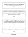
- FIG. 3 shows a flow chart that includes steps of a method of establishing an IPsec (Internet Protocol Security) VPN (Virtual Private Network) tunnel.
- a first step 310 includes receiving, by a wireless mesh network access point, a user configuration, wherein the user configuration includes a type of traffic.
- a second step 320 includes determining an internal interface of the access node based on the type of traffic from at least one physical interface or at least one logical interface, wherein if the type of traffic includes IP traffic, then one of the at least one physical interface is selected, and if the type of traffic includes non-IP traffic, then one of the at least one logical interface is selected.
- a third step 330 includes dynamically determining a local endpoint address for the IPsec VPN tunnel based on whether the selected internal interface is the one of the at least one physical interfaces, the one of the at least one logical interfaces, and whether another IPSec VPN tunnel is already utilizing the selected internal interface.
- a fourth step 340 includes establishing the IPsec VPN tunnel through the selected internal interface of the wireless mesh network access node using the selected local endpoint address.
- the access node further comprises an internal map that maps the selected internal interface with the type of traffic.
- the at least one logical interface is not tied to a physical port, and created to send and receive IP traffic.
- An embodiment further includes encapsulating non-IP packets of non-IP traffic within IP packets.
- determining at least one logical interface for non-IP traffic includes creating the at least one logical interface with an IP address for encapsulating non-IP packets into IP packets and communicating the IP address to a remote VPN device.
- An embodiment further includes de-advertising a route for the IP address in the wireless mesh network if the IP address was previously advertised, thereby preventing the IP address from being accessed directly without going through the IPsec VPN tunnel.
- dynamically determining a local endpoint address for the IPsec VPN tunnel includes determining the local endpoint address to be an address of the selected physical interface if the selected internal interface includes the one of the at least one physical interface physical interface, and a prior IPsec VPN tunnel is not using the selected physical interface.
- dynamically determining a local endpoint address for the IPsec VPN tunnel includes creating a new logical interface, and determining the local endpoint address to be an address of the new logical interface if the selected internal interface includes the one of the at least one physical interface, and a prior IPsec VPN tunnel is using the selected physical interface.
- dynamically determining a local endpoint address for the IPsec VPN tunnel includes determining the local endpoint address to be an address of the selected physical interface if the selected internal interface includes the one of the at least one physical interface on a same VLAN (Virtual Local Area Network) as specified by the user configuration.
- VLAN Virtual Local Area Network
- dynamically determining a local endpoint address for the IPsec VPN tunnel includes creating a new logical interface and determining the local endpoint address to be an address of the new logical interface if the selected internal interface includes the one of the at least one physical interface and an available physical interface is not on a same VLAN (Virtual Local Area Network) as specified by the user configuration.
- VLAN Virtual Local Area Network
- dynamically determining a local endpoint address for the IPsec VPN tunnel includes determining the local endpoint address to be an address of an available physical interface if the selected internal interface includes the one of the at least one logical interface that was selected for non-IP traffic.
- dynamically determining a local endpoint address for the IPsec VPN tunnel includes determining the local endpoint address to be an address of an available physical interface if the selected internal interface includes the one of the at least one logical interface that was selected for non-IP traffic., and the selected physical interface is on a same VLAN (Virtual Local Area Network) as specified by the user configuration.
- VLAN Virtual Local Area Network
- dynamically determining a local endpoint address for the IPsec VPN tunnel includes creating a new logical interface and determining the local endpoint address to be an address of the new logical interface if the selected internal interface includes the one of the at least one logical interface that was selected for non-IP traffic and no physical interface is available.
- dynamically determining a local endpoint address for the IPsec VPN tunnel includes creating a new logical interface and determining the local endpoint address to be an address of the new logical interface if the selected internal interface includes the one of the at least one logical interface that was selected for non-IP traffic and an available physical interface is not on a same VLAN (Virtual Local Area Network) as specified by the user configuration.
- VLAN Virtual Local Area Network
- An embodiment further includes communicating the selected internal interface to a remote device if the selected internal interface includes a logical interface, and statically configuring an IP (internet protocol) using the logical interface.
- IP internet protocol
- An embodiment further includes advertising to the wireless mesh network, the selected local endpoint address if the selected local endpoint address was selected based on creation of a new logical interface, thereby allowing establishment of the IPsec VPN tunnel.
- FIG. 4 show a wireless mesh network access node 400 , according to an embodiment.
- the wireless mesh network access node 400 includes one or more transceivers 420 for communicating with an upstream access node or a first upstream gateway of a wireless mesh network, and a client device.
- the transceivers can be wired or wireless.
- the wireless mesh network access node 400 further includes a controller 400 .
- the controller is operative to receive a user configuration, wherein the user configuration includes a type of traffic, select an internal interface of the access node based on the type of traffic from at least one physical interface or at least one logical interface, wherein if the type of traffic includes IP traffic, then one of the at least one physical interface is selected, and if the type of traffic includes non-IP traffic, then one of the at least one logical interface is selected, dynamically select a local endpoint address for the IPsec VPN tunnel based on whether the selected internal interface is the one of the at least one physical interfaces, the one of the at least one logical interfaces, and whether another IPSec VPN tunnel is already utilizing the selected internal interface, and establish the IPsec VPN tunnel through the selected internal interface of the wireless mesh network access node using the selected local endpoint address.
- the user configuration includes a type of traffic
- the access node further comprises an internal map that maps the selected internal interface with the type of traffic.
- the at least one logical interface is not tied to a physical port, and created to send and receive IP traffic.
- An embodiment further includes encapsulating non-IP packets of non-IP traffic within IP packets.
- determining at least one logical interface for non-IP traffic includes creating the at least one logical interface with an IP address for encapsulating non-IP packets into IP packets and communicating the IP address to a remote VPN device.
- An embodiment further includes de-advertising a route for the IP address in the wireless mesh network if the IP address was previously advertised, thereby preventing the IP address from being accessed directly without going through the IPsec VPN tunnel.
- the access node dynamically determining a local endpoint address for the IPsec VPN tunnel includes determining the local endpoint address to be an address of the selected physical interface if the selected internal interface includes the one of the at least one physical interface physical interface, and a prior IPsec VPN tunnel is not using the selected physical interface.
- the access node dynamically determining a local endpoint address for the IPsec VPN tunnel includes creating a new logical interface, and determining the local endpoint address to be an address of the new logical interface if the selected internal interface includes the one of the at least one physical interface, and a prior IPsec VPN tunnel is using the selected physical interface.
- the access node dynamically determining a local endpoint address for the IPsec VPN tunnel includes determining the local endpoint address to be an address of the selected physical interface if the selected internal interface includes the one of the at least one physical interface on a same VLAN (Virtual Local Area Network) as specified by the user configuration.
- VLAN Virtual Local Area Network
- the access node dynamically determining a local endpoint address for the IPsec VPN tunnel includes creating a new logical interface and determining the local endpoint address to be an address of the new logical interface if the selected internal interface includes the one of the at least one physical interface and an available physical interface is not on a same VLAN (Virtual Local Area Network) as specified by the user configuration.
- VLAN Virtual Local Area Network
- the access node dynamically determining a local endpoint address for the IPsec VPN tunnel includes determining the local endpoint address to be an address of an available physical interface if the selected internal interface includes the one of the at least one logical interface that was selected for non-IP traffic.
- the access node dynamically determining a local endpoint address for the IPsec VPN tunnel includes determining the local endpoint address to be an address of an available physical interface if the selected internal interface includes the one of the at least one logical interface that was selected for non-IP traffic., and the selected physical interface is on a same VLAN (Virtual Local Area Network) as specified by the user configuration.
- VLAN Virtual Local Area Network
- the access node dynamically determining a local endpoint address for the IPsec VPN tunnel includes creating a new logical interface and determining the local endpoint address to be an address of the new logical interface if the selected internal interface includes the one of the at least one logical interface that was selected for non-IP traffic and no physical interface is available.
- the access node dynamically determining a local endpoint address for the IPsec VPN tunnel includes creating a new logical interface and determining the local endpoint address to be an address of the new logical interface if the selected internal interface includes the one of the at least one logical interface that was selected for non-IP traffic and an available physical interface is not on a same VLAN (Virtual Local Area Network) as specified by the user configuration.
- VLAN Virtual Local Area Network
- an embodiment further includes the access node communicating the selected internal interface to a remote device if the selected internal interface includes a logical interface, and statically configuring an IP (internet protocol) using the logical interface.
- IP internet protocol
- an embodiment further includes the access node advertising to the wireless mesh network, the selected local endpoint address if the selected local endpoint address was selected based on creation of a new logical interface, thereby allowing establishment of the IPsec VPN tunnel.
- At least some embodiments include establishment of the IPsec VPN tunnel.
- An embodiment includes IPsec Auto Tunnel Establishment Using Ping Packets.
- Existing methods for setting up an IP VPN tunnel between a client device and a remote network require activity by the client device in order for the tunnel to be established. If there is no activity by the client, no tunnel is established. However, at least some of the embodiments described here do not require the client device to be active.
- the described embodiments include the establishment of an IP VPN tunnel based on a router receiving a client configuration.
- An embodiment includes a method of establishing an IPsec (Internet Protocol Security) VPN (Virtual Private Network) tunnel.
- the method includes receiving, by a router (such as the previously describe wireless access node), a client configuration (the client can be active or not.
- the method further includes selecting, by the router, an IP address, wherein the selected IP address is within a range provided by the client configuration, assigning, by the router, the selected IP address to a temporary logical interface.
- the method further includes, sending, by the router, a ping packet from the temporary logical interface to a remote network (as defined by the client configuration) to open an IPsec VPN tunnel between the router and the remote network, and removing, by the router, the temporary logical interface once the IPsec VPN tunnel is open.
- At least some embodiments further include re-sending, by the router, another ping packet from the temporary logical interface to the remote network if an error is received from the remote network.
- An embodiment includes a router (such as the previously described wireless access node) wherein the router includes one or more processors operative to receive a client configuration; (the client can be active or not), select an IP address, wherein the selected IP address is within a range provided by the client configuration, assign the selected IP address to a virtual interface, send a ping packet from the virtual interface to a remote network (as defined by the client configuration) to open an IPsec (Internet Protocol Security) VPN (Virtual Private Network) tunnel between the router and the remote network, and remove the virtual interface once the IPsec VPN tunnel is open.
- An embodiment of the router further includes the one or more processors operative to re-send another ping packet from the virtual interface to the remote network if an error is received from the remote network.
Abstract
Description
Claims (21)
Priority Applications (2)
| Application Number | Priority Date | Filing Date | Title |
|---|---|---|---|
| US13/868,310 US8893262B2 (en) | 2012-08-30 | 2013-04-23 | Establishing an IPsec (internet protocol security) VPN (virtual private network) tunnel |
| US14/514,536 US9088546B2 (en) | 2012-08-30 | 2014-10-15 | Establishing an IPSEC (internet protocol security) VPN (virtual private network) tunnel and encapsulating non-IP packets |
Applications Claiming Priority (2)
| Application Number | Priority Date | Filing Date | Title |
|---|---|---|---|
| US201261694846P | 2012-08-30 | 2012-08-30 | |
| US13/868,310 US8893262B2 (en) | 2012-08-30 | 2013-04-23 | Establishing an IPsec (internet protocol security) VPN (virtual private network) tunnel |
Related Child Applications (1)
| Application Number | Title | Priority Date | Filing Date |
|---|---|---|---|
| US14/514,536 Continuation US9088546B2 (en) | 2012-08-30 | 2014-10-15 | Establishing an IPSEC (internet protocol security) VPN (virtual private network) tunnel and encapsulating non-IP packets |
Publications (2)
| Publication Number | Publication Date |
|---|---|
| US20140068750A1 US20140068750A1 (en) | 2014-03-06 |
| US8893262B2 true US8893262B2 (en) | 2014-11-18 |
Family
ID=50189417
Family Applications (2)
| Application Number | Title | Priority Date | Filing Date |
|---|---|---|---|
| US13/868,310 Active 2033-07-19 US8893262B2 (en) | 2012-08-30 | 2013-04-23 | Establishing an IPsec (internet protocol security) VPN (virtual private network) tunnel |
| US14/514,536 Active US9088546B2 (en) | 2012-08-30 | 2014-10-15 | Establishing an IPSEC (internet protocol security) VPN (virtual private network) tunnel and encapsulating non-IP packets |
Family Applications After (1)
| Application Number | Title | Priority Date | Filing Date |
|---|---|---|---|
| US14/514,536 Active US9088546B2 (en) | 2012-08-30 | 2014-10-15 | Establishing an IPSEC (internet protocol security) VPN (virtual private network) tunnel and encapsulating non-IP packets |
Country Status (1)
| Country | Link |
|---|---|
| US (2) | US8893262B2 (en) |
Cited By (3)
| Publication number | Priority date | Publication date | Assignee | Title |
|---|---|---|---|---|
| US20150033325A1 (en) * | 2012-08-30 | 2015-01-29 | Tropos Networks, Inc. | Establishing an ipsec (internet protocol security) vpn (virtual private network) tunnel and encapsulating non-ip packets |
| CN105812218A (en) * | 2014-12-31 | 2016-07-27 | 中国电信股份有限公司 | Method for realizing multi-VPN-protocol application access, middleware and mobile terminal |
| US10291524B2 (en) | 2017-08-17 | 2019-05-14 | Abb Schweiz Ag | Dynamic tunnel establishment in a mesh network |
Families Citing this family (29)
| Publication number | Priority date | Publication date | Assignee | Title |
|---|---|---|---|---|
| US9345065B2 (en) * | 2008-11-17 | 2016-05-17 | Qualcomm Incorporated | Remote access to local network |
| US10200325B2 (en) * | 2010-04-30 | 2019-02-05 | Shazzle Llc | System and method of delivering confidential electronic files |
| US9596271B2 (en) * | 2012-10-10 | 2017-03-14 | International Business Machines Corporation | Dynamic virtual private network |
| US9674149B2 (en) * | 2013-03-13 | 2017-06-06 | Facebook, Inc. | System and method for establishing a virtual private network of a mobile device through a preferred network |
| US9455959B1 (en) * | 2013-05-31 | 2016-09-27 | Parallel Wireless, Inc. | Method of connecting security gateway to mesh network |
| US9609492B2 (en) * | 2013-10-17 | 2017-03-28 | Openet Telecom Ltd. | Method and system for dynamically creating tunnels suitable for metering and managing usage data for applications and services |
| US10951522B2 (en) | 2013-11-05 | 2021-03-16 | Cisco Technology, Inc. | IP-based forwarding of bridged and routed IP packets and unicast ARP |
| US9674086B2 (en) | 2013-11-05 | 2017-06-06 | Cisco Technology, Inc. | Work conserving schedular based on ranking |
| US9655232B2 (en) | 2013-11-05 | 2017-05-16 | Cisco Technology, Inc. | Spanning tree protocol (STP) optimization techniques |
| US9769078B2 (en) | 2013-11-05 | 2017-09-19 | Cisco Technology, Inc. | Dynamic flowlet prioritization |
| US9825857B2 (en) | 2013-11-05 | 2017-11-21 | Cisco Technology, Inc. | Method for increasing Layer-3 longest prefix match scale |
| US9397946B1 (en) | 2013-11-05 | 2016-07-19 | Cisco Technology, Inc. | Forwarding to clusters of service nodes |
| US9686180B2 (en) | 2013-11-05 | 2017-06-20 | Cisco Technology, Inc. | Managing routing information for tunnel endpoints in overlay networks |
| US10778584B2 (en) | 2013-11-05 | 2020-09-15 | Cisco Technology, Inc. | System and method for multi-path load balancing in network fabrics |
| US9374294B1 (en) | 2013-11-05 | 2016-06-21 | Cisco Technology, Inc. | On-demand learning in overlay networks |
| US9502111B2 (en) | 2013-11-05 | 2016-11-22 | Cisco Technology, Inc. | Weighted equal cost multipath routing |
| US9509092B2 (en) | 2013-11-06 | 2016-11-29 | Cisco Technology, Inc. | System and apparatus for network device heat management |
| JP2016012909A (en) * | 2014-06-03 | 2016-01-21 | 株式会社リコー | Communication device, communication method and communication system |
| US10116493B2 (en) | 2014-11-21 | 2018-10-30 | Cisco Technology, Inc. | Recovering from virtual port channel peer failure |
| US10142163B2 (en) | 2016-03-07 | 2018-11-27 | Cisco Technology, Inc | BFD over VxLAN on vPC uplinks |
| US10333828B2 (en) | 2016-05-31 | 2019-06-25 | Cisco Technology, Inc. | Bidirectional multicasting over virtual port channel |
| CN111224857A (en) | 2016-06-29 | 2020-06-02 | 华为技术有限公司 | Method and apparatus for implementing a combined virtual private network VPN |
| CN106209838B (en) * | 2016-07-08 | 2020-01-03 | 杭州迪普科技股份有限公司 | IP access method and device of SSL VPN |
| US11509501B2 (en) | 2016-07-20 | 2022-11-22 | Cisco Technology, Inc. | Automatic port verification and policy application for rogue devices |
| US10193750B2 (en) | 2016-09-07 | 2019-01-29 | Cisco Technology, Inc. | Managing virtual port channel switch peers from software-defined network controller |
| US10362612B2 (en) * | 2017-03-06 | 2019-07-23 | Citrix Systems, Inc. | Virtual private networking based on peer-to-peer communication |
| US10547509B2 (en) | 2017-06-19 | 2020-01-28 | Cisco Technology, Inc. | Validation of a virtual port channel (VPC) endpoint in the network fabric |
| US10673813B2 (en) * | 2018-02-01 | 2020-06-02 | National Chiao Tung University | Method for NAT traversal in VPN |
| US11323287B2 (en) * | 2019-07-18 | 2022-05-03 | International Business Machines Corporation | Link layer method of configuring a bare-metal server in a virtual network |
Citations (18)
| Publication number | Priority date | Publication date | Assignee | Title |
|---|---|---|---|---|
| US6704301B2 (en) | 2000-12-29 | 2004-03-09 | Tropos Networks, Inc. | Method and apparatus to provide a routing protocol for wireless devices |
| US6965575B2 (en) | 2000-12-29 | 2005-11-15 | Tropos Networks | Selection of routing paths based upon path quality of a wireless mesh network |
| US7031293B1 (en) | 2001-03-26 | 2006-04-18 | Tropos Networks, Inc. | Method and system to provide increased data throughput in a wireless multi-hop network |
| US7131141B1 (en) * | 2001-07-27 | 2006-10-31 | At&T Corp. | Method and apparatus for securely connecting a plurality of trust-group networks, a protected resource network and an untrusted network |
| US20080013474A1 (en) | 2006-07-14 | 2008-01-17 | Symbol Technologies, Inc. | Wireless switch network architecture implementing layer 3 mobility domains |
| US20080020759A1 (en) | 2006-07-20 | 2008-01-24 | Symbol Technologies, Inc. | Techniques for home wireless switch redundancy and stateful switchover in a network of wireless switches supporting layer 3 mobility within a mobility domain |
| US7376087B2 (en) | 2003-08-13 | 2008-05-20 | Tropos Networks, Inc. | Method and apparatus for monitoring and displaying routing metrics of a network |
| US20080183853A1 (en) | 2007-01-30 | 2008-07-31 | Microsoft Corporation | Private virtual lan spanning a public network for connection of arbitrary hosts |
| US7447901B1 (en) * | 2002-06-25 | 2008-11-04 | Cisco Technology, Inc. | Method and apparatus for establishing a dynamic multipoint encrypted virtual private network |
| US20090034470A1 (en) | 2007-07-31 | 2009-02-05 | Symbol Technologies, Inc. | Forwarding broadcast/multicast data when wireless clients layer 3 roam across ip subnets in a wlan |
| US7505426B2 (en) | 2000-12-29 | 2009-03-17 | Tropos Networks | Multi-channel mesh network |
| US20090097490A1 (en) | 2003-05-08 | 2009-04-16 | Onvoy, Inc. | Communications network with converged services |
| US7551562B2 (en) | 2000-12-29 | 2009-06-23 | Tropos Networks | Determining bidirectional path quality within a wireless mesh network |
| US7688808B2 (en) | 2006-03-21 | 2010-03-30 | Tropos Networks, Inc. | Mobile access node routing selections through a mesh network |
| US20110004913A1 (en) | 2007-07-31 | 2011-01-06 | Symbol Technologies, Inc. | Architecture for seamless enforcement of security policies when roaming across ip subnets in ieee 802.11 wireless networks |
| US7917948B2 (en) * | 2002-06-25 | 2011-03-29 | Cisco Technology, Inc. | Method and apparatus for dynamically securing voice and other delay-sensitive network traffic |
| US20120096269A1 (en) * | 2010-10-14 | 2012-04-19 | Certes Networks, Inc. | Dynamically scalable virtual gateway appliance |
| US20120188934A1 (en) | 2009-10-06 | 2012-07-26 | Hang Liu | Method and apparatus for hop-by-hop reliable multicast in wireless networks |
Family Cites Families (1)
| Publication number | Priority date | Publication date | Assignee | Title |
|---|---|---|---|---|
| US8893262B2 (en) * | 2012-08-30 | 2014-11-18 | Tropos Networks, Inc. | Establishing an IPsec (internet protocol security) VPN (virtual private network) tunnel |
-
2013
- 2013-04-23 US US13/868,310 patent/US8893262B2/en active Active
-
2014
- 2014-10-15 US US14/514,536 patent/US9088546B2/en active Active
Patent Citations (22)
| Publication number | Priority date | Publication date | Assignee | Title |
|---|---|---|---|---|
| US6704301B2 (en) | 2000-12-29 | 2004-03-09 | Tropos Networks, Inc. | Method and apparatus to provide a routing protocol for wireless devices |
| US6965575B2 (en) | 2000-12-29 | 2005-11-15 | Tropos Networks | Selection of routing paths based upon path quality of a wireless mesh network |
| US7058021B2 (en) | 2000-12-29 | 2006-06-06 | Tropos Networks, Inc. | Selection of routing paths based upon routing packet success ratios of wireless routes within a wireless mesh network |
| US7689224B2 (en) | 2000-12-29 | 2010-03-30 | Tropos Networks, Inc. | Method and apparatus to provide a routing protocol for wireless devices |
| US7551562B2 (en) | 2000-12-29 | 2009-06-23 | Tropos Networks | Determining bidirectional path quality within a wireless mesh network |
| US7397789B2 (en) | 2000-12-29 | 2008-07-08 | Tropos Networks, Inc. | Providing routing paths for wireless devices |
| US7505426B2 (en) | 2000-12-29 | 2009-03-17 | Tropos Networks | Multi-channel mesh network |
| US7031293B1 (en) | 2001-03-26 | 2006-04-18 | Tropos Networks, Inc. | Method and system to provide increased data throughput in a wireless multi-hop network |
| US7668137B2 (en) | 2001-03-26 | 2010-02-23 | Tropos Networks, Inc. | Method and system to provide increased data throughput in a wireless multi-hop network |
| US7131141B1 (en) * | 2001-07-27 | 2006-10-31 | At&T Corp. | Method and apparatus for securely connecting a plurality of trust-group networks, a protected resource network and an untrusted network |
| US7447901B1 (en) * | 2002-06-25 | 2008-11-04 | Cisco Technology, Inc. | Method and apparatus for establishing a dynamic multipoint encrypted virtual private network |
| US7917948B2 (en) * | 2002-06-25 | 2011-03-29 | Cisco Technology, Inc. | Method and apparatus for dynamically securing voice and other delay-sensitive network traffic |
| US20090097490A1 (en) | 2003-05-08 | 2009-04-16 | Onvoy, Inc. | Communications network with converged services |
| US7376087B2 (en) | 2003-08-13 | 2008-05-20 | Tropos Networks, Inc. | Method and apparatus for monitoring and displaying routing metrics of a network |
| US7688808B2 (en) | 2006-03-21 | 2010-03-30 | Tropos Networks, Inc. | Mobile access node routing selections through a mesh network |
| US20080013474A1 (en) | 2006-07-14 | 2008-01-17 | Symbol Technologies, Inc. | Wireless switch network architecture implementing layer 3 mobility domains |
| US20080020759A1 (en) | 2006-07-20 | 2008-01-24 | Symbol Technologies, Inc. | Techniques for home wireless switch redundancy and stateful switchover in a network of wireless switches supporting layer 3 mobility within a mobility domain |
| US20080183853A1 (en) | 2007-01-30 | 2008-07-31 | Microsoft Corporation | Private virtual lan spanning a public network for connection of arbitrary hosts |
| US20090034470A1 (en) | 2007-07-31 | 2009-02-05 | Symbol Technologies, Inc. | Forwarding broadcast/multicast data when wireless clients layer 3 roam across ip subnets in a wlan |
| US20110004913A1 (en) | 2007-07-31 | 2011-01-06 | Symbol Technologies, Inc. | Architecture for seamless enforcement of security policies when roaming across ip subnets in ieee 802.11 wireless networks |
| US20120188934A1 (en) | 2009-10-06 | 2012-07-26 | Hang Liu | Method and apparatus for hop-by-hop reliable multicast in wireless networks |
| US20120096269A1 (en) * | 2010-10-14 | 2012-04-19 | Certes Networks, Inc. | Dynamically scalable virtual gateway appliance |
Cited By (4)
| Publication number | Priority date | Publication date | Assignee | Title |
|---|---|---|---|---|
| US20150033325A1 (en) * | 2012-08-30 | 2015-01-29 | Tropos Networks, Inc. | Establishing an ipsec (internet protocol security) vpn (virtual private network) tunnel and encapsulating non-ip packets |
| US9088546B2 (en) * | 2012-08-30 | 2015-07-21 | Abb Inc. | Establishing an IPSEC (internet protocol security) VPN (virtual private network) tunnel and encapsulating non-IP packets |
| CN105812218A (en) * | 2014-12-31 | 2016-07-27 | 中国电信股份有限公司 | Method for realizing multi-VPN-protocol application access, middleware and mobile terminal |
| US10291524B2 (en) | 2017-08-17 | 2019-05-14 | Abb Schweiz Ag | Dynamic tunnel establishment in a mesh network |
Also Published As
| Publication number | Publication date |
|---|---|
| US20150033325A1 (en) | 2015-01-29 |
| US20140068750A1 (en) | 2014-03-06 |
| US9088546B2 (en) | 2015-07-21 |
Similar Documents
| Publication | Publication Date | Title |
|---|---|---|
| US9088546B2 (en) | Establishing an IPSEC (internet protocol security) VPN (virtual private network) tunnel and encapsulating non-IP packets | |
| USRE49485E1 (en) | Overlay management protocol for secure routing based on an overlay network | |
| JP4675909B2 (en) | Multihoming and service network selection using IP access network | |
| US7373660B1 (en) | Methods and apparatus to distribute policy information | |
| EP2579544B1 (en) | Methods and apparatus for a scalable network with efficient link utilization | |
| US8763109B2 (en) | Seamless data networking | |
| CN105471596B (en) | The method and apparatus of network management | |
| US9762484B2 (en) | Role based router functionality | |
| CN112584393B (en) | Base station configuration method, device, equipment and medium | |
| CN103188351B (en) | IPSec VPN traffic method for processing business and system under IPv6 environment | |
| US10298616B2 (en) | Apparatus and method of securing network communications | |
| CN110290093A (en) | The SD-WAN network architecture and network-building method, message forwarding method | |
| WO2014194749A1 (en) | Vpn implementation processing method and apparatus for edge device | |
| JP2004357292A (en) | System for converting data transferred on ip switched network from ipv4 base into ipv6 base | |
| KR20150020530A (en) | Multi-tunnel virtual private network | |
| CN104023022B (en) | A kind of IPSec SA acquisition methods and device | |
| JP2021510045A (en) | Systems and methods for creating group networks between network devices | |
| Carlson et al. | PPP transparent interconnection of lots of links (TRILL) protocol control protocol | |
| JP2016533076A (en) | Network probe routing | |
| WO2020215657A1 (en) | Two-dimensional routing protocol-based l3vpn implementation method and system | |
| Carthern et al. | Advanced Routing | |
| Cisco | IP Routing and Bridging | |
| US20130133063A1 (en) | Tunneling-based method of bypassing internet access denial | |
| KR101712922B1 (en) | Virtual Private Network System of Dynamic Tunnel End Type, Manager Apparatus and Virtual Router for the same | |
| CN117424778B (en) | Method for realizing large two-layer communication across control domain SD-WAN network |
Legal Events
| Date | Code | Title | Description |
|---|---|---|---|
| AS | Assignment |
Owner name: TROPOS NETWORKS, INC., CALIFORNIA Free format text: ASSIGNMENT OF ASSIGNORS INTEREST;ASSIGNORS:TJAHJONO, DANU;SHAIKH, RAFIQ;REN, WENGE;REEL/FRAME:030264/0752 Effective date: 20130419 |
|
| STCF | Information on status: patent grant |
Free format text: PATENTED CASE |
|
| FEPP | Fee payment procedure |
Free format text: PAYOR NUMBER ASSIGNED (ORIGINAL EVENT CODE: ASPN); ENTITY STATUS OF PATENT OWNER: LARGE ENTITY |
|
| MAFP | Maintenance fee payment |
Free format text: PAYMENT OF MAINTENANCE FEE, 4TH YEAR, LARGE ENTITY (ORIGINAL EVENT CODE: M1551) Year of fee payment: 4 |
|
| AS | Assignment |
Owner name: ABB INC., NORTH CAROLINA Free format text: MERGER;ASSIGNOR:TROPOS NETWORKS, INC.;REEL/FRAME:054380/0829 Effective date: 20141219 |
|
| AS | Assignment |
Owner name: ABB POWER GRIDS SWITZERLAND AG, SWITZERLAND Free format text: ASSIGNMENT OF ASSIGNORS INTEREST;ASSIGNOR:ABB INC.;REEL/FRAME:055594/0148 Effective date: 20201202 |
|
| AS | Assignment |
Owner name: HITACHI ENERGY SWITZERLAND AG, SWITZERLAND Free format text: CHANGE OF NAME;ASSIGNOR:ABB POWER GRIDS SWITZERLAND AG;REEL/FRAME:058666/0540 Effective date: 20211006 |
|
| MAFP | Maintenance fee payment |
Free format text: PAYMENT OF MAINTENANCE FEE, 8TH YEAR, LARGE ENTITY (ORIGINAL EVENT CODE: M1552); ENTITY STATUS OF PATENT OWNER: LARGE ENTITY Year of fee payment: 8 |
|
| AS | Assignment |
Owner name: HITACHI ENERGY LTD, SWITZERLAND Free format text: MERGER;ASSIGNOR:HITACHI ENERGY SWITZERLAND AG;REEL/FRAME:065549/0576 Effective date: 20231002 |