US8894592B2 - Device and method for decreasing oxygen consumption of a person during steady walking by use of a load-carrying exoskeleton - Google Patents
Device and method for decreasing oxygen consumption of a person during steady walking by use of a load-carrying exoskeleton Download PDFInfo
- Publication number
- US8894592B2 US8894592B2 US12/468,487 US46848709A US8894592B2 US 8894592 B2 US8894592 B2 US 8894592B2 US 46848709 A US46848709 A US 46848709A US 8894592 B2 US8894592 B2 US 8894592B2
- Authority
- US
- United States
- Prior art keywords
- torque
- swing
- leg support
- exoskeleton
- hip
- Prior art date
- Legal status (The legal status is an assumption and is not a legal conclusion. Google has not performed a legal analysis and makes no representation as to the accuracy of the status listed.)
- Active, expires
Links
Images


Classifications
-
- B—PERFORMING OPERATIONS; TRANSPORTING
- B25—HAND TOOLS; PORTABLE POWER-DRIVEN TOOLS; MANIPULATORS
- B25J—MANIPULATORS; CHAMBERS PROVIDED WITH MANIPULATION DEVICES
- B25J9/00—Programme-controlled manipulators
- B25J9/0006—Exoskeletons, i.e. resembling a human figure
-
- A—HUMAN NECESSITIES
- A61—MEDICAL OR VETERINARY SCIENCE; HYGIENE
- A61F—FILTERS IMPLANTABLE INTO BLOOD VESSELS; PROSTHESES; DEVICES PROVIDING PATENCY TO, OR PREVENTING COLLAPSING OF, TUBULAR STRUCTURES OF THE BODY, e.g. STENTS; ORTHOPAEDIC, NURSING OR CONTRACEPTIVE DEVICES; FOMENTATION; TREATMENT OR PROTECTION OF EYES OR EARS; BANDAGES, DRESSINGS OR ABSORBENT PADS; FIRST-AID KITS
- A61F5/00—Orthopaedic methods or devices for non-surgical treatment of bones or joints; Nursing devices; Anti-rape devices
- A61F5/01—Orthopaedic devices, e.g. splints, casts or braces
- A61F5/0102—Orthopaedic devices, e.g. splints, casts or braces specially adapted for correcting deformities of the limbs or for supporting them; Ortheses, e.g. with articulations
-
- A—HUMAN NECESSITIES
- A61—MEDICAL OR VETERINARY SCIENCE; HYGIENE
- A61H—PHYSICAL THERAPY APPARATUS, e.g. DEVICES FOR LOCATING OR STIMULATING REFLEX POINTS IN THE BODY; ARTIFICIAL RESPIRATION; MASSAGE; BATHING DEVICES FOR SPECIAL THERAPEUTIC OR HYGIENIC PURPOSES OR SPECIFIC PARTS OF THE BODY
- A61H3/00—Appliances for aiding patients or disabled persons to walk about
- A61H3/008—Using suspension devices for supporting the body in an upright walking or standing position, e.g. harnesses
Definitions
- the lower extremity exoskeleton described here is configurable to be coupled to a person and, among other components, comprises: two leg supports configurable to be coupled to the person's lower limbs; two knee joints, each of which is configured to allow flexion and extension between a respective shank link and a respective thigh link; an exoskeleton trunk, which is configurable to be coupled to the person's upper body and is rotatably connectable to the thigh links of the leg supports, allowing for the flexion and extension between the leg supports and the exoskeleton trunk; two hip actuators, which are configured to create torques between the exoskeleton trunk and leg supports; and at least one power unit, which is capable of providing power to the hip actuators, among other components.
- the hip actuator of the second leg support When the second leg support enters the stance phase, the hip actuator of the second leg support rapidly creates the first, unidirectional torque and the hip actuator of the first leg support rapidly creates a second unidirectional torque acting in a direction to move the first leg support forward relative to the exoskeleton trunk until the first leg support leaves the ground and enters the swing phase.
- the exoskeleton device reduces the energy consumed by a person while walking as compared to a person without the exoskeleton device, thereby decreasing the person's oxygen consumption and heart rate.
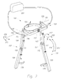
- FIG. 1 is a front perspective drawing of an exoskeleton of the present invention including hip actuators;
- FIG. 2 is a rear perspective drawing of the exoskeleton of FIG. 1 ;
- FIG. 3 is a diagram of torque profiles for the hip actuators of FIG. 1 during a walking cycle
- FIG. 4 is a chart of the total torque of the hip actuators of FIG. 1 over time during a walking cycle
- FIG. 5 is a chart of human hip torque (joint movement relative to percent cycle time) during a hip extension movement
- FIG. 6 is a schematic drawing of a power unit of the present invention.
- FIG. 7 is a schematic drawing of an alternative power unit of the present invention including a flow restrictive valve
- FIG. 9 is a perspective drawing of an alternative exoskeleton of the present invention including stance sensors in communication with a signal processor;
- FIG. 10 is a perspective drawing of an alternative exoskeleton of the present invention including a hip resilient element
- FIG. 11 is a perspective drawing of an alternative exoskeleton of the present invention including a connecting bracket for carrying a rear load;
- FIG. 13 is a perspective drawing of an alternative exoskeleton of the present invention including a hip abduction stop
- FIG. 16 is a perspective drawing of an alternative exoskeleton of the present invention including two hip joints;
- FIG. 17 is a perspective drawing of an alternative exoskeleton of the present invention including a back pack frame;
- FIG. 18 is a perspective drawing of an alternative exoskeleton of the present invention including two hip resilient elements and exoskeleton feet;
- FIG. 19 is a partial view of the exoskeleton of FIG. 18 , showing thigh joint details
- FIG. 20 is a partial view of the exoskeleton of FIG. 18 showing details of a compression-elongation mechanism
- FIG. 21 is a perspective drawing of an alternative exoskeleton of the present invention including shoes
- FIG. 22 is a perspective drawing of an alternative exoskeleton of the present invention including insoles;
- FIG. 23 is partial view of an exoskeleton foot of FIG. 18 including a ball and socket joint;
- FIG. 24 is a perspective drawing of an alternative exoskeleton foot of the present invention including resilient elements
- FIG. 25 is a perspective drawing of an alternative exoskeleton foot of the present invention including an abduction-adduction resilient element
- FIG. 26 is a perspective drawing of an alternative exoskeleton foot of the present invention including a shank rotating joint
- FIG. 27 is a chart showing oxygen consumption of subjects coupled to exoskeletons of the present invention compared to oxygen consumption of subjects with no exoskeleton:
- FIG. 28 is a partial cross-sectional side view of an alternative exoskeleton foot of the present invention including an integrated stance sensor;
- FIG. 29 is a top perspective view of an alternative exoskeleton foot of the present invention including a force sensor
- FIG. 30 is a partial cross-sectional side view of an alternative shoe of the present invention including an integrated stance sensor
- FIG. 31 is a partial cross-sectional side view of an alternative shoe of the present invention including a sole-mounted stance sensor
- FIG. 32 is a partial cross-sectional side view of an alternative shoe of the present invention including a force sensor incorporated into the shoe sole;
- FIG. 33 is a side view of an alternative exoskeleton of the present invention carried in a vertical stowed position
- FIG. 34 is a partial perspective view of the exoskeleton of FIG. 33 ;
- FIG. 35 is a perspective drawing of an alternative exoskeleton foot of the present invention including hydraulic rotary dampers;
- FIG. 36 depicts the function of a locking knee joint in accordance with the present invention.
- FIG. 38 is a side view of an alternative right leg support of the present invention including knee resilient elements in series with torque generators.
- the present invention provides for an exoskeleton device that actually decreases a wearer's oxygen consumption.
- a lower extremity exoskeleton 100 wearable by a person 187 is able to decrease the wearer's oxygen consumption.
- Lower extremity exoskeleton 100 in addition to other components, includes two leg supports 101 and 102 , which are configured to be coupled to person's lower limbs 143 and 144 and configured to rest on the a support surface (e.g., the ground) during their stance phase.
- stance phase should be understood to mean the position a leg support 101 or 102 is in when a downward force is being applied to a user's foot and leg associated with the leg support 101 or 102 and the leg support 101 or 102 is in contact with the ground.
- the leg supports include thigh links 103 and 104 and shank links 105 and 106 .
- Two knee joints 107 and 108 are configured to allow flexion and extension between the shank link and the thigh link of the leg supports (shown by knee flexion arrow 213 and knee extension arrow 214 , respectively) during the corresponding leg support swing phase and later part of the stance phase.
- Person's upper body 149 means any location generally above the thighs, including the buttock.
- Examples of upper body interface device 150 include an element or combination of elements including, without limitation, vests, belts, straps, shoulder straps, chest straps, body cast, harness, and waist belts.
- Exoskeleton trunk 109 is rotatably connectable to leg supports 101 and 102 at hip flexion-extension joints 125 and 126 , allowing for the hip flexion and extension rotations (shown by hip extension arrow 215 and hip flexion arrow 216 , respectively) of leg supports 101 and 102 about hip flexion-extension axes 151 and 152 , respectively.
- Leg supports 101 and 102 are configurable to be coupled to person's lower limbs 143 and 144 through lower limb interface straps 135 and 136 .
- lower limb interface straps 135 and 136 are coupled to thigh links 103 and 104 .
- lower limb interface straps 135 and 136 are coupled to shank links 105 and 106 .
- lower limb interface straps are coupled to both shank links and thigh links.
- Each lower limb interface strap 135 and 136 comprises an element or combination of elements including, without limitation, straps, bars, c-shaped brackets, body cast, and elastomers.
- person 187 couples to (or wears) lower extremity exoskeleton 100 through upper body interface device 150 (a simple belt in the case of FIG.
- Rip actuators 145 and 146 comprise any device or combination of devices capable of providing torque.
- hip actuators 145 and 146 include, without limitation, electric motors, including, without limitation, AC (alternating current) motors, brush-type DC (direct current) motors, brushless DC motors, electronically commutated motors (ECMs), stepping motors, hydraulic actuators, and pneumatic actuators and combinations thereof.
- hip actuators 145 and 146 are powered by compressed gas.
- exoskeleton trunk 109 is configured to hold a rear load behind person 187 .
- Lower extremity exoskeleton 100 reduces its wearer's energy expenditure and oxygen consumption when the correct torques are produced by hip actuators 145 and 146 .
- the operation of lower extremity exoskeleton 100 can best be described by inspection of FIG. 3 .
- FIG. 3 shows the torque being imposed by hip actuators 145 and 146 on exoskeleton trunk 109 during a walking cycle, where T 1 and T 2 represent the instances where right leg support 101 and left leg support 102 strike ground 130 , respectively.
- power unit 201 When left leg support 102 strikes ground 130 , power unit 201 performs two operations: 1) it causes hip actuator 146 of left leg support 102 to create the same first unidirectional torque which acts to move left leg support 102 backwardly relative to exoskeleton trunk 109 (this torque pushes exoskeleton trunk 109 forward when left leg support 102 is on the ground), and 2) it forces hip actuator 145 to create a second unidirectional torque acting in a direction to move right leg support 101 forward relative to exoskeleton trunk 109 . This second unidirectional torque is in effect until right leg support 101 leaves ground 130 (i.e., T 3 ). T 4 represents the time where right leg, support 101 strikes ground 130 again and re-enters its stance phase.
- power unit 201 causes hip actuator 145 of right leg support 101 to create a swing torque acting in a direction to move said right leg support 101 forward relative to exoskeleton trunk 109 .
- this swing torque will reduce the wearer's effort in swinging her/his leg and consequently will reduce the wearer's energy expenditure and oxygen consumption.
- the torque of hip actuator 146 is the same as the torque of hip actuator 145 , but shifted in time.
- the second unidirectional torque is in effect during double stance only (between T 2 and T 3 )
- the total torque from both hip actuators 145 and 146 applied to exoskeleton trunk 109 during the double stance phase will be equal to the algebraic addition of both the first and the second unidirectional torques.
- the magnitude of the second unidirectional torque is generally smaller than the magnitude of the first unidirectional torque. This ensures that, during the double stance phase, the total torque from hip actuators 145 and 146 to exoskeleton trunk 109 is unidirectional, pushing exoskeleton trunk 109 and person 187 forward.
- FIG. 4 shows the total torque being imposed by hip actuators 145 and 146 on exoskeleton trunk 109 over a walking cycle.
- This torque is unidirectional throughout the walking cycle, which results in pushing exoskeleton trunk 109 and person 187 forward and allows stable walking.
- the sum of the torques from hip actuators 145 and 146 onto exoskeleton trunk 109 acts in the direction of hip extension at all times. This results in less energy expenditure by person 187 . Less energy consumption results in less oxygen consumption.
- the sum of the torques from hip actuators 145 and 146 onto exoskeleton trunk 109 is generally constant. In some embodiments of the invention, the sum of the torques from hip actuators 145 and 146 onto exoskeleton trunk 109 drops to no less than 50% of its maximum value at any time, and preferably drops to no less than 30% of its maximum value at any time.
- the maximum value should be understood as the maximum torque from hip actuators 145 and 146 applied to exoskeleton trunk 109 at any time during forward motion of the exoskeleton. This ensures that the user can walk comfortably without large torque variation on exoskeleton trunk 109 and person's upper body 149 .
- the second unidirectional torque is zero. This means that when a leg support strikes the ground, the hip actuator of the opposite leg support that had already been on the ground creates no more torque. For example, if right leg support 101 is in its stance phase and left leg support 102 strikes ground 130 , hip actuator 145 of right leg support 101 will stop imposing torque.
- the first unidirectional torque is generally constant, which can result in greater user comfort.
- the second unidirectional torque is generally constant, which can result in greater user comfort.
- the first unidirectional torque generally decreases in value during the single stance phase (when only one leg support is in the stance phase), which results in greater user comfort.
- FIG. 5 shows experimentally measured human hip torque taken from the literature below, incorporated herein by reference:
- FIG. 5 illustrates that human hip torque is positive during early stance, but becomes negative during the stance phase, changing its direction.
- the present invention preferably provides for a hip torque that is completely unidirectional during the stance phase, which has been determined empirically to produce the desired effect of reducing oxygen consumption.
- swing torque is unidirectional during the swing phase, swinging the leg support forward. To save power, in some embodiments of the invention, swing torque is zero.
- the swing torque is proportional to the angular velocity of swinging leg support (either with respect to exoskeleton trunk 109 or ground 130 ) and acts in a direction which magnifies the angular velocity of the swinging leg support.
- the swing torque may be generated through the summation of any of several terms, including: a torque proportional to the angular velocity of leg support 101 in a direction that increases the angular velocity of leg support 101 ; a torque proportional to the angular acceleration of leg support 101 in a direction that increases the angular acceleration, of leg support 101 (either with respect to exoskeleton trunk 109 or ground 130 ); and a torque proportional to the sine of the hip angle of leg support 101 , which acts in a direction to generally counteract the torque imposed on leg support 101 due to gravity.
- the first unidirectional torque when right leg support 101 is in the single stance phase (e.g., left leg support 102 is in the swing phase) the first unidirectional torque may be a summation which includes a component proportional to the negative of the swing torque being generated by hip actuator 146 of leg support 102 . In some embodiments, this component will be equal to the negative of the swing torque being generated by hip actuator 146 of leg support 102 .
- each of hip actuators 145 and 146 comprises a hydraulic hip actuator.
- at least one power unit 201 provides hydraulic power to hip actuators 145 and 146 .
- only one power unit 201 provides hydraulic power to hydraulic hip actuators 145 and 146 .
- each hydraulic hip actuator receives hydraulic power from separate power units.
- power unit 201 as shown in FIG. 6 , among other components, comprises at least one hydraulic circuit 194 connectable to at least one of hydraulic hip actuators 145 and 146 , and modulates the hydraulic fluid flow to and from hydraulic hip actuators 145 and 146 .
- hydraulic hip actuators 145 and 146 are hydraulic piston-cylinders.
- hydraulic hip actuators 145 and 146 are rotary hydraulic vane type hydraulic actuators.
- hydraulic circuit 194 comprises a hydraulic pump 240 coupled to an electric motor 241 .
- the torque profile of FIG. 3 can be implemented on hip actuators 145 and 146 . Since the torque is a function of the hydraulic pressure and the hip actuator geometry, the hip actuator torque can be controlled by creating a closed loop control on the electric motor 241 by measuring the hydraulic pressure as the feedback variable. In some embodiments, the hip actuator torque can be controlled to follow the trajectory of FIG. 3 by creating a closed loop control on the electric motor 241 by measuring the hip actuator torque or force as the feedback variable.
- hydraulic circuit 194 further comprises an actuated flow restricting valve 200 capable of redirecting hydraulic fluid from hydraulic right hip actuator 145 around hydraulic pump 240 .
- actuated flow restricting valve 200 In operation, when hydraulic pump 240 is in use, actuated flow restricting valve 200 is closed. In operation, when it is necessary to reduce the power consumption, electric motor 241 will not be powered. In that case, actuated flow restricting valve 200 may be opened so that unpowered electric motor 241 and pump 240 will not impede the motion of right hip actuator 145 .
- hydraulic circuit 194 further comprises a three-way valve 242 .
- three-way valve 242 connects hydraulic right hip actuator 145 to hydraulic pump 240 .
- electric motor 241 when it is necessary to reduce the power consumption, electric motor 241 will not be powered.
- three-way valve 242 may redirect hydraulic fluid from hydraulic right hip actuator 145 around hydraulic pump 240 so that unpowered electric motor 241 and pump 240 will not impede the motion of right hip actuator 145 .
- Hydraulic hip actuators 145 and 146 can comprise any hydraulic actuators or combination of actuators capable of converting pressurized hydraulic fluid into force or torque.
- hydraulic actuators include, without limitation, linear hydraulic piston-cylinders, rotary hydraulic actuators, rack-and-pinion-type rotary actuators, and rotary hydraulic vane type actuators where pressurized hydraulic fluid, by pushing against moving surfaces, generate force or torque.
- Actuated flow restricting valve 200 comprises any valve or combination of valves capable of performing the indicated functions. Examples of actuated flow restricting valve 200 include, without limitation, flow control valve, pressure control valve, actuated needle valves, solenoid valves and on-off valve.
- Hydraulic pump 240 comprises any pump or combination of pumps capable of performing the indicated functions.
- Examples of hydraulic pump 240 include, without limitation, a gear pump, vane pump, axial piston pump, and radial piston pump.
- Electric motor 241 comprises any device or combination of devices capable of driving hydraulic pump 240 .
- Examples of motor 241 include, without limitation, electric motors, including, without limitation, AC (alternating current) motors, brush-type DC (direct current) motors, brushless DC motors, electronically commutated motors (ECMs), stepping motors, and combinations thereof.
- AC alternating current
- brush-type DC direct current
- brushless DC brushless DC
- ECMs electronically commutated motors
- stepping motors and combinations thereof.
- lower extremity exoskeleton 100 comprises at least one signal processor 159 capable of controlling hip actuators 145 and 146 .
- Signal processor 159 comprises an element or combination of elements selected from the group consisting of analog devices; analog computation modules; digital devices including, without limitation, small-, medium-, and large-scale integrated circuits, application specific integrated circuits, programmable gate arrays, programmable logic arrays; electromechanical relays, solid state switches, MOSFET switches and digital computation modules including, without limitation, microcomputers, microprocessors, microcontrollers, and programmable logic controllers.
- signal processor 159 computes a torque profile that follows the torque profile shown in FIG. 3 . This torque is then produced by hip actuators 145 and 146 during their respective stance phases.
- hip actuators 145 and 146 are hydraulic actuators
- signal processor 159 by controlling electric motor 241 , computes a torque profile, as shown in FIG. 3 , for hip actuators 145 and 146 . Since the torque is a function of the hydraulic pressure and the hip actuator geometry, the hip actuator torque, in some embodiments, as shown in FIG. 8 , can be controlled by creating a closed loop control on the electric motor 241 by measuring the hydraulic pressure as the feedback variable. Pressure sensor 236 measures the pressure of the hydraulic fluid and signal processor 159 ensures the pressure is regulated to the desired value. In some embodiments, the hip actuator torque can be controlled to follow the architecture of FIG. 3 by creating a closed loop control on the electric motor 241 by measuring the hip actuator torque or force as the feedback variable.
- Signal processor 159 in some embodiments, is mounted to exoskeleton trunk 109 . In other embodiments, signal processor 159 is located inside power unit 201 . Signal processor 159 may be a simple mechanical device constituted by, a hydraulic or pneumatic circuit or it may include electronic elements as well.
- lower extremity exoskeleton 100 comprises at least one stance sensor per leg support, which produces a stance signal indicating whether that leg support is in, the stance phase.
- leg support 101 includes stance sensor 160 , which produces a stance signal 219 .
- Stance signal 219 indicates whether leg support 101 is in the stance phase.
- leg support 102 includes stance sensor 161 , which produces a stance signal 220 .
- Stance signal 220 indicates whether leg support 102 is in the stance phase.
- stance sensors 160 and 161 are coupled to shank links leg support 101 and 102 , respectively.
- signal processor 159 computes a torque profile according to the shape of FIG. 3 depending on whether stance signals 219 and 220 indicate if leg supports 101 and 102 are either in the stance phase or in the swing phase.
- stance sensors 160 and 161 are located inside the human shoe (or boot) soles. In some embodiments, stance sensors 160 and 161 are located inside the human shoes or boots. In some embodiments, stance sensors 160 and 161 are connectable to the bottom of human shoes or boots.
- exoskeleton trunk 109 in addition to other components, comprises two hip links 114 and 115 rotatably connectable to thigh links 103 and 104 at hip flexion-extension joints 125 and 126 , allowing for the flexion and extension of leg supports 101 and 102 about hip flexion-extension axes 151 and 152 , respectively.
- hip links 114 and 115 are rotatably connected to each other at hip abduction-adduction joint 113 , allowing for abduction and/or adduction of leg supports 101 and 102 .
- Abduction and adduction of leg supports 101 and 102 are shown by arrows 217 and 218 , respectively.
- FIG. 10 shows another embodiment of the invention where exoskeleton trunk 109 further comprises a hip resilient element 116 configured to apply a torque between hip links 114 and 115 .
- hip resilient element include, without limitation, extension spring, compression spring, leaf spring, gas spring, air spring, rubber, elastomer, surgical tube, bungee cord and combinations thereof.
- the stiffness of hip resilient element 116 may be chosen such that its force generally holds up the weight of the leg supports 101 or 102 during a swing phase.
- exoskeleton trunk 109 is configured to hold a rear load 118 behind person 187 .
- FIG. 11 is a perspective drawing wherein exoskeleton trunk 109 , among other components, further comprises a connecting bracket 117 configured to transfer the weight of a rear load 118 to exoskeleton trunk 109 .
- connecting bracket 117 further comprises extension frames 119 and 120 , configured to hold front load 154 in front of person 187 .
- Examples of rear load 118 and front load 154 include, without limitation, backpack, baby carrier, food containers, sacks, boxes, water jugs, tool boxes, barrels, ammunition, weaponry, bedding, first aid supplies, golf bags, mail bags, camera, steadycam, leaf blower, compressor, electromechanical machineries and combinations thereof.
- rear load 118 and/or front load 154 can be constituted by another person being carried by person 187 .
- exoskeleton trunk 109 supports a portion of the weight of person 187 through human upper body interface device 150 .
- hip abduction stop 211 may also include a hip abduction stop 211 , which limits or prevents hip links 114 and 115 from abducting with respect to each other.
- hip abduction stop 211 is created using a wire rope. Wire rope hip abduction stop 211 prevents abduction of leg supports 101 and 102 past some angle from occurring, but allows adduction of leg supports 101 and 102 .
- FIG. 14 is a perspective drawing where exoskeleton trunk 109 includes two hip links 114 and 115 rotatably connectable to thigh links 103 and 104 , allowing for flexion and extension of leg supports 101 and 102 relative to exoskeleton trunk 109 , wherein hip links 114 and 115 are compliantly connected to each other, allowing for abduction and/or adduction of leg supports 101 and 102 .
- this is accomplished by a leaf spring acting as hip resilient element 153 .
- FIG. 15 is a perspective drawing wherein exoskeleton trunk 109 , among other components, further comprises a connecting bracket 117 configured to transfer the weight of a rear load 118 to exoskeleton trunk 109 .
- Exoskeleton trunk 109 further comprises two hip links 114 and 115 rotatably connectable to thigh links 103 and 104 , allowing for flexion and extension of leg supports 101 and 102 relative to exoskeleton trunk 109 .
- Hip links 114 and 115 are rotatably connected to connecting bracket 117 via two hip abduction-adduction joints 176 and 177 and rotate about two hip abduction-adduction axes 178 and 179 .
- hip abduction-adduction axes 178 and 179 are generally parallel to each other. In some embodiments, hip abduction-adduction joints 176 and 177 coincide with each other. Furthermore, in some embodiments, as shown in FIGS. 9-12 , hip abduction-adduction joints 176 and 177 coincide with each other forming hip abduction-adduction joint 113 , while hip abduction-adduction axes 178 and 179 become one hip abduction-adduction axis 112 .
- exoskeleton trunk 109 further comprises abduction-adduction hip resilient elements 121 and 122 configured to apply torques between hip links 114 and 115 and connecting bracket 117 .
- hip abduction-adduction resilient elements include, without limitation, extension spring, compression spring, gas spring, air spring, rubber, surgical tube, leaf spring, bungee cord and combinations thereof.
- the stiffness of abduction-adduction hip resilient elements 121 and 122 may be chosen such that its force generally holds up the weight of the leg supports 101 or 102 during the swing phase and aid the person in keeping the load oriented vertically while walking.
- hip links 114 and 115 are compliantly connected to connecting bracket 117 , In the embodiment shown in FIG. 17 , this is accomplished by a hip resilient element 153 , which in this case is a leaf spring.
- exoskeleton trunk 109 comprises a backpack frame 180 that allows a backpack to be coupled to lower extremity exoskeleton 100 .
- backpack frame 180 is connected to connecting bracket 117 .
- the upper body interface devices 150 (such as a belt and shoulder straps) have been omitted in this figure for clarity; however, upper body interface devices 150 , in some embodiments, can be coupled to backpack frame 180 or connecting bracket 117 .
- FIG. 18 is a perspective drawing wherein leg supports 101 and 102 further include thigh abduction-adduction joints 123 and 124 , which are configured to allow abduction and/or adduction of leg supports 101 and 102 about thigh abduction-adduction axes 202 and 203 , respectively.
- thigh abduction-adduction joints 123 and 124 are located below hip flexion-extension joints 125 and 126 . These joints are shown in greater detail in FIG. 19 , which is a partial view of the same embodiment of FIG. 18 .
- right leg support 101 includes a thigh adduction stop 185 , which limits or prevents right thigh link 103 from adducting at thigh abduction-adduction joints 123 and 124 .
- Abduction and adduction of right leg support 101 are shown by arrows 227 and 228 , respectively.
- right thigh abduction-adduction joint 123 includes a thigh adduction stop 185 , which bears on a thigh stop surface 186 .
- Thigh adduction stop 185 limits the adduction of thigh abduction-adduction joint 123 .
- leg supports 101 and 102 further include leg rotation joints 127 and 128 , configured to allow rotation of leg supports 101 and 102 .
- Leg rotation joints 127 and 128 are generally located above knee joints 107 and 108 .
- Lines 164 and 165 represent the leg rotation axes of leg rotation joints 127 and 128 . In FIGS. 19 and 20 , this is accomplished by providing for a sliding contact between the right hip rotation shaft 166 and the right hip rotation journal 168 .
- the parts included in the joint, which prevent it from pulling apart, have been omitted for simplicity, but one skilled in the art will note that there are many ways of retaining such shafts in such journals.
- leg rotation joints 127 and 128 further comprise a rotation resilient element 129 .
- This rotation resilient element 129 acts as a torsion spring and provides a restoring torque that generally restores the leg support back to the neutral position shown in FIG. 18 from an extended position.
- Rotation resilient element 129 can be constructed in many ways, with the particular cross section shown in FIG. 20 being advantageous when using an elastomeric material to construct the element. Rotation resilient element 129 is shown, partially deflected for illustration purposes.
- leg supports 101 and 102 further comprise compression-elongation mechanisms 131 and 132 configured to change the distance between exoskeleton trunk 109 and the respective knee flexion-extension joints 107 and 108 .
- compression-elongation mechanisms 131 and 132 allow for changes in the distance between the hip flexion-extension joints 125 and 126 and the respective flexion-extension knee joints 107 and 108 .
- the compression-elongation mechanisms contracts by right hip rotation shaft 166 sliding further into the right hip rotation journal 168 (shown for right leg support 101 only).
- the leg rotation resilient element 129 is allowed to slide into a clearance cavity 170 .
- compression-elongation mechanisms 131 and 132 further comprise a right leg compression-elongation resilient element 133 .
- This leg compression-elongation resilient element acts as a spring and provides a restoring force which generally restores the leg support back to a neutral configuration from an extended configuration. In the embodiment of FIG. 20 , this is illustrated by a helical compression spring.
- exoskeleton hip mechanism cover 171 may cover some components of the exoskeleton including parts of hip links 114 and 115 , hip resilient element 153 or abduction-adduction hip resilient elements 121 and 122 .
- leg supports 101 and 102 further comprise exoskeleton feet 139 and 140 coupled to shank links 105 and 106 , respectively, allowing the transfer of forces from shank links 105 and 106 to the ground.
- exoskeleton feet 139 and 140 are configurable to be coupled to the feet of person 187 .
- coupling to the person's feet is accomplished by using clam-shell type bindings 205 and 206 , such as those sometimes found on modern snow shoes.
- clam-shell type bindings 205 and 206 such as those sometimes found on modern snow shoes.
- FIG. 18 there are a great number of methods to make such a connection, as can be seen on different types of snow skis, snowboards, snowshoes and other such devices.
- exoskeleton feet 139 and 140 comprise exoskeleton shoes 188 and 189 , wearable by person 187 , thereby allowing exoskeleton feet 139 and 140 to couple to the feet of person 187 .
- exoskeleton feet 139 and 140 comprise exoskeleton insoles 157 and 158 , insertable inside the person's shoes, allowing exoskeleton feet 139 and 140 to couple to the feet of person 187 .
- Insoles 157 and 158 are flexible and therefore can bend to match the curvature of the human foot during maneuvers such as squatting.
- the insole side supports 212 are either compliant or configured to include degrees of freedom to mimic the movement of the human ankle.
- exoskeleton feet 139 and 140 are compliantly coupled to shank links 105 and 106 . This is accomplished using ankle resilient elements 181 and 182 .
- FIG. 23 shows a close-up view of right exoskeleton foot 139 .
- right ankle resilient element 181 is constructed of a metal ball-and-socket joint 231 surrounded by a doughnut shaped elastomer element 230 , which creates compliance in all directions of rotation.
- exoskeleton feet 139 and 140 rotate about two plantar-dorsi flexion axes relative to shank links 105 and 106 .
- FIG. 24 shows an embodiment of this type of exoskeleton where right ankle plantar-dorsi flexion axis 172 is generally parallel to the plantar-dorsi flexion axis in, the human ankle.
- each leg support further comprises at least one ankle plantar-dorsi flexion resilient element 141 resisting the rotation of respective exoskeleton foot about right ankle plantar-dorsi flexion axis 172 .
- exoskeleton feet 139 and 140 rotate about two ankle abduction-adduction axes relative to shank links 105 and 106 .
- FIG. 25 shows an embodiment of this type of exoskeleton where right ankle abduction-adduction axis 174 is generally parallel to the abduction-adduction axis in the human ankle.
- each leg support further comprises at least one ankle abduction-adduction resilient element 142 resisting the rotation of right exoskeleton foot 139 about right ankle abduction-adduction axis 174 .
- stance sensors 160 and 161 are integrated into exoskeleton feet 139 and 140 .
- stance sensor 160 is a pressure sensor, measuring the pressure in a media 191 , trapped in a stance sensor cavity 192 inside right exoskeleton foot 139 .
- FIG. 23 shows an embodiment where a tube is used as a stance sensor cavity 192 .
- the stance signals 219 and 220 may take the form of the media 191 transported in a small tube from stance sensor cavity 192 to signal processor 159 .
- FIG. 29 shows another embodiment wherein stance sensor 160 is a force sensor connectable to right exoskeleton foot 139 .
- stance sensor 160 is located inside the human shoe like an insole, and its output signal represents the force on the bottom of the human foot. This type would be particularly useful in embodiments of the invention such as those shown in FIG. 21 or 22 .
- stance sensor 160 is connected to the bottom of the human shoe and senses the force on the bottom of the human foot.
- stance sensor 160 is located inside the human shoe sole and senses the force on the bottom of the human foot.
- stance sensors 160 and 161 are coupled to shank links 105 and 106 , respectively.
- Stance sensor 160 comprises any sensor or combination of sensors capable of performing the indicated functions.
- Examples of stance sensor 160 include, without limitation, force sensors, strain-gage based force sensors, piezoelectric force sensors, force sensing resistors, pressure sensors, switches, tape switches and combinations thereof.
- stance sensor 160 is a switch that represents the existence of a force greater than some threshold force on the bottom of the foot of person 187 .
- the leg can be positioned such that it stows behind the operator as shown in FIG. 33 .
- the right thigh abduction-adduction joint 123 and the additional right thigh abduction-adduction joint 235 each allow for a rotation of approximately ninety degrees about the right thigh abduction-adduction axis 202 and the additional right thigh abduction-adduction axis 237 , respectively.
- the total abduction possible therefore is over 180 degrees.
- lower extremity exoskeleton 100 (as shown in FIG. 1 ) comprises two torque generators 110 and 111 , which are configured to allow flexion of knee joints 107 and 108 during swing phase and resist flexion of knee joints 107 and 108 during stance phase, thereby allowing the lower extremity exoskeleton 100 to bear a load and transfer the load forces (e.g., load weight) to the ground.
- load forces e.g., load weight
- torque generators 110 and 111 are hydraulic torque generators.
- torque generators 110 and 111 are hydraulic piston cylinders where the motion of the piston relative to the cylinder creates hydraulic fluid flow into or out of the cylinder.
- the hydraulic fluid flow into or out of the cylinder may be controlled by a hydraulic valve.
- impedance of hydraulic torque generators 110 and 111 is defined as the ratio of the required force over the velocity in frequency domain. With this definition, the smaller the hydraulic valve orifice size is, the larger the impedance of the hydraulic torque generator will be.
- torque generators 110 and 111 are hydraulic rotary dampers where the torque produced may be controlled by a hydraulic valve.
- impedance of hydraulic rotary dampers 110 and 111 is defined as the ratio of the required torque over the angular velocity in frequency domain. With this definition, the smaller the hydraulic valve orifice size is, the larger the impedance of the hydraulic rotary damper will be.
- torque generators 110 and 111 are friction brakes where one can control the resistive torque on knee joints 107 and 108 by controlling the friction torques.
- torque generators 110 and 111 are viscosity based friction brakes where one can control the resistive torque on knee joints 107 and 108 by controlling the viscosity of the fluid.
- torque generators 110 and 111 are Magnetorheological Fluid Devices where one can control the resistive torque on knee joints 107 and 108 by controlling the viscosity of the Magnetorheological Fluid.
- any of the above devices can be mounted in the invention to function in a manner corresponding to the hydraulic rotary dampers shown in FIG. 35 .
- signal processor 159 is configured to control torque generators 110 and 111 .
- Signal processor 159 controls the resistance to flexion in knee joints 107 and 108 as a function of stance signals 219 and 220 . For example, when right stance sensor 160 detects the stance phase in right leg support 101 , signal processor 159 will increase the impedance of right torque generator 110 so that right knee joint 107 resists flexion. Conversely, when right stance sensor 160 detects the swing phase in right leg support 101 , signal processor 159 will decrease the impedance of right torque generator 110 so that no resistance to flexion occurs in right knee joint 107 .
- leg supports 101 and 102 are configured to allow flexion of the respective knee joints 107 and 108 during the swing phase, and to resist flexion of the respective knee joints 107 and 108 during the stance phase, by locking the knees.
- FIG. 36 shows right leg support 101 in two configurations. More specifically, right shank link 105 includes a shank stop 209 , which bears on, thigh stop 210 when the knee is hyperextended. The angle of right knee joint 107 at hyper-extension is illustrated as A in FIG. 36 .
- knee joint 107 or 108 will go “over-center” when approaching hyper-extension, meaning that the knee will tend to lock against the stops if leg supports 101 or 102 is subject to a compressive load, as would be the case for right leg support 101 in the situation illustrated in FIG. 36 .
- over-center mechanisms could, be employed to force the load vector onto the leg support to pass in front of the knee joint.
- lower extremity exoskeleton 100 further comprises knee resilient elements 232 , which are configured to encourage flexion of knee joints 107 and 108 . This decreases the person's effort needed to flex knee joints 107 and 108 during the swing phase.
- knee resilient elements 232 are in parallel with torque generators 110 and 111 .
- knee resilient elements 232 as shown in FIG. 38 , are in series with torque generators 110 and 111 .
- lower extremity exoskeleton 100 comprises knee resilient elements 232 , which are configured to encourage extension of knee joints 107 and 108 .
- knee resilient element 232 In general, in accordance with the invention, there are many methods and locations for, installation of knee resilient element 232 to encourage flexion and/or extension of knee joints 107 and 108 . It is further understood that knee resilient elements 232 can also be used with, the embodiment of the exoskeleton shown in FIG. 36 .
Abstract
Description
Claims (23)
Priority Applications (1)
| Application Number | Priority Date | Filing Date | Title |
|---|---|---|---|
| US12/468,487 US8894592B2 (en) | 2008-05-20 | 2009-05-19 | Device and method for decreasing oxygen consumption of a person during steady walking by use of a load-carrying exoskeleton |
Applications Claiming Priority (2)
| Application Number | Priority Date | Filing Date | Title |
|---|---|---|---|
| US7182408P | 2008-05-20 | 2008-05-20 | |
| US12/468,487 US8894592B2 (en) | 2008-05-20 | 2009-05-19 | Device and method for decreasing oxygen consumption of a person during steady walking by use of a load-carrying exoskeleton |
Publications (2)
| Publication Number | Publication Date |
|---|---|
| US20100094185A1 US20100094185A1 (en) | 2010-04-15 |
| US8894592B2 true US8894592B2 (en) | 2014-11-25 |
Family
ID=41669165
Family Applications (1)
| Application Number | Title | Priority Date | Filing Date |
|---|---|---|---|
| US12/468,487 Active 2032-08-10 US8894592B2 (en) | 2008-05-20 | 2009-05-19 | Device and method for decreasing oxygen consumption of a person during steady walking by use of a load-carrying exoskeleton |
Country Status (8)
| Country | Link |
|---|---|
| US (1) | US8894592B2 (en) |
| EP (1) | EP2296602B8 (en) |
| CN (1) | CN102036638B (en) |
| AU (1) | AU2009282397B2 (en) |
| CA (1) | CA2724062C (en) |
| ES (1) | ES2549004T3 (en) |
| IL (1) | IL209023A (en) |
| WO (1) | WO2010019300A1 (en) |
Cited By (17)
| Publication number | Priority date | Publication date | Assignee | Title |
|---|---|---|---|---|
| US9333644B2 (en) | 2010-04-09 | 2016-05-10 | Lockheed Martin Corporation | Portable load lifting system |
| WO2016187275A1 (en) | 2015-05-18 | 2016-11-24 | The Regents Of The University Of California | Method and apparatus for human arm supporting exoskeleton |
| US9808073B1 (en) | 2014-06-19 | 2017-11-07 | Lockheed Martin Corporation | Exoskeleton system providing for a load transfer when a user is standing and kneeling |
| RU2665116C1 (en) * | 2017-04-25 | 2018-08-28 | Российская Федерация, от имени которой выступает Федеральное государственное казенное учреждение "Войсковая часть 68240" (ФГКУ "В/Ч 68240") | Cargo exoskeleton with adjustment for anthropometric parameters of the user |
| RU2665386C1 (en) * | 2017-11-27 | 2018-08-29 | Федеральное государственное бюджетное образовательное учреждение высшего образования "Тверской государственный университет" | Passive rehabilitation exoskeleton |
| US10124484B1 (en) | 2015-12-08 | 2018-11-13 | Lockheed Martin Corporation | Load-bearing powered exoskeleton using electromyographic control |
| US10195736B2 (en) | 2015-07-17 | 2019-02-05 | Lockheed Martin Corporation | Variable force exoskeleton hip joint |
| US10265195B2 (en) | 2016-10-13 | 2019-04-23 | Dephy, Inc. | Unidirectional actuated exoskeleton device |
| US10350130B2 (en) | 2015-07-17 | 2019-07-16 | Ekso Bionics, Inc. | Universal tensegrity joints for human exoskeleton |
| US10518404B2 (en) | 2015-07-17 | 2019-12-31 | Lockheed Martin Corporation | Variable force exoskeleton hip joint |
| US10548800B1 (en) | 2015-06-18 | 2020-02-04 | Lockheed Martin Corporation | Exoskeleton pelvic link having hip joint and inguinal joint |
| US10561564B2 (en) | 2014-11-07 | 2020-02-18 | Unlimited Tomorrow, Inc. | Low profile exoskeleton |
| US10765581B2 (en) | 2018-03-27 | 2020-09-08 | Dephy, Inc. | Spool for winch actuator |
| US20200375835A1 (en) * | 2016-05-19 | 2020-12-03 | Hyundai Motor Company | Wearable walkng assist robot and method for controlling the same |
| US10912346B1 (en) | 2015-11-24 | 2021-02-09 | Lockheed Martin Corporation | Exoskeleton boot and lower link |
| US11207014B2 (en) | 2017-08-30 | 2021-12-28 | Lockheed Martin Corporation | Automatic sensor selection |
| US11234888B2 (en) | 2018-07-10 | 2022-02-01 | Dephy, Inc. | Wearable joint augmentation system |
Families Citing this family (76)
| Publication number | Priority date | Publication date | Assignee | Title |
|---|---|---|---|---|
| ES2555119T3 (en) | 2008-05-20 | 2015-12-29 | Ekso Bionics, Inc. | Device and method to reduce a person's energy consumption by using a lower limb exoskeleton |
| US9351855B2 (en) | 2008-06-16 | 2016-05-31 | Ekso Bionics, Inc. | Powered lower extremity orthotic and method of operation |
| AU2009273927B2 (en) * | 2008-07-23 | 2014-09-18 | Ekso Bionics, Inc. | An exoskeleton and method of reducing the energy consumption of a person in motion coupled to an exoskeleton device |
| AU2009296645B2 (en) * | 2008-09-24 | 2015-04-23 | Ekso Bionics, Inc. | Hip and knee actuation systems for lower limb orthotic devices |
| US9101451B2 (en) * | 2009-12-15 | 2015-08-11 | Zakrytoe Aktsionernoe Obschestvo Nauchno-Proizvodstvenny Tsentr “Ogonek” | Method for correcting pathological configurations of segments of the lower extremities and device for realizing same |
| WO2011098056A1 (en) * | 2010-02-09 | 2011-08-18 | Friedrich-Schiller-Universität Jena | Device for simulating the motion behavior of a natural muscle |
| US9480618B2 (en) * | 2010-10-05 | 2016-11-01 | Elizabeth T. Hsiao-Wecksler | Portable active pneumatically powered ankle-foot orthosis |
| US9789603B2 (en) | 2011-04-29 | 2017-10-17 | Sarcos Lc | Teleoperated robotic system |
| US9744066B2 (en) | 2011-06-10 | 2017-08-29 | The Regents Of The University Of California | Trunk supporting exoskeleton and method of use |
| JP5986629B2 (en) * | 2011-06-10 | 2016-09-06 | ザ リージェンツ オブ ザ ユニバーシティ オブ カリフォルニア | Torso-supporting exoskeleton device and method of use thereof |
| US9022956B2 (en) | 2011-06-10 | 2015-05-05 | U.S. Bionics, Inc. | Trunk supporting exoskeleton and method of use |
| US20130145530A1 (en) * | 2011-12-09 | 2013-06-13 | Manu Mitra | Iron man suit |
| CA2771972A1 (en) * | 2012-03-15 | 2013-09-15 | The Governors Of The University Of Alberta | Knee ankle foot orthosis |
| US9616580B2 (en) | 2012-05-14 | 2017-04-11 | Sarcos Lc | End effector for a robotic arm |
| DE102012107117A1 (en) * | 2012-08-02 | 2014-02-06 | Georg-August-Universität Göttingen Stiftung Öffentlichen Rechts | Orthesensteuerung |
| WO2014039134A1 (en) | 2012-09-07 | 2014-03-13 | The Regents Of The University Of California | Controllable passive artificial knee |
| US9421143B2 (en) | 2013-03-15 | 2016-08-23 | Bionik Laboratories, Inc. | Strap assembly for use in an exoskeleton apparatus |
| US9855181B2 (en) | 2013-03-15 | 2018-01-02 | Bionik Laboratories, Inc. | Transmission assembly for use in an exoskeleton apparatus |
| US9675514B2 (en) | 2013-03-15 | 2017-06-13 | Bionik Laboratories, Inc. | Transmission assembly for use in an exoskeleton apparatus |
| US9808390B2 (en) | 2013-03-15 | 2017-11-07 | Bionik Laboratories Inc. | Foot plate assembly for use in an exoskeleton apparatus |
| WO2015006378A1 (en) | 2013-07-09 | 2015-01-15 | Threlfall John | External structural brace apparatus |
| US9226867B2 (en) | 2013-07-09 | 2016-01-05 | John Threlfall | External structural brace apparatus |
| US20150025423A1 (en) | 2013-07-19 | 2015-01-22 | Bionik Laboratories, Inc. | Control system for exoskeleton apparatus |
| KR20150039640A (en) * | 2013-10-02 | 2015-04-13 | 삼성전자주식회사 | Baby carrier |
| FR3016821B1 (en) * | 2014-01-29 | 2019-08-02 | Robotiques 3 Dimensions | EXOSQUELETTE WITH FRONT PORT AND METHOD OF USING SUCH AN EXOSQUELET. |
| FR3018469B1 (en) | 2014-03-11 | 2016-04-01 | Robotiques 3 Dimensions | EXOSQUE PANTS. |
| US11613001B2 (en) | 2014-03-24 | 2023-03-28 | Levitate Technologies, Inc. | Leg augmentation systems and methods for use |
| US10406676B2 (en) | 2014-05-06 | 2019-09-10 | Sarcos Lc | Energy recovering legged robotic device |
| US10766133B2 (en) | 2014-05-06 | 2020-09-08 | Sarcos Lc | Legged robotic device utilizing modifiable linkage mechanism |
| US10533542B2 (en) | 2014-05-06 | 2020-01-14 | Sarcos Lc | Rapidly modulated hydraulic supply for a robotic device |
| US10512583B2 (en) * | 2014-05-06 | 2019-12-24 | Sarcos Lc | Forward or rearward oriented exoskeleton |
| WO2015195310A2 (en) * | 2014-06-04 | 2015-12-23 | Ekso Bionics, Inc. | Exoskeleton and method of increasing the flexibility of an exoskeleton hip joint |
| JP6678662B2 (en) | 2014-06-18 | 2020-04-08 | マワシ プロテクティブ クロージング インク. | Exterior skeleton and method of using the same |
| DE102014109370A1 (en) * | 2014-07-04 | 2016-01-07 | Carbofibretec Gmbh | Exoskeleton in lightweight construction |
| CN104068950B (en) * | 2014-07-23 | 2016-02-03 | 哈尔滨工业大学 | Single driving coordinated type lower limb assistance exoskeleton |
| JP2016035292A (en) * | 2014-08-04 | 2016-03-17 | ソニー株式会社 | Movable device, movable sheet, and manufacturing method of movable device |
| US9907722B2 (en) | 2014-08-15 | 2018-03-06 | Honda Motor Co., Ltd. | Admittance shaping controller for exoskeleton assistance of the lower extremities |
| US20160158593A1 (en) * | 2014-12-04 | 2016-06-09 | Florida Institute for Human and Machine Cognition | Exoskeleton-Based Exercise and Training Device |
| US9682277B2 (en) | 2014-12-10 | 2017-06-20 | Fit-Novation, Inc. | Exercise device |
| WO2016210446A1 (en) * | 2015-06-26 | 2016-12-29 | U.S. Bionics, Inc. | Design and use of a leg support exoskeleton |
| KR102429612B1 (en) | 2015-07-27 | 2022-08-05 | 삼성전자주식회사 | Method for walking assist, and devices operating the same |
| KR102094852B1 (en) * | 2015-08-04 | 2020-03-30 | 삼성전자주식회사 | Method and apparatus for setting torque |
| KR102485718B1 (en) * | 2015-08-11 | 2023-01-06 | 삼성전자주식회사 | Method and apparatus for calculating torque of walking assist device |
| CN105213156B (en) | 2015-11-05 | 2018-07-27 | 京东方科技集团股份有限公司 | A kind of power exoskeleton and its control method |
| CN108471865B (en) * | 2015-11-18 | 2020-06-05 | 加利福尼亚大学董事会 | Torso support exoskeleton and method of use |
| US10046197B2 (en) * | 2015-11-19 | 2018-08-14 | Fitnovation, Inc. | Exercise device |
| FR3046053B1 (en) * | 2015-12-24 | 2017-12-22 | Sagem Defense Securite | FOOT MODULE FOR AN EXOSQUELET STRUCTURE |
| CN105856196A (en) * | 2016-05-19 | 2016-08-17 | 成都润惠科技有限公司 | Assisting device for exoskeleton of knee joint |
| CN106137686A (en) * | 2016-08-02 | 2016-11-23 | 鹰普(中国)有限公司 | A kind of knee joint power assisting device |
| IT201600099694A1 (en) | 2016-10-05 | 2018-04-05 | Fondazione St Italiano Tecnologia | Exoskeleton for lower limbs |
| US10919161B2 (en) | 2016-11-11 | 2021-02-16 | Sarcos Corp. | Clutched joint modules for a robotic system |
| US10821614B2 (en) | 2016-11-11 | 2020-11-03 | Sarcos Corp. | Clutched joint modules having a quasi-passive elastic actuator for a robotic assembly |
| US10828767B2 (en) | 2016-11-11 | 2020-11-10 | Sarcos Corp. | Tunable actuator joint modules having energy recovering quasi-passive elastic actuators with internal valve arrangements |
| US10765537B2 (en) | 2016-11-11 | 2020-09-08 | Sarcos Corp. | Tunable actuator joint modules having energy recovering quasi-passive elastic actuators for use within a robotic system |
| DE102016122282A1 (en) | 2016-11-18 | 2018-05-24 | Helmut-Schmidt-Universität Universität der Bundeswehr Hamburg | SYSTEM AND METHOD FOR REDUCING FORCES AFFORDING ON A SPINE |
| DE102016123153A1 (en) | 2016-11-30 | 2018-05-30 | Helmut-Schmidt-Universität Universität der Bundeswehr Hamburg | DEVICE AND METHOD FOR MUSCLE POWER SUPPORT |
| US10912666B2 (en) * | 2016-12-08 | 2021-02-09 | University Of Washington | Energy storage device for an exoskeleton |
| US10843330B2 (en) | 2017-12-07 | 2020-11-24 | Sarcos Corp. | Resistance-based joint constraint for a master robotic system |
| US11331809B2 (en) | 2017-12-18 | 2022-05-17 | Sarcos Corp. | Dynamically controlled robotic stiffening element |
| CN108214457B (en) * | 2017-12-26 | 2020-09-22 | 北京理工大学 | Passive trunk labor-saving device for lower limb exoskeleton |
| DE102018106846B3 (en) | 2018-03-22 | 2019-07-04 | HAWE Altenstadt Holding GmbH | Human exoskeleton |
| US10549138B2 (en) * | 2018-04-15 | 2020-02-04 | Rezvan Nasiri | Methods and systems for an exoskeleton to reduce a runners metabolic rate |
| CN108653976B (en) * | 2018-05-17 | 2021-04-20 | 褚涛 | Run-up method and run-up electric device system |
| US11241801B2 (en) | 2018-12-31 | 2022-02-08 | Sarcos Corp. | Robotic end effector with dorsally supported actuation mechanism |
| US10906191B2 (en) | 2018-12-31 | 2021-02-02 | Sarcos Corp. | Hybrid robotic end effector |
| US11351675B2 (en) | 2018-12-31 | 2022-06-07 | Sarcos Corp. | Robotic end-effector having dynamic stiffening elements for conforming object interaction |
| CN110370250A (en) * | 2019-08-07 | 2019-10-25 | 广东博智林机器人有限公司 | Exoskeleton robot |
| CN112006829B (en) * | 2020-10-12 | 2023-04-28 | 好心情健康产业集团有限公司 | Wearable psychiatric patient restraint device |
| US11833676B2 (en) | 2020-12-07 | 2023-12-05 | Sarcos Corp. | Combining sensor output data to prevent unsafe operation of an exoskeleton |
| JP2023552557A (en) * | 2020-12-07 | 2023-12-18 | アリゾナ・ボード・オブ・リージェンツ・オン・ビハーフ・オブ・アリゾナ・ステイト・ユニバーシティー | Hip exoskeleton structure for lifting and pressing |
| US11794345B2 (en) | 2020-12-31 | 2023-10-24 | Sarcos Corp. | Unified robotic vehicle systems and methods of control |
| USD1005361S1 (en) | 2021-08-13 | 2023-11-21 | Festool Gmbh | Wearable robotic exoskeleton with belts |
| US11826907B1 (en) | 2022-08-17 | 2023-11-28 | Sarcos Corp. | Robotic joint system with length adapter |
| US11717956B1 (en) | 2022-08-29 | 2023-08-08 | Sarcos Corp. | Robotic joint system with integrated safety |
| US11897132B1 (en) | 2022-11-17 | 2024-02-13 | Sarcos Corp. | Systems and methods for redundant network communication in a robot |
| US11924023B1 (en) | 2022-11-17 | 2024-03-05 | Sarcos Corp. | Systems and methods for redundant network communication in a robot |
Citations (41)
| Publication number | Priority date | Publication date | Assignee | Title |
|---|---|---|---|---|
| US406328A (en) | 1889-07-02 | Peters | ||
| US420179A (en) | 1890-01-28 | Apparatus for facilitating walking | ||
| US420178A (en) | 1890-01-28 | running | ||
| US438830A (en) | 1890-10-21 | Apparatus for faoilitatina walking | ||
| US440684A (en) | 1890-11-18 | Apparatus for facilitating walking | ||
| US539872A (en) | 1895-05-28 | Exercising apparatus | ||
| US807908A (en) | 1904-06-30 | 1905-12-19 | Auto Physical Trainer Company | Exercising device. |
| US979243A (en) | 1910-03-29 | 1910-12-20 | William W Anderson | Apparatus for facilitating walking. |
| US1308675A (en) | 1919-05-06 | 1919-07-01 | Leslie C Kelley | Pedomotor. |
| US2010482A (en) | 1934-05-26 | 1935-08-06 | Florence M Henn | Walking motion |
| US2305291A (en) | 1937-04-03 | 1942-12-15 | Filippi Pietro | Device for the automatic control of the articulation of the knee applicable to a prothesis of the thigh |
| US2573866A (en) | 1948-05-14 | 1951-11-06 | Myron W Nusbaum | Leg brace |
| US4422453A (en) | 1981-06-01 | 1983-12-27 | Salort Guy J | External apparatus for vertical stance and walking for those with handicapped motor systems of the lower limbs |
| US4557257A (en) | 1983-07-21 | 1985-12-10 | Fernandez Jose M | Pneumatic walking brace and operating system |
| US4946156A (en) | 1987-06-24 | 1990-08-07 | Steeper (Orthopidic) Limited | Orthoses or prostheses for coordinating limb movement |
| US5016869A (en) | 1989-07-05 | 1991-05-21 | Applied Motion | Human bipedal locomotion device |
| US5476441A (en) | 1993-09-30 | 1995-12-19 | Massachusetts Institute Of Technology | Controlled-brake orthosis |
| US6171272B1 (en) | 1995-10-12 | 2001-01-09 | Nhk Spring Co., Ltd. | Short leg brace |
| US20020094919A1 (en) * | 2000-07-26 | 2002-07-18 | Rennex Brain G. | Energy-efficient running aid |
| US6422329B1 (en) | 1999-11-12 | 2002-07-23 | Homayoon Kazerooni | Human assisted walking robot |
| US20030093021A1 (en) | 2001-05-24 | 2003-05-15 | Amit Goffer | Gait-locomotor apparatus |
| JP2004188531A (en) | 2002-12-10 | 2004-07-08 | Japan Science & Technology Agency | Walking type movable apparatus, and device and method for controlling its movement |
| US20040158175A1 (en) | 2001-06-27 | 2004-08-12 | Yasushi Ikeuchi | Torque imparting system |
| US20060052732A1 (en) | 2004-09-08 | 2006-03-09 | Honda Motor Co., Ltd. | Walking assistance device provided with a force sensor |
| US20060142105A1 (en) | 2002-08-30 | 2006-06-29 | Honda Giken Kogyo Kabushiki Kaisha | Speed reducer for walk assist apparatus |
| US20060211956A1 (en) | 2003-08-21 | 2006-09-21 | Yoshiyuki Sankai | Wearable action-assist device, and method and program for controlling wearable action-assist device |
| WO2006113520A2 (en) | 2005-04-13 | 2006-10-26 | The Regents Of The University Of California | Semi-powered lower extremity exoskeleton |
| US20060249315A1 (en) | 2005-03-31 | 2006-11-09 | Massachusetts Institute Of Technology | Artificial human limbs and joints employing actuators, springs, and variable-damper elements |
| US20060258967A1 (en) | 2003-05-21 | 2006-11-16 | Takako Fujil | Walking aid device |
| US20060260620A1 (en) | 2005-01-18 | 2006-11-23 | The Regents Of University Of California | Lower extremity exoskeleton |
| US20060276728A1 (en) * | 2005-06-03 | 2006-12-07 | Honda Motor Co., Ltd. | Apparatus for assisting limb and computer program |
| US20070010378A1 (en) | 2003-05-21 | 2007-01-11 | Honda Motor Co., Ltd. | Walking aid device |
| US20070016329A1 (en) | 2005-03-31 | 2007-01-18 | Massachusetts Institute Of Technology | Biomimetic motion and balance controllers for use in prosthetics, orthotics and robotics |
| US20070027409A1 (en) | 2003-05-21 | 2007-02-01 | Honda Motor Co., Ltd. | Walk assisting device |
| US20070043449A1 (en) | 2005-03-31 | 2007-02-22 | Massachusetts Institute Of Technology | Artificial ankle-foot system with spring, variable-damping, and series-elastic actuator components |
| US20070055189A1 (en) | 2003-05-21 | 2007-03-08 | Honda Motor Co., Ltd. | Walking assistance device |
| US7190141B1 (en) | 2006-01-27 | 2007-03-13 | Villanova University | Exoskeletal device for rehabilitation |
| US20070078351A1 (en) * | 2003-10-23 | 2007-04-05 | Delta Tooling Co., Ltd. | Fatigue degree measurement device, fatigue detection device and computer program to be used therein |
| US20070106190A1 (en) | 2003-05-21 | 2007-05-10 | Honda Motor Co., Ltd | Walking assistance device |
| US20070123997A1 (en) * | 2005-03-31 | 2007-05-31 | Massachusetts Institute Of Technology | Exoskeletons for running and walking |
| US20080009771A1 (en) | 2006-03-29 | 2008-01-10 | Joel Perry | Exoskeleton |
Family Cites Families (1)
| Publication number | Priority date | Publication date | Assignee | Title |
|---|---|---|---|---|
| US4422454A (en) * | 1982-06-07 | 1983-12-27 | Medical Specialties, Inc. | Emergency extrication appliance |
-
2009
- 2009-05-19 US US12/468,487 patent/US8894592B2/en active Active
- 2009-05-19 CA CA2724062A patent/CA2724062C/en active Active
- 2009-05-19 CN CN200980118437.2A patent/CN102036638B/en active Active
- 2009-05-19 WO PCT/US2009/044520 patent/WO2010019300A1/en active Application Filing
- 2009-05-19 AU AU2009282397A patent/AU2009282397B2/en active Active
- 2009-05-19 EP EP09807004.8A patent/EP2296602B8/en active Active
- 2009-05-19 ES ES09807004.8T patent/ES2549004T3/en active Active
-
2010
- 2010-10-31 IL IL209023A patent/IL209023A/en active IP Right Grant
Patent Citations (42)
| Publication number | Priority date | Publication date | Assignee | Title |
|---|---|---|---|---|
| US406328A (en) | 1889-07-02 | Peters | ||
| US420179A (en) | 1890-01-28 | Apparatus for facilitating walking | ||
| US420178A (en) | 1890-01-28 | running | ||
| US438830A (en) | 1890-10-21 | Apparatus for faoilitatina walking | ||
| US440684A (en) | 1890-11-18 | Apparatus for facilitating walking | ||
| US539872A (en) | 1895-05-28 | Exercising apparatus | ||
| US807908A (en) | 1904-06-30 | 1905-12-19 | Auto Physical Trainer Company | Exercising device. |
| US979243A (en) | 1910-03-29 | 1910-12-20 | William W Anderson | Apparatus for facilitating walking. |
| US1308675A (en) | 1919-05-06 | 1919-07-01 | Leslie C Kelley | Pedomotor. |
| US2010482A (en) | 1934-05-26 | 1935-08-06 | Florence M Henn | Walking motion |
| US2305291A (en) | 1937-04-03 | 1942-12-15 | Filippi Pietro | Device for the automatic control of the articulation of the knee applicable to a prothesis of the thigh |
| US2573866A (en) | 1948-05-14 | 1951-11-06 | Myron W Nusbaum | Leg brace |
| US4422453A (en) | 1981-06-01 | 1983-12-27 | Salort Guy J | External apparatus for vertical stance and walking for those with handicapped motor systems of the lower limbs |
| US4557257A (en) | 1983-07-21 | 1985-12-10 | Fernandez Jose M | Pneumatic walking brace and operating system |
| US4946156A (en) | 1987-06-24 | 1990-08-07 | Steeper (Orthopidic) Limited | Orthoses or prostheses for coordinating limb movement |
| US5016869A (en) | 1989-07-05 | 1991-05-21 | Applied Motion | Human bipedal locomotion device |
| US5476441A (en) | 1993-09-30 | 1995-12-19 | Massachusetts Institute Of Technology | Controlled-brake orthosis |
| US6171272B1 (en) | 1995-10-12 | 2001-01-09 | Nhk Spring Co., Ltd. | Short leg brace |
| US6422329B1 (en) | 1999-11-12 | 2002-07-23 | Homayoon Kazerooni | Human assisted walking robot |
| US20020094919A1 (en) * | 2000-07-26 | 2002-07-18 | Rennex Brain G. | Energy-efficient running aid |
| US20030093021A1 (en) | 2001-05-24 | 2003-05-15 | Amit Goffer | Gait-locomotor apparatus |
| US20040158175A1 (en) | 2001-06-27 | 2004-08-12 | Yasushi Ikeuchi | Torque imparting system |
| US20060142105A1 (en) | 2002-08-30 | 2006-06-29 | Honda Giken Kogyo Kabushiki Kaisha | Speed reducer for walk assist apparatus |
| JP2004188531A (en) | 2002-12-10 | 2004-07-08 | Japan Science & Technology Agency | Walking type movable apparatus, and device and method for controlling its movement |
| US20070010378A1 (en) | 2003-05-21 | 2007-01-11 | Honda Motor Co., Ltd. | Walking aid device |
| US20070106190A1 (en) | 2003-05-21 | 2007-05-10 | Honda Motor Co., Ltd | Walking assistance device |
| US20070055189A1 (en) | 2003-05-21 | 2007-03-08 | Honda Motor Co., Ltd. | Walking assistance device |
| US20070027409A1 (en) | 2003-05-21 | 2007-02-01 | Honda Motor Co., Ltd. | Walk assisting device |
| US20060258967A1 (en) | 2003-05-21 | 2006-11-16 | Takako Fujil | Walking aid device |
| US20060211956A1 (en) | 2003-08-21 | 2006-09-21 | Yoshiyuki Sankai | Wearable action-assist device, and method and program for controlling wearable action-assist device |
| US20070078351A1 (en) * | 2003-10-23 | 2007-04-05 | Delta Tooling Co., Ltd. | Fatigue degree measurement device, fatigue detection device and computer program to be used therein |
| US20060052732A1 (en) | 2004-09-08 | 2006-03-09 | Honda Motor Co., Ltd. | Walking assistance device provided with a force sensor |
| US20060260620A1 (en) | 2005-01-18 | 2006-11-23 | The Regents Of University Of California | Lower extremity exoskeleton |
| US20070123997A1 (en) * | 2005-03-31 | 2007-05-31 | Massachusetts Institute Of Technology | Exoskeletons for running and walking |
| US20070016329A1 (en) | 2005-03-31 | 2007-01-18 | Massachusetts Institute Of Technology | Biomimetic motion and balance controllers for use in prosthetics, orthotics and robotics |
| US20060249315A1 (en) | 2005-03-31 | 2006-11-09 | Massachusetts Institute Of Technology | Artificial human limbs and joints employing actuators, springs, and variable-damper elements |
| US20070043449A1 (en) | 2005-03-31 | 2007-02-22 | Massachusetts Institute Of Technology | Artificial ankle-foot system with spring, variable-damping, and series-elastic actuator components |
| WO2006113520A2 (en) | 2005-04-13 | 2006-10-26 | The Regents Of The University Of California | Semi-powered lower extremity exoskeleton |
| US20070056592A1 (en) | 2005-04-13 | 2007-03-15 | The Regents Of University Of California | Semi-powered lower extremity exoskeleton |
| US20060276728A1 (en) * | 2005-06-03 | 2006-12-07 | Honda Motor Co., Ltd. | Apparatus for assisting limb and computer program |
| US7190141B1 (en) | 2006-01-27 | 2007-03-13 | Villanova University | Exoskeletal device for rehabilitation |
| US20080009771A1 (en) | 2006-03-29 | 2008-01-10 | Joel Perry | Exoskeleton |
Non-Patent Citations (66)
| Title |
|---|
| "Exoskeleton Prototype Project.", Final Report on Phase 1, Contract N00014-66-C0051, Prepared by General Electric Company. Schenectady, New York, Oct. 1966. |
| "Machine Augmentation of Human Strength and Endurance : Hardiman I Prototype Project.", Report for ONR Contract N00014-66-C0051, Prepared by General Electric Company, Schenectady, New York, Jul. 1969. |
| "Research and Development Prototype for Machine Augmentation of Human Strength and Endurance : Hardiman I Project.", Report for ONR Contract Number. Report for ONR Contract N00014-66-C0051, Prepared by General Electric Company, Schenectady, New York, May 1971. |
| Agrawal, A., et al. "Design of a Two Degree-of-freedom Ankle-Foot Orthosis for Robotic Rehabilitation." Proceedings of the 2005 IEEE 9th International Conference on Rehabilitation Robotics, pp. 41-44, Chicago, Illinois, Jun. 28-Jul. 1, 2005. |
| Anderschitz et al., Patient-Cooperative Strategies for Robot-Aided Treadmill Training: First Experimental Results, IEEE Transactions on Neural Systems and Rehabilitation Engineering, vol. 13, No. 3, Sep. 2005, pp. 380-394. |
| Arroyo, P. "Design of a Minimally Actuated Assistive Walking Device." Graduate Thesis, UC-Berkeley Mechanical Enoineering Dept., 1998. |
| Belforte, G., et al. "Pneumatic Active Gail Orthosis." Mechatronics, vol. 11, No. 3, pp. 301-323, Apr. 2001. |
| Bharadwaj, K., et al "Design of a Robotic Gait Trainer using Spring Over Muscle Actuators for Ankle Stroke Rehabilitation." Journal of Biomechanical Engineering. vol. 127, pp. 1009-1013, Nov. 2005. |
| Clark, D. C., et al. "Exploratory Investigation of the Man Amplifier Concept." Technical Documentary Report No. AMRL-TDR-62-89, United States Air Force, Wright-Patterson Air Force Base, Ohio, Aug. 1962. |
| Croshaw, P.F."Hardimian I Arm Test: Hardiman I Prototype Project." General Electric Company, Schenectady, New York, Jul. 1969. |
| Crowell, H.P., et al "Exoskeleton Power and Torque Requirements Based on Human Biomechanics." Army Research Laboratory, ARL-TR-2764, Nov. 2002. |
| Dollar, A.M., et al. "Lower-Extremity Exoskeletons and Active Orthoses: Challenges and State of the Art." IEEE Transactions on Robotics, vol. 24, No. 1, pp. 144-158, Feb. 2008. |
| Donelan, J.M., et al. "Simultaneous Positive and Negative External Mechanical Work in Human Walking." Journal of Biomechanics, vol. 35, pp. 117-124, 2002. |
| Durfee, W.K., et al., "Preliminary Design and Simulation of a Pneumatic, Stored-energy, Hybrid Orthosis for Gait Restoration." Proceedings of the 2004 ASME International Mechanical Engineering Congress. Anaheim, CA, Nov. 13-20, 2004. |
| Endo. K., et al, "A Quasi-passive Model of Human Leg Function in Level-ground Walking." Proceedings of the 2006 IEEE/RSJ International Conference on Intelligent Robots and Systems, pp. 4935-4939, Beijing, China, Oct. 2006. |
| Ferris, D., et al "An Ankle-foot Orthosis Powered by Artificial Muscles," Proceedings of the 25th Annual Meeting of the American Society of Biomechanics, San Diego, California, Aug. 2001. |
| Ferris, D.P., el al. "An Improved Powered Ankle-foot Orthosis using Proportional Myoelectric Control." Gait & Posture, vol. 23, pp. 425-428, 2006. |
| Ferris, D.P., et al. "Powered Lower Limb Orthoses for Gait Rehabilitation." Top Spinal Cord Injury Rehabilitation, vol. 11, No. 2, pp. 34-49, 2005. |
| Gregorczyk, K.N., et al. "The Effects of a Lower Body Exoskeleton Load Carriage Assistive Device on Oxygen Consumption and Kinematics during Walking with Loads." 25th Army Science Conference, Orlando, FL, Nov. 27-30, 2006. |
| Griffin, T.M., et al. "Walking in Simulated Reduced Gravity: Mechanical Energy Fluctuations and Exchange." The Journal of Applied Physiology, vol. 86, pp. 383-890, Jan. 1999. |
| Grundman, J., et al. "Computer Control of Multi-task Exoskeleton for Paraplegics." In: Morecki, A. & Bianchi, K. (eds) Theory and Practice of Robots and Manipulators. Proceedings of RoManSy 1986-6th CISM-IFToMM Symposium, pp. 233-240, The MIT Press, Boston, MA, 1987. |
| Harley, J. A. "Design and Construction of an Underactuated Assistive Walking Device." Graduate Thesis, UC-Berkeley Mechanical Engineering Dept., Aug. 1995. |
| Hesse, S., et al., "Upper and Lower Extremity Robotic Devices for Rehabilitation and for Studying Motor Control." Current Opinion in Neurology, vol. 16, No. 6, pp. 705-710, Dec. 2003. |
| Hill, J.W. "Hydraulically Powered Lower Limb Orthosis." In: Morecki, A. & Bianchi, K. (eds) Theory and Practice of Robots and Manipulators Proceedings of RoManSy 1986-6th CISM-IFToMM Symposium, pp. 182-192, The MIT Press, Boston, 1987. |
| Hollander. K., et al, "An Efficient Robotic Tendon for Gait Assistance." Journal of Biomechanical Engineering, vol. 128, No. 5, pp. 788-791, 2006. |
| Irby, S., et al. "Automatic Control Design for a Dynamic Knee-Brace System." IEEE Transactions on Rehabilitation Engineering. vol. 7, No. 2, pp. 135-139, Jun. 1999. |
| Jaukovic, N.D. "Active Peroneal Orthosis." Proceedings of the International Symposium on External Control of Human Extremities. pp. 13-20, 1981. |
| Jingere, S. et al. Energy Cost and Muscular Activity Required for Propulsion During Walking, J Applied Physiology, No. 94, pp. 1766-1772, 2003. |
| Johnson, D., et al. "Development of a Mobility Assist for the Paralyzed, Amputee, and Spastic Patient." Proceedings of the Fifteenth Southern Biomedical Engineering Conference, IEEE, pp. 67-70, Dayton, Ohio, Mar. 1996. |
| Kasaoka, K., et al "Predictive Control Estimating Operator's Intention for Stepping-up Motion by Exo-Sckeleton Type Power Assist System HAL," Proceedings of the IEEE/RSJ International Conference on Intelligent Robots and Systems (IROS), vol. 3, pp. 1578-1553, Maui, Hawaii, Nov. 2001. |
| Kawamoto, H., et al. "Comfortable Power Assist Control Method for Walking Aid by HAL-3." Proceedings of the IEEE International Conference on Systems, Man, and Cybernetics (SMC), vol. 4, Hammamet, Tunisia, Oct. 2002. |
| Kawamoto, H., et al. "Power Assist Method for HAL3 Estimating Operator's Intention Based on Motion Information." Proceedings of the 2003 IEEE International Workshap on Robot and Human Interactive Communication, pp. 67-72, Millbrae. California, Oct. 31-Nov. 2, 2003. |
| Kawamoto, H., et al. "Power Assist System HAL-3 for Gait Disorder Person," Lecture Notes in Computer Science (LNCS), vol. 2398, Proceedings of the Eighth International Conference on Computers Helping People with Special Needs (ICCHP), pp. 196-203, Berlin, Germany, 2002. |
| Kawamoto, H., et al., "Power Assist Method for HAL-3 Using EMG-based Feedback Controller." Proceedings of the IEEE International Conference on Systems, Man, and Cybernetics, pp. 1648-1653, 2003. |
| Kazerooni, H, et al. "That which does not stabilize, will only make us stronger" The International Journal of Robotics Research, vol. 26, No. 1, pp. 75-89, Jan. 2007. |
| Kazerooni, H, et al. "The Berkeley Lower Extremity Exoskeletons", ASME Journal of Dynamics Systems, Measurements and Control, V128, pp. 14-25, Mar. 2006. |
| Kazerooni, H., et al. "On the Control of Berkeley Lower Extremity Exoskeleton (BLEEX)," Proc. of IEEE International Conference on Robotics and Automation, Barcelona, pp. 4364-4371, Spain, Apr. 2005. |
| Kosso, E.V. "A Minimum Enemy Exoskeleton." Proceedings of the 1973 Carnahan Conference on Electronic Prosthetics, pp. 86-89, 1973. |
| Kuo, A.D. "Energetics of Actively Powered Locomotion Using the Simplest Walking Model." Journal of Biomechanical Engineering, vol. 124, pp. 113-120, Feb. 2002. |
| Lazarevic, S.R., et al. "Logic Control of Partial Active Orthoses via Real Time Computing Systems," Proceedings of the International Symposium on External Control of Human Extremities, pp. 247-257, 1976. |
| Lee, S. et al "Power Assist Control for Walking Aid with HAL-3 Based on EMG and Impedance Adjustment around Knee Joint" Proceedings of the IEEE/RSJ International Conference on Intelligent Robots and Systems (IROS), vol. 2, pp. 1499-1504, Lausanne, Switzerland, 2002. |
| Lee, S., et al, "Power Assist Control for Leg with HAL-3 Based on Virtual Torque and Impedance Adjustment." Proceedings of 2002 IEEE Conference on Systems, Man and Cybernetics, vol. 4, Oct. 6-9, 2002. |
| Liu, X., et al. "Development of a Lower Extremity Exoskeleton for Human Performance Enhancement." Proceedings of IEEEIRSJ International Conference on Intelligent Robots and Systems, pp. 3889-3894, Sendai, Japan, Sep. 28-Oct. 2, 2004. |
| Low, K.H., et al. "Development of NTU Wearable Exoskeleton System for Assistive Technologies." Proceedings of the IEEE International Conference on Mechatronics & Automation, pp. 1099-1106, Niagara Falls, Canada. Jul. 2005. |
| Misuraca, J., et al, "Lower Limb Human Muscle Enhancer." Proceedings of the Symposium on Advances in Robot Dynamics and Control. ASME International Mechanical Engineering Congress and Exposition (IMECE), New York, New York, Nov. 2001. |
| Mosher, R.S. "Handyman to Hardiman." Automotive Engineering Congress, Society of Automotive Engineers, Detroit, Michigan, Jan. 1967. |
| Naruse, K., et al "Design of Compact and Lightweight Wearable Power Assist Device." Proceedings of ASME International Mechanical Engineering Congress and Exposition (IMECE), Washington D.C., Nov. 2003. |
| Popovic, D., et al. "Powered Hybrid Assistive System." Proceedings of the International Symposium on External Control of Human Extremities, pp. 177-186, 1990. |
| Rabischong, E., et al. "Control and Command of a Six Degrees of Freedom Active Electrical Orthosis for Paraplegic Patient." Proceedings of IEEE International Workshop on Intelligent Robots and Systems, pp. 987-991, 1990. |
| Rabischong, J.P., et al. "The Amoll Project" Poc 5th Int. Synposium on External Control of Human Extremeties. ETAN, Dubrovnik,Yogoslavia, 1975. |
| Rehnmark, F. L. "Dynamic Simulation and Design of a Powered Underactuated Assistive Walking Device." Graduate Thesis, UC-Berkeley Mechanical Engineering Dept., 1997. |
| Saito, Y., et al "Development of Externally Powered Lower Limb Orthosis with Bilateral-servo Actuator." Proceedings of the 2005 IEEE 9th International Conference on Rehabilitation Robotics. pp. 394-399. Chicago, Illinois, Jun. 28-Jul. 1, 2005. |
| Sawicki, G S., et al. "Powered Lower Limb Orthoses: Applications in Motor Adaptation and Rehabilitation." Proceedings of the 2005 IEEE 9th International Conference on Rehabilitation Robotics. pp. 206-211, Chicago, Illinois, Jun. 28-Jul. 1, 2005. |
| Takaishi et al., Relationsip between muscle fatigue and oxygen uptake, European Journal of Applied Physiology (1992) 65:335-339. * |
| Valente, A. "Design of a Quasi-Passive Parallel Leg Exoskeleton to Augment Load Carrying for Walking." Graduate Thesis. Massachusetts Institute of Technology, Dept. of Mechanical Engineering. 2005. |
| Vukobratovic, M., et al. "Development of Active Anthropomorphic Exoskeletons." Medical and Biological Engineering, pp. 66-80, Jan. 1974. |
| Vukobratovic, M., et al. "Humanoid Robots." In The Mechanical Systems Design Handbook: Modeling, Measurement, and Control (Y. Hurmuzlu, ed). Chapter 27, CRC press, 2002. |
| Vukobratovic, M., et al. "New Model of Autonomous "Active Suit" for Distrophic Patients." Proceedings of the International Symposium on External Control of Human Extremities, pp. 33-42, 1981. |
| Walsh C.J., et al "Development of a Lightweight, Underactuated Exoskeleton for Load-carrying Augmentation." Proceedings of the 2006 IEEE International Conference on Robotics and Automation, pp. 3485-3491, Orlando, Florida, May 2006. |
| Walsh, C.J. "Biomimetic Design of an Under-Actuated Leg Exoskeleton for Load-Carrying Augmentation." Graduate Thesis, Trinity College Dublin, Dept. of Mechanical Engineering. 2006. |
| Walsh, C.J., et al. "A Quasi-passive Leg Exoskeleton for Load-carrying Augmentation." International Journal of Humanoid Robotics, 2007. |
| Walsh, C.J., et al. "An Autonomous, Underactuated Exoskeleton for Load-carrying Augmentation." Proceedings of the 2006 IEEE/RSJ International Conference on Intelligent Robots and Systems, pp. 1410-1415, Beijing, China, Oct. 2006. |
| Yamamoto, K., et al "Development of Power Assisting Suit (Miniaturization of Supply System to Realize Wearable Suit)." JSME International Journal Series C., vol. 46, No. 3, Sep. 2003. |
| Yamamoto, K., et al "Development of Power Assisting Suit for Assisting Nurse Labor." JSME International Journal Series C., vol. 45, No. 3, Sep. 2002. |
| Zin Min Lim, Michael. "An Analysis on the Performance of an Underactuated Lower Extremity Enhancer," Graduate Thesis, UC-Berkeley Mechanical Engineering Dept., 2000. |
| Zoss A, et al. "Biomechanical Design of the Berkeley Lower Extremity Exoskeleton (BLEEX)", IEEE/ASME Transactions on Mechatronics, vol. 11, No. 2, pp. 128-138, Apr. 2006. |
Cited By (22)
| Publication number | Priority date | Publication date | Assignee | Title |
|---|---|---|---|---|
| US9333644B2 (en) | 2010-04-09 | 2016-05-10 | Lockheed Martin Corporation | Portable load lifting system |
| US9808073B1 (en) | 2014-06-19 | 2017-11-07 | Lockheed Martin Corporation | Exoskeleton system providing for a load transfer when a user is standing and kneeling |
| US10561568B1 (en) | 2014-06-19 | 2020-02-18 | Lockheed Martin Corporation | Exoskeleton system providing for a load transfer when a user is standing and kneeling |
| US10561564B2 (en) | 2014-11-07 | 2020-02-18 | Unlimited Tomorrow, Inc. | Low profile exoskeleton |
| WO2016187275A1 (en) | 2015-05-18 | 2016-11-24 | The Regents Of The University Of California | Method and apparatus for human arm supporting exoskeleton |
| EP4218685A2 (en) | 2015-05-18 | 2023-08-02 | The Regents of the University of California | Method and apparatus for human arm supporting exoskeleton |
| US10548800B1 (en) | 2015-06-18 | 2020-02-04 | Lockheed Martin Corporation | Exoskeleton pelvic link having hip joint and inguinal joint |
| US10195736B2 (en) | 2015-07-17 | 2019-02-05 | Lockheed Martin Corporation | Variable force exoskeleton hip joint |
| US10350130B2 (en) | 2015-07-17 | 2019-07-16 | Ekso Bionics, Inc. | Universal tensegrity joints for human exoskeleton |
| US10518404B2 (en) | 2015-07-17 | 2019-12-31 | Lockheed Martin Corporation | Variable force exoskeleton hip joint |
| US10912346B1 (en) | 2015-11-24 | 2021-02-09 | Lockheed Martin Corporation | Exoskeleton boot and lower link |
| US10124484B1 (en) | 2015-12-08 | 2018-11-13 | Lockheed Martin Corporation | Load-bearing powered exoskeleton using electromyographic control |
| US20200375835A1 (en) * | 2016-05-19 | 2020-12-03 | Hyundai Motor Company | Wearable walkng assist robot and method for controlling the same |
| US11944580B2 (en) * | 2016-05-19 | 2024-04-02 | Hyundai Motor Company | Wearable walking assist robot and method for controlling the same |
| US10265195B2 (en) | 2016-10-13 | 2019-04-23 | Dephy, Inc. | Unidirectional actuated exoskeleton device |
| US11304827B2 (en) | 2016-10-13 | 2022-04-19 | Dephy, Inc. | Unidirectional actuated exoskeleton device |
| RU2665116C1 (en) * | 2017-04-25 | 2018-08-28 | Российская Федерация, от имени которой выступает Федеральное государственное казенное учреждение "Войсковая часть 68240" (ФГКУ "В/Ч 68240") | Cargo exoskeleton with adjustment for anthropometric parameters of the user |
| US11207014B2 (en) | 2017-08-30 | 2021-12-28 | Lockheed Martin Corporation | Automatic sensor selection |
| RU2665386C1 (en) * | 2017-11-27 | 2018-08-29 | Федеральное государственное бюджетное образовательное учреждение высшего образования "Тверской государственный университет" | Passive rehabilitation exoskeleton |
| US10765581B2 (en) | 2018-03-27 | 2020-09-08 | Dephy, Inc. | Spool for winch actuator |
| US11400008B2 (en) | 2018-03-27 | 2022-08-02 | Dephy, Inc. | Dynamic mounting mechanism for an exoskeleton |
| US11234888B2 (en) | 2018-07-10 | 2022-02-01 | Dephy, Inc. | Wearable joint augmentation system |
Also Published As
| Publication number | Publication date |
|---|---|
| WO2010019300A1 (en) | 2010-02-18 |
| US20100094185A1 (en) | 2010-04-15 |
| CA2724062A1 (en) | 2010-02-18 |
| IL209023A (en) | 2016-03-31 |
| AU2009282397A1 (en) | 2010-02-18 |
| CN102036638B (en) | 2014-03-26 |
| EP2296602B8 (en) | 2015-08-19 |
| ES2549004T3 (en) | 2015-10-22 |
| CA2724062C (en) | 2019-11-26 |
| EP2296602A4 (en) | 2011-08-31 |
| WO2010019300A9 (en) | 2010-04-22 |
| EP2296602A1 (en) | 2011-03-23 |
| EP2296602B1 (en) | 2015-07-08 |
| AU2009282397B2 (en) | 2014-10-09 |
| CN102036638A (en) | 2011-04-27 |
| IL209023A0 (en) | 2011-01-31 |
Similar Documents
| Publication | Publication Date | Title |
|---|---|---|
| US8894592B2 (en) | Device and method for decreasing oxygen consumption of a person during steady walking by use of a load-carrying exoskeleton | |
| EP2326288B1 (en) | Device and method for decreasing energy consumption of a person by use of a lower extremity exoskeleton | |
| US8801641B2 (en) | Exoskeleton and method for controlling a swing leg of the exoskeleton | |
| EP1845849B1 (en) | Lower extremity exoskeleton | |
| EP1874239B1 (en) | Semi-powered lower extremity exoskeleton |
Legal Events
| Date | Code | Title | Description |
|---|---|---|---|
| AS | Assignment |
Owner name: UNIVERSITY OF CALIFORNIA AT BERKELEY,CALIFORNIA Free format text: ASSIGNMENT OF ASSIGNORS INTEREST;ASSIGNORS:AMUNDSON, KURT;ANGOLD, RUSSDON;HARDING, NATHAN;AND OTHERS;REEL/FRAME:022704/0889 Effective date: 20090518 Owner name: BERKELEY BIONICS,CALIFORNIA Free format text: ASSIGNMENT OF ASSIGNORS INTEREST;ASSIGNORS:AMUNDSON, KURT;ANGOLD, RUSSDON;HARDING, NATHAN;AND OTHERS;REEL/FRAME:022704/0889 Effective date: 20090518 Owner name: BERKELEY BIONICS, CALIFORNIA Free format text: ASSIGNMENT OF ASSIGNORS INTEREST;ASSIGNORS:AMUNDSON, KURT;ANGOLD, RUSSDON;HARDING, NATHAN;AND OTHERS;REEL/FRAME:022704/0889 Effective date: 20090518 Owner name: UNIVERSITY OF CALIFORNIA AT BERKELEY, CALIFORNIA Free format text: ASSIGNMENT OF ASSIGNORS INTEREST;ASSIGNORS:AMUNDSON, KURT;ANGOLD, RUSSDON;HARDING, NATHAN;AND OTHERS;REEL/FRAME:022704/0889 Effective date: 20090518 |
|
| AS | Assignment |
Owner name: VENTURE LENDING & LEASING VI, INC., CALIFORNIA Free format text: SECURITY AGREEMENT;ASSIGNOR:EKSO BIONICS, INC.;REEL/FRAME:028466/0100 Effective date: 20120531 |
|
| AS | Assignment |
Owner name: EKSO BIONICS, INC., CALIFORNIA Free format text: ASSIGNMENT OF ASSIGNORS INTEREST;ASSIGNOR:BERKELEY BIONICS;REEL/FRAME:029775/0211 Effective date: 20130201 |
|
| FEPP | Fee payment procedure |
Free format text: PAYOR NUMBER ASSIGNED (ORIGINAL EVENT CODE: ASPN); ENTITY STATUS OF PATENT OWNER: SMALL ENTITY |
|
| AS | Assignment |
Owner name: EKSO BIONICS, INC., CALIFORNIA Free format text: RELEASE BY SECURED PARTY;ASSIGNOR:VENTURE LENDING & LEASING VI, INC.;REEL/FRAME:032173/0180 Effective date: 20140115 |
|
| STCF | Information on status: patent grant |
Free format text: PATENTED CASE |
|
| MAFP | Maintenance fee payment |
Free format text: PAYMENT OF MAINTENANCE FEE, 4TH YEAR, LARGE ENTITY (ORIGINAL EVENT CODE: M1551) Year of fee payment: 4 |
|
| FEPP | Fee payment procedure |
Free format text: ENTITY STATUS SET TO SMALL (ORIGINAL EVENT CODE: SMAL); ENTITY STATUS OF PATENT OWNER: SMALL ENTITY |
|
| MAFP | Maintenance fee payment |
Free format text: PAYMENT OF MAINTENANCE FEE, 8TH YR, SMALL ENTITY (ORIGINAL EVENT CODE: M2552); ENTITY STATUS OF PATENT OWNER: SMALL ENTITY Year of fee payment: 8 |