US8897475B2 - Magnet arrangement for bone conduction hearing implant - Google Patents
Magnet arrangement for bone conduction hearing implant Download PDFInfo
- Publication number
- US8897475B2 US8897475B2 US13/721,408 US201213721408A US8897475B2 US 8897475 B2 US8897475 B2 US 8897475B2 US 201213721408 A US201213721408 A US 201213721408A US 8897475 B2 US8897475 B2 US 8897475B2
- Authority
- US
- United States
- Prior art keywords
- implant
- magnet
- magnets
- arrangement according
- magnet arrangement
- Prior art date
- Legal status (The legal status is an assumption and is not a legal conclusion. Google has not performed a legal analysis and makes no representation as to the accuracy of the status listed.)
- Active, expires
Links
- 239000007943 implant Substances 0.000 title claims abstract description 63
- 210000000988 bone and bone Anatomy 0.000 title claims abstract description 15
- 210000003625 skull Anatomy 0.000 claims abstract description 15
- 210000003477 cochlea Anatomy 0.000 claims abstract description 14
- 230000000638 stimulation Effects 0.000 claims abstract description 11
- 230000005236 sound signal Effects 0.000 claims abstract description 9
- 230000001846 repelling effect Effects 0.000 claims abstract description 4
- RTAQQCXQSZGOHL-UHFFFAOYSA-N Titanium Chemical compound [Ti] RTAQQCXQSZGOHL-UHFFFAOYSA-N 0.000 claims description 4
- 229910052719 titanium Inorganic materials 0.000 claims description 4
- 239000010936 titanium Substances 0.000 claims description 4
- 125000006850 spacer group Chemical group 0.000 claims description 3
- 239000000463 material Substances 0.000 claims description 2
- 238000002595 magnetic resonance imaging Methods 0.000 description 12
- 210000000959 ear middle Anatomy 0.000 description 9
- 230000003993 interaction Effects 0.000 description 5
- 210000000860 cochlear nerve Anatomy 0.000 description 3
- 230000004044 response Effects 0.000 description 3
- 230000006735 deficit Effects 0.000 description 2
- 238000003384 imaging method Methods 0.000 description 2
- 230000001771 impaired effect Effects 0.000 description 2
- 230000008447 perception Effects 0.000 description 2
- 210000003582 temporal bone Anatomy 0.000 description 2
- 210000001519 tissue Anatomy 0.000 description 2
- 210000003454 tympanic membrane Anatomy 0.000 description 2
- 238000004804 winding Methods 0.000 description 2
- 206010011891 Deafness neurosensory Diseases 0.000 description 1
- 241000878128 Malleus Species 0.000 description 1
- 208000009966 Sensorineural Hearing Loss Diseases 0.000 description 1
- 230000036982 action potential Effects 0.000 description 1
- 230000002411 adverse Effects 0.000 description 1
- 210000003484 anatomy Anatomy 0.000 description 1
- 210000004556 brain Anatomy 0.000 description 1
- 210000000262 cochlear duct Anatomy 0.000 description 1
- 210000000883 ear external Anatomy 0.000 description 1
- 230000000694 effects Effects 0.000 description 1
- 230000005672 electromagnetic field Effects 0.000 description 1
- 239000012530 fluid Substances 0.000 description 1
- 230000006870 function Effects 0.000 description 1
- 238000002513 implantation Methods 0.000 description 1
- 210000001785 incus Anatomy 0.000 description 1
- 210000002331 malleus Anatomy 0.000 description 1
- 239000012528 membrane Substances 0.000 description 1
- 238000012986 modification Methods 0.000 description 1
- 230000004048 modification Effects 0.000 description 1
- 230000001537 neural effect Effects 0.000 description 1
- 210000001079 scala tympani Anatomy 0.000 description 1
- 210000001605 scala vestibuli Anatomy 0.000 description 1
- 231100000879 sensorineural hearing loss Toxicity 0.000 description 1
- 208000023573 sensorineural hearing loss disease Diseases 0.000 description 1
- 210000001323 spiral ganglion Anatomy 0.000 description 1
- 210000001050 stape Anatomy 0.000 description 1
- 239000000758 substrate Substances 0.000 description 1
- 238000001356 surgical procedure Methods 0.000 description 1
Images


Classifications
-
- H—ELECTRICITY
- H04—ELECTRIC COMMUNICATION TECHNIQUE
- H04R—LOUDSPEAKERS, MICROPHONES, GRAMOPHONE PICK-UPS OR LIKE ACOUSTIC ELECTROMECHANICAL TRANSDUCERS; DEAF-AID SETS; PUBLIC ADDRESS SYSTEMS
- H04R25/00—Deaf-aid sets, i.e. electro-acoustic or electro-mechanical hearing aids; Electric tinnitus maskers providing an auditory perception
- H04R25/02—Deaf-aid sets, i.e. electro-acoustic or electro-mechanical hearing aids; Electric tinnitus maskers providing an auditory perception adapted to be supported entirely by ear
-
- H—ELECTRICITY
- H04—ELECTRIC COMMUNICATION TECHNIQUE
- H04R—LOUDSPEAKERS, MICROPHONES, GRAMOPHONE PICK-UPS OR LIKE ACOUSTIC ELECTROMECHANICAL TRANSDUCERS; DEAF-AID SETS; PUBLIC ADDRESS SYSTEMS
- H04R15/00—Magnetostrictive transducers
-
- H—ELECTRICITY
- H04—ELECTRIC COMMUNICATION TECHNIQUE
- H04R—LOUDSPEAKERS, MICROPHONES, GRAMOPHONE PICK-UPS OR LIKE ACOUSTIC ELECTROMECHANICAL TRANSDUCERS; DEAF-AID SETS; PUBLIC ADDRESS SYSTEMS
- H04R25/00—Deaf-aid sets, i.e. electro-acoustic or electro-mechanical hearing aids; Electric tinnitus maskers providing an auditory perception
- H04R25/60—Mounting or interconnection of hearing aid parts, e.g. inside tips, housings or to ossicles
- H04R25/604—Mounting or interconnection of hearing aid parts, e.g. inside tips, housings or to ossicles of acoustic or vibrational transducers
- H04R25/606—Mounting or interconnection of hearing aid parts, e.g. inside tips, housings or to ossicles of acoustic or vibrational transducers acting directly on the eardrum, the ossicles or the skull, e.g. mastoid, tooth, maxillary or mandibular bone, or mechanically stimulating the cochlea, e.g. at the oval window
-
- H—ELECTRICITY
- H04—ELECTRIC COMMUNICATION TECHNIQUE
- H04R—LOUDSPEAKERS, MICROPHONES, GRAMOPHONE PICK-UPS OR LIKE ACOUSTIC ELECTROMECHANICAL TRANSDUCERS; DEAF-AID SETS; PUBLIC ADDRESS SYSTEMS
- H04R2225/00—Details of deaf aids covered by H04R25/00, not provided for in any of its subgroups
- H04R2225/67—Implantable hearing aids or parts thereof not covered by H04R25/606
-
- H—ELECTRICITY
- H04—ELECTRIC COMMUNICATION TECHNIQUE
- H04R—LOUDSPEAKERS, MICROPHONES, GRAMOPHONE PICK-UPS OR LIKE ACOUSTIC ELECTROMECHANICAL TRANSDUCERS; DEAF-AID SETS; PUBLIC ADDRESS SYSTEMS
- H04R2460/00—Details of hearing devices, i.e. of ear- or headphones covered by H04R1/10 or H04R5/033 but not provided for in any of their subgroups, or of hearing aids covered by H04R25/00 but not provided for in any of its subgroups
- H04R2460/13—Hearing devices using bone conduction transducers
Definitions
- the present invention relates to medical implants, and more specifically to a novel transcutaneous auditory prosthetic implant system.
- a normal ear transmits sounds as shown in FIG. 1 through the outer ear 101 to the tympanic membrane (eardrum) 102 , which moves the ossicles of the middle ear 103 (malleus, incus, and stapes) that vibrate the oval window 106 and round window 107 membranes of the cochlea 104 .
- the cochlea 104 is a long narrow duct wound spirally about its axis for approximately two and a half turns. It includes an upper channel known as the scala vestibuli and a lower channel known as the scala tympani, which are connected by the cochlear duct.
- the cochlea 104 forms an upright spiraling cone with a center called the modiolar where the spiral ganglion cells of the cochlear nerve 105 reside.
- the fluid-filled cochlea 104 functions as a transducer to generate electric pulses which are transmitted to the cochlear nerve 105 , and ultimately to the brain.
- Hearing is impaired when there are problems in the ability to transduce external sounds into meaningful action potentials along the neural substrate of the cochlea 104 .
- auditory prostheses have been developed.
- a conventional hearing aid or middle ear implant may be used to provide acoustic-mechanical stimulation to the auditory system in the form of amplified sound.
- a cochlear implant with an implanted stimulation electrode can electrically stimulate auditory nerve tissue with small currents delivered by multiple electrode contacts distributed along the electrode.
- Middle ear implants employ electromagnetic transducers to convert sounds into mechanical vibration of the middle ear 103 .
- a coil winding is held stationary by attachment to a non-vibrating structure within the middle ear 103 and microphone signal current is delivered to the coil winding to generate an electromagnetic field.
- a magnet is attached to an ossicle within the middle ear 103 so that the magnetic field of the magnet interacts with the magnetic field of the coil. The magnet vibrates in response to the interaction of the magnetic fields, causing vibration of the bones of the middle ear 103 . See U.S. Pat. No. 6,190,305, which is incorporated herein by reference.
- U.S. Patent Publication 20070191673 (incorporated herein by reference) described another type of implantable hearing prosthesis system which uses bone conduction to deliver an audio signal to the cochlea for sound perception in persons with conductive or mixed conductive/sensorineural hearing loss.
- An implanted floating mass transducer (FMT) is affixed to the temporal bone.
- the FMT couples a mechanical stimulation signal to the temporal bone for delivery by bone conduction to the cochlea for perception as a sound signal.
- a certain amount of electronic circuitry must also be implanted with the FMT to provide power to the implanted device and at least some signal processing which is needed for converting the external electrical signal into the mechanical stimulation signal and mechanically driving the FMT.
- MRI Magnetic Resonance Imaging
- Embodiments of the present invention are directed to an implantable magnet arrangement for a hearing implant in a recipient patient.
- a pair of implant magnets are fixable in a common plane beneath the skin of the patient to underlying skull bone.
- One or both of the magnets is adapted to transform a magnetic drive signal from an external signal drive coil into a corresponding mechanical stimulation signal for delivery by bone conduction of the skull bone as an audio signal to the cochlea.
- Each implant magnet includes a pair of internal magnets lying in parallel planes which meet along a common junction with repelling like magnetic polarities facing towards each other, and the magnetic polarities of each implant magnet are reversed from each other.
- the arrangement may further include a connector member flexibly connecting and positioning the implant magnets a fixed distance from each other.
- At least one of the implant magnets may be adapted for fixed attachment to the skull bone by a pair of radially opposed bone screws. Both of the implant magnets are adapted to transform the magnetic drive signal from the external signal drive coil into a corresponding mechanical stimulation signal for delivery by bone conduction of the skull bone as an audio signal to the cochlea.
- Each internal magnet may have a planar disk shape.
- Each implant magnet may further include a magnet housing, for example of titanium material, enclosing the pair of internal magnets and holding them together against each other.
- a magnet connector nut and bolt combination holding the internal magnets together along the common junction.
- Embodiments may also include a magnet spacer insert lying along the common junction and separating the internal magnets.
- Embodiments of the present invention also include a hearing implant system having an implantable magnet arrangement according to any of the foregoing.
- FIG. 1 shows anatomical structures of a typical human ear.
- FIG. 2 shows a cross-sectional view of an implantable hearing prosthesis arrangement according to an embodiment of the present invention.
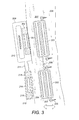
- FIG. 3 shows a cross-sectional view of a different embodiment of an implantable hearing prosthesis.
- FIG. 4 A-B shows examples of arrangements for holding the magnetically opposing internal magnets together.
- Embodiments of the present invention are directed to a magnetic arrangement for an implantable hearing prosthesis system which is compatible with MRI systems.
- FIG. 2 shows a cross-sectional view of an implantable hearing prosthesis arrangement having an implant holding magnet 201 and an implant transducer magnet 202 which are fixable in a common plane beneath the patient skin 207 to underlying skull bone 208 .
- a flexible connector member 206 connects and positions the implant holding magnet 201 and the implant transducer magnet 202 a fixed distance from each other.
- the implant transducer magnet 202 is fixedly secured to the skull bone 208 by a pair of radially opposed bone screws 205 .
- the implant holding magnet 201 and the implant transducer magnet 202 are each enclosed within a titanium housing which contains a pair of internal magnets 203 and 204 in the shape of planar disks that lie in parallel planes which meet along a common junction with repelling like magnetic polarities facing towards each other.
- the internal magnets 203 and 204 within the housing of the implant transducer magnet 202 face each other with south magnetic fields facing towards each other and north magnetic fields facing outward.
- the magnetic polarities of the internal magnets 203 and 204 within the implant holding magnet 201 are reversed from those of the implant transducer magnet 202 so that north magnetic fields face towards each other and south magnetic fields face outward, and the magnet housing holds them together against each other.
- the external elements of the system include a processor lobe 209 and a drive coil lobe 210 connected by a flexible connector 211 .
- the processor lobe 209 contains a signal processor 212 that produces a communications signal to the implanted components and an external holding magnet 213 in the shape of a planar disk having a magnetic polarity opposite to the outermost internal magnet 204 of the implant holding magnet 201 so as to maximize the magnetic attraction between the two.
- the drive coil lobe 210 contains an external drive magnet 214 in the shape of a planar disk having a magnetic polarity opposite to the outermost internal magnet 204 of the implant transducer magnet 202 so as to maximize the magnetic attraction between the two.
- the outermost internal magnet 204 has different directions in the implant holding magnet 201 and the implant transducer magnet 202 , that helps ensure that the processor lobe 209 aligns into proper position directly over the implant holding magnet 201 and the drive coil lobe 210 aligns into proper position over the implant transducer magnet 202 .
- An external drive coil 215 surrounds the outer perimeter of the external drive magnet 214 .
- the external drive coil 215 receives the communications signal produced by the signal processor 212 and produces a corresponding electromagnetic drive signal that travels transcutaneously through the patient skin 207 where it interacts with the magnetic field of the outermost internal drive magnet 204 of the implant transducer magnet 202 . This in turn causes the implant transducer magnet 202 to produce a corresponding mechanical stimulation signal for delivery by bone conduction of the skull bone 208 as an audio signal to the cochlea, which the patient perceives as sound.
- the magnetic polarity of the outermost internal magnet 204 in each of the implant magnets is closer to the skin surface and dominates in the near field so that there is magnetic attraction with the magnets in the external device. But with regards to an external far field magnetic field such as from an MRI, the magnetic polarities of the internal magnets 203 and 204 oppose and cancel each other, as does the opposing overall magnetic polarities of the implant holding magnet 201 and the implant transducer magnet 202 . This net minimizing of the magnetic fields of the implant magnets reduces their magnetic interactions with the external MRI field to minimize adverse effects such as torque forces and imaging artifacts.
- FIG. 3 shows a cross-sectional view of a different embodiment of an implantable hearing prosthesis having a second processor drive coil 302 surrounding a processor drive magnet 301 in the processor lobe 209 of the external device.
- the external device has two external drive coils 214 and 301 respectively, which magnetically interact with their respective implant magnets as shown, each of which generates a portion of the mechanical stimulation signal coupled into the skull bone 208 .
- FIG. 4 A-B shows examples of different arrangements for holding the magnetically opposing internal magnets together.
- FIG. 4A shows an embodiment of an implant magnet 400 where the internal magnets 403 and 404 are enclosed within and held against each other by a titanium housing 402 .
- the embodiment shown also includes a magnet spacer insert 405 that lies along the common junction and separates the internal magnets 403 and 404 , thereby assisting in their easy assembly.
- FIG. 4 B shows another arrangement where a combination of a magnet connector nut 407 and a magnet connector bolt 406 hold the internal magnets 403 and 404 together along their common junction for ease of assembly.
Abstract
Description
Claims (10)
Priority Applications (2)
| Application Number | Priority Date | Filing Date | Title |
|---|---|---|---|
| US13/721,408 US8897475B2 (en) | 2011-12-22 | 2012-12-20 | Magnet arrangement for bone conduction hearing implant |
| US14/547,300 US20150073205A1 (en) | 2011-12-22 | 2014-11-19 | Magnet Arrangement for Bone Conduction Hearing Implant |
Applications Claiming Priority (2)
| Application Number | Priority Date | Filing Date | Title |
|---|---|---|---|
| US201161578953P | 2011-12-22 | 2011-12-22 | |
| US13/721,408 US8897475B2 (en) | 2011-12-22 | 2012-12-20 | Magnet arrangement for bone conduction hearing implant |
Related Child Applications (1)
| Application Number | Title | Priority Date | Filing Date |
|---|---|---|---|
| US14/547,300 Continuation US20150073205A1 (en) | 2011-12-22 | 2014-11-19 | Magnet Arrangement for Bone Conduction Hearing Implant |
Publications (2)
| Publication Number | Publication Date |
|---|---|
| US20130165738A1 US20130165738A1 (en) | 2013-06-27 |
| US8897475B2 true US8897475B2 (en) | 2014-11-25 |
Family
ID=48655241
Family Applications (2)
| Application Number | Title | Priority Date | Filing Date |
|---|---|---|---|
| US13/721,408 Active 2033-01-11 US8897475B2 (en) | 2011-12-22 | 2012-12-20 | Magnet arrangement for bone conduction hearing implant |
| US14/547,300 Abandoned US20150073205A1 (en) | 2011-12-22 | 2014-11-19 | Magnet Arrangement for Bone Conduction Hearing Implant |
Family Applications After (1)
| Application Number | Title | Priority Date | Filing Date |
|---|---|---|---|
| US14/547,300 Abandoned US20150073205A1 (en) | 2011-12-22 | 2014-11-19 | Magnet Arrangement for Bone Conduction Hearing Implant |
Country Status (4)
| Country | Link |
|---|---|
| US (2) | US8897475B2 (en) |
| EP (1) | EP2795927B1 (en) |
| AU (1) | AU2012358871B2 (en) |
| WO (1) | WO2013096559A1 (en) |
Cited By (28)
| Publication number | Priority date | Publication date | Assignee | Title |
|---|---|---|---|---|
| US9022917B2 (en) | 2012-07-16 | 2015-05-05 | Sophono, Inc. | Magnetic spacer systems, devices, components and methods for bone conduction hearing aids |
| US9031274B2 (en) | 2012-09-06 | 2015-05-12 | Sophono, Inc. | Adhesive bone conduction hearing device |
| US9119010B2 (en) | 2011-12-09 | 2015-08-25 | Sophono, Inc. | Implantable sound transmission device for magnetic hearing aid, and corresponding systems, devices and components |
| US9179228B2 (en) | 2011-12-09 | 2015-11-03 | Sophono, Inc. | Systems devices, components and methods for providing acoustic isolation between microphones and transducers in bone conduction magnetic hearing aids |
| US9210521B2 (en) | 2012-07-16 | 2015-12-08 | Sophono, Inc. | Abutment attachment systems, mechanisms, devices, components and methods for bone conduction hearing aids |
| US9258656B2 (en) | 2011-12-09 | 2016-02-09 | Sophono, Inc. | Sound acquisition and analysis systems, devices and components for magnetic hearing aids |
| US9526810B2 (en) | 2011-12-09 | 2016-12-27 | Sophono, Inc. | Systems, devices, components and methods for improved acoustic coupling between a bone conduction hearing device and a patient's head or skull |
| US9736601B2 (en) | 2012-07-16 | 2017-08-15 | Sophono, Inc. | Adjustable magnetic systems, devices, components and methods for bone conduction hearing aids |
| US9788125B2 (en) | 2012-07-16 | 2017-10-10 | Sophono, Inc. | Systems, devices, components and methods for providing acoustic isolation between microphones and transducers in bone conduction magnetic hearing aids |
| US9919154B2 (en) | 2015-12-18 | 2018-03-20 | Advanced Bionics Ag | Cochlear implants having MRI-compatible magnet apparatus and associated methods |
| US10058702B2 (en) | 2003-04-09 | 2018-08-28 | Cochlear Limited | Implant magnet system |
| US10130807B2 (en) | 2015-06-12 | 2018-11-20 | Cochlear Limited | Magnet management MRI compatibility |
| US10300276B2 (en) | 2015-05-28 | 2019-05-28 | Advanced Bionics Ag | Cochlear implants having MRI-compatible magnet apparatus and associated methods |
| US10532209B2 (en) | 2015-12-18 | 2020-01-14 | Advanced Bionics Ag | Cochlear implants having MRI-compatible magnet apparatus and associated methods |
| US10576276B2 (en) | 2016-04-29 | 2020-03-03 | Cochlear Limited | Implanted magnet management in the face of external magnetic fields |
| US10646718B2 (en) | 2016-11-15 | 2020-05-12 | Advanced Bionics Ag | Cochlear implants and magnets for use with same |
| US10646712B2 (en) | 2017-09-13 | 2020-05-12 | Advanced Bionics Ag | Cochlear implants having MRI-compatible magnet apparatus |
| US10806936B2 (en) | 2015-11-20 | 2020-10-20 | Advanced Bionics Ag | Cochlear implants and magnets for use with same |
| US10848882B2 (en) | 2007-05-24 | 2020-11-24 | Cochlear Limited | Implant abutment |
| US10917730B2 (en) | 2015-09-14 | 2021-02-09 | Cochlear Limited | Retention magnet system for medical device |
| US11012797B2 (en) * | 2015-12-16 | 2021-05-18 | Cochlear Limited | Bone conduction device having magnets integrated with housing |
| US11097095B2 (en) | 2017-04-11 | 2021-08-24 | Advanced Bionics Ag | Cochlear implants, magnets for use with same and magnet retrofit methods |
| US11287495B2 (en) | 2017-05-22 | 2022-03-29 | Advanced Bionics Ag | Methods and apparatus for use with cochlear implants having magnet apparatus with magnetic material particles |
| US11364384B2 (en) | 2017-04-25 | 2022-06-21 | Advanced Bionics Ag | Cochlear implants having impact resistant MRI-compatible magnet apparatus |
| US11471679B2 (en) | 2017-10-26 | 2022-10-18 | Advanced Bionics Ag | Headpieces and implantable cochlear stimulation systems including the same |
| US11595768B2 (en) | 2016-12-02 | 2023-02-28 | Cochlear Limited | Retention force increasing components |
| US11638823B2 (en) | 2018-02-15 | 2023-05-02 | Advanced Bionics Ag | Headpieces and implantable cochlear stimulation systems including the same |
| US11792587B1 (en) | 2015-06-26 | 2023-10-17 | Cochlear Limited | Magnetic retention device |
Families Citing this family (13)
| Publication number | Priority date | Publication date | Assignee | Title |
|---|---|---|---|---|
| US20130281764A1 (en) * | 2012-04-19 | 2013-10-24 | Göran Björn | Transcutaneous bone conduction device |
| US9113268B2 (en) * | 2013-04-30 | 2015-08-18 | Vibrant Med-El Hearing Technology Gmbh | Implantable floating mass transducer of a hearing implant system |
| EP2838277B1 (en) | 2013-08-14 | 2016-05-25 | Oticon Medical A/S | Holding unit for a vibration transmitter and a vibration transmission system using it |
| US10091594B2 (en) * | 2014-07-29 | 2018-10-02 | Cochlear Limited | Bone conduction magnetic retention system |
| US10712729B2 (en) * | 2015-04-09 | 2020-07-14 | Panasonic Intellectual Property Management Co., Ltd. | Setting support system for setting operational parameter |
| TWI609589B (en) * | 2015-05-14 | 2017-12-21 | 陳光超 | Hearing auxiliary device and hearing auxiliary processing method |
| US9872115B2 (en) * | 2015-09-14 | 2018-01-16 | Cochlear Limited | Retention magnet system for medical device |
| US10194254B2 (en) * | 2015-12-16 | 2019-01-29 | Cochlear Limited | Isolated actuator for bone conduction device |
| US10207123B2 (en) | 2016-08-30 | 2019-02-19 | National Guard Health Affairs | Skull implanted magnet assembly for brain stimulation |
| US10674287B2 (en) * | 2016-11-23 | 2020-06-02 | Cochlear Limited | Magnet placement and antenna placement of an implant |
| AU2018260607B2 (en) * | 2017-04-24 | 2020-07-23 | Med-El Elektromedizinische Geraete Gmbh | MRI-safety and force optimized implant magnet system |
| CN115003375A (en) * | 2020-02-04 | 2022-09-02 | 科利耳有限公司 | Reversible magnet |
| US11272275B1 (en) | 2020-03-19 | 2022-03-08 | Wisdom Audio Corp. | Magnetic recoil fastener assembly for in-wall speaker installations |
Citations (70)
| Publication number | Priority date | Publication date | Assignee | Title |
|---|---|---|---|---|
| US3487403A (en) | 1965-10-06 | 1969-12-30 | Miniature Elect Components | Electromagnetic indicator having rotating spheres |
| US3573812A (en) | 1967-11-06 | 1971-04-06 | Miniature Elect Components | Electromagnetic indicator |
| US3801767A (en) | 1972-12-11 | 1974-04-02 | R Marks | Pull-apart safety switch with magnetic means for machines |
| US3987967A (en) | 1974-12-19 | 1976-10-26 | Jury Nikolaevich Kuznetsov | Method of working materials and device for effecting same |
| GB1468890A (en) | 1973-04-06 | 1977-03-30 | Lkb Produkter A | Method of and apparatus for moving an object along a surface |
| US4038990A (en) | 1975-11-19 | 1977-08-02 | Medtronic, Inc. | Cautery protection circuit for a heart pacemaker |
| US4199741A (en) | 1976-11-05 | 1980-04-22 | Edouard Serrus Paulet | Moving magnet, rotary switch |
| US4257936A (en) | 1977-09-26 | 1981-03-24 | Yasuji Matsumoto | Self-bonding silicone compositions |
| US4317969A (en) | 1978-09-01 | 1982-03-02 | Hannes Riegler | Electrical line-connector |
| US4549532A (en) | 1983-07-14 | 1985-10-29 | Horst Baermann | Flexible magnetic sheet for therapeutic use |
| US4596971A (en) | 1984-07-26 | 1986-06-24 | Tdk Corporation | Magnetic circuit device |
| US4628907A (en) | 1984-03-22 | 1986-12-16 | Epley John M | Direct contact hearing aid apparatus |
| US4785816A (en) | 1985-01-14 | 1988-11-22 | Johnson & Johnson Ultrasound Inc. | Ultrasonic transducer probe assembly |
| USRE32947E (en) | 1980-09-30 | 1989-06-13 | Baptist Medical Center Of Oklahoma, Inc. | Magnetic transcutaneous mount for external device of an associated implant |
| US4868530A (en) | 1987-01-15 | 1989-09-19 | Tocksfors Verkstads Ab | Electronic switch |
| US4918745A (en) | 1987-10-09 | 1990-04-17 | Storz Instrument Company | Multi-channel cochlear implant system |
| US5015224A (en) | 1988-10-17 | 1991-05-14 | Maniglia Anthony J | Partially implantable hearing aid device |
| SU1690749A1 (en) | 1988-11-15 | 1991-11-15 | Московский Институт Электронного Машиностроения | Device for transmitting a signal to the implantable portion of an artificial ear |
| JPH0423821A (en) | 1990-05-15 | 1992-01-28 | Ind Technol Res Inst | Material having low bromine content for preparing integrated printed circuit layer |
| US5183056A (en) | 1989-10-20 | 1993-02-02 | Siemens Aktiengesellschaft | Inductive motion sensor |
| US5434549A (en) | 1992-07-20 | 1995-07-18 | Tdk Corporation | Moving magnet-type actuator |
| US5456654A (en) | 1993-07-01 | 1995-10-10 | Ball; Geoffrey R. | Implantable magnetic hearing aid transducer |
| US5538219A (en) | 1994-12-16 | 1996-07-23 | Borg-Warner Automotive, Inc. | Reduced noise solenoid valve |
| US5554096A (en) | 1993-07-01 | 1996-09-10 | Symphonix | Implantable electromagnetic hearing transducer |
| US5624376A (en) | 1993-07-01 | 1997-04-29 | Symphonix Devices, Inc. | Implantable and external hearing systems having a floating mass transducer |
| US5630835A (en) | 1995-07-24 | 1997-05-20 | Cardiac Control Systems, Inc. | Method and apparatus for the suppression of far-field interference signals for implantable device data transmission systems |
| WO1997032629A1 (en) | 1996-03-06 | 1997-09-12 | Advanced Bionics Corporation | Magnetless implantable stimulator and external transmitter and implant tools for aligning same |
| US5716407A (en) | 1992-08-24 | 1998-02-10 | Lipomatrix, Incorporated | Method of rendering identifiable a living tissue implant using an electrical transponder marker |
| US5724014A (en) | 1996-04-04 | 1998-03-03 | The Narda Microwave Corporation | Latching RF switch device |
| US5749912A (en) | 1994-10-24 | 1998-05-12 | House Ear Institute | Low-cost, four-channel cochlear implant |
| US5800336A (en) | 1993-07-01 | 1998-09-01 | Symphonix Devices, Inc. | Advanced designs of floating mass transducers |
| US5877664A (en) | 1996-05-08 | 1999-03-02 | Jackson, Jr.; John T. | Magnetic proximity switch system |
| US5897486A (en) | 1993-07-01 | 1999-04-27 | Symphonix Devices, Inc. | Dual coil floating mass transducers |
| US5913815A (en) | 1993-07-01 | 1999-06-22 | Symphonix Devices, Inc. | Bone conducting floating mass transducers |
| WO2000010361A2 (en) | 1998-08-14 | 2000-02-24 | Symphonix Devices, Inc. | Ultrasonic hearing system |
| US6040762A (en) | 1997-05-27 | 2000-03-21 | Tompkins; Eugene | Magnetic switch for automotive security system |
| US6067474A (en) | 1997-08-01 | 2000-05-23 | Advanced Bionics Corporation | Implantable device with improved battery recharging and powering configuration |
| US6175767B1 (en) | 1998-04-01 | 2001-01-16 | James H. Doyle, Sr. | Multichannel implantable inner ear stimulator |
| US6178079B1 (en) | 1996-05-16 | 2001-01-23 | Pacesetter, Inc. | Magnetic annunciator |
| US6178353B1 (en) | 1998-07-27 | 2001-01-23 | Advanced Bionics Corporation | Laminated magnet keeper for implant device |
| US6208882B1 (en) | 1998-06-03 | 2001-03-27 | Advanced Bionics Corporation | Stapedius reflex electrode and connector |
| US6208235B1 (en) | 1997-03-24 | 2001-03-27 | Checkpoint Systems, Inc. | Apparatus for magnetically decoupling an RFID tag |
| US6219580B1 (en) | 1995-04-26 | 2001-04-17 | Advanced Bionics Corporation | Multichannel cochlear prosthesis with flexible control of stimulus waveforms |
| US6292678B1 (en) | 1999-05-13 | 2001-09-18 | Stereotaxis, Inc. | Method of magnetically navigating medical devices with magnetic fields and gradients, and medical devices adapted therefor |
| US6295472B1 (en) | 1998-02-13 | 2001-09-25 | The University Of Iowa Research Foundation | Pseudospontaneous neural stimulation system and method |
| US6313551B1 (en) | 2000-02-04 | 2001-11-06 | Nikon Corporation | Magnet array for a shaft-type linear motor |
| US6348070B1 (en) | 1998-04-17 | 2002-02-19 | Med-El Elektromedizinische Gerate Ges.M.B.H | Magnetic-interference-free surgical prostheses |
| US6358281B1 (en) | 1999-11-29 | 2002-03-19 | Epic Biosonics Inc. | Totally implantable cochlear prosthesis |
| US6505062B1 (en) | 1998-02-09 | 2003-01-07 | Stereotaxis, Inc. | Method for locating magnetic implant by source field |
| US6506987B1 (en) | 2001-07-19 | 2003-01-14 | Randy Woods | Magnetic switch |
| US6522909B1 (en) | 1998-08-07 | 2003-02-18 | Stereotaxis, Inc. | Method and apparatus for magnetically controlling catheters in body lumens and cavities |
| WO2003036560A2 (en) | 2001-10-24 | 2003-05-01 | The Technology Partnership Plc | Sensing apparatus comprising a rolling component |
| WO2003081976A2 (en) | 2002-04-01 | 2003-10-09 | Med-El Elektromedizinische Geräte GmbH | Reducing effect of magnetic and electromagnetic fields on an implants magnet and/or electronic |
| WO2003092326A1 (en) | 2002-04-23 | 2003-11-06 | Cochlear Limited | Mri-compatible cochlear implant |
| WO2004114723A2 (en) | 2003-06-26 | 2004-12-29 | Med-El Elektromedizinische Geraete Gmbh | Electromagnetic transducer with reduced sensitivity to external magnetic fields, and method of improving hearing or sensing vibrations using such a transducer |
| US7190247B2 (en) * | 2002-04-01 | 2007-03-13 | Med-El Elektromedizinische Geraete Gmbh | System and method for reducing effect of magnetic fields on a magnetic transducer |
| US20070191673A1 (en) | 2006-02-14 | 2007-08-16 | Vibrant Med-El Hearing Technology Gmbh | Bone conductive devices for improving hearing |
| US7266209B1 (en) | 2000-01-05 | 2007-09-04 | David William House | Cochlear implants with a stimulus in the human ultrasonic range and method for stimulating a cochlea |
| US20070274551A1 (en) | 2006-05-24 | 2007-11-29 | Chung Yuan Christian University | Implantable Bone-Vibrating Hearing Aid |
| US20080009920A1 (en) * | 2003-04-09 | 2008-01-10 | Cochlear Limited | Implant magnet system |
| US7338035B2 (en) | 2004-12-09 | 2008-03-04 | Chong-Shien Tsai | Foundation shock suppressor |
| US20090209806A1 (en) | 2008-02-20 | 2009-08-20 | Bo Hakansson | Implantable transducer |
| US20090248155A1 (en) * | 2008-03-31 | 2009-10-01 | Cochlear Limited | Transcutaneous magnetic bone conduction device |
| US7608035B2 (en) | 1996-09-10 | 2009-10-27 | Gradient Technologies, Llc | Method and morphologically adaptable apparatus for altering the charge distribution upon living membranes with functional stabilization of the membrane physical electrical integrity |
| US7609061B2 (en) * | 2007-07-13 | 2009-10-27 | Med-El Elektromedizinische Geraete Gmbh | Demagnetized implant for magnetic resonance imaging |
| US20100145135A1 (en) | 2008-12-10 | 2010-06-10 | Vibrant Med-El Hearing Technology Gmbh | Skull Vibrational Unit |
| US20100324355A1 (en) | 2006-12-26 | 2010-12-23 | 3Win N.V. | Device and method for improving hearing |
| US20110022120A1 (en) * | 2009-07-22 | 2011-01-27 | Vibrant Med-El Hearing Technology Gmbh | Magnetic Attachment Arrangement for Implantable Device |
| US20110216927A1 (en) | 2010-03-02 | 2011-09-08 | Vibrant Med-El Hearing Technology Gmbh | Hearing System |
| US8634909B2 (en) * | 2010-04-23 | 2014-01-21 | Med-El Elektromedizinische Geraete Gmbh | MRI-safe disc magnet for implants |
Family Cites Families (3)
| Publication number | Priority date | Publication date | Assignee | Title |
|---|---|---|---|---|
| DK2679025T3 (en) * | 2011-02-24 | 2017-10-23 | Med-El Elektromedizinische Geräte GmbH | MRI-safe actuator for implantable liquid mass transducer |
| WO2013028390A1 (en) * | 2011-08-23 | 2013-02-28 | Torax Medical, Inc. | Medical implant with floating magnets |
| US9736601B2 (en) * | 2012-07-16 | 2017-08-15 | Sophono, Inc. | Adjustable magnetic systems, devices, components and methods for bone conduction hearing aids |
-
2012
- 2012-12-20 AU AU2012358871A patent/AU2012358871B2/en active Active
- 2012-12-20 WO PCT/US2012/070823 patent/WO2013096559A1/en active Application Filing
- 2012-12-20 EP EP12859938.8A patent/EP2795927B1/en active Active
- 2012-12-20 US US13/721,408 patent/US8897475B2/en active Active
-
2014
- 2014-11-19 US US14/547,300 patent/US20150073205A1/en not_active Abandoned
Patent Citations (84)
| Publication number | Priority date | Publication date | Assignee | Title |
|---|---|---|---|---|
| US3487403A (en) | 1965-10-06 | 1969-12-30 | Miniature Elect Components | Electromagnetic indicator having rotating spheres |
| US3573812A (en) | 1967-11-06 | 1971-04-06 | Miniature Elect Components | Electromagnetic indicator |
| US3801767A (en) | 1972-12-11 | 1974-04-02 | R Marks | Pull-apart safety switch with magnetic means for machines |
| GB1468890A (en) | 1973-04-06 | 1977-03-30 | Lkb Produkter A | Method of and apparatus for moving an object along a surface |
| US3987967A (en) | 1974-12-19 | 1976-10-26 | Jury Nikolaevich Kuznetsov | Method of working materials and device for effecting same |
| US4038990A (en) | 1975-11-19 | 1977-08-02 | Medtronic, Inc. | Cautery protection circuit for a heart pacemaker |
| US4199741A (en) | 1976-11-05 | 1980-04-22 | Edouard Serrus Paulet | Moving magnet, rotary switch |
| US4257936A (en) | 1977-09-26 | 1981-03-24 | Yasuji Matsumoto | Self-bonding silicone compositions |
| US4317969A (en) | 1978-09-01 | 1982-03-02 | Hannes Riegler | Electrical line-connector |
| USRE32947E (en) | 1980-09-30 | 1989-06-13 | Baptist Medical Center Of Oklahoma, Inc. | Magnetic transcutaneous mount for external device of an associated implant |
| US4549532A (en) | 1983-07-14 | 1985-10-29 | Horst Baermann | Flexible magnetic sheet for therapeutic use |
| US4549532B1 (en) | 1983-07-14 | 1998-08-11 | Horst Baermann | Flexible magnetic sheet for therapeutic use |
| US4628907A (en) | 1984-03-22 | 1986-12-16 | Epley John M | Direct contact hearing aid apparatus |
| US4596971A (en) | 1984-07-26 | 1986-06-24 | Tdk Corporation | Magnetic circuit device |
| US4785816A (en) | 1985-01-14 | 1988-11-22 | Johnson & Johnson Ultrasound Inc. | Ultrasonic transducer probe assembly |
| US4868530A (en) | 1987-01-15 | 1989-09-19 | Tocksfors Verkstads Ab | Electronic switch |
| US4918745A (en) | 1987-10-09 | 1990-04-17 | Storz Instrument Company | Multi-channel cochlear implant system |
| US5015224A (en) | 1988-10-17 | 1991-05-14 | Maniglia Anthony J | Partially implantable hearing aid device |
| SU1690749A1 (en) | 1988-11-15 | 1991-11-15 | Московский Институт Электронного Машиностроения | Device for transmitting a signal to the implantable portion of an artificial ear |
| US5183056A (en) | 1989-10-20 | 1993-02-02 | Siemens Aktiengesellschaft | Inductive motion sensor |
| JPH0423821A (en) | 1990-05-15 | 1992-01-28 | Ind Technol Res Inst | Material having low bromine content for preparing integrated printed circuit layer |
| US5434549A (en) | 1992-07-20 | 1995-07-18 | Tdk Corporation | Moving magnet-type actuator |
| US5716407A (en) | 1992-08-24 | 1998-02-10 | Lipomatrix, Incorporated | Method of rendering identifiable a living tissue implant using an electrical transponder marker |
| US5624376A (en) | 1993-07-01 | 1997-04-29 | Symphonix Devices, Inc. | Implantable and external hearing systems having a floating mass transducer |
| US5897486A (en) | 1993-07-01 | 1999-04-27 | Symphonix Devices, Inc. | Dual coil floating mass transducers |
| US6475134B1 (en) | 1993-07-01 | 2002-11-05 | Symphonix Devices, Inc. | Dual coil floating mass transducers |
| US5456654A (en) | 1993-07-01 | 1995-10-10 | Ball; Geoffrey R. | Implantable magnetic hearing aid transducer |
| US5554096A (en) | 1993-07-01 | 1996-09-10 | Symphonix | Implantable electromagnetic hearing transducer |
| US6190305B1 (en) | 1993-07-01 | 2001-02-20 | Symphonix Devices, Inc. | Implantable and external hearing systems having a floating mass transducer |
| US5913815A (en) | 1993-07-01 | 1999-06-22 | Symphonix Devices, Inc. | Bone conducting floating mass transducers |
| US5800336A (en) | 1993-07-01 | 1998-09-01 | Symphonix Devices, Inc. | Advanced designs of floating mass transducers |
| US5857958A (en) | 1993-07-01 | 1999-01-12 | Symphonix Devices, Inc. | Implantable and external hearing systems having a floating mass transducer |
| US5749912A (en) | 1994-10-24 | 1998-05-12 | House Ear Institute | Low-cost, four-channel cochlear implant |
| US5538219A (en) | 1994-12-16 | 1996-07-23 | Borg-Warner Automotive, Inc. | Reduced noise solenoid valve |
| US6219580B1 (en) | 1995-04-26 | 2001-04-17 | Advanced Bionics Corporation | Multichannel cochlear prosthesis with flexible control of stimulus waveforms |
| US5630835A (en) | 1995-07-24 | 1997-05-20 | Cardiac Control Systems, Inc. | Method and apparatus for the suppression of far-field interference signals for implantable device data transmission systems |
| WO1997032629A1 (en) | 1996-03-06 | 1997-09-12 | Advanced Bionics Corporation | Magnetless implantable stimulator and external transmitter and implant tools for aligning same |
| US5724014A (en) | 1996-04-04 | 1998-03-03 | The Narda Microwave Corporation | Latching RF switch device |
| US5877664A (en) | 1996-05-08 | 1999-03-02 | Jackson, Jr.; John T. | Magnetic proximity switch system |
| US6178079B1 (en) | 1996-05-16 | 2001-01-23 | Pacesetter, Inc. | Magnetic annunciator |
| US7608035B2 (en) | 1996-09-10 | 2009-10-27 | Gradient Technologies, Llc | Method and morphologically adaptable apparatus for altering the charge distribution upon living membranes with functional stabilization of the membrane physical electrical integrity |
| US6208235B1 (en) | 1997-03-24 | 2001-03-27 | Checkpoint Systems, Inc. | Apparatus for magnetically decoupling an RFID tag |
| US6040762A (en) | 1997-05-27 | 2000-03-21 | Tompkins; Eugene | Magnetic switch for automotive security system |
| US6067474A (en) | 1997-08-01 | 2000-05-23 | Advanced Bionics Corporation | Implantable device with improved battery recharging and powering configuration |
| US6505062B1 (en) | 1998-02-09 | 2003-01-07 | Stereotaxis, Inc. | Method for locating magnetic implant by source field |
| US6295472B1 (en) | 1998-02-13 | 2001-09-25 | The University Of Iowa Research Foundation | Pseudospontaneous neural stimulation system and method |
| US6175767B1 (en) | 1998-04-01 | 2001-01-16 | James H. Doyle, Sr. | Multichannel implantable inner ear stimulator |
| US6348070B1 (en) | 1998-04-17 | 2002-02-19 | Med-El Elektromedizinische Gerate Ges.M.B.H | Magnetic-interference-free surgical prostheses |
| US6208882B1 (en) | 1998-06-03 | 2001-03-27 | Advanced Bionics Corporation | Stapedius reflex electrode and connector |
| US6178353B1 (en) | 1998-07-27 | 2001-01-23 | Advanced Bionics Corporation | Laminated magnet keeper for implant device |
| US6522909B1 (en) | 1998-08-07 | 2003-02-18 | Stereotaxis, Inc. | Method and apparatus for magnetically controlling catheters in body lumens and cavities |
| US6217508B1 (en) | 1998-08-14 | 2001-04-17 | Symphonix Devices, Inc. | Ultrasonic hearing system |
| WO2000010361A2 (en) | 1998-08-14 | 2000-02-24 | Symphonix Devices, Inc. | Ultrasonic hearing system |
| US6292678B1 (en) | 1999-05-13 | 2001-09-18 | Stereotaxis, Inc. | Method of magnetically navigating medical devices with magnetic fields and gradients, and medical devices adapted therefor |
| US6358281B1 (en) | 1999-11-29 | 2002-03-19 | Epic Biosonics Inc. | Totally implantable cochlear prosthesis |
| US7266209B1 (en) | 2000-01-05 | 2007-09-04 | David William House | Cochlear implants with a stimulus in the human ultrasonic range and method for stimulating a cochlea |
| US6313551B1 (en) | 2000-02-04 | 2001-11-06 | Nikon Corporation | Magnet array for a shaft-type linear motor |
| US6506987B1 (en) | 2001-07-19 | 2003-01-14 | Randy Woods | Magnetic switch |
| WO2003036560A2 (en) | 2001-10-24 | 2003-05-01 | The Technology Partnership Plc | Sensing apparatus comprising a rolling component |
| US7190247B2 (en) * | 2002-04-01 | 2007-03-13 | Med-El Elektromedizinische Geraete Gmbh | System and method for reducing effect of magnetic fields on a magnetic transducer |
| US20100004716A1 (en) | 2002-04-01 | 2010-01-07 | Med-El Elektromedizinische Geraete Gmbh | Reducing Effect of Magnetic and Electromagnetic Fields on an Implant's Magnet and/or Electronics |
| US6838963B2 (en) * | 2002-04-01 | 2005-01-04 | Med-El Elektromedizinische Geraete Gmbh | Reducing effects of magnetic and electromagnetic fields on an implant's magnet and/or electronics |
| US20050062567A1 (en) | 2002-04-01 | 2005-03-24 | Med-El Elektromedizinische Geraete Gmbh | Reducing effect of magnetic and electromagnetic fields on an implant's magnet and/or electronics |
| US7091806B2 (en) | 2002-04-01 | 2006-08-15 | Med-El Elektromedizinische Geraete Gmbh | Reducing effect of magnetic and electromagnetic fields on an implant's magnet and/or electronics |
| US20060244560A1 (en) | 2002-04-01 | 2006-11-02 | Med-El Elektromedizinische Geraete Gmbh | Reducing effect of magnetic and electromagnetic fields on an implant's magnet and/or electronics |
| US20040012470A1 (en) | 2002-04-01 | 2004-01-22 | Martin Zimmerling | Reducing effects of magnetic and electromagnetic fields on an implant's magnet and/or electronics |
| US7642887B2 (en) | 2002-04-01 | 2010-01-05 | Med-El Elektromedizinische Geraete Gmbh | System and method for reducing effect of magnetic fields on a magnetic transducer |
| WO2003081976A2 (en) | 2002-04-01 | 2003-10-09 | Med-El Elektromedizinische Geräte GmbH | Reducing effect of magnetic and electromagnetic fields on an implants magnet and/or electronic |
| US7566296B2 (en) | 2002-04-01 | 2009-07-28 | Med-El Elektromedizinische Geraete Gmbh | Reducing effect of magnetic and electromagnetic fields on an implant's magnet and/or electronics |
| WO2003092326A1 (en) | 2002-04-23 | 2003-11-06 | Cochlear Limited | Mri-compatible cochlear implant |
| US20080009920A1 (en) * | 2003-04-09 | 2008-01-10 | Cochlear Limited | Implant magnet system |
| WO2004114723A2 (en) | 2003-06-26 | 2004-12-29 | Med-El Elektromedizinische Geraete Gmbh | Electromagnetic transducer with reduced sensitivity to external magnetic fields, and method of improving hearing or sensing vibrations using such a transducer |
| EP2031896A2 (en) | 2003-06-26 | 2009-03-04 | MED-EL Medical Electronics Elektro-medizinische Geräte GmbH | Electromagnetic transducer with reduced sensitivity to external magnetic fields, and method of improving hearing or sensing vibrations using such a transducer |
| US7338035B2 (en) | 2004-12-09 | 2008-03-04 | Chong-Shien Tsai | Foundation shock suppressor |
| US20070191673A1 (en) | 2006-02-14 | 2007-08-16 | Vibrant Med-El Hearing Technology Gmbh | Bone conductive devices for improving hearing |
| US20070274551A1 (en) | 2006-05-24 | 2007-11-29 | Chung Yuan Christian University | Implantable Bone-Vibrating Hearing Aid |
| US20100324355A1 (en) | 2006-12-26 | 2010-12-23 | 3Win N.V. | Device and method for improving hearing |
| US7609061B2 (en) * | 2007-07-13 | 2009-10-27 | Med-El Elektromedizinische Geraete Gmbh | Demagnetized implant for magnetic resonance imaging |
| US20090209806A1 (en) | 2008-02-20 | 2009-08-20 | Bo Hakansson | Implantable transducer |
| US20090248155A1 (en) * | 2008-03-31 | 2009-10-01 | Cochlear Limited | Transcutaneous magnetic bone conduction device |
| US20100145135A1 (en) | 2008-12-10 | 2010-06-10 | Vibrant Med-El Hearing Technology Gmbh | Skull Vibrational Unit |
| US20110022120A1 (en) * | 2009-07-22 | 2011-01-27 | Vibrant Med-El Hearing Technology Gmbh | Magnetic Attachment Arrangement for Implantable Device |
| US20110216927A1 (en) | 2010-03-02 | 2011-09-08 | Vibrant Med-El Hearing Technology Gmbh | Hearing System |
| US8634909B2 (en) * | 2010-04-23 | 2014-01-21 | Med-El Elektromedizinische Geraete Gmbh | MRI-safe disc magnet for implants |
Non-Patent Citations (18)
| Title |
|---|
| Bromberg & Sunstein LLP, Response A filed May 14, 2007 to Office Action dated Feb. 12, 2007, pertaining to U.S. Appl. No. 11/158,322, 11 pages. |
| Bromberg & Sunstein LLP, Response B filed Jun. 17, 2008 to Office Action dated Mar. 17, 2008, pertaining to U.S. Appl. No. 11/158,322, 10 pages. |
| Bromberg & Sunstein LLP, Response C filed Sep. 19, 2008 to Office Action dated Jun. 26, 2008, pertaining to U.S. Appl. No. 11/671,132, 8 pages. |
| Bromberg & Sunstein LLP, Response D filed Jan. 5, 2009 to Office Action dated Oct. 27, 2008, pertaining to U.S. Appl. No. 11/671,132, 13 pages. |
| European Patent Office, European Search Report (Extended) pertaining to Application No. 08075886.5-2205/12031896, date of mailing Jun. 3, 2009, 8 pages. |
| Heller et al, "Evaluation of MRI Compatibility of the Modified Nucleus Multichannel Auditory Brainstem and Cochlear Implants", The American J. Of Otology 17(5); pp. 724-729 (Sep. 1996). |
| Hobbs, et al, "Magnetic Resonance Image-Guided Proteomics of Human Glioblastoma Multiforme ", Journal of Magnetic Resonance Imaging; pp. 530-536 (2003). |
| Hobbs, et al, "Magnetic Resonance Image—Guided Proteomics of Human Glioblastoma Multiforme ", Journal of Magnetic Resonance Imaging; pp. 530-536 (2003). |
| International Searching Authority, Authorized Officer Lee W. Young, International Search Report and Written Opinion, PCT/US11/41045, mailed Oct. 25, 2011, 10 pages. |
| International Searching Authority, Authorized Officer Shane Thomas, International Search Report and Written Opinion, PCT/US12/70823, date of mailing Mar. 13, 2013, 13 pages. |
| International Searching Authority, International Search Report International Application No. PCT/IB03/02283, date of mailing Nov. 28, 2003, 4 pages. |
| International Searching Authority, Invitation to Pay Additional Fees-International Application No. PCT/IB2004/002588, date of mailing Dec. 20, 2004, 4 pages. |
| International Searching Authority, Invitation to Pay Additional Fees—International Application No. PCT/IB2004/002588, date of mailing Dec. 20, 2004, 4 pages. |
| Teissl et al, "Cochlear Implants: In Vitro Investigation of Electromagnetic Interference at MR Imaging Compatibility and Safety Aspects", Radiology 208(3); pp. 700-708 (Sep. 1998). |
| Teissl et al, "Magnetic Resonance Imaging and Cochlear Implants: Compatibility and Safety Aspects", J. Magn. Reson. Imaging 9(1); pp. 26-38 (Jan. 1999). |
| United States Patent and Trademark Office, Office Action dated Feb. 12, 2007, pertaining to U.S. Appl. No. 11/158,322, 6 pages. |
| United States Patent and Trademark Office, Office Action dated Mar. 17, 2008, pertaining to U.S. Appl. No. 11/158,322, 14 pages. |
| United States Patent and Trademark Office, Office Action dated Oct. 27, 2008, pertaining to U.S. Appl. No. 11/671,132, 7 pages. |
Cited By (38)
| Publication number | Priority date | Publication date | Assignee | Title |
|---|---|---|---|---|
| US10058702B2 (en) | 2003-04-09 | 2018-08-28 | Cochlear Limited | Implant magnet system |
| US11135440B2 (en) | 2003-04-09 | 2021-10-05 | Cochlear Limited | Implant magnet system |
| US11090498B2 (en) | 2003-04-09 | 2021-08-17 | Cochlear Limited | Implant magnet system |
| US10232171B2 (en) | 2003-04-09 | 2019-03-19 | Cochlear Limited | Implant magnet system |
| US10848882B2 (en) | 2007-05-24 | 2020-11-24 | Cochlear Limited | Implant abutment |
| US9119010B2 (en) | 2011-12-09 | 2015-08-25 | Sophono, Inc. | Implantable sound transmission device for magnetic hearing aid, and corresponding systems, devices and components |
| US9179228B2 (en) | 2011-12-09 | 2015-11-03 | Sophono, Inc. | Systems devices, components and methods for providing acoustic isolation between microphones and transducers in bone conduction magnetic hearing aids |
| US9258656B2 (en) | 2011-12-09 | 2016-02-09 | Sophono, Inc. | Sound acquisition and analysis systems, devices and components for magnetic hearing aids |
| US9526810B2 (en) | 2011-12-09 | 2016-12-27 | Sophono, Inc. | Systems, devices, components and methods for improved acoustic coupling between a bone conduction hearing device and a patient's head or skull |
| US9788125B2 (en) | 2012-07-16 | 2017-10-10 | Sophono, Inc. | Systems, devices, components and methods for providing acoustic isolation between microphones and transducers in bone conduction magnetic hearing aids |
| US9210521B2 (en) | 2012-07-16 | 2015-12-08 | Sophono, Inc. | Abutment attachment systems, mechanisms, devices, components and methods for bone conduction hearing aids |
| US9022917B2 (en) | 2012-07-16 | 2015-05-05 | Sophono, Inc. | Magnetic spacer systems, devices, components and methods for bone conduction hearing aids |
| US9736601B2 (en) | 2012-07-16 | 2017-08-15 | Sophono, Inc. | Adjustable magnetic systems, devices, components and methods for bone conduction hearing aids |
| US9031274B2 (en) | 2012-09-06 | 2015-05-12 | Sophono, Inc. | Adhesive bone conduction hearing device |
| US10300276B2 (en) | 2015-05-28 | 2019-05-28 | Advanced Bionics Ag | Cochlear implants having MRI-compatible magnet apparatus and associated methods |
| US11918808B2 (en) | 2015-06-12 | 2024-03-05 | Cochlear Limited | Magnet management MRI compatibility |
| US10130807B2 (en) | 2015-06-12 | 2018-11-20 | Cochlear Limited | Magnet management MRI compatibility |
| US11792587B1 (en) | 2015-06-26 | 2023-10-17 | Cochlear Limited | Magnetic retention device |
| US10917730B2 (en) | 2015-09-14 | 2021-02-09 | Cochlear Limited | Retention magnet system for medical device |
| US11792586B2 (en) | 2015-09-14 | 2023-10-17 | Cochlear Limited | Retention magnet system for medical device |
| US10806936B2 (en) | 2015-11-20 | 2020-10-20 | Advanced Bionics Ag | Cochlear implants and magnets for use with same |
| US11012797B2 (en) * | 2015-12-16 | 2021-05-18 | Cochlear Limited | Bone conduction device having magnets integrated with housing |
| US10821279B2 (en) | 2015-12-18 | 2020-11-03 | Advanced Bionics Ag | Cochlear implants having MRI-compatible magnet apparatus and associated methods |
| US11476025B2 (en) | 2015-12-18 | 2022-10-18 | Advanced Bionics Ag | MRI-compatible magnet apparatus |
| US9919154B2 (en) | 2015-12-18 | 2018-03-20 | Advanced Bionics Ag | Cochlear implants having MRI-compatible magnet apparatus and associated methods |
| US10532209B2 (en) | 2015-12-18 | 2020-01-14 | Advanced Bionics Ag | Cochlear implants having MRI-compatible magnet apparatus and associated methods |
| US10463849B2 (en) | 2015-12-18 | 2019-11-05 | Advanced Bionics Ag | MRI-compatible magnet apparatus and associated methods |
| US10576276B2 (en) | 2016-04-29 | 2020-03-03 | Cochlear Limited | Implanted magnet management in the face of external magnetic fields |
| US10646718B2 (en) | 2016-11-15 | 2020-05-12 | Advanced Bionics Ag | Cochlear implants and magnets for use with same |
| US11595768B2 (en) | 2016-12-02 | 2023-02-28 | Cochlear Limited | Retention force increasing components |
| US11097095B2 (en) | 2017-04-11 | 2021-08-24 | Advanced Bionics Ag | Cochlear implants, magnets for use with same and magnet retrofit methods |
| US11779754B2 (en) | 2017-04-11 | 2023-10-10 | Advanced Bionics Ag | Cochlear implants, magnets for use with same and magnet retrofit methods |
| US11364384B2 (en) | 2017-04-25 | 2022-06-21 | Advanced Bionics Ag | Cochlear implants having impact resistant MRI-compatible magnet apparatus |
| US11752338B2 (en) | 2017-04-25 | 2023-09-12 | Advanced Bionics Ag | Cochlear implants having impact resistant MRI-compatible magnet apparatus |
| US11287495B2 (en) | 2017-05-22 | 2022-03-29 | Advanced Bionics Ag | Methods and apparatus for use with cochlear implants having magnet apparatus with magnetic material particles |
| US10646712B2 (en) | 2017-09-13 | 2020-05-12 | Advanced Bionics Ag | Cochlear implants having MRI-compatible magnet apparatus |
| US11471679B2 (en) | 2017-10-26 | 2022-10-18 | Advanced Bionics Ag | Headpieces and implantable cochlear stimulation systems including the same |
| US11638823B2 (en) | 2018-02-15 | 2023-05-02 | Advanced Bionics Ag | Headpieces and implantable cochlear stimulation systems including the same |
Also Published As
| Publication number | Publication date |
|---|---|
| US20130165738A1 (en) | 2013-06-27 |
| AU2012358871A1 (en) | 2014-07-10 |
| AU2012358871B2 (en) | 2015-06-18 |
| WO2013096559A1 (en) | 2013-06-27 |
| EP2795927A1 (en) | 2014-10-29 |
| EP2795927B1 (en) | 2016-04-06 |
| US20150073205A1 (en) | 2015-03-12 |
| EP2795927A4 (en) | 2015-07-29 |
Similar Documents
| Publication | Publication Date | Title |
|---|---|---|
| US8897475B2 (en) | Magnet arrangement for bone conduction hearing implant | |
| US9549267B2 (en) | Magnet arrangement for bone conduction hearing implant | |
| US8744106B2 (en) | MRI safe actuator for implantable floating mass transducer | |
| US20120029267A1 (en) | Electromagnetic Bone Conduction Hearing Device | |
| US9113268B2 (en) | Implantable floating mass transducer of a hearing implant system | |
| US8774930B2 (en) | Electromagnetic bone conduction hearing device | |
| AU2013312415B2 (en) | Electromagnetic bone conduction hearing device | |
| CN112753232B (en) | Universal bone conduction and middle ear implant | |
| EP3856329A1 (en) | Passive hearing implant |
Legal Events
| Date | Code | Title | Description |
|---|---|---|---|
| AS | Assignment |
Owner name: VIBRANT MED-EL HEARING TECHNOLOGY GMBH, AUSTRIA Free format text: ASSIGNMENT OF ASSIGNORS INTEREST;ASSIGNORS:BALL, GEOFFREY R.;NAGL, MARKUS;SIGNING DATES FROM 20130109 TO 20130112;REEL/FRAME:029653/0666 |
|
| STCF | Information on status: patent grant |
Free format text: PATENTED CASE |
|
| AS | Assignment |
Owner name: MED-EL ELEKTROMEDIZINISCHE GERAETE GMBH, AUSTRIA Free format text: MERGER;ASSIGNOR:VIBRANT MED-EL HEARING TECHNOLOGY GMBH;REEL/FRAME:038533/0834 Effective date: 20160401 |
|
| MAFP | Maintenance fee payment |
Free format text: PAYMENT OF MAINTENANCE FEE, 4TH YEAR, LARGE ENTITY (ORIGINAL EVENT CODE: M1551) Year of fee payment: 4 |
|
| MAFP | Maintenance fee payment |
Free format text: PAYMENT OF MAINTENANCE FEE, 8TH YEAR, LARGE ENTITY (ORIGINAL EVENT CODE: M1552); ENTITY STATUS OF PATENT OWNER: LARGE ENTITY Year of fee payment: 8 |