US8922140B2 - Dual potentiometer address and direction selection for an actuator - Google Patents
Dual potentiometer address and direction selection for an actuator Download PDFInfo
- Publication number
- US8922140B2 US8922140B2 US13/794,232 US201313794232A US8922140B2 US 8922140 B2 US8922140 B2 US 8922140B2 US 201313794232 A US201313794232 A US 201313794232A US 8922140 B2 US8922140 B2 US 8922140B2
- Authority
- US
- United States
- Prior art keywords
- actuator
- address
- potentiometers
- potentiometer
- addresses
- Prior art date
- Legal status (The legal status is an assumption and is not a legal conclusion. Google has not performed a legal analysis and makes no representation as to the accuracy of the status listed.)
- Active, expires
Links
Images


Classifications
-
- G—PHYSICS
- G05—CONTROLLING; REGULATING
- G05B—CONTROL OR REGULATING SYSTEMS IN GENERAL; FUNCTIONAL ELEMENTS OF SUCH SYSTEMS; MONITORING OR TESTING ARRANGEMENTS FOR SUCH SYSTEMS OR ELEMENTS
- G05B15/00—Systems controlled by a computer
- G05B15/02—Systems controlled by a computer electric
-
- G—PHYSICS
- G05—CONTROLLING; REGULATING
- G05B—CONTROL OR REGULATING SYSTEMS IN GENERAL; FUNCTIONAL ELEMENTS OF SUCH SYSTEMS; MONITORING OR TESTING ARRANGEMENTS FOR SUCH SYSTEMS OR ELEMENTS
- G05B19/00—Programme-control systems
- G05B19/02—Programme-control systems electric
- G05B19/04—Programme control other than numerical control, i.e. in sequence controllers or logic controllers
- G05B19/042—Programme control other than numerical control, i.e. in sequence controllers or logic controllers using digital processors
- G05B19/0423—Input/output
-
- G—PHYSICS
- G05—CONTROLLING; REGULATING
- G05B—CONTROL OR REGULATING SYSTEMS IN GENERAL; FUNCTIONAL ELEMENTS OF SUCH SYSTEMS; MONITORING OR TESTING ARRANGEMENTS FOR SUCH SYSTEMS OR ELEMENTS
- G05B2219/00—Program-control systems
- G05B2219/20—Pc systems
- G05B2219/21—Pc I-O input output
- G05B2219/21071—Configuration, each module has a settable address, code wheel, encoder
-
- H04L61/2038—
-
- H—ELECTRICITY
- H04—ELECTRIC COMMUNICATION TECHNIQUE
- H04L—TRANSMISSION OF DIGITAL INFORMATION, e.g. TELEGRAPHIC COMMUNICATION
- H04L61/00—Network arrangements, protocols or services for addressing or naming
- H04L61/50—Address allocation
- H04L61/5038—Address allocation for local use, e.g. in LAN or USB networks, or in a controller area network [CAN]
Definitions
- the present disclosure pertains to control devices and particularly to mechanical movers of devices. More particularly, the disclosure pertains to actuators.
- the disclosure reveals an actuator having two or more potentiometers for setting an address for use with a communications bus or the like.
- An adjustment or setting of the potentiometers may be accessible at two or more sides outside of a housing enclosing the actuator.
- One potentiometer may be set to a direction of control and a range of addresses.
- Another potentiometer may be set to one of several addresses within a range of addresses and direction of control selected on the first potentiometer.
- FIG. 1 is a diagram of two potentiometers used to set an address
- FIG. 2 is a diagram of a structure of an actuator showing internal components of the potentiometers
- FIG. 3 is a diagram of an example layout of actuators and a controller connected to a common bus
- FIG. 4 is a diagram of actuators connected to a controller via a bus and to a roof top unit;
- FIG. 5 is a diagram of an auxiliary switch setpoint control approach
- FIG. 6 is a diagram of an actuator, an economizer and sensor connected to one another via a bus;
- FIG. 7 is a diagram of front and back sides of an actuator revealing certain knobs for control and adjustment such as an address selector being accessible from both sides;
- FIG. 8 is a diagram that shows perspective views of two sides of an actuator revealing the reversibility of actuator position for access to a selector from two sides of the actuator;
- FIG. 9 is a diagram of a close view of a selector or mode switch showing positions available for a test mode and addresses of an actuator
- FIG. 10 is a diagram of a two-wire polarity-insensitive bus controlled actuator
- FIG. 11 is diagram of another layout of another actuator
- FIGS. 12 a through 12 r are schematics of circuitry for the actuator as represented by FIG. 11 .
- the present system and approach may incorporate one or more processors, computers, controllers, user interfaces, wireless and/or wire connections, and/or the like, in an implementation described and/or shown herein.
- This description may provide one or more illustrative and specific examples or ways of implementing the present system and approach. There may be numerous other examples or ways of implementing the system and approach.
- the actuator may typically be located in a difficult space to reach (e.g., in the ceiling or behind equipment).
- Related-art approaches for setting an address may typically be small and difficult to see and actuate (e.g., dip switches/rotary encoders). For instance, using binary methods may require multiple microcontroller input pins.
- Other addressing implementation schemes may be limited in the total number of unique addresses that can be achieved which limits the number of devices that can be used at the same time.
- Another challenge may be a need to be able to select a direction of control at the actuator.
- the present approach may remove various challenges by using a pair of potentiometers to set and establish a network address and the direction of control for a communicating actuator.
- the approach may allow for the address selector to be accessible from two or more sides of the actuator.
- the numbers and interface of the selector may be designed to be large and easy to read.
- An address may be selected using just two analog inputs for a microcontroller. The analog inputs may be converted to digital signals.
- the pair of potentiometers may be used in combination to set the direction of control (“Direct” or “Reverse”) and an address.
- the first potentiometer may be used to select the direction of control and a range of addresses.
- the second potentiometer may be used to select an address from the range selected with the first potentiometer.
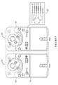
- FIG. 1 is a diagram revealing a front plate 131 and a back plate 132 for an actuator 133 shown in a diagram of FIG. 2 .
- a first potentiometer 134 may have positions for direct and reverse directions of control of actuator 133 .
- Structure 138 of actuator 133 may be secured to a shaft or the like of a mechanism that is moved or controlled in a direct or reverse direction by structure 138 .
- Positions designated for potentiometers 134 and 135 may be labeled on plates 131 and 132 , respectively.
- Positions A, B and C of potentiometer 134 may be for the direct direction of control.
- Positions of potentiometer 134 designated D, E and F may be for the reverse direction of control.
- Positions A and D, B and E, and C and F may represent first, second and third ranges, respectively, for each of both directions of control on potentiometer 134 .
- Potentiometer 135 For each range and direction, an address may be selected by a second potentiometer 135 .
- Potentiometer 135 may have positions designated G, H, I, J and L. These positions may indicate addresses to be selected by the potentiometer.
- the L position for each direction and range may be a test position.
- a table 136 on the front plate 132 and back plate 133 illustrate the available selections for directions, ranges, addresses and tests. Table 136 may be used to determine which setting to use to achieve the desired address.
- Actuator 133 and its potentiometers 134 and 135 may be designed to have more or less than three ranges for each direction, and more or less than five address selections for each range.
- Coupled actuators may be used within heating, ventilating and air-conditioning (HVAC) systems. They may drive final control elements. Example applications may incorporate volume control dampers, mounted directly to the drive shaft of the actuator or remotely with the use of accessory hardware, rotary valves such as ball or butterfly valves mounted directly to the actuator drive shaft, and linear stroke or cage valves mounted with linkages to provide linear actuation.
- the actuator may also be used to operate ventilation flaps, louvers and other devices.
- the actuator may be a spring return device designed for clockwise or counterclockwise fail-safe operation with a continuously engaged mechanical spring. The spring may return the actuator or the mechanism that the actuator is operating to a fail-safe position within a certain time of power loss. An example of the certain time may be 25 seconds.
- the actuator may be mounted to provide clockwise or counterclockwise spring return by flipping or turning the unit over.
- the stroke of the actuator may be adjusted for an application at hand.
- An auxiliary knob may be used to control minimum position or switch position. For switch position, a degree of rotation may be selected for where the switch is desired to activate.
- the actuator may have an override of the control signal for certain applications such as for example freeze protection. The override may move the actuator to a full open or full closed position.
- One instance of position change is that the actuator may be designed to respond to direct digital control (DDC) instantaneous contact closures.
- DDC direct digital control
- FIG. 3 is a diagram of an example layout of actuators 41 , 42 , 43 , 44 and 45 connected to a common bus 46 .
- Bus 46 may be connected to a controller 47 .
- Controller 47 may be SpyderTM controller.
- Bus 46 may be a SylkTM bus.
- the actuators may be ZelixTM actuators.
- the trademark TM items noted in the present description are those of Honeywell International Inc.
- Each actuator may have its open and close speeds individually set by controller 47 via signals on bus 46 .
- actuator 41 may have a speed set to a 90 second timing, actuator 42 a speed set to a 30 second timing; actuator 43 a speed set to a 30 second timing for opening and a 90 second timing for closing, actuator 44 a speed set to a 60 second timing for a normal mode and a 30 second timing for an emergency mode, and actuator 45 a speed set for a 180 second timing.
- the speeds each of the actuators may be set to different timings.
- the respective actuator may be selected according to its address. Fir instance, actuators 41 , 42 , 43 , 44 and 45 may have addresses 11 , 12 , 13 , 14 and 15 , respectively.
- FIG. 4 is a diagram of actuators 41 and 42 connected to controller 47 via bus 46 .
- Actuators 41 and 42 may have connections to a roof top unit (RTU) 48 .
- Actuator 41 may have a variable frequency drive control output of 2 to 10 volts along lines 51 to a component 53 at RTU 48 .
- Actuator 42 may have an auxiliary output binary 24 volts along lines to a component 54 of RTU 48 .
- a present actuator with an auxiliary output may be adjustable via network communications.
- Auxiliary (aux) switches on actuators in some of the related art may have their setpoints established locally on the actuator. Setting an auxiliary switch setpoint may be rather difficult because of an actuator location (e.g., in a ceiling or behind equipment) and in general auxiliary switch setpoint user interfaces may be difficult to set and see (e.g., cam systems, rotating assemblies and adjustable detents) which could lead to setpoint inaccuracies. Also, there may be a fixed hysteresis with each of these solutions.
- an aux switch may be set to make or break at around 45 degrees of the actuator's stroke. If set for 45 degrees, the aux switch may virtually always trip at that position and can not necessarily be changed without a service technician physically changing the setpoint.
- Some applications would benefit by having the aux switch make at 20 degrees while opening, and break at 60 degrees while closing, or 20 degrees during a heat mode and 45 degrees during a cool mode, or vice versa.
- aux switches of the related art may only be able to change state based on an actuator shaft position. There may be many applications where switching the aux switch based on temperature or some other variable (or combination of variables) would be beneficial.
- the present approach may solve the issues by allowing the auxiliary switch setpoint and control parameters to be configured remotely over the bus in real time.
- This approach may be implemented with digital or analog outputs and there could be a multiple setpoint per relay solution.
- the present approach may be effected by enhancing the software in the controller and communicating actuator systems. It may be used by allowing the auxiliary switch parameters to be programmable via a higher order controller.
- An example may incorporate using a Jade controller or SpyderTM controller with NiagaraTM (or fishsimTM) to program the functionality of a SylkTM ZelixTM communicating actuator over a SylkTM bus.
- a SylkTM bus may be a two-wire, polarity insensitive bus that may provide communications between a SylkTM-enabled actuator and a SylkTM-enabled controller.
- An example of the SylkTM bus circuitry may be disclosed in U.S. Pat. No. 7,966,438, issued Jun. 21, 2011, and entitled “Two-wire Communications Bus System”.
- U.S. Pat. No. 7,966,438, issued Jun. 21, 2011, is hereby incorporated by reference.
- FIG. 5 is a diagram of an auxiliary switch control approach.
- Symbol 11 may indicate an auxiliary position change which may be initiated.
- An auxiliary switch setpoint may be controlled manually by an auxiliary potentiometer in symbol 12 .
- Symbol 13 indicates that if the current actuator position is greater than the setpoint set by the auxiliary potentiometer, then the auxiliary switch may be activated. If not, then the auxiliary switch may be deactivated.
- the auxiliary switch setpoint may be controlled by an external controller command.
- Symbol 15 indicates that if the current actuator position is greater than the setpoint set by an external controller command, then the auxiliary switch may be activated. If not, then the auxiliary switch may be deactivated.
- a present communicating actuator may have a network adjustable running time. Applications in the field may require or benefit from different running time actuators.
- different running time actuators might be purchased by model number, or programmable actuators may be programmed at commissioning using an independent tool. This situation may dictate that a person pick one running time for the actuator and application at the beginning of an implementation of the actuator.
- An example of an issue of running time may occur during system checkout in an OEM factory or in the field.
- An OEM or field technician may prefer a fast running time (10 seconds) so that the actuator system can be checked out quickly without having to wait for a 90 second actuator to run its time.
- the present approach may incorporate an actuator that allows programmable running time via the local bus.
- the actuator's running time may be programmed to different values at different times during the actuator's lifecycle. For example, the actuator may be programmed for 15 second timing during a test, 30 second timing during a normal application mode, and 90 second timing during a saver mode.
- the present actuator approach may be applied in a JadeTM economizer/SylkTM ZelixTM system implementation.
- SylkTM bus hardware may be implemented on the controller and the actuator.
- firmware in these products may be created to implement the adjustable running time functionality.
- FIG. 6 is a diagram of a ZelixTM actuator 21 with Jade economizer 22 connected to the actuator via a SylkTM bus 23 .
- a sensor 24 may be connected into the SylkTM bus.
- a present approach may incorporate a potentiometer address selection for an actuator. Setting a network address on a communicating actuator may be rather difficult.
- the actuator may be typically located in a hard to reach area (e.g., in a ceiling or behind equipment).
- Related art approaches may involve actuators that are typically small and hard to see and actuate (e.g., with dip switches/rotary encoders) and may use binary techniques as described herein which may require multiple microcontroller input pins.
- the present approach may solve the issue by using a potentiometer to set and establish a network address on a communication actuator.
- the approach may allow for an address selector to be accessible from both sides of the actuator using a single potentiometer, the numbers and interface to be large and easy to read, and it may allow the address to be selected using only one analog input on the microcontroller.
- FIG. 7 is a diagram of a front view 31 of an actuator 33 and a back view 32 of the actuator.
- Certain knobs for control and adjustment such as an address selector 34 may be accessible from both sides of actuator 33 .
- Selector 34 may have five positions for address selection. For instance, a position 1 may be for selecting an address 11 , position 2 for address 12 , position 3 for address 13 , position 4 for address 14 and position 5 for address 15 .
- a position 6 may be for selecting a test mode.
- FIG. 8 is a diagram that shows perspective views of sides 31 and 32 of actuator 33 revealing the reversibility of the actuator for access to selector 34 from both sides of actuator 33 .
- the present approach may incorporate an actuator which has accessible onboard diagnostics.
- An issue in the related art may be that actuators in the field can fail or malfunction and of which many cases may be undetected. Such actuators may be wasting energy or giving up comfort for years before the failure is found.
- the present approach may solve this issue by communicating alarms, status and diagnostics automatically over a bus. If an actuator fails, an alarm may be sent to the higher order controller for immediate notification.
- These software alarms and diagnostic features may be implemented in the firmware for a SylkTM ZelixTM communicating actuator.
- a controller or processor may provide on the communications bus one or more diagnostics items of a group consisting of high temperature warning, excessive noise on power line, record/report back electromotive force (EMF) on spring return, percentage of life detection, high amount of travel for given amount of time, hunting around a given point, actuator angle, communication normal indicator, stroke limiting, control valve (Cv) selection, flowrate on pressure independent control valve (PIC-V), set auxiliary switch, report auxiliary switch setting, report auxiliary switch status, report auxiliary switch current draw—auxiliary equipment status, if switch drives fan—verify fan shuts down before damper closes, if switch drives coils—verify heat exchanger running before opening/closing valve, report stuck valve/damper, PIC-V constant pressure—constant torque, changeover valve—no cycling for a period of time, time since last movement, date/time of first operation (commissioning), audible/detectable signal for location, device in warranty, device model number/serial number/date code, device type—outside air damper
- the present approach may incorporate an actuator test mode.
- an actuator installer may be several approaches used by an actuator installer to verify that an actuator has been installed correctly.
- One approach may involve an operator at the control panel to cause the actuator to open and close.
- the installer or maintainer may have access the connector and short the modulating input to cause the actuator to open, thus verifying that the actuator is working and connected properly.
- test mode there may be a test mode selection on a pot or switch that causes the actuator to move to its open position. An installer or maintainer may then just select Test Mode via the pot and verify an operation of the actuator without needing to access the connector or to communicate with a control operator.
- Actuator software may verify that the test mode has been selected on the switch or potentiometer. The software may then exercise the following algorithm.
- FIG. 9 is a diagram of a closer view of the selector or mode switch 34 , showing 6 positions available for the test mode of actuator 33 .
- a mode plate 35 indicates that position 6 may be designated for “Test” or test mode.
- Positions 1-5 indicate five different addresses available for selection by switch 34 .
- FIG. 10 is a diagram of a two-wire polarity-insensitive bus (i.e., SylkTM) controlled actuator 61 .
- An electric motor 62 may drive a gear train 63 which turns an actuator shaft 64 which may move a damper, valve, or other component.
- a processor 65 may be connected to motor 62 and provide control of the motor. Motor 62 may instead be some other electromagnetic mover.
- Processor 65 may also be connected to a communications bus 66 .
- a shaft position potentiometer 67 may be mechanically connected to the actuator shaft 64 or a part on the gear train to electrically provide a position of shaft 64 to processor 65 .
- An auxiliary switch output 68 and an analog output 69 may be provided by processor 65 .
- a user interface 71 may provide a bus address select to processor 65 .
- a user interface 72 may provide a manual auxiliary switch trigger select.
- Actuator 61 may be connected to other devices 73 such as actuators, sensors, controllers, and so on. Actuator 61 may have a power supply 74 to power its components. An AC power line 75 or other source may provide power to supply 74 .
- FIG. 11 is a diagram of an actuator 120 .
- Many components of actuator 120 are revealed in the diagrams shown in FIGS. 12 a through 12 r . Interconnections of the components may be indicated in the diagrams as identified by various connections and wires having labels and alphanumeric symbols.
- a line identified as A1 in FIG. 12 a may be connected to a line identified as A1 in FIG. 12 b .
- a processor 101 may be connected to power supply electronics 105 , bus electronics and isolation transformer 109 , a motor control 103 and a shaft position indicator 102 .
- Processor 101 may also be connected to an auxiliary switch 108 , an auxiliary switch and position potentiometer 110 , and a user address and auxiliary switch selector 107 . Further, processor 101 may be connected to an analog out 106 and functional test electronics 104 .
- a motor 112 may be connected to motor control 103 .
- An output of motor 112 may be mechanically connected to a gear reduction train 113 .
- Gear train 113 may have an actuator coupling or shaft 114 for connection to a mechanically controlled or operated device 115 such as, for example, a damper, valve, flap, louver, and so on.
- Gear train 113 may be connected to shaft position indicator 102 .
- Bus electronics and isolation transformer 109 may be connected to a communications bus 116 .
- Outside actuator 120 , bus 116 may be connected to controllers 117 , sensors 118 , actuators 119 , and other devices 121 and various communication media 122 .
- An outside power source 123 may be connected to power supply electronics.
- Processor 101 may be shown in a diagram of FIG. 12 a .
- Shaft position indicator 102 may be shown in a diagram of FIG. 12 b .
- Motor control 103 may be shown in diagrams of FIGS. 12 c , 12 d and 12 e .
- Functional test electronics may be shown in a diagram of FIG. 12 f .
- Power supply electronics may be shown in diagrams of FIGS. 12 g and 10 h .
- Analog out electronics 106 may be shown in diagrams of FIGS. 12 i and 12 j .
- User address and auxiliary switch circuitry 107 may be shown in diagrams of FIG. 12 k .
- Auxiliary switch circuitry 108 may be shown in a diagram of FIG. 121 .
- Communications bus electronics 109 may be shown in diagrams of FIGS. 12 m , 12 n , 12 o and 12 p .
- Auxiliary switch and position potentiometer circuitry 110 may be shown in a diagram of FIG. 12 q .
- Miscellaneous circuitry 125 such as thermistor, oscillator and flash electronics may be in diagrams of FIG. 12 r .
- an actuator system for a heating, ventilating and air conditioning (HVAC) setup may incorporate an electromechanical mover, a processor connected to the electromechanical mover, and a first potentiometer, having a set of directions of control and a plurality of ranges for addresses, connected to the processor, a second potentiometer having a plurality of addresses connected to the processor, and a housing that encloses the actuator. Access to the potentiometers for selecting or changing an address for the actuator may be available on at least two sides of the housing. The at least two sides of the housing may reveal visible indications and physical features for selecting or changing an address for the actuator on the potentiometers.
- An address for the actuator may incorporate a direction of control selected from the set of directions of control on the first potentiometer, a range of addresses selected from the plurality of ranges on the first potentiometer, and an address selected from the plurality of addresses on the second potentiometer within the range of addresses selected from the plurality of ranges for addresses.
- the actuator may be connected to a communications bus.
- the address for the actuator may be an address of the actuator used on the communications bus.
- the actuator system may further incorporate one or more additional actuators connected to the communications bus.
- Each actuator may have an address which is different from an address of the other one or more additional actuators connected to the communications bus.
- an address for the replacement actuator may be selected or changed via first and second potentiometers of the replacement actuator to be the same as the address of the actuator being replaced.
- the actuator system may further incorporate a controller connected to the communications bus.
- the communications bus may have two polarity-insensitive wires.
- the controller may override a setting of the plurality of settings of the potentiometers which is a selection of an address for the actuator and can select another or the same address for the actuator via the communications bus.
- An address may define an actuator in terms of one or more items of a group consisting of an activation program, actuator stroke speeds, one or more sensor outputs, input/output requirements, a slot assignment on the communications bus, one or more parameters of the actuator, and a sensor prioritization.
- An approach for establishing an address for an actuator in a heating, ventilating and air conditioning (HVAC) system may incorporate providing an address for an HVAC actuator on a communications bus by providing an input to the processor, connecting the processor to an electromagnetic mover, and connecting the electromagnetic mover to an HVAC actuator shaft coupling.
- the input to the processor may have an address for the HVAC actuator provided by selections made on first and second potentiometers.
- the first and second potentiometers may have a plurality of selections for providing inputs to the processor.
- An address for the actuator may incorporate a selection of a direction of control from the set of directions of control, a range of addresses from the plurality of ranges on the first potentiometer, and an address from the plurality of addresses on the second potentiometer.
- the inputs may have different addresses for the actuator on the communications bus.
- the actuator shaft coupling may mechanically operate an apparatus in an HVAC system.
- the approach may further incorporate enclosing the processor, the electromagnetic mover, and the first and second potentiometers in a housing.
- the housing may provide access to the first and second potentiometers for selecting the address for the actuator at two or more sides on the housing.
- the approach may further incorporate replacing the actuator with a second HVAC actuator, and setting the first and second potentiometers of the second actuator to an address setting that is the same as an address setting of the replaced actuator or different from any other address on the communications bus.
- the communications bus may be a polarity-insensitive two-wire system.
- An actuator for a heating, ventilating and air conditioning (HVAC) system may incorporate an output shaft coupling, an electromagnetic mover mechanically connected to the output shaft coupling, a processor connected to the electromagnetic mover, a first potentiometer, having a set of directions of control and a plurality of ranges for addresses, connected to the processor, and a second potentiometer having a plurality of addresses, connected to the processor.
- HVAC heating, ventilating and air conditioning
- An address for the actuator may incorporate a selection of a direction of control from the set of directions of control, a range of addresses from the plurality of ranges on the first potentiometer, and an address from the plurality of addresses on the second potentiometer.
- the processor may be connected to a communications bus.
- the address for the actuator may be on the communications bus. Other addresses on the communications bus may be for other actuators.
- the communications bus may have two polarity-insensitive wires.
- the actuator may further incorporate a housing that encloses the electromagnetic mover, the processor, and the first and second potentiometers.
- the first and second potentiometers may be accessible on at least two sides of the housing for selecting an address for the actuator on the first and second potentiometers.
- An address setting of the first and second potentiometer may be an analog input to the processor.
- the first and second potentiometers may be voltage dividers for a selection of an address as an analog input.
- the analog input may be converted into a digital signal at the processor.
- Replacing the actuator with a substitute actuator having first and second potentiometers may incorporate selecting an address for the substitute actuator by making selections on the first and second potentiometers of substitute actuator.
- the substitute actuator may have an address which is the same as the address of the actuator being replaced.
Abstract
Description
Claims (20)
Priority Applications (1)
| Application Number | Priority Date | Filing Date | Title |
|---|---|---|---|
| US13/794,232 US8922140B2 (en) | 2011-11-09 | 2013-03-11 | Dual potentiometer address and direction selection for an actuator |
Applications Claiming Priority (2)
| Application Number | Priority Date | Filing Date | Title |
|---|---|---|---|
| US13/293,041 US9041319B2 (en) | 2011-11-09 | 2011-11-09 | Actuator having an address selector |
| US13/794,232 US8922140B2 (en) | 2011-11-09 | 2013-03-11 | Dual potentiometer address and direction selection for an actuator |
Related Parent Applications (1)
| Application Number | Title | Priority Date | Filing Date |
|---|---|---|---|
| US13/293,041 Continuation-In-Part US9041319B2 (en) | 2011-11-09 | 2011-11-09 | Actuator having an address selector |
Publications (2)
| Publication Number | Publication Date |
|---|---|
| US20140142758A1 US20140142758A1 (en) | 2014-05-22 |
| US8922140B2 true US8922140B2 (en) | 2014-12-30 |
Family
ID=50728701
Family Applications (1)
| Application Number | Title | Priority Date | Filing Date |
|---|---|---|---|
| US13/794,232 Active 2032-03-04 US8922140B2 (en) | 2011-11-09 | 2013-03-11 | Dual potentiometer address and direction selection for an actuator |
Country Status (1)
| Country | Link |
|---|---|
| US (1) | US8922140B2 (en) |
Cited By (2)
| Publication number | Priority date | Publication date | Assignee | Title |
|---|---|---|---|---|
| US20190247689A1 (en) * | 2018-02-12 | 2019-08-15 | Tyco Fire Products Lp | Microwave fire protection devices |
| US20190247690A1 (en) * | 2018-02-12 | 2019-08-15 | Tyco Fire Products Lp | Microwave fire protection systems and methods |
Families Citing this family (3)
| Publication number | Priority date | Publication date | Assignee | Title |
|---|---|---|---|---|
| US9939825B2 (en) * | 2014-09-02 | 2018-04-10 | Johnson Controls Technology Company | HVAC actuator with line voltage input |
| US11609589B2 (en) * | 2014-09-02 | 2023-03-21 | Johnson Controls Tyco IP Holdings LLP | HVAC actuator with automatic line voltage input selection |
| FR3033106B1 (en) | 2015-02-23 | 2017-02-24 | Somfy Sas | METHOD FOR MANAGING A DOMOTIC FACILITY FACILITATING THE REPLACEMENT OF AN EQUIPMENT |
Citations (143)
| Publication number | Priority date | Publication date | Assignee | Title |
|---|---|---|---|---|
| GB1172789A (en) | 1967-10-03 | 1969-12-03 | Ibm | Digital Address Generator. |
| US3829848A (en) | 1971-03-29 | 1974-08-13 | Industrial Nucleonics Corp | Stuck actuator alarm |
| US4129847A (en) | 1977-06-06 | 1978-12-12 | Robertshaw Controls Company | Cut-back thermostat construction |
| US4302931A (en) | 1980-06-16 | 1981-12-01 | Cnandler Evans Inc. | Fuel flow limiting device for overspeed and overtemperature control |
| JPS5786544U (en) | 1980-11-18 | 1982-05-28 | ||
| JPS6091411U (en) | 1983-11-29 | 1985-06-22 | 豊田 襄 | U-shaped groove formwork |
| US4549446A (en) | 1984-02-06 | 1985-10-29 | Johnson Service Company | Motorized valve actuator |
| US4628268A (en) | 1982-11-18 | 1986-12-09 | Mitsubishi Denki Kabushiki Kaisha | Test device for testing an actuator circuit |
| US4652417A (en) | 1985-02-07 | 1987-03-24 | Westinghouse Electric Corp. | Fault-tolerant analog output network |
| US4673920A (en) | 1984-05-11 | 1987-06-16 | General Signal Corporation | Fire alarm control and emergency communication system |
| US4688183A (en) | 1984-12-24 | 1987-08-18 | United Technologies Corporation | Fire and security system with multi detector-occupancy-temperature-smoke (MDOTS) sensors |
| US4742475A (en) | 1984-06-19 | 1988-05-03 | Ibg International, Inc. | Environmental control system |
| JPS63257802A (en) | 1987-04-15 | 1988-10-25 | Omron Tateisi Electronics Co | Device for diagnosing failure of external apparatus for programmable controller |
| US4794314A (en) | 1987-08-28 | 1988-12-27 | Johnson Service Company | Environmental position actuator apparatus having load responsive limit control apparatus |
| US4795867A (en) | 1986-01-17 | 1989-01-03 | Diesel Kiki Co., Ltd. | Motor actuator for air conditioning system |
| US4854852A (en) | 1987-09-21 | 1989-08-08 | Honeywell Inc. | System for redundantly processing a flame amplifier output signal |
| US5025206A (en) | 1989-09-25 | 1991-06-18 | General Electric Company | Test mode actuator and indicator for electronic energy meter |
| US5081405A (en) * | 1991-04-01 | 1992-01-14 | Honeywell Inc. | Electrical actuator with means for preventing dither at a limit switch |
| US5153493A (en) | 1991-02-04 | 1992-10-06 | Barber-Colman Company | Non-bridge type electronic actuator control |
| US5159534A (en) | 1991-01-22 | 1992-10-27 | Johnson Service Company | Electronic/electromechanical packaging arrangement for facility management system |
| EP0511828A2 (en) | 1991-04-30 | 1992-11-04 | Oki Electric Industry Co., Ltd. | Alarm control method for detecting abnormality in a drive circuit of an actuator |
| US5180959A (en) * | 1991-08-08 | 1993-01-19 | Eaton Corporation | Electrically controlled shift actuator |
| US5318516A (en) | 1990-05-23 | 1994-06-07 | Ioan Cosmescu | Radio frequency sensor for automatic smoke evacuator system for a surgical laser and/or electrical apparatus and method therefor |
| US5416781A (en) | 1992-03-17 | 1995-05-16 | Johnson Service Company | Integrated services digital network based facility management system |
| US5422553A (en) | 1984-12-04 | 1995-06-06 | United Technologies Corporation | Servo actuator diagnostic monitoring |
| US5431182A (en) | 1994-04-20 | 1995-07-11 | Rosemount, Inc. | Smart valve positioner |
| US5446677A (en) | 1994-04-28 | 1995-08-29 | Johnson Service Company | Diagnostic system for use in an environment control network |
| US5454273A (en) | 1994-02-09 | 1995-10-03 | Westinghouse Electric Corporation | Motor operated valve actuator diagnostic system and test stand |
| US5465031A (en) | 1985-04-01 | 1995-11-07 | Nilssen; Ole K. | Programmable actuator for light dimmer |
| US5584319A (en) | 1995-07-24 | 1996-12-17 | J. M. Cholin Consultants, Inc. | Electro-optical valve-status supervision switch circuit for fire protection |
| US5621398A (en) | 1995-08-07 | 1997-04-15 | Saint Switch, Inc. | Programmable switch |
| US5682329A (en) | 1994-07-22 | 1997-10-28 | Johnson Service Company | On-line monitoring of controllers in an environment control network |
| US5711480A (en) | 1996-10-15 | 1998-01-27 | Carrier Corporation | Low-cost wireless HVAC systems |
| US5744925A (en) | 1996-09-16 | 1998-04-28 | Delco Electronics Corporation | Control method and apparatus for two-wire motor actuator |
| US5848609A (en) | 1996-11-26 | 1998-12-15 | Worcester Control Licenseco Inc. | Digital valve positioner |
| US6025788A (en) | 1995-11-24 | 2000-02-15 | First Smart Sensor Corp. | Integrated local or remote control liquid gas leak detection and shut-off system |
| US6035878A (en) | 1997-09-22 | 2000-03-14 | Fisher Controls International, Inc. | Diagnostic device and method for pressure regulator |
| US6051948A (en) | 1998-11-13 | 2000-04-18 | Honeywell Inc. | Bidirectional positioning actuator with limited positioning range |
| US6059046A (en) | 1998-03-05 | 2000-05-09 | Grunau Company, Inc. | Low pressure carbon dioxide fire protection system for semiconductor fabrication facility |
| US6121735A (en) | 1994-03-10 | 2000-09-19 | Igeta; Tamotsu | Actuator with start-stop operation |
| US6178997B1 (en) | 1997-09-22 | 2001-01-30 | Fisher Controls International, Inc. | Intelligent pressure regulator |
| US6249100B1 (en) | 1997-07-31 | 2001-06-19 | Honeywell International Inc. | Drive circuit and method for an electric actuator with spring return |
| US6415617B1 (en) | 2001-01-10 | 2002-07-09 | Johnson Controls Technology Company | Model based economizer control of an air handling unit |
| US6431231B1 (en) | 2000-06-16 | 2002-08-13 | Clark Equipment Company | Hydraulically controlled stump grinder |
| US6431203B1 (en) | 1999-02-01 | 2002-08-13 | Honeywell International Inc. | Actuator mounting assembly |
| US6443422B1 (en) | 2001-06-08 | 2002-09-03 | Eaton Corporation | Apparatus and method for adjusting an actuator on a real-time basis |
| US20020152298A1 (en) | 2001-01-12 | 2002-10-17 | Christopher Kikta | Small building automation control system |
| US6505991B2 (en) | 2001-03-21 | 2003-01-14 | Honeywell International Inc. | Self-centering shaft adapter |
| EP1170036A3 (en) | 2000-07-08 | 2003-01-22 | KIDDE-DEUGRA Brandschutzsysteme GmbH | Method and apparatus for fire-fighting |
| US20030018398A1 (en) | 2001-07-02 | 2003-01-23 | Juntunen Robert D. | Control system apparatus and method using a controlled device for manual data entry |
| US20030052180A1 (en) | 2001-09-19 | 2003-03-20 | Trw Inc. | Method and apparatus for establishing addresses for plural actuators connected to a bus |
| US20030178257A1 (en) | 2002-03-20 | 2003-09-25 | Invensys Building Systems Inc. | Manual override and locking mechanism and actuator including same |
| US6651952B1 (en) | 1998-11-12 | 2003-11-25 | Barber Colman Company | Two position rotary actuator incorporating DC solenoid |
| US20040124797A1 (en) | 2002-12-16 | 2004-07-01 | Tokuhisa Takeuchi | Electric actuator system |
| US20040212336A1 (en) | 2003-04-24 | 2004-10-28 | Mcmillan Scott D. | Spring return actuator for a damper |
| DE202004011803U1 (en) | 2004-07-28 | 2004-12-09 | Allnet Gmbh | Remote monitoring device for actuators and sensors, has drivers coupled to respective bus interfaces, and short-circuit monitoring circuits which transmit signal to control device |
| US6838988B2 (en) | 2003-04-30 | 2005-01-04 | Digital Security Controls Ltd. | Smoke detector with performance reporting |
| US6851620B2 (en) | 2003-04-30 | 2005-02-08 | Invensys Building Systems, Inc. | Floating actuator control system and method |
| US20050127861A1 (en) | 2003-12-11 | 2005-06-16 | Mcmillan Scott D. | Electric motor with speed control |
| US6915171B2 (en) | 2001-04-26 | 2005-07-05 | Visteon Global Technologies, Inc. | Automatic procedure for locating actuator addresses on a bus system |
| US6922123B2 (en) | 2002-11-19 | 2005-07-26 | Delphi Technologies, Inc. | Magnetic detent action for switches |
| US20060035580A1 (en) | 2004-07-29 | 2006-02-16 | Anderson Dean B | Damper actuator assembly |
| US7021072B2 (en) | 2003-04-24 | 2006-04-04 | Honeywell International Inc. | Current control loop for actuator and method |
| US7024282B2 (en) | 2002-09-26 | 2006-04-04 | Siemens Building Technologies, Inc. | Multi-node utilization of a single network variable input for computation of a single control variable at a sink node |
| US7031880B1 (en) | 2004-05-07 | 2006-04-18 | Johnson Controls Technology Company | Method and apparatus for assessing performance of an environmental control system |
| US7033268B2 (en) | 2003-04-17 | 2006-04-25 | Siemens Building Technologies, Inc. | Multi-mode damper actuator |
| US7058542B2 (en) | 2000-07-07 | 2006-06-06 | Metso Automation Oy | Wireless diagnostic system in industrial processes |
| US20060130502A1 (en) | 2004-12-16 | 2006-06-22 | Wruck Richard A | Virtual controller for mixed air low temperature protection of HVAC systems |
| US7066273B2 (en) | 2001-04-06 | 2006-06-27 | Benjamin Tan | Apparatus and methods for sensing of fire and directed fire suppression |
| US7079831B2 (en) | 2001-06-04 | 2006-07-18 | Strategic Vista International Inc. | Method and apparatus for two-way communications amongst a plurality of communications devices |
| US7105949B2 (en) | 2004-01-22 | 2006-09-12 | Delta Electronics, Inc. | Emergent power supply system and method of achieving input current balance in such system |
| US7188481B2 (en) | 2002-10-30 | 2007-03-13 | Honeywell International Inc. | Adjustable damper actuator |
| US20070120664A1 (en) | 2005-11-30 | 2007-05-31 | Syncro Corporation | Fire hydrant locating system |
| US7241218B2 (en) | 2003-05-06 | 2007-07-10 | Ruskin Company | Fire/smoke damper control system |
| US20070176570A1 (en) | 2006-01-30 | 2007-08-02 | Honeywell International Inc. | Inverter loop latch with integrated ac detection reset |
| US7265512B2 (en) | 2005-08-30 | 2007-09-04 | Honeywell International Inc. | Actuator with feedback for end stop positioning |
| US20070226318A1 (en) | 2006-02-21 | 2007-09-27 | Rydberg Kris M | System, method, and device for communicating between a field device, device controller, and enterprise application |
| US20080051024A1 (en) | 2006-08-25 | 2008-02-28 | Siemens Building Technologies, Inc. | Damper actuator assembly with speed control |
| EP1901145A2 (en) | 2006-08-23 | 2008-03-19 | MicroNet Sensorik GmbH | Field device and method of operating the same |
| US20080111512A1 (en) | 2006-11-09 | 2008-05-15 | Honeywell International Inc. | Actuator position switch |
| US7378980B2 (en) | 2004-09-29 | 2008-05-27 | Siemens Building Technologies, Inc. | Triangulation of position for automated building control components |
| US7401541B2 (en) | 2004-08-20 | 2008-07-22 | Enfield Technlogies, Llc | Servo-pneumatic actuator |
| US20080244104A1 (en) | 2007-03-28 | 2008-10-02 | Johnson Controls Technology Company | Building automation system field devices and adapters |
| US20080258253A1 (en) | 2003-10-08 | 2008-10-23 | Wolfgang Fey | Integrated Microprocessor System for Safety-Critical Regulations |
| US7442068B2 (en) | 2004-09-24 | 2008-10-28 | Siemens Schweiz Ag | Electrical device having a base and an electrical module |
| US7446494B2 (en) | 2006-10-10 | 2008-11-04 | Honeywell International Inc. | HVAC actuator having torque compensation |
| US7451759B2 (en) | 2004-05-04 | 2008-11-18 | Flue Sentinel, Llc | Wireless fireplace damper control device |
| US7460013B1 (en) | 2006-08-14 | 2008-12-02 | Charles Agnew Osborne | Remotely actuated flood free zone valve |
| US20080316039A1 (en) | 2005-05-16 | 2008-12-25 | Mark White | Apparatus and Method For Infrared Beam Smoke Detection |
| US20090005917A1 (en) | 2007-06-28 | 2009-01-01 | Hole John L | System and method of carbon monoxide and fire detection and protection |
| US7476988B2 (en) | 2005-11-23 | 2009-01-13 | Honeywell International Inc. | Power stealing control devices |
| US7477028B2 (en) | 2006-01-30 | 2009-01-13 | Honeywell International Inc. | Actuator control system |
| US20090033513A1 (en) | 2007-07-31 | 2009-02-05 | Johnson Controls Technology Company | Pairing wireless devices of a network using relative gain arrays |
| US7492233B2 (en) | 2005-04-29 | 2009-02-17 | Honeywell International Inc. | Precision modulated controller output |
| US20090082880A1 (en) | 2007-09-20 | 2009-03-26 | Tridium Inc. | Wireless device for a building control system |
| US20090101725A1 (en) | 2006-05-09 | 2009-04-23 | Carrier Corporation | Climate Control System with Automatic Wiring Detection |
| US7533635B2 (en) | 2006-03-07 | 2009-05-19 | International Truck Intellectual Property Company, Llc | Method and device for a proactive cooling system for a motor vehicle |
| JP2009118155A (en) | 2007-11-06 | 2009-05-28 | Kyocera Mita Corp | Slave node, image forming apparatus, and method of setting slave address |
| US7557549B2 (en) | 2006-11-21 | 2009-07-07 | Honeywell International Inc. | Automatic output mode select for an actuator controller |
| US7622828B2 (en) | 2006-03-21 | 2009-11-24 | Honeywell International Inc. | Loaded triac output system |
| US7633393B2 (en) | 2006-04-17 | 2009-12-15 | Honeywell International Inc. | Sprinkler status indicator |
| US7636613B2 (en) | 2005-07-01 | 2009-12-22 | Curtiss-Wright Flow Control Corporation | Actuator controller for monitoring health and status of the actuator and/or other equipment |
| US7639127B2 (en) | 2005-02-07 | 2009-12-29 | Siemens Aktiengesellschaft | Method for determining the position of devices in a hazard detection system |
| WO2010000077A1 (en) | 2008-07-03 | 2010-01-07 | Belimo Holding Ag | Actuator for hvac systems and method for operating the actuator |
| US7653459B2 (en) | 2006-06-29 | 2010-01-26 | Honeywell International Inc. | VAV flow velocity calibration and balancing system |
| US7664573B2 (en) | 2003-09-26 | 2010-02-16 | Siemens Industry, Inc. | Integrated building environment data system |
| US7672913B2 (en) | 2004-07-27 | 2010-03-02 | Sony France S.A. | Automated action-selection system and method, and application thereof to training prediction machines and driving the development of self-developing devices |
| US20100077254A1 (en) | 2006-12-06 | 2010-03-25 | Koninklijke Philips Electronics N.V. | Method and apparatus for replacing a device in a network |
| US7697492B2 (en) | 1998-06-22 | 2010-04-13 | Sipco, Llc | Systems and methods for monitoring and controlling remote devices |
| US20100106262A1 (en) | 2007-02-12 | 2010-04-29 | Koninklijke Philips Electronics N.V. | Device for a networked control system |
| US20100102973A1 (en) | 2008-10-27 | 2010-04-29 | Lennox Industries, Inc. | Alarm and diagnostics system and method for a distributed-architecture heating, ventilation and air conditioning network |
| US20100106836A1 (en) | 2007-02-12 | 2010-04-29 | Koninklijke Philips Electronics N.V. | Networked control system and device for a networked control system |
| US20100109675A1 (en) | 2008-10-31 | 2010-05-06 | Wilson Wong | Method to digitize analog signals in a system utilizing dynamic analog test multiplexer for diagnostics |
| US20100121613A1 (en) | 2008-09-03 | 2010-05-13 | Siemens Building Technologies, Inc. | Passive and Active Wireless Building Management System and Method |
| US20100134934A1 (en) | 2006-09-12 | 2010-06-03 | Shin Caterpillar Mitsubishi Ltd. | Starter motor control circuit |
| US20100141243A1 (en) | 2007-04-02 | 2010-06-10 | Divicino Andrew T | Resistive position-sensing system including a stacked switch array, and components thereof |
| US20100194326A1 (en) | 2009-01-30 | 2010-08-05 | Honeywell International Inc. | Hvac actuator with internal heating |
| US7774441B2 (en) | 2003-08-05 | 2010-08-10 | Siemens Industry Inc. | System and method for configuring nodes in a network |
| US7787994B2 (en) | 2006-09-05 | 2010-08-31 | Honeywell International Inc. | Single line control for HVAC actuator |
| US7784291B2 (en) | 2005-02-23 | 2010-08-31 | Emerson Electric Co. | Interactive control system for an HVAC system |
| US7798170B2 (en) | 2005-05-06 | 2010-09-21 | Belimo Holding Ag | Field adjustable control valve assembly and field adjustment module |
| US7802734B2 (en) | 2005-05-03 | 2010-09-28 | Daniel Stanimirovic | Packaged air handling system for fully integrated heat exchange optimization |
| US20100253270A1 (en) | 2009-04-06 | 2010-10-07 | Belimo Holding Ag | Method and devices for driving a damper |
| EP2241834A1 (en) | 2009-04-06 | 2010-10-20 | Lennox Industries Inc. | Alarm and diagnostics system and method for a distributed-architecture heating, ventilation and air conditioning network |
| US7831338B1 (en) | 2007-01-23 | 2010-11-09 | Steven Haydu | Electronically zoned remote actuated device |
| US7840311B2 (en) | 2007-10-02 | 2010-11-23 | Lennox Industries Inc | Method and apparatus for configuring a communicating environmental conditioning network |
| US7852765B2 (en) | 2005-03-04 | 2010-12-14 | Somfy Sas | Actuator control method |
| US7876217B2 (en) | 2008-02-15 | 2011-01-25 | Infineon Technologies Ag | Apparatus and method for secure sensing |
| US7881678B2 (en) | 2007-12-20 | 2011-02-01 | Johnson Controls Technology Company | Wireless device for physical coupling to another object |
| US7891241B2 (en) | 1996-01-23 | 2011-02-22 | En-Gauge, Inc. | Remote fire extinguisher station inspection |
| US20110070904A1 (en) | 2004-08-09 | 2011-03-24 | Mcfarland Norman R | Binding Wireless Devices In a Building Automation System |
| US7944672B1 (en) | 2010-02-23 | 2011-05-17 | Hiwin Mikrosystem Corp. | Control device for an actuator |
| US7966438B2 (en) | 2007-09-27 | 2011-06-21 | Honeywell International Inc. | Two-wire communications bus system |
| US8031650B2 (en) | 2004-03-03 | 2011-10-04 | Sipco, Llc | System and method for monitoring remote devices with a dual-mode wireless communication protocol |
| US8084982B2 (en) | 2008-11-18 | 2011-12-27 | Honeywell International Inc. | HVAC actuator with output torque compensation |
| US8147302B2 (en) | 2005-03-10 | 2012-04-03 | Aircuity, Inc. | Multipoint air sampling system having common sensors to provide blended air quality parameter information for monitoring and building control |
| US8218547B2 (en) | 2007-03-29 | 2012-07-10 | Koninklijke Philips Electronics N.V. | Networked control system using logical addresses |
| US20130082634A1 (en) | 2011-09-30 | 2013-04-04 | Honeywell International Inc. | Actuator power control circuit having fail-safe bypass switching |
| US20130103324A1 (en) | 2011-10-21 | 2013-04-25 | Honeywell International Inc. | Actuator having a test mode |
| US20130116832A1 (en) | 2011-11-09 | 2013-05-09 | Honeywell International Inc. | Actuator having an adjustable running time |
| US20130116833A1 (en) | 2011-11-09 | 2013-05-09 | Honeywell International Inc. | Actuator having an address selector |
| US20130116834A1 (en) | 2011-11-09 | 2013-05-09 | Honeywell International Inc. | Actuator with diagnostics |
| US20130113402A1 (en) | 2011-11-08 | 2013-05-09 | Honeywell International Inc. | Actuator having an adjustable auxiliary output |
-
2013
- 2013-03-11 US US13/794,232 patent/US8922140B2/en active Active
Patent Citations (153)
| Publication number | Priority date | Publication date | Assignee | Title |
|---|---|---|---|---|
| GB1172789A (en) | 1967-10-03 | 1969-12-03 | Ibm | Digital Address Generator. |
| US3829848A (en) | 1971-03-29 | 1974-08-13 | Industrial Nucleonics Corp | Stuck actuator alarm |
| US4129847A (en) | 1977-06-06 | 1978-12-12 | Robertshaw Controls Company | Cut-back thermostat construction |
| US4302931A (en) | 1980-06-16 | 1981-12-01 | Cnandler Evans Inc. | Fuel flow limiting device for overspeed and overtemperature control |
| JPS5786544U (en) | 1980-11-18 | 1982-05-28 | ||
| US4628268A (en) | 1982-11-18 | 1986-12-09 | Mitsubishi Denki Kabushiki Kaisha | Test device for testing an actuator circuit |
| JPS6091411U (en) | 1983-11-29 | 1985-06-22 | 豊田 襄 | U-shaped groove formwork |
| US4549446A (en) | 1984-02-06 | 1985-10-29 | Johnson Service Company | Motorized valve actuator |
| US4673920A (en) | 1984-05-11 | 1987-06-16 | General Signal Corporation | Fire alarm control and emergency communication system |
| US4742475A (en) | 1984-06-19 | 1988-05-03 | Ibg International, Inc. | Environmental control system |
| US5422553A (en) | 1984-12-04 | 1995-06-06 | United Technologies Corporation | Servo actuator diagnostic monitoring |
| US4688183A (en) | 1984-12-24 | 1987-08-18 | United Technologies Corporation | Fire and security system with multi detector-occupancy-temperature-smoke (MDOTS) sensors |
| US4652417A (en) | 1985-02-07 | 1987-03-24 | Westinghouse Electric Corp. | Fault-tolerant analog output network |
| US5465031A (en) | 1985-04-01 | 1995-11-07 | Nilssen; Ole K. | Programmable actuator for light dimmer |
| US4795867A (en) | 1986-01-17 | 1989-01-03 | Diesel Kiki Co., Ltd. | Motor actuator for air conditioning system |
| JPS63257802A (en) | 1987-04-15 | 1988-10-25 | Omron Tateisi Electronics Co | Device for diagnosing failure of external apparatus for programmable controller |
| US4794314A (en) | 1987-08-28 | 1988-12-27 | Johnson Service Company | Environmental position actuator apparatus having load responsive limit control apparatus |
| US4854852A (en) | 1987-09-21 | 1989-08-08 | Honeywell Inc. | System for redundantly processing a flame amplifier output signal |
| US5025206A (en) | 1989-09-25 | 1991-06-18 | General Electric Company | Test mode actuator and indicator for electronic energy meter |
| US5318516A (en) | 1990-05-23 | 1994-06-07 | Ioan Cosmescu | Radio frequency sensor for automatic smoke evacuator system for a surgical laser and/or electrical apparatus and method therefor |
| US5159534A (en) | 1991-01-22 | 1992-10-27 | Johnson Service Company | Electronic/electromechanical packaging arrangement for facility management system |
| US5153493A (en) | 1991-02-04 | 1992-10-06 | Barber-Colman Company | Non-bridge type electronic actuator control |
| US5081405A (en) * | 1991-04-01 | 1992-01-14 | Honeywell Inc. | Electrical actuator with means for preventing dither at a limit switch |
| EP0511828A2 (en) | 1991-04-30 | 1992-11-04 | Oki Electric Industry Co., Ltd. | Alarm control method for detecting abnormality in a drive circuit of an actuator |
| US5180959A (en) * | 1991-08-08 | 1993-01-19 | Eaton Corporation | Electrically controlled shift actuator |
| US5416781A (en) | 1992-03-17 | 1995-05-16 | Johnson Service Company | Integrated services digital network based facility management system |
| US5454273A (en) | 1994-02-09 | 1995-10-03 | Westinghouse Electric Corporation | Motor operated valve actuator diagnostic system and test stand |
| US6121735A (en) | 1994-03-10 | 2000-09-19 | Igeta; Tamotsu | Actuator with start-stop operation |
| US5431182A (en) | 1994-04-20 | 1995-07-11 | Rosemount, Inc. | Smart valve positioner |
| US5446677A (en) | 1994-04-28 | 1995-08-29 | Johnson Service Company | Diagnostic system for use in an environment control network |
| US5682329A (en) | 1994-07-22 | 1997-10-28 | Johnson Service Company | On-line monitoring of controllers in an environment control network |
| US5584319A (en) | 1995-07-24 | 1996-12-17 | J. M. Cholin Consultants, Inc. | Electro-optical valve-status supervision switch circuit for fire protection |
| US5621398A (en) | 1995-08-07 | 1997-04-15 | Saint Switch, Inc. | Programmable switch |
| US6025788A (en) | 1995-11-24 | 2000-02-15 | First Smart Sensor Corp. | Integrated local or remote control liquid gas leak detection and shut-off system |
| US7891241B2 (en) | 1996-01-23 | 2011-02-22 | En-Gauge, Inc. | Remote fire extinguisher station inspection |
| US5744925A (en) | 1996-09-16 | 1998-04-28 | Delco Electronics Corporation | Control method and apparatus for two-wire motor actuator |
| US5711480A (en) | 1996-10-15 | 1998-01-27 | Carrier Corporation | Low-cost wireless HVAC systems |
| US5848609A (en) | 1996-11-26 | 1998-12-15 | Worcester Control Licenseco Inc. | Digital valve positioner |
| US6249100B1 (en) | 1997-07-31 | 2001-06-19 | Honeywell International Inc. | Drive circuit and method for an electric actuator with spring return |
| US6035878A (en) | 1997-09-22 | 2000-03-14 | Fisher Controls International, Inc. | Diagnostic device and method for pressure regulator |
| US6178997B1 (en) | 1997-09-22 | 2001-01-30 | Fisher Controls International, Inc. | Intelligent pressure regulator |
| US6059046A (en) | 1998-03-05 | 2000-05-09 | Grunau Company, Inc. | Low pressure carbon dioxide fire protection system for semiconductor fabrication facility |
| US7697492B2 (en) | 1998-06-22 | 2010-04-13 | Sipco, Llc | Systems and methods for monitoring and controlling remote devices |
| US6651952B1 (en) | 1998-11-12 | 2003-11-25 | Barber Colman Company | Two position rotary actuator incorporating DC solenoid |
| US6051948A (en) | 1998-11-13 | 2000-04-18 | Honeywell Inc. | Bidirectional positioning actuator with limited positioning range |
| US6431203B1 (en) | 1999-02-01 | 2002-08-13 | Honeywell International Inc. | Actuator mounting assembly |
| US6431231B1 (en) | 2000-06-16 | 2002-08-13 | Clark Equipment Company | Hydraulically controlled stump grinder |
| US7058542B2 (en) | 2000-07-07 | 2006-06-06 | Metso Automation Oy | Wireless diagnostic system in industrial processes |
| EP1170036A3 (en) | 2000-07-08 | 2003-01-22 | KIDDE-DEUGRA Brandschutzsysteme GmbH | Method and apparatus for fire-fighting |
| US6415617B1 (en) | 2001-01-10 | 2002-07-09 | Johnson Controls Technology Company | Model based economizer control of an air handling unit |
| US20020152298A1 (en) | 2001-01-12 | 2002-10-17 | Christopher Kikta | Small building automation control system |
| US6505991B2 (en) | 2001-03-21 | 2003-01-14 | Honeywell International Inc. | Self-centering shaft adapter |
| US7066273B2 (en) | 2001-04-06 | 2006-06-27 | Benjamin Tan | Apparatus and methods for sensing of fire and directed fire suppression |
| US6915171B2 (en) | 2001-04-26 | 2005-07-05 | Visteon Global Technologies, Inc. | Automatic procedure for locating actuator addresses on a bus system |
| US7079831B2 (en) | 2001-06-04 | 2006-07-18 | Strategic Vista International Inc. | Method and apparatus for two-way communications amongst a plurality of communications devices |
| US6443422B1 (en) | 2001-06-08 | 2002-09-03 | Eaton Corporation | Apparatus and method for adjusting an actuator on a real-time basis |
| US6772018B2 (en) | 2001-07-02 | 2004-08-03 | Honeywell International Inc. | Control system apparatus and method using a controlled device for manual data entry |
| US20030018398A1 (en) | 2001-07-02 | 2003-01-23 | Juntunen Robert D. | Control system apparatus and method using a controlled device for manual data entry |
| US20030052180A1 (en) | 2001-09-19 | 2003-03-20 | Trw Inc. | Method and apparatus for establishing addresses for plural actuators connected to a bus |
| US20030178257A1 (en) | 2002-03-20 | 2003-09-25 | Invensys Building Systems Inc. | Manual override and locking mechanism and actuator including same |
| US6725976B2 (en) | 2002-03-20 | 2004-04-27 | Invensys Building Systems Inc. | Manual override and locking mechanism and actuator including same |
| US7024282B2 (en) | 2002-09-26 | 2006-04-04 | Siemens Building Technologies, Inc. | Multi-node utilization of a single network variable input for computation of a single control variable at a sink node |
| US7188481B2 (en) | 2002-10-30 | 2007-03-13 | Honeywell International Inc. | Adjustable damper actuator |
| US6922123B2 (en) | 2002-11-19 | 2005-07-26 | Delphi Technologies, Inc. | Magnetic detent action for switches |
| US6917178B2 (en) * | 2002-12-16 | 2005-07-12 | Denso Corporation | Electric actuator system |
| US20040124797A1 (en) | 2002-12-16 | 2004-07-01 | Tokuhisa Takeuchi | Electric actuator system |
| US7033268B2 (en) | 2003-04-17 | 2006-04-25 | Siemens Building Technologies, Inc. | Multi-mode damper actuator |
| US20040212336A1 (en) | 2003-04-24 | 2004-10-28 | Mcmillan Scott D. | Spring return actuator for a damper |
| US6979965B2 (en) * | 2003-04-24 | 2005-12-27 | Honeywell International Inc. | Spring return actuator for a damper |
| US7021072B2 (en) | 2003-04-24 | 2006-04-04 | Honeywell International Inc. | Current control loop for actuator and method |
| US6838988B2 (en) | 2003-04-30 | 2005-01-04 | Digital Security Controls Ltd. | Smoke detector with performance reporting |
| US6851620B2 (en) | 2003-04-30 | 2005-02-08 | Invensys Building Systems, Inc. | Floating actuator control system and method |
| US7241218B2 (en) | 2003-05-06 | 2007-07-10 | Ruskin Company | Fire/smoke damper control system |
| US7774441B2 (en) | 2003-08-05 | 2010-08-10 | Siemens Industry Inc. | System and method for configuring nodes in a network |
| US7664573B2 (en) | 2003-09-26 | 2010-02-16 | Siemens Industry, Inc. | Integrated building environment data system |
| US20080258253A1 (en) | 2003-10-08 | 2008-10-23 | Wolfgang Fey | Integrated Microprocessor System for Safety-Critical Regulations |
| US20050127861A1 (en) | 2003-12-11 | 2005-06-16 | Mcmillan Scott D. | Electric motor with speed control |
| US6954044B2 (en) | 2003-12-11 | 2005-10-11 | Honeywell International Inc. | Electric motor with speed control |
| US7105949B2 (en) | 2004-01-22 | 2006-09-12 | Delta Electronics, Inc. | Emergent power supply system and method of achieving input current balance in such system |
| US8031650B2 (en) | 2004-03-03 | 2011-10-04 | Sipco, Llc | System and method for monitoring remote devices with a dual-mode wireless communication protocol |
| US7451759B2 (en) | 2004-05-04 | 2008-11-18 | Flue Sentinel, Llc | Wireless fireplace damper control device |
| US7031880B1 (en) | 2004-05-07 | 2006-04-18 | Johnson Controls Technology Company | Method and apparatus for assessing performance of an environmental control system |
| US7672913B2 (en) | 2004-07-27 | 2010-03-02 | Sony France S.A. | Automated action-selection system and method, and application thereof to training prediction machines and driving the development of self-developing devices |
| DE202004011803U1 (en) | 2004-07-28 | 2004-12-09 | Allnet Gmbh | Remote monitoring device for actuators and sensors, has drivers coupled to respective bus interfaces, and short-circuit monitoring circuits which transmit signal to control device |
| US20060035580A1 (en) | 2004-07-29 | 2006-02-16 | Anderson Dean B | Damper actuator assembly |
| US7922149B2 (en) | 2004-07-29 | 2011-04-12 | Siemens Industry Inc. | Damper actuator assembly |
| US20110070904A1 (en) | 2004-08-09 | 2011-03-24 | Mcfarland Norman R | Binding Wireless Devices In a Building Automation System |
| US7401541B2 (en) | 2004-08-20 | 2008-07-22 | Enfield Technlogies, Llc | Servo-pneumatic actuator |
| US7442068B2 (en) | 2004-09-24 | 2008-10-28 | Siemens Schweiz Ag | Electrical device having a base and an electrical module |
| US7378980B2 (en) | 2004-09-29 | 2008-05-27 | Siemens Building Technologies, Inc. | Triangulation of position for automated building control components |
| US20060130502A1 (en) | 2004-12-16 | 2006-06-22 | Wruck Richard A | Virtual controller for mixed air low temperature protection of HVAC systems |
| US7639127B2 (en) | 2005-02-07 | 2009-12-29 | Siemens Aktiengesellschaft | Method for determining the position of devices in a hazard detection system |
| US7784291B2 (en) | 2005-02-23 | 2010-08-31 | Emerson Electric Co. | Interactive control system for an HVAC system |
| US7852765B2 (en) | 2005-03-04 | 2010-12-14 | Somfy Sas | Actuator control method |
| US8147302B2 (en) | 2005-03-10 | 2012-04-03 | Aircuity, Inc. | Multipoint air sampling system having common sensors to provide blended air quality parameter information for monitoring and building control |
| US7492233B2 (en) | 2005-04-29 | 2009-02-17 | Honeywell International Inc. | Precision modulated controller output |
| US7802734B2 (en) | 2005-05-03 | 2010-09-28 | Daniel Stanimirovic | Packaged air handling system for fully integrated heat exchange optimization |
| US7798170B2 (en) | 2005-05-06 | 2010-09-21 | Belimo Holding Ag | Field adjustable control valve assembly and field adjustment module |
| US20080316039A1 (en) | 2005-05-16 | 2008-12-25 | Mark White | Apparatus and Method For Infrared Beam Smoke Detection |
| US7636613B2 (en) | 2005-07-01 | 2009-12-22 | Curtiss-Wright Flow Control Corporation | Actuator controller for monitoring health and status of the actuator and/or other equipment |
| US7265512B2 (en) | 2005-08-30 | 2007-09-04 | Honeywell International Inc. | Actuator with feedback for end stop positioning |
| US7476988B2 (en) | 2005-11-23 | 2009-01-13 | Honeywell International Inc. | Power stealing control devices |
| US20070120664A1 (en) | 2005-11-30 | 2007-05-31 | Syncro Corporation | Fire hydrant locating system |
| US7525266B2 (en) | 2006-01-30 | 2009-04-28 | Honeywell International Inc. | Inverter loop latch with integrated AC detection reset |
| US20070176570A1 (en) | 2006-01-30 | 2007-08-02 | Honeywell International Inc. | Inverter loop latch with integrated ac detection reset |
| US7477028B2 (en) | 2006-01-30 | 2009-01-13 | Honeywell International Inc. | Actuator control system |
| US20070226318A1 (en) | 2006-02-21 | 2007-09-27 | Rydberg Kris M | System, method, and device for communicating between a field device, device controller, and enterprise application |
| US7533635B2 (en) | 2006-03-07 | 2009-05-19 | International Truck Intellectual Property Company, Llc | Method and device for a proactive cooling system for a motor vehicle |
| US7622828B2 (en) | 2006-03-21 | 2009-11-24 | Honeywell International Inc. | Loaded triac output system |
| US7633393B2 (en) | 2006-04-17 | 2009-12-15 | Honeywell International Inc. | Sprinkler status indicator |
| US20090101725A1 (en) | 2006-05-09 | 2009-04-23 | Carrier Corporation | Climate Control System with Automatic Wiring Detection |
| US7653459B2 (en) | 2006-06-29 | 2010-01-26 | Honeywell International Inc. | VAV flow velocity calibration and balancing system |
| US7460013B1 (en) | 2006-08-14 | 2008-12-02 | Charles Agnew Osborne | Remotely actuated flood free zone valve |
| EP1901145A2 (en) | 2006-08-23 | 2008-03-19 | MicroNet Sensorik GmbH | Field device and method of operating the same |
| US20080051024A1 (en) | 2006-08-25 | 2008-02-28 | Siemens Building Technologies, Inc. | Damper actuator assembly with speed control |
| US7787994B2 (en) | 2006-09-05 | 2010-08-31 | Honeywell International Inc. | Single line control for HVAC actuator |
| US20100134934A1 (en) | 2006-09-12 | 2010-06-03 | Shin Caterpillar Mitsubishi Ltd. | Starter motor control circuit |
| US7446494B2 (en) | 2006-10-10 | 2008-11-04 | Honeywell International Inc. | HVAC actuator having torque compensation |
| US7586279B2 (en) | 2006-11-09 | 2009-09-08 | Honeywell International Inc. | Actuator position switch |
| US20080111512A1 (en) | 2006-11-09 | 2008-05-15 | Honeywell International Inc. | Actuator position switch |
| US7557549B2 (en) | 2006-11-21 | 2009-07-07 | Honeywell International Inc. | Automatic output mode select for an actuator controller |
| US20100077254A1 (en) | 2006-12-06 | 2010-03-25 | Koninklijke Philips Electronics N.V. | Method and apparatus for replacing a device in a network |
| US7831338B1 (en) | 2007-01-23 | 2010-11-09 | Steven Haydu | Electronically zoned remote actuated device |
| US20100106262A1 (en) | 2007-02-12 | 2010-04-29 | Koninklijke Philips Electronics N.V. | Device for a networked control system |
| US20100106836A1 (en) | 2007-02-12 | 2010-04-29 | Koninklijke Philips Electronics N.V. | Networked control system and device for a networked control system |
| US20080244104A1 (en) | 2007-03-28 | 2008-10-02 | Johnson Controls Technology Company | Building automation system field devices and adapters |
| US8218547B2 (en) | 2007-03-29 | 2012-07-10 | Koninklijke Philips Electronics N.V. | Networked control system using logical addresses |
| US20100141243A1 (en) | 2007-04-02 | 2010-06-10 | Divicino Andrew T | Resistive position-sensing system including a stacked switch array, and components thereof |
| US20090005917A1 (en) | 2007-06-28 | 2009-01-01 | Hole John L | System and method of carbon monoxide and fire detection and protection |
| US20090033513A1 (en) | 2007-07-31 | 2009-02-05 | Johnson Controls Technology Company | Pairing wireless devices of a network using relative gain arrays |
| US20090082880A1 (en) | 2007-09-20 | 2009-03-26 | Tridium Inc. | Wireless device for a building control system |
| US7966438B2 (en) | 2007-09-27 | 2011-06-21 | Honeywell International Inc. | Two-wire communications bus system |
| US7840311B2 (en) | 2007-10-02 | 2010-11-23 | Lennox Industries Inc | Method and apparatus for configuring a communicating environmental conditioning network |
| JP2009118155A (en) | 2007-11-06 | 2009-05-28 | Kyocera Mita Corp | Slave node, image forming apparatus, and method of setting slave address |
| US7881678B2 (en) | 2007-12-20 | 2011-02-01 | Johnson Controls Technology Company | Wireless device for physical coupling to another object |
| US7876217B2 (en) | 2008-02-15 | 2011-01-25 | Infineon Technologies Ag | Apparatus and method for secure sensing |
| WO2010000077A1 (en) | 2008-07-03 | 2010-01-07 | Belimo Holding Ag | Actuator for hvac systems and method for operating the actuator |
| US20100121613A1 (en) | 2008-09-03 | 2010-05-13 | Siemens Building Technologies, Inc. | Passive and Active Wireless Building Management System and Method |
| US20100102973A1 (en) | 2008-10-27 | 2010-04-29 | Lennox Industries, Inc. | Alarm and diagnostics system and method for a distributed-architecture heating, ventilation and air conditioning network |
| US20100109675A1 (en) | 2008-10-31 | 2010-05-06 | Wilson Wong | Method to digitize analog signals in a system utilizing dynamic analog test multiplexer for diagnostics |
| US8084982B2 (en) | 2008-11-18 | 2011-12-27 | Honeywell International Inc. | HVAC actuator with output torque compensation |
| US8084980B2 (en) * | 2009-01-30 | 2011-12-27 | Honeywell International Inc. | HVAC actuator with internal heating |
| US20100194326A1 (en) | 2009-01-30 | 2010-08-05 | Honeywell International Inc. | Hvac actuator with internal heating |
| EP2241834A1 (en) | 2009-04-06 | 2010-10-20 | Lennox Industries Inc. | Alarm and diagnostics system and method for a distributed-architecture heating, ventilation and air conditioning network |
| US20100253270A1 (en) | 2009-04-06 | 2010-10-07 | Belimo Holding Ag | Method and devices for driving a damper |
| US7944672B1 (en) | 2010-02-23 | 2011-05-17 | Hiwin Mikrosystem Corp. | Control device for an actuator |
| US20130082634A1 (en) | 2011-09-30 | 2013-04-04 | Honeywell International Inc. | Actuator power control circuit having fail-safe bypass switching |
| US20130103324A1 (en) | 2011-10-21 | 2013-04-25 | Honeywell International Inc. | Actuator having a test mode |
| US20130113402A1 (en) | 2011-11-08 | 2013-05-09 | Honeywell International Inc. | Actuator having an adjustable auxiliary output |
| US20130116832A1 (en) | 2011-11-09 | 2013-05-09 | Honeywell International Inc. | Actuator having an adjustable running time |
| US20130116833A1 (en) | 2011-11-09 | 2013-05-09 | Honeywell International Inc. | Actuator having an address selector |
| US20130116834A1 (en) | 2011-11-09 | 2013-05-09 | Honeywell International Inc. | Actuator with diagnostics |
| US8588983B2 (en) | 2011-11-09 | 2013-11-19 | Honeywell International Inc. | Actuator with diagnostics |
Non-Patent Citations (32)
Cited By (4)
| Publication number | Priority date | Publication date | Assignee | Title |
|---|---|---|---|---|
| US20190247689A1 (en) * | 2018-02-12 | 2019-08-15 | Tyco Fire Products Lp | Microwave fire protection devices |
| US20190247690A1 (en) * | 2018-02-12 | 2019-08-15 | Tyco Fire Products Lp | Microwave fire protection systems and methods |
| US11229812B2 (en) * | 2018-02-12 | 2022-01-25 | Tyco Fire Products Lp | Microwave fire protection devices |
| US11465004B2 (en) * | 2018-02-12 | 2022-10-11 | Tyco Fire Products Lp | Microwave fire protection systems and methods |
Also Published As
| Publication number | Publication date |
|---|---|
| US20140142758A1 (en) | 2014-05-22 |
Similar Documents
| Publication | Publication Date | Title |
|---|---|---|
| US8588983B2 (en) | Actuator with diagnostics | |
| US10744848B2 (en) | Actuator having a test mode | |
| US8749182B2 (en) | Actuator having an adjustable auxiliary output | |
| US10113762B2 (en) | Actuator having an adjustable running time | |
| US9041319B2 (en) | Actuator having an address selector | |
| US8922140B2 (en) | Dual potentiometer address and direction selection for an actuator | |
| US9067091B2 (en) | Damper actuator assembly with speed control | |
| EP2761234B1 (en) | Method and system for improving energy efficiency in an hvac system | |
| US9423143B2 (en) | HVAC actuator with light indicator | |
| US10184681B2 (en) | HVAC actuator | |
| US20150309120A1 (en) | Economizer damper fault detection | |
| US9568207B2 (en) | HVAC actuator with removable wire blocking tab | |
| US20130324027A1 (en) | Economizer hvac and control system | |
| US10941960B2 (en) | HVAC actuator with position indicator | |
| US20150168007A1 (en) | Hvac actuator with range adjustment | |
| CN108691759B (en) | Pressure control device | |
| WO2009096938A1 (en) | Pneumatic-to-digital devices, systems and methods | |
| KR101788016B1 (en) | Air-conditioner system | |
| US11024148B2 (en) | Systems and methods for actuator installation auto-verification | |
| CN103688463A (en) | Flow control actuator | |
| KR101657559B1 (en) | Air-conditioner system | |
| EP3751208A1 (en) | Controller with programmable hand-off-auto (hoa) switches | |
| US9863657B2 (en) | Thermo electric register system | |
| KR101635558B1 (en) | Air-conditioner system | |
| WO2024040452A1 (en) | Actuator with inbuilt automatic synchronization of feedback potentiometer and manually adjustable auxiliary switch switchpoint |
Legal Events
| Date | Code | Title | Description |
|---|---|---|---|
| AS | Assignment |
Owner name: HONEYWELL INTERNATIONAL INC., NEW JERSEY Free format text: ASSIGNMENT OF ASSIGNORS INTEREST;ASSIGNORS:MCNALLAN, TORREY WILLIAM;WASEEN, DANIEL;WACKER, PAUL;REEL/FRAME:029966/0459 Effective date: 20130305 |
|
| STCF | Information on status: patent grant |
Free format text: PATENTED CASE |
|
| MAFP | Maintenance fee payment |
Free format text: PAYMENT OF MAINTENANCE FEE, 4TH YEAR, LARGE ENTITY (ORIGINAL EVENT CODE: M1551) Year of fee payment: 4 |
|
| MAFP | Maintenance fee payment |
Free format text: PAYMENT OF MAINTENANCE FEE, 8TH YEAR, LARGE ENTITY (ORIGINAL EVENT CODE: M1552); ENTITY STATUS OF PATENT OWNER: LARGE ENTITY Year of fee payment: 8 |