US8926159B2 - Thin hollow backlights with beneficial design characteristics - Google Patents
Thin hollow backlights with beneficial design characteristics Download PDFInfo
- Publication number
- US8926159B2 US8926159B2 US13/938,016 US201313938016A US8926159B2 US 8926159 B2 US8926159 B2 US 8926159B2 US 201313938016 A US201313938016 A US 201313938016A US 8926159 B2 US8926159 B2 US 8926159B2
- Authority
- US
- United States
- Prior art keywords
- backlight
- light
- hemi
- light sources
- cavity
- Prior art date
- Legal status (The legal status is an assumption and is not a legal conclusion. Google has not performed a legal analysis and makes no representation as to the accuracy of the status listed.)
- Expired - Fee Related
Links
Images


Classifications
-
- G—PHYSICS
- G02—OPTICS
- G02B—OPTICAL ELEMENTS, SYSTEMS OR APPARATUS
- G02B6/00—Light guides; Structural details of arrangements comprising light guides and other optical elements, e.g. couplings
-
- F—MECHANICAL ENGINEERING; LIGHTING; HEATING; WEAPONS; BLASTING
- F21—LIGHTING
- F21V—FUNCTIONAL FEATURES OR DETAILS OF LIGHTING DEVICES OR SYSTEMS THEREOF; STRUCTURAL COMBINATIONS OF LIGHTING DEVICES WITH OTHER ARTICLES, NOT OTHERWISE PROVIDED FOR
- F21V7/00—Reflectors for light sources
- F21V7/04—Optical design
-
- G—PHYSICS
- G02—OPTICS
- G02B—OPTICAL ELEMENTS, SYSTEMS OR APPARATUS
- G02B6/00—Light guides; Structural details of arrangements comprising light guides and other optical elements, e.g. couplings
- G02B6/0001—Light guides; Structural details of arrangements comprising light guides and other optical elements, e.g. couplings specially adapted for lighting devices or systems
- G02B6/0011—Light guides; Structural details of arrangements comprising light guides and other optical elements, e.g. couplings specially adapted for lighting devices or systems the light guides being planar or of plate-like form
- G02B6/0066—Light guides; Structural details of arrangements comprising light guides and other optical elements, e.g. couplings specially adapted for lighting devices or systems the light guides being planar or of plate-like form characterised by the light source being coupled to the light guide
- G02B6/0068—Arrangements of plural sources, e.g. multi-colour light sources
-
- G—PHYSICS
- G02—OPTICS
- G02B—OPTICAL ELEMENTS, SYSTEMS OR APPARATUS
- G02B6/00—Light guides; Structural details of arrangements comprising light guides and other optical elements, e.g. couplings
- G02B6/0001—Light guides; Structural details of arrangements comprising light guides and other optical elements, e.g. couplings specially adapted for lighting devices or systems
- G02B6/0096—Light guides; Structural details of arrangements comprising light guides and other optical elements, e.g. couplings specially adapted for lighting devices or systems the lights guides being of the hollow type
-
- G—PHYSICS
- G02—OPTICS
- G02F—OPTICAL DEVICES OR ARRANGEMENTS FOR THE CONTROL OF LIGHT BY MODIFICATION OF THE OPTICAL PROPERTIES OF THE MEDIA OF THE ELEMENTS INVOLVED THEREIN; NON-LINEAR OPTICS; FREQUENCY-CHANGING OF LIGHT; OPTICAL LOGIC ELEMENTS; OPTICAL ANALOGUE/DIGITAL CONVERTERS
- G02F1/00—Devices or arrangements for the control of the intensity, colour, phase, polarisation or direction of light arriving from an independent light source, e.g. switching, gating or modulating; Non-linear optics
- G02F1/01—Devices or arrangements for the control of the intensity, colour, phase, polarisation or direction of light arriving from an independent light source, e.g. switching, gating or modulating; Non-linear optics for the control of the intensity, phase, polarisation or colour
- G02F1/13—Devices or arrangements for the control of the intensity, colour, phase, polarisation or direction of light arriving from an independent light source, e.g. switching, gating or modulating; Non-linear optics for the control of the intensity, phase, polarisation or colour based on liquid crystals, e.g. single liquid crystal display cells
- G02F1/133—Constructional arrangements; Operation of liquid crystal cells; Circuit arrangements
- G02F1/1333—Constructional arrangements; Manufacturing methods
- G02F1/1335—Structural association of cells with optical devices, e.g. polarisers or reflectors
- G02F1/1336—Illuminating devices
- G02F1/133602—Direct backlight
- G02F1/133603—Direct backlight with LEDs
-
- G—PHYSICS
- G02—OPTICS
- G02B—OPTICAL ELEMENTS, SYSTEMS OR APPARATUS
- G02B6/00—Light guides; Structural details of arrangements comprising light guides and other optical elements, e.g. couplings
- G02B6/0001—Light guides; Structural details of arrangements comprising light guides and other optical elements, e.g. couplings specially adapted for lighting devices or systems
- G02B6/0011—Light guides; Structural details of arrangements comprising light guides and other optical elements, e.g. couplings specially adapted for lighting devices or systems the light guides being planar or of plate-like form
- G02B6/0033—Means for improving the coupling-out of light from the light guide
- G02B6/005—Means for improving the coupling-out of light from the light guide provided by one optical element, or plurality thereof, placed on the light output side of the light guide
- G02B6/0055—Reflecting element, sheet or layer
-
- G—PHYSICS
- G02—OPTICS
- G02B—OPTICAL ELEMENTS, SYSTEMS OR APPARATUS
- G02B6/00—Light guides; Structural details of arrangements comprising light guides and other optical elements, e.g. couplings
- G02B6/0001—Light guides; Structural details of arrangements comprising light guides and other optical elements, e.g. couplings specially adapted for lighting devices or systems
- G02B6/0011—Light guides; Structural details of arrangements comprising light guides and other optical elements, e.g. couplings specially adapted for lighting devices or systems the light guides being planar or of plate-like form
- G02B6/0033—Means for improving the coupling-out of light from the light guide
- G02B6/0056—Means for improving the coupling-out of light from the light guide for producing polarisation effects, e.g. by a surface with polarizing properties or by an additional polarizing elements
-
- G—PHYSICS
- G02—OPTICS
- G02F—OPTICAL DEVICES OR ARRANGEMENTS FOR THE CONTROL OF LIGHT BY MODIFICATION OF THE OPTICAL PROPERTIES OF THE MEDIA OF THE ELEMENTS INVOLVED THEREIN; NON-LINEAR OPTICS; FREQUENCY-CHANGING OF LIGHT; OPTICAL LOGIC ELEMENTS; OPTICAL ANALOGUE/DIGITAL CONVERTERS
- G02F1/00—Devices or arrangements for the control of the intensity, colour, phase, polarisation or direction of light arriving from an independent light source, e.g. switching, gating or modulating; Non-linear optics
- G02F1/01—Devices or arrangements for the control of the intensity, colour, phase, polarisation or direction of light arriving from an independent light source, e.g. switching, gating or modulating; Non-linear optics for the control of the intensity, phase, polarisation or colour
- G02F1/13—Devices or arrangements for the control of the intensity, colour, phase, polarisation or direction of light arriving from an independent light source, e.g. switching, gating or modulating; Non-linear optics for the control of the intensity, phase, polarisation or colour based on liquid crystals, e.g. single liquid crystal display cells
- G02F1/133—Constructional arrangements; Operation of liquid crystal cells; Circuit arrangements
- G02F1/1333—Constructional arrangements; Manufacturing methods
- G02F1/1335—Structural association of cells with optical devices, e.g. polarisers or reflectors
- G02F1/1336—Illuminating devices
- G02F1/133602—Direct backlight
- G02F1/133605—Direct backlight including specially adapted reflectors
-
- G—PHYSICS
- G02—OPTICS
- G02F—OPTICAL DEVICES OR ARRANGEMENTS FOR THE CONTROL OF LIGHT BY MODIFICATION OF THE OPTICAL PROPERTIES OF THE MEDIA OF THE ELEMENTS INVOLVED THEREIN; NON-LINEAR OPTICS; FREQUENCY-CHANGING OF LIGHT; OPTICAL LOGIC ELEMENTS; OPTICAL ANALOGUE/DIGITAL CONVERTERS
- G02F1/00—Devices or arrangements for the control of the intensity, colour, phase, polarisation or direction of light arriving from an independent light source, e.g. switching, gating or modulating; Non-linear optics
- G02F1/01—Devices or arrangements for the control of the intensity, colour, phase, polarisation or direction of light arriving from an independent light source, e.g. switching, gating or modulating; Non-linear optics for the control of the intensity, phase, polarisation or colour
- G02F1/13—Devices or arrangements for the control of the intensity, colour, phase, polarisation or direction of light arriving from an independent light source, e.g. switching, gating or modulating; Non-linear optics for the control of the intensity, phase, polarisation or colour based on liquid crystals, e.g. single liquid crystal display cells
- G02F1/133—Constructional arrangements; Operation of liquid crystal cells; Circuit arrangements
- G02F1/1333—Constructional arrangements; Manufacturing methods
- G02F1/1335—Structural association of cells with optical devices, e.g. polarisers or reflectors
- G02F1/1336—Illuminating devices
- G02F1/13362—Illuminating devices providing polarized light, e.g. by converting a polarisation component into another one
Definitions
- the present invention relates to extended area light sources suitable for illuminating a display or other graphic from behind, commonly referred to as backlights.
- the invention is particularly suited, but not necessarily limited, to backlights that emit visible light of substantially only one polarization state.
- simple backlight devices included only three main components: light sources or lamps, a back reflector, and a front diffuser. Such systems are still in use for general purpose advertising signs and for indoor lighting applications.
- LCDs liquid crystal displays
- PDAs personal digital assistants
- the above-listed products can use ordinary ambient light to view the display, most include a backlight to make the display visible.
- the backlight is situated on the opposite side of the LCD panel from the viewer, such that light generated by the backlight passes through the LCD to reach the viewer.
- the backlight incorporates one or more light sources, such as cold cathode fluorescent lamps (CCFLs) or light emitting diodes (LEDs), and distributes light from the sources over an output area that matches the viewable area of the LCD panel.
- Light emitted by the backlight desirably has sufficient brightness and sufficient spatial uniformity over the output area of the backlight to provide the user with a satisfactory viewing experience of the image produced by the LCD panel.
- LCD panels because of their method of operation, utilize only one polarization state of light, and hence for LCD applications it is important to know the backlight's brightness and uniformity for light of the correct or useable polarization state, rather than simply the brightness and uniformity of light that may be unpolarized. In that regard, with all other factors being equal, a backlight that emits light predominantly or exclusively in the useable polarization state is more efficient in an LCD application than a backlight that emits unpolarized light.
- LCD devices can generally be considered to fall within one of three categories, and backlights are used in two of these categories.
- a first category known as “transmission-type”
- the LCD panel can be viewed only with the aid of an illuminated backlight. That is, the LCD panel is configured to be viewed only “in transmission”, with light from the backlight being transmitted through the LCD on its way to the viewer.
- a second category known as “reflective-type”
- the backlight is eliminated and replaced with a reflective material, and the LCD panel is configured to be viewed only with light sources situated on the viewer-side of the LCD.
- Light from an external source e.g. ambient room light
- both a backlight and a partially reflective material are placed behind the LCD panel, which is configured to be viewed either in transmission if the backlight is turned on, or in reflection if the backlight is turned off and sufficient ambient light is present.
- Backlights described in the detailed description below can generally be used both in transmission-type LCD displays and in transflective-type LCD displays.
- backlights can also be considered to fall into one of two categories depending on where the internal light sources are positioned relative to the output area of the backlight, where the backlight “output area” corresponds to the viewable area or region of the display device.
- the “output area” of a backlight is sometimes referred to herein as an “output region” or “output surface” to distinguish between the region or surface itself and the area (the numerical quantity having units of square meters, square millimeters, square inches, or the like) of that region or surface.
- one or more light sources are disposed—from a plan-view perspective—along an outer border or periphery of the backlight construction, generally outside the area or zone corresponding to the output area. Often, the light source(s) are shielded from view by a frame or bezel that borders the output area of the backlight.
- the light source(s) typically emit light into a component referred to as a “light guide”, particularly in cases where a very thin profile backlight is desired, as in laptop computer displays.
- the light guide is a clear, solid, and relatively thin plate whose length and width dimensions are on the order of the backlight output area.
- the light guide uses total internal reflection (TIR) to transport or guide light from the edge-mounted lamps across the entire length or width of the light guide to the opposite edge of the backlight, and a non-uniform pattern of localized extraction structures is provided on a surface of the light guide to redirect some of this guided light out of the light guide toward the output area of the backlight.
- TIR total internal reflection
- Such backlights typically also include light management films, such as a reflective material disposed behind or below the light guide, and a reflective polarizing film and prismatic BEF film(s) disposed in front of or above the light guide, to increase on-axis brightness.
- drawbacks or limitations of existing edge-lit backlights include: the relatively large mass or weight associated with the light guide, particularly for larger backlight sizes; the need to use components that are non-interchangeable from one backlight to another, since light guides must be injection molded or otherwise fabricated for a specific backlight size and for a specific source configuration; the need to use components that require substantial spatial non-uniformities from one position in the backlight to another, as with existing extraction structure patterns; and, as backlight sizes increase, increased difficulty in providing adequate illumination due to limited space or “real estate” along the edge of the display, since the ratio of the circumference to the area of a rectangle decreases linearly (1/L) with the characteristic in-plane dimension L (e.g., length, or width, or diagonal measure of the output region of the backlight, for a given aspect ratio rectangle).
- L characteristic in-plane dimension
- one or more light sources are disposed—from a plan-view perspective—substantially within the area or zone corresponding to the output area, normally in a regular array or pattern within the zone.
- the light source(s) in a direct-lit backlight are disposed directly behind the output area of the backlight.
- a strongly diffusing plate is typically mounted above the light sources to spread light over the output area, to veil the light sources from direct view.
- light management films such as a reflective polarizer film, and prismatic BEF film(s), can also be placed atop the diffuser plate for improved on-axis brightness and efficiency.
- Large area LCD applications tend to use direct-lit backlights because they are not constrained by the 1/L limitation of edge-lit backlights, and because of the weight associated with solid light guides.
- drawbacks or limitations of existing direct-lit backlights include: inefficiencies associated with the strongly diffusing plate; in the case of LED sources, the need for large numbers of such sources for adequate uniformity and brightness, with associated high component cost and heat generation; and limitations on achievable thinness of the backlight beyond which light sources produce non-uniform and undesirable “punchthrough”, wherein a bright spot appears in the output area above each source.
- a direct-lit backlight may also include one or some light sources at the periphery of the backlight, or an edge-lit backlight may include one or some light sources directly behind the output area.
- the backlight is considered “direct-lit” if most of the light originates from directly behind the output area of the backlight, and “edge-lit” if most of the light originates from the periphery of the output area of the backlight.
- the present application discloses, inter alia, backlights that comprise a front and back reflector that form a hollow light recycling cavity.
- the recycling cavity has an output area Aout and a cavity depth H.
- One or more light sources are disposed to emit light into the light recycling cavity. These light sources have an average plan view source separation of “SEP”, and collectively have an active emitting area Aemit.
- the backlights are characterized by a first parameter being in a range from 0.0001 to 0.1 and a second parameter being in a range from 3 to 50, where the first parameter equals Aemit/Aout, and the second parameter equals SEP/H.
- the light sources may be arranged predominantly at a periphery of the output area to provide an edge-lit backlight, or arranged predominantly within the space of the output area to provide a direct-lit backlight.
- Backlights within the recited first and second parameter ranges can have any suitable physical size, large or small.
- such a backlight may be on the order of an inch in lateral dimension (e.g. diagonal measure of a rectangular output area), and in such case may be one of many partitioned zones in a larger zoned backlight.
- the application also discloses edge-lit backlights having a front and back reflector that form a hollow recycling cavity, and that can be relatively large regardless of their first and second parameter values.
- the front reflector which is partially transmissive, provides an output area of the backlight that may be generally rectangular in shape.
- a diagonal measure of the rectangular shape can range from at least 12 inches (300 mm) to at least 40 inches (1 meter).
- the hollow cavity can advantageously reduce the mass of the backlight relative to an edge-lit backlight that uses a solid light guide.
- the application also discloses backlights in which light is distributed so effectively and efficiently in transverse or lateral directions that the backlights are highly resistant to source failure and/or source-to-source color variability.
- the brightness uniformity over the output area of such a backlight is only modestly diminished when individual light sources within the backlight degrade, fail, or are turned off.
- backlights are disclosed in which a number N of light sources emit light into a recycling cavity formed between a front and back reflector, with some of the emitted light passing through the front reflector to form the output area of the backlight.
- the number N can be at least 8, and the N light sources include a subset of M light sources that are adjacent to each other, where M is at least 10% of N, or is at least 2, or both.
- the backlight maintains adequate brightness uniformity over the output area both when all N light sources are energized, and when all of the M light sources are selectively turned off. Because of the excellent lateral or transverse light distribution (“light mixing”) in the recycling cavity, backlights such as this are also typically less sensitive to problems associated with color variability among LED sources that are all nominally the same color, a phenomenon known as “binning”.
- the front reflector has a hemispherical reflectivity for visible unpolarized light of R f hemi
- the back reflector has a hemispherical reflectivity for visible unpolarized light of R b hemi
- the product R f hemi ⁇ R b hemi is at least 0.70.
- the front reflector has an R f hemi of 71.4%.
- the front reflector is optionally fabricated to reflect and transmit different polarization states differently, it may then have a hemispherical reflectivity for visible light of a first polarization state of 98%, and a hemispherical reflectivity for visible light of a second polarization state (e.g., the useable polarization state) orthogonal to the first polarization state of 78%.
- a second polarization state e.g., the useable polarization state
- the second or useable polarization state is predominantly reflected by the front reflector even though it is preferentially transmitted in comparison to the first polarization state.
- the ratio of (1 ⁇ R f hemi )/(1 ⁇ R b hemi ) is at least 10.
- highly reflective and low loss side reflectors are preferably provided to yield a substantially closed or sealed reflecting cavity, and losses associated with the light sources are kept to minimal levels by, for example, maintaining a very small ratio of collective source area to backlight output area.
- highly reflective and low loss side reflectors can aid in the lateral and transverse transport and mixing of light in a high recycling cavity.
- FIG. 1 is a schematic side view of a generalized recycling backlight or similar extended area source
- FIGS. 2 a - c are top plan views of different light source arrangements within a recycling cavity
- FIG. 3 is a graph of a backlight parameter design space defined by two dimensionless parameters, Parameter A and Parameter B;
- FIG. 4 is a graph of backlight parameter design space with points plotted corresponding to a variety of commercially available LCD display devices
- FIG. 5 is a perspective view of a surface, showing different planes of incidence and different polarization states
- FIG. 6 is a front view of a backlight output area
- FIG. 7 is a schematic side view of a backlight in combination with an LCD panel
- FIG. 8 is a plan view of an LED cluster arrangement
- FIG. 9 is a graph showing average luminance for different reflectors and different “effective reflectivities” of the back reflector.
- FIGS. 10 and 11 are graphs that plot the various backlight examples in the Parameter A/Parameter B design space, with FIG. 10 plotting edge-lit backlights and FIG. 11 plotting direct-lit backlights.
- next generation backlights it would be beneficial for next generation backlights to combine some or all of the following characteristics while providing a brightness and spatial uniformity that is adequate for the intended application: thin profile; design simplicity, such as a minimal number of optical components and a minimal number of sources, and convenient source layout; low weight; no use of or need for film components having substantial spatial non-uniformities from one position in the backlight to another (e.g., no significant gradation); compatibility with LED sources, as well as other small area, high brightness sources such as solid state laser sources; insensitivity to problems associated with color variability among LED sources that are all nominally the same color, a phenomenon known as “binning”; to the extent possible, insensitivity to the burnout or other failure of a subset of LED sources; and the elimination or reduction of at least some of the limitations and drawbacks mentioned in the Background section above.
- CCFLs for example, provide white light emission over their long narrow active emissive areas, and those emissive areas can also operate to scatter some light impinging on the CCFL, such as would occur in a recycling cavity.
- the typical emission from a CCFL however has an angular distribution that is substantially Lambertian, and this may be inefficient or otherwise undesirable in a given backlight design.
- the emissive surface of a CCFL although somewhat diffusely reflective, also typically has an absorptive loss that Applicants have found to be significant if a highly recycling cavity is desired.
- An LED die emits light in a near-Lambertian manner, but because of its much smaller size relative to CCFLs, the LED light distribution can be readily modified e.g. with an integral encapsulant lens or reflector or extractor to make the resulting packaged LED a forward-emitter, a side-emitter, or other non-Lambertian profile.
- Such non-Lambertian profiles can provide important advantages for the disclosed backlights.
- the smaller size and higher intensity of LED sources relative to CCFLs can also make it more difficult to produce a spatially uniform backlight output area using LEDs.
- White light emitting LEDs in which a phosphor is excited by a blue or UV-emitting LED die to produce intense white light from a small area or volume on the order of an LED die, can be used to reduce such color non-uniformity, but white LEDs currently are unable to provide LCD color gamuts as wide as those achievable with individual colored LED arrangements, and thus may not be desirable for all end-use applications.
- backlight design features that are compatible with LED source illumination, and that can produce backlight designs that outperform backlights found in state-of-the-art commercially available LCD devices in at least some respects.
- backlight design features include some or all of the following:
- Backlights for LCD panels in their simplest form, consist of light generation surfaces such as the active emitting surfaces of LED dies or the outer layers of phosphor in a CCFL bulb, and a geometric and optical arrangement of distributing or spreading this light in such a way as to produce an extended- or large-area illumination surface or region, referred to as the backlight output area, which is spatially uniform in its emitted brightness.
- the backlight output area which is spatially uniform in its emitted brightness.
- this process of transforming very high brightness local sources of light into a large-area uniform output surface results in a loss of light because of interactions with all of the backlight cavity surfaces, and interaction with the light-generation surfaces.
- any backlight containing a recycling cavity can be uniquely characterized by two essential parameters.
- the backlight 10 shown in FIG. 1 , in which a front reflector 12 and a back reflector 14 form a recycling cavity 16 .
- the backlight 10 emits light over an extended output area or surface 18 , which in this case corresponds to an outer major surface of the front reflector 12 .
- the front and back reflectors are shown plane and parallel to each other, and coextensive over a transverse dimension 13 , which dimension also corresponds to a transverse dimension such as a length or width of the output area 18 .
- the front reflector reflects a substantial amount of light incident upon it from within the cavity, as shown by an initial light beam 20 being reflected into a relatively strong reflected beam 20 a and a relatively weaker transmitted beam 20 b .
- the arrows representing the various beams are schematic in nature, e.g., the illustrated propagation directions and angular distributions of the different beams are not intended to be completely accurate.
- reflected beam 20 a is strongly reflected by back reflector 14 into a beam 20 c .
- Beam 20 c is partially transmitted by front reflector 12 to produce transmitted beam 20 d , and partially reflected to produce another beam (not shown).
- the multiple reflections between the front and back reflectors help to support transverse propagation of light within the cavity, indicated by arrow 22 .
- the totality of all transmitted beams 20 b , 20 d , and so on add together incoherently to provide the backlight output.
- small area light sources 24 a , 24 b , 24 c are shown in alternative positions in the figure, where source 24 a is shown in an edge-lit position and is provided with a reflective structure 26 that can help to collimate (at least partially) light from the source 24 a .
- Sources 24 b and 24 c are shown in direct-lit positions, and source 24 c would generally be aligned with a hole or aperture (not shown) provided in the back reflector 14 to permit light injection into the cavity 16 .
- Reflective side surfaces (not shown, other than reflective structure 26 ) would typically also be provided generally at the endpoints of dimension 13 , preferably connecting the front and back reflectors 12 , 14 in a sealed fashion for minimum losses.
- generally vertical reflective side surfaces may actually be thin partitions that separate the backlight from similar or identical neighboring backlights, where each such backlight is actually a portion of a larger zoned backlight.
- Light sources in the individual sub-backlights can be turned on or off in any desired combination to provide patterns of illuminated and darkened zones for the larger backlight.
- Such zoned backlighting can be used dynamically to improve contrast and save energy in some LCD applications.
- the reflective partitions between zones may not extend completely to the top reflector, but may be separated therefrom by a gap that is sized to minimize the visibility of zone boundaries (from the perspective of a viewer) while also minimizing zone-to-zone bleedthrough.
- Parameter A relates the total emitting source area to the backlight output area.
- Parameter A is the ratio of the total area of all emitting light source surfaces (referred to herein as “Aemit”) to the area of the output surface of the backlight (referred to herein as “Aout”).
- the area Aout is simply the rectangle's length times its width.
- the total area of the light source surfaces can be determined by summing the active area of the light sources.
- a LumiledsTM LXHL-PM09 green LED considered a “large die” LED, has a die surface area (one large top surface and four smaller side surfaces) of about 1 mm 2 .
- a Nichia Rigel NFSG036B green LED considered a “small die” LED, has a die surface area of about 0.09 mm 2 .
- a backlight having an array that consists of 65 “large die” LED clusters—one red, one blue, and one green, whose outputs are balanced to produce white light when combined—would have a total light source surface area of: 65 clusters ⁇ 3 dies/cluster ⁇ 1 mm 2 /die 325 mm 2 .
- the total light-generation surface area is merely the total surface area of the light-emitting phosphor layer per bulb, times the number of bulbs illuminating the cavity.
- the ratio of the cumulative light source surface area to the output surface area is a normalized and unitless measure representative of a basic backlight challenge: transforming small surfaces of high brightness (and typically with a Lambertian emission pattern) into a large surface output, preferably of relatively spatially uniform brightness, and preferably where the total luminous flux from the output surface is a substantial fraction of the total luminous flux from the light sources (a fraction of 1.0 or 100% corresponding to an ideal lossless system).
- the second parameter relates the average plan-view or lateral source separation (“SEP”) to the cavity depth (“H”).
- the cavity depth H ( FIG. 1 ) is the physical distance from the back reflector to the front reflector along an axis perpendicular to the output area, i.e., it is the on-axis separation of the front and back reflectors.
- the average plan-view source separation SEP is a measure of the characteristic lateral spacing of light sources. Its computation is best explained by examples.
- FIG. 2 a shows a schematic plan view of a light source arrangement for a direct-lit backlight 30 a having eighteen light sources 32 a disposed on or proximate a back reflector 34 of transverse dimensions L (length) and W (width), where the associated front reflector and output area (not shown) have the same transverse dimensions and are coextensive with the back reflector 34 .
- the sources 32 a are arranged in a regular repeating pattern to form three equally spaced rows separated along the width or y-direction and six equally spaced columns separated along the length or x-direction (perpendicular to the y-direction).
- the average spacing of the sources along the x-direction is thus L/6, and the average spacing of the sources along the y-direction is W/3.
- SEP (( L/ 6)+( W/ 3))/2.
- each source 32 a may be a single emitting element such as a single white-emitting LED, or it may be the smallest unit cell or cluster of individual colored LEDs (e.g., red/green/blue or red/green/blue/green, etc.) that produces the desired backlight color, which is normally white light. In the case of a backlight designed to emit light of only one color, e.g., green, each source 32 a is a single green-emitting LED.
- FIG. 2 b shows a schematic plan view of a light source arrangement for a backlight 30 b similar to backlight 30 a , but where eighteen light sources 32 b are disposed along a periphery of the back reflector 34 in a single line or column parallel to the y-direction.
- the average spacing of the sources along the x-direction is thus L/1, and the average spacing of the sources along the y-direction is W/18.
- SEP (( L/ 1)+( W/ 18))/2.
- the SEP value of 81 mm is more than twice that of the FIG. 2 a embodiment (38 mm), even though both embodiments use the same number of sources. This is as it should be, since each light source in the FIG. 2 b embodiment is required to influence or illuminate a much longer lateral dimension along the output surface, than each source in FIG. 2 a .
- SEP can be considered a transverse or lateral “radius of influence” that each source, on average, is required to provide to the output area.
- the average source spacing along the x-direction is L/1 and the average source spacing along the y-direction is W/1, resulting in an SEP of ((L+W)/2) or 153 mm in the case of a 6 ⁇ 6 inch output area.
- FIG. 2 c shows a schematic plan view of a light source arrangement for a direct-lit backlight 30 c similar to backlight 30 a , but where six linear light sources 32 c are arranged in a linear array across the same back reflector 34 as shown.
- the average spacing of the sources along the x-direction is L/6, because there are six sources distributed along the dimension L.
- the average spacing along the y-direction is zero, because the light sources 32 c are continuous along that direction.
- FIG. 3 shows a graph that plots these two parameters as a backlight parameter space or backlight design space.
- This characterization is particularly straightforward for planar backlight cavities, in which the back reflector (sometimes referred to herein as a backplane) of the backlight and the output area of the backlight are both planar, parallel to each other, and of approximately equal area and approximately coextensive.
- Our two-parameter characterization is by no means restricted to plane parallel backlight geometries, and may be generalized for any backlight geometry having the basic elements of an output surface associated with a front reflector, and a back reflector that forms a light recycling cavity with the front reflector, and a grouping of one or more light sources disposed within, or optically connected to the cavity.
- FIG. 3 includes some description of general trends in the design space, which is self-explanatory. Also depicted is a point 36 representing a hypothetical initial backlight design. If the design is modified by reducing the cavity depth H but keeping all other design features constant, the modified design will correspond to a point 36 a above and in vertical alignment with point 36 . If the initial backlight design is instead modified by replacing each individual source in the backlight with a smaller emitting area source (e.g. replacing each LED die with a smaller LED die, but keeping the total number of LED dies constant and keeping their spatial distribution the same), but keeping all other design features constant, then the modified design will correspond to a point 36 b to the left of and in horizontal alignment with point 36 .
- a point 36 representing a hypothetical initial backlight design. If the design is modified by reducing the cavity depth H but keeping all other design features constant, the modified design will correspond to a point 36 a above and in vertical alignment with point 36 . If the initial backlight design is instead modified by replacing each individual source in the backlight with a
- the initial design can be modified by adding more light sources and arranging them more densely within the backlight, while keeping other design features constant.
- the modified design will correspond to a point 36 c that is both below and to the right of the starting point 36 .
- LED sources may become brighter, and this may lead one to remove light sources from the initial design and arrange them more sparsely within the backlight, keeping other design features constant.
- Such a design modification would correspond to a point that is both above and to the left of the starting point 36 .
- Points 40 a - d all represent commercial LCD televisions that utilize direct-lit backlights powered by arrays of colored LEDs.
- Point 40 a represents a Samsung Electronics 46 inch (diagonal measure) TV.
- Point 40 b represents an OSRAM 32 inch Golden Dragon TV. This unit grouped the LEDs in clusters of four: RGGB.
- Point 40 c represents another OSRAM 32 inch Golden Dragon TV, but this one grouped the LEDs in clusters of three: RGB.
- Point 40 d represents a Sony Qualia 40 inch TV.
- the points 40 b - e all have a Parameter B value of very nearly 2.
- Points 40 e - f represent displays for commercial notebook computers. These each used an edge-lit backlight configuration, CCFL sources, and solid (acrylic) light guides.
- Point 40 e represents an HP 14.1 inch dv1000, for Samsung LTN140W1-101.
- Point 40 f represents an AUO 15.4 inch notebook computer, type B154-EW-02.
- Points 40 g represent numerous commercial LCD televisions, each of which used a direct-lit backlight illuminated with CCFLs.
- backlight design features that are compatible with LED source illumination, and that can produce backlight designs that outperform existing backlights in at least some respects.
- backlight design features we will now discuss some these backlight design features in more detail, and then, with reference to backlights that have been constructed and tested, demonstrate that such backlights (utilizing hollow cavity designs) are now able to occupy a desirable space on the graph of FIG. 4 .
- Exemplary partial reflectors front reflectors we describe here, particularly, for example, the asymmetric reflective films (ARFs) described in U.S. Pat. No. 8,469,575 provide for low loss reflections and also for better control of transmission and reflection of polarized light than is possible with TIR in a solid light guide alone.
- the hollow light guide can also provide for improved polarization control for large systems.
- Significant control of transmission with angle of incidence is also possible with the preferred ARFs mentioned above. In this manner, light from the mixing cavity can be collimated to a significant degree as well as providing for a polarized light output with a single film construction.
- Preferred front reflectors have a relatively high overall reflectivity, to support relatively high recycling within the cavity.
- hemispheric reflectivity meaning the total reflectivity of a component (whether a surface, film, or collection of films) when light is incident on it from all possible directions.
- the component is illuminated with light incident from all directions (and all polarization states, unless otherwise specified) within a hemisphere centered about a normal direction, and all light reflected into that same hemisphere is collected.
- the ratio of the total flux of the reflected light to the total flux of the incident light yields the hemispheric reflectivity, R hemi .
- Characterizing a reflector in terms of its R hemi is especially convenient for recycling cavities because light is generally incident on the internal surfaces of the cavity—whether the front reflector, back reflector, or side reflectors—at all angles. Further, unlike the reflectivity for normal incidence, R hemi is insensitive to, and already takes into account, the variability of reflectivity with incidence angle, which may be very significant for some components (e.g., prismatic films).
- preferred front reflectors exhibit a (direction-specific) reflectivity that increases with incidence angle away from the normal (and a transmission that generally decreases with angle of incidence), at least for light incident in one plane.
- Such reflective properties cause the light to be preferentially transmitted out of the front reflector at angles closer to the normal, i.e., closer to the viewing axis of the backlight, and this helps to increase the perceived brightness of the display at viewing angles that are important in the display industry (at the expense of lower perceived brightness at higher viewing angles, which are usually less important).
- the increasing reflectivity with angle behavior is “at least for light incident in one plane”, because sometimes a narrow viewing angle is desired for only one viewing plane, and a wider viewing angle is desired in the orthogonal plane.
- An example is some LCD TV applications, where a wide viewing angle is desired for viewing in the horizontal plane, but a narrower viewing angle is specified for the vertical plane. In other cases narrow angle viewing is desirable in both orthogonal planes so as to maximize on-axis brightness.
- the film is a polarizing film
- normally incident light whose polarization axis is parallel to the y-axis is preferentially transmitted compared to normally incident light whose polarization axis is parallel to the x-axis.
- the surface 50 need not be a polarizing film.
- Light can be incident on surface 50 from any direction, but we concentrate on a first plane of incidence 52 , parallel to the x-z plane, and a second plane of incidence 54 , parallel to the y-z plane.
- Plane of incidence of course refers to a plane containing the surface normal and a particular direction of light propagation. We show in the figure one oblique light ray 53 incident in the plane 52 , and another oblique light ray 55 incident in the plane 54 .
- s-polarized light Assuming the light rays to be unpolarized, they will each have a polarization component that lies in their respective planes of incidence (referred to as “p-polarized” light and labeled “p” in the figure), and an orthogonal polarization component that is oriented perpendicular to the respective plane of incidence (referred to as “s-polarized light” and labeled “s” in the figure). It is important to note that for polarizing surfaces, “s” and “p” can be aligned with either the pass axis or the block axis, depending on the direction of the light ray.
- the s-polarization component of ray 53 and the p-polarization component of ray 55 , are aligned with the pass axis (the y-axis) and thus would be preferentially transmitted, while the opposite polarization components (p-polarization of ray 53 , and s-polarization of ray 55 ) are aligned with the block axis.
- the front reflector “exhibit a reflectivity that generally increases with angle of incidence”, in the case where the front reflector is an ARF such as is described in U.S. Pat. No. 8,469,575 referenced elsewhere.
- the ARF includes a multilayer construction (e.g., coextruded polymer microlayers that have been oriented under suitable conditions to produce desired refractive index relationships, and desired reflectivity characteristics) having a very high reflectivity for normally incident light in the block polarization state and a lower but still substantial reflectivity (e.g., 25 to 90%) for normally incident light in the pass polarization state.
- the very high reflectivity of block-state light (p-polarized component of ray 53 , and s-polarized component of ray 55 ) generally remains very high for all incidence angles.
- the more interesting behavior is for the pass-state light (s-polarized component of ray 53 , and p-polarized component of ray 55 ), since that exhibits an intermediate reflectivity at normal incidence.
- Oblique pass-state light in the plane of incidence 52 will exhibit an increasing reflectivity with increasing incidence angle, due to the nature of s-polarized light reflectivity (the relative amount of increase, however, will depend on the initial value of pass-state reflectivity at normal incidence).
- light emitted from the ARF film in a viewing plane parallel to plane 52 will be partially collimated or confined in angle.
- Oblique pass-state light in the other plane of incidence 54 (i.e., the p-polarized component of ray 55 ), however, can exhibit any of three behaviors depending on the magnitude and polarity of the z-axis refractive index difference between microlayers relative to the in-plane refractive index differences, as discussed in U.S. Pat. No. 8,469,575.
- a Brewster angle does not exist or is very large, and the reflectivity of the p-polarized light is relatively constant with increasing incidence angle. This produces a relatively wide viewing angle in the referenced viewing plane.
- the reflective surface 50 need not have asymmetric on-axis polarizing properties as with ARF.
- Symmetric multilayer reflectors for example, can be designed to have a high reflectivity but with substantial transmission by appropriate choice of the number of microlayers, layer thickness profile, refractive indices, and so forth.
- the s-polarized components of both ray 53 and 55 will increase with incidence angle, in the same manner with each other. Again, this is due to the nature of s-polarized light reflectivity, but the relative amount of increase will depend on the initial value of the normal incidence reflectivity.
- the p-polarized components of both ray 53 and ray 55 will have the same angular behavior as each other, but this behavior can be controlled to be any of the three cases mentioned above by controlling the magnitude and polarity of the z-axis refractive index difference between microlayers relative to the in-plane refractive index differences, as discussed in U.S. Pat. No. 8,469,575.
- the increase in reflectivity with incidence angle (if present) in the front reflector can refer to light of a useable polarization state incident in a plane for which oblique light of the useable polarization state is p-polarized.
- such increase in reflectivity can refer to the average reflectivity of unpolarized light, in any plane of incidence.
- Reflective (but partially transmissive) components other than the specific ARF multilayer reflective films can also be used.
- Alternative candidate materials include the following:
- Preferred back reflectors also have a high hemispherical reflectivity for visible light, typically, much higher than the front reflector since the front reflector is deliberately designed to be partially transmissive in order to provide the required light output of the backlight.
- the hemispherical reflectivity of the back reflector is referred to as R b hemi
- that of the front reflector is referred to as R f hemi .
- the product R f hemi *R b hemi is at least 70% (0.70), or 75%, or 80%.
- the front and/or back reflector can have a balance of specular and diffuse characteristics, thus having a semi-specular reflection characteristic as described more fully in U.S. Patent Publication 2010/0238686.
- Incorporation of such semi-specular reflectors into the recycling cavity can provide a desirable balance between lateral transport and angular mixing of light in the recycling cavity, for optimal output uniformity at minimal cavity thicknesses.
- An example of a semi-specular reflector is VikuitiTM ESR film that has been coated with a layer of beads.
- Side reflectors are also typically included in the recycling cavity to minimize loss and enhance light propagation.
- the side reflectors may be partitions that divide adjacent sections of a larger zoned backlight.
- the hollow nature of the preferred recycling cavities make them readily amenable to substantial design flexibility in the design of the side reflectors.
- the side reflectors may simply be reflectorized walls of a cake-pan-like support unit, in a simple rectangular shape.
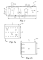
- the side reflectors may be strips of thin reflective film, whether alone or applied to a somewhat stiffer substrate for mechanical support. In such cases it is relatively easy to produce a cavity area that is other than rectangularly-shaped, simply by bending one or more side-reflector strips into a desired shape. This is shown in FIG.
- reference numeral 60 identifies a backlight output area of conventional rectangular design.
- An irregularly shaped side reflector 62 formed for example by bending a strip of reflective material and placing it between the (rectangular- or otherwise-shaped) front and back reflectors, produces an output area with an irregular right edge.
- Other edges of the output area may be similarly shaped to provide a wide variety of non-rectangular output area shapes, e.g., oval.
- R b hemi (effective) a back reflector effective reflectivity for visible unpolarized light
- lossy elements such as LED dies, lenses, packaging, circuitry and exposed circuit board, are included in an area-fraction sense, with the surrounding high-reflectivity materials, to determine R b hemi (effective).
- physical gaps between reflective surfaces are also included in defining this effective reflectivity. The physical location of this R b hemi (effective) surface can then be conveniently drawn as coincident with the mean surface of the physical cavity interior.
- R f hemi is a measurable quantity, describing the hemispherical reflectivity of the front reflector.
- This front reflector can be configured to consist of a single reflective film, or numerous combinations of reflective films or reflective elements. They may be laminated or spaced apart, but in general they are defined as components that are co-extensive with the output face of the cavity and operate together as a system to recycle light from the sources in order to thoroughly mix the light within the cavity.
- the components of the front reflector can include diffusive elements such as diffuser plates, and surface structure diffusers, as well as refractive elements such as lenticular and/or prismatic films.
- T useable (0 deg) is defined as the ratio of the transmitted intensity at 0 degrees (normal to the front reflector plane) with the front reflector and an absorbing polarizer overlaying an all-angle light source (e.g. an angle-mixed recycling cavity), to the intensity at 0 degrees for just the absorbing polarizer overlaying the all-angle light source.
- the characteristic optical property of the front reflector can be more generally specified by T pol ( ⁇ ), where ⁇ represents the solid angle of application acceptance of light from the output area of the backlight, and “pol” refers to the polarization state of that light, which is required for application utility.
- the front reflector as a surface with properties R f hemi , residing at the inner-most surface of the front reflector film, or the inner-most reflective component of the front reflector component stack, and T pol ( ⁇ ), residing at the outer-most surface of the front reflector film, or the outer-most reflective component of the front reflector component stack
- the backlight cavity depth H can then be defined by the perpendicular distance from the R b hemi (effective) surface, and the front reflector innermost surface with property R f hemi .
- an effective cavity depth H eff can be defined using appropriate geometrical constructs.
- T useable (0 deg) may be needed to achieve high LCD-usable brightness, across an application viewer-cone that is distributed about the normal direction.
- T useable (0 deg)
- a suitable designed optical cavity in which a large proportion of the light emitted by internal light sources undergo multiple reflections between substantially coextensive front and back reflectors, will have light rays within the cavity that can become substantially randomized in both direction, and spatial location within the cavity.
- the number of multiple reflections required to achieve this spatial and angular randomization of the light rays will depend to a large extent on the specular and diffusive characteristics for the reflective elements.
- the reader is referred to U.S. Patent Publication 2010/0238686 for a more complete discussion of this topic.
- the brightness through the output surface into any particular output angle ⁇ will be substantially equal at various points along the output surface.
- the “Light Source Lumens” is that which is emitted into the cavity by the light sources disposed within, or optically coupled to the cavity.
- T pol ( ⁇ )/(1 ⁇ R f hemi ⁇ R b hemi (effective)) represents the fractional increase in intensity into a solid angle ⁇ , of polarization “pol”, for the recycling cavity with front and back reflectors, compared with an angle-mixed flux into the forwards hemisphere (relative to the output surface) of the light sources alone.
- LED light-source attributes and light injection geometries in combination with novel high reflection materials, with appropriate front reflector transmission characteristics, can be configured to enable substantially hollow backlights in novel regions of backlight parameter space.
- R b hemi we have measured R b hemi for several materials that have current and potential uses as back reflector components.
- the measurement apparatus employed was custom-built by the applicants, but is straightforward in design and operation.
- a stabilized light source illuminates the sphere through one port.
- a Minolta PR650 spectrophotometer is used to measure the sphere internal wall radiance through a second port. The sample is placed on the third port.
- Calibration of the integrating sphere wall radiance is done by using a known reflectance standard placed on the third port, with sphere-wall radiance is measured with and without the calibration standard.
- Measurement of R hemi is made by placing samples on port 3; sample hemispheric reflectance R hemi is obtained by taking the ratio of the sphere wall radiance with and without sample, and employing a simple integrating sphere brightness-gain algorithm.
- This measurement of R hemi is germane to recycling backlight cavity performance in that it is the all-angle input, all-angle output reflection, measured in a way much like that which occurs in an actual recycling cavity.
- transmittance into a chosen solid angle T( ⁇ ), where ⁇ is defined by the collection aperture and its location relative to the normal to the sample surface is collected using the Minolta PR650 spectrophotometer at the third port.
- the LCD-usable transmittance at normal angle T useable (0 deg), is obtained by using the spectrophotometer at normal angle to the sample, and referencing the sample and overlaying absorbing polarizer (LCD display polarizer SR5518, from San Ritz), to the absorbing polarizer alone.
- R b hemi (effective) value for a recycling cavity that operationally will determine how efficient the cavity is in randomizing ray angles, and creating a spatially uniform output-surface brightness.
- the R b hemi (effective) value will include low reflectivity elements within the recycling cavity, associated with light sources and electronics.
- FIG. 8 depicts a top view of an individual such cluster, with dimensions given in millimeters. Careful inspection of the geometrical arrangement of the 66 RGB die clusters, and the neighboring high reflectivity 2 ⁇ TIPS material, indicated that the exposed area of material associated with the LED packaging and circuitry, was ⁇ 11.2% of the back reflector area, with the remaining 88.8% of the area covered by 2 ⁇ TIPS.
- This value for the recycling backlight's R b hemi (effective) can be validated by using the measured values shown in Table II, for the front reflectors described in Examples C6, C7, C8, 27, and 28 (these designations are used in U.S. Pat. No. 8,469,575) referenced elsewhere, where a complete description of the examples can be found), and applying these measured values of T useable (0 deg) and R f hemi to the equation for LP) above.
- the LED RGB cluster luminous output was assumed to be 3.55 lumens/cluster.
- FIG. 9 also demonstrates the great and surprising impact that small changes in cavity efficiency (represented by the value of R b hemi (effective)) can have on backlight brightness.
- acceptable spatial uniformity refers to both acceptable uniformity of both overall intensity and color. What is considered acceptable brightness and spatial uniformity depends upon the particular application for which the backlight will be used. For example, a common reference standard for LCD uniformity is TCO 05 (The Swedish Confederation of Professional Employees, version 2.0, 2005-09-21, p. 9), which specifies an acceptance threshold luminance ratio of greater than 66%. In the early commercialization of a particular technology, uniformity standards may be lower; for example, when notebook computers were first introduced, acceptable uniformity was in the range of 50-60%. Further, for example, internally illuminated channel letters are another application where luminance uniformity is an important performance metric.
- VESA 9pt Color Nonuniformity Standard Sampled Uniformity and Color of White
- L min is the minimum value of the luminance of the 9 points and L max is the maximum value of the luminance of the 9 points.
- L max is the maximum value of the luminance of the 9 points.
- the VESA 9pt Color Nonuniformity is determined as the largest value of the color difference between any two pairs of the 9 sample points.
- the Color Nonuniformity determined in this manner is equal to the diameter of the smallest circle that would enclose the colors of all of the sampled points when plotted on a Cartesian graph of v′ vs. u′. Lower values of VESA 9pt Color Nonuniformity indicate systems that are more uniform.
- the examples provide numerous illustrations of hollow light-recycling cavities that reside in the desired cavity design space discussed above, and providing at least adequate brightness and uniformity characteristics. Further, the examples demonstrate the effect of different combinations of reflective films for the front and back reflectors. Different light source arrangements are also included, with some being edge- and others direct-lit type. Large-area edge-lit backlights (ranging at least from 12 to 40 inch diagonal measure) are also included. Some of the examples demonstrate the effect of turning off selected light sources, showing in some cases the robustness of the design to light source failure or burnout. Finally, the examples in various combinations are submitted to demonstrate the properties called out in the claims below.
- the backlight system from Examples 20 and 21 was used for these examples with the only difference being that one of the green LEDs was turned off.
- the green LED that was off was located at the left side of the left bank of LEDs when the box was viewed from the output side with the LED bar located along the top.
- the output region of the Edge-Lit, Hollow Backlight was covered by a reflective polarizer (APF mounted on an acrylic plate) which was placed over the output area of the backlight. All of the LEDs (red, green, and blue, except for the single green LED mentioned above, for a total of 4R 7G 4B) were turned on to produce white light. The backlight was bright close to the LEDs and visibly darker at the far end (away from the LEDs).
- Example 21a the same configuration as for Example 21a was used, but only the green LEDs were powered (except for the single green LED mentioned above, for a total of 7G). The backlight appeared much brighter close to the LEDs and darker at the far end (away from the LEDs).
- Example 21a the same configuration as for Example 21a was used, but only the four green LEDs of the right bank of LEDs were powered (for a total of 4G).
- the backlight appeared much brighter on the right side close to the LEDs and was darker at the far end (away from the LEDs) and also darker on the left side where the LEDs did't lit.
- Example 21a the same configuration as for Example 21a was used, but only the three green LEDs of the left bank of LEDs were powered (for a total of 3G).
- the backlight appeared much brighter on the left side close to the LEDs and was darker at the far end (away from the LEDs) and also darker on the right side where the LEDs did't lit.
- the output region of the Edge-Lit, Hollow Backlight was covered by a partial reflector (ARF-89 mounted on an acrylic plate) which was placed over the output area of the backlight.
- the partial reflector had a pass-axis transmission of approximately 11% for visible light.
- the back of the backlight was covered with Bead-coated ESR. All of the LEDs were turned on (red, green, and blue, except for the single green LED mentioned above, for a total of 4R 7G 4B) to produce white light. The backlight appeared uniformly illuminated.
- Example 21e the same configuration as for Example 21e was used, except only the green LEDs were powered (except for the single green LED mentioned above, for a total of 7G). The backlight appeared uniformly illuminated.
- Example 21e the same configuration as for Example 21e was used, except that only the four green LEDs of the right bank of LEDs were powered (for a total of 4G). The backlight appeared uniformly illuminated.
- Example 21e the same configuration as for Example 21e was used, except that only the three green LEDs of the left bank of LEDs were powered. The backlight appeared uniformly illuminated.
- edge-lit examples are plotted in FIG. 10
- direct-lit examples are plotted in FIG. 11 .
- the labels used in the figures correspond to the Example numbering convention above.
- references to “backlights” are also intended to apply to other extended area lighting devices that provide nominally uniform illumination in their intended application. Such other devices may provide either polarized or unpolarized outputs. Examples include light boxes, signs, channel letters, and general illumination devices designed for indoor (e.g. home or office) or outdoor use, sometimes referred to as “luminaires”.
- edge-lit devices can be configured to emit light out of both opposed major surfaces—i.e., both out of the “front reflector” and “back reflector” referred to above—in which case both the front and back reflectors are partially transmissive.
- Such a device can illuminate two independent LCD panels or other graphic members placed on opposite sides of the backlight. In that case the front and back reflectors may be of the same or similar construction.
- LED refers to a diode that emits light, whether visible, ultraviolet, or infrared. It includes incoherent encased or encapsulated semiconductor devices marketed as “LEDs”, whether of the conventional or super radiant variety. If the LED emits non-visible light such as ultraviolet light, and in some cases where it emits visible light, it is packaged to include a phosphor (or it may illuminate a remotely disposed phosphor) to convert short wavelength light to longer wavelength visible light, in some cases yielding a device that emits white light.
- An “LED die” is an LED in its most basic form, i.e., in the form of an individual component or chip made by semiconductor processing procedures. The component or chip can include electrical contacts suitable for application of power to energize the device.
- An LED may also include a cup-shaped reflector or other reflective substrate, encapsulating material formed into a simple dome-shaped lens or any other known shape or structure, extractor(s), and other packaging elements, which elements may be used to produce a forward-emitting, side-emitting, or other desired light output distribution.
- references to LEDs are also intended to apply to other sources capable of emitting bright light, whether colored or white, and whether polarized or unpolarized, in a small emitting area. Examples include semiconductor laser devices, and sources that utilize solid state laser pumping.
Landscapes
- Physics & Mathematics (AREA)
- General Physics & Mathematics (AREA)
- Optics & Photonics (AREA)
- Nonlinear Science (AREA)
- Mathematical Physics (AREA)
- Chemical & Material Sciences (AREA)
- Crystallography & Structural Chemistry (AREA)
- Engineering & Computer Science (AREA)
- General Engineering & Computer Science (AREA)
- Planar Illumination Modules (AREA)
- Non-Portable Lighting Devices Or Systems Thereof (AREA)
Abstract
Description
-
- a recycling optical cavity in which a large proportion of the light undergoes multiple reflections between substantially coextensive front and back reflectors before emerging from the front reflector, which is partially transmissive and partially reflective;
- overall losses for light propagating in the recycling cavity are kept extraordinarily low, for example, both by providing a substantially enclosed cavity of low absorptive loss, including low loss front and back reflectors as well as side reflectors, and by keeping losses associated with the light sources very low, for example, by ensuring the cumulative emitting area of all the light sources is a small fraction of the backlight output area;
- a recycling optical cavity that is hollow, i.e., the lateral transport of light within the cavity occurs predominantly in air, vacuum, or the like rather than in an optically dense medium such as acrylic or glass;
- in the case of a backlight designed to emit only light in a particular (useable) polarization state, the front reflector has a high enough reflectivity for such useable light to support lateral transport or spreading, and for light ray angle randomization to achieve acceptable spatial uniformity of the backlight output, but a high enough transmission into the appropriate application-useable angles to ensure application brightness of the backlight is acceptable;
- the recycling optical cavity contains a component or components that provide the cavity with a balance of specular and diffuse characteristics, the component having sufficient specularity to support significant lateral light transport or mixing within the cavity, but also having sufficient diffusivity to substantially homogenize the angular distribution of steady state light within the cavity, even when injecting light into the cavity only over a narrow range of angles (and further, in the case of a backlight designed to emit only light in a particular (useable) polarization state, recycling within the cavity preferably includes a degree of randomization of reflected light polarization relative to the incident light polarization state, which allows a mechanism by which non-useable polarized light is converted into useable polarized light);
- the front reflector of the recycling cavity has a reflectivity that generally increases with angle of incidence, and a transmission that generally decreases with angle of incidence, where the reflectivity and transmission are for unpolarized visible light and for any plane of incidence, and/or for light of a useable polarization state incident in a plane for which oblique light of the useable polarization state is p-polarized (and further, the front reflector has a high value of hemispheric reflectivity and while also having a sufficiently high transmission of application-useable light);
- light injection optics that partially collimates or confines light initially injected into the recycling cavity to propagation directions close to a transverse plane (the transverse plane being parallel to the output area of the backlight), e.g., an injection beam having an average flux deviation angle from the transverse plane in a range from 0 to 40 degrees, or 0 to 30 degrees, or 0 to 15 degrees.
65 clusters×3 dies/cluster×1 mm2/die=325 mm2.
16 bulbs×(π×4 mm)×820 mm=164,871 mm2.
SEP=((L/6)+(W/3))/2.
For a 6×6 inch output area (L=W=6 inches or 153 mm), the SEP for this example becomes SEP=38 mm. Note that the result remains the same if the spacing between rows is not uniform, or if the spacing between columns is not uniform, as long as the light sources are arranged in three rows and three columns. Note also that each
SEP=((L/1)+(W/18))/2.
For a 6×6 inch output area (L=W=6 inches or 153 mm), the SEP for this example becomes SEP=81 mm. Note that the result remains the same if the spacing of the sources along the y-direction is not uniform. The SEP value of 81 mm is more than twice that of the
SEP=((L/6)+0)/2=L/12.
This corresponds to half the average bulb-to-bulb spacing. For a 6×6 inch output area (L=W=6 inches or 153 mm), the SEP for this example becomes SEP=13 mm.
Parameter A=Aemit/Aout; and
Parameter B=SEP/H
where Aemit, Aout, SEP, and H are as described above.
| REFLECTOR | ||
| TYPE | CONSTRUCTION | POLARIZATION |
| Multilayer | ¼ wave birefringent films, | polarizing |
| asymmetric orientation | ||
| ¼ wave birefringent films, | non-polarizing | |
| symmetric orientation | ||
| pile of plates birefringent | polarizing | |
| films, asymmetric orientation | ||
| pile of plates films, isotropic | non-polarizing | |
| perforated mirrors | non-polarizing | |
| Metal | thin film enhanced metal films | non-polarizing |
| thin film enhanced metal films, | non-polarizing | |
| perforated | ||
| wire grid | polarizing | |
| Diffusive | inorganic filled | non-polarizing |
| voided | non-polarizing | |
| polymer blends | polarizing | |
| birefringent fibers - | polarizing | |
| concentric | ||
| Islands-in-sea birefringent | polarizing | |
| fibers | ||
| Microstructured | Lenticular structures or linear | non-polarizing |
| prisms | ||
| 2D structured surfaces (cube | non-polarizing | |
| corner, lenslet arrays, etc.) | ||
| Cholesteric | lefthand | polarizing |
| (with retarder | ||
| films) | ||
| righthand | polarizing | |
| combinations of both | polarizing - | |
| adjustable | ||
L(Ω)=(Light Source Lumens)/(2π×A out)*T pol(Ω)/(1−R f hemi ×R b hemi(effective))
The “Light Source Lumens” is that which is emitted into the cavity by the light sources disposed within, or optically coupled to the cavity. The expression Tpol(Ω)/(1−Rf hemi×Rb hemi(effective)) represents the fractional increase in intensity into a solid angle Ω, of polarization “pol”, for the recycling cavity with front and back reflectors, compared with an angle-mixed flux into the forwards hemisphere (relative to the output surface) of the light sources alone.
| TABLE I | |||||
| Reflection | |||||
| Ref letter | Material | characteristic | Rb hemi | ||
| A | 3M Vikuiti ESR | Specular | 99.4% | ||
| B | MC-PET | Near-Lambertian | 98.4% | ||
| diffuse | |||||
| C | 3M 2xTiPS | Near-Lambertian | 97.5% | ||
| diffuse | |||||
| D | 3M BGD ESR | Semi-specular | 98.0% | ||
| TABLE II | ||||
| Reflection | Tuseable | |||
| Ref # | Material | characteristic | Rb hemi | (0 deg) |
| 1 | Astra DR55 (DP) | Lambertian | 43.9% | 55.6% |
| 2 | DP + DBEF-Q | Lambertian | 62.8% | 63.1% |
| 3 | DP + ARF-37 | Lambertian | 73.2% | 50.0% |
| 4 | DP + 3xARF | Lambertian | 78.3% | 44.9% |
| DP + GD + BEF + | Lambertian | 75.0% | 59.0% | |
| DBEF | ||||
| 5 | ARF-89 | Specular | 92.5% | 11.0% |
| 36 | ARF-86 + BGD (afs) | Specular | 92.1% | 12.8% |
| 47 | ARF-84 | Specular | 88.5% | 16.3% |
| 58 | ARF-84 + BGD (afs) | Specular | 88.5% | 19.8% |
| 69 | ARF-68 | Specular | 83.2% | 31.6% |
| 7 | ARF-37 | Specular | 67.6% | 61.9% |
| 8 | 3xARF | Specular | 75.4% | 52.0% |
| 9 | 4xARF | Specular | 79.2% | 44.4% |
| 10 | 5xARF | Specular | 81.1% | 39.6% |
| 11 | 5xARF + BGD (ts) | Semi-Specular | 82.1 | 38.3% |
| 12 | APF | Specular | 51.0 | 90.1% |
| 13 | DBEF-D | Semi-Specular | 47.6 | 89.6% |
Δu′v′=√{square root over ((u 1 ′−u 2′)2+(v 1 ′−v 2′)2)}{square root over ((u 1 ′−u 2′)2+(v 1 ′−v 2′)2)}
| Y_Uniformity | |||||
| Example | Y_avg | Y_std | [VESA9] | ||
| 21a | 3206 | 26.8% | 52.8% | ||
| 21b | 1953 | 26.3% | 52.8% | ||
| 21c | 1107 | 32.3% | 39.7% | ||
| 21d | 853 | 33.5% | 40.4% | ||
| 21e | 2788 | 7.8% | 91.0% | ||
| 21f | 1748 | 8.2% | 86.6% | ||
| 21g | 998 | 9.1% | 78.7% | ||
| 21h | 768 | 9.2% | 80.6% | ||
Claims (17)
Priority Applications (1)
| Application Number | Priority Date | Filing Date | Title |
|---|---|---|---|
| US13/938,016 US8926159B2 (en) | 2007-05-20 | 2013-07-09 | Thin hollow backlights with beneficial design characteristics |
Applications Claiming Priority (4)
| Application Number | Priority Date | Filing Date | Title |
|---|---|---|---|
| US93908407P | 2007-05-20 | 2007-05-20 | |
| PCT/US2008/064096 WO2008144636A2 (en) | 2007-05-20 | 2008-05-19 | Design parameters for thin hollow cavity backlights of the light-recycling type |
| US60086209A | 2009-11-19 | 2009-11-19 | |
| US13/938,016 US8926159B2 (en) | 2007-05-20 | 2013-07-09 | Thin hollow backlights with beneficial design characteristics |
Related Parent Applications (3)
| Application Number | Title | Priority Date | Filing Date |
|---|---|---|---|
| PCT/US2008/064096 Continuation WO2008144636A2 (en) | 2007-05-20 | 2008-05-19 | Design parameters for thin hollow cavity backlights of the light-recycling type |
| US12/600,862 Continuation US8523419B2 (en) | 2007-05-20 | 2008-05-19 | Thin hollow backlights with beneficial design characteristics |
| US60086209A Continuation | 2007-05-20 | 2009-11-19 |
Publications (2)
| Publication Number | Publication Date |
|---|---|
| US20140009963A1 US20140009963A1 (en) | 2014-01-09 |
| US8926159B2 true US8926159B2 (en) | 2015-01-06 |
Family
ID=39618836
Family Applications (2)
| Application Number | Title | Priority Date | Filing Date |
|---|---|---|---|
| US12/600,862 Expired - Fee Related US8523419B2 (en) | 2007-05-20 | 2008-05-19 | Thin hollow backlights with beneficial design characteristics |
| US13/938,016 Expired - Fee Related US8926159B2 (en) | 2007-05-20 | 2013-07-09 | Thin hollow backlights with beneficial design characteristics |
Family Applications Before (1)
| Application Number | Title | Priority Date | Filing Date |
|---|---|---|---|
| US12/600,862 Expired - Fee Related US8523419B2 (en) | 2007-05-20 | 2008-05-19 | Thin hollow backlights with beneficial design characteristics |
Country Status (7)
| Country | Link |
|---|---|
| US (2) | US8523419B2 (en) |
| EP (2) | EP2487535A1 (en) |
| JP (1) | JP5584117B2 (en) |
| KR (1) | KR101488042B1 (en) |
| CN (1) | CN101681057B (en) |
| TW (1) | TWI458918B (en) |
| WO (1) | WO2008144636A2 (en) |
Cited By (1)
| Publication number | Priority date | Publication date | Assignee | Title |
|---|---|---|---|---|
| US20160370653A1 (en) * | 2011-10-20 | 2016-12-22 | 3M Innovative Properties Company | Illumination systems with sloped transmission spectrum front reflector |
Families Citing this family (73)
| Publication number | Priority date | Publication date | Assignee | Title |
|---|---|---|---|---|
| EP2069838A2 (en) | 2006-10-06 | 2009-06-17 | Qualcomm Mems Technologies, Inc. | Illumination device with built-in light coupler |
| KR20090094241A (en) * | 2006-10-06 | 2009-09-04 | 퀄컴 엠이엠스 테크놀로지스, 인크. | Thin light bar and method of manufacturing |
| US8107155B2 (en) | 2006-10-06 | 2012-01-31 | Qualcomm Mems Technologies, Inc. | System and method for reducing visual artifacts in displays |
| WO2008144650A1 (en) * | 2007-05-20 | 2008-11-27 | 3M Innovative Properties Company | Collimating light injectors for edge-lit backlights |
| JP5336475B2 (en) | 2007-05-20 | 2013-11-06 | スリーエム イノベイティブ プロパティズ カンパニー | Optical recycling hollow cavity type display backlight |
| CN101681597A (en) * | 2007-05-20 | 2010-03-24 | 3M创新有限公司 | Effectively utilize the white light backlight of colored led light source etc. |
| WO2008144644A2 (en) | 2007-05-20 | 2008-11-27 | 3M Innovative Properties Company | Semi-specular components in hollow cavity light recycling backlights |
| US8434909B2 (en) | 2007-10-09 | 2013-05-07 | Flex Lighting Ii, Llc | Light emitting display with light mixing within a film |
| JP5535923B2 (en) * | 2007-10-09 | 2014-07-02 | ニコール,アンソニー,ジェイ | Optical coupling to illuminated film |
| US8848132B2 (en) | 2008-02-07 | 2014-09-30 | 3M Innovative Properties Company | Hollow backlight with structured films |
| JP5792464B2 (en) * | 2008-02-22 | 2015-10-14 | スリーエム イノベイティブ プロパティズ カンパニー | BACKLIGHT HAVING SELECTIVE OUTPUT LIGHT DISTRIBUTION, DISPLAY SYSTEM USING SAME, AND METHOD FOR FORMING BACKLIGHT |
| US8118468B2 (en) | 2008-05-16 | 2012-02-21 | Qualcomm Mems Technologies, Inc. | Illumination apparatus and methods |
| WO2009149010A1 (en) * | 2008-06-04 | 2009-12-10 | 3M Innovative Properties Company | Hollow backlight with tilted light source |
| EP2313800A4 (en) | 2008-07-10 | 2014-03-19 | 3M Innovative Properties Co | Viscoelastic lightguide |
| CN102171593A (en) | 2008-08-08 | 2011-08-31 | 3M创新有限公司 | Lightguide having a viscoelastic layer for managing light |
| KR20100020214A (en) * | 2008-08-12 | 2010-02-22 | 삼성전자주식회사 | Method of driving a light source, light source apparatus for performing the method and lquid crystal display device having the light source appratus |
| KR20110080170A (en) | 2008-10-27 | 2011-07-12 | 쓰리엠 이노베이티브 프로퍼티즈 컴파니 | Semispecular hollow backlight with gradient extraction |
| KR101696492B1 (en) * | 2008-11-19 | 2017-01-13 | 쓰리엠 이노베이티브 프로퍼티즈 컴파니 | Multilayer Optical Film With Output Confinement in Both Polar and Azimuthal Directions and Related Constructions |
| WO2010059579A1 (en) * | 2008-11-19 | 2010-05-27 | 3M Innovative Properties Company | High transmission flux leveling multilayer optical film and related constructions |
| EP2366077B1 (en) * | 2008-11-19 | 2018-08-15 | 3M Innovative Properties Company | Brewster angle film for light management in luminaires and other lighting systems |
| WO2010059568A1 (en) | 2008-11-19 | 2010-05-27 | 3M Innovative Properties Company | Reflective film combinations with output confinement in both polar and azimuthal directions and related constructions |
| GB2466846A (en) * | 2009-01-13 | 2010-07-14 | Barco Nv | Sensor system and method for detecting a property of light emitted from at least one display area of a display device |
| US8905610B2 (en) | 2009-01-26 | 2014-12-09 | Flex Lighting Ii, Llc | Light emitting device comprising a lightguide film |
| AU2010206525C1 (en) | 2009-01-26 | 2013-11-28 | Flex Lighting Ii, Llc | Illumination via flexible thin films |
| WO2010090924A2 (en) | 2009-02-06 | 2010-08-12 | 3M Innovative Properties Company | Light control film and multi-layer optical film stack |
| KR20120024648A (en) | 2009-04-30 | 2012-03-14 | 쓰리엠 이노베이티브 프로퍼티즈 컴파니 | Task light with glare control member |
| US8917962B1 (en) | 2009-06-24 | 2014-12-23 | Flex Lighting Ii, Llc | Method of manufacturing a light input coupler and lightguide |
| US8684556B2 (en) * | 2009-09-30 | 2014-04-01 | Cree, Inc. | Light emitting diode (LED) lighting systems including low absorption, controlled reflectance and diffusion layers |
| CN102576100B (en) | 2009-10-24 | 2016-05-04 | 3M创新有限公司 | Gradient low index article and method |
| WO2011050236A2 (en) | 2009-10-24 | 2011-04-28 | 3M Innovative Properties Company | Voided diffuser |
| EP2491445B1 (en) | 2009-10-24 | 2018-01-03 | 3M Innovative Properties Company | Light source and display system incorporating same |
| EP2491442A1 (en) | 2009-10-24 | 2012-08-29 | 3M Innovative Properties Company | Immersed reflective polarizer with angular confinement in selected planes of incidence |
| CN102576110B (en) | 2009-10-24 | 2016-02-24 | 3M创新有限公司 | There is the immersed reflective polarizer of high off axis reflector rate |
| EP3258167A3 (en) | 2009-12-08 | 2018-04-18 | 3M Innovative Properties Co. | Optical constructions incorporating a light guide and low refractive index films |
| US9581739B2 (en) | 2009-12-21 | 2017-02-28 | 3M Innovative Properties Company | Transflective articles and light assemblies |
| KR20170109697A (en) * | 2010-02-24 | 2017-09-29 | 도레이 카부시키가이샤 | White reflective film for edge-lit backlight and backlight using the aforementioned |
| EP2558522B1 (en) | 2010-04-14 | 2018-08-01 | 3M Innovative Properties Company | Patterned gradient polymer film |
| CN103038567A (en) | 2010-04-16 | 2013-04-10 | 弗莱克斯照明第二有限责任公司 | Illumination device comprising a film-based lightguide |
| US9028123B2 (en) | 2010-04-16 | 2015-05-12 | Flex Lighting Ii, Llc | Display illumination device with a film-based lightguide having stacked incident surfaces |
| CN102933367B (en) | 2010-05-07 | 2016-06-01 | 3M创新有限公司 | For preparing the equipment of multilayer polymer film |
| JP2013526730A (en) | 2010-05-21 | 2013-06-24 | スリーエム イノベイティブ プロパティズ カンパニー | Color-reducing partially reflective multilayer optical film |
| EP2580619B1 (en) | 2010-06-10 | 2019-07-24 | 3M Innovative Properties Company | Display device and method of lc panel protection |
| US9103956B2 (en) | 2010-07-28 | 2015-08-11 | Flex Lighting Ii, Llc | Light emitting device with optical redundancy |
| CA2829388C (en) | 2011-03-09 | 2018-09-25 | Flex Lighting Ii, Llc | Light emitting device with adjustable light output profile |
| US8705915B2 (en) | 2011-03-15 | 2014-04-22 | Qualcomm Mems Technologies, Inc. | Light turning feature patterns for lightguides |
| WO2012138554A2 (en) | 2011-04-07 | 2012-10-11 | 3M Innovative Properties Company | Decorative light |
| KR101971754B1 (en) | 2011-10-20 | 2019-04-23 | 쓰리엠 이노베이티브 프로퍼티즈 컴파니 | Apodized broadband partial reflectors having differing optical packets |
| US9322967B2 (en) | 2011-10-20 | 2016-04-26 | 3M Innovative Properties Company | Apodized broadband partial reflectors |
| TW201337349A (en) * | 2012-03-12 | 2013-09-16 | Innocom Tech Shenzhen Co Ltd | Optical element and display system |
| CN202629814U (en) * | 2012-05-31 | 2012-12-26 | 京东方科技集团股份有限公司 | Lateral backlight module |
| US9753213B2 (en) * | 2012-07-31 | 2017-09-05 | Mitsubishi Electric Corporation | Planar light source device and liquid crystal display apparatus |
| CN104736927B (en) | 2012-10-30 | 2016-12-14 | 3M创新有限公司 | The light tunnel of bending is extracted |
| WO2014070498A1 (en) | 2012-10-30 | 2014-05-08 | 3M Innovative Properties Company | Rectangular light duct extraction |
| US10838127B2 (en) | 2013-02-20 | 2020-11-17 | 3M Innovative Properties Company | Absorbing, reflecting and collimating polarizer stack and backlights incorporating same |
| JP2014163690A (en) * | 2013-02-21 | 2014-09-08 | Mitsutoyo Corp | Shape measurement device |
| US9690032B1 (en) | 2013-03-12 | 2017-06-27 | Flex Lighting Ii Llc | Lightguide including a film with one or more bends |
| US11009646B2 (en) | 2013-03-12 | 2021-05-18 | Azumo, Inc. | Film-based lightguide with interior light directing edges in a light mixing region |
| US9566751B1 (en) | 2013-03-12 | 2017-02-14 | Flex Lighting Ii, Llc | Methods of forming film-based lightguides |
| JP2014222575A (en) * | 2013-05-13 | 2014-11-27 | キヤノン株式会社 | Light source device |
| US10161593B2 (en) | 2014-02-25 | 2018-12-25 | 3M Innovative Properties Company | Solid state lighting device with virtual filament(s) |
| US9046637B1 (en) | 2014-02-25 | 2015-06-02 | 3M Innovative Properties Company | Tubular lighting systems with inner and outer structured surfaces |
| US10261233B2 (en) | 2014-11-25 | 2019-04-16 | Microsoft Technology Licensing, Llc | Backlight unit with controlled light extraction |
| JP6364335B2 (en) | 2014-12-04 | 2018-07-25 | 株式会社ジャパンディスプレイ | Display device |
| DE102015100977A1 (en) * | 2015-01-23 | 2016-07-28 | Vorwerk & Co. Interholding Gmbh | Device for processing a surface |
| CN110622048B (en) | 2017-03-02 | 2023-03-28 | 3M创新有限公司 | Dynamic reflective color film with low optical thickness sensitivity |
| US10241253B2 (en) * | 2017-05-11 | 2019-03-26 | Glo Ab | Light bar containing symmetric LED placement and method of making thereof |
| US10446112B2 (en) * | 2017-09-20 | 2019-10-15 | Apple Inc. | Electronic devices having light sensors with thin-film filters |
| US11036085B2 (en) | 2018-10-05 | 2021-06-15 | Microsoft Technology Licensing, Llc | Optically-calibrated backlight unit internal supports |
| WO2020142731A1 (en) | 2019-01-03 | 2020-07-09 | Flex Lighting Ii, Llc | Reflective display comprising a lightguide and light turning film creating multiple illumination peaks |
| CN113287061A (en) * | 2019-01-07 | 2021-08-20 | 3M创新有限公司 | Backlight for an image forming apparatus including an optical cavity formed by opposing cold and hot mirrors |
| US11513274B2 (en) | 2019-08-01 | 2022-11-29 | Azumo, Inc. | Lightguide with a light input edge between lateral edges of a folded strip |
| JP7412729B2 (en) | 2019-09-09 | 2024-01-15 | アイリスオーヤマ株式会社 | electric pressure cooker |
| US11800051B2 (en) * | 2021-12-17 | 2023-10-24 | Raytheon Company | Device and method for optical sensor calibration |
Citations (215)
| Publication number | Priority date | Publication date | Assignee | Title |
|---|---|---|---|---|
| US3610729A (en) | 1969-06-18 | 1971-10-05 | Polaroid Corp | Multilayered light polarizer |
| US3711176A (en) | 1971-01-14 | 1973-01-16 | Dow Chemical Co | Highly reflective thermoplastic bodies for infrared, visible or ultraviolet light |
| US3773882A (en) | 1971-10-01 | 1973-11-20 | Dow Chemical Co | Method for multilayer coextrusion |
| US3884606A (en) | 1971-10-01 | 1975-05-20 | Dow Chemical Co | Apparatus for multilayer coextrusion of sheet or film |
| US4040727A (en) | 1975-09-10 | 1977-08-09 | Rockwell International Corporation | Transflector |
| US4446305A (en) | 1981-03-02 | 1984-05-01 | Polaroid Corporation | Optical device including birefringent polymer |
| US4456336A (en) | 1981-10-06 | 1984-06-26 | Minnesota Mining And Manufacturing Company | High brightness internal reflector for liquid crystal displays and its method of fabrication |
| US4540623A (en) | 1983-10-14 | 1985-09-10 | The Dow Chemical Company | Coextruded multi-layered articles |
| US4791540A (en) | 1987-05-26 | 1988-12-13 | Minnesota Mining And Manufacturing Company | Light fixture providing normalized output |
| US5103337A (en) | 1990-07-24 | 1992-04-07 | The Dow Chemical Company | Infrared reflective optical interference film |
| US5126880A (en) | 1990-12-18 | 1992-06-30 | The Dow Chemical Company | Polymeric reflective bodies with multiple layer types |
| US5136479A (en) | 1990-06-19 | 1992-08-04 | E-Systems, Inc. | Device and method for creating an areal light source |
| US5337068A (en) | 1989-12-22 | 1994-08-09 | David Sarnoff Research Center, Inc. | Field-sequential display system utilizing a backlit LCD pixel array and method for forming an image |
| EP0426397B1 (en) | 1989-11-01 | 1994-08-24 | Hewlett-Packard Company | Asymmetrical reflector for LED |
| US5360659A (en) | 1993-05-24 | 1994-11-01 | The Dow Chemical Company | Two component infrared reflecting film |
| US5381309A (en) | 1993-09-30 | 1995-01-10 | Honeywell Inc. | Backlit display with enhanced viewing properties |
| EP0650010A1 (en) | 1993-09-24 | 1995-04-26 | T. CHATANI & COMPANY LTD. | Surface illuminating apparatus |
| WO1995017699A1 (en) | 1993-12-21 | 1995-06-29 | Minnesota Mining And Manufacturing Company | Reflective polarizer display |
| WO1995017303A1 (en) | 1993-12-21 | 1995-06-29 | Minnesota Mining And Manufacturing Company | Multilayered optical film |
| WO1995017691A1 (en) | 1993-12-21 | 1995-06-29 | Minnesota Mining And Manufacturing Company | Optical polarizer |
| WO1995017692A1 (en) | 1993-12-21 | 1995-06-29 | Minnesota Mining And Manufacturing Company | Reflective polarizer with brightness enhancement |
| US5440197A (en) | 1993-10-05 | 1995-08-08 | Tir Technologies, Inc. | Backlighting apparatus for uniformly illuminating a display panel |
| US5448404A (en) | 1992-10-29 | 1995-09-05 | The Dow Chemical Company | Formable reflective multilayer body |
| US5453855A (en) | 1992-12-15 | 1995-09-26 | Koito Manufacturing Co., Ltd. | Liquid crystal display device backlit by LED's coupled to printed circuit board |
| JPH08153405A (en) | 1994-06-21 | 1996-06-11 | Nakaya:Kk | Planar light source |
| WO1996019347A3 (en) | 1994-12-20 | 1996-08-29 | Minnesota Mining & Mfg | Multilayered optical film |
| JPH095737A (en) | 1995-06-19 | 1997-01-10 | Canon Inc | Backlight device and liquid crystal display device provided with the back light device |
| US5594830A (en) | 1992-03-23 | 1997-01-14 | Minnesota Mining And Manufacturing Co. | Luminaire device |
| WO1997001726A1 (en) | 1995-06-26 | 1997-01-16 | Minnesota Mining And Manufacturing Company | Backlight system with multilayer optical film reflector |
| US5751388A (en) | 1995-04-07 | 1998-05-12 | Honeywell Inc. | High efficiency polarized display |
| US5771328A (en) | 1995-03-03 | 1998-06-23 | Minnesota Mining And Manufacturing Company | Light directing film having variable height structured surface and light directing article constructed therefrom |
| JPH10170723A (en) | 1996-12-10 | 1998-06-26 | Nitto Denko Corp | Surface light source unit |
| JPH10213712A (en) | 1997-01-30 | 1998-08-11 | Fujitsu Kasei Kk | Backlight unit |
| US5793456A (en) | 1993-01-11 | 1998-08-11 | U.S. Philips Corporation | Cholesteric polarizer and the manufacture thereof |
| US5816677A (en) | 1905-03-01 | 1998-10-06 | Canon Kabushiki Kaisha | Backlight device for display apparatus |
| US5825543A (en) | 1996-02-29 | 1998-10-20 | Minnesota Mining And Manufacturing Company | Diffusely reflecting polarizing element including a first birefringent phase and a second phase |
| US5828488A (en) | 1993-12-21 | 1998-10-27 | Minnesota Mining And Manufacturing Co. | Reflective polarizer display |
| US5845038A (en) | 1997-01-28 | 1998-12-01 | Minnesota Mining And Manufacturing Company | Optical fiber illumination system |
| US5867316A (en) | 1996-02-29 | 1999-02-02 | Minnesota Mining And Manufacturing Company | Multilayer film having a continuous and disperse phase |
| JPH1139916A (en) | 1997-07-18 | 1999-02-12 | Matsushita Electric Works Ltd | Portable lighting device |
| JPH1172625A (en) | 1997-06-30 | 1999-03-16 | Toshiba Lighting & Technol Corp | Back light and liquid crystal display device using it |
| WO1999039224A1 (en) | 1998-01-28 | 1999-08-05 | Minnesota Mining And Manufacturing Company | Infrared interference filter |
| WO1999036248A3 (en) | 1998-01-13 | 1999-09-23 | Minnesota Mining & Mfg | Process for making multilayer optical films |
| JPH11260133A (en) | 1998-03-15 | 1999-09-24 | Omron Corp | Surface light source device |
| US5971551A (en) | 1995-07-07 | 1999-10-26 | Arch Development Corporation | Nonimaging optical concentrators and illuminators |
| US5976686A (en) | 1997-10-24 | 1999-11-02 | 3M Innovative Properties Company | Diffuse reflective articles |
| WO1999036262A3 (en) | 1998-01-13 | 1999-11-18 | Minnesota Mining & Mfg | Modified copolyesters and improved multilayer reflective films |
| US6019485A (en) | 1993-04-28 | 2000-02-01 | Minnesota Mining & Mfg. Co. | Nonimaging optical illumination system |
| US6036328A (en) | 1995-05-23 | 2000-03-14 | Sharp Kabushiki Kaisha | Plane-shaped lighting device and a display using such a device |
| US6080467A (en) | 1995-06-26 | 2000-06-27 | 3M Innovative Properties Company | High efficiency optical devices |
| WO2000043815A1 (en) | 1999-01-26 | 2000-07-27 | Fusion Lighting, Inc. | Light pipe utilizing plastic sheets |
| US6122103A (en) | 1999-06-22 | 2000-09-19 | Moxtech | Broadband wire grid polarizer for the visible spectrum |
| US6157486A (en) | 1998-01-13 | 2000-12-05 | 3M Innovative Properties Company | Retroreflective dichroic reflector |
| US6157490A (en) | 1998-01-13 | 2000-12-05 | 3M Innovative Properties Company | Optical film with sharpened bandedge |
| US6262842B1 (en) | 1995-06-26 | 2001-07-17 | 3M Innovative Properties Company | Transflective displays with reflective polarizing transflector |
| US6267492B1 (en) | 1999-04-15 | 2001-07-31 | 3M Innovative Properties Company | Illumination device with side emitting light guide |
| US6276803B1 (en) | 1996-05-14 | 2001-08-21 | Omron Corporation | Optical path converting optical element, optical path converter, and optical projector and image display apparatus using said optical element |
| US6280063B1 (en) | 1997-05-09 | 2001-08-28 | 3M Innovative Properties Company | Brightness enhancement article |
| US6282821B1 (en) | 1998-06-25 | 2001-09-04 | 3M Innovative Properties Company | Low-loss face diffuser films for backlit signage and methods for using same |
| US20010030857A1 (en) | 1999-11-30 | 2001-10-18 | Reflexite Corporation | Luminaire system |
| US6354709B1 (en) | 1998-02-18 | 2002-03-12 | 3M Innovative Properties Company | Optical film |
| US6368699B1 (en) | 1995-06-26 | 2002-04-09 | 3M Innovative Properties Company | Multilayer polymer film with additional coatings or layers |
| US6367941B2 (en) | 1999-02-24 | 2002-04-09 | 3M Innovative Properties Company | Illumination device for producing predetermined intensity patterns |
| US20020060907A1 (en) | 2000-04-25 | 2002-05-23 | Honeywell International Inc. | Hollow cavity light guide for the distriubution of collimated light to a liquid crystal display |
| US20020070914A1 (en) | 2000-12-12 | 2002-06-13 | Philips Electronics North America Corporation | Control and drive circuit arrangement for illumination performance enhancement with LED light sources |
| JP2002202738A (en) | 2000-12-28 | 2002-07-19 | Kazuyoshi Nishikawa | Thin self-luminous cavity diffusion display device |
| US6454452B1 (en) | 1999-04-22 | 2002-09-24 | Mitsubishi Denki Kabushiki Kaisha | Backlight for liquid crystal display device |
| US20020159019A1 (en) | 2001-02-22 | 2002-10-31 | Pokorny Richard John | Optical bodies containing cholesteric liquid crystal material and methods of manufacture |
| US20020175632A1 (en) | 2001-05-22 | 2002-11-28 | Yazaki Corporation | Led backlight |
| WO2002097324A1 (en) | 2001-06-01 | 2002-12-05 | Lumileds Lighting U.S., Llc | Compact illumination system and display device |
| US20030043567A1 (en) | 2001-08-27 | 2003-03-06 | Hoelen Christoph Gerard August | Light panel with enlarged viewing window |
| US6531230B1 (en) | 1998-01-13 | 2003-03-11 | 3M Innovative Properties Company | Color shifting film |
| US20030086680A1 (en) | 2001-11-02 | 2003-05-08 | Honeywell International Inc. | Hollow wedge shaped light guide |
| US6566689B2 (en) | 2001-05-08 | 2003-05-20 | Koninklijke Philips Electronics N.V. | Illumination system and display device |
| US6600175B1 (en) | 1996-03-26 | 2003-07-29 | Advanced Technology Materials, Inc. | Solid state white light emitter and display using same |
| EP1333705A2 (en) | 2002-01-31 | 2003-08-06 | Matsushita Electric Industrial Co., Ltd. | High-frequency heating apparatus |
| US6636283B2 (en) | 2000-03-31 | 2003-10-21 | Mitsubishi Denki Kabushiki Kaisha | Front light, reflective liquid crystal display device and personal digital assistant |
| US20030202363A1 (en) | 2000-08-31 | 2003-10-30 | Masaya Adachi | Plane-like lighting units and display equipment provided therewith |
| US6663262B2 (en) | 2001-09-10 | 2003-12-16 | 3M Innovative Properties Company | Backlighting transmissive displays |
| US6673425B1 (en) | 2000-10-27 | 2004-01-06 | 3M Innovative Properties Company | Method and materials for preventing warping in optical films |
| JP2004031180A (en) | 2002-06-27 | 2004-01-29 | Kawaguchiko Seimitsu Co Ltd | Backlight device |
| JP2004055430A (en) | 2002-07-23 | 2004-02-19 | Kawaguchiko Seimitsu Co Ltd | Back light system |
| JP2004071576A (en) | 2003-08-18 | 2004-03-04 | Minnesota Mining & Mfg Co <3M> | Surface light emitting device |
| JP2004087973A (en) | 2002-08-28 | 2004-03-18 | Sharp Corp | Surface-mount side surface-emitting diode and its manufacturing method |
| US20040061814A1 (en) | 2002-09-25 | 2004-04-01 | Lg.Philips Lcd Co., Ltd. | Backlight device for liquid crystal display and method of fabricating the same |
| US20040066651A1 (en) | 2002-07-09 | 2004-04-08 | Yuko Harumoto | Light source system |
| US6738349B1 (en) | 2000-03-01 | 2004-05-18 | Tektronix, Inc. | Non-intrusive measurement of end-to-end network properties |
| JP2004158336A (en) | 2002-11-07 | 2004-06-03 | Advanced Display Inc | Surface light source device and liquid crystal display device using the device |
| JP2004171947A (en) | 2002-11-20 | 2004-06-17 | Harison Toshiba Lighting Corp | Backlight device |
| US20040119908A1 (en) | 2002-12-18 | 2004-06-24 | Advanced Display Inc. | Planar light source device, liquid crystal display apparatus, and display apparatus |
| US6762743B2 (en) | 2001-07-16 | 2004-07-13 | Fujitsu Limited | Display device employing a field-sequential method |
| US6783349B2 (en) | 1998-01-13 | 2004-08-31 | 3M Innovative Properties Company | Apparatus for making multilayer optical films |
| US6788358B1 (en) | 1999-10-08 | 2004-09-07 | Lg. Philips Lcd Co., Ltd. | Light unit in liquid crystal display |
| WO2004031818A3 (en) | 2002-10-02 | 2004-10-07 | 3M Innovative Properties Co | Light source assembly and light-guide light suitable for an illuminated display |
| US20040196667A1 (en) | 2001-10-03 | 2004-10-07 | Lea Michael Charles | Light-guide lights providing a substantially monochromatic beam |
| US6809892B2 (en) | 2000-07-26 | 2004-10-26 | 3M Innovative Properties Company | Hollow surface illuminator |
| US20040219338A1 (en) | 2003-05-01 | 2004-11-04 | Hebrink Timothy J. | Materials, configurations, and methods for reducing warpage in optical films |
| US6814456B1 (en) | 2003-05-15 | 2004-11-09 | Toppoly Optoelectronics Corp. | Back light module |
| JP2004342429A (en) | 2003-05-15 | 2004-12-02 | Advanced Display Inc | Planar light source device, and liquid crystal display equipped with same |
| US20050007756A1 (en) | 2003-07-09 | 2005-01-13 | Chunghwa Picture Tubes, Ltd. | Reflecting apparatus for backlight module of flat panel display |
| US20050007758A1 (en) | 2003-07-11 | 2005-01-13 | Chun-Yu Lee | Light source device with optical guiding member and planar light source device employing same |
| US6846089B2 (en) | 2003-05-16 | 2005-01-25 | 3M Innovative Properties Company | Method for stacking surface structured optical films |
| US20050063195A1 (en) | 2000-07-25 | 2005-03-24 | Fuji Photo Film, Co., Ltd. | Electronic flash, electronic camera and light emitting head |
| JP2005093147A (en) | 2003-09-16 | 2005-04-07 | Sharp Corp | Lighting system and display device equipped with the same, and portable electronic equipment |
| US20050073825A1 (en) | 2003-10-06 | 2005-04-07 | Kuo Chia Shin | Light-inverse type guidelight plate |
| US6893135B2 (en) | 2000-03-16 | 2005-05-17 | 3M Innovative Properties Company | Light guides suitable for illuminated displays |
| US6905212B2 (en) | 2003-07-02 | 2005-06-14 | Hewlett-Packard Development Company, L.P. | Varying light beam for a display system |
| US20050135117A1 (en) | 2003-12-23 | 2005-06-23 | Lamb David J. | Hybrid lightguide backlight |
| US20050135115A1 (en) | 2003-12-23 | 2005-06-23 | Lamb David J. | Multiple lightguide backlight |
| JP2005173546A (en) | 2003-11-18 | 2005-06-30 | Toray Ind Inc | Light reflective film and surface light source using the same |
| DE19961491B4 (en) | 1999-05-25 | 2005-08-04 | Siteco Beleuchtungstechnik Gmbh | Interior light with hollow fiber optic cable |
| US6937303B2 (en) | 2001-12-18 | 2005-08-30 | Samsung Electronics Co., Ltd. | Transmissive and reflective type liquid crystal display |
| US20050200295A1 (en) | 2004-03-11 | 2005-09-15 | Lim Kevin L.L. | System and method for producing white light using LEDs |
| JP2005292546A (en) | 2004-04-01 | 2005-10-20 | Mitsubishi Electric Corp | Liquid crystal display device of low power consumption |
| US20050243576A1 (en) | 2004-05-03 | 2005-11-03 | Samsung Electro-Mechanics Co., Ltd. | Light emitting diode array module for providing backlight and backlight unit having the same |
| JP2005327682A (en) | 2004-05-17 | 2005-11-24 | Sony Corp | Backlight device and liquid crystal display device |
| US20050265042A1 (en) | 2004-05-27 | 2005-12-01 | Samsung Electro-Mechanics Co., Ltd. | Vertical light emitting type backlight module |
| US20050265046A1 (en) | 2004-05-25 | 2005-12-01 | Au Optronics Corp. | Backlight module for a liquid crystal display |
| US20050265029A1 (en) | 2004-06-01 | 2005-12-01 | 3M Innovative Properties Company | Led array systems |
| US6975455B1 (en) | 2000-04-18 | 2005-12-13 | 3M Innovative Properties Company | Transflective layer for displays |
| US6974229B2 (en) | 2003-05-21 | 2005-12-13 | Lumileds Lighting U.S., Llc | Devices for creating brightness profiles |
| US20050280756A1 (en) | 2004-06-21 | 2005-12-22 | Samsung Electronics Co., Ltd. | Blacklight assembly and display device having the same |
| US20050286264A1 (en) | 2004-06-29 | 2005-12-29 | Gi-Cherl Kim | Backlight for display device, light source for display device, and light emitting diode used therefor |
| US20050285133A1 (en) | 2004-06-18 | 2005-12-29 | Chi Mei Optoelectronics Corp. | Light emitting diode package |
| US20060002141A1 (en) | 2004-06-30 | 2006-01-05 | Ouderkirk Andrew J | Phosphor based illumination system having a short pass reflector and method of making same |
| US20060005620A1 (en) | 2002-03-20 | 2006-01-12 | Atsushi Koike | Flow rate measuring method and flowmeter, flow rate measuring section package used for them and flow rate measuring unit using them, and piping leakage inspection device using flowmeter |
| WO2006010249A1 (en) | 2004-07-27 | 2006-02-02 | The University Of British Columbia | Diffuser for light from light source array and displays incorporating same |
| US20060028817A1 (en) | 1995-06-27 | 2006-02-09 | Solid State Opto Limited | Light emitting panel assemblies |
| EP1640756A1 (en) | 2004-09-27 | 2006-03-29 | Barco N.V. | Methods and systems for illuminating |
| US20060082700A1 (en) | 2004-10-15 | 2006-04-20 | Gehlsen Mark D | Composite diffuser plates and direct-lit liquid crystal displays using same |
| WO2006043344A1 (en) | 2004-10-21 | 2006-04-27 | Minebea Co., Ltd. | Surface illuminator |
| US20060103777A1 (en) | 2004-11-15 | 2006-05-18 | 3M Innovative Properties Company | Optical film having a structured surface with rectangular based prisms |
| US7052168B2 (en) | 2003-12-17 | 2006-05-30 | 3M Innovative Properties Company | Illumination device |
| US20060124918A1 (en) | 2004-12-09 | 2006-06-15 | 3M Innovative Properties Company | Polychromatic LED's and related semiconductor devices |
| US20060131601A1 (en) | 2004-12-21 | 2006-06-22 | Ouderkirk Andrew J | Illumination assembly and method of making same |
| US7072096B2 (en) | 2001-12-14 | 2006-07-04 | Digital Optics International, Corporation | Uniform illumination system |
| US20060146562A1 (en) | 2004-12-30 | 2006-07-06 | 3M Innovative Properties Company | Optical film having a surface with rounded structures |
| US20060146566A1 (en) | 2004-12-30 | 2006-07-06 | Byung-Soo Ko | Optical film having a structured surface with concave pyramid-shaped structures |
| US20060152943A1 (en) | 2004-12-30 | 2006-07-13 | Byung-Soo Ko | Optical film having a structured surface with offset prismatic structures |
| US20060187650A1 (en) | 2005-02-24 | 2006-08-24 | 3M Innovative Properties Company | Direct lit backlight with light recycling and source polarizers |
| JP2006221922A (en) | 2005-02-09 | 2006-08-24 | Mitsubishi Rayon Co Ltd | Led planar light source device |
| US20060193577A1 (en) | 2005-02-28 | 2006-08-31 | Ouderkirk Andrew J | Reflective polarizers containing polymer fibers |
| WO2006098400A1 (en) | 2005-03-17 | 2006-09-21 | Tohoku University | Liquid crystal display and backlight unit |
| US20060210726A1 (en) | 2004-06-17 | 2006-09-21 | 3M Innovative Properties Company | Optical film assembly and display device |
| JP2006269364A (en) | 2005-03-25 | 2006-10-05 | Mitsubishi Rayon Co Ltd | Led surface light source device |
| US20060221610A1 (en) | 2005-04-01 | 2006-10-05 | Chew Tong F | Light-emitting apparatus having a plurality of overlapping panels forming recesses from which light is emitted |
| JP2006269365A (en) | 2005-03-25 | 2006-10-05 | Mitsubishi Rayon Co Ltd | Led surface light source device |
| US20060220040A1 (en) | 2005-02-28 | 2006-10-05 | Toshihiro Suzuki | Surface illuminator and liquid crystal display having the same |
| US20060250707A1 (en) | 2005-05-05 | 2006-11-09 | 3M Innovative Properties Company | Optical film having a surface with rounded pyramidal structures |
| US20060257678A1 (en) | 2005-05-10 | 2006-11-16 | Benson Olester Jr | Fiber reinforced optical films |
| US20060262564A1 (en) | 2005-05-17 | 2006-11-23 | Nec Lcd Technologies, Ltd. | Backlight and liquid crystal display device |
| US20060268554A1 (en) | 2005-05-31 | 2006-11-30 | The University Of British Columbia | Perforated multi-layer optical film luminaire |
| US20060284569A1 (en) | 2005-06-16 | 2006-12-21 | Au Optronics Corporation | Balanced circuit for multi-LED driver |
| US20060290844A1 (en) | 2005-06-24 | 2006-12-28 | Epstein Kenneth A | Optical element for lateral light spreading in edge-lit displays and system using same |
| US20060290842A1 (en) | 2005-06-24 | 2006-12-28 | Epstein Kenneth A | Optical element for lateral light spreading in back-lit displays and system using same |
| US20070008722A1 (en) | 2005-07-01 | 2007-01-11 | Sony Corporation | Light source apparatus and display apparatus |
| US7164836B2 (en) | 2001-10-03 | 2007-01-16 | 3M Innovative Properties Company | Light-guide lights suitable for use in illuminated displays |
| US20070024994A1 (en) | 2005-07-29 | 2007-02-01 | 3M Innovative Properties Company | Structured optical film with interspersed pyramidal structures |
| US20070047262A1 (en) | 2005-08-27 | 2007-03-01 | 3M Innovative Properties Company | Edge-lit backlight having light recycling cavity with concave transflector |
| US20070047228A1 (en) | 2005-08-27 | 2007-03-01 | 3M Innovative Properties Company | Methods of forming direct-lit backlights having light recycling cavity with concave transflector |
| US20070047254A1 (en) | 2005-08-27 | 2007-03-01 | 3M Innovative Properties Company | Illumination assembly and system |
| US20070081330A1 (en) | 2005-10-12 | 2007-04-12 | Lg Philips Lcd Co., Ltd. | Light emitting package, backlight unit and liquid crystal display device including the same |
| WO2006125174A3 (en) | 2005-05-19 | 2007-04-12 | 3M Innovative Properties Co | Thin internally illuminated sign |
| US20070091641A1 (en) | 2005-10-20 | 2007-04-26 | Industrial Technology Research Institute | Backlight structure |
| US7220036B2 (en) | 2005-05-20 | 2007-05-22 | 3M Innovative Properties Company | Thin direct-lit backlight for LCD display |
| US7229198B2 (en) | 2003-06-16 | 2007-06-12 | Mitsubishi Denki Kabushiki Kaisha | Planar light source device and display device using the same |
| EP1070913B1 (en) | 1999-07-23 | 2007-06-27 | Siteco Beleuchtungstechnik GmbH | Compact luminaire having a hollow light conductor |
| US20070147037A1 (en) | 2005-12-22 | 2007-06-28 | Dynascan Technology Corp. | Super slim LCD backlight device using uniforming chamber |
| US20070153162A1 (en) | 2005-12-30 | 2007-07-05 | Wright Robin E | Reinforced reflective polarizer films |
| US20070153548A1 (en) | 2004-05-21 | 2007-07-05 | Sharp Kabushiki Kaisha | Backlight unit and liquid crystal display device having the same |
| US20070153384A1 (en) | 2005-12-30 | 2007-07-05 | Ouderkirk Andrew J | Reinforced reflective polarizer films |
| US20070171676A1 (en) | 2006-01-20 | 2007-07-26 | Hon Hai Precision Industry Co., Ltd. | Backlight module |
| US20070189032A1 (en) | 2006-02-10 | 2007-08-16 | Hon Hai Precision Industry Co., Ltd. | Backlight system |
| EP1837701A1 (en) | 2006-03-24 | 2007-09-26 | LG Electronics, Inc. | Surface light source comprising a hollow light guide for a backlight unit and a liquid crystal display using the same |
| US7277609B2 (en) | 2004-11-05 | 2007-10-02 | Optical Research Associates | Methods for manipulating light extraction from a light guide |
| US7285802B2 (en) | 2004-12-21 | 2007-10-23 | 3M Innovative Properties Company | Illumination assembly and method of making same |
| US20070257270A1 (en) | 2006-05-02 | 2007-11-08 | 3M Innovative Properties Company | Led package with wedge-shaped optical element |
| US20070258241A1 (en) | 2006-05-02 | 2007-11-08 | 3M Innovative Properties Company | Led package with non-bonded converging optical element |
| US20070257266A1 (en) | 2006-05-02 | 2007-11-08 | 3M Innovative Properties Company Will Follow | Led package with converging optical element |
| US20070258246A1 (en) | 2006-05-02 | 2007-11-08 | 3M Innovative Properties Company | Led package with compound converging optical element |
| US7296916B2 (en) | 2004-12-21 | 2007-11-20 | 3M Innovative Properties Company | Illumination assembly and method of making same |
| US20080002256A1 (en) | 2006-06-30 | 2008-01-03 | 3M Innovative Properties Company | Optical article including a beaded layer |
| US7317182B2 (en) | 2006-05-24 | 2008-01-08 | 3M Innovative Properties Company | Backlight wedge with encapsulated light source |
| US20080025045A1 (en) | 2006-07-25 | 2008-01-31 | Jenn-Wei Mii | Brightness Enhancement Structure of Side-Type LCD Backlight Module |
| US7329982B2 (en) | 2004-10-29 | 2008-02-12 | 3M Innovative Properties Company | LED package with non-bonded optical element |
| US20080049419A1 (en) | 2006-08-25 | 2008-02-28 | 3M Innovative Properties Company | Backlight suitable for display devices |
| US20080057277A1 (en) | 2006-08-30 | 2008-03-06 | 3M Innovative Properties Company | Polymer fiber polarizers |
| JP2008060061A (en) | 2006-08-03 | 2008-03-13 | Harison Toshiba Lighting Corp | Hollow type flat lighting system |
| WO2006127367A3 (en) | 2005-05-20 | 2008-04-03 | Gen Electric | Light diffusing films, methods of making the same, and articles using the same |
| US7364342B2 (en) | 1999-02-23 | 2008-04-29 | Solid State Opto Limited | Light redirecting films pattern of variable optical elements |
| JP2003532133A5 (en) | 2001-04-24 | 2008-06-19 | ||
| EP1942302A1 (en) | 2005-10-28 | 2008-07-09 | Takiron Co., Ltd. | Surface-emitting device and light-emitting method for surface-emitting device |
| US7436996B2 (en) | 2001-06-07 | 2008-10-14 | Genoa Color Technologies Ltd | Device, system and method of data conversion for wide gamut displays |
| US7446827B2 (en) | 2004-10-15 | 2008-11-04 | 3M Innovative Properties Company | Direct-lit liquid crystal displays with laminated diffuser plates |
| WO2008144656A2 (en) | 2007-05-20 | 2008-11-27 | 3M Innovative Properties Company | Light recycling hollow cavity type display backlight |
| WO2008144644A2 (en) | 2007-05-20 | 2008-11-27 | 3M Innovative Properties Company | Semi-specular components in hollow cavity light recycling backlights |
| WO2008144650A1 (en) | 2007-05-20 | 2008-11-27 | 3M Innovative Properties Company | Collimating light injectors for edge-lit backlights |
| US7481563B2 (en) | 2006-09-21 | 2009-01-27 | 3M Innovative Properties Company | LED backlight |
| WO2008147753A3 (en) | 2007-05-20 | 2009-02-05 | 3M Innovative Properties Co | White light backlights and the like with efficient utilization of colored led sources |
| WO2008146229A3 (en) | 2007-05-29 | 2009-02-12 | Koninkl Philips Electronics Nv | Illumination system, luminaire and backlighting unit |
| US7513634B2 (en) | 2007-05-21 | 2009-04-07 | National Tsing Hua University | Structure of planar illuminator |
| WO2009100307A1 (en) | 2008-02-07 | 2009-08-13 | 3M Innovative Properties Company | Hollow backlight with structured films |
| WO2009105450A1 (en) | 2008-02-22 | 2009-08-27 | 3M Innovative Properties Company | Backlights having selected output light flux distributions and display systems using same |
| US7604381B2 (en) | 2007-04-16 | 2009-10-20 | 3M Innovative Properties Company | Optical article and method of making |
| US7607814B2 (en) | 2006-05-24 | 2009-10-27 | 3M Innovative Properties Company | Backlight with symmetric wedge shaped light guide input portion with specular reflective surfaces |
| US7660509B2 (en) | 2006-05-24 | 2010-02-09 | 3M Innovative Properties Company | Backlight asymmetric light input wedge |
| US7740387B2 (en) | 2006-05-24 | 2010-06-22 | 3M Innovative Properties Company | Backlight wedge with side mounted light source |
| US7773834B2 (en) | 2006-08-30 | 2010-08-10 | 3M Innovative Properties Company | Multilayer polarizing fibers and polarizers using same |
| US20100283074A1 (en) | 2007-10-08 | 2010-11-11 | Kelley Tommie W | Light emitting diode with bonded semiconductor wavelength converter |
| US20100302479A1 (en) | 1996-03-21 | 2010-12-02 | Aronson Joseph T | Optical article |
| US20100315832A1 (en) | 2006-10-26 | 2010-12-16 | Koninklijke Philips Electronics N.V. | Illumination system and display device |
| US20110075398A1 (en) | 2008-06-13 | 2011-03-31 | Wheatley John A | Collimating light engine |
| US20110134659A1 (en) | 2008-06-04 | 2011-06-09 | Aastuen David J W | Hollow backlight with tilted light source |
| EP1376708B1 (en) | 2002-06-24 | 2011-11-30 | Philips Lumileds Lighting Company, LLC | Side emitting LED and lens |
| US20130009054A1 (en) | 2009-04-06 | 2013-01-10 | Government ot the US, as represented by the Secretary, Department of Health and Human Services | Device and method for direct measurement of isotopes of expired gases |
Family Cites Families (6)
| Publication number | Priority date | Publication date | Assignee | Title |
|---|---|---|---|---|
| DE4420024C2 (en) * | 1994-06-09 | 1996-05-30 | Heraeus Quarzglas | Semi-finished product in the form of a composite body for an electronic or opto-electronic semiconductor component |
| JP4485026B2 (en) * | 2000-07-26 | 2010-06-16 | スリーエム イノベイティブ プロパティズ カンパニー | Light guiding unit |
| EP1353317A2 (en) * | 2002-04-08 | 2003-10-15 | Sun Microsystems, Inc. | Method and apparatus for dimming a lamp in a backlight of a liquid crystal display |
| TWI225560B (en) * | 2003-12-29 | 2004-12-21 | Au Optronics Corp | Edge light type backlight module and liquid crystal display |
| TWI274942B (en) * | 2004-03-31 | 2007-03-01 | Hannstar Display Corp | Liquid crystal display device and backlight module thereof |
| TWM276216U (en) * | 2005-04-22 | 2005-09-21 | Innolux Display Corp | Back light module |
-
2008
- 2008-05-19 CN CN2008800167290A patent/CN101681057B/en active Active
- 2008-05-19 EP EP12165839A patent/EP2487535A1/en not_active Withdrawn
- 2008-05-19 EP EP08755853.2A patent/EP2162785B1/en not_active Not-in-force
- 2008-05-19 US US12/600,862 patent/US8523419B2/en not_active Expired - Fee Related
- 2008-05-19 JP JP2010509489A patent/JP5584117B2/en not_active Expired - Fee Related
- 2008-05-19 WO PCT/US2008/064096 patent/WO2008144636A2/en active Application Filing
- 2008-05-19 KR KR1020097026332A patent/KR101488042B1/en active IP Right Grant
- 2008-05-19 TW TW097118449A patent/TWI458918B/en not_active IP Right Cessation
-
2013
- 2013-07-09 US US13/938,016 patent/US8926159B2/en not_active Expired - Fee Related
Patent Citations (243)
| Publication number | Priority date | Publication date | Assignee | Title |
|---|---|---|---|---|
| US5816677A (en) | 1905-03-01 | 1998-10-06 | Canon Kabushiki Kaisha | Backlight device for display apparatus |
| US3610729A (en) | 1969-06-18 | 1971-10-05 | Polaroid Corp | Multilayered light polarizer |
| US3711176A (en) | 1971-01-14 | 1973-01-16 | Dow Chemical Co | Highly reflective thermoplastic bodies for infrared, visible or ultraviolet light |
| US3773882A (en) | 1971-10-01 | 1973-11-20 | Dow Chemical Co | Method for multilayer coextrusion |
| US3884606A (en) | 1971-10-01 | 1975-05-20 | Dow Chemical Co | Apparatus for multilayer coextrusion of sheet or film |
| US4040727A (en) | 1975-09-10 | 1977-08-09 | Rockwell International Corporation | Transflector |
| US4446305A (en) | 1981-03-02 | 1984-05-01 | Polaroid Corporation | Optical device including birefringent polymer |
| US4456336A (en) | 1981-10-06 | 1984-06-26 | Minnesota Mining And Manufacturing Company | High brightness internal reflector for liquid crystal displays and its method of fabrication |
| US4540623A (en) | 1983-10-14 | 1985-09-10 | The Dow Chemical Company | Coextruded multi-layered articles |
| US4791540A (en) | 1987-05-26 | 1988-12-13 | Minnesota Mining And Manufacturing Company | Light fixture providing normalized output |
| EP0426397B1 (en) | 1989-11-01 | 1994-08-24 | Hewlett-Packard Company | Asymmetrical reflector for LED |
| US5337068A (en) | 1989-12-22 | 1994-08-09 | David Sarnoff Research Center, Inc. | Field-sequential display system utilizing a backlit LCD pixel array and method for forming an image |
| US5136479A (en) | 1990-06-19 | 1992-08-04 | E-Systems, Inc. | Device and method for creating an areal light source |
| US5103337A (en) | 1990-07-24 | 1992-04-07 | The Dow Chemical Company | Infrared reflective optical interference film |
| US5126880A (en) | 1990-12-18 | 1992-06-30 | The Dow Chemical Company | Polymeric reflective bodies with multiple layer types |
| US5594830A (en) | 1992-03-23 | 1997-01-14 | Minnesota Mining And Manufacturing Co. | Luminaire device |
| US5568316A (en) | 1992-10-29 | 1996-10-22 | The Dow Chemical Company | Formable reflective multilayer body |
| US5448404A (en) | 1992-10-29 | 1995-09-05 | The Dow Chemical Company | Formable reflective multilayer body |
| US5453855A (en) | 1992-12-15 | 1995-09-26 | Koito Manufacturing Co., Ltd. | Liquid crystal display device backlit by LED's coupled to printed circuit board |
| US5793456A (en) | 1993-01-11 | 1998-08-11 | U.S. Philips Corporation | Cholesteric polarizer and the manufacture thereof |
| US6019485A (en) | 1993-04-28 | 2000-02-01 | Minnesota Mining & Mfg. Co. | Nonimaging optical illumination system |
| US5360659A (en) | 1993-05-24 | 1994-11-01 | The Dow Chemical Company | Two component infrared reflecting film |
| EP0650010A1 (en) | 1993-09-24 | 1995-04-26 | T. CHATANI & COMPANY LTD. | Surface illuminating apparatus |
| US5381309A (en) | 1993-09-30 | 1995-01-10 | Honeywell Inc. | Backlit display with enhanced viewing properties |
| US5440197A (en) | 1993-10-05 | 1995-08-08 | Tir Technologies, Inc. | Backlighting apparatus for uniformly illuminating a display panel |
| WO1995017692A1 (en) | 1993-12-21 | 1995-06-29 | Minnesota Mining And Manufacturing Company | Reflective polarizer with brightness enhancement |
| WO1995017691A1 (en) | 1993-12-21 | 1995-06-29 | Minnesota Mining And Manufacturing Company | Optical polarizer |
| WO1995017303A1 (en) | 1993-12-21 | 1995-06-29 | Minnesota Mining And Manufacturing Company | Multilayered optical film |
| WO1995017699A1 (en) | 1993-12-21 | 1995-06-29 | Minnesota Mining And Manufacturing Company | Reflective polarizer display |
| US5965247A (en) | 1993-12-21 | 1999-10-12 | 3M Innovative Properties Company | Process for forming reflective polarizer |
| US5882774A (en) | 1993-12-21 | 1999-03-16 | Minnesota Mining And Manufacturing Company | Optical film |
| US5828488A (en) | 1993-12-21 | 1998-10-27 | Minnesota Mining And Manufacturing Co. | Reflective polarizer display |
| JPH08153405A (en) | 1994-06-21 | 1996-06-11 | Nakaya:Kk | Planar light source |
| WO1996019347A3 (en) | 1994-12-20 | 1996-08-29 | Minnesota Mining & Mfg | Multilayered optical film |
| US5771328A (en) | 1995-03-03 | 1998-06-23 | Minnesota Mining And Manufacturing Company | Light directing film having variable height structured surface and light directing article constructed therefrom |
| US5751388A (en) | 1995-04-07 | 1998-05-12 | Honeywell Inc. | High efficiency polarized display |
| US6036328A (en) | 1995-05-23 | 2000-03-14 | Sharp Kabushiki Kaisha | Plane-shaped lighting device and a display using such a device |
| JPH095737A (en) | 1995-06-19 | 1997-01-10 | Canon Inc | Backlight device and liquid crystal display device provided with the back light device |
| US6080467A (en) | 1995-06-26 | 2000-06-27 | 3M Innovative Properties Company | High efficiency optical devices |
| US6368699B1 (en) | 1995-06-26 | 2002-04-09 | 3M Innovative Properties Company | Multilayer polymer film with additional coatings or layers |
| US20020141194A1 (en) | 1995-06-26 | 2002-10-03 | 3M Innovative Properties Company | Backlight system with multilayer optical film reflector |
| US20070092728A1 (en) | 1995-06-26 | 2007-04-26 | 3M Innovative Properties Company | High efficiency optical devices |
| US6210785B1 (en) | 1995-06-26 | 2001-04-03 | 3M Innovative Properties Company | High efficiency optical devices |
| US6905220B2 (en) | 1995-06-26 | 2005-06-14 | 3M Innovative Properties Company | Backlight system with multilayer optical film reflector |
| WO1997001726A1 (en) | 1995-06-26 | 1997-01-16 | Minnesota Mining And Manufacturing Company | Backlight system with multilayer optical film reflector |
| US6262842B1 (en) | 1995-06-26 | 2001-07-17 | 3M Innovative Properties Company | Transflective displays with reflective polarizing transflector |
| US7178965B2 (en) | 1995-06-27 | 2007-02-20 | Solid State Opto Limited | Light emitting panel assemblies having LEDs of multiple colors |
| US20060028817A1 (en) | 1995-06-27 | 2006-02-09 | Solid State Opto Limited | Light emitting panel assemblies |
| US5971551A (en) | 1995-07-07 | 1999-10-26 | Arch Development Corporation | Nonimaging optical concentrators and illuminators |
| US5867316A (en) | 1996-02-29 | 1999-02-02 | Minnesota Mining And Manufacturing Company | Multilayer film having a continuous and disperse phase |
| US5825543A (en) | 1996-02-29 | 1998-10-20 | Minnesota Mining And Manufacturing Company | Diffusely reflecting polarizing element including a first birefringent phase and a second phase |
| US20100302479A1 (en) | 1996-03-21 | 2010-12-02 | Aronson Joseph T | Optical article |
| US6600175B1 (en) | 1996-03-26 | 2003-07-29 | Advanced Technology Materials, Inc. | Solid state white light emitter and display using same |
| US6276803B1 (en) | 1996-05-14 | 2001-08-21 | Omron Corporation | Optical path converting optical element, optical path converter, and optical projector and image display apparatus using said optical element |
| JPH10170723A (en) | 1996-12-10 | 1998-06-26 | Nitto Denko Corp | Surface light source unit |
| US5845038A (en) | 1997-01-28 | 1998-12-01 | Minnesota Mining And Manufacturing Company | Optical fiber illumination system |
| JPH10213712A (en) | 1997-01-30 | 1998-08-11 | Fujitsu Kasei Kk | Backlight unit |
| US6280063B1 (en) | 1997-05-09 | 2001-08-28 | 3M Innovative Properties Company | Brightness enhancement article |
| JPH1172625A (en) | 1997-06-30 | 1999-03-16 | Toshiba Lighting & Technol Corp | Back light and liquid crystal display device using it |
| JPH1139916A (en) | 1997-07-18 | 1999-02-12 | Matsushita Electric Works Ltd | Portable lighting device |
| US5976686A (en) | 1997-10-24 | 1999-11-02 | 3M Innovative Properties Company | Diffuse reflective articles |
| US6157486A (en) | 1998-01-13 | 2000-12-05 | 3M Innovative Properties Company | Retroreflective dichroic reflector |
| US6157490A (en) | 1998-01-13 | 2000-12-05 | 3M Innovative Properties Company | Optical film with sharpened bandedge |
| WO1999036262A3 (en) | 1998-01-13 | 1999-11-18 | Minnesota Mining & Mfg | Modified copolyesters and improved multilayer reflective films |
| WO1999036248A3 (en) | 1998-01-13 | 1999-09-23 | Minnesota Mining & Mfg | Process for making multilayer optical films |
| US6783349B2 (en) | 1998-01-13 | 2004-08-31 | 3M Innovative Properties Company | Apparatus for making multilayer optical films |
| US6531230B1 (en) | 1998-01-13 | 2003-03-11 | 3M Innovative Properties Company | Color shifting film |
| WO1999039224A1 (en) | 1998-01-28 | 1999-08-05 | Minnesota Mining And Manufacturing Company | Infrared interference filter |
| US6354709B1 (en) | 1998-02-18 | 2002-03-12 | 3M Innovative Properties Company | Optical film |
| JPH11260133A (en) | 1998-03-15 | 1999-09-24 | Omron Corp | Surface light source device |
| US6282821B1 (en) | 1998-06-25 | 2001-09-04 | 3M Innovative Properties Company | Low-loss face diffuser films for backlit signage and methods for using same |
| WO2000043815A1 (en) | 1999-01-26 | 2000-07-27 | Fusion Lighting, Inc. | Light pipe utilizing plastic sheets |
| US7364342B2 (en) | 1999-02-23 | 2008-04-29 | Solid State Opto Limited | Light redirecting films pattern of variable optical elements |
| US6367941B2 (en) | 1999-02-24 | 2002-04-09 | 3M Innovative Properties Company | Illumination device for producing predetermined intensity patterns |
| US6267492B1 (en) | 1999-04-15 | 2001-07-31 | 3M Innovative Properties Company | Illumination device with side emitting light guide |
| US6454452B1 (en) | 1999-04-22 | 2002-09-24 | Mitsubishi Denki Kabushiki Kaisha | Backlight for liquid crystal display device |
| DE19961491B4 (en) | 1999-05-25 | 2005-08-04 | Siteco Beleuchtungstechnik Gmbh | Interior light with hollow fiber optic cable |
| US6122103A (en) | 1999-06-22 | 2000-09-19 | Moxtech | Broadband wire grid polarizer for the visible spectrum |
| EP1070913B1 (en) | 1999-07-23 | 2007-06-27 | Siteco Beleuchtungstechnik GmbH | Compact luminaire having a hollow light conductor |
| US6788358B1 (en) | 1999-10-08 | 2004-09-07 | Lg. Philips Lcd Co., Ltd. | Light unit in liquid crystal display |
| US20010030857A1 (en) | 1999-11-30 | 2001-10-18 | Reflexite Corporation | Luminaire system |
| US6738349B1 (en) | 2000-03-01 | 2004-05-18 | Tektronix, Inc. | Non-intrusive measurement of end-to-end network properties |
| US6893135B2 (en) | 2000-03-16 | 2005-05-17 | 3M Innovative Properties Company | Light guides suitable for illuminated displays |
| US6636283B2 (en) | 2000-03-31 | 2003-10-21 | Mitsubishi Denki Kabushiki Kaisha | Front light, reflective liquid crystal display device and personal digital assistant |
| US6975455B1 (en) | 2000-04-18 | 2005-12-13 | 3M Innovative Properties Company | Transflective layer for displays |
| US20020060907A1 (en) | 2000-04-25 | 2002-05-23 | Honeywell International Inc. | Hollow cavity light guide for the distriubution of collimated light to a liquid crystal display |
| US20050063195A1 (en) | 2000-07-25 | 2005-03-24 | Fuji Photo Film, Co., Ltd. | Electronic flash, electronic camera and light emitting head |
| US6809892B2 (en) | 2000-07-26 | 2004-10-26 | 3M Innovative Properties Company | Hollow surface illuminator |
| US20030202363A1 (en) | 2000-08-31 | 2003-10-30 | Masaya Adachi | Plane-like lighting units and display equipment provided therewith |
| US6673425B1 (en) | 2000-10-27 | 2004-01-06 | 3M Innovative Properties Company | Method and materials for preventing warping in optical films |
| US20020070914A1 (en) | 2000-12-12 | 2002-06-13 | Philips Electronics North America Corporation | Control and drive circuit arrangement for illumination performance enhancement with LED light sources |
| JP2002202738A (en) | 2000-12-28 | 2002-07-19 | Kazuyoshi Nishikawa | Thin self-luminous cavity diffusion display device |
| US6917399B2 (en) | 2001-02-22 | 2005-07-12 | 3M Innovative Properties Company | Optical bodies containing cholesteric liquid crystal material and methods of manufacture |
| US20020159019A1 (en) | 2001-02-22 | 2002-10-31 | Pokorny Richard John | Optical bodies containing cholesteric liquid crystal material and methods of manufacture |
| JP2003532133A5 (en) | 2001-04-24 | 2008-06-19 | ||
| US6566689B2 (en) | 2001-05-08 | 2003-05-20 | Koninklijke Philips Electronics N.V. | Illumination system and display device |
| US20020175632A1 (en) | 2001-05-22 | 2002-11-28 | Yazaki Corporation | Led backlight |
| WO2002097324A1 (en) | 2001-06-01 | 2002-12-05 | Lumileds Lighting U.S., Llc | Compact illumination system and display device |
| US7436996B2 (en) | 2001-06-07 | 2008-10-14 | Genoa Color Technologies Ltd | Device, system and method of data conversion for wide gamut displays |
| US6762743B2 (en) | 2001-07-16 | 2004-07-13 | Fujitsu Limited | Display device employing a field-sequential method |
| US20030043567A1 (en) | 2001-08-27 | 2003-03-06 | Hoelen Christoph Gerard August | Light panel with enlarged viewing window |
| US6663262B2 (en) | 2001-09-10 | 2003-12-16 | 3M Innovative Properties Company | Backlighting transmissive displays |
| US20040196667A1 (en) | 2001-10-03 | 2004-10-07 | Lea Michael Charles | Light-guide lights providing a substantially monochromatic beam |
| US7164836B2 (en) | 2001-10-03 | 2007-01-16 | 3M Innovative Properties Company | Light-guide lights suitable for use in illuminated displays |
| US8393773B2 (en) | 2001-10-03 | 2013-03-12 | 3M Innovative Properties Company | Light-guide lights providing a substantially monochromatic beam |
| US20030086680A1 (en) | 2001-11-02 | 2003-05-08 | Honeywell International Inc. | Hollow wedge shaped light guide |
| US6895164B2 (en) | 2001-11-02 | 2005-05-17 | Honeywell International Inc. | Hollow wedge shaped light guide |
| US7072096B2 (en) | 2001-12-14 | 2006-07-04 | Digital Optics International, Corporation | Uniform illumination system |
| US6937303B2 (en) | 2001-12-18 | 2005-08-30 | Samsung Electronics Co., Ltd. | Transmissive and reflective type liquid crystal display |
| EP1333705A2 (en) | 2002-01-31 | 2003-08-06 | Matsushita Electric Industrial Co., Ltd. | High-frequency heating apparatus |
| US20060005620A1 (en) | 2002-03-20 | 2006-01-12 | Atsushi Koike | Flow rate measuring method and flowmeter, flow rate measuring section package used for them and flow rate measuring unit using them, and piping leakage inspection device using flowmeter |
| EP1376708B1 (en) | 2002-06-24 | 2011-11-30 | Philips Lumileds Lighting Company, LLC | Side emitting LED and lens |
| JP2004031180A (en) | 2002-06-27 | 2004-01-29 | Kawaguchiko Seimitsu Co Ltd | Backlight device |
| US20040066651A1 (en) | 2002-07-09 | 2004-04-08 | Yuko Harumoto | Light source system |
| JP2004055430A (en) | 2002-07-23 | 2004-02-19 | Kawaguchiko Seimitsu Co Ltd | Back light system |
| JP2004087973A (en) | 2002-08-28 | 2004-03-18 | Sharp Corp | Surface-mount side surface-emitting diode and its manufacturing method |
| US20040061814A1 (en) | 2002-09-25 | 2004-04-01 | Lg.Philips Lcd Co., Ltd. | Backlight device for liquid crystal display and method of fabricating the same |
| WO2004031818A3 (en) | 2002-10-02 | 2004-10-07 | 3M Innovative Properties Co | Light source assembly and light-guide light suitable for an illuminated display |
| JP2004158336A (en) | 2002-11-07 | 2004-06-03 | Advanced Display Inc | Surface light source device and liquid crystal display device using the device |
| JP2004171947A (en) | 2002-11-20 | 2004-06-17 | Harison Toshiba Lighting Corp | Backlight device |
| US20040119908A1 (en) | 2002-12-18 | 2004-06-24 | Advanced Display Inc. | Planar light source device, liquid crystal display apparatus, and display apparatus |
| US20040219338A1 (en) | 2003-05-01 | 2004-11-04 | Hebrink Timothy J. | Materials, configurations, and methods for reducing warpage in optical films |
| US6814456B1 (en) | 2003-05-15 | 2004-11-09 | Toppoly Optoelectronics Corp. | Back light module |
| JP2004342429A (en) | 2003-05-15 | 2004-12-02 | Advanced Display Inc | Planar light source device, and liquid crystal display equipped with same |
| US6846089B2 (en) | 2003-05-16 | 2005-01-25 | 3M Innovative Properties Company | Method for stacking surface structured optical films |
| US6974229B2 (en) | 2003-05-21 | 2005-12-13 | Lumileds Lighting U.S., Llc | Devices for creating brightness profiles |
| US7229198B2 (en) | 2003-06-16 | 2007-06-12 | Mitsubishi Denki Kabushiki Kaisha | Planar light source device and display device using the same |
| US6905212B2 (en) | 2003-07-02 | 2005-06-14 | Hewlett-Packard Development Company, L.P. | Varying light beam for a display system |
| US20050007756A1 (en) | 2003-07-09 | 2005-01-13 | Chunghwa Picture Tubes, Ltd. | Reflecting apparatus for backlight module of flat panel display |
| US20050007758A1 (en) | 2003-07-11 | 2005-01-13 | Chun-Yu Lee | Light source device with optical guiding member and planar light source device employing same |
| JP2004071576A (en) | 2003-08-18 | 2004-03-04 | Minnesota Mining & Mfg Co <3M> | Surface light emitting device |
| JP2005093147A (en) | 2003-09-16 | 2005-04-07 | Sharp Corp | Lighting system and display device equipped with the same, and portable electronic equipment |
| US20050073825A1 (en) | 2003-10-06 | 2005-04-07 | Kuo Chia Shin | Light-inverse type guidelight plate |
| JP2005173546A (en) | 2003-11-18 | 2005-06-30 | Toray Ind Inc | Light reflective film and surface light source using the same |
| US7052168B2 (en) | 2003-12-17 | 2006-05-30 | 3M Innovative Properties Company | Illumination device |
| US20050135115A1 (en) | 2003-12-23 | 2005-06-23 | Lamb David J. | Multiple lightguide backlight |
| US7223005B2 (en) | 2003-12-23 | 2007-05-29 | Lamb David J | Hybrid lightguide backlight |
| US20050135117A1 (en) | 2003-12-23 | 2005-06-23 | Lamb David J. | Hybrid lightguide backlight |
| US20050200295A1 (en) | 2004-03-11 | 2005-09-15 | Lim Kevin L.L. | System and method for producing white light using LEDs |
| US7009343B2 (en) | 2004-03-11 | 2006-03-07 | Kevin Len Li Lim | System and method for producing white light using LEDs |
| JP2005292546A (en) | 2004-04-01 | 2005-10-20 | Mitsubishi Electric Corp | Liquid crystal display device of low power consumption |
| US20050243576A1 (en) | 2004-05-03 | 2005-11-03 | Samsung Electro-Mechanics Co., Ltd. | Light emitting diode array module for providing backlight and backlight unit having the same |
| JP2005327682A (en) | 2004-05-17 | 2005-11-24 | Sony Corp | Backlight device and liquid crystal display device |
| US20070153548A1 (en) | 2004-05-21 | 2007-07-05 | Sharp Kabushiki Kaisha | Backlight unit and liquid crystal display device having the same |
| US20050265046A1 (en) | 2004-05-25 | 2005-12-01 | Au Optronics Corp. | Backlight module for a liquid crystal display |
| US20050265042A1 (en) | 2004-05-27 | 2005-12-01 | Samsung Electro-Mechanics Co., Ltd. | Vertical light emitting type backlight module |
| US20050265029A1 (en) | 2004-06-01 | 2005-12-01 | 3M Innovative Properties Company | Led array systems |
| US20060210726A1 (en) | 2004-06-17 | 2006-09-21 | 3M Innovative Properties Company | Optical film assembly and display device |
| US20050285133A1 (en) | 2004-06-18 | 2005-12-29 | Chi Mei Optoelectronics Corp. | Light emitting diode package |
| US20050280756A1 (en) | 2004-06-21 | 2005-12-22 | Samsung Electronics Co., Ltd. | Blacklight assembly and display device having the same |
| US20050286264A1 (en) | 2004-06-29 | 2005-12-29 | Gi-Cherl Kim | Backlight for display device, light source for display device, and light emitting diode used therefor |
| US20060002141A1 (en) | 2004-06-30 | 2006-01-05 | Ouderkirk Andrew J | Phosphor based illumination system having a short pass reflector and method of making same |
| WO2006010249A1 (en) | 2004-07-27 | 2006-02-02 | The University Of British Columbia | Diffuser for light from light source array and displays incorporating same |
| EP1640756A1 (en) | 2004-09-27 | 2006-03-29 | Barco N.V. | Methods and systems for illuminating |
| US7436469B2 (en) | 2004-10-15 | 2008-10-14 | 3M Innovative Properties Company | Composite diffuser plates and direct-lit liquid crystal displays using same |
| US7446827B2 (en) | 2004-10-15 | 2008-11-04 | 3M Innovative Properties Company | Direct-lit liquid crystal displays with laminated diffuser plates |
| US20060082700A1 (en) | 2004-10-15 | 2006-04-20 | Gehlsen Mark D | Composite diffuser plates and direct-lit liquid crystal displays using same |
| WO2006043344A1 (en) | 2004-10-21 | 2006-04-27 | Minebea Co., Ltd. | Surface illuminator |
| US7329982B2 (en) | 2004-10-29 | 2008-02-12 | 3M Innovative Properties Company | LED package with non-bonded optical element |
| US7277609B2 (en) | 2004-11-05 | 2007-10-02 | Optical Research Associates | Methods for manipulating light extraction from a light guide |
| US20060103777A1 (en) | 2004-11-15 | 2006-05-18 | 3M Innovative Properties Company | Optical film having a structured surface with rectangular based prisms |
| US20060124918A1 (en) | 2004-12-09 | 2006-06-15 | 3M Innovative Properties Company | Polychromatic LED's and related semiconductor devices |
| US7296916B2 (en) | 2004-12-21 | 2007-11-20 | 3M Innovative Properties Company | Illumination assembly and method of making same |
| US7285802B2 (en) | 2004-12-21 | 2007-10-23 | 3M Innovative Properties Company | Illumination assembly and method of making same |
| US20060131601A1 (en) | 2004-12-21 | 2006-06-22 | Ouderkirk Andrew J | Illumination assembly and method of making same |
| US20060146562A1 (en) | 2004-12-30 | 2006-07-06 | 3M Innovative Properties Company | Optical film having a surface with rounded structures |
| US7320538B2 (en) | 2004-12-30 | 2008-01-22 | 3M Innovative Properties Company | Optical film having a structured surface with concave pyramid-shaped structures |
| US7220026B2 (en) | 2004-12-30 | 2007-05-22 | 3M Innovative Properties Company | Optical film having a structured surface with offset prismatic structures |
| US20060152943A1 (en) | 2004-12-30 | 2006-07-13 | Byung-Soo Ko | Optical film having a structured surface with offset prismatic structures |
| US20060146566A1 (en) | 2004-12-30 | 2006-07-06 | Byung-Soo Ko | Optical film having a structured surface with concave pyramid-shaped structures |
| US7416309B2 (en) | 2004-12-30 | 2008-08-26 | 3M Innovative Properties Company | Optical film having a surface with rounded structures |
| JP2006221922A (en) | 2005-02-09 | 2006-08-24 | Mitsubishi Rayon Co Ltd | Led planar light source device |
| US20060187650A1 (en) | 2005-02-24 | 2006-08-24 | 3M Innovative Properties Company | Direct lit backlight with light recycling and source polarizers |
| US7448785B2 (en) | 2005-02-28 | 2008-11-11 | Sharp Kabushiki Kaisha | Surface illuminator and liquid crystal display having the same |
| US20060193577A1 (en) | 2005-02-28 | 2006-08-31 | Ouderkirk Andrew J | Reflective polarizers containing polymer fibers |
| US20060220040A1 (en) | 2005-02-28 | 2006-10-05 | Toshihiro Suzuki | Surface illuminator and liquid crystal display having the same |
| WO2006098400A1 (en) | 2005-03-17 | 2006-09-21 | Tohoku University | Liquid crystal display and backlight unit |
| JP2006269364A (en) | 2005-03-25 | 2006-10-05 | Mitsubishi Rayon Co Ltd | Led surface light source device |
| JP2006269365A (en) | 2005-03-25 | 2006-10-05 | Mitsubishi Rayon Co Ltd | Led surface light source device |
| US20060221610A1 (en) | 2005-04-01 | 2006-10-05 | Chew Tong F | Light-emitting apparatus having a plurality of overlapping panels forming recesses from which light is emitted |
| US20060250707A1 (en) | 2005-05-05 | 2006-11-09 | 3M Innovative Properties Company | Optical film having a surface with rounded pyramidal structures |
| US20060257678A1 (en) | 2005-05-10 | 2006-11-16 | Benson Olester Jr | Fiber reinforced optical films |
| US20060262564A1 (en) | 2005-05-17 | 2006-11-23 | Nec Lcd Technologies, Ltd. | Backlight and liquid crystal display device |
| WO2006125174A3 (en) | 2005-05-19 | 2007-04-12 | 3M Innovative Properties Co | Thin internally illuminated sign |
| WO2006127367A3 (en) | 2005-05-20 | 2008-04-03 | Gen Electric | Light diffusing films, methods of making the same, and articles using the same |
| US7220036B2 (en) | 2005-05-20 | 2007-05-22 | 3M Innovative Properties Company | Thin direct-lit backlight for LCD display |
| US20060268554A1 (en) | 2005-05-31 | 2006-11-30 | The University Of British Columbia | Perforated multi-layer optical film luminaire |
| US20060284569A1 (en) | 2005-06-16 | 2006-12-21 | Au Optronics Corporation | Balanced circuit for multi-LED driver |
| US20060290844A1 (en) | 2005-06-24 | 2006-12-28 | Epstein Kenneth A | Optical element for lateral light spreading in edge-lit displays and system using same |
| US20060290842A1 (en) | 2005-06-24 | 2006-12-28 | Epstein Kenneth A | Optical element for lateral light spreading in back-lit displays and system using same |
| US20070008722A1 (en) | 2005-07-01 | 2007-01-11 | Sony Corporation | Light source apparatus and display apparatus |
| US20070024994A1 (en) | 2005-07-29 | 2007-02-01 | 3M Innovative Properties Company | Structured optical film with interspersed pyramidal structures |
| US20070047254A1 (en) | 2005-08-27 | 2007-03-01 | 3M Innovative Properties Company | Illumination assembly and system |
| US20070047262A1 (en) | 2005-08-27 | 2007-03-01 | 3M Innovative Properties Company | Edge-lit backlight having light recycling cavity with concave transflector |
| US7695180B2 (en) | 2005-08-27 | 2010-04-13 | 3M Innovative Properties Company | Illumination assembly and system |
| US20070047228A1 (en) | 2005-08-27 | 2007-03-01 | 3M Innovative Properties Company | Methods of forming direct-lit backlights having light recycling cavity with concave transflector |
| US20070081330A1 (en) | 2005-10-12 | 2007-04-12 | Lg Philips Lcd Co., Ltd. | Light emitting package, backlight unit and liquid crystal display device including the same |
| US20070091641A1 (en) | 2005-10-20 | 2007-04-26 | Industrial Technology Research Institute | Backlight structure |
| EP1942302A1 (en) | 2005-10-28 | 2008-07-09 | Takiron Co., Ltd. | Surface-emitting device and light-emitting method for surface-emitting device |
| US20070147037A1 (en) | 2005-12-22 | 2007-06-28 | Dynascan Technology Corp. | Super slim LCD backlight device using uniforming chamber |
| US20070153162A1 (en) | 2005-12-30 | 2007-07-05 | Wright Robin E | Reinforced reflective polarizer films |
| US20070153384A1 (en) | 2005-12-30 | 2007-07-05 | Ouderkirk Andrew J | Reinforced reflective polarizer films |
| US20070171676A1 (en) | 2006-01-20 | 2007-07-26 | Hon Hai Precision Industry Co., Ltd. | Backlight module |
| US20070189032A1 (en) | 2006-02-10 | 2007-08-16 | Hon Hai Precision Industry Co., Ltd. | Backlight system |
| US20070223245A1 (en) | 2006-03-24 | 2007-09-27 | Lg Electronics Inc. | Surface light source, backlight unit and liquid crystal display having the same |
| EP1837701A1 (en) | 2006-03-24 | 2007-09-26 | LG Electronics, Inc. | Surface light source comprising a hollow light guide for a backlight unit and a liquid crystal display using the same |
| US20070258241A1 (en) | 2006-05-02 | 2007-11-08 | 3M Innovative Properties Company | Led package with non-bonded converging optical element |
| US20070258246A1 (en) | 2006-05-02 | 2007-11-08 | 3M Innovative Properties Company | Led package with compound converging optical element |
| US7525126B2 (en) | 2006-05-02 | 2009-04-28 | 3M Innovative Properties Company | LED package with converging optical element |
| US20070257266A1 (en) | 2006-05-02 | 2007-11-08 | 3M Innovative Properties Company Will Follow | Led package with converging optical element |
| US20070257270A1 (en) | 2006-05-02 | 2007-11-08 | 3M Innovative Properties Company | Led package with wedge-shaped optical element |
| US7317182B2 (en) | 2006-05-24 | 2008-01-08 | 3M Innovative Properties Company | Backlight wedge with encapsulated light source |
| US7607814B2 (en) | 2006-05-24 | 2009-10-27 | 3M Innovative Properties Company | Backlight with symmetric wedge shaped light guide input portion with specular reflective surfaces |
| US7740387B2 (en) | 2006-05-24 | 2010-06-22 | 3M Innovative Properties Company | Backlight wedge with side mounted light source |
| US7660509B2 (en) | 2006-05-24 | 2010-02-09 | 3M Innovative Properties Company | Backlight asymmetric light input wedge |
| US20080002256A1 (en) | 2006-06-30 | 2008-01-03 | 3M Innovative Properties Company | Optical article including a beaded layer |
| US20080025045A1 (en) | 2006-07-25 | 2008-01-31 | Jenn-Wei Mii | Brightness Enhancement Structure of Side-Type LCD Backlight Module |
| JP2008060061A (en) | 2006-08-03 | 2008-03-13 | Harison Toshiba Lighting Corp | Hollow type flat lighting system |
| US20080049419A1 (en) | 2006-08-25 | 2008-02-28 | 3M Innovative Properties Company | Backlight suitable for display devices |
| US7773834B2 (en) | 2006-08-30 | 2010-08-10 | 3M Innovative Properties Company | Multilayer polarizing fibers and polarizers using same |
| US20080057277A1 (en) | 2006-08-30 | 2008-03-06 | 3M Innovative Properties Company | Polymer fiber polarizers |
| US7481563B2 (en) | 2006-09-21 | 2009-01-27 | 3M Innovative Properties Company | LED backlight |
| US20100315832A1 (en) | 2006-10-26 | 2010-12-16 | Koninklijke Philips Electronics N.V. | Illumination system and display device |
| US7604381B2 (en) | 2007-04-16 | 2009-10-20 | 3M Innovative Properties Company | Optical article and method of making |
| WO2008147753A3 (en) | 2007-05-20 | 2009-02-05 | 3M Innovative Properties Co | White light backlights and the like with efficient utilization of colored led sources |
| US8469575B2 (en) | 2007-05-20 | 2013-06-25 | 3M Innovative Properties Company | Backlight and display system using same |
| WO2008144656A2 (en) | 2007-05-20 | 2008-11-27 | 3M Innovative Properties Company | Light recycling hollow cavity type display backlight |
| US20100165660A1 (en) | 2007-05-20 | 2010-07-01 | Weber Michael F | Backlight and display system using same |
| US20100165001A1 (en) | 2007-05-20 | 2010-07-01 | Savvateev Vadim N | White light backlights and the like with efficient utilization of colored led sources |
| US20100165621A1 (en) | 2007-05-20 | 2010-07-01 | Hoffend Jr Thomas R | Collimating light injectors for edge-lit backlights |
| WO2008144644A2 (en) | 2007-05-20 | 2008-11-27 | 3M Innovative Properties Company | Semi-specular components in hollow cavity light recycling backlights |
| US20100238686A1 (en) | 2007-05-20 | 2010-09-23 | Weber Michael F | Recycling backlights with semi-specular components |
| WO2008144650A1 (en) | 2007-05-20 | 2008-11-27 | 3M Innovative Properties Company | Collimating light injectors for edge-lit backlights |
| US7513634B2 (en) | 2007-05-21 | 2009-04-07 | National Tsing Hua University | Structure of planar illuminator |
| WO2008146229A3 (en) | 2007-05-29 | 2009-02-12 | Koninkl Philips Electronics Nv | Illumination system, luminaire and backlighting unit |
| US20100283074A1 (en) | 2007-10-08 | 2010-11-11 | Kelley Tommie W | Light emitting diode with bonded semiconductor wavelength converter |
| WO2009100307A1 (en) | 2008-02-07 | 2009-08-13 | 3M Innovative Properties Company | Hollow backlight with structured films |
| US20110051047A1 (en) | 2008-02-07 | 2011-03-03 | O'neill Mark B | Hollow backlight with structured films |
| US20110096529A1 (en) | 2008-02-22 | 2011-04-28 | Wheatley John A | Backlights having selected output light flux distributions and display systems using same |
| WO2009105450A1 (en) | 2008-02-22 | 2009-08-27 | 3M Innovative Properties Company | Backlights having selected output light flux distributions and display systems using same |
| US20110134659A1 (en) | 2008-06-04 | 2011-06-09 | Aastuen David J W | Hollow backlight with tilted light source |
| US20110075398A1 (en) | 2008-06-13 | 2011-03-31 | Wheatley John A | Collimating light engine |
| US20130009054A1 (en) | 2009-04-06 | 2013-01-10 | Government ot the US, as represented by the Secretary, Department of Health and Human Services | Device and method for direct measurement of isotopes of expired gases |
Non-Patent Citations (22)
| Title |
|---|
| 3M Diffusing Film Alternative (DFA), Maximum uniformity and efficiency in flat panel displays, Brochure, 2 pages, 1996. |
| Baker et al., Daylighting in Architecture: A European Reference Book, pp. 4.3-4.5 1993. |
| Blanco et al., "Asymmetric CPC Solar Collectors with Tubular Receiver: Geometric Characteristics and Optimal Configurations", Solar Energy, vol. 37, No. 1, pp. 49-54, 1986. |
| Cai et al., "Reflectors for Efficient and Uniform Distribution of Radiation for Lighting and Infrared Based on Non-Imaging Optics", SPIE, vol. 1528, pp. 118-128, 1991. |
| Collares-Pereira et al., "High Concentration Two-Stage Optics for Parabolic Trough Solar Collectors with Tubular Absorber and Large Rim Angle", Solar Energy, vol. 47, No. 6, pp. 457-466, 1991. |
| Denker et al., 45.1: Invited Paper: Advanced Polarizer Film for Improved Performance of Liquid Crystal Displays, 3 pages, SID 2006. |
| Freyssinier et al., "Evaluation of light emitting diodes for signage applications", Third International Conference of Solid State Lighting, Proceedings of SPIE, 5187, 309-317, 2004. |
| Hung et al., Novel Design for LED Lens and Backlight System, pp. 476-479, IDMC 2007 Taipei, Taiwan. |
| Kalantar and Okada, "RGB-LED Backlighting Monitor/TV for Reproduction of Images in Standard and Extended Color Spaces", FMC10-3, pp. 683-686, International Display Workshop, 2004. |
| Macleod, H.A., Thin-film optical filters, Second Edition, Title Page and Table of Contents, MacMillan Publishing Co., New York, 1986. |
| Stover, Carl PhD, Advanced Polarizer Film for Improved Performance of Liquid Crystal Displays, 10 pages, Presented at the Society for Information Displays International Conference, San Francisco, CA, Jun. 4-9, 2006. |
| TCO 05 (The Swedish Confederation of Professional Employees, version 2.0, Sep. 21, 2005, p. 9. |
| Thelan, Design of Optical Interference Coatings, McGraw Hill, Inc., Title Page, Table of Contents, and Preface, 5 pages, 1989. |
| Tripanagnostopoulos, Y. and Souliotis, M., "Intergrated collector storage solar systems with asymmetric CPC reflectors", Renewable Energy, vol. 29, pp. 223-248, www.sciencedirect.com, 2004. |
| Vikuiti(TM) Display Enhancement Brochure, Vikuiti(TM) Brightness Enhancement Film (BEF) II, 2 pages, Copyright © 3M IPC, 2002. |
| Vikuiti(TM) Display Enhancement Brochure, Vikuiti(TM) Brightness Enhancement Film-Diffuse 400 (DBEF-D400), 2 pp., Copyright ©, 2004. |
| Vikuiti(TM) Display Enhancement Brochure, Vikuiti(TM) Dual Brightness Enhancement Film-Diffuse 550 (DBEF-D550), 2 pages, © 3M 2004. |
| Vikuiti™ Display Enhancement Brochure, Vikuiti™ Brightness Enhancement Film (BEF) II, 2 pages, Copyright © 3M IPC, 2002. |
| Vikuiti™ Display Enhancement Brochure, Vikuiti™ Brightness Enhancement Film-Diffuse 400 (DBEF-D400), 2 pp., Copyright ©, 2004. |
| Vikuiti™ Display Enhancement Brochure, Vikuiti™ Dual Brightness Enhancement Film—Diffuse 550 (DBEF-D550), 2 pages, © 3M 2004. |
| Weber et al., "Giant Birefringent Optics in Multilayer Polymer Mirrors", Science, vol. 287, Mar. 2000. |
| Winston et al., Nonimaging Optics, Title Page & Table of Contents, Elsevier Academic Press, Amsterdam, 2005. |
Cited By (2)
| Publication number | Priority date | Publication date | Assignee | Title |
|---|---|---|---|---|
| US20160370653A1 (en) * | 2011-10-20 | 2016-12-22 | 3M Innovative Properties Company | Illumination systems with sloped transmission spectrum front reflector |
| US10162218B2 (en) * | 2011-10-20 | 2018-12-25 | 3M Innovative Properties Company | Illumination systems with sloped transmission spectrum front reflector |
Also Published As
| Publication number | Publication date |
|---|---|
| US20140009963A1 (en) | 2014-01-09 |
| EP2162785A2 (en) | 2010-03-17 |
| WO2008144636A3 (en) | 2009-04-02 |
| TW200914769A (en) | 2009-04-01 |
| CN101681057A (en) | 2010-03-24 |
| KR101488042B1 (en) | 2015-01-29 |
| US8523419B2 (en) | 2013-09-03 |
| TWI458918B (en) | 2014-11-01 |
| CN101681057B (en) | 2012-07-04 |
| JP2010528429A (en) | 2010-08-19 |
| EP2487535A1 (en) | 2012-08-15 |
| US20100156953A1 (en) | 2010-06-24 |
| WO2008144636A2 (en) | 2008-11-27 |
| JP5584117B2 (en) | 2014-09-03 |
| EP2162785B1 (en) | 2018-03-07 |
| KR20100021469A (en) | 2010-02-24 |
Similar Documents
| Publication | Publication Date | Title |
|---|---|---|
| US8926159B2 (en) | Thin hollow backlights with beneficial design characteristics | |
| US8848132B2 (en) | Hollow backlight with structured films | |
| US10162218B2 (en) | Illumination systems with sloped transmission spectrum front reflector | |
| EP2160644B1 (en) | Semi-specular components in hollow cavity light recycling backlights | |
| US9028108B2 (en) | Collimating light injectors for edge-lit backlights | |
| JP5457440B2 (en) | Lighting device with gradual injection |
Legal Events
| Date | Code | Title | Description |
|---|---|---|---|
| AS | Assignment |
Owner name: 3M INNOVATIVE PROPERTIES COMPANY, MINNESOTA Free format text: ASSIGNMENT OF ASSIGNORS INTEREST;ASSIGNORS:NEVITT, TIMOTHY J.;HEBRINK, TIMOTHY J.;WEBER, MICHAEL F.;AND OTHERS;SIGNING DATES FROM 20130823 TO 20130925;REEL/FRAME:031276/0283 |
|
| STCF | Information on status: patent grant |
Free format text: PATENTED CASE |
|
| CC | Certificate of correction | ||
| MAFP | Maintenance fee payment |
Free format text: PAYMENT OF MAINTENANCE FEE, 4TH YEAR, LARGE ENTITY (ORIGINAL EVENT CODE: M1551) Year of fee payment: 4 |
|
| FEPP | Fee payment procedure |
Free format text: MAINTENANCE FEE REMINDER MAILED (ORIGINAL EVENT CODE: REM.); ENTITY STATUS OF PATENT OWNER: LARGE ENTITY |
|
| LAPS | Lapse for failure to pay maintenance fees |
Free format text: PATENT EXPIRED FOR FAILURE TO PAY MAINTENANCE FEES (ORIGINAL EVENT CODE: EXP.); ENTITY STATUS OF PATENT OWNER: LARGE ENTITY |
|
| STCH | Information on status: patent discontinuation |
Free format text: PATENT EXPIRED DUE TO NONPAYMENT OF MAINTENANCE FEES UNDER 37 CFR 1.362 |
|
| FP | Lapsed due to failure to pay maintenance fee |
Effective date: 20230106 |