US8945193B2 - Minimally invasive spinal facet compression screw and system for bone joint fusion and fixation - Google Patents
Minimally invasive spinal facet compression screw and system for bone joint fusion and fixation Download PDFInfo
- Publication number
- US8945193B2 US8945193B2 US13/413,021 US201213413021A US8945193B2 US 8945193 B2 US8945193 B2 US 8945193B2 US 201213413021 A US201213413021 A US 201213413021A US 8945193 B2 US8945193 B2 US 8945193B2
- Authority
- US
- United States
- Prior art keywords
- recited
- implant system
- surgical implant
- screw
- bone
- Prior art date
- Legal status (The legal status is an assumption and is not a legal conclusion. Google has not performed a legal analysis and makes no representation as to the accuracy of the status listed.)
- Active
Links
Images


Classifications
-
- A—HUMAN NECESSITIES
- A61—MEDICAL OR VETERINARY SCIENCE; HYGIENE
- A61B—DIAGNOSIS; SURGERY; IDENTIFICATION
- A61B17/00—Surgical instruments, devices or methods, e.g. tourniquets
- A61B17/56—Surgical instruments or methods for treatment of bones or joints; Devices specially adapted therefor
- A61B17/58—Surgical instruments or methods for treatment of bones or joints; Devices specially adapted therefor for osteosynthesis, e.g. bone plates, screws, setting implements or the like
- A61B17/68—Internal fixation devices, including fasteners and spinal fixators, even if a part thereof projects from the skin
- A61B17/70—Spinal positioners or stabilisers ; Bone stabilisers comprising fluid filler in an implant
- A61B17/7097—Stabilisers comprising fluid filler in an implant, e.g. balloon; devices for inserting or filling such implants
- A61B17/7098—Stabilisers comprising fluid filler in an implant, e.g. balloon; devices for inserting or filling such implants wherein the implant is permeable or has openings, e.g. fenestrated screw
-
- A—HUMAN NECESSITIES
- A61—MEDICAL OR VETERINARY SCIENCE; HYGIENE
- A61B—DIAGNOSIS; SURGERY; IDENTIFICATION
- A61B17/00—Surgical instruments, devices or methods, e.g. tourniquets
- A61B17/56—Surgical instruments or methods for treatment of bones or joints; Devices specially adapted therefor
- A61B17/58—Surgical instruments or methods for treatment of bones or joints; Devices specially adapted therefor for osteosynthesis, e.g. bone plates, screws, setting implements or the like
- A61B17/68—Internal fixation devices, including fasteners and spinal fixators, even if a part thereof projects from the skin
- A61B17/70—Spinal positioners or stabilisers ; Bone stabilisers comprising fluid filler in an implant
- A61B17/7062—Devices acting on, attached to, or simulating the effect of, vertebral processes, vertebral facets or ribs ; Tools for such devices
- A61B17/7064—Devices acting on, attached to, or simulating the effect of, vertebral facets; Tools therefor
-
- A—HUMAN NECESSITIES
- A61—MEDICAL OR VETERINARY SCIENCE; HYGIENE
- A61B—DIAGNOSIS; SURGERY; IDENTIFICATION
- A61B17/00—Surgical instruments, devices or methods, e.g. tourniquets
- A61B17/56—Surgical instruments or methods for treatment of bones or joints; Devices specially adapted therefor
- A61B17/58—Surgical instruments or methods for treatment of bones or joints; Devices specially adapted therefor for osteosynthesis, e.g. bone plates, screws, setting implements or the like
- A61B17/68—Internal fixation devices, including fasteners and spinal fixators, even if a part thereof projects from the skin
- A61B17/70—Spinal positioners or stabilisers ; Bone stabilisers comprising fluid filler in an implant
- A61B17/7074—Tools specially adapted for spinal fixation operations other than for bone removal or filler handling
- A61B17/7076—Tools specially adapted for spinal fixation operations other than for bone removal or filler handling for driving, positioning or assembling spinal clamps or bone anchors specially adapted for spinal fixation
- A61B17/7082—Tools specially adapted for spinal fixation operations other than for bone removal or filler handling for driving, positioning or assembling spinal clamps or bone anchors specially adapted for spinal fixation for driving, i.e. rotating, screws or screw parts specially adapted for spinal fixation, e.g. for driving polyaxial or tulip-headed screws
-
- A—HUMAN NECESSITIES
- A61—MEDICAL OR VETERINARY SCIENCE; HYGIENE
- A61B—DIAGNOSIS; SURGERY; IDENTIFICATION
- A61B17/00—Surgical instruments, devices or methods, e.g. tourniquets
- A61B17/56—Surgical instruments or methods for treatment of bones or joints; Devices specially adapted therefor
- A61B17/58—Surgical instruments or methods for treatment of bones or joints; Devices specially adapted therefor for osteosynthesis, e.g. bone plates, screws, setting implements or the like
- A61B17/68—Internal fixation devices, including fasteners and spinal fixators, even if a part thereof projects from the skin
- A61B17/84—Fasteners therefor or fasteners being internal fixation devices
- A61B17/86—Pins or screws or threaded wires; nuts therefor
- A61B17/8625—Shanks, i.e. parts contacting bone tissue
- A61B17/863—Shanks, i.e. parts contacting bone tissue with thread interrupted or changing its form along shank, other than constant taper
-
- A—HUMAN NECESSITIES
- A61—MEDICAL OR VETERINARY SCIENCE; HYGIENE
- A61B—DIAGNOSIS; SURGERY; IDENTIFICATION
- A61B17/00—Surgical instruments, devices or methods, e.g. tourniquets
- A61B17/56—Surgical instruments or methods for treatment of bones or joints; Devices specially adapted therefor
- A61B17/58—Surgical instruments or methods for treatment of bones or joints; Devices specially adapted therefor for osteosynthesis, e.g. bone plates, screws, setting implements or the like
- A61B17/88—Osteosynthesis instruments; Methods or means for implanting or extracting internal or external fixation devices
- A61B17/8802—Equipment for handling bone cement or other fluid fillers
- A61B17/8841—Tools specially adapted to engage a prosthesis
-
- A—HUMAN NECESSITIES
- A61—MEDICAL OR VETERINARY SCIENCE; HYGIENE
- A61B—DIAGNOSIS; SURGERY; IDENTIFICATION
- A61B17/00—Surgical instruments, devices or methods, e.g. tourniquets
- A61B17/56—Surgical instruments or methods for treatment of bones or joints; Devices specially adapted therefor
- A61B17/58—Surgical instruments or methods for treatment of bones or joints; Devices specially adapted therefor for osteosynthesis, e.g. bone plates, screws, setting implements or the like
- A61B17/88—Osteosynthesis instruments; Methods or means for implanting or extracting internal or external fixation devices
- A61B17/8875—Screwdrivers, spanners or wrenches
- A61B17/8886—Screwdrivers, spanners or wrenches holding the screw head
- A61B17/8891—Screwdrivers, spanners or wrenches holding the screw head at its periphery
-
- A—HUMAN NECESSITIES
- A61—MEDICAL OR VETERINARY SCIENCE; HYGIENE
- A61B—DIAGNOSIS; SURGERY; IDENTIFICATION
- A61B17/00—Surgical instruments, devices or methods, e.g. tourniquets
- A61B17/56—Surgical instruments or methods for treatment of bones or joints; Devices specially adapted therefor
- A61B17/58—Surgical instruments or methods for treatment of bones or joints; Devices specially adapted therefor for osteosynthesis, e.g. bone plates, screws, setting implements or the like
- A61B17/68—Internal fixation devices, including fasteners and spinal fixators, even if a part thereof projects from the skin
- A61B17/84—Fasteners therefor or fasteners being internal fixation devices
- A61B17/86—Pins or screws or threaded wires; nuts therefor
- A61B17/8605—Heads, i.e. proximal ends projecting from bone
- A61B17/861—Heads, i.e. proximal ends projecting from bone specially shaped for gripping driver
-
- A—HUMAN NECESSITIES
- A61—MEDICAL OR VETERINARY SCIENCE; HYGIENE
- A61B—DIAGNOSIS; SURGERY; IDENTIFICATION
- A61B17/00—Surgical instruments, devices or methods, e.g. tourniquets
- A61B17/56—Surgical instruments or methods for treatment of bones or joints; Devices specially adapted therefor
- A61B17/58—Surgical instruments or methods for treatment of bones or joints; Devices specially adapted therefor for osteosynthesis, e.g. bone plates, screws, setting implements or the like
- A61B17/68—Internal fixation devices, including fasteners and spinal fixators, even if a part thereof projects from the skin
- A61B17/84—Fasteners therefor or fasteners being internal fixation devices
- A61B17/86—Pins or screws or threaded wires; nuts therefor
- A61B17/864—Pins or screws or threaded wires; nuts therefor hollow, e.g. with socket or cannulated
Definitions
- This invention relates to implants, and more particularly, to a spinal facet compression screw comprising a plurality of variable pitch thread zones and a buttress head. Another embodiment relates to a minimally invasive spinal facet joint fusion and fixation system.
- a key goal of trans-facet fixation is the achievement of firm and direct contact of the opposing facet joint surfaces. Such contact is required for the desired bony fusion to take place.
- the current state of the art relies on the simple tightening of a lag screw to achieve external compression of the facet. This has limited effectiveness due to the limited ability of the relatively fragile facet joint to withstand external screw-tightening forces.
- Variable pitch screws have been used in orthopedic surgery, particularly trauma repair, in the past. This is exemplified by the Herbert screw, invented in 1976. These screws, however, rely only on internal compression, and do not benefit from the external screw head buttressing as described in the current invention.
- both a fixation element and a fusion element are required.
- the fixation element is typically a metallic screw and the fusion element is a bone graft material.
- This bone graft can be harvested from the patient at the time of surgery. Alternatively, donated-bone and synthetic bone substitute products may be used.
- prior art facet screw systems A disadvantage to prior art facet screw systems is that while they address the potential for percutaneous placement of the screw (fixation) component, none have provisions to incorporate the fusion component in this manner.
- prior art bone graft systems have been developed which are wedged or inserted into the particular portion of the facet joint. Although these systems address the fusion component, they confer little, if any, mechanical fixation of the facet joint.
- a biologic and screw component must be placed via a separate incisions and/or approaches. This defeats a major advantage of facet screw placement, i.e. a simple, minimally-invasive approach. This also limits the procedure to traditional operating room settings where larger procedures can be supported.
- fenestrated bone screws with an internal cavity are well-described in the prior art. Typically, such screw designs are intended for the injection of cement for the purpose of increasing screw stability. Such screws, however, are not designed to incorporate a fusion mass across two adjacent facet joints wherein the screw itself comprises both a fixation component and fusion component.
- fixation/fusion system wherein both the fixation and fusion component can be placed percutaneously and serially through the same small skin opening and via the same instrumentation.
- internal compression is achieved through the use of two thread zones of differing pitch.
- proximal threads are located in the upper facet half and distal threads are located in the lower facet half. Between these threads is a non-threaded screw shaft.
- rotation of the threads of differing pitches results in a relative movement of the lower facet half towards the upper facet half.
- a screw head located above the proximal threads serves to provide additional external buttressing to augment the internal compression.
- the implant comprises a screw element, which is placed through the facet joint of adjacent vertebra.
- the implant comprises a screw driver attachment zone, a non-threaded buttressing head with a wider diameter than the screw shaft, a proximal narrow-pitch thread, a non-threaded screw shaft, and a distal wide-pitch thread.
- the proximal threads contain a bone-locking feature comprising linear slots in the thread, allowing for bone growth into the thread and helping to prevent the screw from loosening.
- the screw driver attachment zone has an additional set of threads to allow for the engagement of a screw driver locking sleeve. These threads have a handedness opposite of the proximal and distal threads to prevent disengagement of the screw driver locking sleeve.
- One object of one embodiment is to provide an improved screw implant that utilizes internal and external compression.
- Another object of another embodiment is to provide an improved implant for coupling and/or fusing facet bones of a facet joint.
- Still another object of another embodiment is to provide an implant having a plurality of threads with differing thread pitches.
- Yet another object of an embodiment is to provide a screw implant having a buttressing head against which a bone may be driven.
- Yet another object of an embodiment is to provide a screw implant capable of driving a plurality of bones at different rates.
- Another object of an embodiment is to provide a screw implant having locking features, such as a locking slot or aperture, for facilitating ingrowths of bone into the implant.
- Another object of an embodiment is to provide an implant having threads associated with the screw head wherein the threads have a thread handedness that is opposite the thread handedness of the threads that engage bone.
- Another object is to provide a thread that has anti-rotation locks, some of which may be in communication with a window or fenestration in the screw body.
- Another object is to provide a screw body having a body having a lumen or bore where said body is fenestrated or has windows.
- one embodiment comprises a surgical implant comprising a screw element having a screw head, a first thread having a first thread pitch, a second thread having a second thread pitch and an intermediate portion coupling the first and second thread pitches, the first and second thread pitches being different and the screw head defining a tool attachment zone, a buttressing head associated with the first thread and being dimensioned to be larger than a diameter of the first threads to provide external buttressing as the first and second threads compress a first bone and a second bone together.
- another embodiment comprises a surgical implant comprising an elongated body having a first end and a second end, a screw head associated with the first end, a first thread having a first thread pitch associated with the first end, a second thread having a second thread pitch and an intermediate portion coupling the first and second thread pitches, the first and second thread pitches being different and the screw head defining a tool attachment zone, a buttressing head situated between the first thread and the screw head, the buttressing head being dimensioned to be larger than a diameter of the first threads to provide external buttressing to a first bone as the first and second threads compress a second bone against the first bone.
- another embodiment comprises a surgical screw implant comprising a generally cylindrical body defining a biological material receiving area, the generally cylindrical body having at least one screw thread zone having at least one thread, the generally cylindrical body comprising at least one aperture and the at least one aperture being in communication with the biological material receiving area and being adapted to receive biological material that can extrude through the at least one aperture to provided a fusion zone of the biological material and at least one bone in which a screw is screwed.
- another embodiment comprises a surgical implant system comprising a screw element for fixing a first bone and a second bone together, the screw element comprising a core having an inner wall that defines a hollow area and an outer wall having at least one threaded zone, the core being fenestrated with at least one window and the core being adapted to receive biological material for the promotion of osteosynthesis or fusing of the first bone and the second bone, and permitting the biological material to pass through the at least one window.
- another embodiment comprises a screw for fixing and fusing a first bone and a second bone together, the screw comprising a wall defining an internal bore and a plurality of radially-spaced windows in communication with the internal bore.
- another embodiment comprises a method for fixing and fusing a first bone and a second bone together, comprising the steps of making an incision in a patient's skin, inserting a screw cage through the incision so that in traverses a joint or intersection between the first and second bone, using a tool for rotatably driving the screw into the first bone and the second bone to fix them together, inserting biological material into the tool before withdrawing the tool after the using step and driving the biological material through the tool and into the screw cage so that the biological material can engage the first and second bone or the joint or intersection so that the biological material can develop into a fusion mass across the joint or intersection, thereby fusing the first and second bones together.
- another embodiment comprises a surgical implant comprising a screw element having a screw head, a first thread having a first thread pitch, a second thread having a second thread pitch and an intermediate portion coupling the first and second thread pitches, the first and second thread pitches being different and the screw head defining a tool attachment zone, a buttressing head associated with the first thread and being dimensioned to be larger than a diameter of the first threads to provide external buttressing as the first and second threads compress a first bone and a second bone together.
- another embodiment comprises an introducer or inserter tool comprising a generally cylindrical body having a first end adapted to be secured to a screw element and a second end, the generally cylindrical body comprising an aperture or bore therethrough adapted to permit biological material to be passed there through and into the screw element.
- FIG. 1 is a view of an implant in accordance with one embodiment of the invention.
- FIG. 1A is a sectional view taken along the line 1 A- 1 A in FIG. 1 ;
- FIG. 1B is a sectional view taken along the line 1 B- 1 B in FIG. 1 ;
- FIG. 2 is perspective view of the implant shown in FIG. 1 ;
- FIG. 3 is a view showing the implant screwed into a facet joint having a first or upper facet bone and a second or lower facet bone of a spinal column;
- FIG. 4 is another view of the implant after it is screwed into the facet bones to lock the facet bones together;
- FIGS. 5A-5D illustrate the relative movement of the first bone relative to a second bone during rotation of the implant
- FIG. 6 is a perspective view of another embodiment of the invention.
- FIG. 7 is another perspective view of the embodiment shown in FIG. 6 ;
- FIG. 8 is another view of the embodiment shown in FIG. 6 ;
- FIG. 9 is a sectional view taken along the line 9 - 9 in FIG. 8 ;
- FIG. 10 is a view showing the system with the screw element and the inserter tool and ramrod that may be used with it;
- FIG. 11 is another view of the system shown in FIG. 10 ;
- FIG. 12 is a sectional view illustrating the screw element mounted to the insertion tool and with portions of the insertion tool shown in section;
- FIG. 13 is a view showing use of the system in order to screw the screw element into bone
- FIG. 14 illustrates the screw element after it has been screwed into bone
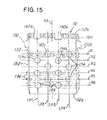
- FIG. 15 is a developed view showing a generally cylindrical body of the screw element laid out in planar form to illustrate the plurality of apertures used to permit biological material to extrude or pass from inside the screw element to outside the screw element;
- FIG. 16A is a sectional view of a screw element having a single aperture that is situated in a spiral or helical;
- FIG. 16 B is a developed view of the alternative embodiment screw element shown in FIG. 16A ;
- FIG. 17A is a sectional view of a screw element in accordance with another embodiment of the invention.
- FIG. 17B is a developed plan view of the embodiment shown in FIG. 17A ;
- FIG. 18A is a sectional view of a screw element in accordance with still another embodiment
- FIG. 18B is a developed plan view of the embodiment shown in FIG. 18A ;
- FIG. 19A is a sectional view of still another embodiment of the invention.
- FIG. 19B is a developed plan view of the embodiment shown in FIG. 19A ;
- FIG. 20A is a sectional view of a screw element in accordance with yet another embodiment of the invention.
- FIG. 20B is a developed plan view of the embodiment shown in FIG. 20A , illustrating a random, staggered or uneven pattern of apertures or windows;
- FIG. 21 is a view of another embodiment showing a continuous, constant pitch thread
- FIG. 22 is a plan view of the embodiment shown in FIG. 21 ;
- FIG. 23 is a second view taken along line 23 - 23 in FIG. 21 .
- the surgical implant 10 comprises a body 11 .
- the body 11 comprises a screw head 12 having an aperture or tool attachment zone 16 .
- the tool attachment zone 16 comprises an internal wall 14 that defines the aperture or tool attachment zone 16 ( FIG. 1A ) in the form of a tool receiving aperture for receiving a screw driver 40 ( FIG. 2 ).
- the surgical implant 10 further comprises a proximal or first thread 18 , a distal or second thread 20 and an intermediate portion 22 that is not threaded and that is integral or monolithically formed with the first thread 18 and second thread 20 as shown.
- pitch distances of each of the first threads 18 and second threads 20 are different.
- a pitch distance P 1 for the distal or second threads 20 is larger than a pitch distance P 2 of the proximal or first thread 18 .
- the rotation of the first and second threads 18 and 20 results in a relative movement of a first bone B 1 , such as a lower facet bone ( FIGS. 5A-5D ), relative to a second bone B 2 , such as an upper facet bone. This results in a desired compression of the first bone B 1 against the second bone B 2 as described later herein relative to FIGS. 5A-5D .
- the body 11 of surgical implant 10 further comprises a buttressing head 24 .
- the buttressing head 24 is integrally or monolithically formed in the screw body 11 as shown.
- the buttressing head 24 is generally cylindrical and has a first surface or side 24 a and a second surface or side 24 b that are generally planar.
- the second surface or side 24 b is adjacent to an end 18 a of the first or proximal thread 18 and is associated therewith.
- the buttressing head 24 is larger in diameter than both the first and second threads 18 and 20 , and provides a buttress or stop that facilitates providing external buttressing as the first and second threads 18 and 20 compress the first bone B 1 and the second bone B 2 together.
- first thread 18 drives the second bone B 2 leftward (as viewed in FIGS. 5A-5D ) upon rotation of the body 11 , the second bone B 2 ultimately engages the second side 24 b and the first bone B 1 is driven by the second or distal thread 20 toward the second bone B 2 until they engage and are in compression.
- first and second threads 18 and 20 provide an internal compression of the first and second bones B 1 and B 2
- the surface 24 b of buttressing head 24 provides a surface 24 b against which the first bone B 1 can drive and compress the second bone B 2 , thereby providing an external compression.
- the pitch distance P 1 ( FIGS. 1 and 1A ) of the second or distal threads 20 is larger than the pitch distance P 2 of the first or proximal thread 18 which means that the first and second threads 18 and 20 drive their respective bones B 2 and B 1 (as viewed in FIG. 5A-5D ) at different leads or rates.
- the rate of driven movement of the first bone B 1 is greater than the rate of the driven movement of the second bone B 2 , as illustrated in FIGS. 5A-5D .
- the intermediate portion 22 of the body 11 is not threaded and has a diameter smaller than the diameter of the first and second threads 18 and 20 and the buttressing head 24 . This further facilitates driving the first and second bones B 1 and B 2 together.
- the surgical implant 10 further comprises a plurality of locking slots or apertures 26 , 28 , 30 and 32 ( FIG. 1B ) that are generally elongated slots or apertures located in the first threads 18 .
- the second threads 20 could also comprise one or more locking slots or apertures.
- the locking slots or apertures 26 - 32 are elongated and generally parallel to an axis of the body 11 , as best illustrated in FIG. 1A .
- the body 11 comprises locking slots or apertures 26 , 28 , 30 and 32 , that are radially spaced about an axis A ( FIG. 1A ) of the body 11 , as best illustrated in FIG. 1B .
- the locking slots or apertures 26 - 32 are generally elongated and linear, but it should be understood that they could comprise another configuration, such as a spiral or helical configuration or shape.
- the locking slots or apertures 26 - 32 facilitate allowing for bone growth over and/or into the body 11 of the surgical implant 10 after the surgical implant 10 is screwed into a patient.
- the locking slots or apertures 26 - 32 facilitate preventing the surgical implant 10 from loosening after the surgical implant 10 is screwed into the patient by providing areas for such bone growth.
- the embodiment is shown as having four locking slots or apertures 26 - 32 , but it should be appreciated that more or fewer locking slots or apertures 26 - 32 could be provided in at least one of both a plurality of the first threads 18 , the second threads 20 and/or in the intermediate portion 22 .
- the locking slots or apertures 26 - 32 are located in the first thread 18 .
- the second threads 20 may have a plurality of notched out areas 48 ( FIGS. 1-1A ) to facilitate the start of the surgical implant 10 into the first and second bones B 1 and B 2 .
- the screw head 12 comprises a third thread 34 ( FIGS. 1 , 1 A and 2 ) at the tool attachment zone 16 to allow for engagement of and connection to a surrounding or tool locking sleeve 44 ( FIG. 2 ).
- the handedness of the third thread 34 is opposite the handedness of each of the first and second threads 18 and 20 .
- the first and second threads 18 and 20 are right-handed threads
- the third thread 34 is left-handed, and vice versa
- the first and second threads 18 and 20 are left-handed
- the third thread 34 are right-handed.
- the opposite handedness facilitates preventing disengagement of the surgical implant 10 from the screw driver 40 . Note in FIG.
- the screw driver 40 comprises a male screw driver tool 42 that is received in the mating female opening in the tool attachment zone 16 and a surrounding sleeve 44 having threads 46 that mate with the third thread 34 .
- the opposite handedness of the first and second threads 18 and 20 from that of the third threads 34 facilitates preventing disengagement of the screw driver 40 from the male screw driver tool 42 .
- the sleeve 44 remains stationary during rotation of the screw driver tool 42 .
- first or proximal threads 18 have pitch distance P 2 that is less than pitch distance P 1 than the second or distal threads 20 .
- This feature causes the bone B 1 that receives the second or distal thread 20 , such as a facet joint surface, to move at a rate R 1 toward the buttressing head 24 .
- the opposing bone surface B 1 a ( FIGS. 5A and 5D ) that receives the first or proximal thread 18 moves at a rate R 2 that is slower than the rate R 1 .
- the second or distal thread 20 and the first or proximal thread 18 move opposing bone surfaces B 1 a and B 2 b , respectively, toward the buttressing head 24 at the first and second rates R 1 and R 2 until the second bone surface B 2 a , such as an opposing facet joint surface, comes into contact with the surface 24 b of the buttressing head 24 .
- rotation of the first and second threads 18 and 20 of the differing pitches results in a relative movement of the lower bone, such as a lower facet half toward an upper bone, such as the upper facet half, until the upper facet half is situated and compressed between the buttressing head 24 and the lower facet half thereby resulting in a desired compression.
- the external buttressing head 24 buttresses the compression.
- the distal end 11 a ( FIG. 1 ) of surgical implant 10 is screwed into the first bone B 1 and the proximal thread is screwed into the second bone B 2 .
- the distal thread 20 is screwed into the bone B 1 and drives it leftward (as viewed in FIGS. 5A-5C ) a distance D 1 as shown in FIGS. 5A and 5B .
- the first or proximal threads 18 are screwed into the bone B 2 and drive it relative to the buttressing head 24 leftward (as viewed in FIGS. 5A-5C ) a distance D 2 as shown in the comparison of FIGS.
- FIGS. 5A , 5 B and 5 C This relative movement of the bones B 1 and B 2 continues as illustrated in FIGS. 5C and 5D during rotation of the body 11 of surgical implant 10 until a surface B 2 a of the bone B 2 engages the buttressing head 24 and the surface B 1 a of bone B 1 engages the generally opposing surface B 2 b as illustrated in FIGS. 5C and 5D .
- the bone surface B 1 a engages the bone surface B 2 b and drives it toward the buttressing head 24 , thereby compressing the bones B 1 and B 2 together and compressing the bone B 2 against the buttressing head 24 .
- the external compression and internal compression facilitate securing the bones B 1 and B 2 together.
- the system, method and implant described herein provide a means for fusing bones, especially the facet bones of a facet joint.
- the surgical implant 10 provides additional buttressing and compression of at least one or both of the bones that are fused or secured together.
- a surgical screw implant system 110 comprises a screw element 112 for fixing a first bone 114 ( FIGS. 13 and 14 ) and a second bone 116 together.
- the surgical screw implant system 110 is particularly adapted for use with facet bones and fusion of a facet joint, but could be used with other joints as well.
- the screw element 112 comprises a generally cylindrical body or core 118 defining a biological material receiving area, hollow area or bore 120 ( FIG. 7 ).
- the generally cylindrical body or core 118 is circular in the example and comprises an inner surface wall 122 and an outer surface or wall 124 . Note that the inner surface wall 122 defines the biological material receiving area, hollow area or bore 120 .
- the outer surface or wall 124 comprises at least one or a plurality of screw thread zones 128 and 130 that define first and second screw threads 132 and 134 , respectively.
- first and second screw threads 132 and 134 have different thread pitches, but they could be the same.
- An embodiment shown in FIGS. 21 and 22 illustrate a single thread traversing an entire length of the screw. This embodiment will be described later herein.
- the screw element 112 comprises a tool-receiving end 112 a ( FIG. 8 ) and an end or screw tip 112 b as shown.
- the tool-receiving end 112 a comprises a generally U-shaped channel 136 ( FIG. 8 ) defined by a first generally U-shaped wall 140 a and a second U-shaped wall 140 b ( FIG. 6 ).
- the tool-receiving end 112 a comprises an inner wall 112 a 1 ( FIG.
- the end or screw tip 112 b ( FIG. 7 ) comprises an inner wall 112 b 1 that defines an opening or aperture 144 ( FIG. 7 ) that also opens into the biological material receiving area, hollow area or bore 120 .
- the screw element 112 has been shown having the inner wall 112 b 1 that defines the opening or aperture 144 , it should be understood that the screw could be closed at this end. In the illustration being described, however, the opening or aperture 144 and the biological material receiving area, hollow area or bore 120 defines a lumen in the generally cylindrical body or core 118 .
- first and second screw threads 132 and 134 in the at least one or plurality of screw thread zones 128 , 130 , respectively, could have the same pitch and/or one of them could extend along an entire length of the outer surface or wall 124 .
- the first and second screw threads 132 and 134 could have different pitches similar to the embodiment described earlier herein relative to FIGS. 1-5D .
- the first screw thread 132 could comprise a thread pitch that is smaller than a thread pitch of the second screw thread 134 as shown.
- the first thread pitch and the second thread pitch are different so that the first screw thread 132 may threadably engage and drive the first bone 114 to be fused at a first rate and the second screw thread 134 may threadably engage and drive the second bone 116 to be fused toward the first bone 114 at a second rate, wherein the second rate is greater than the first rate.
- first screw threads 132 are proximal threads and the second screw threads 134 are distal threads, with the first and second screw threads 132 , 134 driving the first and second bones 114 and 116 , respectively, toward a buttressing head 150 which is similar in design and function as the buttressing head 24 described earlier herein relative to the embodiment in FIGS. 1-5D .
- the buttressing head 150 comprises an engaging surface 150 a ( FIG. 9 ) against which the first bone 114 engages when the surgical screw implant system 110 is screwed into bone.
- the buttressing head 150 comprises a diameter D 1 that is slightly larger than the diameter D 2 of the largest of the first or second screw threads 132 and 134 so that the engaging surface 150 a extends past the first screw threads 132 as shown. This enables the engaging surface 150 a to provide an external platen or external buttress engaging surface 150 a against which the first bone 114 may be driven when the surgical screw implant system 110 is screwed into bone.
- the engaging surface 150 a provides an external buttress against which the first bone 114 may be driven.
- the screw element 112 comprises a smooth intermediate area or portion 152 that couples the first and second screw threads 132 and 134 as shown.
- the intermediate area or portion 152 is generally smooth and not threaded to facilitate the second bone 116 ( FIG. 13 ) being driven into engagement with the first bone 114 similar to the first embodiment and as illustrated in FIGS. 5A-5D .
- the biological material receiving area, hollow area or bore 120 extends through an entire longitudinal length of the generally cylindrical body or core 118 and defines the lumen therein for receiving osteobiological or biological material BM ( FIG. 10 ).
- the types of materials that can be inserted are bone graft from the patient (autograft), bone graft from a cadaver (allograft), bone components, or synthetic materials which can cause adjacent bone to grow (osteoinductive materials), or allow adjacent bone to grow into the material (osteoconductive materials).
- Other examples include various phosphate, carbonate or silicate compounds.
- engineered peptides, such as bone morphogenic protein (BMP) can be used.
- the biological material receiving area, hollow area or bore 120 is elongated and is coaxial with a longitudinal screw axis SA ( FIG. 6 ) of the screw element 112 .
- the end or screw tip 112 b is open by the opening or aperture 144 , but it could be closed so that the biological material receiving area, hollow area or bore 120 would only extend partially through the screw element 112 .
- the screw element 112 is adapted to receive biological material BM for the promotion of osteosynthesis or fusing of the first bone 114 to the second bone 116 while substantially simultaneously mechanically fixing the first and second bones 114 and 116 together with the first and second screw threads 132 and 134 , respectively.
- the generally cylindrical body or core 118 is fenestrated and comprises at least one or a plurality of windows or apertures 154 as shown.
- the embodiment will be described showing a plurality of windows, but it should be understood and as mentioned that a single window or aperture could be provided in the generally cylindrical body or core 118 .
- a single continuous window such as a rectangular elongated window, helical or spiral window or other aperture in the generally cylindrical body or core 118 could be provided.
- Various illustrations of the plurality of windows are shown and described later herein relative to FIGS. 16A-20B .
- the generally cylindrical body or core 118 comprises the plurality of windows or apertures 154 as mentioned.
- the plurality of windows or apertures 154 are defined by a plurality of internal walls 112 c as illustrated in FIGS. 8 and 9 .
- the at least one or plurality of windows or apertures 154 permit the biological material BM ( FIG. 11 ) to pass through, extrude or extend radially from the biological material receiving area, hollow area or bore 120 and through the plurality of windows or apertures 154 and the opening or aperture 144 at the screw tip 112 b to adjacent surrounding bone.
- biological material BM may pass from the biological material receiving area, hollow area or bore 120 and through the plurality of windows or apertures 154 and into engagement with the first and second bones 114 and 116 to permit the biological material BM to engage and fuse the first and second bones 114 and 116 and a joint 117 ( FIG. 13 ) between them.
- the biological material receiving area, hollow area or bore 120 is adapted to receive the biological material BM and to provide a fusion mass transferring across or even into a joint, such as a facet joint 117 ( FIG. 13 ), and infusion with each of the first and second bones 114 and 116 .
- the surgical screw implant system 110 provides or is adapted to fix a plurality of bones, such as the first bone 114 and the second bone 116 , and substantially simultaneously, to fuse the plurality of bones together and provide a fusion mass between them or across the joint 117 .
- the plurality of windows or apertures 154 are spaced about the screw axis SA as illustrated.
- the plurality of windows or apertures 154 are similar shapes and circular and spaced longitudinally and radially as illustrated in FIGS. 6 and 9 .
- the illustration shown shows that the plurality of windows or apertures 154 are spaced substantially evenly, longitudinally or circumferentially, it should be understood that they could be different shapes and spaced or staggered in another orientation, such as in an uneven orientation or a staggered orientation as illustrated in FIGS. 20A-20B .
- FIG. 15 illustrates a developed or planar view of the screw element 112 shown in FIGS. 6-9 and the layout or position of the plurality of windows or apertures 154 in the generally cylindrical body or core 118 .
- the plurality of windows or apertures 154 comprise a plurality of apertures that lie in radial or horizontal planes, such as a first radial plane R 1 , a second radial plane R 2 , a third radial plane R 3 , a fourth radial plane R 4 , a fifth radial plane R 5 and a sixth radial plane R 6 and so on.
- the plurality of windows or apertures 154 comprise some apertures 154 that lie in a first longitudinal plane LP 1 , a second longitudinal plane LP 2 , a third longitudinal plane LP 3 and a fourth longitudinal plane LP 4 .
- the plurality of windows or apertures 154 that lie in the longitudinal planes LP 1 , LP 2 , LP 3 and LP 4 are spaced longitudinally and generally parallel to the screw axis SA as shown.
- the apertures 154 lying in the longitudinal planes LP 1 and LP 3 also lie in a common or radial plane, so that, for example, the window or aperture 154 a in longitudinal plane LP 1 is situated along the same radial plane R 2 as the window or aperture 154 b as shown.
- some of the plurality of windows or apertures 154 that lie in the longitudinal planes LP 2 and LP 4 are spaced and lie in substantially the same or common radial planes as illustrated.
- the plurality of windows or apertures 154 in the longitudinal planes LP 1 and LP 3 are staggered or offset relative to the plurality of windows or apertures 154 in the longitudinal planes LP 2 and LP 4 .
- the apertures 154 that lie in the radial planes R 1 , R 3 and R 5 are offset or staggered relative to the plurality of windows or apertures 154 that lie in the radial planes R 2 and R 4 and R 6 .
- the staggered or offset configuration of the plurality of windows or apertures 154 facilitate biological material BM being passed through, expanded or extruded from the biological material receiving area, hollow area or bore 120 in multiple and different radial directions and into adjacent bone, which further facilitates fusion.
- apertures 154 lie in each radial plane R 1 -R 6 and each longitudinal plain LP 1 -LP 4 , but more or fewer apertures could be provided.
- the apertures are shown as having a common size, but they could have different sizes or shapes as illustrated in FIGS. 17A-20B . As mentioned earlier, a single aperture could be used having a shape that facilitates extrusion.
- the plurality of apertures 154 that are defined by the plurality of interior walls 112 c , respectively, are generally circular, elliptical, rectangular, hexagonal, polygonal or other desired shapes.
- at least one or a plurality of apertures 154 could be an elongated (as shown in FIGS. 16A-17B ) or continuous wall that extends along the longitudinal axis or spiral or helix about the axis if desired.
- FIGS. 16A-20B illustrate other exemplary shapes, sizes and patterns of apertures 154 .
- FIGS. 16A-16B illustrate a generally rectangular aperture 154 that defines a spiral or helical aperture about the screw axis SA of the screw element 112 .
- FIGS. 17A-17B illustrate a plurality of elongated apertures that having axes that are generally parallel to the screw axis SA.
- FIGS. 18A-18B illustrate still another example aperture 154 size and pattern wherein a plurality of square or even rectangular apertures are situated such that their axes lie in planes that are generally perpendicular to the screw axis SA.
- FIGS. 19A-19B illustrate still another example of the plurality of apertures 154 having different shapes.
- FIGS. 20A-20B illustrate a plurality of apertures having different shapes and that are situated, for example, in a random or staggered pattern.
- the generally cylindrical body or core 118 could have the plurality of windows or apertures 154 that are staggered, spaced unevenly, of different shapes or sizes, spaced longitudinally or spaced circumferentially about the axis SA of the core.
- At least one or a plurality of the plurality of windows or apertures 154 extend through at least one or both of the first screw threads 132 and second screw threads 134 as illustrated. Also, at least one or a plurality of windows or apertures 154 may extend through the intermediate portion 152 of the generally cylindrical body or core 118 as shown. In one embodiment, it is desirable to maximize the open area defined by the plurality of windows or apertures 154 , so long as the implant is not mechanically weakened.
- the biological material BM may be provided in the biological material receiving area, hollow area or bore 120 and extruded or passed through at least one or a plurality of windows or apertures 154 , and the opening or aperture 144 so that the biological material BM may engage and fuse with bones situated outside the at least one or a plurality of windows or apertures 154 and opening or aperture 144 , thereby facilitating fusing of at least or one or a plurality of the first and second bones 114 and 116 with the biological mass inside the biological material receiving area, hollow area or bore 120 .
- the screw element 112 may facilitate and provide a system or means for injecting the biological material BM and forcing it against and into engagement with the first and second bones 114 and 116 , and also provide a system or means for injecting the biological material BM into a joint 117 between the first and second bones 114 and 116 , which also facilitates fusing of the first and second bones 114 and 116 .
- each of the plurality of windows or apertures 154 are adapted and sized to permit the biological material BM being used to be extruded generally laterally or radially from the screw element 112 so that the biological material BM may come into contact and fuse with any bone situated outside the plurality of windows or apertures 154 .
- the plurality of windows or apertures 154 extend or traverse through at least one or both of the first and second screw threads 132 and 134 .
- the plurality of threads and longitudinal planes LP 2 and LP 4 that lie in the radial plane R 1 traverse or pass through the first screw thread 132 .
- the plurality of windows or apertures 154 that lie in the longitudinal planes LP 1 and LP 3 also lie in the radial plane R 6 pass through the second screw threads 134 as shown.
- the plurality of apertures 154 that lie in the longitudinal planes LP 2 and LP 4 and in the radial plane R 3 traverse only through the intermediate portion 152 .
- the staggered and longitudinal and radial arrangement of the plurality of windows or apertures 154 facilitates fusion because it illustrates one maximization of the window area.
- the generally cylindrical body or core 118 has been shown as being generally circular in cross-section, but it could comprise other shapes as well, so long as it can be threaded and screwed into bone.
- the tool attachment zone 160 ( FIG. 7 ) at the tool-receiving end 112 a .
- the tool attachment zone 160 comprises a plurality of threads 164 in the tool-receiving end 112 a .
- the plurality of threads 164 allow for engagement and locking of an introducer or inserter tool 166 ( FIGS. 12 and 13 ) to the screw element 112 .
- the introducer or inserter tool 166 is adapted to be both a screw element 112 driver and a device or means for placement or insertion of biological material BM into the lumen or biological material receiving area, hollow area or bore 120 of the screw element 112 .
- the introducer or inserter tool 166 comprises a sleeve 168 that has an end 168 a that comprises a plurality of threads 170 as illustrated in FIG. 12 .
- the threads 164 have a handedness that is opposite the handedness of the first and second screw threads 132 and 134 and similar to the embodiment described earlier herein relative to FIGS. 1-5D .
- the mating threads 170 of the sleeve 168 of the tool 166 also have a handedness that mate with the threads 164 .
- the handedness is left-handedness so that when the tool is removed from the screw element 112 , it is rotated in a direction that is common with a direction of rotation when the screw element 112 is being screwed into the first and second bones 114 and 116 .
- the introducer or inserter tool 166 has an interior guide sleeve 172 having an inner wall 174 that defines an aperture or internal bore 176 for receiving biological material BM and/or other tools (not shown).
- the guide sleeve 172 comprises an end 172 a having a beveled surface 178 that facilitates guiding and introducing the biological material BM or tools into the aperture or internal bore 176 .
- the surgical screw implant system 110 may comprise, for example, a funnel 180 for receiving the biological material BM and guiding it into the aperture or internal bore 176 .
- the guide sleeve 172 comprises a plurality of forks, aligning guides, coupling prongs or means 182 , 184 ( FIG. 11 ) that are received in the generally U-shaped openings defined by the generally U-shaped walls 140 a and 140 b , respectively.
- the plurality of forks, aligning guides, coupling prongs or means 182 , 184 are adapted to enable a rotational force or torque to be applied to the screw element 112 in order to screw it into the first and second bones 114 and 116 .
- the introducer or inserter tool 166 comprises the outer sleeve 168 that threadably engages the screw element 112 and holds it in the introducer or inserter tool 166 during insertion.
- a tip or end 185 of guide sleeve 172 is received in the aperture and inside inner wall 112 a 1 ( FIG. 9 ) of end 112 a .
- the aperture or bore 176 to be in communication with the opening or aperture 144 and the biological material receiving area, hollow area or bore 120 so that when the biological material BM is introduced into the aperture or bore 176 , it is guided through the guide sleeve 172 of the introducer or inserter tool 166 and into the biological material receiving area, hollow area or bore 120 of screw element 112 .
- the biological material BM may be loaded into the screw element 112 outside of the patient or may be loaded into the screw element 112 after the screw element 112 is partially or fully positioned and screwed into the first and second bones 114 and 116 .
- a portion of biological material BM may be inserted into the biological material receiving area, hollow area or bore 120 before or after the introducer or inserter tool 166 is mounted onto the generally cylindrical body or core 118 , but preferably it is inserted after the screw element 112 has been mounted and fixed in the patient and the tool 166 is mounted to the screw element 112 .
- the aperture or bore 176 in the introducer or inserter tool 166 traverses its entire length and is sized and adapted to introduce the biological material BM into the biological material receiving area, hollow area or bore 120 .
- the tool 166 provides the function of not only rotatably driving the screw element 112 , but also providing an apparatus and means for inserting the biological material BM into the biological material receiving area, hollow area or bore 120 of the generally cylindrical body or core 118 .
- the tool 166 is, therefore, adapted to permit placement and screwing of the generally cylindrical body or core 118 in at least one or a plurality of the first bone 114 or second bone 116 and insertion of the biological material BM into the biological material receiving area, hollow area or bore 120 percutaneously through a single incision in a patient's skin. This provides for a desired minimally invasive surgery. It should be understood, however, that multiple incisions may be used as well. Devices of the past did permit percutaneous insertion of an implant, and they did not permit percutaneous insertion of the biologic into the implant, unlike the embodiments being described herein.
- the surgical screw implant system 110 may further comprise a rod or ramrod 186 having an engaging or ramming end 188 and a handle 190 as shown in FIGS. 10 and 12 .
- the ram or ramrod 186 has a diameter that is slightly smaller than the diameter of the inner wall 174 and therefore can be inserted therein to force any biological material BM in the aperture 176 downward (as viewed in FIG. 12 ) and into the biological material receiving area, hollow area or bore 120 whereupon it may be packed.
- This ramming action facilitates forcing the biological material BM into the generally cylindrical body or core 118 so that at least some of the biological material BM can pass and/or into the biological material receiving area, hollow area or bore 120 of the generally cylindrical body or core 118 and through at least one or a plurality of windows or apertures 154 and apertures 142 and 144 .
- the biological material BM may be placed in the generally cylindrical body or core 118 either before or after the screw is screwed into the first and second bones 114 and 116 , but preferably is inserted after the screw is mounted in the patient.
- a screw 200 having a continuous flight or thread 202 ( FIG. 23 ).
- the screw 200 comprises a wall 204 that defines a continuous lumen 206 that extends the longitudinal length of the screw 200 .
- the screw 200 comprises a head area 200 a having a plurality of generally U-shaped walls 208 that define a plurality of female slots 210 .
- the slots 210 are situated approximately 120 degrees apart and are adapted to receive a tool 212 ( FIG. 22 ) having an end 212 a for rotatably driving the screw 200 .
- This embodiment also comprises a plurality of interior walls 214 that, like prior embodiments, define a plurality of windows 216 as shown.
- a body 201 of the screw 200 is fenestrated and comprises at least one or a plurality of windows which could have one or more of the features described earlier herein relative to the previous embodiments.
- the windows 216 could also be adapted in shape as referred to in prior embodiments, such as the embodiments shown in FIGS. 15-20B .
- the screw 200 in the illustration shown in FIGS. 21-23 comprises the continuous thread or flight 202 that extends the longitudinal length of the outer surface 218 of the screw 200 .
- this embodiment could also comprise an interrupted thread or multiple threads of different pitches and have one or more of the features described earlier herein relative to the embodiments of FIGS. 1-20 .
- the screw 200 comprises an anti-rotation device surface or stop 220 .
- the anti-rotation device surface or stop 220 comprises a plurality of unidirectional teeth or barbs which prevent backout or rotation of the screw 200 once it is screwed into bone.
- a unique feature of this embodiment is that at least a portion of the walls 214 that define the plurality of apertures or windows 216 are in continuity with the unidirectional teeth or barbs to increase the anti-backout surface.
- the anti-backout barbs or teeth 220 such as the teeth 222 , 224 and 226 associated with window 216 a are integrally formed with the wall 214 a that defines the window 216 a.
- the screw 200 comprises the thread 202 having a thread diameter that changes during and for each revolution around the axis of the screw 200 , including, but not limited to between windows so that the thread 202 has a major diameter DM 1 ( FIG. 23 ) that is slightly larger than a minor diameter DM 2 .
- the anti-rotation stop surfaces 228 permit rotational movement of the screw 200 in a clock-wise direction, but prevent the screw 200 from rotating in a counter clock-wise direction once the screw 200 is placed in the patient.
- the minor diameter DM 2 is generally situated or begins at an edge, such as edge 216 a , associated with wall surface 214 a of the plurality of windows or apertures 216 .
- the diameter of the screw thread or flight 202 gets progressively larger until it reaches the major diameter DM 1 .
- the anti-backout shoulders, stops, barbs or teeth coincide and are generally coplanar and in communication with or aligned with the wall 214 a of the window 216 .
- the major diameter DM 1 of the screw thread or flight 230 generally becomes aligned with the wall 214 a as illustrated and defines a stop surface 225 that has an area that is larger than an area of stop surface 228 .
- this enables the wall 214 a to be in communication with the anti-rotation stop surfaces 228 which increases the anti-backout surface.
- the wall 214 a cooperates with the surface area of the anti-rotation stop surfaces 225 and provides an increased or improved surface area for engaging bone and preventing rotation and backout of the screw 200 .
- the screw thread or flight 230 is uninterrupted and comprises a plurality of anti-rotation stop surfaces 228 that are situated approximately 120 degrees apart for each revolution about the axis of the screw 200 . It should be understood that more or fewer of the anti-rotation stop surfaces 228 could be provided if desired.
- the anti-rotation surfaces, shoulders, stops or barbs such as surfaces 225 and 228
- surfaces 225 and 228 are generally planar and are generally perpendicular to the screw flight or thread 202 and lie in an imaginary plane(s) that are generally parallel to an axis of the screw 200 .
- the surfaces 225 and 228 are generally planar and are co-planar and lie in a common imaginary plane.
- the surfaces 225 of the shoulders, barbs or teeth that are adjacent a window area 216 such as the shoulders, barbs or teeth 222 , 224 and 226 , are also generally co-planar with at least a portion, such as wall 214 a , of the wall 214 .
- the shoulders, stops or barbs 228 also facilitate anti-rotation or backout.
- the imaginary planes in which that the shoulders, stops or barbs 225 and 228 lie is generally parallel to an axis of the screw 200 and generally perpendicular to the thread 202 axis.
- the following steps of using the system 110 may be performed by a surgeon:
- the surgical implant system comprises a screw element which, in its preferred embodiment, is percutaneously placed into the facet or other joints of adjacent vertebra.
- the screw element 112 further comprises a hollow and fenestrated core for the placement of biological material BM for the promotion of osteosynthesis.
- the system further comprises a detachable instrument tool 166 or means to drive said screw element 112 and inject biological material into the facet joint and screw element 112 via said fenestrated core.
- the introducer/inserter tool 166 or component functions as both a screwdriver and means for placement of biologic material BM into the lumen of the screw.
- the tip of this component has a coupling means to transmit torque to the screw for insertion.
- the introducer/inserter component further comprises the central bore 176 which is contiguous with the fenestrated lumen of the screw component.
- This central bore 176 allows for the injection of the osteobiologic or biologic material BM to promote fusion. This material then enters the screw component and extrudes through the aperture 144 of screw tip 112 b and lateral fenestrations or windows 154 to create a contiguous fusion zone incorporating the adjacent facet bodies.
Abstract
Description
-
- making an incision in a patient's skin;
- inserting the
screw system 110 through the incision so that in traverses the joint 117 or intersection between the first andsecond bones - using the
tool 166 for rotatably driving thescrew element 112 into thefirst bone 114 and thesecond bone 116 to fix them together; - inserting biological material BM into the tool before withdrawing the
tool 166 after the using step; and - driving the biological material BM through the
tool sleeve 172 and into the screw element 112 (e.g., by use of the ramrod 186) so that the biological material BM can engage the first andsecond bones second bones
Claims (46)
Priority Applications (4)
| Application Number | Priority Date | Filing Date | Title |
|---|---|---|---|
| US13/413,021 US8945193B2 (en) | 2010-07-20 | 2012-03-06 | Minimally invasive spinal facet compression screw and system for bone joint fusion and fixation |
| EP13710163.0A EP2822489A1 (en) | 2012-03-06 | 2013-02-25 | Minimally invasive spinal facet compression screw and system for bone joint fusion and fixation |
| PCT/US2013/027588 WO2013134004A1 (en) | 2012-03-06 | 2013-02-25 | Minimally invasive spinal facet compression screw and system for bone joint fusion and fixation |
| US14/594,445 US9265540B2 (en) | 2010-07-20 | 2015-01-12 | Minimally invasive spinal facet compression screw and system for bone joint fusion and fixation |
Applications Claiming Priority (3)
| Application Number | Priority Date | Filing Date | Title |
|---|---|---|---|
| US36590610P | 2010-07-20 | 2010-07-20 | |
| US13/184,862 US8992587B2 (en) | 2010-07-20 | 2011-07-18 | Spinal facet compression screw with variable pitch thread zones and buttress head |
| US13/413,021 US8945193B2 (en) | 2010-07-20 | 2012-03-06 | Minimally invasive spinal facet compression screw and system for bone joint fusion and fixation |
Related Parent Applications (2)
| Application Number | Title | Priority Date | Filing Date |
|---|---|---|---|
| US13/184,862 Continuation-In-Part US8992587B2 (en) | 2010-07-20 | 2011-07-18 | Spinal facet compression screw with variable pitch thread zones and buttress head |
| US13/184,862 Continuation US8992587B2 (en) | 2010-07-20 | 2011-07-18 | Spinal facet compression screw with variable pitch thread zones and buttress head |
Related Child Applications (1)
| Application Number | Title | Priority Date | Filing Date |
|---|---|---|---|
| US14/594,445 Continuation US9265540B2 (en) | 2010-07-20 | 2015-01-12 | Minimally invasive spinal facet compression screw and system for bone joint fusion and fixation |
Publications (2)
| Publication Number | Publication Date |
|---|---|
| US20120197311A1 US20120197311A1 (en) | 2012-08-02 |
| US8945193B2 true US8945193B2 (en) | 2015-02-03 |
Family
ID=47891967
Family Applications (2)
| Application Number | Title | Priority Date | Filing Date |
|---|---|---|---|
| US13/413,021 Active US8945193B2 (en) | 2010-07-20 | 2012-03-06 | Minimally invasive spinal facet compression screw and system for bone joint fusion and fixation |
| US14/594,445 Active US9265540B2 (en) | 2010-07-20 | 2015-01-12 | Minimally invasive spinal facet compression screw and system for bone joint fusion and fixation |
Family Applications After (1)
| Application Number | Title | Priority Date | Filing Date |
|---|---|---|---|
| US14/594,445 Active US9265540B2 (en) | 2010-07-20 | 2015-01-12 | Minimally invasive spinal facet compression screw and system for bone joint fusion and fixation |
Country Status (3)
| Country | Link |
|---|---|
| US (2) | US8945193B2 (en) |
| EP (1) | EP2822489A1 (en) |
| WO (1) | WO2013134004A1 (en) |
Cited By (44)
| Publication number | Priority date | Publication date | Assignee | Title |
|---|---|---|---|---|
| US20130211468A1 (en) * | 1993-01-21 | 2013-08-15 | Acumed Llc | Axial tension screw |
| US20140222087A1 (en) * | 2012-11-13 | 2014-08-07 | Louis E. Greenberg | Orthopedic implant having non-circular cross section and method of use thereof |
| US20150127052A1 (en) * | 2010-07-20 | 2015-05-07 | X-Spine Systems, Inc. | Minimally invasive spinal facet compression screw and system for bone joint fusion and fixation |
| US9039743B2 (en) | 2004-08-09 | 2015-05-26 | Si-Bone Inc. | Systems and methods for the fusion of the sacral-iliac joint |
| US9044321B2 (en) | 2012-03-09 | 2015-06-02 | Si-Bone Inc. | Integrated implant |
| US9375323B2 (en) | 2004-08-09 | 2016-06-28 | Si-Bone Inc. | Apparatus, systems, and methods for achieving trans-iliac lumbar fusion |
| US9492201B2 (en) | 2004-08-09 | 2016-11-15 | Si-Bone Inc. | Apparatus, systems and methods for achieving anterior lumbar interbody fusion |
| US20170065312A1 (en) * | 2015-09-05 | 2017-03-09 | Centric Medical, LLC | Orthopedic Implants With Variable Angle Bone Screw Locking |
| US9662157B2 (en) | 2014-09-18 | 2017-05-30 | Si-Bone Inc. | Matrix implant |
| US9839448B2 (en) | 2013-10-15 | 2017-12-12 | Si-Bone Inc. | Implant placement |
| US9936983B2 (en) | 2013-03-15 | 2018-04-10 | Si-Bone Inc. | Implants for spinal fixation or fusion |
| US9949843B2 (en) | 2004-08-09 | 2018-04-24 | Si-Bone Inc. | Apparatus, systems, and methods for the fixation or fusion of bone |
| US10052140B2 (en) | 2016-10-05 | 2018-08-21 | Stryker European Holdings I, Llc | Apparatus and method for fenestrated screw augmentation |
| US10166033B2 (en) | 2014-09-18 | 2019-01-01 | Si-Bone Inc. | Implants for bone fixation or fusion |
| US20190070009A1 (en) * | 2017-09-05 | 2019-03-07 | ExsoMed Corporation | Small bone tapered compression screw |
| US10363140B2 (en) | 2012-03-09 | 2019-07-30 | Si-Bone Inc. | Systems, device, and methods for joint fusion |
| US10376206B2 (en) | 2015-04-01 | 2019-08-13 | Si-Bone Inc. | Neuromonitoring systems and methods for bone fixation or fusion procedures |
| US10426533B2 (en) | 2012-05-04 | 2019-10-01 | Si-Bone Inc. | Fenestrated implant |
| US10582957B2 (en) | 2014-09-19 | 2020-03-10 | Crossroads Extremity Systems, Llc | Bone fixation implant and means of fixation |
| US10631905B2 (en) * | 2017-10-31 | 2020-04-28 | Sicage Llc | Bone cage with helically arranged fenestrations |
| US10758283B2 (en) * | 2016-08-11 | 2020-09-01 | Mighty Oak Medical, Inc. | Fixation devices having fenestrations and methods for using the same |
| USD904615S1 (en) | 2017-10-31 | 2020-12-08 | Sicage Llc | Bone screw |
| US10856919B2 (en) | 2016-02-22 | 2020-12-08 | Life Spine, Inc. | Lateral spine plate with set screw locking of bone screws |
| US10856922B2 (en) | 2017-06-07 | 2020-12-08 | Warsaw Orthopedic, Inc. | Spinal implant system and method |
| US11116519B2 (en) | 2017-09-26 | 2021-09-14 | Si-Bone Inc. | Systems and methods for decorticating the sacroiliac joint |
| US20210290346A1 (en) * | 2018-11-06 | 2021-09-23 | Huwais IP Holding LLC | Autografting tool for deep reach applications |
| US11147681B2 (en) | 2017-09-05 | 2021-10-19 | ExsoMed Corporation | Small bone angled compression screw |
| US11147602B2 (en) | 2017-05-04 | 2021-10-19 | Warsaw Orthopedic, Inc. | Spinal implant system and method |
| US11147688B2 (en) | 2013-10-15 | 2021-10-19 | Si-Bone Inc. | Implant placement |
| US11160592B2 (en) | 2018-10-18 | 2021-11-02 | Biedermann Technologies Gmbh & Co. Kg | Method of using bone plate with polyaxial injection screws |
| US11172969B2 (en) * | 2020-01-28 | 2021-11-16 | Loubert S. Suddaby | Fusion device |
| US11234830B2 (en) | 2019-02-14 | 2022-02-01 | Si-Bone Inc. | Implants for spinal fixation and or fusion |
| US11291477B1 (en) | 2021-05-04 | 2022-04-05 | Warsaw Orthopedic, Inc. | Dorsal adjusting implant and methods of use |
| US11291487B2 (en) * | 2018-12-21 | 2022-04-05 | Azurmeds Inc. | Screw fixation device, fixation kit and fixation method |
| US11369419B2 (en) | 2019-02-14 | 2022-06-28 | Si-Bone Inc. | Implants for spinal fixation and or fusion |
| US11432848B1 (en) | 2021-05-12 | 2022-09-06 | Warsaw Orthopedic, Inc. | Top loading quick lock construct |
| US11571245B2 (en) | 2019-11-27 | 2023-02-07 | Si-Bone Inc. | Bone stabilizing implants and methods of placement across SI joints |
| US11583326B2 (en) * | 2020-01-28 | 2023-02-21 | Loubert S. Suddaby | Fusion device |
| US11627998B2 (en) | 2020-12-11 | 2023-04-18 | Warsaw Orthopedic, Inc. | Head position and driver combination instrument |
| US11633292B2 (en) | 2005-05-24 | 2023-04-25 | Si-Bone Inc. | Apparatus, systems, and methods for the fixation or fusion of bone |
| US11678920B1 (en) * | 2022-09-13 | 2023-06-20 | Graziano Lopizzo | Bone screw with a slotted self-drilling tip |
| US11712270B2 (en) | 2021-05-17 | 2023-08-01 | Warsaw Orthopedic, Inc. | Quick lock clamp constructs and associated methods |
| US11752011B2 (en) | 2020-12-09 | 2023-09-12 | Si-Bone Inc. | Sacro-iliac joint stabilizing implants and methods of implantation |
| US11957391B2 (en) | 2021-11-01 | 2024-04-16 | Warsaw Orthopedic, Inc. | Bone screw having an overmold of a shank |
Families Citing this family (47)
| Publication number | Priority date | Publication date | Assignee | Title |
|---|---|---|---|---|
| US8088163B1 (en) | 2008-02-06 | 2012-01-03 | Kleiner Jeffrey B | Tools and methods for spinal fusion |
| US8366748B2 (en) | 2008-12-05 | 2013-02-05 | Kleiner Jeffrey | Apparatus and method of spinal implant and fusion |
| US9247943B1 (en) | 2009-02-06 | 2016-02-02 | Kleiner Intellectual Property, Llc | Devices and methods for preparing an intervertebral workspace |
| US10973656B2 (en) | 2009-09-18 | 2021-04-13 | Spinal Surgical Strategies, Inc. | Bone graft delivery system and method for using same |
| US9629729B2 (en) | 2009-09-18 | 2017-04-25 | Spinal Surgical Strategies, Llc | Biological delivery system with adaptable fusion cage interface |
| US20170238984A1 (en) | 2009-09-18 | 2017-08-24 | Spinal Surgical Strategies, Llc | Bone graft delivery device with positioning handle |
| US10245159B1 (en) | 2009-09-18 | 2019-04-02 | Spinal Surgical Strategies, Llc | Bone graft delivery system and method for using same |
| US8906028B2 (en) | 2009-09-18 | 2014-12-09 | Spinal Surgical Strategies, Llc | Bone graft delivery device and method of using the same |
| ES2456317T3 (en) * | 2010-02-26 | 2014-04-22 | Biedermann Technologies Gmbh & Co. Kg | Bone screw |
| US8992587B2 (en) | 2010-07-20 | 2015-03-31 | X-Spine Systems, Inc. | Spinal facet compression screw with variable pitch thread zones and buttress head |
| US10039621B2 (en) | 2011-03-23 | 2018-08-07 | Huwais IP Holding LLC | Autografting osteotome |
| US9028253B2 (en) | 2011-03-23 | 2015-05-12 | Huwais IP Holding LLC | Fluted osteotome and surgical method for use |
| WO2012170805A2 (en) * | 2011-06-09 | 2012-12-13 | Knee Creations, Llc | Instruments and devices for subchondral joint repair |
| US9173692B1 (en) * | 2012-06-15 | 2015-11-03 | Stc.Unm | Composite metal and bone orthopedic fixation devices |
| US20140058461A1 (en) * | 2012-08-27 | 2014-02-27 | Michael Black | Fenestrated Bone Screw |
| CN105120792B (en) | 2012-12-11 | 2019-09-10 | 胡瓦伊斯Ip控股有限公司 | Squeeze planting body |
| FR3001628B1 (en) * | 2013-02-05 | 2017-11-24 | Safe Orthopaedics | IMPLANTATION ASSEMBLY COMPRISING A PRE-ASSEMBLED DRIVE INSTRUMENT ON A BONE IMPLANT |
| US9636158B2 (en) | 2013-03-13 | 2017-05-02 | Blackstone Medical, Inc. | Pedicle screw with reverse spiral cut and methods thereof |
| AU2014237911B2 (en) | 2013-03-15 | 2018-02-15 | Innovision, Inc. | Bone screws and methods of use thereof |
| JP5472517B1 (en) * | 2013-07-12 | 2014-04-16 | 多摩メディカル有限会社 | Medical screw and jig for removing medical screw |
| US9308123B2 (en) * | 2013-09-16 | 2016-04-12 | Neuraxis, Llc | Methods and devices for applying localized thermal therapy |
| US10531904B2 (en) * | 2014-04-30 | 2020-01-14 | Eric D. Kolb | Bone screw with apertures |
| US9931141B2 (en) | 2014-11-26 | 2018-04-03 | Ex Technology, Llc | Method and apparatus for joint fusion |
| US10363075B2 (en) * | 2015-02-09 | 2019-07-30 | Yingze Zhang | Porous bionic internal fixation device for promoting healing of fractured bone |
| US9943340B2 (en) | 2015-02-25 | 2018-04-17 | Amendia, Inc. | Sacroiliac screw |
| US9358057B1 (en) | 2015-02-25 | 2016-06-07 | Amendia, Inc. | Sacroiliac screw |
| FR3040285B1 (en) * | 2015-08-31 | 2017-09-15 | Bpath | VERTEBRAL IMPLANT, METHOD FOR SETTING SUCH IMPLANT AND TOOL FOR IMPLANT PLACEMENT |
| USD797290S1 (en) | 2015-10-19 | 2017-09-12 | Spinal Surgical Strategies, Llc | Bone graft delivery tool |
| KR102563551B1 (en) | 2016-01-14 | 2023-08-04 | 후아이스 아이피 홀딩 엘엘씨 | Autografting tool with enhanced flute profile and methods of use |
| JP6959653B2 (en) | 2016-02-07 | 2021-11-02 | ヒューワイス アイピー ホールディング,エルエルシー | Anchor screw with compression characteristics |
| FR3048176A1 (en) * | 2016-02-26 | 2017-09-01 | Ldr Medical | SPINAL ARTHRODESIS IMPLANT SYSTEM |
| US10470807B2 (en) * | 2016-06-03 | 2019-11-12 | Stryker European Holdings I, Llc | Intramedullary implant and method of use |
| FR3052657B1 (en) * | 2016-06-21 | 2020-12-18 | Innoprod Medical | SPECIFIC INSTRUMENTATION DEDICATED TO THE PERCUTANEOUS PLACEMENT OF AN IMPLANT ALLOWING A TARGETED INJECTION |
| FR3052656A1 (en) * | 2016-06-21 | 2017-12-22 | Innoprod Medical | SPECIFIC CANNULA FOR INJECTING TO THE TRAUERS OF A DEDICATED IMPLANT |
| US10653468B2 (en) * | 2016-08-29 | 2020-05-19 | Osteomed Llc | Four corner fusion device |
| US10624734B2 (en) * | 2016-10-18 | 2020-04-21 | Arthrex, Inc. | Surgical assembly for tissue repair |
| US10821579B2 (en) * | 2016-11-07 | 2020-11-03 | Jacques Rajotte | Screw driving device for use with an impact driver |
| EP3357459A1 (en) | 2017-02-03 | 2018-08-08 | Spinal Surgical Strategies, LLC | Bone graft delivery device with positioning handle |
| US11883077B2 (en) * | 2018-02-01 | 2024-01-30 | Genesys Spine | Material directing orthopedic anchor |
| US11026735B2 (en) * | 2018-02-28 | 2021-06-08 | Premia Spine Ltd. | Bone marrow aspiration adaptor assembly |
| WO2019204562A1 (en) * | 2018-04-18 | 2019-10-24 | Wapner Peter | Removable orthopedic screws |
| US11191582B2 (en) * | 2018-05-09 | 2021-12-07 | Warsaw Orthopedic, Inc. | Bone screw and method of manufacture |
| US11832860B2 (en) | 2018-06-22 | 2023-12-05 | University Of Virginia Patent Foundation | Bone fixation system for promoting the union of a bone fracture and fusion of bones across a joint space and related methods thereof |
| US11497609B2 (en) * | 2019-04-26 | 2022-11-15 | Warsaw Orthopedic, Inc. | Retention system and method |
| DE102020006464A1 (en) * | 2020-10-21 | 2022-04-21 | Mimeo Medical Gmbh | Screw element optimized for 3D printing |
| US11553948B2 (en) * | 2021-05-20 | 2023-01-17 | University Of Utah Research Foundation | Bone fixation devices, systems, and methods |
| US11679005B1 (en) * | 2022-05-26 | 2023-06-20 | Spinal Simplicity, Llc | Implant removal tool |
Citations (118)
| Publication number | Priority date | Publication date | Assignee | Title |
|---|---|---|---|---|
| US2121193A (en) | 1932-12-21 | 1938-06-21 | Hanicke Paul Gustav Erich | Fracture clamping apparatus |
| US2382019A (en) | 1944-05-02 | 1945-08-14 | Miller Edwin August | Compound screw |
| US2472103A (en) | 1945-03-13 | 1949-06-07 | Josef H Giesen | Modified bone screw holder for surgical drills |
| US2489870A (en) | 1946-03-02 | 1949-11-29 | Dzus William | Bone fastening device |
| US2570465A (en) | 1949-08-01 | 1951-10-09 | Joseph S Lundholm | Means for fixation of hip fractures |
| US2801631A (en) | 1954-08-18 | 1957-08-06 | Charnley John | Fracture screw adjusting means |
| US3682507A (en) | 1970-06-02 | 1972-08-08 | Illinois Tool Works | Threaded fastener with stabilizing threads |
| US4059102A (en) | 1974-08-01 | 1977-11-22 | National Research Development Corporation | Bone securing devices |
| US4175555A (en) | 1977-02-24 | 1979-11-27 | Interfix Limited | Bone screw |
| US4456005A (en) | 1982-09-30 | 1984-06-26 | Lichty Terry K | External compression bone fixation device |
| US4463753A (en) | 1980-01-04 | 1984-08-07 | Gustilo Ramon B | Compression bone screw |
| US4537185A (en) | 1983-06-10 | 1985-08-27 | Denis P. Stednitz | Cannulated fixation screw |
| US4640271A (en) | 1985-11-07 | 1987-02-03 | Zimmer, Inc. | Bone screw |
| US4712957A (en) | 1985-12-11 | 1987-12-15 | Wayne Edwards | Adhesively secured fastener |
| US4858601A (en) | 1988-05-27 | 1989-08-22 | Glisson Richard R | Adjustable compression bone screw |
| US4944759A (en) | 1986-01-21 | 1990-07-31 | Joint Medical Products Corporation | Porous-coated artificial joints |
| US4959064A (en) | 1988-10-07 | 1990-09-25 | Boehringer Mannheim Corporation | Dynamic tension bone screw |
| US5019079A (en) | 1989-11-20 | 1991-05-28 | Zimmer, Inc. | Bone screw |
| US5047030A (en) | 1987-02-20 | 1991-09-10 | Klaus Draenert | Suction drainage-bone screw |
| US5116337A (en) | 1991-06-27 | 1992-05-26 | Johnson Lanny L | Fixation screw and method for ligament reconstruction |
| US5120171A (en) | 1990-11-27 | 1992-06-09 | Stuart Surgical | Bone screw with improved threads |
| US5180382A (en) | 1990-12-19 | 1993-01-19 | Synthes (U.S.A.) | Bone screw |
| US5226766A (en) | 1990-11-27 | 1993-07-13 | Stuart Surgical | Bone screw with improved threads |
| US5259398A (en) | 1989-10-26 | 1993-11-09 | Giuseppe Vrespa | Method for fixing prosthesis to bones |
| US5334204A (en) | 1992-08-03 | 1994-08-02 | Ace Medical Company | Fixation screw |
| US5375956A (en) * | 1993-03-11 | 1994-12-27 | Pennig; Dietmar | Head screw construction for use in fixing the position of an intramedullary nail |
| US5403136A (en) | 1991-06-25 | 1995-04-04 | Synthes (U.S.A.) | Threaded fastener especially for orthopaedic purposes |
| US5470334A (en) | 1991-03-05 | 1995-11-28 | Linvatec Corporation | Bioabsorbable interference bone fixation screw |
| US5492442A (en) | 1990-11-27 | 1996-02-20 | National Medical Specialty, Inc. | Bone screw with improved threads |
| US5505736A (en) | 1992-02-14 | 1996-04-09 | American Cyanamid Company | Surgical fastener with selectively coated ridges |
| US5536127A (en) * | 1994-10-13 | 1996-07-16 | Pennig; Dietmar | Headed screw construction for use in fixing the position of an intramedullary nail |
| US5562672A (en) | 1993-01-21 | 1996-10-08 | Acumed, Inc. | Tapered bone screw with continuously varying pitch |
| US5964768A (en) | 1993-01-21 | 1999-10-12 | Acumed, Inc. | Tapered bone screw with continuously varying pitch |
| US6030162A (en) | 1998-12-18 | 2000-02-29 | Acumed, Inc. | Axial tension screw |
| US6053916A (en) * | 1999-02-17 | 2000-04-25 | Moore; Michael R. | Sacroiliac implant |
| US6129730A (en) | 1999-02-10 | 2000-10-10 | Depuy Acromed, Inc. | Bi-fed offset pitch bone screw |
| US6306140B1 (en) | 2001-01-17 | 2001-10-23 | Synthes (Usa) | Bone screw |
| US20020169453A1 (en) * | 1998-08-07 | 2002-11-14 | Berger J. Lee | Cannulated internally threaded bone screw |
| US6485518B1 (en) | 1999-12-10 | 2002-11-26 | Nuvasive | Facet screw and bone allograft intervertebral support and fusion system |
| US6503252B2 (en) | 2001-02-21 | 2003-01-07 | Henrik Hansson | Bone screw, method for producing the threads thereof and drill for drilling holes therefor |
| US6540747B1 (en) | 1999-04-16 | 2003-04-01 | Nuvasive, Inc. | System for securing joints together |
| EP1302170A2 (en) | 2001-10-16 | 2003-04-16 | Inverlock Trading Limited | Dowel or screw for setting small bone fragments |
| US6551323B2 (en) | 2000-03-14 | 2003-04-22 | Hammill Manufacturing | Method of making a bonescrew |
| US20030208202A1 (en) | 2002-05-04 | 2003-11-06 | Falahee Mark H. | Percutaneous screw fixation system |
| US6648893B2 (en) | 2000-10-27 | 2003-11-18 | Blackstone Medical, Inc. | Facet fixation devices |
| US20040087948A1 (en) | 2002-08-29 | 2004-05-06 | Loubert Suddaby | Spinal facet fixation device |
| US20040097941A1 (en) * | 2002-11-20 | 2004-05-20 | Millennium Medical Technologies Inc. | Compression bone fragment wire |
| US20040254575A1 (en) | 2003-06-13 | 2004-12-16 | Obenchain Theodore G. | Method and apparatus for stabilization of facet joint |
| US20050124993A1 (en) | 2002-12-02 | 2005-06-09 | Chappuis James L. | Facet fusion system |
| US20050149030A1 (en) | 2003-12-19 | 2005-07-07 | Depuy Spine, Inc. | Facet joint fixation system |
| US20050152770A1 (en) | 2002-02-26 | 2005-07-14 | Degima Medizinprodukte Gmbh | Threaded device with improved resistance against torsion-caused breakage |
| US6979163B2 (en) * | 2001-10-05 | 2005-12-27 | Illinois Tool Works Inc. | Push-in removable fastener |
| US20060025773A1 (en) | 2001-12-04 | 2006-02-02 | Yan Yevmenenko | Headless compression screw with integrated reduction-compression instrument |
| US20060111779A1 (en) | 2004-11-22 | 2006-05-25 | Orthopedic Development Corporation, A Florida Corporation | Minimally invasive facet joint fusion |
| US20060111780A1 (en) | 2004-11-22 | 2006-05-25 | Orthopedic Development Corporation | Minimally invasive facet joint hemi-arthroplasty |
| US20060200149A1 (en) | 2005-02-22 | 2006-09-07 | Hoy Robert W | Polyaxial orhtopedic fastening apparatus |
| US20060264953A1 (en) | 2002-10-10 | 2006-11-23 | Falahee Mark H | Percutaneous translaminar facet fixation system |
| US20070112428A1 (en) | 2005-11-15 | 2007-05-17 | Zimmer Spine, Inc. | Facet repair and stabilization |
| US7223269B2 (en) | 2002-12-02 | 2007-05-29 | Chappuis James L | Facet fusion system |
| US20070233123A1 (en) * | 2006-02-21 | 2007-10-04 | Osteomed, L.P. | Bone fixation device |
| US20070233125A1 (en) | 2006-03-17 | 2007-10-04 | Nexa Orthopedics, Inc. | Bone screw with selectively securable washer |
| US20070233093A1 (en) | 2006-02-24 | 2007-10-04 | Falahee Mark H | Multilevel facet/laminar fixation system |
| US20070233092A1 (en) | 2006-02-24 | 2007-10-04 | Falahee Mark H | Dynamic/static facet fixation device and method |
| US20080234758A1 (en) | 2007-02-26 | 2008-09-25 | Depuy Spine, Inc. | Intra-facet fixation device and method of use |
| US20080255622A1 (en) | 2007-04-13 | 2008-10-16 | Depuy Spine, Inc. | Facet fixation and fusion screw and washer assembly and method of use |
| US20080255667A1 (en) | 2007-04-13 | 2008-10-16 | Horton Kenneth L | Allograft spinal facet fusion system |
| US20080255666A1 (en) | 2007-04-13 | 2008-10-16 | Depuy Spine, Inc. | Facet fixation and fusion wedge and method of use |
| US20080255618A1 (en) | 2007-04-13 | 2008-10-16 | Depuy Spine, Inc. | Articulating facet fusion screw |
| US20080255619A1 (en) | 2007-04-10 | 2008-10-16 | Schneiderman Gary A | Posterior spinal fixation with colinear facet screw |
| US20080262555A1 (en) | 2007-01-05 | 2008-10-23 | Trans1 Inc. | Percutaneous delivery of facet screws using depth control indicator |
| US20080275454A1 (en) | 2007-05-04 | 2008-11-06 | Geibel Paul T | Lumbar pedicular-facet fixation system and instrumentation |
| US7452369B2 (en) | 2004-10-18 | 2008-11-18 | Barry Richard J | Spine microsurgery techniques, training aids and implants |
| US20090036927A1 (en) | 2007-05-22 | 2009-02-05 | Tov Vestgaarden | Method and apparatus for spinal facet fusion |
| US20090036926A1 (en) | 2007-07-31 | 2009-02-05 | Zimmer Spine, Inc. | Method for stabilizing a facet joint |
| US20090036986A1 (en) | 2007-08-03 | 2009-02-05 | Zimmer Spine, Inc. | Attachment devices and methods for spinal implants |
| US20090048675A1 (en) | 2007-04-25 | 2009-02-19 | Bhatnagar Mohit K | Spinal Fusion Implants with Selectively Applied Bone Growth Promoting Agent |
| US20090054903A1 (en) | 2002-10-10 | 2009-02-26 | Mark Falahee | Bone fixation implant system and method |
| US20090076551A1 (en) | 2004-11-22 | 2009-03-19 | Petersen David A | Methods and surgical kits for minimally-invasive facet joint fusion |
| US20090093851A1 (en) | 2007-10-09 | 2009-04-09 | Osman Said G | Transfacet-Pedicle Locking Screw Fixation of Lumbar Motion Segment |
| US20090099602A1 (en) | 2007-09-11 | 2009-04-16 | Kamran Aflatoon | Method of lateral facet approach, decompression and fusion using screws and staples as well as arthroplasty |
| US20090112264A1 (en) | 2007-10-24 | 2009-04-30 | Lins Robert E | Pedicle-based facet joint fixation systems and methods |
| US20090125066A1 (en) | 2005-02-09 | 2009-05-14 | Gary Kraus | Facet stabilization schemes |
| US20090131986A1 (en) | 2007-11-19 | 2009-05-21 | David Lee | Method and apparatus for spinal facet joint fusion using irregularly shaped cortical bone implants |
| US20090163920A1 (en) | 2007-07-03 | 2009-06-25 | Stephen Hochschuler | Facet fusion implant |
| US20090177205A1 (en) | 2008-01-09 | 2009-07-09 | Providence Medical Technology, Inc. | Methods and apparatus for accessing and treating the facet joint |
| US7563275B2 (en) | 2002-10-10 | 2009-07-21 | U.S. Spinal Technologies, Llc | Bone fixation implant system and method |
| US20090187219A1 (en) | 2007-08-03 | 2009-07-23 | Neal Pachtman | Spinal Facet Joint Immobilization Systems and Methods |
| US20090192551A1 (en) | 2008-01-24 | 2009-07-30 | Jason Cianfrani | Facet Fixation Prosthesis |
| US20090216273A1 (en) | 2008-02-19 | 2009-08-27 | U. S. Spinal Technologies, L.L.C. | Curved facet joint fixation assembly and associated implantation tool and method |
| US20090234394A1 (en) | 2008-03-11 | 2009-09-17 | David Crook | Unilateral facet bolt inserter |
| US20090234397A1 (en) | 2004-11-22 | 2009-09-17 | Petersen David A | Methods and Surgical Kits for Minimally-Invasive Facet Joint Fusion |
| US20090248089A1 (en) | 2008-03-25 | 2009-10-01 | Jacofsky Marc C | Spinal facet fixation device |
| US20090248082A1 (en) | 2008-03-04 | 2009-10-01 | David Crook | Surgical systems and methods for joint fixation |
| US20090264928A1 (en) | 2004-06-10 | 2009-10-22 | Spinal Elements, Inc. | Implant and method for facet immobilization |
| US7608094B2 (en) | 2002-10-10 | 2009-10-27 | U.S. Spinal Technologies, Llc | Percutaneous facet fixation system |
| US20090270929A1 (en) | 2008-04-24 | 2009-10-29 | Loubert Suddaby | Facet joint fixation device |
| US20090275994A1 (en) | 2008-04-30 | 2009-11-05 | Phan Christopher U | Apparatus and methods for inserting facet screws |
| US20090299412A1 (en) | 2006-02-02 | 2009-12-03 | Trinity Orthopedics | Percutaneous facet joint fusion system and method |
| US20090306671A1 (en) | 2008-06-06 | 2009-12-10 | Providence Medical Technology, Inc. | Facet joint implants and delivery tools |
| US20090312800A1 (en) | 2007-07-18 | 2009-12-17 | Spinefrontier Inc | System and method for facet fixation |
| US20090312763A1 (en) | 2008-06-06 | 2009-12-17 | Mccormack Bruce M | Facet joint implants and delivery tools |
| US20090312798A1 (en) | 2008-06-16 | 2009-12-17 | Armando Varela | Transfacet fixation assembly and related surgical methods |
| US20100068003A1 (en) * | 2008-09-16 | 2010-03-18 | Frank Wagner | Anti-Cross Threading Screw |
| US20100076490A1 (en) | 2008-02-28 | 2010-03-25 | Jonathan Greenwald | Facet joint broaching instrument, implant, and associated method |
| US20100082065A1 (en) | 2008-10-01 | 2010-04-01 | Butler Michael S | Spinal Facet Fastener |
| US20100087859A1 (en) | 2008-10-03 | 2010-04-08 | Jackson Jr Darrell | Facet button assembly and related surgical methods |
| US20100094356A1 (en) | 2008-10-15 | 2010-04-15 | Armando Varela | Interlocking bone screw and washer concepts |
| US7699878B2 (en) | 2002-11-13 | 2010-04-20 | Synthes Usa, Llc | Method for locking an artificial facet between two vertebral bodies |
| US20100100135A1 (en) | 2008-10-21 | 2010-04-22 | Phan Christopher U | Bone fixation device having an expandable anchor |
| US20100114175A1 (en) | 2006-04-25 | 2010-05-06 | Warsaw Orthopedic, Inc. | Facet Fusion Implants and Methods of Use |
| EP1927322B1 (en) | 2006-12-01 | 2010-06-02 | Wright Medical Technology, Inc. | Device for positioning tubular bones |
| WO2010067363A1 (en) | 2008-12-09 | 2010-06-17 | Mazor Surgical Technologies Ltd. | Double threaded orthopedic screw |
| US20110112436A1 (en) | 2009-11-06 | 2011-05-12 | SpineSmith Partners, LP | Distraction pins for fluid aspiration |
| US20120010659A1 (en) | 2010-07-09 | 2012-01-12 | Nicholas Angert | Facet fusion implant |
| US20120010669A1 (en) | 2010-07-12 | 2012-01-12 | Depuy Spine, Inc. | Pedicular facet fusion screw with plate |
| US20120022603A1 (en) | 2010-07-20 | 2012-01-26 | X-Spine Systems, Inc. | Spinal facet compression screw with variable pitch thread zones and buttress head |
| US20120197311A1 (en) | 2010-07-20 | 2012-08-02 | X-Spine Systems, Inc. | Minimally invasive spinal facet compression screw and system for bone joint fusion and fixation |
| US8574273B2 (en) | 2009-09-09 | 2013-11-05 | Innovision, Inc. | Bone screws and methods of use thereof |
Family Cites Families (2)
| Publication number | Priority date | Publication date | Assignee | Title |
|---|---|---|---|---|
| US20130072984A1 (en) * | 2011-09-21 | 2013-03-21 | James C. Robinson | Fenestrated bone screws and methods of bone fastening and stabilization |
| US20130226239A1 (en) * | 2012-02-23 | 2013-08-29 | Moti Altarac | Facet screw and method for spinal stabilization |
-
2012
- 2012-03-06 US US13/413,021 patent/US8945193B2/en active Active
-
2013
- 2013-02-25 WO PCT/US2013/027588 patent/WO2013134004A1/en active Application Filing
- 2013-02-25 EP EP13710163.0A patent/EP2822489A1/en not_active Withdrawn
-
2015
- 2015-01-12 US US14/594,445 patent/US9265540B2/en active Active
Patent Citations (138)
| Publication number | Priority date | Publication date | Assignee | Title |
|---|---|---|---|---|
| US2121193A (en) | 1932-12-21 | 1938-06-21 | Hanicke Paul Gustav Erich | Fracture clamping apparatus |
| US2382019A (en) | 1944-05-02 | 1945-08-14 | Miller Edwin August | Compound screw |
| US2472103A (en) | 1945-03-13 | 1949-06-07 | Josef H Giesen | Modified bone screw holder for surgical drills |
| US2489870A (en) | 1946-03-02 | 1949-11-29 | Dzus William | Bone fastening device |
| US2570465A (en) | 1949-08-01 | 1951-10-09 | Joseph S Lundholm | Means for fixation of hip fractures |
| US2801631A (en) | 1954-08-18 | 1957-08-06 | Charnley John | Fracture screw adjusting means |
| US3682507A (en) | 1970-06-02 | 1972-08-08 | Illinois Tool Works | Threaded fastener with stabilizing threads |
| US4059102A (en) | 1974-08-01 | 1977-11-22 | National Research Development Corporation | Bone securing devices |
| US4175555A (en) | 1977-02-24 | 1979-11-27 | Interfix Limited | Bone screw |
| US4463753A (en) | 1980-01-04 | 1984-08-07 | Gustilo Ramon B | Compression bone screw |
| US4456005A (en) | 1982-09-30 | 1984-06-26 | Lichty Terry K | External compression bone fixation device |
| US4537185A (en) | 1983-06-10 | 1985-08-27 | Denis P. Stednitz | Cannulated fixation screw |
| US4640271A (en) | 1985-11-07 | 1987-02-03 | Zimmer, Inc. | Bone screw |
| US4712957A (en) | 1985-12-11 | 1987-12-15 | Wayne Edwards | Adhesively secured fastener |
| US4944759A (en) | 1986-01-21 | 1990-07-31 | Joint Medical Products Corporation | Porous-coated artificial joints |
| US5047030A (en) | 1987-02-20 | 1991-09-10 | Klaus Draenert | Suction drainage-bone screw |
| US4858601A (en) | 1988-05-27 | 1989-08-22 | Glisson Richard R | Adjustable compression bone screw |
| US4959064A (en) | 1988-10-07 | 1990-09-25 | Boehringer Mannheim Corporation | Dynamic tension bone screw |
| US5593410A (en) | 1989-10-26 | 1997-01-14 | Vrespa; Giuseppe | Screw device for fixing prostheses to bones |
| US5259398A (en) | 1989-10-26 | 1993-11-09 | Giuseppe Vrespa | Method for fixing prosthesis to bones |
| US5019079A (en) | 1989-11-20 | 1991-05-28 | Zimmer, Inc. | Bone screw |
| US5417533A (en) | 1990-07-13 | 1995-05-23 | National Medical Specialty, Inc. | Bone screw with improved threads |
| US5226766A (en) | 1990-11-27 | 1993-07-13 | Stuart Surgical | Bone screw with improved threads |
| US5120171A (en) | 1990-11-27 | 1992-06-09 | Stuart Surgical | Bone screw with improved threads |
| US5492442A (en) | 1990-11-27 | 1996-02-20 | National Medical Specialty, Inc. | Bone screw with improved threads |
| US5180382A (en) | 1990-12-19 | 1993-01-19 | Synthes (U.S.A.) | Bone screw |
| US5470334A (en) | 1991-03-05 | 1995-11-28 | Linvatec Corporation | Bioabsorbable interference bone fixation screw |
| US5403136A (en) | 1991-06-25 | 1995-04-04 | Synthes (U.S.A.) | Threaded fastener especially for orthopaedic purposes |
| US5116337A (en) | 1991-06-27 | 1992-05-26 | Johnson Lanny L | Fixation screw and method for ligament reconstruction |
| US5505736A (en) | 1992-02-14 | 1996-04-09 | American Cyanamid Company | Surgical fastener with selectively coated ridges |
| US5334204A (en) | 1992-08-03 | 1994-08-02 | Ace Medical Company | Fixation screw |
| US5964768A (en) | 1993-01-21 | 1999-10-12 | Acumed, Inc. | Tapered bone screw with continuously varying pitch |
| US5562672A (en) | 1993-01-21 | 1996-10-08 | Acumed, Inc. | Tapered bone screw with continuously varying pitch |
| US5375956A (en) * | 1993-03-11 | 1994-12-27 | Pennig; Dietmar | Head screw construction for use in fixing the position of an intramedullary nail |
| US5536127A (en) * | 1994-10-13 | 1996-07-16 | Pennig; Dietmar | Headed screw construction for use in fixing the position of an intramedullary nail |
| US20020169453A1 (en) * | 1998-08-07 | 2002-11-14 | Berger J. Lee | Cannulated internally threaded bone screw |
| US6030162A (en) | 1998-12-18 | 2000-02-29 | Acumed, Inc. | Axial tension screw |
| US6129730A (en) | 1999-02-10 | 2000-10-10 | Depuy Acromed, Inc. | Bi-fed offset pitch bone screw |
| US6053916A (en) * | 1999-02-17 | 2000-04-25 | Moore; Michael R. | Sacroiliac implant |
| US6540747B1 (en) | 1999-04-16 | 2003-04-01 | Nuvasive, Inc. | System for securing joints together |
| US6485518B1 (en) | 1999-12-10 | 2002-11-26 | Nuvasive | Facet screw and bone allograft intervertebral support and fusion system |
| US6551323B2 (en) | 2000-03-14 | 2003-04-22 | Hammill Manufacturing | Method of making a bonescrew |
| US6648893B2 (en) | 2000-10-27 | 2003-11-18 | Blackstone Medical, Inc. | Facet fixation devices |
| US6306140B1 (en) | 2001-01-17 | 2001-10-23 | Synthes (Usa) | Bone screw |
| US6503252B2 (en) | 2001-02-21 | 2003-01-07 | Henrik Hansson | Bone screw, method for producing the threads thereof and drill for drilling holes therefor |
| US6979163B2 (en) * | 2001-10-05 | 2005-12-27 | Illinois Tool Works Inc. | Push-in removable fastener |
| EP1302170A2 (en) | 2001-10-16 | 2003-04-16 | Inverlock Trading Limited | Dowel or screw for setting small bone fragments |
| US20060025773A1 (en) | 2001-12-04 | 2006-02-02 | Yan Yevmenenko | Headless compression screw with integrated reduction-compression instrument |
| US20050152770A1 (en) | 2002-02-26 | 2005-07-14 | Degima Medizinprodukte Gmbh | Threaded device with improved resistance against torsion-caused breakage |
| US20030208202A1 (en) | 2002-05-04 | 2003-11-06 | Falahee Mark H. | Percutaneous screw fixation system |
| US20040087948A1 (en) | 2002-08-29 | 2004-05-06 | Loubert Suddaby | Spinal facet fixation device |
| US20050267480A1 (en) | 2002-08-29 | 2005-12-01 | Loubert Suddaby | Spinal facet fixation device |
| US20090054903A1 (en) | 2002-10-10 | 2009-02-26 | Mark Falahee | Bone fixation implant system and method |
| US20060264953A1 (en) | 2002-10-10 | 2006-11-23 | Falahee Mark H | Percutaneous translaminar facet fixation system |
| US8002812B2 (en) | 2002-10-10 | 2011-08-23 | Us Spine, Inc. | Bone fixation implant system and method |
| US7563275B2 (en) | 2002-10-10 | 2009-07-21 | U.S. Spinal Technologies, Llc | Bone fixation implant system and method |
| US7608094B2 (en) | 2002-10-10 | 2009-10-27 | U.S. Spinal Technologies, Llc | Percutaneous facet fixation system |
| US20090318980A1 (en) | 2002-10-10 | 2009-12-24 | U.S. Spinal Technologies, Llc | Percutaneous facet fixation system |
| US7699878B2 (en) | 2002-11-13 | 2010-04-20 | Synthes Usa, Llc | Method for locking an artificial facet between two vertebral bodies |
| US20040097941A1 (en) * | 2002-11-20 | 2004-05-20 | Millennium Medical Technologies Inc. | Compression bone fragment wire |
| US7223269B2 (en) | 2002-12-02 | 2007-05-29 | Chappuis James L | Facet fusion system |
| US20050124993A1 (en) | 2002-12-02 | 2005-06-09 | Chappuis James L. | Facet fusion system |
| US7749251B2 (en) | 2003-06-13 | 2010-07-06 | Aeolin, Llc | Method and apparatus for stabilization of facet joint |
| US20040254575A1 (en) | 2003-06-13 | 2004-12-16 | Obenchain Theodore G. | Method and apparatus for stabilization of facet joint |
| US20050149030A1 (en) | 2003-12-19 | 2005-07-07 | Depuy Spine, Inc. | Facet joint fixation system |
| US20090264928A1 (en) | 2004-06-10 | 2009-10-22 | Spinal Elements, Inc. | Implant and method for facet immobilization |
| US20090105819A1 (en) | 2004-10-18 | 2009-04-23 | Barry Richard J | Spine microsurgery techniques, training aids and implants |
| US7452369B2 (en) | 2004-10-18 | 2008-11-18 | Barry Richard J | Spine microsurgery techniques, training aids and implants |
| US8021392B2 (en) | 2004-11-22 | 2011-09-20 | Minsurg International, Inc. | Methods and surgical kits for minimally-invasive facet joint fusion |
| US20090076551A1 (en) | 2004-11-22 | 2009-03-19 | Petersen David A | Methods and surgical kits for minimally-invasive facet joint fusion |
| US20060111779A1 (en) | 2004-11-22 | 2006-05-25 | Orthopedic Development Corporation, A Florida Corporation | Minimally invasive facet joint fusion |
| US20060111780A1 (en) | 2004-11-22 | 2006-05-25 | Orthopedic Development Corporation | Minimally invasive facet joint hemi-arthroplasty |
| US7837713B2 (en) | 2004-11-22 | 2010-11-23 | Minsurg International, Inc. | Methods and surgical kits for minimally-invasive facet joint fusion |
| US20090234397A1 (en) | 2004-11-22 | 2009-09-17 | Petersen David A | Methods and Surgical Kits for Minimally-Invasive Facet Joint Fusion |
| US7708761B2 (en) | 2004-11-22 | 2010-05-04 | Minsurg International, Inc. | Spinal plug for a minimally invasive facet joint fusion system |
| US20090125066A1 (en) | 2005-02-09 | 2009-05-14 | Gary Kraus | Facet stabilization schemes |
| US7993373B2 (en) | 2005-02-22 | 2011-08-09 | Hoy Robert W | Polyaxial orthopedic fastening apparatus |
| US20060200149A1 (en) | 2005-02-22 | 2006-09-07 | Hoy Robert W | Polyaxial orhtopedic fastening apparatus |
| US20060212034A1 (en) | 2005-02-22 | 2006-09-21 | Triplett Daniel J | Polyaxial orhtopedic fastening apparatus with independent locking modes |
| US20070112428A1 (en) | 2005-11-15 | 2007-05-17 | Zimmer Spine, Inc. | Facet repair and stabilization |
| US7744630B2 (en) | 2005-11-15 | 2010-06-29 | Zimmer Spine, Inc. | Facet repair and stabilization |
| US20090299412A1 (en) | 2006-02-02 | 2009-12-03 | Trinity Orthopedics | Percutaneous facet joint fusion system and method |
| US20070233123A1 (en) * | 2006-02-21 | 2007-10-04 | Osteomed, L.P. | Bone fixation device |
| US20070233093A1 (en) | 2006-02-24 | 2007-10-04 | Falahee Mark H | Multilevel facet/laminar fixation system |
| US20070233092A1 (en) | 2006-02-24 | 2007-10-04 | Falahee Mark H | Dynamic/static facet fixation device and method |
| US20070233125A1 (en) | 2006-03-17 | 2007-10-04 | Nexa Orthopedics, Inc. | Bone screw with selectively securable washer |
| US20100114175A1 (en) | 2006-04-25 | 2010-05-06 | Warsaw Orthopedic, Inc. | Facet Fusion Implants and Methods of Use |
| EP1927322B1 (en) | 2006-12-01 | 2010-06-02 | Wright Medical Technology, Inc. | Device for positioning tubular bones |
| US20080262555A1 (en) | 2007-01-05 | 2008-10-23 | Trans1 Inc. | Percutaneous delivery of facet screws using depth control indicator |
| US20080234758A1 (en) | 2007-02-26 | 2008-09-25 | Depuy Spine, Inc. | Intra-facet fixation device and method of use |
| US20080255619A1 (en) | 2007-04-10 | 2008-10-16 | Schneiderman Gary A | Posterior spinal fixation with colinear facet screw |
| US20080255622A1 (en) | 2007-04-13 | 2008-10-16 | Depuy Spine, Inc. | Facet fixation and fusion screw and washer assembly and method of use |
| US7901439B2 (en) | 2007-04-13 | 2011-03-08 | Horton Kenneth L | Allograft spinal facet fusion system |
| US20080255618A1 (en) | 2007-04-13 | 2008-10-16 | Depuy Spine, Inc. | Articulating facet fusion screw |
| US20080255666A1 (en) | 2007-04-13 | 2008-10-16 | Depuy Spine, Inc. | Facet fixation and fusion wedge and method of use |
| US20080255667A1 (en) | 2007-04-13 | 2008-10-16 | Horton Kenneth L | Allograft spinal facet fusion system |
| US8043334B2 (en) | 2007-04-13 | 2011-10-25 | Depuy Spine, Inc. | Articulating facet fusion screw |
| US20090048675A1 (en) | 2007-04-25 | 2009-02-19 | Bhatnagar Mohit K | Spinal Fusion Implants with Selectively Applied Bone Growth Promoting Agent |
| US20080275454A1 (en) | 2007-05-04 | 2008-11-06 | Geibel Paul T | Lumbar pedicular-facet fixation system and instrumentation |
| US20090036927A1 (en) | 2007-05-22 | 2009-02-05 | Tov Vestgaarden | Method and apparatus for spinal facet fusion |
| US20090163920A1 (en) | 2007-07-03 | 2009-06-25 | Stephen Hochschuler | Facet fusion implant |
| US20090312800A1 (en) | 2007-07-18 | 2009-12-17 | Spinefrontier Inc | System and method for facet fixation |
| US20090036926A1 (en) | 2007-07-31 | 2009-02-05 | Zimmer Spine, Inc. | Method for stabilizing a facet joint |
| US20090036986A1 (en) | 2007-08-03 | 2009-02-05 | Zimmer Spine, Inc. | Attachment devices and methods for spinal implants |
| US20090187219A1 (en) | 2007-08-03 | 2009-07-23 | Neal Pachtman | Spinal Facet Joint Immobilization Systems and Methods |
| US7892267B2 (en) | 2007-08-03 | 2011-02-22 | Zimmer Spine, Inc. | Attachment devices and methods for spinal implants |
| US20090099602A1 (en) | 2007-09-11 | 2009-04-16 | Kamran Aflatoon | Method of lateral facet approach, decompression and fusion using screws and staples as well as arthroplasty |
| US20090093851A1 (en) | 2007-10-09 | 2009-04-09 | Osman Said G | Transfacet-Pedicle Locking Screw Fixation of Lumbar Motion Segment |
| US20090112264A1 (en) | 2007-10-24 | 2009-04-30 | Lins Robert E | Pedicle-based facet joint fixation systems and methods |
| US20090131986A1 (en) | 2007-11-19 | 2009-05-21 | David Lee | Method and apparatus for spinal facet joint fusion using irregularly shaped cortical bone implants |
| US20090177205A1 (en) | 2008-01-09 | 2009-07-09 | Providence Medical Technology, Inc. | Methods and apparatus for accessing and treating the facet joint |
| US20090192551A1 (en) | 2008-01-24 | 2009-07-30 | Jason Cianfrani | Facet Fixation Prosthesis |
| US20090216273A1 (en) | 2008-02-19 | 2009-08-27 | U. S. Spinal Technologies, L.L.C. | Curved facet joint fixation assembly and associated implantation tool and method |
| US20100076490A1 (en) | 2008-02-28 | 2010-03-25 | Jonathan Greenwald | Facet joint broaching instrument, implant, and associated method |
| US20090248082A1 (en) | 2008-03-04 | 2009-10-01 | David Crook | Surgical systems and methods for joint fixation |
| US20090234394A1 (en) | 2008-03-11 | 2009-09-17 | David Crook | Unilateral facet bolt inserter |
| US20090248089A1 (en) | 2008-03-25 | 2009-10-01 | Jacofsky Marc C | Spinal facet fixation device |
| US20090270929A1 (en) | 2008-04-24 | 2009-10-29 | Loubert Suddaby | Facet joint fixation device |
| US20090275993A1 (en) | 2008-04-30 | 2009-11-05 | Phan Christopher U | Apparatus and methods for inserting facet screws |
| US20090275994A1 (en) | 2008-04-30 | 2009-11-05 | Phan Christopher U | Apparatus and methods for inserting facet screws |
| US20090275954A1 (en) | 2008-04-30 | 2009-11-05 | Phan Christopher U | Apparatus and methods for inserting facet screws |
| US20090275992A1 (en) | 2008-04-30 | 2009-11-05 | Phan Christopher U | Apparatus and methods for inserting facet screws |
| US20090312763A1 (en) | 2008-06-06 | 2009-12-17 | Mccormack Bruce M | Facet joint implants and delivery tools |
| US20090306671A1 (en) | 2008-06-06 | 2009-12-10 | Providence Medical Technology, Inc. | Facet joint implants and delivery tools |
| US20090312798A1 (en) | 2008-06-16 | 2009-12-17 | Armando Varela | Transfacet fixation assembly and related surgical methods |
| US20100068003A1 (en) * | 2008-09-16 | 2010-03-18 | Frank Wagner | Anti-Cross Threading Screw |
| US20100082065A1 (en) | 2008-10-01 | 2010-04-01 | Butler Michael S | Spinal Facet Fastener |
| US20100087859A1 (en) | 2008-10-03 | 2010-04-08 | Jackson Jr Darrell | Facet button assembly and related surgical methods |
| US20100094356A1 (en) | 2008-10-15 | 2010-04-15 | Armando Varela | Interlocking bone screw and washer concepts |
| US20100100135A1 (en) | 2008-10-21 | 2010-04-22 | Phan Christopher U | Bone fixation device having an expandable anchor |
| WO2010067363A1 (en) | 2008-12-09 | 2010-06-17 | Mazor Surgical Technologies Ltd. | Double threaded orthopedic screw |
| US8574273B2 (en) | 2009-09-09 | 2013-11-05 | Innovision, Inc. | Bone screws and methods of use thereof |
| US20110112436A1 (en) | 2009-11-06 | 2011-05-12 | SpineSmith Partners, LP | Distraction pins for fluid aspiration |
| US20120010659A1 (en) | 2010-07-09 | 2012-01-12 | Nicholas Angert | Facet fusion implant |
| US20120010669A1 (en) | 2010-07-12 | 2012-01-12 | Depuy Spine, Inc. | Pedicular facet fusion screw with plate |
| US20120010662A1 (en) | 2010-07-12 | 2012-01-12 | Depuy Spine, Inc. | Pedicular facet fusion screw with plate |
| US20120022603A1 (en) | 2010-07-20 | 2012-01-26 | X-Spine Systems, Inc. | Spinal facet compression screw with variable pitch thread zones and buttress head |
| US20120197311A1 (en) | 2010-07-20 | 2012-08-02 | X-Spine Systems, Inc. | Minimally invasive spinal facet compression screw and system for bone joint fusion and fixation |
Cited By (74)
| Publication number | Priority date | Publication date | Assignee | Title |
|---|---|---|---|---|
| US20130211468A1 (en) * | 1993-01-21 | 2013-08-15 | Acumed Llc | Axial tension screw |
| US9161793B2 (en) * | 1993-01-21 | 2015-10-20 | Acumed Llc | Axial tension screw |
| US9492201B2 (en) | 2004-08-09 | 2016-11-15 | Si-Bone Inc. | Apparatus, systems and methods for achieving anterior lumbar interbody fusion |
| US9949843B2 (en) | 2004-08-09 | 2018-04-24 | Si-Bone Inc. | Apparatus, systems, and methods for the fixation or fusion of bone |
| US9039743B2 (en) | 2004-08-09 | 2015-05-26 | Si-Bone Inc. | Systems and methods for the fusion of the sacral-iliac joint |
| US9662128B2 (en) | 2004-08-09 | 2017-05-30 | Si-Bone Inc. | Systems and methods for the fusion of the sacral-iliac joint |
| US9375323B2 (en) | 2004-08-09 | 2016-06-28 | Si-Bone Inc. | Apparatus, systems, and methods for achieving trans-iliac lumbar fusion |
| US9486264B2 (en) | 2004-08-09 | 2016-11-08 | Si-Bone Inc. | Systems and methods for the fixation or fusion of bone using compressive implants |
| US11633292B2 (en) | 2005-05-24 | 2023-04-25 | Si-Bone Inc. | Apparatus, systems, and methods for the fixation or fusion of bone |
| US9265540B2 (en) * | 2010-07-20 | 2016-02-23 | X-Spine Systems, Inc. | Minimally invasive spinal facet compression screw and system for bone joint fusion and fixation |
| US20150127052A1 (en) * | 2010-07-20 | 2015-05-07 | X-Spine Systems, Inc. | Minimally invasive spinal facet compression screw and system for bone joint fusion and fixation |
| US10363140B2 (en) | 2012-03-09 | 2019-07-30 | Si-Bone Inc. | Systems, device, and methods for joint fusion |
| US9044321B2 (en) | 2012-03-09 | 2015-06-02 | Si-Bone Inc. | Integrated implant |
| US11337821B2 (en) | 2012-03-09 | 2022-05-24 | Si-Bone Inc. | Integrated implant |
| US11672664B2 (en) | 2012-03-09 | 2023-06-13 | Si-Bone Inc. | Systems, devices, and methods for joint fusion |
| US11471286B2 (en) | 2012-03-09 | 2022-10-18 | Si-Bone Inc. | Systems, devices, and methods for joint fusion |
| US10201427B2 (en) | 2012-03-09 | 2019-02-12 | Si-Bone Inc. | Integrated implant |
| US11446069B2 (en) | 2012-05-04 | 2022-09-20 | Si-Bone Inc. | Fenestrated implant |
| US11478287B2 (en) | 2012-05-04 | 2022-10-25 | Si-Bone Inc. | Fenestrated implant |
| US10426533B2 (en) | 2012-05-04 | 2019-10-01 | Si-Bone Inc. | Fenestrated implant |
| US11291485B2 (en) | 2012-05-04 | 2022-04-05 | Si-Bone Inc. | Fenestrated implant |
| US20140222087A1 (en) * | 2012-11-13 | 2014-08-07 | Louis E. Greenberg | Orthopedic implant having non-circular cross section and method of use thereof |
| US9775648B2 (en) * | 2012-11-13 | 2017-10-03 | Louis E. Greenberg | Orthopedic implant having non-circular cross section and method of use thereof |
| US9936983B2 (en) | 2013-03-15 | 2018-04-10 | Si-Bone Inc. | Implants for spinal fixation or fusion |
| US10959758B2 (en) | 2013-03-15 | 2021-03-30 | Si-Bone Inc. | Implants for spinal fixation or fusion |
| US9839448B2 (en) | 2013-10-15 | 2017-12-12 | Si-Bone Inc. | Implant placement |
| US11147688B2 (en) | 2013-10-15 | 2021-10-19 | Si-Bone Inc. | Implant placement |
| US10194962B2 (en) | 2014-09-18 | 2019-02-05 | Si-Bone Inc. | Matrix implant |
| US11071573B2 (en) | 2014-09-18 | 2021-07-27 | Si-Bone Inc. | Matrix implant |
| US9662157B2 (en) | 2014-09-18 | 2017-05-30 | Si-Bone Inc. | Matrix implant |
| US11684378B2 (en) | 2014-09-18 | 2023-06-27 | Si-Bone Inc. | Implants for bone fixation or fusion |
| US10166033B2 (en) | 2014-09-18 | 2019-01-01 | Si-Bone Inc. | Implants for bone fixation or fusion |
| US10582957B2 (en) | 2014-09-19 | 2020-03-10 | Crossroads Extremity Systems, Llc | Bone fixation implant and means of fixation |
| US10376206B2 (en) | 2015-04-01 | 2019-08-13 | Si-Bone Inc. | Neuromonitoring systems and methods for bone fixation or fusion procedures |
| US11903624B2 (en) | 2015-09-05 | 2024-02-20 | Life Spine, Inc. | Orthopedic implants with variable angle bone screw locking |
| US10966765B2 (en) * | 2015-09-05 | 2021-04-06 | Life Spine, Inc. | Orthopedic implants with variable angle bone screw locking |
| US20170065312A1 (en) * | 2015-09-05 | 2017-03-09 | Centric Medical, LLC | Orthopedic Implants With Variable Angle Bone Screw Locking |
| US10856919B2 (en) | 2016-02-22 | 2020-12-08 | Life Spine, Inc. | Lateral spine plate with set screw locking of bone screws |
| US11376049B2 (en) * | 2016-08-11 | 2022-07-05 | Mighty Oak Medical Inc. | Fixation devices having fenestrations and methods for using the same |
| US10758283B2 (en) * | 2016-08-11 | 2020-09-01 | Mighty Oak Medical, Inc. | Fixation devices having fenestrations and methods for using the same |
| US11925400B2 (en) * | 2016-08-11 | 2024-03-12 | Mighty Oak Medical, Inc. | Fixation devices having fenestrations and methods for using the same |
| US20220323132A1 (en) * | 2016-08-11 | 2022-10-13 | Mighty Oak Medical, Inc. | Fixation devices having fenestrations and methods for using the same |
| US10595912B2 (en) | 2016-10-05 | 2020-03-24 | Stryker European Holdings I, Llc | Apparatus and method for fenestrated screw augmentation |
| US11771476B2 (en) | 2016-10-05 | 2023-10-03 | Stryker European Operations Holdings Llc | Apparatus and method for fenestrated screw augmentation |
| US10052140B2 (en) | 2016-10-05 | 2018-08-21 | Stryker European Holdings I, Llc | Apparatus and method for fenestrated screw augmentation |
| US11147602B2 (en) | 2017-05-04 | 2021-10-19 | Warsaw Orthopedic, Inc. | Spinal implant system and method |
| US10856922B2 (en) | 2017-06-07 | 2020-12-08 | Warsaw Orthopedic, Inc. | Spinal implant system and method |
| US11701155B2 (en) | 2017-06-07 | 2023-07-18 | Warsaw Orthopedic, Inc. | Spinal implant system and method |
| US11191645B2 (en) * | 2017-09-05 | 2021-12-07 | ExsoMed Corporation | Small bone tapered compression screw |
| US11147681B2 (en) | 2017-09-05 | 2021-10-19 | ExsoMed Corporation | Small bone angled compression screw |
| US20190070009A1 (en) * | 2017-09-05 | 2019-03-07 | ExsoMed Corporation | Small bone tapered compression screw |
| US11877756B2 (en) | 2017-09-26 | 2024-01-23 | Si-Bone Inc. | Systems and methods for decorticating the sacroiliac joint |
| US11116519B2 (en) | 2017-09-26 | 2021-09-14 | Si-Bone Inc. | Systems and methods for decorticating the sacroiliac joint |
| US10631905B2 (en) * | 2017-10-31 | 2020-04-28 | Sicage Llc | Bone cage with helically arranged fenestrations |
| USD904615S1 (en) | 2017-10-31 | 2020-12-08 | Sicage Llc | Bone screw |
| US11160592B2 (en) | 2018-10-18 | 2021-11-02 | Biedermann Technologies Gmbh & Co. Kg | Method of using bone plate with polyaxial injection screws |
| US20210290346A1 (en) * | 2018-11-06 | 2021-09-23 | Huwais IP Holding LLC | Autografting tool for deep reach applications |
| US20220211421A1 (en) * | 2018-12-21 | 2022-07-07 | Azurmeds Inc. | Screw fixation method |
| US11291487B2 (en) * | 2018-12-21 | 2022-04-05 | Azurmeds Inc. | Screw fixation device, fixation kit and fixation method |
| US11678997B2 (en) | 2019-02-14 | 2023-06-20 | Si-Bone Inc. | Implants for spinal fixation and or fusion |
| US11234830B2 (en) | 2019-02-14 | 2022-02-01 | Si-Bone Inc. | Implants for spinal fixation and or fusion |
| US11369419B2 (en) | 2019-02-14 | 2022-06-28 | Si-Bone Inc. | Implants for spinal fixation and or fusion |
| US11571245B2 (en) | 2019-11-27 | 2023-02-07 | Si-Bone Inc. | Bone stabilizing implants and methods of placement across SI joints |
| US11672570B2 (en) | 2019-11-27 | 2023-06-13 | Si-Bone Inc. | Bone stabilizing implants and methods of placement across SI Joints |
| US20230157739A1 (en) * | 2020-01-28 | 2023-05-25 | Loubert S. Suddaby | Fusion device |
| US11583326B2 (en) * | 2020-01-28 | 2023-02-21 | Loubert S. Suddaby | Fusion device |
| US11172969B2 (en) * | 2020-01-28 | 2021-11-16 | Loubert S. Suddaby | Fusion device |
| US11752011B2 (en) | 2020-12-09 | 2023-09-12 | Si-Bone Inc. | Sacro-iliac joint stabilizing implants and methods of implantation |
| US11627998B2 (en) | 2020-12-11 | 2023-04-18 | Warsaw Orthopedic, Inc. | Head position and driver combination instrument |
| US11291477B1 (en) | 2021-05-04 | 2022-04-05 | Warsaw Orthopedic, Inc. | Dorsal adjusting implant and methods of use |
| US11432848B1 (en) | 2021-05-12 | 2022-09-06 | Warsaw Orthopedic, Inc. | Top loading quick lock construct |
| US11712270B2 (en) | 2021-05-17 | 2023-08-01 | Warsaw Orthopedic, Inc. | Quick lock clamp constructs and associated methods |
| US11957391B2 (en) | 2021-11-01 | 2024-04-16 | Warsaw Orthopedic, Inc. | Bone screw having an overmold of a shank |
| US11678920B1 (en) * | 2022-09-13 | 2023-06-20 | Graziano Lopizzo | Bone screw with a slotted self-drilling tip |
Also Published As
| Publication number | Publication date |
|---|---|
| EP2822489A1 (en) | 2015-01-14 |
| WO2013134004A1 (en) | 2013-09-12 |
| US9265540B2 (en) | 2016-02-23 |
| US20150127052A1 (en) | 2015-05-07 |
| US20120197311A1 (en) | 2012-08-02 |
Similar Documents
| Publication | Publication Date | Title |
|---|---|---|
| US9265540B2 (en) | Minimally invasive spinal facet compression screw and system for bone joint fusion and fixation | |
| US8992587B2 (en) | Spinal facet compression screw with variable pitch thread zones and buttress head | |
| US10624680B2 (en) | Device and method for reinforcement of a facet | |
| US20120089195A1 (en) | System and method for self filling bone screws | |
| US20180243013A1 (en) | Multi-start closures for open implants | |
| US10299837B2 (en) | Sacroiliac joint stabilization and fixation devices and related methods | |
| JP7150762B2 (en) | bone screw | |
| US10864029B2 (en) | Sacroiliac joint stabilization and fixation devices and related methods | |
| US9687285B2 (en) | Fenestrated bone screws and methods of bone fastening and stabilization | |
| US20130072986A1 (en) | Fenestrated bone screws and methods of bone fastening and stabilization | |
| US20110288588A1 (en) | System and method for facet fixation and fusion | |
| US20070270859A1 (en) | Orthopedic screw with break away drive | |
| US20100211115A1 (en) | Compression screw assembly, an orthopedic fixation system including a compression screw assembly and method of use | |
| KR20120028878A (en) | Arcuate spinal fixation member | |
| US20170245851A1 (en) | Bone anchor | |
| US20110093014A1 (en) | Rod with Removable End and Inserter Therefor | |
| US20130041412A1 (en) | Flexible pedicle screws | |
| AU2021232574B2 (en) | Implant system and method for joint fusion | |
| US10980586B2 (en) | Driver device with anti-rotation feature | |
| US10456267B2 (en) | Lateral cage stabilization | |
| US10667841B2 (en) | Method and device for endoscopic graft delivery using a slotted cannula | |
| US20240108469A1 (en) | Extra Articular Stabilization Implant, Instrumentation, and Method | |
| US11950817B2 (en) | Two-part screw systems and methods for implanting same | |
| EP4252685A1 (en) | Expandable bone core for pedicle screw fixation | |
| EP4052672A1 (en) | Bone anchor |
Legal Events
| Date | Code | Title | Description |
|---|---|---|---|
| AS | Assignment |
Owner name: X-SPINE SYSTEMS, INC., OHIO Free format text: ASSIGNMENT OF ASSIGNORS INTEREST;ASSIGNOR:KIRSCHMAN, DAVID LOUIS;REEL/FRAME:028093/0879 Effective date: 20120306 |
|
| STCF | Information on status: patent grant |
Free format text: PATENTED CASE |
|
| AS | Assignment |
Owner name: ROS ACQUISITION OFFSHORE, LP, CAYMAN ISLANDS Free format text: SECURITY INTEREST;ASSIGNORS:BACTERIN INTERNATIONAL, INC.;X-SPINE SYSTEMS, INC.;REEL/FRAME:036252/0338 Effective date: 20150731 |
|
| AS | Assignment |
Owner name: SILICON VALLEY BANK, TEXAS Free format text: SECURITY AGREEMENT;ASSIGNORS:XTANT MEDICAL HOLDINGS, INC.;BACTERIN INTERNATIONAL, INC.;X-SPINE SYSTEMS, INC.;AND OTHERS;REEL/FRAME:038884/0063 Effective date: 20160525 |
|
| FEPP | Fee payment procedure |
Free format text: SURCHARGE FOR LATE PAYMENT, SMALL ENTITY (ORIGINAL EVENT CODE: M2554); ENTITY STATUS OF PATENT OWNER: SMALL ENTITY |
|
| MAFP | Maintenance fee payment |
Free format text: PAYMENT OF MAINTENANCE FEE, 4TH YR, SMALL ENTITY (ORIGINAL EVENT CODE: M2551); ENTITY STATUS OF PATENT OWNER: SMALL ENTITY Year of fee payment: 4 |
|
| AS | Assignment |
Owner name: BACTERIN INTERNATIONAL, INC., MONTANA Free format text: RELEASE BY SECURED PARTY;ASSIGNOR:ROS ACQUISITION OFFSHORE LP;REEL/FRAME:056323/0218 Effective date: 20210506 Owner name: X-SPINE SYSTEMS, INC., MONTANA Free format text: RELEASE BY SECURED PARTY;ASSIGNOR:ROS ACQUISITION OFFSHORE LP;REEL/FRAME:056323/0218 Effective date: 20210506 |
|
| AS | Assignment |
Owner name: MIDCAP FINANCIAL TRUST, MARYLAND Free format text: SECURITY INTEREST (REVOLVING);ASSIGNORS:XTANT MEDICAL HOLDINGS, INC.;XTANT MEDICAL, INC.;BACTERIN INTERNATIONAL, INC.;AND OTHERS;REEL/FRAME:056323/0536 Effective date: 20210506 Owner name: MIDCAP FINANCIAL TRUST, MARYLAND Free format text: SECURITY INTEREST (TERM);ASSIGNORS:XTANT MEDICAL HOLDINGS, INC.;XTANT MEDICAL, INC.;BACTERIN INTERNATIONAL, INC.;AND OTHERS;REEL/FRAME:056323/0586 Effective date: 20210506 |
|
| AS | Assignment |
Owner name: XTANT MEDICAL HOLDINGS, INC., MONTANA Free format text: RELEASE BY SECURED PARTY;ASSIGNOR:SILICON VALLEY BANK;REEL/FRAME:056493/0457 Effective date: 20210503 Owner name: BACTERIN INTERNATIONAL, INC., MONTANA Free format text: RELEASE BY SECURED PARTY;ASSIGNOR:SILICON VALLEY BANK;REEL/FRAME:056493/0457 Effective date: 20210503 Owner name: X-SPINE SYSTEMS, INC., MONTANA Free format text: RELEASE BY SECURED PARTY;ASSIGNOR:SILICON VALLEY BANK;REEL/FRAME:056493/0457 Effective date: 20210503 Owner name: XTANT MEDICAL, INC., MONTANA Free format text: RELEASE BY SECURED PARTY;ASSIGNOR:SILICON VALLEY BANK;REEL/FRAME:056493/0457 Effective date: 20210503 |
|
| AS | Assignment |
Owner name: BACTERIN INTERNATIONAL, INC., MONTANA Free format text: RELEASE BY SECURED PARTY;ASSIGNOR:ROS ACQUISITION OFFSHORE LP;REEL/FRAME:056627/0795 Effective date: 20210506 Owner name: X-SPINE SYSTEMS, INC., MONTANA Free format text: RELEASE BY SECURED PARTY;ASSIGNOR:ROS ACQUISITION OFFSHORE LP;REEL/FRAME:056627/0795 Effective date: 20210506 |
|
| MAFP | Maintenance fee payment |
Free format text: PAYMENT OF MAINTENANCE FEE, 8TH YR, SMALL ENTITY (ORIGINAL EVENT CODE: M2552); ENTITY STATUS OF PATENT OWNER: SMALL ENTITY Year of fee payment: 8 |