US8948277B2 - Digital retro-directive communication system and method thereof - Google Patents
Digital retro-directive communication system and method thereof Download PDFInfo
- Publication number
- US8948277B2 US8948277B2 US13/141,928 US200913141928A US8948277B2 US 8948277 B2 US8948277 B2 US 8948277B2 US 200913141928 A US200913141928 A US 200913141928A US 8948277 B2 US8948277 B2 US 8948277B2
- Authority
- US
- United States
- Prior art keywords
- signal
- reconstructed
- transmitting
- antennas
- samples
- Prior art date
- Legal status (The legal status is an assumption and is not a legal conclusion. Google has not performed a legal analysis and makes no representation as to the accuracy of the status listed.)
- Expired - Fee Related, expires
Links
Images


Classifications
-
- H—ELECTRICITY
- H04—ELECTRIC COMMUNICATION TECHNIQUE
- H04B—TRANSMISSION
- H04B7/00—Radio transmission systems, i.e. using radiation field
- H04B7/02—Diversity systems; Multi-antenna system, i.e. transmission or reception using multiple antennas
- H04B7/04—Diversity systems; Multi-antenna system, i.e. transmission or reception using multiple antennas using two or more spaced independent antennas
- H04B7/06—Diversity systems; Multi-antenna system, i.e. transmission or reception using multiple antennas using two or more spaced independent antennas at the transmitting station
- H04B7/0613—Diversity systems; Multi-antenna system, i.e. transmission or reception using multiple antennas using two or more spaced independent antennas at the transmitting station using simultaneous transmission
- H04B7/068—Diversity systems; Multi-antenna system, i.e. transmission or reception using multiple antennas using two or more spaced independent antennas at the transmitting station using simultaneous transmission using space frequency diversity
-
- H—ELECTRICITY
- H01—ELECTRIC ELEMENTS
- H01Q—ANTENNAS, i.e. RADIO AERIALS
- H01Q3/00—Arrangements for changing or varying the orientation or the shape of the directional pattern of the waves radiated from an antenna or antenna system
- H01Q3/26—Arrangements for changing or varying the orientation or the shape of the directional pattern of the waves radiated from an antenna or antenna system varying the relative phase or relative amplitude of energisation between two or more active radiating elements; varying the distribution of energy across a radiating aperture
- H01Q3/2605—Array of radiating elements provided with a feedback control over the element weights, e.g. adaptive arrays
- H01Q3/2647—Retrodirective arrays
-
- H—ELECTRICITY
- H04—ELECTRIC COMMUNICATION TECHNIQUE
- H04B—TRANSMISSION
- H04B7/00—Radio transmission systems, i.e. using radiation field
- H04B7/02—Diversity systems; Multi-antenna system, i.e. transmission or reception using multiple antennas
- H04B7/04—Diversity systems; Multi-antenna system, i.e. transmission or reception using multiple antennas using two or more spaced independent antennas
- H04B7/06—Diversity systems; Multi-antenna system, i.e. transmission or reception using multiple antennas using two or more spaced independent antennas at the transmitting station
- H04B7/0613—Diversity systems; Multi-antenna system, i.e. transmission or reception using multiple antennas using two or more spaced independent antennas at the transmitting station using simultaneous transmission
- H04B7/0667—Diversity systems; Multi-antenna system, i.e. transmission or reception using multiple antennas using two or more spaced independent antennas at the transmitting station using simultaneous transmission of delayed versions of same signal
Definitions
- the present invention relates to the communication field. More particularly, the present invention relates to a digital retro-directive method and system configured to receive signals, such as RF (Radio Frequency), acoustic or seismic signals from one or more transmitting sources, and transmit said signals back towards said transmitting sources from a plurality of antennas in a substantially simultaneous (synchronous) manner and in a substantially precise angular direction, without the need to measure such direction.
- signals such as RF (Radio Frequency), acoustic or seismic signals from one or more transmitting sources
- Carrier in telecommunications, carrier or a carrier wave is a waveform that is modulated with a data signal for the purpose of conveying information to be transmitted.
- Corner Reflector is a retro-reflector that usually consists of three mutually perpendicular, intersecting flat surfaces, which reflect electromagnetic waves back towards the source.
- the three intersecting surfaces may have, for example, square shapes.
- a directional antenna using two mutually intersecting conducting flat surfaces can be also considered to be a type of corner reflector.
- Heterodyning is a generation of new frequencies by mixing, or multiplying, two oscillating waveforms. It is useful for modulation and demodulation of signals, or placing information of interest into a useful frequency range.
- Interference is the superposition of two or more waves that results in a new wave pattern.
- Phased Array is a group of antennas, in which the relative phases of the respective signals feeding the antennas are varied in such a way that the effective radiation pattern of the array is reinforced in a desired direction and suppressed in undesired directions.
- Signal Sample is a value of one or more characteristics of a signal at a chosen time instant.
- a transmitting source such as a wireless or RF device/system, a satellite device/system, an acoustic device/system, a seismic device/system and the like
- signals e.g., RF, acoustic or seismic signals
- a transmitting source such as a wireless or RF device/system, a satellite device/system, an acoustic device/system, a seismic device/system and the like
- This issue can be especially important, when communicating with distant sources, such as satellites, and/or when the accuracy in transmitting the signal in a precise direction is important.
- heterodyning or “heterodyne mixing” is a phase conjugation method, according to which a signal received at each antenna is multiplied by means of a local oscillator, having a frequency which is two times of the frequency of the received signal; the signal is then filtered via low pass filter (LPF).
- LPF low pass filter
- the method may handle both far as well as near-field targets, and can be implemented in various antenna array geometries.
- Heterodyne mixing is a narrowband method that may handle only signals of known frequencies; otherwise, it requires frequency estimation of the received signals. Furthermore, the heterodyne mixing method cannot handle simultaneous signals.
- phased arrays For using such arrays, determining an angular direction of the transmitting source is required, as well as also calculating the phase differences of the signal to be transmitted towards the source from each antenna of said phased array. It should be noted that calculating the signal phase differences requires relatively complex processing, and also the usage of a phase shifter is required. In addition, the accuracy in calculating the phase differences of the signal depends on how accurately an angular direction of the source is determined. Often, prior to being received by means of antennas, a RF signal is reflected from several accidental reflectors, such as tower blocks, balconies and the like. Thus, measurements of the source angular direction depend on such accidental factors, which in turn lead to receiving incorrect results.
- the antennas have to be positioned relatively close to one another, which may cause juxtaposition of antennas within said phased array (especially, when receiving RF signals), and can also cause antennas to overheat during RF signals transmission. Moreover, this can result in disturbances in calculating phase differences of the signal to be transmitted from each antenna.
- the antennas within the phased array have to be positioned on a straight plane in order to be able to further determine and calculate the required angular direction of the signal to be transmitted by means of each antenna (in order to get the greatest overall ERP (Effective Radiated Power) in the direction to which the RF signal is transmitted).
- U.S. Pat. No. 4,383,332 relates to a mobile radio base station capable of communicating with a large number of mobile stations by implementing space diversity and time-division retransmission techniques in a digital communication system.
- the digital base station contains a plurality of antenna elements and a plurality of retransmission branches associated in a one-to-one relationship.
- each retransmission branch adds the conjugate of its associated random phase to the signal to be transmitted, allowing the environment to “undo” the effect of the conjugate random phase so that the signals transmitted by the plurality of antenna elements will arrive coherently at the mobile station.
- the retro-directivity is achieved by analog implementation of the phase conjugation for transmitting narrowband signals with known frequencies, each narrowband signal at the same time.
- U.S. Pat. No. 6,630,905 discloses a system and method for automatically generating a return beam in the direction of a received beam.
- the system includes a phased array antenna for receiving a radio frequency signal having a first wavefront from a first direction.
- the second signal is provided having a second wavefront.
- the second signal is a phase conjugate of the first signal and is transmitted in a reverse direction relative to the direction of the first signal.
- a corner reflector can be used for reflecting electromagnetic waves back towards the transmitting source.
- the RF wave hits the surface of the corner reflector, and due to its unique structure, the wave is reflected back towards the source.
- the corner reflector can be used for communication applications, where signals have to be immediately reflected back to the source. For example, by placing such a reflector on the Moon, this can help measure the Moon's orbit in a more accurate manner. According to U.S. Pat. No.
- Van Atta reflector array U.S. Pat. No. 2,908,002
- ULA Uniform Linear Array
- the present invention relates to a digital retro-directive method and system configured to receive signals (such as RF signals, electromagnetic signals, acoustic, seismic signals, or photonic signals, etc.) from one or more transmitting sources (such as a wireless or RF device/system, a satellite device/system, an acoustic device/system, a seismic device/system, a photonic device/system, and the like), and transmit signals back towards said transmitting sources from a plurality of antennas (e.g., antenna elements) in a substantially synchronous manner and in a substantially precise angular direction, without the need to measure such direction.
- signals such as RF signals, electromagnetic signals, acoustic, seismic signals, or photonic signals, etc.
- transmitting sources such as a wireless or RF device/system, a satellite device/system, an acoustic device/system, a seismic device/system, a photonic device/system, and the like
- a plurality of antennas e.g., antenna elements
- a system is configured to transmit a signal back, substantially simultaneously, towards a transmitting source, the system comprising:
- the signal is one or more of the following:
- the digital memory unit is a Digital Radio Frequency Memory (DRFM) unit.
- DRFM Digital Radio Frequency Memory
- the reconstructed digital signal is transmitted back towards transmitting source by means of, for example, two or more antennas with a delay (e.g., a second, a minute, an hour, and the like).
- the reconstructed digital signal is modulated by means of a modulation unit.
- the processing unit is incorporated within the transmitter.
- a system is configured to transmit a signal back, substantially simultaneously, towards a transmitting source, the system comprising:
- the phase conjugation of the signal samples is performed by multiplying said signal samples by a corresponding function and/or by applying Fast Fourier Transform (FFT) on said signal samples.
- FFT Fast Fourier Transform
- a system is configured to transmit a signal back, substantially simultaneously, towards a transmitting source, the system comprising:
- a system is configured to receive incoming signals from a transmitting source by means of at least two antennas and transmit outgoing signals back, substantially simultaneously, towards said transmitting source through said at least two antennas irrespective of the location of one antenna with respect to another and without calculating phase differences between said outgoing signals.
- reconstructing the signal comprises:
- reconstructing the signal comprises:
- a method of transmitting a signal back towards a transmitting source comprises:
- a method of transmitting a signal back towards a transmitting source comprises:
- a method of transmitting a signal back towards a transmitting source comprises:
- a method relates to receiving incoming signals from a transmitting source by means of at least two antennas and transmitting outgoing signals back towards said transmitting source, substantially simultaneously, through said at least two antennas irrespective of the location of one antenna with respect to another and without calculating phase differences between said outgoing signals.
- FIG. 1 is a schematic illustration of a digital retro-directive system for receiving signals from a transmitting source, and transmitting signals back towards said source from a plurality of antennas in a substantially simultaneous manner and in a substantially precise angular direction, according to an embodiment of the present invention
- FIGS. 2A to 2D are schematic illustrations of a digital retro-processing unit, according to an embodiment of the present invention.
- FIG. 3A is a schematic illustration of a digital retro-directive system for receiving signals from a transmitting source, and transmitting signals back towards said source in a substantially simultaneous manner and in a substantially precise angular direction, according to another embodiment of the present invention
- FIG. 3B is a schematic illustration of a digital retro-processing unit to be provided for each antenna located on a corner reflector, according to another embodiment of the present invention.
- FIGS. 4A to 4C are flow charts of retro-directive methods for transmitting signals back towards a transmitting source in a substantially synchronous manner and in a substantially precise angular direction, according to embodiments of the present invention
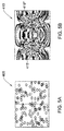
- FIGS. 5A and 5C are sample illustrations of (random) locations of a plurality of antennas, according to an embodiment of the present invention.
- FIGS. 5B and 5D are constructive interference maps of signals transmitted from a plurality of antennas, according to an embodiment of the present invention.
- FIG. 1 is a schematic illustration of a digital retro-directive system 100 for receiving signals from one or more transmitting sources, such as a source 150 and transmitting signals back towards said source 150 from a plurality of antennas in a substantially simultaneous (synchronous) manner and in a substantially precise angular direction, according to an embodiment of the present invention.
- system 100 is a multi-channel system, comprising a plurality of antennas (such as two or more antennas 105 ′, 105 ′′ and 105 ′′′, for example), wherein each antenna is connected to its corresponding communication unit 110 .
- Communication unit 110 comprises a receiver 115 for receiving an incoming signal (such as an RF signal, an electromagnetic signal, an acoustic signal, a seismic signal, a photonic signal, etc.); an A/D (Analog-to-Digital) unit 117 for sampling the received signal, giving rise to signal samples; a digital memory unit, such as a DRFM (Digital Radio Frequency Memory) unit 125 for storing the signal samples in its memory to be reconstructed later; a digital retro-processing unit 118 for reconstructing a signal from signal samples stored within DRFM unit 125 , said samples used as carriers for data to be transmitted, giving rise to a reconstructed digital signal; an D/A (Digital-to-Analog) unit 119 for converting said reconstructed digital signal to a reconstructed analog signal; and a transmitter 116 for transmitting the reconstructed analog signal back towards source 150 .
- the signals are considered to be RF signals; however, it should be noted that the signals can be of any combination
- the RF signal transmitted from transmitting source 150 (such as, a wireless or RF device/system (e.g., a cellular system, a Wi-Fi system, a radar system, etc.), a satellite device/system, an acoustic device/system, a seismic device/system, and the like) is received by means of antennas 105 ′, 105 ′′ and 105 ′. Then, the received signal is sampled by means of corresponding unit, such as A/D unit 117 . It should be noted that samples are performed substantially simultaneously by means of A/D units 117 of said antennas 105 ′, 105 ′′ and 105 ′′′.
- a wireless or RF device/system e.g., a cellular system, a Wi-Fi system, a radar system, etc.
- satellite device/system e.g., a satellite device/system, an acoustic device/system, a seismic device/system, and the like
- the received signal is sampled by means of corresponding
- each sample is made by means of each A/D unit 117 .
- the signal samples (a set of signal samples) ⁇ R,n (0) and ⁇ R,n (0.1) are stored in the sampling order, on a time scale, within corresponding DRFM units 125 , and then such samples can be used as carriers for data to be transmitted back towards transmitting source 150 .
- Said samples contain information regarding amplitude A R and reception phase ⁇ R,n of the signal received from said source 150 at each antenna 105 ′, 105 ′′ and 105 ′′′.
- the incoming signal can be sampled, for example, during 1 [ ⁇ sec](microseconds), while each sample can be taken each 0.1 [nsec]. It should be noted that since all samples are performed substantially simultaneously by means of A/D units 117 of said antennas 105 ′, 105 ′′ and 105 ′′′, then the set of signal samples, stored within each DRFM unit 125 , is substantially identical.
- the signal samples are reordered in an inverse sampling order by means of processing unit 118 , such that the first sample becomes the last one, for a predefined period of time (e.g., for 1 microsecond), resulting in the time-reversal of the signal.
- a new RF (digital) signal is reconstructed by using such inverted samples as data carriers, and then it is converted to an analog signal by means of each corresponding unit, such as D/A (Digital/Analog) unit 119 of each antenna 105 ′, 105 ′′ and 105 ′′′. After this, it is transmitted back towards source 150 .
- the signal is transmitted towards source 150 without measuring an angular direction of said source 150 , and without calculating the phase differences of the signal to be transmitted from each antenna within a predefined set (array) of antennas, such as antennas 105 ′, 105 ′′ and 105 ′′′ (it should be noted that according to the prior art, the signal phase differences for each antenna have to be calculated for achieving the optimal effective radiation pattern (ERP) in a desired angular direction).
- ERP effective radiation pattern
- the samples of antenna n are reordered such that the first sample is R n4 , the second is R n3 , the third is R n2 and the fourth sample is R n1 .
- each antenna 105 ′, 105 ′′, and 105 ′′′ is an antenna element within a set of mutually synchronized antenna elements, such as shown on FIG. 3A .
- each antenna 105 ′, 105 ′′, and/or 105 ′′′ comprises two or more mutually synchronized antenna elements, wherein each antenna element can have a communication unit, such as unit 110 .
- the modulation of the transmitted (outgoing) signal ⁇ T,n (t) (compared to the modulation of the received (incoming) signal ⁇ R,n (t)) is also inverted.
- transmitting source 150 is configured to transmit incoming RF signals and receive back outgoing RF signals, reconstructed from samples of said incoming RF signals, wherein for reconstructing the outgoing RF signals the samples are organized in an inverted sampling order, on a time scale.
- Transmitting source 150 receives said outgoing RF signals from at least one antenna, demodulates them and processes the demodulated data.
- transmitting source 150 is configured to determine that these RF signals have inverted modulation.
- transmitting source 150 can be provided with corresponding software and/or hardware processing means.
- ⁇ n, ⁇ R,n + ⁇ T,n const, wherein const is any constant (e.g., 0, 10, ⁇ 10, etc.) substantially identical for all antenna elements, and ⁇ T,n is the phase of the signal to be transmitted from antenna n.
- each reconstructed RF signal is transmitted back towards source 150 from each corresponding antenna 105 ′, 105 ′′ and 105 ′ in a substantially precise angular direction.
- each reconstructed RF signal is transmitted back towards source 150 by means of the same antenna (e.g., antenna 105 ′, 105 ′′ or 105 ′′′), through which the original corresponding signal from source 150 was received. Further, it should be noted that according to an embodiment of the present invention, the reconstructed RF signals are transmitted back towards source 150 in a substantially simultaneous (synchronous) manner from each antenna within a set of antennas (e.g., the set of antennas comprising two or more antennas, such as antennas 105 ′, 105 ′′ and 105 ′′′).
- the multi-pass communication with two or more transmitting sources 150 is enabled, without the need in determining phases of the signals to be transmitted back towards said sources from a plurality of antennas 105 ′, 105 ′′ and/or 105 ′′′ (without the need in determining angular directions of said two or more transmitting sources), and without the need in positioning the plurality antennas on a straight plane.
- said two or more transmitting sources 150 can be either far-distanced and/or located in proximity (near-field) to said plurality of antennas 105 ′, 105 ′′ and/or 105 ′. It should be noted that each source can transmit/receive a different RF signal.
- antennas 105 ′, 105 ′′ and/or 105 ′′′ are not synchronized with transmitting source 150 , i.e., are asynchronous to said source 150 either at the time and/or frequency domain.
- system 100 can be used in various applications, such as medical, military, space applications and the like. For example, by placing a set (plurality) of antennas around a human body, positioning a transmitting source (transmitter) within a cancerous growth inside the body, then receiving a signal from said transmitter, and after this transmitting a signal back to said source from the plurality of antennas in a substantially synchronous manner, can destroy such a cancerous growth at its exact location, and not accidentally damage other organs within the body.
- a transmitting source transmitter
- signal sampling is performed substantially synchronously by means of A/D units 117 of each antenna 105 ′, 105 ′′ and 105 ′′′.
- ⁇ n, ⁇ R,n + ⁇ T,n const, wherein const is any constant (e.g., 0, 10, ⁇ 10, etc.) substantially identical for all antenna elements.
- Signal ⁇ T,n (t) is transmitted towards source 150 without measuring an angular direction of said source 150 , and without calculating the phase differences of the signal to be transmitted from each antenna (it should be noted that according to the prior art, the signal phase differences for each antenna have to be calculated in order to achieve an effective radiation pattern in a desired angular direction). As a result, there is also no need in positioning antennas 105 ′, 105 ′′ and 105 ′′′ on a straight plane because there is no need in determining the above signal phase differences.
- the phase conjugation used for transmitting signals back towards transmitting source 150 may be applied to each frequency component of a wideband signal:
- i is an index varied from 1 to L.
- phase conjugation is mathematically equivalent to the time reversal (of the cyclic continuation of the signal to be conjugated); this arises due to phase anti-symmetry of the Fast Fourier Transform.
- other spectral decomposition analyses or other transforms can be implemented instead of the Fast Fourier Transform and Inverse Fast Fourier Transform.
- const is any constant (e.g., 0, 10, ⁇ 10, etc.)
- ⁇ T,n is the phase of the signal to be transmitted
- ⁇ R,n is the phase of the received signal
- this may be applied to each frequency component of a wideband signal:
- ⁇ is a constant; and i is an index.
- the constructive interference at transmitting source 150 is independent of the bandwidth and modulation of the transmitted signal. Also, an assumption that transmitting source 150 is far-distanced to allow linear phase front, is not required.
- a constructive interference may be achieved by assigning any real value to parameter ⁇ , wherein ⁇ .
- the location of transmitting source 150 , and/or antennas 105 ′, 105 ′′, 105 ′′′, etc., and/or any component/unit of communication unit 110 can be either static or mobile: for example, they can be airborne, sailed by a ship or carried by a vehicle, person, and the like. Also, it should be noted that if said transmitting source 150 and/or antennas 105 ′, 105 ′′, 105 ′′′ are dynamically relocated, then an appropriate compensation for such relocation can be applied.
- the reconstructed digital signal is transmitted back towards transmitting source 150 by means of, for example, two or more antennas 105 ′, 105 ′′, 105 ′′′ with a delay (e.g., a second, a minute, an hour, and the like).
- a delay e.g., a second, a minute, an hour, and the like.
- digital retro-processing unit 118 is incorporated within transmitter 116 .
- transmitting source 150 may also receive signals transmitted towards it, and process the received signals accordingly.
- FIGS. 2A to 2D are schematic illustrations of digital retro-processing unit 118 , according to an embodiment of the present invention.
- T seconds of samples of received signal ⁇ n,i R (t) the following signal is obtained at each antenna (e.g., by ignoring the communication channel noise):
- the constructive interference is achieved by reordering the recorded signal samples from the end to beginning, such that the signal to be transmitted is:
- each reconstructed RF signal is transmitted back towards source 150 ( FIG. 1 ) from each corresponding antenna 105 ′, 105 ′′ and 105 ′′′ ( FIG. 1 ) in a substantially precise angular direction.
- the modulation of the transmitted (outgoing) signal ⁇ T,n (t) (compared to the modulation of the received (incoming) signal ⁇ R,n (t)) is also inverted.
- the modulation of the received signal is linear
- the modulation of the transmitted signal is linear but inverted in time (time reversal).
- the received signal is characterized by having frequencies raising from the lower to higher frequency
- inverting an order of the signal samples results in obtaining a signal, in which frequencies are changed from the higher to lower frequency.
- transmitting source 150 is configured to transmit incoming RF signals and receive back outgoing RF signals, reconstructed from samples of said incoming RF signals, wherein for reconstructing the outgoing RF signals the samples are organized in an inverted sampling order, on a time scale. Transmitting source 150 receives said outgoing RF signals from at least one antenna, demodulates them and processes the demodulated data. According to another embodiment of the present invention, for demodulating said outgoing RF signals, transmitting source 150 is configured to determine that these RF signals have inverted modulation. For this, transmitting source 150 can be provided with corresponding software and/or hardware processing means.
- digital retro-processing unit 118 further comprises modulation unit 122 , as shown on FIG. 2B for modulating the signal with the inverted order of its samples. For this, time dependency t is added to the constant ⁇ . This leads to modulating the signal from transmitting source 150 , using the received signal as data carrier.
- digital retro-processing unit 118 comprises phase conjugation unit 123 and, optionally, modulation unit 122 , as presented on FIG. 2C .
- a sign of the phase of each received signal is inverted by means of processing unit 118 , resulting in obtaining phase conjugation of the signal. This can be done, for example, by digitally multiplying each sample by a function/signal, such as cosine(2 wt), and then digitally low-pass filtering the result. Then, the phase conjugated samples (having inverted phase signs) are stored within DRFM unit 125 ( FIG.
- the signal samples can be used later as carriers for transmitting data back towards source 150 ( FIG. 1 ).
- phase conjugation for example, for narrowband signals
- the phase conjugated signal to be transmitted is modulated by means of modulation unit 122 . For this, time dependency t is added to the constant ⁇ .
- phase conjugated signal to be transmitted can be modulated by its amplitude and phase by means of using parameters ⁇ (t) and ⁇ (t), respectively.
- digital retro-processing unit 118 comprises FFT (Fast Fourier Transform) unit 124 , phase conjugation unit 123 , IFFT (Inverse FFT) unit 126 and, optionally, modulation unit 122 , as presented on FIG. 2D .
- FFT Fast Fourier Transform
- phase conjugation unit 123 phase conjugation unit 123
- IFFT Inverse FFT
- modulation unit 122 modulation unit 122 , as presented on FIG. 2D .
- ⁇ T,n (1: N ) IFFT(conj(FFT( ⁇ R,n (1: N )))), wherein FFT is a Fast Fourier Transform, spectrally decompositing the signal to its frequency components; IFFT is an Inverse FFT; conj relates to obtaining a complex conjugate of a result of the FFT; and N is the number of samples to be retro-transmitted.
- FFT Fast Fourier Transform
- IFFT an Inverse FFT
- conj relates to obtaining a complex conjugate of a result of the FFT
- N is the number of samples to be retro-transmitted.
- phase conjugated signal to be transmitted is modulated by means of modulation unit 122 .
- ⁇ (t) is the amplitude modulation of transmitted signal
- L is the number of simultaneously received narrowband signals.
- the phase conjugated signal to be transmitted can be modulated by its amplitude or phase by means of using parameters ⁇ (t) and ⁇ (t).
- the modulated wideband signal ⁇ T,n (t) may be retro-transmitted, when required.
- w _ 2 ⁇ ⁇ ⁇ ( [ 0 : ( N / 2 - 1 ) , N / 2 , ( - N / 2 + 1 ) : - 1 ] ) ⁇ f s N (f s is a sampling frequency and N the FFT length).
- FIG. 3A is a schematic illustration of a digital retro-directive system 200 for receiving signals from one or more transmitting sources, such as a source 150 and transmitting signals back towards said source 150 in a substantially simultaneous manner and in a substantially precise angular direction, according to another embodiment of the present invention.
- a corner reflector 106 ′ is provided, being connected to a plurality of antennas (such as two or more antenna elements 105 ′, 105 ′′, 105 ′′′, for example) by means of its intersecting substantially flat surfaces 107 , 108 and/or 109 .
- each antenna 105 ′, 105 ′′ and 105 ′′ can be positioned on (connected to) the one or more intersecting flat surfaces (e.g., flat surface 109 ) of the corner reflector, and the antennas can be distanced one from another at a distance of, for example, a half wavelength ⁇ /2 of the highest radio frequency to be used for the signal transmission.
- each antenna is connected to its corresponding communication units 110 ( FIG. 1 ) that comprises a receiver 115 ( FIG. 1 ) for receiving an incoming RF signal; an A/D (Analog-to-Digital) unit 117 ( FIG.
- a digital memory unit such as a DRFM (Digital Radio Frequency Memory) unit 125 ( FIG. 1 ) for storing the signal samples in its memory to be reconstructed later; a digital retro-processing unit 118 ( FIG. 1 ) for reconstructing a RF signal from signal samples stored within DRFM unit 125 ( FIG. 1 ), said samples used as carriers for data to be transmitted, giving rise to a reconstructed digital RF signal; a D/A (Digital-to-Analog) unit 119 for converting said reconstructed digital RF signal to a reconstructed analog RF signal; and a transmitter 116 ( FIG. 1 ) for transmitting the reconstructed analog RF signal back towards source 150 .
- DRFM Digital Radio Frequency Memory
- the incoming RF signal from transmitting source 150 hits corner reflector 106 ′, and then it is detected by means of the set of antennas attached to the surface (such as antennas 105 ′, 105 ′′ and 105 ′′′).
- the RF signal is sampled by means of a corresponding unit, such as A/D unit 117 of each antenna, and then the signal samples are stored within corresponding DRFM units 125 of each antenna, for later usage. It should be noted that since all samples (resulting in a set of samples) are performed substantially simultaneously (synchronously) by means of A/D units 117 of said antennas, and then the set of signal samples, stored within each DRFM unit 125 , is substantially identical.
- RF signals are reconstructed from the stored signal samples (by means of processing unit 118 of each antenna).
- Each reconstructed RF digital signal is converted back to an analog signal by means of a corresponding unit, such as Digital-to-Analog (D/A) unit 119 .
- D/A Digital-to-Analog
- the analog signal is transmitted by means of transmitter 116 of each corresponding antenna within set of antennas, and when the reconstructed RF signal hits the corner reflector, it is reflected back towards source 150 .
- each DRFM unit 125 since the set of signal samples, stored within each DRFM unit 125 , is substantially identical (because all samples are performed substantially simultaneously by means of A/D units 117 of said antennas 105 ′, 105 ′′ and 105 ′′′), then performing D/A conversion by means of D/A units 119 of said antennas 105 ′, 105 ′′ and 105 ′′′ is also done substantially simultaneously at each antenna. As a result, the signal after the D/A conversion is transmitted back towards source 150 substantially simultaneously from each antenna.
- Constant C defines an arbitrary phase delay, applied substantially identically to all antennas within the set.
- antenna elements 105 ′, 105 ′′, 105 ′′′ are mutually synchronized for enabling transmitting the reconstructed RF signal back towards transmitting source 150 in a substantially precise angular direction.
- modulation of the transmitted signal ⁇ T,n (t) remains the same as the modulation of the received signal ⁇ R,n (t).
- signal ⁇ T,n (t) is transmitted towards source 150 (by being reflected from corresponding corner reflector) without measuring an angular direction of said source 150 , and without calculating the phase differences of the signal to be transmitted from each antenna 105 ′, 105 ′′ and 105 ′′′ (that is required, according to the prior art, for getting the greatest overall ERP in the direction, to which the RF signal is transmitted).
- phase differences that is required, according to the prior art, for getting the greatest overall ERP in the direction, to which the RF signal is transmitted.
- FIG. 3B is a schematic illustration of digital retro-processing unit 118 to be provided for each antenna 105 ′, 105 ′′ of 105 ′′′ ( FIG. 3A ) located on corner reflector 106 ′, according to another embodiment of the present invention.
- the signal to be transmitted is modulated by means of modulation unit 122 .
- ⁇ T,n (t) a modulated transmitted wideband signal
- the phase conjugated signal to be transmitted can be modulated by its amplitude or phase by means of using parameters ⁇ (t) and ⁇ (t).
- the modulated wideband signal ⁇ T,n (t) may be retro-transmitted, when required.
- w _ 2 ⁇ ⁇ ⁇ ( [ 0 : ( N / 2 - 1 ) , N / 2 , ( - N / 2 + 1 ) : - 1 ] ) ⁇ f s N (f s is a sampling frequency and N the FFT length).
- FIG. 4A is a flow chart of a retro-directive method for transmitting signals back towards transmitting source 150 ( FIG. 1 ) in a substantially synchronous manner and in a substantially precise angular direction, according to an embodiment of the present invention.
- the incoming RF signal is received by means of antennas 105 ′, 105 ′′ and 105 ′′′ ( FIG. 1 ).
- the signal is sampled by means of A/D unit 117 ( FIG. 1 ) provided within communication unit 110 ( FIG. 1 ) of each antenna.
- each signal sample is stored within corresponding DRFM units 125 ( FIG. 1 ) of each antenna.
- an order of the signal samples is inverted, such that for a predefined period of time (e.g., 1 microsecond), the first sample becomes the last one.
- a new signal is reconstructed by using said inverted signal samples as carriers for data to be transmitted, giving rise to a reconstructed digital RF signal.
- said reconstructed digital RF signal is converted by means of D/A unit 119 ( FIG. 1 ) into a reconstructed analog RF signal, which is transmitted back towards source 150 by means of transmitter 116 , at step 335 .
- the first sample of a signal received by antenna 105 ′ is R 11
- the second is R 12
- the third is R 13
- the fourth sample is R 14
- by reordering said samples in an inverse order, such that the first sample is R 14 , the second is R 13 , the third is R 12 and the fourth sample is R 11 , and then using said samples as carriers for the data to be transmitted enables transmitting said signal back towards source 150 in a substantially precise angular direction.
- FIG. 4B is a flow chart of a retro-directive method for transmitting signals back towards transmitting source 150 ( FIG. 1 ) in a substantially synchronous manner and in a substantially precise angular direction, according to another embodiment of the present invention.
- the incoming RF signal is received by means of each antenna 105 ′, 105 ′′ and 105 ′′′ ( FIG. 1 ).
- the signal is sampled by means of A/D unit 117 ( FIG. 1 ) provided within communication unit 110 ( FIG. 1 ) of each antenna.
- the amplitude of each signal sample is stored within corresponding DRFM unit 125 ( FIG. 1 ) of each antenna.
- a sign of the initial phase of each signal is inverted (for example, by means of multiplying each signal by a function/signal, such as cosine(2wt) for narrowband signal, or by using FFT for wideband signals. This results in obtaining phase conjugated signals.
- a new signal is reconstructed by using said samples that have been phase conjugated as carriers of data to be transmitted, giving rise to a reconstructed digital RF signal.
- said reconstructed digital RF signal is converted by means of D/A unit 119 ( FIG. 1 ) into a reconstructed analog RF signal, which is transmitted back towards source 150 by means of transmitter 116 ( FIG. 1 ), at step 370 .
- each reconstructed RF signal is transmitted back towards source 150 by means of the same antenna (e.g., antenna 105 ′, 105 ′′ or 105 ′′′), through which the original corresponding signal from source 150 was received.
- the same antenna e.g., antenna 105 ′, 105 ′′ or 105 ′′′
- FIG. 4C is a flow chart of a retro-directive method for transmitting signals back towards source 150 ( FIG. 1 ) in a substantially synchronous manner and in a substantially precise angular direction, according to still another embodiment of the present invention.
- a set of antennas such as antennas 105 ′, 105 ′′ and 105 ′′′ ( FIG. 3A ), is connected to corner reflector 106 ′ ( FIG. 3A ).
- the antennas can be positioned on one or more intersecting flat surfaces of the corner reflector, and the antennas can be distanced one from another at the distance of, for example, a half wavelength of the highest radio frequency to be used for the signal transmission.
- each antenna is connected to its corresponding communication units 110 ( FIG. 1 ).
- the RF signal from transmitting source 150 hits a corner reflector 106 ′, and then it is received by a set of antennas 105 ′, 105 ′′, 105 ′′′. Then, at step 375 , the signal is sampled by means of A/D unit 117 ( FIG. 1 ) provided within communication unit 110 of each antenna within said set. After this, at step 380 , each signal sample is stored within corresponding DRFM units 125 ( FIG. 1 ) of each antenna. At step 385 , a new RF signal is reconstructed from said data samples, which are used as carriers for the data to be transmitted, giving rise to a reconstructed digital RF signal.
- said reconstructed digital RF signal is converted by means of D/A unit 119 ( FIG. 1 ) into a reconstructed analog RF signal, which is (at step 395 ) transmitted by means of transmitter 116 ( FIG. 1 ) of each antenna within set of antennas, and when the reconstructed RF signal hits corner reflector 106 ′, it is reflected back towards source 150 .
- the transmitted RF signal goes in substantially precise angular direction back towards source 150 .
- modulation of the transmitted signal ⁇ T,n (t) remains the same as the modulation of the received signal ⁇ R,n (t).
- FIGS. 5A and 5C are sample illustrations of (random) locations of a plurality of antennas 405 , 406
- FIGS. 5B and 5D are constructive interference maps 410 , 411 of signals transmitted from said plurality of antennas, respectively, according to an embodiment of the present invention.
- Illustrations 405 and 406 present a plurality of randomly positioned antennas, wherein each antenna is represented by a circle.
- Illustration 410 presents a constructive interference map of signals transmitted from said plurality of antennas 405 back towards transmitting source 150 ( FIG. 1 ), which is represented by point 415 ′ (or 415 ′′) on the graph.
- the signals are transmitted towards source 415 ′ (or 415 ′′) from the plurality of antennas 405 without measuring an angular direction of said source and without calculating the phase differences of the signal transmitted from each antenna.
- source 415 ′ or 415 ′′
- the signals are transmitted towards source 415 ′ (or 415 ′′) from the plurality of antennas 405 without measuring an angular direction of said source and without calculating the phase differences of the signal transmitted from each antenna.
- illustration 411 is a constructive interference map of signals transmitted from a plurality of antennas 406 back towards two transmitting sources, the first source represented by points 416 ′ (or 416 ′′) and the second source represented by curve 420 .
- This illustration 411 relates to communication with two or more transmitting sources.
- illustration 410 there is no need in measuring an angular direction of said sources, and there is no need in calculating the phase differences of the RF signal to be transmitted from each antenna. Further, it is not necessary to position a plurality of antennas 406 on a straight plane.
Abstract
Description
-
- a) at least two antennas; and
- b) at least two communication units, each of which is connected to its corresponding antenna, said each communication unit comprising:
- b.1. a receiver for receiving a signal from a transmitting source;
- b.2. an Analog-to-Digital (A/D) unit for sampling the received signal for a predefined period of time, giving rise to signal samples;
- b.3. a digital memory unit for storing the signal samples of said received signal in its memory in a given sampling order, on a time scale;
- b.4. a processing unit for reconstructing a signal, including:
- b.4.1. deciding about at least one sub-group of signal samples that are sampled within said predefined period of time;
- b.4.2. inverting said sampling order of said signal samples within said at least one sub-group; and
- b.4.3. reconstructing said signal by using said signal samples, which have the inverted sampling order, as data carriers, giving rise to a reconstructed digital signal;
- b.5. a Digital-to-Analog (D/A) unit for converting said reconstructed digital signal to a reconstructed analog signal to be transmitted; and
- b.6. a transmitter for transmitting said reconstructed analog signal back towards said transmitting source substantially simultaneously from each of said at least two antennas.
-
- a) a Radio Frequency (RF) signal;
- b) an electromagnetic (EM) signal;
- c) an acoustic signal;
- d) a seismic signal; and
- e) a photonic signal.
-
- a) at least two antennas; and
- b) at least two communication units, each of which is connected to its corresponding antenna, said each communication unit comprising:
- b.1. a receiver for receiving a signal from a transmitting source;
- b.2. an A/D unit for sampling the received signal for a predefined period of time, giving rise to signal samples, each of which has an amplitude and phase;
- b.3. a digital memory unit for storing the signal samples of said received signal in its memory in a given sampling order, on a time scale;
- b.4. a processing unit for reconstructing a signal, including:
- b.4.1. deciding about at least one sub-group of signal samples that are sampled within said predefined period of time;
- b.4.2 performing phase conjugation of each signal sample within said at least one sub-group, giving rise to phase conjugated signal samples; and
- b.4.3. reconstructing said signal by using said phase conjugated signal samples as data carriers, giving rise to a reconstructed digital signal;
- b.5. a D/A unit for converting said reconstructed digital signal to a reconstructed analog signal to be transmitted; and
- b.6. a transmitter for transmitting said reconstructed analog signal back towards said transmitting source substantially simultaneously from each of said at least two antennas.
-
- a) a corner reflector; and
- b) at least two antennas connected to said corner reflector, each of said at least two antennas further connected to its corresponding communication unit that comprises:
- b.1. a receiver for receiving a signal from a transmitting source;
- b.2. an A/D unit for sampling the received signal for a predefined period of time, giving rise to signal samples;
- b.3. a digital memory unit for storing the signal samples of said received signal in its memory in a given sampling order, on a time scale;
- b.4. a processing unit for reconstructing a signal by using said signal samples as data carriers, giving rise to a reconstructed digital signal;
- b.5. a D/A unit for converting said reconstructed digital signal to a reconstructed analog signal to be transmitted; and
- b.6. a transmitter for transmitting said reconstructed analog signal to be reflected from said corner reflector back towards said transmitting source substantially simultaneously from each of said at least two antennas.
-
- a) deciding about at least one sub-group of signal samples that are sampled within the predefined period of time;
- b) inverting said sampling order of said signal samples within said at least one sub-group; and
- c) reconstructing said signal by using said signal samples, which have the inverted sampling order, as data carriers.
-
- a) deciding about at least one sub-group of signal samples that are sampled within the predefined period of time;
- b) performing phase conjugation of the signal samples within said at least one sub-group, giving rise to phase conjugated signal samples; and
- c) reconstructing said signal by using said phase conjugated signal samples as data carriers.
-
- a) receiving a signal from a transmitting source;
- b) sampling the received signal for a predefined period of time, giving rise to signal samples;
- c) storing the signal samples in a given sampling order, on a time scale;
- d) reconstructing a signal, including:
- d.1 deciding about at least one sub-group of signal samples that are sampled within said predefined period of time;
- d.2. inverting said sampling order of said signal samples within said at least one sub-group; and
- d.3. reconstructing said signal by using said signal samples, which have the inverted sampling order, as data carriers, giving rise to a reconstructed digital signal;
- e) converting said reconstructed digital signal to a reconstructed analog signal; and
- f) transmitting said reconstructed analog signal back towards said transmitting source.
-
- a) receiving a signal from a transmitting source;
- b) sampling the received signal for a predefined period of time, giving rise to signal samples;
- c) storing the signal samples in a given sampling order, at the time scale;
- d) reconstructing a signal, including:
- d.1. deciding about at least one sub-group of signal samples that are sampled within said predefined period of time;
- d.2. performing phase conjugation of signal samples within said at least one sub-group, giving rise to phase conjugated signal samples; and
- d.3. reconstructing said signal by using said signal samples, which have been phase conjugated, as data carriers, giving rise to a reconstructed digital signal;
- e) converting said reconstructed digital signal to a reconstructed analog signal; and
- f) transmitting said reconstructed analog signal back towards said transmitting source.
-
- a) providing a corner reflector, connected to at least two antennas;
- b) receiving an incoming signal from a transmitting source by means of said at least two antennas;
- c) sampling the received signal for a predefined period of time, giving rise to signal samples;
- d) storing the signal samples in a given sampling order, at the time scale;
- e) reconstructing a signal by using the signal samples as data carriers, giving rise to a reconstructed digital signal;
- f) converting said reconstructed digital signal to a reconstructed analog signal; and
- g) transmitting said reconstructed analog signal to be reflected from said corner reflector back towards said transmitting source substantially simultaneously from each of said at least two antennas.
φR,n(0)=A R·cos(w·0+φR)=A R·cos(φR) and φR,n(0.1)=A R·cos(w·0.1+φR).
φT,n(t)=A cos(φt+φ T,n)=A cos(ωt+(const−φR,n))=A cos(ωt−ωT′−φ R,n)=A cos(ωT′−ωt+φ R,n)=φR,n(T′−t),
wherein φT,n is a phase of the transmitted signal, T′ relates to a predefined period of time (e.g., 1 microsecond), T symbolizes that the signal is transmitted, and const is selected as: −ωT′ (w is a radian frequency). From the above it follows that if the signal is transmitted from its end to the beginning (on a time scale, by inverting an order of signal samples, used as data carriers), a constructive interference in a direction from which the signal was received is achieved. As a result, each reconstructed RF signal is transmitted back towards
wherein φR,n(t) is a received signal, φT,n(t) is a transmitted signal, AR,i and AT,i are amplitudes, wi is a radian frequency, t is a time parameter, φi R,n and are φi T,n are phases of corresponding received and transmitted signals, n is an antenna serial number (e.g., 1, 2, . . . ), and i is an index varied from 1 to L. This may be achieved by performing spectral decomposition of said wideband signal and performing phase conjugation of each component, such that:
φT,n(1:N)=IFFT(conj(FFT(φR,n(1:N)))),
wherein FFT is a Fast Fourier Transform, spectrally decompositing the signal to its frequency components; IFFT is an Inverse FFT; conj relates to obtaining a complex conjugate of a result of the FFT; and N is the number of samples to be retro-transmitted, i.e., N is the FFT length.
wherein
φi T,n+φi R,n =C i =α·w i
and hence ∀i,
α is a constant; and i is an index. The definition of the constants Ci ensures that the time delays are identical for all frequency components from i=1 to i=L. As a result, the constructive interference of all frequency components may be obtained by assigning any parameters αε
wherein A is an amplitude of the signal; w is a radian frequency; t is a time parameter; φn,i R is a phase of the ith spectral component of received signal φn,i R(t); n is an antenna serial number (e.g., 1, 2, . . . ); i is a signal index; and the letter R symbolizes that the signal is received.
φT,n(t)=β(t)·φR,n(T−t),
wherein β(t) represents the amplitude modulation (AM).
∀n φn T+φn R =C(t)=α(t)·w
wherein φn T is a phase of the transmitted signal; and φn R is a phase of the received signal. As a result, modulated transmitted signal φT,n(t) can be as follows:
φT,n(t)=β(t)·A cos(w(t+α(t))−φn R),
wherein β(t) represents the amplitude modulation.
φT,n(1:N)=IFFT(conj(FFT(φR,n(1:N)))),
wherein FFT is a Fast Fourier Transform, spectrally decompositing the signal to its frequency components; IFFT is an Inverse FFT; conj relates to obtaining a complex conjugate of a result of the FFT; and N is the number of samples to be retro-transmitted. It should be noted that phases φn R are obtained by means of the Fourier analysis, the phase conjugation ensures that φn T=−φn R, and the inverse transform (IFFT) yields the phase conjugated signal. Further, the phase conjugated signal to be transmitted is modulated by means of
∀n,i φ n,i T+φn,i R =C i(t)=α(t)·w i,
wherein φn,i T is a phase of the transmitted signal; and φn,i R is a phase of the received signal. As a result, a modulated wideband transmitted signal φT,n(t) can be as follows:
wherein β(t) is the amplitude modulation of transmitted signal; and L is the number of simultaneously received narrowband signals. It should be noted that the phase conjugated signal to be transmitted can be modulated by its amplitude or phase by means of using parameters β(t) and α(t). Then, the modulated wideband signal φT,n(t) may be retro-transmitted, when required. This can be achieved by the following operation on the recorded (stored) samples:
φT,n(1:N)=β(t)·IFFT(e iα(t)·
wherein
(fs is a sampling frequency and N the FFT length).
∀n Δφ n=φn T−φn R=Const=C
∀n,i φ n,i T−φn,i R =C i(t)=α(t)·w i,
wherein φn,i T is a phase of the transmitted signal; and φn,i R is a phase of the received signal. As a result, a modulated transmitted wideband signal φT,n(t) can be as follows:
wherein β(t) is the amplitude modulation of transmitted signal; and L is a number of simultaneously received narrowband signals. It should be noted that the phase conjugated signal to be transmitted can be modulated by its amplitude or phase by means of using parameters β(t) and α(t). Then, the modulated wideband signal φT,n(t) may be retro-transmitted, when required. The modulation can be implemented as follows:
φT,n(1:N)=β(t)·IFFT(e iα(t)·
wherein
(fs is a sampling frequency and N the FFT length).
Claims (13)
Applications Claiming Priority (3)
| Application Number | Priority Date | Filing Date | Title |
|---|---|---|---|
| IL196146A IL196146A (en) | 2008-12-23 | 2008-12-23 | System and method of transmitting a signal back towards a transmitting source |
| IL196146 | 2008-12-23 | ||
| PCT/IL2009/001166 WO2010073241A2 (en) | 2008-12-23 | 2009-12-09 | Digital retro-directive communication system and method thereof |
Related Parent Applications (1)
| Application Number | Title | Priority Date | Filing Date |
|---|---|---|---|
| PCT/IL2009/001166 A-371-Of-International WO2010073241A2 (en) | 2008-12-23 | 2009-12-09 | Digital retro-directive communication system and method thereof |
Related Child Applications (1)
| Application Number | Title | Priority Date | Filing Date |
|---|---|---|---|
| US14/574,694 Continuation US9143220B2 (en) | 2008-12-23 | 2014-12-18 | Digital retro-directive communication system and method thereof |
Publications (2)
| Publication Number | Publication Date |
|---|---|
| US20120106659A1 US20120106659A1 (en) | 2012-05-03 |
| US8948277B2 true US8948277B2 (en) | 2015-02-03 |
Family
ID=41820308
Family Applications (3)
| Application Number | Title | Priority Date | Filing Date |
|---|---|---|---|
| US13/141,928 Expired - Fee Related US8948277B2 (en) | 2008-12-23 | 2009-12-09 | Digital retro-directive communication system and method thereof |
| US14/574,694 Active US9143220B2 (en) | 2008-12-23 | 2014-12-18 | Digital retro-directive communication system and method thereof |
| US14/855,559 Active US9325403B2 (en) | 2008-12-23 | 2015-09-16 | Digital retro-directive communication system and method thereof |
Family Applications After (2)
| Application Number | Title | Priority Date | Filing Date |
|---|---|---|---|
| US14/574,694 Active US9143220B2 (en) | 2008-12-23 | 2014-12-18 | Digital retro-directive communication system and method thereof |
| US14/855,559 Active US9325403B2 (en) | 2008-12-23 | 2015-09-16 | Digital retro-directive communication system and method thereof |
Country Status (6)
| Country | Link |
|---|---|
| US (3) | US8948277B2 (en) |
| EP (2) | EP3190662A1 (en) |
| AU (1) | AU2009332516A1 (en) |
| IL (1) | IL196146A (en) |
| SG (1) | SG172372A1 (en) |
| WO (1) | WO2010073241A2 (en) |
Families Citing this family (16)
| Publication number | Priority date | Publication date | Assignee | Title |
|---|---|---|---|---|
| US20150241342A1 (en) * | 2014-02-25 | 2015-08-27 | California Institute Of Technology | Digital phase conjugation using moving target as guide star |
| US8466776B2 (en) * | 2010-07-01 | 2013-06-18 | The United States Of America As Represented By The Administrator Of The National Aeronautics And Space Administration | Extended range passive wireless tag system and method |
| US9275690B2 (en) | 2012-05-30 | 2016-03-01 | Tahoe Rf Semiconductor, Inc. | Power management in an electronic system through reducing energy usage of a battery and/or controlling an output power of an amplifier thereof |
| US9509351B2 (en) | 2012-07-27 | 2016-11-29 | Tahoe Rf Semiconductor, Inc. | Simultaneous accommodation of a low power signal and an interfering signal in a radio frequency (RF) receiver |
| IL221162A (en) | 2012-07-29 | 2017-06-29 | Elta Systems Ltd | Transponder device |
| US9780449B2 (en) | 2013-03-15 | 2017-10-03 | Integrated Device Technology, Inc. | Phase shift based improved reference input frequency signal injection into a coupled voltage controlled oscillator (VCO) array during local oscillator (LO) signal generation to reduce a phase-steering requirement during beamforming |
| US9531070B2 (en) | 2013-03-15 | 2016-12-27 | Christopher T. Schiller | Extending beamforming capability of a coupled voltage controlled oscillator (VCO) array during local oscillator (LO) signal generation through accommodating differential coupling between VCOs thereof |
| US9722310B2 (en) | 2013-03-15 | 2017-08-01 | Gigpeak, Inc. | Extending beamforming capability of a coupled voltage controlled oscillator (VCO) array during local oscillator (LO) signal generation through frequency multiplication |
| US9837714B2 (en) | 2013-03-15 | 2017-12-05 | Integrated Device Technology, Inc. | Extending beamforming capability of a coupled voltage controlled oscillator (VCO) array during local oscillator (LO) signal generation through a circular configuration thereof |
| US9716315B2 (en) | 2013-03-15 | 2017-07-25 | Gigpeak, Inc. | Automatic high-resolution adaptive beam-steering |
| US9184498B2 (en) | 2013-03-15 | 2015-11-10 | Gigoptix, Inc. | Extending beamforming capability of a coupled voltage controlled oscillator (VCO) array during local oscillator (LO) signal generation through fine control of a tunable frequency of a tank circuit of a VCO thereof |
| US9666942B2 (en) | 2013-03-15 | 2017-05-30 | Gigpeak, Inc. | Adaptive transmit array for beam-steering |
| US9548799B2 (en) * | 2013-04-07 | 2017-01-17 | Ziv A Corp. | Distributed co-operating nodes using time reversal |
| US9923647B1 (en) * | 2016-12-16 | 2018-03-20 | Litepoint Corporation | Method for enabling confirmation of expected phase shifts of radio frequency signals emitted from an antenna array |
| US10276411B2 (en) * | 2017-08-18 | 2019-04-30 | Applied Materials, Inc. | High pressure and high temperature anneal chamber |
| WO2021224952A1 (en) * | 2020-05-07 | 2021-11-11 | 合同会社パッチドコニックス | Communication system and signal processing method |
Citations (20)
| Publication number | Priority date | Publication date | Assignee | Title |
|---|---|---|---|---|
| US2908002A (en) | 1955-06-08 | 1959-10-06 | Hughes Aircraft Co | Electromagnetic reflector |
| US3833893A (en) | 1972-10-24 | 1974-09-03 | Rca Corp | Holographic memory including corner reflectors |
| US4080660A (en) | 1975-07-11 | 1978-03-21 | James Nickolas Constant | Digital signal time scale inversion |
| US4383332A (en) | 1980-11-21 | 1983-05-10 | Bell Telephone Laboratories, Incorporated | High capacity digital mobile radio system |
| US4762397A (en) | 1987-06-19 | 1988-08-09 | Hughes Aircraft Company | Optical phase conjugator with spatially resolvable thresholding utilizing liquid crystal light valve |
| US4908825A (en) * | 1988-04-08 | 1990-03-13 | Northern Telecom Limited | Memory organization and output sequencer for a signal processor |
| US5163176A (en) * | 1980-12-29 | 1992-11-10 | Raytheon Company | All weather tactical strike system (AWTSS) and method of operation |
| US5254997A (en) | 1992-07-31 | 1993-10-19 | Westinghouse Electric Corp. | Retrodirective interrogation responsive system |
| US5909299A (en) | 1997-04-28 | 1999-06-01 | Sheldon, Jr.; L. Philip | Microsatellite system for high-volume orbital telemetry |
| US6211815B1 (en) | 1997-07-25 | 2001-04-03 | Honeywell International Inc. | Coherent radar detection using non-coherent architecture |
| WO2002005436A2 (en) | 2000-07-11 | 2002-01-17 | Telecom Italia Lab S.P.A. | Method for transmitting signals in communication networks, associated system and terminal |
| US6630905B1 (en) | 2000-11-10 | 2003-10-07 | Raytheon Company | System and method for redirecting a signal using phase conjugation |
| US20040021613A1 (en) * | 2000-09-29 | 2004-02-05 | Aleksandar Nesic | Dipole feed arrangement for corner feflector antenna |
| US20040114772A1 (en) * | 2002-03-21 | 2004-06-17 | David Zlotnick | Method and system for transmitting and/or receiving audio signals with a desired direction |
| US20060098746A1 (en) | 2002-11-06 | 2006-05-11 | The Regents Of The University Of California | Multi-channel time-reversal receivers for multi and 1-bit implementations |
| US7081850B2 (en) | 2004-06-03 | 2006-07-25 | Raytheon Company | Coherent detection of ultra wideband waveforms |
| US7089796B2 (en) | 2004-03-24 | 2006-08-15 | Hrl Laboratories, Llc | Time-reversed photoacoustic system and uses thereof |
| US20070182635A1 (en) * | 2004-06-28 | 2007-08-09 | Ha Jae Jeung | Array antenna for suppressing back singal and method for designing the same |
| US20080266152A1 (en) | 2007-04-26 | 2008-10-30 | Roger Dean Durtschi | Digital radio frequency memory |
| US20100152600A1 (en) * | 2008-04-03 | 2010-06-17 | Kai Sensors, Inc. | Non-contact physiologic motion sensors and methods for use |
Family Cites Families (8)
| Publication number | Priority date | Publication date | Assignee | Title |
|---|---|---|---|---|
| US4131791A (en) | 1975-12-08 | 1978-12-26 | General Electric Company | Search and locate system |
| US4286283A (en) * | 1979-12-20 | 1981-08-25 | Rca Corporation | Transcoder |
| US20040209554A1 (en) | 2002-06-04 | 2004-10-21 | Akio Tsumagari | Polishing material and method of polishing therewith |
| AU2004225931A1 (en) | 2003-03-25 | 2004-10-14 | Neopad Technologies Corporation | Chip customized polish pads for chemical mechanical planarization (CMP) |
| US20050041746A1 (en) * | 2003-08-04 | 2005-02-24 | Lowell Rosen | Software-defined wideband holographic communications apparatus and methods |
| US7195544B2 (en) | 2004-03-23 | 2007-03-27 | Cabot Microelectronics Corporation | CMP porous pad with component-filled pores |
| JP4475404B2 (en) | 2004-10-14 | 2010-06-09 | Jsr株式会社 | Polishing pad |
| JP5289319B2 (en) * | 2006-10-20 | 2013-09-11 | フランス・テレコム | Method, program, and apparatus for generating concealment frame (packet) |
-
2008
- 2008-12-23 IL IL196146A patent/IL196146A/en active IP Right Grant
-
2009
- 2009-12-09 SG SG2011046471A patent/SG172372A1/en unknown
- 2009-12-09 EP EP17153705.3A patent/EP3190662A1/en active Pending
- 2009-12-09 EP EP09802219.7A patent/EP2377199B1/en active Active
- 2009-12-09 US US13/141,928 patent/US8948277B2/en not_active Expired - Fee Related
- 2009-12-09 AU AU2009332516A patent/AU2009332516A1/en not_active Abandoned
- 2009-12-09 WO PCT/IL2009/001166 patent/WO2010073241A2/en active Application Filing
-
2014
- 2014-12-18 US US14/574,694 patent/US9143220B2/en active Active
-
2015
- 2015-09-16 US US14/855,559 patent/US9325403B2/en active Active
Patent Citations (20)
| Publication number | Priority date | Publication date | Assignee | Title |
|---|---|---|---|---|
| US2908002A (en) | 1955-06-08 | 1959-10-06 | Hughes Aircraft Co | Electromagnetic reflector |
| US3833893A (en) | 1972-10-24 | 1974-09-03 | Rca Corp | Holographic memory including corner reflectors |
| US4080660A (en) | 1975-07-11 | 1978-03-21 | James Nickolas Constant | Digital signal time scale inversion |
| US4383332A (en) | 1980-11-21 | 1983-05-10 | Bell Telephone Laboratories, Incorporated | High capacity digital mobile radio system |
| US5163176A (en) * | 1980-12-29 | 1992-11-10 | Raytheon Company | All weather tactical strike system (AWTSS) and method of operation |
| US4762397A (en) | 1987-06-19 | 1988-08-09 | Hughes Aircraft Company | Optical phase conjugator with spatially resolvable thresholding utilizing liquid crystal light valve |
| US4908825A (en) * | 1988-04-08 | 1990-03-13 | Northern Telecom Limited | Memory organization and output sequencer for a signal processor |
| US5254997A (en) | 1992-07-31 | 1993-10-19 | Westinghouse Electric Corp. | Retrodirective interrogation responsive system |
| US5909299A (en) | 1997-04-28 | 1999-06-01 | Sheldon, Jr.; L. Philip | Microsatellite system for high-volume orbital telemetry |
| US6211815B1 (en) | 1997-07-25 | 2001-04-03 | Honeywell International Inc. | Coherent radar detection using non-coherent architecture |
| WO2002005436A2 (en) | 2000-07-11 | 2002-01-17 | Telecom Italia Lab S.P.A. | Method for transmitting signals in communication networks, associated system and terminal |
| US20040021613A1 (en) * | 2000-09-29 | 2004-02-05 | Aleksandar Nesic | Dipole feed arrangement for corner feflector antenna |
| US6630905B1 (en) | 2000-11-10 | 2003-10-07 | Raytheon Company | System and method for redirecting a signal using phase conjugation |
| US20040114772A1 (en) * | 2002-03-21 | 2004-06-17 | David Zlotnick | Method and system for transmitting and/or receiving audio signals with a desired direction |
| US20060098746A1 (en) | 2002-11-06 | 2006-05-11 | The Regents Of The University Of California | Multi-channel time-reversal receivers for multi and 1-bit implementations |
| US7089796B2 (en) | 2004-03-24 | 2006-08-15 | Hrl Laboratories, Llc | Time-reversed photoacoustic system and uses thereof |
| US7081850B2 (en) | 2004-06-03 | 2006-07-25 | Raytheon Company | Coherent detection of ultra wideband waveforms |
| US20070182635A1 (en) * | 2004-06-28 | 2007-08-09 | Ha Jae Jeung | Array antenna for suppressing back singal and method for designing the same |
| US20080266152A1 (en) | 2007-04-26 | 2008-10-30 | Roger Dean Durtschi | Digital radio frequency memory |
| US20100152600A1 (en) * | 2008-04-03 | 2010-06-17 | Kai Sensors, Inc. | Non-contact physiologic motion sensors and methods for use |
Non-Patent Citations (4)
| Title |
|---|
| Didomenico L D et al: "Digital Communications Using Self-Phased Arrays" IEEE Transactions on Microwave Theory and Techniques, IEEE Service Center, Piscataway, NJ, US, vol. 49, No. 4, Part 01, Apr. 1, 2001, pp. 677-684, XP001093384 ISSN: 0018-9480. |
| Gomes J et al: "Time-reversed OFDM communication in underwater channels" Signal Processing Advances in Wireless Communications, 2004 IEEE 5th Workshop on Lisbon, Portugal Jul. 11-14, 2004, Piscataway, NJ, USA, IEEE LINKD-DOI:10.1109/SPAWC.2004.1439321, Jul. 11, 2004, pp. 626-630, XP010805978 ISBN: 978-0-7803-8337-1. |
| Gomes J et al: "Wavefront segmentation in phase-conjugate arrays for spatially modulated acoustic communication" Oceans, 2001, MTS/IEEE Conference and Exhibition Nov. 5-8, 2001, Piscataway, NJ, USA, IEEE, vol. 4, Nov. 5, 2001, pp. 2236-2243, XP010566783 ISBN: 978-0-933957-28-2. |
| Loadman C et al.: "A retrodirective array using direct down-conversion and fixed point DSP for duplex digital communications" Radio and Wireless Symposium, 2006 IEEE San Diego, CA, USA 2006, Piscataway, NJ, USA, IEEE, Jan. 1, 2006, pp. 335-338, XP010906537 ISBN: 978-0-7803-9412-4 p. 335, paragraph 1-p. 337, paragraph 3; figures 1,2. |
Also Published As
| Publication number | Publication date |
|---|---|
| IL196146A0 (en) | 2009-12-24 |
| US20160020841A1 (en) | 2016-01-21 |
| US9325403B2 (en) | 2016-04-26 |
| IL196146A (en) | 2014-01-30 |
| US20120106659A1 (en) | 2012-05-03 |
| EP2377199B1 (en) | 2017-03-15 |
| SG172372A1 (en) | 2011-07-28 |
| WO2010073241A2 (en) | 2010-07-01 |
| WO2010073241A4 (en) | 2010-10-21 |
| EP3190662A1 (en) | 2017-07-12 |
| EP2377199A2 (en) | 2011-10-19 |
| AU2009332516A1 (en) | 2011-08-04 |
| US9143220B2 (en) | 2015-09-22 |
| WO2010073241A3 (en) | 2010-08-19 |
| US20150155927A1 (en) | 2015-06-04 |
Similar Documents
| Publication | Publication Date | Title |
|---|---|---|
| US9325403B2 (en) | Digital retro-directive communication system and method thereof | |
| US9070972B2 (en) | Wideband beam forming device; wideband beam steering device and corresponding methods | |
| Camps et al. | Optimization and performance analysis of interferometric GNSS-R altimeters: Application to the PARIS IoD mission | |
| EP0852017B1 (en) | Locating the source of an unknown signal | |
| US8009083B2 (en) | Detection and ranging apparatus and method of designing detection and ranging apparatus | |
| Babur et al. | Nearly orthogonal waveforms for MIMO FMCW radar | |
| JP5617334B2 (en) | Radar apparatus and target detection method | |
| US7333897B2 (en) | Method and system for identifying material composition based upon polarization trajectories | |
| Guan et al. | 3-D imaging using millimeter-wave 5G signal reflections | |
| Vouras et al. | An overview of advances in signal processing techniques for classical and quantum wideband synthetic apertures | |
| Zetik et al. | Real-time MIMO channel sounder for emulation of distributed ultrawideband systems | |
| Peters et al. | In situ demonstration of a passive radio sounding approach using the sun for echo detection | |
| Eckhardt et al. | FMCW multiple‐input multiple‐output radar with iterative adaptive beamforming | |
| Biallawons et al. | Realization and calibration of the MIMO radar MIRA-CLE Ka | |
| US7151476B2 (en) | Radar system having a beamless emission signature | |
| IL227859A (en) | System and method of transmitting a signal back towards a transmitting source | |
| IL225945A (en) | System and method of transmitting a signal back towards a transmitting source | |
| Eng | Digital antenna architectures using commercial off-the-shelf hardware | |
| Kennedy | Design of Software Defined Radio for SuperDARN Radar | |
| Purdy et al. | In orbit active array calibration for NASA's LightSAR | |
| Iwe | Ground based interferometric synthetic aperture radar for monitoring slowly moving surfaces | |
| RU2426167C1 (en) | Method of clock timing and device to this end | |
| Vilnrotter et al. | Uplink Array Calibration via Far-Field Power Maximization | |
| Vilnrotter et al. | Three-antenna Doppler-delay imaging of the crater Tycho for uplink array calibration applications | |
| Barris | Modelling and resolving of the ambiguous angle of arrival measurements of the SANAE IV SuperDARN radar |
Legal Events
| Date | Code | Title | Description |
|---|---|---|---|
| AS | Assignment |
Owner name: ELTA SYSTEMS LTD., ISRAEL Free format text: ASSIGNMENT OF ASSIGNORS INTEREST;ASSIGNORS:FIREAIZEN, MOSHE;SHARIV, OFER;REEL/FRAME:027361/0376 Effective date: 20111207 |
|
| STCF | Information on status: patent grant |
Free format text: PATENTED CASE |
|
| MAFP | Maintenance fee payment |
Free format text: PAYMENT OF MAINTENANCE FEE, 4TH YEAR, LARGE ENTITY (ORIGINAL EVENT CODE: M1551) Year of fee payment: 4 |
|
| FEPP | Fee payment procedure |
Free format text: MAINTENANCE FEE REMINDER MAILED (ORIGINAL EVENT CODE: REM.); ENTITY STATUS OF PATENT OWNER: LARGE ENTITY |
|
| LAPS | Lapse for failure to pay maintenance fees |
Free format text: PATENT EXPIRED FOR FAILURE TO PAY MAINTENANCE FEES (ORIGINAL EVENT CODE: EXP.); ENTITY STATUS OF PATENT OWNER: LARGE ENTITY |
|
| STCH | Information on status: patent discontinuation |
Free format text: PATENT EXPIRED DUE TO NONPAYMENT OF MAINTENANCE FEES UNDER 37 CFR 1.362 |
|
| FP | Lapsed due to failure to pay maintenance fee |
Effective date: 20230203 |