US8972561B1 - Methods and apparatus for obtaining network information using file transfer - Google Patents
Methods and apparatus for obtaining network information using file transfer Download PDFInfo
- Publication number
- US8972561B1 US8972561B1 US12/465,073 US46507309A US8972561B1 US 8972561 B1 US8972561 B1 US 8972561B1 US 46507309 A US46507309 A US 46507309A US 8972561 B1 US8972561 B1 US 8972561B1
- Authority
- US
- United States
- Prior art keywords
- file
- network
- ems
- snmp
- ftp
- Prior art date
- Legal status (The legal status is an assumption and is not a legal conclusion. Google has not performed a legal analysis and makes no representation as to the accuracy of the status listed.)
- Active, expires
Links
Images


Classifications
-
- H—ELECTRICITY
- H04—ELECTRIC COMMUNICATION TECHNIQUE
- H04L—TRANSMISSION OF DIGITAL INFORMATION, e.g. TELEGRAPHIC COMMUNICATION
- H04L41/00—Arrangements for maintenance, administration or management of data switching networks, e.g. of packet switching networks
- H04L41/02—Standardisation; Integration
- H04L41/0213—Standardised network management protocols, e.g. simple network management protocol [SNMP]
-
- H—ELECTRICITY
- H04—ELECTRIC COMMUNICATION TECHNIQUE
- H04L—TRANSMISSION OF DIGITAL INFORMATION, e.g. TELEGRAPHIC COMMUNICATION
- H04L41/00—Arrangements for maintenance, administration or management of data switching networks, e.g. of packet switching networks
- H04L41/02—Standardisation; Integration
- H04L41/0246—Exchanging or transporting network management information using the Internet; Embedding network management web servers in network elements; Web-services-based protocols
-
- H—ELECTRICITY
- H04—ELECTRIC COMMUNICATION TECHNIQUE
- H04L—TRANSMISSION OF DIGITAL INFORMATION, e.g. TELEGRAPHIC COMMUNICATION
- H04L41/00—Arrangements for maintenance, administration or management of data switching networks, e.g. of packet switching networks
- H04L41/08—Configuration management of networks or network elements
- H04L41/085—Retrieval of network configuration; Tracking network configuration history
- H04L41/0853—Retrieval of network configuration; Tracking network configuration history by actively collecting configuration information or by backing up configuration information
Definitions
- the exemplary embodiment(s) of the present invention relates to network systems. More specifically, the exemplary embodiment(s) of the present invention relates to information transfer between network elements (“NE”) and element management systems (“EMS”).
- NE network elements
- EMS element management systems
- a high-speed network environment typically includes network devices such as routers and switches used for facilitating delivery of information packets and/or data traffic from source devices to destination devices via one or more communication networks.
- Information pertaining to the transfer of data packet(s) and/or frame(s) through the network(s) is usually embedded within the packet and/or frame itself.
- Each packet for instance, traveling through multiple nodes via one or more communications networks such as Internet and/or Ethernet can typically be handled independently from other packets in a packet stream or traffic.
- Each node which may include routing, switching, and/or bridging engines processes incoming packets or frames, and determines where the packet(s) or frame(s) should be forwarded.
- element management system of the network is typically required to identify and/or initialize each and every attached network element (“NE”) via a discovery process.
- EMS element management system
- NE network element
- EMS a large amount of data relating to discovery process including various circuit and node information need to be transferred from the NE to the EMS.
- EMS typically has to send large number of SNMP bulk requests, and subsequently, receives large number of independent responses back from NEs.
- a problem associated with the conventional network discovery is that a typical discovery process takes resources and consumes time. Data transfer between EMS and NEs is typically slow partially due to the limitation and overhead of network protocol used for handling the data exchange.
- An apparatus and method for transferring bulk information between network devices using File Transfer Protocol (“FTP”) are disclosed.
- an Element Management System (“EMS”) initiates a file generation command formatted in a management network protocol such as Simple Network Management Protocol (“SNMP”) to one or more network element (“NE”).
- SNMP Simple Network Management Protocol
- NE network element
- SNMP Simple Network Management Protocol
- an NE in one embodiment, establishes a file containing the configuration information and subsequently stores the file in a storage location.
- the EMS can then retrieve the file formatted via FTP or the remote file system.
- FIG. 1 is a block diagram illustrating a network configuration having EMSs and NEs in accordance with one embodiment of the present invention
- FIG. 2 is a logic block diagram illustrating a process of information transfer between an EMS and an NE during a network discovery process in accordance with one embodiment of the present invention
- FIG. 3 is a logic block diagram illustrating a process of information transfer between an EMS and an NE during a process of switch-over in accordance with one embodiment of the present invention
- FIG. 4 is a flowchart illustrating a process of establishing a file for a network discovery process in accordance with one embodiment of the present invention.
- FIG. 5 is a flowchart illustrating an exemplary process of file building in an NE in accordance with one embodiment of the present invention.
- Exemplary embodiment(s) of the present invention is described herein in the context of a method, device, and apparatus of transferring network information in bulk files between network elements and EMS.
- a network configuration discloses a file transfer mechanism capable of improving efficiency in data transfer between multiple network devices.
- Element Management System (“EMS”) initiates a command for file generation to an NE.
- EMS Element Management System
- the NE builds a file containing the discovery information and subsequently, stores the file in an NE storage.
- EMS can retrieve it. It should be noted that the discovery of network equipment using bulk data transfer can speed up discovery process or overall initialization process.
- an NE can also be referred to as a “network element,” “network equipment,” “network device,” “router,” “switch,” “bridge,” “node,” and the like.
- EMS can also be referenced to as “network management system,” “element management system,” “network management station,” “network management console,” “network control system,” “network manager,” et cetera.
- FIG. 1 is a block diagram 100 illustrating a network configuration having EMSs and NEs in accordance with one embodiment of the present invention.
- Diagram 100 includes EMSs 102 - 103 and a network environment 104 wherein network environment 104 further includes NEs 106 - 108 , and nodes 122 - 126 .
- a node can be an NE wherein a node is an active electronic device capable of sending, receiving, or forwarding information over a communications channel.
- Connections 110 - 114 are employed to couple EMSs 102 - 103 with NEs 106 - 108 . It should be noted that the underlying concept of the exemplary embodiment(s) of the present invention would not change if one or more blocks (or elements or connections) were added to or removed from diagram 100 .
- NEs 106 - 108 are hardware devices which may include routers, connections, switches, bridges, computers, terminal servers, and/or a combination of routers, connections, switches, bridges, computers, and/or terminal servers connected in network environment 104 . While each NE may be connected to its neighboring NE(s), the NE may also be coupled with at least one EMS. For example, NE 108 is coupled to both EMSs 102 - 103 via connection 112 - 114 and is managed by both EMSs. NE can be considered as a facility or equipment used to facilitate provisioning of telecommunications services.
- EMS 102 also known as a network managing station (“NMS”), is a computer, workstation, a server, and/or a cluster of computers capable of executing various network management applications.
- NMS network managing station
- Various NEs and nodes are constantly being managed and monitored by an EMS(s) in a managed network environment. In each managed environment, at least one EMS should be present. Depending on the applications, multiple EMSs may be used to manage and/or monitor one or more NEs in a network.
- a network can either be a circuit-based network or a packet-based network.
- EMSs are coupled with NEs via connection 110 - 114 wherein connection 110 - 114 can be wires, cables, coax connections, wireless connections, network connections, and the like.
- EMS 102 is capable of transmitting data 116 to NE 106 using a first network protocol while EMS 102 receives data 118 from NE 106 with a second network protocol.
- the first network protocol may be SNMP while the second network protocol is FTP. It should be noted that depending on the application, different types of network protocols may be used in place of SNMP and FTP.
- SNMP is a network managing and surveillance protocol used in network management systems for monitoring NEs and/or network devices attached to the network environment.
- SNMP for example, includes an application layer protocol which is able to process management data to control various managed systems or NEs.
- EMS which is a network managing system, employs SNMP to manage a number of attached NEs or managed systems. Each attached NE or managed system is configured to report status and/or information to and from at least one managing system or EMS.
- FTP is capable of transferring bulk data or a file containing large amount of information from one network device to another network device or computer through a network of connections.
- FTP is capable of exchanging and manipulating files over a transmission control protocol (“TCP”) computer network.
- TCP transmission control protocol
- a feature of FTP is that an FTP client can manipulate files at a connected FTP server over a network.
- trivial file transport protocol (“TFTP”) is used in place of FTP.
- TFTP is a type of file transfer protocol having similar functionalities as FTP.
- secure file transfer protocol (“SFTP”) can be used in place of FTP for transferring bulk data from NEs to EMS. SFTP provides file transfer over a reliable and/or secured data stream.
- An NE can be configured to couple with other NEs, network devices, terminals, and nodes.
- NE 106 is coupled to NE 108 and nodes 122 - 126 .
- Node in one example, can include an NE, a router, a switch, and/or a combination of NEs, routers, and switches.
- the collection of NEs forms a network.
- a connection oriented network a connection, a circuit, or a channel is established between nodes and/or terminals to facilitate network communication. It should be noted that a connection circuit or a channel is setup to carry information between end units of a network.
- Every NE with its respective data as well as network connections needs to be discovered and/or initialized by EMS or EMSs. As indicated before, it takes time and resources for each EMS to complete a network configure and/or a network discovery process. In another example, an NE discovery may be required when a primary controller switches over to a backup controller or vice verse.
- EMS 102 issues a SNMP command for file generation 116 to NE 106 via connection 110 .
- NE 106 subsequently obtains discovery information from nodes 122 - 126 .
- NE 106 creates or generates a file containing discovery information and the file is stored in a storage location 120 .
- NE 106 sends the file 118 to EMS 102 via connection 110 using FTP.
- storage location 120 is managed and controlled by EMS 102 although it is physically located in NE 106 . It should be noted that storage location 120 can be located outside of NE 106 .
- MIB management information bases
- MIB is used to generate files that contain current circuit related information and/or other relevant discovery information.
- the generated bulk data are subsequently retrieved via SFTP/TFTP.
- Another advantage of using a bulk data transferring is that it reduces SNMP message overhead (i.e., busy SNMP traffic) in a network system.
- EMS can send multiple SNMP set-requests to NE to trigger the file creation in a compressed format.
- NE for example, generates a file which contains the bulk circuit data in zipped ASCII format.
- a trap will be sent out after the file has been generated and EMS is responsible to retrieve the file via SFTP/TFTP.
- a binary format file generation can be optionally used to compress the file.
- file compression in binary format can be a more efficient compression mechanism for data transfer. Note that the file compressed in binary format should have fields in similar order as the ASCII format.
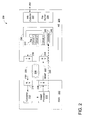
- FIG. 2 is a logic block diagram 200 illustrating a process of information transfer between an EMS and an NE during a network discovery process in accordance with one embodiment of the present invention.
- Diagram 200 includes an EMS 202 , an NE 206 , and a connection 208 .
- Connection 208 can be a wired and/or wireless connection between EMS 202 and NE 206 .
- Connection 208 can be a point to point or through a network.
- connection 208 is capable of transferring data using SNMP 222 and/or FTP 220 . It should be noted that the underlying concept of the exemplary embodiment(s) of the present invention would not change if one or more blocks (or elements or connections) were added to or removed from diagram 200 .
- EMS 202 in one embodiment, includes a SNMP processor 210 , a converter 212 , a receiver 216 , and a transmitter 218 .
- Receiver 216 and transmitter 218 in one example, can be configured in the same component.
- SNMP processor 210 executes or processes information in SNMP and is also capable of issuing SNMP commands to NE 206 through transmitter 218 via connection 208 .
- convert 212 Upon receipt of an FTP file by receiver 216 , convert 212 , in one embodiment, converts information in the FTP file from FTP to SNMP before the information is forwarded to SNMP processor 210 for processing.
- NE 206 in one embodiment, includes a storage location 230 , information collector 232 , a file builder 234 , a receiver 236 , and a transmitter 238 . While information collector 232 collects the connection information from other network nodes and/or devices via connection 250 , file builder 234 creates a file in FTP format to save NE and connection information in the file. The file is subsequently stored in storage location 230 before it is being pushed to EMS 202 . Receiver 236 is responsible to receive SNMP data 222 from transmitter 218 via connection 208 , while transmitter 238 is capable of transferring FTP file 220 to EMS 202 via connection 208 .
- Storage location 230 further includes a storage controller 246 and multiple memories 240 - 242 wherein each memory is configured as a file system to store files.
- Each file is formatted in the management protocol syntax used by the EMS (e.g. SNMP) containing discovery information including circuit 1 , circuit 2 , and so on.
- Storage controller 246 in one embodiment, is configured to receive controlling signals from EMS 202 via connection 226 .
- SNMP processor 210 issues a pull SNMP command to controller 246 .
- controller 246 releases the file to EMS 202 through transmitter 238 via connection 208 using FTP.
- EMS 202 issues a SNMP command for deletion to controller 246 via connection 226 .
- the file is subsequently deleted from storage location 230 as soon as the SNMP command for deletion is received and processed.
- EMS 202 In one operation, sends an SNMP request 222 which triggers the creation of a file.
- NE 206 subsequently generates the file in SNMP format which contains the wanted circuit information in memory 240 .
- EMS 202 then retrieves the file from NE 206 via SFTP/TFTP 220 .
- file builder 234 is capable of zipping the file in ASCII format for the file compression.
- ASCII format can be organized as a Varbind having multiple fields including object ID (“OID”) field.
- OID object ID
- Varbind section of a response protocol data unit (“PDU”) is similar to SNMP variable bindings wherein each section includes an OID, index, type, length and a fully tagged value.
- a binary file can be used for file compression. Using file compression mechanism to compress large amount of data before file transfer can speed up discovery process and/or network reconfiguration upon occurrence of a switch-over.
- management systems or EMSs are capable of sending configuration updates or controlling requests to NEs and/or other network devices through an operational protocol to actively manage the system. Reconfigurations and/or control operations, for example, are initiated when changes in the network infrastructure has occurred.
- information accessible via SNMP may be organized in hierarchies, which are described by MIB. It should be noted that SNMP is part of network management architecture. MIB stores a list of managed objects residing in information storage.
- EMS is responsible for managing deleting the generated file through a separate set of requests (or commands).
- An NE allocates a file with a maximum file size or capacity that a system allows.
- a read-write value for example, can be used to indicate that a file has reached the maximum capacity which is allocated. If the size of a generated file exceeds the maximum size, NE stops file generation and issues an error message (e.g. an SNMP trap).
- EMS is required to delete or remove any unwanted or old file(s) in order to restore future file generation.
- SNMP commands “auto-push/auto-delete” and “pull” are the two (2) methods for EMS to retrieve the file from the NE.
- EMS pulls the file via FTP after the file generation is completed.
- an auto-push/auto-delete command upon sending the file from the NE storage location, the file is deleted.
- messages (or traps) for file generation completed and file transfer completed may be sent out.
- a user can query a status for a specific file generation via SNMP and subsequently receive a file generation status report (or message) including approximate percentage completion of the file generation.
- An advantage of using FTP file for transferring bulk data is to transmit large amount of data more efficiently between network devices.
- FIG. 3 is a logic block diagram 300 illustrating a process of information transfer between an EMS and an NE during a switch-over in accordance with one embodiment of the present invention.
- Diagram 300 similar to diagram 200 illustrated in FIG. 2 , includes an EMS 202 , an NE 306 , and a connection 208 .
- Connection 208 can be a wired and/or wireless connection between EMS 202 and NE 206 wherein the connection can be point to point or through a network.
- connection 208 is capable of transferring data using SNMP 222 and/or FTP 220 . It should be noted that the underlying concept of the exemplary embodiment(s) of the present invention would not change if one or more blocks (or elements or connections) were added to or removed from diagram 300 .
- NE 206 in one embodiment, is a backup controller 346 including a storage location 330 , information collector 332 , a buffer 310 , a file builder 234 , a receiver 236 , and a transmitter 238 . While information collector 332 collects switch-over information such as routing packets between network nodes and/or devices via connection 250 , the routing information is stored in buffer 310 during a switch-over scenario. During a period of a switch-over, when the primary controller 246 (see FIG. 2 ), for instance, stops processing the incoming packets and the backup controller 346 is in the process of taking over the routing responsibility, newly arrived incoming packets which could be large amount of data are temporarily stored in buffer 310 .
- File builder 334 creates a file and encapsulates the stored incoming packets in the file. The file is subsequently stored in storage location 330 until the file reaches its capacity. Once the file building is completed, it is pushed to EMS 202 .
- Receiver 236 is responsible to receive SNMP data 222 from transmitter 218 and transmitter 238 is capable of transferring the file via FTP 220 to EMS 202 via connection 208 .
- Storage location 330 further includes a storage controller 346 and multiple memories 340 - 342 wherein each memory is configured as a file system to store files up to the maximum storage capacity allowed. Each file contains buffered data, wherein storage location 330 is capable of storing multiple files with multiple buffered data.
- Storage controller 346 in one embodiment, is configured to receive controlling signals from EMS 202 via connection 226 . For example, after the file is built, SNMP processor 210 issues a pull SNMP command. Upon receipt of the pull SNMP command, controller 346 releases the file to EMS 202 via transmitter 238 . After receipt of the file, EMS 202 can issue a SNMP command of deletion to controller 346 via connection 226 , the file is subsequently deleted from storage location 330 .
- EMS 202 In one operation, sends an SNMP request 222 which triggers a file creation.
- Backup controller 346 subsequently generates a file which contains the incoming information in memory 340 .
- EMS 202 then retrieves the file from NE 306 using SFTP/TFTP 220 .
- the exemplary aspect of the present invention includes various processing steps, which will be described below.
- the steps of the aspect may be embodied in machine or computer executable instructions.
- the instructions can be used to cause a general purpose or special purpose system, which is programmed with the instructions, to perform the steps of the exemplary aspect of the present invention.
- the steps of the exemplary aspect of the present invention may be performed by specific hardware components that contain hard-wired logic for performing the steps, or by any combination of programmed computer components and custom hardware components.
- FIG. 4 is a flowchart 400 illustrating a process of establishing a file for a network discovery process in accordance with one embodiment of the present invention.
- a process capable of generating a file for transferring bulk data between EMS and NE examines whether the current task or occasion is a network discovery process. If the current task is not the discovery process, the process proceeds to block 420 to monitor a switch-over occurrence. If, on the other hand, the current occasion is a discovery process, the process moves to block 404 .
- the process issues an SNMP command to one or more NEs requesting a file generation.
- the process proceeds to block 408 .
- a file is built at block 410 , wherein the file includes information regarding obtained circuit(s).
- the process loops back to block 406 to determine whether there is additional circuit(s) that has not been discovered.
- the process proceeds to block 414 .
- the NE issues a signal indicating that the file is completed.
- the process pushes the file from NE to EMS.
- the file is converted to data formatted in SNMP and proceeds to block 440 .
- the process activates a monitoring application to detect switch-over condition(s) between a primary controller and a backup controller. If switch-over is not detected at block 422 , the process loops back to block 420 and the process continues to monitor. If, however, a switch-over has occurred at block 422 , the process proceeds to block 426 to receive incoming packet information. Upon obtaining incoming packet data at block 428 , a file is built to include incoming packet data at block 430 . After storing the file at a local storage location at block 432 , the process loops back to block 426 to determine whether there is more incoming packet information over the network or in a local buffer.
- the process proceeds to issue a signal of file completion to EMS at block 434 . It should be noted that when a backup controller is up and running, the subsequent incoming packet should be routed quickly. After issuing a command of pull the file at block 436 , the process converts information carried by the file to SNMP. At block 440 , the process ends after the local storage location is reset.
- FIG. 5 is a flowchart 500 illustrating an exemplary process of file building in an NE in accordance with one embodiment of the present invention.
- a process of information transfer initiates a command of file generation formatted in a first network protocol to an NE during a network configuration phase. While the first network protocol can be SNMP, the network configuration phase is a network discovery process.
- the process obtains configuration information or discovery information from one or more network devices.
- the process collects information relating to network circuits from other routers.
- the process establishes or creates or generates a file containing the configuration information and subsequently stores the file in a storage location.
- the process formats the file and encapsulates the configuration information and/or discovery information including network circuits in the file.
- the process is capable of forwarding the file formatted in a second network protocol to a network manager.
- the network manager can be EMS
- the second network protocol can be FTP, SFTP, or TFTP.
- the process also sends a deletion command from the network manager to delete the file. After identifying the storage located in the NE, the process deletes the file from the storage location in response to the deletion command.
- the FTP file can facilitate bulk data transfer between an NE and an EMS.
- the process converts the information carried by the file from FTP to SNMP after the file is received by the EMS, so that the information being transferred using FTP looks as it was transferred using SNMP to the EMS applications.
- the process allows EMS to manage or control the storage location situated in the NE.
Abstract
Description
Claims (17)
Priority Applications (1)
| Application Number | Priority Date | Filing Date | Title |
|---|---|---|---|
| US12/465,073 US8972561B1 (en) | 2009-05-13 | 2009-05-13 | Methods and apparatus for obtaining network information using file transfer |
Applications Claiming Priority (1)
| Application Number | Priority Date | Filing Date | Title |
|---|---|---|---|
| US12/465,073 US8972561B1 (en) | 2009-05-13 | 2009-05-13 | Methods and apparatus for obtaining network information using file transfer |
Publications (1)
| Publication Number | Publication Date |
|---|---|
| US8972561B1 true US8972561B1 (en) | 2015-03-03 |
Family
ID=52575209
Family Applications (1)
| Application Number | Title | Priority Date | Filing Date |
|---|---|---|---|
| US12/465,073 Active 2032-08-29 US8972561B1 (en) | 2009-05-13 | 2009-05-13 | Methods and apparatus for obtaining network information using file transfer |
Country Status (1)
| Country | Link |
|---|---|
| US (1) | US8972561B1 (en) |
Cited By (9)
| Publication number | Priority date | Publication date | Assignee | Title |
|---|---|---|---|---|
| US20160011822A1 (en) * | 2010-04-26 | 2016-01-14 | Canon Kabushiki Kaisha | Image sending apparatus and authentication method in image sending apparatus |
| CN105656686A (en) * | 2016-02-29 | 2016-06-08 | 中国人民解放军国防信息学院 | Self-adaptive equipment management adaptation method |
| CN106375116A (en) * | 2016-08-30 | 2017-02-01 | 成都广达新网科技股份有限公司 | Network cell equipment configuration information checking system and working method thereof |
| CN106789266A (en) * | 2016-12-27 | 2017-05-31 | 武汉船舶通信研究所 | A kind of Network Management Equipment, network element device and network management system |
| CN108509144A (en) * | 2017-02-27 | 2018-09-07 | 中兴通讯股份有限公司 | Data save method and device |
| US20180270100A1 (en) * | 2014-12-19 | 2018-09-20 | Thomson Licensing | Method and apparatus for data transfer between network devices |
| CN111669364A (en) * | 2020-04-26 | 2020-09-15 | 视联动力信息技术股份有限公司 | Data transmission method, device, electronic equipment and medium |
| CN113014405A (en) * | 2019-12-19 | 2021-06-22 | 中兴通讯股份有限公司 | Processing method of data acquisition instruction, SNMP proxy equipment and storage medium |
| CN117440410A (en) * | 2023-12-21 | 2024-01-23 | 广州通则康威科技股份有限公司 | FTP protocol-based debugging control method and debugging controller |
Citations (15)
| Publication number | Priority date | Publication date | Assignee | Title |
|---|---|---|---|---|
| US5592620A (en) * | 1993-08-12 | 1997-01-07 | International Business Machines Corporation | System and method for controlling, monitoring and retrieving accounting data |
| US6341127B1 (en) * | 1997-07-11 | 2002-01-22 | Kabushiki Kaisha Toshiba | Node device and method for controlling label switching path set up in inter-connected networks |
| US20020161885A1 (en) * | 1999-10-27 | 2002-10-31 | Netbotz Inc. | Methods for displaying physical network topology and environmental status by location, organization, or responsible party |
| US20020161883A1 (en) * | 2001-04-30 | 2002-10-31 | David Matheny | System and method for collecting, aggregating, and coalescing network discovery data |
| US20030012182A1 (en) * | 2001-07-12 | 2003-01-16 | Takayuki Sato | Management method for network device |
| US20030033282A1 (en) * | 2001-07-19 | 2003-02-13 | Seiko Epson Corporation | Method for linking management-information database structure definition files, network device management system, and process program for linking management-information database structure definition files |
| US20030154269A1 (en) * | 2002-02-14 | 2003-08-14 | Nyanchama Matunda G. | Method and system for quantitatively assessing computer network vulnerability |
| US20030167319A1 (en) * | 2001-08-08 | 2003-09-04 | Prema Venkatesulu | Performance of lifetest using CMTS as a proxy |
| US20030208480A1 (en) * | 2002-05-03 | 2003-11-06 | Netbotz, Inc. | Method and apparatus for collecting and displaying network device information |
| US20050050225A1 (en) * | 2003-08-29 | 2005-03-03 | Tatman Lance A. | System and method for discovery of BGP router topology |
| US20050273593A1 (en) * | 2002-06-03 | 2005-12-08 | Seminaro Michael D | Method and system for filtering and suppression of telemetry data |
| US20050289197A1 (en) * | 2004-06-25 | 2005-12-29 | Nec Corporation | Replication system having the capability to accept commands at a standby-system site before completion of updating thereof |
| US20060092861A1 (en) * | 2004-07-07 | 2006-05-04 | Christopher Corday | Self configuring network management system |
| US20090067331A1 (en) * | 2007-09-10 | 2009-03-12 | Juniper Networks, Inc. | Routing network packets based on electrical power procurement arrangements |
| US20100085971A1 (en) * | 2004-11-19 | 2010-04-08 | Etelemetry, Inc. | Computer tracking and locking |
-
2009
- 2009-05-13 US US12/465,073 patent/US8972561B1/en active Active
Patent Citations (15)
| Publication number | Priority date | Publication date | Assignee | Title |
|---|---|---|---|---|
| US5592620A (en) * | 1993-08-12 | 1997-01-07 | International Business Machines Corporation | System and method for controlling, monitoring and retrieving accounting data |
| US6341127B1 (en) * | 1997-07-11 | 2002-01-22 | Kabushiki Kaisha Toshiba | Node device and method for controlling label switching path set up in inter-connected networks |
| US20020161885A1 (en) * | 1999-10-27 | 2002-10-31 | Netbotz Inc. | Methods for displaying physical network topology and environmental status by location, organization, or responsible party |
| US20020161883A1 (en) * | 2001-04-30 | 2002-10-31 | David Matheny | System and method for collecting, aggregating, and coalescing network discovery data |
| US20030012182A1 (en) * | 2001-07-12 | 2003-01-16 | Takayuki Sato | Management method for network device |
| US20030033282A1 (en) * | 2001-07-19 | 2003-02-13 | Seiko Epson Corporation | Method for linking management-information database structure definition files, network device management system, and process program for linking management-information database structure definition files |
| US20030167319A1 (en) * | 2001-08-08 | 2003-09-04 | Prema Venkatesulu | Performance of lifetest using CMTS as a proxy |
| US20030154269A1 (en) * | 2002-02-14 | 2003-08-14 | Nyanchama Matunda G. | Method and system for quantitatively assessing computer network vulnerability |
| US20030208480A1 (en) * | 2002-05-03 | 2003-11-06 | Netbotz, Inc. | Method and apparatus for collecting and displaying network device information |
| US20050273593A1 (en) * | 2002-06-03 | 2005-12-08 | Seminaro Michael D | Method and system for filtering and suppression of telemetry data |
| US20050050225A1 (en) * | 2003-08-29 | 2005-03-03 | Tatman Lance A. | System and method for discovery of BGP router topology |
| US20050289197A1 (en) * | 2004-06-25 | 2005-12-29 | Nec Corporation | Replication system having the capability to accept commands at a standby-system site before completion of updating thereof |
| US20060092861A1 (en) * | 2004-07-07 | 2006-05-04 | Christopher Corday | Self configuring network management system |
| US20100085971A1 (en) * | 2004-11-19 | 2010-04-08 | Etelemetry, Inc. | Computer tracking and locking |
| US20090067331A1 (en) * | 2007-09-10 | 2009-03-12 | Juniper Networks, Inc. | Routing network packets based on electrical power procurement arrangements |
Cited By (14)
| Publication number | Priority date | Publication date | Assignee | Title |
|---|---|---|---|---|
| US20160011822A1 (en) * | 2010-04-26 | 2016-01-14 | Canon Kabushiki Kaisha | Image sending apparatus and authentication method in image sending apparatus |
| US10838667B2 (en) * | 2010-04-26 | 2020-11-17 | Canon Kabushiki Kaisha | Image sending apparatus and authentication method in image sending apparatus |
| US20180270100A1 (en) * | 2014-12-19 | 2018-09-20 | Thomson Licensing | Method and apparatus for data transfer between network devices |
| CN105656686A (en) * | 2016-02-29 | 2016-06-08 | 中国人民解放军国防信息学院 | Self-adaptive equipment management adaptation method |
| CN105656686B (en) * | 2016-02-29 | 2018-08-10 | 中国人民解放军国防信息学院 | Adaptive equipment management adaptation method |
| CN106375116A (en) * | 2016-08-30 | 2017-02-01 | 成都广达新网科技股份有限公司 | Network cell equipment configuration information checking system and working method thereof |
| CN106789266A (en) * | 2016-12-27 | 2017-05-31 | 武汉船舶通信研究所 | A kind of Network Management Equipment, network element device and network management system |
| CN108509144A (en) * | 2017-02-27 | 2018-09-07 | 中兴通讯股份有限公司 | Data save method and device |
| CN108509144B (en) * | 2017-02-27 | 2020-12-15 | 中兴通讯股份有限公司 | Data saving method and device |
| CN113014405A (en) * | 2019-12-19 | 2021-06-22 | 中兴通讯股份有限公司 | Processing method of data acquisition instruction, SNMP proxy equipment and storage medium |
| CN111669364A (en) * | 2020-04-26 | 2020-09-15 | 视联动力信息技术股份有限公司 | Data transmission method, device, electronic equipment and medium |
| CN111669364B (en) * | 2020-04-26 | 2023-09-12 | 视联动力信息技术股份有限公司 | Data transmission method, device, electronic equipment and medium |
| CN117440410A (en) * | 2023-12-21 | 2024-01-23 | 广州通则康威科技股份有限公司 | FTP protocol-based debugging control method and debugging controller |
| CN117440410B (en) * | 2023-12-21 | 2024-03-12 | 广州通则康威科技股份有限公司 | FTP protocol-based debugging control method and debugging controller |
Similar Documents
| Publication | Publication Date | Title |
|---|---|---|
| US8972561B1 (en) | Methods and apparatus for obtaining network information using file transfer | |
| US9544182B2 (en) | Monitoring gateway systems and methods for openflow type networks | |
| EP2811702A1 (en) | Network system and topology management method | |
| US20120136996A1 (en) | Method for managing network and for providing service qos | |
| CN116208524A (en) | Method, equipment and system for detecting data message | |
| WO2009089742A1 (en) | Distributed network management collection system, realization method and corresponding device | |
| CN100391156C (en) | Communication system and terminal | |
| US20050076112A1 (en) | System and method for management of remote devices in a network | |
| CN112367217A (en) | Cooperative type large flow detection method and system oriented to software defined network | |
| Hu et al. | Design and demonstration of SDN-based flexible flow converging with protocol-oblivious forwarding (POF) | |
| JP5708818B2 (en) | COMMUNICATION DEVICE, COMMUNICATION METHOD, AND PROGRAM | |
| CN107566277B (en) | Topology determining method, message response method, controller and switch | |
| CN112672363B (en) | Method and device for confirming telemetry capability of stream information | |
| US8275869B2 (en) | Re-synchronizing data between network elements and network management system using partial node discovery | |
| US8098688B1 (en) | Methods and apparatus for optimizing network management traffic using dynamic SNMP packet resizing | |
| CN108390899B (en) | Software defined network-based method for content collaboration of two-layer switch | |
| JP6525256B2 (en) | Virtual network system and virtual network route setting method | |
| US20210014117A1 (en) | Terminal device management method, server, and terminal device for managing terminal devices in local area network | |
| CN116346634A (en) | State sensing information processing method and device of network management and control system and electronic equipment | |
| CN113300869B (en) | Communication method with in-band network remote sensing function, network device and storage medium | |
| CN105592485A (en) | Method for collecting and processing messages in real time based on SNMP | |
| CN114363399B (en) | Control method and system of edge gateway | |
| CN109617729B (en) | Method and system for switching PTN network element into SPTN network element | |
| CN108712458B (en) | Software defined network controller supporting content control | |
| CN113452471A (en) | Method, electronic device and computer program product for data processing |
Legal Events
| Date | Code | Title | Description |
|---|---|---|---|
| AS | Assignment |
Owner name: TELLABS SAN JOSE, INC., ILLINOIS Free format text: ASSIGNMENT OF ASSIGNORS INTEREST;ASSIGNORS:LEVESQUE, GILBERT;DEY, DEBASHIS;GIRI, PRAKASH;AND OTHERS;REEL/FRAME:022677/0432 Effective date: 20090508 |
|
| AS | Assignment |
Owner name: TELLABS OPERAIONS INC., ILLINOIS Free format text: MERGER;ASSIGNOR:TELLABS SAN JOSE INC.;REEL/FRAME:027799/0753 Effective date: 20111230 |
|
| AS | Assignment |
Owner name: TELECOM HOLDING PARENT LLC, CALIFORNIA Free format text: ASSIGNMENT FOR SECURITY - - PATENTS;ASSIGNORS:CORIANT OPERATIONS, INC.;TELLABS RESTON, LLC (FORMERLY KNOWN AS TELLABS RESTON, INC.);WICHORUS, LLC (FORMERLY KNOWN AS WICHORUS, INC.);REEL/FRAME:034484/0740 Effective date: 20141126 |
|
| FEPP | Fee payment procedure |
Free format text: PAYOR NUMBER ASSIGNED (ORIGINAL EVENT CODE: ASPN); ENTITY STATUS OF PATENT OWNER: LARGE ENTITY |
|
| STCF | Information on status: patent grant |
Free format text: PATENTED CASE |
|
| AS | Assignment |
Owner name: CERBERUS BUSINESS FINANCE, LLC, AS COLLATERAL AGEN Free format text: SECURITY INTEREST;ASSIGNOR:CORIANT OPERATIONS, INC.;REEL/FRAME:042693/0888 Effective date: 20170613 |
|
| AS | Assignment |
Owner name: TELECOM HOLDING PARENT LLC, CALIFORNIA Free format text: CORRECTIVE ASSIGNMENT TO CORRECT THE REMOVE APPLICATION NUMBER 10/075,623 PREVIOUSLY RECORDED AT REEL: 034484 FRAME: 0740. ASSIGNOR(S) HEREBY CONFIRMS THE ASSIGNMENT FOR SECURITY --- PATENTS;ASSIGNORS:CORIANT OPERATIONS, INC.;TELLABS RESTON, LLC (FORMERLY KNOWN AS TELLABS RESTON, INC.);WICHORUS, LLC (FORMERLY KNOWN AS WICHORUS, INC.);REEL/FRAME:042980/0834 Effective date: 20141126 |
|
| MAFP | Maintenance fee payment |
Free format text: PAYMENT OF MAINTENANCE FEE, 4TH YEAR, LARGE ENTITY (ORIGINAL EVENT CODE: M1551); ENTITY STATUS OF PATENT OWNER: LARGE ENTITY Year of fee payment: 4 |
|
| MAFP | Maintenance fee payment |
Free format text: PAYMENT OF MAINTENANCE FEE, 8TH YEAR, LARGE ENTITY (ORIGINAL EVENT CODE: M1552); ENTITY STATUS OF PATENT OWNER: LARGE ENTITY Year of fee payment: 8 |