US8991885B2 - Compliant underactuated grasper - Google Patents
Compliant underactuated grasper Download PDFInfo
- Publication number
- US8991885B2 US8991885B2 US13/833,631 US201313833631A US8991885B2 US 8991885 B2 US8991885 B2 US 8991885B2 US 201313833631 A US201313833631 A US 201313833631A US 8991885 B2 US8991885 B2 US 8991885B2
- Authority
- US
- United States
- Prior art keywords
- grasper
- joint
- face
- phalanx
- distal
- Prior art date
- Legal status (The legal status is an assumption and is not a legal conclusion. Google has not performed a legal analysis and makes no representation as to the accuracy of the status listed.)
- Active, expires
Links
Images


Classifications
-
- B—PERFORMING OPERATIONS; TRANSPORTING
- B25—HAND TOOLS; PORTABLE POWER-DRIVEN TOOLS; MANIPULATORS
- B25J—MANIPULATORS; CHAMBERS PROVIDED WITH MANIPULATION DEVICES
- B25J15/00—Gripping heads and other end effectors
- B25J15/08—Gripping heads and other end effectors having finger members
- B25J15/10—Gripping heads and other end effectors having finger members with three or more finger members
- B25J15/103—Gripping heads and other end effectors having finger members with three or more finger members for gripping the object in three contact points
-
- B—PERFORMING OPERATIONS; TRANSPORTING
- B25—HAND TOOLS; PORTABLE POWER-DRIVEN TOOLS; MANIPULATORS
- B25J—MANIPULATORS; CHAMBERS PROVIDED WITH MANIPULATION DEVICES
- B25J15/00—Gripping heads and other end effectors
- B25J15/0009—Gripping heads and other end effectors comprising multi-articulated fingers, e.g. resembling a human hand
-
- B—PERFORMING OPERATIONS; TRANSPORTING
- B25—HAND TOOLS; PORTABLE POWER-DRIVEN TOOLS; MANIPULATORS
- B25J—MANIPULATORS; CHAMBERS PROVIDED WITH MANIPULATION DEVICES
- B25J15/00—Gripping heads and other end effectors
- B25J15/04—Gripping heads and other end effectors with provision for the remote detachment or exchange of the head or parts thereof
- B25J15/0475—Exchangeable fingers
-
- B—PERFORMING OPERATIONS; TRANSPORTING
- B25—HAND TOOLS; PORTABLE POWER-DRIVEN TOOLS; MANIPULATORS
- B25J—MANIPULATORS; CHAMBERS PROVIDED WITH MANIPULATION DEVICES
- B25J15/00—Gripping heads and other end effectors
- B25J15/08—Gripping heads and other end effectors having finger members
- B25J15/10—Gripping heads and other end effectors having finger members with three or more finger members
-
- B—PERFORMING OPERATIONS; TRANSPORTING
- B25—HAND TOOLS; PORTABLE POWER-DRIVEN TOOLS; MANIPULATORS
- B25J—MANIPULATORS; CHAMBERS PROVIDED WITH MANIPULATION DEVICES
- B25J9/00—Programme-controlled manipulators
- B25J9/0009—Constructional details, e.g. manipulator supports, bases
- B25J9/0015—Flexure members, i.e. parts of manipulators having a narrowed section allowing articulation by flexion
-
- B—PERFORMING OPERATIONS; TRANSPORTING
- B25—HAND TOOLS; PORTABLE POWER-DRIVEN TOOLS; MANIPULATORS
- B25J—MANIPULATORS; CHAMBERS PROVIDED WITH MANIPULATION DEVICES
- B25J9/00—Programme-controlled manipulators
- B25J9/10—Programme-controlled manipulators characterised by positioning means for manipulator elements
- B25J9/104—Programme-controlled manipulators characterised by positioning means for manipulator elements with cables, chains or ribbons
-
- Y—GENERAL TAGGING OF NEW TECHNOLOGICAL DEVELOPMENTS; GENERAL TAGGING OF CROSS-SECTIONAL TECHNOLOGIES SPANNING OVER SEVERAL SECTIONS OF THE IPC; TECHNICAL SUBJECTS COVERED BY FORMER USPC CROSS-REFERENCE ART COLLECTIONS [XRACs] AND DIGESTS
- Y10—TECHNICAL SUBJECTS COVERED BY FORMER USPC
- Y10S—TECHNICAL SUBJECTS COVERED BY FORMER USPC CROSS-REFERENCE ART COLLECTIONS [XRACs] AND DIGESTS
- Y10S901/00—Robots
- Y10S901/30—End effector
- Y10S901/31—Gripping jaw
- Y10S901/39—Jaw structure
Definitions
- DARPA Defense Advanced Research Projects Agency
- ARM-H DARPA Autonomous Robot Manipulation-Hardware Track
- End effectors or graspers are commonly mounted on a robotic arm and used to manipulate and/or grasp objects in a selected environment.
- the environment may be structured or unstructured.
- a compliant underactuated grasper includes a base and a plurality of fingers. At least one of the plurality of fingers includes: a proximal phalanx; a proximal joint connecting the proximal phalanx to the base; a distal phalanx; a distal joint connecting the distal phalanx to the proximal phalanx; and a member for moving the phalanges. At least one of the proximal joint and the distal joint includes a flexure joint, the flexure joint having a first compliance in a first direction of the flexure joint and a second compliance in a second direction of the flexure joint, wherein the second compliance is stiffer than the first compliance.
- the distal phalanx includes: a rounded end face; and a lifting portion including a lifting edge adjacent the rounded end face.
- the member acts in parallel to the first direction of the flexure joint.
- the grasper further includes at least one actuator associated with the member. The grasper has fewer actuators than degrees of freedom.
- the lifting edge is a free terminal edge
- the distal phalanx includes a lifting groove defined between the rounded end face and the lifting edge.
- the rounded end face defines an arc in a plane substantially perpendicular to a longitudinal axis of the lifting groove.
- the lifting groove has a depth in the range of from about 1 mm to 3 mm.
- the rounded end face may be formed of a softer material than the lifting portion.
- the softer material of the rounded end face has a hardness in the range of from about 0 Shore A to 60 Shore A, and the lifting portion has a hardness of at least about 100 GPa.
- the grasper may include an adjustment mechanism operable to selectively adjust the position of the lifting edge relative to the rounded end face.
- the distal phalanx has a substantially planar inner grasping face and distinct, opposed, axially extending inner side edges.
- a compliant underactuated grasper includes a base and a plurality of fingers. At least one of the plurality of fingers includes: a proximal phalanx; a proximal joint connecting the proximal phalanx to the base; a distal phalanx; a distal joint connecting the distal phalanx to the proximal phalanx; and a member for moving the phalanges. At least one of the proximal joint and the distal joint includes a flexure joint, the flexure joint having a first compliance in a first direction of the flexure joint and a second compliance in a second direction of the flexure joint, wherein the second compliance is stiffer than the first compliance.
- the member acts in parallel to the first direction of the flexure joint.
- the grasper further includes at least one actuator associated with the member.
- the distal phalanx has a substantially planar inner grasping face and distinct, opposed, axially extending inner side edges.
- the grasper has fewer actuators than degrees of freedom.
- the planar inner grasping face is substantially parallel to a primary bending axis of the flexure joint.
- the planar inner grasping face may be formed of an elastomeric material.
- the flexure joint includes a flexure link formed of an elastomeric material.
- the distal phalanx is substantially rectangular in cross-section perpendicular to the first direction.
- a compliant underactuated grasper includes a base, two finger digits and a thumb digit opposing the two finger digits.
- the finger digits and the thumb digit each include: a proximal phalanx; a distal phalanx; a distal joint directly connecting the proximal phalanx to the distal phalanx, the distal joint being compliant in a first direction; a proximal joint directly connecting the proximal phalanx to the base, the proximal joint being compliant in a second direction; and a tendon cable for moving the proximal and distal phalanges, wherein the tendon cable is substantially parallel to the first direction of compliance and substantially changes the compliance of the distal joint in the first direction.
- the grasper further includes at least one actuator to move the finger digits and thumb digit.
- Each distal phalanx has a length that is 0.60 to 0.66 times the length of the proximal phalanx connected thereto.
- An average distance from the proximal joint of each of the two finger digits to the thumb is 1.30 to 1.44 times the average length of the proximal phalanges of the two finger digits.
- the grasper has fewer actuators than degrees of freedom.
- the base includes a palm between the finger digits and the thumb digit, and the palm has a major dimension that is in the range of from about 1.21 to 1.33 times the average length of the proximal phalanges.
- a spacing between the proximal joints of the finger digits is in the range of from about 0.97 to 1.08 times the average length of the proximal phalanges.
- FIG. 1 is a fragmentary, perspective view of a robot including a grasper according to embodiments of the invention.
- FIG. 2 is a front perspective view of the grasper of FIG. 1 .
- FIG. 3 is a rear perspective view of the grasper of FIG. 1 .
- FIG. 4 is a cross-sectional view of the grasper of FIG. 1 taken along the line 4 - 4 of FIG. 1 .
- FIG. 5 is a cross-sectional view of the grasper of FIG. 1 taken along the line 5 - 5 of FIG. 1 .
- FIG. 6 is a top plan view of the grasper of FIG. 1 .
- FIG. 7 is a side elevational view of the grasper of FIG. 1 .
- FIG. 8 is a rear elevational view of the grasper of FIG. 1 .
- FIG. 9 is a top perspective view of a finger forming a part of the grasper of FIG. 1 .
- FIG. 10 is a bottom perspective view of the finger of FIG. 9 .
- FIG. 11 is a cross-sectional view of the finger of FIG. 9 taken along the line 11 - 11 of FIG. 9 .
- FIG. 12 is an enlarged, fragmentary, side view of the finger of FIG. 9 .
- FIG. 13 is a top plan view of the finger of FIG. 9 .
- FIG. 14 is a side view of the finger of FIG. 9 .
- FIG. 15 is a top perspective view of the finger of FIG. 9 and an associated magnetic breakaway system.
- FIG. 16 is an exploded, fragmentary, bottom perspective view of the finger and magnetic breakaway system of FIG. 15 .
- FIG. 17 is an exploded, fragmentary, top perspective view of the finger and magnetic breakaway system of FIG. 15 .
- FIG. 18 is a cross-sectional view of the magnetic breakaway system of FIG. 15 taken along the line 18 - 18 of FIG. 15 .
- FIG. 19 is a cross-sectional view of the magnetic breakaway system of FIG. 15 taken along the line 19 - 19 of FIG. 15 .
- FIG. 20 is an exploded, fragmentary, cross-sectional, bottom perspective view of the magnetic breakaway system of FIG. 15 .
- FIG. 21 is a top perspective view of a base forming a part of the grasper of FIG. 1 including submounts forming a part of the magnetic breakaway system.
- FIG. 22 is a fragmentary, perspective view of the finger and magnetic breakaway system of FIG. 15 illustrating operation of the magnetic breakaway system.
- FIGS. 23-29 illustrate various finger configurations that can be executed by the grasper of FIG. 1 .
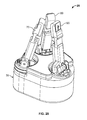
- FIGS. 30A and 30B illustrate a sequence of movements of the grasper of FIG. 1 to grab and pick up an object.
- spatially relative terms such as “under”, “below”, “lower”, “over”, “upper” and the like, may be used herein for ease of description to describe one element or feature's relationship to another element(s) or feature(s) as illustrated in the figures. It will be understood that the spatially relative terms are intended to encompass different orientations of the device in use or operation in addition to the orientation depicted in the figures. For example, if the device in the figures is turned over, elements described as “under” or “beneath” other elements or features would then be oriented “over” the other elements or features. Thus, the exemplary term “under” can encompass both an orientation of over and under. The device may be otherwise oriented (rotated 90 degrees or at other orientations) and the spatially relative descriptors used herein interpreted accordingly.
- Embodiments of the present invention are directed to end effectors or graspers.
- a grasper as disclosed herein may form part of a robot or a prosthetic apparatus.
- the grasper may be mounted on a robotic arm and used to manipulate and grasp objects in a structured or unstructured environment.
- the grasper may be employed as a grasper or “hand” of a humanoid robot and/or may comply with the criteria specified under the DARPA Autonomous Robot Manipulation Hardware (ARM-H) program.
- ARM-H DARPA Autonomous Robot Manipulation Hardware
- a robot 10 ( FIG. 1 ) according to embodiments of the invention is shown therein and includes an arm 12 and a grasper 20 rotatably coupled to the arm 12 by a wrist joint 14 .
- the grasper 20 includes a base assembly 30 , a first finger 70 , a second finger 80 , and a thumb 90 .
- the fingers 70 , 80 and the thumb 90 may be identically constructed except for their placement on the base 30 and methods and mechanisms of actuation as discussed below. Except as otherwise noted, “finger” and “fingers” also refer to the thumb 90 .
- the grasper 20 has a primary or longitudinal axis LG-LG ( FIG. 4 ).
- the base 30 includes a first finger actuator 60 , a second finger actuator 62 , a thumb agonist actuator 64 , a thumb antagonist actuator 66 , and a finger rotation actuator 68 .
- the actuators 60 , 62 , 64 , 66 , 68 may be electric motors (e.g., DC motors).
- Tendon cables 60 A and 62 A ( FIG. 4 ) are connected to the fingers 70 and 80 , respectively, to cause controlled movement of the fingers 70 and 80 using the actuators 60 and 62 .
- Tendon cables 64 A, 66 A ( FIG. 5 ) are connected to the thumb 90 to cause controlled movement of the thumb 90 using the actuators 64 and 66 , respectively.
- Each of the fingers 70 , 80 , 90 can be pivoted at a respective proximal pin pivot joint JP about an axis FP-FP ( FIG. 2 ) by the tendons 60 A, 62 A, 64 A, 66 A and the actuators 60 , 62 , 64 , 66 . Additionally, the fingers 70 and 80 can be rotated at respective rotation joints JR about rotation axes FR-FR ( FIG. 8 ) in opposed directions K by the actuator 68 . The fingers 70 and 80 are coupled by a linkage so that they rotate about the joints JR in tandem in opposite directions from each other. Each finger 70 , 80 , 90 can also be bent about a distal compliant flexure joint JC ( FIG. 1 ) as described below.
- the base assembly 30 includes a frame 32 and a palm 34 on an operational side of the frame 32 .
- Three magnet base submounts 160 are mounted in the frame 32 and three associated finger base submounts 40 are mounted thereon ( FIG. 15 ).
- each submount 160 and its associated submount 40 are coupled to function effectively as a single unit.
- the submounts 160 of the fingers 70 and 80 are rotatable at the joints JR.
- the fingers 70 , 80 , 90 may be identically or similarly constructed as discussed above.
- An exemplary finger 70 will be described, and it will be appreciated that this description will likewise apply to the other fingers 80 and 90 .
- the finger 70 includes a proximal phalanx 110 and a distal phalanx 120 coupled by a compliant flexure link 130 at a compliant distal inter-phalanges flexure joint JC.
- the finger 70 also has a hinge feature 112 coupling the finger 70 to its finger base mount 40 .
- the finger 70 has a longitudinal axis LF-LF. More particularly, the proximal phalanx 110 has a proximal end 110 A and a distal end 110 B.
- the distal phalanx 120 has a proximal end 120 A and a distal end 120 B.
- the hinge feature 112 is provided on the end 110 A.
- the flexure link 130 is secured to the ends 110 B and 120 A.
- the end 120 B is free.
- a distal extension or plate member 140 is mounted on the end 120 B.
- the hinge feature 112 is pivotally coupled to a cooperating hinge feature 42 ( FIG. 1 ) on the finger base submount 40 by a pivot pin 50 , which defines the pin pivot axis FP-FP, to form the proximal pin pivot joint JP.
- Rotational movement of the finger 70 about the pivot joint JP is constrained to pivoting about the pivot axis FP-FP in a finger closing pivot direction F and a finger opening pivot direction H.
- the finger 70 defines a finger lateral plane E parallel to each of the longitudinal axis LF-LF and the pivot axis FP-FP. It will be appreciated that the orientation of the pivot axis FP-FP will vary depending on the rotational position of the submount 40 about the axis FR-FR.
- an angle position sensor 54 disposed in the joint JP detects the angular position of the phalanx 110 with respect to the base 30 .
- a magnetic encoder may be mounted on one part of the joint JP (e.g., the hinge feature 42 ) and a cooperating magnet may be mounted on another part of the joint JP (e.g., the hinge feature 112 ).
- a biasing member 52 ( FIGS. 4 and 7 ) is provided in the joint JP.
- the biasing member 52 is a torsion spring and, in particular, may be a helical torsion spring.
- the torsion spring 52 serves as a counter spring or bias return spring. In the absence of restraint from a tendon cable or external force, the torsion spring 52 will force the finger 70 to pivot in a direction I to a wide-open position.
- the flexure link 130 is semi-rigid, flexible, resilient and compliant.
- the flexure link 130 is formed of an elastomeric material.
- the flexure link 130 flexes or bends preferentially about a distal or flexure joint pivot axis FB-FB in each of an inward, primary direction M and an outward direction N.
- the flexure link 130 can also flex or bend in opposed sideward or lateral, secondary directions P perpendicular to or transverse to the finger closing direction F.
- the flexure link 130 and the joint JC have a first compliance in a first direction M and a second compliance in a second direction P.
- the second direction P is perpendicular or transverse to the tendon cable retraction direction H.
- the first compliance is greater than the second compliance (i.e., less force is required to deflect the flexure link 130 in the first direction).
- the flexure link 130 When relaxed and nonloaded, the flexure link 130 will elastically return to a relaxed position or state as shown in FIGS. 9-11 .
- the proximal phalanx 110 and the distal phalanx 120 are substantially parallel or co-axial when the flexure link 130 is in its return position.
- the tendon cable 60 A is routed from the actuator 60 , through tendon raceways 158 , 168 in the submounts 40 , 160 , along the inner side of the hinge feature 112 , through a tendon raceway 118 in the proximal phalanx 110 , across the flexure joint JC, and through a raceway 128 in the distal phalanx 120 , and is anchored to the distal phalanx 120 (e.g., in the raceway 128 ).
- the actuator 60 can draw the tendon cable 60 A through the raceways 118 , 158 , 168 in a direction H to pivot the finger 70 in the closing direction F.
- the actuator 60 can then release or pay out the tendon cable 60 A in the opposite direction to permit the finger 70 to pivot in the opening direction I under the torque of the torsion spring 52 .
- the actuator 60 draws the tendon cable 60 A.
- the spring force or resistance from the torsion spring 52 is less than the stiffness or spring force or bend resistance of the flexure link 130 . Therefore, assuming the proximal phalanx 110 does not encounter external resistance, as the tendon cable 60 A applies tension load to the finger 70 , the finger 70 will be displaced primarily about the pin pivot JP and secondarily about the flexure joint JC.
- proximal phalanx 110 will pivotally rotate a greater angular distance about the pivot pin axis FP-FP than the distal phalanx 120 pivotally rotates or bends about the flexure joint axis FB-FB.
- proximal phalanx 110 is impeded by an external object (e.g., an object grasped) or strikes a limit (e.g., bottoms out on the base 30 ), a greater portion or all of the tension load of the tendon cable 60 A will be applied to the flexure joint JC, and the distal phalanx 120 will then bend or rotate about the flexure joint axis FB-FB at a greater rate than the rate at which the proximal phalanx 110 rotates about the pin pivot axis FP-FP.
- an external object e.g., an object grasped
- a limit e.g., bottoms out on the base 30
- the differential rate of displacement of the phalanges 110 and 120 about their respective pivot axes will depend on the relative effective spring forces of the torsion spring 52 and the flexure link 130 .
- the spring force of the flexure joint JC is at least 8 times the spring force of the pin pivot joint JP and, in some embodiments, is in the range of from about 8 to 12 times the spring force of the pin pivot joint JP.
- the spring rate of the torsion spring 52 is great enough to fully counteract the force of gravity on the finger 70 in any intended orientation when the grasper 20 is static and not acted on by an external object.
- the spring force of the torsion spring 52 is between about 100 and 150 percent of the minimum force necessary to fully counteract the force of gravity on the finger 70 in any intended orientation when the grasper 20 is static and not acted on by an external object.
- the designer can reduce the required spring rate of the flexure joint JC. In turn, the return forces that the actuator 60 must overcome are reduced.
- the spring force of the flexure joint JC can be as high as desired and/or needed.
- the spring force of the flexure joint JC may be increased as the grasper is scaled up in size and used to lift larger and heavier objects.
- FIGS. 1 and 23 - 29 show various configurations of the fingers 70 , 80 , 90 that can be assumed or executed by the grasper 20 .
- FIG. 23 shows a wide open or ready position, wherein the tendon cables 60 A, 62 A, 64 A are slack, permitting the torsion springs 52 to force each finger 70 , 80 , 90 to its limit in its open direction.
- FIG. 1 shows the fingers 70 , 80 in a pinch configuration, which can be achieved when the actuators 60 , 62 pull the fingers 70 , 80 (via the tendon cables 60 A, 62 A) closed without significant resistance.
- the finger rotation actuator 68 may first be used to rotate the fingers 70 , 80 into opposition with one another with their pivot axes FP-FP substantially parallel.
- FIG. 24 illustrates a modified pinch configuration being used to hold and/or manipulate an object 2 such as a flat key.
- FIGS. 23 , 25 and 26 show the fingers 70 , 80 , 90 progressing from the wide open configuration ( FIG. 23 ) to a power grasp configuration ( FIG. 26 ) wherein the thumb 90 crosses the fingers 70 , 80 .
- the rotation actuator 68 may be used to rotate the fingers 70 , 80 into opposition with the thumb 90 with the pivot axes FP-FP of the fingers 70 , 80 , 90 substantially parallel as shown in FIG. 25
- FIG. 27 illustrates a modified power grasp configuration being used to hold and/or manipulate an object 4 such as a power tool.
- the exemplary power tool 4 has a handle 4 A and a trigger 4 B.
- the grasper 20 securely holds the handle 4 A using the fingers 70 , 80 , 90 , and can also be used to operate the trigger 4 B by applying and releasing tension to/from the finger 80 via the tendon cable 62 A so that its distal phalanx 120 will independently bend at the flexure joint JC and press and release the trigger 4 B (the proximal phalanx 110 being limited or constrained by the handle 4 A).
- FIG. 28 shows the fingers 70 , 80 , 90 in a spherical grasp position.
- the fingers 70 , 80 are rotated so that their pivot axes FP-FP extend at an oblique angle to the pivot axis FP-FP of the thumb 90 .
- FIG. 29 illustrates a modified spherical grasp position wherein the grasper 20 is holding an object 6 such as a ball.
- the relationships between the lengths of the phalanges 110 and 120 and the finger and thumb base positions can provide advantageous performance. In some embodiments, these relationships are scalable.
- the length L 1 ( FIG. 13 ) of the proximal phalanx 110 of each finger 70 , 80 is greater than the length L 2 of the distal phalanx 120 of the same finger. According to some embodiments, the length L 1 is in the range of from about 0.60 to 0.66 times the length L 2 .
- the average distance D 1 ( FIG. 6 ) from each finger 70 , 80 base pivot joint JP to the thumb 90 pivot joint JP is in the range of from about 1.30 to 1.44 times the average proximal phalanx length L 1 .
- the major dimension L 3 ( FIG. 6 ) of the palm 34 is in the range of from about 1.21 to 1.33 times the average proximal phalanx length L 1 .
- the spacing D 2 ( FIG. 6 ) between the pivot joints JP of the fingers 70 , 80 is in the range of from about 0.97 to 1.08 times the average proximal phalanx length L 1 .
- each having a proximal pin pivot joint and a distal flexure joint as described may provide certain advantages.
- the rigid pivot at the base of the finger provides pinch stability and torsional strength to facilitate fine manipulation and heavy lifting.
- the flexure joint at the distal joint provides robustness for abuse and enhances the ability of the finger to adapt or conform to unknown shaped objects.
- the pin pivot axis FP-FP of each finger is substantially parallel to the primary flexure axis FB-FB of the finger.
- the grasper 20 is provided with a fingernail system 141 .
- the fingernail system 141 includes a distal plate member 140 mounted on the distal phalanx 120 of each finger 70 , 80 , 90 adjacent the distal end face 124 A thereof. Only one of the fingers 70 will be described hereinbelow. However, it will be appreciated that this description applies likewise to the fingers 80 and 90 .
- the distal plate member 140 includes a base portion 144 and a free terminal lifting edge 142 A.
- the base portion 144 has a slot 144 A and is adjustably secured to the back face 124 C of the phalanx 120 by a fastener 144 B such as a screw.
- the free edge 142 A is located adjacent the end face 124 A.
- the distal plate member 140 has an extension portion 142 terminating in the free edge 142 A and overhanging (cantilevered) or extending axially beyond the location 147 where the plate member 140 diverges from the phalanx 120 to form a ledge.
- the free edge 142 A can be coincident with or inboard of the location 147 .
- the fastener 144 B and groove 144 A can serve as an adjustment mechanism. More particularly, the fastener 144 B can be loosened, the plate member 140 slid to position the edge 142 A as desired relative to the end face 124 A, and the fastener 144 B then re-tightened to secure the plate member 140 in place. It will be appreciated that other suitable adjustment mechanisms can be employed.
- the plate member 142 is relatively thin, at least in the region of the free edge 142 A.
- the free edge 142 A has a thickness T 1 ( FIG. 12 ) in the range of from about 0.02 inch to 0.03 inch.
- the length L 4 of the extension portion 142 from the location 147 to the free edge 142 A is at least 1 mm and, in some embodiments, from about 1.5 mm to 2.5 mm.
- the free edge 142 A is substantially parallel to the flexure joint axis FB-FB.
- the end face 124 A and the plate member 140 are relatively configured and arranged to define a laterally extending slot, groove or undercut 146 between the underside of the extension section 142 and the opposing surface of the end face 124 A.
- the end face 124 A is shaped to cut back axially to form the undercut 146 .
- the end face 124 A is rounded or curvilinear and, in some embodiments, arcuate in cross-section (i.e., in a plane perpendicular to the plane E and parallel to the longitudinal axis of the distal phalanx 120 ).
- the depth D 3 of the undercut 146 is in the range of from about 1 mm to 3 mm.
- the width W 1 of the undercut 146 is in the range of from about 10 mm to 25 mm.
- the plate member 140 is rigid (e.g., formed of steel or stainless steel) and the end face 124 A is relatively soft or compliant (e.g., formed of a pliable rubber).
- the distal phalanx 120 includes a soft pad 125 including the end face 124 A.
- the pad 125 has a durometer in the range of from about 0 Shore A to 60 Shore A and, in some embodiments, from about 10 Shore A to 40 Shore A, and the plate member 140 has a stiffness of at least about 100 GPa and, in some embodiments, at least 180 GPa.
- the plate member 140 can be used to pick up, engage and/or manipulate objects in a manner not possible or that would be cumbersome without the “fingernail”.
- the combination of the thin, rigid plate member 140 (“fingernail”) and the pliable, soft pad 125 (“fingertip) enables the finger to capture an edge of an object therebetween (i.e., in the undercut 146 ).
- a support surface e.g., a table surface
- the plate member 140 can be pressed against the support surface, then translated under the object (between the object and the support surface), and then used to lift the object.
- the compliant flexure joint JC compliments the functionality of the fingernail system 141 .
- the joint compliance enables the plate member 140 to adaptively align with and maintain contact with the support surface.
- the grasper 20 is shown therein performing a sequence of steps or movements to grasp and pick up an object 2 (as shown, a relatively flat key) from a planar surface Z (e.g., a table or floor).
- a planar surface Z e.g., a table or floor
- the key 2 is laid flat on the surface Z.
- the grasper 20 is positioned such that the extension section 142 of the plate member 140 of the finger 70 is placed on the surface Z proximate the side edge 2 A of the key 2 with the undercut 146 and the soft pad 125 overlying the extension section 142 .
- the phalanx 120 of the finger 80 is placed against the surface Z and driven in a direction J toward the key 2 and the finger 70 , the fingers 70 and 80 being relatively disposed in a pinching configuration.
- the finger 80 As the finger 80 is driven in the direction J, it engages the side edge 2 B of the key 2 and pushes the side edge 2 A onto the plate member 140 (in some embodiments, into the undercut 146 and between the extension section 142 and the soft pad 125 ).
- the phalanx 120 of the finger 80 is further driven toward the finger 70 and upward to lift the side edge 2 B off the surface Z.
- the key 2 is thereby flipped or pivoted upwardly about its edge 2 A and toward the end face 124 A of the finger 70 in a direction K as shown in FIG. 30A , the edge 2 A being captured between the plate member 140 and the pad 125 .
- the finger 80 is used to continue lifting the key 2 and converged with the finger 70 until the key 2 is sandwiched between the end faces 124 A of the fingers 70 and 80 , which engage the opposed faces 2 D and 2 C, respectively, of the key 2 .
- a relatively flat object such as a key (or credit card, etc.) can thus be grasped, removed from a planar surface and manipulated using the “fingernail” or fingernails” of the grasper 20 and cooperative movement of the fingers 70 , 80 (and, in some embodiments, the base 30 and/or the arm 12 ).
- the axially extending front side edges 126 A of the distal phalanx 120 are sharp or distinct and the front face 124 B (i.e., the contact or engagement face) is substantially flat or planar ( FIGS. 9 and 10 ).
- the side walls of the distal phalanx 120 forming the side edges 126 A with the front face 124 B are substantially planar at and adjacent the front face 124 B and, in some embodiments, extend substantially perpendicular to the plane of the front face 124 B.
- the front face 124 B may be textured. As shown, these edges 126 A and the front face 124 B can be the edges and front face of the soft pad 125 .
- the plane of the front face 124 B is substantially parallel to the pivot pin axis FP-FP and the flexure joint primary axis FB-FB.
- the described configuration assists in stabilizing the distal phalanges 120 .
- the sharp side edges 126 A and the planar front face 124 B can reduce or eliminate the tendency of the distal phalanges 120 to be twisted about their flexure joints JC.
- the sharp edges 124 A can also assist in making firm and precise engagement with an object.
- the distal phalanx 120 is prismatic and has a substantially rectangular cross-section.
- the proximal phalanx 110 is also prismatic and has a substantially rectangular cross-section.
- the grasper 20 may also be provided with a magnetic breakaway system or mechanism 150 coupling each of the fingers 70 , 80 , 90 to the base 30 .
- the breakaway features for each of the fingers 70 , 80 , 90 may be substantially the same or similar and therefore the description below with regard to the finger 70 likewise applies to the fingers 80 and 90 .
- the magnetic breakaway system 150 includes the finger base submount 40 and the magnet base submount 160 .
- a magnet 166 is fixed in the submount 160 and a ferromagnetic member or plate 156 (e.g., formed of steel) is affixed in the submount 40 .
- a magnetic field concentrator 153 may be provided in the submount 160 .
- the submount 40 has a circumferentially extending locator flange 152 defining a rotational alignment slot 154 therein.
- the submount 160 has a circumferentially extending, semi-annular locator groove 162 having a rotational alignment tab 164 therein.
- the locator flange 152 is seated in the locator groove 162 such that the tab 164 is seated in the slot 154 .
- the tendon cable 60 A extends through axial tendon raceways 158 and 168 defined in the submounts 40 and 160 , respectively.
- the tendon cable 62 A extends through the raceways 158 and 168 .
- the tendon cables 64 A and 66 A extend through respective ones of the axially extending raceways 158 and 168 .
- the magnetic breakaway system 150 can serve to decouple the fingers 70 , 80 , 90 from the base 30 to prevent or reduce the risk of damage to the finger or joint.
- a load on a finger exceeds a prescribed threshold load, the magnetic attraction between the components 156 and 166 is overcome and the submount 40 separates (partially or fully) from the submount 160 .
- the finger 70 and its submount 40 may be deflected away from the cooperating submount 160 in a deflection direction G as shown in FIG. 22 .
- the load on the finger is relieved (e.g., by removing an object or operating the associated actuator to pay out the tendon cable)
- the magnetic attraction or tension in the tendon cable will again draw the submounts 40 and 160 together.
- the finger 70 and its submount 40 may return or pivot back onto the cooperating submount 160 in a return direction H as shown in FIG. 22 .
- the pull force of the tendon through the raceways 158 , 168 will tend to draw the submounts 40 , 160 into coaxial alignment.
- the shapes of the locator features 152 , 154 , 162 , 164 may automatically guide the submounts 40 and 160 back into rotational alignment, whereupon the submounts 40 and 160 will again interlock. Applying additional tension to the tendon cable may also rotate the submounts 40 and 160 into rotational alignment.
- the submounts 40 and 160 can be rotationally aligned by rotating the submount 160 using the actuator 68 .
- the submount 160 will slidably rotate relative to the corresponding submount 40 until their locator features align, whereupon the submounts 40 and 160 will nest and interlock. In some cases, it may be necessary to manually realign and reseat the submounts 40 and 160 .
- the magnetic breakaway system 150 does not compromise the capability of the grasper 20 to lift heavy objects. Because the tendon cable or cables run axially through both of the submounts 40 , 160 and substantially perpendicular to the face of the magnet 166 , the tendon cables pull the submounts 40 , 160 together. Typically, the submounts 40 and 160 will only be dislodged by twisting force on the fingers.
- the thumb 90 is provided with two independent tendon cables 64 A and 66 A connected to corresponding actuators 64 and 66 .
- the tendon cable 64 A may be regarded as an agonist tendon and the tendon cable 66 A may be regarded as an antagonist tendon.
- the tendon cable 64 A is routed to and anchored to the distal phalanx 120 of the thumb 90 in the same manner as described above.
- the tendon cable 66 A is routed through the outer raceways 158 , 168 , over the hinge feature 42 , and anchored to the back side of the proximal phalanx 110 by a screw 43 .
- the tendon cables 64 A and 66 A can be used together to control movement of the distal phalanx 120 of the thumb 90 independently of its proximal phalanx 110 . More particularly, the tendon cable 66 A can be used to hold the proximal phalanx 110 in place, effectively stalling the proximal phalanx 110 against further rotation in the closing direction F, while the actuator 64 draws on the tendon cable 64 A.
- the distal phalanx 120 is independently bent at the flexure joint JC in the direction M without simultaneous pivoting of the proximal phalanx 110 in the closing direction F.
- the tendon cable 66 A can be extended to permit the distal phalanx 120 to elastically bend back in the direction N about the flexure joint JC.
- the tendon cables 60 A, 62 A, 64 A, 66 A are capable of transmitting sustained tensile loads in the range of from about 60 to 120 lbf, exhibit low energy storage upon bending, and are robust to bend radii less than one millimeter.
Abstract
Description
Claims (9)
Priority Applications (7)
| Application Number | Priority Date | Filing Date | Title |
|---|---|---|---|
| US13/833,631 US8991885B2 (en) | 2012-11-09 | 2013-03-15 | Compliant underactuated grasper |
| CN201380058552.1A CN104936749B (en) | 2012-11-09 | 2013-11-08 | Compliance owes to actuate grasper |
| CN201710983311.8A CN107756425B (en) | 2012-11-09 | 2013-11-08 | Compliant underactuated grasper |
| EP13854112.3A EP2917002B1 (en) | 2012-11-09 | 2013-11-08 | Compliant underactuated grasper |
| PCT/US2013/069182 WO2014074840A1 (en) | 2012-11-09 | 2013-11-08 | Compliant underactuated grasper |
| JP2015541930A JP6484557B2 (en) | 2012-11-09 | 2013-11-08 | Flexible underdrive gripper |
| JP2019025484A JP6811267B2 (en) | 2012-11-09 | 2019-02-15 | Flexible inferior drive gripper |
Applications Claiming Priority (2)
| Application Number | Priority Date | Filing Date | Title |
|---|---|---|---|
| US201261724512P | 2012-11-09 | 2012-11-09 | |
| US13/833,631 US8991885B2 (en) | 2012-11-09 | 2013-03-15 | Compliant underactuated grasper |
Publications (2)
| Publication Number | Publication Date |
|---|---|
| US20140132021A1 US20140132021A1 (en) | 2014-05-15 |
| US8991885B2 true US8991885B2 (en) | 2015-03-31 |
Family
ID=50680999
Family Applications (1)
| Application Number | Title | Priority Date | Filing Date |
|---|---|---|---|
| US13/833,631 Active 2033-10-27 US8991885B2 (en) | 2012-11-09 | 2013-03-15 | Compliant underactuated grasper |
Country Status (1)
| Country | Link |
|---|---|
| US (1) | US8991885B2 (en) |
Cited By (6)
| Publication number | Priority date | Publication date | Assignee | Title |
|---|---|---|---|---|
| CN105965529A (en) * | 2016-05-19 | 2016-09-28 | 清华大学 | Eccentric wheel, swing rod and sliding groove type coupling self-adaptation robot finger device |
| US9855663B1 (en) * | 2016-06-17 | 2018-01-02 | X Development Llc | Automated digit interchange |
| US20180126551A1 (en) * | 2016-11-10 | 2018-05-10 | Canon Kabushiki Kaisha | Method of controlling holding apparatus, holding apparatus, and robot apparatus |
| CN108247656A (en) * | 2017-12-30 | 2018-07-06 | 哈尔滨工业大学深圳研究生院 | A kind of deformable ternary sequential circuit |
| DE102020207035A1 (en) | 2020-06-04 | 2021-12-09 | Kuka Deutschland Gmbh | Gripper fingers and grippers with such gripper fingers |
| US11312027B2 (en) * | 2019-10-15 | 2022-04-26 | Aeolus Robotics Corporation Limited | Robotic gripper |
Families Citing this family (14)
| Publication number | Priority date | Publication date | Assignee | Title |
|---|---|---|---|---|
| US9669551B1 (en) * | 2013-04-30 | 2017-06-06 | Sandia Corporation | Robotic hand and fingers |
| JP6689872B2 (en) | 2015-03-05 | 2020-04-28 | プレジデント アンド フェローズ オブ ハーバード カレッジ | Flexible adaptive robot Graspa |
| FR3053902B1 (en) * | 2016-07-12 | 2020-01-24 | Astrid RUBIANO FONSECA | ARTICULATED CHAIN FOR A ROBOTIC PROSTHESIS COMPRISING A FLEXIBLE JUNCTION |
| CN106393161A (en) * | 2016-10-12 | 2017-02-15 | 清华大学 | Double-rack parallel-clamping indirect adaptive robot finger device |
| JP6680757B2 (en) | 2017-12-28 | 2020-04-15 | ファナック株式会社 | Gripping hand |
| CN108527412B (en) * | 2018-04-17 | 2023-09-05 | 西安工业大学 | Industrial clamping platform based on centering grabbing |
| US10744655B2 (en) * | 2019-01-02 | 2020-08-18 | Feiloli Electronic Co., Ltd. | Pneumatic claw-controlling apparatus of a claw crane |
| JP6829738B2 (en) | 2019-03-15 | 2021-02-10 | Thk株式会社 | Gripping system and gripping method |
| CN109910039B (en) * | 2019-04-29 | 2020-11-17 | 江南大学 | Agile manipulator for clamping pneumatic finger, transposition finger root and rotating electric finger root |
| CN110216703B (en) * | 2019-06-03 | 2020-11-24 | 北京交通大学 | Parallel multi-mode robot dexterous hand |
| CN110614648A (en) * | 2019-08-15 | 2019-12-27 | 大连理工江苏研究院有限公司 | Under-actuated self-adaptive two-finger clamping jaw |
| CN110788875B (en) * | 2019-10-14 | 2020-12-18 | 安徽大学 | Single-motor-driven self-adaptive paw with RCC function |
| CN112720545A (en) * | 2021-01-04 | 2021-04-30 | 北京交通大学 | Humanoid parallel robot dexterous hand |
| CN113146667B (en) * | 2021-04-29 | 2022-07-15 | 江南大学 | Single-or double-knuckle contact flexible manipulator and grasping method thereof |
Citations (41)
| Publication number | Priority date | Publication date | Assignee | Title |
|---|---|---|---|---|
| US3370213A (en) | 1965-04-26 | 1968-02-20 | Programmed & Remote Syst Corp | Force control system for manipulator component |
| US3694021A (en) | 1970-07-31 | 1972-09-26 | James F Mullen | Mechanical hand |
| US3927424A (en) | 1973-01-19 | 1975-12-23 | Agency Ind Science Techn | Mechanical hand |
| US4246661A (en) | 1979-03-15 | 1981-01-27 | The Boeing Company | Digitally-controlled artificial hand |
| US4351553A (en) | 1979-09-19 | 1982-09-28 | Alfa Romeo S.P.A. | Multi-purpose mechanical hand |
| US4364593A (en) | 1979-10-25 | 1982-12-21 | Agency Of Industrial Science & Technology | Object grasping system |
| US4600357A (en) | 1984-02-21 | 1986-07-15 | Heath Company | Gripper force sensor/controller for robotic arm |
| US4834443A (en) | 1986-11-19 | 1989-05-30 | The Secretary Of State For Defence In Her Britannic Majesty's Government Of The United Kingdom Of Great Britain And Northern Ireland | Robotic gripping device having linkage actuated finger sections |
| US4955918A (en) | 1989-05-30 | 1990-09-11 | University Of Southern California | Artificial dexterous hand |
| US4957320A (en) | 1988-08-31 | 1990-09-18 | Trustees Of The University Of Pennsylvania | Methods and apparatus for mechanically intelligent grasping |
| US4984951A (en) | 1988-01-20 | 1991-01-15 | The Board Of Trustees Of The Leland Stanford Junior University | Mechanical prehensor |
| US5080681A (en) | 1990-09-10 | 1992-01-14 | Calspan Corporation | Hand with conformable grasp |
| US5108140A (en) | 1988-04-18 | 1992-04-28 | Odetics, Inc. | Reconfigurable end effector |
| US5200679A (en) | 1990-02-22 | 1993-04-06 | Graham Douglas F | Artificial hand and digit therefor |
| US5447403A (en) | 1990-01-05 | 1995-09-05 | Engler, Jr.; Charles D. | Dexterous programmable robot and control system |
| US5501498A (en) * | 1988-08-31 | 1996-03-26 | The Trustees Of The University Of Pennsylvania | Methods and apparatus for mechanically intelligent grasping |
| US5570920A (en) | 1994-02-16 | 1996-11-05 | Northeastern University | Robot arm end effector |
| US5762390A (en) | 1996-07-16 | 1998-06-09 | Universite Laval | Underactuated mechanical finger with return actuation |
| US5947539A (en) * | 1997-05-30 | 1999-09-07 | Eastman Kodak Company | Apparatus and method having short linear motion for grasping objects |
| WO2000069375A1 (en) | 1999-05-19 | 2000-11-23 | Rutgers, The State University Of New Jersey | Dexterous prosthetic hand |
| JP2001277174A (en) | 2000-03-30 | 2001-10-09 | Miyazaki Prefecture | Finger joint mechanism and gripping unit using it |
| US20010028174A1 (en) | 2000-04-04 | 2001-10-11 | Honda Giken Kogyo Kabushiki Kaisha | Multifinger hand device |
| US20050040663A1 (en) | 2002-10-07 | 2005-02-24 | Harmonic Drive Systems Inc. | Palm mechanism for robot hand |
| US20050121929A1 (en) | 2002-03-25 | 2005-06-09 | Richard Greenhill | Humanoid robotics |
| US6918622B2 (en) | 2001-11-09 | 2005-07-19 | Korea Institute Of Science And Technology | Robot hand and robot hand finger |
| US20050218679A1 (en) | 2002-06-24 | 2005-10-06 | Kazuo Yokoyama | Articulated driving mechanism, method of manufacturing the mechanism, and holding hand and robot using the mechanism |
| US20060131908A1 (en) * | 2004-11-01 | 2006-06-22 | Sharp Kabushiki Kaisha | Joint drive mechanism and robot hand |
| US7168748B2 (en) * | 2002-09-26 | 2007-01-30 | Barrett Technology, Inc. | Intelligent, self-contained robotic hand |
| US7258379B2 (en) * | 2003-06-27 | 2007-08-21 | Matsushita Electric Industrial Co., Ltd. | Laminated-type multi-joint portion drive mechanism and manufacturing method therefor, grasping hand and robot arm provided with the same |
| US7549688B2 (en) * | 2003-09-12 | 2009-06-23 | Honda Motor Co., Ltd. | Robot hand |
| US20090302626A1 (en) * | 2006-11-03 | 2009-12-10 | Aaron Dollar | Robust Compliant Adaptive Grasper and Method of Manufacturing Same |
| US20090317223A1 (en) | 2008-03-17 | 2009-12-24 | Erik Emerson Reid Schoenfeld | Door breaching robotic manipulator |
| JP2010036328A (en) | 2008-08-07 | 2010-02-18 | Toyota Motor Corp | Robot hand |
| US20100139437A1 (en) | 2008-12-04 | 2010-06-10 | Toyota Jidosha Kabushiki Kaisha | Robotic device |
| KR20110005146A (en) | 2009-07-09 | 2011-01-17 | 한양대학교 산학협력단 | Robot hand |
| US20110040408A1 (en) | 2009-07-22 | 2011-02-17 | The Shadow Robot Company Limited | Robotic hand |
| US20120205933A1 (en) | 2004-04-29 | 2012-08-16 | King's College London | Robotic hand with palm section comprising several parts able to move relative to each other |
| US20130152724A1 (en) * | 2011-12-19 | 2013-06-20 | Irobot Corporation | Inflatable Robots, Robotic Components and Assemblies and Methods Including Same |
| US20130245823A1 (en) * | 2012-03-19 | 2013-09-19 | Kabushiki Kaisha Yaskawa Denki | Robot system, robot hand, and robot system operating method |
| US8549952B2 (en) * | 2007-04-03 | 2013-10-08 | Kabushiki Kaisha Yaskawa Denki | Robot and method for controlling the robot |
| US20140035306A1 (en) * | 2011-03-21 | 2014-02-06 | Sri International | Mobile robotic manipulator system |
-
2013
- 2013-03-15 US US13/833,631 patent/US8991885B2/en active Active
Patent Citations (48)
| Publication number | Priority date | Publication date | Assignee | Title |
|---|---|---|---|---|
| US3370213A (en) | 1965-04-26 | 1968-02-20 | Programmed & Remote Syst Corp | Force control system for manipulator component |
| US3694021A (en) | 1970-07-31 | 1972-09-26 | James F Mullen | Mechanical hand |
| US3927424A (en) | 1973-01-19 | 1975-12-23 | Agency Ind Science Techn | Mechanical hand |
| US4246661A (en) | 1979-03-15 | 1981-01-27 | The Boeing Company | Digitally-controlled artificial hand |
| US4351553A (en) | 1979-09-19 | 1982-09-28 | Alfa Romeo S.P.A. | Multi-purpose mechanical hand |
| US4364593A (en) | 1979-10-25 | 1982-12-21 | Agency Of Industrial Science & Technology | Object grasping system |
| US4600357A (en) | 1984-02-21 | 1986-07-15 | Heath Company | Gripper force sensor/controller for robotic arm |
| US4834443A (en) | 1986-11-19 | 1989-05-30 | The Secretary Of State For Defence In Her Britannic Majesty's Government Of The United Kingdom Of Great Britain And Northern Ireland | Robotic gripping device having linkage actuated finger sections |
| US4984951A (en) | 1988-01-20 | 1991-01-15 | The Board Of Trustees Of The Leland Stanford Junior University | Mechanical prehensor |
| US5108140A (en) | 1988-04-18 | 1992-04-28 | Odetics, Inc. | Reconfigurable end effector |
| US4957320A (en) | 1988-08-31 | 1990-09-18 | Trustees Of The University Of Pennsylvania | Methods and apparatus for mechanically intelligent grasping |
| US5501498A (en) * | 1988-08-31 | 1996-03-26 | The Trustees Of The University Of Pennsylvania | Methods and apparatus for mechanically intelligent grasping |
| US4955918A (en) | 1989-05-30 | 1990-09-11 | University Of Southern California | Artificial dexterous hand |
| US5447403A (en) | 1990-01-05 | 1995-09-05 | Engler, Jr.; Charles D. | Dexterous programmable robot and control system |
| US5200679A (en) | 1990-02-22 | 1993-04-06 | Graham Douglas F | Artificial hand and digit therefor |
| US5080681A (en) | 1990-09-10 | 1992-01-14 | Calspan Corporation | Hand with conformable grasp |
| US5570920A (en) | 1994-02-16 | 1996-11-05 | Northeastern University | Robot arm end effector |
| US5762390A (en) | 1996-07-16 | 1998-06-09 | Universite Laval | Underactuated mechanical finger with return actuation |
| US5947539A (en) * | 1997-05-30 | 1999-09-07 | Eastman Kodak Company | Apparatus and method having short linear motion for grasping objects |
| WO2000069375A1 (en) | 1999-05-19 | 2000-11-23 | Rutgers, The State University Of New Jersey | Dexterous prosthetic hand |
| JP2001277174A (en) | 2000-03-30 | 2001-10-09 | Miyazaki Prefecture | Finger joint mechanism and gripping unit using it |
| US20010028174A1 (en) | 2000-04-04 | 2001-10-11 | Honda Giken Kogyo Kabushiki Kaisha | Multifinger hand device |
| US6517132B2 (en) | 2000-04-04 | 2003-02-11 | Honda Giken Kogyo Kabushiki Kaisha | Multifinger hand device |
| US6918622B2 (en) | 2001-11-09 | 2005-07-19 | Korea Institute Of Science And Technology | Robot hand and robot hand finger |
| US20050121929A1 (en) | 2002-03-25 | 2005-06-09 | Richard Greenhill | Humanoid robotics |
| US7654595B2 (en) * | 2002-06-24 | 2010-02-02 | Panasonic Corporation | Articulated driving mechanism, method of manufacturing the mechanism, and holding hand and robot using the mechanism |
| US20050218679A1 (en) | 2002-06-24 | 2005-10-06 | Kazuo Yokoyama | Articulated driving mechanism, method of manufacturing the mechanism, and holding hand and robot using the mechanism |
| US7168748B2 (en) * | 2002-09-26 | 2007-01-30 | Barrett Technology, Inc. | Intelligent, self-contained robotic hand |
| US20050040663A1 (en) | 2002-10-07 | 2005-02-24 | Harmonic Drive Systems Inc. | Palm mechanism for robot hand |
| US7258379B2 (en) * | 2003-06-27 | 2007-08-21 | Matsushita Electric Industrial Co., Ltd. | Laminated-type multi-joint portion drive mechanism and manufacturing method therefor, grasping hand and robot arm provided with the same |
| US7549688B2 (en) * | 2003-09-12 | 2009-06-23 | Honda Motor Co., Ltd. | Robot hand |
| US20120205933A1 (en) | 2004-04-29 | 2012-08-16 | King's College London | Robotic hand with palm section comprising several parts able to move relative to each other |
| US7407208B2 (en) | 2004-11-01 | 2008-08-05 | Sharp Kabushiki Kaisha | Joint drive mechanism and robot hand |
| US20060131908A1 (en) * | 2004-11-01 | 2006-06-22 | Sharp Kabushiki Kaisha | Joint drive mechanism and robot hand |
| US8231158B2 (en) | 2006-11-03 | 2012-07-31 | President And Fellows Of Harvard College | Robust compliant adaptive grasper and method of manufacturing same |
| US20090302626A1 (en) * | 2006-11-03 | 2009-12-10 | Aaron Dollar | Robust Compliant Adaptive Grasper and Method of Manufacturing Same |
| US8549952B2 (en) * | 2007-04-03 | 2013-10-08 | Kabushiki Kaisha Yaskawa Denki | Robot and method for controlling the robot |
| US20090317223A1 (en) | 2008-03-17 | 2009-12-24 | Erik Emerson Reid Schoenfeld | Door breaching robotic manipulator |
| JP2010036328A (en) | 2008-08-07 | 2010-02-18 | Toyota Motor Corp | Robot hand |
| US20100139437A1 (en) | 2008-12-04 | 2010-06-10 | Toyota Jidosha Kabushiki Kaisha | Robotic device |
| US8442678B2 (en) | 2008-12-04 | 2013-05-14 | Toyota Jidosha Kabushiki Kaisha | Robotic device |
| KR20110005146A (en) | 2009-07-09 | 2011-01-17 | 한양대학교 산학협력단 | Robot hand |
| US20110040408A1 (en) | 2009-07-22 | 2011-02-17 | The Shadow Robot Company Limited | Robotic hand |
| US8483880B2 (en) | 2009-07-22 | 2013-07-09 | The Shadow Robot Company Limited | Robotic hand |
| US8660695B2 (en) | 2009-07-22 | 2014-02-25 | The Shadow Robot Company Limited | Robotic hand |
| US20140035306A1 (en) * | 2011-03-21 | 2014-02-06 | Sri International | Mobile robotic manipulator system |
| US20130152724A1 (en) * | 2011-12-19 | 2013-06-20 | Irobot Corporation | Inflatable Robots, Robotic Components and Assemblies and Methods Including Same |
| US20130245823A1 (en) * | 2012-03-19 | 2013-09-19 | Kabushiki Kaisha Yaskawa Denki | Robot system, robot hand, and robot system operating method |
Non-Patent Citations (3)
| Title |
|---|
| Grifantini, Kristina "A Simpler, Gentler Robotic Grip"; MIT Technology Review; http://www.technologyreview.com/news/415477/a-simpler-gentler-robotic-grib; Sep. 28, 2009; 4 pages. |
| International Search Report and Written Opinion issued in corresponding PCT Application No. PCT/US2013/069182, mailed Jan. 21, 2014 (16 pages). |
| Willow Garage 2G 'Velo' Gripper; http://www.willowgarage.com/velo2g; Aug. 8, 2014; 2 pages. |
Cited By (8)
| Publication number | Priority date | Publication date | Assignee | Title |
|---|---|---|---|---|
| CN105965529A (en) * | 2016-05-19 | 2016-09-28 | 清华大学 | Eccentric wheel, swing rod and sliding groove type coupling self-adaptation robot finger device |
| US9855663B1 (en) * | 2016-06-17 | 2018-01-02 | X Development Llc | Automated digit interchange |
| US10150218B2 (en) | 2016-06-17 | 2018-12-11 | X Development Llc | Automated digit interchange |
| US20180126551A1 (en) * | 2016-11-10 | 2018-05-10 | Canon Kabushiki Kaisha | Method of controlling holding apparatus, holding apparatus, and robot apparatus |
| US10688658B2 (en) * | 2016-11-10 | 2020-06-23 | Canon Kabushiki Kaisha | Method of controlling holding apparatus, holding apparatus, and robot apparatus |
| CN108247656A (en) * | 2017-12-30 | 2018-07-06 | 哈尔滨工业大学深圳研究生院 | A kind of deformable ternary sequential circuit |
| US11312027B2 (en) * | 2019-10-15 | 2022-04-26 | Aeolus Robotics Corporation Limited | Robotic gripper |
| DE102020207035A1 (en) | 2020-06-04 | 2021-12-09 | Kuka Deutschland Gmbh | Gripper fingers and grippers with such gripper fingers |
Also Published As
| Publication number | Publication date |
|---|---|
| US20140132021A1 (en) | 2014-05-15 |
Similar Documents
| Publication | Publication Date | Title |
|---|---|---|
| US9089977B2 (en) | Compliant underactuated grasper | |
| US9327412B2 (en) | Compliant underactuated grasper | |
| US8991885B2 (en) | Compliant underactuated grasper | |
| EP2917002B1 (en) | Compliant underactuated grasper | |
| US11911899B2 (en) | Kinetic and dimensional optimization for a tendon-driven gripper | |
| US9126342B2 (en) | Self-adaptive mechanical finger and method | |
| US7950710B2 (en) | Robot | |
| US20170252930A1 (en) | Mechanical finger for grasping apparatus | |
| Odhner et al. | Precision grasping and manipulation of small objects from flat surfaces using underactuated fingers | |
| US20090025502A1 (en) | Manipulator and robot | |
| JP2015533669A5 (en) | ||
| JP5286947B2 (en) | Robot hand and robot equipped with the same | |
| US11123879B2 (en) | Finger mechanism and humanoid hand incorporating same finger mechanism | |
| WO2013012029A1 (en) | Multi-fingered hand device | |
| JP2017503668A (en) | Hand movement intended to be installed on a humanoid robot | |
| JP4797164B2 (en) | Automatic open / close structure for open / close type tools | |
| JP2006000992A (en) | Robot hand | |
| Odhner et al. | Simplifying robot hands using recursively scaled power grasps | |
| CN111805570B (en) | Gripping device | |
| US20230234243A1 (en) | End effector | |
| WO2021141024A1 (en) | Robot hand | |
| US20230064919A1 (en) | Robot hand | |
| JP2012066351A (en) | Hand unit for robot and robot | |
| JP2007083358A (en) | Automatically opening/closing structure for opening/closing tool |
Legal Events
| Date | Code | Title | Description |
|---|---|---|---|
| AS | Assignment |
Owner name: IROBOT CORPORATION, MASSACHUSETTS Free format text: ASSIGNMENT OF ASSIGNORS INTEREST;ASSIGNORS:CLAFFEE, MARK;CORSON, NICHOLAS ROY;REEL/FRAME:030178/0774 Effective date: 20130404 |
|
| STCF | Information on status: patent grant |
Free format text: PATENTED CASE |
|
| MAFP | Maintenance fee payment |
Free format text: PAYMENT OF MAINTENANCE FEE, 4TH YEAR, LARGE ENTITY (ORIGINAL EVENT CODE: M1551); ENTITY STATUS OF PATENT OWNER: LARGE ENTITY Year of fee payment: 4 |
|
| MAFP | Maintenance fee payment |
Free format text: PAYMENT OF MAINTENANCE FEE, 8TH YEAR, LARGE ENTITY (ORIGINAL EVENT CODE: M1552); ENTITY STATUS OF PATENT OWNER: LARGE ENTITY Year of fee payment: 8 |
|
| AS | Assignment |
Owner name: BANK OF AMERICA, N.A., AS ADMINISTRATIVE AGENT, NORTH CAROLINA Free format text: SECURITY INTEREST;ASSIGNOR:IROBOT CORPORATION;REEL/FRAME:061878/0097 Effective date: 20221002 |
|
| AS | Assignment |
Owner name: IROBOT CORPORATION, MASSACHUSETTS Free format text: RELEASE BY SECURED PARTY;ASSIGNOR:BANK OF AMERICA, N.A., AS ADMINISTRATIVE AGENT;REEL/FRAME:064430/0001 Effective date: 20230724 |
|
| AS | Assignment |
Owner name: TCG SENIOR FUNDING L.L.C., AS COLLATERAL AGENT, NEW YORK Free format text: SECURITY INTEREST;ASSIGNOR:IROBOT CORPORATION;REEL/FRAME:064532/0856 Effective date: 20230807 |