US8998890B2 - Assessment of electrode coupling for tissue ablation - Google Patents
Assessment of electrode coupling for tissue ablation Download PDFInfo
- Publication number
- US8998890B2 US8998890B2 US12/095,685 US9568506A US8998890B2 US 8998890 B2 US8998890 B2 US 8998890B2 US 9568506 A US9568506 A US 9568506A US 8998890 B2 US8998890 B2 US 8998890B2
- Authority
- US
- United States
- Prior art keywords
- electrode
- coupling
- ablation
- tissue
- assessment
- Prior art date
- Legal status (The legal status is an assumption and is not a legal conclusion. Google has not performed a legal analysis and makes no representation as to the accuracy of the status listed.)
- Active, expires
Links
Images


Classifications
-
- A—HUMAN NECESSITIES
- A61—MEDICAL OR VETERINARY SCIENCE; HYGIENE
- A61N—ELECTROTHERAPY; MAGNETOTHERAPY; RADIATION THERAPY; ULTRASOUND THERAPY
- A61N1/00—Electrotherapy; Circuits therefor
- A61N1/40—Applying electric fields by inductive or capacitive coupling ; Applying radio-frequency signals
-
- A—HUMAN NECESSITIES
- A61—MEDICAL OR VETERINARY SCIENCE; HYGIENE
- A61B—DIAGNOSIS; SURGERY; IDENTIFICATION
- A61B18/00—Surgical instruments, devices or methods for transferring non-mechanical forms of energy to or from the body
- A61B2018/00315—Surgical instruments, devices or methods for transferring non-mechanical forms of energy to or from the body for treatment of particular body parts
- A61B2018/00345—Vascular system
- A61B2018/00351—Heart
- A61B2018/00357—Endocardium
-
- A—HUMAN NECESSITIES
- A61—MEDICAL OR VETERINARY SCIENCE; HYGIENE
- A61B—DIAGNOSIS; SURGERY; IDENTIFICATION
- A61B18/00—Surgical instruments, devices or methods for transferring non-mechanical forms of energy to or from the body
- A61B2018/00636—Sensing and controlling the application of energy
- A61B2018/00773—Sensed parameters
- A61B2018/00875—Resistance or impedance
Definitions
- the instant invention is directed toward an electrode catheter and a method for using the electrode catheter for tissue ablation.
- the electrode catheter of the present invention may comprise a circuit to assess electrode-tissue contact and electrical coupling for applying ablative energy (e.g., RF energy) to target tissue.
- ablative energy e.g., RF energy
- tissue temperature can be controlled.
- lesions may be formed at specific locations in cardiac tissue via coagulation necrosis to lessen or eliminate undesirable atrial fibrillations.
- Electrode-tissue contact is not readily determined using conventional techniques such as fluoroscopy. Instead, the physician determines electrode-tissue contact based on his/her experience using the electrode catheter. Such experience only comes with time, and may be quickly lost if the physician does not use the electrode catheter on a regular basis.
- the beating of the heart further complicates matters, making it difficult to determine and maintain sufficient contact pressure between the electrode and the tissue for a sufficient length of time to form a desired lesion.
- the physician uses generalized pre-determined ablation parameters, such as power and duration, based on his/her experience to perform ablation procedures with the electrode catheter. Such experience may lead to deficiencies, inefficiencies and complications, such as inadequate lesion formation, premature high impedance shut-off, tissue charring, and thrombus formation.
- radio frequency (RF) ablative energy is predominately resistive heating at typical operating frequencies of about 500 kHz, at lower frequencies there exist capacitances in the patient's blood and tissue.
- the combined effects of resistance and capacitance at the blood-tissue interface can be measured (e.g., as impedance) to automatically assess different contact conditions between the electrode and a target tissue.
- An exemplary electrode catheter system may comprise an electrode adapted to apply electric energy.
- a measurement circuit adapted to measure impedance may be implemented between the electrode and ground as the electrode approaches a target tissue.
- a processor or processing units may be implemented to determine a contact condition for the target tissue based at least in part on reactance of the impedance measured by the measurement circuit. In another embodiment, the contact condition may be based on the phase angle of the impedance.
- An exemplary electrode catheter system may comprise an electrode adapted to apply electric energy.
- a measurement circuit adapted to measure impedance may be implemented between the electrode and ground as the electrode approaches a target tissue.
- a processor or processing units may be implemented to determine an electrical coupling condition for the target tissue based at least in part on reactance of the impedance measured by the measurement circuit. In another embodiment, the electrical coupling condition may be based on the phase angle of the impedance.
- An exemplary method of assessing electrode-tissue contact for tissue ablation may comprise: measuring impedance between an electrode and ground as the electrode approaches a target tissue, separating a reactance component from the measured impedance, and indicating a contact condition for the target tissue based at least in part on the reactance component.
- An exemplary method of assessing electrode-tissue electrical coupling for tissue ablation may comprise: measuring impedance between an electrode and ground as the electrode approaches a target tissue, separating a reactance component from the measured impedance, and indicating electrical coupling condition for the target tissue based at least in part on the reactance component.
- Another exemplary method of assessing electrode-tissue contact for tissue ablation may comprise: directly measuring a phase angle between an electrode and ground as the electrode approaches a target tissue, and indicating a contact condition for the target tissue based at least in part on the phase angle.
- Another exemplary method of assessing electrode-tissue electrical coupling for tissue ablation may comprise: directly measuring a phase angle between an electrode and ground as the electrode approaches a target tissue, and indicating electrical coupling condition for the target tissue based at least in part on the phase angle.
- the contact condition may be conveyed to the user (e.g., a physician or technician), e.g., at a display device or other interface.
- the user may then use the contact condition as feedback to properly position the electrode catheter on the target tissue with the desired level of contact for the ablation procedure. For example, the user may increase contact if the contact condition indicates insufficient contact. Or for example, the user may reduce contact if the contact condition indicates too much contact.
- the electrical coupling condition may be conveyed to the user (e.g., a physician or technician), e.g., at a display device or other interface.
- the user may then use the electrical coupling condition as feedback to properly position the electrode catheter on the target tissue with the desired level of coupling for the ablation procedure. For example, the user may increase coupling if the coupling condition indicates insufficient coupling. Or for example, the user may reduce coupling if the coupling condition indicates too much coupling.
- a current source (or alternatively, a voltage source) may be used to administer the electrical energy.
- This source can be the same source that is used for the ablation procedure and is used to “ping” during positioning of the electrode, or it can be a separately provided source.
- a constant current source (or constant voltage source) may be used.
- a variable current source (or a variable voltage source), such as an ablation source operating in a mode that is adaptive to tissue temperature.
- a plurality of the current sources (or voltage sources) may be used. The plurality of current sources (or voltage sources) may be operative either in a concurrent, sequential, or temporally overlapping mode.
- Electrode coupling may be in the form of a mechanical coupling between the electrode and tissue, or stated another way a condition or state in which there is physical contact between the electrode and tissue.
- Another embodiment has this electrode coupling being in the form of an electrical coupling between the electrode and tissue. Electrical coupling may be referred to as a condition or state when a sufficient amount of electrical energy is transferred from the electrode to tissue. It should also be appreciated that there may be one or more “degrees” of electrode coupling, and that one or more benchmarks associated with a particular degree of electrode coupling may be tissue dependent.
- a first aspect of the present invention is embodied by a medical system/method for performing a medical procedure on tissue.
- a first electrode may be disposed in a certain position relative to tissue, and a first electrical signal may be sent to the first electrode.
- a phase angle associated with the provision of this first electrical signal to the first electrode is used to assess a coupling between the first electrode and the tissue (electrode coupling). More specifically, such a phase angle may be compared with at least one other phase angle value to assess the coupling between the electrode and the tissue.
- At least one phase angle benchmark value may be provided for the phase angle comparison in accordance with the first aspect.
- this phase angle benchmark value is stored within a data structure or is otherwise accessible by a phase angle comparator or the like.
- a phase angle benchmark value is associated with an insufficient coupling condition.
- a phase angle benchmark value is associated with an elevated or excessive coupling condition.
- one or more categories or ranges may be provided for a phase angle comparison to assess the electrode coupling. Any appropriate number of phase angle categories or ranges may be used, and these phase angle categories or ranges may be determined or set in any appropriate manner (e.g., empirically).
- a first range may include those phase angles that are associated with an insufficient coupling condition, and which may be utilized by a phase angle comparator or the like to determine if a phase angle associated with the first electrical signal is within this first range
- a second range may include those phase angles that are associated with a sufficient coupling condition, and which may be utilized by a phase angle comparator or the like to determine if a phase angle associated with the first electrical signal is within this second range
- a third range may include those phase angles that are associated with an elevated or excessive coupling condition, and which may be utilized by a phase angle comparator or the like to determine if a phase angle associated with the first electrical signal is within this third range.
- first, second, and third ranges could be used individually to compare with a phase angle value associated with the first electrical signal, or may be used in any appropriate combination with each other. It should be appreciated that what is “insufficient,” “sufficient,” “elevated/excessive” may be dependent upon the tissue being coupled with the first electrode, as well as one or more other factors.
- a phase angle associated with the first electrical signal at a certain point in time of a medical procedure may be determined in any appropriate manner and for purposes of assessing the electrode coupling at this certain point in time in accordance with the first aspect. It of course may be desirable to assess the electrode coupling on some predetermined temporal basis or otherwise in accordance with some predefined function (e.g., assess a phase angle associated with the first electrical signal every “x” seconds during at least part of a medical procedure).
- the phase angle that is associated with the first electrical signal is a phase angle between a current being provided to the first electrode and a voltage that exists between the first electrode and another electrode such as a return electrode.
- a second aspect of the present invention is embodied by a medical system/method for performing a medical procedure on tissue.
- a first electrode may be disposed in a certain position relative to tissue, and a first electrical signal may be sent to the first electrode.
- a reactance associated with the provision of this first electrical signal to the first electrode is used to assess a coupling between the first electrode and the tissue (electrode coupling). More specifically, such a reactance may be compared with at least one other reactance value to assess the coupling between the electrode and the tissue.
- At least reactance benchmark value may be provided for the reactance comparison in accordance with the second aspect.
- this reactance benchmark value is stored within a data structure or is otherwise accessible by a reactance comparator or the like.
- a reactance benchmark value is associated with an insufficient coupling condition.
- a reactance benchmark value is associated with an elevated or excessive coupling condition.
- one or more categories or ranges may be provided for a reactance comparison to assess the electrode coupling. Any appropriate number of reactance categories or ranges may be used, and these reactance categories or ranges may be determined or set in any appropriate manner (e.g., empirically).
- a first range may include those reactance values that are associated with an insufficient coupling condition, and which may be utilized by a reactance comparator or the like to determine if a reactance associated with the first electrical signal is within this first range; 2) a second range may include those reactance values that are associated with a sufficient coupling condition, and which may be utilized by a reactance comparator or the like to determine if a reactance associated with the first electrical signal is within this second range; and 3) a third range may include those reactance values that are associated with an elevated or excessive coupling condition, and which may be utilized by a reactance comparator or the like to determine if a reactance associated with the first electrical signal is within this third range.
- first, second, and third ranges could be used individually to compare with a reactance value associated with the first electrical signal, or used in any appropriate combination with each other. It should be appreciated that what is “insufficient,” “sufficient,” or “elevated/excessive” may be dependent upon the tissue being coupled with the first electrode, as well as one or more other factors.
- a reactance associated with the first electrical signal at a certain point in time of a medical procedure may be determined in any appropriate manner and for purposes of assessing the electrode coupling at this certain point in time in accordance with the second aspect. It of course may be desirable to assess the electrode coupling on some predetermined temporal basis or otherwise in accordance with some predefined function (e.g., assess a reactance associated with the first electrical signal every “x” seconds during at least part of a medical procedure).
- the reactance that is associated with the first electrical signal is a reactance associated with the electrical path between the first electrode and another electrode such as a return electrode.
- a third aspect of the present invention is embodied by a medical system/method for performing a medical procedure on tissue.
- a first electrode may be disposed in a certain position relative to tissue, and a first electrical signal may be sent to the first electrode.
- What may be characterized as an impedance components ratio associated with the provision of this first electrical signal to the first electrode is used to assess a coupling between the first electrode and the tissue (electrode coupling).
- This “impedance components ratio” is a ratio of two component values that define an impedance (e.g., resistance, reactance, impedance) that is associated with the provision of the first electrical signal. More specifically, such an impedance components ratio may be compared with at least one other impedance components ratio value to assess the coupling between the electrode and the tissue.
- a fourth aspect of the present invention is embodied by a medical system/method for performing a medical procedure on tissue.
- a first electrode may be disposed in a certain position relative to tissue, and a first electrical signal may be sent to the first electrode.
- the development of an elevated or excessive coupling condition (e.g., mechanical, electrical, or both) may be identified through an appropriate assessment.
- One or more parameters may be monitored/assessed for purposes of identifying the existence of an elevated or excessive coupling condition between the first electrode and tissue in the case of the fourth aspect, including without limitation impedance, phase angle (e.g., in accordance with the first aspect), reactance (e.g., in accordance with the second aspect), and target frequency (e.g., in accordance with the seventh aspect discussed below).
- a reactance e.g., of a portion of an electrical circuit that extends from the first electrode, through a patient's body, and to a return electrode
- an elevated or excessive coupling condition is equated with a reactance that is less than a predetermined negative reactance value.
- a phase angle e.g., a phase angle between the current at the first electrode, and the voltage between the first electrode and a return electrode
- phase angle benchmark value also may be compared to at least one phase angle benchmark value to determine if an elevated or excessive coupling condition exists.
- an elevated or excessive coupling condition is equated with a phase angle that is less than a predetermined negative phase angle value.
- That frequency for the first electrical signal at which the phase angle is at a certain, preset value may be referred to as a “target frequency”, and this target frequency may be compared to at least one frequency benchmark value to determine if an elevated or excessive coupling condition exists for purposes of this fourth aspect.
- an elevated or excessive coupling condition is equated with having a target frequency that is greater than a predetermined frequency value.
- That frequency for the first electrical signal at which an inductance (e.g., of a portion of an electrical circuit that extends from the first electrode, through a patient's body, and to a return electrode) is at a certain, preset value may define a target frequency as well, and this target frequency may be compared to at least one frequency benchmark value to determine if an elevated or excessive coupling condition exists.
- an elevated or excessive coupling condition is equated with having a target frequency that is greater than a predetermined frequency value.
- an appropriate electrical parameter may be associated with a target frequency, and any appropriate value may be used for this electrical parameter for purposes of the target frequency. Frequencies above a target frequency may be associated with a certain condition, frequencies below a target frequency may be associated with a certain condition, or both.
- a fifth aspect of the present invention is embodied by a medical system/method for performing a medical procedure on tissue.
- a first electrode may be disposed in a certain position relative to tissue, and a first electrical signal that provides a first current may be sent to the first electrode. This first current is used to perform a first medical procedure (e.g., ablation of heart tissue). A coupling between the first electrode and the tissue is also assessed using this first current.
- a first medical procedure e.g., ablation of heart tissue.
- the coupling between the first electrode and the tissue in the case of the fifth aspect may be assessed in any appropriate parameter. This assessment may be based upon impedance comparisons, phase angle comparisons (e.g., in accordance with the first aspect), reactance comparisons (e.g., in accordance with the second aspect), and target frequency comparisons (e.g., in accordance with the seventh aspect discussed below).
- a second electrical signal that provides a second current may be sent to the first electrode in the case of the fifth aspect.
- the coupling between the first electrode and the tissue may also be assessed using this second signal.
- Various characterizations may be made in relation to the second electrical signal, and which apply individually or in any combination: 1) the second current may be less than the first current; 2) the first and second electrical signals may be at least generally of the same frequency; and 3) the first and second signals may be sent sequentially or other than simultaneously, for instance by switching from one electrical power source to another electrical power source.
- a switch may be disposed in one position to interconnect the first electrode with a first electrical power source (e.g., an assessment power source), and a first electrode coupling assessment module may be used to assess electrode coupling.
- a first electrical power source e.g., an assessment power source
- Disposing this switch into another position may interconnect the first electrode with a second electrical power source (e.g., an ablation power source), and a second electrode coupling assessment module may be used to assess electrode coupling.
- a second electrical power source e.g., an ablation power source
- a second electrode coupling assessment module may be used to assess electrode coupling.
- These first and second electrode coupling assessment modules may be of a common configuration.
- a sixth aspect of the present invention is embodied by a medical system/method for performing a medical procedure on tissue.
- a first catheter having a first electrode is positioned within a first chamber of a patient's heart (e.g., the left atrium), along with a second catheter having a second electrode.
- first and second electrode tips are positioned within a first chamber of the heart.
- a first electrical signal may be sent to the first electrode for performing a first medical procedure, and a coupling between the first electrode and tissue may be assessed using this first electrical signal.
- the coupling between the first electrode and the tissue in the case of the sixth aspect may be assessed in any appropriate parameter. This assessment may be based upon impedance comparisons, phase angle comparisons (e.g., in accordance with the first aspect), reactance comparisons (e.g., in accordance with the second aspect), and target frequency comparisons (e.g., in accordance with the seventh aspect discussed below).
- phase angle comparisons e.g., in accordance with the first aspect
- reactance comparisons e.g., in accordance with the second aspect
- target frequency comparisons e.g., in accordance with the seventh aspect discussed below.
- the features discussed above in relation to the fifth aspect may be incorporated into this sixth aspect.
- a seventh aspect of the present invention is embodied by a medical system/method for performing a medical procedure on tissue.
- a first electrode may be disposed in a certain position relative to tissue, and a first electrical signal may be sent to the first electrode.
- One or more frequencies may be analyzed to identify a frequency where an electrical parameter is of certain value (where “value” includes a certain range of values).
- a target frequency may be where a frequency provides a zero phase angle (e.g., a phase angle between a current being provided to the first electrode and a voltage that exists between the first electrode and another electrode such as a return electrode).
- a zero frequency also may be where a frequency provides an inductance that is zero (e.g., an inductance of a portion of an electrical circuit that extends from the first electrode, through a patient's body, and to a return electrode).
- any electrical parameter may be used for purposes of the target frequency, and this electrical parameter may be of any appropriate value for purposes of a target frequency.
- a target frequency is identified by sequentially providing a plurality of electrical signals at different frequencies (e.g., using a frequency sweep), and determining which of these electrical signals generates an electrical parameter of a requisite value.
- an electrical signal that includes a plurality of frequencies is sent to the first electrode. Filters may be used to allow each of the various frequencies from this common electrical signal to be separately analyzed to determine if any of these frequencies generates an electrical parameter of a requisite value.
- a target frequency may be used to assess the coupling between the first electrode and tissue in the case of the seventh aspect.
- at least one frequency benchmark value may be provided for a frequency comparison in accordance with the seventh aspect to assess electrode coupling.
- this frequency benchmark value is stored within a data structure or is otherwise accessible by a frequency comparator or the like.
- a frequency benchmark value is associated with an insufficient coupling condition.
- a frequency benchmark value is associated with an elevated or excessive coupling condition.
- one or more categories or ranges may be provided for a frequency comparison to assess electrode coupling. Any appropriate number of frequency categories or ranges may be used, and these frequency categories or ranges may be determined or set in any appropriate manner (e.g., empirically).
- a first range may include those frequencies that are associated with an insufficient coupling condition, and which may be utilized by a frequency comparator or the like to determine if the target frequency is within this first range; 2) a second range may include those frequencies that are associated with a sufficient coupling condition, and which may be utilized by a frequency comparator or the like to determine if the target frequency is within this second range; and 3) a third range may include those frequencies that are associated with an elevated or excessive coupling condition, and which may be utilized by a frequency comparator or the like to determine if the target frequency is within this third range.
- Each of these first, second, and third ranges could be used individually to compare with a target frequency, or may be used in any appropriate combination with each other. It should be appreciated that what is “insufficient,” “sufficient,” or “elevated/excessive” may be dependent upon the tissue being coupled with the first electrode, as well as one or more other factors.
- the first electrode may be of any appropriate size, shape, configuration, and/or type, and further may be used to execute any type of medical procedure (e.g., ablation).
- the first electrode is in the form of a catheter electrode.
- the first electrical signal may be at any appropriate frequency in the case of the first through the seventh aspects. In one embodiment and except in the case of the seventh aspect, only a single frequency is required for purposes of providing an electrode coupling assessment. Any appropriate electrical power source or signal generator may be used to provide the first electrical signal or any other electrical signal. Each such electrical power source or signal generator may be continually interconnected with the first electrode, or may be electrically interconnected as desired/required through operation of a switch or the like.
- a return electrode may be used in combination with the first electrode to execute a medical procedure using the first electrode in the case of the first through the seventh aspects, and which also may be used for an electrode coupling assessment.
- the following features relating to such a return electrode may be used individually or in any appropriate combination: 1) each of the first electrode and the return electrode may be in the form of a catheter electrode, and each such catheter electrode may be independently maneuverable; 2) the return electrode may utilize a larger surface area than the first electrode; and 3) each of the first electrode and return electrode may be disposable in a common chamber of the heart, such as the left atrium.
- Any electrode coupling assessment used by the first through the seventh aspects may utilize at least one electrode coupling assessment module (e.g., an electrical circuit).
- Each such electrode coupling assessment module may be incorporated in any appropriate manner and at any appropriate location.
- an electrode coupling assessment module may be incorporated into the catheter, may be in the form of a standalone unit, may be incorporated by an electrical power generator, may be incorporated by an electrophysiology mapping system, or may be incorporated by electrophysiology signal recording system.
- Each of the first through the seventh aspects may be used to identify the existence of an elevated or excessive coupling condition.
- the ability to identify the existence of such an elevated or excessive coupling condition may be desirable for a number of reasons. For instance, it may be desirable to avoid an elevated or excessive coupling condition (e.g., to reduce the potential of puncturing a tissue wall or membrane). It also may be desirable to reach an elevated or excessive coupling condition (e.g., to increase the potential of passing the first electrode through a tissue wall or membrane).
- phase angle comparison used by the first through the seventh aspects may utilize a phase shift circuit to facilitate the measurement/determination of a phase angle. For instance, the phase of a current signal being provided to the first electrode may be shifted an appropriate amount (e.g., by 90°). It also may be desirable to compensate for a residual phase shift for purposes of any electrode coupling assessment based upon a phase angle comparison. That is, a phase shift may be indicated to exist for an electrode coupling assessment, when there in fact should be no phase difference under the current circumstances.
- the result of any electrode coupling assessment used by the first through seventh aspects may be output in any appropriate manner to one or more locations.
- This output may be in the form of one or more of visual feedback, audible feedback, or physical feedback.
- a bar graph or other display may be utilized to visually convey the current degree of the electrode coupling. It may be desirable to scale/amplify the output of the electrode coupling assessment.
- FIG. 1 is a diagrammatic illustration of an exemplary tissue ablation system which may be implemented to assess electrode-tissue contact during a tissue ablation procedure for a patient.
- FIG. 1 a is a detailed illustration of the patient's heart in FIG. 1 , showing the electrode catheter after it has been moved into the patient's heart.
- FIG. 2 a illustrates exemplary levels of electrical contact or coupling between the electrode catheter and a target tissue.
- FIG. 2 b illustrates exemplary levels of mechanical contact or coupling between the electrode catheter and a target tissue.
- FIG. 3 is a high-level functional block diagram showing the exemplary tissue ablation system of FIG. 1 in more detail.
- FIG. 4 is a model of the electrode catheter in contact with (or coupled to) target tissue.
- FIG. 4 a is a simplified electrical circuit for the model shown in FIG. 4 .
- FIG. 5 is an exemplary phase detection circuit which may be implemented in the tissue ablation system for assessing electrode-tissue contact or coupling.
- FIG. 6 is an exemplary block diagram showing phase angle measurement for contact sensing and tissue sensing.
- FIG. 7 is an exemplary block diagram showing phase angle measurement during ablation with both ablation energy and a contact sensing signal applied to the ablation electrode at the same time.
- FIG. 8 is an exemplary block diagram showing phase angle measurement during ablation with switching between a sensing signal and ablation power.
- FIG. 9 a illustrates one embodiment of a protocol that may be used to assess a coupling between an electrode and tissue based upon a phase angle comparison.
- FIG. 9 b illustrates one embodiment of a protocol that may be used to assess a coupling between an electrode and tissue based upon a reactance comparison.
- FIG. 9 c illustrates one embodiment of a protocol that may be used to assess a coupling between an electrode and tissue based upon an impedance components ratio comparison.
- FIG. 10 illustrates a representative, schematic representation of an electrical coupling between an electrode and tissue.
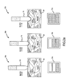
- FIG. 11 a illustrates a schematic of one embodiment of an ablation system that uses two power sources operating at different frequencies, where only one of these power sources is interconnected with the ablation electrode at any one time, and where one of these power sources is used for assessing a coupling between an electrode and tissue.
- FIG. 11 b illustrates a schematic of one embodiment of an ablation system that uses two power sources operating at different frequencies, where both power sources are always interconnected with the ablation electrode, and where one of these power sources is used for assessing a coupling between an electrode and tissue.
- FIG. 11 c illustrates a schematic of one embodiment of an ablation system that uses two power sources operating at least generally at the same frequency, where only one of these power sources is interconnected with the ablation electrode at any one time, and where each of these power sources may be used for assessing a coupling between an electrode and tissue.
- FIG. 12 a illustrates one embodiment of a system for assessing a coupling between an electrode and tissue.
- FIG. 12 b illustrates one embodiment of a protocol that may be used to assess a coupling between an electrode and tissue based upon identifying a baseline coupling condition.
- FIG. 12 c illustrates one embodiment of a protocol that may be used to assess a coupling between an electrode and tissue based upon identifying a target frequency.
- tissue ablation system of the present invention provides a number of advantages, including, for example, the ability to apply a reasonable amount of ablative energy to a target tissue while mitigating electrode-tissue contact and coupling problems.
- the invention also facilitates enhanced tissue contact and electrical coupling in difficult environments (e.g., during lesion formation on a surface inside a beating heart).
- FIG. 1 is a diagrammatic illustration of an exemplary electrode catheter system 10 which may be implemented to assess electrode-tissue contact during a tissue ablation procedure for a patient 12 .
- Catheter system 10 may include an electrode catheter 14 , which may be inserted into the patient 12 , e.g., for forming ablative lesions inside the patient's heart 16 .
- a user e.g., the patient's physician or a technician
- the user guided by a real-time fluoroscopy imaging device (not shown), moves the electrode catheter 14 into the patient's heart 16 (as shown in more detail in FIG. 1 a ).
- electrodes 20 at the tip of the electrode catheter 14 may be implemented to electrically map the myocardium 22 (i.e., muscular tissue in the heart wall) and locate a target tissue 24 .
- the user After locating the target tissue 24 , the user must move the electrode catheter 14 into contact and electrically couple the catheter electrode 14 with the target tissue 24 before applying ablative energy to form an ablative lesion or lesions.
- the electrode-tissue contact refers to the condition when the catheter electrode 14 physically touches the target tissue 24 thereby causing a mechanical coupling between the catheter electrode 14 and the target tissue 24 .
- Electrical coupling refers to the condition when a sufficient portion of electrical energy passes from the catheter electrode 14 to the target tissue 24 so as to allow efficient lesion creation during ablation.
- electrical coupling includes mechanical contact. That is, mechanical contact is a subset of electrical coupling.
- the catheter electrode may be substantially electrically coupled with the target tissue without being in mechanical contact, but not vice-versa. In other words, if the catheter electrode is in mechanical contact, it is also electrically coupled.
- the range or sensitivity of electrical coupling changes for tissues with different electrical properties. For example, the range of electrical coupling for electrically conductive myocardial tissue is different from the vessel walls. Likewise, the range or sensitivity of electrical coupling also changes for tissues with different mechanical properties, such as tissue compliance.
- the range of electrical coupling for the relatively more compliant smooth atrial wall is different from the relatively less compliant pectinated myocardial tissue.
- the level of contact and electrical coupling are often critical to form sufficiently deep ablative lesions on the target tissue 24 without damaging surrounding tissue in the heart 16 .
- the catheter system 10 may be implemented to measure impedance at the electrode-tissue interface and assess the level of contact (illustrated by display 11 ) between the electrode catheter 14 and the target tissue 24 , as described in more detail below.
- FIG. 2 a illustrates exemplary levels of electrical contact or coupling between an electrode catheter 14 and a target tissue 24 .
- FIG. 2 b illustrates exemplary levels of mechanical contact or coupling between an electrode catheter 14 and a target tissue 24 .
- Exemplary levels of contact or coupling may include “little or no contact” as illustrated by contact condition 30 a , “light to medium contact” as illustrated by contact condition 30 b , and “hard contact” as illustrated by contact condition 30 c .
- the catheter system 10 may be implemented to display or otherwise output the contact condition for the user, e.g., as illustrated by light arrays 31 a - c corresponding to contact conditions 30 a - c , respectively.
- Contact condition 30 a (“little or no contact”) may be experienced before the electrode catheter 14 comes into contact with the target tissue 24 . Insufficient contact may inhibit or even prevent adequate lesions from being formed when the electrode catheter 14 is operated to apply ablative energy. However, contact condition 30 c (“hard contact”) may result in the formation of lesions which are too deep (e.g., causing perforations in the myocardium 22 ) and/or the destruction of tissue surrounding the target tissue 24 . Accordingly, the user may desire contact condition 30 b (“light to medium contact”).
- contact or coupling conditions 30 a - c in FIG. 2 a - b are shown for purposes of illustration and are not intended to be limiting.
- Other contact or coupling conditions e.g., finer granularity between contact conditions
- the definition of such contact conditions may depend at least to some extent on operating conditions, such as, the type of target tissue, desired depth of the ablation lesion, and operating frequency of the RF radiation, to name only a few examples.
- FIG. 3 is a high-level functional block diagram showing the catheter system 10 in more detail as it may be implemented to assess contact or coupling conditions for the electrode catheter 14 .
- electrode catheter 14 may include a handle portion, a fluoroscopy imaging device, and/or various other controls, to name only a few examples.
- Such components are well understood in the medical devices arts and therefore further discussion herein is not necessary for a complete understanding of the invention.
- Exemplary catheter system 10 may include a generator 40 , such as, e.g., a radio frequency (RF) generator, and a measurement circuit 42 electrically connected to the electrode catheter 14 (as illustrated by wires 44 to the electrode catheter).
- the electrode catheter 14 may also be electrically grounded, e.g., through grounding patch 46 affixed to the patient's arm or chest (as shown in FIG. 1 ).
- Generator 40 may be operated to emit electrical energy (e.g., RF current) near the tip of the electrode catheter 14 . It is noted that although the invention is described herein with reference to RF current, other types of electrical energy may also be used for assessing contact conditions.
- electrical energy e.g., RF current
- generator 40 emits a so-called “pinging” (e.g., low) frequency as the electrode catheter 14 approaches the target tissue 24 .
- the “pinging” frequency may be emitted by the same electrode catheter that is used to apply ablative energy for lesion formation.
- a separate electrode catheter may be used for applying the “pinging” frequency.
- the separate electrode may be in close contact with (or affixed to) the electrode for applying ablative energy so that a contact or coupling condition can be determined for the electrode which will be applying the ablative energy.
- the resulting impedance at the electrode-tissue interface may be measured during contact or coupling assessment (or “pinging”) using a measurement circuit 42 .
- the measurement circuit 42 may be a conventionally available resistance-capacitance-inductance (RCL) meter.
- RCL resistance-capacitance-inductance
- Another exemplary measurement circuit which may be implemented for determining the phase angle component is also described in more detail below with reference to FIG. 5 .
- Still other measurement circuits 42 may be implemented and the invention is not limited to use with any particular type or configuration of measurement circuit.
- the reactance and/or phase angle component of the impedance measurements may be used to determine a contact or coupling condition.
- the contact or coupling condition may then be conveyed to the user in real-time for achieving the desired level of contact or coupling for the ablation procedure.
- the contact or coupling condition may be displayed for the user on a light array (e.g., as illustrated in FIG. 2 a - b ).
- a generator such as generator 40 or a second generator, may be operated to generate ablative (e.g., high frequency) energy for forming an ablative lesion or lesions on the target tissue 24 .
- the same generator 40 may be used to generate electrical energy at various frequencies both for the impedance measurements (e.g., “pinging” frequencies) and for forming the ablative lesion.
- pinging frequencies
- separate generators or generating units may also be implemented without departing from the scope of the invention.
- measurement circuit 42 may be operatively associated with a processor 50 and memory 52 to analyze the measured impedance.
- processor 50 may determine a reactance and/or phase angle component of the impedance measurement, and based on the reactance component and/or phase angle, the processor 50 may determine a corresponding contact or coupling condition for the electrode catheter 14 .
- contact or coupling conditions corresponding to various reactance and/or phase angles may be predetermined, e.g., during testing for any of a wide range of tissue types and at various frequencies.
- the contact or coupling conditions may be stored in memory 52 , e.g., as tables or other suitable data structures.
- the processor 50 may then access the tables in memory 42 and determine a contact or coupling condition corresponding to impedance measurement based on the reactance component and/or phase angle.
- the contact or coupling condition may be output for the user, e.g., at display device 54 .
- catheter system 10 is not limited to use with processor 50 and memory 52 .
- analog circuitry may be implemented for assessing contact conditions based on the impedance measurement and for outputting a corresponding contact condition. Such circuitry may be readily provided by one having ordinary skill in the electronics arts after having become familiar with the teachings herein, and therefore further discussion is not needed.
- display device 54 is not limited to any particular type of device.
- display device 54 may be a computer monitor such as a liquid-crystal display (LCD).
- display device may be implemented as a light array, wherein one or more light emitting diodes (LED) are activated in the light array to indicate a contact condition (e.g., more lights indicating more contact).
- a contact condition e.g., more lights indicating more contact.
- any suitable output device may be implemented for indicating contact conditions to a user, and is not limited to a display device.
- the contact condition may be output to the user as an audio signal or tactile feedback (e.g., vibrations) on the handle of the electrode catheter.
- measurement circuit 42 and/or processor 50 and memory 52 may be provided in a handle portion of the electrode catheter 14 . In another example, at least part of the measurement circuit 42 may be provided elsewhere in the electrode catheter 14 (e.g., in the tip portion).
- processor 50 , memory 52 , and display device 54 may be provided as a separate computing device, such as a personal desktop or laptop computer which may be operatively associated with other components of the catheter system 10 .
- FIG. 4 is a model of the electrode catheter 14 in contact with (or coupled to) target tissue 24 .
- the electrode catheter 14 is electrically connected to the generator 40 (e.g., an RF generator).
- the circuit may be completed through the target tissue 24 , showing that current flows through the blood, myocardium, and other organs to the reference electrode, such as a grounding patch 46 on the patient's body ( FIG. 1 ).
- the generator 40 may be operated to generate electrical energy for emission by the electrode catheter 14 . Emissions are illustrated in FIG. 4 by arrows 60 . Also as described above, generator 40 may emit a “pinging” frequency as the electrode catheter 14 approaches the target tissue 24 for assessing electrode-tissue contact or coupling. In an exemplary embodiment, this “pinging” frequency may be selected such that inductive, capacitive, and resistive effects other than those at the blood-tissue interface do not appreciably affect the impedance measurements.
- capacitive effects of the blood and at the electrode-blood interface were found be minimal or even non-existent at frequencies higher than about 50 kHz.
- Stray inductance e.g., due to the relatively thin catheter wires
- capacitance and resistance at the electrode interface were also found to be minimal or even non-existent at frequencies higher than about 50 kHz.
- resistive effects dominate at the blood-tissue interface for frequencies below 50 kHz because the current flows into the target tissue 24 primarily via the interstitial fluid spaces 23 , and the cell membranes 25 (e.g., bi-lipids or “fat”) act as an insulator.
- the cell membranes 25 e.g., bi-lipids or “fat”
- the cell membranes 25 become conductive, and electrical current penetrates the target tissue 24 through both the interstitial fluid spaces 23 and the cell membranes 25 . Accordingly, the cell membranes act as “capacitors” and the resistive effects are reduced at frequencies above about 50 kHz.
- a presently preferred range for a current of less than 1 mA is a working frequency in the 50-500 kHz range.
- the frequency choice is mostly based on physiological aspect and engineering aspect and is within the purview of one of ordinary skill in the art.
- lower frequencies can introduce measurement errors due to electrode-electrolyte interface.
- the parasitic capacitance can become significant. It is noted, however, that the invention is not limited to use at any particular frequency or range of frequencies.
- the frequency may depend at least to some extent on operational considerations, such as, e.g., the application, the type of target tissue, and the type of electrical energy being used, to name only a few examples.
- the model shown in FIG. 4 may be further expressed as a simplified electrical circuit 62 , as shown in FIG. 4 a .
- generator 40 is represented as an AC source 64 .
- capacitance and resistance at the blood-tissue interface dominate impedance measurements at low frequency operation such as may be used for assessing electrode-tissue contact. Accordingly, other capacitive, inductive, and resistive effects may be ignored and the capacitive-resistive effects at the blood-tissue interface may be represented in circuit 62 by a resistor-capacitor (R-C) circuit 66 .
- R-C resistor-capacitor
- the R-C circuit 66 may include a resistor 68 representing the resistive effects of blood on impedance, in parallel with a resistor 70 and capacitor 72 representing the resistive and capacitive effects of the target tissue 24 on impedance.
- the magnitude of the reactance component responds to both resistive and capacitive effects of the circuit 62 .
- This variation corresponds directly to the level of contact or coupling at the electrode-tissue interface, and therefore may be used to assess the electrode-tissue contact or coupling.
- the impedance is purely resistive and the reactance (X) is close to 0 Ohms.
- the reactance component becomes negative.
- the level of contact or coupling is increased, the reactance component becomes more negative.
- contact or coupling conditions may be determined based on the phase angle. Indeed, determining contact or coupling conditions based on the phase angle may be preferred in some applications because the phase angle is represented as a trigonometric ratio between reactance and resistance. Although the magnitude of the reactance component may be different under varying conditions (e.g., for different patients), the phase angle is a relative measurement which tends to be insensitive to external conditions.
- the phase angle also corresponds directly to the level of contact or coupling at the electrode-tissue interface, and therefore may be used to assess the electrode-tissue contact or coupling.
- the phase angle is close to zero (0).
- the phase angle becomes negative, and the phase angle becomes more negative as the level of contact or coupling is increased.
- Table 1 An example is shown in Table 1 for purposes of illustration.
- phase detection circuit 80 is shown in FIG. 5 .
- Phase detection circuit 80 is shown and described with reference to functional components. It is noted that a particular hardware configuration is not necessary for a full understanding of the invention. Implementation of the phase detection circuit 80 in digital and/or analog hardware and/or software will be readily apparent to those having ordinary skill in the electronics art after becoming familiar with the teachings herein.
- Exemplary phase detection circuit 80 may include a current sensor 82 and voltage sensor 84 for measuring current and voltage at the electrode-tissue interface. The current and voltage measurements may be input to a phase comparator 86 . Phase comparator 86 provides a direct current (DC) output voltage proportional to the difference in phase between the voltage and current measurements.
- DC direct current
- the current sensor 82 may be used to measure the ablation current.
- the sensor can be in series with ablation wire.
- a Coilcraft CST1 current sensing transformer may be placed in series with the ablation wire.
- the current wire can pass through holes of a current sensor, with or without physical connection.
- the voltage between the ablation electrode and the ground patch can be sensed. This voltage can be attenuated so that it can be fed into a phase sensing circuit.
- the phase sensing circuit measures the current and voltage and determines the phase angle between them, which is then correlated to a coupling level. In this way the ablation current can be used to measure the phase angle rather than injecting an additional current for the coupling sensing purpose.
- phase shift circuit 88 may facilitate operation of the phase comparator 86 by “correcting” phase lag between the measured current and the measured voltage.
- output from the phase comparator 86 may be “corrected” by phase adjustment circuit 90 to compensate for external factors, such as the type of grounding patch 46 being used.
- a signal scaling circuit 92 may also be provided to amplify the output (e.g., from milli-volts to volts) for use by various devices (e.g., the processor 50 and display device 54 in FIG. 3 ).
- the measured impedance, and its component's resistance and reactance change with tissue temperature.
- the change due to changes in tissue temperature provides a measure of lesion formation during ablation.
- phase detection circuit 80 shown in FIG. 5 is provided as one example, and is not intended to be limiting. Other implementations may also be readily provided by those having ordinary skill in the electronics arts after becoming familiar with the teachings herein without departing from the scope of the invention.
- FIG. 6 is an exemplary block diagram 100 showing phase angle measurement for sensing contact or coupling.
- FIG. 7 is an exemplary block 200 diagram showing phase angle measurement during ablation with both ablation energy and a contact sensing signal applied to the ablation electrode at the same time.
- FIG. 8 is an exemplary block diagram 300 showing phase angle measurement during ablation with switching between sensing signal and ablation power. It is noted that 200-series and 300-series reference numbers are used in FIG. 7 and FIG. 8 , respectively, to denote similar elements and these elements may not be described again with reference to FIG. 7 and FIG. 8 .
- phase angle may be used to represent the contact or coupling levels because phase angle is a relative term of both resistance and reactance. That is, it provides a 0° base line when the electrode is in contact with blood, and becomes increasingly more negative as more contact or coupling is established. It also minimizes the influence of the catheter, instrumentation, and physiological variables.
- the phase angle measurement may be made by sampling both electrical voltage (V) 102 and current (I) 104 of a load and calculating the lag between those signals as the phase angle.
- a sensing signal 106 is applied between the ablation electrode 108 and a reference electrode 110 .
- This sensing signal 106 can, for example, be between 50 to 500 kHz at a small amplitude ( ⁇ 1 mA).
- Exemplary instruments may be operated as frequencies of, for example but not limited to, 100 kHz, 400 kHz and 485 kHz, depending on the reference electrode configuration. Both current 104 and voltage 102 are sensed. These two signals are transmitted to a phase comparator 112 to calculate phase angle, which corresponds to the contact or coupling condition of the electrode 108 .
- the raw phase angle signal is adjusted in block 114 to compensate for external influence on the phase angle, e.g., caused by the catheter, instrumentation, and physiological variables. It is also conditioned for easy interpretation and interface and then output in block 116 to other equipments for display or further processing.
- the phase compensation may be achieved at the beginning of an ablation procedure.
- the catheter electrode is maneuvered to the middle of the heart chamber (e.g., the right atrium or left atrium) so that the electrode 108 only contacts blood.
- the system measures the phase angle and uses this value as a baseline for zero contact level. This adjustment compensates the fixed phase angles caused by catheter and patient such as catheter wiring, location of the reference electrode and skin or adiposity if external patch is used.
- the user may maneuver the catheter electrode to one or more desired sites to ablate arrhythmic myocardium.
- the phase angle starts to change when the electrode 108 approaches to say within 3 mm from the myocardium and becomes increasingly more negative as more contact or coupling is established.
- the user may judge the quality of electrode contact or coupling before administering the ablation energy based on phase angle output.
- this phase angle value is about ⁇ 3° when a 4 mm ablation electrode actually contacts the myocardium. It is noted that there are at least two methods to measure phase angle during ablation, as described in more detail now with reference to FIG. 7 and FIG. 8 .
- ablation power 218 is applied to the electrode 208 while the sensing signal 206 is applied as well.
- the ablation and contact sensing operate at different frequencies. Accordingly, with filtering, the phase angle can be measured during ablation without disturbing the ablation of the myocardium.
- Another option is to switch the phase measurement between the sensing signal 306 and ablation power 318 , as indicated by switch 320 in FIG. 8 .
- the ablation power 318 is switched off during approach, the small amplitude sensing signal 306 is switched on and used to measure phase angle for sensing contact or coupling.
- the ablation power 318 is switched on for the ablation procedure, the voltage and current of the large amplitude ablation power 318 are sensed and used as the contact or coupling indicator during ablation.
- FIG. 9 a illustrates one embodiment of an electrode coupling assessment protocol 400 (hereafter “assessment protocol 400 ”) that may be used to assess the coupling of an electrode (e.g., a catheter electrode) with any appropriate tissue, where this assessment is phase angle based. Therefore, the protocol 400 may be used in relation to the embodiments discussed above in relation to FIGS. 6-8 .
- “coupling” may include an electrical coupling of an electrode with a target tissue, a mechanical coupling between an electrode and the target tissue, or both.
- Step 402 of the assessment protocol 400 of FIG. 9 a is directed to sending an electrical signal to an electrode. Typically this will be after the electrode has been positioned at least in the general vicinity of the target tissue (e.g., within a heart chamber, such as the left atrium).
- a phase angle is thereafter determined at step 404 , and the electrode coupling is thereafter assessed at step 408 based upon this phase angle.
- the electrode coupling assessment from step 408 may be categorized through execution of step 410 . However, the categorization of step 410 may not be required in all instances. In any case, the result of the assessment from step 408 is output pursuant to step 412 .
- the electrical signal that is sent pursuant to step 402 of the protocol 400 may be at any appropriate frequency. However, only a single frequency is required to make the assessment for purposes of the protocol 400 .
- the phase angle associated with step 404 may be the phase angle of the impedance. This phase angle may be determined in any appropriate manner, for instance using a phase sensing circuit of any appropriate configuration. In one embodiment and using the electrical signal associated with step 402 , the phase angle is determined by measuring the current at the electrode, measuring the voltage between the electrode and another electrode (e.g., a return electrode), and then determining the phase angle between these current and voltage measurements. Another option would be to measure/determine the reactance and impedance in an appropriate manner, and to then determine the phase angle from these values (e.g., the sine of the phase angle being the ratio of the reactance to the impedance).
- the phase angle may be determined using an RCL meter or a phase detection circuit (e.g., having an oscillator, multiplexer, filter, phase detection circuit), and may be referred to as a phase module.
- This phase module (measurement and/or detection) may be disposed at any appropriate location, such as by being incorporated into or embedded in the catheter handle set, by being in the form of a standalone unit between the ablation catheter and the power generator, by being incorporated into or embedded in the power generator, by being incorporated into an electrophysiology or EP mapping system, or by being part of an electrophysiology recording system.
- Assessment of the coupling of the electrode with the tissue may be undertaken in any appropriate manner.
- the phase angle determined through step 404 may be compared with one or more benchmark phase angle values (e.g., using a phase angle comparator). These benchmark phase angle values may be determined/set in any appropriate manner, for instance empirically. These benchmark phase angle values may be stored in an appropriate data structure, for instance on a computer-readable data storage medium, or otherwise may be made available to a phase angle comparator.
- the phase angle decreases as more electrode-tissue (e.g., myocardium) coupling exists.
- phase angle values there may be one or more benchmark phase angle values (e.g., a single benchmark phase angle value or a range of benchmark phase angle values) for one or more of the following conditions for purposes of the categorization of step 410 of the assessment protocol 400 of FIG. 9 a: 1) insufficient electrode coupling (e.g., an electrode coupling where the associated phase angle being less than “A” is equated with an insufficient electrode coupling); 2) sufficient electrode coupling (e.g., an electrode coupling with an associated phase angle greater than “A” and less than “B” being equated with a sufficient electrode coupling); and 3) elevated or excessive electrode coupling (e.g., an electrode coupling where the associated phase angle being greater than “B” is equated with an elevated or excessive electrode coupling).
- insufficient electrode coupling e.g., an electrode coupling where the associated phase angle being less than “A” is equated with an insufficient electrode coupling
- sufficient electrode coupling e.g., an electrode coupling with an associated phase angle greater
- an “elevated” or “excessive” electrode coupling may be elevated/excessive in relation to the electrical coupling, the mechanical coupling, or both (the coupling between the electrode and the target tissue).
- an elevated/excessive or hard electrode coupling means an elevated/excessive mechanical contact between the electrode and the target tissue. It may be desirable to know when an elevated or excessive mechanical contact exists between the electrode and tissue for a variety of reasons. For instance, it may be desirable to avoid an elevated or excessive mechanical contact between the electrode and the target tissue (e.g., to reduce the likelihood of directing the electrode through a tissue wall, membrane, or the like).
- the result of the assessment of step 408 may be output in any appropriate manner pursuant to step 412 of the electrode coupling assessment protocol 400 of FIG. 9 a .
- Any appropriate output may be utilized, for instance visually (e.g., a bar graph or any other appropriate display at any appropriate location or combination of locations), audibly (e.g., an alarm), physically (e.g., by vibrating a handle being held by a physician that is performing an electrode-based procedure, and as discussed in more detail herein), or any combination thereof.
- a single output may be provided.
- a combination of two or more outputs may also be utilized.
- One or more outputs may be issued to a single location or to multiple locations.
- FIG. 9 b illustrates one embodiment of an electrode coupling assessment protocol 400 ′ that may be used to assess the coupling of an electrode (e.g., a catheter electrode) with any appropriate tissue, where this assessment is reactance based.
- an electrode e.g., a catheter electrode
- FIG. 9 b illustrates one embodiment of an electrode coupling assessment protocol 400 ′ that may be used to assess the coupling of an electrode (e.g., a catheter electrode) with any appropriate tissue, where this assessment is reactance based.
- the protocol 400 ′ is a variation of the protocol 400 of FIG. 9 a
- a “single prime” designation is used in relation the reference numerals that identify the individual steps of the protocol 400 ′ of FIG. 9 b.
- Step 402 ′ of the assessment protocol 400 ′ of FIG. 9 b is directed to sending an electrical signal. Only a single frequency is required for the protocol 400 ′ to provide its assessment. That is, the electrode coupling assessment may be provided using a single frequency in the case of the assessment protocol 400 ′. Typically this will be after the electrode has been positioned at least in the general vicinity of the target tissue (e.g., within a heart chamber). A reactance of the electrical circuit that includes the electrode and the target tissue is thereafter determined at step 404 ′. This reactance may be determined in any appropriate manner.
- the phase angle may be measured (e.g., in accordance with the foregoing), the impedance may be measured, and the reactance may be calculated from these two values (e.g., the sine of the phase angle is equal to the ratio of the reactance to the impedance).
- Another option for determining the reactance would be to determine the phase or frequency response of a pulse wave.
- the electrode coupling is assessed at step 408 ′ of the protocol 400 ′ based upon the above-noted reactance.
- This electrode coupling from step 408 ′ may be categorized through execution of step 410 ′. However, the categorization of step 410 ′ may not be required in all instances. In any case, the result of the assessment is output pursuant to step 412 ′.
- Step 412 ′ may correspond with step 412 of the electrode coupling assessment protocol 400 of FIG. 9 a.
- Assessment of the electrode coupling with the tissue may be undertaken in any appropriate manner.
- the reactance determined through step 404 ′ may be compared with one or more benchmark reactance values (e.g., using a reactance comparator). These benchmark reactance values may be determined/set in any appropriate manner, for instance empirically. These benchmark reactance values may be stored in an appropriate data structure, for instance a computer—readable data storage medium, or otherwise may be made available to a reactance comparator.
- the reactance decreases as more electrode-tissue (e.g., myocardium) coupling exists.
- step 410 ′ There may be one or more benchmark reactance values (e.g., a single benchmark reactance value or a range of benchmark reactance values) for one or more of the following conditions for purposes of the categorization of step 410 ′: 1) insufficient electrode coupling (e.g., an electrode coupling where the associated reactance being less than “A” is equated with insufficient electrode coupling); 2) sufficient electrode coupling (e.g., an electrode coupling with an associated reactance greater than “A” and less than “B” being equated with a sufficient electrode coupling); and 3) elevated or excessive electrode coupling (e.g., an electrode coupling where the associated reactance being greater than “B” is equated with an elevated or excessive electrode coupling).
- One embodiment equates the following reactance values for the noted conditions: insufficient electrode coupling: X> ⁇ 5 sufficient electrode coupling: ⁇ 5> X> ⁇ 15 elevated/excessive electrode coupling: X ⁇ 15
- FIG. 9 c illustrates such an embodiment of an electrode coupling assessment protocol 480 —a protocol 480 that may be used to assess the coupling of an electrode (e.g., a catheter electrode) with any appropriate tissue.
- Step 482 of the assessment protocol 480 is directed to sending an electrical signal to an electrode at a certain frequency. At least one electrical parameter is measured at step 484 .
- impedance components ratio means any term that is a ratio of two individual components of the impedance, such as the phase angle (the tangent of the phase angle being equal to the ratio of reactance to resistance).
- the impedance components ratio may be determined in any appropriate manner, such as by simply measuring a phase angle.
- Other ways for determining the impedance components ratio include without limitation determining a resistance and reactance at the frequency encompassed by step 482 , and calculating the impedance components ratio from these two parameters. Using a ratio of two components that relate to impedance may provide less sensitivity to changes from tissue to tissue for an electrode coupling assessment—an assessment of the coupling between an electrode and the target tissue.
- the electrode coupling is assessed at step 488 of the protocol 480 .
- This electrode coupling from step 488 may be categorized through execution of step 490 , where step 490 may be in accordance with step 410 of the electrode coupling assessment protocol 400 discussed above in relation to FIG. 9 a . As such, the categorization of step 490 may not be required in all instances.
- the result of the assessment is output pursuant to step 492 .
- Step 492 may be in accordance step 412 of the electrode coupling assessment protocol 400 discussed above in relation to FIG. 9 a.
- Each of the protocols of FIGS. 9 a - c encompasses the electrode coupling being a mechanical coupling between the electrode and the target tissue (i.e., physical contact), as well as an electrical coupling (e.g., a condition when a sufficient portion of the electrical energy passes from the electrode to the target tissue). Any time there is a mechanical coupling, there is an electrical coupling. The reverse, however, is not true. There may be an electrical coupling without the electrode being in contact with the target tissue.
- FIG. 10 illustrates a representative example of where there is an electrical coupling without having mechanical contact between an electrode 414 and the target tissue 416 .
- each of the protocols of FIGS. 9 a - c may provide an indication of electrical coupling without requiring mechanical contact between the electrode and the target tissue.
- FIGS. 11 a - c schematically present various configurations that may be used in relation to providing an electrode coupling assessment. Although each of these systems will be discussed in relation to an ablation electrode, this electrode coupling assessment may be used for any appropriate application where an electrode provides any appropriate function or combination of functions. Each of the systems of FIGS. 11 a - c may be used to provide the assessment protocols discussed above in relation to FIGS. 9 a - c .
- FIG. 11 a illustrates an ablation system 420 that includes an ablation power source 424 , an ablation electrode 422 , and a return electrode 426 .
- Any appropriate frequency may be used by the ablation power source 424 .
- Each of the ablation electrode 422 and return electrode 426 may be of any appropriate size, shape, and/or configuration.
- the ablation electrode 422 will be in the form of a catheter electrode that is disposed within the patient's body.
- the return electrode 426 may be disposed at any appropriate location (e.g., a ground patch disposed on the skin of a patient; a catheter electrode disposed within the body of a patient).
- Additional components of the ablation system 420 include an electrode coupling assessment power source 428 (hereafter the “assessment power source 428 ”), an assessment return electrode 430 , and an electrode coupling assessment module 432 (hereafter the “assessment module 432 ”). Any appropriate frequency may be used by the assessment power source 428 .
- the ablation power source 424 will also use a significantly higher current than the assessment power source 428 .
- the assessment return electrode 430 may be of any appropriate size, shape, and/or configuration, and may be disposed at any appropriate location.
- One embodiment has the return electrode 426 and the assessment return electrode 430 being in the form of separate structures that are disposed at different locations.
- Another embodiment has the functionality of the return electrode 426 and the functionality of the assessment return electrode 430 be provided by a single structure (a single unit that functions as both a return electrode 426 and as an assessment return electrode 430 ).
- the ablation electrode 422 either receives power from the ablation power source 424 or the assessment power source 428 , depending upon the position of a switch 434 for the ablation system 420 . That is, ablation operations and electrode coupling assessment operations may not be simultaneously conducted in the case of the ablation system 420 of FIG. 11 a .
- the switch 434 is of course positioned to receive power from the assessment power source 428 . This allows the assessment module 432 to assess the coupling between the ablation electrode 422 and the target tissue.
- any appropriate configuration may be utilized by the assessment module 432 to provides its electrode coupling assessment function, including without limitation the various configurations addressed herein (e.g., assessment based upon phase angle comparisons; assessment based upon reactance comparisons; assessment based upon impedance components ratio comparisons; assessment based upon identifying the frequency associated with a 0° phase frequency or a 0 inductance frequency as will be discussed below in relation to FIGS. 12 a - b ).
- the assessment module 432 may provide the electrode coupling assessment using any of the protocols of FIGS. 9 a - c from a single frequency.
- FIG. 11 b illustrates an ablation system 440 that includes an ablation power source 444 , an ablation electrode 442 , and a return electrode 446 .
- Any appropriate frequency may be used by the ablation power source 444 .
- Each of the ablation electrode 442 and return electrode 446 may be of any appropriate size, shape, and/or configuration.
- the ablation electrode 442 will be in the form of a catheter electrode that is disposed within the patient's body.
- the return electrode 446 may be disposed at any appropriate location (e.g., a ground patch disposed on the skin of a patient; a catheter electrode disposed within the body of a patient).
- Additional components of the ablation system 440 include an electrode coupling assessment power source 448 (hereafter the “assessment power source 448 ”), an assessment return electrode 450 , and an electrode coupling assessment module 452 (hereafter the “assessment module 452 ”). Any appropriate frequency may be used by the assessment power source 448 .
- the ablation power source 444 and the assessment power source 448 operate at different frequencies in the case of the ablation system 440 in order to accommodate the simultaneous execution of ablation and electrode coupling assessment operations.
- typically the ablation power source 444 will also use a significantly higher current than the assessment power source 448 .
- the assessment return electrode 450 may be of any appropriate size, shape, and/or configuration, and may be disposed at any appropriate location.
- One embodiment has the return electrode 446 and the assessment return electrode 450 being in the form of separate structures that are disposed at different locations.
- Another embodiment has the functionality of the return electrode 446 and the functionality of the assessment return electrode 450 be provided by a single structure (a single unit that functions as both a return electrode 446 and as an assessment return electrode 450 ).
- the ablation electrode 442 may simultaneously receive power from the ablation power source 444 and the assessment power source 448 . That is, ablation operations and electrode coupling assessment operations may be simultaneously executed in the case of the ablation system 440 of FIG. 11 b . In this regard, the ablation power source 444 and the assessment power source 448 again will operate at different frequencies.
- the assessment module 452 may provide the electrode coupling assessment using any of the protocols of FIGS. 9 a - c from a single frequency. In any case, the assessment module 452 assesses the coupling between the ablation electrode 442 and the target tissue.
- the discussion presented above with regard to the assessment module 432 for the ablation system 420 of FIG. 11 a is equally applicable to the assessment module 452 for the ablation system 440 of FIG. 11 b.
- FIG. 11 c illustrates an ablation system 460 that includes an ablation power source 464 , an ablation electrode 462 , and a return electrode 466 .
- Any appropriate frequency may be used by the ablation power source 464 .
- Each of the ablation electrode 462 and return electrode 466 may be of any appropriate size, shape, and/or configuration.
- the ablation electrode 462 will be in the form of a catheter electrode that is disposed within the patient's body.
- the return electrode 466 may be disposed at any appropriate location (e.g., a ground patch disposed on the skin of a patient; a catheter electrode disposed within the body of a patient).
- Additional components of the ablation system 460 include an electrode coupling assessment power source 468 (hereafter the “assessment power source 468 ”). Any appropriate frequency may be used by the assessment power source 468 . Typically, the ablation power source 464 will also use a significantly higher current than the assessment power source 468 .
- the ablation system 460 further includes a pair of electrode coupling assessment modules 472 a , 472 b (hereafter the “assessment module 472 a ” and “the assessment module 472 b ”).
- the assessment module 472 a is associated with the assessment power source 468
- the assessment module 472 b is associated with the ablation power source 464 .
- Both ablation operations and electrode coupling assessment operations utilize the return electrode 466 in the illustrated embodiment, although it may be possible to utilize separate return electrodes as in the case of the embodiments of FIGS. 11 a and 11 b discussed above.
- the ablation electrode 462 either receives power from the ablation power source 464 or the assessment power source 468 , depending upon the position of a switch 474 for the ablation system 460 .
- electrode coupling assessment operations may be executed regardless of the position of the switch 474 , unlike the embodiment of FIG. 11 a .
- the assessment module 472 a is used to assess the coupling between the ablation electrode 462 and the target tissue.
- the assessment module 472 b is used to assess the coupling between the ablation electrode 462 and the target tissue.
- the assessment modules 427 a , 472 b may each provide an electrode coupling assessment using any of the protocols of FIGS. 9 a - c from a single frequency.
- each of the assessment module 472 a , 472 b may be utilized by each of the assessment module 472 a , 472 b to provide their respective electrode coupling assessment functions, including without limitation the various configurations addressed herein.
- the discussion presented above with regard to the assessment module 432 for the ablation system 420 of FIG. 11 a is equally applicable to the assessment modules 472 a , 472 b for the ablation system 460 of FIG. 11 c .
- the assessment modules 472 a , 472 b will be of the same configuration for assessing electrode coupling, although such may not be required in all instances.
- the ablation power source 464 and the assessment power source 468 will typically operate at the same frequency.
- the ablation system 460 accommodates the assessment of electrode coupling prior to initiating ablation operations (e.g., using an assessment current and the assessment module 472 a ), and further accommodates the assessment of electrode coupling during ablation operations (e.g., using the actual ablation current versus a smaller current, and using the assessment module 472 b ).
- the ablation system 440 of FIG. 11 b also accommodates the assessment of electrode coupling during ablation operations, but it uses a separate assessment current versus the actual ablation current.
- FIG. 1 a illustrates one embodiment where the return electrode used by the assessment module and the return electrode that cooperates with the ablation electrode to provide electrical energy to the tissue for providing one or more desired functions are integrated into a common structure.
- an ablation electrode 20 e.g., a catheter electrode
- a chamber of the heart 16 e.g., the left atrium
- a return electrode 20 a (e.g., a catheter electrode) is also disposed in the same chamber of the heart 16 and may be used by each of the assessment modules of FIGS. 11 a - c (to assess coupling of the ablation electrode 20 with the target tissue 24 ) and the ablation electrode 20 (to deliver electrical energy to the target tissue 24 to provide a desired medical function). Therefore, the ablation electrode 20 and the return electrode 20 a may be associated with different catheters, and thereby may be independently moved or manipulated. In one embodiment, the return electrode 20 a has a larger surface area than the ablation electrode 20 . Each of the ablation electrode 20 and the return electrode 20 a have electrode tips that are spaced from each other.
- FIG. 1 a provides two electrodes 20 , 20 a in a common heart chamber. Another option would be to have two or more electrodes be associated with a common catheter, but where the catheter has two separated distal portions each with an electrode on a separate electrode tip on a distal end thereof such that the electrode tips are spaced from each other.
- FIGS. 12 a - b presents a schematic of an electrode coupling assessment system 500 which includes a variable frequency source 502 , an electrical parameter measurement module 504 , an electrode coupling assessment module 506 , and an electrode 508 that is to be coupled with tissue 510 to provide a desired function or combination of functions (e.g., ablation).
- the return electrode is not illustrated in FIG. 12 a , but may be of any appropriate type and disposed at any appropriate location.
- variable frequency source 502 provides an electrical signal to the electrode 508 for purposes of transmitting electrical energy to the tissue 510 .
- the electrical parameter measurement module 504 may be of any appropriate type and/or configuration, measures one or more electrical parameters, and provides information used by the electrode coupling assessment module 506 .
- the electrode coupling assessment module 506 assesses the coupling between the electrode 508 and the tissue 510 .
- FIG. 12 b presents one embodiment of an electrode coupling protocol 520 that may be used by the electrode coupling assessment module 506 of FIG. 12 a .
- One or more electrical signals are sent to the electrode 508 through execution of step 524 .
- a baseline coupling condition can be assessed.
- the baseline coupling condition can be defined pursuant to steps 524 - 528 of protocol 520 .
- the term “baseline coupling condition” encompasses a zeroed phase angle or zeroed reactance at a desired frequency in a medium (e.g., blood).
- the baseline coupling condition is established. For example, the physician can activate an input device to indicate the establishment of the baseline coupling condition.
- protocol 520 adjusts to the baseline coupling condition in step 528 by correcting the phase angle or the reactance to zero.
- the value(s) of the baseline coupling condition established in step 526 may be stored and used to determine an electrode coupling condition relative to such a baseline coupling condition.
- the baseline coupling condition may be determined by comparing the determined phase angle with one or more predetermined benchmark values.
- These benchmark values may be determined/set in any appropriate manner, for instance empirically through in vitro, ex vivo, or in vivo studies. These benchmark values may be stored in an appropriate data structure, for instance on a computer-readable data storage medium, or otherwise may be made available to a phase comparator.
- the electrode coupling may be assessed pursuant to step 532 of the protocol 520 using the baseline coupling condition from step 528 .
- One or more electrical parameters may be determined in any appropriate manner and compared with the corresponding value of the baseline coupling condition from step 528 .
- the following categories may be provided: 1) insufficient electrode coupling (e.g., an electrode coupling where the value(s) associated with a baseline coupling condition being less than “A” is equated with insufficient electrode coupling); 2) sufficient electrode coupling (e.g., an electrode coupling where the value(s) associated with a baseline coupling condition greater than “A” and less than “B” is equated with a sufficient electrode coupling); and 3) elevated or excessive electrode coupling (e.g., an electrode coupling where the value(s) associated with a baseline coupling condition being greater than “B” is equated with an elevated or excessive electrode coupling).
- insufficient electrode coupling e.g., an electrode coupling where the value(s) associated with a baseline coupling
- the electrical coupling is measured as a function of a “target frequency”—a frequency that corresponds to a preset value for an electrical parameter (e.g., a preset reactance or a phase angle value).
- FIG. 12 c presents one embodiment of an electrode coupling protocol 620 that may be used by the electrode coupling assessment module 506 of FIG. 12 a . Electrical signals are sent to the electrode 508 through execution of step 624 . The electrical signals are sent at varying frequencies. At each frequency sent, step 626 measures the reactance and/or phase. Step 628 compares the measured reactance or phase with a preset value.
- the frequency at which the reactance or phase matches the preset value is the “target frequency.” Any appropriate value may be used for the preset value for purposes of step 628 , including a positive value, zero, or a negative value (e.g., a zero phase angle, such that the target frequency may be referred to as a 0° phase frequency; or a zero inductance, such that the target condition frequency may be referred to as a 0 inductance frequency).
- Step 630 the coupling of the electrode 508 with the tissue 510 is assessed using the information provided by step 628 , and the result of this assessment is output pursuant to step 636 of the protocol 620 .
- Step 636 may be in accordance with step 412 of the protocol discussed above in relation to FIG. 9 a.
- the target frequency from step 628 may be compared with one or more benchmark frequency values (e.g., using a comparator). These benchmark frequency values may be determined/set in any appropriate manner. The values can be predetermined, for instance empirically through in vitro, ex vivo, or in vivo studies. These benchmark frequency values may be stored in an appropriate data structure, for instance on a computer-readable data storage medium. The benchmark frequency values can also be determined during the procedure by a physician. For example, a determination can be made when the electrode is in the desired medium, e.g., the blood. At that point the physician can activate an input device to set the benchmark value for the existing coupling relevant condition.
- a physician can activate an input device to set the benchmark value for the existing coupling relevant condition.
- benchmark frequency values e.g., a single benchmark frequency value or a range of benchmark frequency values
- insufficient electrode coupling e.g., an electrode coupling where the target frequency being less than “A” is equated with insufficient electrode coupling
- sufficient electrode coupling e.g., an electrode coupling where the target frequency is greater than “A” and less than “B” is equated with sufficient electrode coupling
- excessive electrode coupling e.g., an electrode coupling where the target frequency being greater than “B” is equated with an excessive electrode coupling.
- One embodiment equates the following target frequency values for the noted conditions (where F t is the target frequency for the noted condition): insufficient electrode coupling: F t ⁇ 120 kHz sufficient electrode coupling: 120 kHz ⁇ F t ⁇ 400 kHz elevated/excessive electrode coupling: F t >400 kHz
- the protocol 620 of FIG. 12 c may be implemented in any appropriate manner.
- the impedance may be monitored to obtain the target phase frequency by sweeping the signal frequency (e.g., in accordance with the system 500 of FIG. 12 a ).
- This frequency sweep could be provided between two appropriate values (e.g., 50 kHz and 1 MHz) and using any appropriate incremental change between these values for the sweep (e.g., 10-20 kHz increments).
- This approach uses what may be referred to as frequency switching, which involves measuring the impedance one frequency at a time and rotating the frequencies by a frequency synthesizer or the like.
- Another approach would be to combine multiple frequencies together, and to determine the impedance at each of the individual frequencies from the combined signal through filtering. It should be appreciated that it may be such that interpolation will be required to determine the frequency associated with the target frequency condition in some cases (e.g., where the frequency associated with the target frequency condition is determined to exist between two frequencies used by the protocol 620 ).
Abstract
Description
Z=R+jX
where:
-
- R is resistance from the blood and/or tissue;
- j an imaginary number indicating the term has a phase angle of +90 degrees; and
- X is reactance from both capacitance and inductance.
Z=|Z|∠φ
where:
-
- |Z| is the magnitude of the impedance; and
- φ is the phase angle.
| TABLE 1 |
| Phase Angle Relation to Contact Conditions |
| Phase Angle | Contact Condition | ||
| φ > −3° | little or no contact or coupling | ||
| −3° < φ < −7° | medium contact or coupling | ||
| −7°< φ < −10° | high contact or coupling | ||
| φ < −10° | excessive contact or coupling | ||
insufficient electrode coupling: Φ>−5°
sufficient electrode coupling: −5°>Φ>−10°
elevated/excessive electrode coupling: Φ<−10°
insufficient electrode coupling: X>−5
sufficient electrode coupling: −5>X>−15
elevated/excessive electrode coupling: X<−15
insufficient electrode coupling: Ft<120 kHz
sufficient electrode coupling: 120 kHz<Ft<400 kHz
elevated/excessive electrode coupling: Ft>400 kHz
Claims (13)
Priority Applications (1)
| Application Number | Priority Date | Filing Date | Title |
|---|---|---|---|
| US12/095,685 US8998890B2 (en) | 2005-12-06 | 2006-12-06 | Assessment of electrode coupling for tissue ablation |
Applications Claiming Priority (4)
| Application Number | Priority Date | Filing Date | Title |
|---|---|---|---|
| US74823405P | 2005-12-06 | 2005-12-06 | |
| US82929806P | 2006-10-12 | 2006-10-12 | |
| US12/095,685 US8998890B2 (en) | 2005-12-06 | 2006-12-06 | Assessment of electrode coupling for tissue ablation |
| PCT/US2006/046816 WO2007070361A2 (en) | 2005-12-06 | 2006-12-06 | Assessment of electrode coupling for tissue ablation |
Publications (2)
| Publication Number | Publication Date |
|---|---|
| US20100286690A1 US20100286690A1 (en) | 2010-11-11 |
| US8998890B2 true US8998890B2 (en) | 2015-04-07 |
Family
ID=38163417
Family Applications (1)
| Application Number | Title | Priority Date | Filing Date |
|---|---|---|---|
| US12/095,685 Active 2029-12-22 US8998890B2 (en) | 2005-12-06 | 2006-12-06 | Assessment of electrode coupling for tissue ablation |
Country Status (2)
| Country | Link |
|---|---|
| US (1) | US8998890B2 (en) |
| WO (1) | WO2007070361A2 (en) |
Cited By (22)
| Publication number | Priority date | Publication date | Assignee | Title |
|---|---|---|---|---|
| US20110178508A1 (en) * | 2010-01-15 | 2011-07-21 | Ullrich Christopher J | Systems and Methods for Minimally Invasive Surgical Tools with Haptic Feedback |
| US20150327811A1 (en) * | 2013-03-04 | 2015-11-19 | Mortara Instrument, Inc. | Impedance measurement system |
| US9510905B2 (en) | 2014-11-19 | 2016-12-06 | Advanced Cardiac Therapeutics, Inc. | Systems and methods for high-resolution mapping of tissue |
| US9517103B2 (en) | 2014-11-19 | 2016-12-13 | Advanced Cardiac Therapeutics, Inc. | Medical instruments with multiple temperature sensors |
| US9603659B2 (en) | 2011-09-14 | 2017-03-28 | Boston Scientific Scimed Inc. | Ablation device with ionically conductive balloon |
| US9636164B2 (en) | 2015-03-25 | 2017-05-02 | Advanced Cardiac Therapeutics, Inc. | Contact sensing systems and methods |
| US9743854B2 (en) | 2014-12-18 | 2017-08-29 | Boston Scientific Scimed, Inc. | Real-time morphology analysis for lesion assessment |
| US9757191B2 (en) | 2012-01-10 | 2017-09-12 | Boston Scientific Scimed, Inc. | Electrophysiology system and methods |
| US9993178B2 (en) | 2016-03-15 | 2018-06-12 | Epix Therapeutics, Inc. | Methods of determining catheter orientation |
| US10076238B2 (en) | 2011-09-22 | 2018-09-18 | The George Washington University | Systems and methods for visualizing ablated tissue |
| US10143517B2 (en) | 2014-11-03 | 2018-12-04 | LuxCath, LLC | Systems and methods for assessment of contact quality |
| US10166062B2 (en) | 2014-11-19 | 2019-01-01 | Epix Therapeutics, Inc. | High-resolution mapping of tissue with pacing |
| US10172536B2 (en) | 2012-12-20 | 2019-01-08 | Boston Scientific Scimed, Inc. | Real-time feedback for electrode contact during mapping |
| US10356001B1 (en) | 2018-05-09 | 2019-07-16 | Biosig Technologies, Inc. | Systems and methods to visually align signals using delay |
| US10524684B2 (en) | 2014-10-13 | 2020-01-07 | Boston Scientific Scimed Inc | Tissue diagnosis and treatment using mini-electrodes |
| US10603105B2 (en) | 2014-10-24 | 2020-03-31 | Boston Scientific Scimed Inc | Medical devices with a flexible electrode assembly coupled to an ablation tip |
| US10722301B2 (en) | 2014-11-03 | 2020-07-28 | The George Washington University | Systems and methods for lesion assessment |
| US10736512B2 (en) | 2011-09-22 | 2020-08-11 | The George Washington University | Systems and methods for visualizing ablated tissue |
| US10779904B2 (en) | 2015-07-19 | 2020-09-22 | 460Medical, Inc. | Systems and methods for lesion formation and assessment |
| US10888373B2 (en) | 2017-04-27 | 2021-01-12 | Epix Therapeutics, Inc. | Contact assessment between an ablation catheter and tissue |
| US11457817B2 (en) | 2013-11-20 | 2022-10-04 | The George Washington University | Systems and methods for hyperspectral analysis of cardiac tissue |
| US11684416B2 (en) | 2009-02-11 | 2023-06-27 | Boston Scientific Scimed, Inc. | Insulated ablation catheter devices and methods of use |
Families Citing this family (36)
| Publication number | Priority date | Publication date | Assignee | Title |
|---|---|---|---|---|
| US6994706B2 (en) | 2001-08-13 | 2006-02-07 | Minnesota Medical Physics, Llc | Apparatus and method for treatment of benign prostatic hyperplasia |
| US7041096B2 (en) * | 2002-10-24 | 2006-05-09 | Synergetics Usa, Inc. | Electrosurgical generator apparatus |
| US8641704B2 (en) * | 2007-05-11 | 2014-02-04 | Medtronic Ablation Frontiers Llc | Ablation therapy system and method for treating continuous atrial fibrillation |
| US10272178B2 (en) | 2008-04-29 | 2019-04-30 | Virginia Tech Intellectual Properties Inc. | Methods for blood-brain barrier disruption using electrical energy |
| US11272979B2 (en) | 2008-04-29 | 2022-03-15 | Virginia Tech Intellectual Properties, Inc. | System and method for estimating tissue heating of a target ablation zone for electrical-energy based therapies |
| US10245098B2 (en) | 2008-04-29 | 2019-04-02 | Virginia Tech Intellectual Properties, Inc. | Acute blood-brain barrier disruption using electrical energy based therapy |
| US9198733B2 (en) | 2008-04-29 | 2015-12-01 | Virginia Tech Intellectual Properties, Inc. | Treatment planning for electroporation-based therapies |
| US8992517B2 (en) | 2008-04-29 | 2015-03-31 | Virginia Tech Intellectual Properties Inc. | Irreversible electroporation to treat aberrant cell masses |
| US10117707B2 (en) | 2008-04-29 | 2018-11-06 | Virginia Tech Intellectual Properties, Inc. | System and method for estimating tissue heating of a target ablation zone for electrical-energy based therapies |
| US9867652B2 (en) | 2008-04-29 | 2018-01-16 | Virginia Tech Intellectual Properties, Inc. | Irreversible electroporation using tissue vasculature to treat aberrant cell masses or create tissue scaffolds |
| US10448989B2 (en) | 2009-04-09 | 2019-10-22 | Virginia Tech Intellectual Properties, Inc. | High-frequency electroporation for cancer therapy |
| US10702326B2 (en) | 2011-07-15 | 2020-07-07 | Virginia Tech Intellectual Properties, Inc. | Device and method for electroporation based treatment of stenosis of a tubular body part |
| US9598691B2 (en) | 2008-04-29 | 2017-03-21 | Virginia Tech Intellectual Properties, Inc. | Irreversible electroporation to create tissue scaffolds |
| US11254926B2 (en) | 2008-04-29 | 2022-02-22 | Virginia Tech Intellectual Properties, Inc. | Devices and methods for high frequency electroporation |
| US9283051B2 (en) | 2008-04-29 | 2016-03-15 | Virginia Tech Intellectual Properties, Inc. | System and method for estimating a treatment volume for administering electrical-energy based therapies |
| US10238447B2 (en) | 2008-04-29 | 2019-03-26 | Virginia Tech Intellectual Properties, Inc. | System and method for ablating a tissue site by electroporation with real-time monitoring of treatment progress |
| US11638603B2 (en) | 2009-04-09 | 2023-05-02 | Virginia Tech Intellectual Properties, Inc. | Selective modulation of intracellular effects of cells using pulsed electric fields |
| US11382681B2 (en) | 2009-04-09 | 2022-07-12 | Virginia Tech Intellectual Properties, Inc. | Device and methods for delivery of high frequency electrical pulses for non-thermal ablation |
| WO2010138919A2 (en) | 2009-05-28 | 2010-12-02 | Angiodynamics, Inc. | System and method for synchronizing energy delivery to the cardiac rhythm |
| US9895189B2 (en) | 2009-06-19 | 2018-02-20 | Angiodynamics, Inc. | Methods of sterilization and treating infection using irreversible electroporation |
| EP2627274B1 (en) | 2010-10-13 | 2022-12-14 | AngioDynamics, Inc. | System for electrically ablating tissue of a patient |
| US9078665B2 (en) | 2011-09-28 | 2015-07-14 | Angiodynamics, Inc. | Multiple treatment zone ablation probe |
| WO2013162884A1 (en) * | 2012-04-26 | 2013-10-31 | Medtronic Ablation Frontiers Llc | System for detecting tissue contact during ablation |
| WO2015175570A1 (en) | 2014-05-12 | 2015-11-19 | Virginia Tech Intellectual Properties, Inc. | Selective modulation of intracellular effects of cells using pulsed electric fields |
| US10694972B2 (en) | 2014-12-15 | 2020-06-30 | Virginia Tech Intellectual Properties, Inc. | Devices, systems, and methods for real-time monitoring of electrophysical effects during tissue treatment |
| WO2016153561A1 (en) * | 2015-03-25 | 2016-09-29 | Advanced Cardiac Therapeutics, Inc. | Contact sensing systems and methods |
| US10182742B2 (en) | 2015-04-02 | 2019-01-22 | Medtronic Ablation Frontiers Llc | Tissue contact sensing with a multi electrode ablation catheter |
| US10143399B2 (en) | 2015-04-02 | 2018-12-04 | Medtronic Ablation Frontiers Llc | Tissue contact sensing with a multi electrode ablation catheter |
| WO2017136548A1 (en) | 2016-02-04 | 2017-08-10 | Cardiac Pacemakers, Inc. | Delivery system with force sensor for leadless cardiac device |
| US10905492B2 (en) | 2016-11-17 | 2021-02-02 | Angiodynamics, Inc. | Techniques for irreversible electroporation using a single-pole tine-style internal device communicating with an external surface electrode |
| US11607537B2 (en) | 2017-12-05 | 2023-03-21 | Virginia Tech Intellectual Properties, Inc. | Method for treating neurological disorders, including tumors, with electroporation |
| US11311329B2 (en) | 2018-03-13 | 2022-04-26 | Virginia Tech Intellectual Properties, Inc. | Treatment planning for immunotherapy based treatments using non-thermal ablation techniques |
| US11925405B2 (en) | 2018-03-13 | 2024-03-12 | Virginia Tech Intellectual Properties, Inc. | Treatment planning system for immunotherapy enhancement via non-thermal ablation |
| US20210068916A1 (en) * | 2019-09-07 | 2021-03-11 | Perceptive Ablation, Inc. | Methods and systems for force detection in ablation devices |
| CA3214189A1 (en) | 2021-04-07 | 2022-10-13 | Vojtech NEDVED | Pulsed field ablation device and method |
| IL309432A (en) | 2021-07-06 | 2024-02-01 | Btl Medical Dev A S | Pulsed field ablation device and method |
Citations (156)
| Publication number | Priority date | Publication date | Assignee | Title |
|---|---|---|---|---|
| US4641649A (en) | 1985-10-30 | 1987-02-10 | Rca Corporation | Method and apparatus for high frequency catheter ablation |
| US5230349A (en) | 1988-11-25 | 1993-07-27 | Sensor Electronics, Inc. | Electrical heating catheter |
| US5257635A (en) | 1988-11-25 | 1993-11-02 | Sensor Electronics, Inc. | Electrical heating catheter |
| US5297549A (en) | 1992-09-23 | 1994-03-29 | Endocardial Therapeutics, Inc. | Endocardial mapping system |
| US5311866A (en) | 1992-09-23 | 1994-05-17 | Endocardial Therapeutics, Inc. | Heart mapping catheter |
| US5341807A (en) | 1992-06-30 | 1994-08-30 | American Cardiac Ablation Co., Inc. | Ablation catheter positioning system |
| US5423808A (en) | 1991-11-08 | 1995-06-13 | Ep Technologies, Inc. | Systems and methods for radiofrequency ablation with phase sensitive power detection |
| US5429131A (en) | 1994-02-25 | 1995-07-04 | The Regents Of The University Of California | Magnetized electrode tip catheter |
| US5447529A (en) * | 1994-01-28 | 1995-09-05 | Philadelphia Heart Institute | Method of using endocardial impedance for determining electrode-tissue contact, appropriate sites for arrhythmia ablation and tissue heating during ablation |
| US5582609A (en) | 1993-10-14 | 1996-12-10 | Ep Technologies, Inc. | Systems and methods for forming large lesions in body tissue using curvilinear electrode elements |
| US5588432A (en) | 1988-03-21 | 1996-12-31 | Boston Scientific Corporation | Catheters for imaging, sensing electrical potentials, and ablating tissue |
| US5630034A (en) | 1994-04-05 | 1997-05-13 | Hitachi, Ltd. | Three-dimensional image producing method and apparatus |
| US5657755A (en) | 1993-03-11 | 1997-08-19 | Desai; Jawahar M. | Apparatus and method for cardiac ablation |
| US5659624A (en) | 1995-09-01 | 1997-08-19 | Fazzari; Rodney J. | High speed mass flow food sorting appartus for optically inspecting and sorting bulk food products |
| US5688267A (en) | 1995-05-01 | 1997-11-18 | Ep Technologies, Inc. | Systems and methods for sensing multiple temperature conditions during tissue ablation |
| US5697377A (en) | 1995-11-22 | 1997-12-16 | Medtronic, Inc. | Catheter mapping system and method |
| US5702386A (en) | 1991-11-08 | 1997-12-30 | Ep Technologies, Inc. | Non-linear control systems and methods for heating and ablating body tissue |
| US5718241A (en) | 1995-06-07 | 1998-02-17 | Biosense, Inc. | Apparatus and method for treating cardiac arrhythmias with no discrete target |
| US5722402A (en) | 1994-10-11 | 1998-03-03 | Ep Technologies, Inc. | Systems and methods for guiding movable electrode elements within multiple-electrode structures |
| US5730127A (en) | 1993-12-03 | 1998-03-24 | Avitall; Boaz | Mapping and ablation catheter system |
| US5759159A (en) * | 1996-09-25 | 1998-06-02 | Ormco Corporation | Method and apparatus for apical detection with complex impedance measurement |
| US5782900A (en) | 1997-06-23 | 1998-07-21 | Irvine Biomedical, Inc. | Catheter system having safety means |
| US5800350A (en) | 1993-11-01 | 1998-09-01 | Polartechnics, Limited | Apparatus for tissue type recognition |
| US5810742A (en) | 1994-10-24 | 1998-09-22 | Transcan Research & Development Co., Ltd. | Tissue characterization based on impedance images and on impedance measurements |
| US5814043A (en) | 1996-09-06 | 1998-09-29 | Mentor Ophthalmics, Inc. | Bipolar electrosurgical device |
| WO1998046149A1 (en) | 1997-04-11 | 1998-10-22 | Taccor, Inc. | Steerable catheter with rotatable tip electrode and method of use |
| US5836990A (en) | 1997-09-19 | 1998-11-17 | Medtronic, Inc. | Method and apparatus for determining electrode/tissue contact |
| US5836943A (en) | 1996-08-23 | 1998-11-17 | Team Medical, L.L.C. | Electrosurgical generator |
| US5837001A (en) | 1995-12-08 | 1998-11-17 | C. R. Bard | Radio frequency energy delivery system for multipolar electrode catheters |
| US5944022A (en) | 1997-04-28 | 1999-08-31 | American Cardiac Ablation Co. Inc. | Catheter positioning system |
| US5954665A (en) | 1995-06-07 | 1999-09-21 | Biosense, Inc. | Cardiac ablation catheter using correlation measure |
| US6001093A (en) | 1993-10-15 | 1999-12-14 | Ep Technologies, Inc. | Systems and methods for creating long, thin lesions in body tissue |
| US6026323A (en) | 1997-03-20 | 2000-02-15 | Polartechnics Limited | Tissue diagnostic system |
| US6035341A (en) | 1996-10-31 | 2000-03-07 | Sensormatic Electronics Corporation | Multimedia data analysis in intelligent video information management system |
| US6063078A (en) | 1997-03-12 | 2000-05-16 | Medtronic, Inc. | Method and apparatus for tissue ablation |
| US6129669A (en) * | 1998-05-22 | 2000-10-10 | Scimed Life Systems, Inc. | Systems and methods for assessing stability of an ablation electrode in contact with heart tissue |
| US6171304B1 (en) | 1997-04-04 | 2001-01-09 | 3M Innovative Properties Company | Method and apparatus for controlling contact of biomedical electrodes with patient skin |
| US6179824B1 (en) | 1993-05-10 | 2001-01-30 | Arthrocare Corporation | System and methods for electrosurgical restenosis of body lumens |
| US6206874B1 (en) | 1998-04-08 | 2001-03-27 | Siemens-Elema Ab | Apparatus and method for locating electrically active sites with an animal |
| US6217574B1 (en) | 1998-12-03 | 2001-04-17 | Cordis Webster | System and method for measuring subsurface temperature of tissue during ablation |
| US6217576B1 (en) | 1997-05-19 | 2001-04-17 | Irvine Biomedical Inc. | Catheter probe for treating focal atrial fibrillation in pulmonary veins |
| US6221070B1 (en) | 1996-10-18 | 2001-04-24 | Irvine Biomedical, Inc. | Steerable ablation catheter system having disposable shaft |
| US6226542B1 (en) | 1998-07-24 | 2001-05-01 | Biosense, Inc. | Three-dimensional reconstruction of intrabody organs |
| US6233476B1 (en) | 1999-05-18 | 2001-05-15 | Mediguide Ltd. | Medical positioning system |
| US6246896B1 (en) | 1998-11-24 | 2001-06-12 | General Electric Company | MRI guided ablation system |
| US6256540B1 (en) | 1994-01-28 | 2001-07-03 | Ep Technologies | Systems and methods for examining the electrical characteristic of cardiac tissue |
| WO2000078239A3 (en) | 1999-06-17 | 2001-07-26 | Cardiac Pacemakers Inc | Rf ablation apparatus and method having electrode/tissue contact assessment scheme and electrocardiogram filtering |
| US20010034501A1 (en) | 2000-03-23 | 2001-10-25 | Tom Curtis P. | Pressure sensor for therapeutic delivery device and method |
| US20010039413A1 (en) | 1998-05-05 | 2001-11-08 | Bowe Wade A. | Preformed steerable catheter with movable outer sleeve and method for use |
| US6322558B1 (en) | 1995-06-09 | 2001-11-27 | Engineering & Research Associates, Inc. | Apparatus and method for predicting ablation depth |
| US20010047129A1 (en) | 1999-05-13 | 2001-11-29 | Hall Andrew F. | Medical devices adapted for magnetic navigation with magnetic fields and gradients |
| US20010051774A1 (en) | 2000-02-28 | 2001-12-13 | Peter Littrup | Multidimensional bioelectrical tissue analyzer |
| US6337994B1 (en) | 1998-04-30 | 2002-01-08 | Johns Hopkins University | Surgical needle probe for electrical impedance measurements |
| US20020022836A1 (en) | 1999-03-05 | 2002-02-21 | Gyrus Medical Limited | Electrosurgery system |
| US20020068931A1 (en) | 1999-06-04 | 2002-06-06 | Engineering & Research Associates, Inc. | Apparatus and method for real time determination of materials' electrical properties |
| US20020072686A1 (en) | 2000-05-18 | 2002-06-13 | Nuvasive, Inc. | Tissue discrimination and applications in medical procedures |
| US20020077627A1 (en) | 2000-07-25 | 2002-06-20 | Johnson Theodore C. | Method for detecting and treating tumors using localized impedance measurement |
| US6423057B1 (en) | 1999-01-25 | 2002-07-23 | The Arizona Board Of Regents On Behalf Of The University Of Arizona | Method and apparatus for monitoring and controlling tissue temperature and lesion formation in radio-frequency ablation procedures |
| US20020120188A1 (en) | 2000-12-21 | 2002-08-29 | Brock David L. | Medical mapping system |
| US6445952B1 (en) | 2000-05-18 | 2002-09-03 | Medtronic, Inc. | Apparatus and method for detecting micro-dislodgment of a pacing lead |
| US6443894B1 (en) | 1999-09-29 | 2002-09-03 | Acuson Corporation | Medical diagnostic ultrasound system and method for mapping surface data for three dimensional imaging |
| US20020123749A1 (en) | 2001-03-01 | 2002-09-05 | Jain Mudit K. | Ablation catheter with transducer for providing one or more of pressure, temperature and fluid flow data for use in controlling ablation therapy |
| US6456864B1 (en) | 1994-10-11 | 2002-09-24 | Ep Technologies, Inc. | Systems and methods for guiding movable electrode elements within multiple-electrode structures |
| US6471693B1 (en) | 1999-09-10 | 2002-10-29 | Cryocath Technologies Inc. | Catheter and system for monitoring tissue contact |
| US6475215B1 (en) | 2000-10-12 | 2002-11-05 | Naim Erturk Tanrisever | Quantum energy surgical device and method |
| US20020177847A1 (en) | 2001-03-30 | 2002-11-28 | Long Gary L. | Endoscopic ablation system with flexible coupling |
| US6490474B1 (en) | 1997-08-01 | 2002-12-03 | Cardiac Pathways Corporation | System and method for electrode localization using ultrasound |
| US6498944B1 (en) | 1996-02-01 | 2002-12-24 | Biosense, Inc. | Intrabody measurement |
| US6507751B2 (en) | 1997-11-12 | 2003-01-14 | Stereotaxis, Inc. | Method and apparatus using shaped field of repositionable magnet to guide implant |
| US6511478B1 (en) | 2000-06-30 | 2003-01-28 | Scimed Life Systems, Inc. | Medical probe with reduced number of temperature sensor wires |
| US20030060696A1 (en) | 2001-06-15 | 2003-03-27 | Skladnev Victor Nickolaevich | Apparatus for tissue type recognition using multiple measurement techniques |
| US20030065364A1 (en) | 2001-09-28 | 2003-04-03 | Ethicon, Inc. | Expandable intracardiac return electrode and method of use |
| US6546270B1 (en) | 2000-07-07 | 2003-04-08 | Biosense, Inc. | Multi-electrode catheter, system and method |
| US20030093069A1 (en) | 1996-01-19 | 2003-05-15 | Ep Technologies, Inc. | Expandable-collapsible electrode structures made of electrically conductive material |
| US6569160B1 (en) | 2000-07-07 | 2003-05-27 | Biosense, Inc. | System and method for detecting electrode-tissue contact |
| US20030100823A1 (en) | 2000-03-29 | 2003-05-29 | Daryl Kipke | Device for creating a neural interface and method for making same |
| US6575969B1 (en) | 1995-05-04 | 2003-06-10 | Sherwood Services Ag | Cool-tip radiofrequency thermosurgery electrode system for tumor ablation |
| US20030130711A1 (en) | 2001-09-28 | 2003-07-10 | Pearson Robert M. | Impedance controlled tissue ablation apparatus and method |
| US6605082B2 (en) | 2000-07-03 | 2003-08-12 | Olympus Optical Co., Ltd. | Thermal treatment apparatus |
| US6652518B2 (en) | 2001-09-28 | 2003-11-25 | Ethicon, Inc. | Transmural ablation tool and method |
| US20040006337A1 (en) | 2000-05-12 | 2004-01-08 | Michael Nasab | Multi-channnel rf energy delivery with coagulum reduction |
| US6683280B1 (en) | 2003-03-12 | 2004-01-27 | Jeffrey S. Wofford | Apparatus and method for prosthesis securement |
| US6690963B2 (en) | 1995-01-24 | 2004-02-10 | Biosense, Inc. | System for determining the location and orientation of an invasive medical instrument |
| US6712074B2 (en) | 1998-02-19 | 2004-03-30 | Curon Medical, Inc. | Systems and methods for forming composite lesions to treat dysfunction in sphincters and adjoining tissue regions |
| US20040078036A1 (en) | 2002-10-21 | 2004-04-22 | Yaron Keidar | Real-time monitoring and mapping of ablation lesion formation in the heart |
| US20040078058A1 (en) | 2002-07-22 | 2004-04-22 | Nils Holmstrom | Heart stimulator with stimulation controlled by analysis of an average impedance morphology curve |
| US20040082946A1 (en) | 2002-10-24 | 2004-04-29 | Valley Forge Scientific | Electrosurgical generator apparatus |
| US20040087975A1 (en) | 1999-04-09 | 2004-05-06 | Evalve, Inc. | Fixation device delivery catheter, systems and methods of use |
| US20040097806A1 (en) | 2002-11-19 | 2004-05-20 | Mark Hunter | Navigation system for cardiac therapies |
| US6743225B2 (en) | 2001-03-27 | 2004-06-01 | Uab Research Foundation | Electrophysiologic measure of endpoints for ablation lesions created in fibrillating substrates |
| US6755790B2 (en) | 2002-10-14 | 2004-06-29 | Medtronic, Inc. | Transseptal access tissue thickness sensing dilator devices and methods for fabricating and using same |
| US20040147920A1 (en) | 2002-10-21 | 2004-07-29 | Yaron Keidar | Prediction and assessment of ablation of cardiac tissue |
| US6780182B2 (en) | 2002-05-23 | 2004-08-24 | Adiana, Inc. | Catheter placement detection system and operator interface |
| US6813515B2 (en) | 2002-01-04 | 2004-11-02 | Dune Medical Devices Ltd. | Method and system for examining tissue according to the dielectric properties thereof |
| EP1472976A1 (en) | 2003-04-29 | 2004-11-03 | Biosense Webster, Inc. | Device for performing a medical procedure |
| US20040243018A1 (en) * | 2002-11-27 | 2004-12-02 | Z-Tech (Canada) Inc. | Apparatus and method for determining adequacy of electrode-to-skin contact and electrode quality for bioelectrical measurements |
| US20040243181A1 (en) | 2003-05-31 | 2004-12-02 | Tyrell, Inc. | Methods and devices for the treatment of skin lesions |
| US20040267252A1 (en) | 2003-06-30 | 2004-12-30 | Ethicon, Inc. | Multi-modality ablation device |
| US20050010263A1 (en) | 2001-07-27 | 2005-01-13 | Patrick Schauerte | Neurostimulation unit for immobilizing the heart during cardiosurgical operations |
| US20050054944A1 (en) * | 2003-09-05 | 2005-03-10 | Tanita Corporation | Bioelectrical impedance measuring apparatus |
| US20050065507A1 (en) | 2003-09-19 | 2005-03-24 | Baylis Medical Company Inc. | Surgical perforation device with curve |
| US6926669B1 (en) | 2000-10-10 | 2005-08-09 | Medtronic, Inc. | Heart wall ablation/mapping catheter and method |
| US6950689B1 (en) | 1998-08-03 | 2005-09-27 | Boston Scientific Scimed, Inc. | Dynamically alterable three-dimensional graphical model of a body region |
| US20050222554A1 (en) | 2004-03-05 | 2005-10-06 | Wallace Daniel T | Robotic catheter system |
| US6965795B2 (en) | 2000-07-19 | 2005-11-15 | Innovamedica S.A. De C.V. | Impedance spectroscopy method for monitoring ischemic mucosal damage in hollow viscous organs |
| US20060015033A1 (en) | 2004-07-19 | 2006-01-19 | Blakley Daniel R | ECG electrode characterization and compensation |
| US6993384B2 (en) | 2001-12-04 | 2006-01-31 | Advanced Bionics Corporation | Apparatus and method for determining the relative position and orientation of neurostimulation leads |
| US20060085049A1 (en) | 2004-10-20 | 2006-04-20 | Nervonix, Inc. | Active electrode, bio-impedance based, tissue discrimination system and methods of use |
| US20060173251A1 (en) | 2005-01-07 | 2006-08-03 | Assaf Govari | Current-based position sensing |
| US7106043B1 (en) | 2002-09-17 | 2006-09-12 | Bioluminate, Inc. | Low capacitance measurement probe |
| US20060235286A1 (en) | 2005-03-28 | 2006-10-19 | Minnow Medical, Llc | Tuned RF energy for selective treatment of atheroma and other target tissues and/or structures |
| US20070016006A1 (en) | 2005-05-27 | 2007-01-18 | Yehoshua Shachar | Apparatus and method for shaped magnetic field control for catheter, guidance, control, and imaging |
| US20070055142A1 (en) | 2003-03-14 | 2007-03-08 | Webler William E | Method and apparatus for image guided position tracking during percutaneous procedures |
| US7197354B2 (en) | 2004-06-21 | 2007-03-27 | Mediguide Ltd. | System for determining the position and orientation of a catheter |
| US20070100332A1 (en) | 2005-10-27 | 2007-05-03 | St. Jude Medical, Atrial Fibrillation Division, Inc. | Systems and methods for electrode contact assessment |
| US20070106289A1 (en) | 2005-09-26 | 2007-05-10 | O'sullivan Martin F | System and method for monitoring esophagus proximity |
| WO2007067941A2 (en) | 2005-12-06 | 2007-06-14 | St. Jude Medical, Atrial Fibrillation Division, Inc. | Assessment of electrode coupling for tissue ablation |
| US20070161915A1 (en) | 1993-03-11 | 2007-07-12 | Desai Jawahar M | Apparatus And Method For Cardiac Ablation |
| US7263397B2 (en) | 1998-06-30 | 2007-08-28 | St. Jude Medical, Atrial Fibrillation Division, Inc. | Method and apparatus for catheter navigation and location and mapping in the heart |
| US7263395B2 (en) | 2002-01-31 | 2007-08-28 | Loughborough University Enterprises Ltd. | Venous pulse oximetry |
| US20070225558A1 (en) | 2004-05-28 | 2007-09-27 | Hauck John A | Robotic surgical system and method for surface modeling |
| US20070225593A1 (en) | 2006-03-08 | 2007-09-27 | Joshua Porath | Esophagus imaging enhancement device |
| US20070255162A1 (en) * | 2005-11-18 | 2007-11-01 | Marwan Abboud | Bioimpedance measurement system and method |
| US20080091193A1 (en) | 2005-05-16 | 2008-04-17 | James Kauphusman | Irrigated ablation catheter having magnetic tip for magnetic field control and guidance |
| US20080097220A1 (en) | 2006-10-23 | 2008-04-24 | Chad Allen Lieber | Apparatus and method for monitoring early formation of steam pop during ablation |
| US20080097422A1 (en) | 1998-02-19 | 2008-04-24 | Curon Medical Inc. | Graphical user interface for association with an electrode structure deployed in contact with a tissue region |
| US20080132890A1 (en) | 1992-01-07 | 2008-06-05 | Arthrocare Corporation | Electrosurgical apparatus and methods for laparoscopy |
| US7386339B2 (en) | 1999-05-18 | 2008-06-10 | Mediguide Ltd. | Medical imaging and navigation system |
| US20080183071A1 (en) | 2007-01-10 | 2008-07-31 | Mediguide Lit. | System and method for superimposing a representation of the tip of a catheter on an image acquired by a moving imager |
| US20080312713A1 (en) * | 2007-06-14 | 2008-12-18 | Wilfley Brian P | System and method for determining electrode-tissue contact based on amplitude modulation of sensed signal |
| US20090036794A1 (en) | 2005-12-29 | 2009-02-05 | Rikshospitalet-Radiumhospitalet Hf | Method and apparatus for determining local tissue impedance for positioning of a needle |
| US7497858B2 (en) | 2002-02-19 | 2009-03-03 | Maquet Cardiovascular Llc | Apparatus and method for assessing transmurality of a tissue ablation |
| US7536218B2 (en) | 2005-07-15 | 2009-05-19 | Biosense Webster, Inc. | Hybrid magnetic-based and impedance-based position sensing |
| WO2009065140A1 (en) | 2007-11-16 | 2009-05-22 | St. Jude Medical, Atrial Fibrillation Division, Inc. | Device and method for real-time lesion estimation during ablation |
| US20090163904A1 (en) | 2005-12-06 | 2009-06-25 | St. Jude Medical, Atrial Fibrillation Division, Inc. | System and Method for Assessing Coupling Between an Electrode and Tissue |
| US20090171235A1 (en) | 2007-12-28 | 2009-07-02 | Clint Schneider | Method and apparatus for complex impedance compensation and for determining tissue morphology based on phase angle |
| US20090171345A1 (en) | 2007-12-28 | 2009-07-02 | Miller Stephan P | System and method for measurement of an impedance using a catheter such as an ablation catheter |
| US20090177111A1 (en) | 2006-12-06 | 2009-07-09 | Miller Stephan P | System and method for displaying contact between a catheter and tissue |
| US7565613B2 (en) | 2005-12-01 | 2009-07-21 | Microsoft Corporation | User interface incorporating data ecosystem awareness |
| US20090247993A1 (en) | 2008-03-27 | 2009-10-01 | Kirschenman Mark B | Robotic catheter system |
| US7610078B2 (en) | 2005-08-26 | 2009-10-27 | Boston Scientific Scimed, Inc. | System and method of graphically generating anatomical structures using ultrasound echo information |
| US20090275827A1 (en) | 2005-12-06 | 2009-11-05 | Aiken Robert D | System and method for assessing the proximity of an electrode to tissue in a body |
| US20090276002A1 (en) | 2008-04-30 | 2009-11-05 | Sommer John L | Lead-Implant Coupling Device |
| US20090306655A1 (en) | 2008-06-09 | 2009-12-10 | Stangenes Todd R | Catheter assembly with front-loaded tip and multi-contact connector |
| US7633502B2 (en) | 2004-05-19 | 2009-12-15 | Boston Scientific Scimed, Inc. | System and method for graphically representing anatomical orifices and vessels |
| US7671871B2 (en) | 2002-06-21 | 2010-03-02 | Avid Technology, Inc. | Graphical user interface for color correction using curves |
| US20100069921A1 (en) | 2006-12-06 | 2010-03-18 | Miller Stephan P | System and method for assessing lesions in tissue |
| US20100168735A1 (en) | 2005-12-06 | 2010-07-01 | Don Curtis Deno | System and method for assessing coupling between an electrode and tissue |
| US20100168550A1 (en) | 2008-12-31 | 2010-07-01 | Byrd Israel A | Multiple shell construction to emulate chamber contraction with a mapping system |
| US7776034B2 (en) | 2005-06-15 | 2010-08-17 | St. Jude Medical, Atrial Fibrillation Division, Inc. | Ablation catheter with adjustable virtual electrode |
| US7819870B2 (en) | 2005-10-13 | 2010-10-26 | St. Jude Medical, Atrial Fibrillation Division, Inc. | Tissue contact and thermal assessment for brush electrodes |
| US20100298823A1 (en) | 2005-12-06 | 2010-11-25 | Hong Cao | Assessment of electrode coupling for tissue ablation |
| US7904174B2 (en) | 2003-10-31 | 2011-03-08 | Cardiac Pacemakers, Inc. | Implantable leads permitting functional status monitoring |
| US20110118727A1 (en) | 2005-12-06 | 2011-05-19 | Fish Jeffrey M | System and method for assessing the formation of a lesion in tissue |
| US20110313417A1 (en) * | 2010-06-16 | 2011-12-22 | St. Jude Medical, Inc. | Ablation catheter having flexible tip with multiple flexible electrode segments |
| US20120158011A1 (en) | 2010-12-16 | 2012-06-21 | Sandhu Kulbir S | Proximity sensor interface in a robotic catheter system |
-
2006
- 2006-12-06 US US12/095,685 patent/US8998890B2/en active Active
- 2006-12-06 WO PCT/US2006/046816 patent/WO2007070361A2/en active Application Filing
Patent Citations (175)
| Publication number | Priority date | Publication date | Assignee | Title |
|---|---|---|---|---|
| US4641649A (en) | 1985-10-30 | 1987-02-10 | Rca Corporation | Method and apparatus for high frequency catheter ablation |
| US5588432A (en) | 1988-03-21 | 1996-12-31 | Boston Scientific Corporation | Catheters for imaging, sensing electrical potentials, and ablating tissue |
| US5230349A (en) | 1988-11-25 | 1993-07-27 | Sensor Electronics, Inc. | Electrical heating catheter |
| US5257635A (en) | 1988-11-25 | 1993-11-02 | Sensor Electronics, Inc. | Electrical heating catheter |
| US5702386A (en) | 1991-11-08 | 1997-12-30 | Ep Technologies, Inc. | Non-linear control systems and methods for heating and ablating body tissue |
| US5423808A (en) | 1991-11-08 | 1995-06-13 | Ep Technologies, Inc. | Systems and methods for radiofrequency ablation with phase sensitive power detection |
| US20080132890A1 (en) | 1992-01-07 | 2008-06-05 | Arthrocare Corporation | Electrosurgical apparatus and methods for laparoscopy |
| US5341807A (en) | 1992-06-30 | 1994-08-30 | American Cardiac Ablation Co., Inc. | Ablation catheter positioning system |
| US5311866A (en) | 1992-09-23 | 1994-05-17 | Endocardial Therapeutics, Inc. | Heart mapping catheter |
| US5297549A (en) | 1992-09-23 | 1994-03-29 | Endocardial Therapeutics, Inc. | Endocardial mapping system |
| US20070161915A1 (en) | 1993-03-11 | 2007-07-12 | Desai Jawahar M | Apparatus And Method For Cardiac Ablation |
| US5657755A (en) | 1993-03-11 | 1997-08-19 | Desai; Jawahar M. | Apparatus and method for cardiac ablation |
| US6179824B1 (en) | 1993-05-10 | 2001-01-30 | Arthrocare Corporation | System and methods for electrosurgical restenosis of body lumens |
| US5582609A (en) | 1993-10-14 | 1996-12-10 | Ep Technologies, Inc. | Systems and methods for forming large lesions in body tissue using curvilinear electrode elements |
| US6001093A (en) | 1993-10-15 | 1999-12-14 | Ep Technologies, Inc. | Systems and methods for creating long, thin lesions in body tissue |
| US5800350A (en) | 1993-11-01 | 1998-09-01 | Polartechnics, Limited | Apparatus for tissue type recognition |
| US5730127A (en) | 1993-12-03 | 1998-03-24 | Avitall; Boaz | Mapping and ablation catheter system |
| US6256540B1 (en) | 1994-01-28 | 2001-07-03 | Ep Technologies | Systems and methods for examining the electrical characteristic of cardiac tissue |
| US5673704A (en) | 1994-01-28 | 1997-10-07 | Marchlinski; Francis E. | Method of using endocardial impedance for determining electrode-tissue contact |
| US5562721A (en) | 1994-01-28 | 1996-10-08 | University Of Pennsylvania | Method of using endocardial impedance for assessing tissue heating during ablation |
| US5447529A (en) * | 1994-01-28 | 1995-09-05 | Philadelphia Heart Institute | Method of using endocardial impedance for determining electrode-tissue contact, appropriate sites for arrhythmia ablation and tissue heating during ablation |
| US5429131A (en) | 1994-02-25 | 1995-07-04 | The Regents Of The University Of California | Magnetized electrode tip catheter |
| US5630034A (en) | 1994-04-05 | 1997-05-13 | Hitachi, Ltd. | Three-dimensional image producing method and apparatus |
| US5722402A (en) | 1994-10-11 | 1998-03-03 | Ep Technologies, Inc. | Systems and methods for guiding movable electrode elements within multiple-electrode structures |
| US6456864B1 (en) | 1994-10-11 | 2002-09-24 | Ep Technologies, Inc. | Systems and methods for guiding movable electrode elements within multiple-electrode structures |
| US5810742A (en) | 1994-10-24 | 1998-09-22 | Transcan Research & Development Co., Ltd. | Tissue characterization based on impedance images and on impedance measurements |
| US6690963B2 (en) | 1995-01-24 | 2004-02-10 | Biosense, Inc. | System for determining the location and orientation of an invasive medical instrument |
| US5688267A (en) | 1995-05-01 | 1997-11-18 | Ep Technologies, Inc. | Systems and methods for sensing multiple temperature conditions during tissue ablation |
| US6575969B1 (en) | 1995-05-04 | 2003-06-10 | Sherwood Services Ag | Cool-tip radiofrequency thermosurgery electrode system for tumor ablation |
| US5954665A (en) | 1995-06-07 | 1999-09-21 | Biosense, Inc. | Cardiac ablation catheter using correlation measure |
| US5718241A (en) | 1995-06-07 | 1998-02-17 | Biosense, Inc. | Apparatus and method for treating cardiac arrhythmias with no discrete target |
| US6322558B1 (en) | 1995-06-09 | 2001-11-27 | Engineering & Research Associates, Inc. | Apparatus and method for predicting ablation depth |
| US5659624A (en) | 1995-09-01 | 1997-08-19 | Fazzari; Rodney J. | High speed mass flow food sorting appartus for optically inspecting and sorting bulk food products |
| US5697377A (en) | 1995-11-22 | 1997-12-16 | Medtronic, Inc. | Catheter mapping system and method |
| US5837001A (en) | 1995-12-08 | 1998-11-17 | C. R. Bard | Radio frequency energy delivery system for multipolar electrode catheters |
| US20030093069A1 (en) | 1996-01-19 | 2003-05-15 | Ep Technologies, Inc. | Expandable-collapsible electrode structures made of electrically conductive material |
| US6498944B1 (en) | 1996-02-01 | 2002-12-24 | Biosense, Inc. | Intrabody measurement |
| US5836943A (en) | 1996-08-23 | 1998-11-17 | Team Medical, L.L.C. | Electrosurgical generator |
| US5814043A (en) | 1996-09-06 | 1998-09-29 | Mentor Ophthalmics, Inc. | Bipolar electrosurgical device |
| US5759159A (en) * | 1996-09-25 | 1998-06-02 | Ormco Corporation | Method and apparatus for apical detection with complex impedance measurement |
| US6221070B1 (en) | 1996-10-18 | 2001-04-24 | Irvine Biomedical, Inc. | Steerable ablation catheter system having disposable shaft |
| US6035341A (en) | 1996-10-31 | 2000-03-07 | Sensormatic Electronics Corporation | Multimedia data analysis in intelligent video information management system |
| US6063078A (en) | 1997-03-12 | 2000-05-16 | Medtronic, Inc. | Method and apparatus for tissue ablation |
| US6026323A (en) | 1997-03-20 | 2000-02-15 | Polartechnics Limited | Tissue diagnostic system |
| US6171304B1 (en) | 1997-04-04 | 2001-01-09 | 3M Innovative Properties Company | Method and apparatus for controlling contact of biomedical electrodes with patient skin |
| WO1998046149A1 (en) | 1997-04-11 | 1998-10-22 | Taccor, Inc. | Steerable catheter with rotatable tip electrode and method of use |
| US5944022A (en) | 1997-04-28 | 1999-08-31 | American Cardiac Ablation Co. Inc. | Catheter positioning system |
| US6788967B2 (en) | 1997-05-14 | 2004-09-07 | Biosense, Inc. | Medical diagnosis, treatment and imaging systems |
| US6217576B1 (en) | 1997-05-19 | 2001-04-17 | Irvine Biomedical Inc. | Catheter probe for treating focal atrial fibrillation in pulmonary veins |
| US5782900A (en) | 1997-06-23 | 1998-07-21 | Irvine Biomedical, Inc. | Catheter system having safety means |
| US6490474B1 (en) | 1997-08-01 | 2002-12-03 | Cardiac Pathways Corporation | System and method for electrode localization using ultrasound |
| US5836990A (en) | 1997-09-19 | 1998-11-17 | Medtronic, Inc. | Method and apparatus for determining electrode/tissue contact |
| US6507751B2 (en) | 1997-11-12 | 2003-01-14 | Stereotaxis, Inc. | Method and apparatus using shaped field of repositionable magnet to guide implant |
| US20080097422A1 (en) | 1998-02-19 | 2008-04-24 | Curon Medical Inc. | Graphical user interface for association with an electrode structure deployed in contact with a tissue region |
| US6712074B2 (en) | 1998-02-19 | 2004-03-30 | Curon Medical, Inc. | Systems and methods for forming composite lesions to treat dysfunction in sphincters and adjoining tissue regions |
| US6206874B1 (en) | 1998-04-08 | 2001-03-27 | Siemens-Elema Ab | Apparatus and method for locating electrically active sites with an animal |
| US6337994B1 (en) | 1998-04-30 | 2002-01-08 | Johns Hopkins University | Surgical needle probe for electrical impedance measurements |
| US20010039413A1 (en) | 1998-05-05 | 2001-11-08 | Bowe Wade A. | Preformed steerable catheter with movable outer sleeve and method for use |
| US6129669A (en) * | 1998-05-22 | 2000-10-10 | Scimed Life Systems, Inc. | Systems and methods for assessing stability of an ablation electrode in contact with heart tissue |
| US7263397B2 (en) | 1998-06-30 | 2007-08-28 | St. Jude Medical, Atrial Fibrillation Division, Inc. | Method and apparatus for catheter navigation and location and mapping in the heart |
| US6226542B1 (en) | 1998-07-24 | 2001-05-01 | Biosense, Inc. | Three-dimensional reconstruction of intrabody organs |
| US6950689B1 (en) | 1998-08-03 | 2005-09-27 | Boston Scientific Scimed, Inc. | Dynamically alterable three-dimensional graphical model of a body region |
| US6246896B1 (en) | 1998-11-24 | 2001-06-12 | General Electric Company | MRI guided ablation system |
| US6217574B1 (en) | 1998-12-03 | 2001-04-17 | Cordis Webster | System and method for measuring subsurface temperature of tissue during ablation |
| US6423057B1 (en) | 1999-01-25 | 2002-07-23 | The Arizona Board Of Regents On Behalf Of The University Of Arizona | Method and apparatus for monitoring and controlling tissue temperature and lesion formation in radio-frequency ablation procedures |
| US20020022836A1 (en) | 1999-03-05 | 2002-02-21 | Gyrus Medical Limited | Electrosurgery system |
| US20040087975A1 (en) | 1999-04-09 | 2004-05-06 | Evalve, Inc. | Fixation device delivery catheter, systems and methods of use |
| US20010047129A1 (en) | 1999-05-13 | 2001-11-29 | Hall Andrew F. | Medical devices adapted for magnetic navigation with magnetic fields and gradients |
| US6233476B1 (en) | 1999-05-18 | 2001-05-15 | Mediguide Ltd. | Medical positioning system |
| US7386339B2 (en) | 1999-05-18 | 2008-06-10 | Mediguide Ltd. | Medical imaging and navigation system |
| US6696844B2 (en) | 1999-06-04 | 2004-02-24 | Engineering & Research Associates, Inc. | Apparatus and method for real time determination of materials' electrical properties |
| US20020068931A1 (en) | 1999-06-04 | 2002-06-06 | Engineering & Research Associates, Inc. | Apparatus and method for real time determination of materials' electrical properties |
| WO2000078239A3 (en) | 1999-06-17 | 2001-07-26 | Cardiac Pacemakers Inc | Rf ablation apparatus and method having electrode/tissue contact assessment scheme and electrocardiogram filtering |
| US6391024B1 (en) * | 1999-06-17 | 2002-05-21 | Cardiac Pacemakers, Inc. | RF ablation apparatus and method having electrode/tissue contact assessment scheme and electrocardiogram filtering |
| US6471693B1 (en) | 1999-09-10 | 2002-10-29 | Cryocath Technologies Inc. | Catheter and system for monitoring tissue contact |
| US6443894B1 (en) | 1999-09-29 | 2002-09-03 | Acuson Corporation | Medical diagnostic ultrasound system and method for mapping surface data for three dimensional imaging |
| US20010051774A1 (en) | 2000-02-28 | 2001-12-13 | Peter Littrup | Multidimensional bioelectrical tissue analyzer |
| US7499745B2 (en) | 2000-02-28 | 2009-03-03 | Barbara Ann Karmanos Cancer Institute | Multidimensional bioelectrical tissue analyzer |
| US20010034501A1 (en) | 2000-03-23 | 2001-10-25 | Tom Curtis P. | Pressure sensor for therapeutic delivery device and method |
| US20030100823A1 (en) | 2000-03-29 | 2003-05-29 | Daryl Kipke | Device for creating a neural interface and method for making same |
| US20040006337A1 (en) | 2000-05-12 | 2004-01-08 | Michael Nasab | Multi-channnel rf energy delivery with coagulum reduction |
| US6936047B2 (en) | 2000-05-12 | 2005-08-30 | Agility Capital Llc | Multi-channel RF energy delivery with coagulum reduction |
| US20040181165A1 (en) * | 2000-05-18 | 2004-09-16 | Nuvasive, Inc. | Tissue discrimination and applications in medical procedures |
| US6445952B1 (en) | 2000-05-18 | 2002-09-03 | Medtronic, Inc. | Apparatus and method for detecting micro-dislodgment of a pacing lead |
| US20020072686A1 (en) | 2000-05-18 | 2002-06-13 | Nuvasive, Inc. | Tissue discrimination and applications in medical procedures |
| US6511478B1 (en) | 2000-06-30 | 2003-01-28 | Scimed Life Systems, Inc. | Medical probe with reduced number of temperature sensor wires |
| US6605082B2 (en) | 2000-07-03 | 2003-08-12 | Olympus Optical Co., Ltd. | Thermal treatment apparatus |
| US6569160B1 (en) | 2000-07-07 | 2003-05-27 | Biosense, Inc. | System and method for detecting electrode-tissue contact |
| EP1586281B1 (en) | 2000-07-07 | 2009-04-01 | Biosense Webster, Inc. | System for detecting electrode-tissue contact |
| US6546270B1 (en) | 2000-07-07 | 2003-04-08 | Biosense, Inc. | Multi-electrode catheter, system and method |
| US6965795B2 (en) | 2000-07-19 | 2005-11-15 | Innovamedica S.A. De C.V. | Impedance spectroscopy method for monitoring ischemic mucosal damage in hollow viscous organs |
| US20030109871A1 (en) | 2000-07-25 | 2003-06-12 | Johnson Theodore C. | Apparatus for detecting and treating tumors using locaIized impedance measurement |
| US20020077627A1 (en) | 2000-07-25 | 2002-06-20 | Johnson Theodore C. | Method for detecting and treating tumors using localized impedance measurement |
| US6926669B1 (en) | 2000-10-10 | 2005-08-09 | Medtronic, Inc. | Heart wall ablation/mapping catheter and method |
| US6475215B1 (en) | 2000-10-12 | 2002-11-05 | Naim Erturk Tanrisever | Quantum energy surgical device and method |
| US20020120188A1 (en) | 2000-12-21 | 2002-08-29 | Brock David L. | Medical mapping system |
| US20020123749A1 (en) | 2001-03-01 | 2002-09-05 | Jain Mudit K. | Ablation catheter with transducer for providing one or more of pressure, temperature and fluid flow data for use in controlling ablation therapy |
| US6743225B2 (en) | 2001-03-27 | 2004-06-01 | Uab Research Foundation | Electrophysiologic measure of endpoints for ablation lesions created in fibrillating substrates |
| US20020177847A1 (en) | 2001-03-30 | 2002-11-28 | Long Gary L. | Endoscopic ablation system with flexible coupling |
| US20030060696A1 (en) | 2001-06-15 | 2003-03-27 | Skladnev Victor Nickolaevich | Apparatus for tissue type recognition using multiple measurement techniques |
| US20050010263A1 (en) | 2001-07-27 | 2005-01-13 | Patrick Schauerte | Neurostimulation unit for immobilizing the heart during cardiosurgical operations |
| US6652518B2 (en) | 2001-09-28 | 2003-11-25 | Ethicon, Inc. | Transmural ablation tool and method |
| US20030065364A1 (en) | 2001-09-28 | 2003-04-03 | Ethicon, Inc. | Expandable intracardiac return electrode and method of use |
| US20030130711A1 (en) | 2001-09-28 | 2003-07-10 | Pearson Robert M. | Impedance controlled tissue ablation apparatus and method |
| US6993384B2 (en) | 2001-12-04 | 2006-01-31 | Advanced Bionics Corporation | Apparatus and method for determining the relative position and orientation of neurostimulation leads |
| US6813515B2 (en) | 2002-01-04 | 2004-11-02 | Dune Medical Devices Ltd. | Method and system for examining tissue according to the dielectric properties thereof |
| US7263395B2 (en) | 2002-01-31 | 2007-08-28 | Loughborough University Enterprises Ltd. | Venous pulse oximetry |
| US7497858B2 (en) | 2002-02-19 | 2009-03-03 | Maquet Cardiovascular Llc | Apparatus and method for assessing transmurality of a tissue ablation |
| US6780182B2 (en) | 2002-05-23 | 2004-08-24 | Adiana, Inc. | Catheter placement detection system and operator interface |
| US7671871B2 (en) | 2002-06-21 | 2010-03-02 | Avid Technology, Inc. | Graphical user interface for color correction using curves |
| US20040078058A1 (en) | 2002-07-22 | 2004-04-22 | Nils Holmstrom | Heart stimulator with stimulation controlled by analysis of an average impedance morphology curve |
| US7248032B1 (en) | 2002-09-17 | 2007-07-24 | Bioluminate, Inc. | Low capacitance measurement probe |
| US7106043B1 (en) | 2002-09-17 | 2006-09-12 | Bioluminate, Inc. | Low capacitance measurement probe |
| US6755790B2 (en) | 2002-10-14 | 2004-06-29 | Medtronic, Inc. | Transseptal access tissue thickness sensing dilator devices and methods for fabricating and using same |
| US20040147920A1 (en) | 2002-10-21 | 2004-07-29 | Yaron Keidar | Prediction and assessment of ablation of cardiac tissue |
| US20040078036A1 (en) | 2002-10-21 | 2004-04-22 | Yaron Keidar | Real-time monitoring and mapping of ablation lesion formation in the heart |
| US7041096B2 (en) | 2002-10-24 | 2006-05-09 | Synergetics Usa, Inc. | Electrosurgical generator apparatus |
| US20040082946A1 (en) | 2002-10-24 | 2004-04-29 | Valley Forge Scientific | Electrosurgical generator apparatus |
| US20040097806A1 (en) | 2002-11-19 | 2004-05-20 | Mark Hunter | Navigation system for cardiac therapies |
| US20040243018A1 (en) * | 2002-11-27 | 2004-12-02 | Z-Tech (Canada) Inc. | Apparatus and method for determining adequacy of electrode-to-skin contact and electrode quality for bioelectrical measurements |
| US6683280B1 (en) | 2003-03-12 | 2004-01-27 | Jeffrey S. Wofford | Apparatus and method for prosthesis securement |
| US20070055142A1 (en) | 2003-03-14 | 2007-03-08 | Webler William E | Method and apparatus for image guided position tracking during percutaneous procedures |
| EP1472976A1 (en) | 2003-04-29 | 2004-11-03 | Biosense Webster, Inc. | Device for performing a medical procedure |
| US20040243181A1 (en) | 2003-05-31 | 2004-12-02 | Tyrell, Inc. | Methods and devices for the treatment of skin lesions |
| US20040267252A1 (en) | 2003-06-30 | 2004-12-30 | Ethicon, Inc. | Multi-modality ablation device |
| US20050054944A1 (en) * | 2003-09-05 | 2005-03-10 | Tanita Corporation | Bioelectrical impedance measuring apparatus |
| US20050065507A1 (en) | 2003-09-19 | 2005-03-24 | Baylis Medical Company Inc. | Surgical perforation device with curve |
| US7904174B2 (en) | 2003-10-31 | 2011-03-08 | Cardiac Pacemakers, Inc. | Implantable leads permitting functional status monitoring |
| US20050222554A1 (en) | 2004-03-05 | 2005-10-06 | Wallace Daniel T | Robotic catheter system |
| US7633502B2 (en) | 2004-05-19 | 2009-12-15 | Boston Scientific Scimed, Inc. | System and method for graphically representing anatomical orifices and vessels |
| US20070225558A1 (en) | 2004-05-28 | 2007-09-27 | Hauck John A | Robotic surgical system and method for surface modeling |
| US7197354B2 (en) | 2004-06-21 | 2007-03-27 | Mediguide Ltd. | System for determining the position and orientation of a catheter |
| US20060015033A1 (en) | 2004-07-19 | 2006-01-19 | Blakley Daniel R | ECG electrode characterization and compensation |
| US7865236B2 (en) | 2004-10-20 | 2011-01-04 | Nervonix, Inc. | Active electrode, bio-impedance based, tissue discrimination system and methods of use |
| US20060085049A1 (en) | 2004-10-20 | 2006-04-20 | Nervonix, Inc. | Active electrode, bio-impedance based, tissue discrimination system and methods of use |
| US20060173251A1 (en) | 2005-01-07 | 2006-08-03 | Assaf Govari | Current-based position sensing |
| US20060235286A1 (en) | 2005-03-28 | 2006-10-19 | Minnow Medical, Llc | Tuned RF energy for selective treatment of atheroma and other target tissues and/or structures |
| US20080091193A1 (en) | 2005-05-16 | 2008-04-17 | James Kauphusman | Irrigated ablation catheter having magnetic tip for magnetic field control and guidance |
| US20070016006A1 (en) | 2005-05-27 | 2007-01-18 | Yehoshua Shachar | Apparatus and method for shaped magnetic field control for catheter, guidance, control, and imaging |
| US7776034B2 (en) | 2005-06-15 | 2010-08-17 | St. Jude Medical, Atrial Fibrillation Division, Inc. | Ablation catheter with adjustable virtual electrode |
| US7536218B2 (en) | 2005-07-15 | 2009-05-19 | Biosense Webster, Inc. | Hybrid magnetic-based and impedance-based position sensing |
| US7610078B2 (en) | 2005-08-26 | 2009-10-27 | Boston Scientific Scimed, Inc. | System and method of graphically generating anatomical structures using ultrasound echo information |
| US20070106289A1 (en) | 2005-09-26 | 2007-05-10 | O'sullivan Martin F | System and method for monitoring esophagus proximity |
| US7819870B2 (en) | 2005-10-13 | 2010-10-26 | St. Jude Medical, Atrial Fibrillation Division, Inc. | Tissue contact and thermal assessment for brush electrodes |
| US20070100332A1 (en) | 2005-10-27 | 2007-05-03 | St. Jude Medical, Atrial Fibrillation Division, Inc. | Systems and methods for electrode contact assessment |
| US20070255162A1 (en) * | 2005-11-18 | 2007-11-01 | Marwan Abboud | Bioimpedance measurement system and method |
| US7565613B2 (en) | 2005-12-01 | 2009-07-21 | Microsoft Corporation | User interface incorporating data ecosystem awareness |
| US20100298823A1 (en) | 2005-12-06 | 2010-11-25 | Hong Cao | Assessment of electrode coupling for tissue ablation |
| US20090163904A1 (en) | 2005-12-06 | 2009-06-25 | St. Jude Medical, Atrial Fibrillation Division, Inc. | System and Method for Assessing Coupling Between an Electrode and Tissue |
| US20110118727A1 (en) | 2005-12-06 | 2011-05-19 | Fish Jeffrey M | System and method for assessing the formation of a lesion in tissue |
| US20100168735A1 (en) | 2005-12-06 | 2010-07-01 | Don Curtis Deno | System and method for assessing coupling between an electrode and tissue |
| US20080275465A1 (en) | 2005-12-06 | 2008-11-06 | Saurav Paul | Design of Handle Set for Ablation Catheter with Indicators of Catheter and Tissue Parameters |
| US20080288038A1 (en) | 2005-12-06 | 2008-11-20 | Saurav Paul | Method for Displaying Catheter Electrode-Tissue Contact in Electro-Anatomic Mapping and Navigation System |
| WO2007067941A2 (en) | 2005-12-06 | 2007-06-14 | St. Jude Medical, Atrial Fibrillation Division, Inc. | Assessment of electrode coupling for tissue ablation |
| US20080300589A1 (en) | 2005-12-06 | 2008-12-04 | Saurav Paul | Assessment of Electrode Coupling for Tissue Ablation |
| US20090275827A1 (en) | 2005-12-06 | 2009-11-05 | Aiken Robert D | System and method for assessing the proximity of an electrode to tissue in a body |
| US20090036794A1 (en) | 2005-12-29 | 2009-02-05 | Rikshospitalet-Radiumhospitalet Hf | Method and apparatus for determining local tissue impedance for positioning of a needle |
| US20070225593A1 (en) | 2006-03-08 | 2007-09-27 | Joshua Porath | Esophagus imaging enhancement device |
| US20080097220A1 (en) | 2006-10-23 | 2008-04-24 | Chad Allen Lieber | Apparatus and method for monitoring early formation of steam pop during ablation |
| US20090177111A1 (en) | 2006-12-06 | 2009-07-09 | Miller Stephan P | System and method for displaying contact between a catheter and tissue |
| US20100069921A1 (en) | 2006-12-06 | 2010-03-18 | Miller Stephan P | System and method for assessing lesions in tissue |
| US20080183071A1 (en) | 2007-01-10 | 2008-07-31 | Mediguide Lit. | System and method for superimposing a representation of the tip of a catheter on an image acquired by a moving imager |
| US20080312713A1 (en) * | 2007-06-14 | 2008-12-18 | Wilfley Brian P | System and method for determining electrode-tissue contact based on amplitude modulation of sensed signal |
| US20100274239A1 (en) | 2007-11-16 | 2010-10-28 | St. Jude Medical, Atrial Fibrillation Division, In | Device and Method for Real-Time Lesion Estimation During Ablation |
| WO2009065140A1 (en) | 2007-11-16 | 2009-05-22 | St. Jude Medical, Atrial Fibrillation Division, Inc. | Device and method for real-time lesion estimation during ablation |
| US20090171345A1 (en) | 2007-12-28 | 2009-07-02 | Miller Stephan P | System and method for measurement of an impedance using a catheter such as an ablation catheter |
| WO2009085457A1 (en) | 2007-12-28 | 2009-07-09 | St. Jude Medical, Atrial Fibrillation Division, Inc. | Method and apparatus for complex impedance compensation and for determining tissue morphology based on phase angle |
| US20090171235A1 (en) | 2007-12-28 | 2009-07-02 | Clint Schneider | Method and apparatus for complex impedance compensation and for determining tissue morphology based on phase angle |
| US20090247993A1 (en) | 2008-03-27 | 2009-10-01 | Kirschenman Mark B | Robotic catheter system |
| US20090276002A1 (en) | 2008-04-30 | 2009-11-05 | Sommer John L | Lead-Implant Coupling Device |
| US7953495B2 (en) | 2008-04-30 | 2011-05-31 | Medtronic, Inc. | Lead-implant coupling device |
| US20090306655A1 (en) | 2008-06-09 | 2009-12-10 | Stangenes Todd R | Catheter assembly with front-loaded tip and multi-contact connector |
| US20100168550A1 (en) | 2008-12-31 | 2010-07-01 | Byrd Israel A | Multiple shell construction to emulate chamber contraction with a mapping system |
| US20110313417A1 (en) * | 2010-06-16 | 2011-12-22 | St. Jude Medical, Inc. | Ablation catheter having flexible tip with multiple flexible electrode segments |
| US20120158011A1 (en) | 2010-12-16 | 2012-06-21 | Sandhu Kulbir S | Proximity sensor interface in a robotic catheter system |
Non-Patent Citations (17)
| Title |
|---|
| Author: Cho, Sungbo Title: Design of electrode array for impedance measurement of lesions in arteries Citation: Physiol. Meas. 26 S19-S26 Publication Date: Mar. 29, 2005. |
| Author: Gales, Rosemary Title: Use of bioelectrical impedance analysis to assess body composition of seals Citation: Marine Mammal Science, vol. 10, Issue 1, Abstract Publication Date: Aug. 26, 2006. |
| Author: Masse, Stephane Title: A Three-dimensional display for cardiac activation mapping Citation: Pace, vol. 14 Publication Date: Apr. 1991. |
| Avitall, Boaz et al., "The Effects of Electrode-Tissue Contact on Radiofrequency Lesion Generation", PACE, vol. 20 Dec. 1997, 2899-2910. |
| Chakraborty, D. P.; "ROC curves predicted by a model of visual search"; Institute of Physics Publishing, Phys. Med. Biol. 51; Reference pp. 3463-3482; Publication Date: Jul. 6, 2006. |
| Dumas, John H.; "Myocardial electrical impedance as a predictor of the quality of RF-induced linear lesions"; Physiological Measurement, vol. 29; Reference Pages: Abstract only; Publication Date: Sep. 17, 2008. |
| Fenici, R. R.; "Biomagnetically localizable multipurpose catheter and method for MCG guided intracardiac electrophysiology, biopsy and ablation of cardiac arrhythmias"; International Journal of Cardiac Imaging 7; Reference pp. 207-215; Publication Date: Sep. 1991. |
| Gao et al. "Computer-Assisted Quantitative Evaluation of Therapeutic Responses for Lymphoma Using Serial PET/CT Imaging", Academic Radiology, vol. 17, No. 4, Apr. 2010. |
| He, Ding Sheng; "Assessment of Myocardial Lesion Size during In Vitro Radio Frequency Catheter Ablation"; IEEE Transactions on Biomedical Engineering, vol. 50, No. 6; Reference pp. 768-776; Publication Date: Jun. 2003. |
| Himel, Herman D.; "Development of a metric to assess completeness of lesions produced by radiofrequency ablation in the heart"; Dept. of Biomedical Engineering, UniVersity of NC, Chapel Hill; Reference pp. i-xvii; 1-138; Publication Date: 2006. |
| Holmes, Douglas; "Tissue Sensing Technology Enhances Lesion Formation During Irrigated Catheter Ablation"; HRS; Reference Pages: Abstract only; Publication Date: 2008. |
| International Search Report and Written Opinion in PCT Application No. PCT/US2008/084194 (Feb. 5, 2009). |
| International Search Report and Written Opinion in PCT Application No. PCT/US2011/047235 (Dec. 14, 2011). |
| Salazar, Y; "Transmural versus nontransmural in situ electrical impedance spectrum for healthy, ischemic, and healed myocardium", Transactions on Biomedical Engineering, vol. 51, No. 8, Aug. 2004. |
| Supplementary European Search Report issued in EP Patent Application No. 11842330.0 (Jan. 20, 2014). |
| Title: International Search Report and Written Opinion of the International Searching Authority Citation: PCT/US2006/061714 Publication Date: Sep. 22, 2008. |
| Zheng, Xiangsheng; "Electrode Impedance: An Indicator of Electrode-Tissue Contact and Lesion Dimensions During Linear Ablation"; Journal of Interventional Cardiac Electrophysiology 4; Reference pp. 645-654; Publication Date: Dec. 2000. |
Cited By (66)
| Publication number | Priority date | Publication date | Assignee | Title |
|---|---|---|---|---|
| US11684416B2 (en) | 2009-02-11 | 2023-06-27 | Boston Scientific Scimed, Inc. | Insulated ablation catheter devices and methods of use |
| US9358072B2 (en) * | 2010-01-15 | 2016-06-07 | Immersion Corporation | Systems and methods for minimally invasive surgical tools with haptic feedback |
| US20110178508A1 (en) * | 2010-01-15 | 2011-07-21 | Ullrich Christopher J | Systems and Methods for Minimally Invasive Surgical Tools with Haptic Feedback |
| US9603659B2 (en) | 2011-09-14 | 2017-03-28 | Boston Scientific Scimed Inc. | Ablation device with ionically conductive balloon |
| US10736512B2 (en) | 2011-09-22 | 2020-08-11 | The George Washington University | Systems and methods for visualizing ablated tissue |
| US10716462B2 (en) | 2011-09-22 | 2020-07-21 | The George Washington University | Systems and methods for visualizing ablated tissue |
| US11559192B2 (en) | 2011-09-22 | 2023-01-24 | The George Washington University | Systems and methods for visualizing ablated tissue |
| US10076238B2 (en) | 2011-09-22 | 2018-09-18 | The George Washington University | Systems and methods for visualizing ablated tissue |
| US9757191B2 (en) | 2012-01-10 | 2017-09-12 | Boston Scientific Scimed, Inc. | Electrophysiology system and methods |
| US10172536B2 (en) | 2012-12-20 | 2019-01-08 | Boston Scientific Scimed, Inc. | Real-time feedback for electrode contact during mapping |
| US9913614B2 (en) * | 2013-03-04 | 2018-03-13 | Mortara Instrument, Inc. | Impedance measurement system |
| US11000230B2 (en) | 2013-03-04 | 2021-05-11 | Welch Allyn, Inc. | Impedance measurement system |
| US11497447B2 (en) | 2013-03-04 | 2022-11-15 | Welch Allyn, Inc. | Impedance measurement system |
| US20150327811A1 (en) * | 2013-03-04 | 2015-11-19 | Mortara Instrument, Inc. | Impedance measurement system |
| US11457817B2 (en) | 2013-11-20 | 2022-10-04 | The George Washington University | Systems and methods for hyperspectral analysis of cardiac tissue |
| US10524684B2 (en) | 2014-10-13 | 2020-01-07 | Boston Scientific Scimed Inc | Tissue diagnosis and treatment using mini-electrodes |
| US11589768B2 (en) | 2014-10-13 | 2023-02-28 | Boston Scientific Scimed Inc. | Tissue diagnosis and treatment using mini-electrodes |
| US10603105B2 (en) | 2014-10-24 | 2020-03-31 | Boston Scientific Scimed Inc | Medical devices with a flexible electrode assembly coupled to an ablation tip |
| US10722301B2 (en) | 2014-11-03 | 2020-07-28 | The George Washington University | Systems and methods for lesion assessment |
| US10682179B2 (en) | 2014-11-03 | 2020-06-16 | 460Medical, Inc. | Systems and methods for determining tissue type |
| US11559352B2 (en) | 2014-11-03 | 2023-01-24 | The George Washington University | Systems and methods for lesion assessment |
| US11596472B2 (en) | 2014-11-03 | 2023-03-07 | 460Medical, Inc. | Systems and methods for assessment of contact quality |
| US10143517B2 (en) | 2014-11-03 | 2018-12-04 | LuxCath, LLC | Systems and methods for assessment of contact quality |
| US10231779B2 (en) | 2014-11-19 | 2019-03-19 | Epix Therapeutics, Inc. | Ablation catheter with high-resolution electrode assembly |
| US11642167B2 (en) | 2014-11-19 | 2023-05-09 | Epix Therapeutics, Inc. | Electrode assembly with thermal shunt member |
| US10166062B2 (en) | 2014-11-19 | 2019-01-01 | Epix Therapeutics, Inc. | High-resolution mapping of tissue with pacing |
| US9510905B2 (en) | 2014-11-19 | 2016-12-06 | Advanced Cardiac Therapeutics, Inc. | Systems and methods for high-resolution mapping of tissue |
| US10660701B2 (en) | 2014-11-19 | 2020-05-26 | Epix Therapeutics, Inc. | Methods of removing heat from an electrode using thermal shunting |
| US9592092B2 (en) | 2014-11-19 | 2017-03-14 | Advanced Cardiac Therapeutics, Inc. | Orientation determination based on temperature measurements |
| US10499983B2 (en) | 2014-11-19 | 2019-12-10 | Epix Therapeutics, Inc. | Ablation systems and methods using heat shunt networks |
| US9517103B2 (en) | 2014-11-19 | 2016-12-13 | Advanced Cardiac Therapeutics, Inc. | Medical instruments with multiple temperature sensors |
| US9522036B2 (en) | 2014-11-19 | 2016-12-20 | Advanced Cardiac Therapeutics, Inc. | Ablation devices, systems and methods of using a high-resolution electrode assembly |
| US11701171B2 (en) | 2014-11-19 | 2023-07-18 | Epix Therapeutics, Inc. | Methods of removing heat from an electrode using thermal shunting |
| US11135009B2 (en) | 2014-11-19 | 2021-10-05 | Epix Therapeutics, Inc. | Electrode assembly with thermal shunt member |
| US9522037B2 (en) | 2014-11-19 | 2016-12-20 | Advanced Cardiac Therapeutics, Inc. | Treatment adjustment based on temperatures from multiple temperature sensors |
| US11534227B2 (en) | 2014-11-19 | 2022-12-27 | Epix Therapeutics, Inc. | High-resolution mapping of tissue with pacing |
| US10413212B2 (en) | 2014-11-19 | 2019-09-17 | Epix Therapeutics, Inc. | Methods and systems for enhanced mapping of tissue |
| US10383686B2 (en) | 2014-11-19 | 2019-08-20 | Epix Therapeutics, Inc. | Ablation systems with multiple temperature sensors |
| US9743854B2 (en) | 2014-12-18 | 2017-08-29 | Boston Scientific Scimed, Inc. | Real-time morphology analysis for lesion assessment |
| US11576714B2 (en) | 2015-03-25 | 2023-02-14 | Epix Therapeutics, Inc. | Contact sensing systems and methods |
| US9636164B2 (en) | 2015-03-25 | 2017-05-02 | Advanced Cardiac Therapeutics, Inc. | Contact sensing systems and methods |
| US10675081B2 (en) | 2015-03-25 | 2020-06-09 | Epix Therapeutics, Inc. | Contact sensing systems and methods |
| US10779904B2 (en) | 2015-07-19 | 2020-09-22 | 460Medical, Inc. | Systems and methods for lesion formation and assessment |
| US11389230B2 (en) | 2016-03-15 | 2022-07-19 | Epix Therapeutics, Inc. | Systems for determining catheter orientation |
| US9993178B2 (en) | 2016-03-15 | 2018-06-12 | Epix Therapeutics, Inc. | Methods of determining catheter orientation |
| US11179197B2 (en) | 2016-03-15 | 2021-11-23 | Epix Therapeutics, Inc. | Methods of determining catheter orientation |
| US10893903B2 (en) | 2017-04-27 | 2021-01-19 | Epix Therapeutics, Inc. | Medical instruments having contact assessment features |
| US10888373B2 (en) | 2017-04-27 | 2021-01-12 | Epix Therapeutics, Inc. | Contact assessment between an ablation catheter and tissue |
| US11617618B2 (en) | 2017-04-27 | 2023-04-04 | Epix Therapeutics, Inc. | Contact assessment between an ablation catheter and tissue |
| US10686715B2 (en) | 2018-05-09 | 2020-06-16 | Biosig Technologies, Inc. | Apparatus and methods for removing a large-signal voltage offset from a biomedical signal |
| US11324431B2 (en) | 2018-05-09 | 2022-05-10 | Biosig Technologies, Inc. | Systems and methods for performing electrophysiology (EP) signal processing |
| US11229391B2 (en) | 2018-05-09 | 2022-01-25 | Biosig Technologies, Inc. | Apparatus for processing biomedical signals for display |
| US11123003B2 (en) | 2018-05-09 | 2021-09-21 | Biosig Technologies, Inc. | Apparatus and methods for removing a large-signal voltage offset from a biomedical signal |
| US11045133B2 (en) | 2018-05-09 | 2021-06-29 | Biosig Technologies, Inc. | Systems and methods for performing electrophysiology (EP) signal processing |
| US10986033B2 (en) | 2018-05-09 | 2021-04-20 | Biosig Technologies, Inc. | Systems and methods for signal acquisition and visualization |
| US10924424B2 (en) | 2018-05-09 | 2021-02-16 | Biosig Technologies, Inc. | Systems and methods to visually align signals using delay |
| US10911365B2 (en) | 2018-05-09 | 2021-02-02 | Biosig Technologies, Inc. | Apparatus for processing biomedical signals for display |
| US10841232B2 (en) | 2018-05-09 | 2020-11-17 | Biosig Technologies, Inc. | Apparatus and methods for removing a large- signal voltage offset from a biomedical signal |
| US11617529B2 (en) | 2018-05-09 | 2023-04-04 | Biosig Technologies, Inc. | Apparatus and methods for removing a large-signal voltage offset from a biomedical signal |
| US10708191B2 (en) | 2018-05-09 | 2020-07-07 | Biosig Technologies, Inc. | Systems and methods for performing electrophysiology (EP) signal processing |
| US11617530B2 (en) | 2018-05-09 | 2023-04-04 | Biosig Technologies, Inc. | Apparatus and methods for removing a large-signal voltage offset from a biomedical signal |
| US10356001B1 (en) | 2018-05-09 | 2019-07-16 | Biosig Technologies, Inc. | Systems and methods to visually align signals using delay |
| US10645017B2 (en) | 2018-05-09 | 2020-05-05 | Biosig Technologies, Inc. | Systems, apparatus, and methods for conveying biomedical signals between a patient and monitoring and treatment devices |
| US10485485B1 (en) | 2018-05-09 | 2019-11-26 | Biosig Technologies, Inc. | Systems and methods for signal acquisition and visualization |
| US11737699B2 (en) | 2018-05-09 | 2023-08-29 | Biosig Technologies, Inc. | Systems and methods for performing electrophysiology (EP) signal processing |
| US11896379B2 (en) | 2018-05-09 | 2024-02-13 | Biosig Technologies, Inc. | Systems and methods to display cardiac signals based on a signal pattern |
Also Published As
| Publication number | Publication date |
|---|---|
| US20100286690A1 (en) | 2010-11-11 |
| WO2007070361A3 (en) | 2008-12-18 |
| WO2007070361A2 (en) | 2007-06-21 |
Similar Documents
| Publication | Publication Date | Title |
|---|---|---|
| US10182860B2 (en) | Assessment of electrode coupling for tissue ablation | |
| US8998890B2 (en) | Assessment of electrode coupling for tissue ablation | |
| US9271782B2 (en) | Assessment of electrode coupling of tissue ablation | |
| US8317783B2 (en) | Assessment of electrode coupling for tissue ablation | |
| WO2008063195A1 (en) | Assessment of electrode coupling for tissue ablation |
Legal Events
| Date | Code | Title | Description |
|---|---|---|---|
| AS | Assignment |
Owner name: ST. JUDE MEDICAL, ATRIAL FIBRILLATION DIVISION, IN Free format text: ASSIGNMENT OF ASSIGNORS INTEREST;ASSIGNORS:PAUL, SAURAV;CAO, HONG;THAO, CHOU;SIGNING DATES FROM 20070411 TO 20070424;REEL/FRAME:019278/0317 |
|
| AS | Assignment |
Owner name: ST. JUDE MEDICAL, ATRIAL FIBRILLATION DIVISION, IN Free format text: ASSIGNMENT OF ASSIGNORS INTEREST;ASSIGNORS:PAUL, SAURAV;CAO, HONG;THAO, CHOU;SIGNING DATES FROM 20080903 TO 20081022;REEL/FRAME:021884/0943 |
|
| STCF | Information on status: patent grant |
Free format text: PATENTED CASE |
|
| MAFP | Maintenance fee payment |
Free format text: PAYMENT OF MAINTENANCE FEE, 4TH YEAR, LARGE ENTITY (ORIGINAL EVENT CODE: M1551); ENTITY STATUS OF PATENT OWNER: LARGE ENTITY Year of fee payment: 4 |
|
| MAFP | Maintenance fee payment |
Free format text: PAYMENT OF MAINTENANCE FEE, 8TH YEAR, LARGE ENTITY (ORIGINAL EVENT CODE: M1552); ENTITY STATUS OF PATENT OWNER: LARGE ENTITY Year of fee payment: 8 |