US9030666B2 - Non-dispersive gas analyzer - Google Patents
Non-dispersive gas analyzer Download PDFInfo
- Publication number
- US9030666B2 US9030666B2 US13/805,225 US201113805225A US9030666B2 US 9030666 B2 US9030666 B2 US 9030666B2 US 201113805225 A US201113805225 A US 201113805225A US 9030666 B2 US9030666 B2 US 9030666B2
- Authority
- US
- United States
- Prior art keywords
- detector
- light
- gas
- selective detector
- flash
- Prior art date
- Legal status (The legal status is an assumption and is not a legal conclusion. Google has not performed a legal analysis and makes no representation as to the accuracy of the status listed.)
- Expired - Fee Related, expires
Links
- 238000004458 analytical method Methods 0.000 claims description 27
- 229910052724 xenon Inorganic materials 0.000 claims description 9
- FHNFHKCVQCLJFQ-UHFFFAOYSA-N xenon atom Chemical compound [Xe] FHNFHKCVQCLJFQ-UHFFFAOYSA-N 0.000 claims description 9
- 239000000203 mixture Substances 0.000 claims description 4
- 238000000491 multivariate analysis Methods 0.000 claims description 2
- 238000004868 gas analysis Methods 0.000 abstract description 7
- 238000011156 evaluation Methods 0.000 abstract 2
- 230000003760 hair shine Effects 0.000 abstract 1
- 230000002123 temporal effect Effects 0.000 abstract 1
- 239000007789 gas Substances 0.000 description 39
- 230000009102 absorption Effects 0.000 description 8
- 238000010521 absorption reaction Methods 0.000 description 8
- 230000003287 optical effect Effects 0.000 description 3
- 230000003595 spectral effect Effects 0.000 description 3
- 230000001419 dependent effect Effects 0.000 description 2
- 230000002452 interceptive effect Effects 0.000 description 2
- 230000031700 light absorption Effects 0.000 description 2
- 238000000034 method Methods 0.000 description 2
- 238000001228 spectrum Methods 0.000 description 2
- 230000032683 aging Effects 0.000 description 1
- 230000005540 biological transmission Effects 0.000 description 1
- 238000006243 chemical reaction Methods 0.000 description 1
- 238000000354 decomposition reaction Methods 0.000 description 1
- 230000004069 differentiation Effects 0.000 description 1
- 238000000295 emission spectrum Methods 0.000 description 1
- 238000004836 empirical method Methods 0.000 description 1
- 230000007613 environmental effect Effects 0.000 description 1
- 230000010354 integration Effects 0.000 description 1
- 238000005259 measurement Methods 0.000 description 1
- 229910052756 noble gas Inorganic materials 0.000 description 1
- 230000005855 radiation Effects 0.000 description 1
- 230000035945 sensitivity Effects 0.000 description 1
- 238000000926 separation method Methods 0.000 description 1
- 238000007619 statistical method Methods 0.000 description 1
- 238000006467 substitution reaction Methods 0.000 description 1
- 238000000411 transmission spectrum Methods 0.000 description 1
Images


Classifications
-
- G—PHYSICS
- G01—MEASURING; TESTING
- G01N—INVESTIGATING OR ANALYSING MATERIALS BY DETERMINING THEIR CHEMICAL OR PHYSICAL PROPERTIES
- G01N21/00—Investigating or analysing materials by the use of optical means, i.e. using sub-millimetre waves, infrared, visible or ultraviolet light
- G01N21/17—Systems in which incident light is modified in accordance with the properties of the material investigated
- G01N21/59—Transmissivity
- G01N21/61—Non-dispersive gas analysers
-
- G—PHYSICS
- G01—MEASURING; TESTING
- G01N—INVESTIGATING OR ANALYSING MATERIALS BY DETERMINING THEIR CHEMICAL OR PHYSICAL PROPERTIES
- G01N21/00—Investigating or analysing materials by the use of optical means, i.e. using sub-millimetre waves, infrared, visible or ultraviolet light
- G01N21/17—Systems in which incident light is modified in accordance with the properties of the material investigated
- G01N21/25—Colour; Spectral properties, i.e. comparison of effect of material on the light at two or more different wavelengths or wavelength bands
- G01N21/27—Colour; Spectral properties, i.e. comparison of effect of material on the light at two or more different wavelengths or wavelength bands using photo-electric detection ; circuits for computing concentration
- G01N21/274—Calibration, base line adjustment, drift correction
-
- G—PHYSICS
- G01—MEASURING; TESTING
- G01N—INVESTIGATING OR ANALYSING MATERIALS BY DETERMINING THEIR CHEMICAL OR PHYSICAL PROPERTIES
- G01N21/00—Investigating or analysing materials by the use of optical means, i.e. using sub-millimetre waves, infrared, visible or ultraviolet light
- G01N21/17—Systems in which incident light is modified in accordance with the properties of the material investigated
- G01N21/25—Colour; Spectral properties, i.e. comparison of effect of material on the light at two or more different wavelengths or wavelength bands
- G01N21/31—Investigating relative effect of material at wavelengths characteristic of specific elements or molecules, e.g. atomic absorption spectrometry
- G01N21/35—Investigating relative effect of material at wavelengths characteristic of specific elements or molecules, e.g. atomic absorption spectrometry using infrared light
- G01N21/3504—Investigating relative effect of material at wavelengths characteristic of specific elements or molecules, e.g. atomic absorption spectrometry using infrared light for analysing gases, e.g. multi-gas analysis
-
- G—PHYSICS
- G01—MEASURING; TESTING
- G01N—INVESTIGATING OR ANALYSING MATERIALS BY DETERMINING THEIR CHEMICAL OR PHYSICAL PROPERTIES
- G01N21/00—Investigating or analysing materials by the use of optical means, i.e. using sub-millimetre waves, infrared, visible or ultraviolet light
- G01N21/17—Systems in which incident light is modified in accordance with the properties of the material investigated
- G01N21/25—Colour; Spectral properties, i.e. comparison of effect of material on the light at two or more different wavelengths or wavelength bands
- G01N21/31—Investigating relative effect of material at wavelengths characteristic of specific elements or molecules, e.g. atomic absorption spectrometry
- G01N21/35—Investigating relative effect of material at wavelengths characteristic of specific elements or molecules, e.g. atomic absorption spectrometry using infrared light
- G01N21/37—Investigating relative effect of material at wavelengths characteristic of specific elements or molecules, e.g. atomic absorption spectrometry using infrared light using pneumatic detection
-
- G—PHYSICS
- G01—MEASURING; TESTING
- G01N—INVESTIGATING OR ANALYSING MATERIALS BY DETERMINING THEIR CHEMICAL OR PHYSICAL PROPERTIES
- G01N21/00—Investigating or analysing materials by the use of optical means, i.e. using sub-millimetre waves, infrared, visible or ultraviolet light
- G01N21/17—Systems in which incident light is modified in accordance with the properties of the material investigated
- G01N21/25—Colour; Spectral properties, i.e. comparison of effect of material on the light at two or more different wavelengths or wavelength bands
- G01N21/31—Investigating relative effect of material at wavelengths characteristic of specific elements or molecules, e.g. atomic absorption spectrometry
- G01N21/314—Investigating relative effect of material at wavelengths characteristic of specific elements or molecules, e.g. atomic absorption spectrometry with comparison of measurements at specific and non-specific wavelengths
- G01N2021/3155—Measuring in two spectral ranges, e.g. UV and visible
-
- G—PHYSICS
- G01—MEASURING; TESTING
- G01N—INVESTIGATING OR ANALYSING MATERIALS BY DETERMINING THEIR CHEMICAL OR PHYSICAL PROPERTIES
- G01N21/00—Investigating or analysing materials by the use of optical means, i.e. using sub-millimetre waves, infrared, visible or ultraviolet light
- G01N21/01—Arrangements or apparatus for facilitating the optical investigation
- G01N21/03—Cuvette constructions
- G01N21/05—Flow-through cuvettes
-
- G—PHYSICS
- G01—MEASURING; TESTING
- G01N—INVESTIGATING OR ANALYSING MATERIALS BY DETERMINING THEIR CHEMICAL OR PHYSICAL PROPERTIES
- G01N21/00—Investigating or analysing materials by the use of optical means, i.e. using sub-millimetre waves, infrared, visible or ultraviolet light
- G01N21/17—Systems in which incident light is modified in accordance with the properties of the material investigated
- G01N21/25—Colour; Spectral properties, i.e. comparison of effect of material on the light at two or more different wavelengths or wavelength bands
- G01N21/31—Investigating relative effect of material at wavelengths characteristic of specific elements or molecules, e.g. atomic absorption spectrometry
- G01N21/33—Investigating relative effect of material at wavelengths characteristic of specific elements or molecules, e.g. atomic absorption spectrometry using ultraviolet light
-
- G—PHYSICS
- G01—MEASURING; TESTING
- G01N—INVESTIGATING OR ANALYSING MATERIALS BY DETERMINING THEIR CHEMICAL OR PHYSICAL PROPERTIES
- G01N2201/00—Features of devices classified in G01N21/00
- G01N2201/06—Illumination; Optics
- G01N2201/069—Supply of sources
- G01N2201/0696—Pulsed
Definitions
- the invention relates to a non-dispersive gas analyzer having a light source, whose light is incident through a measuring cuvette, which contains a measured gas to be analyzed, on a non-selective detector having analysis device connected downstream.
- predefined components of a gas mixture are quantitatively determined based on their wavelength-specific absorption of light.
- the light of a light source is guided through the measured gas to be analyzed onto a detector having an analysis device connected downstream.
- the measured gas is typically contained in a measuring cuvette.
- the wavelength range of the light that is used is oriented according to the components of the measured gas to be determined and can extend from the near infrared to the ultraviolet or can lie in-between.
- there is no spectral decomposition of the light In non-dispersive gas analysis, there is no spectral decomposition of the light. Instead, selective, optionally tunable, light sources or selective detectors are used.
- a non-dispersive infrared (NDIR) gas analyzer typically contains a non-selective infrared radiation source and a selective optopneumatic detector that is filled with the component or components to be determined.
- a laser spectrometer contains a selective light source in the form of a wavelength-tunable laser and a detector that is non-selective in the observed wavelength range, e.g., a photodiode.
- the light of the light source is portioned onto the measuring cuvette and a reference cuvette filled with a non absorbing reference or zero gas having a downstream further detector and the differential signal of both detectors is analyzed in the analysis device (J. Staab: “Industrielle Gas analyses [Industrial Gas Analysis]” R. Oldenbourg Verlag Kunststoff Vienna, 1994, page 83).
- the light is typically modulated to obtain an alternating signal in the detector.
- the light beam can be periodically interrupted using a vane wheel or aperture wheel or the light source can be activated in a pulsed manner.
- flash discharge lamps in gas analyzers, in particular xenon flash lamps, which have a broadband emission spectrum from ultraviolet to the near infrared, is known (see, e.g., J. Staab: “Industrielle Gas analyses [Industrial Gas Analysis]” R. Oldenbourg Verlag Kunststoff Vienna, 1994, page 133).
- EP 0 591 758 A1 and EP 0 195 339 B1 each disclose a dispersive gas analyzer having a xenon flash lamp. The light is spectrally decomposed by an optical grating after being transmitted through the measuring cuvette and directed to a detector line made of photodiodes, for example.
- the light flash generated by a flash discharge lamp has a differing time behavior with respect to the emitted wavelengths.
- the duration of the light flash of a xenon flash lamp is shortest in the ultraviolet range and longest in the infrared range (see, e.g., Newport Corporation, Oriel xenon flash lamps, Technical Information, found on Jun. 15, 2010 in the Internet under:
- the light source of a non-dispersive gas analyzer is a flash discharge lamp
- the analysis device is configured to analyze the time pulse curve of the light flash incident on the detector.
- the invention advantageously makes use of the above-mentioned property of flash discharge lamps, i.e., the emitted wavelength components vary over the duration of the light flash. Therefore, light absorptions occurring at different wavelengths in the measured gas to be analyzed can be determined via the time pulse curve of the light flash incident on the detector.
- the flash discharge lamp can contain different gas fillings. Flash light spectra of flash discharge lamps having different noble gas fillings are found in the Internet under:
- detectors that are sufficiently sensitive for the respective observed wavelength range and using which the time resolution in the microsecond range is achieved, which is required for the analysis of the time pulse curve of the light flash incident on the detector, come into consideration as the detector.
- Preferred detectors are photodiodes and photocells.
- suitable optical bandpass filters interference filters
- the analysis device can be configured to analyze the frequency content of the pulse shape.
- the analysis of the pulse curve can be performed in the time range and frequency range.
- the analysis can thus also relate to time components.
- this also includes very simple, partially empirical methods, such as the analysis of the time shift of the pulse peak, differentiation of the pulse curve (i.e., gradient analysis, curve discussions), integrations (area analyses), etc.
- the pulse components that are missing, because they are absorbed or scattered by the components of the measured gas can be determined in the analysis device by multivariate models from the time pulse curve of the light flash incident on the detector.
- concentrations of the individual components in the measured gas can be determined comparably with the chemometric analysis of spectra.
- a reference cuvette which is filled with a reference or zero gas, having a further detector arranged downstream is preferably provided, where a light distributor portions the light emitted by the light source onto the measuring cuvette and the reference cuvette and the analysis device is configured to analyze the differential pulse curve of the light flashes incident on the detectors.
- FIG. 1 shows a one-beam gas analyzer in accordance with the invention
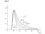
- FIG. 2 shows a graphical plot of various spectral components of a xenon light flash
- FIG. 3 shows a graphical plot of the UV transmission spectra of several selected gases
- FIG. 4 shows a two-beam gas analyzer in accordance with an embodiment of the invention
- FIG. 5 shows a first circuit of two photodetectors for the two-beam gas analyzer in accordance with the invention.
- FIG. 6 shows a second circuit of two photodetectors for the two-beam gas analyzer in accordance with embodiments of the invention.
- FIG. 1 shows a schematic illustration of a non-dispersive gas analyzer in a one-beam embodiment having a measuring cuvette 1 , through which a measured gas 2 to be analyzed flows.
- the measured gas 2 is a gas mixture made up of multiple components, of which one or more components of interest are to be quantitatively determined.
- a light source 3 in the form of a flash discharge lamp 4 for example, a xenon flash lamp, is activated by electrical pulses 5 and generates individual light flashes 6 , which are conducted through the measuring cuvette 1 onto a detector 7 .
- An analysis device 8 is connected downstream from the detector 7 , which analyzes the pulsed detector signal 10 , which is generated by the detector 7 as a reaction to the respective received light flash 9 , with respect to the pulse shape and delivers an analysis result 11 .
- FIG. 2 shows various spectral components of a xenon light flash 6 with their scaled output power P over the time t (taken from the above-mentioned technical information from Newport Corporation).
- the wavelength range of the light flash 6 extends from the infrared to the ultraviolet.
- the duration of the light flash 6 is shorter with respect to the short-wave components than in the case of the longer-wave components.
- Wavelength-dependent absorption of the light flash 6 occurs as it is transmitted through the measuring cuvette 1 by the components of the measured gas 2 , where many measured gas components of interest display very different absorption behavior.
- FIG. 3 shows exemplary absorption behavior (transmission T over the wavelength ⁇ ) of the relevant gases H 2 S, NO 2 , SO 2 , NO, and O 3 in environmental measuring technology in the ultraviolet range.
- the detector 7 ( FIG. 1 ) is selected so that it can detect the wavelengths of the respective observed wavelength range. For the above-mentioned gases, this is, e.g., the ultraviolet range.
- the detector 7 generates the detector signal 10 via the sum or the integral of the wavelengths; i.e., the detector 7 is non-selective.
- the detector 7 preferably detects the various wavelengths with more or less equal sensitivity. If the detector 7 is very broadband, interfering wavelength ranges outside the observed wavelength range can be masked out by an optical bandpass filter 12 .
- the emitted wavelength components vary over the duration of the light flash 6 .
- the wavelength-dependent absorption by the measured gas components also varies, so that the time pulse curve of the light flash 9 incident on the detector 7 is different from the light flash 6 generated by the flash discharge lamp 4 .
- the detected light flash 9 and therefore the detector signal 10 thus contain information about the absorption in the measuring cuvette 1 . If the wavelength-specific absorption bands of the measured gas components are different, i.e., they do not overlap or only partially overlap, the detected light flash 9 and therefore the detector signal 10 also contain information about the concentrations of the individual measured gas components in the measured gas 2 .
- the concentrations of selected measured gas components of interest are determined and output as the analysis result 11 .
- chemometric analysis methods come into consideration, in particular multivariate statistical methods. From the above statements, it results that the detector 7 must allow a time resolution of the received light flash 9 . A required time resolution in the microsecond range results from FIG. 2 . This can be achieved by optopneumatic detectors, photodiodes, or photocells.
- FIG. 4 shows a schematic illustration of a further exemplary embodiment of the gas analyzer according to the invention in a two-beam embodiment.
- a reference cuvette 13 is provided, which is filled with a reference or zero gas.
- the light 6 emitted by the light source 3 is portioned by a light distributor 14 , in the form of a reflector here, onto the measuring cuvette 1 and the reference cuvette 13 .
- a further detector 15 is arranged downstream from the reference cuvette 13 and the analysis device 8 analyzes the time difference pulse curve of the light flashes 9 , 16 incident on the detectors 7 , 15 .
- the two detectors consist of two gas-filled receiver chambers having an interposed differential pressure sensor or flow sensor 17 , which generates a detector signal 10 ′ corresponding to the differential pulse shape of the light flashes 9 , 16 incident on the detectors 7 , 15 .
- FIGS. 5 and 6 show two circuit examples known from EP 0 387 483 A1 having photodiodes 18 to implement the detectors 7 and 15 .
Abstract
Description
Claims (9)
Applications Claiming Priority (4)
| Application Number | Priority Date | Filing Date | Title |
|---|---|---|---|
| DE102010030549.9 | 2010-06-25 | ||
| DE102010030549.9A DE102010030549B4 (en) | 2010-06-25 | 2010-06-25 | Non-dispersive gas analyzer |
| DE102010030549 | 2010-06-25 | ||
| PCT/EP2011/060402 WO2011161137A1 (en) | 2010-06-25 | 2011-06-22 | Non-dispersive gas analyzer |
Publications (2)
| Publication Number | Publication Date |
|---|---|
| US20130208280A1 US20130208280A1 (en) | 2013-08-15 |
| US9030666B2 true US9030666B2 (en) | 2015-05-12 |
Family
ID=44630009
Family Applications (1)
| Application Number | Title | Priority Date | Filing Date |
|---|---|---|---|
| US13/805,225 Expired - Fee Related US9030666B2 (en) | 2010-06-25 | 2011-06-22 | Non-dispersive gas analyzer |
Country Status (4)
| Country | Link |
|---|---|
| US (1) | US9030666B2 (en) |
| EP (1) | EP2585810A1 (en) |
| DE (1) | DE102010030549B4 (en) |
| WO (1) | WO2011161137A1 (en) |
Families Citing this family (2)
| Publication number | Priority date | Publication date | Assignee | Title |
|---|---|---|---|---|
| DE102015106373B4 (en) * | 2015-04-24 | 2023-03-02 | Infineon Technologies Ag | PHOTOACOUSTIC GAS SENSOR MODULE WITH LIGHT EMITTER UNIT AND DETECTOR UNIT |
| DE202021104857U1 (en) | 2021-09-09 | 2022-12-20 | Sick Ag | analysis device |
Citations (39)
| Publication number | Priority date | Publication date | Assignee | Title |
|---|---|---|---|---|
| US3810696A (en) | 1973-02-20 | 1974-05-14 | Waters Associates Inc | Improved analytical apparatus for measuring light absorbance of fluids |
| US4271124A (en) * | 1978-02-24 | 1981-06-02 | Siemens Aktiengesellschaft | Non-dispersive infrared gas analyzer for testing gases containing water-vapor |
| US4320297A (en) * | 1979-11-29 | 1982-03-16 | Beckman Instruments, Inc. | Split detector |
| US4355233A (en) * | 1979-02-22 | 1982-10-19 | Beckman Instruments, Inc. | Method and apparatus for negating measurement effects of interferent gases in non-dispersive infrared analyzers |
| US4420687A (en) * | 1982-10-28 | 1983-12-13 | Teledyne Ind | Non-dispersive infrared gas analyzer |
| US4687329A (en) | 1985-03-21 | 1987-08-18 | Abbott Laboratories | Spectrophotometer |
| US4692621A (en) * | 1985-10-11 | 1987-09-08 | Andros Anlayzers Incorporated | Digital anesthetic agent analyzer |
| EP0283047A2 (en) | 1987-03-19 | 1988-09-21 | Max-Planck-Gesellschaft zur Förderung der Wissenschaften e.V. | Method and device for contactless aquisition of data for the spatial resolution of density and temperature in a volume sample |
| US4899053A (en) | 1987-10-21 | 1990-02-06 | Criticare Systems, Inc. | Solid state non-dispersive IR analyzer using electrical current-modulated microsources |
| EP0387483A1 (en) | 1989-03-16 | 1990-09-19 | Landis & Gyr Business Support AG | Ultraviolet photodiode |
| DE3902015C2 (en) | 1989-01-25 | 1991-07-18 | Diehl Gmbh & Co, 8500 Nuernberg, De | |
| US5080767A (en) * | 1989-04-07 | 1992-01-14 | Mitsui Toatsu Chemicals, Inc. | Process for preparing aromatic compounds having chlorinated side chains and method for stabilizing monochloro-side chain aromatic compounds |
| EP0591758A1 (en) | 1992-09-26 | 1994-04-13 | Forschungszentrum Karlsruhe GmbH | Multi-components analysing device |
| DE3887528T2 (en) | 1987-11-03 | 1994-08-18 | Radiometer As | METHOD FOR DETERMINING THE OXYGEN CONTENT. |
| US5429805A (en) * | 1993-01-08 | 1995-07-04 | Fuji Electric Co., Ltd. | Non-dispersive infrared gas analyzer including gas-filled radiation source |
| DE4403763A1 (en) | 1994-02-07 | 1995-08-10 | Siemens Ag | Infra red gas absorption for rapid, sensitive and accurate, quantified analysis |
| DE4440968A1 (en) | 1994-11-17 | 1996-05-30 | Heinrich Spiecker | Spectroscopic system |
| EP0758079A2 (en) | 1995-08-07 | 1997-02-12 | MICROPARTS GESELLSCHAFT FÜR MIKROSTRUKTURTECHNIK mbH | Microstructured infrared absorption photometer |
| DE19608907C1 (en) | 1996-03-07 | 1997-04-03 | Siemens Ag | Non-dispersive gas analyser |
| US5807750A (en) * | 1995-05-02 | 1998-09-15 | Air Instruments And Measurements, Inc. | Optical substance analyzer and data processor |
| US5886348A (en) * | 1997-02-14 | 1999-03-23 | American Intell-Sensors Corporation | Non-dispersive infrared gas analyzer with interfering gas correction |
| WO1999014576A2 (en) | 1997-09-17 | 1999-03-25 | Oridion Medical Ltd. | Isotopic gas analyzer |
| US6074607A (en) | 1996-04-01 | 2000-06-13 | Bayer Corporation | Oxygen sensing membranes |
| US6166383A (en) * | 1997-07-28 | 2000-12-26 | Siemens Ag | Non-dispersive infrared gas analyzer |
| GB2358245A (en) | 1999-10-21 | 2001-07-18 | Pittway Corp | Photo-acoustic gas sensor |
| US20010032514A1 (en) * | 2000-03-13 | 2001-10-25 | Suzuki Motor Corporation | Vibration measuring apparatus and method |
| US20020101592A1 (en) | 2001-02-01 | 2002-08-01 | Zare Richard N. | Pulse-by-pulse cavity ring-down spectroscopy |
| WO2004048907A2 (en) | 2002-11-25 | 2004-06-10 | Ruth Albert A | Resonator-amplified absorption spectrometer comprising an incoherent radiation source |
| US6794670B1 (en) | 1999-09-22 | 2004-09-21 | Astrazeneca Ab | Method and apparatus for spectrometric analysis of turbid, pharmaceutical samples |
| US20050082483A1 (en) * | 2003-10-10 | 2005-04-21 | Takuji Oida | Absorbance monitor |
| US20050157303A1 (en) | 2002-04-09 | 2005-07-21 | Nigel Langford | Semiconductor diode laser spectrometer arrangement and method |
| US20060181710A1 (en) | 2005-02-16 | 2006-08-17 | Alexander Kachanov | Method for the precise measurement of the wavelength of light |
| DE102005036410A1 (en) | 2005-07-29 | 2007-02-01 | Biocam Gmbh | Method for determining the oxygen partial pressure distribution in at least one tissue surface section, in particular skin tissue surface section |
| US7180595B2 (en) * | 2003-09-12 | 2007-02-20 | Ir Microsystems Ag | Gas detection method and gas detector device |
| US20070216903A1 (en) | 2006-03-17 | 2007-09-20 | Cole Barrett E | Cavity ring-down spectrometer for semiconductor processing |
| WO2007107366A1 (en) | 2006-03-17 | 2007-09-27 | Freie Universität Berlin | Apparatus for spectroscopically analysing a gas |
| WO2009101197A1 (en) | 2008-02-15 | 2009-08-20 | Siemens Aktiengesellschaft | Non-dispersive infrared gas analyzer |
| DE102008044317A1 (en) | 2008-12-03 | 2010-06-17 | Universität Potsdam | Apparatus and method for determining the concentration of oxygen |
| US20120205547A1 (en) * | 2011-02-10 | 2012-08-16 | Zaps Technologies, Inc. | Method and Apparatus for the Optical Determination of Total Organic Carbon in Aqueous Streams |
-
2010
- 2010-06-25 DE DE102010030549.9A patent/DE102010030549B4/en not_active Expired - Fee Related
-
2011
- 2011-06-22 US US13/805,225 patent/US9030666B2/en not_active Expired - Fee Related
- 2011-06-22 EP EP11741531.5A patent/EP2585810A1/en not_active Withdrawn
- 2011-06-22 WO PCT/EP2011/060402 patent/WO2011161137A1/en active Application Filing
Patent Citations (51)
| Publication number | Priority date | Publication date | Assignee | Title |
|---|---|---|---|---|
| US3810696A (en) | 1973-02-20 | 1974-05-14 | Waters Associates Inc | Improved analytical apparatus for measuring light absorbance of fluids |
| DE2408197A1 (en) | 1973-02-20 | 1974-08-22 | Waters Associates Inc | SPECTROMETER |
| US4271124A (en) * | 1978-02-24 | 1981-06-02 | Siemens Aktiengesellschaft | Non-dispersive infrared gas analyzer for testing gases containing water-vapor |
| US4355233A (en) * | 1979-02-22 | 1982-10-19 | Beckman Instruments, Inc. | Method and apparatus for negating measurement effects of interferent gases in non-dispersive infrared analyzers |
| US4320297A (en) * | 1979-11-29 | 1982-03-16 | Beckman Instruments, Inc. | Split detector |
| US4420687A (en) * | 1982-10-28 | 1983-12-13 | Teledyne Ind | Non-dispersive infrared gas analyzer |
| EP0195339B1 (en) | 1985-03-21 | 1992-07-29 | Abbott Laboratories | Spectrophotometer |
| US4687329A (en) | 1985-03-21 | 1987-08-18 | Abbott Laboratories | Spectrophotometer |
| US4692621A (en) * | 1985-10-11 | 1987-09-08 | Andros Anlayzers Incorporated | Digital anesthetic agent analyzer |
| EP0283047A2 (en) | 1987-03-19 | 1988-09-21 | Max-Planck-Gesellschaft zur Förderung der Wissenschaften e.V. | Method and device for contactless aquisition of data for the spatial resolution of density and temperature in a volume sample |
| US4986654A (en) | 1987-03-19 | 1991-01-22 | Max-Planck-Gesellschaft . . . E.V. | Method and apparatus for contactless acquisition of data for the locally resolved determination of the density and temperature in a measurement volume |
| US4899053A (en) | 1987-10-21 | 1990-02-06 | Criticare Systems, Inc. | Solid state non-dispersive IR analyzer using electrical current-modulated microsources |
| DE3887528T2 (en) | 1987-11-03 | 1994-08-18 | Radiometer As | METHOD FOR DETERMINING THE OXYGEN CONTENT. |
| DE3902015C2 (en) | 1989-01-25 | 1991-07-18 | Diehl Gmbh & Co, 8500 Nuernberg, De | |
| EP0387483A1 (en) | 1989-03-16 | 1990-09-19 | Landis & Gyr Business Support AG | Ultraviolet photodiode |
| US5130776A (en) | 1989-03-16 | 1992-07-14 | Landis & Gyr Betriebs Ag | Ultraviolet-light photodiode |
| US5080767A (en) * | 1989-04-07 | 1992-01-14 | Mitsui Toatsu Chemicals, Inc. | Process for preparing aromatic compounds having chlorinated side chains and method for stabilizing monochloro-side chain aromatic compounds |
| EP0591758A1 (en) | 1992-09-26 | 1994-04-13 | Forschungszentrum Karlsruhe GmbH | Multi-components analysing device |
| US5429805A (en) * | 1993-01-08 | 1995-07-04 | Fuji Electric Co., Ltd. | Non-dispersive infrared gas analyzer including gas-filled radiation source |
| DE4403763A1 (en) | 1994-02-07 | 1995-08-10 | Siemens Ag | Infra red gas absorption for rapid, sensitive and accurate, quantified analysis |
| DE4440968A1 (en) | 1994-11-17 | 1996-05-30 | Heinrich Spiecker | Spectroscopic system |
| US5807750A (en) * | 1995-05-02 | 1998-09-15 | Air Instruments And Measurements, Inc. | Optical substance analyzer and data processor |
| US5734165A (en) | 1995-08-07 | 1998-03-31 | Microparts Gesellschaft Fuer Mikrostrukturtechnik Mbh | Microstructured infrared absorption photometer |
| EP0758079A2 (en) | 1995-08-07 | 1997-02-12 | MICROPARTS GESELLSCHAFT FÜR MIKROSTRUKTURTECHNIK mbH | Microstructured infrared absorption photometer |
| DE19608907C1 (en) | 1996-03-07 | 1997-04-03 | Siemens Ag | Non-dispersive gas analyser |
| DE69729632T2 (en) | 1996-04-01 | 2005-07-07 | Bayer Corp., East Walpole | OXYGEN SENSOR MEMBRANES AND METHOD FOR THE PRODUCTION THEREOF |
| US6074607A (en) | 1996-04-01 | 2000-06-13 | Bayer Corporation | Oxygen sensing membranes |
| US5886348A (en) * | 1997-02-14 | 1999-03-23 | American Intell-Sensors Corporation | Non-dispersive infrared gas analyzer with interfering gas correction |
| US6166383A (en) * | 1997-07-28 | 2000-12-26 | Siemens Ag | Non-dispersive infrared gas analyzer |
| WO1999014576A2 (en) | 1997-09-17 | 1999-03-25 | Oridion Medical Ltd. | Isotopic gas analyzer |
| US7063667B1 (en) | 1997-09-17 | 2006-06-20 | Oridion Breathid Ltd. | Isotopic gas analyzer |
| DE69828799T2 (en) | 1997-09-17 | 2006-01-05 | Oridion Breathid Ltd. | ISOTOPE GAS ANALYZER |
| US6794670B1 (en) | 1999-09-22 | 2004-09-21 | Astrazeneca Ab | Method and apparatus for spectrometric analysis of turbid, pharmaceutical samples |
| GB2358245A (en) | 1999-10-21 | 2001-07-18 | Pittway Corp | Photo-acoustic gas sensor |
| US20010032514A1 (en) * | 2000-03-13 | 2001-10-25 | Suzuki Motor Corporation | Vibration measuring apparatus and method |
| US20020101592A1 (en) | 2001-02-01 | 2002-08-01 | Zare Richard N. | Pulse-by-pulse cavity ring-down spectroscopy |
| US20050157303A1 (en) | 2002-04-09 | 2005-07-21 | Nigel Langford | Semiconductor diode laser spectrometer arrangement and method |
| WO2004048907A2 (en) | 2002-11-25 | 2004-06-10 | Ruth Albert A | Resonator-amplified absorption spectrometer comprising an incoherent radiation source |
| US7755767B2 (en) | 2002-11-25 | 2010-07-13 | Ruth Albert A | Resonator-amplified absorption spectrometer |
| US7180595B2 (en) * | 2003-09-12 | 2007-02-20 | Ir Microsystems Ag | Gas detection method and gas detector device |
| US20050082483A1 (en) * | 2003-10-10 | 2005-04-21 | Takuji Oida | Absorbance monitor |
| US20060181710A1 (en) | 2005-02-16 | 2006-08-17 | Alexander Kachanov | Method for the precise measurement of the wavelength of light |
| US20090146080A1 (en) | 2005-07-29 | 2009-06-11 | Gregor Liebsch | Method and measuring system for determining the oxygen partial pressure distribution in at least one tissue surface section, in particular skin tissue surface section |
| DE102005036410A1 (en) | 2005-07-29 | 2007-02-01 | Biocam Gmbh | Method for determining the oxygen partial pressure distribution in at least one tissue surface section, in particular skin tissue surface section |
| WO2007107366A1 (en) | 2006-03-17 | 2007-09-27 | Freie Universität Berlin | Apparatus for spectroscopically analysing a gas |
| US20090124918A1 (en) | 2006-03-17 | 2009-05-14 | Freie Universitaetsmedizin Berlin, | Apparatus For Spectroscopically Analyzing A Gas |
| US20070216903A1 (en) | 2006-03-17 | 2007-09-20 | Cole Barrett E | Cavity ring-down spectrometer for semiconductor processing |
| WO2009101197A1 (en) | 2008-02-15 | 2009-08-20 | Siemens Aktiengesellschaft | Non-dispersive infrared gas analyzer |
| US8044353B2 (en) | 2008-02-15 | 2011-10-25 | Siemens Aktiengesellschaft | Non-dispersive infrared gas analyzer |
| DE102008044317A1 (en) | 2008-12-03 | 2010-06-17 | Universität Potsdam | Apparatus and method for determining the concentration of oxygen |
| US20120205547A1 (en) * | 2011-02-10 | 2012-08-16 | Zaps Technologies, Inc. | Method and Apparatus for the Optical Determination of Total Organic Carbon in Aqueous Streams |
Non-Patent Citations (5)
| Title |
|---|
| File: Rare gas flashtube spectral outputs.JPG; http://en.wikipedia.org/wiki/File:Rare-gas-flashtube-spectral-outputs.jpg Jun. 15, 2010 (3 pages). |
| File: Rare gas flashtube spectral outputs.JPG; http://en.wikipedia.org/wiki/File:Rare—gas—flashtube—spectral—outputs.jpg Jun. 15, 2010 (3 pages). |
| J. Staab: "Industrielle Gasanalyse", R. Oldenbourg Verlag München Wien, 1994, Seiten 83, 133. |
| Oriel Xenon Flashlamp System, Light Sources http://support.newport.com/file-store/PDFs/tempPDFs/e5457-Oriel-Xenon-Flashlamp-Systems.pdf Jun. 15, 2010 (3 pages). |
| Oriel Xenon Flashlamp System, Light Sources http://support.newport.com/file—store/PDFs/tempPDFs/e5457—Oriel-Xenon-Flashlamp-Systems.pdf Jun. 15, 2010 (3 pages). |
Also Published As
| Publication number | Publication date |
|---|---|
| DE102010030549A1 (en) | 2011-12-29 |
| EP2585810A1 (en) | 2013-05-01 |
| DE102010030549B4 (en) | 2016-04-28 |
| US20130208280A1 (en) | 2013-08-15 |
| WO2011161137A1 (en) | 2011-12-29 |
Similar Documents
| Publication | Publication Date | Title |
|---|---|---|
| EP2693198B1 (en) | Gas analyser and method for measuring the concentration of formaldehyde | |
| Rohwedder et al. | iHWG-μNIR: a miniaturised near-infrared gas sensor based on substrate-integrated hollow waveguides coupled to a micro-NIR-spectrophotometer | |
| EP3049806B1 (en) | Method and system for gas concentration measurement of gas dissolved in liquids | |
| JP6413759B2 (en) | Optical analyzer | |
| KR20110127122A (en) | Sample analyzing apparatus | |
| KR20150115036A (en) | NO/NO2 multi-gases analyzer using non-dispersive ultraviolet method and NO/NO2 multi-gases analyzing method | |
| JP6059484B2 (en) | High-resolution measuring device for substance concentration in fluid media | |
| US9030666B2 (en) | Non-dispersive gas analyzer | |
| CN104880434A (en) | Detection device and method for weak absorbing gas in complex environment | |
| US9921196B2 (en) | Gas chromatograph having an absorption spectrometer and method for analyzing a gas mixture via gas chromatography | |
| KR101381618B1 (en) | Multi-gas analysis device using non dispersion ultraviolet absorption spectrophotometer | |
| Lou et al. | Sulfur dioxide measurements using an ultraviolet light-emitting diode in combination with gas correlation techniques | |
| SE0800374L (en) | Distance detection of hazardous substances such as explosives and constituents of explosives | |
| JP5296723B2 (en) | Spectrophotometer and performance measurement method thereof | |
| KR101317059B1 (en) | Multi-gas analysis device for ultra-violet measurements | |
| US11248958B2 (en) | ATR spectrometer and method for analysing the chemical composition of a sample | |
| RU89233U1 (en) | GAS ANALYZER | |
| CN111912804A (en) | Ultraviolet spectrum detection method and device for monitoring trace sulfur dioxide in blast furnace flue gas | |
| EP2679983A1 (en) | A method and apparatus for quantification of gaseous elemental mercury in a gaseous sample | |
| JP7184924B2 (en) | Measurement of hydrocarbon contamination in water | |
| US10101271B2 (en) | Measurement of hydrocarbon contamination in water | |
| JP2023539429A (en) | Absorption spectrometer and how to use it | |
| RU143639U1 (en) | DEVICE FOR REMOTE IDENTIFICATION OF VAPORS AND AEROSOLS OF SUBSTANCES IN OPEN AND CLOSED GAS MEDIA | |
| RU81334U1 (en) | OPTICAL GAS ANALYZER |
Legal Events
| Date | Code | Title | Description |
|---|---|---|---|
| AS | Assignment |
Owner name: SIEMENS AKTIENGESELLSCHAFT, GERMANY Free format text: ASSIGNMENT OF ASSIGNORS INTEREST;ASSIGNORS:BITTER, RALF;HEFFELS, CAMIEL;HOERNER, THOMAS;SIGNING DATES FROM 20130207 TO 20130208;REEL/FRAME:030176/0280 |
|
| STCF | Information on status: patent grant |
Free format text: PATENTED CASE |
|
| FEPP | Fee payment procedure |
Free format text: MAINTENANCE FEE REMINDER MAILED (ORIGINAL EVENT CODE: REM.); ENTITY STATUS OF PATENT OWNER: LARGE ENTITY |
|
| LAPS | Lapse for failure to pay maintenance fees |
Free format text: PATENT EXPIRED FOR FAILURE TO PAY MAINTENANCE FEES (ORIGINAL EVENT CODE: EXP.); ENTITY STATUS OF PATENT OWNER: LARGE ENTITY |
|
| STCH | Information on status: patent discontinuation |
Free format text: PATENT EXPIRED DUE TO NONPAYMENT OF MAINTENANCE FEES UNDER 37 CFR 1.362 |
|
| FP | Lapsed due to failure to pay maintenance fee |
Effective date: 20190512 |