US9055920B2 - Ultrasound system and signal processing unit configured for time gain and lateral gain compensation - Google Patents
Ultrasound system and signal processing unit configured for time gain and lateral gain compensation Download PDFInfo
- Publication number
- US9055920B2 US9055920B2 US13/475,686 US201213475686A US9055920B2 US 9055920 B2 US9055920 B2 US 9055920B2 US 201213475686 A US201213475686 A US 201213475686A US 9055920 B2 US9055920 B2 US 9055920B2
- Authority
- US
- United States
- Prior art keywords
- compensation
- line
- tgc
- lgc
- touch input
- Prior art date
- Legal status (The legal status is an assumption and is not a legal conclusion. Google has not performed a legal analysis and makes no representation as to the accuracy of the status listed.)
- Active
Links
Images


Classifications
-
- A—HUMAN NECESSITIES
- A61—MEDICAL OR VETERINARY SCIENCE; HYGIENE
- A61B—DIAGNOSIS; SURGERY; IDENTIFICATION
- A61B8/00—Diagnosis using ultrasonic, sonic or infrasonic waves
- A61B8/52—Devices using data or image processing specially adapted for diagnosis using ultrasonic, sonic or infrasonic waves
- A61B8/5207—Devices using data or image processing specially adapted for diagnosis using ultrasonic, sonic or infrasonic waves involving processing of raw data to produce diagnostic data, e.g. for generating an image
-
- A—HUMAN NECESSITIES
- A61—MEDICAL OR VETERINARY SCIENCE; HYGIENE
- A61B—DIAGNOSIS; SURGERY; IDENTIFICATION
- A61B8/00—Diagnosis using ultrasonic, sonic or infrasonic waves
-
- A—HUMAN NECESSITIES
- A61—MEDICAL OR VETERINARY SCIENCE; HYGIENE
- A61B—DIAGNOSIS; SURGERY; IDENTIFICATION
- A61B8/00—Diagnosis using ultrasonic, sonic or infrasonic waves
- A61B8/13—Tomography
- A61B8/14—Echo-tomography
-
- A—HUMAN NECESSITIES
- A61—MEDICAL OR VETERINARY SCIENCE; HYGIENE
- A61B—DIAGNOSIS; SURGERY; IDENTIFICATION
- A61B8/00—Diagnosis using ultrasonic, sonic or infrasonic waves
- A61B8/42—Details of probe positioning or probe attachment to the patient
- A61B8/4245—Details of probe positioning or probe attachment to the patient involving determining the position of the probe, e.g. with respect to an external reference frame or to the patient
- A61B8/4254—Details of probe positioning or probe attachment to the patient involving determining the position of the probe, e.g. with respect to an external reference frame or to the patient using sensors mounted on the probe
-
- A—HUMAN NECESSITIES
- A61—MEDICAL OR VETERINARY SCIENCE; HYGIENE
- A61B—DIAGNOSIS; SURGERY; IDENTIFICATION
- A61B8/00—Diagnosis using ultrasonic, sonic or infrasonic waves
- A61B8/44—Constructional features of the ultrasonic, sonic or infrasonic diagnostic device
- A61B8/4444—Constructional features of the ultrasonic, sonic or infrasonic diagnostic device related to the probe
-
- A—HUMAN NECESSITIES
- A61—MEDICAL OR VETERINARY SCIENCE; HYGIENE
- A61B—DIAGNOSIS; SURGERY; IDENTIFICATION
- A61B8/00—Diagnosis using ultrasonic, sonic or infrasonic waves
- A61B8/46—Ultrasonic, sonic or infrasonic diagnostic devices with special arrangements for interfacing with the operator or the patient
- A61B8/461—Displaying means of special interest
- A61B8/462—Displaying means of special interest characterised by constructional features of the display
-
- A—HUMAN NECESSITIES
- A61—MEDICAL OR VETERINARY SCIENCE; HYGIENE
- A61B—DIAGNOSIS; SURGERY; IDENTIFICATION
- A61B8/00—Diagnosis using ultrasonic, sonic or infrasonic waves
- A61B8/46—Ultrasonic, sonic or infrasonic diagnostic devices with special arrangements for interfacing with the operator or the patient
- A61B8/461—Displaying means of special interest
- A61B8/463—Displaying means of special interest characterised by displaying multiple images or images and diagnostic data on one display
-
- A—HUMAN NECESSITIES
- A61—MEDICAL OR VETERINARY SCIENCE; HYGIENE
- A61B—DIAGNOSIS; SURGERY; IDENTIFICATION
- A61B8/00—Diagnosis using ultrasonic, sonic or infrasonic waves
- A61B8/46—Ultrasonic, sonic or infrasonic diagnostic devices with special arrangements for interfacing with the operator or the patient
- A61B8/461—Displaying means of special interest
- A61B8/465—Displaying means of special interest adapted to display user selection data, e.g. icons or menus
-
- A—HUMAN NECESSITIES
- A61—MEDICAL OR VETERINARY SCIENCE; HYGIENE
- A61B—DIAGNOSIS; SURGERY; IDENTIFICATION
- A61B8/00—Diagnosis using ultrasonic, sonic or infrasonic waves
- A61B8/46—Ultrasonic, sonic or infrasonic diagnostic devices with special arrangements for interfacing with the operator or the patient
- A61B8/467—Ultrasonic, sonic or infrasonic diagnostic devices with special arrangements for interfacing with the operator or the patient characterised by special input means
-
- A—HUMAN NECESSITIES
- A61—MEDICAL OR VETERINARY SCIENCE; HYGIENE
- A61B—DIAGNOSIS; SURGERY; IDENTIFICATION
- A61B8/00—Diagnosis using ultrasonic, sonic or infrasonic waves
- A61B8/52—Devices using data or image processing specially adapted for diagnosis using ultrasonic, sonic or infrasonic waves
- A61B8/5269—Devices using data or image processing specially adapted for diagnosis using ultrasonic, sonic or infrasonic waves involving detection or reduction of artifacts
-
- A—HUMAN NECESSITIES
- A61—MEDICAL OR VETERINARY SCIENCE; HYGIENE
- A61B—DIAGNOSIS; SURGERY; IDENTIFICATION
- A61B8/00—Diagnosis using ultrasonic, sonic or infrasonic waves
- A61B8/54—Control of the diagnostic device
-
- G—PHYSICS
- G01—MEASURING; TESTING
- G01N—INVESTIGATING OR ANALYSING MATERIALS BY DETERMINING THEIR CHEMICAL OR PHYSICAL PROPERTIES
- G01N29/00—Investigating or analysing materials by the use of ultrasonic, sonic or infrasonic waves; Visualisation of the interior of objects by transmitting ultrasonic or sonic waves through the object
- G01N29/22—Details, e.g. general constructional or apparatus details
- G01N29/24—Probes
-
- G—PHYSICS
- G01—MEASURING; TESTING
- G01S—RADIO DIRECTION-FINDING; RADIO NAVIGATION; DETERMINING DISTANCE OR VELOCITY BY USE OF RADIO WAVES; LOCATING OR PRESENCE-DETECTING BY USE OF THE REFLECTION OR RERADIATION OF RADIO WAVES; ANALOGOUS ARRANGEMENTS USING OTHER WAVES
- G01S5/00—Position-fixing by co-ordinating two or more direction or position line determinations; Position-fixing by co-ordinating two or more distance determinations
- G01S5/18—Position-fixing by co-ordinating two or more direction or position line determinations; Position-fixing by co-ordinating two or more distance determinations using ultrasonic, sonic, or infrasonic waves
-
- G—PHYSICS
- G01—MEASURING; TESTING
- G01S—RADIO DIRECTION-FINDING; RADIO NAVIGATION; DETERMINING DISTANCE OR VELOCITY BY USE OF RADIO WAVES; LOCATING OR PRESENCE-DETECTING BY USE OF THE REFLECTION OR RERADIATION OF RADIO WAVES; ANALOGOUS ARRANGEMENTS USING OTHER WAVES
- G01S7/00—Details of systems according to groups G01S13/00, G01S15/00, G01S17/00
- G01S7/52—Details of systems according to groups G01S13/00, G01S15/00, G01S17/00 of systems according to group G01S15/00
- G01S7/52017—Details of systems according to groups G01S13/00, G01S15/00, G01S17/00 of systems according to group G01S15/00 particularly adapted to short-range imaging
- G01S7/52023—Details of receivers
- G01S7/52033—Gain control of receivers
-
- G—PHYSICS
- G01—MEASURING; TESTING
- G01S—RADIO DIRECTION-FINDING; RADIO NAVIGATION; DETERMINING DISTANCE OR VELOCITY BY USE OF RADIO WAVES; LOCATING OR PRESENCE-DETECTING BY USE OF THE REFLECTION OR RERADIATION OF RADIO WAVES; ANALOGOUS ARRANGEMENTS USING OTHER WAVES
- G01S7/00—Details of systems according to groups G01S13/00, G01S15/00, G01S17/00
- G01S7/52—Details of systems according to groups G01S13/00, G01S15/00, G01S17/00 of systems according to group G01S15/00
- G01S7/52017—Details of systems according to groups G01S13/00, G01S15/00, G01S17/00 of systems according to group G01S15/00 particularly adapted to short-range imaging
- G01S7/52079—Constructional features
- G01S7/52084—Constructional features related to particular user interfaces
-
- G—PHYSICS
- G06—COMPUTING; CALCULATING OR COUNTING
- G06F—ELECTRIC DIGITAL DATA PROCESSING
- G06F3/00—Input arrangements for transferring data to be processed into a form capable of being handled by the computer; Output arrangements for transferring data from processing unit to output unit, e.g. interface arrangements
- G06F3/01—Input arrangements or combined input and output arrangements for interaction between user and computer
- G06F3/048—Interaction techniques based on graphical user interfaces [GUI]
- G06F3/0484—Interaction techniques based on graphical user interfaces [GUI] for the control of specific functions or operations, e.g. selecting or manipulating an object, an image or a displayed text element, setting a parameter value or selecting a range
- G06F3/04845—Interaction techniques based on graphical user interfaces [GUI] for the control of specific functions or operations, e.g. selecting or manipulating an object, an image or a displayed text element, setting a parameter value or selecting a range for image manipulation, e.g. dragging, rotation, expansion or change of colour
-
- G—PHYSICS
- G06—COMPUTING; CALCULATING OR COUNTING
- G06F—ELECTRIC DIGITAL DATA PROCESSING
- G06F3/00—Input arrangements for transferring data to be processed into a form capable of being handled by the computer; Output arrangements for transferring data from processing unit to output unit, e.g. interface arrangements
- G06F3/01—Input arrangements or combined input and output arrangements for interaction between user and computer
- G06F3/048—Interaction techniques based on graphical user interfaces [GUI]
- G06F3/0484—Interaction techniques based on graphical user interfaces [GUI] for the control of specific functions or operations, e.g. selecting or manipulating an object, an image or a displayed text element, setting a parameter value or selecting a range
- G06F3/04847—Interaction techniques to control parameter settings, e.g. interaction with sliders or dials
-
- G—PHYSICS
- G06—COMPUTING; CALCULATING OR COUNTING
- G06T—IMAGE DATA PROCESSING OR GENERATION, IN GENERAL
- G06T7/00—Image analysis
- G06T7/0002—Inspection of images, e.g. flaw detection
- G06T7/0012—Biomedical image inspection
-
- A—HUMAN NECESSITIES
- A61—MEDICAL OR VETERINARY SCIENCE; HYGIENE
- A61B—DIAGNOSIS; SURGERY; IDENTIFICATION
- A61B6/00—Apparatus for radiation diagnosis, e.g. combined with radiation therapy equipment
- A61B6/46—Apparatus for radiation diagnosis, e.g. combined with radiation therapy equipment with special arrangements for interfacing with the operator or the patient
- A61B6/467—Apparatus for radiation diagnosis, e.g. combined with radiation therapy equipment with special arrangements for interfacing with the operator or the patient characterised by special input means
Definitions
- the present invention generally relates to an ultrasound system, and more particularly to an ultrasound system adapted to precisely and easily perform TGC (Time Gain Compensation) and LGC (Lateral Gain Compensation).
- An ultrasound system has become an important and popular diagnostic tool since it has a wide range of applications. Specifically, due to its non-invasive and non-destructive nature, the ultrasound system has been extensively used in the medical profession. Modern high-performance ultrasound systems and techniques are commonly used to produce two or three-dimensional diagnostic images of internal features of an object.
- the ultrasound system In order to transmit and receive ultrasound signals, the ultrasound system is generally provided with a probe including a wideband transducer.
- the transducer When the transducer is electrically stimulated, it produces ultrasound signals and transmits them into a human body.
- the ultrasound signals transmitted into the human body are reflected from borders between human tissues and then returned to the transducer.
- the returned ultrasound echo signals are converted into electric signals.
- ultrasound image data for imaging the tissues is produced by amplifying and signal-processing the echo signals.
- the ultrasound system is provided with a control panel including a plurality of input units in order to perform a control function of acquiring the ultrasound image, a menu control function, a measurement and annotation function, etc.
- the control panel is comprised of a touch panel, an image control unit, a measurement control unit, etc.
- the touch panel displays menus for optimizing an ultrasound image displayed on a display unit. The menus on the touch panel can be touched and selected by a user.
- the image control unit controls the ultrasound image, whereas the measurement control unit measures a distance to the object, a circumference of the object, etc.
- the image control unit includes a plurality of TGC control keys 11 and a plurality of LGC control keys 12 .
- the TGC control keys 11 are used to control a gain of each echo signal based on depth of the position from which the echo signal is reflected. Further, since the echo signal is attenuated at the outer right and left sides, the LGC control keys 12 are used to control a gain of the attenuated echo signal.
- the TGC control keys 11 and the LGC control keys 12 are arranged on different areas of the control panel.
- the problem associated with such an arrangement is that the size of the control panel must be inevitably increased. Further, a user of the system suffers a great inconvenience when operating the TGC control keys 11 and the LGC control keys 12 .
- Another problem of the conventional system is that since the TGC control keys 11 and the LGC control keys 12 are comprised of slide-type variable resistors, it is very difficult for an unskilled user to finely control TGC and LGC with the TGC control keys 11 and the LGC control keys 12 .
- the present invention is directed to providing an ultrasound system adapted to display a setup screen used to input TGC and LGC curves on a touch panel and perform TGC and LGC based on the inputted TGC and LGC curves.
- the present invention provides an ultrasound system, which comprises: a signal acquiring unit adapted to transmit an ultrasound signal to an object and acquire an echo signal reflected from the object; a signal processing unit adapted to perform TGC (Time Gain Compensation) and LGC (Lateral Gain Compensation) upon the echo signal at a coarse compensation mode based on predetermined TGC and LGC values; an image producing unit adapted to produce an ultrasound image of the object based on the TGC and LGC compensated echo signal; an input unit adapted to allow a user to provide TGC and LGC curves; and a TGC/LGC setup processor adapted to set TGC and LGC values based on the TGC and LGC curves provided by the user.
- the signal processing unit is further adapted to perform the TGC and LGC upon the echo signal at a fine compensation mode based on the TGC and LGC values set by the TGC/LGC setup processor.
- the present invention provides an ultrasound system, which comprises: a processor adapted to configure a setup screen for display; and a touch panel adapted to display the setup screen so as to allow a user to input TGC and LGC curves.
- the processor is further adapted to calculate the TGC and LGC values based on the inputted TGC and the LGC curves.
- FIG. 1 is a schematic diagram illustrating conventional TGC and LGC control keys
- FIG. 2 is a block diagram showing a structure of an ultrasound system according to one embodiment of the present invention.
- FIGS. 3 to 7 illustrate a setup screen according to one embodiment of the present.
- FIG. 8 illustrates an exemplary distinction between TGC and LGC curves according to one embodiment of the present invention.
- an ultrasound system 100 comprises: a probe 110 ; a beam former 120 ; a signal processing unit 130 ; a processor 140 ; a display unit 150 ; and a TGC/LGC setup unit 160 .
- the probe 110 includes a plurality of transducers 112 . Each of the transducers 112 may be configured to transmit an ultrasound signal to an object and receive the ultrasound signal reflected from the object.
- the beam former 120 may be configured to focus the transmitted ultrasound signals from the transducers 112 on the object and collect the reflected ultrasound signals from the object to the transducers 112 together with corresponding time delay.
- the signal processing unit 130 may be configured to amplify the signals collected by the beam former 120 and control gains of the amplified echo signals. Specifically, the signal processing unit 130 may be configured to perform TGC (Time Gain Compensation) and LGC (Lateral Gain Compensation) upon the echo signals based on predetermined TGC and LGC values at a coarse compensation mode (e.g., in an initial operation stage). The signal processing unit 130 may be further configured to perform TGC and LGC upon the echo signals based on TGC and LGC values calculated in a TGC/LGC setup unit 160 using a curve inputted by a user at a fine compensation mode (e.g., during operations).
- TGC Time Gain Compensation
- LGC Layer Gain Compensation
- the processor 140 may be configured to receive the echo signals from the signal processing unit 130 and produce an ultrasound image signal based on the echo signals.
- the display unit 150 may be adapted to receive the ultrasound image signal from the processor and display an ultrasound image based on the signal.
- the TGC/LGC setup unit 160 may include a touch panel 161 and a TGC/LGC setup processor 162 .
- the touch panel 161 may be configured to display a setup screen and detect TGC/LGC curves inputted by the user on the touch panel 161 to produce a detecting signal.
- the touch panel 161 detects the user's input according to either the pressure sensing method or the electromagnetic induction method.
- the touch panel 161 may be a touch panel included in a control panel (not shown) of the ultrasound system 100 . Alternatively, it may be separate and apart from the ultrasound system 100 .
- the touch panel 161 may be configured to display a setup screen 210 (shown in FIG. 3 ) including an ultrasound image 310 and first and second reference lines 410 , 420 .
- the ultrasound image 310 is based on the echo signal, the TGC and LGC of which are controlled based on the predetermined TGC and LGC values.
- the first and second reference lines 410 , 420 may be used to detect a TGC curve 510 and a LGC curve 520 inputted by the user (i.e., to determine whether a curve inputted by the user is a TGC curve 510 or a LGC curve 520 ). After inputting a curve, the user can modify a portion of the curve.
- the touch panel 161 may be configured to display a setup screen 220 (shown in FIG. 4 ) including first and second ultrasound images 311 , 312 and first and second reference lines 410 , 420 .
- the first and second ultrasound images 311 , 312 are based on the echo signal, the TGC and LGC of which are controlled based on the predetermined TGC and LGC values.
- the first and second reference lines 410 , 420 may be used to detect whether a curve inputted by the user is a TGC curve 510 or a LGC curve 520 .
- the first ultrasound image 311 may be identical to the second initial ultrasound image 312 .
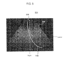
- the touch panel 161 may be configured to display a first setup screen 231 (shown in FIG. 5 ) including an ultrasound image 310 and a first reference line 410 .
- the ultrasound image 310 is based on the echo signal, the TGC and LGC of which are controlled based on the predetermined TGC and LGC values.
- the first reference line 410 may be used to detect a TGC curve 510 inputted by the user.
- the touch panel may then display a second setup screen 232 (shown in FIG. 6 ) including the ultrasound image 310 and a second reference line 420 .
- the second reference lines 420 may be used to detect a LGC curve 520 inputted by the user.
- the touch panel 161 may be configured to display the second setup screen 232 before the first setup screen 231 .
- the touch panel 161 may be configured to display a setup screen 240 (shown in FIG. 7 ) including a virtual ultrasound image 330 and first and second reference lines 410 , 420 .
- the TGC/LGC setup processor 162 may be configured to detect TGC and LGC curves 510 , 520 inputted by the user on the touch panel 161 . The TGC/LGC setup processor 162 may then calculate new TGC and LGC values in consideration of the detected TGC and LGC curves and transmit the values to the signal processing unit 130 .
- the TGC/LGC setup processor 162 may be configured to establish a first group of lines 610 and a second group of lines 620 .
- the first group of lines 610 is perpendicular to a first reference line 410 and the lines in said group are equally spaced apart from each other.
- the second group of lines 620 is perpendicular to a second reference line 420 and the lines in this group are equally spaced apart from each other. If it is determined that a curve inputted by the user (such as the curve 510 ) intersects the first group of lines more often than the second group of lines, then the TGC/LGC setup processor 162 recognizes that the curve is a TGC curve.
- the TGC/LGC setup processor 162 recognizes that the curve is a LGC curve.
- the TGC/LGC setup processor 162 calculates the new TGC value corresponding to the TGC curve 510 based on the first reference line 410 . It also calculates the LUG value corresponding to the LUC curve 520 based on the second reference line 420 .
- the TGC value and the LGC value are transmitted to the signal processing unit 130 .
- the present invention allows the user to accurately control the TGC and LUG by using the TGC and LGC curves inputted into the touch panel, thereby improving operational accuracy and time. Further, the present invention reduces the size of the control panel to thereby improve the spatial efficiency.
Landscapes
- Health & Medical Sciences (AREA)
- Life Sciences & Earth Sciences (AREA)
- Engineering & Computer Science (AREA)
- Physics & Mathematics (AREA)
- General Health & Medical Sciences (AREA)
- Nuclear Medicine, Radiotherapy & Molecular Imaging (AREA)
- Medical Informatics (AREA)
- Radiology & Medical Imaging (AREA)
- Pathology (AREA)
- Heart & Thoracic Surgery (AREA)
- Molecular Biology (AREA)
- Veterinary Medicine (AREA)
- Public Health (AREA)
- Biomedical Technology (AREA)
- Animal Behavior & Ethology (AREA)
- Biophysics (AREA)
- Surgery (AREA)
- General Physics & Mathematics (AREA)
- Theoretical Computer Science (AREA)
- General Engineering & Computer Science (AREA)
- Human Computer Interaction (AREA)
- Radar, Positioning & Navigation (AREA)
- Remote Sensing (AREA)
- Computer Networks & Wireless Communication (AREA)
- Computer Vision & Pattern Recognition (AREA)
- Quality & Reliability (AREA)
- Chemical & Material Sciences (AREA)
- Analytical Chemistry (AREA)
- Biochemistry (AREA)
- Immunology (AREA)
- Ultra Sonic Daignosis Equipment (AREA)
Abstract
The present invention provides an ultrasound system, which comprises: a signal acquiring unit to transmit an ultrasound signal to an object and acquire an echo signal reflected from the object; a signal processing unit to control TGC (Time Gain Compensation) and LGC (Lateral Gain Compensation) of the echo signal; a TGC/LGC setup unit adapted to set TGC and LGC values based on TGC and LGC curves inputted by a user; and an image producing unit adapted to produce an ultrasound image of the object based on the echo signal. The signal processing unit is further adapted to control the TGC and the LGC of the echo signal based on the TGC and LGC values set by the TGC/LGC setup unit.
Description
The present application is a Continuation of U.S. application Ser. No. 13/184,094, filed on Jul. 15, 2011, now U.S. Pat. No. 8,403,855 which is a Continuation of U.S. application Ser. No. 11/857,860, filed on Sep. 19, 2007, now U.S. Pat. No. 8,016,759, which claims priority from Korean Patent Application No. 10-2006-0123752 filed on Dec. 7, 2006, the entire subject matter of each of which is incorporated herein by reference.
1. Field
The present invention generally relates to an ultrasound system, and more particularly to an ultrasound system adapted to precisely and easily perform TGC (Time Gain Compensation) and LGC (Lateral Gain Compensation).
2. Background
An ultrasound system has become an important and popular diagnostic tool since it has a wide range of applications. Specifically, due to its non-invasive and non-destructive nature, the ultrasound system has been extensively used in the medical profession. Modern high-performance ultrasound systems and techniques are commonly used to produce two or three-dimensional diagnostic images of internal features of an object.
In order to transmit and receive ultrasound signals, the ultrasound system is generally provided with a probe including a wideband transducer. When the transducer is electrically stimulated, it produces ultrasound signals and transmits them into a human body. The ultrasound signals transmitted into the human body are reflected from borders between human tissues and then returned to the transducer. The returned ultrasound echo signals are converted into electric signals. Thereafter, ultrasound image data for imaging the tissues is produced by amplifying and signal-processing the echo signals.
Typically, the ultrasound system is provided with a control panel including a plurality of input units in order to perform a control function of acquiring the ultrasound image, a menu control function, a measurement and annotation function, etc. The control panel is comprised of a touch panel, an image control unit, a measurement control unit, etc. The touch panel displays menus for optimizing an ultrasound image displayed on a display unit. The menus on the touch panel can be touched and selected by a user. The image control unit controls the ultrasound image, whereas the measurement control unit measures a distance to the object, a circumference of the object, etc. As illustrated in FIG. 1 , the image control unit includes a plurality of TGC control keys 11 and a plurality of LGC control keys 12. The TGC control keys 11 are used to control a gain of each echo signal based on depth of the position from which the echo signal is reflected. Further, since the echo signal is attenuated at the outer right and left sides, the LGC control keys 12 are used to control a gain of the attenuated echo signal.
In the conventional system, the TGC control keys 11 and the LGC control keys 12 are arranged on different areas of the control panel. The problem associated with such an arrangement is that the size of the control panel must be inevitably increased. Further, a user of the system suffers a great inconvenience when operating the TGC control keys 11 and the LGC control keys 12. Another problem of the conventional system is that since the TGC control keys 11 and the LGC control keys 12 are comprised of slide-type variable resistors, it is very difficult for an unskilled user to finely control TGC and LGC with the TGC control keys 11 and the LGC control keys 12.
In order to resolve the above problems, the present invention is directed to providing an ultrasound system adapted to display a setup screen used to input TGC and LGC curves on a touch panel and perform TGC and LGC based on the inputted TGC and LGC curves.
The present invention provides an ultrasound system, which comprises: a signal acquiring unit adapted to transmit an ultrasound signal to an object and acquire an echo signal reflected from the object; a signal processing unit adapted to perform TGC (Time Gain Compensation) and LGC (Lateral Gain Compensation) upon the echo signal at a coarse compensation mode based on predetermined TGC and LGC values; an image producing unit adapted to produce an ultrasound image of the object based on the TGC and LGC compensated echo signal; an input unit adapted to allow a user to provide TGC and LGC curves; and a TGC/LGC setup processor adapted to set TGC and LGC values based on the TGC and LGC curves provided by the user. The signal processing unit is further adapted to perform the TGC and LGC upon the echo signal at a fine compensation mode based on the TGC and LGC values set by the TGC/LGC setup processor.
In addition, the present invention provides an ultrasound system, which comprises: a processor adapted to configure a setup screen for display; and a touch panel adapted to display the setup screen so as to allow a user to input TGC and LGC curves. The processor is further adapted to calculate the TGC and LGC values based on the inputted TGC and the LGC curves.
Arrangements and embodiments may be described in detail with reference to the following drawings in which like reference numerals refer to like elements and wherein:
A detailed description may be provided with reference to the accompanying drawings. One of ordinary skill in the art may realize that the following description is illustrative only and is not in any way limiting. Other embodiments of the present invention may readily suggest themselves to such skilled persons having the benefit of this disclosure.
Certain embodiments of the present invention will be explained below with reference to FIGS. 2 to 8 .
As illustrated in FIG. 2 , an ultrasound system 100 comprises: a probe 110; a beam former 120; a signal processing unit 130; a processor 140; a display unit 150; and a TGC/LGC setup unit 160. The probe 110 includes a plurality of transducers 112. Each of the transducers 112 may be configured to transmit an ultrasound signal to an object and receive the ultrasound signal reflected from the object. The beam former 120 may be configured to focus the transmitted ultrasound signals from the transducers 112 on the object and collect the reflected ultrasound signals from the object to the transducers 112 together with corresponding time delay.
The signal processing unit 130 may be configured to amplify the signals collected by the beam former 120 and control gains of the amplified echo signals. Specifically, the signal processing unit 130 may be configured to perform TGC (Time Gain Compensation) and LGC (Lateral Gain Compensation) upon the echo signals based on predetermined TGC and LGC values at a coarse compensation mode (e.g., in an initial operation stage). The signal processing unit 130 may be further configured to perform TGC and LGC upon the echo signals based on TGC and LGC values calculated in a TGC/LGC setup unit 160 using a curve inputted by a user at a fine compensation mode (e.g., during operations).
The processor 140 may be configured to receive the echo signals from the signal processing unit 130 and produce an ultrasound image signal based on the echo signals. The display unit 150 may be adapted to receive the ultrasound image signal from the processor and display an ultrasound image based on the signal.
The TGC/LGC setup unit 160 may include a touch panel 161 and a TGC/LGC setup processor 162.
The touch panel 161 may be configured to display a setup screen and detect TGC/LGC curves inputted by the user on the touch panel 161 to produce a detecting signal. The touch panel 161 detects the user's input according to either the pressure sensing method or the electromagnetic induction method. The touch panel 161 may be a touch panel included in a control panel (not shown) of the ultrasound system 100. Alternatively, it may be separate and apart from the ultrasound system 100.
In one embodiment of the present invention, the touch panel 161 may be configured to display a setup screen 210 (shown in FIG. 3 ) including an ultrasound image 310 and first and second reference lines 410, 420. The ultrasound image 310 is based on the echo signal, the TGC and LGC of which are controlled based on the predetermined TGC and LGC values. The first and second reference lines 410, 420 may be used to detect a TGC curve 510 and a LGC curve 520 inputted by the user (i.e., to determine whether a curve inputted by the user is a TGC curve 510 or a LGC curve 520). After inputting a curve, the user can modify a portion of the curve.
In another embodiment of the present invention, the touch panel 161 may be configured to display a setup screen 220 (shown in FIG. 4 ) including first and second ultrasound images 311, 312 and first and second reference lines 410, 420. The first and second ultrasound images 311, 312 are based on the echo signal, the TGC and LGC of which are controlled based on the predetermined TGC and LGC values. The first and second reference lines 410, 420 may be used to detect whether a curve inputted by the user is a TGC curve 510 or a LGC curve 520. The first ultrasound image 311 may be identical to the second initial ultrasound image 312.
In yet another embodiment of the present invention, the touch panel 161 may be configured to display a first setup screen 231 (shown in FIG. 5 ) including an ultrasound image 310 and a first reference line 410. The ultrasound image 310 is based on the echo signal, the TGC and LGC of which are controlled based on the predetermined TGC and LGC values. The first reference line 410 may be used to detect a TGC curve 510 inputted by the user. The touch panel may then display a second setup screen 232 (shown in FIG. 6 ) including the ultrasound image 310 and a second reference line 420. The second reference lines 420 may be used to detect a LGC curve 520 inputted by the user. Alternatively, the touch panel 161 may be configured to display the second setup screen 232 before the first setup screen 231.
In still yet another embodiment of the present invention, the touch panel 161 may be configured to display a setup screen 240 (shown in FIG. 7 ) including a virtual ultrasound image 330 and first and second reference lines 410, 420.
The TGC/LGC setup processor 162 may be configured to detect TGC and LGC curves 510, 520 inputted by the user on the touch panel 161. The TGC/LGC setup processor 162 may then calculate new TGC and LGC values in consideration of the detected TGC and LGC curves and transmit the values to the signal processing unit 130.
In one embodiment of the present invention, as illustrated in FIG. 8 , the TGC/LGC setup processor 162 may be configured to establish a first group of lines 610 and a second group of lines 620. The first group of lines 610 is perpendicular to a first reference line 410 and the lines in said group are equally spaced apart from each other. The second group of lines 620 is perpendicular to a second reference line 420 and the lines in this group are equally spaced apart from each other. If it is determined that a curve inputted by the user (such as the curve 510) intersects the first group of lines more often than the second group of lines, then the TGC/LGC setup processor 162 recognizes that the curve is a TGC curve. Alternatively, if it is determined that a curve inputted by the user (such as the curve 520) intersects the second group of lines more often than the first group of lines, then the TGC/LGC setup processor 162 recognizes that the curve is a LGC curve. The TGC/LGC setup processor 162 then calculates the new TGC value corresponding to the TGC curve 510 based on the first reference line 410. It also calculates the LUG value corresponding to the LUC curve 520 based on the second reference line 420. The TGC value and the LGC value are transmitted to the signal processing unit 130.
The present invention allows the user to accurately control the TGC and LUG by using the TGC and LGC curves inputted into the touch panel, thereby improving operational accuracy and time. Further, the present invention reduces the size of the control panel to thereby improve the spatial efficiency.
Although the present invention has been described with reference to a number of preferred embodiments thereof, it should be understood that numerous other modifications and embodiments can be devised by those skilled in the art that will fall within the spirit and scope of the principles of this disclosure. More particularly, numerous variations and modifications are possible in the component parts and/or arrangements of the subject combination arrangement within the scope of the disclosure, the drawings and the appended claims. In addition to variations and modifications in the component parts and/or arrangements, alternative uses will also be apparent to those skilled in the art.
Claims (30)
1. An ultrasound system, comprising:
a probe configured for transmitting an ultrasound signal to an object and receiving an echo signal reflected from the object;
a touch panel configured for receiving a touch input, the touch input comprising a plurality of touch input points including a first touch input point and a second touch input point; and
a processor configured for determining a first compensation value and a second compensation value at different depths corresponding to the first touch input point and the second touch input point, performing compensation on the echo signal based on the determined first compensation value and second compensation value and generating an ultrasound image of the object based on the compensated echo signal,
wherein the first touch input point and the second touch input point for setting the first compensation value and the second compensation value are received via a single touch input forming a single curve corresponding to different depths, and
wherein the first touch input point and the second touch input point correspond to two different depths on the generated ultrasound image.
2. The ultrasound system of claim 1 , wherein the generated ultrasound image is displayed on the touch panel.
3. The ultrasound system of claim 2 ,
wherein the generated ultrasound image is displayed on a first region of the touch panel and the touch input is received on a second region of the touch panel different from the first region.
4. The ultrasound system of claim 2 , wherein the touch input is received on the generated ultrasound image displayed on the touch panel.
5. The ultrasound system of claim 1 , wherein the generated ultrasound image is not displayed on the touch panel.
6. The ultrasound system of claim 1 , further comprising a display separate from the touch panel, wherein the generated ultrasound image is displayed on at least one of the display and touch panel.
7. The ultrasound system of claim 1 , further comprising a display configured for displaying the generated ultrasound image.
8. The ultrasound system of claim 7 , wherein a compensation line corresponding to the touch input is displayed on at least one of the touch panel and the display.
9. The ultrasound system of claim 8 , wherein the compensation line corresponding to the touch input is a Time Gain Compensation (TGC) line, representing gains of the echo signal with change of depths of the positions from which the echo signal is reflected, or a Lateral Gain Compensation (LGC) line, representing gains of the echo signal with lateral change of the positions from which the echo signal is reflected.
10. The ultrasound system of claim 9 , wherein the compensation is a TGC or a LGC depending upon whether the received compensation line is the TGC line or the LGC line.
11. The ultrasound system of claim 10 , wherein the processor is further configured to perform a second TGC or LGC on the echo signal at a coarse compensation mode based on a predetermined TGC or LGC value before the processor's performing of compensation.
12. The ultrasound system of claim 9 , wherein the processor causes the touch panel to display a first reference line and a second reference line, which are perpendicular to each other, to determine whether the compensation line is a TGC line or a LGC line.
13. The ultrasound system of claim 12 , wherein the processor is further configured to cause the touch panel to further display a first group of lines perpendicular to the first reference line, each of which is spaced apart from adjacent lines at a first uniform distance, and a second group of lines perpendicular to the second reference line, each of which is spaced apart from adjacent lines at a second uniform distance.
14. The ultrasound system of claim 13 , wherein the processor is further configured to determine that the received compensation line is a TGC line when the received compensation line intersects the first group of lines more than the second group of lines, and the processor is further configured to determine that the received compensation line is a LGC line when the received compensation line intersect the second group of lines more than the second group of lines more than the first group of lines.
15. The ultrasound system of claim 14 , wherein the processor is further configured to calculate a new TGC value based on the received compensation line and the first reference line if the received compensation line is the TGC, and the processor is further configured to calculate a new LGC value based on the received compensation line and the second reference line, if the received compensation line is the LGC line.
16. The ultrasound system of claim 15 , wherein the processor is further configured to perform compensation of the echo signal based on the new TGC value or the new LGC value.
17. An ultrasound system, comprising:
a probe configured for transmitting an ultrasound signal to an object and receiving an echo signal reflected from the object;
a display configured for displaying an ultrasound image of the object, the display including touch panel configured for receiving a touch input, the touch input comprising a plurality of touch input points including a first touch input point and a second touch input point; and
a processor configured for determining a first compensation value and a second compensation value at different depths corresponding to the first touch input point and the second touch input point, performing compensation on the echo signal based on the determined first compensation value and second compensation value and generating the ultrasound image of the object based on the compensated echo signal,
wherein the first touch input point and the second touch input point for setting the first compensation value and the second compensation value are received via a single touch input forming a single curve corresponding to different depths, and
wherein the first touch input point and the second touch input point correspond to two different depths on the generated ultrasound image.
18. The ultrasound system of claim 17 , wherein a compensation line corresponding to the touch input is not displayed on the touch panel and is displayed on the ultrasound image on the display.
19. The ultrasound system of claim 17 , wherein a compensation line corresponding to the touch input is on the area where the ultrasound image is displayed.
20. The ultrasound system of claim 17 , wherein a compensation line corresponding to the touch input is a Time Gain Compensation (TGC) line, representing gains of the echo signal with change of depths of the positions from which the echo signal is reflected, or a Lateral Gain Compensation (LGC) line, representing gains of the echo signal with lateral change of the positions from which the echo signal is reflected.
21. The ultrasound system of claim 20 , wherein the compensation is a TGC or a LGC depending upon whether the received compensation line is the TGC line or the LGC line.
22. The ultrasound system of claim 21 , wherein the processor is further configured to perform a second TGC or LGC on the echo signal at a coarse compensation mode based on a predetermined TGC or LGC value before the processor's performing of compensation.
23. The ultrasound system of claim 20 , wherein the processor is further configured to cause the touch panel to display a first reference line and a second reference line, which are perpendicular to each other, on the ultrasound image to determine whether the compensation line is a TGC line or a LGC line.
24. The ultrasound system of claim 23 , wherein the processor is further configured to cause the touch panel to further display a first group of lines perpendicular to the first reference line, each of which is spaced apart from adjacent lines at a first uniform distance, and a second group of lines perpendicular to the second reference line, each of which is spaced apart from adjacent lines at a second uniform distance.
25. The ultrasound system of claim 24 , wherein the processor is further configured to determine that the received compensation line is a TGC line when the received compensation line intersects the first group of lines more than the second group of lines, and the processor is further configured to determine that the received compensation line is a LGC line when the received compensation line intersect the second group of lines more than the second group of lines more than the first group of lines.
26. The ultrasound system of claim 25 , wherein the processor is further configured to calculate a new TGC value based on the received compensation line and the first reference line if the received compensation line is the TGC, and the processor is further configured to calculate a new LGC value based on the received compensation line and the second reference line, if the received compensation line is the LGC line.
27. The ultrasound system of claim 26 , wherein the processor is further configured to compensate the echo signal based on the new TGC value or the new LGC value.
28. The ultrasound system of claim 17 , wherein the touch panel is separately located from the display.
29. The ultrasound system of claim 1 , wherein the processor is configured to cause the touch panel to display multiple reference lines corresponding to different depths, and the first compensation value and the second compensation value are compensation values at points where the single curve intersects two of the multiple reference lines.
30. The ultrasound system of claim 17 , wherein the processor is configured to cause the touch panel to display multiple reference lines corresponding to different depths, and the first compensation value and the second compensation value are compensation values at points where the single curve intersects two of the multiple reference lines.
Priority Applications (1)
| Application Number | Priority Date | Filing Date | Title |
|---|---|---|---|
| US13/475,686 US9055920B2 (en) | 2006-12-07 | 2012-05-18 | Ultrasound system and signal processing unit configured for time gain and lateral gain compensation |
Applications Claiming Priority (6)
| Application Number | Priority Date | Filing Date | Title |
|---|---|---|---|
| KR10-2006-0123752 | 2006-12-07 | ||
| KR20060123752A KR100936456B1 (en) | 2006-12-07 | 2006-12-07 | Ultrasound system |
| KR10-2006-123752 | 2006-12-07 | ||
| US11/857,860 US8016759B2 (en) | 2006-12-07 | 2007-09-19 | Ultrasound system and signal processing unit configured for time gain and lateral gain compensation |
| US13/184,094 US8403855B2 (en) | 2006-12-07 | 2011-07-15 | Ultrasound system and signal processing unit configured for time gain and lateral gain compensation |
| US13/475,686 US9055920B2 (en) | 2006-12-07 | 2012-05-18 | Ultrasound system and signal processing unit configured for time gain and lateral gain compensation |
Related Parent Applications (1)
| Application Number | Title | Priority Date | Filing Date |
|---|---|---|---|
| US13/184,094 Continuation US8403855B2 (en) | 2006-12-07 | 2011-07-15 | Ultrasound system and signal processing unit configured for time gain and lateral gain compensation |
Publications (2)
| Publication Number | Publication Date |
|---|---|
| US20120232393A1 US20120232393A1 (en) | 2012-09-13 |
| US9055920B2 true US9055920B2 (en) | 2015-06-16 |
Family
ID=39156308
Family Applications (9)
| Application Number | Title | Priority Date | Filing Date |
|---|---|---|---|
| US11/857,860 Active 2030-06-16 US8016759B2 (en) | 2006-12-07 | 2007-09-19 | Ultrasound system and signal processing unit configured for time gain and lateral gain compensation |
| US13/184,094 Active US8403855B2 (en) | 2006-12-07 | 2011-07-15 | Ultrasound system and signal processing unit configured for time gain and lateral gain compensation |
| US13/475,686 Active US9055920B2 (en) | 2006-12-07 | 2012-05-18 | Ultrasound system and signal processing unit configured for time gain and lateral gain compensation |
| US13/756,274 Active 2034-03-30 US10321891B2 (en) | 2006-12-07 | 2013-01-31 | Ultrasound system and signal processing unit configured for time gain and lateral gain compensation |
| US13/938,847 Active US9259209B2 (en) | 2006-12-07 | 2013-07-10 | Ultrasound system and signal processing unit configured for time gain and lateral gain compensation |
| US14/866,038 Active US9833220B2 (en) | 2006-12-07 | 2015-09-25 | Ultrasound system configured for lateral gain compensation |
| US15/945,313 Pending US20230165566A9 (en) | 2006-12-07 | 2018-04-04 | Ultrasound system and signal processor configured for time gain and lateral gain compensation |
| US17/723,111 Active US11633174B2 (en) | 2006-12-07 | 2022-04-18 | Ultrasound system and signal processing unit configured for Time Gain and Lateral Gain Compensation |
| US18/138,334 Pending US20230380807A1 (en) | 2006-12-07 | 2023-04-24 | Ultrasound system and signal processing unit configured for time gain and lateral gain compensation |
Family Applications Before (2)
| Application Number | Title | Priority Date | Filing Date |
|---|---|---|---|
| US11/857,860 Active 2030-06-16 US8016759B2 (en) | 2006-12-07 | 2007-09-19 | Ultrasound system and signal processing unit configured for time gain and lateral gain compensation |
| US13/184,094 Active US8403855B2 (en) | 2006-12-07 | 2011-07-15 | Ultrasound system and signal processing unit configured for time gain and lateral gain compensation |
Family Applications After (6)
| Application Number | Title | Priority Date | Filing Date |
|---|---|---|---|
| US13/756,274 Active 2034-03-30 US10321891B2 (en) | 2006-12-07 | 2013-01-31 | Ultrasound system and signal processing unit configured for time gain and lateral gain compensation |
| US13/938,847 Active US9259209B2 (en) | 2006-12-07 | 2013-07-10 | Ultrasound system and signal processing unit configured for time gain and lateral gain compensation |
| US14/866,038 Active US9833220B2 (en) | 2006-12-07 | 2015-09-25 | Ultrasound system configured for lateral gain compensation |
| US15/945,313 Pending US20230165566A9 (en) | 2006-12-07 | 2018-04-04 | Ultrasound system and signal processor configured for time gain and lateral gain compensation |
| US17/723,111 Active US11633174B2 (en) | 2006-12-07 | 2022-04-18 | Ultrasound system and signal processing unit configured for Time Gain and Lateral Gain Compensation |
| US18/138,334 Pending US20230380807A1 (en) | 2006-12-07 | 2023-04-24 | Ultrasound system and signal processing unit configured for time gain and lateral gain compensation |
Country Status (4)
| Country | Link |
|---|---|
| US (9) | US8016759B2 (en) |
| EP (1) | EP1929952B1 (en) |
| KR (1) | KR100936456B1 (en) |
| DE (1) | DE602007010404D1 (en) |
Families Citing this family (21)
| Publication number | Priority date | Publication date | Assignee | Title |
|---|---|---|---|---|
| US10456111B2 (en) | 2006-12-07 | 2019-10-29 | Samsung Medison Co., Ltd. | Ultrasound system and signal processing unit configured for time gain and lateral gain compensation |
| KR100936456B1 (en) | 2006-12-07 | 2010-01-13 | 주식회사 메디슨 | Ultrasound system |
| US8351666B2 (en) * | 2007-11-15 | 2013-01-08 | General Electric Company | Portable imaging system having a seamless form factor |
| US9877699B2 (en) | 2012-03-26 | 2018-01-30 | Teratech Corporation | Tablet ultrasound system |
| US10667790B2 (en) | 2012-03-26 | 2020-06-02 | Teratech Corporation | Tablet ultrasound system |
| KR101361048B1 (en) * | 2012-06-21 | 2014-02-12 | 화남전자 주식회사 | Illumination structure of slide variable resistance |
| US8951200B2 (en) | 2012-08-10 | 2015-02-10 | Chison Medical Imaging Co., Ltd. | Apparatuses and methods for computer aided measurement and diagnosis during ultrasound imaging |
| KR101630761B1 (en) | 2012-09-24 | 2016-06-15 | 삼성전자주식회사 | Ultrasound apparatus and method for providing information using the ultrasound apparatus |
| KR20140090283A (en) * | 2012-12-12 | 2014-07-17 | 삼성메디슨 주식회사 | Ultrasound apparatus and method for inputting information using the ultrasound apparatus |
| EP2865338A1 (en) * | 2013-10-24 | 2015-04-29 | Samsung Medison Co., Ltd. | Ultrasound diagnosis apparatus and time gain compensation (TGC) setting method performed by the ultrasound diagnosis apparatus |
| KR101604812B1 (en) | 2014-01-15 | 2016-03-18 | 삼성전자주식회사 | Medical image processing apparatus and medical image processing method thereof |
| KR102249528B1 (en) | 2014-04-01 | 2021-05-11 | 삼성메디슨 주식회사 | Method, apparatus and system for adjusting brightness of ultrasound image by using prestored gradation data set and images |
| US10338036B2 (en) | 2014-05-01 | 2019-07-02 | TecScan Systems Inc. | Method and apparatus for scanning a test object and correcting for gain |
| US10342516B2 (en) | 2014-09-24 | 2019-07-09 | General Electric Company | Adaptive ultrasound image optimization through automatic gain control adjustment |
| WO2016060475A1 (en) | 2014-10-15 | 2016-04-21 | Samsung Electronics Co., Ltd. | Method of providing information using plurality of displays and ultrasound apparatus therefor |
| KR102433401B1 (en) * | 2014-11-18 | 2022-08-17 | 삼성메디슨 주식회사 | Ultrasound imaging apparatus and control method for the same |
| EP3023059A1 (en) * | 2014-11-18 | 2016-05-25 | Samsung Medison Co., Ltd. | Ultrasound imaging apparatus and method of controlling the same |
| KR102418975B1 (en) | 2014-12-05 | 2022-07-08 | 삼성메디슨 주식회사 | Ultrasound apparatus and method for providing information |
| WO2018198327A1 (en) * | 2017-04-28 | 2018-11-01 | オリンパス株式会社 | Endoscope diagnosis assist system, endoscope diagnosis assist program, and endoscope diagnosis assist method |
| CN110327076B (en) * | 2019-07-05 | 2022-08-16 | 深圳开立生物医疗科技股份有限公司 | Blood flow gain adjusting method, device, equipment and readable storage medium |
| US11717967B2 (en) | 2021-03-04 | 2023-08-08 | TecScan Systems Inc. | System and method for scanning an object using an array of ultrasonic transducers |
Citations (34)
| Publication number | Priority date | Publication date | Assignee | Title |
|---|---|---|---|---|
| US4043181A (en) | 1975-04-18 | 1977-08-23 | New York Institute Of Technology | Ultrasonic pulse-echo apparatus |
| US4475400A (en) | 1982-07-16 | 1984-10-09 | General Electric Company | Method and means for improving image in an ultrasonic scanning system |
| US4817614A (en) * | 1986-08-20 | 1989-04-04 | Siemens Aktiengesellschaft | Method and apparatus for adaptive focusing in a medical ultrasound imaging apparatus |
| US5161535A (en) | 1991-06-24 | 1992-11-10 | Hewlett-Packard Company | Medical ultrasound imaging system having a partitioned menu |
| EP0539697A1 (en) | 1991-10-25 | 1993-05-05 | Hewlett-Packard Company | Gain control for ultrasound system |
| US5245586A (en) | 1991-11-15 | 1993-09-14 | Siemens Aktiengesellschaft | Apparatus and method for suppressing reflections at an ultrasound transducer |
| US5315999A (en) | 1993-04-21 | 1994-05-31 | Hewlett-Packard Company | Ultrasound imaging system having user preset modes |
| JPH06154227A (en) | 1992-11-20 | 1994-06-03 | Terumo Corp | Ultrasonic diagnosing apparatus |
| US5482045A (en) | 1994-10-12 | 1996-01-09 | Advanced Technology Laboratories, Inc. | Ultrasonic diagnostic system gain control |
| JPH10248843A (en) | 1997-03-11 | 1998-09-22 | Olympus Optical Co Ltd | Ultrasonograph device |
| JP2000197637A (en) | 1998-12-01 | 2000-07-18 | General Electric Co <Ge> | Method and device for automatic time and/or horizontal direction gain compensation in b mode ultrasonic imaging |
| US6142942A (en) | 1999-03-22 | 2000-11-07 | Agilent Technologies, Inc. | Ultrasound imaging system and method employing an adaptive filter |
| KR20010067091A (en) | 1999-08-23 | 2001-07-12 | 추후보정 | Method and apparatus for providing real-time calculation and display of tissue deformation in ultrasound imaging |
| US20020008692A1 (en) * | 1998-07-30 | 2002-01-24 | Katsuyuki Omura | Electronic blackboard system |
| EP1219972A2 (en) | 2000-12-28 | 2002-07-03 | GE Medical Systems Global Technology Company LLC | Time-gain controlling method and apparatus, recording medium and ultrasonic imaging apparatus |
| US6468212B1 (en) * | 1997-04-19 | 2002-10-22 | Adalberto Vara | User control interface for an ultrasound processor |
| US20030097071A1 (en) | 2001-11-21 | 2003-05-22 | Menachem Halmann | Method and system for PDA-based ultrasound system |
| US20030187353A1 (en) * | 2002-04-01 | 2003-10-02 | Gary Ng | Ultrasonic diagnostic imaging system with automatically controlled contrast and brightness |
| US20030236459A1 (en) | 2002-06-20 | 2003-12-25 | Loftman Rickard C. | Automatic gain compensation for multiple mode or contrast agent imaging |
| US6677985B1 (en) | 1998-03-06 | 2004-01-13 | Hitachi Medical Corporation | Ultrasonic video apparatus |
| US20040015079A1 (en) | 1999-06-22 | 2004-01-22 | Teratech Corporation | Ultrasound probe with integrated electronics |
| KR20040069378A (en) | 2003-01-29 | 2004-08-06 | 주식회사 메디슨 | Ultrasound imaging apparatus with transmit-focusing points selecting function and method therefor |
| US20050059892A1 (en) | 2003-09-17 | 2005-03-17 | Elizabeth Dubois | Method and system for lateral gain control in an ultrasound imaging system |
| US7022075B2 (en) | 1999-08-20 | 2006-04-04 | Zonare Medical Systems, Inc. | User interface for handheld imaging devices |
| KR20060033845A (en) | 2004-10-16 | 2006-04-20 | 화남전자 주식회사 | Control circuit for operating pannel of an ultrasonograph |
| JP2006296978A (en) | 2005-04-25 | 2006-11-02 | Toshiba Corp | Ultrasonic image diagnostic apparatus |
| US20070230759A1 (en) | 2006-03-31 | 2007-10-04 | Aloka Co., Ltd. | Methods and apparatus for ultrasound imaging |
| US20070239019A1 (en) | 2006-02-13 | 2007-10-11 | Richard William D | Portable ultrasonic imaging probe than connects directly to a host computer |
| US20090069677A1 (en) | 2007-09-11 | 2009-03-12 | Focus Surgery, Inc. | System and method for tissue change monitoring during hifu treatment |
| US20100145195A1 (en) | 2008-12-08 | 2010-06-10 | Dong Gyu Hyun | Hand-Held Ultrasound System |
| US20110054325A1 (en) | 2009-08-31 | 2011-03-03 | Medison Co., Ltd. | Steering angle adjustment of scan lines using virtual transducer elements in an ultrasound system |
| US8016759B2 (en) * | 2006-12-07 | 2011-09-13 | Medison Co., Ltd. | Ultrasound system and signal processing unit configured for time gain and lateral gain compensation |
| US20130064036A1 (en) * | 2006-12-07 | 2013-03-14 | Doo Sik LEE | Ultrasound system and signal processing unit configured for time gain and lateral gain compensation |
| US20140088428A1 (en) * | 2012-09-24 | 2014-03-27 | Samsung Medison Co., Ltd. | Ultrasound apparatus and information providing method of the ultrasound apparatus |
Family Cites Families (24)
| Publication number | Priority date | Publication date | Assignee | Title |
|---|---|---|---|---|
| AU1294995A (en) * | 1993-11-29 | 1995-06-19 | Perception, Inc. | Pc based ultrasound device with virtual control user interface |
| US6575908B2 (en) * | 1996-06-28 | 2003-06-10 | Sonosite, Inc. | Balance body ultrasound system |
| US6261234B1 (en) * | 1998-05-07 | 2001-07-17 | Diasonics Ultrasound, Inc. | Method and apparatus for ultrasound imaging with biplane instrument guidance |
| US6368279B1 (en) | 2000-09-15 | 2002-04-09 | Siemens Medical Solutions, Usa Inc. | Time-delay compensation system and method for adaptive ultrasound imaging |
| US7066887B2 (en) * | 2003-10-21 | 2006-06-27 | Vermon | Bi-plane ultrasonic probe |
| US20060020204A1 (en) * | 2004-07-01 | 2006-01-26 | Bracco Imaging, S.P.A. | System and method for three-dimensional space management and visualization of ultrasound data ("SonoDEX") |
| WO2006040697A1 (en) * | 2004-10-12 | 2006-04-20 | Koninklijke Philips Electronics, N.V. | Ultrasound touchscreen user interface and display |
| AU2008314498A1 (en) * | 2007-10-16 | 2009-04-23 | Signostics Limited | Medical diagnostic device user interface |
| FR2928257B1 (en) * | 2008-03-04 | 2011-01-14 | Super Sonic Imagine | ELECTRONIC SYSTEM FOR DOUBLE SCREEN DISPLAY. |
| US9408587B2 (en) | 2008-08-22 | 2016-08-09 | Ultrasonix Medical Corporation | Highly configurable medical ultrasound machine and related methods |
| WO2012071429A1 (en) * | 2010-11-26 | 2012-05-31 | Hologic, Inc. | User interface for medical image review workstation |
| JP5134721B1 (en) * | 2011-11-28 | 2013-01-30 | 株式会社東芝 | Portable ultrasound system |
| US9314225B2 (en) * | 2012-02-27 | 2016-04-19 | General Electric Company | Method and apparatus for performing ultrasound imaging |
| US9329690B2 (en) * | 2012-03-09 | 2016-05-03 | Schlumberger Technology Corporation | Multitouch control of petrotechnical software |
| US9024902B2 (en) | 2012-03-26 | 2015-05-05 | General Electric Company | Ultrasound device and method thereof |
| US20130324850A1 (en) * | 2012-05-31 | 2013-12-05 | Mindray Ds Usa, Inc. | Systems and methods for interfacing with an ultrasound system |
| KR20140090283A (en) * | 2012-12-12 | 2014-07-17 | 삼성메디슨 주식회사 | Ultrasound apparatus and method for inputting information using the ultrasound apparatus |
| EP2865338A1 (en) * | 2013-10-24 | 2015-04-29 | Samsung Medison Co., Ltd. | Ultrasound diagnosis apparatus and time gain compensation (TGC) setting method performed by the ultrasound diagnosis apparatus |
| KR101611443B1 (en) * | 2014-02-28 | 2016-04-11 | 삼성메디슨 주식회사 | Method for Controlling Ultrasound Imaging Apparatus and Ultrasound Imaging Apparatus Thereof |
| WO2016007673A2 (en) * | 2014-07-09 | 2016-01-14 | Edan Instruments, Inc. | Portable ultrasound user interface and resource management systems and methods |
| WO2016060475A1 (en) * | 2014-10-15 | 2016-04-21 | Samsung Electronics Co., Ltd. | Method of providing information using plurality of displays and ultrasound apparatus therefor |
| US10420533B2 (en) * | 2014-11-04 | 2019-09-24 | Samsung Electronics Co., Ltd. | Ultrasound diagnosis apparatus and control method thereof |
| EP3023059A1 (en) * | 2014-11-18 | 2016-05-25 | Samsung Medison Co., Ltd. | Ultrasound imaging apparatus and method of controlling the same |
| KR102635050B1 (en) | 2016-07-20 | 2024-02-08 | 삼성메디슨 주식회사 | Ultrasound imaging apparatus and control method for the same |
-
2006
- 2006-12-07 KR KR20060123752A patent/KR100936456B1/en active IP Right Grant
-
2007
- 2007-09-19 US US11/857,860 patent/US8016759B2/en active Active
- 2007-09-19 DE DE200760010404 patent/DE602007010404D1/en active Active
- 2007-09-19 EP EP20070018336 patent/EP1929952B1/en active Active
-
2011
- 2011-07-15 US US13/184,094 patent/US8403855B2/en active Active
-
2012
- 2012-05-18 US US13/475,686 patent/US9055920B2/en active Active
-
2013
- 2013-01-31 US US13/756,274 patent/US10321891B2/en active Active
- 2013-07-10 US US13/938,847 patent/US9259209B2/en active Active
-
2015
- 2015-09-25 US US14/866,038 patent/US9833220B2/en active Active
-
2018
- 2018-04-04 US US15/945,313 patent/US20230165566A9/en active Pending
-
2022
- 2022-04-18 US US17/723,111 patent/US11633174B2/en active Active
-
2023
- 2023-04-24 US US18/138,334 patent/US20230380807A1/en active Pending
Patent Citations (39)
| Publication number | Priority date | Publication date | Assignee | Title |
|---|---|---|---|---|
| US4043181A (en) | 1975-04-18 | 1977-08-23 | New York Institute Of Technology | Ultrasonic pulse-echo apparatus |
| US4475400A (en) | 1982-07-16 | 1984-10-09 | General Electric Company | Method and means for improving image in an ultrasonic scanning system |
| US4817614A (en) * | 1986-08-20 | 1989-04-04 | Siemens Aktiengesellschaft | Method and apparatus for adaptive focusing in a medical ultrasound imaging apparatus |
| US5161535A (en) | 1991-06-24 | 1992-11-10 | Hewlett-Packard Company | Medical ultrasound imaging system having a partitioned menu |
| EP0539697A1 (en) | 1991-10-25 | 1993-05-05 | Hewlett-Packard Company | Gain control for ultrasound system |
| US5245586A (en) | 1991-11-15 | 1993-09-14 | Siemens Aktiengesellschaft | Apparatus and method for suppressing reflections at an ultrasound transducer |
| JPH06154227A (en) | 1992-11-20 | 1994-06-03 | Terumo Corp | Ultrasonic diagnosing apparatus |
| US5315999A (en) | 1993-04-21 | 1994-05-31 | Hewlett-Packard Company | Ultrasound imaging system having user preset modes |
| US5482045A (en) | 1994-10-12 | 1996-01-09 | Advanced Technology Laboratories, Inc. | Ultrasonic diagnostic system gain control |
| JPH10248843A (en) | 1997-03-11 | 1998-09-22 | Olympus Optical Co Ltd | Ultrasonograph device |
| US6468212B1 (en) * | 1997-04-19 | 2002-10-22 | Adalberto Vara | User control interface for an ultrasound processor |
| US6677985B1 (en) | 1998-03-06 | 2004-01-13 | Hitachi Medical Corporation | Ultrasonic video apparatus |
| US20020008692A1 (en) * | 1998-07-30 | 2002-01-24 | Katsuyuki Omura | Electronic blackboard system |
| JP2000197637A (en) | 1998-12-01 | 2000-07-18 | General Electric Co <Ge> | Method and device for automatic time and/or horizontal direction gain compensation in b mode ultrasonic imaging |
| US6102859A (en) * | 1998-12-01 | 2000-08-15 | General Electric Company | Method and apparatus for automatic time and/or lateral gain compensation in B-mode ultrasound imaging |
| US6142942A (en) | 1999-03-22 | 2000-11-07 | Agilent Technologies, Inc. | Ultrasound imaging system and method employing an adaptive filter |
| US20040015079A1 (en) | 1999-06-22 | 2004-01-22 | Teratech Corporation | Ultrasound probe with integrated electronics |
| US7022075B2 (en) | 1999-08-20 | 2006-04-04 | Zonare Medical Systems, Inc. | User interface for handheld imaging devices |
| KR20010067091A (en) | 1999-08-23 | 2001-07-12 | 추후보정 | Method and apparatus for providing real-time calculation and display of tissue deformation in ultrasound imaging |
| EP1219972A2 (en) | 2000-12-28 | 2002-07-03 | GE Medical Systems Global Technology Company LLC | Time-gain controlling method and apparatus, recording medium and ultrasonic imaging apparatus |
| US6933934B2 (en) | 2000-12-28 | 2005-08-23 | Ge Medical Systems Global Technology Company, Llc | Time-gain controlling method and apparatus, recording medium and ultrasonic imaging apparatus |
| US20030097071A1 (en) | 2001-11-21 | 2003-05-22 | Menachem Halmann | Method and system for PDA-based ultrasound system |
| US20030187353A1 (en) * | 2002-04-01 | 2003-10-02 | Gary Ng | Ultrasonic diagnostic imaging system with automatically controlled contrast and brightness |
| US20030236459A1 (en) | 2002-06-20 | 2003-12-25 | Loftman Rickard C. | Automatic gain compensation for multiple mode or contrast agent imaging |
| KR20040069378A (en) | 2003-01-29 | 2004-08-06 | 주식회사 메디슨 | Ultrasound imaging apparatus with transmit-focusing points selecting function and method therefor |
| US20050059892A1 (en) | 2003-09-17 | 2005-03-17 | Elizabeth Dubois | Method and system for lateral gain control in an ultrasound imaging system |
| KR20060033845A (en) | 2004-10-16 | 2006-04-20 | 화남전자 주식회사 | Control circuit for operating pannel of an ultrasonograph |
| JP2006296978A (en) | 2005-04-25 | 2006-11-02 | Toshiba Corp | Ultrasonic image diagnostic apparatus |
| US20070239019A1 (en) | 2006-02-13 | 2007-10-11 | Richard William D | Portable ultrasonic imaging probe than connects directly to a host computer |
| US20130030298A1 (en) | 2006-03-31 | 2013-01-31 | Tadashi Tamura | Methods and apparatus for ultrasound imaging |
| US20070230759A1 (en) | 2006-03-31 | 2007-10-04 | Aloka Co., Ltd. | Methods and apparatus for ultrasound imaging |
| US20130144169A1 (en) * | 2006-07-12 | 2013-06-06 | Samsung Medison Co., Ltd. | Ultrasound system and signal processing unit configured for time gain and lateral gain compensation |
| US20130064036A1 (en) * | 2006-12-07 | 2013-03-14 | Doo Sik LEE | Ultrasound system and signal processing unit configured for time gain and lateral gain compensation |
| US8016759B2 (en) * | 2006-12-07 | 2011-09-13 | Medison Co., Ltd. | Ultrasound system and signal processing unit configured for time gain and lateral gain compensation |
| US8403855B2 (en) * | 2006-12-07 | 2013-03-26 | Samsung Medison Co., Ltd. | Ultrasound system and signal processing unit configured for time gain and lateral gain compensation |
| US20090069677A1 (en) | 2007-09-11 | 2009-03-12 | Focus Surgery, Inc. | System and method for tissue change monitoring during hifu treatment |
| US20100145195A1 (en) | 2008-12-08 | 2010-06-10 | Dong Gyu Hyun | Hand-Held Ultrasound System |
| US20110054325A1 (en) | 2009-08-31 | 2011-03-03 | Medison Co., Ltd. | Steering angle adjustment of scan lines using virtual transducer elements in an ultrasound system |
| US20140088428A1 (en) * | 2012-09-24 | 2014-03-27 | Samsung Medison Co., Ltd. | Ultrasound apparatus and information providing method of the ultrasound apparatus |
Non-Patent Citations (2)
| Title |
|---|
| United States Office Action issued in U.S. Appl. No. 13/938,847 dated Mar. 21, 2014. |
| United States Office Action issued in U.S. Appl. No. 13/938,847 dated Oct. 8, 2013. |
Also Published As
| Publication number | Publication date |
|---|---|
| US20130144169A1 (en) | 2013-06-06 |
| US20110276283A1 (en) | 2011-11-10 |
| US20130303911A1 (en) | 2013-11-14 |
| US20220233170A1 (en) | 2022-07-28 |
| US8016759B2 (en) | 2011-09-13 |
| EP1929952A1 (en) | 2008-06-11 |
| US10321891B2 (en) | 2019-06-18 |
| US20160007966A1 (en) | 2016-01-14 |
| KR100936456B1 (en) | 2010-01-13 |
| US20230165566A9 (en) | 2023-06-01 |
| US11633174B2 (en) | 2023-04-25 |
| US20180228472A1 (en) | 2018-08-16 |
| US9259209B2 (en) | 2016-02-16 |
| US20120232393A1 (en) | 2012-09-13 |
| DE602007010404D1 (en) | 2010-12-23 |
| US20080139932A1 (en) | 2008-06-12 |
| US9833220B2 (en) | 2017-12-05 |
| US20230380807A1 (en) | 2023-11-30 |
| EP1929952B1 (en) | 2010-11-10 |
| US8403855B2 (en) | 2013-03-26 |
| KR20080051917A (en) | 2008-06-11 |
Similar Documents
| Publication | Publication Date | Title |
|---|---|---|
| US11633174B2 (en) | Ultrasound system and signal processing unit configured for Time Gain and Lateral Gain Compensation | |
| US20130064036A1 (en) | Ultrasound system and signal processing unit configured for time gain and lateral gain compensation | |
| US7833159B2 (en) | Image processing system and method of enhancing the quality of an ultrasound image | |
| US9125589B2 (en) | System and method for tissue characterization using ultrasound imaging | |
| US8526669B2 (en) | Method for multiple image parameter adjustment based on single user input | |
| EP1780671B1 (en) | Image processing system and method for editing contours of a target object using multiple sectional images | |
| US20180132831A1 (en) | Ultrasound diagnosis apparatus and method of controlling the same | |
| EP1977694A1 (en) | Ultrasound system and method of forming an ultrasound image | |
| US20200237343A1 (en) | Ultrasound elasticity measuring devices and elasticity comparative measuring methods | |
| CN107440720A (en) | The bearing calibration of diagnostic ultrasound equipment and view data | |
| US11259777B2 (en) | Ultrasound diagnosis apparatus and medical image processing method | |
| US20100056920A1 (en) | Ultrasound system and method of providing orientation help view | |
| JPH06154227A (en) | Ultrasonic diagnosing apparatus | |
| JP3235973B2 (en) | Ultrasound diagnostic equipment | |
| CN111904462A (en) | Method and system for presenting functional data | |
| JP2815622B2 (en) | Ultrasound diagnostic equipment | |
| JP3188890U (en) | Ultrasonic observation system | |
| JP6705261B2 (en) | Image generating apparatus and image generating method | |
| JP2017184846A (en) | Image forming device and image forming method | |
| JP2018064933A (en) | Ultrasound diagnosis apparatus and program | |
| JP2001286470A (en) | Ultrasonic diagnostic apparatus | |
| JPH07171153A (en) | Ultrasonic diagnostic device |
Legal Events
| Date | Code | Title | Description |
|---|---|---|---|
| FEPP | Fee payment procedure |
Free format text: PAYOR NUMBER ASSIGNED (ORIGINAL EVENT CODE: ASPN); ENTITY STATUS OF PATENT OWNER: LARGE ENTITY |
|
| STCF | Information on status: patent grant |
Free format text: PATENTED CASE |
|
| MAFP | Maintenance fee payment |
Free format text: PAYMENT OF MAINTENANCE FEE, 4TH YEAR, LARGE ENTITY (ORIGINAL EVENT CODE: M1551); ENTITY STATUS OF PATENT OWNER: LARGE ENTITY Year of fee payment: 4 |
|
| MAFP | Maintenance fee payment |
Free format text: PAYMENT OF MAINTENANCE FEE, 8TH YEAR, LARGE ENTITY (ORIGINAL EVENT CODE: M1552); ENTITY STATUS OF PATENT OWNER: LARGE ENTITY Year of fee payment: 8 |