US9150803B2 - Systems and methods for biomass grinding and feeding - Google Patents
Systems and methods for biomass grinding and feeding Download PDFInfo
- Publication number
- US9150803B2 US9150803B2 US12/796,222 US79622210A US9150803B2 US 9150803 B2 US9150803 B2 US 9150803B2 US 79622210 A US79622210 A US 79622210A US 9150803 B2 US9150803 B2 US 9150803B2
- Authority
- US
- United States
- Prior art keywords
- biomass
- reactor
- particles
- feed
- flow
- Prior art date
- Legal status (The legal status is an assumption and is not a legal conclusion. Google has not performed a legal analysis and makes no representation as to the accuracy of the status listed.)
- Expired - Fee Related, expires
Links
- 239000002028 Biomass Substances 0.000 title claims abstract description 334
- 238000000034 method Methods 0.000 title claims abstract description 60
- 238000000227 grinding Methods 0.000 title description 23
- 239000002245 particle Substances 0.000 claims abstract description 170
- 239000000126 substance Substances 0.000 claims abstract description 95
- 238000002309 gasification Methods 0.000 claims abstract description 72
- 238000006243 chemical reaction Methods 0.000 claims abstract description 64
- 239000000446 fuel Substances 0.000 claims abstract description 49
- 230000008569 process Effects 0.000 claims abstract description 49
- 230000015572 biosynthetic process Effects 0.000 claims abstract description 36
- 238000003786 synthesis reaction Methods 0.000 claims abstract description 35
- UGFAIRIUMAVXCW-UHFFFAOYSA-N Carbon monoxide Chemical compound [O+]#[C-] UGFAIRIUMAVXCW-UHFFFAOYSA-N 0.000 claims abstract description 31
- 229910002091 carbon monoxide Inorganic materials 0.000 claims abstract description 31
- 239000012159 carrier gas Substances 0.000 claims abstract description 31
- 229910052739 hydrogen Inorganic materials 0.000 claims abstract description 31
- 239000001257 hydrogen Substances 0.000 claims abstract description 31
- UFHFLCQGNIYNRP-UHFFFAOYSA-N Hydrogen Chemical compound [H][H] UFHFLCQGNIYNRP-UHFFFAOYSA-N 0.000 claims abstract description 30
- 239000004215 Carbon black (E152) Substances 0.000 claims abstract description 19
- 229930195733 hydrocarbon Natural products 0.000 claims abstract description 19
- 150000002430 hydrocarbons Chemical class 0.000 claims abstract description 19
- 239000007788 liquid Substances 0.000 claims abstract description 11
- 239000007789 gas Substances 0.000 claims description 42
- 239000000047 product Substances 0.000 claims description 40
- OKKJLVBELUTLKV-UHFFFAOYSA-N Methanol Chemical compound OC OKKJLVBELUTLKV-UHFFFAOYSA-N 0.000 claims description 28
- 239000000463 material Substances 0.000 claims description 20
- 239000002699 waste material Substances 0.000 claims description 19
- VYPSYNLAJGMNEJ-UHFFFAOYSA-N Silicium dioxide Chemical compound O=[Si]=O VYPSYNLAJGMNEJ-UHFFFAOYSA-N 0.000 claims description 15
- CURLTUGMZLYLDI-UHFFFAOYSA-N Carbon dioxide Chemical compound O=C=O CURLTUGMZLYLDI-UHFFFAOYSA-N 0.000 claims description 12
- 239000000203 mixture Substances 0.000 claims description 11
- 238000002347 injection Methods 0.000 claims description 10
- 239000007924 injection Substances 0.000 claims description 10
- 239000002918 waste heat Substances 0.000 claims description 10
- 238000009826 distribution Methods 0.000 claims description 9
- 230000008859 change Effects 0.000 claims description 8
- 235000013305 food Nutrition 0.000 claims description 7
- 229910002092 carbon dioxide Inorganic materials 0.000 claims description 6
- 230000006835 compression Effects 0.000 claims description 6
- 238000007906 compression Methods 0.000 claims description 6
- 230000009467 reduction Effects 0.000 claims description 6
- 239000000377 silicon dioxide Substances 0.000 claims description 6
- 239000007795 chemical reaction product Substances 0.000 claims description 5
- 239000001569 carbon dioxide Substances 0.000 claims description 4
- 238000004519 manufacturing process Methods 0.000 claims description 4
- 238000010298 pulverizing process Methods 0.000 claims description 4
- 238000010521 absorption reaction Methods 0.000 claims description 3
- 239000006185 dispersion Substances 0.000 claims description 3
- 229910021485 fumed silica Inorganic materials 0.000 claims description 3
- 230000005855 radiation Effects 0.000 claims description 3
- 238000000197 pyrolysis Methods 0.000 claims description 2
- 239000003623 enhancer Substances 0.000 claims 4
- 238000010586 diagram Methods 0.000 description 15
- VNWKTOKETHGBQD-UHFFFAOYSA-N methane Chemical compound C VNWKTOKETHGBQD-UHFFFAOYSA-N 0.000 description 13
- 241000209094 Oryza Species 0.000 description 12
- 235000007164 Oryza sativa Nutrition 0.000 description 12
- 235000009566 rice Nutrition 0.000 description 12
- 239000010902 straw Substances 0.000 description 12
- 238000013461 design Methods 0.000 description 8
- 238000003860 storage Methods 0.000 description 8
- 239000007787 solid Substances 0.000 description 7
- 241000878007 Miscanthus Species 0.000 description 6
- 239000011269 tar Substances 0.000 description 6
- 241000196324 Embryophyta Species 0.000 description 5
- 241001520808 Panicum virgatum Species 0.000 description 5
- 240000008042 Zea mays Species 0.000 description 5
- 235000005824 Zea mays ssp. parviglumis Nutrition 0.000 description 5
- 235000002017 Zea mays subsp mays Nutrition 0.000 description 5
- 230000001276 controlling effect Effects 0.000 description 5
- 235000005822 corn Nutrition 0.000 description 5
- 125000004122 cyclic group Chemical group 0.000 description 5
- 238000000280 densification Methods 0.000 description 5
- 239000010907 stover Substances 0.000 description 5
- 230000005611 electricity Effects 0.000 description 4
- OKTJSMMVPCPJKN-UHFFFAOYSA-N Carbon Chemical compound [C] OKTJSMMVPCPJKN-UHFFFAOYSA-N 0.000 description 3
- 240000006394 Sorghum bicolor Species 0.000 description 3
- 235000011684 Sorghum saccharatum Nutrition 0.000 description 3
- 241000209140 Triticum Species 0.000 description 3
- 235000021307 Triticum Nutrition 0.000 description 3
- 150000001412 amines Chemical group 0.000 description 3
- 229910052799 carbon Inorganic materials 0.000 description 3
- 230000000875 corresponding effect Effects 0.000 description 3
- -1 e.g. Substances 0.000 description 3
- 230000000694 effects Effects 0.000 description 3
- 238000010438 heat treatment Methods 0.000 description 3
- 239000002420 orchard Substances 0.000 description 3
- 239000002253 acid Substances 0.000 description 2
- 230000009471 action Effects 0.000 description 2
- 230000003197 catalytic effect Effects 0.000 description 2
- 238000005520 cutting process Methods 0.000 description 2
- 229920005610 lignin Polymers 0.000 description 2
- 238000011068 loading method Methods 0.000 description 2
- 238000012986 modification Methods 0.000 description 2
- 230000004048 modification Effects 0.000 description 2
- 239000003345 natural gas Substances 0.000 description 2
- 239000011164 primary particle Substances 0.000 description 2
- 239000002994 raw material Substances 0.000 description 2
- 238000007670 refining Methods 0.000 description 2
- 244000025254 Cannabis sativa Species 0.000 description 1
- LFQSCWFLJHTTHZ-UHFFFAOYSA-N Ethanol Chemical compound CCO LFQSCWFLJHTTHZ-UHFFFAOYSA-N 0.000 description 1
- 230000002411 adverse Effects 0.000 description 1
- 239000000443 aerosol Substances 0.000 description 1
- 238000013528 artificial neural network Methods 0.000 description 1
- 230000004888 barrier function Effects 0.000 description 1
- 230000008901 benefit Effects 0.000 description 1
- 238000012993 chemical processing Methods 0.000 description 1
- 238000012824 chemical production Methods 0.000 description 1
- 239000003795 chemical substances by application Substances 0.000 description 1
- 238000002485 combustion reaction Methods 0.000 description 1
- 238000004891 communication Methods 0.000 description 1
- 238000005094 computer simulation Methods 0.000 description 1
- 238000010924 continuous production Methods 0.000 description 1
- 230000002596 correlated effect Effects 0.000 description 1
- 230000001186 cumulative effect Effects 0.000 description 1
- 238000010790 dilution Methods 0.000 description 1
- 239000012895 dilution Substances 0.000 description 1
- 235000021186 dishes Nutrition 0.000 description 1
- 238000005516 engineering process Methods 0.000 description 1
- 238000002474 experimental method Methods 0.000 description 1
- 239000012530 fluid Substances 0.000 description 1
- 230000006870 function Effects 0.000 description 1
- 230000014509 gene expression Effects 0.000 description 1
- 150000002431 hydrogen Chemical class 0.000 description 1
- 230000007246 mechanism Effects 0.000 description 1
- 238000003801 milling Methods 0.000 description 1
- 230000003287 optical effect Effects 0.000 description 1
- 230000001590 oxidative effect Effects 0.000 description 1
- 238000005453 pelletization Methods 0.000 description 1
- 238000002360 preparation method Methods 0.000 description 1
- 238000010926 purge Methods 0.000 description 1
- 238000010791 quenching Methods 0.000 description 1
- 230000000171 quenching effect Effects 0.000 description 1
- 230000009257 reactivity Effects 0.000 description 1
- 229920005989 resin Polymers 0.000 description 1
- 239000011347 resin Substances 0.000 description 1
- 238000005549 size reduction Methods 0.000 description 1
- 239000002002 slurry Substances 0.000 description 1
- 238000012360 testing method Methods 0.000 description 1
- 238000012546 transfer Methods 0.000 description 1
- 238000011144 upstream manufacturing Methods 0.000 description 1
Images


Classifications
-
- C—CHEMISTRY; METALLURGY
- C01—INORGANIC CHEMISTRY
- C01B—NON-METALLIC ELEMENTS; COMPOUNDS THEREOF; METALLOIDS OR COMPOUNDS THEREOF NOT COVERED BY SUBCLASS C01C
- C01B3/00—Hydrogen; Gaseous mixtures containing hydrogen; Separation of hydrogen from mixtures containing it; Purification of hydrogen
- C01B3/02—Production of hydrogen or of gaseous mixtures containing a substantial proportion of hydrogen
- C01B3/32—Production of hydrogen or of gaseous mixtures containing a substantial proportion of hydrogen by reaction of gaseous or liquid organic compounds with gasifying agents, e.g. water, carbon dioxide, air
- C01B3/34—Production of hydrogen or of gaseous mixtures containing a substantial proportion of hydrogen by reaction of gaseous or liquid organic compounds with gasifying agents, e.g. water, carbon dioxide, air by reaction of hydrocarbons with gasifying agents
- C01B3/38—Production of hydrogen or of gaseous mixtures containing a substantial proportion of hydrogen by reaction of gaseous or liquid organic compounds with gasifying agents, e.g. water, carbon dioxide, air by reaction of hydrocarbons with gasifying agents using catalysts
- C01B3/384—Production of hydrogen or of gaseous mixtures containing a substantial proportion of hydrogen by reaction of gaseous or liquid organic compounds with gasifying agents, e.g. water, carbon dioxide, air by reaction of hydrocarbons with gasifying agents using catalysts the catalyst being continuously externally heated
-
- C—CHEMISTRY; METALLURGY
- C10—PETROLEUM, GAS OR COKE INDUSTRIES; TECHNICAL GASES CONTAINING CARBON MONOXIDE; FUELS; LUBRICANTS; PEAT
- C10J—PRODUCTION OF PRODUCER GAS, WATER-GAS, SYNTHESIS GAS FROM SOLID CARBONACEOUS MATERIAL, OR MIXTURES CONTAINING THESE GASES; CARBURETTING AIR OR OTHER GASES
- C10J3/00—Production of combustible gases containing carbon monoxide from solid carbonaceous fuels
- C10J3/46—Gasification of granular or pulverulent flues in suspension
- C10J3/54—Gasification of granular or pulverulent fuels by the Winkler technique, i.e. by fluidisation
-
- B—PERFORMING OPERATIONS; TRANSPORTING
- B01—PHYSICAL OR CHEMICAL PROCESSES OR APPARATUS IN GENERAL
- B01J—CHEMICAL OR PHYSICAL PROCESSES, e.g. CATALYSIS OR COLLOID CHEMISTRY; THEIR RELEVANT APPARATUS
- B01J19/00—Chemical, physical or physico-chemical processes in general; Their relevant apparatus
- B01J19/0006—Controlling or regulating processes
- B01J19/0013—Controlling the temperature of the process
-
- B—PERFORMING OPERATIONS; TRANSPORTING
- B01—PHYSICAL OR CHEMICAL PROCESSES OR APPARATUS IN GENERAL
- B01J—CHEMICAL OR PHYSICAL PROCESSES, e.g. CATALYSIS OR COLLOID CHEMISTRY; THEIR RELEVANT APPARATUS
- B01J19/00—Chemical, physical or physico-chemical processes in general; Their relevant apparatus
- B01J19/0006—Controlling or regulating processes
- B01J19/0033—Optimalisation processes, i.e. processes with adaptive control systems
-
- B—PERFORMING OPERATIONS; TRANSPORTING
- B01—PHYSICAL OR CHEMICAL PROCESSES OR APPARATUS IN GENERAL
- B01J—CHEMICAL OR PHYSICAL PROCESSES, e.g. CATALYSIS OR COLLOID CHEMISTRY; THEIR RELEVANT APPARATUS
- B01J19/00—Chemical, physical or physico-chemical processes in general; Their relevant apparatus
- B01J19/24—Stationary reactors without moving elements inside
- B01J19/2445—Stationary reactors without moving elements inside placed in parallel
-
- B—PERFORMING OPERATIONS; TRANSPORTING
- B01—PHYSICAL OR CHEMICAL PROCESSES OR APPARATUS IN GENERAL
- B01J—CHEMICAL OR PHYSICAL PROCESSES, e.g. CATALYSIS OR COLLOID CHEMISTRY; THEIR RELEVANT APPARATUS
- B01J19/00—Chemical, physical or physico-chemical processes in general; Their relevant apparatus
- B01J19/24—Stationary reactors without moving elements inside
- B01J19/245—Stationary reactors without moving elements inside placed in series
-
- C—CHEMISTRY; METALLURGY
- C01—INORGANIC CHEMISTRY
- C01B—NON-METALLIC ELEMENTS; COMPOUNDS THEREOF; METALLOIDS OR COMPOUNDS THEREOF NOT COVERED BY SUBCLASS C01C
- C01B3/00—Hydrogen; Gaseous mixtures containing hydrogen; Separation of hydrogen from mixtures containing it; Purification of hydrogen
- C01B3/02—Production of hydrogen or of gaseous mixtures containing a substantial proportion of hydrogen
- C01B3/22—Production of hydrogen or of gaseous mixtures containing a substantial proportion of hydrogen by decomposition of gaseous or liquid organic compounds
-
- C—CHEMISTRY; METALLURGY
- C01—INORGANIC CHEMISTRY
- C01B—NON-METALLIC ELEMENTS; COMPOUNDS THEREOF; METALLOIDS OR COMPOUNDS THEREOF NOT COVERED BY SUBCLASS C01C
- C01B3/00—Hydrogen; Gaseous mixtures containing hydrogen; Separation of hydrogen from mixtures containing it; Purification of hydrogen
- C01B3/02—Production of hydrogen or of gaseous mixtures containing a substantial proportion of hydrogen
- C01B3/32—Production of hydrogen or of gaseous mixtures containing a substantial proportion of hydrogen by reaction of gaseous or liquid organic compounds with gasifying agents, e.g. water, carbon dioxide, air
- C01B3/34—Production of hydrogen or of gaseous mixtures containing a substantial proportion of hydrogen by reaction of gaseous or liquid organic compounds with gasifying agents, e.g. water, carbon dioxide, air by reaction of hydrocarbons with gasifying agents
-
- C—CHEMISTRY; METALLURGY
- C07—ORGANIC CHEMISTRY
- C07C—ACYCLIC OR CARBOCYCLIC COMPOUNDS
- C07C29/00—Preparation of compounds having hydroxy or O-metal groups bound to a carbon atom not belonging to a six-membered aromatic ring
- C07C29/15—Preparation of compounds having hydroxy or O-metal groups bound to a carbon atom not belonging to a six-membered aromatic ring by reduction of oxides of carbon exclusively
- C07C29/151—Preparation of compounds having hydroxy or O-metal groups bound to a carbon atom not belonging to a six-membered aromatic ring by reduction of oxides of carbon exclusively with hydrogen or hydrogen-containing gases
- C07C29/1516—Multisteps
- C07C29/1518—Multisteps one step being the formation of initial mixture of carbon oxides and hydrogen for synthesis
-
- C—CHEMISTRY; METALLURGY
- C07—ORGANIC CHEMISTRY
- C07C—ACYCLIC OR CARBOCYCLIC COMPOUNDS
- C07C31/00—Saturated compounds having hydroxy or O-metal groups bound to acyclic carbon atoms
- C07C31/02—Monohydroxylic acyclic alcohols
- C07C31/04—Methanol
-
- C—CHEMISTRY; METALLURGY
- C10—PETROLEUM, GAS OR COKE INDUSTRIES; TECHNICAL GASES CONTAINING CARBON MONOXIDE; FUELS; LUBRICANTS; PEAT
- C10G—CRACKING HYDROCARBON OILS; PRODUCTION OF LIQUID HYDROCARBON MIXTURES, e.g. BY DESTRUCTIVE HYDROGENATION, OLIGOMERISATION, POLYMERISATION; RECOVERY OF HYDROCARBON OILS FROM OIL-SHALE, OIL-SAND, OR GASES; REFINING MIXTURES MAINLY CONSISTING OF HYDROCARBONS; REFORMING OF NAPHTHA; MINERAL WAXES
- C10G2/00—Production of liquid hydrocarbon mixtures of undefined composition from oxides of carbon
- C10G2/30—Production of liquid hydrocarbon mixtures of undefined composition from oxides of carbon from carbon monoxide with hydrogen
- C10G2/32—Production of liquid hydrocarbon mixtures of undefined composition from oxides of carbon from carbon monoxide with hydrogen with the use of catalysts
-
- C—CHEMISTRY; METALLURGY
- C10—PETROLEUM, GAS OR COKE INDUSTRIES; TECHNICAL GASES CONTAINING CARBON MONOXIDE; FUELS; LUBRICANTS; PEAT
- C10G—CRACKING HYDROCARBON OILS; PRODUCTION OF LIQUID HYDROCARBON MIXTURES, e.g. BY DESTRUCTIVE HYDROGENATION, OLIGOMERISATION, POLYMERISATION; RECOVERY OF HYDROCARBON OILS FROM OIL-SHALE, OIL-SAND, OR GASES; REFINING MIXTURES MAINLY CONSISTING OF HYDROCARBONS; REFORMING OF NAPHTHA; MINERAL WAXES
- C10G3/00—Production of liquid hydrocarbon mixtures from oxygen-containing organic materials, e.g. fatty oils, fatty acids
-
- C—CHEMISTRY; METALLURGY
- C10—PETROLEUM, GAS OR COKE INDUSTRIES; TECHNICAL GASES CONTAINING CARBON MONOXIDE; FUELS; LUBRICANTS; PEAT
- C10J—PRODUCTION OF PRODUCER GAS, WATER-GAS, SYNTHESIS GAS FROM SOLID CARBONACEOUS MATERIAL, OR MIXTURES CONTAINING THESE GASES; CARBURETTING AIR OR OTHER GASES
- C10J3/00—Production of combustible gases containing carbon monoxide from solid carbonaceous fuels
- C10J3/46—Gasification of granular or pulverulent flues in suspension
- C10J3/466—Entrained flow processes
-
- C—CHEMISTRY; METALLURGY
- C10—PETROLEUM, GAS OR COKE INDUSTRIES; TECHNICAL GASES CONTAINING CARBON MONOXIDE; FUELS; LUBRICANTS; PEAT
- C10J—PRODUCTION OF PRODUCER GAS, WATER-GAS, SYNTHESIS GAS FROM SOLID CARBONACEOUS MATERIAL, OR MIXTURES CONTAINING THESE GASES; CARBURETTING AIR OR OTHER GASES
- C10J3/00—Production of combustible gases containing carbon monoxide from solid carbonaceous fuels
- C10J3/46—Gasification of granular or pulverulent flues in suspension
- C10J3/48—Apparatus; Plants
- C10J3/482—Gasifiers with stationary fluidised bed
-
- C—CHEMISTRY; METALLURGY
- C10—PETROLEUM, GAS OR COKE INDUSTRIES; TECHNICAL GASES CONTAINING CARBON MONOXIDE; FUELS; LUBRICANTS; PEAT
- C10J—PRODUCTION OF PRODUCER GAS, WATER-GAS, SYNTHESIS GAS FROM SOLID CARBONACEOUS MATERIAL, OR MIXTURES CONTAINING THESE GASES; CARBURETTING AIR OR OTHER GASES
- C10J3/00—Production of combustible gases containing carbon monoxide from solid carbonaceous fuels
- C10J3/46—Gasification of granular or pulverulent flues in suspension
- C10J3/48—Apparatus; Plants
- C10J3/485—Entrained flow gasifiers
-
- C—CHEMISTRY; METALLURGY
- C10—PETROLEUM, GAS OR COKE INDUSTRIES; TECHNICAL GASES CONTAINING CARBON MONOXIDE; FUELS; LUBRICANTS; PEAT
- C10J—PRODUCTION OF PRODUCER GAS, WATER-GAS, SYNTHESIS GAS FROM SOLID CARBONACEOUS MATERIAL, OR MIXTURES CONTAINING THESE GASES; CARBURETTING AIR OR OTHER GASES
- C10J3/00—Production of combustible gases containing carbon monoxide from solid carbonaceous fuels
- C10J3/46—Gasification of granular or pulverulent flues in suspension
- C10J3/48—Apparatus; Plants
- C10J3/50—Fuel charging devices
- C10J3/506—Fuel charging devices for entrained flow gasifiers
-
- C—CHEMISTRY; METALLURGY
- C10—PETROLEUM, GAS OR COKE INDUSTRIES; TECHNICAL GASES CONTAINING CARBON MONOXIDE; FUELS; LUBRICANTS; PEAT
- C10J—PRODUCTION OF PRODUCER GAS, WATER-GAS, SYNTHESIS GAS FROM SOLID CARBONACEOUS MATERIAL, OR MIXTURES CONTAINING THESE GASES; CARBURETTING AIR OR OTHER GASES
- C10J3/00—Production of combustible gases containing carbon monoxide from solid carbonaceous fuels
- C10J3/46—Gasification of granular or pulverulent flues in suspension
- C10J3/54—Gasification of granular or pulverulent fuels by the Winkler technique, i.e. by fluidisation
- C10J3/56—Apparatus; Plants
-
- C—CHEMISTRY; METALLURGY
- C10—PETROLEUM, GAS OR COKE INDUSTRIES; TECHNICAL GASES CONTAINING CARBON MONOXIDE; FUELS; LUBRICANTS; PEAT
- C10J—PRODUCTION OF PRODUCER GAS, WATER-GAS, SYNTHESIS GAS FROM SOLID CARBONACEOUS MATERIAL, OR MIXTURES CONTAINING THESE GASES; CARBURETTING AIR OR OTHER GASES
- C10J3/00—Production of combustible gases containing carbon monoxide from solid carbonaceous fuels
- C10J3/58—Production of combustible gases containing carbon monoxide from solid carbonaceous fuels combined with pre-distillation of the fuel
- C10J3/60—Processes
- C10J3/62—Processes with separate withdrawal of the distillation products
-
- C—CHEMISTRY; METALLURGY
- C10—PETROLEUM, GAS OR COKE INDUSTRIES; TECHNICAL GASES CONTAINING CARBON MONOXIDE; FUELS; LUBRICANTS; PEAT
- C10J—PRODUCTION OF PRODUCER GAS, WATER-GAS, SYNTHESIS GAS FROM SOLID CARBONACEOUS MATERIAL, OR MIXTURES CONTAINING THESE GASES; CARBURETTING AIR OR OTHER GASES
- C10J3/00—Production of combustible gases containing carbon monoxide from solid carbonaceous fuels
- C10J3/72—Other features
- C10J3/721—Multistage gasification, e.g. plural parallel or serial gasification stages
-
- C—CHEMISTRY; METALLURGY
- C10—PETROLEUM, GAS OR COKE INDUSTRIES; TECHNICAL GASES CONTAINING CARBON MONOXIDE; FUELS; LUBRICANTS; PEAT
- C10J—PRODUCTION OF PRODUCER GAS, WATER-GAS, SYNTHESIS GAS FROM SOLID CARBONACEOUS MATERIAL, OR MIXTURES CONTAINING THESE GASES; CARBURETTING AIR OR OTHER GASES
- C10J3/00—Production of combustible gases containing carbon monoxide from solid carbonaceous fuels
- C10J3/72—Other features
- C10J3/723—Controlling or regulating the gasification process
-
- C—CHEMISTRY; METALLURGY
- C10—PETROLEUM, GAS OR COKE INDUSTRIES; TECHNICAL GASES CONTAINING CARBON MONOXIDE; FUELS; LUBRICANTS; PEAT
- C10J—PRODUCTION OF PRODUCER GAS, WATER-GAS, SYNTHESIS GAS FROM SOLID CARBONACEOUS MATERIAL, OR MIXTURES CONTAINING THESE GASES; CARBURETTING AIR OR OTHER GASES
- C10J3/00—Production of combustible gases containing carbon monoxide from solid carbonaceous fuels
- C10J3/72—Other features
- C10J3/82—Gas withdrawal means
- C10J3/84—Gas withdrawal means with means for removing dust or tar from the gas
-
- C—CHEMISTRY; METALLURGY
- C10—PETROLEUM, GAS OR COKE INDUSTRIES; TECHNICAL GASES CONTAINING CARBON MONOXIDE; FUELS; LUBRICANTS; PEAT
- C10K—PURIFYING OR MODIFYING THE CHEMICAL COMPOSITION OF COMBUSTIBLE GASES CONTAINING CARBON MONOXIDE
- C10K1/00—Purifying combustible gases containing carbon monoxide
- C10K1/02—Dust removal
- C10K1/024—Dust removal by filtration
-
- C—CHEMISTRY; METALLURGY
- C10—PETROLEUM, GAS OR COKE INDUSTRIES; TECHNICAL GASES CONTAINING CARBON MONOXIDE; FUELS; LUBRICANTS; PEAT
- C10L—FUELS NOT OTHERWISE PROVIDED FOR; NATURAL GAS; SYNTHETIC NATURAL GAS OBTAINED BY PROCESSES NOT COVERED BY SUBCLASSES C10G, C10K; LIQUEFIED PETROLEUM GAS; ADDING MATERIALS TO FUELS OR FIRES TO REDUCE SMOKE OR UNDESIRABLE DEPOSITS OR TO FACILITATE SOOT REMOVAL; FIRELIGHTERS
- C10L1/00—Liquid carbonaceous fuels
- C10L1/04—Liquid carbonaceous fuels essentially based on blends of hydrocarbons
-
- F24J2/07—
-
- F—MECHANICAL ENGINEERING; LIGHTING; HEATING; WEAPONS; BLASTING
- F24—HEATING; RANGES; VENTILATING
- F24S—SOLAR HEAT COLLECTORS; SOLAR HEAT SYSTEMS
- F24S20/00—Solar heat collectors specially adapted for particular uses or environments
- F24S20/20—Solar heat collectors for receiving concentrated solar energy, e.g. receivers for solar power plants
-
- B—PERFORMING OPERATIONS; TRANSPORTING
- B01—PHYSICAL OR CHEMICAL PROCESSES OR APPARATUS IN GENERAL
- B01J—CHEMICAL OR PHYSICAL PROCESSES, e.g. CATALYSIS OR COLLOID CHEMISTRY; THEIR RELEVANT APPARATUS
- B01J2219/00—Chemical, physical or physico-chemical processes in general; Their relevant apparatus
- B01J2219/00049—Controlling or regulating processes
- B01J2219/00051—Controlling the temperature
- B01J2219/00074—Controlling the temperature by indirect heating or cooling employing heat exchange fluids
- B01J2219/00117—Controlling the temperature by indirect heating or cooling employing heat exchange fluids with two or more reactions in heat exchange with each other, such as an endothermic reaction in heat exchange with an exothermic reaction
-
- B—PERFORMING OPERATIONS; TRANSPORTING
- B01—PHYSICAL OR CHEMICAL PROCESSES OR APPARATUS IN GENERAL
- B01J—CHEMICAL OR PHYSICAL PROCESSES, e.g. CATALYSIS OR COLLOID CHEMISTRY; THEIR RELEVANT APPARATUS
- B01J2219/00—Chemical, physical or physico-chemical processes in general; Their relevant apparatus
- B01J2219/00049—Controlling or regulating processes
- B01J2219/00186—Controlling or regulating processes controlling the composition of the reactive mixture
-
- C—CHEMISTRY; METALLURGY
- C01—INORGANIC CHEMISTRY
- C01B—NON-METALLIC ELEMENTS; COMPOUNDS THEREOF; METALLOIDS OR COMPOUNDS THEREOF NOT COVERED BY SUBCLASS C01C
- C01B2203/00—Integrated processes for the production of hydrogen or synthesis gas
- C01B2203/02—Processes for making hydrogen or synthesis gas
- C01B2203/0205—Processes for making hydrogen or synthesis gas containing a reforming step
- C01B2203/0211—Processes for making hydrogen or synthesis gas containing a reforming step containing a non-catalytic reforming step
- C01B2203/0216—Processes for making hydrogen or synthesis gas containing a reforming step containing a non-catalytic reforming step containing a non-catalytic steam reforming step
-
- C—CHEMISTRY; METALLURGY
- C01—INORGANIC CHEMISTRY
- C01B—NON-METALLIC ELEMENTS; COMPOUNDS THEREOF; METALLOIDS OR COMPOUNDS THEREOF NOT COVERED BY SUBCLASS C01C
- C01B2203/00—Integrated processes for the production of hydrogen or synthesis gas
- C01B2203/02—Processes for making hydrogen or synthesis gas
- C01B2203/0205—Processes for making hydrogen or synthesis gas containing a reforming step
- C01B2203/0227—Processes for making hydrogen or synthesis gas containing a reforming step containing a catalytic reforming step
- C01B2203/0233—Processes for making hydrogen or synthesis gas containing a reforming step containing a catalytic reforming step the reforming step being a steam reforming step
-
- C—CHEMISTRY; METALLURGY
- C01—INORGANIC CHEMISTRY
- C01B—NON-METALLIC ELEMENTS; COMPOUNDS THEREOF; METALLOIDS OR COMPOUNDS THEREOF NOT COVERED BY SUBCLASS C01C
- C01B2203/00—Integrated processes for the production of hydrogen or synthesis gas
- C01B2203/06—Integration with other chemical processes
- C01B2203/061—Methanol production
-
- C—CHEMISTRY; METALLURGY
- C01—INORGANIC CHEMISTRY
- C01B—NON-METALLIC ELEMENTS; COMPOUNDS THEREOF; METALLOIDS OR COMPOUNDS THEREOF NOT COVERED BY SUBCLASS C01C
- C01B2203/00—Integrated processes for the production of hydrogen or synthesis gas
- C01B2203/08—Methods of heating or cooling
- C01B2203/0805—Methods of heating the process for making hydrogen or synthesis gas
- C01B2203/0811—Methods of heating the process for making hydrogen or synthesis gas by combustion of fuel
-
- C—CHEMISTRY; METALLURGY
- C01—INORGANIC CHEMISTRY
- C01B—NON-METALLIC ELEMENTS; COMPOUNDS THEREOF; METALLOIDS OR COMPOUNDS THEREOF NOT COVERED BY SUBCLASS C01C
- C01B2203/00—Integrated processes for the production of hydrogen or synthesis gas
- C01B2203/12—Feeding the process for making hydrogen or synthesis gas
- C01B2203/1205—Composition of the feed
- C01B2203/1211—Organic compounds or organic mixtures used in the process for making hydrogen or synthesis gas
- C01B2203/1235—Hydrocarbons
- C01B2203/1241—Natural gas or methane
-
- C—CHEMISTRY; METALLURGY
- C01—INORGANIC CHEMISTRY
- C01B—NON-METALLIC ELEMENTS; COMPOUNDS THEREOF; METALLOIDS OR COMPOUNDS THEREOF NOT COVERED BY SUBCLASS C01C
- C01B2203/00—Integrated processes for the production of hydrogen or synthesis gas
- C01B2203/16—Controlling the process
- C01B2203/1685—Control based on demand of downstream process
-
- C—CHEMISTRY; METALLURGY
- C01—INORGANIC CHEMISTRY
- C01B—NON-METALLIC ELEMENTS; COMPOUNDS THEREOF; METALLOIDS OR COMPOUNDS THEREOF NOT COVERED BY SUBCLASS C01C
- C01B2203/00—Integrated processes for the production of hydrogen or synthesis gas
- C01B2203/80—Aspect of integrated processes for the production of hydrogen or synthesis gas not covered by groups C01B2203/02 - C01B2203/1695
- C01B2203/84—Energy production
-
- C—CHEMISTRY; METALLURGY
- C10—PETROLEUM, GAS OR COKE INDUSTRIES; TECHNICAL GASES CONTAINING CARBON MONOXIDE; FUELS; LUBRICANTS; PEAT
- C10G—CRACKING HYDROCARBON OILS; PRODUCTION OF LIQUID HYDROCARBON MIXTURES, e.g. BY DESTRUCTIVE HYDROGENATION, OLIGOMERISATION, POLYMERISATION; RECOVERY OF HYDROCARBON OILS FROM OIL-SHALE, OIL-SAND, OR GASES; REFINING MIXTURES MAINLY CONSISTING OF HYDROCARBONS; REFORMING OF NAPHTHA; MINERAL WAXES
- C10G2300/00—Aspects relating to hydrocarbon processing covered by groups C10G1/00 - C10G99/00
- C10G2300/10—Feedstock materials
- C10G2300/1011—Biomass
- C10G2300/1014—Biomass of vegetal origin
-
- C—CHEMISTRY; METALLURGY
- C10—PETROLEUM, GAS OR COKE INDUSTRIES; TECHNICAL GASES CONTAINING CARBON MONOXIDE; FUELS; LUBRICANTS; PEAT
- C10G—CRACKING HYDROCARBON OILS; PRODUCTION OF LIQUID HYDROCARBON MIXTURES, e.g. BY DESTRUCTIVE HYDROGENATION, OLIGOMERISATION, POLYMERISATION; RECOVERY OF HYDROCARBON OILS FROM OIL-SHALE, OIL-SAND, OR GASES; REFINING MIXTURES MAINLY CONSISTING OF HYDROCARBONS; REFORMING OF NAPHTHA; MINERAL WAXES
- C10G2300/00—Aspects relating to hydrocarbon processing covered by groups C10G1/00 - C10G99/00
- C10G2300/10—Feedstock materials
- C10G2300/1025—Natural gas
-
- C—CHEMISTRY; METALLURGY
- C10—PETROLEUM, GAS OR COKE INDUSTRIES; TECHNICAL GASES CONTAINING CARBON MONOXIDE; FUELS; LUBRICANTS; PEAT
- C10G—CRACKING HYDROCARBON OILS; PRODUCTION OF LIQUID HYDROCARBON MIXTURES, e.g. BY DESTRUCTIVE HYDROGENATION, OLIGOMERISATION, POLYMERISATION; RECOVERY OF HYDROCARBON OILS FROM OIL-SHALE, OIL-SAND, OR GASES; REFINING MIXTURES MAINLY CONSISTING OF HYDROCARBONS; REFORMING OF NAPHTHA; MINERAL WAXES
- C10G2300/00—Aspects relating to hydrocarbon processing covered by groups C10G1/00 - C10G99/00
- C10G2300/80—Additives
- C10G2300/805—Water
- C10G2300/807—Steam
-
- C—CHEMISTRY; METALLURGY
- C10—PETROLEUM, GAS OR COKE INDUSTRIES; TECHNICAL GASES CONTAINING CARBON MONOXIDE; FUELS; LUBRICANTS; PEAT
- C10J—PRODUCTION OF PRODUCER GAS, WATER-GAS, SYNTHESIS GAS FROM SOLID CARBONACEOUS MATERIAL, OR MIXTURES CONTAINING THESE GASES; CARBURETTING AIR OR OTHER GASES
- C10J2200/00—Details of gasification apparatus
- C10J2200/09—Mechanical details of gasifiers not otherwise provided for, e.g. sealing means
-
- C—CHEMISTRY; METALLURGY
- C10—PETROLEUM, GAS OR COKE INDUSTRIES; TECHNICAL GASES CONTAINING CARBON MONOXIDE; FUELS; LUBRICANTS; PEAT
- C10J—PRODUCTION OF PRODUCER GAS, WATER-GAS, SYNTHESIS GAS FROM SOLID CARBONACEOUS MATERIAL, OR MIXTURES CONTAINING THESE GASES; CARBURETTING AIR OR OTHER GASES
- C10J2200/00—Details of gasification apparatus
- C10J2200/15—Details of feeding means
- C10J2200/158—Screws
-
- C—CHEMISTRY; METALLURGY
- C10—PETROLEUM, GAS OR COKE INDUSTRIES; TECHNICAL GASES CONTAINING CARBON MONOXIDE; FUELS; LUBRICANTS; PEAT
- C10J—PRODUCTION OF PRODUCER GAS, WATER-GAS, SYNTHESIS GAS FROM SOLID CARBONACEOUS MATERIAL, OR MIXTURES CONTAINING THESE GASES; CARBURETTING AIR OR OTHER GASES
- C10J2300/00—Details of gasification processes
- C10J2300/09—Details of the feed, e.g. feeding of spent catalyst, inert gas or halogens
- C10J2300/0903—Feed preparation
- C10J2300/0906—Physical processes, e.g. shredding, comminuting, chopping, sorting
-
- C—CHEMISTRY; METALLURGY
- C10—PETROLEUM, GAS OR COKE INDUSTRIES; TECHNICAL GASES CONTAINING CARBON MONOXIDE; FUELS; LUBRICANTS; PEAT
- C10J—PRODUCTION OF PRODUCER GAS, WATER-GAS, SYNTHESIS GAS FROM SOLID CARBONACEOUS MATERIAL, OR MIXTURES CONTAINING THESE GASES; CARBURETTING AIR OR OTHER GASES
- C10J2300/00—Details of gasification processes
- C10J2300/09—Details of the feed, e.g. feeding of spent catalyst, inert gas or halogens
- C10J2300/0903—Feed preparation
- C10J2300/0909—Drying
-
- C—CHEMISTRY; METALLURGY
- C10—PETROLEUM, GAS OR COKE INDUSTRIES; TECHNICAL GASES CONTAINING CARBON MONOXIDE; FUELS; LUBRICANTS; PEAT
- C10J—PRODUCTION OF PRODUCER GAS, WATER-GAS, SYNTHESIS GAS FROM SOLID CARBONACEOUS MATERIAL, OR MIXTURES CONTAINING THESE GASES; CARBURETTING AIR OR OTHER GASES
- C10J2300/00—Details of gasification processes
- C10J2300/09—Details of the feed, e.g. feeding of spent catalyst, inert gas or halogens
- C10J2300/0913—Carbonaceous raw material
- C10J2300/0916—Biomass
-
- C—CHEMISTRY; METALLURGY
- C10—PETROLEUM, GAS OR COKE INDUSTRIES; TECHNICAL GASES CONTAINING CARBON MONOXIDE; FUELS; LUBRICANTS; PEAT
- C10J—PRODUCTION OF PRODUCER GAS, WATER-GAS, SYNTHESIS GAS FROM SOLID CARBONACEOUS MATERIAL, OR MIXTURES CONTAINING THESE GASES; CARBURETTING AIR OR OTHER GASES
- C10J2300/00—Details of gasification processes
- C10J2300/09—Details of the feed, e.g. feeding of spent catalyst, inert gas or halogens
- C10J2300/0913—Carbonaceous raw material
- C10J2300/094—Char
-
- C—CHEMISTRY; METALLURGY
- C10—PETROLEUM, GAS OR COKE INDUSTRIES; TECHNICAL GASES CONTAINING CARBON MONOXIDE; FUELS; LUBRICANTS; PEAT
- C10J—PRODUCTION OF PRODUCER GAS, WATER-GAS, SYNTHESIS GAS FROM SOLID CARBONACEOUS MATERIAL, OR MIXTURES CONTAINING THESE GASES; CARBURETTING AIR OR OTHER GASES
- C10J2300/00—Details of gasification processes
- C10J2300/09—Details of the feed, e.g. feeding of spent catalyst, inert gas or halogens
- C10J2300/0953—Gasifying agents
- C10J2300/0973—Water
- C10J2300/0976—Water as steam
-
- C—CHEMISTRY; METALLURGY
- C10—PETROLEUM, GAS OR COKE INDUSTRIES; TECHNICAL GASES CONTAINING CARBON MONOXIDE; FUELS; LUBRICANTS; PEAT
- C10J—PRODUCTION OF PRODUCER GAS, WATER-GAS, SYNTHESIS GAS FROM SOLID CARBONACEOUS MATERIAL, OR MIXTURES CONTAINING THESE GASES; CARBURETTING AIR OR OTHER GASES
- C10J2300/00—Details of gasification processes
- C10J2300/09—Details of the feed, e.g. feeding of spent catalyst, inert gas or halogens
- C10J2300/0983—Additives
- C10J2300/0989—Hydrocarbons as additives to gasifying agents to improve caloric properties
-
- C—CHEMISTRY; METALLURGY
- C10—PETROLEUM, GAS OR COKE INDUSTRIES; TECHNICAL GASES CONTAINING CARBON MONOXIDE; FUELS; LUBRICANTS; PEAT
- C10J—PRODUCTION OF PRODUCER GAS, WATER-GAS, SYNTHESIS GAS FROM SOLID CARBONACEOUS MATERIAL, OR MIXTURES CONTAINING THESE GASES; CARBURETTING AIR OR OTHER GASES
- C10J2300/00—Details of gasification processes
- C10J2300/09—Details of the feed, e.g. feeding of spent catalyst, inert gas or halogens
- C10J2300/0983—Additives
- C10J2300/0993—Inert particles, e.g. as heat exchange medium in a fluidized or moving bed, heat carriers, sand
-
- C—CHEMISTRY; METALLURGY
- C10—PETROLEUM, GAS OR COKE INDUSTRIES; TECHNICAL GASES CONTAINING CARBON MONOXIDE; FUELS; LUBRICANTS; PEAT
- C10J—PRODUCTION OF PRODUCER GAS, WATER-GAS, SYNTHESIS GAS FROM SOLID CARBONACEOUS MATERIAL, OR MIXTURES CONTAINING THESE GASES; CARBURETTING AIR OR OTHER GASES
- C10J2300/00—Details of gasification processes
- C10J2300/12—Heating the gasifier
- C10J2300/1223—Heating the gasifier by burners
-
- C—CHEMISTRY; METALLURGY
- C10—PETROLEUM, GAS OR COKE INDUSTRIES; TECHNICAL GASES CONTAINING CARBON MONOXIDE; FUELS; LUBRICANTS; PEAT
- C10J—PRODUCTION OF PRODUCER GAS, WATER-GAS, SYNTHESIS GAS FROM SOLID CARBONACEOUS MATERIAL, OR MIXTURES CONTAINING THESE GASES; CARBURETTING AIR OR OTHER GASES
- C10J2300/00—Details of gasification processes
- C10J2300/12—Heating the gasifier
- C10J2300/123—Heating the gasifier by electromagnetic waves, e.g. microwaves
-
- C—CHEMISTRY; METALLURGY
- C10—PETROLEUM, GAS OR COKE INDUSTRIES; TECHNICAL GASES CONTAINING CARBON MONOXIDE; FUELS; LUBRICANTS; PEAT
- C10J—PRODUCTION OF PRODUCER GAS, WATER-GAS, SYNTHESIS GAS FROM SOLID CARBONACEOUS MATERIAL, OR MIXTURES CONTAINING THESE GASES; CARBURETTING AIR OR OTHER GASES
- C10J2300/00—Details of gasification processes
- C10J2300/12—Heating the gasifier
- C10J2300/1284—Heating the gasifier by renewable energy, e.g. solar energy, photovoltaic cells, wind
- C10J2300/1292—Heating the gasifier by renewable energy, e.g. solar energy, photovoltaic cells, wind mSolar energy
-
- C—CHEMISTRY; METALLURGY
- C10—PETROLEUM, GAS OR COKE INDUSTRIES; TECHNICAL GASES CONTAINING CARBON MONOXIDE; FUELS; LUBRICANTS; PEAT
- C10J—PRODUCTION OF PRODUCER GAS, WATER-GAS, SYNTHESIS GAS FROM SOLID CARBONACEOUS MATERIAL, OR MIXTURES CONTAINING THESE GASES; CARBURETTING AIR OR OTHER GASES
- C10J2300/00—Details of gasification processes
- C10J2300/16—Integration of gasification processes with another plant or parts within the plant
- C10J2300/1603—Integration of gasification processes with another plant or parts within the plant with gas treatment
- C10J2300/1621—Compression of synthesis gas
-
- C—CHEMISTRY; METALLURGY
- C10—PETROLEUM, GAS OR COKE INDUSTRIES; TECHNICAL GASES CONTAINING CARBON MONOXIDE; FUELS; LUBRICANTS; PEAT
- C10J—PRODUCTION OF PRODUCER GAS, WATER-GAS, SYNTHESIS GAS FROM SOLID CARBONACEOUS MATERIAL, OR MIXTURES CONTAINING THESE GASES; CARBURETTING AIR OR OTHER GASES
- C10J2300/00—Details of gasification processes
- C10J2300/16—Integration of gasification processes with another plant or parts within the plant
- C10J2300/164—Integration of gasification processes with another plant or parts within the plant with conversion of synthesis gas
- C10J2300/1656—Conversion of synthesis gas to chemicals
- C10J2300/1659—Conversion of synthesis gas to chemicals to liquid hydrocarbons
-
- C—CHEMISTRY; METALLURGY
- C10—PETROLEUM, GAS OR COKE INDUSTRIES; TECHNICAL GASES CONTAINING CARBON MONOXIDE; FUELS; LUBRICANTS; PEAT
- C10J—PRODUCTION OF PRODUCER GAS, WATER-GAS, SYNTHESIS GAS FROM SOLID CARBONACEOUS MATERIAL, OR MIXTURES CONTAINING THESE GASES; CARBURETTING AIR OR OTHER GASES
- C10J2300/00—Details of gasification processes
- C10J2300/16—Integration of gasification processes with another plant or parts within the plant
- C10J2300/164—Integration of gasification processes with another plant or parts within the plant with conversion of synthesis gas
- C10J2300/1656—Conversion of synthesis gas to chemicals
- C10J2300/1665—Conversion of synthesis gas to chemicals to alcohols, e.g. methanol or ethanol
-
- C—CHEMISTRY; METALLURGY
- C10—PETROLEUM, GAS OR COKE INDUSTRIES; TECHNICAL GASES CONTAINING CARBON MONOXIDE; FUELS; LUBRICANTS; PEAT
- C10J—PRODUCTION OF PRODUCER GAS, WATER-GAS, SYNTHESIS GAS FROM SOLID CARBONACEOUS MATERIAL, OR MIXTURES CONTAINING THESE GASES; CARBURETTING AIR OR OTHER GASES
- C10J2300/00—Details of gasification processes
- C10J2300/16—Integration of gasification processes with another plant or parts within the plant
- C10J2300/1693—Integration of gasification processes with another plant or parts within the plant with storage facilities for intermediate, feed and/or product
-
- C—CHEMISTRY; METALLURGY
- C10—PETROLEUM, GAS OR COKE INDUSTRIES; TECHNICAL GASES CONTAINING CARBON MONOXIDE; FUELS; LUBRICANTS; PEAT
- C10J—PRODUCTION OF PRODUCER GAS, WATER-GAS, SYNTHESIS GAS FROM SOLID CARBONACEOUS MATERIAL, OR MIXTURES CONTAINING THESE GASES; CARBURETTING AIR OR OTHER GASES
- C10J2300/00—Details of gasification processes
- C10J2300/18—Details of the gasification process, e.g. loops, autothermal operation
- C10J2300/1853—Steam reforming, i.e. injection of steam only
-
- C—CHEMISTRY; METALLURGY
- C10—PETROLEUM, GAS OR COKE INDUSTRIES; TECHNICAL GASES CONTAINING CARBON MONOXIDE; FUELS; LUBRICANTS; PEAT
- C10J—PRODUCTION OF PRODUCER GAS, WATER-GAS, SYNTHESIS GAS FROM SOLID CARBONACEOUS MATERIAL, OR MIXTURES CONTAINING THESE GASES; CARBURETTING AIR OR OTHER GASES
- C10J2300/00—Details of gasification processes
- C10J2300/18—Details of the gasification process, e.g. loops, autothermal operation
- C10J2300/1861—Heat exchange between at least two process streams
-
- C—CHEMISTRY; METALLURGY
- C10—PETROLEUM, GAS OR COKE INDUSTRIES; TECHNICAL GASES CONTAINING CARBON MONOXIDE; FUELS; LUBRICANTS; PEAT
- C10L—FUELS NOT OTHERWISE PROVIDED FOR; NATURAL GAS; SYNTHETIC NATURAL GAS OBTAINED BY PROCESSES NOT COVERED BY SUBCLASSES C10G, C10K; LIQUEFIED PETROLEUM GAS; ADDING MATERIALS TO FUELS OR FIRES TO REDUCE SMOKE OR UNDESIRABLE DEPOSITS OR TO FACILITATE SOOT REMOVAL; FIRELIGHTERS
- C10L2200/00—Components of fuel compositions
- C10L2200/04—Organic compounds
- C10L2200/0461—Fractions defined by their origin
- C10L2200/0469—Renewables or materials of biological origin
- C10L2200/0492—Fischer-Tropsch products
-
- C—CHEMISTRY; METALLURGY
- C10—PETROLEUM, GAS OR COKE INDUSTRIES; TECHNICAL GASES CONTAINING CARBON MONOXIDE; FUELS; LUBRICANTS; PEAT
- C10L—FUELS NOT OTHERWISE PROVIDED FOR; NATURAL GAS; SYNTHETIC NATURAL GAS OBTAINED BY PROCESSES NOT COVERED BY SUBCLASSES C10G, C10K; LIQUEFIED PETROLEUM GAS; ADDING MATERIALS TO FUELS OR FIRES TO REDUCE SMOKE OR UNDESIRABLE DEPOSITS OR TO FACILITATE SOOT REMOVAL; FIRELIGHTERS
- C10L2290/00—Fuel preparation or upgrading, processes or apparatus therefore, comprising specific process steps or apparatus units
- C10L2290/02—Combustion or pyrolysis
-
- C—CHEMISTRY; METALLURGY
- C10—PETROLEUM, GAS OR COKE INDUSTRIES; TECHNICAL GASES CONTAINING CARBON MONOXIDE; FUELS; LUBRICANTS; PEAT
- C10L—FUELS NOT OTHERWISE PROVIDED FOR; NATURAL GAS; SYNTHETIC NATURAL GAS OBTAINED BY PROCESSES NOT COVERED BY SUBCLASSES C10G, C10K; LIQUEFIED PETROLEUM GAS; ADDING MATERIALS TO FUELS OR FIRES TO REDUCE SMOKE OR UNDESIRABLE DEPOSITS OR TO FACILITATE SOOT REMOVAL; FIRELIGHTERS
- C10L2290/00—Fuel preparation or upgrading, processes or apparatus therefore, comprising specific process steps or apparatus units
- C10L2290/04—Gasification
-
- C—CHEMISTRY; METALLURGY
- C10—PETROLEUM, GAS OR COKE INDUSTRIES; TECHNICAL GASES CONTAINING CARBON MONOXIDE; FUELS; LUBRICANTS; PEAT
- C10L—FUELS NOT OTHERWISE PROVIDED FOR; NATURAL GAS; SYNTHETIC NATURAL GAS OBTAINED BY PROCESSES NOT COVERED BY SUBCLASSES C10G, C10K; LIQUEFIED PETROLEUM GAS; ADDING MATERIALS TO FUELS OR FIRES TO REDUCE SMOKE OR UNDESIRABLE DEPOSITS OR TO FACILITATE SOOT REMOVAL; FIRELIGHTERS
- C10L2290/00—Fuel preparation or upgrading, processes or apparatus therefore, comprising specific process steps or apparatus units
- C10L2290/06—Heat exchange, direct or indirect
-
- C—CHEMISTRY; METALLURGY
- C10—PETROLEUM, GAS OR COKE INDUSTRIES; TECHNICAL GASES CONTAINING CARBON MONOXIDE; FUELS; LUBRICANTS; PEAT
- C10L—FUELS NOT OTHERWISE PROVIDED FOR; NATURAL GAS; SYNTHETIC NATURAL GAS OBTAINED BY PROCESSES NOT COVERED BY SUBCLASSES C10G, C10K; LIQUEFIED PETROLEUM GAS; ADDING MATERIALS TO FUELS OR FIRES TO REDUCE SMOKE OR UNDESIRABLE DEPOSITS OR TO FACILITATE SOOT REMOVAL; FIRELIGHTERS
- C10L2290/00—Fuel preparation or upgrading, processes or apparatus therefore, comprising specific process steps or apparatus units
- C10L2290/08—Drying or removing water
-
- C—CHEMISTRY; METALLURGY
- C10—PETROLEUM, GAS OR COKE INDUSTRIES; TECHNICAL GASES CONTAINING CARBON MONOXIDE; FUELS; LUBRICANTS; PEAT
- C10L—FUELS NOT OTHERWISE PROVIDED FOR; NATURAL GAS; SYNTHETIC NATURAL GAS OBTAINED BY PROCESSES NOT COVERED BY SUBCLASSES C10G, C10K; LIQUEFIED PETROLEUM GAS; ADDING MATERIALS TO FUELS OR FIRES TO REDUCE SMOKE OR UNDESIRABLE DEPOSITS OR TO FACILITATE SOOT REMOVAL; FIRELIGHTERS
- C10L2290/00—Fuel preparation or upgrading, processes or apparatus therefore, comprising specific process steps or apparatus units
- C10L2290/28—Cutting, disintegrating, shredding or grinding
-
- C—CHEMISTRY; METALLURGY
- C10—PETROLEUM, GAS OR COKE INDUSTRIES; TECHNICAL GASES CONTAINING CARBON MONOXIDE; FUELS; LUBRICANTS; PEAT
- C10L—FUELS NOT OTHERWISE PROVIDED FOR; NATURAL GAS; SYNTHETIC NATURAL GAS OBTAINED BY PROCESSES NOT COVERED BY SUBCLASSES C10G, C10K; LIQUEFIED PETROLEUM GAS; ADDING MATERIALS TO FUELS OR FIRES TO REDUCE SMOKE OR UNDESIRABLE DEPOSITS OR TO FACILITATE SOOT REMOVAL; FIRELIGHTERS
- C10L2290/00—Fuel preparation or upgrading, processes or apparatus therefore, comprising specific process steps or apparatus units
- C10L2290/42—Fischer-Tropsch steps
-
- C—CHEMISTRY; METALLURGY
- C10—PETROLEUM, GAS OR COKE INDUSTRIES; TECHNICAL GASES CONTAINING CARBON MONOXIDE; FUELS; LUBRICANTS; PEAT
- C10L—FUELS NOT OTHERWISE PROVIDED FOR; NATURAL GAS; SYNTHETIC NATURAL GAS OBTAINED BY PROCESSES NOT COVERED BY SUBCLASSES C10G, C10K; LIQUEFIED PETROLEUM GAS; ADDING MATERIALS TO FUELS OR FIRES TO REDUCE SMOKE OR UNDESIRABLE DEPOSITS OR TO FACILITATE SOOT REMOVAL; FIRELIGHTERS
- C10L2290/00—Fuel preparation or upgrading, processes or apparatus therefore, comprising specific process steps or apparatus units
- C10L2290/50—Screws or pistons for moving along solids
-
- C—CHEMISTRY; METALLURGY
- C10—PETROLEUM, GAS OR COKE INDUSTRIES; TECHNICAL GASES CONTAINING CARBON MONOXIDE; FUELS; LUBRICANTS; PEAT
- C10L—FUELS NOT OTHERWISE PROVIDED FOR; NATURAL GAS; SYNTHETIC NATURAL GAS OBTAINED BY PROCESSES NOT COVERED BY SUBCLASSES C10G, C10K; LIQUEFIED PETROLEUM GAS; ADDING MATERIALS TO FUELS OR FIRES TO REDUCE SMOKE OR UNDESIRABLE DEPOSITS OR TO FACILITATE SOOT REMOVAL; FIRELIGHTERS
- C10L2290/00—Fuel preparation or upgrading, processes or apparatus therefore, comprising specific process steps or apparatus units
- C10L2290/52—Hoppers
-
- C—CHEMISTRY; METALLURGY
- C10—PETROLEUM, GAS OR COKE INDUSTRIES; TECHNICAL GASES CONTAINING CARBON MONOXIDE; FUELS; LUBRICANTS; PEAT
- C10L—FUELS NOT OTHERWISE PROVIDED FOR; NATURAL GAS; SYNTHETIC NATURAL GAS OBTAINED BY PROCESSES NOT COVERED BY SUBCLASSES C10G, C10K; LIQUEFIED PETROLEUM GAS; ADDING MATERIALS TO FUELS OR FIRES TO REDUCE SMOKE OR UNDESIRABLE DEPOSITS OR TO FACILITATE SOOT REMOVAL; FIRELIGHTERS
- C10L2290/00—Fuel preparation or upgrading, processes or apparatus therefore, comprising specific process steps or apparatus units
- C10L2290/54—Specific separation steps for separating fractions, components or impurities during preparation or upgrading of a fuel
- C10L2290/547—Filtration for separating fractions, components or impurities during preparation or upgrading of a fuel
-
- Y—GENERAL TAGGING OF NEW TECHNOLOGICAL DEVELOPMENTS; GENERAL TAGGING OF CROSS-SECTIONAL TECHNOLOGIES SPANNING OVER SEVERAL SECTIONS OF THE IPC; TECHNICAL SUBJECTS COVERED BY FORMER USPC CROSS-REFERENCE ART COLLECTIONS [XRACs] AND DIGESTS
- Y02—TECHNOLOGIES OR APPLICATIONS FOR MITIGATION OR ADAPTATION AGAINST CLIMATE CHANGE
- Y02B—CLIMATE CHANGE MITIGATION TECHNOLOGIES RELATED TO BUILDINGS, e.g. HOUSING, HOUSE APPLIANCES OR RELATED END-USER APPLICATIONS
- Y02B40/00—Technologies aiming at improving the efficiency of home appliances, e.g. induction cooking or efficient technologies for refrigerators, freezers or dish washers
- Y02B40/18—Technologies aiming at improving the efficiency of home appliances, e.g. induction cooking or efficient technologies for refrigerators, freezers or dish washers using renewables, e.g. solar cooking stoves, furnaces or solar heating
-
- Y—GENERAL TAGGING OF NEW TECHNOLOGICAL DEVELOPMENTS; GENERAL TAGGING OF CROSS-SECTIONAL TECHNOLOGIES SPANNING OVER SEVERAL SECTIONS OF THE IPC; TECHNICAL SUBJECTS COVERED BY FORMER USPC CROSS-REFERENCE ART COLLECTIONS [XRACs] AND DIGESTS
- Y02—TECHNOLOGIES OR APPLICATIONS FOR MITIGATION OR ADAPTATION AGAINST CLIMATE CHANGE
- Y02E—REDUCTION OF GREENHOUSE GAS [GHG] EMISSIONS, RELATED TO ENERGY GENERATION, TRANSMISSION OR DISTRIBUTION
- Y02E10/00—Energy generation through renewable energy sources
- Y02E10/40—Solar thermal energy, e.g. solar towers
-
- Y02E10/41—
-
- Y—GENERAL TAGGING OF NEW TECHNOLOGICAL DEVELOPMENTS; GENERAL TAGGING OF CROSS-SECTIONAL TECHNOLOGIES SPANNING OVER SEVERAL SECTIONS OF THE IPC; TECHNICAL SUBJECTS COVERED BY FORMER USPC CROSS-REFERENCE ART COLLECTIONS [XRACs] AND DIGESTS
- Y02—TECHNOLOGIES OR APPLICATIONS FOR MITIGATION OR ADAPTATION AGAINST CLIMATE CHANGE
- Y02E—REDUCTION OF GREENHOUSE GAS [GHG] EMISSIONS, RELATED TO ENERGY GENERATION, TRANSMISSION OR DISTRIBUTION
- Y02E50/00—Technologies for the production of fuel of non-fossil origin
- Y02E50/10—Biofuels, e.g. bio-diesel
-
- Y02E50/18—
-
- Y—GENERAL TAGGING OF NEW TECHNOLOGICAL DEVELOPMENTS; GENERAL TAGGING OF CROSS-SECTIONAL TECHNOLOGIES SPANNING OVER SEVERAL SECTIONS OF THE IPC; TECHNICAL SUBJECTS COVERED BY FORMER USPC CROSS-REFERENCE ART COLLECTIONS [XRACs] AND DIGESTS
- Y02—TECHNOLOGIES OR APPLICATIONS FOR MITIGATION OR ADAPTATION AGAINST CLIMATE CHANGE
- Y02E—REDUCTION OF GREENHOUSE GAS [GHG] EMISSIONS, RELATED TO ENERGY GENERATION, TRANSMISSION OR DISTRIBUTION
- Y02E50/00—Technologies for the production of fuel of non-fossil origin
- Y02E50/30—Fuel from waste, e.g. synthetic alcohol or diesel
-
- Y02E50/32—
-
- Y—GENERAL TAGGING OF NEW TECHNOLOGICAL DEVELOPMENTS; GENERAL TAGGING OF CROSS-SECTIONAL TECHNOLOGIES SPANNING OVER SEVERAL SECTIONS OF THE IPC; TECHNICAL SUBJECTS COVERED BY FORMER USPC CROSS-REFERENCE ART COLLECTIONS [XRACs] AND DIGESTS
- Y02—TECHNOLOGIES OR APPLICATIONS FOR MITIGATION OR ADAPTATION AGAINST CLIMATE CHANGE
- Y02P—CLIMATE CHANGE MITIGATION TECHNOLOGIES IN THE PRODUCTION OR PROCESSING OF GOODS
- Y02P20/00—Technologies relating to chemical industry
- Y02P20/10—Process efficiency
- Y02P20/129—Energy recovery, e.g. by cogeneration, H2recovery or pressure recovery turbines
-
- Y—GENERAL TAGGING OF NEW TECHNOLOGICAL DEVELOPMENTS; GENERAL TAGGING OF CROSS-SECTIONAL TECHNOLOGIES SPANNING OVER SEVERAL SECTIONS OF THE IPC; TECHNICAL SUBJECTS COVERED BY FORMER USPC CROSS-REFERENCE ART COLLECTIONS [XRACs] AND DIGESTS
- Y02—TECHNOLOGIES OR APPLICATIONS FOR MITIGATION OR ADAPTATION AGAINST CLIMATE CHANGE
- Y02P—CLIMATE CHANGE MITIGATION TECHNOLOGIES IN THE PRODUCTION OR PROCESSING OF GOODS
- Y02P20/00—Technologies relating to chemical industry
- Y02P20/10—Process efficiency
- Y02P20/133—Renewable energy sources, e.g. sunlight
-
- Y—GENERAL TAGGING OF NEW TECHNOLOGICAL DEVELOPMENTS; GENERAL TAGGING OF CROSS-SECTIONAL TECHNOLOGIES SPANNING OVER SEVERAL SECTIONS OF THE IPC; TECHNICAL SUBJECTS COVERED BY FORMER USPC CROSS-REFERENCE ART COLLECTIONS [XRACs] AND DIGESTS
- Y02—TECHNOLOGIES OR APPLICATIONS FOR MITIGATION OR ADAPTATION AGAINST CLIMATE CHANGE
- Y02P—CLIMATE CHANGE MITIGATION TECHNOLOGIES IN THE PRODUCTION OR PROCESSING OF GOODS
- Y02P20/00—Technologies relating to chemical industry
- Y02P20/141—Feedstock
- Y02P20/145—Feedstock the feedstock being materials of biological origin
-
- Y—GENERAL TAGGING OF NEW TECHNOLOGICAL DEVELOPMENTS; GENERAL TAGGING OF CROSS-SECTIONAL TECHNOLOGIES SPANNING OVER SEVERAL SECTIONS OF THE IPC; TECHNICAL SUBJECTS COVERED BY FORMER USPC CROSS-REFERENCE ART COLLECTIONS [XRACs] AND DIGESTS
- Y02—TECHNOLOGIES OR APPLICATIONS FOR MITIGATION OR ADAPTATION AGAINST CLIMATE CHANGE
- Y02P—CLIMATE CHANGE MITIGATION TECHNOLOGIES IN THE PRODUCTION OR PROCESSING OF GOODS
- Y02P20/00—Technologies relating to chemical industry
- Y02P20/50—Improvements relating to the production of bulk chemicals
-
- Y—GENERAL TAGGING OF NEW TECHNOLOGICAL DEVELOPMENTS; GENERAL TAGGING OF CROSS-SECTIONAL TECHNOLOGIES SPANNING OVER SEVERAL SECTIONS OF THE IPC; TECHNICAL SUBJECTS COVERED BY FORMER USPC CROSS-REFERENCE ART COLLECTIONS [XRACs] AND DIGESTS
- Y02—TECHNOLOGIES OR APPLICATIONS FOR MITIGATION OR ADAPTATION AGAINST CLIMATE CHANGE
- Y02P—CLIMATE CHANGE MITIGATION TECHNOLOGIES IN THE PRODUCTION OR PROCESSING OF GOODS
- Y02P30/00—Technologies relating to oil refining and petrochemical industry
- Y02P30/20—Technologies relating to oil refining and petrochemical industry using bio-feedstock
-
- Y—GENERAL TAGGING OF NEW TECHNOLOGICAL DEVELOPMENTS; GENERAL TAGGING OF CROSS-SECTIONAL TECHNOLOGIES SPANNING OVER SEVERAL SECTIONS OF THE IPC; TECHNICAL SUBJECTS COVERED BY FORMER USPC CROSS-REFERENCE ART COLLECTIONS [XRACs] AND DIGESTS
- Y02—TECHNOLOGIES OR APPLICATIONS FOR MITIGATION OR ADAPTATION AGAINST CLIMATE CHANGE
- Y02T—CLIMATE CHANGE MITIGATION TECHNOLOGIES RELATED TO TRANSPORTATION
- Y02T50/00—Aeronautics or air transport
- Y02T50/60—Efficient propulsion technologies, e.g. for aircraft
- Y02T50/678—Aviation using fuels of non-fossil origin
Definitions
- Embodiments of the invention generally relate to systems, methods, and apparatus for refining biomass and other materials. More particularly, an aspect of an embodiment of the invention relates to solar-driven systems, methods, and apparatus for refining biomass and other materials.
- Biomass gasification is an endothermic process; energy must be put into the process to drive it forward. Typically, this is performed by partially oxidizing (burning) the biomass itself. Between 30% and 40% of the biomass must be consumed to drive the process, and at the temperatures which the process is generally limited to (for efficiency reasons), conversion is typically limited, giving still lower yields.
- the proposed solar-driven biorefinery uses the external source of energy (solar) to provide the energy required for reaction, so none of the biomass need be consumed to achieve the conversion. This results in significantly higher yields of gallons of gasoline per biomass ton than other technologies. As the energy source being used to drive the conversion is renewable and carbon free. Also, chemical reactors are generally engineered to operate at constant conditions around the clock rather than on a cyclic basis.
- Some embodiments relate to a solar-driven bio-refinery with an entrained-flow biomass feed system.
- the system may be feedstock flexible via at least particle size control of the biomass refined.
- One example system includes a chemical reactor and an on-site fuel synthesis reactor.
- the chemical reactor may be aligned to receive concentrated solar thermal energy from an array of heliostats, solar concentrating dishes, or a combination of both. This energy can be used to refine the biomass.
- the entrained-flow biomass feed system uses an entrainment carrier gas and supplies a variety of biomass sources fed as particles into the solar-driven chemical reactor.
- the variety of biomass sources may include three or more types of biomass that can be fed, individually or in combinational mixtures as long as a few parameters are controlled, including particle size of the biomass supplied by the feed lines, without having to change the components making up the feed system.
- These sources can include rice straw, rice hulls, corn stover, switch grass, non-food wheat straw, miscanthus, orchard wastes, sorghum, forestry thinning, forestry wastes, source separated green wastes and other similar biomass sources.
- the biomass sources may be used in a raw state or partially torrified state as long as a few parameters are controlled such as the particle size. In some cases, food stock biomass might also be processed.
- One or more feeding vessels are in the biomass feed system to each supply a tube subset of two or more reactor tubes in the solar-driven chemical reactor.
- the feeding vessel has one or more outlets configured to supply a consistent volumetric amount of biomass particles within 10 percent of the demand signal amount when distributing biomass particles to the two or more reactor tubes.
- concentrated solar thermal energy drives gasification of the particles of the biomass to generate at least hydrogen and carbon monoxide products from the gasification reaction.
- FIG. 1 illustrates a block diagram of an embodiment of an example process flow
- FIG. 2 illustrates a diagram of an embodiment of an example multiple tube reactor
- FIG. 3 illustrates a diagram of an embodiment of an example solar tower with receivers and heliostat field
- FIG. 4 illustrates a graph of an embodiment of particle size distribution of some example biomass types
- FIG. 5 illustrates a diagram of an embodiment of a solar thermal receiver with gasifier reactor tubes
- FIGS. 6 a and 6 b illustrate block diagrams of embodiments of a feed system
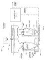
- FIG. 7 illustrates a diagram of an embodiment of a solar-driven bio-refinery
- FIG. 8 illustrates a flow diagram of an embodiment of the system.
- the solar-driven bio-refinery includes an entrained-flow biomass feed system.
- the system may be feedstock flexible via at least particle size control of the biomass without having to change the components making up the feed system.
- One example system includes a chemical reactor, one or more a feeding vessels, and an on-site fuel synthesis reactor.
- the chemical reactor may receive concentrated solar thermal energy from an array of heliostats and this energy can be used to refine the biomass.
- a heliostat is generally a device that tracks the movement of the sun and typically utilizes a mirror to redirect sunlight toward a stationary target or receiver such as a solar thermal tower.
- Some embodiments relate to the entrained-flow biomass feed system that uses an entrainment carrier gas and supplies a variety of biomass sources fed as particles into the solar-driven chemical reactor.
- the variety of biomass sources may include three or more types of biomass that can be fed, individually or in combinational mixtures. These sources can include rice straw, rice hulls, corn stover, switch grass, non-food wheat straw, miscanthus, orchard wastes, forestry wastes, sorghum, source separated green wastes and other similar biomass sources. Additionally, the biomass sources may be used in a raw state or partially torrefied state as long as a few parameters are controlled such as the particle size.
- a feeding vessel such as a lock hopper, in the biomass feed system supplies a tube subset of two or more reactor tubes in the solar-driven chemical reactor.
- concentrated solar thermal energy drives gasification of the particles of the biomass to generate at least hydrogen and carbon monoxide products from the gasification reaction.
- FIG. 1 illustrates a block diagram of an embodiment of an example process flow.
- Some embodiments encompass a solar-driven-biomass gasification to liquid fuel/electrical process.
- the process might also include generation, chemical processing, or bio-char, for solar generated syngas derivative product or other similar technical process.
- the process described is a solar-driven-biomass gasification to ‘green’ liquid fuel process.
- this process includes one or more of the following process steps.
- Biomass grinding or densification, transport, and then offload 100 may be part of the overall process.
- Bales of the biomass can be compressed and densified by a compactor to facilitate transport to on-site via the densification achieved by the compression and the bales are sized to dimensions that may, for example, fit within a standard box car size or shipping container size to fit within standard compactor size.
- the entrained-flow biomass feed system can be preceded by a grinding system equipped with mechanical cutting device and a particle classifier, such as a perforated screen or a cyclone, to control the size of the particles that are then fed into and gasified in the solar-driven chemical reactor.
- Equipment generally used for grinding biomass includes impact mills (e.g. hammer mills), attrition mills, and kinetic disintegration mills-KDS (e.g. flail mills).
- a hammer mill system, KDS, or similar system can be used to grind the bales (loaded by conveyer) into particles, which are to be fed into the solar thermal gasifier.
- the ground particles have an average screen size between 500 microns (um) and 1000 um in diameter, and are loaded into, a silo with a standard belt conveyer or with a positive or negative pressure pneumatic conveying system.
- the ground particles may also have an average screen size between 50 microns (um) and 1000 um, 50 microns (um) and 200 um, 50 microns (um) and 2000 um and various combinations.
- the biomass may then be stored 102 .
- the biomass will be fed 104 into an example solar-driven chemical reactor via a feed system.
- a lock-hopper feed system feeds the particles of biomass into the solar-driven chemical reactor to be gasified.
- the feed system can supply the variety and types of biomass particles discussed above.
- a solar receiver and gasifier 106 may be used to thermally decompose the biomass.
- An example biomass gasifier design and operation can include a solar chemical reactor and solar receiver to generate components of syngas.
- Various heliostat field designs and operations to drive the biomass gasifier might be used.
- Some example designs may include a solar concentrator, secondary concentrator, focused mirror array, etc. to drive biomass gasifier 110 .
- Quenching, gas clean up, and ash removal from biomass gasifier 108 may be provided for. Some non-pilot syngas may exit the system 112 . Some gasses may be a waste product, while other gasses can be compressed 114 prior to storage 118 or e.g., methanol synthesis 116 . Methanol may then be stored 120 for later methanol to gasoline conversion 122 .
- synthesis gas may be feed to another technical application.
- Examples include a syngas to other chemical conversion process.
- the other chemical of chemicals produced can include liquefied fuels such as transportation liquefied fuels.
- Some transportation liquefied fuels include jet fuel, DME, gasoline, diesel, and mixed alcohol, bio-char with a high sequestered amount of carbon; chemical production, electricity generation, synthetic natural gas production, heating oil generation, and other similar syngas based technical applications.
- hydrocarbon based fuel, e.g., methanol, 116 may be formed from syngas.
- the methanol may be further converted to gasoline or other fuels 122 and various products may be separated out from the gasoline 124 or syngas. These products, e.g., gasoline, may then be stored for later use as an energy source.
- the solar-driven biorefinery may have a throughput of no less than one dry ton per day of cellulosic biomass from a region with abundant sources, such as California, that will produce “green” gasoline.
- Solar thermal energy may be used to drive gasification of biomass, upgrading the heating value of the feedstock with a renewable energy source, while allowing operation at temperatures where tar formation is negligible.
- Feedstock carbon yield to “green” gasoline is estimated to be at least 30% higher in comparison to conventional thermochemical partial gasification processes since none of the biomass is oxidized for heating value.
- Synthesis gas will be processed using proven catalytic processes into intermediate methanol, and then subsequently into gasoline via the MTG process.
- the product gas will be catalytically converted into a liquid fuel such as transportation diesel or aviation fuels via GTL Fischer-Tropsch process.
- the biorefinery may be built in an area having ample solar irradiation and proximity to a variety of biomass feed stocks.
- an on-site fuel synthesis reactor has an input to receive the hydrogen and carbon monoxide products from the gasification reaction and configured to use the hydrogen and carbon monoxide products in a hydrocarbon fuel synthesis process to create a liquid hydrocarbon fuel.
- synthesis gas may be processed using many different technical applications as discussed above.
- the solar generated syngas can be used with proven catalytic processes into intermediate methanol, and then subsequently into gasoline via the MTG process.
- the biorefinery will be the first solar unit integrated with a downstream liquid transportation fuels plant.
- the fuel synthesis reactor may be geographically located on the same site as the chemical reactor and integrated into the process to utilize the hydrogen and carbon monoxide products from the gasification reaction.
- the entrained-flow biomass feed system 104 includes a computerized control system configured to balance the amount of biomass particles flowing in each of the reactor tubes to an amount of solar energy available.
- a 2-phase control system receives a signal from the computerized control system to control flow in the individual reactor tubes by controlling a rotational rate of a screw of a lock hopper feeding the biomass, a rotational rate of airlock type metering device, changing an amount of reactor tubes participating in the gasification reaction, controlling an amount of output/ports supplying biomass, an amount of compression of a flexible pipe section applied to each individual feed line that the biomass particles are flowing through, and other example combinations.
- these biomass feedstock resources can include energy crops such as miscanthus and switchgrass, which are high-impact and high-yield energy crops.
- a biomass with low lignin content will make it easier to gasify and process in the solar gasifier.
- Moving the biomass from the field into the reaction zone of the solar gasifier can include a number of steps, such as biomass densification, biomass transport, biomass offload, and biomass storage.
- the biomass such as rice straw, corn stover, high biomass sorghum, switchgrass, miscanthus, bales can be compressed to make transportation via the densification more economical. Compression allows very high loadings on the train cars and trucks.
- Transport biomass to site 100 occurs 1) with the biomass aggregated in the field as bales, 2) the bales are then compressed, and 3) these bales are loaded into shipping containers for transport.
- torrefaction of the biomass may be implemented to densify energy content per unit weight of biomass hence reduce the effective shipping cost. Physical location in U.S. may play a large part in what feedstock we use due to shipping and availability issues.
- the bales are loaded into standard shipping containers by forklift and transported by rail to the site.
- the densification achieved by compression allows high loadings on the train cars and/or trucks, greatly reducing transportation costs. This allows lower cost transportation of biomass from highly fertile regions to the arid desert regions where the solar facilities will be located.
- the biomass materials are offloaded at the plant site, ground in a hammer mill, and fed across a pressure barrier into the entrained flow reactor.
- the biomass is unloaded and stored in a covered shed.
- the biomass storage is at the base of the solar tower for best accessibility to the grinding and the feeding systems.
- spoilage only occurs in 1%-3% of delivered straw and grass feed stocks. Spoilage will be tested in a delivery burn test at the primary grinding site, with rejection of spoiled biomass occurring before grinding.
- FIG. 2 illustrates a diagram of an example multiple tube chemical reactor 200 that may be used in a solar-driven system.
- Reactor 200 has multiple reactor tubes 202 , 204 , 206 , 208 and a separate entrainment line may be used for each of the gasifier reactor tubes 202 , 204 , 206 , 208 in the chemical reactor 200 . This may allow for independent temperature control and balancing of the amount of particles of biomass flowing in each of the gasifier reactor tubes 202 , 204 , 206 , 208 in the multiple-tube solar-driven chemical reactor 200 .
- An example lock hopper rotary feed system has an output to distribute the particles of biomass to the gasifier reactor tubes 202 , 204 , 206 , 208 .
- the rotary feed system such as a Rotoscrew® in combination with a fluid bed splitter can allow for balanced feeding to individual reactor tubes 202 , 204 , 206 , 208 .
- An additional auger may be mounted in the lock hopper to aid the flow of the biomass into the Rotoscrew®.
- the feed rate of the biomass particles is controlled by a weight measuring metering device, such as load cells, and by the rotational speed of the Rotoscrew® set by a device such as variable frequency drive (VFD).
- VFD variable frequency drive
- the Rotoscrew® may be located at the base of the lock hopper and its rotational speed can be controlled by a computerized control system to respond to feed demand of the system.
- the control system may operate in a networked environment using logical connections to one or more remote computers, such as a remote computer.
- the control system hardware may be one or more of a Programmable Logic Controller, via different data communication protocols using Personal Computer, Macintosh, CNC, neural nets, analog devices, with accompanying software applications and algorithms scripted to perform various functions, or various combinations of these systems.
- the computerized control system controls the feed rate of biomass particles in the solar-driven chemical reactor based on an amount of solar energy available indicated by sensors including temperature sensors and/or light meters, temperature of the reactor tubes indicated by one or more temperature sensors, particle size and type of biomass being used, and other parameters supplied to the computerized control system such as product yield and composition.
- the solar-driven bio-refinery can include a solar-driven chemical reactor that has a cyclic operation rather than a continuous steady state operation.
- One or more sensors indicate an amount of solar energy available during the cyclic operations.
- the computerized control system receives a feedback signal from a set of sensors, including the solar energy sensors.
- the computerized control system controls the feed rate of the particles of biomass material into the two or more reactor tubes with well controlled feed rates that respond to changing of the feed rate of the biomass material based on changing solar availability given as feedback to the computerized control system by the solar energy sensors.
- FIG. 3 illustrates a diagram of an example solar tower 300 with receivers 302 and heliostat field 304 .
- solar tower 300 may be used to from a solar-driven bio-refinery with the entrained-flow biomass feed system.
- the feed system can be feedstock flexible via, for example, particle size control of the biomass.
- a solar tower 300 may form a portion of a solar-driven bio-refinery that may also include a biomass feed system that has balancing of the feed lines to each of the reactor tubes in a multiple tube chemical reactor.
- biomass may be fed to the solar reactor in an operation including three parts: biomass transport and preparation for feeding to the solar tower reactor, biomass transport to the top of the, e.g., 500+ foot tower, and distribution into the specific downdraft tubes of the reactor. The distribution may be performed via multiple stages.
- the system uses an entrainment gas to convey particles from the ground into the tubes.
- that entrainment gas which may be hydrocarbon gas, such as Low Pressure Gas (LPG), natural gas, methane, etc., H 2 O steam produced with energy recovered from waste heat in the plant, or CO 2 recycled from the amine unit, may be used as the purging gas in the lock hopper.
- the pressurization can be provided by for example, recycled carbon dioxide from the amine acid gas removal step or dry steam heated by waste heat from products coming out of the chemical reactor.
- the biomass may be pressurized up to 75 psig (15-75 psig range), for example. The pressurized biomass may then be entrained in the steam or other carrier gas, and fed up the tower to the solar thermal gasifier.
- the particles of biomass are pre-heated prior to entry into the chemical reactor by the entrainment carrier gas.
- the entrainment carrier gas is at least one of carbon dioxide gas and steam, which is heated by waste heat from the reaction products of the gasification reaction coming out of the chemical reactor by a counter flow heat exchanger using the waste heat as its heat source to heat the entrainment carrier gas up to a maximum temperature of 300 degrees C.
- the entrained-flow biomass feed system can include a computerized control system configured to balance the amount of biomass particles flowing in each of the reactor tubes to an amount of solar energy available via, for example, a 2-phase control system to control flow in the individual reactor tubes.
- One or more detectors may indicate to the computerized control system an amount of solar energy available in different areas of the chemical reactor to guide a distribution of the biomass particles flowing in each of the reactor tubes.
- the feed can be distributed evenly among the tubes within subsets of tubes and the biomass supply to the solar receiver can be controlled by engaging different numbers of tube subsets.
- the control system balances the amount of biomass particles flowing into each of the reactor tubes to an amount of solar energy available by 1) controlling a rotational rate of a screw of a lock hopper feeding the biomass where all the tubes in the tube subset have their feed rate simultaneously turned up or turned down, 2) where of the multiple reactor tubes is split into two or more groups of tube subsets and varying an amount of the reactor tube-subsets participating in the gasification reaction by turning on or turning off a flow of particles of biomass from the feed vessel to the reactor tubes making up a tube subset, or 3) a combination of both.
- onsite biomass storage can have bales stored at the base of the solar tower for best accessibility to the feeding and grinding systems.
- Biomass bales are stored in a silo type structure with bale moisture content between 5-50% with a typical range between 10% and 14%.
- the biomass, such as rice straw, rice hulls, corn stover, etc. bales can be stored onsite in a Biomass Storage unit located at the base of the solar tower for best accessibility to the feeding system.
- the gasification of the biomass occurs in two phases.
- An important aspect of the initial phase of gasification is that it is relatively fast at low temperatures and extremely fast at high temperatures, with completion in 0.1-0.3 seconds at least 600° C.
- this primary phase can be completed quickly in the aerosol reactor, and the remaining char and tars can heat up to temperatures of at least 950° C. where their gasification can be completed.
- the char gasification phase is the slowest reaction step of the solar biomass gasification process but is possible with short residence times at these temperatures.
- FIG. 4 illustrates cumulative particle size distributions.
- the graph illustrates the weight percentage below Y % for a given screen size in microns.
- Four example materials are illustrated with the corresponding milling power requirements: knife-chopped rice straw at 48 kilowatt-hours per ton in a hammer-mill, knife-chopped rice straw with an unknown energy value per ton in KDS, miscanthus stems at 35 kilowatt-hours per ton in a hammer-mill, and pelletized rice straw at 190 kilowatt-hours per ton including energy for both pelletization and grinding.
- the grinding system and the feed system may supply the various biomass types.
- Biomass particle size is a parameter that can impact performance of this solar-driven gasifier reactor. Through the mass transfer coefficient and residence time, biomass particle size controls intrinsic biomass reactivity and imposes specific solids handling constraints. In general, there is a trade-off between particle size range required by gasification kinetics, and the capital and operating costs associated with providing target biomass size reduction. In addition, the final material properties affect transportation cost (bulk density) as well as the cost of conveyers, bins, hoppers, and required energy for high pressure pneumatic transport. Based on the kinetic experiments described herein, the particle size required for the process may be generally between 50 um and 2000 um, for example.
- the entrained-flow biomass feed system can include a gas source for an entrainment carrier gas and one or more feed lines to supply a variety of biomass sources that may be fed as particles into the solar-driven chemical reactor.
- the variety of biomass sources feedable by the feed system without major configuration changes includes the below described three or more of the types of biomass.
- biomass sources may include rice straw, rice hulls, corn stover, switch grass, non-food wheat straw, miscanthus, orchard wastes, forestry wastes, source separated green wastes and other similar biomass sources. These biomass sources may be in a raw state or partially (torrefied) state, as long as a few parameters such as particle size are controlled. Concentrated solar thermal energy can drive the gasification of the particles of the biomass in the solar-driven chemical reactor to generate hydrogen, carbon monoxide, and perhaps other gases from the gasification reaction.
- the biomass may be fed into an example solar gasification system using an entrained-flow biomass feed system that includes a computerized control system.
- a computerized control system can control the biomass flow rate for the particle size, type of biomass, and current estimated temperature in each reactor tube.
- the temperature may be selected to achieve from the gasification reaction a greater than 90 percent conversion of the biomass particles to at least hydrogen and carbon monoxide products with low to zero tar of less than 50 mg/Nm ⁇ 3.
- the tar content may be less than 200 mg/Nm ⁇ 3.
- the solar gasification process can be feedstock flexible and may be able to leverage a wide variety of biomass types.
- the reactor will be feedstock flexible as long as the particle size is controlled.
- the feed system is less sensitive to the type of feedstock used.
- types of biomass can be selected based on parameters of the amount of moles of H 2 , CO, and CO 2 gas produced from the gasification per ton, different ash content, and availability in quantity to be a renewable source of biomass to support consumption demands of transportation industry.
- FIG. 5 illustrates a diagram of a solar thermal receiver 500 with gasifier reactor tubes 502 .
- the solar thermal receiver 500 can form a portion of a solar-driven bio-refinery.
- the solar thermal receiver 500 can be a solar-driven chemical reactor that has multiple reaction tubes in a downdraft orientation.
- the feed system may feed biomass particles into the multiple reaction tubes 502 , in which the particles of biomass may be gasified in the presence of steam in a gasification reaction zone at a temperature exceeding 950 degrees C. from the exit of the gasification reaction zone of the reactor tubes. At least hydrogen and carbon monoxide products are generated from the gasification reaction.
- the entrained-flow biomass feed system may include a device such as a BulkmatologyTM Pelletron Flow EnhancerTM, which may control an amount of entrainment gas carrying the particles of biomass to a gasification reaction zone of the reactor tubes by leaking out a portion of the carrier gas just prior to an entrance to a gasification reaction zone of the reactor tubes, thereby increasing the biomass-to-carrier gas weight ratio at the entrance to the reactor tubes.
- a device such as a BulkmatologyTM Pelletron Flow EnhancerTM, which may control an amount of entrainment gas carrying the particles of biomass to a gasification reaction zone of the reactor tubes by leaking out a portion of the carrier gas just prior to an entrance to a gasification reaction zone of the reactor tubes, thereby increasing the biomass-to-carrier gas weight ratio at the entrance to the reactor tubes.
- the entrained solids of biomass-to-carrier gas ratio at the entrance of the reactor tubes may be as much as three times its counterpart in the conveying lines upstream of Pelletron Flow Enhanc
- a reduction in the carrier gas flow rate can occur near the top of the reactor tubes in the downdraft solar thermal receiver allowing unimpeded inertia-driven flow of dispersed particles into the reactor tubes.
- an outlet of each of the feed lines can be configured to control a desired dispersion pattern of the biomass particles into its corresponding reactor tube to maximize radiation absorption by the particles when injected into the reactor tube based on a shape and width of the outlet of the feed line pipe carrying the biomass particles to its corresponding reactor tube.
- FIGS. 6 a and 6 b illustrate block diagrams of embodiments of the entrained-flow biomass feed system 600 .
- Different types of feed systems may be used in conjunction with a biomass reactor, for example, drop tube, total solid feed into the reactor, slurry feed into the reactor, a moveable bed in the reactor, or combinations of these schemes.
- One or more feeding vessels in the biomass feed system supply two or more reactor tubes in the solar-driven chemical reactor.
- Each of the feeding vessels has one or more outlets configured to supply a consistent volumetric amount of biomass particles within 10 percent of the demand signal amount when distributing biomass particles to the two or more reactor tubes.
- the injection rate to each injection point into carrier gas lines is within +/ ⁇ 10% of the desired demand signal amount.
- each of the feeding vessels has one or more outlets configured to supply a consistent volumetric amount of biomass particles within 5 percent of the demand signal amount when distributing biomass particles to the two or more reactor tubes for a tighter controlled system. In an embodiment, each of the feeding vessels has one or more outlets configured to supply a consistent volumetric amount of biomass particles within 20 percent of the demand signal amount when distributing biomass particles to the two or more reactor tubes for a system more tolerant of particle size.
- One example solar-driven bio-refinery may include the entrained-flow biomass feed system 600 that includes or otherwise cooperates with a grinding system.
- the grinding process 603 and feed process may be 1) processes separated in time and completed independently of the other process or 2) a continuous process of the where the grinding process 603 occurs and immediately feeds biomass into the feed system and then into the chemical reactor.
- the feeding vessel may use an Auger/Screw feeder or an airlock-type rotational solids feeding/rate metering device.
- a screw feeder type that controls biomass particle feeding/rate will be discussed and a RotoScrewTM will be given as a common example of this type.
- An airlock-type rotational metering device that controls biomass particle feeding/rate and uses entrainment gas to carry solids along the axis of rotation will be discussed and a RotoFeedTM will be given as a common example of this type.
- An embodiment of the feeding vessel has the injection vessel configured to discharge ground particles of biomass through a multiplicity of single-outlet rotational feed devices, such as the screw feeder type or the airlock type, that provide a consistent volumetric federate, each feeding separate biomass entrainment lines.
- the rotational speed of each of the rotational feed devices is controlled independently.
- Each of the rotational feed devices feeds a separate reactor tube.
- An embodiment of the feeding vessel has the injection vessel configured to discharge ground particles of biomass via a multi-outlet rotational device such as a (RotoFeedTM). All the outlets have the same nominal biomass feed rate controlled by the rpm on the RotoFeedTM.
- a multi-outlet rotational device such as a (RotoFeedTM). All the outlets have the same nominal biomass feed rate controlled by the rpm on the RotoFeedTM.
- the grinding system 603 such as a hammer mill system, KDS, etc. may have a conveyer bringing biomass potentially in bales, which are debaled via a bale cutter/debaler, and then grinds the de-baled biomass into particles via a mechanical cutting device cooperating with a set of filters with specific sized holes in the filters.
- the grinding system 603 generates particles that have an average smallest dimension size between 200 um and 2000 um, such to fit through the holes in the filters, with a general range of between 500 um and 1000 um.
- the primary particles are then loaded into a lock hopper system 601 with a standard belt or pneumatic conveyer.
- the lock hopper system may have one or more injection vessels.
- the lock hopper 604 has one or more output ports to then feed the biomass particles across a pressure boundary into the pressurized entrainment carrier gas for feeding one or more feed lines into in the solar-driven chemical reactor.
- the entrained-flow biomass feed system 600 can include a pressurized lock hopper 604 that feeds the biomass to a rotating metering feed screw 602 and then into an entrainment gas pipe at the lock hopper exit 606 .
- the particles of the biomass are distributed into multiple entrainment gas lines by a flow splitter to feed the two or more reactor tubes making up the solar-driven chemical reactor.
- One or more methanol units may be in the on-site fuel synthesis reactor.
- the gas source 610 may supply a hydrocarbon gas, pressurized dry steam, or other gas as the entrainment carrier gas for the entrained-flow biomass feed system.
- the pressurized dry steam can be generated from waste heat recovered from at least one of 1) the hydrocarbon fuel synthesis process in the on-site fuel synthesis units and 2) the reaction products from the gasification reaction coming out of the solar-driven chemical reactor.
- the entrained-flow biomass feed system 600 can include a multi-outlet lock hopper with a number of metering rotating screws to feed each of the separate feed lines.
- the feed rate is controlled by each feed line's metering screw and controlling the rotational rate of the screw at the base of the lock hopper, which responds to a feed demand signal from a computerized control system, and the computerized control system controls a flow rate of particles of biomass in the solar-driven chemical reactor based on an amount of solar energy available indicated by sensors for the chemical reactor including temperature sensors and/or light meters.
- High pressure feeding of solids of biomass with gasification at pressure may reduce capital cost due to the ability to use smaller compressors in the post-gasification MTG or GTL processes. Additionally, operating cost may be reduced because energy for pressurizing carrier gas comes from the sun, as opposed to from electricity.
- the lock hopper system can feed the reactor processes at pressure.
- the feeding system can entrain the biomass materials in steam at high pressure, successfully disengage the particulates in the cyclone system, and distribute flow appropriately to the reactor tubes.
- the high-pressure entrainment gas can be used in the form of natural gas that is supplied at elevated pressure in which case the methane component of the entrainment gas may be reformed with the steam to provide additional amounts of carbon monoxide and hydrogen.
- the methane to biomass feed ratio can be used as means of controlling the quality of the product syngas.
- the computer control system may determine the temperatures, and control the residence times and the amount of particles traveling through the downdraft reactor at a particular time to achieve high conversion, and may lead to almost complete gasification of the biomass, including lignin fractions. Due to intrinsic variability in the available solar energy, the biomass feed rate for a given amount of concentrated solar energy from the concentrating field needs to be controlled by the computer control system to adjust biomass in verses the heat sink effect in the solar receiver and reactor of the biomass in the reactor tubes using the heat of the receiver and reactor to drive the gasification reaction; and thus, a balancing of mass in to supplied energy occurs to keep the target set point reactor tube temperature in a controlled temperature range.
- the computer control system may use computational models incorporating full mass and energy balances to predict the temperature history of the flowing particles and solar energy distribution within the receiver cavity for reaction rate.
- the biomass particles can be fed to a multi-tube downdraft solar thermal receiver/reactor, in which the biomass is gasified in the presence of steam at temperatures exceeding 950-1000° C.
- the biomass can be gasified at 1000° C., 1150° C., 1200° C., and 1300° C. with residence times ranged between 0.01 s and 5.0 s.
- the heat from the gasification reaction products can be put to useful work.
- the system can also use a counter flow heat exchange to heat the carrier gas up to a temperature below 300° C. and keeping the temperature below 300° C.
- the system may recuperate waste heat from other process areas, which can decrease the amount of concentrated light needed to rapidly heat the biomass to a tar free temperature zone and the need for a secondary concentrator.
- FIG. 7 illustrates a diagram of an embodiment of a solar-driven bio-refinery 800 .
- solar power 802 may be provided through a window or aperture 804 to a solar heated reactor chamber 806 .
- a quencher 808 may be used to prevent back reaction.
- biomass particles flow into the system at 810 and syngas flows out 812 . Additionally, a heat exchange may occur between the biomass particles and the syngas.
- an on-site fuel synthesis reactor 808 may receive the hydrogen and carbon monoxide products from the gasification reaction and use the hydrogen and carbon monoxide products in a hydrocarbon fuel synthesis process to create a liquid hydrocarbon fuel.
- the fuel synthesis reactor 806 may be geographically located on the same site as the chemical reactor and integrated into the process to utilize the hydrogen and carbon monoxide products from the gasification reaction.
- a 2-phase control system can also include a pinch valve system on each feed line to each reactor tube that receives dynamic feedback from the computerized control system to control an amount of compression of a flexible pipe section of the feed line that the biomass particles are flowing through.
- the entrained-flow biomass feed system can use an entrainment carrier gas and supplies biomass as particles into each of the reactor tubes of the solar-driven chemical reactor.
- a separate entrainment line and metering device of the entrained-flow biomass feed system is used for each of the gasifier reactor tubes in the chemical reactor. This can allow balancing of 1) an amount of the particles of non-food biomass flowing to each reactor tube to 2) a temperature of that reactor tube in the multiple tube solar-driven chemical reactor.
- the concentrated solar thermal energy drives gasification of the biomass at an exit temperature that may exceed 950 degrees ° C. to achieve a greater than 90% conversion of biomass particles to at least hydrogen and carbon monoxide products with low to zero tar production from the gasification reaction in some embodiments.
- the entrained-flow biomass feed system supplies a variety of three or more types of biomass that can be fed, individually or in combinational mixtures of biomass sources fed as particles into the solar-driven chemical reactor as long as a few parameters are controlled, including particle size of the biomass supplied by the feed lines, without having to change the components making up the feed system.
- a solar-driven bio-refinery allows for feedstock flexibility in the type of biomass making up the particles of biomass because the design also obviates any need for an exothermic/endothermic reaction balancing in the chemical reactor.
- the concentrated solar energy drives the endothermic gasification reaction and thereby the biomass need not be burned.
- at least two or more different types of biomass materials might be used in the same reactor tube geometry in some example systems. This can obviate any need for a complete reengineering when a new type of biomass feedstock is used. It will be understood that multiple feed stocks could be used simultaneously or one feedstock might be used at a time.
- Some systems may use commercially available grades of fumed silica blended with the biomass to aid in a bulk flow of the biomass materials that otherwise would tend to bridge due to strong Van der Waals inter-particle forces. This assists in the three or more types of biomass that can be fed, individually or in combinational mixtures without having to change the components making up the feed system. Factors causing the presence of these forces include moisture and “sticky” organics (such are resins typically found in woody biomass materials). Some systems may use AerosilTM and SpernatTM from the product line, which is a product of Evonik Industries AG. A mechanical agitator in the lock hopper or feeding vessel can also be used to enhance the bulk flow of biomass particles that might otherwise tend to bridge in the vessel due to Van der Waal's forces.
- biomass feeding occurs.
- high pressure feeding may be used.
- High pressure feeding of solids of biomass with gasification at pressure may reduce capital cost of the downstream liquid fuel plant 906 due to the ability to use smaller compressors in some such systems. Additionally, operating cost may be reduced because energy for pressurizing carrier gas comes from the sun, as opposed to from electricity.
- the lock hopper system can feed the reactor processes at pressure.
- step 904 gasification occurs.
- concentrated solar thermal energy drives gasification of the particles of the biomass to generate at least hydrogen and carbon monoxide products from the gasification reaction.
- this chemical reactor design may have a cyclic operation rather than a continuous steady state operation. This design and its operational strategy are designed with the goal of cyclic operation, such as diurnal operation.
- step 906 fuel synthesis occurs.
- An on-site fuel synthesis reactor can receive the hydrogen and carbon monoxide products from the gasification reaction and use the hydrogen and carbon monoxide products in a hydrocarbon fuel synthesis process to create a liquid hydrocarbon fuel.
- the fuel synthesis reactor may be geographically located on the same site as the chemical reactor and integrated into the process to utilize the hydrogen and carbon monoxide products from the gasification reaction.
- a machine-readable medium to store instructions and data of the software is understood to include any mechanism for storing or transmitting information in a form readable by a machine (e.g., a computer).
- a machine-readable medium includes read only memory (ROM); random access memory (RAM); magnetic disk storage media; optical storage media; flash memory devices, etc.
Abstract
Description
Claims (19)
Priority Applications (4)
| Application Number | Priority Date | Filing Date | Title |
|---|---|---|---|
| US12/796,222 US9150803B2 (en) | 2009-06-09 | 2010-06-08 | Systems and methods for biomass grinding and feeding |
| AU2010258845A AU2010258845B2 (en) | 2009-06-09 | 2010-06-09 | Systems and methods for biomass grinding and feeding |
| PCT/US2010/037923 WO2010144542A1 (en) | 2009-06-09 | 2010-06-09 | Systems and methods for biomass grinding and feeding |
| US14/852,077 US20150376518A1 (en) | 2009-06-09 | 2015-09-11 | Systems and methods for biomass grinding and feeding |
Applications Claiming Priority (3)
| Application Number | Priority Date | Filing Date | Title |
|---|---|---|---|
| US18549209P | 2009-06-09 | 2009-06-09 | |
| US24828209P | 2009-10-02 | 2009-10-02 | |
| US12/796,222 US9150803B2 (en) | 2009-06-09 | 2010-06-08 | Systems and methods for biomass grinding and feeding |
Related Child Applications (1)
| Application Number | Title | Priority Date | Filing Date |
|---|---|---|---|
| US14/852,077 Continuation US20150376518A1 (en) | 2009-06-09 | 2015-09-11 | Systems and methods for biomass grinding and feeding |
Publications (2)
| Publication Number | Publication Date |
|---|---|
| US20100242353A1 US20100242353A1 (en) | 2010-09-30 |
| US9150803B2 true US9150803B2 (en) | 2015-10-06 |
Family
ID=42736707
Family Applications (13)
| Application Number | Title | Priority Date | Filing Date |
|---|---|---|---|
| US12/796,471 Abandoned US20100242354A1 (en) | 2009-06-09 | 2010-06-08 | Systems and methods for reactor chemistry and control |
| US12/795,910 Expired - Fee Related US8821599B2 (en) | 2009-06-09 | 2010-06-08 | Systems and methods for biomass gasifier reactor and receiver configuration |
| US12/796,319 Active 2033-02-12 US8709112B2 (en) | 2009-06-09 | 2010-06-08 | Systems and methods for quenching, gas clean up, and ash removal |
| US12/795,989 Abandoned US20100242352A1 (en) | 2009-06-09 | 2010-06-08 | Systems and methods for reactor and receiver control of flux profile |
| US12/796,222 Expired - Fee Related US9150803B2 (en) | 2009-06-09 | 2010-06-08 | Systems and methods for biomass grinding and feeding |
| US12/795,947 Expired - Fee Related US9150802B2 (en) | 2009-06-09 | 2010-06-08 | Systems and methods for an indirect radiation driven gasifier reactor and receiver configuration |
| US12/796,045 Expired - Fee Related US8771387B2 (en) | 2009-06-09 | 2010-06-08 | Systems and methods for solar-thermal gasification of biomass |
| US12/796,428 Abandoned US20100249251A1 (en) | 2009-06-09 | 2010-06-08 | Systems and methods for cyclic operations in a fuel synthesis process |
| US12/796,121 Active 2031-03-23 US8378151B2 (en) | 2009-06-09 | 2010-06-08 | Systems and methods for an integrated solar driven chemical plant |
| US14/325,701 Abandoned US20140318013A1 (en) | 2009-06-09 | 2014-07-08 | Simultaneous reactions with gasification of biomass |
| US14/852,077 Abandoned US20150376518A1 (en) | 2009-06-09 | 2015-09-11 | Systems and methods for biomass grinding and feeding |
| US14/875,290 Abandoned US20160024403A1 (en) | 2009-06-09 | 2015-10-05 | Systems and methods for an indirect radiation driven gasifier reactor and receiver configuration |
| US15/419,826 Abandoned US20170137284A1 (en) | 2009-06-09 | 2017-01-30 | Various methods and apparatuses for multi-stage synthesis gas generation |
Family Applications Before (4)
| Application Number | Title | Priority Date | Filing Date |
|---|---|---|---|
| US12/796,471 Abandoned US20100242354A1 (en) | 2009-06-09 | 2010-06-08 | Systems and methods for reactor chemistry and control |
| US12/795,910 Expired - Fee Related US8821599B2 (en) | 2009-06-09 | 2010-06-08 | Systems and methods for biomass gasifier reactor and receiver configuration |
| US12/796,319 Active 2033-02-12 US8709112B2 (en) | 2009-06-09 | 2010-06-08 | Systems and methods for quenching, gas clean up, and ash removal |
| US12/795,989 Abandoned US20100242352A1 (en) | 2009-06-09 | 2010-06-08 | Systems and methods for reactor and receiver control of flux profile |
Family Applications After (8)
| Application Number | Title | Priority Date | Filing Date |
|---|---|---|---|
| US12/795,947 Expired - Fee Related US9150802B2 (en) | 2009-06-09 | 2010-06-08 | Systems and methods for an indirect radiation driven gasifier reactor and receiver configuration |
| US12/796,045 Expired - Fee Related US8771387B2 (en) | 2009-06-09 | 2010-06-08 | Systems and methods for solar-thermal gasification of biomass |
| US12/796,428 Abandoned US20100249251A1 (en) | 2009-06-09 | 2010-06-08 | Systems and methods for cyclic operations in a fuel synthesis process |
| US12/796,121 Active 2031-03-23 US8378151B2 (en) | 2009-06-09 | 2010-06-08 | Systems and methods for an integrated solar driven chemical plant |
| US14/325,701 Abandoned US20140318013A1 (en) | 2009-06-09 | 2014-07-08 | Simultaneous reactions with gasification of biomass |
| US14/852,077 Abandoned US20150376518A1 (en) | 2009-06-09 | 2015-09-11 | Systems and methods for biomass grinding and feeding |
| US14/875,290 Abandoned US20160024403A1 (en) | 2009-06-09 | 2015-10-05 | Systems and methods for an indirect radiation driven gasifier reactor and receiver configuration |
| US15/419,826 Abandoned US20170137284A1 (en) | 2009-06-09 | 2017-01-30 | Various methods and apparatuses for multi-stage synthesis gas generation |
Country Status (4)
| Country | Link |
|---|---|
| US (13) | US20100242354A1 (en) |
| CN (4) | CN102459528A (en) |
| AU (7) | AU2010258840B2 (en) |
| WO (9) | WO2010144540A1 (en) |
Cited By (2)
| Publication number | Priority date | Publication date | Assignee | Title |
|---|---|---|---|---|
| US10047307B2 (en) | 2013-03-15 | 2018-08-14 | All Power Labs, Inc. | Hybrid fixed-kinetic bed gasifier for fuel flexible gasification |
| US10351777B2 (en) | 2013-03-15 | 2019-07-16 | All Power Labs, Inc. | Simultaneous pyrolysis and communition for fuel flexible gasification and pyrolysis |
Families Citing this family (179)
| Publication number | Priority date | Publication date | Assignee | Title |
|---|---|---|---|---|
| US20150121869A1 (en) * | 2004-11-09 | 2015-05-07 | Mcalister Technologies, Llc | Sustainable economic development through integrated production of renewable energy, materials resources, and nutrient regimes |
| US8318131B2 (en) | 2008-01-07 | 2012-11-27 | Mcalister Technologies, Llc | Chemical processes and reactors for efficiently producing hydrogen fuels and structural materials, and associated systems and methods |
| US9188086B2 (en) | 2008-01-07 | 2015-11-17 | Mcalister Technologies, Llc | Coupled thermochemical reactors and engines, and associated systems and methods |
| JP5730775B2 (en) | 2008-11-26 | 2015-06-10 | エレバンス リニューアブル サイエンシズ, インク.Elevance Renewable Sciences,Inc. | Method for producing jet fuel from natural oil feedstock via metathesis reaction |
| CN102227489B (en) | 2008-11-26 | 2015-04-15 | 埃莱文斯可更新科学公司 | Methods of producing jet fuel from natural oil feedstocks through oxygen-cleaved reactions |
| US9909067B2 (en) | 2009-01-21 | 2018-03-06 | Cool Planet Energy Systems, Inc. | Staged biomass fractionator |
| US8441361B2 (en) | 2010-02-13 | 2013-05-14 | Mcallister Technologies, Llc | Methods and apparatuses for detection of properties of fluid conveyance systems |
| CN101758572A (en) * | 2009-03-30 | 2010-06-30 | 楼正荣 | Integrative multiple-chamber grading plastic oven charging basket |
| US9663363B2 (en) | 2009-06-09 | 2017-05-30 | Sundrop Fuels, Inc. | Various methods and apparatuses for multi-stage synthesis gas generation |
| US20100242354A1 (en) * | 2009-06-09 | 2010-09-30 | Sundrop Fuels, Inc. | Systems and methods for reactor chemistry and control |
| US9011560B2 (en) | 2009-06-09 | 2015-04-21 | Sundrop Fuels, Inc. | Various methods and apparatuses for an ultra-high heat flux chemical reactor |
| US8814961B2 (en) | 2009-06-09 | 2014-08-26 | Sundrop Fuels, Inc. | Various methods and apparatuses for a radiant-heat driven chemical reactor |
| US9051519B2 (en) | 2009-10-12 | 2015-06-09 | Elevance Renewable Sciences, Inc. | Diene-selective hydrogenation of metathesis derived olefins and unsaturated esters |
| US9169447B2 (en) | 2009-10-12 | 2015-10-27 | Elevance Renewable Sciences, Inc. | Methods of refining natural oils, and methods of producing fuel compositions |
| AU2010307021B2 (en) | 2009-10-12 | 2016-02-18 | Wilmar Trading Pte Ltd | Methods of refining and producing fuel from natural oil feedstocks |
| US9000246B2 (en) | 2009-10-12 | 2015-04-07 | Elevance Renewable Sciences, Inc. | Methods of refining and producing dibasic esters and acids from natural oil feedstocks |
| US9175231B2 (en) | 2009-10-12 | 2015-11-03 | Elevance Renewable Sciences, Inc. | Methods of refining natural oils and methods of producing fuel compositions |
| US9222056B2 (en) | 2009-10-12 | 2015-12-29 | Elevance Renewable Sciences, Inc. | Methods of refining natural oils, and methods of producing fuel compositions |
| US9382502B2 (en) | 2009-10-12 | 2016-07-05 | Elevance Renewable Sciences, Inc. | Methods of refining and producing isomerized fatty acid esters and fatty acids from natural oil feedstocks |
| US8735640B2 (en) | 2009-10-12 | 2014-05-27 | Elevance Renewable Sciences, Inc. | Methods of refining and producing fuel and specialty chemicals from natural oil feedstocks |
| US9365487B2 (en) | 2009-10-12 | 2016-06-14 | Elevance Renewable Sciences, Inc. | Methods of refining and producing dibasic esters and acids from natural oil feedstocks |
| PL2526044T3 (en) * | 2010-01-19 | 2019-05-31 | Topsoe Haldor As | Process for reforming hydrocarbons |
| AU2011216244A1 (en) | 2010-02-13 | 2012-09-06 | Mcalister Technologies, Llc | Reactor vessels with transmissive surfaces for producing hydrogen-based fuels and structural elements, and associated systems and methods |
| WO2011146847A2 (en) * | 2010-05-20 | 2011-11-24 | Kansas State University Research Foundation | Char-supported catalysts for syngas cleanup and conditioning |
| CN101906324B (en) * | 2010-07-20 | 2013-04-03 | 武汉凯迪控股投资有限公司 | Indirect gasification process of biomass water vapor and equipment thereof |
| JP5535818B2 (en) * | 2010-08-09 | 2014-07-02 | 三菱重工業株式会社 | Biomass gasification gas purification system and method, methanol production system and method |
| JP5501895B2 (en) | 2010-08-09 | 2014-05-28 | 三菱重工業株式会社 | Biomass gasification gas purification system and method, methanol production system and method |
| US8246788B2 (en) | 2010-10-08 | 2012-08-21 | Teal Sales Incorporated | Biomass torrefaction system and method |
| US9017435B2 (en) * | 2010-10-08 | 2015-04-28 | General Electric Company | Gasifier monitor and control system |
| FR2966567B1 (en) * | 2010-10-20 | 2014-11-14 | Centre Nat Rech Scient | COLLECTOR SOLAR ENERGY DEVICE |
| US9069103B2 (en) * | 2010-12-17 | 2015-06-30 | Microsoft Technology Licensing, Llc | Localized weather prediction through utilization of cameras |
| US8849584B2 (en) | 2010-12-29 | 2014-09-30 | Sunedison, Inc. | Systems and methods for particle size determination and control in a fluidized bed reactor for use with thermally decomposable silicon-containing gas |
| US8452547B2 (en) | 2010-12-29 | 2013-05-28 | Memc Electronic Materials, Inc. | Systems and methods for particle size determination and control in a fluidized bed reactor |
| RU2018104472A (en) * | 2011-03-18 | 2019-02-22 | Джензим Корпорейшн | Glucosylceramide synthase inhibitors |
| FR2973483B1 (en) * | 2011-04-04 | 2013-04-26 | Centre Nat Rech Scient | SOLAR SYSTEM FOR REPRODUCING THE EFFECT OF A COMBUSTION FLAME |
| US9926507B2 (en) * | 2011-05-18 | 2018-03-27 | Bioendev Ab | Method for monitoring and control of torrefaction temperature |
| TR201905563T4 (en) | 2011-06-23 | 2019-05-21 | Stamicarbon B V Acting Under The Name Of Mt Innovation Center | Process for producing a synthesis gas vehicle suitable for hydrogen production. |
| KR20140054021A (en) | 2011-07-08 | 2014-05-08 | 유니버시티 오브 플로리다 리서치 파운데이션, 아이엔씨. | Porous stabilized beds, methods of manufacture thereof and articles comprising the same |
| US9950305B2 (en) | 2011-07-26 | 2018-04-24 | Battelle Memorial Institute | Solar thermochemical processing system and method |
| MX350102B (en) * | 2011-07-29 | 2017-08-25 | The Babcock & Wilcox Company * | Shop assembled vertical serpentine flow molten salt solar receiver. |
| EP2742207A4 (en) | 2011-08-12 | 2016-06-29 | Mcalister Technologies Llc | Systems and methods for extracting and processing gases from submerged sources |
| WO2013025659A1 (en) | 2011-08-12 | 2013-02-21 | Mcalister Technologies, Llc | Reducing and/or harvesting drag energy from transport vehicles, includings for chemical reactors, and associated systems and methods |
| US8911703B2 (en) | 2011-08-12 | 2014-12-16 | Mcalister Technologies, Llc | Reducing and/or harvesting drag energy from transport vehicles, including for chemical reactors, and associated systems and methods |
| US8734546B2 (en) | 2011-08-12 | 2014-05-27 | Mcalister Technologies, Llc | Geothermal energization of a non-combustion chemical reactor and associated systems and methods |
| WO2013025650A1 (en) | 2011-08-12 | 2013-02-21 | Mcalister Technologies, Llc | Mobile transport platforms for producing hydrogen and structural materials and associated systems and methods |
| US8821602B2 (en) | 2011-08-12 | 2014-09-02 | Mcalister Technologies, Llc | Systems and methods for providing supplemental aqueous thermal energy |
| US8826657B2 (en) | 2011-08-12 | 2014-09-09 | Mcallister Technologies, Llc | Systems and methods for providing supplemental aqueous thermal energy |
| NL1039007C2 (en) * | 2011-08-26 | 2013-02-27 | Klaas Gerrit Smit | A process and a reaction apparatus for the gasification of wet biomass. |
| PT105874A (en) * | 2011-09-02 | 2013-03-04 | Iberfer Equipamentos E Construcoes Tecn S A | CONVERSION PROCESS OF BIOMASS THERMAL ENERGY IN ELECTRICAL ENERGY AND INSTALLATION OF PRODUCTION OF ELECTRIC ENERGY FOR THE PERFORMANCE OF THE REFERENCE PROCESS |
| US9732986B2 (en) * | 2011-09-21 | 2017-08-15 | King Saud University | Solid particle receiver with porous structure for flow regulation and enhancement of heat transfer |
| AU2012315914B2 (en) * | 2011-09-27 | 2015-07-09 | Thermochem Recovery International, Inc. | System and method for syngas clean-up |
| SG11201401135XA (en) | 2011-10-07 | 2014-10-30 | Pall Technology Uk Ltd | Fluid processing control system and related methods |
| SG11201402566TA (en) | 2011-11-22 | 2014-10-30 | Cool Planet Energy Systems Inc | System and process for biomass conversion to renewable fuels with byproducts recycled to gasifier |
| US9169174B2 (en) | 2011-12-22 | 2015-10-27 | Elevance Renewable Sciences, Inc. | Methods for suppressing isomerization of olefin metathesis products |
| US9139493B2 (en) | 2011-12-22 | 2015-09-22 | Elevance Renewable Sciences, Inc. | Methods for suppressing isomerization of olefin metathesis products |
| US9133416B2 (en) | 2011-12-22 | 2015-09-15 | Elevance Renewable Sciences, Inc. | Methods for suppressing isomerization of olefin metathesis products |
| US9669379B2 (en) * | 2011-12-22 | 2017-06-06 | University Of Florida Research Foundation, Inc | Solar thermochemical reactor, methods of manufacture and use thereof and thermogravimeter |
| US10239036B2 (en) | 2011-12-22 | 2019-03-26 | University Of Florida Research Foundation | Solar thermochemical reactor, methods of manufacture and use thereof and thermogravimeter |
| US9222612B2 (en) | 2012-01-06 | 2015-12-29 | Vadxx Energy LLC | Anti-fouling apparatus for cleaning deposits in pipes and pipe joints |
| US8893505B2 (en) | 2012-02-08 | 2014-11-25 | King Fahd University Of Petroleum And Minerals | Integrated solar-gas turbine cogeneration plant |
| CN105018127A (en) * | 2012-02-09 | 2015-11-04 | 梵德克斯能源有限责任公司 | Apparatus and method for pyrolyzing hydrocarbonaceous materials |
| AU2013221354B2 (en) | 2012-02-15 | 2017-06-29 | Vadxx Energy LLC | Dual stage, zone-delineated pyrolysis apparatus |
| US9126173B2 (en) | 2012-03-26 | 2015-09-08 | Sundrop Fuels, Inc. | Pretreatment of biomass using thermo mechanical methods before gasification |
| CA2865968A1 (en) * | 2012-03-26 | 2013-10-24 | Sundrop Fuels, Inc. | Various methods and apparatuses for multi-stage synthesis gas generation |
| US20130247448A1 (en) * | 2012-03-26 | 2013-09-26 | Sundrop Fuels, Inc. | Optimization of torrefaction volatiles for producing liquid fuel from biomass |
| US8961628B2 (en) | 2012-06-22 | 2015-02-24 | Sundrop Fuels, Inc. | Pretreatment of biomass using steam explosion methods |
| US9347690B2 (en) | 2012-04-02 | 2016-05-24 | Alliance For Sustainable Energy, Llc | Methods and systems for concentrated solar power |
| US9222040B2 (en) | 2012-06-07 | 2015-12-29 | General Electric Company | System and method for slurry handling |
| CN104519991A (en) * | 2012-06-22 | 2015-04-15 | 三照普燃料公司 | Pretreating biomass using steam explosion before gasification |
| US9447326B2 (en) | 2012-06-22 | 2016-09-20 | Sundrop Fuels, Inc. | Pretreatment of biomass using steam explosion methods before gasification |
| US9035116B2 (en) * | 2012-08-07 | 2015-05-19 | Kior, Inc. | Biomass feed system including gas assist |
| WO2014043552A1 (en) * | 2012-09-14 | 2014-03-20 | Sundrop Fuels, Inc. | Improving renewable carbon content in methanol and other products from gasification of biomass |
| US9388098B2 (en) | 2012-10-09 | 2016-07-12 | Elevance Renewable Sciences, Inc. | Methods of making high-weight esters, acids, and derivatives thereof |
| CN104884874A (en) * | 2012-10-16 | 2015-09-02 | 阿文戈亚太阳能有限责任公司 | Coupled chemical-thermal solar power system and method |
| EP2728022A1 (en) * | 2012-11-05 | 2014-05-07 | ETH Zurich | Methods and systems for reducing metal oxides |
| US9175235B2 (en) | 2012-11-15 | 2015-11-03 | University Of Georgia Research Foundation, Inc. | Torrefaction reduction of coke formation on catalysts used in esterification and cracking of biofuels from pyrolysed lignocellulosic feedstocks |
| FR2998355A1 (en) * | 2012-11-20 | 2014-05-23 | Commissariat Energie Atomique | SOLAR RECEIVER COMPRISING A CHASSIS IN INSULATING MATERIAL AND METHOD FOR PRODUCING THE SAME |
| US9181046B2 (en) * | 2012-12-04 | 2015-11-10 | General Electric Company | System and method to supply a solid feedstock to a solids feeder |
| US9156631B2 (en) | 2012-12-04 | 2015-10-13 | General Electric Company | Multi-stage solids feeder system and method |
| US10018416B2 (en) | 2012-12-04 | 2018-07-10 | General Electric Company | System and method for removal of liquid from a solids flow |
| CN103041888A (en) * | 2012-12-14 | 2013-04-17 | 华北电力大学 | Visualized three-section natural circulation working segment |
| UA115346C2 (en) * | 2012-12-18 | 2017-10-25 | Басф Се | Process for utilizing blast furnace gases, associated gases and/or biogases |
| EP2935119A4 (en) | 2012-12-21 | 2016-09-21 | Univ Florida | Novel material for use in solar reactor |
| EP2941475B1 (en) * | 2013-01-04 | 2019-06-19 | Saudi Arabian Oil Company | Carbon dioxide conversion to hydrocarbon fuel via syngas production cell harnessed from solar radiation |
| BR112015017417B1 (en) * | 2013-01-22 | 2021-01-19 | Anellotech, Inc. | reactor with gas jet injector for rapid catalytic pyrolysis |
| WO2014164751A1 (en) * | 2013-03-12 | 2014-10-09 | Cool Planet Energy Systems, Inc. | Biomass reactor |
| WO2014160301A1 (en) | 2013-03-14 | 2014-10-02 | Mcalister Technologies, Llc | Method and apparatus for generating hydrogen from metal |
| US10144874B2 (en) | 2013-03-15 | 2018-12-04 | Terrapower, Llc | Method and system for performing thermochemical conversion of a carbonaceous feedstock to a reaction product |
| US9376639B2 (en) * | 2013-03-15 | 2016-06-28 | Terrapower, Llc | Method and system for performing gasification of carbonaceous feedstock |
| WO2014145882A1 (en) | 2013-03-15 | 2014-09-18 | Mcalister Technologies, Llc | Methods of manufacture of engineered materials and devices |
| CN105143412B (en) | 2013-03-20 | 2017-03-08 | 英派尔科技开发有限公司 | Mitigated by sowing the corrosion of the supercritical water gasification of sacrificial metal |
| GR1008306B (en) * | 2013-03-27 | 2014-09-25 | Κωνσταντινος Νικολαου Σουκος | Method and hybrid system for the production of liquid fuel through waste treatment free of catalytic compositions |
| US9702348B2 (en) | 2013-04-03 | 2017-07-11 | Alliance For Sustainable Energy, Llc | Chemical looping fluidized-bed concentrating solar power system and method |
| ES2701232T3 (en) * | 2013-04-03 | 2019-02-21 | Univ Stellenbosch | Central concentration solar receiver |
| KR101455752B1 (en) | 2013-04-22 | 2014-11-03 | 한국건설기술연구원 | System for making fuel using food waste, and method for the same |
| AT514211B1 (en) * | 2013-04-23 | 2017-03-15 | Holcim Technology Ltd | Apparatus for the solar thermal gasification of carbonaceous feedstock |
| JP2016526065A (en) * | 2013-05-14 | 2016-09-01 | サンドロップ・フューエルズ・インコーポレイテッド | Steam explosion method before vaporization |
| WO2014194124A1 (en) | 2013-05-29 | 2014-12-04 | Mcalister Technologies, Llc | Methods for fuel tank recycling and net hydrogen fuel and carbon goods production along with associated apparatus and systems |
| US10906017B2 (en) * | 2013-06-11 | 2021-02-02 | University Of Florida Research Foundation, Inc. | Solar thermochemical reactor and methods of manufacture and use thereof |
| US10072224B2 (en) * | 2013-06-11 | 2018-09-11 | University Of Florida Research Foundation, Inc. | Solar thermochemical reactor and methods of manufacture and use thereof |
| US10011793B2 (en) * | 2013-07-19 | 2018-07-03 | V-GRID Energy Systems | Coaxial gasifier for enhanced hydrogen production |
| US9476108B2 (en) * | 2013-07-26 | 2016-10-25 | Ecolab Usa Inc. | Utilization of temperature heat adsorption skin temperature as scale control reagent driver |
| EP3055562B1 (en) * | 2013-10-08 | 2018-03-21 | KT - Kinetics Technology S.p.A. | Controlled heating method of a process fluid through concentrating solar thermal plant and heat carrier system and apparatus thereof |
| US10392250B2 (en) * | 2013-11-11 | 2019-08-27 | Gas Technology Institute | Reactor system for producing synthesis gas |
| US9702372B2 (en) | 2013-12-11 | 2017-07-11 | General Electric Company | System and method for continuous solids slurry depressurization |
| US9784121B2 (en) | 2013-12-11 | 2017-10-10 | General Electric Company | System and method for continuous solids slurry depressurization |
| KR101571321B1 (en) | 2014-03-28 | 2015-11-30 | 한상관 | Eco-friendly method to produce gas by re-injecting processed millstones, manure, food waste, sludge, wastewater and water in the garbage |
| US9243196B2 (en) * | 2014-04-21 | 2016-01-26 | Gas Technology Institute | Process using natural gas partial oxidation to condition syngas from gasification of other fuels |
| KR101821006B1 (en) * | 2014-05-13 | 2018-01-22 | 주식회사 엘지화학 | Apparatus and method for producing polycrystalline silicon using horizontal reactor |
| JP6440267B2 (en) * | 2014-05-13 | 2018-12-19 | 国立大学法人 新潟大学 | Concentrated sunlight heat receiving device, reaction device, and heating device |
| US9945585B2 (en) | 2014-05-15 | 2018-04-17 | Alliance For Sustainable Energy, Llc | Systems and methods for direct thermal receivers using near blackbody configurations |
| DE102014212049A1 (en) * | 2014-06-24 | 2015-12-24 | Wacker Chemie Ag | Fluidized bed reactor and process for producing polycrystalline silicon granules |
| WO2016049326A1 (en) | 2014-09-24 | 2016-03-31 | Intellergy, Inc. | Compact and maintainable waste reformation apparatus |
| WO2016063255A1 (en) * | 2014-10-23 | 2016-04-28 | Brightsource Industries (Israel) Ltd. | High-temperature solar-absorptive coatings with high thermal conductivity and low emissivity, and methods for use thereof |
| FR3035394B1 (en) * | 2015-04-22 | 2022-06-10 | Commissariat Energie Atomique | PROCESS FOR THE THERMOCHEMICAL CONVERSION OF A CARBON CHARGE IMPLEMENTED CONTINUOUSLY IN A REACTOR USING AT LEAST PART OF THE ENERGY FROM SOLAR RADIATION. |
| US10088663B2 (en) * | 2015-05-13 | 2018-10-02 | The Regents Of The University Of California | Device and method for tunable vapor condensed nanolenses |
| CN105331386B (en) * | 2015-11-10 | 2017-01-18 | 西南林业大学 | Method for preparing aromatic compound by means of wood biomass pyrolysis gas gas-phase reforming |
| US10422552B2 (en) | 2015-12-24 | 2019-09-24 | Alliance For Sustainable Energy, Llc | Receivers for concentrating solar power generation |
| ES2940894T3 (en) | 2016-02-16 | 2023-05-12 | Thermochem Recovery Int Inc | Two-stage integrated power product gas generation system and method |
| CN105610232A (en) * | 2016-03-16 | 2016-05-25 | 河北苹乐面粉机械集团有限公司 | Solar power generation corn processing complete device |
| WO2017164888A1 (en) | 2016-03-25 | 2017-09-28 | Thermochem Recovery International, Inc. | Three-stage energy-integrated product gas generation system and method |
| US9985579B2 (en) | 2016-04-12 | 2018-05-29 | Preformed Line Products Co. | Mounting assembly for mounting a solar panel |
| DE102016209817B4 (en) * | 2016-06-03 | 2019-07-04 | Deutsches Zentrum für Luft- und Raumfahrt e.V. | Solar heated reactor, industrial furnace and cement production plant |
| US10364398B2 (en) | 2016-08-30 | 2019-07-30 | Thermochem Recovery International, Inc. | Method of producing product gas from multiple carbonaceous feedstock streams mixed with a reduced-pressure mixing gas |
| CN106281473A (en) * | 2016-09-09 | 2017-01-04 | 航天长征化学工程股份有限公司 | Chilling device |
| FR3056573A1 (en) * | 2016-09-26 | 2018-03-30 | Commissariat A L'energie Atomique Et Aux Energies Alternatives | CARBONACEOUS FILLING GASIFICATION METHOD IN AN IMPROVED YIELDED FLOW REACTOR |
| CN106444860B (en) * | 2016-11-11 | 2019-12-13 | 中国电力工程顾问集团西北电力设计院有限公司 | Method for calculating and controlling angle of heliostat in solar photo-thermal power generation |
| CA3051697A1 (en) * | 2017-01-31 | 2018-08-09 | Standing Wave Reformers Llc | Hydrocarbon wave reformer and methods of use |
| TW201839259A (en) * | 2017-02-01 | 2018-11-01 | 義大利商馬加帝電力公司 | High energy-efficient device, system and method for the use of thermal energy of solar origin |
| US11255575B2 (en) * | 2017-03-20 | 2022-02-22 | Gas Technology Institute | Process and system for hot and/or cold energy transfer, transport and/or storage |
| CN110461810B (en) | 2017-03-24 | 2022-05-13 | 泰拉能源公司 | Method and system for recycling pyrolysis tail gas by conversion to formic acid |
| US10787610B2 (en) | 2017-04-11 | 2020-09-29 | Terrapower, Llc | Flexible pyrolysis system and method |
| US11555634B2 (en) * | 2017-05-18 | 2023-01-17 | National Technology & Engineering Solutions Of Sandia, Llc | Systems and methods for shielding falling particles within a solar thermal falling particle receiver |
| CN107271249B (en) * | 2017-06-15 | 2019-10-08 | 中国工程物理研究院激光聚变研究中心 | A kind of weak erosive minimizing technology of the compound mandrel of aluminum bronze for the preparation of chamber containing uranium black |
| US11220642B2 (en) * | 2017-08-08 | 2022-01-11 | Shandong University | Pulverized coal gasification device and process for producing high heating value coal gas with low carbon residue content |
| IT201700092370A1 (en) * | 2017-08-09 | 2019-02-09 | Univ Degli Studi Di Bari Aldo Moro | Fast pyrolytic process with low environmental impact |
| CN109595831A (en) * | 2017-09-30 | 2019-04-09 | 浙江大学 | A kind of heat chemistry energy storage method |
| CN107940445A (en) * | 2017-10-09 | 2018-04-20 | 利辛县逸安新能源有限公司 | A kind of stalk high-efficiency combustion furnace |
| US10099200B1 (en) | 2017-10-24 | 2018-10-16 | Thermochem Recovery International, Inc. | Liquid fuel production system having parallel product gas generation |
| CN108102722B (en) * | 2017-12-12 | 2019-09-24 | 华中科技大学 | A kind of polymorphic type preparation of fuel process based on solar energy gasification reaction |
| US11214487B2 (en) * | 2017-12-18 | 2022-01-04 | Khalifa University of Science and Technology | Apparatuses for gasifying glycerol using solar energy, systems including the apparatuses, and methods of using the apparatuses |
| CN108313981B (en) * | 2018-04-03 | 2023-07-25 | 西安交通大学 | Solar hydrogen-electricity-methanol co-production energy storage system and application method thereof |
| CN108485717B (en) * | 2018-04-23 | 2023-09-26 | 中国石油大学(华东) | All-weather operation solar gasification reactor |
| CN108439334B (en) * | 2018-05-10 | 2021-05-25 | 西北农林科技大学 | Method for producing synthetic ammonia crude raw material gas from agricultural and forestry waste |
| US11358111B2 (en) | 2019-03-20 | 2022-06-14 | Battelle Memorial Institute, Pacific Northwest National Laboratories | Reactor assemblies and methods of performing reactions |
| CN109233887A (en) * | 2018-09-27 | 2019-01-18 | 湖南远扬煤机制造有限公司 | A kind of tar separation unit and tar separation system |
| CN109126639B (en) * | 2018-10-26 | 2024-03-15 | 浙江氢谷新能源汽车有限公司 | Methanol cracking reactor applied to solar power supply auxiliary methanol hydrogen production device |
| CN109581870B (en) * | 2018-11-27 | 2022-01-25 | 中国工程物理研究院化工材料研究所 | Dynamic matrix control method for temperature in energetic material reaction kettle |
| CN109575962B (en) * | 2018-12-12 | 2023-11-14 | 河南理工大学 | Biomass pyrolysis liquefying device based on solar heat supply |
| CN111379971B (en) * | 2018-12-29 | 2023-01-03 | 中润油新能源股份有限公司 | Production device for reducing resistance of methanol gasoline gas |
| JP7167768B2 (en) * | 2019-02-26 | 2022-11-09 | 株式会社Ihi | Steam generator and ammonia vaporization system |
| CN109985590B (en) * | 2019-04-09 | 2020-10-27 | 西安交通大学 | Solar photo-thermal coupling hydrogen production device based on photocatalyst self-frequency division |
| CN110531797A (en) * | 2019-05-31 | 2019-12-03 | 华电国际电力股份有限公司技术服务分公司 | Extra-supercritical unit high temperature superheater wall temperature prediction technique neural network based |
| CN110414058B (en) * | 2019-06-28 | 2020-12-01 | 浙江大学 | Fitting method of convolution kernel function in tower type solar thermal power station |
| WO2021040720A1 (en) * | 2019-08-29 | 2021-03-04 | Watt Fuel Cell Corp. | Multi-tubular chemical reactor with igniter for initiation of gas phase exothermic reactions |
| CN112578830B (en) * | 2019-09-30 | 2022-06-21 | 深圳市芭田生态工程股份有限公司 | Adjusting method and adjusting device for internal temperature of material tank and terminal |
| CN110734787B (en) * | 2019-10-21 | 2020-10-23 | 山东理工大学 | Light-gathering heat-collecting type split-flow double-tube pyrolysis gasification reactor |
| CN110734788B (en) * | 2019-10-21 | 2020-09-15 | 山东理工大学 | High-quality gas preparation system |
| US11555157B2 (en) | 2020-03-10 | 2023-01-17 | Thermochem Recovery International, Inc. | System and method for liquid fuel production from carbonaceous materials using recycled conditioned syngas |
| US11649762B2 (en) | 2020-05-06 | 2023-05-16 | New Wave Hydrogen, Inc. | Gas turbine power generation systems using hydrogen-containing fuel produced by a wave reformer and methods of operating such systems |
| CA3189172C (en) * | 2020-08-11 | 2023-10-31 | James F. Klausner | Solid thermochemical fuel apparatus |
| CN112029538B (en) * | 2020-08-17 | 2021-09-24 | 新奥科技发展有限公司 | Coupling gasification system and method for pulverized coal and lump coal |
| US11466223B2 (en) | 2020-09-04 | 2022-10-11 | Thermochem Recovery International, Inc. | Two-stage syngas production with separate char and product gas inputs into the second stage |
| KR102287493B1 (en) * | 2020-11-26 | 2021-08-10 | (주)동양화학 | Thermo combustion - oxidation reaction Apparatus having interconnected transfer uints |
| US11773777B2 (en) | 2020-12-18 | 2023-10-03 | New Wave Hydrogen, Inc. | Zero-emission jet engine employing a dual-fuel mix of ammonia and hydrogen using a wave |
| CN112852496B (en) * | 2020-12-29 | 2022-07-26 | 哈尔滨锅炉厂有限责任公司 | Double-bin sealing positive pressure feeding system for biomass gasification furnace and using method thereof |
| CN113091333B (en) * | 2021-03-26 | 2022-03-22 | 西安交通大学 | Flow feedforward-feedback control method for tower type photo-thermal power station heat absorber |
| WO2022226648A1 (en) | 2021-04-27 | 2022-11-03 | New Wave Hydrogen, Inc. | Improved conversion system for wave-rotor reactor system |
| AU2022270755A1 (en) * | 2021-05-06 | 2023-11-09 | The Regents Of The University Of California | Apparatus and method for gaseous hydrocarbon self-catalyzation, reforming, and solid carbon deposition |
| CN114195118B (en) * | 2021-11-30 | 2023-06-16 | 暨南大学 | Method for preparing biomass conductive carbon by taking straw as raw material |
| WO2023187147A1 (en) * | 2022-04-01 | 2023-10-05 | Topsoe A/S | Conversion of carbon dioxide to gasoline using e-smr |
| WO2023205081A1 (en) * | 2022-04-19 | 2023-10-26 | Carbo Culture, Inc. | Apparatus and process for production of dry durable carbon |
| US11773340B1 (en) * | 2022-05-13 | 2023-10-03 | Janak H. Handa | Waste to energy system and process for solid waste feedstock |
| CN115093882B (en) * | 2022-06-20 | 2023-06-16 | 中国石油大学(华东) | Multipurpose solar thermochemical reaction testing system |
| CN115261046B (en) * | 2022-07-27 | 2023-12-19 | 常州费米尔工程科技有限公司 | Cyclic utilization type environment protection oil refining equipment |
| WO2024035486A1 (en) * | 2022-08-12 | 2024-02-15 | Micropyretics Heaters International, Inc. | Conductive/non-conductive composite heater for steam production |
| CN115466637B (en) * | 2022-09-15 | 2024-03-22 | 西安交通大学 | Fuel cell power generation system and method for coupling biomass energy and solar energy |
| CN116478732A (en) * | 2023-05-06 | 2023-07-25 | 中国地质调查局油气资源调查中心 | Reaction device for solar-driven coal gasification |
| CN116478731A (en) * | 2023-05-06 | 2023-07-25 | 中国地质调查局油气资源调查中心 | Reaction method for solar-driven coal gasification |
Citations (93)
| Publication number | Priority date | Publication date | Assignee | Title |
|---|---|---|---|---|
| US1508464A (en) | 1921-06-09 | 1924-09-16 | Mcfarland George | Clutch-controlled valve |
| US2237491A (en) * | 1938-09-20 | 1941-04-08 | William H Kutz | Shaker screen |
| US4164123A (en) | 1976-08-25 | 1979-08-14 | Smith Otto J M | Solar thermal electric power plant |
| US4219492A (en) | 1978-04-18 | 1980-08-26 | Toyo Engineering Corporation | Process for manufacturing methanol |
| US4247755A (en) | 1978-01-16 | 1981-01-27 | Autoclave Engineers, Inc. | High pressure autoclave |
| US4415339A (en) | 1981-04-06 | 1983-11-15 | The United States Of America As Represented By The Department Of Energy | Solar coal gasification reactor with pyrolysis gas recycle |
| US4455153A (en) | 1978-05-05 | 1984-06-19 | Jakahi Douglas Y | Apparatus for storing solar energy in synthetic fuels |
| US4552741A (en) | 1983-10-12 | 1985-11-12 | M.A.N. Maschinenfabrik Augsburg-Nurnberg Aktiengesellschaft | Method and apparatus for manufacturing synthesis gas |
| US4704137A (en) | 1987-02-09 | 1987-11-03 | Texaco Inc. | Process for upgrading water used in cooling and cleaning of raw synthesis gas |
| US4756722A (en) | 1985-05-21 | 1988-07-12 | M.A.N. Ghh | Device for gasifying coal |
| US4766154A (en) | 1987-02-06 | 1988-08-23 | Air Products And Chemicals, Inc. | Liquid phase methanol reactor staging process for the production of methanol |
| SU1763814A1 (en) | 1990-12-25 | 1992-09-23 | Научно-производственное объединение "Астрофизика" | Automatic control system of heliostat |
| US5179129A (en) | 1991-03-01 | 1993-01-12 | Air Products And Chemicals, Inc. | Staged liquid phase methanol process |
| US5581998A (en) | 1994-06-22 | 1996-12-10 | Craig; Joe D. | Biomass fuel turbine combuster |
| US5618500A (en) | 1995-08-21 | 1997-04-08 | Wang; Chi-Shang | Constituents of engine exhaust |
| US5647877A (en) | 1991-12-26 | 1997-07-15 | Yeda Research And Development Company Limited | Solar energy gasification of solid carbonaceous material in liquid dispersion |
| US5906799A (en) | 1992-06-01 | 1999-05-25 | Hemlock Semiconductor Corporation | Chlorosilane and hydrogen reactor |
| JP2002012877A (en) | 2000-06-30 | 2002-01-15 | Ishikawajima Harima Heavy Ind Co Ltd | Method for gasifying fuel and solar gasifying furnace |
| US6402988B1 (en) | 1998-06-03 | 2002-06-11 | Praxair Technology, Inc. | Process for producing a syngas |
| US20020134019A1 (en) | 2000-12-21 | 2002-09-26 | Paisley Mark A. | Biomass gasification system and method |
| US20030182861A1 (en) | 2000-05-08 | 2003-10-02 | Weimer Alan W. | Solar-thermal fluid-wall reaction processing |
| US20030208959A1 (en) | 2000-05-08 | 2003-11-13 | Weimer Alan W | Solar thermal aerosol flow reaction process |
| US20030213514A1 (en) | 2002-05-17 | 2003-11-20 | Ugur Ortabasi | Concentrating photovoltaic cavity converters for extreme solar-to-electric conversion efficiencies |
| US6660244B2 (en) | 2000-03-22 | 2003-12-09 | Toyota Jidosha Kabushiki Kaisha | Hydrogen generating system |
| US6676716B2 (en) | 1994-03-10 | 2004-01-13 | Ebara Corporation | Method and apparatus for treating wastes by gasification |
| US20040170210A1 (en) | 2001-08-22 | 2004-09-02 | Do Robert T. | Plasma pyrolysis, gasification and vitrification of organic material |
| US20040219079A1 (en) | 2003-01-22 | 2004-11-04 | Hagen David L | Trifluid reactor |
| US20050020700A1 (en) | 2001-11-16 | 2005-01-27 | Hans-Joachim Bahnisch | Method for catalytic production of methanol and a device for implementing said method |
| US20050142049A1 (en) | 2003-12-31 | 2005-06-30 | Amsden Jeffrey M. | Multi-tubular reactors with monolithic catalysts |
| US20060024538A1 (en) | 2003-06-27 | 2006-02-02 | Hce, Llc | Integrated plasma fuel cell process |
| US20060096298A1 (en) | 2004-11-10 | 2006-05-11 | Barnicki Scott D | Method for satisfying variable power demand |
| US20060188433A1 (en) | 2000-05-08 | 2006-08-24 | Weimer Alan W | Metal-oxide based process for the generation of hydrogen from water splitting utilizing a high temperature solar aerosol flow reactor |
| US20060225424A1 (en) | 2005-04-12 | 2006-10-12 | Zilkha Biomass Energy Llc | Integrated Biomass Energy System |
| US7207327B2 (en) | 2004-06-15 | 2007-04-24 | United Technologies Corporation | Feedback control method for a heliostat |
| US20070098602A1 (en) | 2003-10-01 | 2007-05-03 | Philipp Haueter | Apparatus for gasification of carbonaceous solid materials |
| US20070129450A1 (en) | 2005-11-18 | 2007-06-07 | Barnicki Scott D | Process for producing variable syngas compositions |
| US20070225382A1 (en) | 2005-10-14 | 2007-09-27 | Van Den Berg Robert E | Method for producing synthesis gas or a hydrocarbon product |
| US20080025884A1 (en) | 2002-08-15 | 2008-01-31 | Tonkovich Anna L | Integrated combustion reactors and methods of conducting simultaneous endothermic and exothermic reactions |
| US20080022595A1 (en) * | 2006-07-31 | 2008-01-31 | Eric Lemaire | Process for preparing a feed containing biomass intended for subsequent gasification |
| US20080057366A1 (en) | 2006-09-01 | 2008-03-06 | Katikaneni Sai P | Fuel supply assembly for supplying propane fuel to a fuel cell assembly and fuel cell system employing same |
| US20080086946A1 (en) | 2006-08-29 | 2008-04-17 | Weimer Alan W | Rapid solar-thermal conversion of biomass to syngas |
| US20080104003A1 (en) | 2006-10-31 | 2008-05-01 | Macharia Maina A | Model predictive control of a fermentation feed in biofuel production |
| US20080209891A1 (en) | 2007-02-19 | 2008-09-04 | Erik Paul Johannes | Method of operating a syngas generator |
| US20080223214A1 (en) | 2007-03-16 | 2008-09-18 | Air Products And Chemicals, Inc. | Method And Apparatus For Separating Gases |
| US20080222955A1 (en) | 2007-03-15 | 2008-09-18 | Jancker Steffen | Gasification reactor vessel |
| US20080284401A1 (en) | 2007-05-18 | 2008-11-20 | Eric Gregory Oettinger | Methods and apparatus to control a digital power supply |
| US20080293132A1 (en) | 2006-08-01 | 2008-11-27 | Bright Source Energy, Inc. | High Density Bioreactor System, Devices, and Methods |
| US20080302670A1 (en) | 2006-04-12 | 2008-12-11 | Mesa Energy, Llc | Hydrogen Generator |
| US20080307703A1 (en) | 2007-04-24 | 2008-12-18 | Dietenberger Mark A | Method and apparatus to protect synthesis gas via flash pyrolysis and gasification in a molten liquid |
| US20090014689A1 (en) | 2007-07-09 | 2009-01-15 | Range Fuels, Inc. | Methods and apparatus for producing syngas and alcohols |
| US20090018221A1 (en) | 2007-07-09 | 2009-01-15 | Range Fuels, Inc. | Methods and apparatus for producing syngas and alcohols |
| US20090018371A1 (en) | 2007-07-09 | 2009-01-15 | Range Fuels, Inc. | Methods and apparatus for producing alcohols from syngas |
| US20090018372A1 (en) | 2007-07-09 | 2009-01-15 | Range Fuels, Inc. | Methods and apparatus for producing alcohols from syngas |
| US20090018222A1 (en) | 2007-07-09 | 2009-01-15 | Range Fuels, Inc. | Methods and apparatus for producing syngas |
| US20090013601A1 (en) | 2007-07-09 | 2009-01-15 | Range Fuels, Inc. | Modular and distributed methods and systems to convert biomass to syngas |
| US20090069609A1 (en) | 2007-09-07 | 2009-03-12 | Range Fuels, Inc. | Cobalt-molybdenum sulfide catalyst materials and methods for ethanol production from syngas |
| US20090064578A1 (en) | 2007-06-15 | 2009-03-12 | Theegala Chandra S | Biomass Gasifier System with Low Energy and Maintenance Requirements |
| US20090069452A1 (en) | 2007-09-07 | 2009-03-12 | Range Fuels, Inc | Methods and apparatus for producing ethanol from syngas with high carbon efficiency |
| US20090093555A1 (en) | 2007-07-09 | 2009-04-09 | Range Fuels, Inc. | Methods and apparatus for producing syngas |
| US20090156392A1 (en) | 2007-12-14 | 2009-06-18 | Range Fuels, Inc. | Catalyst compositions and methods for alcohol production from synthesis gas |
| US20090151251A1 (en) | 2007-12-17 | 2009-06-18 | Range Fuels, Inc. | Methods and apparatus for producing syngas and alcohols |
| US7553476B2 (en) | 2003-09-29 | 2009-06-30 | Praxair Technology, Inc. | Process stream condensate recycle method for a steam reformer |
| US7632476B2 (en) | 2006-03-09 | 2009-12-15 | Praxair Technology, Inc. | Method of recovering carbon dioxide from a synthesis gas stream |
| US20090318573A1 (en) | 2008-12-11 | 2009-12-24 | Range Fuels, Inc. | Methods and apparatus for selectively producing ethanol from synthesis gas |
| US20090313886A1 (en) | 2008-06-24 | 2009-12-24 | Sundrop Fuels, Inc. | Various methods and apparatus for solar assisted chemical and energy processes |
| US20100000874A1 (en) | 2008-06-24 | 2010-01-07 | Sundrop Fuels, Inc. | Various methods and apparatus for solar assisted fuel production |
| US20100022806A1 (en) | 2008-07-23 | 2010-01-28 | Range Fuels, Inc. | Methods for dispersal of catalyst promoters |
| US20100076228A1 (en) | 2008-09-25 | 2010-03-25 | Range Fuels, Inc. | Methods for improving syngas-to-alcohol catalyst activity and selectivity |
| US20100075837A1 (en) | 2008-09-25 | 2010-03-25 | Range Fuels, Inc. | Methods for promoting syngas-to-alcohol catalysts |
| US7686856B2 (en) | 2006-06-19 | 2010-03-30 | Praxair Technology, Inc. | Method and apparatus for producing synthesis gas |
| US20100099925A1 (en) | 2008-10-16 | 2010-04-22 | Range Fuels, Inc. | Methods and apparatus for synthesis of alcohols from syngas |
| US20100137459A1 (en) | 2008-12-02 | 2010-06-03 | Range Fuels, Inc. | Multi-zone reforming methods and apparatus for conversion of devolatilized biomass to syngas |
| US20100152497A1 (en) | 2008-12-12 | 2010-06-17 | Range Fuels, Inc. | Methods for promoting syngas-to-alcohol catalysis |
| US20100152498A1 (en) | 2008-12-16 | 2010-06-17 | Range Fuels, Inc. | Methods for improving syngas-to-ethanol catalyst selectivity |
| US20100210741A1 (en) | 2008-09-04 | 2010-08-19 | Range Fuels, Inc. | Cobalt-molybdenum sulfide catalyst materials and methods for stable alcohol production from syngas |
| US20100212220A1 (en) | 2009-02-20 | 2010-08-26 | Range Fuels, Inc. | Process for combined biodiesel and alcohol production, and fuel compositions produced therefrom |
| US20100237291A1 (en) | 2009-06-09 | 2010-09-23 | Sundrop Fuels, Inc. | Systems and methods for solar-thermal gasification of biomass |
| US20100270505A1 (en) | 2009-04-22 | 2010-10-28 | Range Fuels, Inc. | Integrated, high-efficiency processes for biomass conversion to synthesis gas |
| US20100280287A1 (en) | 2008-09-04 | 2010-11-04 | Range Fuels, Inc. | Cobalt-molybdenum sulfide catalyst materials and methods for stable alcohol production from syngas |
| US7856829B2 (en) | 2006-12-15 | 2010-12-28 | Praxair Technology, Inc. | Electrical power generation method |
| US20100331581A1 (en) | 2009-06-30 | 2010-12-30 | Range Fuels, Inc. | Methods of making improved cobalt-molybdenum-sulfide catalyst compositions for higher alcohol synthesis |
| US7871457B2 (en) | 2006-04-03 | 2011-01-18 | Praxair Technology, Inc. | Carbon dioxide production method |
| US7881825B2 (en) | 2007-03-28 | 2011-02-01 | Praxair Technology, Inc. | Production control utilizing real time optimization |
| US7931888B2 (en) | 2008-09-22 | 2011-04-26 | Praxair Technology, Inc. | Hydrogen production method |
| US20110107662A1 (en) | 2009-11-12 | 2011-05-12 | Range Fuels, Inc. | Process for producing renewable gasoline, and fuel compositions produced therefrom |
| US20110124927A1 (en) | 2009-11-24 | 2011-05-26 | Range Fuels, Inc. | Selective process for conversion of syngas to ethanol |
| US20110155958A1 (en) | 2009-12-31 | 2011-06-30 | Range Fuels, Inc. | Methods and apparatus for drying and gasification of biomass |
| US7985399B2 (en) | 2008-03-27 | 2011-07-26 | Praxair Technology, Inc. | Hydrogen production method and facility |
| US8007761B2 (en) | 2008-12-24 | 2011-08-30 | Praxair Technology, Inc. | Carbon dioxide emission reduction method |
| US20110301732A1 (en) | 2010-06-07 | 2011-12-08 | Fei Gao | Method and software system for treatment planning and surgical guide cad/cam |
| US20120181483A1 (en) | 2009-06-09 | 2012-07-19 | Sundrop Fuels, Inc. | Various methods and apparatuses for multi-stage synthesis gas generation |
| US20120241677A1 (en) | 2009-06-09 | 2012-09-27 | Sundrop Fuels, Inc. | Various methods and apparatuses for a radiant-heat driven chemical reactor |
| US9011560B2 (en) | 2009-06-09 | 2015-04-21 | Sundrop Fuels, Inc. | Various methods and apparatuses for an ultra-high heat flux chemical reactor |
Family Cites Families (26)
| Publication number | Priority date | Publication date | Assignee | Title |
|---|---|---|---|---|
| US3993458A (en) * | 1975-03-28 | 1976-11-23 | The United States Of America As Represented By The United States Energy Research And Development Administration | Method for producing synthetic fuels from solid waste |
| US4226795A (en) | 1979-05-04 | 1980-10-07 | E. I. Du Pont De Nemours And Company | Purge gas in methanol synthesis |
| US4266795A (en) * | 1979-10-22 | 1981-05-12 | Walker Donald G | Forklift towing structure |
| US4290779A (en) * | 1980-05-15 | 1981-09-22 | Nasa | Solar heated fluidized bed gasification system |
| US4592762A (en) * | 1981-10-22 | 1986-06-03 | Institute Of Gas Technology | Process for gasification of cellulosic biomass |
| US4582590A (en) * | 1984-07-23 | 1986-04-15 | The Unied States Of America As Represented By The Administrator, National Aeronautics And Space Administration | Solar heated oil shale pyrolysis process |
| US5154597A (en) * | 1987-03-13 | 1992-10-13 | Vth Ag Verfahrenstechnik Fur Heizung | Burner for combustion of gasified liquid fuels |
| US4881947A (en) * | 1988-06-28 | 1989-11-21 | Parker Thomas H | High efficiency gasifier with recycle system |
| US5496859A (en) * | 1995-01-28 | 1996-03-05 | Texaco Inc. | Gasification process combined with steam methane reforming to produce syngas suitable for methanol production |
| AUPP021197A0 (en) * | 1997-11-05 | 1997-11-27 | Quantum Energy Systems Pty Limited | An improved water heater |
| CN1111269C (en) * | 1997-12-16 | 2003-06-11 | 上海交通大学 | Solar water-heater refrigerator composite machine |
| US7176246B2 (en) * | 2003-10-01 | 2007-02-13 | Intevep, S.A. | Process for converting heavy crude oils and petroleum coke to syngas using external source of radiation |
| DE102005026764B3 (en) * | 2005-06-10 | 2007-04-05 | Ws Reformer Gmbh | Fixed bed gasifier and process for the gasification of solid fuel |
| US7581634B2 (en) * | 2005-08-31 | 2009-09-01 | Stork Townsend Inc. | Apparatus and method for loading food articles |
| US8409307B2 (en) * | 2006-08-23 | 2013-04-02 | Praxair Technology, Inc. | Gasification and steam methane reforming integrated polygeneration method and system |
| MX2007008317A (en) * | 2007-07-06 | 2009-02-26 | Aba Res Sa De Cv | Microwave gasification device. |
| US8217210B2 (en) * | 2007-08-27 | 2012-07-10 | Purdue Research Foundation | Integrated gasification—pyrolysis process |
| AT505927B1 (en) * | 2007-12-21 | 2009-05-15 | Holcim Technology Ltd | METHOD FOR IMPROVING THE PRODUCT PROPERTIES OF KLINKER WHEN BURNING RAW FLOUR |
| US8236535B2 (en) * | 2008-04-30 | 2012-08-07 | Xyleco, Inc. | Processing biomass |
| WO2009135558A2 (en) * | 2008-05-07 | 2009-11-12 | Aen Autarke Energie Gmbh | Device and method for the electrothermal-chemical gasification of biomass |
| US8271517B2 (en) * | 2008-12-09 | 2012-09-18 | International Business Machines Corporation | Presentation of websites to a computer user |
| US8278363B2 (en) * | 2009-03-23 | 2012-10-02 | Thomas Charles Holcombe | Fischer-tropsch reactions using heat transfer tubes with a catalyst layer on the outside surfaces |
| US8592492B2 (en) * | 2010-03-08 | 2013-11-26 | Praxair Technology, Inc. | Using fossil fuels to increase biomass-based fuel benefits |
| SE534818C2 (en) | 2010-05-06 | 2012-01-10 | Cortus Ab | Method and apparatus for introducing powdered material into a gasification reactor, the apparatus comprising a laval nozzle |
| CA2865968A1 (en) | 2012-03-26 | 2013-10-24 | Sundrop Fuels, Inc. | Various methods and apparatuses for multi-stage synthesis gas generation |
| US9295961B2 (en) | 2012-03-26 | 2016-03-29 | Sundrop Fuels, Inc. | Various methods and apparatuses for internally heated radiant tubes in a chemical reactor |
-
2010
- 2010-06-08 US US12/796,471 patent/US20100242354A1/en not_active Abandoned
- 2010-06-08 US US12/795,910 patent/US8821599B2/en not_active Expired - Fee Related
- 2010-06-08 US US12/796,319 patent/US8709112B2/en active Active
- 2010-06-08 US US12/795,989 patent/US20100242352A1/en not_active Abandoned
- 2010-06-08 US US12/796,222 patent/US9150803B2/en not_active Expired - Fee Related
- 2010-06-08 US US12/795,947 patent/US9150802B2/en not_active Expired - Fee Related
- 2010-06-08 US US12/796,045 patent/US8771387B2/en not_active Expired - Fee Related
- 2010-06-08 US US12/796,428 patent/US20100249251A1/en not_active Abandoned
- 2010-06-08 US US12/796,121 patent/US8378151B2/en active Active
- 2010-06-09 WO PCT/US2010/037914 patent/WO2010144540A1/en active Application Filing
- 2010-06-09 CN CN2010800252163A patent/CN102459528A/en active Pending
- 2010-06-09 WO PCT/US2010/037930 patent/WO2010144547A1/en active Application Filing
- 2010-06-09 AU AU2010258840A patent/AU2010258840B2/en not_active Ceased
- 2010-06-09 AU AU2010258855A patent/AU2010258855A1/en not_active Abandoned
- 2010-06-09 AU AU2010258845A patent/AU2010258845B2/en not_active Ceased
- 2010-06-09 WO PCT/US2010/037944 patent/WO2010144556A1/en active Application Filing
- 2010-06-09 WO PCT/US2010/037940 patent/WO2010144554A1/en active Application Filing
- 2010-06-09 WO PCT/US2010/037925 patent/WO2010144544A1/en active Application Filing
- 2010-06-09 AU AU2010258852A patent/AU2010258852A1/en not_active Abandoned
- 2010-06-09 WO PCT/US2010/037934 patent/WO2010144549A1/en active Application Filing
- 2010-06-09 AU AU2010258847A patent/AU2010258847A1/en not_active Abandoned
- 2010-06-09 WO PCT/US2010/037938 patent/WO2010144552A1/en active Application Filing
- 2010-06-09 WO PCT/US2010/037923 patent/WO2010144542A1/en active Application Filing
- 2010-06-09 CN CN2010800174291A patent/CN102405379A/en active Pending
- 2010-06-09 WO PCT/US2010/037911 patent/WO2010144537A1/en active Application Filing
- 2010-06-09 AU AU2010258843A patent/AU2010258843A1/en not_active Abandoned
- 2010-06-09 AU AU2010258857A patent/AU2010258857B2/en not_active Ceased
- 2010-06-09 CN CN2010800259641A patent/CN102460039A/en active Pending
- 2010-06-09 CN CN2010800249245A patent/CN102459527A/en active Pending
-
2014
- 2014-07-08 US US14/325,701 patent/US20140318013A1/en not_active Abandoned
-
2015
- 2015-09-11 US US14/852,077 patent/US20150376518A1/en not_active Abandoned
- 2015-10-05 US US14/875,290 patent/US20160024403A1/en not_active Abandoned
-
2017
- 2017-01-30 US US15/419,826 patent/US20170137284A1/en not_active Abandoned
Patent Citations (124)
| Publication number | Priority date | Publication date | Assignee | Title |
|---|---|---|---|---|
| US1508464A (en) | 1921-06-09 | 1924-09-16 | Mcfarland George | Clutch-controlled valve |
| US2237491A (en) * | 1938-09-20 | 1941-04-08 | William H Kutz | Shaker screen |
| US4164123A (en) | 1976-08-25 | 1979-08-14 | Smith Otto J M | Solar thermal electric power plant |
| US4247755A (en) | 1978-01-16 | 1981-01-27 | Autoclave Engineers, Inc. | High pressure autoclave |
| US4219492A (en) | 1978-04-18 | 1980-08-26 | Toyo Engineering Corporation | Process for manufacturing methanol |
| US4455153A (en) | 1978-05-05 | 1984-06-19 | Jakahi Douglas Y | Apparatus for storing solar energy in synthetic fuels |
| US4415339A (en) | 1981-04-06 | 1983-11-15 | The United States Of America As Represented By The Department Of Energy | Solar coal gasification reactor with pyrolysis gas recycle |
| US4552741A (en) | 1983-10-12 | 1985-11-12 | M.A.N. Maschinenfabrik Augsburg-Nurnberg Aktiengesellschaft | Method and apparatus for manufacturing synthesis gas |
| US4756722A (en) | 1985-05-21 | 1988-07-12 | M.A.N. Ghh | Device for gasifying coal |
| US4766154A (en) | 1987-02-06 | 1988-08-23 | Air Products And Chemicals, Inc. | Liquid phase methanol reactor staging process for the production of methanol |
| US4704137A (en) | 1987-02-09 | 1987-11-03 | Texaco Inc. | Process for upgrading water used in cooling and cleaning of raw synthesis gas |
| SU1763814A1 (en) | 1990-12-25 | 1992-09-23 | Научно-производственное объединение "Астрофизика" | Automatic control system of heliostat |
| US5179129A (en) | 1991-03-01 | 1993-01-12 | Air Products And Chemicals, Inc. | Staged liquid phase methanol process |
| US5647877A (en) | 1991-12-26 | 1997-07-15 | Yeda Research And Development Company Limited | Solar energy gasification of solid carbonaceous material in liquid dispersion |
| US5906799A (en) | 1992-06-01 | 1999-05-25 | Hemlock Semiconductor Corporation | Chlorosilane and hydrogen reactor |
| US6676716B2 (en) | 1994-03-10 | 2004-01-13 | Ebara Corporation | Method and apparatus for treating wastes by gasification |
| US5581998A (en) | 1994-06-22 | 1996-12-10 | Craig; Joe D. | Biomass fuel turbine combuster |
| US5618500A (en) | 1995-08-21 | 1997-04-08 | Wang; Chi-Shang | Constituents of engine exhaust |
| US6402988B1 (en) | 1998-06-03 | 2002-06-11 | Praxair Technology, Inc. | Process for producing a syngas |
| US6660244B2 (en) | 2000-03-22 | 2003-12-09 | Toyota Jidosha Kabushiki Kaisha | Hydrogen generating system |
| US20060188433A1 (en) | 2000-05-08 | 2006-08-24 | Weimer Alan W | Metal-oxide based process for the generation of hydrogen from water splitting utilizing a high temperature solar aerosol flow reactor |
| US7033570B2 (en) | 2000-05-08 | 2006-04-25 | Regents Of The University Of Colorado | Solar-thermal fluid-wall reaction processing |
| US20030182861A1 (en) | 2000-05-08 | 2003-10-02 | Weimer Alan W. | Solar-thermal fluid-wall reaction processing |
| US20030208959A1 (en) | 2000-05-08 | 2003-11-13 | Weimer Alan W | Solar thermal aerosol flow reaction process |
| US20060140848A1 (en) | 2000-05-08 | 2006-06-29 | Weimer Alan W | Solar-thermal fluid-wall reaction processing |
| US6872378B2 (en) | 2000-05-08 | 2005-03-29 | Midwest Research Institute | Solar thermal aerosol flow reaction process |
| JP2002012877A (en) | 2000-06-30 | 2002-01-15 | Ishikawajima Harima Heavy Ind Co Ltd | Method for gasifying fuel and solar gasifying furnace |
| US20020134019A1 (en) | 2000-12-21 | 2002-09-26 | Paisley Mark A. | Biomass gasification system and method |
| US20040170210A1 (en) | 2001-08-22 | 2004-09-02 | Do Robert T. | Plasma pyrolysis, gasification and vitrification of organic material |
| US20050020700A1 (en) | 2001-11-16 | 2005-01-27 | Hans-Joachim Bahnisch | Method for catalytic production of methanol and a device for implementing said method |
| US20030213514A1 (en) | 2002-05-17 | 2003-11-20 | Ugur Ortabasi | Concentrating photovoltaic cavity converters for extreme solar-to-electric conversion efficiencies |
| US20080025884A1 (en) | 2002-08-15 | 2008-01-31 | Tonkovich Anna L | Integrated combustion reactors and methods of conducting simultaneous endothermic and exothermic reactions |
| US20040219079A1 (en) | 2003-01-22 | 2004-11-04 | Hagen David L | Trifluid reactor |
| US20060024538A1 (en) | 2003-06-27 | 2006-02-02 | Hce, Llc | Integrated plasma fuel cell process |
| US7553476B2 (en) | 2003-09-29 | 2009-06-30 | Praxair Technology, Inc. | Process stream condensate recycle method for a steam reformer |
| US20070098602A1 (en) | 2003-10-01 | 2007-05-03 | Philipp Haueter | Apparatus for gasification of carbonaceous solid materials |
| US20050142049A1 (en) | 2003-12-31 | 2005-06-30 | Amsden Jeffrey M. | Multi-tubular reactors with monolithic catalysts |
| US7207327B2 (en) | 2004-06-15 | 2007-04-24 | United Technologies Corporation | Feedback control method for a heliostat |
| US20060096298A1 (en) | 2004-11-10 | 2006-05-11 | Barnicki Scott D | Method for satisfying variable power demand |
| US20060225424A1 (en) | 2005-04-12 | 2006-10-12 | Zilkha Biomass Energy Llc | Integrated Biomass Energy System |
| US20070225382A1 (en) | 2005-10-14 | 2007-09-27 | Van Den Berg Robert E | Method for producing synthesis gas or a hydrocarbon product |
| US20070129450A1 (en) | 2005-11-18 | 2007-06-07 | Barnicki Scott D | Process for producing variable syngas compositions |
| US7632476B2 (en) | 2006-03-09 | 2009-12-15 | Praxair Technology, Inc. | Method of recovering carbon dioxide from a synthesis gas stream |
| US7871457B2 (en) | 2006-04-03 | 2011-01-18 | Praxair Technology, Inc. | Carbon dioxide production method |
| US20080302670A1 (en) | 2006-04-12 | 2008-12-11 | Mesa Energy, Llc | Hydrogen Generator |
| US7686856B2 (en) | 2006-06-19 | 2010-03-30 | Praxair Technology, Inc. | Method and apparatus for producing synthesis gas |
| US20080022595A1 (en) * | 2006-07-31 | 2008-01-31 | Eric Lemaire | Process for preparing a feed containing biomass intended for subsequent gasification |
| US20080293132A1 (en) | 2006-08-01 | 2008-11-27 | Bright Source Energy, Inc. | High Density Bioreactor System, Devices, and Methods |
| US20080086946A1 (en) | 2006-08-29 | 2008-04-17 | Weimer Alan W | Rapid solar-thermal conversion of biomass to syngas |
| US20080057366A1 (en) | 2006-09-01 | 2008-03-06 | Katikaneni Sai P | Fuel supply assembly for supplying propane fuel to a fuel cell assembly and fuel cell system employing same |
| US20080104003A1 (en) | 2006-10-31 | 2008-05-01 | Macharia Maina A | Model predictive control of a fermentation feed in biofuel production |
| US7856829B2 (en) | 2006-12-15 | 2010-12-28 | Praxair Technology, Inc. | Electrical power generation method |
| US20080209891A1 (en) | 2007-02-19 | 2008-09-04 | Erik Paul Johannes | Method of operating a syngas generator |
| US20080222955A1 (en) | 2007-03-15 | 2008-09-18 | Jancker Steffen | Gasification reactor vessel |
| US20080223214A1 (en) | 2007-03-16 | 2008-09-18 | Air Products And Chemicals, Inc. | Method And Apparatus For Separating Gases |
| US7881825B2 (en) | 2007-03-28 | 2011-02-01 | Praxair Technology, Inc. | Production control utilizing real time optimization |
| US20080307703A1 (en) | 2007-04-24 | 2008-12-18 | Dietenberger Mark A | Method and apparatus to protect synthesis gas via flash pyrolysis and gasification in a molten liquid |
| US20080284401A1 (en) | 2007-05-18 | 2008-11-20 | Eric Gregory Oettinger | Methods and apparatus to control a digital power supply |
| US20090064578A1 (en) | 2007-06-15 | 2009-03-12 | Theegala Chandra S | Biomass Gasifier System with Low Energy and Maintenance Requirements |
| US20090013601A1 (en) | 2007-07-09 | 2009-01-15 | Range Fuels, Inc. | Modular and distributed methods and systems to convert biomass to syngas |
| US20090093555A1 (en) | 2007-07-09 | 2009-04-09 | Range Fuels, Inc. | Methods and apparatus for producing syngas |
| US20090018222A1 (en) | 2007-07-09 | 2009-01-15 | Range Fuels, Inc. | Methods and apparatus for producing syngas |
| US20090018372A1 (en) | 2007-07-09 | 2009-01-15 | Range Fuels, Inc. | Methods and apparatus for producing alcohols from syngas |
| US20090018371A1 (en) | 2007-07-09 | 2009-01-15 | Range Fuels, Inc. | Methods and apparatus for producing alcohols from syngas |
| US20090018221A1 (en) | 2007-07-09 | 2009-01-15 | Range Fuels, Inc. | Methods and apparatus for producing syngas and alcohols |
| US20090014689A1 (en) | 2007-07-09 | 2009-01-15 | Range Fuels, Inc. | Methods and apparatus for producing syngas and alcohols |
| US20090069452A1 (en) | 2007-09-07 | 2009-03-12 | Range Fuels, Inc | Methods and apparatus for producing ethanol from syngas with high carbon efficiency |
| US20090069609A1 (en) | 2007-09-07 | 2009-03-12 | Range Fuels, Inc. | Cobalt-molybdenum sulfide catalyst materials and methods for ethanol production from syngas |
| US20090156392A1 (en) | 2007-12-14 | 2009-06-18 | Range Fuels, Inc. | Catalyst compositions and methods for alcohol production from synthesis gas |
| US20090156697A1 (en) | 2007-12-14 | 2009-06-18 | Range Fuels, Inc. | Catalyst compositions and methods for alcohol production from synthesis gas |
| US20090156393A1 (en) | 2007-12-14 | 2009-06-18 | Range Fuels, Inc. | Catalyst compositions and methods for alcohol production from synthesis gas |
| US20090151253A1 (en) | 2007-12-17 | 2009-06-18 | Range Fuels, Inc. | Methods and apparatus for producing syngas and alcohols |
| US20090151251A1 (en) | 2007-12-17 | 2009-06-18 | Range Fuels, Inc. | Methods and apparatus for producing syngas and alcohols |
| US7985399B2 (en) | 2008-03-27 | 2011-07-26 | Praxair Technology, Inc. | Hydrogen production method and facility |
| US20100000874A1 (en) | 2008-06-24 | 2010-01-07 | Sundrop Fuels, Inc. | Various methods and apparatus for solar assisted fuel production |
| US20090313886A1 (en) | 2008-06-24 | 2009-12-24 | Sundrop Fuels, Inc. | Various methods and apparatus for solar assisted chemical and energy processes |
| US20100022806A1 (en) | 2008-07-23 | 2010-01-28 | Range Fuels, Inc. | Methods for dispersal of catalyst promoters |
| US20100280287A1 (en) | 2008-09-04 | 2010-11-04 | Range Fuels, Inc. | Cobalt-molybdenum sulfide catalyst materials and methods for stable alcohol production from syngas |
| US20100210741A1 (en) | 2008-09-04 | 2010-08-19 | Range Fuels, Inc. | Cobalt-molybdenum sulfide catalyst materials and methods for stable alcohol production from syngas |
| US7931888B2 (en) | 2008-09-22 | 2011-04-26 | Praxair Technology, Inc. | Hydrogen production method |
| US20100076228A1 (en) | 2008-09-25 | 2010-03-25 | Range Fuels, Inc. | Methods for improving syngas-to-alcohol catalyst activity and selectivity |
| US20100075837A1 (en) | 2008-09-25 | 2010-03-25 | Range Fuels, Inc. | Methods for promoting syngas-to-alcohol catalysts |
| US20100099926A1 (en) | 2008-10-16 | 2010-04-22 | Range Fuels, Inc. | Methods and apparatus for synthesis of alcohols from syngas |
| US20100099927A1 (en) | 2008-10-16 | 2010-04-22 | Range Fueis, Inc. | Methods and apparatus for synthesis of alcohols from syngas |
| US20100099925A1 (en) | 2008-10-16 | 2010-04-22 | Range Fuels, Inc. | Methods and apparatus for synthesis of alcohols from syngas |
| US20100137459A1 (en) | 2008-12-02 | 2010-06-03 | Range Fuels, Inc. | Multi-zone reforming methods and apparatus for conversion of devolatilized biomass to syngas |
| US20090318573A1 (en) | 2008-12-11 | 2009-12-24 | Range Fuels, Inc. | Methods and apparatus for selectively producing ethanol from synthesis gas |
| US20100152497A1 (en) | 2008-12-12 | 2010-06-17 | Range Fuels, Inc. | Methods for promoting syngas-to-alcohol catalysis |
| US20100152498A1 (en) | 2008-12-16 | 2010-06-17 | Range Fuels, Inc. | Methods for improving syngas-to-ethanol catalyst selectivity |
| US8007761B2 (en) | 2008-12-24 | 2011-08-30 | Praxair Technology, Inc. | Carbon dioxide emission reduction method |
| US20100212220A1 (en) | 2009-02-20 | 2010-08-26 | Range Fuels, Inc. | Process for combined biodiesel and alcohol production, and fuel compositions produced therefrom |
| US20100273899A1 (en) | 2009-04-22 | 2010-10-28 | Range Fuels, Inc. | Integrated, high-efficiency processes for biomass conversion to synthesis gas |
| US20100270505A1 (en) | 2009-04-22 | 2010-10-28 | Range Fuels, Inc. | Integrated, high-efficiency processes for biomass conversion to synthesis gas |
| WO2010144544A1 (en) | 2009-06-09 | 2010-12-16 | Sundrop Fuels, Inc. | Systems and methods for quenching, gas clean up, and ash removal |
| US20100242352A1 (en) | 2009-06-09 | 2010-09-30 | Sundrop Fuels, Inc. | Systems and methods for reactor and receiver control of flux profile |
| US20100303692A1 (en) | 2009-06-09 | 2010-12-02 | Sundrop Fuels, Inc. | Systems and methods for an indirect radiation driven gasifier reactor & receiver configuration |
| WO2010144549A1 (en) | 2009-06-09 | 2010-12-16 | Sundrop Fuels, Inc. | Systems and methods for reactor chemistry and control |
| WO2010144556A1 (en) | 2009-06-09 | 2010-12-16 | Sundrop Fuels, Inc. | Systems and methods for reactor and receiver control of flux profile |
| WO2010144542A1 (en) | 2009-06-09 | 2010-12-16 | Sundrop Fuels, Inc. | Systems and methods for biomass grinding and feeding |
| WO2010144552A1 (en) | 2009-06-09 | 2010-12-16 | Sundrop Fuels, Inc. | Systems and methods for biomass gasifier reactor and receiver configuration |
| WO2010144547A1 (en) | 2009-06-09 | 2010-12-16 | Sundrop Fuels, Inc. | Systems and methods for cyclic operations in a fuel synthesis process |
| WO2010144540A1 (en) | 2009-06-09 | 2010-12-16 | Sundrop Fuels, Inc. | Systems and methods for an integrated solar driven chemical plant |
| WO2010144554A1 (en) | 2009-06-09 | 2010-12-16 | Sundrop Fuels, Inc. | Systems and methods for an indirect radiation driven gasifier reactor & receiver configuration |
| US20120181483A1 (en) | 2009-06-09 | 2012-07-19 | Sundrop Fuels, Inc. | Various methods and apparatuses for multi-stage synthesis gas generation |
| US20100249251A1 (en) | 2009-06-09 | 2010-09-30 | Sundrop Fuels, Inc. | Systems and methods for cyclic operations in a fuel synthesis process |
| US20100247387A1 (en) | 2009-06-09 | 2010-09-30 | Sundrop Fuels, Inc. | Systems and methods for biomass gasifier reactor and receiver configuration |
| US20100242354A1 (en) | 2009-06-09 | 2010-09-30 | Sundrop Fuels, Inc. | Systems and methods for reactor chemistry and control |
| US20100243961A1 (en) | 2009-06-09 | 2010-09-30 | Sundrop Fuels, Inc. | Systems and methods for quenching, gas clean up, and ash removal |
| WO2010144537A9 (en) | 2009-06-09 | 2011-02-03 | Sundrop Fuels, Inc. | Systems and methods for solar-thermal gasification of biomass |
| US20100237291A1 (en) | 2009-06-09 | 2010-09-23 | Sundrop Fuels, Inc. | Systems and methods for solar-thermal gasification of biomass |
| US9011560B2 (en) | 2009-06-09 | 2015-04-21 | Sundrop Fuels, Inc. | Various methods and apparatuses for an ultra-high heat flux chemical reactor |
| US8771387B2 (en) | 2009-06-09 | 2014-07-08 | Sundrop Fuels, Inc. | Systems and methods for solar-thermal gasification of biomass |
| US8709112B2 (en) | 2009-06-09 | 2014-04-29 | Sundrop Fuels, Inc. | Systems and methods for quenching, gas clean up, and ash removal |
| US8378151B2 (en) | 2009-06-09 | 2013-02-19 | Sundrop Fuels, Inc. | Systems and methods for an integrated solar driven chemical plant |
| US20120241677A1 (en) | 2009-06-09 | 2012-09-27 | Sundrop Fuels, Inc. | Various methods and apparatuses for a radiant-heat driven chemical reactor |
| US20100249468A1 (en) | 2009-06-09 | 2010-09-30 | Sundrop Fuels, Inc. | Systems and methods for an integrated solar driven chemical plant |
| US20100242353A1 (en) | 2009-06-09 | 2010-09-30 | Sundrop Fuels, Inc. | Systems and methods for biomass grinding and feeding |
| US20100331581A1 (en) | 2009-06-30 | 2010-12-30 | Range Fuels, Inc. | Methods of making improved cobalt-molybdenum-sulfide catalyst compositions for higher alcohol synthesis |
| US20110107661A1 (en) | 2009-11-12 | 2011-05-12 | Range Fuels, Inc. | Process for producing renewable gasoline, and fuel compositions produced therefrom |
| US20110107663A1 (en) | 2009-11-12 | 2011-05-12 | Range Fuels, Inc. | Process for producing renewable gasoline, and fuel compositions produced therefrom |
| US20110107662A1 (en) | 2009-11-12 | 2011-05-12 | Range Fuels, Inc. | Process for producing renewable gasoline, and fuel compositions produced therefrom |
| US20110124927A1 (en) | 2009-11-24 | 2011-05-26 | Range Fuels, Inc. | Selective process for conversion of syngas to ethanol |
| US20110155958A1 (en) | 2009-12-31 | 2011-06-30 | Range Fuels, Inc. | Methods and apparatus for drying and gasification of biomass |
| US20110301732A1 (en) | 2010-06-07 | 2011-12-08 | Fei Gao | Method and software system for treatment planning and surgical guide cad/cam |
Non-Patent Citations (89)
| Title |
|---|
| Advisory Action for U.S. Appl. No. 12/795,947 mailed Jan. 21, 2014, 4 pages. |
| Advisory Action for U.S. Appl. No. 12/796,471 mailed Mar. 10, 2014, 4 pages. |
| Advisory Action for U.S. Appl. No. 12/796,471 mailed Mar. 5, 2015, 6 pages. |
| Bridgwater, et al., "Fast Pyrolysis Processes for Biomass," Renewable and Sustainable Energy Reviews, vol. 4, No. 1, 73 pages, Mar. 2000. |
| Cross Reference to Related Applications Under 27 C.F.R. 1.78, 2 pages. |
| Decision on Petition for the U.S. Appl. No. 12/795,910 mailed Jun. 22, 2010, 2 pages. U.S. Patent & Trademark Office, Alexandria, Virginia USA. |
| Decision on Petition for the U.S. Appl. No. 12/796,045 mailed Jun. 22, 2010, 2 pages. U.S. Patent & Trademark Office, Alexandria, Virginia USA. |
| Esser, Peter, et al., "The Photochemical Synthesis of Fine Chemicals With Sunlight," Angew. Chem. Int. Ed. Engl. 1994, vol. 33, pp. 2009-2023. |
| Ex Parte Chapman, U.S. Patent and Trademark Office Board of Patent Appeals and Interferences Decision on Appeal dated Feb. 9, 2012 for Appeal No. 2009-010238, U.S. Appl. No. 10/751,616, 6 pages. |
| Ex Parte Wada and Murphy, U.S. Patent and Trademark Office Board of Patent Appeals and Interferences Decision on Appeal dated Jan. 14, 2008, 9 pages. |
| Final Office Action for U.S. Appl. No. 12/795,989 mailed Jul. 16, 2013, 28 pages. U.S. Patent and Trademark Office, Alexandria, Virginia USA. |
| Final Office Action for U.S. Appl. No. 12/796,222 mailed Jul. 19, 2013, 34 pages. U.S. Patent & Trademark Office, Alexandria, Virginia USA. |
| Final Office Action for U.S. Appl. No. 12/796,471 mailed Nov. 12, 2014, 28 pages. |
| Final Office Action for U.S. Appl. No. 12/796,471 mailed Nov. 27, 2013, 26 pages. |
| Final Office Action for U.S. Appl. No. 13/254,020 mailed Oct. 29, 2013, 23 pages. |
| First Examination Report for Australian Patent Application No. 2010258840 mailed Nov. 19, 2014; 3 pages. |
| First Examination Report for Australian Patent Application No. 2010258845 mailed Nov. 8, 2014, 3 pages. |
| First Office Action for Australian Patent Application No. 2010258847 mailed Nov. 13, 2014, 3 pages. |
| First Office Action for Australian Patent Application No. 2010258852 mailed Nov. 14, 2014, 3 pages. |
| First Office Action for Australian Patent Application No. 2010258855 mailed Nov. 20, 2014, 3 pages. |
| International Preliminary Report on Patentability for International Application No. PCT/US10/37911, dated Dec. 12, 2011, 9 pages. |
| International Preliminary Report on Patentability for International Application No. PCT/US10/37914, dated Dec. 12, 2011, 8 pages. |
| International Preliminary Report on Patentability for International Application No. PCT/US10/37923, dated Dec. 12, 2011, 13 pages. |
| International Preliminary Report on Patentability for International Application No. PCT/US10/37925, dated Dec. 12, 2011, 10 pages. |
| International Preliminary Report on Patentability for International Application No. PCT/US10/37930, dated Dec. 12, 2011, 13 pages. |
| International Preliminary Report on Patentability for International Application No. PCT/US10/37934, dated Dec. 12, 2011, 10 pages. |
| International Preliminary Report on Patentability for International Application No. PCT/US10/37938, dated Dec. 12, 2011, 10 pages. |
| International Preliminary Report on Patentability for International Application No. PCT/US10/37940, dated Dec. 12, 2011, 10 pages. |
| International Preliminary Report on Patentability for International Application No. PCT/US10/37944, dated Dec. 12, 2011, 10 pages. |
| International Search Report and Written Opinion for International Patent Application No. PCT/US 10/59564, dated Mar. 2, 2011, 12 pages. International Searching Authority/US Alexandria, Virginia, USA. |
| International Search Report and Written Opinion, International Patent Application No. PCT/US2013/033773, dated Jun. 18, 2013, 14 pages. International Searching Authority/US, Alexandria, Virginia, USA. |
| International Search Report for PCT/US10/037911, dated Aug. 6, 2010, 2 pages. |
| International Search Report for PCT/US10/037914, dated Aug. 13, 2010, 2 pages. |
| International Search Report for PCT/US10/037923, dated Aug. 9, 2010, 3 pages. |
| International Search Report for PCT/US10/037925, dated Aug. 10, 2010, 3 pages. |
| International Search Report for PCT/US10/037930, dated Sep. 20, 2010, 5 pages. |
| International Search Report for PCT/US10/037934, dated Aug. 9, 2010, 2 pages. |
| International Search Report for PCT/US10/037938, dated Aug. 5, 2010, 2 pages. |
| International Search Report for PCT/US10/037940, dated Aug. 13, 2010, 2 pages. |
| International Search Report for PCT/US10/037944, dated Aug. 18, 2010, 2 pages. |
| Lede, "Solar Thermochemical Conversion of Biomass", Solar Energy, vol. 65, No. 1, 11 pages, Jan. 1, 1999. |
| Mishra, Anuradha, et al., "Thermal Optimization of Solar Biomass Hybrid Cogeneration Plants", Journal of Scientific & Industrial Research, vol. 65, Apr. 2006, pp. 355-363. |
| Munzinger, M., et al., "Biomass Gassification Using Solar Thermal Energy", Anzses 2006, pp. 1-10. |
| Netscape Communications Corp. v. ValueClick, Inc., 684 F. Supp. 2d. 678-Dist, Court, ED Virginia 2010. No. 1:09cv225. United States District Court, E.D. Virginia, Alexandria Division. Oct. 22, 2009, 38 pages. |
| Non-Final Action for for U.S. Appl. No. 12/795,947 mailed Jun. 3, 2014, 30 pages. |
| Non-Final Action for for U.S. Appl. No. 12/795,947 mailed Sep. 15, 2014, 31 pages. |
| Non-Final Office Action for U.S. Appl. No. 12/795,947 mailed Mar. 14, 2013, 26 pages. U.S. Patent and Trademark Office, Alexandria, Virginia USA. |
| Non-Final Office Action for U.S. Appl. No. 12/795,989 mailed Jan. 24, 2013, 29 pages. U.S. Patent and Trademark Office, Alexandria, Virginia USA. |
| Non-Final Office Action for U.S. Appl. No. 12/796,121 mailed Jun. 7, 2012, 10 pages. U.S. Patent and Trademark Office, Alexandria, Virginia USA. |
| Non-Final Office Action for U.S. Appl. No. 12/796,222 mailed Jan. 29, 2013, 48 pages. U.S. Patent and Trademark Office, Alexandria, Virginia USA. |
| Non-Final Office Action for U.S. Appl. No. 12/796,222 mailed Sep. 13, 2013, 7 pages. U.S. Patent and Trademark Office, Alexandria, Virginia USA. |
| Non-Final Office Action for U.S. Appl. No. 12/796,471 mailed Jun. 25, 2014, 23 pages. |
| Non-Final Office Action for U.S. Appl. No. 12/796,471 mailed May 3, 2013, 22 pages. U.S. Patent and Trademark Office, Alexandria, Virginia USA. |
| Non-Final Office Action for U.S. Appl. No. 13/254,020 mailed Jun. 16, 2014, 28 pages. |
| Non-Final Office Action for U.S. Appl. No. 13/429,752 mailed Feb. 20, 2015, 25 pages. |
| Non-Final Rejection Action for U.S. Appl. No. 13/254,020 mailed May 9, 2013, 20 pages. U.S. Patent & Trademark Office, Alexandria, Virginia USA. |
| Notice of Allowance for U.S. Appl. No. 12/795,910 mailed Nov. 20, 2014, 25 pages. |
| Notice of Allowance for U.S. Appl. No. 12/796,045, mailed Feb. 28, 2014, 12 pages. |
| Notice of Allowance for U.S. Appl. No. 12/796,121 mailed Oct. 11, 2012, 7 pages. U.S. Patent and Trademark Office, Alexandria, Virginia USA. |
| Notice of Allowance for U.S. Appl. No. 12/796,319 mailed Dec. 9, 2013, 19 pages. |
| Notice of Allowance Office Action for U.S. Appl. No. 13/254,020 mailed Dec. 3, 2014, 7 pages. |
| Notice of Reexamination for Chinese Patent Application No. 201080025216.3 mailed Feb. 9, 2015, 9 pages. |
| Notification Concerning Transmittal of International Preliminary Report on Patentability for International Patent Application No. PCT/US2010/059564, dated Dec. 20, 2012, 10 pages. The International Bureau of WIPO, Geneva, Switzerland. |
| Office Action for Australian Patent Application No. 2010/355257 mailed Feb. 10, 2015, 4 pages. |
| Office Action for Australian Patent Application No. 2010258857 mailed Sep. 24, 2014, 3 pages. |
| Office Action for Chinese Patent Application No. 201080017429.1 mailed Aug. 2, 2013, 10 pages, State Intellectual Property Office of PRC. |
| Office Action for Chinese Patent Application No. 201080024924.5 mailed Aug. 29, 2014, 12 pages. |
| Office Action for Chinese Patent Application No. 201080024924.5 mailed Feb. 24, 2014, 9 pages. |
| Office Action for Chinese Patent Application No. 201080025216.3 mailed Jun. 27, 2014, 10 pages. |
| Office Action for Chinese Patent Application No. 201080025216.3 mailed Mar. 27, 2014, 9 pages. |
| Restriction Action for U.S. Appl. No. 13/254,020 mailed Nov. 26, 2012, 6 pages. U.S. Patent & Trademark Office, Alexandria, Virginia USA. |
| Restriction Action for U.S. Appl. No. 13/429,752 mailed Oct. 1, 2014, 5 pages. |
| Restriction Requirement for U.S. Appl. No. 12/795,045 mailed Apr. 18, 2013, 5 pages. U.S. Patent and Trademark Office, Alexandria, Virginia USA. |
| Restriction Requirement for U.S. Appl. No. 12/795,910 mailed Feb. 20, 2013, 6 pages. U.S. Patent and Trademark Office, Alexandria, Virginia USA. |
| Restriction Requirement for U.S. Appl. No. 12/795,947 mailed Oct. 9, 2012, 5 pages. U.S. Patent and Trademark Office, Alexandria, Virginia USA. |
| Restriction Requirement for U.S. Appl. No. 12/795,947 mailed Oct. 9, 2013, 5 pages. U.S. Patent and Trademark Office, Alexandria, Virginia USA. |
| Restriction Requirement for U.S. Appl. No. 12/796,319 mailed Jun. 20, 2013, 5 pages. U.S. Patent and Trademark Office, Alexandria, Virginia USA. |
| Restriction Requirement for U.S. Appl. No. 12/796,428 mailed Oct. 9, 2012, 7 pages. U.S. Patent and Trademark Office, Alexandria, Virginia USA. |
| Restriction Requirement for U.S. Appl. No. 12/796,471 mailed Mar. 13, 2013, 6 pages. U.S. Patent and Trademark Office, Alexandria, Virginia USA. |
| Second Office Action for Chinese Patent Application No. 201080017429.1 mailed Jan. 28, 2014, 6 pages. |
| Third Office Action for Chinese Patent Application No. 201080017429.1 mailed May 23, 2014, 9 pages. |
| Written Opinion for International Application No. PCT/US2010/037911 mailed Aug. 6, 2010, 7 pages. |
| Written Opinion for International Application No. PCT/US2010/037914 mailed Aug. 13, 2010, 6 pages. |
| Written Opinion for International Application No. PCT/US2010/037923 mailed Aug. 9, 2010, 11 pages. |
| Written Opinion for International Application No. PCT/US2010/037925 mailed Aug. 10, 2010, 8 pages. |
| Written Opinion for International Application No. PCT/US2010/037930 mailed Sep. 20, 2010, 11 pages. |
| Written Opinion for International Application No. PCT/US2010/037934 mailed Aug. 9, 2010, 8 pages. |
| Written Opinion for International Application No. PCT/US2010/037940 mailed Aug. 13, 2010, 8 pages. |
| Written Opinion for International Application No. PCT/US2010/037944 mailed Aug. 18, 2010, 8 pages. |
Cited By (2)
| Publication number | Priority date | Publication date | Assignee | Title |
|---|---|---|---|---|
| US10047307B2 (en) | 2013-03-15 | 2018-08-14 | All Power Labs, Inc. | Hybrid fixed-kinetic bed gasifier for fuel flexible gasification |
| US10351777B2 (en) | 2013-03-15 | 2019-07-16 | All Power Labs, Inc. | Simultaneous pyrolysis and communition for fuel flexible gasification and pyrolysis |
Also Published As
Similar Documents
| Publication | Publication Date | Title |
|---|---|---|
| US9150803B2 (en) | Systems and methods for biomass grinding and feeding | |
| KR101471995B1 (en) | Process and ststem for producing synthesis gas from biomass by carbonization | |
| US8328887B2 (en) | Method and system for producing synthetic gas from biomass by high temperature gasification | |
| US10035963B2 (en) | Biomass high efficiency hydrothermal reformer | |
| EP2374863A1 (en) | High temperature gasifying process with biomass and system thereof | |
| CA2865968A1 (en) | Various methods and apparatuses for multi-stage synthesis gas generation | |
| US8632615B2 (en) | Method and system for producing synthetic gas from biomass by high temperature gasification | |
| NL2016437B1 (en) | Process to prepare a char product and a syngas mixture. | |
| US20200080011A1 (en) | Enriched Air Gasifier | |
| US8367741B2 (en) | Biomass high efficiency hydrothermal reformer | |
| CN202390392U (en) | Microwave plasma biomass entrained bed gasification furnace | |
| CN107880935A (en) | Biomass is made up to the technique and its system of synthesis gas of gas blast |
Legal Events
| Date | Code | Title | Description |
|---|---|---|---|
| AS | Assignment |
Owner name: SUNDROP FUELS, INC., COLORADO Free format text: ASSIGNMENT OF ASSIGNORS INTEREST;ASSIGNORS:JOVANOVIC, ZORAN;SCHRAMM, BRYAN;PERKINS, CHRISTOPHER;AND OTHERS;SIGNING DATES FROM 20100602 TO 20100604;REEL/FRAME:024502/0164 |
|
| STCF | Information on status: patent grant |
Free format text: PATENTED CASE |
|
| MAFP | Maintenance fee payment |
Free format text: PAYMENT OF MAINTENANCE FEE, 4TH YR, SMALL ENTITY (ORIGINAL EVENT CODE: M2551); ENTITY STATUS OF PATENT OWNER: SMALL ENTITY Year of fee payment: 4 |
|
| AS | Assignment |
Owner name: SUNDROP IP HOLDINGS, LLC, COLORADO Free format text: ASSIGNMENT OF ASSIGNORS INTEREST;ASSIGNOR:SUNDROP FUELS, INC.;REEL/FRAME:048701/0239 Effective date: 20180808 |
|
| FEPP | Fee payment procedure |
Free format text: MAINTENANCE FEE REMINDER MAILED (ORIGINAL EVENT CODE: REM.); ENTITY STATUS OF PATENT OWNER: SMALL ENTITY |
|
| LAPS | Lapse for failure to pay maintenance fees |
Free format text: PATENT EXPIRED FOR FAILURE TO PAY MAINTENANCE FEES (ORIGINAL EVENT CODE: EXP.); ENTITY STATUS OF PATENT OWNER: SMALL ENTITY |
|
| STCH | Information on status: patent discontinuation |
Free format text: PATENT EXPIRED DUE TO NONPAYMENT OF MAINTENANCE FEES UNDER 37 CFR 1.362 |
|
| FP | Lapsed due to failure to pay maintenance fee |
Effective date: 20231006 |