US9162470B2 - Remanufactured inkjet printer cartridge, system and process - Google Patents
Remanufactured inkjet printer cartridge, system and process Download PDFInfo
- Publication number
- US9162470B2 US9162470B2 US14/594,246 US201514594246A US9162470B2 US 9162470 B2 US9162470 B2 US 9162470B2 US 201514594246 A US201514594246 A US 201514594246A US 9162470 B2 US9162470 B2 US 9162470B2
- Authority
- US
- United States
- Prior art keywords
- print head
- cartridge
- adhesive
- new
- inkjet printer
- Prior art date
- Legal status (The legal status is an assumption and is not a legal conclusion. Google has not performed a legal analysis and makes no representation as to the accuracy of the status listed.)
- Active
Links
Images


Classifications
-
- B—PERFORMING OPERATIONS; TRANSPORTING
- B41—PRINTING; LINING MACHINES; TYPEWRITERS; STAMPS
- B41J—TYPEWRITERS; SELECTIVE PRINTING MECHANISMS, i.e. MECHANISMS PRINTING OTHERWISE THAN FROM A FORME; CORRECTION OF TYPOGRAPHICAL ERRORS
- B41J2/00—Typewriters or selective printing mechanisms characterised by the printing or marking process for which they are designed
- B41J2/005—Typewriters or selective printing mechanisms characterised by the printing or marking process for which they are designed characterised by bringing liquid or particles selectively into contact with a printing material
- B41J2/01—Ink jet
- B41J2/17—Ink jet characterised by ink handling
- B41J2/175—Ink supply systems ; Circuit parts therefor
- B41J2/17503—Ink cartridges
- B41J2/17559—Cartridge manufacturing
-
- B—PERFORMING OPERATIONS; TRANSPORTING
- B41—PRINTING; LINING MACHINES; TYPEWRITERS; STAMPS
- B41J—TYPEWRITERS; SELECTIVE PRINTING MECHANISMS, i.e. MECHANISMS PRINTING OTHERWISE THAN FROM A FORME; CORRECTION OF TYPOGRAPHICAL ERRORS
- B41J2/00—Typewriters or selective printing mechanisms characterised by the printing or marking process for which they are designed
- B41J2/005—Typewriters or selective printing mechanisms characterised by the printing or marking process for which they are designed characterised by bringing liquid or particles selectively into contact with a printing material
- B41J2/01—Ink jet
- B41J2/17—Ink jet characterised by ink handling
- B41J2/175—Ink supply systems ; Circuit parts therefor
- B41J2/17503—Ink cartridges
- B41J2/17506—Refilling of the cartridge
-
- Y—GENERAL TAGGING OF NEW TECHNOLOGICAL DEVELOPMENTS; GENERAL TAGGING OF CROSS-SECTIONAL TECHNOLOGIES SPANNING OVER SEVERAL SECTIONS OF THE IPC; TECHNICAL SUBJECTS COVERED BY FORMER USPC CROSS-REFERENCE ART COLLECTIONS [XRACs] AND DIGESTS
- Y10—TECHNICAL SUBJECTS COVERED BY FORMER USPC
- Y10T—TECHNICAL SUBJECTS COVERED BY FORMER US CLASSIFICATION
- Y10T29/00—Metal working
- Y10T29/49—Method of mechanical manufacture
- Y10T29/49401—Fluid pattern dispersing device making, e.g., ink jet
-
- Y—GENERAL TAGGING OF NEW TECHNOLOGICAL DEVELOPMENTS; GENERAL TAGGING OF CROSS-SECTIONAL TECHNOLOGIES SPANNING OVER SEVERAL SECTIONS OF THE IPC; TECHNICAL SUBJECTS COVERED BY FORMER USPC CROSS-REFERENCE ART COLLECTIONS [XRACs] AND DIGESTS
- Y10—TECHNICAL SUBJECTS COVERED BY FORMER USPC
- Y10T—TECHNICAL SUBJECTS COVERED BY FORMER US CLASSIFICATION
- Y10T29/00—Metal working
- Y10T29/49—Method of mechanical manufacture
- Y10T29/49815—Disassembling
- Y10T29/49821—Disassembling by altering or destroying work part or connector
-
- Y—GENERAL TAGGING OF NEW TECHNOLOGICAL DEVELOPMENTS; GENERAL TAGGING OF CROSS-SECTIONAL TECHNOLOGIES SPANNING OVER SEVERAL SECTIONS OF THE IPC; TECHNICAL SUBJECTS COVERED BY FORMER USPC CROSS-REFERENCE ART COLLECTIONS [XRACs] AND DIGESTS
- Y10—TECHNICAL SUBJECTS COVERED BY FORMER USPC
- Y10T—TECHNICAL SUBJECTS COVERED BY FORMER US CLASSIFICATION
- Y10T29/00—Metal working
- Y10T29/53—Means to assemble or disassemble
- Y10T29/53443—Means to assemble or disassemble container and fluid component
Definitions
- the presently described inventions relate to the field of inkjet printer cartridges and inkjet printer print heads, more specifically to remanufacturing, replacing and repairing inkjet cartridges.
- a used, typically empty cartridge is stored without any cover on the print head such as a clip or a tape for a prolonged period of time (months or sometimes years).
- the used ink residues get dried in the firing chambers and between the filter and the print head and causes blockage of the ink path.
- the used cartridge is thoroughly washed and cleaned in order to remove as much as possible the dried original ink residues.
- the used cartridge is then dried to avoid dilution of water and dilution of new ink that later fills the remanufactured cartridge.
- the cap is removed, and on some occasions the foam is removed, washed and dried or replaced by a new cap.
- the filter screen is removed and a new filter is welded on the ink delivery tunnel. It is believed that there is no remanufacturing process that involves removing the used print head assembly and installing a new print head assembly.
- the foam is put back into the cartridge, in case it was removed and the cartridge is filled with new ink.
- a needle is inserted into the foam inside the cartridge and a pump or manually filling with a syringe is employed to dispense the ink.
- the second technique involves filling the cartridge under vacuum conditions. In this technique the cartridge is put inside a vacuum chamber that generates vacuum in order to assure that no air bubbles are trapped in the ink path. The trapped bubbles can block the ink path and cause local print failure.
- the ink is dispensed into the foam inside the cartridge while the cartridge is under vacuum conditions, and then the vacuum is slowly released, and the cartridge is then taken out of the chamber.
- the remanufactured cartridge's print quality is tested by placing the cartridge in a printer and printing a few sample pages in order to evaluate the quality of the print.
- the print head assembly in an inkjet printer cartridge is in charge of dispensing the ink directly on the printed media.
- the print head is a combination of microscopic dispensing chambers. Each chamber has an embedded resistor that is electrically connected to contacts on the print head assembly's flexible board. Upon receiving a signal from the printer, the resistor heats up for a predetermined period. The heating of the embedded resistor inside each chamber causes local boiling of the ink that is its surroundings, and the heating action creates an air bubble of water vapor that pushes the ink inside the chamber through a firing nozzle in the opposite direction of the resistor onto the printed media. The combination of thousands or millions of microscopic drops on the printed media creates the image.
- Yet another possible reason for failure is the drying of ink inside the ink chamber that disrupts the delivery of ink from the main reservoir in the cartridge to the chamber.
- Yet another possible reason for failure is an original cartridge design deliberately made by the original manufacturer. In such designs the original circuit is designed to discharge a significant current from a capacitor into the print head circuitry once the cartridge is depleted, with sufficient current to thus burn or fuse the relatively delicate electrical conduits or traces in the print head and cause subsequent malfunction of the heat resistors, as described in U.S. Pat. No. 6,099,101. All of the above examples will produce one or more white lines across the printed media, often times called “streaking”.
- the present methods are directed to removing used print heads from a used, original inkjet cartridge and installing a new inkjet print head assembly over the used inkjet cartridge's container.
- the original or used cap of the used cartridge is removed preferably by means of cutting, splitting or by pinching it out using pressure.
- the used foam that retains the ink is then removed, rewashed, dried or replaced.
- the used ink filter is removed.
- the removal process applied to the used print head assembly requires affixing the used cartridge to a holding fixture that is preferably mounted on a CNC operated routing machine that, together with the use of pre-programmed computer software removes the used inkjet print head using a routing bit adapted to the dimensions of the specific cartridge being remanufactured.
- the routing machine routs new run-out tunnels for the new adhesive that is used to install the new print-head.
- the used inkjet cartridge housing is then washed, preferably in a conveyor washing machine, or, alternatively, in any type of manual or automatic washing machine with water alone or mild detergents and water pressure.
- the used cartridge housing is then dried, preferably using convection oven, conveyor oven or, alternatively, any other type of drying method, manual or automatic.
- a new filter is then welded, preferably by ultrasonic or standard heat methods to the used cartridge housing.
- a new piece of foam or a used piece of foam that has been cleaned and dried is then installed on the cartridge.
- a new cap is installed or a used cap is then re-installed, preferably by means of ultrasonic welding.
- a new inkjet print-head assembly in then installed in the previously and newly routed area.
- the new print head is installed, preferably according to the following steps.
- the adhesive that is used to connect or to adhere the new print head to the used cartridge housing is preferably a commercially available epoxy amine or acrylic base, two-component adhesive.
- the adhesive is preferably dispensed using a XYZ robotic dispensing machine that is pre-programmed to dispense an exact, pre-determined pattern, and in a pre-determined thickness, at the location were the new print head is to be installed.
- the new print head assembly contains three major elements: (a) the print head; (b) the flexible board; and, (c) the contacts.
- the print head is the component or part that directly dispenses the ink on the printed media by the use of electrical pulses that activate microscopic chambers that fire up the ink drop, as explained below in greater detail.
- the contacts engage with electrical contacts that are typically found in the shape of spring loaded pins inside the cradle that holds the inkjet cartridge in the inkjet printer. Those pins transfer or provide conduits or paths for the electrical pulses to travel to the print head firing chambers located in the new print head.
- the print head and the contacts are embedded on the flexible board.
- the flexible board contains the electrical strings, wires or traces that electrically connect the print head to the contacts.
- Second is a process of installing the new print head by accurately placing the new print head over the dispensed adhesive and at the precisely predetermined position. Placement of the print head is accomplished by use of a placement machine that in turn uses one or more vacuum suction cups to hold and then position the print head assembly at the predetermined position. Through use of a robotic arm, the printing head is placed on top of the freshly dispensed adhesive and at the exact, pre-determined location.
- the adhesive is cured, preferably in a conveyor oven or convection oven at a temperature in the range of about room temperature to about 80 degrees C. for a time in the range of about 10 minutes to about 2 hours.
- the presently most preferred temperatures are in the range of about 60 degrees C. to about 80 degrees C. and for about 30 minutes.
- Adhesion of the contact area of the print head assembly to the old, used inkjet cartridge housing is done by a placing robot that uses one or more vacuum suction cups to hold and release the print head assembly.
- the contacts areas are pressed and heated against the inkjet cartridge housing. That process activates the hot melt adhesive coated on the back side of the new print head assembly and by doing so, fixes the contact area of the print head assembly to the used print head cartridge.
- this process could be accomplished by pre-heating the used cartridge housing and then applying pressure to affix the contact area of the print head assembly.
- the print head assembly is then electrically tested in order to assure the functionality of the cartridge print head assembly.
- the print head is then sealed using a conventional sealing tape and the cartridge is filled with ink, preferably under vacuum conditions in order to assure degassing of the ink and removal of microscopic air bubbles that have been entrapped inside the firing chambers.
- the cartridge is then labeled and packaged and protected to prevent leaking of the cartridge in transit.
- FIG. 1 is a perspective, bottom view of a used inkjet printer cartridge assembly containing a used cartridge housing and a used print head assembly;
- FIG. 2 is an exploded perspective view of the FIG. 1 cartridge housing assembly
- FIG. 3 is a perspective bottom view of the prior art cartridge housing assembly
- FIG. 4 is a perspective outside view of the FIG. 1 print-head assembly
- FIG. 5 is a perspective inside view of the FIG. 1 print-head assembly
- FIG. 6 is a perspective view showing a preferred routing process for removing the FIG. 1 print head assembly from the used cartridge housing;
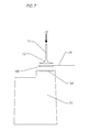
- FIG. 7 is a schematic drawing of a preferred process of placing a new print head assembly over the FIG. 1 used cartridge housing;
- FIG. 8 is a schematic drawing showing affixation of the contact area of the new print head assembly onto the FIG. 1 cartridge housing.
- FIG. 1 used inkjet printer cartridge 2 , having a plastic housing 4 , a cap 6 , a print head assembly 8 containing a flexible board 10 that is electrically integrated with the print head 12 , and electrical contacts 14 that engage the contacts inside the cradle of the printer are shown.
- the used inkjet cartridge 2 includes housing 4 , cap and foam 16 .
- the foam 16 contains ink, and ink filter 18 prevents contaminants and relatively large ink particles from penetrating through the print head 12 and through the ink delivery tunnel 22 .
- the tunnel 22 is also referred to as the “chimney”.
- Print head assembly 8 , flexible board 10 , print head 12 and the electrical contacts 14 are also shown.
- the used inkjet cartridge 2 , housing 4 , delivery tunnel or chimney 22 and cartridge ink delivery duct 24 are shown. It is believed that the adhesive is dispensed around the cartridge ink delivery duct 24 over the surface 26 and once the print head is placed, not shown, it is believed that the adhesive residues on surface 26 are pushed to adhesive run out tunnels or channels 28 and 30 in order to prevent contamination of adhesive in the ink delivery duct 24 .
- new print head assembly 32 contains flexible board 34 and electrical contacts 36 . These contacts engage with corresponding contacts located inside the printer cradle, not shown, to form a complete electrical circuit that controls and enables printing. Also shown are nozzle plate 37 and adhesive beads 38 and 40 . Nozzle plate 37 dispenses the ink directly onto the printed media through the microscopic nozzles 44 . Electrical wires 46 are in electrical communication with the print head chambers, not shown, and with the electrical contacts 36 .
- Print head 48 print head ink delivery duct 50 , electrical wires 46 and hot melt adhesive film 52 are shown.
- the adhesive film 52 functions to adhere the print head assembly to the cartridge housing with application of pressure and heat.
- a preferred process of removing the used print head and removing the used print head adhesive from the prior art cartridge housing 4 by means of routing is described with reference to FIG. 6 .
- the flexible board with the contacts is first removed using heat and pointed pliers.
- the original print head has been adhered to the housing with a strong thermosetting adhesive that creates a bond that cannot be broken by the use of heat alone. Therefore when removing the used flexible board from the housing, the used print head 12 typically detaches from the flexible board and stays bonded to the cartridge.
- a routing CNC machine is used with an appropriate routing bit 53 that is rotated at relatively high speed, for example several thousand rpm, in the direction of the arrow 56 and progresses linearly in the direction of arrow 57 to remove the used print head 12 and the used adhesive 58 that remains on adhesive surface 26 , as shown in FIG. 3 .
- a new, clean surface 60 is formed by the routing process to form a surface upon which new adhesive is dispensed.
- Holding fixture 62 is adapted to retain swivel locking bar 64 .
- the locking bar 64 is adapted to swivels in the direction of arrow 66 , and, once locked by pin 68 , the fixture 62 keeps the cartridge stable during the routing process.
- the print head area of the new print head assembly 34 is installed over, that is, on the modified cartridge housing 70 .
- New print head 48 is pressed on top of the dispensed adhesive, not shown, at the desired or pre-determined position, and over the newly routed surface 60 .
- Robotic arm 71 equipped with suction cup 72 that holds the print head, moves the print head in the direction of arrow 74 and into the desired, predetermined position. Once the print head is in place, the vacuum on suction cup 72 is released and the arm 71 moves back to its original position and in the opposite direction of arrow 74 .
- the contact area 36 of the new print head assembly 34 is installed by swivel robotic arm 76 that swivels in the direction of arrow 78 and pushes the print head assembly contact area 36 over the modified cartridge housing 70 .
- Heating pad 80 then generates heat and in combination with arm 76 , pressure is generated sufficient to activate the hot melt adhesive film 52 that then adheres the print head to the cartridge housing 70 .
- the present system and process is directed to aspects of remanufacturing a cartridge, a description of the operation of a conventional inkjet printer cartridge, print-head and the process of making the print head is found in U.S. Pat. No. 6,293,664 and U.S. Pat. No. 6,310,641.
- the present systems and processes relate to an inkjet cartridge print head made by thermal-jet technology or piezo-electric jet technology were the print head assembly is integrated on the ink container and not inside of the printer, separated from the ink reservoir.
- a thermal jet inkjet print head operates by dispensing ink through a set of microscopic nozzles that are located over a microscopic chamber.
- a heating element or a resistor is installed at the bottom of the chamber that contains the inkjet ink. As the resistor receives an electrical pulse through the electrical microscopic wires it heats up. The heating element heats up for a definite period of time. The heating of the resistor causes a local evaporation of the ink in the resistor's surrounding. The built-up pressure from the evaporation process pushes the ink through the nozzle on the nozzle plate and to the outside of the chamber and then over the printed media.
- a print made by an inkjet printer is in reality a puzzle of thousands or even millions of microscopic drops with a volume in the range of a 1-10 Pico-liters.
- the ink drops are dispensed next to each other and on top of each other to create the image and its different tones. If the image is in gray scale a certain number of drops on top of each other will produce, for example, a black tone whereas fewer drops will produce a gray tone.
- the different colors and tones are generated by mixing, for example, the three basic colors: cyan, magenta and yellow to produce the entire color and tone gamut or ranged.
- Preparation preferably includes removing the used cap in order to reach the internal components of the cartridges, such as the foam and the filter. In some occasions the cartridge cannot be refilled without removing the cap.
- the cap can be removed by any conventional means such as cutting, splitting or popping using pressure on both sides of the cartridges housing.
- the foam is taken out for washing or re-washing.
- the foam can be used for another cycle by washing and drying it or it is possible as well to replace the used foam with a new foam.
- the filter is removed as well. Removing the filter is not a necessity but is preferably because such removal can reduce the time it takes to wash the cartridge housing, especially in the ducting areas 22 , 24 as shown in FIG. 3 , below the ink filter 18 , as shown in FIG. 2 , and above the print head 12 , as shown in FIG. 1 . Often times, the used ink dries up inside the ducting area and cannot be cleaned out without removing the filter, especially when dealing with pigmented ink systems.
- the print head assembly is preferably put in an oven at 100-140 degrees F. for 5-30 minutes in order to loosen the adhesion between the hot melt adhesive on the original flexible board and the cartridge housing.
- the cartridge is taken out of the oven and the flexible board, including the contacts, is removed using a spatula or a similar tool.
- the print head then tears from the flexible board but remains attached to the cartridge housing because the prior art adhesive is a thermosetting polymer that doesn't change is viscosity once heated to those temperatures.
- the original print head is preferably removed by a router in combination with a CNC machine.
- Accurate removal of the print head and adhesive is an advantageous feature of the present system and methods, whereby a new mounting surface 60 is created, as shown in FIG. 6 , for the new print head and new adhesive.
- the most preferred accuracy in regard to this aspect of the process is 0.001 to 0.005 inch.
- the pre-programmed CNC routing machine cuts out the prior art print head 12 , as shown in FIG. 1 , and the used adhesive as shown in and described with reference to FIG. 6 .
- the cartridge is washed and dried.
- This process can be done by any washing means such as manually washing under a sink, in a conveyor washing machine or a tray with water spray.
- the drying process can be done using a convection oven, blowing air or a conveyor oven.
- the cartridge housing is preferably completely dry before the installation of the adhesive is conducted in order to assure that there is no moisture inside or outside of the cartridge housing that can later affect the bond quality.
- a new filter is then preferably installed with a soldering iron having substantially the same shape and dimensions of the chimney.
- the filter is placed, preferably with a pneumatic machine that applies the filter with an aligning fixture and affixes the filter on top of the chimney using heat and pressure for a predetermined of time sufficient to achieve a sturdy assembly.
- the process includes dispensing the print head adhesive, placing the print head area of the new print head assembly over the modified housing, and placing the contact area of the new print head assembly over the modified housing.
- the adhesive is applied with a conventional, automatic, preprogrammed XYZ robotic dispenser that uses a computer controlled dispensing mechanism that applies the adhesive on the newly made adhesive surface 60 , as shown in FIG. 6 .
- the adhesive is applied around the cartridge ink delivery duct 24 .
- the adhesive is a dual component epoxy system, chosen to achieve good dimensional stability, great bond strength and high resistance to humidity and water. Other types of adhesive systems can be used so long as they function to achieve the above properties and meet the above criteria.
- a preferred print head side installation is shown in and described above with respect to FIG. 7 .
- the print head assembly preferably is aligned using a fixture that holds the print head assembly and applies it using a pneumatic arm to that that print head is positioned at the exact, pre-determined location on the newly routed surface 60 as shown in FIG. 6 .
- the system is then heat cured in order to prevent disconnection of the print head assembly from the cartridge housing.
- the contact area of the new print head assembly preferably is affixed to the cartridge housing as can be seen in FIG. 8 .
- the head assembly is bent over the cartridge housing. Then heat and pressure are applied sufficient to activate the hot melt layer on the inner side of the print head assembly.
- the specific heat and pressure required are specific to the adhesive used, as will be appreciated by a person skilled in this field.
- the cartridge is then electrically tested for any malfunction in the print head assembly due to the installation process.
- the foam is inserted and the cartridge is filled with ink.
- a new cap or the used cap is installed or re-installed, preferably by means of ultrasonic welding as described in U.S. Pat. No. 6,773,087.
- the cartridge may be tested in order to assure the print quality or the cartridge could be packed for shipping without further testing.
Abstract
Description
Claims (6)
Priority Applications (1)
| Application Number | Priority Date | Filing Date | Title |
|---|---|---|---|
| US14/594,246 US9162470B2 (en) | 2008-02-11 | 2015-01-12 | Remanufactured inkjet printer cartridge, system and process |
Applications Claiming Priority (5)
| Application Number | Priority Date | Filing Date | Title |
|---|---|---|---|
| US2775408P | 2008-02-11 | 2008-02-11 | |
| US12/368,959 US8011771B2 (en) | 2008-02-11 | 2009-02-10 | Remanufactured inkjet printer cartridge, system and process |
| US13/195,557 US8602542B2 (en) | 2008-02-11 | 2011-08-01 | Remanufactured inkjet printer cartridge, system and process |
| US13/956,168 US9102161B2 (en) | 2008-02-11 | 2013-07-31 | Remanufactured inkjet printer cartridge, system and process |
| US14/594,246 US9162470B2 (en) | 2008-02-11 | 2015-01-12 | Remanufactured inkjet printer cartridge, system and process |
Related Parent Applications (1)
| Application Number | Title | Priority Date | Filing Date |
|---|---|---|---|
| US13/956,168 Continuation US9102161B2 (en) | 2008-02-11 | 2013-07-31 | Remanufactured inkjet printer cartridge, system and process |
Publications (2)
| Publication Number | Publication Date |
|---|---|
| US20150121699A1 US20150121699A1 (en) | 2015-05-07 |
| US9162470B2 true US9162470B2 (en) | 2015-10-20 |
Family
ID=40938524
Family Applications (4)
| Application Number | Title | Priority Date | Filing Date |
|---|---|---|---|
| US12/368,959 Expired - Fee Related US8011771B2 (en) | 2008-02-11 | 2009-02-10 | Remanufactured inkjet printer cartridge, system and process |
| US13/195,557 Active US8602542B2 (en) | 2008-02-11 | 2011-08-01 | Remanufactured inkjet printer cartridge, system and process |
| US13/956,168 Expired - Fee Related US9102161B2 (en) | 2008-02-11 | 2013-07-31 | Remanufactured inkjet printer cartridge, system and process |
| US14/594,246 Active US9162470B2 (en) | 2008-02-11 | 2015-01-12 | Remanufactured inkjet printer cartridge, system and process |
Family Applications Before (3)
| Application Number | Title | Priority Date | Filing Date |
|---|---|---|---|
| US12/368,959 Expired - Fee Related US8011771B2 (en) | 2008-02-11 | 2009-02-10 | Remanufactured inkjet printer cartridge, system and process |
| US13/195,557 Active US8602542B2 (en) | 2008-02-11 | 2011-08-01 | Remanufactured inkjet printer cartridge, system and process |
| US13/956,168 Expired - Fee Related US9102161B2 (en) | 2008-02-11 | 2013-07-31 | Remanufactured inkjet printer cartridge, system and process |
Country Status (1)
| Country | Link |
|---|---|
| US (4) | US8011771B2 (en) |
Cited By (1)
| Publication number | Priority date | Publication date | Assignee | Title |
|---|---|---|---|---|
| US9818249B1 (en) | 2002-09-04 | 2017-11-14 | Copilot Ventures Fund Iii Llc | Authentication method and system |
Families Citing this family (4)
| Publication number | Priority date | Publication date | Assignee | Title |
|---|---|---|---|---|
| WO2007030504A2 (en) * | 2005-09-07 | 2007-03-15 | Retail Inkjet Solutions | System and method for refilling inkjet cartridges |
| US8011771B2 (en) * | 2008-02-11 | 2011-09-06 | Wazana Brothers International, Inc. | Remanufactured inkjet printer cartridge, system and process |
| CN110143058B (en) * | 2018-09-20 | 2020-04-28 | 杭州旗捷科技有限公司 | Ink cartridge recycling apparatus and recycled ink cartridge |
| CN109572222B (en) * | 2018-10-23 | 2020-02-14 | 珠海艾派克微电子有限公司 | Recycled ink box, electronic patch and recycled ink box forming method |
Citations (51)
| Publication number | Priority date | Publication date | Assignee | Title |
|---|---|---|---|---|
| US5345315A (en) | 1988-11-23 | 1994-09-06 | Imatec, Ltd. | Method and system for improved tone and color reproduction of electronic image on hard copy using a closed loop control |
| US5552816A (en) | 1992-05-29 | 1996-09-03 | Fuji Xerox Co., Ltd. | Ink tank, ink-jet cartridge and ink-jet recording apparatus |
| US5589862A (en) | 1992-07-31 | 1996-12-31 | Canon Kabushiki Kaisha | Liquid storing container for recording apparatus |
| EP0794059A2 (en) | 1996-03-05 | 1997-09-10 | Hewlett-Packard Company | Pressure regulator free ink ink jet pen |
| EP0546832B1 (en) | 1991-12-11 | 1998-03-25 | Canon Kabushiki Kaisha | Carriage for ink jet recording apparatus |
| US5754197A (en) | 1994-05-31 | 1998-05-19 | Hewlett-Packard Company | Cleaner cartridge for an inkjet printing mechanism |
| US6065824A (en) | 1994-12-22 | 2000-05-23 | Hewlett-Packard Company | Method and apparatus for storing information on a replaceable ink container |
| US6149857A (en) | 1995-08-01 | 2000-11-21 | Loctite (R&D) Limited | Method of making films and coatings having anisotropic conductive pathways therein |
| US6161915A (en) | 1998-06-19 | 2000-12-19 | Lexmark International, Inc | Identification of thermal inkjet printer cartridges |
| US6325475B1 (en) | 1996-09-06 | 2001-12-04 | Microfab Technologies Inc. | Devices for presenting airborne materials to the nose |
| US6379876B1 (en) | 2000-06-13 | 2002-04-30 | Eastman Kodak Company | Thermally processable imaging element comprising an ion exchanged reducing agent |
| US6402876B1 (en) | 1997-08-01 | 2002-06-11 | Loctite (R&D) Ireland | Method of forming a monolayer of particles, and products formed thereby |
| EP1247651A2 (en) | 2001-04-03 | 2002-10-09 | Seiko Epson Corporation | Ink cartridge |
| US6509126B1 (en) | 2001-12-28 | 2003-01-21 | Eastman Kodak Company | Photothermographic element comprising a fluorescent dye and methods of image formation |
| EP0816102B1 (en) | 1996-06-27 | 2003-08-20 | Canon Kabushiki Kaisha | Recording method using large and small dots |
| US20040066429A1 (en) | 2002-10-07 | 2004-04-08 | Yoel Wazana | Resealed ink cartridge and method of manufacture |
| US20040155945A1 (en) | 2003-02-07 | 2004-08-12 | Dong-Sun Kim | Printing apparatus and electronic device having line contact structure |
| WO2004096558A1 (en) | 2003-04-25 | 2004-11-11 | Canon Kabushiki Kaisha | Ink cartridge, recording apparatus employing ink cartridge, and manufacturing method for ink cartridge |
| US6834937B2 (en) * | 2002-08-13 | 2004-12-28 | Lexmark International, Inc. | Printhead corrosion protection |
| US6837565B2 (en) | 2000-08-07 | 2005-01-04 | Dynamic Cassette International Ltd. | Printer cartridge kit and method |
| US6882810B2 (en) | 2003-08-15 | 2005-04-19 | Static Control Components, Inc. | Method and apparatus for repairing and electronic circuit in a remanufactured replaceable consumable |
| US20060053030A1 (en) | 2004-09-07 | 2006-03-09 | Hiroto Nakamura | Method of recycling a liquid cartridge |
| US7027660B2 (en) | 2001-07-11 | 2006-04-11 | Ecole Polytechnique Federale De Lausanne (Epfl) | Images incorporating microstructures |
| EP1078759B1 (en) | 1999-08-24 | 2006-08-02 | Canon Kabushiki Kaisha | Liquid ejection type print head, printing apparatus provided with same and a method for producing a liquid ejection type print head |
| US7139493B2 (en) | 1999-09-30 | 2006-11-21 | Fuji Photo Film Co., Ltd. | Method, device, system and recording medium for detecting improper cartridge, and cartridge |
| EP1088668B1 (en) | 1999-10-01 | 2007-01-10 | Hewlett-Packard Company, A Delaware Corporation | Method and apparatus for transferring information between a printer portion and a replaceable printing component |
| US7207483B2 (en) | 2003-04-07 | 2007-04-24 | Silverbrook Research Pty Ltd | Shopping receptacle with in-built user interface |
| US7254346B2 (en) | 2004-08-13 | 2007-08-07 | Static Control Components, Inc. | Systems and methods for universal imaging components |
| US7289156B2 (en) | 1997-07-15 | 2007-10-30 | Silverbrook Research Pty Ltd | Optical data card reader |
| US20070263044A1 (en) | 2006-05-09 | 2007-11-15 | Shui Kuen Nip | Chip retaining device of ink cartridge used in ink-jet printer |
| US7328974B2 (en) | 2005-09-29 | 2008-02-12 | Alex Kuo-Shen Wang | Inkjet printer ink cartridge |
| US7399052B1 (en) | 2005-03-25 | 2008-07-15 | Anderson Stephen A | Renovated ink jet cartridge and method of renovating |
| US20080253799A1 (en) | 2007-04-10 | 2008-10-16 | Static Control Components, Inc. | Method for converting a non-chipped imaging cartridge to a multi-use chipped imaging cartridge |
| US7483053B2 (en) | 1998-07-10 | 2009-01-27 | Silverbrook Research Pty Ltd | Combined camera and printer assembly with a card reader for image processing instructions |
| US20090058958A1 (en) | 2007-08-27 | 2009-03-05 | Alex Kuo-Shen Wang | Environmental protection ink cartridge / toner cartridge automatic refill chip |
| US7515837B2 (en) | 2007-01-17 | 2009-04-07 | Static Control Components, Inc. | System and methods for universal imaging components |
| US7640181B2 (en) | 2000-02-17 | 2009-12-29 | Hart Intercivic, Inc. | Distributed network voting system |
| US7875463B2 (en) | 2004-03-26 | 2011-01-25 | Agilent Technologies, Inc. | Generalized pulse jet ejection head control model |
| US7874639B2 (en) | 2005-11-25 | 2011-01-25 | Canon Kabushiki Kaisha | Ink jet recording head, ink jet cartridge with ink jet recording head, and ink jet recording apparatus |
| WO2011018003A1 (en) | 2009-08-11 | 2011-02-17 | 珠海天威技术开发有限公司 | Chip and method for resetting data about remaining amount of consumable |
| US7894729B2 (en) | 2005-12-28 | 2011-02-22 | Park & Opc Co. Ltd. | Microchip and method for repairing cartridge |
| US20110085310A1 (en) | 2009-10-09 | 2011-04-14 | Cachia Joseph M | Space saving circuit board |
| US20110128567A1 (en) | 2009-10-30 | 2011-06-02 | Joseph Cachia | Replacement Printer Cartridge Chip With A Microcontroller With An Encrypted Memory Device |
| US7971947B2 (en) | 2008-04-07 | 2011-07-05 | Static Control Components, Inc. | Systems and methods for remanufacturing imaging components |
| US7988257B2 (en) | 2008-02-05 | 2011-08-02 | Samsung Electronics Co., Ltd. | Ink cartridge, image forming apparatus, and method to manufacture ink cartridge |
| US8061826B2 (en) | 2008-07-31 | 2011-11-22 | Static Control Components, Inc. | Methods and devices for remanufacturing an imaging cartridge |
| US8160473B2 (en) | 2008-12-08 | 2012-04-17 | Static Control Components, Inc. | Imaging apparatus and methods |
| US8171567B1 (en) | 2002-09-04 | 2012-05-01 | Tracer Detection Technology Corp. | Authentication method and system |
| US8259351B2 (en) | 2008-03-13 | 2012-09-04 | Seiko Epson Corporation | Electronic device system and control method of electronic device system |
| US8262201B2 (en) | 2007-04-10 | 2012-09-11 | Hewlett-Packard Development Company, L.P. | Micro writing and reading |
| US8287204B2 (en) | 2008-06-23 | 2012-10-16 | Silverbrook Research Pty Ltd | Electronic pen with retractable and replaceable cartridge |
Family Cites Families (1)
| Publication number | Priority date | Publication date | Assignee | Title |
|---|---|---|---|---|
| US8011771B2 (en) * | 2008-02-11 | 2011-09-06 | Wazana Brothers International, Inc. | Remanufactured inkjet printer cartridge, system and process |
-
2009
- 2009-02-10 US US12/368,959 patent/US8011771B2/en not_active Expired - Fee Related
-
2011
- 2011-08-01 US US13/195,557 patent/US8602542B2/en active Active
-
2013
- 2013-07-31 US US13/956,168 patent/US9102161B2/en not_active Expired - Fee Related
-
2015
- 2015-01-12 US US14/594,246 patent/US9162470B2/en active Active
Patent Citations (54)
| Publication number | Priority date | Publication date | Assignee | Title |
|---|---|---|---|---|
| US5345315A (en) | 1988-11-23 | 1994-09-06 | Imatec, Ltd. | Method and system for improved tone and color reproduction of electronic image on hard copy using a closed loop control |
| EP0546832B1 (en) | 1991-12-11 | 1998-03-25 | Canon Kabushiki Kaisha | Carriage for ink jet recording apparatus |
| US5552816A (en) | 1992-05-29 | 1996-09-03 | Fuji Xerox Co., Ltd. | Ink tank, ink-jet cartridge and ink-jet recording apparatus |
| US5589862A (en) | 1992-07-31 | 1996-12-31 | Canon Kabushiki Kaisha | Liquid storing container for recording apparatus |
| US5754197A (en) | 1994-05-31 | 1998-05-19 | Hewlett-Packard Company | Cleaner cartridge for an inkjet printing mechanism |
| US6065824A (en) | 1994-12-22 | 2000-05-23 | Hewlett-Packard Company | Method and apparatus for storing information on a replaceable ink container |
| US6149857A (en) | 1995-08-01 | 2000-11-21 | Loctite (R&D) Limited | Method of making films and coatings having anisotropic conductive pathways therein |
| EP0794059A2 (en) | 1996-03-05 | 1997-09-10 | Hewlett-Packard Company | Pressure regulator free ink ink jet pen |
| EP0816102B1 (en) | 1996-06-27 | 2003-08-20 | Canon Kabushiki Kaisha | Recording method using large and small dots |
| US6325475B1 (en) | 1996-09-06 | 2001-12-04 | Microfab Technologies Inc. | Devices for presenting airborne materials to the nose |
| US7289156B2 (en) | 1997-07-15 | 2007-10-30 | Silverbrook Research Pty Ltd | Optical data card reader |
| US6402876B1 (en) | 1997-08-01 | 2002-06-11 | Loctite (R&D) Ireland | Method of forming a monolayer of particles, and products formed thereby |
| US6161915A (en) | 1998-06-19 | 2000-12-19 | Lexmark International, Inc | Identification of thermal inkjet printer cartridges |
| US7483053B2 (en) | 1998-07-10 | 2009-01-27 | Silverbrook Research Pty Ltd | Combined camera and printer assembly with a card reader for image processing instructions |
| EP1078759B1 (en) | 1999-08-24 | 2006-08-02 | Canon Kabushiki Kaisha | Liquid ejection type print head, printing apparatus provided with same and a method for producing a liquid ejection type print head |
| US7139493B2 (en) | 1999-09-30 | 2006-11-21 | Fuji Photo Film Co., Ltd. | Method, device, system and recording medium for detecting improper cartridge, and cartridge |
| EP1088668B1 (en) | 1999-10-01 | 2007-01-10 | Hewlett-Packard Company, A Delaware Corporation | Method and apparatus for transferring information between a printer portion and a replaceable printing component |
| US7640181B2 (en) | 2000-02-17 | 2009-12-29 | Hart Intercivic, Inc. | Distributed network voting system |
| US6379876B1 (en) | 2000-06-13 | 2002-04-30 | Eastman Kodak Company | Thermally processable imaging element comprising an ion exchanged reducing agent |
| US6837565B2 (en) | 2000-08-07 | 2005-01-04 | Dynamic Cassette International Ltd. | Printer cartridge kit and method |
| EP1247651A2 (en) | 2001-04-03 | 2002-10-09 | Seiko Epson Corporation | Ink cartridge |
| US7027660B2 (en) | 2001-07-11 | 2006-04-11 | Ecole Polytechnique Federale De Lausanne (Epfl) | Images incorporating microstructures |
| US6509126B1 (en) | 2001-12-28 | 2003-01-21 | Eastman Kodak Company | Photothermographic element comprising a fluorescent dye and methods of image formation |
| US6834937B2 (en) * | 2002-08-13 | 2004-12-28 | Lexmark International, Inc. | Printhead corrosion protection |
| US8171567B1 (en) | 2002-09-04 | 2012-05-01 | Tracer Detection Technology Corp. | Authentication method and system |
| US20070002106A1 (en) | 2002-10-07 | 2007-01-04 | Yoel Wazana | Resealed ink cartridge and method of manufacture |
| US6773087B2 (en) | 2002-10-07 | 2004-08-10 | Wazana Brothers International | Resealed ink cartridge and method of manufacture |
| US20040066429A1 (en) | 2002-10-07 | 2004-04-08 | Yoel Wazana | Resealed ink cartridge and method of manufacture |
| US20040155945A1 (en) | 2003-02-07 | 2004-08-12 | Dong-Sun Kim | Printing apparatus and electronic device having line contact structure |
| US7207483B2 (en) | 2003-04-07 | 2007-04-24 | Silverbrook Research Pty Ltd | Shopping receptacle with in-built user interface |
| WO2004096558A1 (en) | 2003-04-25 | 2004-11-11 | Canon Kabushiki Kaisha | Ink cartridge, recording apparatus employing ink cartridge, and manufacturing method for ink cartridge |
| US6882810B2 (en) | 2003-08-15 | 2005-04-19 | Static Control Components, Inc. | Method and apparatus for repairing and electronic circuit in a remanufactured replaceable consumable |
| US7875463B2 (en) | 2004-03-26 | 2011-01-25 | Agilent Technologies, Inc. | Generalized pulse jet ejection head control model |
| US7254346B2 (en) | 2004-08-13 | 2007-08-07 | Static Control Components, Inc. | Systems and methods for universal imaging components |
| US20060053030A1 (en) | 2004-09-07 | 2006-03-09 | Hiroto Nakamura | Method of recycling a liquid cartridge |
| US7399052B1 (en) | 2005-03-25 | 2008-07-15 | Anderson Stephen A | Renovated ink jet cartridge and method of renovating |
| US7328974B2 (en) | 2005-09-29 | 2008-02-12 | Alex Kuo-Shen Wang | Inkjet printer ink cartridge |
| US7874639B2 (en) | 2005-11-25 | 2011-01-25 | Canon Kabushiki Kaisha | Ink jet recording head, ink jet cartridge with ink jet recording head, and ink jet recording apparatus |
| US7894729B2 (en) | 2005-12-28 | 2011-02-22 | Park & Opc Co. Ltd. | Microchip and method for repairing cartridge |
| US20070263044A1 (en) | 2006-05-09 | 2007-11-15 | Shui Kuen Nip | Chip retaining device of ink cartridge used in ink-jet printer |
| US7515837B2 (en) | 2007-01-17 | 2009-04-07 | Static Control Components, Inc. | System and methods for universal imaging components |
| US20080253799A1 (en) | 2007-04-10 | 2008-10-16 | Static Control Components, Inc. | Method for converting a non-chipped imaging cartridge to a multi-use chipped imaging cartridge |
| US8262201B2 (en) | 2007-04-10 | 2012-09-11 | Hewlett-Packard Development Company, L.P. | Micro writing and reading |
| US20090058958A1 (en) | 2007-08-27 | 2009-03-05 | Alex Kuo-Shen Wang | Environmental protection ink cartridge / toner cartridge automatic refill chip |
| US7988257B2 (en) | 2008-02-05 | 2011-08-02 | Samsung Electronics Co., Ltd. | Ink cartridge, image forming apparatus, and method to manufacture ink cartridge |
| US8259351B2 (en) | 2008-03-13 | 2012-09-04 | Seiko Epson Corporation | Electronic device system and control method of electronic device system |
| US7971947B2 (en) | 2008-04-07 | 2011-07-05 | Static Control Components, Inc. | Systems and methods for remanufacturing imaging components |
| US8297868B2 (en) | 2008-06-23 | 2012-10-30 | Silverbrook Research Pty Ltd | Retractable electronic pen comprising actuator button decoupled from force sensor |
| US8287204B2 (en) | 2008-06-23 | 2012-10-16 | Silverbrook Research Pty Ltd | Electronic pen with retractable and replaceable cartridge |
| US8061826B2 (en) | 2008-07-31 | 2011-11-22 | Static Control Components, Inc. | Methods and devices for remanufacturing an imaging cartridge |
| US8160473B2 (en) | 2008-12-08 | 2012-04-17 | Static Control Components, Inc. | Imaging apparatus and methods |
| WO2011018003A1 (en) | 2009-08-11 | 2011-02-17 | 珠海天威技术开发有限公司 | Chip and method for resetting data about remaining amount of consumable |
| US20110085310A1 (en) | 2009-10-09 | 2011-04-14 | Cachia Joseph M | Space saving circuit board |
| US20110128567A1 (en) | 2009-10-30 | 2011-06-02 | Joseph Cachia | Replacement Printer Cartridge Chip With A Microcontroller With An Encrypted Memory Device |
Non-Patent Citations (1)
| Title |
|---|
| International Search Report and Written Opinion, International Application No. PCT/US2014/015046, Jul. 3, 2014, 10 pages, European Patent Office, HV Rijswijk, NL-2280. |
Cited By (1)
| Publication number | Priority date | Publication date | Assignee | Title |
|---|---|---|---|---|
| US9818249B1 (en) | 2002-09-04 | 2017-11-14 | Copilot Ventures Fund Iii Llc | Authentication method and system |
Also Published As
| Publication number | Publication date |
|---|---|
| US8602542B2 (en) | 2013-12-10 |
| US9102161B2 (en) | 2015-08-11 |
| US20150121699A1 (en) | 2015-05-07 |
| US20130312262A1 (en) | 2013-11-28 |
| US20110283536A1 (en) | 2011-11-24 |
| US20090201349A1 (en) | 2009-08-13 |
| US8011771B2 (en) | 2011-09-06 |
Similar Documents
| Publication | Publication Date | Title |
|---|---|---|
| US9162470B2 (en) | Remanufactured inkjet printer cartridge, system and process | |
| JP5738018B2 (en) | Ink jet recording head and manufacturing method thereof | |
| JP3908800B2 (en) | Inkjet print cartridge | |
| JP3625925B2 (en) | Method for encapsulating conductive wires in a circuit | |
| KR100657108B1 (en) | Inkjet printhead having improved reliability | |
| JP4353833B2 (en) | Inkjet printhead package | |
| US7980196B2 (en) | Apparatus and method for coating polyimide layer | |
| JP3625924B2 (en) | How to install a flexible interconnect circuit assembly | |
| JP3917678B2 (en) | Attaching the printhead to the cartridge | |
| RU2651259C1 (en) | Molded ink supply device | |
| US6206507B1 (en) | Printer | |
| EP2230083B1 (en) | Remanufactured inkjet printer cartridge, system and process | |
| JP7009767B2 (en) | Liquid discharge head, liquid discharge unit, liquid discharge device | |
| JPH08207311A (en) | Ink jet cartridge | |
| US10059106B2 (en) | Liquid ejecting head and liquid ejecting apparatus | |
| JP2022135342A (en) | Print material storage container | |
| JP2005022229A (en) | Pressure damper and method for manufacturing the same, and ink jet recorder | |
| US20020075368A1 (en) | Packaging method and structure of an inkjet cartridge print head chip | |
| JP3601363B2 (en) | Ink jet recording apparatus and method of manufacturing the same | |
| KR101897061B1 (en) | Cartridge recycling method using FPCB for ink cartridge reproduction | |
| JP2004223832A (en) | Inkjet recording head and inkjet recorder | |
| JP2024053510A (en) | Method for manufacturing a liquid jet head | |
| JP2004113958A (en) | Polymer film formation apparatus | |
| JP2023127716A (en) | Liquid discharge head, head module, liquid discharge unit, and device for discharging liquid | |
| JP2023063954A (en) | Liquid discharge head, liquid discharge unit, and liquid discharge device |
Legal Events
| Date | Code | Title | Description |
|---|---|---|---|
| AS | Assignment |
Owner name: WAZANA BROTHERS INTERNATIONAL, INC. D/B/A MICRO SO Free format text: ASSIGNMENT OF ASSIGNORS INTEREST;ASSIGNORS:WAZANA, YOEL;SHANUN, SAGIE;PAULUS, JODA;REEL/FRAME:034888/0710 Effective date: 20110801 Owner name: MSE TECHNOLOGIES, LLC, ILLINOIS Free format text: ASSIGNMENT OF ASSIGNORS INTEREST;ASSIGNOR:WAZANA BROTHERS INTERNATIONAL, INC., D/B/A MICRO SOLUTIONS ENTERPRISES;REEL/FRAME:034888/0863 Effective date: 20140718 Owner name: CLOVER TECHNOLOGIES GROUP, LLC, ILLINOIS Free format text: ASSIGNMENT OF ASSIGNORS INTEREST;ASSIGNOR:MSE TECHNOLOGIES, LLC;REEL/FRAME:034904/0861 Effective date: 20140723 |
|
| STCF | Information on status: patent grant |
Free format text: PATENTED CASE |
|
| CC | Certificate of correction | ||
| RF | Reissue application filed |
Effective date: 20171019 |
|
| MAFP | Maintenance fee payment |
Free format text: PAYMENT OF MAINTENANCE FEE, 4TH YEAR, LARGE ENTITY (ORIGINAL EVENT CODE: M1551); ENTITY STATUS OF PATENT OWNER: LARGE ENTITY Year of fee payment: 4 |
|
| AS | Assignment |
Owner name: BANK OF AMERICA, N.A., AS AGENT, NORTH CAROLINA Free format text: SECURITY INTEREST;ASSIGNOR:CLOVER TECHNOLOGIES GROUP, LLC;REEL/FRAME:049988/0106 Effective date: 20190412 |
|
| AS | Assignment |
Owner name: CLOVER IMAGING GROUP, LLC, ILLINOIS Free format text: ASSIGNMENT OF ASSIGNORS INTEREST;ASSIGNOR:CLOVER TECHNOLOGIES GROUP, LLC;REEL/FRAME:051366/0525 Effective date: 20191216 |
|
| AS | Assignment |
Owner name: PNC BANK, NATIONAL ASSOCIATION, PENNSYLVANIA Free format text: SECURITY INTEREST;ASSIGNORS:CLOVER IMAGING GROUP, LLC;LATIN PARTS HOLDINGS, LLC;CLOVER EU, LLC;AND OTHERS;REEL/FRAME:053448/0329 Effective date: 20191216 |
|
| MAFP | Maintenance fee payment |
Free format text: PAYMENT OF MAINTENANCE FEE, 8TH YEAR, LARGE ENTITY (ORIGINAL EVENT CODE: M1552); ENTITY STATUS OF PATENT OWNER: LARGE ENTITY Year of fee payment: 8 |