US9164621B2 - Stereoscopic display apparatus and stereoscopic shooting apparatus, dominant eye judging method and dominant eye judging program for use therein, and recording medium - Google Patents
Stereoscopic display apparatus and stereoscopic shooting apparatus, dominant eye judging method and dominant eye judging program for use therein, and recording medium Download PDFInfo
- Publication number
- US9164621B2 US9164621B2 US13/581,617 US201013581617A US9164621B2 US 9164621 B2 US9164621 B2 US 9164621B2 US 201013581617 A US201013581617 A US 201013581617A US 9164621 B2 US9164621 B2 US 9164621B2
- Authority
- US
- United States
- Prior art keywords
- image
- dominant eye
- stereoscopic
- viewpoint image
- display
- Prior art date
- Legal status (The legal status is an assumption and is not a legal conclusion. Google has not performed a legal analysis and makes no representation as to the accuracy of the status listed.)
- Expired - Fee Related, expires
Links
- 238000000034 method Methods 0.000 title claims description 95
- 238000010586 diagram Methods 0.000 description 31
- 230000007704 transition Effects 0.000 description 28
- 241000283973 Oryctolagus cuniculus Species 0.000 description 26
- 210000005069 ears Anatomy 0.000 description 26
- 230000004048 modification Effects 0.000 description 17
- 238000012986 modification Methods 0.000 description 17
- 230000008569 process Effects 0.000 description 12
- 230000000007 visual effect Effects 0.000 description 10
- 210000003128 head Anatomy 0.000 description 7
- 238000001514 detection method Methods 0.000 description 2
- 239000004973 liquid crystal related substance Substances 0.000 description 2
- 230000004888 barrier function Effects 0.000 description 1
- 238000012850 discrimination method Methods 0.000 description 1
- 230000000694 effects Effects 0.000 description 1
- 230000006870 function Effects 0.000 description 1
- 238000003384 imaging method Methods 0.000 description 1
- 238000003825 pressing Methods 0.000 description 1
Images


Classifications
-
- G—PHYSICS
- G06—COMPUTING; CALCULATING OR COUNTING
- G06F—ELECTRIC DIGITAL DATA PROCESSING
- G06F3/00—Input arrangements for transferring data to be processed into a form capable of being handled by the computer; Output arrangements for transferring data from processing unit to output unit, e.g. interface arrangements
- G06F3/01—Input arrangements or combined input and output arrangements for interaction between user and computer
- G06F3/03—Arrangements for converting the position or the displacement of a member into a coded form
- G06F3/041—Digitisers, e.g. for touch screens or touch pads, characterised by the transducing means
- G06F3/0416—Control or interface arrangements specially adapted for digitisers
- G06F3/0418—Control or interface arrangements specially adapted for digitisers for error correction or compensation, e.g. based on parallax, calibration or alignment
-
- G—PHYSICS
- G06—COMPUTING; CALCULATING OR COUNTING
- G06F—ELECTRIC DIGITAL DATA PROCESSING
- G06F3/00—Input arrangements for transferring data to be processed into a form capable of being handled by the computer; Output arrangements for transferring data from processing unit to output unit, e.g. interface arrangements
- G06F3/01—Input arrangements or combined input and output arrangements for interaction between user and computer
- G06F3/011—Arrangements for interaction with the human body, e.g. for user immersion in virtual reality
- G06F3/013—Eye tracking input arrangements
-
- H04N13/0018—
-
- H04N13/004—
-
- H04N13/0468—
-
- H—ELECTRICITY
- H04—ELECTRIC COMMUNICATION TECHNIQUE
- H04N—PICTORIAL COMMUNICATION, e.g. TELEVISION
- H04N13/00—Stereoscopic video systems; Multi-view video systems; Details thereof
- H04N13/10—Processing, recording or transmission of stereoscopic or multi-view image signals
- H04N13/106—Processing image signals
- H04N13/122—Improving the 3D impression of stereoscopic images by modifying image signal contents, e.g. by filtering or adding monoscopic depth cues
-
- H—ELECTRICITY
- H04—ELECTRIC COMMUNICATION TECHNIQUE
- H04N—PICTORIAL COMMUNICATION, e.g. TELEVISION
- H04N13/00—Stereoscopic video systems; Multi-view video systems; Details thereof
- H04N13/10—Processing, recording or transmission of stereoscopic or multi-view image signals
- H04N13/106—Processing image signals
- H04N13/156—Mixing image signals
-
- H—ELECTRICITY
- H04—ELECTRIC COMMUNICATION TECHNIQUE
- H04N—PICTORIAL COMMUNICATION, e.g. TELEVISION
- H04N13/00—Stereoscopic video systems; Multi-view video systems; Details thereof
- H04N13/30—Image reproducers
- H04N13/366—Image reproducers using viewer tracking
-
- G—PHYSICS
- G09—EDUCATION; CRYPTOGRAPHY; DISPLAY; ADVERTISING; SEALS
- G09G—ARRANGEMENTS OR CIRCUITS FOR CONTROL OF INDICATING DEVICES USING STATIC MEANS TO PRESENT VARIABLE INFORMATION
- G09G2320/00—Control of display operating conditions
- G09G2320/06—Adjustment of display parameters
-
- G—PHYSICS
- G09—EDUCATION; CRYPTOGRAPHY; DISPLAY; ADVERTISING; SEALS
- G09G—ARRANGEMENTS OR CIRCUITS FOR CONTROL OF INDICATING DEVICES USING STATIC MEANS TO PRESENT VARIABLE INFORMATION
- G09G2354/00—Aspects of interface with display user
-
- G—PHYSICS
- G09—EDUCATION; CRYPTOGRAPHY; DISPLAY; ADVERTISING; SEALS
- G09G—ARRANGEMENTS OR CIRCUITS FOR CONTROL OF INDICATING DEVICES USING STATIC MEANS TO PRESENT VARIABLE INFORMATION
- G09G3/00—Control arrangements or circuits, of interest only in connection with visual indicators other than cathode-ray tubes
- G09G3/001—Control arrangements or circuits, of interest only in connection with visual indicators other than cathode-ray tubes using specific devices not provided for in groups G09G3/02 - G09G3/36, e.g. using an intermediate record carrier such as a film slide; Projection systems; Display of non-alphanumerical information, solely or in combination with alphanumerical information, e.g. digital display on projected diapositive as background
- G09G3/003—Control arrangements or circuits, of interest only in connection with visual indicators other than cathode-ray tubes using specific devices not provided for in groups G09G3/02 - G09G3/36, e.g. using an intermediate record carrier such as a film slide; Projection systems; Display of non-alphanumerical information, solely or in combination with alphanumerical information, e.g. digital display on projected diapositive as background to produce spatial visual effects
Definitions
- the present invention relates to a stereoscopic display apparatus and stereoscopic shooting method and, in particular, to a technology of judging a dominant eye of a user by using the stereoscopic display apparatus.
- Patent Document 1 an apparatus has been suggested (Patent Document 1) in which, when an operation element is stereoscopically displayed on a screen and an operator touches a touch panel, an operation instruction to the operation element stereoscopically displayed by a stereoscopic display apparatus is detected based on coordinate data indicating the touched position, a parallax image of the operation element formed by a stereoscopic merging part is changed, and the shape of the operation element stereoscopically displayed on the stereoscopic display apparatus is changed.
- the operation element is represented by an image of a push-button-type switch
- the image of the switch is touched on the touch panel for ON/OFF, display of the image of the switch is changed to stereoscopic display or flat display according to ON/OFF, thereby improving operability.
- Patent Document 2 an operation panel apparatus has been suggested (Patent Document 2) in which a stereoscopic parallax image is displayed on a display part and is switched to a flat image before an operation is performed on a touch panel, thereby improving operability.
- Patent Document 3 a visual line direction detecting apparatus has been suggested (Patent Document 3) in which visual lines of both eyes of a driver are detected, a comparison is made between the detection results and a standard visual line movement pattern in a normal driving state according to the state of a road where a vehicle has traveled during a detection period, it is determined which of the visual lines of both eyes is similar to the visual line movement pattern, and then an eye with a visual line direction more similar to the visual line movement pattern is determined as a dominant eye.
- a place of the stereoscopic display object thought to have been touched is actually a position corresponding to the stereoscopic display object on either one viewpoint image of a left viewpoint image ((B) of FIG. 28 ) and a right viewpoint image ((C) of FIG. 28 ).
- Which of the corresponding point on the left viewpoint image and the corresponding point on the right viewpoint image is near the place touched on the stereoscopic display object depends on the dominant eye of the user.
- Patent Document 3 describes that the dominant eye of the driver is determined by using visual line direction detecting means detecting visual line directions of both eyes of the driver, the visual line direction detecting means and others are required, and therefore the dominant eye cannot be determined with ease.
- the present invention was made in view of the circumstances described above, and has an object of providing a stereoscopic display apparatus and stereoscopic shooting apparatus, dominant eye judging method and dominant eye judging program for use therein, and recording medium in which the dominant eye of the user can be judged with ease by using a stereoscopic display apparatus, position coordinates on a stereoscopic display screen intended by the user can be obtained by using the judgment result, and operability at a coordinate position input device such as a touch panel can be improved.
- a stereoscopic display apparatus includes a stereoscopic display part displaying a stereoscopic image formed of a left viewpoint image and a right viewpoint image, a coordinate input part inputting desired position coordinate on a display surface of the stereoscopic display part, a display control part causing the stereoscopic display part to display a dominant eye judgment image formed of a left viewpoint image and a right viewpoint image for judging a dominant eye of a user, the dominant eye judgment image representing different reference coordinates between the left viewpoint image and the right viewpoint image, an obtaining part obtaining the position coordinates inputted by the user via the coordinate input part for the dominant eye judgment image displayed on the stereoscopic display part, and a judging part judging the dominant eye of the user inputting the position coordinates via the coordinate input part based on the reference coordinates of the dominant eye judgment image formed of the left viewpoint image and the right viewpoint image and the obtained position coordinates, depending on whether the obtained position coordinates are near the reference coordinates
- the inputted position coordinates are obtained via the coordinate input part. Based on these obtained position coordinates and reference coordinates of the dominant eye judgment image, the dominant eye of the user is judged depending on whether “the obtained position coordinates are near reference coordinates of the left viewpoint image and reference coordinates of the right viewpoint image.” This is based on the fact that “the position coordinates inputted on the dominant eye judgment image formed of the left viewpoint image and the right viewpoint image are near the reference coordinates of the user's dominant-eye-side viewpoint image.”
- the display control part causes the stereoscopic display part to display an icon image for operation as the dominant eye judgment image. According to this, when a normal icon image is clicked for operation, a dominant eye judgment can be automatically performed inside the apparatus without letting the user be aware of the dominant eye judgment at all, and the judgment result can be utilized for another control.
- the display control part causes the stereoscopic display part to display a button image such as a start button or a login button as the dominant eye judgment image.
- a button image such as a start button or a login button
- the user performs a touch operation on the button image displayed on the stereoscopic display part without being aware of the dominant eye judgment. Therefore, in the stereoscopic display apparatus according to the third aspect, a dominant eye judgment can be automatically performed inside the apparatus without letting the user be aware of the dominant eye judgment at all.
- the button image for example, a button that is inevitably touched is preferable, such as a start button or a login button.
- the display control part causes the stereoscopic display part to display a slide bar image including a knob for operation as the dominant eye judgment image. With the position where the knob of the slide bar is touched, a user's dominant eye judgment can be made.
- the display control part causes the stereoscopic display part to display a line drawing as the dominant eye judgment image
- the judging part judges the dominant eye of the user tracing the line drawing based on an average distance between coordinates of each contour line of the dominant eye judgment image formed of the left viewpoint image and the right viewpoint image representing the line drawing and coordinates successively obtained by the coordinate input part by tracing the line drawing.
- the line drawing displayed on the stereoscopic display part is traced and, depending on the traced track is near the line drawing of the left viewpoint image or near the line drawing of the right viewpoint image, the user's dominant eye is judged.
- the line drawing a picture, graph, or the like that can be easily traced is preferable.
- the display control part causes the stereoscopic display part to display a unfinished picture or graphic as the dominant eye judgment image, and based on reference coordinates of the dominant eye judgment image formed of the left viewpoint image and the right viewpoint image representing the unfinished picture or graphic and position coordinates of a picture or graphic added to finish the unfinished picture or graphic by the coordinate input part, the judging part judges the dominant eye of the adding user.
- the user's dominant eye is judged depending on whether the position coordinates of the picture or graphic added to the unfinished picture or graphic of the left viewpoint image and the right viewpoint image are near the left viewpoint image or the right viewpoint image.
- the judging part judges a right eye as the dominant eye when the dominant eye of the user inputting the position coordinates via the coordinate input part cannot be judged. That is, if a dominant eye judgment cannot be made, since people with the right eye as the dominant eye are more than people with the left eye as the dominant eye, the right eye is judged as the dominant eye, thereby reducing an error in judgment as much as possible.
- the stereoscopic display apparatus in the stereoscopic display apparatus according to any one of the first to seventh aspects, includes a storing and registering part storing and registering information about the dominant eye of the user inside the apparatus.
- the information about the dominant eye of the user can be registered in the apparatus, thereby eliminating the need of judging the dominant eye every time.
- the storing and registering part automatically stores and registers the information about the dominant eye based on the judgment result by the judging part.
- the storing and registering part has a dominant eye information input part accepting information about the dominant eye of the user indicated and inputted from the user, and stores and registers the information about the dominant eye of the user accepted by the dominant eye information input part.
- the information about the dominant eye of the user can be automatically registered, or the user can determine his or her own dominant eye and register the dominant eye.
- the stereoscopic display apparatus in the stereoscopic display apparatus according to any one of the eighth to tenth aspects, includes a position input part accepting, via the coordinate input part, position coordinates of a desired target image on the stereoscopic image displayed on the stereoscopic display part, wherein the position coordinates accepted from the position input part are handled as a coordinate position on a dominant-eye-side viewpoint image from out of the left viewpoint image and the right viewpoint image of the stereoscopic image, the dominant-eye-side viewpoint image corresponding to the information about the dominant eye of the user registered in the storing and registering part.
- a deviation between the position coordinates intended by the user and position coordinates on the viewpoint image determined by the device side can be reduced, thereby improving operability of the coordinate input part.
- the coordinate input part is a touch panel provided on the display surface of the stereoscopic display part.
- the stereoscopic display apparatus in the stereoscopic display apparatus according to any one of the eighth to twelfth aspects, includes a display mode switching part switching between a 3D display mode for causing the stereoscopic display part to display the stereoscopic image formed of the left viewpoint image and the right viewpoint image and a 2D display mode for causing the stereoscopic display part to display either one viewpoint image from out of the left viewpoint image and the right viewpoint image configuring the stereoscopic image, wherein at the time of switching by the display mode switching part to the 2D display mode, the display control part causes the stereoscopic display part to display a user's dominant-eye-side viewpoint image from out of the left viewpoint image and the right viewpoint image based on the information about the dominant eye of the user registered in the storing and registering part.
- the coordinate input part is a touch panel provided on the display surface of the stereoscopic display part
- the display mode switching part alternately switches among the 2D display mode and the 3D display mode every time a touch is detected by the touch panel. With this, switching can be easily made between the 2D display mode and the 3D display mode.
- the coordinate input part is a touch panel provided on the display surface of the stereoscopic display part
- the display mode switching part switches to the 2D display mode when a touch is detected by the touch panel, and switches to the 3D display mode when a touch is not detected by the touch panel or a touch is not detected for a predetermined period of time or more.
- the stereoscopic display apparatus in the stereoscopic display apparatus according to any one of the eighth to fifteenth aspects, includes a parallax amount detecting part detecting parallax amounts of left and right of the stereoscopic image formed of the left viewpoint image and the right viewpoint image to be displayed on the stereoscopic display part, a region extracting part extracting a region having a parallax amount exceeding a parallax amount previously set or a parallax amount of a region appearing doubled and specified by the user from out of the parallax amounts detected by the parallax amount detecting part, and a image replacing part replacing a stereoscopic image of the region extracted by the region extracting part only by the user's dominant-eye-side viewpoint image corresponding to the information about the dominant eye of the user and registered in the storing and registering part.
- the region that appears doubled is replaced by a dominant-eye-side viewpoint image (the 2D image).
- the region to be replaced by a 2D image may be automatically extracted as a region with a parallax amount exceeding a predetermined parallax amount, or the region that appears doubled from the user may be specified by the coordinate input part.
- a stereoscopic imaging apparatus in a stereoscopic shooting apparatus including the stereoscopic display apparatus according to any one of the eighth to sixteenth aspects, includes a shooting mode switching part switching between a 2D shooting mode for shooting a two-dimensional image and a 3D shooting mode for shooting a stereoscopic image formed of a left viewpoint image and a right viewpoint image, and a control part causing the stereoscopic display part to display the user's dominant-eye-side viewpoint image corresponding to the information about the dominant eye of the user and registered in the storing and registering part from out of the left viewpoint image and the right viewpoint image when switching is made by the shooting mode switching part to the 2D shooting mode.
- An eighteenth aspect of the present invention is directed to a dominant eye judging method using a stereoscopic display apparatus having a stereoscopic display part and a coordinate input part inputting desired position coordinates on a display surface of the stereoscopic display part, the method including the steps of causing the stereoscopic display part to display a dominant eye judgment image formed of a left viewpoint image and a right viewpoint image for judging a dominant eye of a user, the dominant eye judgment image representing different reference coordinates between the left viewpoint image and the right viewpoint image, obtaining position coordinates inputted by the user via the coordinate input part for the dominant eye judgment image displayed on the stereoscopic display part, and a judging part judging the dominant eye of the user inputting the position coordinates via the coordinate input part based on the reference coordinates of the dominant eye judgment image formed of the left viewpoint image and the right viewpoint image and the obtained position coordinates, depending on whether the obtained position coordinates are near the reference coordinates of the left viewpoint image or the reference coordinates of the right viewpoint image.
- a nineteenth aspect of the present invention provides a program causing the stereoscopic display apparatus to execute the dominant eye judging method according to the eighteenth aspect.
- a twentieth aspect of the present invention provides a recording medium having a computer-readable code of the program according to the nineteenth aspect recorded thereon.
- the user's dominant eye can be easily judged. Also, by using this judgment result, user-intended position coordinates can be obtained when desired position coordinates on the stereoscopic image are inputted, thereby improving operability in the coordinate input part such as a touch panel.
- FIG. 1 is a block diagram showing a first embodiment of a stereoscopic display apparatus according to the present invention
- FIG. 2 is a flowchart showing a dominant eye judging process and storage and registration of dominant eye information
- FIG. 3 is a diagram showing a dominant eye judgment image and the state of touching the dominant eye judgment image
- FIG. 4 is a diagram used for describing a method of computing a left viewpoint difference DL and a right viewpoint difference DR;
- FIG. 5 is a block diagram showing a second embodiment of the stereoscopic display apparatus according to the present invention.
- FIG. 6 is a flowchart showing a process procedure of determining position coordinates on a stereoscopic image touched by a user
- FIG. 7 is a diagram showing whether the position touched on the stereoscopic image is a position on a left viewpoint image or a position on a right viewpoint image;
- FIG. 8 is a block diagram showing a third embodiment of the stereoscopic display apparatus according to the present invention.
- FIG. 9 is a flowchart showing a process procedure when switching is made from the state of displaying a stereoscopic image (a 3D image) to a 2D image of a left viewpoint image or a right viewpoint image;
- FIG. 10 is a diagram showing display switching from the state of displaying a stereoscopic image (a 3D image) to a user's dominant-eye-side viewpoint image (a 2D image);
- FIG. 11 is a flowchart showing a fourth embodiment of the present invention.
- FIG. 12 is a diagram showing display switching between the state of displaying a stereoscopic image (a 3D image) according to the fourth embodiment of the present invention and a user's dominant-eye-side viewpoint image (a 2D image);
- FIG. 13 is a block diagram showing an embodiment (a fifth embodiment) of a stereoscopic shooting apparatus according to the present invention.
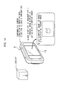
- FIG. 14 is a diagram showing the stereoscopic shooting apparatus displaying a through image according to the fifth embodiment of the present invention.
- FIG. 15 is a flowchart showing a process procedure when a stereoscopic image or a 2D image is shot by the stereoscopic shooting apparatus
- FIG. 16 is a block diagram showing a sixth embodiment of the stereoscopic display apparatus according to the present invention.
- FIG. 17 is a diagram showing the state in which an object (a subject) away in a depth direction is shot by the stereoscopic shooting apparatus
- FIG. 18 is a flowchart showing the sixth embodiment of the present invention.
- FIG. 19 is a diagram showing the state in which a partial image of a left viewpoint image with a large parallax is replaced by a corresponding partial image of a right viewpoint image;
- FIG. 20 is a diagram showing the state of using a button image as a dominant eye judgment image and that dominant eye judgment image is touched;
- FIG. 21 is a diagram showing a display screen when uniaxial slide bar images are used as dominant eye judgment images
- FIG. 22 is a diagram showing a state of using uniaxial-type slide bar images as dominant eye judgment images and that one dominant eye judgment image is touched;
- FIG. 23 is a diagram showing a display screen of a stereoscopic display part when a biaxial-type slide bar image is used as a dominant eye judgment image;
- FIG. 24 is a diagram showing a display screen of a stereoscopic display part when a line drawing representing a rabbit is used as a dominant eye judgment image;
- FIG. 25 is a diagram showing a display screen of the stereoscopic display part when an unfinished picture (an image of a rabbit without ears) is used as a dominant eye judgment image;
- FIG. 26 is a diagram showing the state of adding an image (an image of ears) the dominant eye judgment image displayed on the display screen of the stereoscopic display part lacks;
- FIG. 27 is a flowchart showing a seventh embodiment of the present invention.
- FIG. 28 is a diagram showing a relation between a place thought to have been touched on a stereoscopic image and positions actually touched on left and right viewpoint images.
- FIG. 1 is a block diagram showing a first embodiment of the stereoscopic display apparatus according to the present invention.
- this stereoscopic display apparatus 1 is configured mainly of a memory part 10 , a display control part 12 , a stereoscopic display part 14 , a loudspeaker part 16 , an input/output part 18 , a recording medium recording part 20 , a touch panel 22 , and a dominant eye judging part 24 .
- the memory part 10 includes a flash memory, a RAM, and others, storing a dominant eye judging program according to the present invention, firmware, dominant eye judgement image formed of a left viewpoint image and a right viewpoint image for judging a dominant eye user's dominant eye information, reference coordinates of each dominant eye judgment image, and user's dominant eye information and functions as a memory temporarily storing image data for display to be displayed on the stereoscopic display part 14 .
- the dominant eye judging program and others for use may be those stored in an HDD or a magneto-optical recording medium such as a CD/DVD/BD or the like.
- the display control part 12 is a portion that causes the stereoscopic display part 14 to display images such as a dominant eye judgement image for judging a dominant eye, a stereoscopic image (a 3D image), a dominant-eye-side viewpoint image (a 2D image), a normal 2D image, and others including an image for GUI or the like, and can be a central processing unit (CPU), for example.
- a dominant eye judgement image for judging a dominant eye
- a 3D image a stereoscopic image
- a 2D image dominant-eye-side viewpoint image
- 2D image normal 2D image
- others including an image for GUI or the like
- CPU central processing unit
- the stereoscopic display part 14 is a liquid-crystal monitor capable of displaying two viewpoint images (a left viewpoint image and a right viewpoint image) with a parallax barrier as objective images each having a predetermined directivity. Note that as the stereoscopic display part 14 , a part using a lenticular lens or a part allowing the left viewpoint image and the right viewpoint image to be individually viewed by wearing dedicated eyeglasses such as liquid-crystal shutter eyeglasses can be applied.
- the loudspeaker part 16 generates audio based on audio data at the time of replaying an audio-attached image (a still picture or a moving picture).
- the input/output part 18 is an interface inputting and outputting information such as image data to and from an external device such as a personal computer.
- the recording medium recording part 20 reads and writes image data from and to the removable recording medium 30 such as a memory card.
- the touch panel 22 is provided on a display surface of the stereoscopic display part 14 and, when a user touches an arbitrary position on the touch panel 22 , two-dimensional coordinate data of that touched position is sent to the dominant eye judging part 24 and a stereoscopic touched position coordinate determining part 26 .
- the dominant eye judging part 24 judges a dominant eye of the user touching the touch panel 22 , based on the coordinate data of the touched position obtained from the touch panel 22 at the time of judging a dominant eye. Note that details of this dominant eye judgement are described further below.
- FIG. 2 is a flowchart showing a dominant eye judging process and storage and registration of dominant eye information.
- the dominant eye judging method, dominant eye judging program, and others according to the present invention are described below in accordance with the flowchart shown in FIG. 2 .
- Dominant eye setting and judgement are started. While it is ideal, in practice, to judge a dominant eye in a process of a touch panel operation by the user when the stereoscopic display apparatus 1 is started up or when a start button is operated or date setting is performed, for example, dominant eye judgement may be started by selecting a menu of dominant eye setting and judgement.
- the display control part 12 When dominant eye setting and judgement are started, the display control part 12 first causes the stereoscopic display part 14 to display a screen on which it is selected whether to input information about the dominant eye by the user.
- the procedure makes a transition to step S 14 .
- the procedure makes a transition to step S 16 .
- the display control part 12 causes the stereoscopic display part 14 to display “which is your dominant eye, the right eye or the left eye?”, prompting the user to select the dominant eye.
- information about the selected dominant eye is read and stored in the memory part 10 or the recording medium recording part 30 , and the procedure ends.
- the display control part 12 causes the stereoscopic display part 14 to display a screen on which it is selected whether to use the previous dominant eye judgement result or the stored information about the dominant eye.
- the procedure makes a transition to step S 18 .
- the procedure makes a transition to step S 20 .
- the dominant eye information is read from the memory part 10 or the recording medium 30 , and the procedure ends.
- the display control part 12 causes the stereoscopic display part 14 to display a screen on which it is selected whether a dominant eye judgement is made. When a dominant eye judgement is not made, the procedure makes a transition to step S 22 . When a dominant eye judgement is made, the procedure makes a transition to step S 24 .
- the display control part 12 causes the stereoscopic display part 14 to display a dominant eye judgement image and characters “Please press the cross center.”
- This dominant eye judgement image is a stereoscopic image formed of a left viewpoint image and a right viewpoint image.
- the stereoscopic image is a mark image with a circle having a cross therein.
- the dominant eye judgment image and reference coordinates of each image are stored in the memory part 10 .
- the dominant eye judgment image is not restricted to the one in this embodiment, and can be any as long as the image is an image with a parallax and can specify a place pressed by the user.
- one or plurality of icon images for operation displayed on the stereoscopic display part 14 may be used as a dominant eye judgement image. According to this, while an operation of touching or clicking an icon image or the like is being performed, a dominant eye judgement can be automatically performed inside.
- the dominant eye judging part 24 detects whether the dominant eye judgement image on the screen of the stereoscopic display part 14 has been pressed (whether the touch panel 22 has been touched). If the image has not been pressed for a predetermined time or more (in the case of “No”), the procedure makes a transition to step S 28 . If the image has been pressed (in the case of “Yes”), the procedure makes a transition to step S 30 .
- the dominant eye judging part 24 judges the right eye as the dominant eye and reads the judgement result for storage in the memory part 10 or the recording medium 30 , and the procedure ends.
- the reason for this is that, since people with the right eye as the dominant eye are more than people with the left eye as the dominant eye, the right eye is taken as the dominant eye, thereby reducing an error in judgement as much as possible.
- the dominant eye judging part 24 obtains, via the touch panel 22 , position coordinates where the dominant eye judgement image has been pressed, and judges the user's dominant eye based on these position coordinates and the reference position of each of the left viewpoint image and the right viewpoint image of the dominant eye judgement image.
- a left viewpoint difference DL and a right viewpoint difference DR are calculated as shown in FIG. 4 and [Equation 1] and [Equation 2] below.
- Left viewpoint difference DL
- DL ⁇ square root over (( x 1 ⁇ x 2) 2 +( y 1 ⁇ y 2) 2 ) ⁇ square root over (( x 1 ⁇ x 2) 2 +( y 1 ⁇ y 2) 2 ) ⁇ [Equation 1]
- Right viewpoint difference DR
- DR ⁇ square root over (( x 3 ⁇ x 4) 2 +( y 3 ⁇ y 4)) 2 ) ⁇ square root over (( x 3 ⁇ x 4) 2 +( y 3 ⁇ y 4)) 2 ) ⁇ [Equation 2]
- DL ⁇ DR the left eye is judged as the dominant eye.
- Information about thus judged user's dominant eye is stored in the memory part 10 or the recording medium 30 , and the procedure ends.
- a dominant eye judgement can be made only by touching the dominant eye judgement image displayed on the stereoscopic display part 14 , and the result can be registered.
- FIG. 5 is a block diagram showing a second embodiment of a stereoscopic display apparatus according to the present invention. Note that portions common to those in the first embodiment shown in FIG. 1 are provided with the same reference numerals and are not described in detail herein.
- a stereoscopic display apparatus 2 of the second embodiment is different from that of the first embodiment in that a stereoscopic touched position coordinate determining part 26 is added.
- the stereoscopic touched position coordinate determining part 26 determines position coordinates on the stereoscopic image touched by the user, based on the information about the dominant eye of the user and the coordinate data of the touched position obtained from the touch panel 22 .
- FIG. 6 is a flowchart showing a process procedure of determining position coordinates on a stereoscopic image touched by a user, and description is made below in accordance with the flowchart shown in FIG. 6 .
- Stereoscopic display by the stereoscopic display apparatus 2 is started. Note that, at the start of stereoscopic display, as described above, dominant eye information of the user is assumed to be registered in the memory part 10 or the recording medium 30 .
- the stereoscopic touched position coordinate determining part 26 reads the dominant eye information of the user registered in advance from the memory part 10 or the recording medium 30 .
- the display control part 12 reads the stereoscopic image from the memory part 10 or the recording medium 30 or reads the stereoscopic image from the external device via the input/output part 18 , and causes the stereoscopic display part 14 to display the read stereoscopic image.
- the user touches the touch panel 22 when operating the displayed stereoscopic image, and the stereoscopic touched position coordinate determining part 26 determines whether the user has touched the screen (the touch panel 22 ) of the stereoscopic display part 14 . And, when it is detected that the screen has been touched, the procedure makes a transition to step S 48 .
- Coordinates (x, y) on the touched touch panel 22 are read as coordinates on the dominant-eye-side viewpoint image of the user in the displayed stereoscopic image, and are stored in the memory part 10 .
- the dominant eye is the right eye as shown in FIG. 7
- the touched coordinates (x, y) are dealt as coordinates on the right viewpoint image.
- a deviation disappears or is reduced between a place thought by the user to be touched on the stereoscopic image and a place on the viewpoint image actually detected as a touched position, thereby improving operability of the stereoscopic image by the touch panel 22 .
- the zoom center can be correctly indicated.
- a soft button, various icons, and others are stereoscopically displayed, an erroneous operation of the soft button and others can be prevented.
- FIG. 8 is a block diagram showing a third embodiment of the stereoscopic display apparatus according to the present invention. Note that portions common to those in the first embodiment shown in FIG. 1 are provided with the same reference numerals and are not described in detail herein.
- a stereoscopic display apparatus 3 of the third embodiment is different from that of the first embodiment in that a 3D/2D display mode switching part 28 is added.
- the 3D/2D display mode switching part 28 makes an instruction for switching as to which of the left viewpoint image or the right viewpoint image is to be displayed, based on the user's dominant eye information.
- FIG. 9 is a flowchart showing a process procedure when switching is made from the state of displaying a stereoscopic image (a 3D image) to a 2D image of a left viewpoint image or a right viewpoint image, and description is made below in accordance with the flowchart shown in FIG. 9 .
- Stereoscopic display by the stereoscopic display apparatus 3 is started. Note that the memory part 10 or the recording medium 30 is assumed to have user's dominant eye information registered therein at the start of stereoscopic display.
- the 3D/2D display mode switching part 28 reads the user's dominant eye information registered in advance from the memory part 10 or the recording medium 30 .
- the display control part 12 reads a stereoscopic image from the memory part 10 or the recording medium 30 or reads a stereoscopic image from an external device via the input/output part 18 , and causes the stereoscopic display part 14 to display the read stereoscopic image (a 3D image).
- the user can press a display mode switch button, the touch panel 22 , or the like not shown to make an instruction for switching from the stereoscopic image (the 3D image) to a 2D image of the left viewpoint image or the right viewpoint image.
- the display control part 12 discriminates whether an instruction by the user for switching from the 3D image to the 2D image is present, and causes the procedure to make a transition to step S 54 when an instruction for switching to the 2D image is not present (in the case of “No”) and to make a transition to step S 58 when an instruction for switching to the 2D image is present (in the case of “Yes”).
- the 3D/2D display mode switching part 28 causes the stereoscopic display part 14 to display a user's dominant-eye-side viewpoint image (a 2D image) based on the user's dominant eye information read at step S 52 or provides the display control part 12 with an instruction as to which of the left viewpoint image and the right viewpoint image is to be displayed, and causes the stereoscopic display part 14 to display only the user's dominant-eye-side viewpoint image.
- a 2D image a 2D image
- the dominant eye is the right eye
- the right viewpoint image which is the user's dominant-eye-side image
- the display control part 12 discriminates whether an instruction by the user for switching from the 2D image to the 3D image is present, and causes the procedure to make a transition to step S 58 when an instruction for switching to the 3D image is not present (in the case of “No”) and to make a transition to step S 54 when an instruction for switching to the 2D image is present (in the case of “Yes”).
- FIG. 11 is a flowchart showing a fourth embodiment of the present invention. Note that the structure of a stereoscopic display apparatus is identical to that of the third embodiment shown in FIG. 8 , and is different therefrom only in process details as will be described below. Description is made below in accordance with the flowchart shown in FIG. 11 .
- Stereoscopic display by the stereoscopic display apparatus is started. Note that the memory part 10 or the recording medium 30 is assumed to have user's dominant eye information registered therein at the start of stereoscopic display.
- the 3D/2D display mode switching part 28 reads the user's dominant eye information registered in advance from the memory part 10 or the recording medium 30 .
- a discrimination is made as to whether to set a first mode for 2D display while the touch panel 22 is been continuously touched or a second mode for switching between 3D display and 2D display every time the touch panel 22 is touched.
- This discrimination can be performed by using a discrimination method based on a mode selecting operation by the user every time on a menu screen displayed on the stereoscopic display part 14 or a method of selecting and registering either one of the modes in advance and making a discrimination based on that registered mode.
- the procedure makes a transition to step S 72 .
- the procedure makes a transition to step S 84 .
- the display control part 12 reads a stereoscopic image from the memory part 10 or the recording medium 30 or reads a stereoscopic image from an external device via the input/output part 18 , and causes the stereoscopic display part 14 to display the read stereoscopic image (a 3D image).
- the display control part 12 discriminates whether the user is touching the touch panel 22 while the stereoscopic image (the 3D image) is being displayed. If the touch panel 22 is being touched (in the case of “Yes”), the procedure makes a transition to step S 80 . If not being touched (in the case of “No”), the procedure makes a transition to step S 76 .
- the 3D/2D display mode switching part 28 causes the stereoscopic display part 14 to display a user's dominant-eye-side viewpoint image (a 2D image) based on the user's dominant eye information read at step S 72 or provides the display control part 12 with an instruction as to which of the left viewpoint image and the right viewpoint image is to be displayed, and causes the stereoscopic display part 14 to display only the user's dominant-eye-side viewpoint image.
- a 2D image a 2D image
- the display control part 12 discriminates whether the user is touching the touch panel 22 while the user's dominant-eye-side viewpoint image (the 2D image) is being displayed. If the touch panel 22 is being touched (in the case of “Yes”), the procedure makes a transition to step S 80 . If not being touched (in the case of “No”), the procedure makes a transition to step S 76 .
- a determination “not touched” at step S 82 is made not only when touching is not detected by the touch panel 22 but may be made when touching is not detected for a predetermined period or more. According to this, it is possible to switch to the 3D image during a series of touch panel operations.
- the display control part 12 reads a stereoscopic image from the memory part 10 or the recording medium 30 or reads a stereoscopic image from an external device via the input/output part 18 , and causes the stereoscopic display part 14 to display the read stereoscopic image (a 3D image).
- the display control part 12 discriminates whether the user is touching (clicking) the touch panel 22 while the stereoscopic image (the 3D image) is being displayed. If the touch panel 22 is being clicked (in the case of “Yes”), the procedure makes a transition to step S 88 . If not being clicked (in the case of “No”), the procedure makes a transition to step S 84 .
- the display control part 12 switches display from the stereoscopic image (the 3D image) displayed on the stereoscopic display part 14 to the user's dominant-eye-side viewpoint image (the 2D image).
- the dominant-eye-side right viewpoint image (the 2D image) can be displayed as being switched from the stereoscopic image (the 3D image).
- the display control part 12 discriminates whether the user has touched (clicked) the touch panel 22 while the user's dominant-eye-side viewpoint image (the 2D image) is being displayed. If the touch panel 22 has been clicked (in the case of “Yes”), the procedure makes a transition to step S 84 . If not been clicked (in the case of “No”), the procedure makes a transition to step S 88 .
- the stereoscopic image (the 3D image) and the dominant-eye-side viewpoint image (the 2D image) can be alternately switched for display with one touch (one click) on the touch panel 22 , thereby improving operability.
- FIG. 13 is a block diagram showing an embodiment (a fifth embodiment) of a stereoscopic shooting apparatus according to the present invention. Note that portions common to those in the first embodiment shown in FIG. 1 are provided with the same reference numerals and are not described in detail herein.
- a stereoscopic shooting apparatus 5 shown in FIG. 13 is an apparatus having the stereoscopic display apparatus 1 shown in FIG. 1 , and includes, in addition to the stereoscopic display apparatus 1 shown in FIG. 1 , a stereoscopic shooting part 32 and a 2D through image display viewpoint selecting part 34 .
- the stereoscopic shooting part 32 is formed of, for example, paired left and right shooting parts capable of simultaneously shooting two viewpoint images (a left viewpoint image and a right viewpoint image), and the left viewpoint image and the right viewpoint image shot by this stereoscopic shooting part 32 are subjected to image processing as appropriate and are then recorded on the recording medium 30 .
- the stereoscopic display part 14 is provided, as shown in FIG. 14 , at the back surface of the stereoscopic shooting apparatus 5 , functioning as a device for display at the time of replaying a stereoscopic image and also as a view finder at the time of shooting, displaying a 3D image or a 2D image (a through image) as moving pictures successively shot by the stereoscopic shooting part 32 .
- this stereoscopic shooting apparatus 5 has a 3D shooting mode for shooting a stereoscopic image (a 3D image) and a 2D shooting mode for shooting a 2D image of the left viewpoint image or the right viewpoint image, and includes a shooting mode switching part for selecting from these shooting modes.
- the 2D through image display viewpoint selecting part 34 makes an instruction for switching as to which of through images of viewpoint images, that is, the left viewpoint image or the right viewpoint image, is to be displayed at the time of switching from a through image of the stereoscopic image (the 3D image) to the through image of the 2D image of the left viewpoint image or the right viewpoint image.
- FIG. 15 is a flowchart showing a process procedure when a stereoscopic image or a 2D image is shot by the stereoscopic shooting apparatus 5 described above. Description is made below in accordance with the flowchart shown in FIG. 15 .
- the 2D through image display viewpoint selecting part 34 reads the user's dominant eye information registered in advance from the memory part 10 or the recording medium 30 .
- the stereoscopic shooting apparatus 5 discriminates whether a shooting mode switching button for switching a 3D shooting mode to a 2D shooting mode has been pressed. If the button for switching to the 2D shooting mode has been pressed (in the case of “Yes”), the apparatus causes the procedure to make a transition to step S 106 . If not been pressed (in the case of “No”), the apparatus causes the procedure to make a transition to step S 108 .
- the 2D through image display viewpoint selecting part 34 causes the stereoscopic shooting part 32 to shoot a user's dominant-eye-side viewpoint image (a 2D image) based on the user's dominant eye information read at step S 102 , and causes the stereoscopic display part 14 to display its through image.
- the right viewpoint image (a 2D image) is displayed on the stereoscopic display part 14 as a through image.
- the 2D image is shot, and recorded on the recording medium 30 .
- the stereoscopic shooting apparatus 5 successively shots stereoscopic images (a left and right two viewpoint images), and causes the stereoscopic display part 14 to display the shot stereoscopic image (the 3D image) as a thorough image.
- the shutter release button is pressed, the stereoscopic image (a 2D image) is shot, and recorded in the recording medium 30 .
- the user's dominant-eye-side viewpoint image (the 2D image) can be displayed on the stereoscopic display part 14 when a through image is displayed at the time of 2D shooting mode, thereby improving ease of shooting a 2D image. Also, since the user does not feel uncomfortable when viewing a thing with the dominant eye, the user is less prone to be tired, and a larger amount of information can be advantageously obtained.
- the present method is not restricted to a shooting mode of a still picture but also can be applied to display at the time of switching between the 3D image and the 2D image at the time of moving-picture shooting mode.
- FIG. 16 is a block diagram showing a sixth embodiment of the stereoscopic display apparatus according to the present invention. Note that portions common to those in the first embodiment shown in FIG. 1 are provided with the same reference numerals and are not described in detail herein.
- a stereoscopic display apparatus 6 of the sixth embodiment is different from that of the first embodiment in that an image replacing part 36 is added.
- a stereoscopic image of that subject portion is replaced by the dominant-eye-side viewpoint image, thereby improving quality of the stereoscopic image.
- the image replacing part 36 shown in FIG. 16 has a parallax amount detecting part detecting left and right parallax amounts of the stereoscopic image (the 3D image) and a region extracting part extracting a subject region exceeding a parallax amount set in advance (a specified number of pixels) from among the detected parallax amounts or a parallax amount of a region appearing doubled, the region specified by the user.
- a stereoscopic image of the extracted subject region is replaced only by the dominant-eye-side viewpoint image corresponding to the user's dominant eye information registered in advance from the memory part 10 or the recording medium 30 .
- FIG. 18 is a flowchart showing the sixth embodiment of the present invention, and description is made below according to the flowchart shown in FIG. 18 .
- Stereoscopic display by the stereoscopic display apparatus 6 is started. Note that the memory part 10 or the recording medium 30 is assumed to have user's dominant eye information registered therein at the start of stereoscopic display.
- the image replacing part 36 reads user's dominant eye information registered in advance from the memory part 10 or the recording medium 30 . [Step S 114 ]
- the display control part 12 causes the stereoscopic display part 14 to display a screen accepting an instruction input as to whether a replacement portion is automatically selected or the mode is a replacement mode (a replacement mode in which a replacement portion is manually specified) to prompt a input of the user.
- a replacement mode a replacement mode in which a replacement portion is manually specified
- the procedure makes a transition to step S 116 .
- the replacement mode in which a replacement portion is manually specified is selected (in the case of “No”), the procedure makes a transition to step S 122 .
- the region extracting part of the image replacing part 36 finds a place having a parallax amount equal to a parallax amount set in advance from the stereoscopic image.
- a parallax amount set in advance for example, ten pixels may be set by default, and this default value may be arbitrarily set by the user. This is because the merge limit allowing stereoscopic viewing varies depending on the user.
- the image replacing part 36 Based on the user's dominant eye information read at step S 112 , the image replacing part 36 replaces the viewpoint image not on a user's dominant eye side at the found place by the user's dominant-eye-side viewpoint image (the 2D image).
- the display control part 12 causes the stereoscopic display part 14 to display the stereoscopic image after replacement at step S 118 . With this, no place appearing doubled is present, thereby improving the quality of the stereoscopic image.
- the present method is based on an idea “a 2D image is better than an image appearing doubled.”
- the stereoscopic display apparatus 6 accepts an input of a range appearing doubled upon an instruction from the touch panel 22 by the user.
- the image replacing part 36 replaces the viewpoint image not on a user's dominant eye side of the input place by the user's dominant-eye-side viewpoint image (the 2D image). Note that when the user specifies a range appearing doubled on the touch panel 22 , a range having the same parallax as that of the specified range may be extracted, and the viewpoint image not on a user's dominant eye side of this extracted range may be replaced by the user's dominant-eye-side viewpoint image (the 2D image).
- the display control part 12 causes the stereoscopic display part 14 to display stereoscopic pixels after replacement at step S 124 . With this, no place specified in range by the user as appearing doubled is present, thereby improving the quality of the stereoscopic image.
- the touch panel 22 on the stereoscopic display apparatus 6 is used as a coordinate input device for the user arbitrarily inputting position coordinates
- this is not meant to be restrictive, and others may be applied as a coordinate input device, such as the one in which a cursor is 2D-displayed on the stereoscopic display device 6 and this cursor is moved by using a cross key or the like and also an OK button is pressed to input position coordinates, or a spatial sensor detecting a fingertip position of the user.
- FIG. 20 is a diagram showing a dominant eye judgement image and the state of touching the dominant eye judgment image, and showing a first modification example in which a button image for operation is used in place of the mark image with a circle having a cross therein shown in FIG. 3 .
- an image representing a button for operation such as a start button or a login button is displayed on the stereoscopic display part 14 as a dominant eye judgment image.
- This button image is configured of a left viewpoint image and a right viewpoint image having a predetermined parallax, and has reference coordinates (center coordinates of the button image) of each image.
- the display control part 12 causes the stereoscopic display part 14 to display the button image as the dominant eye judgment image and characters “Please press the button.” Note that in the case of a button image that is inevitably pressed, such as a start button or a login button, it is not required to display characters “Please press the button”, and only a button name or the like is enough to be displayed.
- the dominant eye judging part 24 obtains position coordinates of the pressed button image via the touch panel 22 , and judges the user's dominant eye based on these position coordinates and a reference position of each of the left viewpoint image and the right viewpoint image of the button image.
- This dominant eye judging method can be performed in a manner similar to that of the method described based on FIG. 4 , [Equation 1], and [Equation 2].
- a final dominant eye judgment may be made by means of majority decision regarding the results of dominant eye judgments made by touch operations on a plurality of button images (either same or different types of button images may be used).
- FIG. 21 and FIG. 22 are diagrams showing a second modification example of the dominant eye judgement image, FIG. 21 showing a display screen of the stereoscopic display part 14 and FIG. 22 showing the state of touching the dominant eye judgment image displayed on the display screen.
- images representing five uniaxial-type slide bars are displayed on the stereoscopic display part 14 as the dominant eye judgment images.
- These slide bar images are formed of slide bar images for adjusting the parallax amount, brightness, contrast, white balance, and sound volume of the stereoscopic image, and each slide bar image is configured of a left viewpoint image and a right viewpoint image having a predetermined parallax and also has reference coordinates (center coordinates of a knob in each slide bar image) of each image.
- the display control part 12 causes the stereoscopic display part 14 to display the slide bar images described above as the dominant eye judgment images and characters “Please make various adjustments.”
- the dominant eye judging part 24 obtains, via the touch panel 22 , position coordinates of the first touched knob of the slide bar image, and judges the user's dominant eye based on these position coordinates and the position of the knob in the slide bar image (a reference position of each of the left viewpoint image and the right viewpoint image of the knob before touching).
- This dominant eye judging method can be performed in a manner similar to that of the method described based on FIG. 4 , [Equation 1], and [Equation 2].
- a final dominant eye judgment may be made by means of majority decision regarding the results of dominant eye judgments made by the respective touch operations.
- FIG. 23 is a diagram showing a third modification example of the dominant eye judgement image, showing a biaxial-type slide bar image.
- an image representing a biaxial-type slide bar (a slide bar image) is displayed on the stereoscopic display part 14 as the dominant eye judgment image.
- This slide bar image is to adjust contrast of the stereoscopic image with the position of a knob in a horizontal direction and to adjust brightness of the stereoscopic image with the position thereof in a vertical direction, is configured of a left viewpoint image and a right viewpoint image having a predetermined parallax, and has reference coordinates (center coordinates of the knob in the slide bar image) of each image.
- the dominant eye judging part 24 obtains, via the touch panel 22 , two-dimensional position coordinates of the first touched knob of the slide bar image, and judges the user's dominant eye based on these position coordinates and the position of the knob in the slide bar image (a reference position of each of the left viewpoint image and the right viewpoint image of the knob before touching).
- This dominant eye judging method can be performed in a manner similar to that of the method described based on FIG. 4 , [Equation 1], and [Equation 2].
- a stereoscopically viewable joy stick image may be used in place of the biaxial-type slide bar image of the third modification example described above.
- FIG. 24 is a diagram showing a fourth modification example of the dominant eye judgment image, showing a line drawing representing a rabbit in this example.
- a stereoscopically viewable line drawing is displayed on the stereoscopic display part 14 as the dominant eye judgment image.
- This line drawing is for the user to trace its contour, is configured of a left viewpoint image and a right viewpoint image having a predetermined parallax, and has coordinates of a contour line in each image.
- the dominant eye judging part 24 obtains coordinates of the traced track via the touch panel 22 , and judges the user's dominant eye based on the coordinates of the traced track and coordinates of the counter line of the line drawing (coordinates of the contour line of each of the left viewpoint image and the right viewpoint image).
- this dominant eye judging method an average distance of shortest distances between the coordinates of the traced track and the coordinates of the contour line of the left viewpoint image of the line drawing and an average distance of shortest distances between the coordinates of the traced track and the coordinates of the contour line of the right viewpoint image of the line drawing are found, and the user's dominant eye is judged depending on one of the average distances that is smaller (that is, whether the traced track is near the line drawing of the left viewpoint image or the line drawing of the right viewpoint image).
- a simple graphic is preferable as the line drawing, such as an easily-traceable picture or circle. Also, a user's dominant eye judgment can be performed without tracing the whole contour line of the line drawing.
- FIG. 25 and FIG. 26 are diagrams showing a fifth modification example of the dominant eye judgement image, FIG. 25 showing a display screen of the stereoscopic display part 14 and FIG. 26 showing the state of adding an image the dominant eye judgement image displayed on the display screen lacks.
- an unfinished picture or graphic (an image of a rabbit without ears in FIG. 25 ) is displayed on the stereoscopic display part 14 as the dominant eye judgment image.
- This image of the rabbit without ears is for the user to draw a lacking part (ears), is configured of a left viewpoint image and a right viewpoint image having a predetermined parallax, and has coordinates of a contour line of a head part (a portion where ears are to be drawn) in each image.
- the display control part 12 causes the stereoscopic display part 14 to display the image of the rabbit without ears as the dominant eye judgment image and characters “Please draw and add ears to the rabbit.”
- the display control part 12 causes the stereoscopic display part 14 to display the drawn ears of the rabbit in 2D display.
- the dominant eye judging part 24 obtains coordinates of the drawn track of the ears of the rabbit (in particular, a base portion of the ears) via the touch panel 22 , and judges the user's dominant eye based on the coordinates of the drawn ears of the rabbit and coordinates of the contour lines of the left viewpoint image and the right viewpoint image of the head part of the rabbit.
- the user's dominant eye is judged depending on whether the base portion of the ears of the rabbit drawn as shown in FIG. 26 matches (similar to) the contour line of the left viewpoint image of the head part of the rabbit or matches (similar to) the contour line of the right viewpoint image thereof.
- an image of ears of the rabbit may be prepared in advance, and this part image may be dragged to be attached to the head part of the rabbit.
- the unfinished picture is not restricted to a picture of a rabbit without ears, and any picture can be used.
- the unfinished picture is not restricted to a picture, and a graphic (for example, a polygon without one side) may be used.
- discrimination of the dominant eye can be automatically made on a device side while the user is enjoying drawing, and the result can be registered.
- FIG. 27 is a flowchart showing a seventh embodiment of the present invention, and description is made below in accordance with the flowchart shown in FIG. 27 .
- Dominant eye setting and judgment by a stereoscopic display apparatus 6 are started.
- the display control part 12 When dominant eye setting and judgement are started, the display control part 12 (refer to FIG. 1 ) first causes the stereoscopic display part 14 to display a menu for selecting a dominant eye judging method, thereby prompting the user to select a desired dominant eye judging method.
- the menu for selecting a dominant eye judging method the dominant eye judging method using the button image of FIG. 20 , the dominant eye judging method using the slide bar images of FIG. 21 , the dominant eye judging method using the unfinished picture (the picture of the rabbit without ears of FIG. 25 ), a default dominant eye judging method (for example, the dominant eye judging method using the dominant eye judgment image shown in FIG. 3 ), and others are presented, and any can be selected as appropriate.
- the procedure makes a transition to the process of that default dominant eye judging method. Also, when a dominant eye judgment is not made, the procedure ends without performing a dominant eye judgment.
- the display control part 12 causes the stereoscopic display part 14 to display the button image as the dominant eye judgment image and characters “Please press the button.”
- the dominant eye judging part 24 obtains position coordinates of the pressed button image via the touch panel 22 , makes a user's dominant eye judgment depending on whether these position coordinates are near the reference position of the left viewpoint image of the button image or the reference position of the right viewpoint image thereof, stores the dominant eye judgment result, and ends the procedure.
- the display control part 12 causes the stereoscopic display part 14 to display the slide bar images as the dominant eye judgment images and characters “Please make various adjustments.”
- the dominant eye judging part 24 obtains first touched position coordinates via the touch panel 22 , makes a user's dominant eye judgment depending on whether these position coordinates represent a position before the operation of the knob of the slide bar image and are near the position of the knob of the left viewpoint image or near the position of the knob of the right viewpoint image thereof, stores the dominant eye judgment result, and ends the procedure.
- the display control part 12 causes the stereoscopic display part 14 to display the picture of the rabbit without ears as the dominant eye judgment image and characters “Please draw and add ears to the rabbit.”
- the dominant eye judging part 24 obtains coordinates of the base portion of the drawn and added ears of the rabbit via the touch panel 22 , makes a dominant eye judgment depending on whether the coordinates of the base portion of the ears represent coordinates of the contour line of the head part of the rabbit without ears and are near coordinates of the contour line of the head part of the left viewpoint image or near coordinates of the contour line of the head part of the right viewpoint image thereof, stores the dominant eye judgment result, and ends the procedure.
Landscapes
- Engineering & Computer Science (AREA)
- General Engineering & Computer Science (AREA)
- Theoretical Computer Science (AREA)
- Multimedia (AREA)
- Signal Processing (AREA)
- Human Computer Interaction (AREA)
- Physics & Mathematics (AREA)
- General Physics & Mathematics (AREA)
- Testing, Inspecting, Measuring Of Stereoscopic Televisions And Televisions (AREA)
- Position Input By Displaying (AREA)
- Controls And Circuits For Display Device (AREA)
- User Interface Of Digital Computer (AREA)
Abstract
Description
- PTL 1: Japanese Patent Application Laid-Open No. 10-105735
- PTL 2: Japanese Patent Application Laid-Open No. 2004-280496
- PTL 3: Japanese Patent Application Laid-Open No. 2006-293909
Left viewpoint difference DL=|((1) pressed coordinates of the left viewpoint image−((2) cross center of the left viewpoint image)|
DL=√{square root over ((x1−x2)2+(y1−y2)2)}{square root over ((x1−x2)2+(y1−y2)2)} [Equation 1]
Right viewpoint difference DR=|((1) pressed coordinates of the right viewpoint image−((2) cross center of the right viewpoint image)|
DR=√{square root over ((x3−x4)2+(y3−y4))2)}{square root over ((x3−x4)2+(y3−y4))2)} [Equation 2]
Claims (16)
Applications Claiming Priority (5)
| Application Number | Priority Date | Filing Date | Title |
|---|---|---|---|
| JP2010-062869 | 2010-03-18 | ||
| JP2010062869 | 2010-03-18 | ||
| JP2010-147509 | 2010-06-29 | ||
| JP2010147509 | 2010-06-29 | ||
| PCT/JP2010/069275 WO2011114567A1 (en) | 2010-03-18 | 2010-10-29 | 3d display device and 3d imaging device, dominant eye determination method and dominant eye determination program using same, and recording medium |
Publications (2)
| Publication Number | Publication Date |
|---|---|
| US20120320047A1 US20120320047A1 (en) | 2012-12-20 |
| US9164621B2 true US9164621B2 (en) | 2015-10-20 |
Family
ID=44648686
Family Applications (1)
| Application Number | Title | Priority Date | Filing Date |
|---|---|---|---|
| US13/581,617 Expired - Fee Related US9164621B2 (en) | 2010-03-18 | 2010-10-29 | Stereoscopic display apparatus and stereoscopic shooting apparatus, dominant eye judging method and dominant eye judging program for use therein, and recording medium |
Country Status (4)
| Country | Link |
|---|---|
| US (1) | US9164621B2 (en) |
| JP (1) | JP5450791B2 (en) |
| CN (1) | CN102812420B (en) |
| WO (1) | WO2011114567A1 (en) |
Cited By (1)
| Publication number | Priority date | Publication date | Assignee | Title |
|---|---|---|---|---|
| US20140204014A1 (en) * | 2012-03-30 | 2014-07-24 | Sony Mobile Communications Ab | Optimizing selection of a media object type in which to present content to a user of a device |
Families Citing this family (20)
| Publication number | Priority date | Publication date | Assignee | Title |
|---|---|---|---|---|
| JP5073013B2 (en) | 2010-06-11 | 2012-11-14 | 任天堂株式会社 | Display control program, display control device, display control method, and display control system |
| CN102971692B (en) * | 2010-06-29 | 2016-06-08 | 富士胶片株式会社 | Three-dimensional display apparatus, 3-D view capture device and instruction defining method |
| KR101783259B1 (en) * | 2010-12-31 | 2017-10-10 | 삼성디스플레이 주식회사 | Method for compensating data, compensating apparatus for performing the method and display device having the compensating apparatus |
| KR20130008334A (en) * | 2011-07-12 | 2013-01-22 | 삼성전자주식회사 | Vergence control method for stereo-scopic image control and portable device supporting the same |
| JP2013073449A (en) * | 2011-09-28 | 2013-04-22 | Fujifilm Corp | Stereoscopic image display device having touch panel function, and touch panel |
| WO2013077338A1 (en) * | 2011-11-21 | 2013-05-30 | 株式会社ニコン | Display device, and display control program |
| EP2801198B1 (en) * | 2012-01-04 | 2023-10-11 | InterDigital Madison Patent Holdings, SAS | Processing 3d image sequences |
| US8884928B1 (en) * | 2012-01-26 | 2014-11-11 | Amazon Technologies, Inc. | Correcting for parallax in electronic displays |
| JP5496425B2 (en) * | 2012-02-07 | 2014-05-21 | オリンパス株式会社 | Display device |
| JP6309185B2 (en) * | 2012-08-07 | 2018-04-11 | 任天堂株式会社 | Image display program, image display apparatus, image display system, and image display method |
| US9189095B2 (en) * | 2013-06-06 | 2015-11-17 | Microsoft Technology Licensing, Llc | Calibrating eye tracking system by touch input |
| CN105593787B (en) | 2013-06-27 | 2019-07-05 | 视力移动科技公司 | The system and method for being pointing directly at detection for being interacted with digital device |
| WO2015179539A1 (en) * | 2014-05-20 | 2015-11-26 | The Schepens Eye Research Institute, Inc. | Quantification of inter-ocular suppression in binocular vision impairment |
| CN104378621A (en) * | 2014-11-25 | 2015-02-25 | 深圳超多维光电子有限公司 | Processing method and device for three-dimensional scene |
| CN106265006B (en) * | 2016-07-29 | 2019-05-17 | 维沃移动通信有限公司 | A kind of control method and mobile terminal of the apparatus for correcting of dominant eye |
| JP7356995B2 (en) * | 2018-03-14 | 2023-10-05 | マジック リープ, インコーポレイテッド | Display system and method for clipping content and increasing viewing comfort |
| JP7146585B2 (en) * | 2018-11-13 | 2022-10-04 | 本田技研工業株式会社 | Line-of-sight detection device, program, and line-of-sight detection method |
| JP7178888B2 (en) * | 2018-12-03 | 2022-11-28 | ルネサスエレクトロニクス株式会社 | Information input device |
| JP2021131490A (en) * | 2020-02-20 | 2021-09-09 | キヤノン株式会社 | Information processing device, information processing method, and program |
| IT202000022120A1 (en) * | 2020-09-18 | 2020-12-18 | Univ Degli Studi Di Trento | Ocular dominance quantification system and procedure |
Citations (27)
| Publication number | Priority date | Publication date | Assignee | Title |
|---|---|---|---|---|
| JPH10105735A (en) | 1996-09-30 | 1998-04-24 | Terumo Corp | Input device and picture display system |
| US5875018A (en) * | 1994-05-20 | 1999-02-23 | Lamprecht; Juergen | Process and device for the projection of image information for persons with visual impairment caused by deviation of the position of their optical axis |
| EP1021049A2 (en) | 1999-01-14 | 2000-07-19 | Sony Corporation | Stereoscopic video display method and apparatus |
| US6584219B1 (en) * | 1997-09-18 | 2003-06-24 | Sanyo Electric Co., Ltd. | 2D/3D image conversion system |
| JP2004280496A (en) | 2003-03-17 | 2004-10-07 | Kyocera Mita Corp | Operation panel device |
| JP2004362218A (en) | 2003-06-04 | 2004-12-24 | Canon Inc | Three-dimensional object operating method |
| US20060098282A1 (en) * | 2002-07-02 | 2006-05-11 | Mccart John R | Visual media |
| JP2006293909A (en) | 2005-04-14 | 2006-10-26 | Denso Corp | Driver sight line direction detecting device |
| EP2046020A1 (en) | 2007-10-05 | 2009-04-08 | Fujifilm Corporation | Image recording apparatus and image recording method |
| US20090237803A1 (en) | 2008-03-21 | 2009-09-24 | Kabushiki Kaisha Toshiba | Display device, display method and head-up display |
| US20110032338A1 (en) * | 2009-08-06 | 2011-02-10 | Qualcomm Incorporated | Encapsulating three-dimensional video data in accordance with transport protocols |
| US20110032329A1 (en) * | 2009-08-06 | 2011-02-10 | Qualcomm Incorporated | Transforming video data in accordance with three dimensional input formats |
| US20110032328A1 (en) * | 2009-08-06 | 2011-02-10 | Qualcomm Incorporated | Transforming video data in accordance with human visual system feedback metrics |
| US20110228049A1 (en) * | 2010-03-12 | 2011-09-22 | Yuri Kazakevich | Stereoscopic visualization system |
| US8057036B2 (en) * | 2007-10-23 | 2011-11-15 | Mcgill University | Binocular vision assessment and/or therapy |
| US20110298702A1 (en) * | 2009-12-14 | 2011-12-08 | Kotaro Sakata | User interface device and input method |
| US20120019527A1 (en) * | 2010-07-26 | 2012-01-26 | Olympus Imaging Corp. | Display apparatus, display method, and computer-readable recording medium |
| US8284235B2 (en) * | 2009-09-28 | 2012-10-09 | Sharp Laboratories Of America, Inc. | Reduction of viewer discomfort for stereoscopic images |
| US20130120362A1 (en) * | 2011-11-16 | 2013-05-16 | Christie Digital Systems Usa, Inc. | Collimated stereo display system |
| US20130182086A1 (en) * | 2013-03-11 | 2013-07-18 | Allan Thomas Evans | Apparatus for enhancing stereoscopic images |
| US20130258463A1 (en) * | 2013-03-11 | 2013-10-03 | Allan Thomas Evans | System, method, and apparatus for enhancing stereoscopic images |
| US8558875B2 (en) * | 2008-09-29 | 2013-10-15 | Panasonic Corporation | Video signal processing device |
| US20140063083A1 (en) * | 2012-09-03 | 2014-03-06 | Samsung Display Co., Ltd. | Display apparatus and method for enabling perception of three-dimensional images |
| US20140184494A1 (en) * | 2012-12-31 | 2014-07-03 | Giedrius Tomas Burachas | User Centric Interface for Interaction with Visual Display that Recognizes User Intentions |
| US20140200079A1 (en) * | 2013-01-16 | 2014-07-17 | Elwha Llc | Systems and methods for differentiating between dominant and weak eyes in 3d display technology |
| US20140253698A1 (en) * | 2013-03-11 | 2014-09-11 | Allan Thomas Evans | System, apparatus, and method for enhancing stereoscopic images |
| US8880336B2 (en) * | 2012-06-05 | 2014-11-04 | Apple Inc. | 3D navigation |
Family Cites Families (1)
| Publication number | Priority date | Publication date | Assignee | Title |
|---|---|---|---|---|
| JP4657331B2 (en) * | 2008-08-27 | 2011-03-23 | 富士フイルム株式会社 | Pointed position setting device, method and program for three-dimensional display |
-
2010
- 2010-10-29 CN CN201080065556.9A patent/CN102812420B/en not_active Expired - Fee Related
- 2010-10-29 WO PCT/JP2010/069275 patent/WO2011114567A1/en active Application Filing
- 2010-10-29 JP JP2012505443A patent/JP5450791B2/en not_active Expired - Fee Related
- 2010-10-29 US US13/581,617 patent/US9164621B2/en not_active Expired - Fee Related
Patent Citations (33)
| Publication number | Priority date | Publication date | Assignee | Title |
|---|---|---|---|---|
| US5875018A (en) * | 1994-05-20 | 1999-02-23 | Lamprecht; Juergen | Process and device for the projection of image information for persons with visual impairment caused by deviation of the position of their optical axis |
| JPH10105735A (en) | 1996-09-30 | 1998-04-24 | Terumo Corp | Input device and picture display system |
| US6584219B1 (en) * | 1997-09-18 | 2003-06-24 | Sanyo Electric Co., Ltd. | 2D/3D image conversion system |
| EP1021049A2 (en) | 1999-01-14 | 2000-07-19 | Sony Corporation | Stereoscopic video display method and apparatus |
| JP2000209614A (en) | 1999-01-14 | 2000-07-28 | Sony Corp | Stereoscopic video system |
| US6466255B1 (en) | 1999-01-14 | 2002-10-15 | Sony Corporation | Stereoscopic video display method and apparatus, stereoscopic video system, and stereoscopic video forming method |
| US20060098282A1 (en) * | 2002-07-02 | 2006-05-11 | Mccart John R | Visual media |
| JP2004280496A (en) | 2003-03-17 | 2004-10-07 | Kyocera Mita Corp | Operation panel device |
| JP2004362218A (en) | 2003-06-04 | 2004-12-24 | Canon Inc | Three-dimensional object operating method |
| JP2006293909A (en) | 2005-04-14 | 2006-10-26 | Denso Corp | Driver sight line direction detecting device |
| EP2046020A1 (en) | 2007-10-05 | 2009-04-08 | Fujifilm Corporation | Image recording apparatus and image recording method |
| US20090091654A1 (en) | 2007-10-05 | 2009-04-09 | Fujifilm Corporation | Image recording apparatus and image recording method |
| JP2009094726A (en) | 2007-10-05 | 2009-04-30 | Fujifilm Corp | Image recording apparatus and image recording method |
| US8057036B2 (en) * | 2007-10-23 | 2011-11-15 | Mcgill University | Binocular vision assessment and/or therapy |
| US20090237803A1 (en) | 2008-03-21 | 2009-09-24 | Kabushiki Kaisha Toshiba | Display device, display method and head-up display |
| JP2009229752A (en) | 2008-03-21 | 2009-10-08 | Toshiba Corp | Display device, display method and headup display |
| US7830607B2 (en) * | 2008-03-21 | 2010-11-09 | Kabushiki Kaisha Toshiba | Display device, display method and head-up display |
| US8558875B2 (en) * | 2008-09-29 | 2013-10-15 | Panasonic Corporation | Video signal processing device |
| US20110032338A1 (en) * | 2009-08-06 | 2011-02-10 | Qualcomm Incorporated | Encapsulating three-dimensional video data in accordance with transport protocols |
| US20110032329A1 (en) * | 2009-08-06 | 2011-02-10 | Qualcomm Incorporated | Transforming video data in accordance with three dimensional input formats |
| US20110032328A1 (en) * | 2009-08-06 | 2011-02-10 | Qualcomm Incorporated | Transforming video data in accordance with human visual system feedback metrics |
| US8284235B2 (en) * | 2009-09-28 | 2012-10-09 | Sharp Laboratories Of America, Inc. | Reduction of viewer discomfort for stereoscopic images |
| US20110298702A1 (en) * | 2009-12-14 | 2011-12-08 | Kotaro Sakata | User interface device and input method |
| US20110228049A1 (en) * | 2010-03-12 | 2011-09-22 | Yuri Kazakevich | Stereoscopic visualization system |
| US20120019527A1 (en) * | 2010-07-26 | 2012-01-26 | Olympus Imaging Corp. | Display apparatus, display method, and computer-readable recording medium |
| US20130120362A1 (en) * | 2011-11-16 | 2013-05-16 | Christie Digital Systems Usa, Inc. | Collimated stereo display system |
| US8880336B2 (en) * | 2012-06-05 | 2014-11-04 | Apple Inc. | 3D navigation |
| US20140063083A1 (en) * | 2012-09-03 | 2014-03-06 | Samsung Display Co., Ltd. | Display apparatus and method for enabling perception of three-dimensional images |
| US20140184494A1 (en) * | 2012-12-31 | 2014-07-03 | Giedrius Tomas Burachas | User Centric Interface for Interaction with Visual Display that Recognizes User Intentions |
| US20140200079A1 (en) * | 2013-01-16 | 2014-07-17 | Elwha Llc | Systems and methods for differentiating between dominant and weak eyes in 3d display technology |
| US20130258463A1 (en) * | 2013-03-11 | 2013-10-03 | Allan Thomas Evans | System, method, and apparatus for enhancing stereoscopic images |
| US20140253698A1 (en) * | 2013-03-11 | 2014-09-11 | Allan Thomas Evans | System, apparatus, and method for enhancing stereoscopic images |
| US20130182086A1 (en) * | 2013-03-11 | 2013-07-18 | Allan Thomas Evans | Apparatus for enhancing stereoscopic images |
Non-Patent Citations (6)
| Title |
|---|
| Chinese Office Action and Search Report, dated Dec. 2, 2014, for Chinese Application No. 201080065556.9, with English translation. |
| Forms PCT/IB/326, PCT/IB/373, and PCT/ISA/237, mailed Sep. 27, 2012 for International Application No. PCT/JP2010/069275. |
| Forms PCT/IB/373 and PCT/ISA/237, issued Oct. 23, 2012, for International Application No. PCT/JP2010/069275. |
| International Search Report issued in PCT/JP2010/069275, mailed on Dec. 28, 2010. |
| Japanese Office Action for Japanese Application No. 2012-505443, dated Sep. 26, 2013, with partial English translation. |
| Written Opinion of the International Searching Authority issued in PCT/JP2010/069275, mailed on Dec. 28, 2010. |
Cited By (1)
| Publication number | Priority date | Publication date | Assignee | Title |
|---|---|---|---|---|
| US20140204014A1 (en) * | 2012-03-30 | 2014-07-24 | Sony Mobile Communications Ab | Optimizing selection of a media object type in which to present content to a user of a device |
Also Published As
| Publication number | Publication date |
|---|---|
| CN102812420B (en) | 2016-01-20 |
| CN102812420A (en) | 2012-12-05 |
| JPWO2011114567A1 (en) | 2013-06-27 |
| US20120320047A1 (en) | 2012-12-20 |
| WO2011114567A1 (en) | 2011-09-22 |
| JP5450791B2 (en) | 2014-03-26 |
Similar Documents
| Publication | Publication Date | Title |
|---|---|---|
| US9164621B2 (en) | Stereoscopic display apparatus and stereoscopic shooting apparatus, dominant eye judging method and dominant eye judging program for use therein, and recording medium | |
| TWI463392B (en) | Image processing device, image processing method and program cross-reference to related application | |
| JP5745241B2 (en) | Information processing program, information processing apparatus, information processing system, and information processing method | |
| JP5689707B2 (en) | Display control program, display control device, display control system, and display control method | |
| US8350896B2 (en) | Terminal apparatus, display control method, and display control program | |
| JP4657331B2 (en) | Pointed position setting device, method and program for three-dimensional display | |
| JP6569496B2 (en) | Input device, input method, and program | |
| US20120075424A1 (en) | Computer-readable storage medium having image processing program stored therein, image processing apparatus, image processing system, and image processing method | |
| JP5263355B2 (en) | Image display device and imaging device | |
| CN103608761B (en) | Input equipment, input method and recording medium | |
| CN106873886B (en) | Control method and device for stereoscopic display and electronic equipment | |
| US9727229B2 (en) | Stereoscopic display device, method for accepting instruction, and non-transitory computer-readable medium for recording program | |
| CN112616048B (en) | AR glasses, display method and system thereof, image processing method and device | |
| JPWO2012002057A1 (en) | Stereoscopic display device, stereoscopic imaging device, and instruction determination method | |
| JP2013156889A (en) | Movement control device, control method for movement control device, and program | |
| JP6805524B2 (en) | Input device, input program, and input method | |
| JP2012208723A (en) | Game device, method for controlling game device, and program | |
| US9591296B2 (en) | Image processing device, image processing method, and image processing program that links three-dimensional protrusion intensity setting value and user interface spatial recognition sensitivity setting value | |
| JP5770018B2 (en) | Display control program, display control apparatus, display control method, and display control system | |
| US9218104B2 (en) | Image processing device, image processing method, and computer program product | |
| JP2012130499A (en) | Game device, game program, game system, and game method | |
| JP5140719B2 (en) | Pointed position setting device, method and program for three-dimensional display | |
| KR20230027950A (en) | Virtual reality system with touch user interface |
Legal Events
| Date | Code | Title | Description |
|---|---|---|---|
| AS | Assignment |
Owner name: FUJIFILM CORPORATION, JAPAN Free format text: ASSIGNMENT OF ASSIGNORS INTEREST;ASSIGNORS:YANAGITA, SATOSHI;MISAWA, ATSUSHI;REEL/FRAME:028873/0681 Effective date: 20120726 |
|
| STCF | Information on status: patent grant |
Free format text: PATENTED CASE |
|
| MAFP | Maintenance fee payment |
Free format text: PAYMENT OF MAINTENANCE FEE, 4TH YEAR, LARGE ENTITY (ORIGINAL EVENT CODE: M1551); ENTITY STATUS OF PATENT OWNER: LARGE ENTITY Year of fee payment: 4 |
|
| FEPP | Fee payment procedure |
Free format text: MAINTENANCE FEE REMINDER MAILED (ORIGINAL EVENT CODE: REM.); ENTITY STATUS OF PATENT OWNER: LARGE ENTITY |
|
| LAPS | Lapse for failure to pay maintenance fees |
Free format text: PATENT EXPIRED FOR FAILURE TO PAY MAINTENANCE FEES (ORIGINAL EVENT CODE: EXP.); ENTITY STATUS OF PATENT OWNER: LARGE ENTITY |
|
| STCH | Information on status: patent discontinuation |
Free format text: PATENT EXPIRED DUE TO NONPAYMENT OF MAINTENANCE FEES UNDER 37 CFR 1.362 |
|
| FP | Lapsed due to failure to pay maintenance fee |
Effective date: 20231020 |