US9170624B2 - User level control of power management policies - Google Patents

User level control of power management policies Download PDF

Info

Publication number
US9170624B2
US9170624B2 US13/782,473 US201313782473A US9170624B2 US 9170624 B2 US9170624 B2 US 9170624B2 US 201313782473 A US201313782473 A US 201313782473A US 9170624 B2 US9170624 B2 US 9170624B2
Authority
US
United States
Prior art keywords
value
power
epb
performance
processor
Prior art date
Legal status (The legal status is an assumption and is not a legal conclusion. Google has not performed a legal analysis and makes no representation as to the accuracy of the status listed.)
Active, expires
Application number
US13/782,473
Other versions
US20130179706A1 (en
Inventor
Krishnakanth V. Sistla
Jeremy Shrall
Stephen H. Gunther
Efraim Rotem
Alon Naveh
Eliezer Weissmann
Anil Aggarwal
Martin T. Rowland
Ankush Varma
Ian M. Steiner
Matthew Bace
Avinash N. Ananthakrishnan
Jason Brandt
Current Assignee (The listed assignees may be inaccurate. Google has not performed a legal analysis and makes no representation or warranty as to the accuracy of the list.)
Daedalus Prime LLC
Original Assignee
Intel Corp
Priority date (The priority date is an assumption and is not a legal conclusion. Google has not performed a legal analysis and makes no representation as to the accuracy of the date listed.)
Filing date
Publication date
Family has litigation
First worldwide family litigation filed litigation Critical https://patents.darts-ip.com/?family=46601496&utm_source=google_patent&utm_medium=platform_link&utm_campaign=public_patent_search&patent=US9170624(B2) "Global patent litigation dataset” by Darts-ip is licensed under a Creative Commons Attribution 4.0 International License.
Application filed by Intel Corp filed Critical Intel Corp
Priority to US13/782,473 priority Critical patent/US9170624B2/en
Publication of US20130179706A1 publication Critical patent/US20130179706A1/en
Priority to US14/855,553 priority patent/US9535487B2/en
Application granted granted Critical
Publication of US9170624B2 publication Critical patent/US9170624B2/en
Priority to US15/367,330 priority patent/US10372197B2/en
Assigned to DAEDALUS PRIME LLC reassignment DAEDALUS PRIME LLC ASSIGNMENT OF ASSIGNORS INTEREST (SEE DOCUMENT FOR DETAILS). Assignors: INTEL CORPORATION
Active legal-status Critical Current
Adjusted expiration legal-status Critical

Links

Images

Classifications

    • GPHYSICS
    • G06COMPUTING; CALCULATING OR COUNTING
    • G06FELECTRIC DIGITAL DATA PROCESSING
    • G06F1/00Details not covered by groups G06F3/00 - G06F13/00 and G06F21/00
    • G06F1/26Power supply means, e.g. regulation thereof
    • G06F1/32Means for saving power
    • G06F1/3203Power management, i.e. event-based initiation of a power-saving mode
    • G06F1/3234Power saving characterised by the action undertaken
    • G06F1/325Power saving in peripheral device
    • G06F1/3275Power saving in memory, e.g. RAM, cache
    • GPHYSICS
    • G06COMPUTING; CALCULATING OR COUNTING
    • G06FELECTRIC DIGITAL DATA PROCESSING
    • G06F1/00Details not covered by groups G06F3/00 - G06F13/00 and G06F21/00
    • G06F1/26Power supply means, e.g. regulation thereof
    • G06F1/266Arrangements to supply power to external peripherals either directly from the computer or under computer control, e.g. supply of power through the communication port, computer controlled power-strips
    • GPHYSICS
    • G06COMPUTING; CALCULATING OR COUNTING
    • G06FELECTRIC DIGITAL DATA PROCESSING
    • G06F1/00Details not covered by groups G06F3/00 - G06F13/00 and G06F21/00
    • G06F1/26Power supply means, e.g. regulation thereof
    • G06F1/32Means for saving power
    • G06F1/3203Power management, i.e. event-based initiation of a power-saving mode
    • G06F1/3206Monitoring of events, devices or parameters that trigger a change in power modality
    • GPHYSICS
    • G06COMPUTING; CALCULATING OR COUNTING
    • G06FELECTRIC DIGITAL DATA PROCESSING
    • G06F1/00Details not covered by groups G06F3/00 - G06F13/00 and G06F21/00
    • G06F1/26Power supply means, e.g. regulation thereof
    • G06F1/32Means for saving power
    • G06F1/3203Power management, i.e. event-based initiation of a power-saving mode
    • G06F1/3234Power saving characterised by the action undertaken
    • Y02B60/1282

Definitions

  • processors can include power management technologies which can control up 2 ⁇ 3rds of total platform power. In many cases these technologies are controlled by a power control unit (PCU) in the processor.
  • PCU power control unit
  • Each power management feature is specifically tuned in design to achieve an optimal power/performance tradeoff. At the time of tuning, there is little knowledge of the actual workload and usage pattern for the system in the field. Given this lack of knowledge, the tuning process is conservative and is necessarily biased towards losing as little performance as possible. This approach prevents significant power savings for an end user who is willing to tolerate more performance loss in return for power savings.
  • FIG. 1 is a block diagram of an architecture of a tuning circuit for a tunable power performance loadline technique in accordance with one embodiment of the present invention.
  • FIG. 2 is a block diagram of a tuning table in accordance with an embodiment of the present invention.
  • FIG. 3 is a flow diagram of a method in accordance with an embodiment of the present invention.
  • FIG. 4 is a block diagram of a processor in accordance with an embodiment of the present invention.
  • FIG. 5 is a block diagram of a multi-domain processor in accordance with another embodiment of the present invention.
  • FIG. 6 is a block diagram of a system in accordance with an embodiment of the present invention.
  • FIG. 7 is a block diagram of a multiprocessor system with a point-to-point (PtP) interconnect in accordance with one embodiment of the present invention.
  • PtP point-to-point
  • FIG. 8 is a block diagram of a partially connected quad processor system in accordance with one embodiment of the present invention.
  • Embodiments provide a so-called energy performance bias (EPB) as an architectural feature. Control of this parameter allows for a simple high level input from an end user to indicate a power/performance tradeoff preference from the end user. This input can be used to provide multiple tuning levels with different points of power and performance tradeoff. By associating this energy performance bias with direct user input, embodiments enable the end user to directly control power/performance tradeoff in a simple manner.
  • the terms “end user” or “user” are comprehended to include computer users of varying degrees, including technical and non-technical users, information technology (IT) personnel, data center personnel and so forth.
  • the EPB value may thus correspond to a single input value to control a plurality of power management features.
  • the provision of the EPB value can be from a variety of external entities including but not limited to an operating system (OS), a basic input/output system (BIOS), an external embedded controller of a platform such as a baseboard management controller (BMC), a data center central management software and communicated via a network and a node manager device or so forth to a platform, among others, automatically or via a user.
  • OS operating system
  • BIOS basic input/output system
  • BMC baseboard management controller
  • a data center central management software communicated via a network and a node manager device or so forth to a platform, among others, automatically or via a user.
  • the end user may be prevented from such individual control.
  • Table 1 below shows a list of power management features available in different processor models and which can be controlled globally using one or more EPB inputs in accordance with an embodiment of the present invention. It can be seen from Table 1 that the number features is disparate and large. This list continues to grow with each generation of processor. As seen, power management features can be performed within a processor itself, a memory or memory interconnect, or other interconnect structures. Embodiments can provide for global control of a plurality of power management features of a processor including, in some embodiments, those shown in Table 1. However, understand that this listing is exemplary only, and other power management features can be controlled using an EPB value in accordance with an embodiment of the present invention.
  • a power/performance loadline is a well accepted representation of power consumption of a system at different utilizations.
  • This loadline represents the power consumed at each delivered performance level and takes into account the performance impact of a power management feature.
  • tuning of a power performance loadline can be realized.
  • This setting or slider thus allows an end user to choose a range of choices between performance-oriented tuning settings and power saving-oriented tuning settings.
  • Each EPB value can be mapped to a corresponding level of tradeoff between power and performance.
  • embodiments are described with reference to energy conservation and energy efficiency in specific integrated circuits, such as in computing platforms or processors, other embodiments are applicable to other types of integrated circuits and logic devices. Similar techniques and teachings of embodiments described herein may be applied to other types of circuits or semiconductor devices that may also benefit from better energy efficiency and energy conservation.
  • the disclosed embodiments are not limited to any particular type of computer systems, and may be also used in other devices, such as handheld devices, systems on chip (SoCs), and embedded applications.
  • handheld devices include cellular phones, Internet protocol devices, digital cameras, personal digital assistants (PDAs), and handheld PCs.
  • Embedded applications typically include a microcontroller, a digital signal processor (DSP), network computers (NetPC), set-top boxes, network hubs, wide area network (WAN) switches, or any other system that can perform the functions and operations taught below.
  • DSP digital signal processor
  • NetPC network computers
  • WAN wide area network
  • the apparatus', methods, and systems described herein are not limited to physical computing devices, but may also relate to software optimizations for energy conservation and efficiency.
  • the embodiments of methods, apparatus', and systems described herein are vital to a ‘green technology’ future, such as for power conservation and energy efficiency in products that encompass a large portion of the US economy.
  • each logical thread can provide an input, namely an energy performance bias value, referred to herein as an EPB value.
  • an energy performance bias value referred to herein as an EPB value.
  • this logical thread can correspond to a logical processor or other execution entity.
  • the policy choice between performance and power can be provided per logical thread via a register or other storage, e.g., a 4-bit input register.
  • 16 levels of power and performance tradeoff can be realized, in such an embodiment.
  • a value of zero represents a very low (or even zero) tolerance for performance loss while saving power.
  • this EPB input can be provided by an operating system (OS) or by system basic input/output system (BIOS), or even by a user level application directly or indirectly.
  • OS operating system
  • BIOS system basic input/output system
  • the OS configures the energy performance bias register to an appropriate value based the power/performance profile chosen by an administrator which is one example of an end user.
  • embodiments may provide a user interface to request and receive user selection of a given EPB value.
  • This user interface functionality can be accommodated within BIOS or an OS or other custom system level software.
  • a data center administrator or other information technology personnel can provide the input based on time of day policies. For example, during times of peak usage, the administrator can choose to configure a value of 0 while during non-peak hours the administrator can choose to configure the server to a value of 15 to save as much power as possible.
  • the application may tune through an OS service the level of performance loss that is acceptable by the application under its current level of operation.
  • a power management tuning circuit 100 can be used to receive incoming EPB values from multiple cores of a multicore processor and use these values to determine an appropriate tradeoff between power and performance policies and provide settings to the agents responsible for controlling various power management features of a system including the processor.
  • circuit 100 can be implemented in logic of a power control unit (PCU) of a processor, although embodiments can be implemented in other hardware or software.
  • PCU power control unit
  • circuit 100 includes a sampler 110 that can receive incoming EPB values from the various cores. Note that these values received can be from logical threads, in one embodiment, which provide a value based on its programming.
  • EPB values can be per core's thread, per core or per package that includes a number of cores, or other granularity. By these multiple inputs, thread specific optimizations can be made based on a workload being executed.
  • Received EPB values can be stored in temporary storage, e.g., registers within EPB sampler 110 at a sampling point, which may be according to a given interval.
  • the EPB inputs can be sampled at a predetermined interval, e.g., once every 1 millisecond (ms).
  • the samples obtained from the various cores can be provided to an EPB combiner 120 that can generate a single value from these multiple values.
  • a mechanism can be provided to resolve the inputs from the multiple threads.
  • this resolution can be via a policy of favoring performance.
  • a min function can be performed on all thread's inputs and the resulting value represents the most performance favoring EPB input. This value can then be used to determine the processor power/performance policy level.
  • an averaging between the individual thread values can be performed.
  • Another example is to make the minimum function per control power domain that may hold several sets of cores or threads.
  • the single value corresponding to, e.g., the minimum value of the EPB value can be provided to a bin generator 130 .
  • this bin generator may be optional to provide for finer-grained control. That is, bin generator 130 may generalize the tuning by taking the received EPB value and placing it into one of multiple bins that correspond to multiple coarser-grained levels of control such that the EPB value thus determined can be bucketed into an internal value.
  • 16 levels can be provided.
  • some systems may not be sufficiently complex with regard to the number of power management features, and thus the determined EPB value can be corresponded to one of N bins less than 16 individual levels.
  • the EPB value can be allocated to one of N buckets or bins.
  • N can equal four, in one embodiment.
  • each bucket represents a continuous range that is 1 ⁇ 4th of total power management range. These buckets may directly map to power/performance profiles supported by certain operating systems.
  • Table 2 shows the tuning criterion for four buckets in accordance with one embodiment of the present invention. However, understand that different tuning criteria can be used in other embodiments.
  • Performance Power saving should be at least 2x performance loss. 8-11 Balanced Power Tolerate up to 5% performance loss. Power saving should be at least 1x performance loss. 12-15 Power Saver Tolerate >5% performance loss. Save as much power as possible.
  • the bin value thus determined can be provided to a change detector 140 that can determine whether the value of the bin has changed since the last analysis interval. If not, no further operation of circuit 100 may be performed for that analysis interval. If instead the value has changed, this new value can be used to access a power/performance table 150 .
  • this table can be stored in a processor, e.g., in non-volatile storage of the PCU. The table can be pre-tuned to provide user transparent tuning settings that correspond to a selected power/performance profile.
  • table 150 can include one or more entries for each power management feature.
  • Each entry can further include a plurality of fields, each associated with one of the buckets (or indicated EPB values) to store a parameter for use in that feature or setting of a feature.
  • These parameters may be values used for a certain power management feature, or can be an address to code that is executed for a given setting.
  • table 150 includes multiple entries 151 0 - 151 n . As seen, each of these entries can be associated with a given power management feature setting. Some features may have more than one setting associated with them. For other power management features, only an entry for a single setting is provided.
  • each entry includes a plurality of fields.
  • fields 152 , 154 , 156 and 158 are provided.
  • Each field is associated with a given one of the multiple bins as discussed above, namely a given policy.
  • each field can be associated with a given EPB value.
  • every bin can have a value in its corresponding field.
  • each field may include a value that can be used to control enablement of a power management feature, provide a configuration register value or so forth. For some features and settings, it is possible that multiple bins may have the same value, however the scope of the present invention is not limited in this aspect.
  • a respective column of the table can be accessed and all of the fields of the accessed column can be read out, e.g., as a single vector read or iteratively via a field of an entry per cycle.
  • these values output from the table can be provided to a change detector 160 .
  • a workload configuration input can be provided.
  • the table can have 3 dimensions such that based on the workload configuration input, a different set of entries for the defined power management features can be accessed, as different values may be present in the table for different workload configurations.
  • a vertical user having an understanding and control of the exact workloads running on their systems can benefit from well-tuned settings.
  • a user can configure a workload input as non-uniform memory architecture (NUMA), uniform memory architecture (UMA), input/output (I/O) intensive, etc. This input allows for choosing tuning settings that favor a specific workload pattern.
  • NUMA non-uniform memory architecture
  • UMA uniform memory architecture
  • I/O input/output
  • the workload is NUMA
  • aggressive settings can be applied to off-chip interconnects such as Intel® Quick Path Interconnect (QPI) links to save as much power possible while causing very little performance impact, as off-chip accesses can be expected to be low.
  • QPI Quick Path Interconnect
  • a workload configuration input it can be used as an additional input to access the table.
  • the target features can be updated.
  • the configurations can be internal to power management code, such as present in firmware of the PCU.
  • the update can be effected by loading new values into an internal feature specific data structure such as one or more configuration registers.
  • the configuration value is specific to an entity that resides outside the PCU.
  • a clock related configuration can be implemented in the memory controller.
  • the PCU can initiate a series of writes to target configuration space to update the settings. In order to minimize the number of writes, each configuration value can be compared to the previous value and a write is issued only if the actual configuration value changes.
  • the identified field of the multiple entries of table 150 can be output to a change detector 160 to determine whether the values have changed from the previous output.
  • change detector 160 acts as a filter to filter from sending messages for updates when in fact no update is needed. If a change in fact has occurred, it may be sent from change detector 160 to the indicated destination.
  • many power management features can be controlled using the PCU, and accordingly updated settings can be sent to a PCU updater 170 which thus may update the settings, e.g., by updating values in configuration registers, other storages, enabling or disabling certain power management features, changing variables used with regard to duration of power management features or so forth.
  • update messages can be sent to the destination, e.g., via one or more write messages including the information.
  • method 200 can be performed, e.g., using policy management logic of a PCU or other power controller.
  • Method 200 begins by receiving an energy performance bias value from multiple threads (block 210 ). As discussed above, these threads can be logical threads or equivalently the EPB values can be received from the cores themselves.
  • a global EPB value can be determined from the received EPB values (block 220 ). For example, a min function can be performed or an average obtained from these multiple values. Then, this global EPB value can be placed into a bin of multiple performance level bins (block 230 ).
  • Such binning provides a smoothing function, although it may not be present in some implementations where very fine-grained control of power and performance tradeoffs is desired.
  • This table access thus can be used to read out for the given bin, and for each of multiple power management features, one or more settings or other values used to control the power management feature.
  • This reading and the updating process can be performed iteratively for each feature.
  • a given message channel e.g., QPI, integrated memory controller, a Peripheral Component Interconnect Express (PCI ExpressTM (PCIeTM)
  • a tuning methodology for generating to power-performance table may include the following. First, each individual power management feature is tuned separately while the other features are turned off. This tuning includes generating a power/performance profile across a range of workloads for each feature. As an example various benchmark workloads can be executed to generate the profile. Second, multiple features can be enabled to a profile whether the power/performance tradeoff met the tuning goals for overall power/performance profile. Then individual feature tunings can be adjusted to meet overall power/performance profile goals. The above steps can be repeated until overall goals are reached.
  • the operating system may populate the EPB input with a profile chosen by the end user.
  • This tuning can be achieved via an iterative process in which different EPB values are input and workloads run with each setting.
  • a user may notice a continuous degradation of response time (performance).
  • performance Once a desired response time is met, the EPB value may correspond to a desired maximum power savings for the user's specific usage. This in essence is the goal of the tunable power performance loadline, as each end user can tune the power/performance loadline to his specific usage.
  • processor 300 may be a multicore processor including a plurality of cores 310 a - 310 n .
  • each such core may be of an independent power domain and can be configured to operate at an independent voltage and/or frequency, and to enter turbo mode when available headroom exists.
  • the various cores may be coupled via an interconnect 315 to a system agent or uncore 320 that includes various components.
  • the uncore 320 may include a shared cache 330 which may be a last level cache.
  • the uncore may include an integrated memory controller 340 , various interfaces 350 and a power control unit 355 .
  • power control unit 355 may include a policy tuning logic 359 , which may be a logic to perform dynamic control of power management settings based on an input EPB value.
  • a tuning table 357 can be present to store power management feature settings. This tuning table generated, e.g., during design of the processor, based on benchmark workload testing on the processor may be used to determine appropriate settings for the different power management policies that map to EPB values or bins.
  • processor 300 may communicate with a system memory 360 , e.g., via a memory bus.
  • interfaces 350 connection can be made to various off-chip components such as peripheral devices, mass storage and so forth. While shown with this particular implementation in the embodiment of FIG. 4 , the scope of the present invention is not limited in this regard.
  • processor 400 includes multiple domains.
  • a core domain 410 can include a plurality of cores 410 0 - 410 n
  • a graphics domain 420 can include one or more graphics engines
  • a system agent domain 450 may further be present.
  • system agent domain 450 may execute at a fixed frequency and may remain powered on at all times to handle power control events and power management such that domains 410 and 420 can be controlled to dynamically enter into and exit low power states.
  • Each of domains 410 and 420 may operate at different voltage and/or power. Note that while only shown with three domains, understand the scope of the present invention is not limited in this regard and additional domains can be present in other embodiments.
  • multiple core domains may be present each including at least one core.
  • each core 410 may further include low level caches in addition to various execution units and additional processing elements.
  • the various cores may be coupled to each other and to a shared cache memory formed of a plurality of units of a last level cache (LLC) 440 0 - 440 n .
  • LLC 440 may be shared amongst the cores and the graphics engine, as well as various media processing circuitry.
  • a ring interconnect 430 thus couples the cores together, and provides interconnection between the cores, graphics domain 420 and system agent circuitry 450 .
  • interconnect 430 can be part of the core domain. However in other embodiments the ring interconnect can be of its own domain.
  • system agent domain 450 may include a display controller 452 which may provide control of and an interface to an associated display.
  • system agent domain 450 may include a power control unit 455 which can include a policy tuning logic 459 in accordance with an embodiment of the present invention to dynamically control power management settings obtained from a tuning table 457 based on one or more EPB values. In various embodiments, this logic may execute the algorithm described above in FIG. 3 .
  • processor 400 can further include an integrated memory controller (IMC) 470 that can provide for an interface to a system memory, such as a dynamic random access memory (DRAM).
  • IMC integrated memory controller
  • Multiple interfaces 480 0 - 480 n may be present to enable interconnection between the processor and other circuitry.
  • DRAM dynamic random access memory
  • multiple interfaces 480 0 - 480 n may be present to enable interconnection between the processor and other circuitry.
  • DMI direct media interface
  • PCIeTM Peripheral Component Interconnect Express
  • one or more interfaces in accordance with a Intel® Quick Path Interconnect (QPI) protocol may also be provided.
  • QPI Quick Path Interconnect
  • multiprocessor system 500 is a point-to-point interconnect system, and includes a first processor 570 and a second processor 580 coupled via a point-to-point interconnect 550 .
  • processors 570 and 580 may be multicore processors, including first and second processor cores (i.e., processor cores 574 a and 574 b and processor cores 584 a and 584 b ), although potentially many more cores may be present in the processors.
  • Each of the processors can include a PCU or other logic to perform dynamic control of power management settings based on a resolved power management policy, as described herein.
  • first processor 570 further includes a memory controller hub (MCH) 572 and point-to-point (P-P) interfaces 576 and 578 .
  • second processor 580 includes a MCH 582 and P-P interfaces 586 and 588 .
  • MCH's 572 and 582 couple the processors to respective memories, namely a memory 532 and a memory 534 , which may be portions of system memory (e.g., DRAM) locally attached to the respective processors.
  • First processor 570 and second processor 580 may be coupled to a chipset 590 via P-P interconnects 552 and 554 , respectively.
  • chipset 590 includes P-P interfaces 594 and 598 .
  • chipset 590 includes an interface 592 to couple chipset 590 with a high performance graphics engine 538 , by a P-P interconnect 539 .
  • chipset 590 may be coupled to a first bus 516 via an interface 596 .
  • various input/output (I/O) devices 514 may be coupled to first bus 516 , along with a bus bridge 518 which couples first bus 516 to a second bus 520 .
  • Various devices may be coupled to second bus 520 including, for example, a keyboard/mouse 522 , communication devices 526 and a data storage unit 528 such as a disk drive or other mass storage device which may include code 530 , in one embodiment.
  • an audio I/O 524 may be coupled to second bus 520 .
  • Embodiments can be incorporated into other types of systems including mobile devices such as a smart cellular telephone, tablet computer, netbook, ultrabook, or so forth.
  • FIG. 7 is a block diagram of a system 600 coupled with point-to-point (PtP) system interconnects in accordance with a given cache coherence protocol using QPI links as the system interconnect.
  • each processor 610 is coupled to two PtP links 625 and includes one instance of an integrated memory controller 615 that in turn is coupled to a corresponding local portion of a system memory 620 .
  • Each processor can perform power management techniques using optimized settings obtained from a tuning table in accordance with an embodiment of the present invention.
  • the processors are connected to an input/output hub (IOH) 630 using one link and the remaining link is used to connect the two processors.
  • IOH input/output hub
  • system 700 may be a partially connected quad processor system in which each processor 710 (each of which may be multicore multi-domain processors) is coupled to each other processor via a PtP link and is coupled to a local portion of memory (e.g., dynamic random access memory (DRAM)) 720 via a memory interconnect coupled to an integrated memory controller 715 of the corresponding processor.
  • DRAM dynamic random access memory
  • FIG. 8 note the presence of two IOHs 730 and 740 such that processors 710 0 and 710 1 are directly coupled to IOH 730 and similarly processors 710 2 and 710 3 are directly coupled to IOH 740 .
  • Embodiments may be implemented in code and may be stored on a non-transitory storage medium having stored thereon instructions which can be used to program a system to perform the instructions.
  • the storage medium may include, but is not limited to, any type of disk including floppy disks, optical disks, solid state drives (SSDs), compact disk read-only memories (CD-ROMs), compact disk rewritables (CD-RWs), and magneto-optical disks, semiconductor devices such as read-only memories (ROMs), random access memories (RAMs) such as dynamic random access memories (DRAMs), static random access memories (SRAMs), erasable programmable read-only memories (EPROMs), flash memories, electrically erasable programmable read-only memories (EEPROMs), magnetic or optical cards, or any other type of media suitable for storing electronic instructions.
  • ROMs read-only memories
  • RAMs random access memories
  • DRAMs dynamic random access memories
  • SRAMs static random access memories
  • EPROMs erasable

Abstract

In one embodiment, the present invention includes a processor having a core and a power controller to control power management features of the processor. The power controller can receive an energy performance bias (EPB) value from the core and access a power-performance tuning table based on the value. Using information from the table, at least one setting of a power management feature can be updated. Other embodiments are described and claimed.

Description

BACKGROUND
This application is a continuation of U.S. patent application Ser. No. 13/326,586, filed Dec. 15, 2011, still pending, the content of which is hereby incorporated by reference.
BACKGROUND
Advances in semiconductor processing and logic design have permitted an increase in the amount of logic that may be present on integrated circuit devices. As a result, computer system configurations have evolved from a single or multiple integrated circuits in a system to multiple hardware threads, multiple cores, multiple devices, and/or complete systems on individual integrated circuits. Additionally, as the density of integrated circuits has grown, the power requirements for computing systems (from embedded systems to servers) have also escalated. Furthermore, software inefficiencies, and its requirements of hardware, have also caused an increase in computing device energy consumption. In fact, some studies indicate that computing devices consume a sizeable percentage of the entire electricity supply for a country, such as the United States of America. As a result, there is a vital need for energy efficiency and conservation associated with integrated circuits. These needs will increase as servers, desktop computers, notebooks, ultrabooks, tablets, mobile phones, processors, embedded systems, etc. become even more prevalent (from inclusion in the typical computer, automobiles, and televisions to biotechnology).
In many computing environments, it is an established fact that for much of the time, computing systems such as servers are operating well below their peak performance level. During these periods of low utilization the focus is on saving as much power as possible in order to reduce the energy costs. Power management technologies can deliver significant power savings during periods of low utilization. However any power management technology involves a power/performance tradeoff.
Due to increasing integration, many processors can include power management technologies which can control up ⅔rds of total platform power. In many cases these technologies are controlled by a power control unit (PCU) in the processor. Each power management feature is specifically tuned in design to achieve an optimal power/performance tradeoff. At the time of tuning, there is little knowledge of the actual workload and usage pattern for the system in the field. Given this lack of knowledge, the tuning process is conservative and is necessarily biased towards losing as little performance as possible. This approach prevents significant power savings for an end user who is willing to tolerate more performance loss in return for power savings.
Thus typically power management features are statically tuned to tolerate very little performance loss. This results in several negative downsides. First, at low utilizations where an end user can tolerate high performance loss, available power savings are not realized. Second, an end user typically has no choice regarding power/performance tradeoffs, other than default profiles provided by an operating system (OS). Given the complexity involved in tuning power management features, end users rarely venture into tuning individual features for their target usage, and thus the potential benefit of the features are often not realized.
BRIEF DESCRIPTION OF THE DRAWINGS
FIG. 1 is a block diagram of an architecture of a tuning circuit for a tunable power performance loadline technique in accordance with one embodiment of the present invention.
FIG. 2 is a block diagram of a tuning table in accordance with an embodiment of the present invention.
FIG. 3 is a flow diagram of a method in accordance with an embodiment of the present invention.
FIG. 4 is a block diagram of a processor in accordance with an embodiment of the present invention.
FIG. 5 is a block diagram of a multi-domain processor in accordance with another embodiment of the present invention.
FIG. 6 is a block diagram of a system in accordance with an embodiment of the present invention.
FIG. 7 is a block diagram of a multiprocessor system with a point-to-point (PtP) interconnect in accordance with one embodiment of the present invention.
FIG. 8 is a block diagram of a partially connected quad processor system in accordance with one embodiment of the present invention.
DETAILED DESCRIPTION
Embodiments provide a so-called energy performance bias (EPB) as an architectural feature. Control of this parameter allows for a simple high level input from an end user to indicate a power/performance tradeoff preference from the end user. This input can be used to provide multiple tuning levels with different points of power and performance tradeoff. By associating this energy performance bias with direct user input, embodiments enable the end user to directly control power/performance tradeoff in a simple manner. As used herein the terms “end user” or “user” are comprehended to include computer users of varying degrees, including technical and non-technical users, information technology (IT) personnel, data center personnel and so forth.
Thus instead of providing complete tuning flexibility for each power management technology and allowing an end user to tune each feature, a single input can be provided by the user to control these different features. The EPB value may thus correspond to a single input value to control a plurality of power management features. Furthermore, understand that the provision of the EPB value can be from a variety of external entities including but not limited to an operating system (OS), a basic input/output system (BIOS), an external embedded controller of a platform such as a baseboard management controller (BMC), a data center central management software and communicated via a network and a node manager device or so forth to a platform, among others, automatically or via a user. And in some embodiments, the end user may be prevented from such individual control. As such, the inherent difficulty in exposing all of a large number of power management features to the end user can be avoided, particularly as most end users have little or no knowledge as to how to tune such individual features. In practice, 90% of server users never change the default power management configuration for the server, and a very similar dilemma exists in client usage models as well.
Table 1 below shows a list of power management features available in different processor models and which can be controlled globally using one or more EPB inputs in accordance with an embodiment of the present invention. It can be seen from Table 1 that the number features is disparate and large. This list continues to grow with each generation of processor. As seen, power management features can be performed within a processor itself, a memory or memory interconnect, or other interconnect structures. Embodiments can provide for global control of a plurality of power management features of a processor including, in some embodiments, those shown in Table 1. However, understand that this listing is exemplary only, and other power management features can be controlled using an EPB value in accordance with an embodiment of the present invention.
TABLE 1
Platform
Index Area Processor 1 Processor 2 Processor 3
1 CPU Turbo Turbo Turbo
2 CPU C-State C-State C-State
Demotion Demotion Demotion
3 Memory CKE CKE CKE
4 CPU QPI Los Not Supported QPI LOs
5 CPU Not Supported Turbo Turbo
Demotion Demotion
6 CPU Not Supported C-State C-State
Undemotion Undemotion
7 CPU Not Supported Not Supported Turbo Upside
Control
8 CPU Not Supported Energy Efficient Not Supported
Turbo
9 Memory Not Supported Not Supported CKE Slow
10 Memory Not Supported Not Supported Opportunistic
Self Refresh
11 CPU Not Supported Not Supported QPI LOP
11 CPU/PCI Not Supported PCIE LOs PCIE LOs
A power/performance loadline is a well accepted representation of power consumption of a system at different utilizations. This loadline represents the power consumed at each delivered performance level and takes into account the performance impact of a power management feature. Via an energy performance bias setting in accordance with an embodiment of the present invention, tuning of a power performance loadline can be realized. This setting or slider thus allows an end user to choose a range of choices between performance-oriented tuning settings and power saving-oriented tuning settings. Each EPB value can be mapped to a corresponding level of tradeoff between power and performance.
Although the following embodiments are described with reference to energy conservation and energy efficiency in specific integrated circuits, such as in computing platforms or processors, other embodiments are applicable to other types of integrated circuits and logic devices. Similar techniques and teachings of embodiments described herein may be applied to other types of circuits or semiconductor devices that may also benefit from better energy efficiency and energy conservation. For example, the disclosed embodiments are not limited to any particular type of computer systems, and may be also used in other devices, such as handheld devices, systems on chip (SoCs), and embedded applications. Some examples of handheld devices include cellular phones, Internet protocol devices, digital cameras, personal digital assistants (PDAs), and handheld PCs. Embedded applications typically include a microcontroller, a digital signal processor (DSP), network computers (NetPC), set-top boxes, network hubs, wide area network (WAN) switches, or any other system that can perform the functions and operations taught below. Moreover, the apparatus', methods, and systems described herein are not limited to physical computing devices, but may also relate to software optimizations for energy conservation and efficiency. As will become readily apparent in the description below, the embodiments of methods, apparatus', and systems described herein (whether in reference to hardware, firmware, software, or a combination thereof) are vital to a ‘green technology’ future, such as for power conservation and energy efficiency in products that encompass a large portion of the US economy.
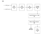
Referring now to FIG. 1, shown is a block diagram of an architecture of a tuning circuit for a tunable power performance loadline technique in accordance with an embodiment of the present invention. In the embodiment of FIG. 1, each logical thread can provide an input, namely an energy performance bias value, referred to herein as an EPB value. Note that this logical thread can correspond to a logical processor or other execution entity. The policy choice between performance and power can be provided per logical thread via a register or other storage, e.g., a 4-bit input register. In this example, 16 levels of power and performance tradeoff can be realized, in such an embodiment. According to one convention, a value of zero represents a very low (or even zero) tolerance for performance loss while saving power. On the other hand a value of 15 represents a high tolerance for performance loss and saving as much power as possible. Note that this EPB input can be provided by an operating system (OS) or by system basic input/output system (BIOS), or even by a user level application directly or indirectly.
In one usage model, where an operating system supports multiple power/performance profiles, the OS configures the energy performance bias register to an appropriate value based the power/performance profile chosen by an administrator which is one example of an end user. To this end, embodiments may provide a user interface to request and receive user selection of a given EPB value. This user interface functionality can be accommodated within BIOS or an OS or other custom system level software. In an advanced usage model, a data center administrator or other information technology personnel can provide the input based on time of day policies. For example, during times of peak usage, the administrator can choose to configure a value of 0 while during non-peak hours the administrator can choose to configure the server to a value of 15 to save as much power as possible.
In another usage model for advanced application level control that supports the option for application monitoring of the level of performance that the application expects to receive under a level of service agreement, the application may tune through an OS service the level of performance loss that is acceptable by the application under its current level of operation.
As seen in FIG. 1, a power management tuning circuit 100 can be used to receive incoming EPB values from multiple cores of a multicore processor and use these values to determine an appropriate tradeoff between power and performance policies and provide settings to the agents responsible for controlling various power management features of a system including the processor. In one embodiment, circuit 100 can be implemented in logic of a power control unit (PCU) of a processor, although embodiments can be implemented in other hardware or software. As seen, circuit 100 includes a sampler 110 that can receive incoming EPB values from the various cores. Note that these values received can be from logical threads, in one embodiment, which provide a value based on its programming. Although described in the embodiment of FIG. 1 as being received from cores, in various embodiments, EPB values can be per core's thread, per core or per package that includes a number of cores, or other granularity. By these multiple inputs, thread specific optimizations can be made based on a workload being executed. Received EPB values can be stored in temporary storage, e.g., registers within EPB sampler 110 at a sampling point, which may be according to a given interval. In one embodiment, the EPB inputs can be sampled at a predetermined interval, e.g., once every 1 millisecond (ms). The samples obtained from the various cores can be provided to an EPB combiner 120 that can generate a single value from these multiple values. For power management optimizations that are not thread specific (for example, of a memory controller, interconnect, memory or so forth), a mechanism can be provided to resolve the inputs from the multiple threads. In one embodiment, this resolution can be via a policy of favoring performance. To this end, a min function can be performed on all thread's inputs and the resulting value represents the most performance favoring EPB input. This value can then be used to determine the processor power/performance policy level. However, understand the scope of the present invention is not limited in this way. As an example instead of a minimum function, an averaging between the individual thread values can be performed. Another example is to make the minimum function per control power domain that may hold several sets of cores or threads.
Still referring to FIG. 1, the single value corresponding to, e.g., the minimum value of the EPB value, can be provided to a bin generator 130. Note that in various embodiments this bin generator may be optional to provide for finer-grained control. That is, bin generator 130 may generalize the tuning by taking the received EPB value and placing it into one of multiple bins that correspond to multiple coarser-grained levels of control such that the EPB value thus determined can be bucketed into an internal value. As described above, with a 4-bit EPB value, 16 levels can be provided. However, some systems may not be sufficiently complex with regard to the number of power management features, and thus the determined EPB value can be corresponded to one of N bins less than 16 individual levels. In one embodiment, to simplify and minimize the amount of tuning for a processor, the EPB value can be allocated to one of N buckets or bins. N can equal four, in one embodiment. In this example, each bucket represents a continuous range that is ¼th of total power management range. These buckets may directly map to power/performance profiles supported by certain operating systems. Table 2 shows the tuning criterion for four buckets in accordance with one embodiment of the present invention. However, understand that different tuning criteria can be used in other embodiments.
TABLE 2
Resolved
EPB Input Power Management Feature Tuning
Range Power Profile Target
0-3 Performance Tolerate up to 0.1% performance loss
4-7 Balanced Tolerate up to 2% performance loss.
Performance Power saving should be at least 2x
performance loss.
 8-11 Balanced Power Tolerate up to 5% performance loss.
Power saving should be at least 1x
performance loss.
12-15 Power Saver Tolerate >5% performance loss. Save
as much power as possible.
Still referring to FIG. 1, the bin value thus determined can be provided to a change detector 140 that can determine whether the value of the bin has changed since the last analysis interval. If not, no further operation of circuit 100 may be performed for that analysis interval. If instead the value has changed, this new value can be used to access a power/performance table 150. In various embodiments, this table can be stored in a processor, e.g., in non-volatile storage of the PCU. The table can be pre-tuned to provide user transparent tuning settings that correspond to a selected power/performance profile. In general, table 150 can include one or more entries for each power management feature. Each entry can further include a plurality of fields, each associated with one of the buckets (or indicated EPB values) to store a parameter for use in that feature or setting of a feature. These parameters may be values used for a certain power management feature, or can be an address to code that is executed for a given setting.
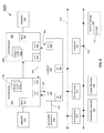
Referring now to FIG. 2, shown is a block diagram of a tuning table in accordance with an embodiment of the present invention. As shown in FIG. 2, table 150 includes multiple entries 151 0-151 n. As seen, each of these entries can be associated with a given power management feature setting. Some features may have more than one setting associated with them. For other power management features, only an entry for a single setting is provided.
As further seen in table 150, each entry includes a plurality of fields. In the embodiment shown in FIG. 2, fields 152, 154, 156 and 158 are provided. Each field is associated with a given one of the multiple bins as discussed above, namely a given policy. In other embodiments, each field can be associated with a given EPB value. Thus for each power management feature setting, every bin can have a value in its corresponding field. In specific implementations, each field may include a value that can be used to control enablement of a power management feature, provide a configuration register value or so forth. For some features and settings, it is possible that multiple bins may have the same value, however the scope of the present invention is not limited in this aspect.
Based on the bin value, a respective column of the table can be accessed and all of the fields of the accessed column can be read out, e.g., as a single vector read or iteratively via a field of an entry per cycle. As will be discussed below, these values output from the table can be provided to a change detector 160. Although shown at this high level in the embodiment of FIG. 3, understand the scope of the present invention is not limited in this regard.
In some embodiments, in addition to the EPB input, a workload configuration input can be provided. To this end, the table can have 3 dimensions such that based on the workload configuration input, a different set of entries for the defined power management features can be accessed, as different values may be present in the table for different workload configurations. By this workload configuration input a vertical user having an understanding and control of the exact workloads running on their systems can benefit from well-tuned settings. As examples, a user can configure a workload input as non-uniform memory architecture (NUMA), uniform memory architecture (UMA), input/output (I/O) intensive, etc. This input allows for choosing tuning settings that favor a specific workload pattern. For example, if the workload is NUMA, aggressive settings can be applied to off-chip interconnects such as Intel® Quick Path Interconnect (QPI) links to save as much power possible while causing very little performance impact, as off-chip accesses can be expected to be low. Thus for embodiments in which a workload configuration input is provided, it can be used as an additional input to access the table.
Once a new set of configurations is determined from access to the tuning table, the target features can be updated. There are two classes of configurations. For features like a power C-state auto demotion and turbo upside clipping, the configurations can be internal to power management code, such as present in firmware of the PCU. In this case the update can be effected by loading new values into an internal feature specific data structure such as one or more configuration registers. In a second class of configuration, the configuration value is specific to an entity that resides outside the PCU. For example, a clock related configuration can be implemented in the memory controller. In this case, the PCU can initiate a series of writes to target configuration space to update the settings. In order to minimize the number of writes, each configuration value can be compared to the previous value and a write is issued only if the actual configuration value changes.
Accordingly, with further reference back to FIG. 1 the identified field of the multiple entries of table 150 can be output to a change detector 160 to determine whether the values have changed from the previous output. Note that for certain power management features, settings may not change when a bin changes level. Thus change detector 160 acts as a filter to filter from sending messages for updates when in fact no update is needed. If a change in fact has occurred, it may be sent from change detector 160 to the indicated destination. As described, many power management features can be controlled using the PCU, and accordingly updated settings can be sent to a PCU updater 170 which thus may update the settings, e.g., by updating values in configuration registers, other storages, enabling or disabling certain power management features, changing variables used with regard to duration of power management features or so forth.
If instead the power management feature is for a non-PCU controlled feature, update messages can be sent to the destination, e.g., via one or more write messages including the information. Although shown with this particular implementation in the embodiment of FIG. 1, understand the scope of the present invention is not limited in this regard.
Referring now to FIG. 3, shown is a flow diagram of a method in accordance with an embodiment of the present invention. As seen, method 200 can be performed, e.g., using policy management logic of a PCU or other power controller. Method 200 begins by receiving an energy performance bias value from multiple threads (block 210). As discussed above, these threads can be logical threads or equivalently the EPB values can be received from the cores themselves. Next, a global EPB value can be determined from the received EPB values (block 220). For example, a min function can be performed or an average obtained from these multiple values. Then, this global EPB value can be placed into a bin of multiple performance level bins (block 230). Such binning provides a smoothing function, although it may not be present in some implementations where very fine-grained control of power and performance tradeoffs is desired.
Still referring to FIG. 3, control next passes to diamond 240 where it can be determined whether a bin change has occurred since the last evaluation interval. If not, method 200 concludes for that given evaluation interval which can be, e.g., on the order of approximately 1 ms.
If instead a bin change has occurred, control passes to block 250 where a power-performance table can be accessed based on the bin. This table access thus can be used to read out for the given bin, and for each of multiple power management features, one or more settings or other values used to control the power management feature. This reading and the updating process can be performed iteratively for each feature. Thus it can be determined whether an additional power management features present in the table (diamond 255). If not, method 200 terminates for that evaluation interval. If another feature is present, it can be determined whether a change in the feature settings has occurred since the last read out from the table (diamond 260). If not control passes back to diamond 255. If instead a feature change has occurred, control passes to diamond 270 where it can be determined whether the feature is a PCU-controlled feature. If so, one or more settings for the feature can be updated in the PCU (block 290). Such updating can be via configuration register updates or so forth. Otherwise if the updates are for a power management feature controlled by an external agent, control passes to block 280 where one or more messages, e.g., write messages can be sent to the destination agent to update the settings accordingly. For example, writes can be issued to target using a given message channel (e.g., QPI, integrated memory controller, a Peripheral Component Interconnect Express (PCI Express™ (PCIe™)) link or so forth). Although shown with this particular implementation in the embodiment of FIG. 3, understand the scope of the present invention is not limited in this regard.
In one embodiment, a tuning methodology for generating to power-performance table may include the following. First, each individual power management feature is tuned separately while the other features are turned off. This tuning includes generating a power/performance profile across a range of workloads for each feature. As an example various benchmark workloads can be executed to generate the profile. Second, multiple features can be enabled to a profile whether the power/performance tradeoff met the tuning goals for overall power/performance profile. Then individual feature tunings can be adjusted to meet overall power/performance profile goals. The above steps can be repeated until overall goals are reached.
By default the operating system may populate the EPB input with a profile chosen by the end user. This tuning can be achieved via an iterative process in which different EPB values are input and workloads run with each setting. As the EPB input is tuned towards power savings, a user may notice a continuous degradation of response time (performance). Once a desired response time is met, the EPB value may correspond to a desired maximum power savings for the user's specific usage. This in essence is the goal of the tunable power performance loadline, as each end user can tune the power/performance loadline to his specific usage.
Embodiments can be implemented in processors for various markets including server processors, desktop processors, mobile processors, and so forth. Referring now to FIG. 4, shown is a block diagram of a processor in accordance with an embodiment of the present invention. As shown in FIG. 4, processor 300 may be a multicore processor including a plurality of cores 310 a-310 n. In one embodiment, each such core may be of an independent power domain and can be configured to operate at an independent voltage and/or frequency, and to enter turbo mode when available headroom exists. The various cores may be coupled via an interconnect 315 to a system agent or uncore 320 that includes various components. As seen, the uncore 320 may include a shared cache 330 which may be a last level cache. In addition, the uncore may include an integrated memory controller 340, various interfaces 350 and a power control unit 355.
In various embodiments, power control unit 355 may include a policy tuning logic 359, which may be a logic to perform dynamic control of power management settings based on an input EPB value. As further seen, a tuning table 357 can be present to store power management feature settings. This tuning table generated, e.g., during design of the processor, based on benchmark workload testing on the processor may be used to determine appropriate settings for the different power management policies that map to EPB values or bins.
With further reference to FIG. 4, processor 300 may communicate with a system memory 360, e.g., via a memory bus. In addition, by interfaces 350, connection can be made to various off-chip components such as peripheral devices, mass storage and so forth. While shown with this particular implementation in the embodiment of FIG. 4, the scope of the present invention is not limited in this regard.
Referring now to FIG. 5, shown is a block diagram of a multi-domain processor in accordance with another embodiment of the present invention. As shown in the embodiment of FIG. 5, processor 400 includes multiple domains. Specifically, a core domain 410 can include a plurality of cores 410 0-410 n, a graphics domain 420 can include one or more graphics engines, and a system agent domain 450 may further be present. In various embodiments, system agent domain 450 may execute at a fixed frequency and may remain powered on at all times to handle power control events and power management such that domains 410 and 420 can be controlled to dynamically enter into and exit low power states. Each of domains 410 and 420 may operate at different voltage and/or power. Note that while only shown with three domains, understand the scope of the present invention is not limited in this regard and additional domains can be present in other embodiments. For example, multiple core domains may be present each including at least one core.
In general, each core 410 may further include low level caches in addition to various execution units and additional processing elements. In turn, the various cores may be coupled to each other and to a shared cache memory formed of a plurality of units of a last level cache (LLC) 440 0-440 n. In various embodiments, LLC 440 may be shared amongst the cores and the graphics engine, as well as various media processing circuitry. As seen, a ring interconnect 430 thus couples the cores together, and provides interconnection between the cores, graphics domain 420 and system agent circuitry 450. In one embodiment, interconnect 430 can be part of the core domain. However in other embodiments the ring interconnect can be of its own domain.
As further seen, system agent domain 450 may include a display controller 452 which may provide control of and an interface to an associated display. As further seen, system agent domain 450 may include a power control unit 455 which can include a policy tuning logic 459 in accordance with an embodiment of the present invention to dynamically control power management settings obtained from a tuning table 457 based on one or more EPB values. In various embodiments, this logic may execute the algorithm described above in FIG. 3.
As further seen in FIG. 5, processor 400 can further include an integrated memory controller (IMC) 470 that can provide for an interface to a system memory, such as a dynamic random access memory (DRAM). Multiple interfaces 480 0-480 n may be present to enable interconnection between the processor and other circuitry. For example, in one embodiment at least one direct media interface (DMI) interface may be provided as well as one or more Peripheral Component Interconnect Express (PCI Express™ (PCIe™)) interfaces. Still further, to provide for communications between other agents such as additional processors or other circuitry, one or more interfaces in accordance with a Intel® Quick Path Interconnect (QPI) protocol may also be provided. Although shown at this high level in the embodiment of FIG. 5, understand the scope of the present invention is not limited in this regard.
Embodiments may be implemented in many different system types. Referring now to FIG. 6, shown is a block diagram of a system in accordance with an embodiment of the present invention. As shown in FIG. 6, multiprocessor system 500 is a point-to-point interconnect system, and includes a first processor 570 and a second processor 580 coupled via a point-to-point interconnect 550. As shown in FIG. 6, each of processors 570 and 580 may be multicore processors, including first and second processor cores (i.e., processor cores 574 a and 574 b and processor cores 584 a and 584 b), although potentially many more cores may be present in the processors. Each of the processors can include a PCU or other logic to perform dynamic control of power management settings based on a resolved power management policy, as described herein.
Still referring to FIG. 6, first processor 570 further includes a memory controller hub (MCH) 572 and point-to-point (P-P) interfaces 576 and 578. Similarly, second processor 580 includes a MCH 582 and P-P interfaces 586 and 588. As shown in FIG. 6, MCH's 572 and 582 couple the processors to respective memories, namely a memory 532 and a memory 534, which may be portions of system memory (e.g., DRAM) locally attached to the respective processors. First processor 570 and second processor 580 may be coupled to a chipset 590 via P-P interconnects 552 and 554, respectively. As shown in FIG. 6, chipset 590 includes P-P interfaces 594 and 598.
Furthermore, chipset 590 includes an interface 592 to couple chipset 590 with a high performance graphics engine 538, by a P-P interconnect 539. In turn, chipset 590 may be coupled to a first bus 516 via an interface 596. As shown in FIG. 6, various input/output (I/O) devices 514 may be coupled to first bus 516, along with a bus bridge 518 which couples first bus 516 to a second bus 520. Various devices may be coupled to second bus 520 including, for example, a keyboard/mouse 522, communication devices 526 and a data storage unit 528 such as a disk drive or other mass storage device which may include code 530, in one embodiment. Further, an audio I/O 524 may be coupled to second bus 520. Embodiments can be incorporated into other types of systems including mobile devices such as a smart cellular telephone, tablet computer, netbook, ultrabook, or so forth.
FIG. 7 is a block diagram of a system 600 coupled with point-to-point (PtP) system interconnects in accordance with a given cache coherence protocol using QPI links as the system interconnect. In the embodiment shown, each processor 610 is coupled to two PtP links 625 and includes one instance of an integrated memory controller 615 that in turn is coupled to a corresponding local portion of a system memory 620. Each processor can perform power management techniques using optimized settings obtained from a tuning table in accordance with an embodiment of the present invention. The processors are connected to an input/output hub (IOH) 630 using one link and the remaining link is used to connect the two processors.
Referring now to FIG. 8, shown is a block diagram of a system in accordance with another embodiment of the present invention. As shown in FIG. 8, system 700 may be a partially connected quad processor system in which each processor 710 (each of which may be multicore multi-domain processors) is coupled to each other processor via a PtP link and is coupled to a local portion of memory (e.g., dynamic random access memory (DRAM)) 720 via a memory interconnect coupled to an integrated memory controller 715 of the corresponding processor. In the partially connected system of FIG. 8, note the presence of two IOHs 730 and 740 such that processors 710 0 and 710 1 are directly coupled to IOH 730 and similarly processors 710 2 and 710 3 are directly coupled to IOH 740.
Embodiments may be implemented in code and may be stored on a non-transitory storage medium having stored thereon instructions which can be used to program a system to perform the instructions. The storage medium may include, but is not limited to, any type of disk including floppy disks, optical disks, solid state drives (SSDs), compact disk read-only memories (CD-ROMs), compact disk rewritables (CD-RWs), and magneto-optical disks, semiconductor devices such as read-only memories (ROMs), random access memories (RAMs) such as dynamic random access memories (DRAMs), static random access memories (SRAMs), erasable programmable read-only memories (EPROMs), flash memories, electrically erasable programmable read-only memories (EEPROMs), magnetic or optical cards, or any other type of media suitable for storing electronic instructions.
While the present invention has been described with respect to a limited number of embodiments, those skilled in the art will appreciate numerous modifications and variations therefrom. It is intended that the appended claims cover all such modifications and variations as fall within the true spirit and scope of this present invention.

Claims (18)

What is claimed is:
1. A processor comprising:
a plurality of cores and a power controller to control a plurality of power management features of the processor, the power controller to receive a workload configuration input and receive an energy performance bias (EPB) value corresponding to a single input value from at least some of the plurality of cores and determine global EPB value based thereon, to control the plurality of power management features and to update at least one setting of at least one of the plurality of power management features based on the workload configuration input and the global EPB value.
2. The processor of claim 1, wherein the power controller is to access a power-performance tuning table based on the workload configuration input and the global EPB value, and to use information from the power-performance tuning table to update the at least one setting.
3. The processor of claim 2, wherein the power controller includes a tuning circuit to update the at least one setting of the at least one power management feature responsive to the global EPB value.
4. The processor of claim 3, wherein the tuning circuit includes a sampler to receive an EPB value from the plurality of cores and a combiner to generate the global EPB value from the EPB value from the plurality of cores.
5. The processor of claim 4, wherein the power controller is to generate a bin value from the global EPB value and to access the power-performance tuning table using the bin value.
6. The processor of claim 3, wherein the tuning circuit is to update at least one setting of a first power management feature controlled by the power controller, and to send a message to an interconnect that couples the processor to a second component of a system to update at least one setting of a second power management feature controlled by the interconnect.
7. The processor of claim 2, wherein the power-performance tuning table includes a plurality of entries each having a plurality of fields each associated with a range of the EPB value and including a setting for a power management feature, wherein the power-performance tuning table is configured based on a plurality of characterization workloads to provide user transparent tuning.
8. The processor of claim 7, wherein the power-performance tuning table includes a first set of entries associated with the plurality of power management features and further accessed by a workload configuration value for a first workload type and a second set of entries associated with the plurality of power management features and further accessed by a workload configuration value for a second workload type.
9. A non-transitory machine-readable medium having stored thereon instructions, which if performed by a machine cause the machine to perform a method comprising:
receiving an energy performance bias (EPB) value in a power controller of a processor of a system from a plurality of threads executing on the processor and determining a global EPB value using the EPB value received from the plurality of threads, the EPB value to indicate a preference of a user for a tradeoff between power optimization and performance optimization;
accessing a power-performance table based on the global EPB value; and
updating at least one setting of a power management feature controlled by the power controller based on information obtained from the power-performance table.
10. The non-transitory machine-readable medium of claim 9, wherein the method further comprises selecting a bin of a plurality of bins, each associated with a power-performance profile using the global EPB value.
11. The non-transitory machine-readable medium of claim 10, wherein accessing the power-performance table based on the global EPB value includes accessing the power-performance table using the selected bin, and updating at least one setting of a first power management feature controlled by the power controller, the at least one setting obtained from a field of an entry of the power-performance table associated with the selected bin.
12. The non-transitory machine-readable medium of claim 11, wherein the method further comprises sending a message to a target agent coupled to the processor, the message including at least one updated setting for a second power management feature controlled by the target agent, the at least one setting obtained from a field of an entry of the power-performance table associated with the selected bin.
13. The non-transitory machine-readable medium of claim 9, wherein the method further comprises providing an interface to enable a user, an operating system or a baseboard management controller to set the EPB value, and controlling a plurality of power management features via input of the EPB value.
14. The non-transitory machine-readable medium of claim 9, wherein the method further comprises receiving the EPB value with a first value for a first portion of a day and with a second value for a second portion of the day, wherein the first value is to configure the system for first performance during the first portion of the day corresponding to peak user hours, and the second value to configure the system for higher power savings during the second portion of the day corresponding to non-peak user hours.
15. The non-transitory machine-readable medium of claim 9, wherein the method further comprises receiving a first plurality of EPB values during a tuning process and iteratively updating at least some power management feature settings for each of the first plurality of EPB values, wherein responsive to performance of the system with the updated power management features, a user selects a desired one of the first plurality of EPB values.
16. A system comprising:
a multicore processor including a plurality of cores and a tuning circuit to dynamically select a balance between a power consumption level and a performance level based on an energy performance bias (EPB) value, wherein the tuning circuit is to access an entry of a tuning table based at least in part on the EPB value and a workload configuration value, and to update a setting for a power management feature responsive to a value stored in a field of the entry associated with the EPB value, wherein the workload configuration value is to indicate a predominant workload type to be executed on the system, the tuning table including a first set of entries associated with a first workload type and a second set of entries associated with a second workload type; and
a dynamic random access memory (DRAM) coupled to the processor via a memory interconnect.
17. The system of claim 16, wherein tuning circuit is to update at least one setting of a first power management feature controlled by a power controller of the multicore processor, the at least one setting obtained from a field of an entry of the tuning table associated with a bin in which the EPB value is included.
18. The system of claim 17, wherein the tuning circuit is to send a message to the memory interconnect, the message including at least one updated setting for a second power management feature controlled by the memory interconnect, the at least one updated setting obtained from a field of an entry of the tuning table associated with the bin.
US13/782,473 2011-12-15 2013-03-01 User level control of power management policies Active 2032-08-28 US9170624B2 (en)

Priority Applications (3)

Application Number Priority Date Filing Date Title
US13/782,473 US9170624B2 (en) 2011-12-15 2013-03-01 User level control of power management policies
US14/855,553 US9535487B2 (en) 2011-12-15 2015-09-16 User level control of power management policies
US15/367,330 US10372197B2 (en) 2011-12-15 2016-12-02 User level control of power management policies

Applications Claiming Priority (2)

Application Number Priority Date Filing Date Title
US13/326,586 US9098261B2 (en) 2011-12-15 2011-12-15 User level control of power management policies
US13/782,473 US9170624B2 (en) 2011-12-15 2013-03-01 User level control of power management policies

Related Parent Applications (1)

Application Number Title Priority Date Filing Date
US13/326,586 Continuation US9098261B2 (en) 2011-12-15 2011-12-15 User level control of power management policies

Related Child Applications (1)

Application Number Title Priority Date Filing Date
US14/855,553 Continuation US9535487B2 (en) 2011-12-15 2015-09-16 User level control of power management policies

Publications (2)

Publication Number Publication Date
US20130179706A1 US20130179706A1 (en) 2013-07-11
US9170624B2 true US9170624B2 (en) 2015-10-27

Family

ID=46601496

Family Applications (4)

Application Number Title Priority Date Filing Date
US13/326,586 Active 2034-02-08 US9098261B2 (en) 2011-12-15 2011-12-15 User level control of power management policies
US13/782,473 Active 2032-08-28 US9170624B2 (en) 2011-12-15 2013-03-01 User level control of power management policies
US14/855,553 Active US9535487B2 (en) 2011-12-15 2015-09-16 User level control of power management policies
US15/367,330 Active US10372197B2 (en) 2011-12-15 2016-12-02 User level control of power management policies

Family Applications Before (1)

Application Number Title Priority Date Filing Date
US13/326,586 Active 2034-02-08 US9098261B2 (en) 2011-12-15 2011-12-15 User level control of power management policies

Family Applications After (2)

Application Number Title Priority Date Filing Date
US14/855,553 Active US9535487B2 (en) 2011-12-15 2015-09-16 User level control of power management policies
US15/367,330 Active US10372197B2 (en) 2011-12-15 2016-12-02 User level control of power management policies

Country Status (4)

Country Link
US (4) US9098261B2 (en)
CN (1) CN103988145B (en)
TW (1) TWI482008B (en)
WO (1) WO2013090627A1 (en)

Cited By (2)

* Cited by examiner, † Cited by third party
Publication number Priority date Publication date Assignee Title
US20160004291A1 (en) * 2011-12-15 2016-01-07 Intel Corporation User Level Control Of Power Management Policies
US10761584B2 (en) 2018-03-16 2020-09-01 Vigyanlabs Innovations Private Limited System and method to enable prediction-based power management

Families Citing this family (19)

* Cited by examiner, † Cited by third party
Publication number Priority date Publication date Assignee Title
US9098309B2 (en) 2011-09-23 2015-08-04 Qualcomm Incorporated Power consumption optimized translation of object code partitioned for hardware component based on identified operations
US20130185581A1 (en) * 2012-01-18 2013-07-18 Qualcomm Incorporated Efficient Code Dispatch Based on Performance and Energy Consumption
US9547027B2 (en) 2012-03-30 2017-01-17 Intel Corporation Dynamically measuring power consumption in a processor
CN104951031A (en) * 2014-03-28 2015-09-30 伊姆西公司 Power management equipment, power management method and power management system
US9128729B1 (en) 2014-09-08 2015-09-08 Quanta Computer Inc. System and method for automatically configuring bios performance profiles
US10666682B2 (en) * 2014-10-15 2020-05-26 Marvell Asia Pte, Ltd. Systems and methods for allowing flexible chip configuration by external entity while maintaining secured boot environment
US9880601B2 (en) 2014-12-24 2018-01-30 Intel Corporation Method and apparatus to control a link power state
WO2016153379A1 (en) * 2015-03-26 2016-09-29 Huawei Technologies Co., Ltd Scheduler device and method for dynamic loop-to-processor mapping
US9713192B2 (en) * 2015-03-27 2017-07-18 Intel Corporation Device and method for processing audio data
US10162405B2 (en) * 2015-06-04 2018-12-25 Intel Corporation Graphics processor power management contexts and sequential control loops
US9864667B2 (en) * 2015-09-25 2018-01-09 Intel Corporation Techniques for flexible and dynamic frequency-related telemetry
US9971391B2 (en) * 2015-12-23 2018-05-15 Intel Corporation Method to assess energy efficiency of HPC system operated with and without power constraints
US10146286B2 (en) * 2016-01-14 2018-12-04 Intel Corporation Dynamically updating a power management policy of a processor
WO2017171973A1 (en) * 2016-04-01 2017-10-05 Intel Corporation Method and apparatus to optimize power settings for a workload
US10649943B2 (en) * 2017-05-26 2020-05-12 Dell Products, L.P. System and method for I/O aware processor configuration
US10585816B1 (en) * 2018-12-07 2020-03-10 Dell Products, L.P. System and method for serial communication at a peripheral interface device
US11095495B2 (en) * 2019-04-05 2021-08-17 Arista Networks, Inc. Multi-result lookups
US11157329B2 (en) 2019-07-26 2021-10-26 Intel Corporation Technology for managing per-core performance states
US20230031805A1 (en) * 2021-07-30 2023-02-02 Texas Instruments Incorporated Multi-level power management operation framework

Citations (70)

* Cited by examiner, † Cited by third party
Publication number Priority date Publication date Assignee Title
US5163153A (en) 1989-06-12 1992-11-10 Grid Systems Corporation Low-power, standby mode computer
US5522087A (en) 1994-03-22 1996-05-28 Verifone Inc. System for selectively operating in different modes depending upon receiving signal from a host computer within a time window upon power up
US5590341A (en) 1994-09-30 1996-12-31 Intel Corporation Method and apparatus for reducing power consumption in a computer system using ready delay
US5621250A (en) 1995-07-31 1997-04-15 Ford Motor Company Wake-up interface and method for awakening an automotive electronics module
US5931950A (en) 1997-06-17 1999-08-03 Pc-Tel, Inc. Wake-up-on-ring power conservation for host signal processing communication system
US20010044909A1 (en) 2000-05-15 2001-11-22 Lg Electronics Inc. Method and apparatus for adjusting clock throttle rate based on usage of CPU
US20020194509A1 (en) 2001-06-15 2002-12-19 Microsoft Corporation Method and system for using idle threads to adaptively throttle a computer
EP1282030A1 (en) 2000-05-08 2003-02-05 Mitsubishi Denki Kabushiki Kaisha Computer system and computer-readable recording medium
US20030061383A1 (en) 2001-09-25 2003-03-27 Zilka Anthony M. Predicting processor inactivity for a controlled transition of power states
TW200301025A (en) 2001-11-26 2003-06-16 Ebauchesfabrik Eta Ag VHF wave receiver antenna housed in a wristband of a portable electronic device
US20040064752A1 (en) 2002-09-30 2004-04-01 Kazachinsky Itamar S. Method and apparatus for reducing clock frequency during low workload periods
US20040098560A1 (en) 2002-11-15 2004-05-20 Storvik Alvin C. Paging scheme for a microcontroller for extending available register space
US6748546B1 (en) 2000-09-26 2004-06-08 Sun Microsystems, Inc. Method and apparatus for reducing power consumption
US20040139356A1 (en) 2003-01-10 2004-07-15 Kenneth Ma Method and apparatus for improving bus master performance
US6792392B1 (en) 2000-06-30 2004-09-14 Intel Corporation Method and apparatus for configuring and collecting performance counter data
US6823516B1 (en) 1999-08-10 2004-11-23 Intel Corporation System and method for dynamically adjusting to CPU performance changes
US6829713B2 (en) 2000-12-30 2004-12-07 Intel Corporation CPU power management based on utilization with lowest performance mode at the mid-utilization range
US20040268166A1 (en) 2003-06-30 2004-12-30 Farkas Keith Istvan Controlling power consumption of at least one computer system
US20050022038A1 (en) 2003-07-23 2005-01-27 Kaushik Shivnandan D. Determining target operating frequencies for a multiprocessor system
US20050033881A1 (en) 2003-07-08 2005-02-10 Benq Corporation Method and apparatus for multi-interrupt controller for reducing hardware interrupts to DSP
US20050066206A1 (en) 2003-09-24 2005-03-24 John Beers Storage device configuration
US20050132238A1 (en) 2003-12-16 2005-06-16 Murthi Nanja Performance monitoring based dynamic voltage and frequency scaling
US20050289369A1 (en) 2004-06-25 2005-12-29 Chien-Ping Chung System and method of real-time power management
US6996728B2 (en) 2002-04-26 2006-02-07 Hewlett-Packard Development Company, L.P. Managing power consumption based on utilization statistics
US7010708B2 (en) 2002-05-15 2006-03-07 Broadcom Corporation Method and apparatus for adaptive CPU power management
US20060053326A1 (en) 2004-09-03 2006-03-09 Intel Corporation Coordinating idle state transitions in multi-core processors
US20060050670A1 (en) 2004-09-07 2006-03-09 Jason Hillyard Method and system for low power mode management for complex bluetooth devices
US20060059286A1 (en) 2004-09-10 2006-03-16 Cavium Networks Multi-core debugger
US20060069936A1 (en) 2004-09-30 2006-03-30 Lint Bernard J Global and pseudo power state management for multiple processing elements
US7043649B2 (en) 2002-11-20 2006-05-09 Portalplayer, Inc. System clock power management for chips with multiple processing modules
US20060117202A1 (en) 2004-11-29 2006-06-01 Grigorios Magklis Frequency and voltage scaling architecture
US7093147B2 (en) 2003-04-25 2006-08-15 Hewlett-Packard Development Company, L.P. Dynamically selecting processor cores for overall power efficiency
US20060184287A1 (en) 2005-02-15 2006-08-17 Belady Christian L System and method for controlling power to resources based on historical utilization data
US7111179B1 (en) 2001-10-11 2006-09-19 In-Hand Electronics, Inc. Method and apparatus for optimizing performance and battery life of electronic devices based on system and application parameters
US20070005995A1 (en) 2005-06-30 2007-01-04 Kardach James P Power management system for computing platform
US20070016817A1 (en) 2003-01-23 2007-01-18 David Albonesi Multiple clock domain microprocessor
US7194643B2 (en) 2003-09-29 2007-03-20 Intel Corporation Apparatus and method for an energy efficient clustered micro-architecture
US20070079294A1 (en) 2005-09-30 2007-04-05 Robert Knight Profiling using a user-level control mechanism
US20070106827A1 (en) 2005-11-08 2007-05-10 Boatright Bryan D Centralized interrupt controller
US20070156992A1 (en) 2005-12-30 2007-07-05 Intel Corporation Method and system for optimizing latency of dynamic memory sizing
US20070214342A1 (en) 2005-09-23 2007-09-13 Newburn Chris J System to profile and optimize user software in a managed run-time environment
US7272730B1 (en) 2003-07-31 2007-09-18 Hewlett-Packard Development Company, L.P. Application-driven method and apparatus for limiting power consumption in a processor-controlled hardware platform
US20070239398A1 (en) 2006-03-30 2007-10-11 Justin Song Performance state management
US20070245163A1 (en) 2006-03-03 2007-10-18 Yung-Hsiang Lu Power management in computer operating systems
US20080028240A1 (en) 2006-07-31 2008-01-31 Susumu Arai System and method for controlling processor low power states
US7376849B2 (en) 2004-06-30 2008-05-20 Intel Corporation Method, apparatus and system of adjusting one or more performance-related parameters of a processor
US7412615B2 (en) 2003-02-10 2008-08-12 Sony Corporation Information processing equipment and power consumption control method
US20080250260A1 (en) 2007-04-06 2008-10-09 Kabushiki Kaisha Toshiba Information processing apparatus, scheduler, and schedule control method of information processing apparatus
US7454632B2 (en) 2005-06-16 2008-11-18 Intel Corporation Reducing computing system power through idle synchronization
US20090006871A1 (en) 2007-06-28 2009-01-01 Yen-Cheng Liu Method, system, and apparatus for a core activity detector to facilitate dynamic power management in a distributed system
US7529956B2 (en) 2006-07-17 2009-05-05 Microsoft Corporation Granular reduction in power consumption
US7539885B2 (en) 2000-01-13 2009-05-26 Broadcom Corporation Method and apparatus for adaptive CPU power management
US20090150695A1 (en) 2007-12-10 2009-06-11 Justin Song Predicting future power level states for processor cores
US20090150696A1 (en) 2007-12-10 2009-06-11 Justin Song Transitioning a processor package to a low power state
US20090158067A1 (en) 2007-12-12 2009-06-18 Bodas Devadatta V Saving power in a computer system
US20090158061A1 (en) 2007-12-18 2009-06-18 Packet Digital Method and apparatus for on-demand power management
US20090172428A1 (en) 2007-12-26 2009-07-02 Jung Hwan Lee Apparatus and method for controlling power management
US20090172375A1 (en) 2004-12-30 2009-07-02 Intel Corporation Operating Point Management in Multi-Core Architectures
US20090177334A1 (en) 2008-01-04 2009-07-09 Dell Products L.P. Method and System for Managing the Power Consumption of an Information Handling System
US20090235105A1 (en) 2008-03-11 2009-09-17 Alexander Branover Hardware Monitoring and Decision Making for Transitioning In and Out of Low-Power State
US20090254660A1 (en) 2008-04-07 2009-10-08 Hanson James E Systems and methods for coordinated management of power usage and runtime performance in performance-managed computing environments
US20090327785A1 (en) 2008-06-30 2009-12-31 Acer Incorporated Power management device and method thereof for managing power consumption of electronic device
US20100115309A1 (en) 2007-03-26 2010-05-06 Freescale Semiconductor, Inc. Anticipation of power on of a mobile device
US7730340B2 (en) 2007-02-16 2010-06-01 Intel Corporation Method and apparatus for dynamic voltage and frequency scaling
US20100146513A1 (en) 2008-12-09 2010-06-10 Intel Corporation Software-based Thread Remapping for power Savings
US20100191997A1 (en) 2006-06-06 2010-07-29 Intel Corporation Predict computing platform memory power utilization
US20100218029A1 (en) 2009-02-23 2010-08-26 International Business Machines Corporation System and Method for Managing the Power-Performance Range of an Application
US20110154090A1 (en) 2009-12-22 2011-06-23 Dixon Martin G Controlling Time Stamp Counter (TSC) Offsets For Mulitple Cores And Threads
US20110296212A1 (en) 2010-05-26 2011-12-01 International Business Machines Corporation Optimizing Energy Consumption and Application Performance in a Multi-Core Multi-Threaded Processor System
US20130179706A1 (en) 2011-12-15 2013-07-11 Krishnakanth V. Sistla User Level Control Of Power Management Policies

Family Cites Families (10)

* Cited by examiner, † Cited by third party
Publication number Priority date Publication date Assignee Title
ATE320111T1 (en) 2002-01-11 2006-03-15 Heidenhain Gmbh Dr Johannes METHOD FOR INTERPOLATION OF AT LEAST TWO POSITION-DEPENDENT, PERIODIC, PHASE-SHIFTED ANALOG SIGNALS
JP4450586B2 (en) 2003-09-03 2010-04-14 株式会社ルネサステクノロジ Semiconductor integrated circuit
US7295949B2 (en) * 2004-06-28 2007-11-13 Broadcom Corporation Energy efficient achievement of integrated circuit performance goals
US7223697B2 (en) 2004-07-23 2007-05-29 International Business Machines Corporation Chemical mechanical polishing method
JP2006204576A (en) 2005-01-28 2006-08-10 Sharp Corp Washing machine
US8107728B2 (en) 2006-09-19 2012-01-31 Sharp Kabushiki Kaisha Image processing apparatus, image forming apparatus, image processing system, computer program and recording medium
US8739073B2 (en) 2007-05-15 2014-05-27 Microsoft Corporation User interface for document table of contents
US8245070B2 (en) * 2008-12-30 2012-08-14 Intel Corporation Method for optimizing voltage-frequency setup in multi-core processor systems
US8316368B2 (en) * 2009-02-05 2012-11-20 Honeywell International Inc. Safe partition scheduling on multi-core processors
US8793515B2 (en) * 2011-06-27 2014-07-29 Intel Corporation Increasing power efficiency of turbo mode operation in a processor

Patent Citations (74)

* Cited by examiner, † Cited by third party
Publication number Priority date Publication date Assignee Title
US5163153A (en) 1989-06-12 1992-11-10 Grid Systems Corporation Low-power, standby mode computer
US5522087A (en) 1994-03-22 1996-05-28 Verifone Inc. System for selectively operating in different modes depending upon receiving signal from a host computer within a time window upon power up
US5590341A (en) 1994-09-30 1996-12-31 Intel Corporation Method and apparatus for reducing power consumption in a computer system using ready delay
US5621250A (en) 1995-07-31 1997-04-15 Ford Motor Company Wake-up interface and method for awakening an automotive electronics module
US5931950A (en) 1997-06-17 1999-08-03 Pc-Tel, Inc. Wake-up-on-ring power conservation for host signal processing communication system
US6823516B1 (en) 1999-08-10 2004-11-23 Intel Corporation System and method for dynamically adjusting to CPU performance changes
US7539885B2 (en) 2000-01-13 2009-05-26 Broadcom Corporation Method and apparatus for adaptive CPU power management
EP1282030A1 (en) 2000-05-08 2003-02-05 Mitsubishi Denki Kabushiki Kaisha Computer system and computer-readable recording medium
US20010044909A1 (en) 2000-05-15 2001-11-22 Lg Electronics Inc. Method and apparatus for adjusting clock throttle rate based on usage of CPU
US6792392B1 (en) 2000-06-30 2004-09-14 Intel Corporation Method and apparatus for configuring and collecting performance counter data
US6748546B1 (en) 2000-09-26 2004-06-08 Sun Microsystems, Inc. Method and apparatus for reducing power consumption
US6829713B2 (en) 2000-12-30 2004-12-07 Intel Corporation CPU power management based on utilization with lowest performance mode at the mid-utilization range
US20020194509A1 (en) 2001-06-15 2002-12-19 Microsoft Corporation Method and system for using idle threads to adaptively throttle a computer
US20030061383A1 (en) 2001-09-25 2003-03-27 Zilka Anthony M. Predicting processor inactivity for a controlled transition of power states
US7111179B1 (en) 2001-10-11 2006-09-19 In-Hand Electronics, Inc. Method and apparatus for optimizing performance and battery life of electronic devices based on system and application parameters
TW200301025A (en) 2001-11-26 2003-06-16 Ebauchesfabrik Eta Ag VHF wave receiver antenna housed in a wristband of a portable electronic device
US6996728B2 (en) 2002-04-26 2006-02-07 Hewlett-Packard Development Company, L.P. Managing power consumption based on utilization statistics
US7010708B2 (en) 2002-05-15 2006-03-07 Broadcom Corporation Method and apparatus for adaptive CPU power management
US20040064752A1 (en) 2002-09-30 2004-04-01 Kazachinsky Itamar S. Method and apparatus for reducing clock frequency during low workload periods
US20040098560A1 (en) 2002-11-15 2004-05-20 Storvik Alvin C. Paging scheme for a microcontroller for extending available register space
US7043649B2 (en) 2002-11-20 2006-05-09 Portalplayer, Inc. System clock power management for chips with multiple processing modules
US20040139356A1 (en) 2003-01-10 2004-07-15 Kenneth Ma Method and apparatus for improving bus master performance
US20070016817A1 (en) 2003-01-23 2007-01-18 David Albonesi Multiple clock domain microprocessor
US7412615B2 (en) 2003-02-10 2008-08-12 Sony Corporation Information processing equipment and power consumption control method
US7093147B2 (en) 2003-04-25 2006-08-15 Hewlett-Packard Development Company, L.P. Dynamically selecting processor cores for overall power efficiency
US20040268166A1 (en) 2003-06-30 2004-12-30 Farkas Keith Istvan Controlling power consumption of at least one computer system
US20050033881A1 (en) 2003-07-08 2005-02-10 Benq Corporation Method and apparatus for multi-interrupt controller for reducing hardware interrupts to DSP
US20050022038A1 (en) 2003-07-23 2005-01-27 Kaushik Shivnandan D. Determining target operating frequencies for a multiprocessor system
US7272730B1 (en) 2003-07-31 2007-09-18 Hewlett-Packard Development Company, L.P. Application-driven method and apparatus for limiting power consumption in a processor-controlled hardware platform
US20050066206A1 (en) 2003-09-24 2005-03-24 John Beers Storage device configuration
US7194643B2 (en) 2003-09-29 2007-03-20 Intel Corporation Apparatus and method for an energy efficient clustered micro-architecture
US20050132238A1 (en) 2003-12-16 2005-06-16 Murthi Nanja Performance monitoring based dynamic voltage and frequency scaling
US20050289369A1 (en) 2004-06-25 2005-12-29 Chien-Ping Chung System and method of real-time power management
US7376849B2 (en) 2004-06-30 2008-05-20 Intel Corporation Method, apparatus and system of adjusting one or more performance-related parameters of a processor
US20060053326A1 (en) 2004-09-03 2006-03-09 Intel Corporation Coordinating idle state transitions in multi-core processors
US20060050670A1 (en) 2004-09-07 2006-03-09 Jason Hillyard Method and system for low power mode management for complex bluetooth devices
US20060059286A1 (en) 2004-09-10 2006-03-16 Cavium Networks Multi-core debugger
US20060069936A1 (en) 2004-09-30 2006-03-30 Lint Bernard J Global and pseudo power state management for multiple processing elements
US7434073B2 (en) 2004-11-29 2008-10-07 Intel Corporation Frequency and voltage scaling architecture
US20060117202A1 (en) 2004-11-29 2006-06-01 Grigorios Magklis Frequency and voltage scaling architecture
US20090172375A1 (en) 2004-12-30 2009-07-02 Intel Corporation Operating Point Management in Multi-Core Architectures
US20060184287A1 (en) 2005-02-15 2006-08-17 Belady Christian L System and method for controlling power to resources based on historical utilization data
US7454632B2 (en) 2005-06-16 2008-11-18 Intel Corporation Reducing computing system power through idle synchronization
US20070005995A1 (en) 2005-06-30 2007-01-04 Kardach James P Power management system for computing platform
US20070214342A1 (en) 2005-09-23 2007-09-13 Newburn Chris J System to profile and optimize user software in a managed run-time environment
US20070079294A1 (en) 2005-09-30 2007-04-05 Robert Knight Profiling using a user-level control mechanism
US20070106827A1 (en) 2005-11-08 2007-05-10 Boatright Bryan D Centralized interrupt controller
US20070156992A1 (en) 2005-12-30 2007-07-05 Intel Corporation Method and system for optimizing latency of dynamic memory sizing
US20070245163A1 (en) 2006-03-03 2007-10-18 Yung-Hsiang Lu Power management in computer operating systems
US7437270B2 (en) 2006-03-30 2008-10-14 Intel Corporation Performance state management
US20070239398A1 (en) 2006-03-30 2007-10-11 Justin Song Performance state management
US20100191997A1 (en) 2006-06-06 2010-07-29 Intel Corporation Predict computing platform memory power utilization
US7529956B2 (en) 2006-07-17 2009-05-05 Microsoft Corporation Granular reduction in power consumption
US20080028240A1 (en) 2006-07-31 2008-01-31 Susumu Arai System and method for controlling processor low power states
US7730340B2 (en) 2007-02-16 2010-06-01 Intel Corporation Method and apparatus for dynamic voltage and frequency scaling
US20100115309A1 (en) 2007-03-26 2010-05-06 Freescale Semiconductor, Inc. Anticipation of power on of a mobile device
US20080250260A1 (en) 2007-04-06 2008-10-09 Kabushiki Kaisha Toshiba Information processing apparatus, scheduler, and schedule control method of information processing apparatus
US20090006871A1 (en) 2007-06-28 2009-01-01 Yen-Cheng Liu Method, system, and apparatus for a core activity detector to facilitate dynamic power management in a distributed system
US20090150695A1 (en) 2007-12-10 2009-06-11 Justin Song Predicting future power level states for processor cores
US20090150696A1 (en) 2007-12-10 2009-06-11 Justin Song Transitioning a processor package to a low power state
US20090158067A1 (en) 2007-12-12 2009-06-18 Bodas Devadatta V Saving power in a computer system
US20090158061A1 (en) 2007-12-18 2009-06-18 Packet Digital Method and apparatus for on-demand power management
US20090172428A1 (en) 2007-12-26 2009-07-02 Jung Hwan Lee Apparatus and method for controlling power management
US20090177334A1 (en) 2008-01-04 2009-07-09 Dell Products L.P. Method and System for Managing the Power Consumption of an Information Handling System
US20090235105A1 (en) 2008-03-11 2009-09-17 Alexander Branover Hardware Monitoring and Decision Making for Transitioning In and Out of Low-Power State
US20090254660A1 (en) 2008-04-07 2009-10-08 Hanson James E Systems and methods for coordinated management of power usage and runtime performance in performance-managed computing environments
US8301742B2 (en) 2008-04-07 2012-10-30 International Business Machines Corporation Systems and methods for coordinated management of power usage and runtime performance in performance-managed computing environments
TW201001157A (en) 2008-06-30 2010-01-01 Acer Inc Power management device and method thereof for saving power consumption of electronic device
US20090327785A1 (en) 2008-06-30 2009-12-31 Acer Incorporated Power management device and method thereof for managing power consumption of electronic device
US20100146513A1 (en) 2008-12-09 2010-06-10 Intel Corporation Software-based Thread Remapping for power Savings
US20100218029A1 (en) 2009-02-23 2010-08-26 International Business Machines Corporation System and Method for Managing the Power-Performance Range of an Application
US20110154090A1 (en) 2009-12-22 2011-06-23 Dixon Martin G Controlling Time Stamp Counter (TSC) Offsets For Mulitple Cores And Threads
US20110296212A1 (en) 2010-05-26 2011-12-01 International Business Machines Corporation Optimizing Energy Consumption and Application Performance in a Multi-Core Multi-Threaded Processor System
US20130179706A1 (en) 2011-12-15 2013-07-11 Krishnakanth V. Sistla User Level Control Of Power Management Policies

Non-Patent Citations (19)

* Cited by examiner, † Cited by third party
Title
Anoop Iyer, et al., "Power and Performance Evaluation of Globally Asynchronous Locally Synchronous Processors," 2002, pp. 1-11.
Diana Marculescu, "Application Adaptive Energy Efficient Clustered Architectures," 2004, pp. 344-349.
Greg Semeraro, "Energy-Efficient Processor Design Using Multiple Clock Domains with Dynamic Voltage and Frequency Scaling," 2002, pp. 29-40.
Greg Semeraro, et al., "Dynamic Frequency and Voltage Control for a Multiple Clock Domain Architecture," 2002, pp. 1-12.
Greg Semeraro, et al., "Hiding Synchronization Delays in a GALS Processor Microarchitecture," 2004, pp. 1-13.
Grigorios Magklis, et al., "Profile-Based Dynamic Voltage and Frequency Smiling for a Multiple Clock Domain Microprocessor," 2003, pp. 1-12.
Intel Developer Forum, IDF2010, Opher Kahn, et al., "Intel Next Generation Microarchitecture Codename Sandy Bridge: New Processor Innovations," Sep. 13, 2010, 58 pages.
Intel Technology Journal, "Power and Thermal Management in the Intel Core Duo Processor," May 15, 2006, pp. 109-122.
International Searching Authority, "Notification of Transmittal of the International Search Report and the Written Opinion of the International Searching Authority," mailed Apr. 30, 2013, in International application No. PCT/US2012/069578.
Joan-Manuel Parcerisa, et al., "Efficient Interconnects for Clustered Microarchitectures," 2002, pp. 1-10.
L. Benini, et al., "System-Level Dynamic Power Management," 1999, pp. 23-31.
R. Todling, et al., "Some Strategies for Kalman Filtering and Smoothing," 1996, pp. 1-21.
R.E. Kalman, "A New Approach to Linear Filtering and Prediction Problems," 1960, pp. 1-12.
Ravindra Jejurikar, et al., "Dynamic Slack Reclamation With Procrastination Scheduling in Real-Time Embedded Systems," 2005, pp. 13-17.
Ravindra Jejurikar, et al., "Leakage Aware Dynamic Voltage Scaling for Real-Time Embedded Systems," 2004, pp. 275-280.
SPEC-Power and Performance, Design Overview V1.10, Standard Performance Information Corp., Oct. 21, 2008, 6 pages.
Taiwan Patent Office, Office Action mailed Aug. 25, 2014, in Taiwan Apllication No. 101141477.
U.S. Appl. No. 12/889,121, "Providing Per Core Voltage and Frequency Control," filed Sep. 23, 2010, by Pakaj Kumar.
U.S. Appl. No. 13/070,700, "Obtaining Power Profile Information With Low Overhead," filed Mar. 24, 2011, by Robert Knight.

Cited By (3)

* Cited by examiner, † Cited by third party
Publication number Priority date Publication date Assignee Title
US20160004291A1 (en) * 2011-12-15 2016-01-07 Intel Corporation User Level Control Of Power Management Policies
US9535487B2 (en) * 2011-12-15 2017-01-03 Intel Corporation User level control of power management policies
US10761584B2 (en) 2018-03-16 2020-09-01 Vigyanlabs Innovations Private Limited System and method to enable prediction-based power management

Also Published As

Publication number Publication date
CN103988145A (en) 2014-08-13
US20160004291A1 (en) 2016-01-07
CN103988145B (en) 2017-05-17
TWI482008B (en) 2015-04-21
TW201346506A (en) 2013-11-16
US20130179706A1 (en) 2013-07-11
US20120204042A1 (en) 2012-08-09
US10372197B2 (en) 2019-08-06
US20170083076A1 (en) 2017-03-23
US9098261B2 (en) 2015-08-04
US9535487B2 (en) 2017-01-03
WO2013090627A1 (en) 2013-06-20

Similar Documents

Publication Publication Date Title
US10372197B2 (en) User level control of power management policies
US10877549B2 (en) Configuring power management functionality in a processor
US9671854B2 (en) Controlling configurable peak performance limits of a processor
US10067553B2 (en) Dynamically controlling cache size to maximize energy efficiency
US9183144B2 (en) Power gating a portion of a cache memory
US7818596B2 (en) Method and apparatus of power management of processor
US9436245B2 (en) Dynamically computing an electrical design point (EDP) for a multicore processor
US20140181545A1 (en) Dynamic Balancing Of Power Across A Plurality Of Processor Domains According To Power Policy Control Bias
US9335803B2 (en) Calculating a dynamically changeable maximum operating voltage value for a processor based on a different polynomial equation using a set of coefficient values and a number of current active cores
US20140136823A1 (en) Enabling A User And/Or Software To Dynamically Control Performance Tuning Of A Processor

Legal Events

Date Code Title Description
FEPP Fee payment procedure

Free format text: PAYOR NUMBER ASSIGNED (ORIGINAL EVENT CODE: ASPN); ENTITY STATUS OF PATENT OWNER: LARGE ENTITY

STCF Information on status: patent grant

Free format text: PATENTED CASE

MAFP Maintenance fee payment

Free format text: PAYMENT OF MAINTENANCE FEE, 4TH YEAR, LARGE ENTITY (ORIGINAL EVENT CODE: M1551); ENTITY STATUS OF PATENT OWNER: LARGE ENTITY

Year of fee payment: 4

AS Assignment

Owner name: DAEDALUS PRIME LLC, NEW YORK

Free format text: ASSIGNMENT OF ASSIGNORS INTEREST;ASSIGNOR:INTEL CORPORATION;REEL/FRAME:060392/0594

Effective date: 20220603

MAFP Maintenance fee payment

Free format text: PAYMENT OF MAINTENANCE FEE, 8TH YEAR, LARGE ENTITY (ORIGINAL EVENT CODE: M1552); ENTITY STATUS OF PATENT OWNER: LARGE ENTITY

Year of fee payment: 8