US9173267B2 - Modular centralized lighting control system for buildings - Google Patents
Modular centralized lighting control system for buildings Download PDFInfo
- Publication number
- US9173267B2 US9173267B2 US13/065,140 US201113065140A US9173267B2 US 9173267 B2 US9173267 B2 US 9173267B2 US 201113065140 A US201113065140 A US 201113065140A US 9173267 B2 US9173267 B2 US 9173267B2
- Authority
- US
- United States
- Prior art keywords
- interface
- input
- server
- master
- master interface
- Prior art date
- Legal status (The legal status is an assumption and is not a legal conclusion. Google has not performed a legal analysis and makes no representation as to the accuracy of the status listed.)
- Expired - Fee Related, expires
Links
- 238000004891 communication Methods 0.000 claims abstract description 123
- 230000033001 locomotion Effects 0.000 claims description 32
- 238000012544 monitoring process Methods 0.000 claims description 21
- 230000004044 response Effects 0.000 claims description 9
- 230000007613 environmental effect Effects 0.000 claims description 3
- 238000000034 method Methods 0.000 description 57
- 230000006870 function Effects 0.000 description 36
- 238000010586 diagram Methods 0.000 description 33
- 230000008569 process Effects 0.000 description 21
- 230000008859 change Effects 0.000 description 20
- 238000012986 modification Methods 0.000 description 11
- 230000004048 modification Effects 0.000 description 11
- 238000009434 installation Methods 0.000 description 10
- 239000000872 buffer Substances 0.000 description 6
- 238000003825 pressing Methods 0.000 description 6
- 230000008901 benefit Effects 0.000 description 5
- 230000000977 initiatory effect Effects 0.000 description 5
- 230000035945 sensitivity Effects 0.000 description 5
- 238000013024 troubleshooting Methods 0.000 description 4
- 238000007792 addition Methods 0.000 description 3
- 238000013507 mapping Methods 0.000 description 3
- 230000001960 triggered effect Effects 0.000 description 3
- 230000005540 biological transmission Effects 0.000 description 2
- 230000007812 deficiency Effects 0.000 description 2
- 238000012217 deletion Methods 0.000 description 2
- 230000037430 deletion Effects 0.000 description 2
- 238000004134 energy conservation Methods 0.000 description 2
- 230000003993 interaction Effects 0.000 description 2
- 238000012423 maintenance Methods 0.000 description 2
- 238000004353 relayed correlation spectroscopy Methods 0.000 description 2
- 241000931526 Acer campestre Species 0.000 description 1
- 238000012935 Averaging Methods 0.000 description 1
- 230000006978 adaptation Effects 0.000 description 1
- 238000004458 analytical method Methods 0.000 description 1
- 230000004397 blinking Effects 0.000 description 1
- 238000004140 cleaning Methods 0.000 description 1
- 230000003750 conditioning effect Effects 0.000 description 1
- 230000001351 cycling effect Effects 0.000 description 1
- 230000003111 delayed effect Effects 0.000 description 1
- 238000013461 design Methods 0.000 description 1
- 238000001514 detection method Methods 0.000 description 1
- 230000000694 effects Effects 0.000 description 1
- 230000036541 health Effects 0.000 description 1
- 230000002452 interceptive effect Effects 0.000 description 1
- 230000007257 malfunction Effects 0.000 description 1
- 238000002715 modification method Methods 0.000 description 1
- 238000004806 packaging method and process Methods 0.000 description 1
- 230000000737 periodic effect Effects 0.000 description 1
- 238000012552 review Methods 0.000 description 1
- 125000006850 spacer group Chemical group 0.000 description 1
- 230000003068 static effect Effects 0.000 description 1
- 238000012546 transfer Methods 0.000 description 1
Images


Classifications
-
- H—ELECTRICITY
- H05—ELECTRIC TECHNIQUES NOT OTHERWISE PROVIDED FOR
- H05B—ELECTRIC HEATING; ELECTRIC LIGHT SOURCES NOT OTHERWISE PROVIDED FOR; CIRCUIT ARRANGEMENTS FOR ELECTRIC LIGHT SOURCES, IN GENERAL
- H05B47/00—Circuit arrangements for operating light sources in general, i.e. where the type of light source is not relevant
- H05B47/10—Controlling the light source
- H05B47/175—Controlling the light source by remote control
- H05B47/18—Controlling the light source by remote control via data-bus transmission
-
- H05B33/0863—
-
- H05B37/0254—
-
- H—ELECTRICITY
- H04—ELECTRIC COMMUNICATION TECHNIQUE
- H04L—TRANSMISSION OF DIGITAL INFORMATION, e.g. TELEGRAPHIC COMMUNICATION
- H04L12/00—Data switching networks
- H04L12/28—Data switching networks characterised by path configuration, e.g. LAN [Local Area Networks] or WAN [Wide Area Networks]
- H04L12/2803—Home automation networks
- H04L12/2816—Controlling appliance services of a home automation network by calling their functionalities
- H04L12/282—Controlling appliance services of a home automation network by calling their functionalities based on user interaction within the home
-
- Y—GENERAL TAGGING OF NEW TECHNOLOGICAL DEVELOPMENTS; GENERAL TAGGING OF CROSS-SECTIONAL TECHNOLOGIES SPANNING OVER SEVERAL SECTIONS OF THE IPC; TECHNICAL SUBJECTS COVERED BY FORMER USPC CROSS-REFERENCE ART COLLECTIONS [XRACs] AND DIGESTS
- Y02—TECHNOLOGIES OR APPLICATIONS FOR MITIGATION OR ADAPTATION AGAINST CLIMATE CHANGE
- Y02B—CLIMATE CHANGE MITIGATION TECHNOLOGIES RELATED TO BUILDINGS, e.g. HOUSING, HOUSE APPLIANCES OR RELATED END-USER APPLICATIONS
- Y02B20/00—Energy efficient lighting technologies, e.g. halogen lamps or gas discharge lamps
- Y02B20/40—Control techniques providing energy savings, e.g. smart controller or presence detection
-
- Y02B20/48—
Definitions
- the present invention relates to the field of lighting control systems typically used in buildings. More particularly, the present invention relates to the field of centralized building lighting control systems for managing, controlling and maintaining lighting within and around a building.
- FIGS. 1 and 2 depict both of these scenarios.
- the input and output devices are addressed locally with either dip switches or selector switches as, for example, depicted in FIG. 3 .
- Each device on the communication signal line must have a unique address. If a device is mistakenly addressed to another device's address it will cause errors on that communication signal line. Consequently, installers must keep track of what addresses have been assigned during the installation of the devices. As can be appreciated, this is a cumbersome and time consuming task.
- Centralized lighting control systems have traditionally been controlled by a head-end controller.
- This controller is typically configured with a central processor that manages all of the devices on the communication signal lines. Because of this arrangement, a limited number of communication lines are able to be connected to the control system, thus limiting the number of input and output devices able to be controlled. Coordination and control of the entire system is accomplished in the head-end controller. Additionally, modifications to the control scheme need to be down loaded from a separate desktop or laptop computer.
- This computer is connected to the head end controller either directly or through an interface module as, for example, depicted in FIG. 4 .
- This computer is fitted with a software package that is able to modify the central controller's input/output scheme or control sequence (i.e. to program the system).
- the user connects the computer to the head end controller with either a serial connection (RS-232) or an Ethernet connection.
- RS-232 serial connection
- Ethernet connection an Ethernet connection.
- the user then makes the appropriate modifications on the connected computer utilizing the software package residing on that computer. After the modifications are complete on the connected computer, they are downloaded to the head end controller.
- the computer is solely used for programming and/or monitoring the head end controller.
- the traditional head end based control systems have several limitations including, for example, the following.
- Head end control based systems due to their architecture, have a limited number of inputs (i.e. switches) and outputs (relays). Although large scale control systems exist which are capable of handling a large number of inputs and outputs, those systems are suited for just that purpose—large scale control. They are typically relatively expensive and practically useable only for large scale control systems/applications. The head end control based systems are also typically very expensive and, although capable of controlling a relatively small input/output count system, they are generally cost “in-effective” for both small and large scale applications.
- Head end control based systems do not effectively interface with the individual programming the system. Since the “programming” computer is not an integral part of the lighting control system, it requires the user (programmer) to develop the program and down load it to the head-end controller. At first glance, this may appear to be a benefit since the computer is not “required” for the system to function. But after further analysis it quickly becomes evident that it is not a benefit, but rather a hindrance. With the traditional head end based system a computer is still required for download of the program; it is simply not used for direct interaction or control of the system. The user can program, monitor and even manipulate the system but this is done through downloads and uploads from the head end controller that is the means of control for the system.
- FIG. 5 depicts the flow of communication for typical head end based systems.
- head end based systems exist that do not require a computer to program them. In this type of setup all of the information is stored and programmed directly on a keypad on the head end controller. These types of systems are worse yet, as they do not have the means to store the program on a separate device (i.e. computer's hard drive). Should the head end controller fail, the program is lost and must be “rebuilt” in a new head end controller.
- a paper directory card In head end control based systems, a paper directory card must be maintained and amended at the relay or dimming panels as the controlling loads are added and/or changed. This directory is used to describe what area or lighting circuit is controlled by a given relay or dimmer. Many times this paper card is lost, not maintained and/or contains incorrect entries. When an addition or modification is required, the installer must, therefore, trace out all of the unknown circuits and map out the wiring prior to the modification or addition. Additionally, when a relay or dimmer has failed or is not operating as intended, it can be difficult to rectify the problem without an accurate record of the circuitry. As a consequence, modifications and troubleshooting can be relatively time consuming and costly.
- Occupancy sensors are used to detect motion in a given area. When motion is detected, a digital “on” signal is sent back to the head end controller to turn on a relay or dimmer.
- the occupancy sensor also starts an internal timer and, when the time cycle is completed, sends a digital “off” signal back to the same head end controller. The timer is continually reset by the motion sensor, thus maintaining the lights on as long as motion is detected.
- the deficiency with this type of control system is that all of the control settings are at the sensor. Should a different delay/cycle time be desired, it must physically be set at the sensing device/sensor.
- the other component used in energy conservation of a lighting control system is typically a separate device with manual control of the set points.
- the user simply “picks” an event to occur (on or off of a lighting relay or level of a dimmer) based on the light level in the area.
- This can be cumbersome as the sensors are not self calibrating to the area of control and require the installer to manually set, and often reset them, until the desired set point is attained.
- all levels of control and setpoints are at the device. Any adjustments and/or setting of the time delay, sensitivity to light, and set points in connection with both time and light must be made manually at the device. Similarly, adjusting, maintaining and repairing these devices can be relatively time consuming and costly.
- the present invention overcomes the disadvantages of prior lighting control systems and provides additional advantages and benefits as described herein below.
- the present invention incorporates a new method of control and interface structure for a centralized building lighting control system. It addresses the aforementioned problems of existing systems by, among other things, distributing control to the local devices and coordinating that control at a central computer.
- the inventive lighting control system is modular, efficient, substantially easier to setup and maintain, and scalable for use in relatively small and large facilities/applications.
- the present invention comprises a lighting control system for controlling lights of buildings.
- the lighting control system includes a programmable lighting control computer server adapted to interface with a user.
- the server is programmed to establish desired control commands responsive to environment status information.
- a master interface is provided including at least one programmable microcontroller connected to and communicating with the server. The environment status information and control commands are communicated between the master interface and the server.
- the master interface is connected to and adapted to communicate through a primary communication link.
- An input device including a programmable microcontroller is connected to the primary communication link and is adapted to communicate with the master interface.
- the input device is capable of monitoring the environment status of a building zone and establishing environment status information, the environment status information being communicated between the master interface and the input device through the primary link.
- An output device including a programmable microcontroller is connected to the primary communication link and adapted to communicate with the master interface.
- the output device is capable of controlling a light in the zone in response to a control command, the control command being communicated between the master interface and the output device through the primary link.
- the building zone environment status information can be communicated from the input device to the master interface and from the master interface to the server; said server can establish a desired control command responsive to the environment status information; and, the control command can be communicated from the server to the master interface and from the master interface to the output device, whereby the light in the zone is controlled responsive to the control command.
- the present invention comprises a lighting control system for controlling lights of buildings and includes a programmable lighting control computer server adapted to interface with a user.
- the server is programmed to establish desired control commands responsive to environment status information.
- a master interface is provided including at least one programmable microcontroller connected to and communicating with the server. The environment status information and control commands are communicated between the master interface and the server.
- the master interface is connected to and adapted to communicate through a primary communication link.
- An input device is provided comprising a smart switch having a programmable microcontroller connected to the primary communication link and adapted to communicate with the master interface.
- the smart switch has a touch screen LCD connected to and being controlled by the smart switch microcontroller to display touch screen input buttons and button descriptions.
- the smart switch microcontroller is capable of monitoring the status of the input buttons and establishing environment status information therefrom.
- the environment status information is communicated between the smart switch and the master interface through the primary link.
- An output device is provided comprising an output interface having a programmable microcontroller connected to the primary communication link and adapted to communicate with the master interface. Control commands are communicated between the output interface and the master interface through the primary link.
- the output interface is connected to and adapted to communicate through a secondary communication link.
- One of a relay or dimmer device having a programmable microcontroller is connected to the secondary communication link and adapted to communicate with the output interface.
- the one of a relay or dimmer device is capable of controlling a light in the zone in response to a control command.
- the control command is communicated between the output interface and the one of a relay or dimmer device through the secondary link.
- the building zone environment status information can be communicated from the input device to the master interface and from the master interface to the server; the server can establish a desired control command responsive to the environment status information; and the control command can be communicated from the server to the master interface and from the master interface to the output device, whereby the light in the zone is controlled responsive to the control command.
- the present invention comprises a lighting control system for controlling lights of buildings and includes a programmable lighting control computer server adapted to interface with a user.
- the server is programmed to establish desired control commands responsive to environment status information.
- a master interface is provided including at least one programmable microcontroller connected to and communicating with the server. The environment status information and control commands are communicated between the master interface and the server.
- the master interface is connected to and adapted to communicate through a primary communication link.
- An input device is provided comprising an input interface having a programmable microcontroller connected to the primary communication link and adapted to communicate with the master interface.
- the environment status information is communicated between the input interface and the master interface through the primary link.
- the input interface is connected to and adapted to communicate through a secondary communication link.
- An ambient light and occupancy sensor device having a programmable microcontroller is connected to the secondary communication link and adapted to communicate with the input interface.
- the sensor device is capable of monitoring the ambient light and motion in the building zone and establishing environment status information therefrom.
- the environment status information is communicated between the input interface and the sensor device through the secondary link.
- An output device is provided comprising an output interface having a programmable microcontroller connected to the primary communication link and adapted to communicate with the master interface. Control commands are communicated between the output interface and the master interface through the primary link.
- the output interface is connected to and adapted to communicate through a secondary communication link.
- One of a relay or dimmer device having a programmable microcontroller is connected to the secondary communication link and adapted to communicate with the output interface.
- the one of a relay or dimmer device is capable of controlling a light in the zone in response to a control command.
- the control command is communicated between the output interface and the one of a relay or dimmer device through the secondary link.
- the building zone environment status information can be communicated from the input device to the master interface and from the master interface to the server; the server can establish a desired control command responsive to the environment status information; and the control command can be communicated from the server to the master interface and from the master interface to the output device, whereby the light in the zone is controlled responsive to the control command.
- each of the master interface, input device and said output device are identified in the control system with a unique address.
- the unique addresses are established and maintained by said server and are communicated between the server and the master interface and between said master interface and the input and output devices through the primary link.
- the unique addresses are linked to a virtual graphical representation at said server, and the virtual graphical representations are displayed on a monitor connected to the server.
- the master interface includes a power source connected to and providing power to each of the input and output devices through the primary link in a daisy chain.
- Each of the input and output devices include a voltage monitor capable of monitoring the voltage level at the device, and each of said input and output devices monitors its voltage monitor and establishes voltage level information.
- the voltage level information is communicated between the input devices and the master interfaces through the primary link and between the master interface and the server.
- the server creates a graphical representation of the location of the input and output devices by using the voltage level information and the unique addresses of the input and output devices.
- the master interface includes an Ethernet microcontroller and a master microcontroller connected and communicating with each other through a dedicated serial communication link.
- the Ethernet microcontroller is connected to and communicating with the server through an Ethernet TCP/IP protocol link
- the master microcontroller is connected to and communicating with the input and output devices through the primary communication link.
- the primary connection and communication between the master interface and the input and output devices is via an RS-485 multi drop addressable protocol link.
- the output interface preferably includes a touch screen LCD connected to and being controlled by the output interface microcontroller to display information about the one of a relay or dimmer, touch screen input buttons and button descriptions.
- the output interface microcontroller is capable of monitoring the status of the input buttons and establishing environment status information therefrom.
- the environment status information is communicated between the output interface and the master interface through the primary link.
- the displayed information can include address information associated with said one of a relay or dimmer.
- the input interface preferably includes a touch screen LCD connected to and being controlled by the input interface microcontroller to display information about the connected ambient light and occupancy sensor devices, touch screen input buttons and button descriptions.
- the input interface microcontroller is capable of monitoring the status of the input buttons and establishing environment status information therefrom.
- the environment status information is communicated between the input interface and the master interface through the primary link.
- the displayed information can include include address information associated with the ambient light and occupancy sensor device.
- FIG. 1 is a schematic view of a prior art centralized building lighting control system with a head-end central control panel;
- FIG. 2 is a schematic view of another prior art centralized building lighting control system with a head-end central control panel;
- FIG. 3 is an addressing dip switch bank of prior art lighting control systems
- FIG. 4 is a schematic diagram of prior art downloading/uploading communications between the head end controller and a computer
- FIG. 5 is a flow diagram of prior art head end lighting control systems
- FIG. 6 is a schematic diagram of a lighting control system constructed in accordance with the principles of the present invention.
- FIG. 7 is an exploded view showing a typical wall installation of a smart switch of the present invention.
- FIG. 8 are front elevation views of smart switch touch screen LCD's depicting example programmable button configurations
- FIG. 9 is a block diagram of a smart switch constructed and connected to a lighting control system in accordance with the present invention.
- FIG. 10 is a block diagram of an ambient light/occupancy sensor device constructed and connected to a lighting control system in accordance with the present invention.
- FIG. 11( a ) is a schematic diagram of a control system according to the present invention.
- FIG. 11( b ) are flow diagrams corresponding to the schematic diagram of FIG. 11( a ) and illustrating communications between an ambient light/occupancy sensor device and the server;
- FIG. 12 is a block diagram of an input interface constructed and connected to a lighting control system in accordance with the present invention.
- FIG. 13 is a block diagram of an output interface connected to relay/dimmer devices in accordance with the present invention.
- FIG. 14 is a block diagram of an output interface constructed and connected to a lighting control system in accordance with the present invention.
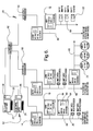
- FIG. 15 is a block diagram of a master interface constructed and connected to a lighting control system in accordance with the present invention.
- FIG. 16 is a schematic diagram of the master interface communication connection to the input and output interfaces
- FIG. 17 is a flow diagram illustrating the internal communications of the master interface
- FIG. 18 is wiring diagram of the primary and secondary communication links
- FIG. 19 is a flow diagram illustrating the input interface communications
- FIG. 20 is a flow diagram illustrating the output interface communications
- FIG. 21 is a schematic diagram of the firmware upgrade hierarchy
- FIG. 22 is a flow diagram illustrating the addressing protocol
- FIG. 23 is a schematic diagram of a prior art ambient light sensor control method.
- FIG. 24 is a schematic diagram illustrating the voltage drop phenomenon used in the present invention for creating a graphical representation.
- Lighting Control Server 12 which preferably includes both a primary control server computer 24 and a secondary/backup control server computer 26 ; Master Interface(s) 14 ; Input Occupancy/Ambient Light Interface(s) 16 ; Output Relay/Dimmer Interface(s) 18 ; Input Devices including Smart Switch Devices 20 and Ambient Light/Occupancy Sensor Devices 21 ; and, Output Relay/Dimmer Devices 22 .
- Each of these basic components contains a processor that controls its functions. Only information that is required to be known by another component in the control system is forwarded on via multi-drop and/or Ethernet communication connections.
- the lighting control server 12 is responsible for user interface functions such as inputting set points and delay settings; tying input requests to output commands; inputting switch button labels and relay descriptions; and, setting up time-clock functions.
- the primary server 12 and the secondary server 26 may include keyboards 25 and monitors 27 as diagrammatically depicted in FIG. 6 .
- the server 12 coordinates the control system 10 as a whole, through database lookups and transmission to the master interfaces 14 , the resultant of those database lookups.
- the lighting control system 10 is very modular in nature, can accommodate both small and large input/output count facilities/applications and, thus, can become very complex in structure.
- a self addressing function also referred to herein as the auto-addressing function, is provided whereby the basic components can automatically be identified and an accurate directory/database thereof can be maintained.
- the lighting control system input devices 20 , 21 are devices that directly monitor the environment of a zone.
- the input devices include smart switches 20 and occupancy/ambient light sensors 21 .
- smart switches 20 include a touch screen LCD display 28 .
- the function of the switches 20 as well as the appearance and operation of the display 28 are programmable via a program residing on the server 12 . More particularly, an initialization menu/program at the lighting control server 12 allows the user to program the function of the switch 20 , namely, the number of buttons 30 that the switch is to have.
- the buttons 30 are “soft” keys that are displayed on the LCD display 28 .
- Each of the buttons 30 is further programmable to display the description of the function of that button. That function description is automatically uploaded from the lighting control server computer 12 after the system is “setup” and “linked” by the user. The “setup” and “linking” process will be described in greater detail herein below.
- each switch 20 contains a local microcontroller 32 coupled via connectors 34 to the switch LCD display driver 36 and touch screen controller 38 .
- Microcontroller 32 is coupled to a voltage monitor 40 .
- Microcontroller 32 is also coupled via a RS-485 transceiver 44 and a connector 34 to the RS-485 multi-drop primary communication link 42 leading to its controlling-master interface 14 .
- Switches 20 are mounted in a backbox 52 with a mounting yoke 48 and spacer 50 , and can be installed in common rough in boxes (not shown) in a building wall and using a wall cover plate 46 as shown in FIG. 7 .
- the switches 20 have several unique functions. After programming by the server 12 , microcontroller 32 is responsible for maintaining the button configuration 30 and button descriptions for the switch 20 ; for the monitoring of “button presses” by a user; and, finally, for communicating any changes in status (button pressing) to its controlling master interface 14 . It is important to note, that since the smart switches 20 each have their own microcontroller 32 and touch screen LCD display 28 , they are able to communicate with a master interface 14 and display pertinent information relating to its operation to the user. As described in greater detail herein below, the smart switches 20 , as well as all other components in the control system 10 , are capable of monitoring and reporting their current state and voltage level at that component for thereby mapping/determining the components connection order and where a booster power supply may be needed. The component's current state is reported to the user both locally on the LCD display 28 and at the lighting control server 12 .
- Input Devices Occupancy/Ambient Light Devices
- occupancy/ambient light sensor input devices 21 monitor the environment in a particular zone within or around a building for light level and motion.
- occupancy/ambient light sensor 21 includes a local microcontroller 54 coupled to an occupancy/motion sensor 56 and to an ambient light sensor 58 . Similar to the smart switch 20 , microcontroller 54 is coupled to a voltage monitor 40 . Microcontroller 54 is also coupled via a RS-485 transceiver 44 and a connector 34 to the RS-485 multi-drop secondary communication link 60 leading to its controlling input occupancy/ambient light interface 16 .
- the occupancy sensor 56 monitors motion in a given zone/area.
- the ambient light sensor 58 monitors the ambient light level in the zone/area.
- the ambient light sensor 58 has three levels of sensitivity. Depending on the level of light in the monitored area, the sensor 58 will automatically adjust its sensitivity to best represent the light level. By way of example, if the light sensor 58 is placed in an area with a high level of natural ambient light (i.e. the area has a lot of windows and sky lights), it will automatically reduce its sensitivity setting to maximize the full scale of light level for that area.
- light sensor 58 is calibrated via a self calibration procedure such that, as the level of artificial lighting changes in the monitored area (i.e. as the control system 10 changes the light level from low to medium by turning on additional relays/lights in a given area) so will the sensor 58 modify its representation of the ambient light in that area.
- Each occupancy/ambient light sensor microcontroller 54 is responsible for monitoring the light sensor 58 and accurately determining the ambient light level for the zone whereat it is located, and for monitoring the occupancy sensor 56 and determining whether motion has been sensed in that same area. Additionally, the microcontroller 54 forwards this status information to its controlling input occupancy/ambient light interface 16 .
- the “on-time”, also known as the “time delay”, after motion is recognized is easily adjustable. More specifically, device 21 starts a timer after motion is sensed in the area. After a specified amount of time has passed (i.e. 30 minutes) and after not receiving any other motion indications within that specified amount of time, device 21 , in combination with the input interface 16 and master interface 14 , sends a command to the control server 12 to turn the lights off in the controlled area.
- the “on-time” or “time delay” can be sent to the device 21 microcontroller 54 via the communication network, namely, through secondary link 60 , input interface 16 , primary link 42 , master interface 14 and Ethernet link 62 , and then stored by microcontroller 54 .
- the user can thereby easily set and change, as may be needed or desired, the “on-time” or “delay time” of the input device 21 directly from the central lighting control server 12 .
- FIG. 11 illustrates a flow diagram of the communication between the occupancy/ambient light device 21 and server 12 whereby the “delay time” can be reprogrammed/changed.
- the user enters a new “delay time” at the lighting control server 12 or any other computer (not shown) that can remote link into the server 12 .
- the database of these settings which resides on the server 12 is updated (step A 2 ).
- the new “delay time” is sent through the Ethernet link 62 to the appropriate master interface 14 .
- the master interface 14 receives and then forwards the requested change through the primary link 42 to the appropriate input interface 16 (step A 4 ).
- step A 5 the input interface 16 then forwards the change through the secondary link 60 to all of the appropriate input devices 21 under its control.
- Each affected device 21 then updates and stores the new “delay time” and confirms the change was made back to its controlling input interface 16 (step A 6 ).
- step A 7 it is noted in step A 7 that, if any of the affected devices 21 does not respond with a confirming message, an error message is sent to and logged on the input interface LCD 64 and the error message is also sent back through the master interface 14 to the server 12 for logging. It is noted that the communications between the control system components is more specifically described herein below.
- the occupancy/ambient light device 21 is capable of communicating its current state, and the voltage level at that component, back to the lighting control server 12 and to its controlling input occupancy/ambient light interface 16 .
- the device's 21 current state and voltage level is reported to the user both at the input interface LCD 64 of the input interface 16 which is typically located generally nearby the device 21 , as well as at the lighting control server 12 .
- occupancy/ambient light devices 21 do not each have their own touch screen LCD display as this would greatly increase their cost and physical size. Additionally, the occupancy/ambient light devices 21 , are typically located and mounted up high on a wall or on the ceiling and, therefore, a touch screen and/or a LCD display mounted directly thereon would not be practically useable and would unnecessarily add to the cost. Instead, occupancy/ambient light devices 21 are connected via a multi-drop secondary communication link 60 to a controlling input interface 16 having a LCD 64 and whereat relevant information in connection with the devices 21 is displayed. It is noted that a total of sixteen devices 21 are allowed to be connected to each interface 16 and that all information in connection with all sixteen devices 21 is displayed on the controlling interface 16 . In this manner, the user/installer is provided with a means for getting local/nearby setup and status information of each device 21 while the system cost is minimized.
- the occupancy/ambient light devices 21 contain an ambient light sensor 58 that is, as described herein above, capable of self adjusting its sensitivity setting, it is possible to fairly easily identify the device 21 and the input interface 16 and, thus, on the control system 10 . That is, pointing a flashlight or otherwise providing another light source at the device sensor 58 will cause a spike in the light intensity reading of the device sensor 58 . As further described herein below, using this phenomenon/procedure, the spike can be observed at the controlling input interface 16 LCD 64 for setting up and identifying the input device 21 on the multi-drop secondary link 60 .
- the input occupancy/ambient light interface 16 are used to collect, display locally, and pass on to the controlling master interface 14 the status of the occupancy/ambient light devices 21 in one or several zones.
- a block diagram of a typical input occupancy/ambient light interface 16 is shown in FIG. 12 .
- Each input interface 16 contains a local microcontroller 66 coupled to a LCD display and controller 64 and a touch screen controller 68 .
- Microcontroller 66 is coupled to a voltage monitor 40 .
- Microcontroller 66 is coupled via a RS-485 transceiver 44 and a connector 34 to the RS-485 multi-drop primary communication link 42 leading to its controlling master interface 14 .
- Microcontroller 66 is also coupled via a RS-485 transceiver 44 and a connector 34 to the RS-485 multi-drop secondary communication link 60 leading to up to sixteen occupancy/ambient light devices 21 .
- an input interface 16 will be installed and reside locally/nearby the area where the occupancy/ambient light devices 21 it interfaces with, are installed.
- the physical geographic location of the interface 16 is not a requirement due to electrical constraints (i.e. cable length or data transmission rate) but, rather, it is a practical issue when setting up the connected sensors/devices 21 which it controls.
- the occupancy/ambient light devices 21 are “daisy-chained” from device to device with a maximum of sixteen sensors/devices 21 per input interface 16 . Each device 21 is “assigned” a unique address from the server 12 via the controlling master interface 14 and input interface 16 .
- a particular zone or area requires several sensors/devices 21 to adequately cover the square footage or shape thereof, that grouping information is passed on to and “grouped” at the lighting control server 12 . This allows the sensors/devices 21 in a large or oddly shaped room to act and/or be treated as one common sensor/device 21 .
- the sensors/devices 21 individually or collectively control a zone or area within or outside the controlled facility.
- a zone may be an office, a hallway, a conference room, a lobby, a parking lot or any other area that would be considered an area within or outside a building.
- Each zone may contain multiple levels of lighting, but should typically operate as a unit.
- a conference room may contain separate control levels for each of a can light circuit, a chandelier circuit, and a general fluorescent lighting circuit, but the general ambient light level for the entire conference room and or motion within the conference room should typically be represented as one area/zone. Any motion within that room or zone will trigger an event that is taken care of pursuant to the desired programmed response at the server 12 .
- the sensors/devices 21 , input interfaces 16 , master interfaces 14 and lighting control server 12 all work together to control the lighting in a given area/zone. If a sensor/device 21 recognizes movement in a given area, that sensor/device 21 will forward that event to its controlling input interface 16 . The input interface then forwards that event on to the lighting control server 12 through the applicable master interface 14 . The lighting control server 12 then looks up in its database what to do when that event is triggered. It also checks all other sensors/devices 21 that are “grouped” with this sensor/device 21 to check their status. The following actions and results are preformed based on the quantity of sensors/devices 21 in a given area or zone:
- sensors/devices 21 which are controlled by multiple input interfaces 16 can also be “grouped” together. Accordingly, the installer need not know or otherwise keep track of how the system is going to be setup (or grouped) when installing/wiring the system. Additionally, the lighting control server 12 has the ability to “verify” the status of a given zone/area before it triggers an event. For example, if the lighting control server 12 were to miss an off event from one of the occupancy/ambient light devices 21 , then the “state” of that zone would be incorrectly represented at the server 12 .
- the server 12 can verify the state of each of the grouped sensors/devices 21 prior to initiating an ON or OFF command.
- the input interfaces 16 include a local LCD display 64 , the “status” of each sensor/device 21 can be identified and viewed locally/nearby, as the sensors/devices 21 see it, of the applicable room/zone. Additionally, the input interfaces 16 simplify the wiring/installation of the up to sixteen sensors/devices 21 within a room or across several rooms since the devices 21 can be wired in any order without regard to location or cable drop point.
- FIG. 13 shows a block diagram of typical output relay/dimmer devices 22 and how they connect with the output relay/dimmer interfaces 18 .
- Output devices 22 can include lighting control relays (single pole and two-pole) and dimmers (incandescent/LED/fluorescent).
- Each such output device 22 includes a local microcontroller 70 which is coupled to and controls the on and off status of the relay/dimmer and utilizes a combination of a mechanical relay and electronic control to turn on and off the circuit to the load.
- Microcontroller 70 is also coupled via a RS-485 transceiver 44 and a RS-485 multi-drop secondary communication link 60 directly to the output interface 18 .
- Microcontroller 70 is capable of determining the location/address whereat the device 22 is plugged into the output interface 18 , and to communicate this and other information such as the device 22 characteristics (i.e. a single or double pole relay) to the output interface 18 .
- Devices 22 which function as lighting control relays, like other devices 22 , each contain a local microcontroller and is connected directly to an output interface 18 . Like other devices 22 , it communicates directly with the output interfaces 18 via a communication link 60 which is imprinted directly onto the output interface 18 circuit board. Additionally, the devices/relays 22 are able to determine the location whereat they are plugged into the output interface 18 . The devices/relays 22 are able to use this information and communicate it to the server through the output interface 18 and master interface 14 (i.e. whether it is a single or double pole relay and where it is located in the control system/communication network).
- the devices/relays 22 are capable of being configured as either a single pole device (for 120V and 277V loads) or a double pole device for (208V or 480V loads).
- a double pole configuration is provided by plugging in a second relay module into the first.
- the microcontroller 70 of the controlling module/device 22 acknowledges the additional pole (module/device) and automatically forwards this information onto the output interface 18 whereby this information is then passed on through the master interface 14 to the lighting control server 12 .
- the microcontroller 70 controls the on and off status of the device/relay 22 .
- the device/relay 22 utilizes a combination of a mechanical relay and an electronic control to turn on and off the circuit to the load.
- the device/relay 22 is a microcontroller based controller wherein the microcontroller determines and communicates its associated relay's location, the type of relay it is to the server 12 , and wherein it efficiently controls the connected load.
- the microcontroller 70 thereof is also capable of detecting and communication error information back to the server 12 through it controlling output interface 18 and master interface 14 .
- Devices 22 which function as incandescent lighting dimmers, like the on/off relays discussed herein above, each have a local microcontroller 70 .
- the devices/dimmers 22 have the same physical dimension as the lighting control devices/relays 22 . Additionally they have the same pin connections for connecting and communicating via a RS-485 multi-drop secondary communication link 60 to the output interface 18 . Thus they are interchangeable with the devices/relays 22 and are able to communicate the same/similar information back and forth with the relay interfaces 18 .
- the devices/dimmers 22 are capable of reducing the power output to the load (light). They do this by first receiving a command of “light level” from the output interface 18 in lieu of an on/off command.
- the incandescent lighting devices/dimmers 22 communicate the same or similar information back and forth to the server 12 through the output interface 18 and master interface 14 (location, type and status, etc.).
- Devices 22 which function as LED/fluorescent lighting dimmers are also similar to the 2-pole lighting control devices/relays 22 described herein above. They use the same second module as the 2 nd pole of the 2-pole lighting control device/relay 22 . However, the second pole is used to turn on/off the required switched circuit to the dimming ballast. The dimmed output from the dimmer module is used to provide the dimmed circuit to the dimming ballast of the LED or fluorescent light fixture. When the second pole module is plugged into the dimmer it automatically recognizes this configuration and now represents itself as an LED/fluorescent lighting dimmer in lieu of an incandescent lighting dimmer to the relay interface. All other functions of this dimmer are the same as the incandescent lighting device/dimmer 22 described herein above.
- Output relay/dimmer interfaces 18 are generally the output equivalent to the input interfaces 16 .
- the output interfaces 18 are used to control the above described devices 22 (relays and dimmers). Like the input interfaces 16 , the output interfaces 18 communicate with the master interfaces 14 .
- the output interfaces 18 control (turn on, off or dim as appropriate) the output devices 12 which are connected to them.
- the output interfaces 18 receive commands via a primary communication link 42 from the master interface 14 as to what devices 22 (relays or dimmers) are to be controlled and to what level (on, off or dimmer level). Additionally, the output interfaces 18 forward information from each of the connected devices 22 (relays and/or dimmers) back to the master interface 14 . This information can include the characteristics of the devices 22 connected at each of its ports/connections, and the current status of each such device 22 (if it is on, off or to what level it is dimmed at).
- FIG. 14 A block diagram of a typical output relay/dimmer interface 18 is shown in FIG. 14 . Similar to the input interfaces 16 , the output interfaces 18 are provided with a local LCD 72 and touch screen 74 for indication and local control of the aforementioned status information. This allows the user and/or installer to view locally and directly such information and status thereof.
- the output interfaces 18 also contain a local microcontroller 76 which is coupled to the LCD display and controller 72 and the touch screen controller 74 .
- Microcontroller 76 is coupled to a voltage monitor 40 .
- Microcontroller 76 is coupled via a RS-485 transceiver 44 and a connector 34 to the RS-485 multi-drop primary communication link 42 leading to its controlling master interface 14 .
- Microcontroller 76 is also coupled via a RS-485 transceiver 44 and to the RS-485 multi-drop secondary communication link 60 to the pin sockets/connectors 78 whereby up to eight devices 22 (relays and/or dimmers) can be connected as depicted in FIG. 13 .
- the LCD 72 also serves as a local circuit directory for the user during installation and/or for maintenance purposes.
- This directory includes a cross reference between the connected devices/relays 22 and a description of the controlled load (i.e. “Conference Room Can Lights”).
- This directory can be of significant assistance and can significantly decrease time and costs when troubleshooting malfunctions and making future modifications. Since all of this information is collected at the lighting control server 12 , it can easily be forwarded on to the local LCD display 72 of the output interface 18 . All additions and/or changes of the devices 12 are handled automatically at the server 12 and each of the descriptions of the loads for which a connected device 12 (relay or dimmer) is connected is then displayed by default on the LCD display 72 . Should the user want to see different information (i.e. status info) at the local LCD display 72 , they can merely press one of the local menu sequence buttons on the touch screen 74 .
- status info i.e. status info
- Master interfaces 14 are used to collect the status changes in any zone, via a primary communication link 42 , from the input occupancy/ambient interfaces 16 and smart switches 20 , and to command changes to the output interfaces 18 , also via the primary communication link 42 .
- Each of the interfaces, whether input or output, are connected in a daisy-chain fashion to the primary communication cable/link 42 .
- This communication cable/link 42 also acts as a power cable and provides power to each of the connected components 16 , 18 and 20 .
- the voltage level at each component is monitored for thereby mapping/determining the components connection order and where a booster power supply may be needed.
- FIG. 16 diagrammatically shows a typical connection scheme of this portion of the control system 10 .
- an Ethernet connection/link 62 connects master interface 14 to the server 12 .
- FIG. 15 A block diagram of the master interface 14 is shown in FIG. 15 .
- Master interface 14 has two processors/microcontrollers, namely, an Ethernet processor 82 and a master processor 84 .
- Processors 82 , 84 are connected to one another with a dedicated serial communication link 86 .
- Ethernet microcontroller 82 is coupled via an Ethernet connector 80 and the Ethernet link 62 to the server 12 .
- the master microcontroller 84 is coupled via a RS-485 transceiver 44 and a connector 34 to the RS-485 multi-drop primary communication link 42 leading to the interfaces 16 , 18 and smart switches 20 .
- the master microcontroller 84 is also coupled to a LCD display and controller 88 as well as a touch screen controller 90 .
- Master microcontroller 84 is coupled to a voltage monitor 40 .
- the master interfaces 14 are a key part of the control system 10 and make the control system modular. Master interfaces 14 are used to collect and distribute information back and forth from the interfaces 14 , 18 and smart switches 20 to the lighting control server 12 .
- the master interfaces 14 perform several key functions in the control system 10 . First, as more fully discussed herein below, they act as interpreters between the building's Ethernet (data) network and the communication network of input and output interfaces 14 , 16 and smart switches 20 . Second, the master interfaces 14 act as collection managers. For example, when several commands are received from several of the input or output interfaces 16 , 18 or smart switches 20 (i.e. button being pushed), the master interface 14 collects that information and packets it in an efficient manner to be sent to the lighting control server 12 .
- master interfaces 14 maintain a local data table of all of the connected components 14 , 16 , 18 , 20 and 21 for determining system health and status. Like the input and output interfaces 16 and 18 , it too has a local LCD display 88 and touch screen 90 for local feedback to the user during installation and troubleshooting.
- the control system 10 can virtually include an unlimited number of input and output components 14 , 16 , 18 , 20 and 21 . Since the number of master interfaces 14 is only limited by the limits of the Ethernet network, through the use of local microcontrollers for collection and efficient packaging of communicated information, an almost unlimited number of input and output points can be realized. This structure allows for an efficient and cost effective solution for both small scale and large scale applications.
- the lighting control server 12 serves two basic functions. First, the lighting control server 12 acts as a database server—a function that a computer does very well. When a master interface 14 (via Ethernet communication) sends an event change or group of event changes, from one of the zones which it is controlling, to the lighting control server 12 , the server 12 looks up in a database (that resides on the lighting control server 12 ) what to do with that event. The server 12 then queries its database for the output event or events that is/are to be performed when the applicable input event is encountered. The server 12 then organizes a string of commands to be sent to the master interface(s) 14 that control the applicable output interface(s) 18 that control the output event (relay turning on or off, etc.).
- a second function of the lighting control server 12 is to act as a direct and integral interface of the lighting control system 10 and the user programmer.
- the key point here is that the server 12 it is an integral part of the lighting control system; therefore, it acts as a simple and seamless interface with the lighting control system 10 .
- the function of programming the system is handled by a software user interface that resides on the server 12 . This interface can access the database (that also resides on the server 12 ) directly. This greatly simplifies the programming of the control system 10 . No uploads and downloads are required between the lighting control system 10 and the programming computer/server 12 as they are the same device accessing the same database directly.
- the commands to and from the master interfaces 14 are administered by a “Service” running on the lighting control server 12 . This service runs independent and continuously on that server 12 as long as it is powered up.
- an additional secondary/backup server 26 can be added and coordinated with the primary lighting control server 24 (this would provide a level of redundancy in the system should that be a concern).
- the server 12 can also be accessed from any other computer (with the proper security privileges) on the building's Ethernet network 62 via common remote interfaces available (such as Microsoft's Remote Desktop or a client application).
- This allows the server 12 to physically reside anywhere in the building and to be accessed at any physical location in the building with a computer and proper security privileges. For example, this would allow the lighting control server to reside in the IT department's main distribution frame (MDF).
- MDF main distribution frame
- a computer in the maintenance department could be granted privileges to access the server 12 for programming changes; or, a computer in the area to be controlled can be used for adjustments to the lighting level in a particular area.
- the flexibility of the lighting control server 12 being a node on the building's Ethernet network 62 allows all of the above described functionality and various other options for user interface as will become evident to one skilled in the art.
- the above described basic six components 12 , 14 , 16 , 18 , 20 and 21 are programmed and work together as further described herein below so as to provide to a centralized building lighting control system 10 .
- the overall or central control scheme is first herein after described, namely, how the components 12 , 14 , 16 , 18 , 20 and 21 talk to each other (communicate); how they update their firmware; and, finally, what the significance of the local LCD touch screen displays have in the system makeup.
- control system 10 has three levels of communication with the master interface 14 being the center thereof.
- the master interface 14 has two processors 82 , 84 that are connected directly to one another with a dedicated serial communication link 86 .
- the Ethernet processor 82 is dedicated to communications with the Ethernet network 62 to the lighting control server 12 .
- As data becomes available (either incoming from the Ethernet network 62 or outgoing from the master processor 84 ) the data is loaded in one of two circular buffers. Data coming in is loaded in one of the buffers; data going out is loaded in the other buffer.
- the master processor 84 is used to communicate with the input and output interfaces 16 , 18 and the smart switches 20 on the primary RS-485 multi-drop communication link 42 .
- the communication between the lighting control server 12 and the master interfaces 14 is done via standard Ethernet TCP/IP communication protocols. Both of the subsequent levels of communication (the primary communication link 42 and secondary communication link 60 ) utilize a RS-485 multi-drop, addressable communication protocol.
- FIG. 17 shows a flow diagram of how the master interface 14 collects, organizes and distributes information collected from both the Ethernet network 62 and the primary RS-485 link 42 .
- the first level of communication is between the lighting control server 12 and the master interface 14 . It is first important to understand how the master interface 14 connects with the lighting control server 12 .
- a master interface 14 When connected to the building's computer (data) Ethernet network 62 , a master interface 14 is programmed to and will obtain an IP address automatically from the data network's controller (i.e. router).
- the lighting control server 12 is connected to the building's computer (data) Ethernet network 62 , it will also obtain an IP address from the building's data network controller (i.e. router).
- the master interface 14 After the master interface 14 has obtained its IP address it is programmed to and will then poll or broadcast its initialization information packet to the system for a lighting control server 12 .
- the lighting control server 12 has a unique identifying code to distinguish it from other connected devices.
- the master interface initialization information packet includes its IP address. When the lighting control server 12 responds, it forwards its IP address back to the master interface. Accordingly, two-way communication is thereby established (typically within milliseconds) between the server 12 and master interface 14 . Should power go down or a loss of IP address occur for any reason from one or all of the master interfaces 14 and/or lighting control server 12 , the same procedure will be re-initiated to re-establish communications automatically.
- each master interface 14 is programmed to and is able to present the automatically connected IP address should the user need to troubleshoot connection issues.
- the procedure listed above allows the master interface and lighting control server to connect automatically in a DHCP environment. If a static IP scheme is employed at the facility where the lighting control system is installed the installer can simply set the IP address of each master interface and the lighting control server via the LCD touchscreens and the graphical user interface, respectively.
- the next level of communications is between the master interfaces 14 and the smart switches 20 , the input interfaces 16 and the output interfaces 18 and is accomplished with an RS-485, multi-drop, secondary link 60 .
- the master interface is programmed to take the lead in this communication connection.
- the master interface 14 In order for the components 16 , 18 and 20 to communicate with each other, the master interface 14 first assigns an address to each as more fully described herein below in the Auto-Addressing section. This address is automatically cross-linked with an ID that is established at the lighting control server. The cross-linked ID is what is displayed and used for setup and installation of the system. After the interfaces 16 , 18 and switches 20 are assigned an address, they are programmed to and capable of communicating with the master interface 14 . The master interface 14 initiates all communication at this level.
- the master interface 14 polls each interface 16 , 18 and switches, one after another, until it reaches the last connected address. It then returns to the first address under its command and starts the process over. In between each such polling cycle of the interfaces 16 , 18 and smart switches 20 , the master interface processor 82 reads its incoming Ethernet circular buffer and writes to its outgoing Ethernet circular buffer as appropriate.
- the lowest level of communication is the secondary RS-485, multi drop communication link 60 .
- the input and output interfaces 16 , 18 contain just one processor. Each of these processors has two serial ports, one to talk to each of the primary and secondary RS-485 links 42 , 60 .
- FIG. 18 shows a typical input and/or output interface 16 , 18 communication connection scheme/link 60 .
- the secondary communication link 60 is responsible for communications between the respective input or output interface 16 , 18 and its corresponding occupancy/ambient light sensor devices 21 and output relays and/or dimmers devices 22 .
- FIGS. 19 and 20 show and describe the operational/program flow diagrams for the communication methods of the input and output interfaces 16 , 18 respectively.
- the control system 10 includes an updating method for allowing firmware/software features to be added and “bugs” worked out of the firmware for all components 12 , 14 , 16 , 18 and 20 in the system.
- the updating method/scheme is needed because the control system 10 , as described herein above, is modular. Additionally, because the control system 10 is expandable, and because of the likely hood of expansion is probable, the updating method for firmware upgrade (or downgrade) is seamless and automatic.
- the new relay devices 22 and output interfaces 18 may not communicate all commands correctly because of the different levels/versions of firmware installed on each.
- the updating method includes a “trickle down” firmware modification method/scheme.
- FIG. 21 shows how the firmware for each level is stored.
- the subsequent/lower levels i.e. the input interface 16 is a subsequent/lower level to the master interface 14
- FIG. 21 shows how the firmware for each level is stored.
- the subsequent/lower levels i.e. the input interface 16 is a subsequent/lower level to the master interface 14
- the lower level component/device is queried by the higher level component/device.
- the initialization and communications information packets also include the firmware number/version identification. If the firmware versions do not match, then the newly connected component/device sets a location in EEPROM and then resets itself. Upon a reset, each microcontroller enters its boot-loader function/process. In the boot-loader function, the component/device checks to see if the EEPROM code is set. If so, it erases the resident firmware program and requests the firmware program that is imaged on the higher level component/device to which it is connected. The higher level component/device then downloads the applicable firmware to the newly connected lower level component/device. Upon receipt of the firmware from the higher lever component the newly connected component/device resets its EERPOM location and resets itself again.
- the boot-loader on the newly connected component/device recognizes that the change in EEPROM location and immediately jumps to the newly loaded firmware program. Normal operation then resumes. This same technique applies to all components 16 , 18 and 20 and devices 21 , 21 and levels of the control system 10 .
- the new firmware is downloaded through the Ethernet connection to the master interface 14 via a menu selection of the graphical user interface program residing on the lighting control server 12 .
- the boot-loader of the master interface 14 finishes updating its firmware and storing the subsequent firmware images, the lower lever/order components will automatically propagate the new revisions throughout the system using the method described above.
- Each interface whether it be a master interface 14 , input interface 16 , an output interface 18 or smart switch 20 , as described herein above, has its own LCD touch screen display.
- the LCD displays are used for many functions including communicating to the user/installer interface/switch status, communication status, connection status and, in the case of the output interface 18 , the circuit (switch-leg) descriptions.
- Switches 20 as described herein above, also display button configurations and button labels (descriptions).
- the significance of the local LCD displays is also evident with the smart switches 20 .
- the user With the LCD display 28 on the switch 20 , the user is able to coordinate buttons 30 configurations as desired through interactive menus on the lighting control server 12 .
- the switch 20 automatically uploads configuration information and descriptions for each of its buttons 30 after a description is entered or updates are made. This eliminates the need for engraved or worse yet unmarked face plates describing each button.
- a significant advantage of the control system 10 is its ability to self address each of the components 12 , 14 , 16 , 18 , 20 , 21 and 22 . This is made possible because, as described herein above, each component includes a microcontroller.
- Each microcontroller contains a limited amount of non-volatile memory (EERPOM memory) whereat an auto addressing program/process is able to store status information for coordinating and maintaining an address for itself and the rest of the system components. That is, a primary function of each of the microcontrollers 32 , 54 , 66 , 70 , 76 , 82 and 84 is to coordinate and maintain an address protocol for the control system 10 .
- EERPOM memory non-volatile memory
- the lighting control server 12 resides over the master interfaces 14 ; the master interfaces reside over the multi-function smart switches 20 , the output interfaces 18 and input interfaces 16 ; the output interfaces reside over the relays and dimmers devices 22 ; and, the input interfaces 16 reside over the occupancy/ambient light sensor devices 21 .
- This topology allows for the higher order device (i.e. master interfaces 14 ) to communicate directly with the lower order devices (i.e. input/output interfaces 16 , 18 ), and also allows the higher order components to address and maintain a table of connected components/devices for the lower order devices.
- the method of addressing may differ slightly for the type of component/device (input components/devices vs. output components/devices) the overall method/scheme is generally the same.
- the local LCD displays 68 , 72 and 28 (located on each of the input or output interfaces 16 , 18 and switches 20 ) perform at least two functions during the self-addressing and setup process. First, it steps the user through the process as the new component/device is addressed. That is, each step is displayed on the applicable LCD so the user is aware of what is transpiring. For example, when a new smart switch 20 is first connected via the primary link 42 with a master interface 14 , the switch LCD 28 displays a message indicating that the switch “Has not been setup/addressed” and presents/displays a “setup button” 30 for the user/installer to press to begin setup/addressing process.
- the switch LCD 28 displays/presents a bar graph showing the progression of the setup/addressing process.
- the switch is programmed to and checks with the master interface for firmware compatibility/equality. If the firmware on the switch 20 and master interface do not match, then a request and subsequent transfer of firmware is performed between the two components as described herein above. As also described herein above, this is possible because the firmware for the switch 20 resides in memory as an image on the master interface 14 .
- the firmware coordination/updating process can take several seconds and the LCD display 28 again displays/presents a bar graph representing the status of the firmware coordination/update.
- a second function of the local LCD displays 68 , 72 and 28 during setup/addressing is to allow the user/installer to identify the component/device for “linking”.
- Linking is performed, as more fully described herein below, at the server 12 to allow the real/physical component/device to function the same as the virtual component/device that is programmed and visible on the monitor at the lighting control server.
- the component/device ID (cross-referenced from the device's address) is displayed on the local LCD displays 68 , 72 and 28 for easy viewing by the user/installer.
- Each component/device includes a physical “setup button” or one is programmed and displayed on its LCD (or on its controlling interface 16 , 18 LCD) via its respective touch screen controller 38 , 68 , 74 , 90 as, for example, described herein above in connection with the smart switches 20 .
- the master interface propositions the new/replacement input/output interface 16 , 18 and initializes the set procedure and, when the setup button is pressed on or in connection with the newly added component/device, the installer is also prompted if the new/replacement interface 16 , 18 should be installed using the same ID and corresponding address as the old component/device. Accordingly, the installer can elect to use the same ID/address of the old missing component/device or request a new ID/address. If the existing but unused ID/address is selected, all previously programmed and linked interactions with the old component/device from the server 12 will now apply to the new/replacement component/device.
- the lighting control server 12 is programmed to and will display the virtual previously linked icon of that component/device with a red “X” through it. Accordingly, the user viewing the server 12 monitor will know that that previously linked component/device is no longer being recognized and can take corrective measures as needed. All other previously programmed functions of the control system 10 will still be available, but that component/device will not be active since it is “missing”.
- a command from the server 12 is sent to the applicable controlling interfaces 14 , 16 , 18 to remove that component/device from their respective tables. If the component/device is still available (if it is still physically connected to the control system network) the component/device will again regain the 65 address ID and will be become ready for a “new installation” setup button press.
- the setup and addressing protocol and method/scheme between the master interfaces 14 and their connected input/output interfaces 16 , 18 is the same as that described above between the master interface 14 and the smart switches 20 .
- the ambient/occupancy sensor devices 21 do not contain a local LCD.
- devices 21 include a light sensor 58 which, in conjunction with a flashlight or other similar light source, can be used to assign an address thereto.
- the installer/user In the procedure for setting up an ambient/occupancy sensor device 21 , the installer/user first selects the input point on the controlling input interface 16 by pressing a soft key/“setup button” on the local touch-screen display 66 , 68 representing the input device 21 to be setup. It is noted that up to sixteen devices 21 can be connected to one input interface 16 , and the status of all sixteen devices 21 is displayed on their controlling interface LCD screen 66 . The displayed status includes an indication showing if the device 21 is setup and the address thereof or, if it is not yet set up, an available “connection point/button”. To set up and address a device 21 , the installer selects a desired connection point and presses the “connection point/button” on the touch-screen display 66 , 68 .
- the interface 16 then causes all of the devices 21 that are physically connected (wired) to it but are not yet addressed or setup to flash an LED light which is physically located on the devices 21 .
- the installer can, thus, physically see the devices 21 which are not yet addressed or setup.
- the device 21 is programmed to and will recognize the spike in its light level and request that connection point address from its input interface 16 . All devices 21 under that interface 16 will then stop blinking their LED's until another setup request is given by pressing another available “connection point/button” at the input interface 16 .
- a device 16 Once a device 16 has received its address, it is programmed to and then goes through the procedure described herein above to coordinate and/or update or obtain the compatible version of firmware. Should the user/installer want to see the address of a device 21 at a later date, the input interface 16 can be placed in a “check address mode” by pressing a soft button of the controlling interface LCD 66 , 68 whereby, by pointing a flashlight at a device light sensor 58 , both the device LED will be caused to blink and the input connection point of the input interface 16 will display indication thereof.
- the setup and addressing protocol and method/scheme between the output interfaces 18 and the output devices 22 is substantially the same as between the master interface 14 to input/output interface 16 , 18 in regards to the deletion or loss of a device 22 .
- the creation/assignment of a device 22 address is also similar, except that the output relay/dimmer device 22 is physically plugged into a specific port/pin socket 78 on the output interface 18 .
- the address which is assigned to the device 22 is the port/pin socket 78 to which it is attached.
- the addresses are assigned by the device 22 being plugged into an output interface pin socket 78 and a fixed code on three of the connection pins/wires between the device 22 and the output interface 18 .
- the three pins/wires use a binary code to represent the pin socket 78 location of the device 22 .
- FIG. 13 shows the address/access code for each pin socket 78 location whereat an output relay/dimmer device 22 can be plugged into and connected to the output interface 18 .
- the output interface 18 continually scans each connection points 78 to verify whether or not a device 22 is present. After the address of a device 22 is established, the output interface is programmed to and requests additional information from the output device 22 , including the type of output device it is (single pole relay, two pole relay, incandescent dimmer, or fluorescent dimmer).
- the output interface 18 can then use this information to update its table of connected devices 22 and pass the device information to its controlling master interface 14 whereat the maser interface 14 updates its table of connected components/devices.
- the master interface then passes on the information to the server 12 for updating the connected components/devices table on the server 12 .
- the highest level of communication is between the master interface 14 and the lighting control server 12 .
- This communication is via standard Ethernet protocols and standard network switches 92 , thus, no special auto-addressing procedures are required.
- This communication is setup using standard TCP/IP protocols.
- the lighting control server 12 does assign each master interface 12 and ID so the user is able to distinguish it when “linking” components of the system, but this ID is independent from its IP address that is assigned by the network's router.
- the “missing device” and device deletion methods described above are used here also with the master interfaces 14 . Database tables on the server 12 are updated and modified for the master interfaces 14 like any other device in the system.
- Each component/device 14 , 16 , 18 , 20 , 21 and 22 is identified by a nomenclature which uses the address of its higher level/controlling components. Because a master interface 14 is the highest order component in the control system 10 requiring addressing, when it is added to the control system, it obtains its cross-referenced ID from the lighting control server 12 . When the lighting control server 12 recognizes a new master interface, it assigns it an ID of “M”+the next available number (i.e. M1, M2, M3, etc.). The master interface 14 is responsible for assigning the ID of its lower lever connected components/devices.
- an output (Relay) interface 18 would have an address ID like M1_RI3.
- M1 represents the ID of its controlling master interface
- RI relay interface
- 3 represents the address number of the output interface 18 .
- up to sixty components/devices are possible on a primary communication link 42 .
- the following table illustrates several examples of the addressing nomenclature of control system components:
- each component is used at the server 12 to “represent” that component in the control system.
- a “virtual” component/device is first established. For example, if a new switch 20 is to be added to the control system, the user would create a new virtual switch using the graphical interface program on the server 12 . The configuration of the switch would first be selected, i.e. 2 button, 3 button, etc. Then a description would be provided for each button 30 (this description will appear on the physical switch LCD 28 buttons 30 ). After the virtual switch is established, it can be “dropped” into a group of virtual devices 22 that it is to control.
- This group of devices can be one or more of a collection of switches, relays, time-clocks, dimmers, etc. that are to work together in controlling or lighting the inside or outside the building/facility.
- This “dropping” of each component into each group of devices is done by a standard drag and drop procedure common to many software applications (similar to moving a file between folders on a hard drive). Accordingly, the items that are grouped can be coordinated to control the components of that group.
- a zone or group
- the “time clock” can be “virtual” in the sense that it is programmed to operate the relays based on the server clock
- the user/installer can assign the operation of various relay devices 22 to various buttons 30 of the two switches 20 .
- the user can assign the relay devices to be overridden by the virtual time clock which has been established and is part of that group. Since all of the components in that group represent a small sub-system of the larger control system 10 , the user can easily create complex/desired control schemes for that group. By combining this feature with the ability for each component/device to communicate with one another, complicated control schemes are simply a matter of dragging and dropping between components.
- the user/installer wants to have the lights go to an AUTO mode every morning at 7:30 AM (in the AUTO mode, the lights should turn on only when an occupant is in the room); the level of lighting is to be determined by the ambient light sensor 58 of the ambient/occupancy device 21 ; and, the user/occupant should have the ability to go to a fixed level (i.e. low level) when a “LOW LEVEL” button 30 is pressed on the local smart switch 20 .
- a fixed level i.e. low level
- the programmer In order for the “LOW LEVEL” function to operate when the corresponding button is pressed the programmer simply drags the relays that are to turn on or off into the appropriate boxes labeled “On” and “Off” after highlighting the “LOW LEVEL” button of the Virtual Switch”. Additionally, the “AUTO MODE” function is dragged into the “Off” box telling the system to turn off the AUTO MODE function (i.e. to stop controlling the lights by reference to ambient light level and motion). Another requirement of the example was to have the lights of the affected group go into an AUTO MODE at 7:30 AM. This is done by opening up the time-clock that represents that function of the group and dragging the AUTO MODE function into the “On” Box.
- each device can be dragged and dropped into individual or multiple groups.
- An example of this is with our 7:30 AM time-clock. That same time-clock can be assigned to several groups if desired and can perform different functions in each group should that be desired (i.e. it may tell all interior zones to go to AUTO MODE and tell all exterior lights to turn off).
- the developing of “virtual devices” and “grouping” of those devices allows the programmer to “pre-setup” the system as a whole prior to having the physical components/devices installed or setup on the system.
- the method to “link” the physical component/device to the virtual device uses the same procedure as that described above. It is noted that when a physical component/device is setup on the system, the lighting control server generates a unique ID for it that is displayed on the server until it is linked on the server 12 . That ID is also available at any time on the local component LCD display by pressing and holding a spot anywhere on the touch-screen for several seconds. The user can use the displayed ID's of unlinked devices on the server and “link” them to a desired virtual device.
- Energy conservation is a motivating factor for incorporating a lighting control system in a facility. It is desirable to provide lighting only when needed and then, preferably, only at an intensity sufficient for the intended use. It is also desirable to use natural/ambient light when available, and thereby decrease the artificial light being provided from light fixtures and, hence, the power consumption.
- a deficiency with existing lighting control systems is their ability to accurately represent the steady state light conditions of a room or area.
- Some existing lighting control systems use ambient light sensors in an attempt to conserve energy.
- the ambient light sensors as they are used in existing lighting control systems, are unable to correctly/accurately represent the light level in the room or area as they do not perform a “profile” for the controlled area/room.
- the setup procedure for the light sensors is tedious and inaccurate.
- FIG. 23 A prior art/existing method of using light sensors is depicted in FIG. 23 .
- the full range of the sensor is used to represent the light level in the room (not the actual range of light conditions of the room being detected).
- Several user defined “on” set-points and “off” set-points are programmed into the system wherein the differential between each “on” set-point and “off” set-point is small. A small differential is used so as to reduce the likelihood of cycling of the controlling relay around the on/off set-point.
- the user must monitor the light level in the controlled areas/rooms to determine all of the on and off set points and how they correspond to the desired light level for the area/room for differing levels of natural light. If this was required for only one area in a building, this may not be a difficult task, but when it is required throughout the facility with the windows in rooms facing different directions, the task can be daunting. Accordingly, set up requires highly experiences installers and is typically time consuming and costly. The end result is inaccurate control of light levels due to the lack of time or experience by the installers. Another problem with the prior art/existing control systems is the inability to accurately measure the natural (or ambient) light level without influence from artificial light sources (i.e. the light fixtures that are being turned on and off in the area being sensed/monitored). How the lights in the controlled room affect the light level with varying conditions can make the success of calibrating this type of system borderline effective and frustrating.
- artificial light sources i.e. the light fixtures that are being turned on and off in the area being sensed/monitored
- the present light control system 10 overcomes the disadvantages of the prior systems by developing a light profile, through the use of its input occupancy/ambient light interface 16 , for the light level in the area which the sensors are representing. This light profile is then used as the basis for the desired control scheme.
- a dynamic profile is generated using the steady-state light level as the reference point for control.
- the steady-state light level is the actual ambient light level in a particular area with no influence by artificial lighting.
- the steady-state light level will change as the amount of natural (ambient) light changes, but that is insignificant when determining a profile for the controlled area.
- the ambient light level would be the lighting level in the room without influence from the light fixtures in that room.
- each level of lighting must be introduced into the equation and its resultant change in light level stored as a reference point for each added level of light (i.e. a relay is turned on, the light level is read by the ambient light sensor in that area, and the change in light level is stored with the relay information in a database resident on the lighting control server.
- the microcontrollers on both the ambient light sensors 58 , the input interface 16 , the output interfaces and the relays/dimmers are coordinated to work together with the lighting control server 12 to develop the profile.
- a area/room profile is a simple matter of initiating the sequence by the user. This initiation can start at either the lighting control server or one of the input interfaces.
- the method for initiating the room profile is slightly different when originating from either the lighting control server or one of the input interfaces, but the result is the same.
- the user In order to initiate a room profile event from one of the input interface the user must first determine which group (area) is to be profiled. A list of groups is stored at each input interface to allow the user to select from.
- the group information is automatically sent from the lighting control server to each input interface when a new group is established at the lighting control server.
- In order for a group to be eligible for profiling is the presence of an ambient light sensor in that group. This requirement is determined and maintained automatically by the lighting control server.
- the process to profile a room/area/group is as follows:
- a soft button labeled “Profile Area/Room” is presented for the user to press.
- the process begins. First the lighting control server sends an OFF command to each relay/dimmer included in the group to be profiled. Then the lighting control server requests from the ambient/occupancy sensor(s) (through the various communication links) in the group to be profiled a light level reading. This is the steady-state light level for the area. If there are multiple sensors in the area/group then the average of those readings is stored. This information is stored in a database residing on the lighting control server with the appropriate group.
- the lighting control server issues a command to one of the relays or dimmers in the group to turn ON (again through the various communication links).
- the ambient/occupancy sensors are propositioned by the lighting control server for their new light level with the added level of artificial light for the area.
- the difference between the original “no artificial” light reading and the new “first level of light” reading is stored in a database residing on the lighting control server with the respective relay/dimmer. This process is continued until the lighting control server has measured and stored the added influence of light for each relay or dimmer in the group being profiled. After all of the available levels of artificial light (relays/dimmers) are recorded the process is repeated for a total of five times.
- the highest and lowest readings are thrown out and the remaining three sets of samples are averaged and recorded permanently in the database residing on the lighting control server. Performing this sequence five times and eliminating the samples as stated above eliminates the influence of temporary environmental changes during the profiling process (i.e. a cloud passing over).
- a message is displayed at the point of initiation (either the lighting control server or the input interface) stating that the profile process is complete.
- This process provides the lighting control server two vital pieces of information.
- the lighting control server now knows what influence each relay/dimmer has in regards to the added amount of artificial light for that particular relay/dimmer.
- the lighting control server now knows the collective total amount of artificial light all of the relays/dimmers provide to an area/room/group.
- the next step involves polling the room/area/group periodically for the actual maximum ambient light levels.
- the lighting control server can now poll the room/area/group for its current light level.
- the lighting control server now has available, through the lookup in its database, what added amount of light will be present when a respective relay or dimmer is turned on. Additionally, the lighting control server can poll each ambient/occupancy sensor for the current light reading in a particular room/area/group. When the response of the current light level is sent back from the sensor to the lighting control server that information can be combined with the lookup in its database to determine what the “current” steady-state light level is.
- the lighting control server takes the current light level reading from the ambient/occupancy sensor and subtracts off the previously recorded step light level(s) for each relay or dimmer that is currently ON. This provides the lighting control server the “current” steady-state light level for the area/room/group being controlled. This steady-state level is now recorded at a periodic rate (i.e. every ten minutes) for the controlled group. A maximum steady-state light level is determined for each group and that too is stored in a database. The steady-state maximums are stored for a specified amount of time (i.e.
- the sensors 58 via the controlling program/scheme on the server 12 , are constantly monitoring the light level in a given area. They are able to “record” locally the maximum and minimum light levels in that area for each change in step. This has a bonus side effect, namely, monitoring of the performance of the light fixtures. This is accomplished by comparing the original change in light level as produced by each step of light to the current change in light level by each step of light. This can only be done during the step-up or step-down process from level to level. If the “change” in light level from step to step is stored and compared, then the steady state light level is automatically averaged out of the equation. Since the system is able to monitor this change and compare that change to what is determined acceptable levels in change over time, the system is able to determine when a fixture may need cleaning or a ballast or lamp may need replacing.
- Utilizing dimmable fixtures enhances the performance of the system by reducing the error of the desired light level (dimming allows for smaller light level steps).
- each component 16 , 18 , 20 , 21 and 22 is powered from a common power supply at its master interface 14 .
- This power feed is provided through the cable that connects each of the components/devices for communications.
- FIG. 24 diagrammatically shown this power feed connection scheme.
- each component includes a voltage monitor 40 of its source (feed) voltage. This voltage monitor 40 is used to monitor the voltage level at that component/device.
- each component/device includes its own switching voltage regulator (not shown). The voltage regulators are able to reduce the incoming voltage to a usable 3.3VDC. Due to the resistance of the wire feeding each component/device, a voltage drop is occurs throughout the branch. As the load increases (due to additional devices) and the distance increases (as referenced from the source power supply at the master interface 14 ) the voltage drop increases.
- the voltage drop phenomenon is used in two ways. First, by monitoring the voltage level at each component/device it is possible to determine the connection order of each of the components/devices. This information is valuable to and is presented/made available to the installer in a graphical format at the lighting control server monitor. A further description of how this is accomplished is described later. The installer can use this information to aid in troubleshooting issues or to determine where best to add a device on a particular branch. Secondly, it is possible to determine where best to end the branch due to voltage drop or where to add a booster power supply along an existing branch.
- the voltage at each component/device is communicated back to the server 12 .
- the server 12 is able to use this information and produce both the connection diagram along with a graphical representation of the voltage level along the branch. This is possible because the switching voltage regulators are able to convert a wide operating range of voltages to the desired/required output of 3.3VDC. It is noted that there is a lowest acceptable input voltage is typically about 4.5VDC for each voltage regulator to be able to produce the 3.3VDC output. Because the system is able to monitor the voltage along the entire branch, from device to device, it possible to graphically show the user, at the lighting control server, where the voltage has dropped to a level below the 4.5VDC cutoff.
Abstract
Description
-
- If a zone contains just one occupancy/
ambient light devices 21, then that sensor/device 21 has total control of the area when active. The light level is, therefore, controlled based on the light level as determined by that sole sensor/device 21. Additionally, any motion in the room will initiate an “on” command back to thelighting control server 12. After the prescribed “delay time” without any motion, the sensor/device will initiate an “off” command which is sent back to thelighting control server 12. - If a zone contains several occupancy/
ambient light devices 21 that are grouped together, then the control scheme/process implemented by thecontrol system 10 is as follows. The ambient light level in the particular area/zone all of the “grouped” sensors are polled and averaged. The continuous polling is done by theinput interface 16 and sent to theserver 12. The averaging is done by thelighting control server 12. Theserver 12 maintains a list of devices that are “grouped” together. Before a change to the light level (based on a change to the ambient light level) is initiated by the lighting control server, theserver 12 first averages the light level from all groupeddevices 21 in the applicable area/zone and then, based on the averaged ambient light level and pre-programmed desired result, proceeds to change the light in the area/zone to the desired level. Likewise, when a motion event is encountered by one of the sensors/devices 21, that information is passed on to theinput interface 16. Theinput interface 16 then forwards that information through itsmaster interface 14 to thelighting control server 14, and starts an internal timer on theinput interface 16. If that same sensor/device 21 does not receive any additional motion events before the timer times out then an “off” event is passed on to the lighting control server. However, before the “off” event is passed on from thelighting control server 12 to the appropriate output relay/dimmer interface 18 and associated relays or dimmers, thelighting control server 12 first verifies that no other sensors/devices 21 of the same group are recognizing motion. If any of the other sensors/devices 21 are recognizing motion than the “off” command is delayed until all grouped sensors/devices 21 do not see motion in their field of view. More simply stated an ON event is triggered by an OR condition of any sensor/device 21 that is part of the zone's group. An OFF event is triggered by an AND condition of all sensors/devices 21 in that same group. The following formulas are used to represent the lighting control scheme for a zone/area with multiple sensors/devices which are grouped together.
LIGHT LEVEL=(SENSOR A light level)+(SENSOR B light level)+ . . . (SENSOR N light level)/(Total Number of Sensors in the zone's group)
ON EVENT=(SENSOR A has motion) OR (SENSOR B has motion) OR . . . (SENSOR N has motion)
OFF EVENT=(SENSOR A has no motion) AND (SENSOR B has no motion) AND . . . (SENSOR N has no motion)
- If a zone contains just one occupancy/
-
- A
lighting control system 20 is initially installed having oneMaster Interface 14, threeOutput Interfaces 18, and twentyrelay devices 22. Thereafter, it is desired to add fourmore relay devices 18. The firmware installed (at the factory) on the fournew relay devices 22 is a newer revision/version than the firmware on the priorinstalled output interface 18. It is desired to maintain and continue to use the firmware on the priorinstalled output interface 18.
- A
| ALTERNATE | ADDRESS | |
| DEVICE DESCRIPTION | DESCRIPTION | ID |
| MASTER INTERFACE (14) | M9 | |
| OUTPUT INTERFACE (18) | RELAY INTERFACE | M9_RI9 |
| INPUT INTERFACE (16) | AMBIENT/OCC | M9_II9 |
| INTERFACE | ||
| SWITCH (20) | M9_S9 | |
| RELAY OR DIMMER (22) | M9_RI9_R9 | |
| AMBIENT/OCCUPANCY | M9_II9_A9 | |
| SENSOR (21) | ||
DSP=(1−CURSSLL/MAXSSLL−)*(MAXAAL)
Where:
-
- DSP=Desired Light Level Set Point
- CURSSLL=Current Steady-State Light Level
- MAXSSLL=Previously Recorded Maximum Steady-State Light Level
- MAXAAL=Previously Determined Maximum Available Artificial Light
The MAXSSLL as used in the formula above is constantly being updated and changed as the days pass and the data is updated. This allows for an automatic response to changing environmental conditions (i.e. season changing).
Once the desired setpoint (DSP) is determined the lighting control server can now lookup in its database to determine the best fit to obtain this light level. Moreover, the lighting control server reviews each possible combination of relay(s)/dimmer(s) and their respective added amount of artificial light to determine what combination will get as close as possible to the desired setpoint (DSP). This algorithm inversely scales the amount of artificial light in proportion to the maximum ambient light for a given period of time (i.e. one month). Although the concept is complex, through the utilization of the distributed control of the system the application of the algorithm is simple—a press of the “profile group” button.
Claims (20)
Priority Applications (1)
| Application Number | Priority Date | Filing Date | Title |
|---|---|---|---|
| US13/065,140 US9173267B2 (en) | 2010-04-01 | 2011-03-15 | Modular centralized lighting control system for buildings |
Applications Claiming Priority (2)
| Application Number | Priority Date | Filing Date | Title |
|---|---|---|---|
| US34157610P | 2010-04-01 | 2010-04-01 | |
| US13/065,140 US9173267B2 (en) | 2010-04-01 | 2011-03-15 | Modular centralized lighting control system for buildings |
Publications (2)
| Publication Number | Publication Date |
|---|---|
| US20110245938A1 US20110245938A1 (en) | 2011-10-06 |
| US9173267B2 true US9173267B2 (en) | 2015-10-27 |
Family
ID=44278125
Family Applications (4)
| Application Number | Title | Priority Date | Filing Date |
|---|---|---|---|
| US13/065,140 Expired - Fee Related US9173267B2 (en) | 2010-04-01 | 2011-03-15 | Modular centralized lighting control system for buildings |
| US13/076,515 Abandoned US20110245940A1 (en) | 2010-04-01 | 2011-03-31 | Configurable Wall-Mount Touch Screen Switch |
| US13/076,521 Active US8280558B2 (en) | 2010-04-01 | 2011-03-31 | Computerized light control system with light level profiling and method |
| US15/681,398 Abandoned US20170347421A1 (en) | 2010-04-01 | 2017-08-20 | Configurable Wall-Mount Touch Screen Switch |
Family Applications After (3)
| Application Number | Title | Priority Date | Filing Date |
|---|---|---|---|
| US13/076,515 Abandoned US20110245940A1 (en) | 2010-04-01 | 2011-03-31 | Configurable Wall-Mount Touch Screen Switch |
| US13/076,521 Active US8280558B2 (en) | 2010-04-01 | 2011-03-31 | Computerized light control system with light level profiling and method |
| US15/681,398 Abandoned US20170347421A1 (en) | 2010-04-01 | 2017-08-20 | Configurable Wall-Mount Touch Screen Switch |
Country Status (2)
| Country | Link |
|---|---|
| US (4) | US9173267B2 (en) |
| WO (1) | WO2011123614A1 (en) |
Families Citing this family (118)
| Publication number | Priority date | Publication date | Assignee | Title |
|---|---|---|---|---|
| WO2009060369A2 (en) * | 2007-11-06 | 2009-05-14 | Philips Intellectual Property & Standards Gmbh | Light control system and method for automatically rendering a lighting scene |
| US9572228B2 (en) | 2010-02-18 | 2017-02-14 | Redwood Systems, Inc. | Commissioning lighting systems |
| US8706271B2 (en) * | 2010-02-18 | 2014-04-22 | Redwood Systems, Inc. | Integration of computing device and lighting system |
| US8981913B2 (en) | 2010-02-18 | 2015-03-17 | Redwood Systems, Inc. | Commissioning lighting systems |
| US20110276193A1 (en) * | 2010-05-04 | 2011-11-10 | Green Ballast Inc. | Energy efficient lighting system |
| US8335596B2 (en) * | 2010-07-16 | 2012-12-18 | Verizon Patent And Licensing Inc. | Remote energy management using persistent smart grid network context |
| TWI444096B (en) * | 2011-05-31 | 2014-07-01 | Univ Nat Taiwan | Light controller |
| US8981651B2 (en) | 2011-08-11 | 2015-03-17 | The Board Of Trustees Of The Leland Stanford Junior University | Tiered sensing and resource allocation system for energy use optimization in commercial buildings |
| EP3244510B1 (en) | 2012-03-21 | 2021-12-29 | Powercast Corporation | Wireless sensor system, method and apparatus with switch and outlet control |
| TW201341719A (en) * | 2012-04-03 | 2013-10-16 | Ingrasys Technology Inc | Lighting device and lighting control system thereof |
| WO2013155530A1 (en) | 2012-04-13 | 2013-10-17 | Aeon Labs | Electrical device with low voltage output and low voltage touch panel |
| WO2013165663A1 (en) | 2012-05-04 | 2013-11-07 | Lumenpulse Lighting Inc. | Automatic light fixture address system and method |
| CA2872439C (en) | 2012-05-07 | 2019-07-16 | Lumenpulse Lighting Inc. | Power line non-lighting application controller system comprising a light fixture and method |
| US9084308B2 (en) | 2012-05-07 | 2015-07-14 | Starfield Controls, Inc. | Self calibrating, adaptive setpoint daylighting |
| US8884532B2 (en) | 2012-05-25 | 2014-11-11 | Ripley Lighting Controls, LLC | Photo control for a luminaire |
| WO2013182982A2 (en) | 2012-06-04 | 2013-12-12 | Koninklijke Philips N.V. | A method for providing privacy protection in networked lighting control systems |
| JP2014007074A (en) * | 2012-06-25 | 2014-01-16 | Panasonic Corp | Illumination system |
| US8975827B2 (en) | 2012-07-01 | 2015-03-10 | Cree, Inc. | Lighting fixture for distributed control |
| US9980350B2 (en) | 2012-07-01 | 2018-05-22 | Cree, Inc. | Removable module for a lighting fixture |
| US9706617B2 (en) | 2012-07-01 | 2017-07-11 | Cree, Inc. | Handheld device that is capable of interacting with a lighting fixture |
| US10721808B2 (en) | 2012-07-01 | 2020-07-21 | Ideal Industries Lighting Llc | Light fixture control |
| US9572226B2 (en) | 2012-07-01 | 2017-02-14 | Cree, Inc. | Master/slave arrangement for lighting fixture modules |
| US9872367B2 (en) | 2012-07-01 | 2018-01-16 | Cree, Inc. | Handheld device for grouping a plurality of lighting fixtures |
| US20140019319A1 (en) * | 2012-07-10 | 2014-01-16 | Honeywell International Inc. | Floorplan-based residential energy audit and asset tracking |
| US8974077B2 (en) | 2012-07-30 | 2015-03-10 | Ultravision Technologies, Llc | Heat sink for LED light source |
| CN103716944A (en) * | 2012-09-29 | 2014-04-09 | 东莞巨扬电器有限公司 | Lighting control device, lighting control system and lighting control method |
| US8912735B2 (en) | 2012-12-18 | 2014-12-16 | Cree, Inc. | Commissioning for a lighting network |
| US9913348B2 (en) | 2012-12-19 | 2018-03-06 | Cree, Inc. | Light fixtures, systems for controlling light fixtures, and methods of controlling fixtures and methods of controlling lighting control systems |
| WO2014109885A2 (en) * | 2013-01-09 | 2014-07-17 | Lsi Industries, Inc. | Lighting system control and synthetic event generation |
| AU2013204241A1 (en) * | 2013-01-09 | 2014-07-24 | Lsi Industries, Inc. | Light Balancing |
| WO2014109891A2 (en) * | 2013-01-09 | 2014-07-17 | Lsi Industries, Inc. | Lighting and integrated fixture control |
| US9273840B1 (en) | 2013-03-13 | 2016-03-01 | Marlin Braun | Integrated illumination system |
| US10064251B2 (en) * | 2013-03-15 | 2018-08-28 | Cree, Inc. | Updatable lighting fixtures and related components |
| AU2014228186B2 (en) | 2013-03-15 | 2019-11-07 | Hayward Industries, Inc. | Modular pool/spa control system |
| USD744669S1 (en) | 2013-04-22 | 2015-12-01 | Cree, Inc. | Module for a lighting fixture |
| BR112015002568A2 (en) | 2013-06-04 | 2017-07-04 | Koninklijke Philips Nv | lighting system for lighting an environment; method of initiating a program installation on a programmable controller of a particular lighting module of a lighting system; and computer program. |
| WO2014198533A2 (en) * | 2013-06-14 | 2014-12-18 | Koninklijke Philips N.V. | System comprising a controlling device and a controlled device |
| JP6560666B2 (en) * | 2013-07-05 | 2019-08-14 | シグニファイ ホールディング ビー ヴィ | Method for operating a communication device in a communication network, communication device, and luminaire comprising such a communication device |
| TWM465633U (en) * | 2013-07-12 | 2013-11-11 | Synergy Information Systems Inc | Wireless security device with home caring and energy saving functions |
| JP6466929B2 (en) | 2013-07-19 | 2019-02-06 | フィリップス ライティング ホールディング ビー ヴィ | Method and apparatus for controlling lighting based on a combination of inputs |
| DE102013108478A1 (en) * | 2013-08-06 | 2015-02-12 | Endress+Hauser Process Solutions Ag | Method for expanding an embedded software component of a field device |
| US10141929B2 (en) | 2013-08-13 | 2018-11-27 | Samsung Electronics Company, Ltd. | Processing electromagnetic interference signal using machine learning |
| US10101869B2 (en) | 2013-08-13 | 2018-10-16 | Samsung Electronics Company, Ltd. | Identifying device associated with touch event |
| US10073578B2 (en) * | 2013-08-13 | 2018-09-11 | Samsung Electronics Company, Ltd | Electromagnetic interference signal detection |
| US9756703B1 (en) | 2013-09-09 | 2017-09-05 | Universal Lighting Technologies, Inc. | Lighting control system and method for communication of short messaging |
| CN105723809B (en) | 2013-09-13 | 2018-11-20 | 库珀技术公司 | System, method and apparatus for being debugged automatically based on intelligence sensor |
| US9622321B2 (en) | 2013-10-11 | 2017-04-11 | Cree, Inc. | Systems, devices and methods for controlling one or more lights |
| CN110177415B (en) * | 2013-10-23 | 2022-02-01 | 鲍尔卡斯特公司 | Automated system for lighting control |
| CN103678070B (en) * | 2013-12-27 | 2018-07-17 | 上海斐讯数据通信技术有限公司 | Optical sensor calibration method, test method and the manufacturing method of mobile terminal |
| US10154569B2 (en) | 2014-01-06 | 2018-12-11 | Cree, Inc. | Power over ethernet lighting fixture |
| CN104954216A (en) * | 2014-03-31 | 2015-09-30 | 奇点新源国际技术开发(北京)有限公司 | 485 bus fault self-processing method and device |
| US9826605B2 (en) * | 2014-04-18 | 2017-11-21 | Sanjaykumar J. Vora | Lighting control system and method |
| CN103941609A (en) * | 2014-04-29 | 2014-07-23 | 季攀 | Interactive full-touch-screen intelligent switch, control system of interactive full-touch-screen intelligent switch and application of interactive full-touch-screen intelligent switch |
| US9549448B2 (en) | 2014-05-30 | 2017-01-17 | Cree, Inc. | Wall controller controlling CCT |
| US9723680B2 (en) | 2014-05-30 | 2017-08-01 | Cree, Inc. | Digitally controlled driver for lighting fixture |
| US9529411B2 (en) * | 2014-06-13 | 2016-12-27 | Texas Instruments Incorporated | Power-saving mode for USB power delivery sourcing device |
| US10356882B2 (en) | 2014-08-29 | 2019-07-16 | At&T Intellectual Property I, L.P. | Methods, systems, and products for control of electrical loads |
| DE102014217692A1 (en) * | 2014-09-04 | 2016-03-10 | Tridonic Gmbh & Co Kg | Illuminant arrangement for the dynamic display of a machine-readable code |
| US10062533B2 (en) * | 2014-10-15 | 2018-08-28 | Umbrela Smart Inc. | Wall-mounted smart switches and outlets for use in building wiring for load control, home automation, and/or security purposes |
| US9814121B2 (en) * | 2014-12-19 | 2017-11-07 | II Richard L. Langdon | Semi-wireless electric switch system |
| GB2533646B (en) * | 2014-12-27 | 2020-01-08 | Switchee Ltd | System and method for controlling energy consuming devices within a building |
| GB2554197B (en) * | 2015-03-24 | 2021-05-05 | Axxess Ind Inc | Modular load control |
| CA2981608A1 (en) | 2015-04-03 | 2016-10-06 | Lucis Technologies Holdings Limited | Environmental control system |
| US9456482B1 (en) | 2015-04-08 | 2016-09-27 | Cree, Inc. | Daylighting for different groups of lighting fixtures |
| GB2533441B (en) * | 2015-04-29 | 2018-02-21 | Tyba Design Ltd | Improved controller and control system |
| CN107735920B (en) | 2015-05-04 | 2021-08-03 | 鲍尔卡斯特公司 | Automation system for lighting control |
| US10827589B2 (en) * | 2015-07-30 | 2020-11-03 | Brightgreen Pty Ltd | Multiple input touch dimmer lighting control |
| KR101619829B1 (en) * | 2015-10-14 | 2016-05-11 | (주)클라루스코리아 | Touch switch for wall reclamation type |
| JP6743142B2 (en) * | 2015-11-26 | 2020-08-19 | シグニファイ ホールディング ビー ヴィSignify Holding B.V. | Luminaire for controlling the light output of a lighting module having at least one light source |
| GB2546258A (en) * | 2016-01-11 | 2017-07-19 | Cook Bernard | Server implemented building control system |
| EP3405629A4 (en) | 2016-01-22 | 2020-01-22 | Hayward Industries, Inc. | Systems and methods for providing network connectivity and remote monitoring, optimization, and control of pool/spa equipment |
| US11720085B2 (en) | 2016-01-22 | 2023-08-08 | Hayward Industries, Inc. | Systems and methods for providing network connectivity and remote monitoring, optimization, and control of pool/spa equipment |
| US9967944B2 (en) | 2016-06-22 | 2018-05-08 | Cree, Inc. | Dimming control for LED-based luminaires |
| US11078711B1 (en) * | 2016-06-23 | 2021-08-03 | Elcon, Inc. | Methods and systems for automatically determining level of unclosed door in chute applications |
| US10912177B2 (en) * | 2016-07-07 | 2021-02-02 | Racepoint Energy, LLC | Intelligent lighting control system learning exclusion systems |
| WO2018009716A1 (en) * | 2016-07-08 | 2018-01-11 | Ryan Aylward | Intelligent lighting control system scene list selection apparatuses, systems, and methods |
| US10667365B2 (en) * | 2016-07-08 | 2020-05-26 | Racepoint Energy, LLC | Intelligent lighting control system zone identification apparatuses, systems, and methods |
| US10595380B2 (en) | 2016-09-27 | 2020-03-17 | Ideal Industries Lighting Llc | Lighting wall control with virtual assistant |
| CN109891937B (en) | 2016-10-07 | 2023-07-18 | 鲍尔卡斯特公司 | Lighting control automation system |
| CN106322249A (en) * | 2016-10-21 | 2017-01-11 | 苏州承源光电科技有限公司 | LED wall lamp with monitoring function |
| TWM542228U (en) * | 2017-01-19 | 2017-05-21 | Philio Tech Corp | Touch switch capable of increasing functions |
| US10996645B1 (en) | 2017-04-01 | 2021-05-04 | Smart Power Partners LLC | Modular power adapters and methods of implementing modular power adapters |
| US10727731B1 (en) | 2017-04-01 | 2020-07-28 | Smart Power Partners, LLC | Power adapters adapted to receive a module and methods of implementing power adapters with modules |
| US10418813B1 (en) | 2017-04-01 | 2019-09-17 | Smart Power Partners LLC | Modular power adapters and methods of implementing modular power adapters |
| US10757769B2 (en) | 2017-04-26 | 2020-08-25 | Abl Ip Holding Llc | Lighting relay panel features for improved safety and reliability |
| US10948889B2 (en) * | 2017-05-05 | 2021-03-16 | Arndorfer Industries, Llc | Building control system |
| US10409451B2 (en) * | 2017-07-01 | 2019-09-10 | Ledvance Llc | Apparatus containing color coded group and member icons and method of grouping and degrouping members icons in lighting applications |
| US10251242B1 (en) | 2017-10-04 | 2019-04-02 | Resilience Magnum IP, LLC | Information and hub lights |
| US10510251B2 (en) | 2017-10-04 | 2019-12-17 | Resilience Magnum IP, LLC | Parking space light |
| US11244563B2 (en) | 2017-10-04 | 2022-02-08 | Resilience Magnum IP, LLC | Flow management light |
| US10677402B2 (en) | 2017-10-04 | 2020-06-09 | Resilience Magnum IP, LLC | Lighting drywall |
| US11596118B2 (en) | 2017-10-04 | 2023-03-07 | Resilience Magnum IP, LLC | Intelligent horticulture light |
| US10794603B2 (en) | 2017-10-04 | 2020-10-06 | Resilience Magnum IP, LLC | Intelligent purifier light |
| US10867486B2 (en) | 2017-10-04 | 2020-12-15 | Resilience Magnum IP, LLC | Hospitality light |
| US10574757B2 (en) | 2017-10-04 | 2020-02-25 | Resilience Magnum IP, LLC | Self aware lights that self-configure |
| US10408988B2 (en) | 2017-10-04 | 2019-09-10 | Resilience Magnum IP, LLC | Techniques for enhanced diffusion lighting |
| US10375807B1 (en) * | 2018-03-23 | 2019-08-06 | Abl Ip Holding Llc | Controller with peripheral visual feedback |
| USD953344S1 (en) | 2018-05-02 | 2022-05-31 | Hubbell Lighting, Inc. | Display screen with graphical user interface for a lighting system control panel |
| WO2019213224A1 (en) | 2018-05-02 | 2019-11-07 | Hubbell Incorporated | Touch screen lighting system controller |
| US10405404B1 (en) * | 2018-11-12 | 2019-09-03 | Abl Ip Holding Llc | Lighting controls data synchronization |
| US11418636B1 (en) | 2019-05-16 | 2022-08-16 | Alarm.Com Incorporated | Smart light switch with display |
| US10958020B1 (en) | 2019-06-30 | 2021-03-23 | Smart Power Partners LLC | Control attachment for an in-wall power adapter and method of controlling an in-wall power adapter |
| US10965068B1 (en) | 2019-06-30 | 2021-03-30 | Smart Power Partners LLC | In-wall power adapter having an outlet and method of controlling an in-wall power adapter |
| US11231730B1 (en) | 2019-06-30 | 2022-01-25 | Smart Power Power LLC | Control attachment for a power adapter configured to control power applied to a load |
| US11189948B1 (en) | 2019-06-30 | 2021-11-30 | Smart Power Partners LLC | Power adapter and method of implementing a power adapter to provide power to a load |
| US10917956B1 (en) | 2019-06-30 | 2021-02-09 | Smart Power Partners LLC | Control attachment configured to provide power to a load and method of configuring a control attachment |
| US11579640B1 (en) | 2019-06-30 | 2023-02-14 | Smart Power Partners LLC | Control attachment for an in-wall power adapter |
| US11201444B1 (en) | 2019-06-30 | 2021-12-14 | Smart Power Partners LLC | Power adapter having contact elements in a recess and method of controlling a power adapter |
| US10958026B1 (en) | 2019-06-30 | 2021-03-23 | Smart Power Partners LLC | Contactless thermometer for an in-wall power adapter |
| US10938168B2 (en) | 2019-06-30 | 2021-03-02 | Smart Power Partners LLC | In-wall power adapter and method of controlling the application of power to a load |
| US11460874B1 (en) | 2019-06-30 | 2022-10-04 | Smart Power Partners LLC | In-wall power adapter configured to control the application of power to a load |
| US11232921B1 (en) | 2019-06-30 | 2022-01-25 | Smart Power Partners LLC | Power adapter having separate manual and electrical user interfaces |
| US11264769B1 (en) | 2019-06-30 | 2022-03-01 | Smart Power Partners LLC | Power adapter having contact elements in a recess and method of controlling a power adapter |
| US11043768B1 (en) | 2019-06-30 | 2021-06-22 | Smart Power Partners LLC | Power adapter configured to provide power to a load and method of implementing a power adapter |
| WO2021042335A1 (en) * | 2019-09-05 | 2021-03-11 | 深圳市豪恩智能物联股份有限公司 | Lighting method, lighting control method and system, and terminal device |
| US11073925B1 (en) | 2019-10-23 | 2021-07-27 | Coy McClain | Touch screen electrical box |
| CN111182703A (en) * | 2020-01-21 | 2020-05-19 | 浙江创意声光电科技有限公司 | Intelligent lighting terminal one-key general control system and control method |
| US20230106412A1 (en) * | 2020-05-29 | 2023-04-06 | Stryker Corporation | Patient support apparatus with automatic display control |
Citations (35)
| Publication number | Priority date | Publication date | Assignee | Title |
|---|---|---|---|---|
| US4095139A (en) | 1977-05-18 | 1978-06-13 | Symonds Alan P | Light control system |
| US4200862A (en) | 1977-01-07 | 1980-04-29 | Pico Electronics Limited | Appliance control |
| US4388567A (en) | 1980-02-25 | 1983-06-14 | Toshiba Electric Equipment Corporation | Remote lighting-control apparatus |
| US4418333A (en) | 1981-06-08 | 1983-11-29 | Pittway Corporation | Appliance control system |
| US4438506A (en) | 1981-08-04 | 1984-03-20 | H & K Computer Corporation | Message waiting light control system |
| US4716344A (en) | 1986-03-20 | 1987-12-29 | Micro Research, Inc. | Microprocessor controlled lighting system |
| US4837665A (en) | 1987-12-02 | 1989-06-06 | Morpheus Lights, Inc. | Modular stage light system |
| US5059871A (en) | 1990-07-09 | 1991-10-22 | Lightolier Incorporated | Programmable lighting control system linked by a local area network |
| US5128855A (en) | 1988-06-08 | 1992-07-07 | Lgz Landis & Gyr Zug Ag | Building automation system operating installation control and regulation arrangement |
| US5209560A (en) | 1986-07-17 | 1993-05-11 | Vari-Lite, Inc. | Computer controlled lighting system with intelligent data distribution network |
| US5463286A (en) | 1991-08-09 | 1995-10-31 | Lutron Electronics, Co., Inc. | Wall mounted programmable modular control system |
| US5481750A (en) | 1991-01-17 | 1996-01-02 | Moulinex (Societe Anonyme) | Process for allocating addresses to newly connected apparatus in a domestic network controlled by a master controller |
| US5565855A (en) | 1991-05-06 | 1996-10-15 | U.S. Philips Corporation | Building management system |
| US5726644A (en) | 1995-06-30 | 1998-03-10 | Philips Electronics North America Corporation | Lighting control system with packet hopping communication |
| US5962992A (en) | 1997-10-14 | 1999-10-05 | Chaw Khong Co., Ltd. | Lighting control system |
| US6118230A (en) | 1998-01-30 | 2000-09-12 | Hewlett-Packard Company | Lighting control system including server for receiving and processing lighting control requests |
| US6175201B1 (en) | 1999-02-26 | 2001-01-16 | Maf Technologies Corp. | Addressable light dimmer and addressing system |
| US20020016639A1 (en) | 1996-10-01 | 2002-02-07 | Intelihome, Inc., Texas Corporation | Method and apparatus for improved building automation |
| US6459938B1 (en) | 1998-06-25 | 2002-10-01 | Matsushita Electric Works, Ltd. | Remote supervisory control system |
| US20020175642A1 (en) | 2001-05-23 | 2002-11-28 | Von Kannewurff Michael C. | Industrial lighting control system |
| US6608453B2 (en) | 1997-08-26 | 2003-08-19 | Color Kinetics Incorporated | Methods and apparatus for controlling devices in a networked lighting system |
| US6807516B2 (en) | 1997-04-16 | 2004-10-19 | A.L. Air Data, Inc. | Lamp monitoring and control system and method |
| US6813525B2 (en) | 2000-02-25 | 2004-11-02 | Square D Company | Energy management system |
| US20060161270A1 (en) * | 2004-10-14 | 2006-07-20 | Lagotek Corporation | Distributed wireless home and commercial electrical automation systems |
| US7085627B2 (en) | 2003-12-12 | 2006-08-01 | Lutron Electronics Co., Inc. | Integrated system for controlling lights and shades |
| US20060271204A1 (en) * | 2003-04-24 | 2006-11-30 | Scott Hesse | Hot Reprogrammability of Building Automation Devices |
| US7253566B2 (en) | 1997-08-26 | 2007-08-07 | Color Kinetics Incorporated | Methods and apparatus for controlling devices in a networked lighting system |
| US7307542B1 (en) | 2003-09-03 | 2007-12-11 | Vantage Controls, Inc. | System and method for commissioning addressable lighting systems |
| US7333903B2 (en) | 2005-09-12 | 2008-02-19 | Acuity Brands, Inc. | Light management system having networked intelligent luminaire managers with enhanced diagnostics capabilities |
| US20080092075A1 (en) | 2006-10-13 | 2008-04-17 | Joe Suresh Jacob | Method of building a database of a lighting control system |
| US7369060B2 (en) | 2004-12-14 | 2008-05-06 | Lutron Electronics Co., Inc. | Distributed intelligence ballast system and extended lighting control protocol |
| US7429982B2 (en) | 2006-05-05 | 2008-09-30 | Opto Tech Corp. | Digital lighting control system |
| US7566137B2 (en) | 2003-03-24 | 2009-07-28 | Lutron Electronics Co., Inc. | System to control daylight and electric light in a space |
| US7566987B2 (en) | 2006-09-14 | 2009-07-28 | Lutron Electronics Co., Inc. | Method of powering up a plurality of loads in sequence |
| US8214061B2 (en) * | 2006-05-26 | 2012-07-03 | Abl Ip Holding Llc | Distributed intelligence automated lighting systems and methods |
Family Cites Families (36)
| Publication number | Priority date | Publication date | Assignee | Title |
|---|---|---|---|---|
| US5969507A (en) * | 1998-04-06 | 1999-10-19 | Meyer; Dennis R. | Battery life extender apparatus |
| US6798341B1 (en) * | 1998-05-18 | 2004-09-28 | Leviton Manufacturing Co., Inc. | Network based multiple sensor and control device with temperature sensing and control |
| JP3720211B2 (en) * | 1999-05-24 | 2005-11-24 | シャープ株式会社 | Battery voltage display device for wireless communication system |
| US7417556B2 (en) | 2001-04-24 | 2008-08-26 | Koninklijke Philips Electronics N.V. | Wireless addressable lighting method and apparatus |
| US20040002792A1 (en) * | 2002-06-28 | 2004-01-01 | Encelium Technologies Inc. | Lighting energy management system and method |
| US7047092B2 (en) * | 2003-04-08 | 2006-05-16 | Coraccess Systems | Home automation contextual user interface |
| US6967565B2 (en) * | 2003-06-27 | 2005-11-22 | Hx Lifespace, Inc. | Building automation system |
| ATE466309T1 (en) * | 2003-11-20 | 2010-05-15 | Philips Solid State Lighting | LIGHTING SYSTEM MANAGER |
| US7190126B1 (en) * | 2004-08-24 | 2007-03-13 | Watt Stopper, Inc. | Daylight control system device and method |
| US7576517B1 (en) * | 2004-11-29 | 2009-08-18 | Data Power Monitoring Corporation | System and method for remote monitoring of battery condition |
| JP2006302733A (en) * | 2005-04-22 | 2006-11-02 | Matsushita Electric Ind Co Ltd | Battery pack and its connection system |
| EP1929701B1 (en) * | 2005-09-08 | 2018-08-01 | SPD Control Systems Corporation | Intelligent spd control apparatus with scalable networking capabilities for window and multimedia applications |
| US20070060362A1 (en) * | 2005-09-12 | 2007-03-15 | Randy Osgood | Network gaming system with a distribution server |
| US7781713B2 (en) | 2006-02-08 | 2010-08-24 | The Regents Of The University Of California | Method for calibrating a lighting control system that facilitates daylight harvesting |
| CA2573874C (en) * | 2006-02-09 | 2010-03-23 | Thomas & Betts International, Inc. | Universal recessed while-in-use electrical box assembly |
| US20070293208A1 (en) | 2006-06-15 | 2007-12-20 | Newict (M) Sdn. Bhd. | Wireles switching control system for building automation, lighting, security and appliances |
| WO2008000086A1 (en) * | 2006-06-30 | 2008-01-03 | Fibro Light Technology Inc. | Integrated sensor and light level adjustment apparatus for 'daylight harvesting' |
| WO2008008995A2 (en) * | 2006-07-13 | 2008-01-17 | Neustar, Inc. | Configuring a graphical user interface of a mobile communication device |
| US7847790B2 (en) * | 2006-08-30 | 2010-12-07 | Elan Home Systems | Interactive touchpad |
| US8089032B2 (en) * | 2006-10-27 | 2012-01-03 | Honeywell International Inc. | Wall mount electronic controller |
| WO2008085815A1 (en) * | 2007-01-05 | 2008-07-17 | Objectvideo, Inc. | Video-based sensing for lighting controls |
| US8190301B2 (en) * | 2008-02-19 | 2012-05-29 | Genea Energy Partners, Inc. | Building optimization system and lighting switch with adaptive blind, window and air quality controls |
| US7708425B2 (en) * | 2007-02-20 | 2010-05-04 | Mark Leslie Warhurst | Removable emergency light |
| US20080218372A1 (en) * | 2007-03-07 | 2008-09-11 | Optimal Licensing Corporation | Light switch used as a communication device |
| US8276069B2 (en) * | 2007-03-28 | 2012-09-25 | Honeywell International Inc. | Method and system for automatically generating an adaptive user interface for a physical environment |
| US8450670B2 (en) * | 2007-06-29 | 2013-05-28 | Orion Energy Systems, Inc. | Lighting fixture control systems and methods |
| DE102007040111B3 (en) * | 2007-08-24 | 2008-10-23 | Siemens Ag | Method for starting up a lighting system |
| US9767681B2 (en) * | 2007-12-12 | 2017-09-19 | Apple Inc. | Handheld electronic devices with remote control functionality and gesture recognition |
| JP2011512624A (en) * | 2008-02-18 | 2011-04-21 | コーニンクレッカ フィリップス エレクトロニクス エヌ ヴィ | Determination of the position of the luminaire |
| EP3361833A3 (en) * | 2008-04-14 | 2018-10-31 | Digital Lumens Incorporated | Modular lighting systems |
| US8731689B2 (en) * | 2008-05-06 | 2014-05-20 | Abl Ip Holding, Llc | Networked, wireless lighting control system with distributed intelligence |
| US8802981B2 (en) * | 2008-10-27 | 2014-08-12 | Lennox Industries Inc. | Flush wall mount thermostat and in-set mounting plate for a heating, ventilation and air conditioning system |
| US20100138007A1 (en) * | 2008-11-21 | 2010-06-03 | Qwebl, Inc. | Apparatus and method for integration and setup of home automation |
| JP2010257020A (en) * | 2009-04-22 | 2010-11-11 | Hitachi Ltd | Device and method for managing data migration |
| US8159156B2 (en) * | 2009-08-10 | 2012-04-17 | Redwood Systems, Inc. | Lighting systems and methods of auto-commissioning |
| US8786137B2 (en) * | 2009-09-11 | 2014-07-22 | Leviton Manufacturing Co., Inc. | Digital wiring device |
-
2011
- 2011-03-15 US US13/065,140 patent/US9173267B2/en not_active Expired - Fee Related
- 2011-03-31 US US13/076,515 patent/US20110245940A1/en not_active Abandoned
- 2011-03-31 WO PCT/US2011/030684 patent/WO2011123614A1/en active Application Filing
- 2011-03-31 US US13/076,521 patent/US8280558B2/en active Active
-
2017
- 2017-08-20 US US15/681,398 patent/US20170347421A1/en not_active Abandoned
Patent Citations (36)
| Publication number | Priority date | Publication date | Assignee | Title |
|---|---|---|---|---|
| US4200862A (en) | 1977-01-07 | 1980-04-29 | Pico Electronics Limited | Appliance control |
| US4095139A (en) | 1977-05-18 | 1978-06-13 | Symonds Alan P | Light control system |
| US4095139B1 (en) | 1977-05-18 | 1997-07-08 | Vari Lite Inc | Light control system |
| US4388567A (en) | 1980-02-25 | 1983-06-14 | Toshiba Electric Equipment Corporation | Remote lighting-control apparatus |
| US4418333A (en) | 1981-06-08 | 1983-11-29 | Pittway Corporation | Appliance control system |
| US4438506A (en) | 1981-08-04 | 1984-03-20 | H & K Computer Corporation | Message waiting light control system |
| US4716344A (en) | 1986-03-20 | 1987-12-29 | Micro Research, Inc. | Microprocessor controlled lighting system |
| US5209560A (en) | 1986-07-17 | 1993-05-11 | Vari-Lite, Inc. | Computer controlled lighting system with intelligent data distribution network |
| US4837665A (en) | 1987-12-02 | 1989-06-06 | Morpheus Lights, Inc. | Modular stage light system |
| US5128855A (en) | 1988-06-08 | 1992-07-07 | Lgz Landis & Gyr Zug Ag | Building automation system operating installation control and regulation arrangement |
| US5059871A (en) | 1990-07-09 | 1991-10-22 | Lightolier Incorporated | Programmable lighting control system linked by a local area network |
| US5481750A (en) | 1991-01-17 | 1996-01-02 | Moulinex (Societe Anonyme) | Process for allocating addresses to newly connected apparatus in a domestic network controlled by a master controller |
| US5565855A (en) | 1991-05-06 | 1996-10-15 | U.S. Philips Corporation | Building management system |
| US5463286A (en) | 1991-08-09 | 1995-10-31 | Lutron Electronics, Co., Inc. | Wall mounted programmable modular control system |
| US5726644A (en) | 1995-06-30 | 1998-03-10 | Philips Electronics North America Corporation | Lighting control system with packet hopping communication |
| US20020016639A1 (en) | 1996-10-01 | 2002-02-07 | Intelihome, Inc., Texas Corporation | Method and apparatus for improved building automation |
| US6807516B2 (en) | 1997-04-16 | 2004-10-19 | A.L. Air Data, Inc. | Lamp monitoring and control system and method |
| US6608453B2 (en) | 1997-08-26 | 2003-08-19 | Color Kinetics Incorporated | Methods and apparatus for controlling devices in a networked lighting system |
| US7253566B2 (en) | 1997-08-26 | 2007-08-07 | Color Kinetics Incorporated | Methods and apparatus for controlling devices in a networked lighting system |
| US5962992A (en) | 1997-10-14 | 1999-10-05 | Chaw Khong Co., Ltd. | Lighting control system |
| US6118230A (en) | 1998-01-30 | 2000-09-12 | Hewlett-Packard Company | Lighting control system including server for receiving and processing lighting control requests |
| US6459938B1 (en) | 1998-06-25 | 2002-10-01 | Matsushita Electric Works, Ltd. | Remote supervisory control system |
| US6175201B1 (en) | 1999-02-26 | 2001-01-16 | Maf Technologies Corp. | Addressable light dimmer and addressing system |
| US6813525B2 (en) | 2000-02-25 | 2004-11-02 | Square D Company | Energy management system |
| US20020175642A1 (en) | 2001-05-23 | 2002-11-28 | Von Kannewurff Michael C. | Industrial lighting control system |
| US7566137B2 (en) | 2003-03-24 | 2009-07-28 | Lutron Electronics Co., Inc. | System to control daylight and electric light in a space |
| US20060271204A1 (en) * | 2003-04-24 | 2006-11-30 | Scott Hesse | Hot Reprogrammability of Building Automation Devices |
| US7307542B1 (en) | 2003-09-03 | 2007-12-11 | Vantage Controls, Inc. | System and method for commissioning addressable lighting systems |
| US7085627B2 (en) | 2003-12-12 | 2006-08-01 | Lutron Electronics Co., Inc. | Integrated system for controlling lights and shades |
| US20060161270A1 (en) * | 2004-10-14 | 2006-07-20 | Lagotek Corporation | Distributed wireless home and commercial electrical automation systems |
| US7369060B2 (en) | 2004-12-14 | 2008-05-06 | Lutron Electronics Co., Inc. | Distributed intelligence ballast system and extended lighting control protocol |
| US7333903B2 (en) | 2005-09-12 | 2008-02-19 | Acuity Brands, Inc. | Light management system having networked intelligent luminaire managers with enhanced diagnostics capabilities |
| US7429982B2 (en) | 2006-05-05 | 2008-09-30 | Opto Tech Corp. | Digital lighting control system |
| US8214061B2 (en) * | 2006-05-26 | 2012-07-03 | Abl Ip Holding Llc | Distributed intelligence automated lighting systems and methods |
| US7566987B2 (en) | 2006-09-14 | 2009-07-28 | Lutron Electronics Co., Inc. | Method of powering up a plurality of loads in sequence |
| US20080092075A1 (en) | 2006-10-13 | 2008-04-17 | Joe Suresh Jacob | Method of building a database of a lighting control system |
Also Published As
| Publication number | Publication date |
|---|---|
| WO2011123614A1 (en) | 2011-10-06 |
| US8280558B2 (en) | 2012-10-02 |
| US20110245938A1 (en) | 2011-10-06 |
| US20170347421A1 (en) | 2017-11-30 |
| US20110178650A1 (en) | 2011-07-21 |
| US20110245940A1 (en) | 2011-10-06 |
Similar Documents
| Publication | Publication Date | Title |
|---|---|---|
| US9173267B2 (en) | Modular centralized lighting control system for buildings | |
| JP7002330B2 (en) | Systems and methods for autonomous restoration point creation and restoration for luminaire controllers | |
| JP2020170709A (en) | System and method for managing environmental condition | |
| JP6188670B2 (en) | Lighting control system responsive to ambient lighting conditions | |
| US20050119767A1 (en) | Configuration application for building automation | |
| US9955560B2 (en) | Configuring lighting electronics using database and mobile device | |
| CN109479356B (en) | General intelligent lighting gateway | |
| US7307542B1 (en) | System and method for commissioning addressable lighting systems | |
| EP2503854A1 (en) | Lighting system and method for controlling the same | |
| US10575388B2 (en) | Digital addressable lighting interface configuration | |
| US20070061050A1 (en) | Lighting energy management system and method | |
| CN106717127B (en) | Control device for a lighting system and method for configuring and activating the control device | |
| CN110784979B (en) | Lighting system and method for realizing simple networking and configuration functions | |
| EP3417677A1 (en) | Wireless switch | |
| JP2016524292A (en) | System including control device and controlled device | |
| US8326441B2 (en) | Control system for a plurality of consumers arranged in a distributed manner, in particular for lamp operating devices, and methods for putting into operation | |
| US20220264731A1 (en) | Wireless commissioning system for dali devices | |
| JP2003045678A (en) | Lighting controller | |
| JP7135430B2 (en) | lighting control system | |
| JP7100916B2 (en) | Lighting system | |
| JP2008166151A (en) | Lighting control system | |
| JP2023144907A (en) | Lighting device and relay device |
Legal Events
| Date | Code | Title | Description |
|---|---|---|---|
| AS | Assignment |
Owner name: ESI VENTURES, LLC, INDIANA Free format text: ASSIGNMENT OF ASSIGNORS INTEREST;ASSIGNOR:PICCO, MICHAEL L.;REEL/FRAME:026009/0177 Effective date: 20110301 |
|
| ZAAA | Notice of allowance and fees due |
Free format text: ORIGINAL CODE: NOA |
|
| ZAAB | Notice of allowance mailed |
Free format text: ORIGINAL CODE: MN/=. |
|
| STCF | Information on status: patent grant |
Free format text: PATENTED CASE |
|
| FEPP | Fee payment procedure |
Free format text: MAINTENANCE FEE REMINDER MAILED (ORIGINAL EVENT CODE: REM.); ENTITY STATUS OF PATENT OWNER: SMALL ENTITY |
|
| FEPP | Fee payment procedure |
Free format text: SURCHARGE FOR LATE PAYMENT, SMALL ENTITY (ORIGINAL EVENT CODE: M2554); ENTITY STATUS OF PATENT OWNER: SMALL ENTITY |
|
| MAFP | Maintenance fee payment |
Free format text: PAYMENT OF MAINTENANCE FEE, 4TH YR, SMALL ENTITY (ORIGINAL EVENT CODE: M2551); ENTITY STATUS OF PATENT OWNER: SMALL ENTITY Year of fee payment: 4 |
|
| FEPP | Fee payment procedure |
Free format text: MAINTENANCE FEE REMINDER MAILED (ORIGINAL EVENT CODE: REM.); ENTITY STATUS OF PATENT OWNER: SMALL ENTITY |
|
| LAPS | Lapse for failure to pay maintenance fees |
Free format text: PATENT EXPIRED FOR FAILURE TO PAY MAINTENANCE FEES (ORIGINAL EVENT CODE: EXP.); ENTITY STATUS OF PATENT OWNER: SMALL ENTITY |
|
| STCH | Information on status: patent discontinuation |
Free format text: PATENT EXPIRED DUE TO NONPAYMENT OF MAINTENANCE FEES UNDER 37 CFR 1.362 |
|
| FP | Lapsed due to failure to pay maintenance fee |
Effective date: 20231027 |