US9236770B2 - Atomic self-healing architecture in an electric power network - Google Patents
Atomic self-healing architecture in an electric power network Download PDFInfo
- Publication number
- US9236770B2 US9236770B2 US10/621,112 US62111203A US9236770B2 US 9236770 B2 US9236770 B2 US 9236770B2 US 62111203 A US62111203 A US 62111203A US 9236770 B2 US9236770 B2 US 9236770B2
- Authority
- US
- United States
- Prior art keywords
- node element
- communications system
- system architecture
- interaction
- local
- Prior art date
- Legal status (The legal status is an assumption and is not a legal conclusion. Google has not performed a legal analysis and makes no representation as to the accuracy of the status listed.)
- Active, expires
Links
- 238000004891 communication Methods 0.000 claims abstract description 46
- 230000003993 interaction Effects 0.000 claims abstract description 45
- 230000002776 aggregation Effects 0.000 claims abstract description 5
- 238000004220 aggregation Methods 0.000 claims abstract description 5
- 230000000644 propagated effect Effects 0.000 abstract 1
- 238000000034 method Methods 0.000 description 8
- XLYOFNOQVPJJNP-UHFFFAOYSA-N water Substances O XLYOFNOQVPJJNP-UHFFFAOYSA-N 0.000 description 6
- 230000005540 biological transmission Effects 0.000 description 5
- 238000012545 processing Methods 0.000 description 5
- 230000008901 benefit Effects 0.000 description 4
- 238000005516 engineering process Methods 0.000 description 3
- 238000012544 monitoring process Methods 0.000 description 3
- 238000010248 power generation Methods 0.000 description 3
- 230000008569 process Effects 0.000 description 3
- 238000004378 air conditioning Methods 0.000 description 2
- 238000010438 heat treatment Methods 0.000 description 2
- 238000009434 installation Methods 0.000 description 2
- 238000009423 ventilation Methods 0.000 description 2
- GWAOOGWHPITOEY-UHFFFAOYSA-N 1,5,2,4-dioxadithiane 2,2,4,4-tetraoxide Chemical compound O=S1(=O)CS(=O)(=O)OCO1 GWAOOGWHPITOEY-UHFFFAOYSA-N 0.000 description 1
- 230000003213 activating effect Effects 0.000 description 1
- 238000000205 computational method Methods 0.000 description 1
- 230000008878 coupling Effects 0.000 description 1
- 238000010168 coupling process Methods 0.000 description 1
- 238000005859 coupling reaction Methods 0.000 description 1
- 238000013461 design Methods 0.000 description 1
- 238000011161 development Methods 0.000 description 1
- 230000005611 electricity Effects 0.000 description 1
- 230000007613 environmental effect Effects 0.000 description 1
- 239000000284 extract Substances 0.000 description 1
- 239000000835 fiber Substances 0.000 description 1
- 239000004615 ingredient Substances 0.000 description 1
- 230000010354 integration Effects 0.000 description 1
- 238000012423 maintenance Methods 0.000 description 1
- 230000006855 networking Effects 0.000 description 1
- 230000001902 propagating effect Effects 0.000 description 1
- 235000008113 selfheal Nutrition 0.000 description 1
- 238000011144 upstream manufacturing Methods 0.000 description 1
Images


Classifications
-
- H02J13/0086—
-
- H—ELECTRICITY
- H02—GENERATION; CONVERSION OR DISTRIBUTION OF ELECTRIC POWER
- H02J—CIRCUIT ARRANGEMENTS OR SYSTEMS FOR SUPPLYING OR DISTRIBUTING ELECTRIC POWER; SYSTEMS FOR STORING ELECTRIC ENERGY
- H02J13/00—Circuit arrangements for providing remote indication of network conditions, e.g. an instantaneous record of the open or closed condition of each circuitbreaker in the network; Circuit arrangements for providing remote control of switching means in a power distribution network, e.g. switching in and out of current consumers by using a pulse code signal carried by the network
- H02J13/00004—Circuit arrangements for providing remote indication of network conditions, e.g. an instantaneous record of the open or closed condition of each circuitbreaker in the network; Circuit arrangements for providing remote control of switching means in a power distribution network, e.g. switching in and out of current consumers by using a pulse code signal carried by the network characterised by the power network being locally controlled
-
- H—ELECTRICITY
- H02—GENERATION; CONVERSION OR DISTRIBUTION OF ELECTRIC POWER
- H02J—CIRCUIT ARRANGEMENTS OR SYSTEMS FOR SUPPLYING OR DISTRIBUTING ELECTRIC POWER; SYSTEMS FOR STORING ELECTRIC ENERGY
- H02J13/00—Circuit arrangements for providing remote indication of network conditions, e.g. an instantaneous record of the open or closed condition of each circuitbreaker in the network; Circuit arrangements for providing remote control of switching means in a power distribution network, e.g. switching in and out of current consumers by using a pulse code signal carried by the network
- H02J13/00006—Circuit arrangements for providing remote indication of network conditions, e.g. an instantaneous record of the open or closed condition of each circuitbreaker in the network; Circuit arrangements for providing remote control of switching means in a power distribution network, e.g. switching in and out of current consumers by using a pulse code signal carried by the network characterised by information or instructions transport means between the monitoring, controlling or managing units and monitored, controlled or operated power network element or electrical equipment
- H02J13/00007—Circuit arrangements for providing remote indication of network conditions, e.g. an instantaneous record of the open or closed condition of each circuitbreaker in the network; Circuit arrangements for providing remote control of switching means in a power distribution network, e.g. switching in and out of current consumers by using a pulse code signal carried by the network characterised by information or instructions transport means between the monitoring, controlling or managing units and monitored, controlled or operated power network element or electrical equipment using the power network as support for the transmission
-
- H02J13/0082—
-
- H—ELECTRICITY
- H04—ELECTRIC COMMUNICATION TECHNIQUE
- H04L—TRANSMISSION OF DIGITAL INFORMATION, e.g. TELEGRAPHIC COMMUNICATION
- H04L41/00—Arrangements for maintenance, administration or management of data switching networks, e.g. of packet switching networks
- H04L41/08—Configuration management of networks or network elements
-
- H—ELECTRICITY
- H04—ELECTRIC COMMUNICATION TECHNIQUE
- H04L—TRANSMISSION OF DIGITAL INFORMATION, e.g. TELEGRAPHIC COMMUNICATION
- H04L67/00—Network arrangements or protocols for supporting network services or applications
- H04L67/01—Protocols
- H04L67/12—Protocols specially adapted for proprietary or special-purpose networking environments, e.g. medical networks, sensor networks, networks in vehicles or remote metering networks
-
- H—ELECTRICITY
- H02—GENERATION; CONVERSION OR DISTRIBUTION OF ELECTRIC POWER
- H02J—CIRCUIT ARRANGEMENTS OR SYSTEMS FOR SUPPLYING OR DISTRIBUTING ELECTRIC POWER; SYSTEMS FOR STORING ELECTRIC ENERGY
- H02J13/00—Circuit arrangements for providing remote indication of network conditions, e.g. an instantaneous record of the open or closed condition of each circuitbreaker in the network; Circuit arrangements for providing remote control of switching means in a power distribution network, e.g. switching in and out of current consumers by using a pulse code signal carried by the network
- H02J13/00006—Circuit arrangements for providing remote indication of network conditions, e.g. an instantaneous record of the open or closed condition of each circuitbreaker in the network; Circuit arrangements for providing remote control of switching means in a power distribution network, e.g. switching in and out of current consumers by using a pulse code signal carried by the network characterised by information or instructions transport means between the monitoring, controlling or managing units and monitored, controlled or operated power network element or electrical equipment
- H02J13/00028—Circuit arrangements for providing remote indication of network conditions, e.g. an instantaneous record of the open or closed condition of each circuitbreaker in the network; Circuit arrangements for providing remote control of switching means in a power distribution network, e.g. switching in and out of current consumers by using a pulse code signal carried by the network characterised by information or instructions transport means between the monitoring, controlling or managing units and monitored, controlled or operated power network element or electrical equipment involving the use of Internet protocols
-
- H02J2003/143—
-
- H—ELECTRICITY
- H02—GENERATION; CONVERSION OR DISTRIBUTION OF ELECTRIC POWER
- H02J—CIRCUIT ARRANGEMENTS OR SYSTEMS FOR SUPPLYING OR DISTRIBUTING ELECTRIC POWER; SYSTEMS FOR STORING ELECTRIC ENERGY
- H02J2310/00—The network for supplying or distributing electric power characterised by its spatial reach or by the load
- H02J2310/10—The network having a local or delimited stationary reach
- H02J2310/12—The local stationary network supplying a household or a building
- H02J2310/14—The load or loads being home appliances
-
- Y—GENERAL TAGGING OF NEW TECHNOLOGICAL DEVELOPMENTS; GENERAL TAGGING OF CROSS-SECTIONAL TECHNOLOGIES SPANNING OVER SEVERAL SECTIONS OF THE IPC; TECHNICAL SUBJECTS COVERED BY FORMER USPC CROSS-REFERENCE ART COLLECTIONS [XRACs] AND DIGESTS
- Y02—TECHNOLOGIES OR APPLICATIONS FOR MITIGATION OR ADAPTATION AGAINST CLIMATE CHANGE
- Y02B—CLIMATE CHANGE MITIGATION TECHNOLOGIES RELATED TO BUILDINGS, e.g. HOUSING, HOUSE APPLIANCES OR RELATED END-USER APPLICATIONS
- Y02B70/00—Technologies for an efficient end-user side electric power management and consumption
- Y02B70/30—Systems integrating technologies related to power network operation and communication or information technologies for improving the carbon footprint of the management of residential or tertiary loads, i.e. smart grids as climate change mitigation technology in the buildings sector, including also the last stages of power distribution and the control, monitoring or operating management systems at local level
-
- Y02B70/3216—
-
- Y—GENERAL TAGGING OF NEW TECHNOLOGICAL DEVELOPMENTS; GENERAL TAGGING OF CROSS-SECTIONAL TECHNOLOGIES SPANNING OVER SEVERAL SECTIONS OF THE IPC; TECHNICAL SUBJECTS COVERED BY FORMER USPC CROSS-REFERENCE ART COLLECTIONS [XRACs] AND DIGESTS
- Y02—TECHNOLOGIES OR APPLICATIONS FOR MITIGATION OR ADAPTATION AGAINST CLIMATE CHANGE
- Y02B—CLIMATE CHANGE MITIGATION TECHNOLOGIES RELATED TO BUILDINGS, e.g. HOUSING, HOUSE APPLIANCES OR RELATED END-USER APPLICATIONS
- Y02B70/00—Technologies for an efficient end-user side electric power management and consumption
- Y02B70/30—Systems integrating technologies related to power network operation and communication or information technologies for improving the carbon footprint of the management of residential or tertiary loads, i.e. smart grids as climate change mitigation technology in the buildings sector, including also the last stages of power distribution and the control, monitoring or operating management systems at local level
- Y02B70/3225—Demand response systems, e.g. load shedding, peak shaving
-
- Y02B70/3266—
-
- Y—GENERAL TAGGING OF NEW TECHNOLOGICAL DEVELOPMENTS; GENERAL TAGGING OF CROSS-SECTIONAL TECHNOLOGIES SPANNING OVER SEVERAL SECTIONS OF THE IPC; TECHNICAL SUBJECTS COVERED BY FORMER USPC CROSS-REFERENCE ART COLLECTIONS [XRACs] AND DIGESTS
- Y02—TECHNOLOGIES OR APPLICATIONS FOR MITIGATION OR ADAPTATION AGAINST CLIMATE CHANGE
- Y02B—CLIMATE CHANGE MITIGATION TECHNOLOGIES RELATED TO BUILDINGS, e.g. HOUSING, HOUSE APPLIANCES OR RELATED END-USER APPLICATIONS
- Y02B90/00—Enabling technologies or technologies with a potential or indirect contribution to GHG emissions mitigation
- Y02B90/20—Smart grids as enabling technology in buildings sector
-
- Y02B90/2615—
-
- Y—GENERAL TAGGING OF NEW TECHNOLOGICAL DEVELOPMENTS; GENERAL TAGGING OF CROSS-SECTIONAL TECHNOLOGIES SPANNING OVER SEVERAL SECTIONS OF THE IPC; TECHNICAL SUBJECTS COVERED BY FORMER USPC CROSS-REFERENCE ART COLLECTIONS [XRACs] AND DIGESTS
- Y04—INFORMATION OR COMMUNICATION TECHNOLOGIES HAVING AN IMPACT ON OTHER TECHNOLOGY AREAS
- Y04S—SYSTEMS INTEGRATING TECHNOLOGIES RELATED TO POWER NETWORK OPERATION, COMMUNICATION OR INFORMATION TECHNOLOGIES FOR IMPROVING THE ELECTRICAL POWER GENERATION, TRANSMISSION, DISTRIBUTION, MANAGEMENT OR USAGE, i.e. SMART GRIDS
- Y04S20/00—Management or operation of end-user stationary applications or the last stages of power distribution; Controlling, monitoring or operating thereof
- Y04S20/20—End-user application control systems
- Y04S20/221—General power management systems
-
- Y—GENERAL TAGGING OF NEW TECHNOLOGICAL DEVELOPMENTS; GENERAL TAGGING OF CROSS-SECTIONAL TECHNOLOGIES SPANNING OVER SEVERAL SECTIONS OF THE IPC; TECHNICAL SUBJECTS COVERED BY FORMER USPC CROSS-REFERENCE ART COLLECTIONS [XRACs] AND DIGESTS
- Y04—INFORMATION OR COMMUNICATION TECHNOLOGIES HAVING AN IMPACT ON OTHER TECHNOLOGY AREAS
- Y04S—SYSTEMS INTEGRATING TECHNOLOGIES RELATED TO POWER NETWORK OPERATION, COMMUNICATION OR INFORMATION TECHNOLOGIES FOR IMPROVING THE ELECTRICAL POWER GENERATION, TRANSMISSION, DISTRIBUTION, MANAGEMENT OR USAGE, i.e. SMART GRIDS
- Y04S20/00—Management or operation of end-user stationary applications or the last stages of power distribution; Controlling, monitoring or operating thereof
- Y04S20/20—End-user application control systems
- Y04S20/222—Demand response systems, e.g. load shedding, peak shaving
-
- Y—GENERAL TAGGING OF NEW TECHNOLOGICAL DEVELOPMENTS; GENERAL TAGGING OF CROSS-SECTIONAL TECHNOLOGIES SPANNING OVER SEVERAL SECTIONS OF THE IPC; TECHNICAL SUBJECTS COVERED BY FORMER USPC CROSS-REFERENCE ART COLLECTIONS [XRACs] AND DIGESTS
- Y04—INFORMATION OR COMMUNICATION TECHNOLOGIES HAVING AN IMPACT ON OTHER TECHNOLOGY AREAS
- Y04S—SYSTEMS INTEGRATING TECHNOLOGIES RELATED TO POWER NETWORK OPERATION, COMMUNICATION OR INFORMATION TECHNOLOGIES FOR IMPROVING THE ELECTRICAL POWER GENERATION, TRANSMISSION, DISTRIBUTION, MANAGEMENT OR USAGE, i.e. SMART GRIDS
- Y04S20/00—Management or operation of end-user stationary applications or the last stages of power distribution; Controlling, monitoring or operating thereof
- Y04S20/20—End-user application control systems
- Y04S20/242—Home appliances
-
- Y—GENERAL TAGGING OF NEW TECHNOLOGICAL DEVELOPMENTS; GENERAL TAGGING OF CROSS-SECTIONAL TECHNOLOGIES SPANNING OVER SEVERAL SECTIONS OF THE IPC; TECHNICAL SUBJECTS COVERED BY FORMER USPC CROSS-REFERENCE ART COLLECTIONS [XRACs] AND DIGESTS
- Y04—INFORMATION OR COMMUNICATION TECHNOLOGIES HAVING AN IMPACT ON OTHER TECHNOLOGY AREAS
- Y04S—SYSTEMS INTEGRATING TECHNOLOGIES RELATED TO POWER NETWORK OPERATION, COMMUNICATION OR INFORMATION TECHNOLOGIES FOR IMPROVING THE ELECTRICAL POWER GENERATION, TRANSMISSION, DISTRIBUTION, MANAGEMENT OR USAGE, i.e. SMART GRIDS
- Y04S40/00—Systems for electrical power generation, transmission, distribution or end-user application management characterised by the use of communication or information technologies, or communication or information technology specific aspects supporting them
- Y04S40/12—Systems for electrical power generation, transmission, distribution or end-user application management characterised by the use of communication or information technologies, or communication or information technology specific aspects supporting them characterised by data transport means between the monitoring, controlling or managing units and monitored, controlled or operated electrical equipment
- Y04S40/121—Systems for electrical power generation, transmission, distribution or end-user application management characterised by the use of communication or information technologies, or communication or information technology specific aspects supporting them characterised by data transport means between the monitoring, controlling or managing units and monitored, controlled or operated electrical equipment using the power network as support for the transmission
Definitions
- the present invention relates to architectures for advanced communications within electric power networks at all levels from generation sites to final power consumption end-points.
- the purpose of the communications is to create a power delivery system capable of furnishing utilities and customers with advanced features including the ability of the delivery network to self-heal.
- the present invention provides such an architecture through the use of a highly flexible Node Element that may be configured to meet the needs of each specific application, spanning the power generation point to the final consumption points.
- the invention provides an advanced communications system for an electric power network. More specifically, the advanced communications system implements an architecture that utilizes a Node Element, deployable on the electric power network, that has a global port and an inward port.
- the Node Element further has a global dfata store that is populated with information supplied via the global port and which is accessible via the local part.
- the Node Element also has a local data store that is populated with information supplied via the global port and which is accessible via the local port.
- the Node Element also has a local data store that is populated with information supplied via the local port and is accessible via the global port.
- the Node Element is configured to selectably support at least one of three planes of interaction, using information maintained within the global and local data stores.
- the three planes of interaction include a power analysis plane of interaction, a data plane of interaction, and a control plane of interaction.
- the invention provides a method for facilitating interactions among a plurality of devices coupled to one another over a utility power network.
- the devices may have power and analysis monitoring capability, control and communication capability, and combinations thereof.
- the method entails providing each of the devices with an inward port, for establishing at least one of a power and analysis monitoring, control and communications link with at least one second device of the plurality of devices which is located downstream in the network;
- the method further entails providing each of the devices with a global port for establishing at least one of a power and analysis monitoring, control and communications link with at least one third device of the plurality of devices which is located upstream in or at a same network layer portion of the network;
- the method entails providing each of the devices with at least one globally available local interface, wherein the globally available local interface extracts interaction data from the links established at the global port or the inward port and processes the interaction data to identify source and destination devices corresponding to the established links and to identify at least one of distributed computing instructions, data aggregation instructions, device control instructions and aggregated data clusters, wherein the globally available local interface universally formats at least a portion of the interaction data associated with the link established at the inward port for transmission to at least one of the second device and the third device.
- the invention provides an appliance for coupling to an electric power network.
- the appliance includes an appliance processor that supports an appliance control interface having an associated data store of appliance control data.
- the appliance is provided with a Node Element having a global port coupled to the electric power network and an inward port configured to access the data store of appliance control data.
- the node element is configured to propagate the appliance control interface though the global port, thereby allowing access to the data store of appliance control data from the electric power network.
- FIG. 1 provides a conceptual view of the overall electric power distribution network from generation sites all the way to final consumption points.
- FIG. 2 shows the layers in the overall power delivery network and the notion that a node element common to all nodes can be used as the central ingredient of an advanced power delivery network.
- FIG. 3 shows the key parts of the Node Element.
- FIG. 4 depicts three types of interactions supported by the Node Element.
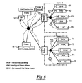
- FIG. 5 is an example, for the sake of discussion, of a possible residential deployment.
- FIG. 6 is an example with four different logical interactions shown.
- FIG. 7 is an exemplary appliance utilizing the node element and communication system of the invention.
- the operational support system (OSS) component 10 at the top depicts the pervasive nature of OSS (operational support system) and that it participates in the process at all levels.
- One goal of this invention is to provide architectures and architectural elements for interactions between network elements to facilitate an advanced power delivery system that can, among other things:
- This architecture advocates using one basic structure, namely the Node Element described later, and applying it throughout the advanced power network.
- the Node Element has optional features and different performance levels to meet a wide range o needs.
- Each Node Element instantiation has a specific set of features and performance levels that are tailored to that location.
- a common structure can be used, as proposed above, at each node at every layer throughout the network, as diagrammed in FIG. 2 , because a shared set of capabilities including peer-to-peer interactions, distributed computing, interface propagation and data aggregation fulfills the requirements for all applications.
- Node Elements are shown as black dots. As will be more fully described herein, these Node Elements make it possible to propagate interfaces, such as interface 20 across the network, to essentially any network layer, as needed.
- a peer-to-peer capability makes interactions potentially more efficient and more reliable.
- Distributed computing permits using more powerful computational methods and allows for autonomous operation.
- Data aggregation supplies a nodes distributed computations with the data needed to carry out their tasks.
- Propagating interfaces provides effective and direct remote, real-time control of devices between any two locations in the network.
- This architectural theme is to use a single highly flexible Node Element, configured to meet the needs of each specific application, to build an advanced power network from generation points to final consumption points.
- the proxy concept allows vastly different devices (e.g., PC's, HVAC units, etc.) connected with vastly different communications networks (e.g., wireless, HPNA, PLC, etc.) to interact with each other to exchange information and control commands.
- vastly different devices e.g., PC's, HVAC units, etc.
- vastly different communications networks e.g., wireless, HPNA, PLC, etc.
- elements deep in the global network to have precise and real-time control over devices by assessing their interfaces directly through the proxy.
- Self-healing is made possible because of the continuously updated Global Structured Aggregate information available at each node and the small autonomous subnets formed with peer-to-peer interactions. Given these features, it is possible to built a network that can anticipate or have knowledge of network faults and reconfigure to compensate.
- the interaction is further enhanced with several other features.
- the first is the ability of the node elements to make local interfaces, from devices in their sub-networks, available to devices at various locations within the global network.
- the next is to promote efficient distributed processing among node elements.
- peer-to-peer style communications is made available to all node elements.
- Node Element The concept of a node element is shown in FIG. 3 .
- the node element has two external ports; one for interactions with the global network (Global Port or GLP) and the other interacts with a subset network (Inward Port of INP).
- GLP Global Port
- INP Inward Port of INP
- the GLP (Global Port) gives access to the inward networks structured aggregate (Local Structured Aggregate or LSA) as well as certain local interfaces. Additionally, the GLP maintains the global structured aggregates (GSA) for use by the proxy and the inward network devices.
- GSA global Structured aggregates
- the inward port maintains the inward networks local device data, services and so on.
- Efficient peer-to-peer communications among node elements is part of the design of the GLP/INP. Global availability of local device interfaces along with peer-to-peer communications make real-time control possible. What's more, with less entities directly involved in the interactions, there is a higher level of reliability.
- Distributed computing among node elements gives the network more autonomy and is a built-in feature of each node element.
- Global aggregates are used in distributed computing for a portion of the data used in computations.
- Planes of Interaction There are three planes of interactions at each node; namely, Power Analysis and Monitor (PA/M) 41 , Data Plane (DP) 42 and Control Plane (CP) 43 and this concept is presented in FIG. 4 .
- PA/M Power Analysis and Monitor
- DP Data Plane
- CP Control Plane
- the PA/M (Power Analysis and Monitor) plane of interaction 41 can be used for implementing, for example, Power Quality of Service (pQoS).
- the DP (Data Plane) of interaction 42 is for data communications such as connections to the Internet.
- the CP (Control Plane) 43 is used to make real time adjustments, as an example, to power consumption devices such as HVAC units to meet local and/or global objections.
- Node Elements are employed throughout the power network. Node elements are modular blocks with a set of optional features that can be included or excluded based on the needs of the specific application. Optional features include:
- the node elements have options, again the choice depends on the application, and they include:
- FIG. 5 One of many possible arrangements for residential installations is shown in FIG. 5 .
- This configuration represents a realistic subset of devices in a home 51 and the configuration will be used to explain the overall concept. It is important to note that this example is but one of many and in no way restricts then generality of the invention.
- the communications form for power consumption devices in each house is in-home PLC (e.g., Home Plug Alliance or HPA).
- Data communications between the gateway and a PC 52 in one case is with wireless (802.11a) and the other is HPNA.
- PC 52 e.g., Internet access
- HPNA wireless 802.11a
- Access PLC is used, for this particular example, at the LV and MV distribution, although the concept is general and any form would work.
- Each device has its own capabilities and may have a unique commence interface.
- the HVAC system 53 would have controls for activating the ventilation fans (e.g., controlled to maintain air freshness), the heating element (e.g., controlled to keep the home warm in the cold weather) and the air conditioning pump (e.g., controlled to keep the home cool in the summer). It would also use, among other possible inputs, environmental conditions from indoor and outdoor sensors such as temperature and humidity to operate.
- the water heater 54 has only one control function; namely to maintain a constant water temperature, although it could use some of the same inputs as the HVAC system. Since there are many makes and models of these types of equipment, note that there will be different command structures and protocols for each.
- the logical picture in FIG. 6 shows the devices interaction opportunities and some specific examples.
- the node elements may be physically located within devices (e.g., residential gateway or RGW, DHW, etc.) r as a stand-alone piece of equipment.
- Example 1 One example of device interactions (Example 1) between the HVAC unit 72 and the IPM 74 (Intelligent Power Meter) in Home N.
- the two device proxies allow them to interact, pass data back and forth, exchange capabilities and so on. This interaction may be used to take advantage of market based power pricing by setting the in-home temperature to a bit higher level in the summer during times when the price of electricity is higher.
- interactions between the two devices are peer-to-peer and yet each device has access to information from other entities (e.g., the IPM 74 gets pricing information from entities in the global network, etc.).
- Distributed computing is utilitized to accomplish the task (e.g., the HVAC unit's temperature, humidity and air freshness control system; the ability of the IPM 74 to fetch pricing data and make predictions if the data is not available, etc.) and the task can be performed more or less autonomously, depending on prevailing conditions.
- the task e.g., the HVAC unit's temperature, humidity and air freshness control system; the ability of the IPM 74 to fetch pricing data and make predictions if the data is not available, etc.
- the task can be performed more or less autonomously, depending on prevailing conditions.
- Example 2 Another example of interactions between devices (Example 2) is shown in the figure between the hot water heater (DHW) 71 in Home N and the local power source 81 .
- the various proxies allow these two devices to interact and exchange information and control.
- the interaction may be a query by the hot water heater 71 to determine if there is sufficient power for a requested water demand for the dishwasher to start.
- the ability of the two devices to communicate peer-to-peer means that the decision-making process happens quickly and directly.
- Each of the two devices has access to other network devices (e.g., the DHW 71 is in contact with the dishwasher and the Local Power Source 81 is in constant contact with the generation and distribution grid).
- Each device has its own computing tasks (e.g., the DHW 71 runs a control algorithm for maintaining temperature and changing the setting to meet existing conditions, while the local power source 81 monitors its internal condition to determine available energy levels).
- Example 3 shows a PC in Home 1 interacting with an ISP to access the Internet.
- the residential gateway has an 802.11a proxy 66 to make the connection to the PC 65 and then to the ISP 82 at the other end.
- the proxy concept allows direct device interfaces to be made available at different levels in the hierarchy. So, for instance (Example 4), the interface to the HVAC system 62 in Home 1 may have its entire control interface available to a service element in the distribution network to enable a home service contract to be maintained. That is, the service element would query the HVAC system 62 on a regular basis to access operational data (e.g., fan total run time to determine filter replacement needs, etc.). It may need to control the unit to verify that it is operating within set limits (e.g., start the burner to view the color and size of the flame). Armed with this data, a service call could be scheduled toreplace parts or perform needed maintenance.
- operational data e.g., fan total run time to determine filter replacement needs, etc.
Abstract
Description
-
- Is self-healing,
- Is secure,
- Provides for market based pricing features,
- Supports a wide variety of different local and remote power generation systems,
- Has advanced data communications features for end customers,
- Interacts with consumer power-consumption devices, and
- Facilitates real time and other interactions between any elements
-
- Can communicate with one another peer-to-peer,
- Can form part of a distributed computing infrastructure,
- Can propagate their control interface to another entity, allowing heretofore unrealized remote control and system integration via proxy,
- Can communicate over the internet, and
- Can participate in sophisticated, real-time control schemes.
-
- Be self-healing
- Be secure
- Provide for market based pricing features
- Support a wide variety of different local and remote power generation systems
- Have advanced data communications features for end customers
- Interact with consumer power-consumption devices
- Facilitate real time and other interactions between any elements
-
- Power hierarchy
- Multiple generation points feed into the transmission grid (High Voltage or HV). In
FIG. 1 , seetransmission network 12. - Points on the transmission grid feed into distribution grids (Medium Voltage or MV). In
FIG. 1 , seedistribution network 14. - Points on the distribution grid fee into LV (Low Voltage) networks and then to individual consumption points (e.g., industrial locations, commercial establishments, individual homes, street lights and so on). In
FIG. 1 , see lowvoltage distribution network 16. - Inside the home, there are many power consumption points (e.g., Heating, Ventilation and Air Conditioning or HVAC, domestic hot water heaters or DHW, etc.). In
FIG. 1 , see the exemplary in-home LAN 18.
- Multiple generation points feed into the transmission grid (High Voltage or HV). In
- Interworking hierarchy
- Transmission grid interworking network would be based on high speed fiber
- Distribution grid interworking could be based on various different forms (e.g., Power Line Communications or PLC, Local Multipoint Distribution System or LMDS, Multi-channel Multipoint Distribution Service or MMDS, etc.)
- Communications at power consumption points inside the home could use various forms as well (e.g., PLC, Home Phone Line Alliance or HPNA, wireless such as 802.11a, IEEE1394, Ethernet, etc.)
- OSS oversees the entire network in a distributed fashion
- Node Elements
- Supports many physical and logical interfaces
- Facilitates interactions between dissimilar devices
- Permits efficient distributed processing among nodes
- Allows peer-to-peer style interactions among nodes
- Generates structured aggregates (e.g., data, services, etc.) on all devices on the inward port
- Maintains global structured aggregates on all global port devices (e.g., data, services, etc.)
- Makes selected local interfaces available to elements at any level in the hierarchy
- Power hierarchy
-
- Real-Time Interface Propagation (i.e., interface details)
- Aggregate Method (i.e., which variables, which services, etc.)
- Support for PA/M, DP and/or CP
-
- Communications security options (e.g., DES, 3DES, etc.)
- Communications QoS options (e.g., best effort, committed information rate, etc.)
- Performance options (e.g., hard real-time, real-time, on-line, etc.)
- Computational options (e.g., signal processing, data processing, etc.)
Claims (20)
Priority Applications (1)
| Application Number | Priority Date | Filing Date | Title |
|---|---|---|---|
| US10/621,112 US9236770B2 (en) | 2002-07-16 | 2003-07-16 | Atomic self-healing architecture in an electric power network |
Applications Claiming Priority (2)
| Application Number | Priority Date | Filing Date | Title |
|---|---|---|---|
| US39636902P | 2002-07-16 | 2002-07-16 | |
| US10/621,112 US9236770B2 (en) | 2002-07-16 | 2003-07-16 | Atomic self-healing architecture in an electric power network |
Publications (2)
| Publication Number | Publication Date |
|---|---|
| US20050043858A1 US20050043858A1 (en) | 2005-02-24 |
| US9236770B2 true US9236770B2 (en) | 2016-01-12 |
Family
ID=30116017
Family Applications (1)
| Application Number | Title | Priority Date | Filing Date |
|---|---|---|---|
| US10/621,112 Active 2031-01-04 US9236770B2 (en) | 2002-07-16 | 2003-07-16 | Atomic self-healing architecture in an electric power network |
Country Status (3)
| Country | Link |
|---|---|
| US (1) | US9236770B2 (en) |
| AU (1) | AU2003253934A1 (en) |
| WO (1) | WO2004008375A1 (en) |
Cited By (3)
| Publication number | Priority date | Publication date | Assignee | Title |
|---|---|---|---|---|
| US10548036B2 (en) | 2016-02-09 | 2020-01-28 | Spatialbuzz Limited | Fault monitoring by assessing spatial distribution of queries in a utility supply network |
| US10601073B2 (en) | 2016-03-08 | 2020-03-24 | Murata Manufacturing Co., Ltd. | Solid electrolyte, all solid state battery, method for producing solid electrolyte, and method for producing all solid state battery |
| US11082323B2 (en) | 2016-02-09 | 2021-08-03 | Spatialbuzz Limited | Fault monitoring in a utility supply network |
Families Citing this family (20)
| Publication number | Priority date | Publication date | Assignee | Title |
|---|---|---|---|---|
| EP1656745B1 (en) * | 2003-04-08 | 2016-04-06 | ACN Advanced Communications Networks SA | System and method for data communication over power lines |
| GB2446199A (en) | 2006-12-01 | 2008-08-06 | David Irvine | Secure, decentralised and anonymous peer-to-peer network |
| CA2665397A1 (en) | 2008-04-14 | 2009-10-14 | Robert F. Cruickshank, Iii | A method & apparatus for orchestrating utility power supply & demand in real time using a continuous pricing signal sent via a network to home networks & smart appliances |
| US8655995B2 (en) * | 2009-01-13 | 2014-02-18 | Whirlpool Corporation | Home network commissioning |
| US20110077878A1 (en) * | 2009-09-30 | 2011-03-31 | Lathrop Frederick L | Power supply with data communications |
| US8504214B2 (en) | 2010-06-18 | 2013-08-06 | General Electric Company | Self-healing power grid and method thereof |
| US9189042B2 (en) | 2010-09-27 | 2015-11-17 | Hewlett-Packard Development Company, L.P. | Computer system with power measurement |
| GB2486016A (en) * | 2010-12-02 | 2012-06-06 | Sony Corp | Control of storage devices in an electric power network |
| US9024471B2 (en) | 2011-05-02 | 2015-05-05 | Stmicroelectronics, Inc. | System and method for an intelligent power controller |
| US9283863B2 (en) | 2011-05-04 | 2016-03-15 | Siemens Aktiengesellschaft | Method and apparatus for providing electrical energy |
| US8995280B2 (en) | 2011-11-11 | 2015-03-31 | Stmicroelectronics, Inc. | System and method for an energy efficient network adapter |
| US9801114B2 (en) | 2011-11-11 | 2017-10-24 | Stmicroelectronics, Inc. | System and method for an energy efficient network adaptor with security provisions |
| US9130657B2 (en) * | 2012-10-19 | 2015-09-08 | Stmicroelectronics, Inc. | System and method for a power line modem |
| DE102012221571A1 (en) * | 2012-11-26 | 2014-05-28 | Siemens Aktiengesellschaft | Method for computer-aided control of an electrical power distribution network from a plurality of network nodes |
| CN103185372B (en) * | 2013-04-03 | 2015-06-10 | 谷振宇 | Internet of things heating and air conditioning energy-saving water-saving control system |
| CN103617493B (en) * | 2013-11-27 | 2016-07-27 | 北京国电通网络技术有限公司 | A kind of task processing method and device |
| CA2969381C (en) * | 2014-12-01 | 2023-12-05 | 3M Innovative Properties Company | Systems and methods for predicting hvac filter change |
| CN105896573B (en) * | 2016-06-03 | 2018-04-24 | 西南交通大学 | A kind of Poewr control method for energy internet composite energy storage system |
| CA3079938A1 (en) * | 2017-10-24 | 2019-05-02 | 3M Innovative Properties Company | Systems and methods for predicting hvac filter change using temperature measurements |
| CN110138089B (en) * | 2019-06-06 | 2021-12-28 | 国网北京市电力公司 | Batch preset communication method for distribution network automation master station |
Citations (13)
| Publication number | Priority date | Publication date | Assignee | Title |
|---|---|---|---|---|
| US5237511A (en) * | 1990-10-29 | 1993-08-17 | Westronic, Inc. | Distribution automation smart remote terminal unit |
| US5650936A (en) * | 1994-12-30 | 1997-07-22 | Cd Power Measurement Limited | Power monitor apparatus and method with object oriented structure |
| US20020111755A1 (en) * | 2000-10-19 | 2002-08-15 | Tti-Team Telecom International Ltd. | Topology-based reasoning apparatus for root-cause analysis of network faults |
| US6640890B1 (en) * | 1999-12-22 | 2003-11-04 | Visteon Global Technologies, Inc. | Multiple zone automatic HVAC control system and method |
| US6650876B1 (en) * | 1999-08-24 | 2003-11-18 | Telefonaktiebolaget Lm Ericsson (Publ) | Methods and arrangement relating to a radio communication network |
| US6751562B1 (en) * | 2000-11-28 | 2004-06-15 | Power Measurement Ltd. | Communications architecture for intelligent electronic devices |
| US20050144437A1 (en) * | 1994-12-30 | 2005-06-30 | Ransom Douglas S. | System and method for assigning an identity to an intelligent electronic device |
| US6944555B2 (en) * | 1994-12-30 | 2005-09-13 | Power Measurement Ltd. | Communications architecture for intelligent electronic devices |
| US6961641B1 (en) * | 1994-12-30 | 2005-11-01 | Power Measurement Ltd. | Intra-device communications architecture for managing electrical power distribution and consumption |
| US6988025B2 (en) * | 2000-11-28 | 2006-01-17 | Power Measurement Ltd. | System and method for implementing XML on an energy management device |
| US20060212194A1 (en) * | 1995-06-07 | 2006-09-21 | Automotive Technologies International, Inc. | Vehicle Communications Using the Internet |
| US7124397B1 (en) * | 2000-05-05 | 2006-10-17 | Ge Fanuc Automation North America, Inc. | Power builder for power management control system automation software |
| US20080107188A1 (en) * | 2001-03-20 | 2008-05-08 | Lightwaves Systems, Inc. | High bandwidth data transport system |
Family Cites Families (3)
| Publication number | Priority date | Publication date | Assignee | Title |
|---|---|---|---|---|
| US4804938A (en) * | 1986-10-24 | 1989-02-14 | Sangamo Weston, Inc. | Distribution energy management system |
| US5572438A (en) * | 1995-01-05 | 1996-11-05 | Teco Energy Management Services | Engery management and building automation system |
| US5668446A (en) * | 1995-01-17 | 1997-09-16 | Negawatt Technologies Inc. | Energy management control system for fluorescent lighting |
-
2003
- 2003-07-16 US US10/621,112 patent/US9236770B2/en active Active
- 2003-07-16 WO PCT/US2003/022152 patent/WO2004008375A1/en not_active Application Discontinuation
- 2003-07-16 AU AU2003253934A patent/AU2003253934A1/en not_active Abandoned
Patent Citations (13)
| Publication number | Priority date | Publication date | Assignee | Title |
|---|---|---|---|---|
| US5237511A (en) * | 1990-10-29 | 1993-08-17 | Westronic, Inc. | Distribution automation smart remote terminal unit |
| US6944555B2 (en) * | 1994-12-30 | 2005-09-13 | Power Measurement Ltd. | Communications architecture for intelligent electronic devices |
| US5650936A (en) * | 1994-12-30 | 1997-07-22 | Cd Power Measurement Limited | Power monitor apparatus and method with object oriented structure |
| US6961641B1 (en) * | 1994-12-30 | 2005-11-01 | Power Measurement Ltd. | Intra-device communications architecture for managing electrical power distribution and consumption |
| US20050144437A1 (en) * | 1994-12-30 | 2005-06-30 | Ransom Douglas S. | System and method for assigning an identity to an intelligent electronic device |
| US20060212194A1 (en) * | 1995-06-07 | 2006-09-21 | Automotive Technologies International, Inc. | Vehicle Communications Using the Internet |
| US6650876B1 (en) * | 1999-08-24 | 2003-11-18 | Telefonaktiebolaget Lm Ericsson (Publ) | Methods and arrangement relating to a radio communication network |
| US6640890B1 (en) * | 1999-12-22 | 2003-11-04 | Visteon Global Technologies, Inc. | Multiple zone automatic HVAC control system and method |
| US7124397B1 (en) * | 2000-05-05 | 2006-10-17 | Ge Fanuc Automation North America, Inc. | Power builder for power management control system automation software |
| US20020111755A1 (en) * | 2000-10-19 | 2002-08-15 | Tti-Team Telecom International Ltd. | Topology-based reasoning apparatus for root-cause analysis of network faults |
| US6751562B1 (en) * | 2000-11-28 | 2004-06-15 | Power Measurement Ltd. | Communications architecture for intelligent electronic devices |
| US6988025B2 (en) * | 2000-11-28 | 2006-01-17 | Power Measurement Ltd. | System and method for implementing XML on an energy management device |
| US20080107188A1 (en) * | 2001-03-20 | 2008-05-08 | Lightwaves Systems, Inc. | High bandwidth data transport system |
Non-Patent Citations (2)
| Title |
|---|
| "The IDC Engineers Pocket Guide", {51 pages} published 1994, 1995, 1996, 1997, 1998, 1999, 2000 and 2003 by IDC Technologies. * |
| Teco and IBM: The "Smart house" IS Here; Newsbytes, Inc.; 2 pages. * |
Cited By (3)
| Publication number | Priority date | Publication date | Assignee | Title |
|---|---|---|---|---|
| US10548036B2 (en) | 2016-02-09 | 2020-01-28 | Spatialbuzz Limited | Fault monitoring by assessing spatial distribution of queries in a utility supply network |
| US11082323B2 (en) | 2016-02-09 | 2021-08-03 | Spatialbuzz Limited | Fault monitoring in a utility supply network |
| US10601073B2 (en) | 2016-03-08 | 2020-03-24 | Murata Manufacturing Co., Ltd. | Solid electrolyte, all solid state battery, method for producing solid electrolyte, and method for producing all solid state battery |
Also Published As
| Publication number | Publication date |
|---|---|
| US20050043858A1 (en) | 2005-02-24 |
| WO2004008375A1 (en) | 2004-01-22 |
| AU2003253934A1 (en) | 2004-02-02 |
Similar Documents
| Publication | Publication Date | Title |
|---|---|---|
| US9236770B2 (en) | Atomic self-healing architecture in an electric power network | |
| US11391600B2 (en) | Interfacing to resource consumption management devices | |
| Son et al. | Home energy management system based on power line communication | |
| Katipamula et al. | VOLTTRON: An open-source software platform of the future | |
| US9515491B2 (en) | Managing devices within micro-grids | |
| Jain et al. | Survey on smart grid technologies-smart metering, IoT and EMS | |
| US20110063126A1 (en) | Communications hub for resource consumption management | |
| Tan et al. | M2M communications in the smart grid: Applications, standards, enabling technologies, and research challenges | |
| CN102232177B (en) | Method and distributed system for detecting and managing data from plurality of measuring devices | |
| Alhasnawi et al. | A new Internet of Things based optimization scheme of residential demand side management system | |
| Ghosh et al. | Design of smart grid in an University Campus using ZigBee mesh networks | |
| Lai et al. | Smart demand response based on smart homes | |
| CA2749659C (en) | Communications hub for resource consumption management | |
| US8847783B2 (en) | High speed utility backhaul communication system | |
| JP6591968B2 (en) | In-house management of home area network | |
| CN103036944A (en) | Communication with distributed devices handling electric energy via the internet | |
| US10916968B2 (en) | Third party energy management | |
| Barker et al. | Smart Homes or Real Homes: Building a Smarter Grid With “Dumb” Houses | |
| JP2015141482A (en) | power management method, and system | |
| Di Zenobio et al. | An IoT platform integrated into an energy efficient DC lighting grid | |
| KR101365168B1 (en) | Small independence area power control system using cloud service and method thereof | |
| CA2749628C (en) | Interfacing to resource consumption management devices | |
| US20230376444A1 (en) | Building management system with universal serial bus (usb) building devices | |
| Pournaras et al. | Peer-to-peer aggregation for dynamic adjustments in power demand | |
| Valentin et al. | Software system for monitoring data traffic from a Smart Grid network |
Legal Events
| Date | Code | Title | Description |
|---|---|---|---|
| AS | Assignment |
Owner name: ENIKIA, LLC, NEW JERSEY Free format text: ASSIGNMENT OF ASSIGNORS INTEREST;ASSIGNORS:GELMAN, ALEXANDER;LOGVINOV, OLEG;DURFEE, LAWRENCE;AND OTHERS;SIGNING DATES FROM 20031023 TO 20031210;REEL/FRAME:014799/0832 Owner name: MATSUSHITA ELECTRIC COMPANY OF AMERICA, NEW JERSEY Free format text: ASSIGNMENT OF ASSIGNORS INTEREST;ASSIGNORS:GELMAN, ALEXANDER;LOGVINOV, OLEG;DURFEE, LAWRENCE;AND OTHERS;SIGNING DATES FROM 20031023 TO 20031210;REEL/FRAME:014799/0832 Owner name: MATSUSHITA ELECTRIC COMPANY OF AMERICA, NEW JERSEY Free format text: ASSIGNMENT OF ASSIGNORS INTEREST;ASSIGNORS:GELMAN, ALEXANDER;LOGVINOV, OLEG;DURFEE, LAWRENCE;AND OTHERS;REEL/FRAME:014799/0832;SIGNING DATES FROM 20031023 TO 20031210 Owner name: ENIKIA, LLC, NEW JERSEY Free format text: ASSIGNMENT OF ASSIGNORS INTEREST;ASSIGNORS:GELMAN, ALEXANDER;LOGVINOV, OLEG;DURFEE, LAWRENCE;AND OTHERS;REEL/FRAME:014799/0832;SIGNING DATES FROM 20031023 TO 20031210 |
|
| AS | Assignment |
Owner name: MILETOS, INC., NEW JERSEY Free format text: BILL OF SALE;ASSIGNOR:ENIKIA, LLC;REEL/FRAME:014608/0163 Effective date: 20040323 |
|
| AS | Assignment |
Owner name: ARKADOS, INC., NEW JERSEY Free format text: MERGER;ASSIGNOR:MILETOS, INC.;REEL/FRAME:015042/0804 Effective date: 20040521 |
|
| AS | Assignment |
Owner name: PANASONIC CORPORATION OF NORTH AMERICA, NEW JERSEY Free format text: MERGER;ASSIGNOR:MATSUSHITA ELECTRIC CORPORATION OF AMERICA;REEL/FRAME:015972/0511 Effective date: 20041123 |
|
| AS | Assignment |
Owner name: BUSHIDO CAPITAL MASTER FUND, LP, NEW YORK Free format text: SECURITY AGREEMENT;ASSIGNOR:ARKADOS, INC.;REEL/FRAME:022416/0682 Effective date: 20051228 Owner name: GAMMA OPPOURTUNITY CAPITAL PARTNERS, LP CLASS A, N Free format text: SECURITY AGREEMENT;ASSIGNOR:ARKADOS, INC.;REEL/FRAME:022416/0682 Effective date: 20051228 Owner name: GAMMA OPPORTUNITY CAPITAL PARTNERS, LP CLASS C, NE Free format text: SECURITY AGREEMENT;ASSIGNOR:ARKADOS, INC.;REEL/FRAME:022416/0682 Effective date: 20051228 Owner name: CRUCIAN TRANSITION, INC., NEW YORK Free format text: SECURITY AGREEMENT;ASSIGNOR:ARKADOS, INC.;REEL/FRAME:022416/0682 Effective date: 20051228 Owner name: CARGO HOLDINGS LLC, NEW YORK Free format text: SECURITY AGREEMENT;ASSIGNOR:ARKADOS, INC.;REEL/FRAME:022416/0682 Effective date: 20051228 Owner name: TYPALDOS, ANDREAS, NEW YORK Free format text: SECURITY AGREEMENT;ASSIGNOR:ARKADOS, INC.;REEL/FRAME:022416/0682 Effective date: 20051228 Owner name: ANDREAS TYPALDOS FAMILY LIMITED PARTNERSHIP, NEW Y Free format text: SECURITY AGREEMENT;ASSIGNOR:ARKADOS, INC.;REEL/FRAME:022416/0682 Effective date: 20051228 Owner name: TYPALDOS, KATHRYN, NEW YORK Free format text: SECURITY AGREEMENT;ASSIGNOR:ARKADOS, INC.;REEL/FRAME:022416/0682 Effective date: 20051228 Owner name: SOMMER, HERBERT, NEW YORK Free format text: SECURITY AGREEMENT;ASSIGNOR:ARKADOS, INC.;REEL/FRAME:022416/0682 Effective date: 20051228 Owner name: SCHNEIDER, JOEL C, NEW YORK Free format text: SECURITY AGREEMENT;ASSIGNOR:ARKADOS, INC.;REEL/FRAME:022416/0682 Effective date: 20051228 Owner name: VENDOME, GENNARO, NEW YORK Free format text: SECURITY AGREEMENT;ASSIGNOR:ARKADOS, INC.;REEL/FRAME:022416/0682 Effective date: 20051228 Owner name: CARSON, WILLIAM H, TEXAS Free format text: SECURITY AGREEMENT;ASSIGNOR:ARKADOS, INC.;REEL/FRAME:022416/0682 Effective date: 20051228 Owner name: BCMF TRUSTEES, LLC, NEW YORK Free format text: SECURITY AGREEMENT;ASSIGNOR:ARKADOS, INC.;REEL/FRAME:022416/0682 Effective date: 20051228 Owner name: ACMSPV LLC, NEW YORK Free format text: SECURITY AGREEMENT;ASSIGNOR:ARKADOS, INC.;REEL/FRAME:022416/0682 Effective date: 20051228 Owner name: CFRR HOLDINGS LLC, NEW YORK Free format text: SECURITY AGREEMENT;ASSIGNOR:ARKADOS, INC.;REEL/FRAME:022416/0682 Effective date: 20051228 Owner name: RABMAN, RALPH, SOUTH AFRICA Free format text: SECURITY AGREEMENT;ASSIGNOR:ARKADOS, INC.;REEL/FRAME:022416/0682 Effective date: 20051228 Owner name: PIERCE DIVERSIFIED STRATEGY MASTER FUND LLC SERIES Free format text: SECURITY AGREEMENT;ASSIGNOR:ARKADOS, INC.;REEL/FRAME:022416/0682 Effective date: 20051228 Owner name: BUSHIDO CAPITAL MASTER FUND, LP,NEW YORK Free format text: SECURITY AGREEMENT;ASSIGNOR:ARKADOS, INC.;REEL/FRAME:022416/0682 Effective date: 20051228 Owner name: GAMMA OPPOURTUNITY CAPITAL PARTNERS, LP CLASS A,NE Free format text: SECURITY AGREEMENT;ASSIGNOR:ARKADOS, INC.;REEL/FRAME:022416/0682 Effective date: 20051228 Owner name: GAMMA OPPORTUNITY CAPITAL PARTNERS, LP CLASS C,NEW Free format text: SECURITY AGREEMENT;ASSIGNOR:ARKADOS, INC.;REEL/FRAME:022416/0682 Effective date: 20051228 Owner name: CRUCIAN TRANSITION, INC.,NEW YORK Free format text: SECURITY AGREEMENT;ASSIGNOR:ARKADOS, INC.;REEL/FRAME:022416/0682 Effective date: 20051228 Owner name: CARGO HOLDINGS LLC,NEW YORK Free format text: SECURITY AGREEMENT;ASSIGNOR:ARKADOS, INC.;REEL/FRAME:022416/0682 Effective date: 20051228 Owner name: TYPALDOS, ANDREAS,NEW YORK Free format text: SECURITY AGREEMENT;ASSIGNOR:ARKADOS, INC.;REEL/FRAME:022416/0682 Effective date: 20051228 Owner name: ANDREAS TYPALDOS FAMILY LIMITED PARTNERSHIP,NEW YO Free format text: SECURITY AGREEMENT;ASSIGNOR:ARKADOS, INC.;REEL/FRAME:022416/0682 Effective date: 20051228 Owner name: TYPALDOS, KATHRYN,NEW YORK Free format text: SECURITY AGREEMENT;ASSIGNOR:ARKADOS, INC.;REEL/FRAME:022416/0682 Effective date: 20051228 Owner name: SOMMER, HERBERT,NEW YORK Free format text: SECURITY AGREEMENT;ASSIGNOR:ARKADOS, INC.;REEL/FRAME:022416/0682 Effective date: 20051228 Owner name: SCHNEIDER, JOEL C,NEW YORK Free format text: SECURITY AGREEMENT;ASSIGNOR:ARKADOS, INC.;REEL/FRAME:022416/0682 Effective date: 20051228 Owner name: VENDOME, GENNARO,NEW YORK Free format text: SECURITY AGREEMENT;ASSIGNOR:ARKADOS, INC.;REEL/FRAME:022416/0682 Effective date: 20051228 Owner name: CARSON, WILLIAM H,TEXAS Free format text: SECURITY AGREEMENT;ASSIGNOR:ARKADOS, INC.;REEL/FRAME:022416/0682 Effective date: 20051228 Owner name: BCMF TRUSTEES, LLC,NEW YORK Free format text: SECURITY AGREEMENT;ASSIGNOR:ARKADOS, INC.;REEL/FRAME:022416/0682 Effective date: 20051228 Owner name: ACMSPV LLC,NEW YORK Free format text: SECURITY AGREEMENT;ASSIGNOR:ARKADOS, INC.;REEL/FRAME:022416/0682 Effective date: 20051228 Owner name: CFRR HOLDINGS LLC,NEW YORK Free format text: SECURITY AGREEMENT;ASSIGNOR:ARKADOS, INC.;REEL/FRAME:022416/0682 Effective date: 20051228 Owner name: RABMAN, RALPH,SOUTH AFRICA Free format text: SECURITY AGREEMENT;ASSIGNOR:ARKADOS, INC.;REEL/FRAME:022416/0682 Effective date: 20051228 |
|
| AS | Assignment |
Owner name: THE ARKADOS GROUP (FORMERLY KNOWN AS CDKNET.COM, I Free format text: RELEASE BY SECURED PARTY;ASSIGNORS:ANDREAS TYPALDOS FAMILY LIMITED PARTNERSHIP;CARGO HOLDINGS LLC;TYPALDOS, ANDREAS;AND OTHERS;REEL/FRAME:026554/0322 Effective date: 20110624 Owner name: THE ARKADOS GROUP (FORMERLY KNOWN AS CDKNET.COM, I Free format text: RELEASE BY SECURED PARTY;ASSIGNORS:BUSHIDO CAPITAL MASTER FUND, LP;PIERCE DIVERSIFIED STRATEGY MASTER FUND LLC SERIES BUS;CRUCIAN TRANSITION, INC.;AND OTHERS;REEL/FRAME:026554/0550 Effective date: 20110624 Owner name: ARKADOS, INC., NEW JERSEY Free format text: RELEASE BY SECURED PARTY;ASSIGNORS:ANDREAS TYPALDOS FAMILY LIMITED PARTNERSHIP;CARGO HOLDINGS LLC;TYPALDOS, ANDREAS;AND OTHERS;REEL/FRAME:026554/0322 Effective date: 20110624 Owner name: ARKADOS, INC., NEW JERSEY Free format text: RELEASE BY SECURED PARTY;ASSIGNORS:BUSHIDO CAPITAL MASTER FUND, LP;PIERCE DIVERSIFIED STRATEGY MASTER FUND LLC SERIES BUS;CRUCIAN TRANSITION, INC.;AND OTHERS;REEL/FRAME:026554/0550 Effective date: 20110624 |
|
| AS | Assignment |
Owner name: STMICROELECTRONICS, INC., TEXAS Free format text: ASSIGNMENT OF ASSIGNORS INTEREST;ASSIGNOR:ARKADOS, INC.;REEL/FRAME:026800/0198 Effective date: 20110624 |
|
| AS | Assignment |
Owner name: STMICROELECTRONICS, INC., TEXAS Free format text: ASSIGNMENT OF ASSIGNORS INTEREST;ASSIGNOR:PANASONIC CORPORATION OF NORTH AMERICA FKA MATSUSHITA ELECTRIC CORPORATION OF AMERICA;REEL/FRAME:032355/0741 Effective date: 20140219 |
|
| STCF | Information on status: patent grant |
Free format text: PATENTED CASE |
|
| MAFP | Maintenance fee payment |
Free format text: PAYMENT OF MAINTENANCE FEE, 4TH YEAR, LARGE ENTITY (ORIGINAL EVENT CODE: M1551); ENTITY STATUS OF PATENT OWNER: LARGE ENTITY Year of fee payment: 4 |
|
| MAFP | Maintenance fee payment |
Free format text: PAYMENT OF MAINTENANCE FEE, 8TH YEAR, LARGE ENTITY (ORIGINAL EVENT CODE: M1552); ENTITY STATUS OF PATENT OWNER: LARGE ENTITY Year of fee payment: 8 |