US9238867B2 - Apparatus and method for high-throughput atomic layer deposition - Google Patents
Apparatus and method for high-throughput atomic layer deposition Download PDFInfo
- Publication number
- US9238867B2 US9238867B2 US12/993,361 US99336109A US9238867B2 US 9238867 B2 US9238867 B2 US 9238867B2 US 99336109 A US99336109 A US 99336109A US 9238867 B2 US9238867 B2 US 9238867B2
- Authority
- US
- United States
- Prior art keywords
- gas
- tunnel
- wall
- substrate
- process tunnel
- Prior art date
- Legal status (The legal status is an assumption and is not a legal conclusion. Google has not performed a legal analysis and makes no representation as to the accuracy of the status listed.)
- Active, expires
Links
Images


Classifications
-
- C—CHEMISTRY; METALLURGY
- C23—COATING METALLIC MATERIAL; COATING MATERIAL WITH METALLIC MATERIAL; CHEMICAL SURFACE TREATMENT; DIFFUSION TREATMENT OF METALLIC MATERIAL; COATING BY VACUUM EVAPORATION, BY SPUTTERING, BY ION IMPLANTATION OR BY CHEMICAL VAPOUR DEPOSITION, IN GENERAL; INHIBITING CORROSION OF METALLIC MATERIAL OR INCRUSTATION IN GENERAL
- C23C—COATING METALLIC MATERIAL; COATING MATERIAL WITH METALLIC MATERIAL; SURFACE TREATMENT OF METALLIC MATERIAL BY DIFFUSION INTO THE SURFACE, BY CHEMICAL CONVERSION OR SUBSTITUTION; COATING BY VACUUM EVAPORATION, BY SPUTTERING, BY ION IMPLANTATION OR BY CHEMICAL VAPOUR DEPOSITION, IN GENERAL
- C23C16/00—Chemical coating by decomposition of gaseous compounds, without leaving reaction products of surface material in the coating, i.e. chemical vapour deposition [CVD] processes
- C23C16/44—Chemical coating by decomposition of gaseous compounds, without leaving reaction products of surface material in the coating, i.e. chemical vapour deposition [CVD] processes characterised by the method of coating
- C23C16/54—Apparatus specially adapted for continuous coating
-
- C—CHEMISTRY; METALLURGY
- C23—COATING METALLIC MATERIAL; COATING MATERIAL WITH METALLIC MATERIAL; CHEMICAL SURFACE TREATMENT; DIFFUSION TREATMENT OF METALLIC MATERIAL; COATING BY VACUUM EVAPORATION, BY SPUTTERING, BY ION IMPLANTATION OR BY CHEMICAL VAPOUR DEPOSITION, IN GENERAL; INHIBITING CORROSION OF METALLIC MATERIAL OR INCRUSTATION IN GENERAL
- C23C—COATING METALLIC MATERIAL; COATING MATERIAL WITH METALLIC MATERIAL; SURFACE TREATMENT OF METALLIC MATERIAL BY DIFFUSION INTO THE SURFACE, BY CHEMICAL CONVERSION OR SUBSTITUTION; COATING BY VACUUM EVAPORATION, BY SPUTTERING, BY ION IMPLANTATION OR BY CHEMICAL VAPOUR DEPOSITION, IN GENERAL
- C23C16/00—Chemical coating by decomposition of gaseous compounds, without leaving reaction products of surface material in the coating, i.e. chemical vapour deposition [CVD] processes
- C23C16/44—Chemical coating by decomposition of gaseous compounds, without leaving reaction products of surface material in the coating, i.e. chemical vapour deposition [CVD] processes characterised by the method of coating
- C23C16/455—Chemical coating by decomposition of gaseous compounds, without leaving reaction products of surface material in the coating, i.e. chemical vapour deposition [CVD] processes characterised by the method of coating characterised by the method used for introducing gases into reaction chamber or for modifying gas flows in reaction chamber
- C23C16/45523—Pulsed gas flow or change of composition over time
- C23C16/45525—Atomic layer deposition [ALD]
- C23C16/45544—Atomic layer deposition [ALD] characterized by the apparatus
- C23C16/45548—Atomic layer deposition [ALD] characterized by the apparatus having arrangements for gas injection at different locations of the reactor for each ALD half-reaction
- C23C16/45551—Atomic layer deposition [ALD] characterized by the apparatus having arrangements for gas injection at different locations of the reactor for each ALD half-reaction for relative movement of the substrate and the gas injectors or half-reaction reactor compartments
-
- C—CHEMISTRY; METALLURGY
- C30—CRYSTAL GROWTH
- C30B—SINGLE-CRYSTAL GROWTH; UNIDIRECTIONAL SOLIDIFICATION OF EUTECTIC MATERIAL OR UNIDIRECTIONAL DEMIXING OF EUTECTOID MATERIAL; REFINING BY ZONE-MELTING OF MATERIAL; PRODUCTION OF A HOMOGENEOUS POLYCRYSTALLINE MATERIAL WITH DEFINED STRUCTURE; SINGLE CRYSTALS OR HOMOGENEOUS POLYCRYSTALLINE MATERIAL WITH DEFINED STRUCTURE; AFTER-TREATMENT OF SINGLE CRYSTALS OR A HOMOGENEOUS POLYCRYSTALLINE MATERIAL WITH DEFINED STRUCTURE; APPARATUS THEREFOR
- C30B25/00—Single-crystal growth by chemical reaction of reactive gases, e.g. chemical vapour-deposition growth
- C30B25/02—Epitaxial-layer growth
- C30B25/14—Feed and outlet means for the gases; Modifying the flow of the reactive gases
-
- C—CHEMISTRY; METALLURGY
- C30—CRYSTAL GROWTH
- C30B—SINGLE-CRYSTAL GROWTH; UNIDIRECTIONAL SOLIDIFICATION OF EUTECTIC MATERIAL OR UNIDIRECTIONAL DEMIXING OF EUTECTOID MATERIAL; REFINING BY ZONE-MELTING OF MATERIAL; PRODUCTION OF A HOMOGENEOUS POLYCRYSTALLINE MATERIAL WITH DEFINED STRUCTURE; SINGLE CRYSTALS OR HOMOGENEOUS POLYCRYSTALLINE MATERIAL WITH DEFINED STRUCTURE; AFTER-TREATMENT OF SINGLE CRYSTALS OR A HOMOGENEOUS POLYCRYSTALLINE MATERIAL WITH DEFINED STRUCTURE; APPARATUS THEREFOR
- C30B29/00—Single crystals or homogeneous polycrystalline material with defined structure characterised by the material or by their shape
- C30B29/10—Inorganic compounds or compositions
- C30B29/16—Oxides
- C30B29/20—Aluminium oxides
-
- C—CHEMISTRY; METALLURGY
- C30—CRYSTAL GROWTH
- C30B—SINGLE-CRYSTAL GROWTH; UNIDIRECTIONAL SOLIDIFICATION OF EUTECTIC MATERIAL OR UNIDIRECTIONAL DEMIXING OF EUTECTOID MATERIAL; REFINING BY ZONE-MELTING OF MATERIAL; PRODUCTION OF A HOMOGENEOUS POLYCRYSTALLINE MATERIAL WITH DEFINED STRUCTURE; SINGLE CRYSTALS OR HOMOGENEOUS POLYCRYSTALLINE MATERIAL WITH DEFINED STRUCTURE; AFTER-TREATMENT OF SINGLE CRYSTALS OR A HOMOGENEOUS POLYCRYSTALLINE MATERIAL WITH DEFINED STRUCTURE; APPARATUS THEREFOR
- C30B35/00—Apparatus not otherwise provided for, specially adapted for the growth, production or after-treatment of single crystals or of a homogeneous polycrystalline material with defined structure
- C30B35/005—Transport systems
-
- H—ELECTRICITY
- H01—ELECTRIC ELEMENTS
- H01L—SEMICONDUCTOR DEVICES NOT COVERED BY CLASS H10
- H01L21/00—Processes or apparatus adapted for the manufacture or treatment of semiconductor or solid state devices or of parts thereof
- H01L21/67—Apparatus specially adapted for handling semiconductor or electric solid state devices during manufacture or treatment thereof; Apparatus specially adapted for handling wafers during manufacture or treatment of semiconductor or electric solid state devices or components ; Apparatus not specifically provided for elsewhere
- H01L21/677—Apparatus specially adapted for handling semiconductor or electric solid state devices during manufacture or treatment thereof; Apparatus specially adapted for handling wafers during manufacture or treatment of semiconductor or electric solid state devices or components ; Apparatus not specifically provided for elsewhere for conveying, e.g. between different workstations
- H01L21/67784—Apparatus specially adapted for handling semiconductor or electric solid state devices during manufacture or treatment thereof; Apparatus specially adapted for handling wafers during manufacture or treatment of semiconductor or electric solid state devices or components ; Apparatus not specifically provided for elsewhere for conveying, e.g. between different workstations using air tracks
Definitions
- the invention relates to the field of thin film deposition, and, more particularly, to an apparatus and method for atomic layer deposition of films.
- Atomic layer deposition is a thin film deposition method that allows for the deposition of films having thicknesses on the order of nanometers in a precisely controlled way.
- ALD uses two or more gaseous precursors that are alternately and repeatedly applied to a substrate.
- a series of sequential steps in which a surface of the substrate is exposed to all precursors is called a deposition cycle.
- Each deposition cycle grows a single monolayer of film, or a fraction of a monolayer. This is due to the fact that, in ALD, film growth depends on chemisorption, a process whereby a precursor molecule adheres to a substrate's surface through the formation of a chemical bond (without further thermal decomposition of the precursor molecule taking place).
- ALD is a self-limiting layer-by-layer deposition method that offers highly conformal coating and excellent thickness control.
- ALD may be used to deposit aluminum oxide (Al 2 O 3 ) films for the passivation of advanced mono-Si solar cells.
- Al 2 O 3 aluminum oxide
- typical film thicknesses of 5-15 nm are required, which can be achieved using traditional single or multi-wafer ALD systems.
- the throughput of the most efficient multi-wafer ALD systems at said film thickness is about 60 wafers per hour.
- the amount of surface area to be treated in order to obtain—for example—a solar cell panel for use on a rooftop is considerable however.
- ALD apparatus featuring a higher throughput.
- the solar cell industry is exemplary only, and merely one of many industries in which the continual pressure for ALD equipment having an increased throughput is felt.
- Such higher throughput is preferably achieved using apparatus that are relatively simple from a constructional point of view. This is because, typically, the simpler an apparatus is, the more economically it may be built, the more reliable it is and the less servicing it requires. It is therefore an object of the present invention to provide a device and a method for atomic layer deposition offering an improved throughput capacity at a minimum level of constructional complexity.
- an atomic layer deposition apparatus includes a process tunnel that extends in a transport direction and that is bounded by at least a first, lower wall and a second, upper wall. Said walls are mutually parallel and spaced apart so as to allow a substantially flat substrate, oriented parallel to the walls, to be accommodated there between.
- the apparatus further includes a plurality of gas injection channels. These gas injection channels are provided in both the first wall and the second wall of the process tunnel and are disposed in a spaced apart manner along the transport direction.
- the gas injection channels in the first, lower wall are configured to provide a first, lower gas bearing, while the gas injection channels in the second, upper wall are configured to provide a second, upper gas bearing.
- the gas bearings are configured to floatingly support and accommodate substrates.
- gas injection channels in at least one of the first wall and the second wall are connected successively to a first precursor gas source, a purge gas source, a second precursor gas source and a purge gas source, so as to create a tunnel segment that—in use—comprises successive zones including a first precursor gas, a purge gas, a second precursor gas and a purge gas, respectively.
- Two or more of such tunnel segments are disposed in succession in the transport direction.
- at least a portion of the process tunnel has a downward slope ( ⁇ ), so as to enable gravity driven transport of substrates through said at least one process tunnel portion.
- a method for growing a film on a substrate.
- the method comprises providing a first, lower gas bearing and a second, upper gas bearing, said gas bearings being configured to floatingly support and accommodate the substrate between them.
- the gas bearings extend downwards in a longitudinal transport direction.
- the method also comprises providing a substrate, and supporting and accommodating it between the gas bearings.
- the method further comprises enabling gravity to convey the substrate along the gas bearings in the transport direction, while subjecting a surface of the substrate to an atomic layer deposition treatment.
- At least one of the first and second gas bearings is divided into two or more functional segments, each segment comprising at least four laterally extending zones that successively include a first precursor gas, a purge gas, a second precursor gas and a purge gas, respectively, and an atomic layer is deposited onto at least one surface of the substrate as it is conveyed through all at least four zones of a single functional segment of said gas bearing.
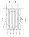
- FIG. 1 is a diagrammatic lateral cross-sectional view of an exemplary disclosed atomic layer deposition apparatus having two parallel tunnel walls between which a substrate is accommodated;
- FIG. 2 is a diagrammatic cross-sectional plan view of a portion of the process tunnel shown in FIG. 1 as viewed along line A-A, illustrating the arrangement of segments and zones;
- FIG. 3 is a diagrammatic longitudinal cross-sectional view of a portion of a process tunnel that is consistent with the embodiment shown in FIGS. 1 and 2 , wherein the upper and lower tunnel walls are configured asymmetrically;
- FIG. 4 is a diagrammatic longitudinal cross-sectional view of a portion of a process tunnel that is consistent with the embodiment shown in FIGS. 1 and 2 , wherein the upper and lower tunnel walls are configured symmetrically;
- FIG. 5 is diagrammatic longitudinal cross-sectional view of a portion of a process tunnel, used to clarify a mathematical model put forward in the specification;
- FIG. 6 is a diagrammatic longitudinal cross-sectional view of a portion of a process tunnel, wherein a number of gas injection channels inject gas into the tunnel space in a direction partly parallel to the transport direction, so as to aid in driving any substrates;
- FIG. 7 is a diagrammatic longitudinal cross-sectional view of a portion of a process tunnel, provided with an entrance section with an enlarged gap between the tunnel walls;
- FIG. 8 is a diagrammatic lateral cross-sectional view of an entrance section of a process tunnel.
- FIG. 9 is a diagrammatic top view of an exemplary embodiment of a mechanical substrate handler.
- the disclosed atomic layer deposition apparatus includes a process tunnel through which a substrate, preferably as part of a train of substrates, may be conveyed in a linear manner. That is, the substrate may be inserted into the tunnel at an entrance thereof to be conveyed to an exit.
- the tunnel is bounded by at least two substantially parallel tunnel walls. These tunnel walls are located close to both the substrate and each other, so as to provide an elongate processing space with a relatively small volume per unit of length.
- the process tunnel is divided into a series of segments. In use each segment comprises a number—typically four—of laterally extending gas zones. Successive zones within a segment comprise a first precursor gas, a purge gas, a second precursor gas, and a purge gas respectively.
- the substrate moves through the tunnel, its surface (e.g. its lower surface, its upper surface, or both) is strip-wise subjected to contact with the different gases.
- traversal of one tunnel segment may be equivalent to subjecting the substrate to one atomic layer deposition cycle.
- the tunnel may comprise as many segments as desired, a film of arbitrary thickness may be grown on a substrate during its crossing through the tunnel.
- the linear nature of the process tunnel enables a continuous stream of substrates to be processed, thus delivering an atomic layer deposition apparatus with an appreciably improved throughput capacity.
- the process tunnel is fitted with two gas bearings, located opposite each other and capable of receiving a substrate between them.
- a lower bearing supports the substrate from below, while an upper bearing covers substrate from above, thereby pressing it against the lower gas bearing so as to flatten it, and stabilize its position.
- the lower gas bearing may be provided for via the gas injection channels that are disposed in the lower, first tunnel wall, while the upper gas bearing may be provided for via the gas injection channels that are disposed in the upper, second tunnel wall.
- the process tunnel slopes downwards, so do the tunnel walls and the gas bearings provided therein. Consequently, a substrate accommodated by the gas bearings will experience a gravitational force (component) that pulls it in the transport direction.
- the presently disclosed apparatus thus features a substrate drive mechanism that is essentially passive in that substrates are gravity driven.
- Such a ‘gravity drive’ eliminates the need for a separate substrate conveyor whose parts are subject to soiling (due to their continuous traversal of the deposition environment maintained in the process tunnel), wear and inevitable periodic servicing, and as a result enables a simpler, more economical and more reliable ALD apparatus design.
- FIG. 1 is a diagrammatic lateral cross-sectional illustration of an exemplary disclosed atomic layer deposition apparatus 100 , suitable for depositing a film on a substrate 130 .
- the apparatus 100 comprises a process tunnel space 102 , which is bounded by a first, lower tunnel wall 110 , a second, upper tunnel wall 120 , and side walls 106 that connect the first and second tunnel walls.
- the tunnel walls 110 , 120 are substantially parallel and spaced apart from each other to allow the substrate 130 , e.g. a semiconductor wafer, to be accommodated there between.
- the tunnel walls 110 , 120 extend longitudinally in a transport direction 104 that is perpendicular to the plane of the drawing.
- the transport direction 104 and the tunnel walls 110 , 120 slope downwards (cf. FIGS. 3 and 4 ), at least locally.
- the tunnel walls 110 , 120 may be oriented horizontally, as shown, or have an inclination relative to the horizontal.
- Both tunnel walls 110 , 120 are fitted with a plurality of gas injection channels 112 and 122 , respectively.
- the outflow openings of the gas injection channels 112 , 122 are distributed over the inside surfaces of the respective tunnel walls 110 , 120 that are facing the substrate, both along the lateral and the longitudinal directions thereof.
- a lateral tunnel wall cross-section comprises nine gas injection channels 112 , 122 . It is contemplated, however, that a lateral tunnel wall cross-section may include a greater or lesser number of gas injection channels 112 , 122 .
- the gas injection channels 112 , 122 in the tunnel walls 110 , 120 are connected to (a number of) gas sources 114 and 124 , respectively.
- Gas injection channels in the same tunnel wall and at the same longitudinal position thereof may generally be connected to gas sources of the same gas or gas mixture.
- opposing gas channels that share the same longitudinal position of the process tunnel but are situated in opposite tunnel walls are connected to gas sources of the same gas composition depends on the desired configuration of the apparatus 100 . This aspect will be elaborated upon below with reference to FIGS. 3 and 4 . For now and the remainder of this specification, it will be tacitly assumed that opposing gas injection channels 112 , 122 at the same longitudinal position are configured to inject the same gas or gas mixture, unless stated otherwise.
- the gas injection channels 112 , 122 may inject gases into the tunnel space 102 over the whole length of the tunnel. Once injected, the gases flow laterally between the tunnel walls 110 , 120 . When a substrate 130 is present, this means that the gases flow laterally across the lower and upper surfaces 130 a, 130 b of the substrate 130 , towards the edges of the substrate and beyond. Lateral gas flows occur provided that the gases can escape at both lateral sides of the tunnel.
- the side walls 106 of the process tunnel may be provided with exhaust channels 108 .
- An exhaust channel 108 is preferably held at or around atmospheric pressure, so as to render vacuum pumps superfluous.
- an exhaust channel 108 may be held at a pressure that deviates from atmospheric pressure, such as a lower or higher pressure.
- the sidewalls 106 restrict the outflow of gas. They stagnate the lateral gas flows and cause pressure buildup in the tunnel space regions 103 adjacent the side walls 106 , which helps to stabilize the lateral position of the floating substrate 130 .
- the gas injection channels 112 in the lower, first wall 110 generally provide for the lateral gas streams that occupy the lower half of the process tunnel space 102 (i.e. the lower gas bearing 113 ), whereas the gas injection channels 122 in the upper, second wall 120 generally provide for the lateral gas streams that occupy the upper half of the process tunnel space (i.e. the upper gas bearing 123 ).
- the lateral gas streams in the lower half of the process tunnel space 102 serve as the gas bearing that floatingly supports the substrate from below.
- FIG. 2 schematically shows a cross-sectional plan view of a portion of the process tunnel shown in FIG. 1 as viewed along line A-A.
- the lateral gas flows described above form successive, approximately tunnel wide zones of gas 202 , 206 , 204 , 206 ′, etc. Successive zones may be grouped into segments.
- the gas injection channels 112 , 122 are preferably configured to provide a sequence of segments 208 , 208 ′, etc., wherein each segment comprises, in succession along the transport direction 104 , a first precursor gas zone 202 , a purge gas zone 206 , a second precursor gas zone 204 , and another purge gas zone 206 ′.
- the precursor gas zones 202 , 204 , etc. may comprise a pure precursor, or a gas mixture including both the respective precursor and an inert carrier gas, whereby the latter is added to facilitate transport of the precursor.
- the purge gas zones 206 , 206 ′, etc. may be arranged between any two zones 202 , 204 , etc. comprising mutually reactive precursors. They serve as gas phase diffusion barriers. Given the relatively narrow gaps between the surfaces 130 a, 130 b of the substrate 130 and the respective tunnel walls 110 , 120 , and the high lateral gas flow velocities (typically in the range of 1-2 m/s), these barriers are very effective in preventing the precursors from mixing. Consequently, hardly any deposition occurs on the tunnel walls, and the atomic layer deposition apparatus will have very low particle levels during operation.
- substrate 130 moves through the tunnel in transport direction 104 . Its lower and upper surfaces 130 a, 130 b are thereby strip-wise subjected to the gases present in each of the successive zones 202 , 206 , 204 , 206 ′, etc.
- a strip of surface area has passed all zones of a single segment 208 , 208 ′, etc., it has undergone a full deposition cycle. Care must be taken to ensure that the configuration of the ALD apparatus 100 effects a suitable substrate transport velocity.
- the transport velocity of the substrate is preferably such that, when passing a specific precursor zone, a strip of substrate surface area is exposed to the precursor sufficiently long to ensure that it is fully saturated. A longer precursor zone generally allows for a higher transport velocity, and vice versa. Note, however, that the saturation time may depend on the nature of the precursor being used, and on the concentration of the precursor in the respective zone.
- FIGS. 3 and 4 each show a longitudinal cross-sectional view of an embodiment of an ALD apparatus that is consistent with the embodiment of the ALD apparatus shown in FIGS. 1 and 2 .
- FIG. 3 illustrates a longitudinal cross-sectional view of a portion of an asymmetrical process tunnel.
- the figure depicts two identical tunnel segments 208 , 208 ′, joined together in the longitudinal direction of the tunnel.
- Each segment 208 , 208 ′ comprises two series of gas injection channels, one series in the upper tunnel wall 120 , and one series in the lower tunnel wall 110 .
- the gas injection channels 122 of a segment 208 , 208 ′ in the upper wall 120 successively inject a first precursor gas (tri-methyl aluminum, TMA), a purge gas (nitrogen, N 2 ), a second precursor gas (water vapor, H 2 O) and purge gas (N 2 ) respectively.
- TMA tri-methyl aluminum
- N 2 nitrogen
- N 2 water vapor
- purge gas nitrogen
- N 2 water vapor
- purge gas nitrogen-d gas
- N 2 purge gas
- the specific gases are, of course, exemplary.
- the precursor gases may be provided at the lower surfaces 130 a of the substrates 130 and an inert gas at the upper surfaces 130 b of the substrates.
- FIG. 4 illustrates an embodiment of the process tunnel wherein the lower, first tunnel wall 110 is configured symmetrically relative to upper, second tunnel wall 120 . That is, opposite gas injection channels 112 , 122 are connected to gas sources of a substantially identical gas composition. This configuration allows for simultaneous deposition on both surfaces 130 a, 130 b of a substrate 130 , and thus for doubling the amount of treated substrate surface area.
- the atomic layer deposition apparatus relies, at least in part, on the force of gravity to transport substrates through the process tunnel.
- This ‘gravity drive’ requires the process tunnel to slope downwards as shown in FIGS. 3 and 4 , at least locally. Not every slope, however, will result in a suitable substrate velocity. Moreover, the slope of the process tunnel is not the only factor that influences the substrate velocity.
- a basic physical model of the situation is developed below. It will be appreciated by those skilled in the art that application of the model to practical embodiments of the ALD apparatus may require small adaptations to be made to compensate for non-ideal conditions or circumstances that deviate from those outlined.
- FIG. 5 which shows a schematic longitudinal cross-sectional side view of a portion of a process tunnel.
- a substantially planar substrate 130 is located between the first, lower wall 110 and the second, upper wall 120 of the process tunnel.
- the first wall and the second wall 110 , 120 are mutually parallel, whereas the substrate's lower and upper surfaces 130 a, 130 b are substantially parallel to the first wall 110 and the second wall 120 , respectively.
- the situation is symmetrical, meaning that the substrate 130 is located precisely halfway between the tunnel walls 110 , 120 , and that the gas bearing contacting the lower surface 130 a is identical to that contacting the upper surface 130 b.
- the process tunnel, and hence the walls 110 , 120 and the substrate 130 are inclined at an angle ⁇ with respect to the horizontal.
- the viscous drag force F d which results from the interaction between the surfaces 130 a, 130 b of the substrate 130 and the gas bearings 113 , 123 , respectively, may be expressed as
- ⁇ v/ ⁇ y denotes a velocity gradient in each of the gas bearings, present on both sides of the substrate (between the substrate's surfaces 130 a, 130 b and the respective tunnel walls 110 , 120 ), ⁇ denotes a viscosity of the gas bearings, 2 A denotes the combined surface area of the bottom and top surfaces of the substrate, v s denotes the velocity of the substrate in the transport direction of the process tunnel, and d g denotes the gap or distance between the bottom and top surfaces of the substrate and the first and second tunnel wall, respectively.
- the viscosity ⁇ may be approximated by a weighted average of the viscosities of the used purge and precursor gases, taking into account the relative lengths of the respective zones as weighting factors.
- Equation (4) The equilibrium velocity as expressed by equation (4) is the velocity that a substrate 130 will ultimately assume after it has been inserted into the process tunnel.
- the equilibrium velocity v s,eq establishes itself as follows. Once the substrate 130 is in the process tunnel, it will experience a slope-related gravitational pull F g,x in the transport direction 104 .
- the gas bearings 113 , 123 induce an oppositely directed speed-dependent drag F d on the substrate 130 : the greater the speed of the substrate (relative to the speed of the gas bearings in the transport direction), the greater the drag force, see equation (2).
- a net force F n pulling on the substrate 130 thus causes the drag on the substrate to increase until the drag force F d equals the gravitational force F g,x , from which point on the substrate's speed remains constant at v s,eq .
- a net force F n dragging on the substrate will cause the substrate 130 to slow down until the drag force F d equals the gravitational force F g,x and the substrate assumes a constant velocity v s,eq .
- the time it takes a substrate 130 to acquire the equilibrium speed v s,eq depends on its initial velocity, i.e. the velocity at which it is inserted into the process tunnel.
- a maximum equilibrium substrate velocity v s,eq may be obtained by choosing a height H such that it equals about twice the specified substrate thickness d s which implies that the gap width d g equals approximately half the substrate thickness d s .
- Equation (10) may be implemented both statically and dynamically in an atomic layer deposition apparatus 100 .
- the embodiment of the atomic layer deposition apparatus 100 features a process tunnel with a fixed tunnel height H that is chosen in relation to one typical substrate thickness d s of substrates to be processed.
- the spacing H between the first tunnel wall 110 and the second tunnel wall 120 is adaptable upon changes of the typical substrate thickness d s . This allows the performance of the atomic layer deposition apparatus 100 to be optimized for batches of substrates 130 having mutually varying thicknesses.
- a dynamic implementation may therefore include a spacing adjuster or spacing adaptation means 140 , e.g. in the form of a distributed, possibly motor driven high precision jack mechanism, for changing the spacing H between the first wall 110 and the second wall 120 over at least a portion of the process tunnel.
- a gap width d g of about 150 ⁇ m results in gas bearing characteristics that are sufficiently “stiff”, which means that the gas bearings 113 , 123 keep the substrates in a stable position, spaced from the lower and upper walls of the tunnel while allowing movement in a direction parallel to the lower and upper walls.
- d g may preferably have a value between 100 ⁇ m and 1 mm.
- H may preferably be in a range between (d s +100 ⁇ m) and (d s +2 mm), and more preferably that H has a value in a range between (d s +200 ⁇ m) and (d s (d s +400 ⁇ m) even if this means that equation (10) is not met, or H is not in the range 1.4 d s ⁇ H ⁇ 5.0 d s .
- Typical substrate thicknesses lie in the range of 50 ⁇ m to 1000 ⁇ m.
- the slope of the process tunnel is preferably determined in relation to at least the minimum time periods that a substrate 130 must be exposed to the gases in each of the respective reactive gas zones 202 , 204 .
- the slope of the process tunnel may be constant along its entire length.
- a process tunnel having a locally varying slope ⁇ may be advantageous.
- a smaller slope ⁇ may for example be employed to offset a locally smaller viscosity ⁇ , and vice versa, so as to maintain an approximately constant substrate speed throughout the process tunnel.
- an atomic layer deposition apparatus 100 In order to allow an atomic layer deposition apparatus 100 to be used in combination with substrates of different material densities ⁇ , and/or with gases having different viscosities ⁇ , it may be provided with a tilt adjuster 150 configured to enable changing of the slope ⁇ of at least a portion of the process tunnel.
- Changing substrates 130 for more dense ones, for example, may require the slope ⁇ of the process tunnel to be reduced in order to ensure that the denser substrates are still exposed sufficiently long to the reactive gases in the respective gas zones
- changing precursors for ones having a higher viscosity ⁇ may require the slope ⁇ of the process tunnel to be increased.
- a tilt adjuster or tilt adjustment mechanism 150 may have any suitable form, and may typically include pivotal arrangement of the process tunnel to allow for easy manipulation of its slope.
- the above-discussed passive gravity drive may be supplemented by other, auxiliary drive and/or guide systems.
- FIG. 6 One such auxiliary drive system is illustrated in FIG. 6 .
- the purge gas (nitrogen, N 2 ) injections channels have been slanted such that the tangential component of the gas flows helps to drive the substrates 130 in the transport direction 104 .
- the purge gas injection channels may be oppositely oriented, such that the tangential component of the injected gas flows helps to slow down the substrates 130 .
- Slanted gas injection channels as shown in FIG. 6 may be advantageous in entrance sections of a process tunnel, to aid in speeding up the substrates 130 to their equilibrium velocities, whereas oppositely oriented gas injection channels may be advantageous in exit sections to aid in slowing down the substrates.
- the magnitude of the gas flows may be used to control the speed of the substrates 130 .
- Which gas injection channels 112 , 122 to place at an angle may be subject to design considerations, but in principle any gas injection channel may do.
- Another auxiliary drive system may include grooves in the tunnel walls 110 , 120 , the grooves being elongated in the longitudinal direction and having one end proximate a gas injection channel 112 , 122 or a gas exhaust channel, as disclosed in U.S. Pat. No. 6,824,619 of applicant, which is incorporated herein by reference, where it is used to impart a rotational movement on a floating substrate. Similarly, this method can be used to impart linear movement to a substrate.
- substrates may be preheated before being subjected to the deposition process.
- Preheating of a substrate may be done by providing the deposition apparatus with a special pre-heat tunnel segment, located upstream of the first reactive tunnel segment, i.e. the first tunnel segment wherein a substrate is subjected to two or more precursors.
- a substrate may be brought into contact with no more than a purge gas, which is kept at the same or at a higher temperature than that of the reactive sections.
- a cool-down segment may be provided at the end of the process tunnel, downstream of the last reactive tunnel segment.
- a pre-heat and/or cool-down segment may additionally serve to allow substrates to speed up or slow down.
- double function segments may for example be equipped with slanted gas injection channels as described with reference to FIG. 6 , and/or a particular slope that matches their purpose (e.g. a relatively large downward slope for a pre-heat segment, and an upward slope for a cool-down segment).
- an entrance and/or an exit segment of the tunnel may be provided with a larger spacing H between the tunnel walls to increase the gap d g between the upper 130 b and lower 130 a surface of an inserted substrate 130 and the upper 120 and lower 110 tunnel wall, respectively.
- a larger gap d g between the tunnel walls 110 , 120 and the substrate 130 comes at the penalty of an increased gas flow rate, since the force to be delivered by the lower gas bearing to carry the weight of the substrate does not change.
- FIG. 7 schematically illustrates a longitudinal cross-sectional view of an entrance section 300 of a process tunnel with an enlarged spacing H between the tunnel walls 110 , 120 .
- a typical spacing H may measure about (d s +300 ⁇ m)
- an ‘enlarged spacing’ may measure as little as, for example, (d s +500 ⁇ m) (thus about 0.25 mm from each side 130 a, 130 b of the substrate to the respective tunnel wall 110 , 120 ).
- the depicted entrance section 300 may also serve as a preheat segment. To this end, it may be injected with heated nitrogen (N 2 ), and made long enough to ensure that a substrate 130 is properly warmed up to the desired processing temperature.
- N 2 heated nitrogen
- the transport velocity v s of a substrate 130 and the width of the gap d g are parameters to be taken into account. After all, a higher transport velocity v s will reduce the length of stay of a substrate 130 in the preheat segment, whereas with a larger gap d g heating of a substrate will be more gradual.
- entrance section 300 does not itself serve as a pre-heat segment
- a pre-heat section not shown, with small gap d g may follow wherein only N 2 is introduced, to allow for adequate heating of the substrate before the atomic layer deposition process commences as discussed before.
- a pre-heat length of about 1 m would be required.
- gases with a higher thermal conductivity such as He and H 2 can be used as a heating gas in the entrance or pre-heat section instead of N 2 , although N 2 is preferred because of its relatively low cost.
- Entrance section 300 is shown schematically in a lateral cross-sectional view in FIG. 8 .
- the figure aims to illustrate how a mechanical substrate handler 302 (shown in a top view in FIG. 9 ), having fork teeth 304 configured for supporting a substrate 130 , inserts said substrate into the tunnel segment 300 .
- a mechanical substrate handler 302 shown in a top view in FIG. 9
- Wafer handler 302 may then lower its teeth 304 , 304 ′ a bit (further) into the elongate recesses 306 , 306 ′, and retract from the tunnel.
- the substrate handler 302 may release a substrate 130 with zero initial velocity. Alternatively, the substrate handler 302 may impart some forward momentum to the substrate 130 as it releases the substrate 130 . In a preferred embodiment, the substrate handler 302 is configured to feed substrates 130 at a speed smaller than an equilibrium speed that the substrates obtain when moving through the process tunnel, so as to reduce the chance of collisions between consecutively inserted substrates.
- the dimensions and working parameters of the disclosed atomic layer deposition apparatus may vary, depending on the specific application it is built and used for.
- Depositing a 10 nm film of aluminum oxide onto a standard circular 300 mm silicon wafer may involve two precursors, tri-methyl aluminum (Al(CH 3 ) 3 , TMA) and water (H 2 O).
- Al(CH 3 ) 3 , TMA tri-methyl aluminum
- H 2 O water
- ozone (O 3 ) may be used.
- Nitrogen (N 2 ) may be used both as an inert carrier gas in the precursor zones and as purge gas in the purge gas zones.
- Each of the zones may have a length of several centimeters, typically 2-5 cm, in the transport direction.
- the width of the process tunnel needs to measure a little over 300 mm.
- the length of a single tunnel segment amounts to 0.14 m.
- a single tunnel segment is responsible for depositing one monolayer of aluminum oxide of about 0.1 nm thickness, a total of 100 segments is required to grow a 10 nm film. Consequently, the length of the process tunnel needed for deposition comes to approximately 14 meters. Wafers may be transported through the tunnel at a speed as high as 0.25 m/s, which, for this specific example, would lead to a throughput capacity of about 3000 wafers per hour.
- equation (4) yields a desired angle of inclination ⁇ of approximately 1.6°.
- the process tunnel may have to be extended so as to provide for an entrance portion wherein the wafers can speed up or slow down to their desired equilibrium velocities.
- ⁇ 0.92.
- each segment may comprise three, four or more precursor gas injection zones all separated by purge gas injection zones.
- the segments of a process tunnel need not be identical.
- Nanolaminate films may for example be deposited when a number of successive segments of a first configuration for depositing a number of monolayers of a first film having a first composition, is alternated by a number of successive segments of a second configuration, for depositing a number of monolayers of a second film having a second composition. And such a sequence of segments can be repeated until the desired number of nanofilms is deposited.
- aluminum oxide was mentioned specifically as an example of a material film to be deposited, it will be clear that the apparatus and method of the invention can be applied in combination with all precursor materials and film compositions that are now known in the art.
- the substrate may have a circular form, a square form, a rectangular form or triangular form or any other form that is available.
- the form of the substrate is such that it allows a good filling of a surface area when the substrates are placed adjacent to each other, such as a square or rectangular form.
- Another general measure that may be taken to increase the throughput capacity of the ALD apparatus is to widen the process tunnel, so as to enable it to accommodate two or more parallel trains of substrates. Doubling the width of the tunnel, for example, potentially doubles the throughput of the apparatus.
Abstract
Description
F n =F g,x −F d (1)
wherein Δv/Δy denotes a velocity gradient in each of the gas bearings, present on both sides of the substrate (between the substrate's
F g,x =m·g·sin(α)=ρ·V·g·sin(α)=ρ·d s ·A·g·sin(α) (3)
wherein m denotes the mass of the substrate, g denotes the gravitational acceleration, α denotes the angle of inclination of the process tunnel relative to the horizontal, ρ denotes the density of the substrate, V denotes the volume of the substrate, and ds denotes the thickness of the substrate.
The equilibrium velocity as expressed by equation (4) is the velocity that a
which is a compilation of Newton's second law and equations (1), (2) and (3), is
Assuming a zero initial velocity, it will take the substrate approximately 5τ to acquire (over 99% of) its equilibrium velocity vs. In this time period, an inserted substrate will travel a distance xeq of
H=d s+2d g (8)
it follows that
from which it may be inferred that, at a given value of H, the product of substrate thickness ds and gap width dg has a maximum at
H=2 ds (10)
Thus, everything else being equal, a maximum equilibrium substrate velocity vs,eq may be obtained by choosing a height H such that it equals about twice the specified substrate thickness ds which implies that the gap width dg equals approximately half the substrate thickness ds. The advantage of this choice is that relatively small variations of the substrate thickness ds and corresponding variations in the gap width dg around their target values, have only a marginal impact on the value of their product as a larger substrate thickness is (practically completely) compensated for by a reduced gap width, and vice versa. In other words, the variations in forward gravitational force and in the drag force as a result of variations in substrate thickness are substantially equal and compensate each other. Configurations wherein H falls within the range 1.4 ds≦H≦5.0 ds may be considered to obey equation (10) to sufficient approximation for most practical purposes. More preferably H falls within the range 1.8 ds≦H≦2.2 ds.
- 100 Atomic layer deposition apparatus
- 102 Process tunnel space
- 103 Process tunnel space region adjacent side wall
- 104 Transport direction
- 106 Side wall of process tunnel
- 108 Exhaust channel
- 110 First tunnel wall
- 112 Gas injection channels in first tunnel wall
- 113 Lower gas bearing
- 114 Gas source associated with gas injection channels in first tunnel wall
- 120 Second tunnel wall
- 122 Gas injection channels in second tunnel wall
- 123 Upper gas bearing
- 124 Gas source associated with gas injection channels in second tunnel wall
- 130 Substrate
- 130 a,b Lower surface (a) or upper surface (b) of substrate
- 140 spacing adjuster
- 150 tilt adjuster
- 202 First precursor gas zone
- 204 Second precursor gas zone
- 206 Purge gas zone
- 208 Tunnel segment comprising four laterally extending gas zones
- 300 Entrance section of process tunnel
- 302 Mechanical substrate handler
- 304 Fork teeth
- 306 Elongate recess
Mathematical Symbols - dg Width of gap between substrate's surface and first/second tunnel wall
- ds Substrate thickness
- g Gravitational acceleration
- H Height of process tunnel, i.e. spacing between first and second process tunnel walls
- vs,eq Equilibrium velocity of substrate
- xeq Run-up length for substrate to reach equilibrium velocity
- α Angle of inclination of the process tunnel relative to horizontal
- ρ Substrate density
- η Viscosity of gas bearing
Claims (16)
Priority Applications (1)
| Application Number | Priority Date | Filing Date | Title |
|---|---|---|---|
| US12/993,361 US9238867B2 (en) | 2008-05-20 | 2009-05-20 | Apparatus and method for high-throughput atomic layer deposition |
Applications Claiming Priority (3)
| Application Number | Priority Date | Filing Date | Title |
|---|---|---|---|
| US12/123,745 US20090291209A1 (en) | 2008-05-20 | 2008-05-20 | Apparatus and method for high-throughput atomic layer deposition |
| US12/993,361 US9238867B2 (en) | 2008-05-20 | 2009-05-20 | Apparatus and method for high-throughput atomic layer deposition |
| PCT/NL2009/050270 WO2009142487A1 (en) | 2008-05-20 | 2009-05-20 | Apparatus and method for high-throughput atomic layer deposition |
Related Parent Applications (2)
| Application Number | Title | Priority Date | Filing Date |
|---|---|---|---|
| US12/123,745 Continuation-In-Part US20090291209A1 (en) | 2008-05-20 | 2008-05-20 | Apparatus and method for high-throughput atomic layer deposition |
| US12/123,745 Continuation US20090291209A1 (en) | 2008-05-20 | 2008-05-20 | Apparatus and method for high-throughput atomic layer deposition |
Publications (2)
| Publication Number | Publication Date |
|---|---|
| US20110268879A1 US20110268879A1 (en) | 2011-11-03 |
| US9238867B2 true US9238867B2 (en) | 2016-01-19 |
Family
ID=44858451
Family Applications (1)
| Application Number | Title | Priority Date | Filing Date |
|---|---|---|---|
| US12/993,361 Active 2029-07-28 US9238867B2 (en) | 2008-05-20 | 2009-05-20 | Apparatus and method for high-throughput atomic layer deposition |
Country Status (1)
| Country | Link |
|---|---|
| US (1) | US9238867B2 (en) |
Cited By (5)
| Publication number | Priority date | Publication date | Assignee | Title |
|---|---|---|---|---|
| US20140199788A1 (en) * | 2011-07-14 | 2014-07-17 | Levitech B.V. | Floating substrate monitoring and control device, and method for the same |
| US10837107B2 (en) | 2010-07-07 | 2020-11-17 | Asm International N.V. | Method and apparatus for contactlessly advancing substrates |
| US11441222B2 (en) | 2017-08-31 | 2022-09-13 | Lam Research Corporation | PECVD deposition system for deposition on selective side of the substrate |
| US20220298632A1 (en) * | 2019-08-16 | 2022-09-22 | Lam Research Corporation | Spatially tunable deposition to compensate within wafer differential bow |
| US11549180B2 (en) * | 2008-08-27 | 2023-01-10 | Nederlandse Organisatie Voor Toegepast-Natuurwetenschappelijk Onderzoek Tno | Apparatus and method for atomic layer deposition |
Families Citing this family (7)
| Publication number | Priority date | Publication date | Assignee | Title |
|---|---|---|---|---|
| EP2360293A1 (en) | 2010-02-11 | 2011-08-24 | Nederlandse Organisatie voor toegepast -natuurwetenschappelijk onderzoek TNO | Method and apparatus for depositing atomic layers on a substrate |
| EP2362411A1 (en) | 2010-02-26 | 2011-08-31 | Nederlandse Organisatie voor toegepast -natuurwetenschappelijk onderzoek TNO | Apparatus and method for reactive ion etching |
| EP2481832A1 (en) * | 2011-01-31 | 2012-08-01 | Nederlandse Organisatie voor toegepast -natuurwetenschappelijk onderzoek TNO | Apparatus for atomic layer deposition |
| EP2481830A1 (en) * | 2011-01-31 | 2012-08-01 | Nederlandse Organisatie voor toegepast -natuurwetenschappelijk onderzoek TNO | Apparatus for atomic layer deposition. |
| NL2010471C2 (en) * | 2013-03-18 | 2014-09-24 | Levitech B V | Substrate processing apparatus. |
| US10422038B2 (en) * | 2017-03-14 | 2019-09-24 | Eastman Kodak Company | Dual gas bearing substrate positioning system |
| CN109371383A (en) * | 2018-12-25 | 2019-02-22 | 南京爱通智能科技有限公司 | A kind of carrier suitable for ultra-large atomic layer deposition apparatus |
Citations (26)
| Publication number | Priority date | Publication date | Assignee | Title |
|---|---|---|---|---|
| US3603646A (en) * | 1970-01-26 | 1971-09-07 | Ibm | Semiconductor wafer air slide with controlled wafer motion |
| US4058430A (en) | 1974-11-29 | 1977-11-15 | Tuomo Suntola | Method for producing compound thin films |
| US4413022A (en) | 1979-02-28 | 1983-11-01 | Canon Kabushiki Kaisha | Method for performing growth of compound thin films |
| US4495024A (en) * | 1981-08-26 | 1985-01-22 | Edward Bok | Method for deposition of fluid and gaseous media on substrates for their transport |
| US4587002A (en) * | 1982-08-24 | 1986-05-06 | Edward Bok | Apparatus for floating transport and processing of substrate or tape |
| US4622918A (en) | 1983-01-31 | 1986-11-18 | Integrated Automation Limited | Module for high vacuum processing |
| US4874273A (en) * | 1987-03-16 | 1989-10-17 | Hitachi, Ltd. | Apparatus for holding and/or conveying articles by fluid |
| US6183565B1 (en) * | 1997-07-08 | 2001-02-06 | Asm International N.V | Method and apparatus for supporting a semiconductor wafer during processing |
| US6315501B1 (en) * | 1997-04-24 | 2001-11-13 | Kabushiki Kaisha Watanabe Shoko | Air stream particulate collecting transfer apparatus |
| US20040067641A1 (en) * | 2002-10-02 | 2004-04-08 | Applied Materials, Inc. | Gas distribution system for cyclical layer deposition |
| US6719499B1 (en) * | 1999-01-13 | 2004-04-13 | Asm International N.V. | Device for positioning a wafer |
| US6746237B2 (en) | 2001-05-16 | 2004-06-08 | Asm International N.V. | Method and device for heat treating substrates |
| US6824619B1 (en) | 1999-03-08 | 2004-11-30 | Asm International N.V. | Method and device for rotating a wafer |
| US6872421B2 (en) | 2000-08-09 | 2005-03-29 | Jusung Engineering Co., Ltd | Atomic layer deposition method |
| US20050217137A1 (en) | 2002-09-30 | 2005-10-06 | Lam Research Corp. | Concentric proximity processing head |
| WO2006005214A1 (en) | 2004-07-09 | 2006-01-19 | Oc Oerlikon Balzers Ag | Gas bearing substrate-loading mechanism process |
| US7104476B2 (en) | 2001-11-23 | 2006-09-12 | Jusung Engineering Co., Ltd. | Multi-sectored flat board type showerhead used in CVD apparatus |
| US20070015374A1 (en) | 2002-12-05 | 2007-01-18 | Granneman Ernst H A | Apparatus and method for atomic layer deposition on substrates |
| US20070160454A1 (en) * | 2006-01-06 | 2007-07-12 | Tokyo Electron Limited | Substrate carrying device, substrate carrying method and computer-readable storage medium |
| WO2007126585A2 (en) | 2006-03-29 | 2007-11-08 | Eastman Kodak Company | Process for atomic layer deposition |
| US20070281089A1 (en) * | 2006-06-05 | 2007-12-06 | General Electric Company | Systems and methods for roll-to-roll atomic layer deposition on continuously fed objects |
| WO2008085474A2 (en) | 2007-01-08 | 2008-07-17 | Eastman Kodak Company | Delivery device for thin film deposition |
| US7456429B2 (en) * | 2006-03-29 | 2008-11-25 | Eastman Kodak Company | Apparatus for atomic layer deposition |
| US20090078204A1 (en) * | 2007-09-26 | 2009-03-26 | Kerr Roger S | Deposition system for thin film formation |
| WO2009042044A1 (en) | 2007-09-26 | 2009-04-02 | Eastman Kodak Company | Process and deposition system for thin film formation with gas delivery head having spatial separation of reactive gases and movement of the substrate passed the delivery head |
| WO2009042147A1 (en) | 2007-09-26 | 2009-04-02 | Eastman Kodak Company | Process and deposition system for thin film formation with gas delivery head having spatial separation of reactive gases and movement of the substrate passed the delivery head |
-
2009
- 2009-05-20 US US12/993,361 patent/US9238867B2/en active Active
Patent Citations (26)
| Publication number | Priority date | Publication date | Assignee | Title |
|---|---|---|---|---|
| US3603646A (en) * | 1970-01-26 | 1971-09-07 | Ibm | Semiconductor wafer air slide with controlled wafer motion |
| US4058430A (en) | 1974-11-29 | 1977-11-15 | Tuomo Suntola | Method for producing compound thin films |
| US4413022A (en) | 1979-02-28 | 1983-11-01 | Canon Kabushiki Kaisha | Method for performing growth of compound thin films |
| US4495024A (en) * | 1981-08-26 | 1985-01-22 | Edward Bok | Method for deposition of fluid and gaseous media on substrates for their transport |
| US4587002A (en) * | 1982-08-24 | 1986-05-06 | Edward Bok | Apparatus for floating transport and processing of substrate or tape |
| US4622918A (en) | 1983-01-31 | 1986-11-18 | Integrated Automation Limited | Module for high vacuum processing |
| US4874273A (en) * | 1987-03-16 | 1989-10-17 | Hitachi, Ltd. | Apparatus for holding and/or conveying articles by fluid |
| US6315501B1 (en) * | 1997-04-24 | 2001-11-13 | Kabushiki Kaisha Watanabe Shoko | Air stream particulate collecting transfer apparatus |
| US6183565B1 (en) * | 1997-07-08 | 2001-02-06 | Asm International N.V | Method and apparatus for supporting a semiconductor wafer during processing |
| US6719499B1 (en) * | 1999-01-13 | 2004-04-13 | Asm International N.V. | Device for positioning a wafer |
| US6824619B1 (en) | 1999-03-08 | 2004-11-30 | Asm International N.V. | Method and device for rotating a wafer |
| US6872421B2 (en) | 2000-08-09 | 2005-03-29 | Jusung Engineering Co., Ltd | Atomic layer deposition method |
| US6746237B2 (en) | 2001-05-16 | 2004-06-08 | Asm International N.V. | Method and device for heat treating substrates |
| US7104476B2 (en) | 2001-11-23 | 2006-09-12 | Jusung Engineering Co., Ltd. | Multi-sectored flat board type showerhead used in CVD apparatus |
| US20050217137A1 (en) | 2002-09-30 | 2005-10-06 | Lam Research Corp. | Concentric proximity processing head |
| US20040067641A1 (en) * | 2002-10-02 | 2004-04-08 | Applied Materials, Inc. | Gas distribution system for cyclical layer deposition |
| US20070015374A1 (en) | 2002-12-05 | 2007-01-18 | Granneman Ernst H A | Apparatus and method for atomic layer deposition on substrates |
| WO2006005214A1 (en) | 2004-07-09 | 2006-01-19 | Oc Oerlikon Balzers Ag | Gas bearing substrate-loading mechanism process |
| US20070160454A1 (en) * | 2006-01-06 | 2007-07-12 | Tokyo Electron Limited | Substrate carrying device, substrate carrying method and computer-readable storage medium |
| WO2007126585A2 (en) | 2006-03-29 | 2007-11-08 | Eastman Kodak Company | Process for atomic layer deposition |
| US7456429B2 (en) * | 2006-03-29 | 2008-11-25 | Eastman Kodak Company | Apparatus for atomic layer deposition |
| US20070281089A1 (en) * | 2006-06-05 | 2007-12-06 | General Electric Company | Systems and methods for roll-to-roll atomic layer deposition on continuously fed objects |
| WO2008085474A2 (en) | 2007-01-08 | 2008-07-17 | Eastman Kodak Company | Delivery device for thin film deposition |
| US20090078204A1 (en) * | 2007-09-26 | 2009-03-26 | Kerr Roger S | Deposition system for thin film formation |
| WO2009042044A1 (en) | 2007-09-26 | 2009-04-02 | Eastman Kodak Company | Process and deposition system for thin film formation with gas delivery head having spatial separation of reactive gases and movement of the substrate passed the delivery head |
| WO2009042147A1 (en) | 2007-09-26 | 2009-04-02 | Eastman Kodak Company | Process and deposition system for thin film formation with gas delivery head having spatial separation of reactive gases and movement of the substrate passed the delivery head |
Non-Patent Citations (1)
| Title |
|---|
| Levy, David H., "Stable ZnO thin film transistors by fast open air atomic layer deposition," American Institute of Physics, Applied Physics Letters 92, 192101 (2008). |
Cited By (9)
| Publication number | Priority date | Publication date | Assignee | Title |
|---|---|---|---|---|
| US11549180B2 (en) * | 2008-08-27 | 2023-01-10 | Nederlandse Organisatie Voor Toegepast-Natuurwetenschappelijk Onderzoek Tno | Apparatus and method for atomic layer deposition |
| US10837107B2 (en) | 2010-07-07 | 2020-11-17 | Asm International N.V. | Method and apparatus for contactlessly advancing substrates |
| US20140199788A1 (en) * | 2011-07-14 | 2014-07-17 | Levitech B.V. | Floating substrate monitoring and control device, and method for the same |
| US9478449B2 (en) * | 2011-07-14 | 2016-10-25 | Asm International N.V. | Floating substrate monitoring and control device, and method for the same |
| US11441222B2 (en) | 2017-08-31 | 2022-09-13 | Lam Research Corporation | PECVD deposition system for deposition on selective side of the substrate |
| US11725283B2 (en) | 2017-08-31 | 2023-08-15 | Lam Research Corporation | PECVD deposition system for deposition on selective side of the substrate |
| US11851760B2 (en) * | 2017-08-31 | 2023-12-26 | Lam Research Corporation | PECVD deposition system for deposition on selective side of the substrate |
| US20220298632A1 (en) * | 2019-08-16 | 2022-09-22 | Lam Research Corporation | Spatially tunable deposition to compensate within wafer differential bow |
| US11946142B2 (en) * | 2019-08-16 | 2024-04-02 | Lam Research Corporation | Spatially tunable deposition to compensate within wafer differential bow |
Also Published As
| Publication number | Publication date |
|---|---|
| US20110268879A1 (en) | 2011-11-03 |
Similar Documents
| Publication | Publication Date | Title |
|---|---|---|
| US9238867B2 (en) | Apparatus and method for high-throughput atomic layer deposition | |
| WO2009142487A1 (en) | Apparatus and method for high-throughput atomic layer deposition | |
| US10837107B2 (en) | Method and apparatus for contactlessly advancing substrates | |
| US9822447B2 (en) | Dynamic fluid valve and method for establishing the same | |
| KR100255431B1 (en) | Method and apparatus for growing thin films | |
| JPS6021955B2 (en) | Method and apparatus for growth of compound thin films | |
| EP0101704A1 (en) | Method and apparatus for applying a coating on a substrate | |
| US11339474B2 (en) | Atomic layer deposition apparatus and method for processing substrates using an apparatus | |
| JP2015505899A (en) | Atomic layer deposition reactor for processing substrates and method therefor | |
| CN109881180A (en) | A kind of Rapid Circulation atomic layer deposition apparatus for micro-nano granules |
Legal Events
| Date | Code | Title | Description |
|---|---|---|---|
| AS | Assignment |
Owner name: ASM INTERNATIONAL N.V., NETHERLANDS Free format text: ASSIGNMENT OF ASSIGNORS INTEREST;ASSIGNORS:GRANNEMAN, ERNST H. A.;TERHORST, HERBERT;SIGNING DATES FROM 20101125 TO 20101202;REEL/FRAME:025594/0286 |
|
| STCF | Information on status: patent grant |
Free format text: PATENTED CASE |
|
| MAFP | Maintenance fee payment |
Free format text: PAYMENT OF MAINTENANCE FEE, 4TH YEAR, LARGE ENTITY (ORIGINAL EVENT CODE: M1551); ENTITY STATUS OF PATENT OWNER: LARGE ENTITY Year of fee payment: 4 |
|
| MAFP | Maintenance fee payment |
Free format text: PAYMENT OF MAINTENANCE FEE, 8TH YEAR, LARGE ENTITY (ORIGINAL EVENT CODE: M1552); ENTITY STATUS OF PATENT OWNER: LARGE ENTITY Year of fee payment: 8 |