US9241096B2 - Housing with touch-through membrane - Google Patents
Housing with touch-through membrane Download PDFInfo
- Publication number
- US9241096B2 US9241096B2 US13/652,362 US201213652362A US9241096B2 US 9241096 B2 US9241096 B2 US 9241096B2 US 201213652362 A US201213652362 A US 201213652362A US 9241096 B2 US9241096 B2 US 9241096B2
- Authority
- US
- United States
- Prior art keywords
- membrane
- camera
- housing
- enclosure
- touch
- Prior art date
- Legal status (The legal status is an assumption and is not a legal conclusion. Google has not performed a legal analysis and makes no representation as to the accuracy of the status listed.)
- Expired - Fee Related, expires
Links
- 239000012528 membrane Substances 0.000 title claims abstract description 97
- 238000012546 transfer Methods 0.000 claims abstract description 9
- 238000007789 sealing Methods 0.000 claims description 10
- 230000003993 interaction Effects 0.000 claims description 6
- 125000006850 spacer group Chemical group 0.000 claims description 6
- 230000008878 coupling Effects 0.000 claims description 5
- 238000010168 coupling process Methods 0.000 claims description 5
- 238000005859 coupling reaction Methods 0.000 claims description 5
- 238000003384 imaging method Methods 0.000 claims description 5
- 238000003825 pressing Methods 0.000 claims description 5
- 238000000034 method Methods 0.000 description 10
- XLYOFNOQVPJJNP-UHFFFAOYSA-N water Substances O XLYOFNOQVPJJNP-UHFFFAOYSA-N 0.000 description 10
- 239000000463 material Substances 0.000 description 6
- 230000037081 physical activity Effects 0.000 description 5
- 230000008569 process Effects 0.000 description 4
- 230000009189 diving Effects 0.000 description 3
- 238000004519 manufacturing process Methods 0.000 description 3
- 238000005516 engineering process Methods 0.000 description 2
- 239000006260 foam Substances 0.000 description 2
- 230000007246 mechanism Effects 0.000 description 2
- 230000004043 responsiveness Effects 0.000 description 2
- 210000000707 wrist Anatomy 0.000 description 2
- 239000000853 adhesive Substances 0.000 description 1
- 230000001070 adhesive effect Effects 0.000 description 1
- 230000004075 alteration Effects 0.000 description 1
- 230000009286 beneficial effect Effects 0.000 description 1
- 230000008859 change Effects 0.000 description 1
- 230000000295 complement effect Effects 0.000 description 1
- 239000004020 conductor Substances 0.000 description 1
- 238000010276 construction Methods 0.000 description 1
- 229920001971 elastomer Polymers 0.000 description 1
- 230000002708 enhancing effect Effects 0.000 description 1
- 239000011152 fibreglass Substances 0.000 description 1
- 210000004247 hand Anatomy 0.000 description 1
- 238000003780 insertion Methods 0.000 description 1
- 230000037431 insertion Effects 0.000 description 1
- 239000010985 leather Substances 0.000 description 1
- 239000002184 metal Substances 0.000 description 1
- 238000012986 modification Methods 0.000 description 1
- 230000004048 modification Effects 0.000 description 1
- 230000002093 peripheral effect Effects 0.000 description 1
- 229920003023 plastic Polymers 0.000 description 1
- 239000004033 plastic Substances 0.000 description 1
- 229920001084 poly(chloroprene) Polymers 0.000 description 1
- 229920001690 polydopamine Polymers 0.000 description 1
- 238000010079 rubber tapping Methods 0.000 description 1
- 125000000391 vinyl group Chemical group [H]C([*])=C([H])[H] 0.000 description 1
- 229920002554 vinyl polymer Polymers 0.000 description 1
Images


Classifications
-
- H04N5/2252—
-
- G—PHYSICS
- G03—PHOTOGRAPHY; CINEMATOGRAPHY; ANALOGOUS TECHNIQUES USING WAVES OTHER THAN OPTICAL WAVES; ELECTROGRAPHY; HOLOGRAPHY
- G03B—APPARATUS OR ARRANGEMENTS FOR TAKING PHOTOGRAPHS OR FOR PROJECTING OR VIEWING THEM; APPARATUS OR ARRANGEMENTS EMPLOYING ANALOGOUS TECHNIQUES USING WAVES OTHER THAN OPTICAL WAVES; ACCESSORIES THEREFOR
- G03B17/00—Details of cameras or camera bodies; Accessories therefor
- G03B17/02—Bodies
- G03B17/08—Waterproof bodies or housings
-
- G—PHYSICS
- G03—PHOTOGRAPHY; CINEMATOGRAPHY; ANALOGOUS TECHNIQUES USING WAVES OTHER THAN OPTICAL WAVES; ELECTROGRAPHY; HOLOGRAPHY
- G03B—APPARATUS OR ARRANGEMENTS FOR TAKING PHOTOGRAPHS OR FOR PROJECTING OR VIEWING THEM; APPARATUS OR ARRANGEMENTS EMPLOYING ANALOGOUS TECHNIQUES USING WAVES OTHER THAN OPTICAL WAVES; ACCESSORIES THEREFOR
- G03B17/00—Details of cameras or camera bodies; Accessories therefor
- G03B17/56—Accessories
-
- G03B17/568—
-
- H—ELECTRICITY
- H04—ELECTRIC COMMUNICATION TECHNIQUE
- H04N—PICTORIAL COMMUNICATION, e.g. TELEVISION
- H04N23/00—Cameras or camera modules comprising electronic image sensors; Control thereof
- H04N23/50—Constructional details
- H04N23/51—Housings
Definitions
- This disclosure relates to a housing for enclosing a camera, and more specifically, to an interface for interacting with a touchscreen of the enclosed camera.
- housings that may be placed on a mount, harness, or strap to allow a user to capture photographs or video while keeping one or both hands free. These housings are especially useful while the user is performing fast-paced physical activities, such as surfing, bicycling, kayaking, or skydiving.
- housings can allow for hands-free operation of a camera
- a user may occasionally use his hand to access features of the camera.
- the user may wish to interact with a touchscreen on the camera to change a setting or to view previously-captured photographs or videos.
- One drawback to such housings is that they typically enclose the entire camera in a rigid shell, and it is not possible for a user to interact with a touchscreen on the camera when the camera is enclosed in the housing.
- FIG. (or “FIGS.”) 1 A- 1 B illustrate a camera system with a housing door in an open position, according to one embodiment.
- FIG. 2 illustrates a camera system with the housing door in a closed position, according to one embodiment.
- FIG. 3 illustrates a camera system with the housing door detached from the first housing portion, according to one embodiment.
- FIGS. 4A-4B illustrate a camera outside of the housing, according to one embodiment.
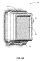
- FIG. 5A is a perspective view of one embodiment of the housing door.
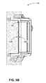
- FIG. 5B is a cross sectional view of the housing door, according to the embodiment shown in FIG. 5A .
- FIG. 6A is a perspective view of another embodiment of the door.
- FIG. 6B is a cross sectional view of the door, according to the embodiment shown in FIG. 6A .
- a camera system includes a camera and a housing that is structured to enclose the camera.
- the camera includes a touch-sensitive surface (e.g., a touchscreen) that can be used to receive user input.
- the camera housing includes a touch-through membrane in a position that allows the membrane to substantially align with the touch-sensitive surface when the camera is placed in the housing. The membrane transfers a user's gestures so that any touch gestures that are performed on the exterior surface of the membrane are transferred to the touch-sensitive surface.
- the camera housing may be divided into a first housing portion and a second housing portion that is moveably coupled to the first housing portion.
- the first housing portion is structured to receive the camera, and the second housing can be moved between an open and closed position.
- the camera is inserted into the first housing portion while the second housing portion is in the open position, and the second housing portion can then be moved into the closed position to enclose the camera in the housing.
- the touch-through membrane is mounted on the second housing portion so that the membrane substantially aligns with the touch-sensitive surface when the second housing portion is moved into the closed position.
- a compressible structure between the touch-through membrane and the camera housing.
- the compressible structure presses the membrane against the touch-sensitive surface so that the interior surface of the membrane is in physical contact with the touch-sensitive surface. This improves responsiveness when a user interacts with the touch-sensitive surface through the membrane.
- the compressible structure may also form a waterproof seal around the edges of the touch-through membrane, which prevents water damage to the camera when the camera is used to capture physical activities that take place near water, such as surfing or diving.
- a camera system includes a camera and a camera housing for enclosing the camera.
- the camera can be configured as a still picture camera, a moving picture camera (e.g., video), or both, and may be selectable between different operational modes.
- FIGS. 1A-1B illustrate various views of the camera system in accordance with one embodiment.
- the camera system includes, among other components, a first housing portion 102 and a second housing portion 104 (i.e. door 104 ), collectively referred to herein as the housing 100 .
- the first housing portion 102 includes a front face with four sides (i.e. a top side, bottom side, left side, and right side) structured to form a cavity that receives a camera 110 (e.g. a still camera or video camera).
- a second housing portion 104 (or door 104 ) detachably couples with the first housing portion 102 opposite the front face of the first housing portion 102 .
- the first housing portion 102 and second housing portion 104 are collectively structured to enclose the camera 110 within the cavity when the second housing portion 104 is secured to the first housing portion 102 in a closed position.
- the camera housing 100 encloses and protects the camera 110 .
- the camera housing 100 is particularly advantageous when using the camera 110 during periods of physical activity when the camera 110 may be susceptible to damage. For example, without the housing 100 , the camera 110 may become scratched or otherwise damaged when used during physical activity.
- the camera 110 is removable from the housing 100 so that if the housing 100 becomes scratched or damaged, it can be easily replaced at a much lower cost than replacing the camera 110 itself.
- the camera 110 and camera housing 100 have a small form factor (e.g., a height of approximately 4 to 6 centimeters, a width of approximately 5 to 7 centimeters, and a depth of approximately 2 to 4 centimeters), and are lightweight (e.g., approximately 50 to 150 grams).
- the camera housing 100 can be rigid (or substantially rigid) (e.g., plastic, metal, fiberglass, etc.) or pliable (or substantially pliable) (e.g., leather, vinyl, neoprene, etc.).
- the camera housing 100 may be appropriately configured for use in various elements.
- the camera housing 100 may comprise a waterproof enclosure that protects the camera 110 from water when used, for example, while surfing or scuba diving.
- Portions of the camera housing 100 may include exposed areas to allow a user to manipulate buttons on the camera 110 that are associated with the camera functionality. Alternatively, such areas may be covered with a pliable material to allow the user to manipulate the input devices through the camera housing 100 .
- the top face of the camera housing 100 includes an outer shutter button 112 structured so that a shutter button of the camera 110 is substantially aligned with the outer shutter button when the camera 110 is secured within the camera housing 100 .
- the shutter button of the camera 110 is operationally coupled to the outer shutter button 112 so that pressing the outer shutter button 112 allows the user to operate the camera shutter button.
- the front face of the camera housing 100 includes a lens window 114 structured so that a lens of the camera 110 is substantially aligned with the lens windows 114 when the camera 110 is secured within the camera housing 100 .
- the lens window 114 can be adapted for use with either a conventional lens of the camera 110 , a wide angle lens, or any other specialized camera lens.
- the lens window 114 comprises a waterproof seal so as to maintain the waterproof aspect of the housing 100 .
- the camera housing 100 includes one or more securing structures 120 for securing the camera housing 100 to one of a variety of mounting devices.
- the camera housing 100 can be secured to a wrist strap that secures the camera to a user's wrist.
- the housing 100 couples to a helmet mount via the securing structure 120 for mounting the camera to a helmet.
- a car mount for mounting the camera to a car couples to the securing structure 120 .
- other type of mount, strap, or securing devices known to those of ordinary skill in the art couple to the securing structure 120 for securing the camera to various other apparatuses or body parts.
- the second housing portion 104 comprises a door 104 (shown in the open position in FIGS. 1A-1B ) that allows the camera 110 to be removed from the housing 100 .
- the door 104 of the housing 100 pivots around a hinge 130 that allows the door 104 to be opened or shut.
- a first fastening structure 140 located on the top face of the camera housing 100 detachably couples to a second fastening structure 142 on the door 104 of the housing 100 .
- the fastening structures 140 , 142 secure the door 104 to the first portion 102 of the camera housing 100 in a closed position when coupled.
- FIG. 2 illustrates the camera housing 100 with the door 104 secured in the shut position using the fastening structures 140 , 142 .
- the fastening structure 140 comprises a hook-shaped lateral bar and the fastening structure 142 comprises an L-shaped bar.
- the fastening structure 140 can pivot upwards to allow the door 104 to close and can then be pressed down around the fastening structure 142 to hold the door 104 in the closed position.
- fastening structures for securing the door 104 can include, for example, a button assembly, a buckle assembly, a clip assembly, a hook and loop assembly, a magnet assembly, a ball and catch assembly, and an adhesive assembly, or any other type of securing mechanism.
- the housing 100 includes a watertight seal so that the housing 100 is waterproof when the door 104 is in the closed position.
- the door 104 includes a sealing structure 105 positioned on edges of the door 104 .
- the sealing structure 105 provides a watertight seal between the first portion of the camera housing 102 and the door 104 when the first securing structure 140 on the top face of the camera housing 100 is coupled to the second securing structure 142 on the top edge of the door 104 .
- the door 104 detachably uncouples from the first housing portion 102 at the hinge 130 .
- the door 104 can be detachably uncoupled from the first housing portion 102 if the two components 102 , 104 can be easily separated without causing structural damage or aberration to either component 102 , 104 .
- FIG. 3 illustrates an example embodiment of the camera housing 100 with the door 104 uncoupled from the first housing portion 102 .
- an outer hinge structure 132 on the bottom edge of the door 140 detachably couples to an inner hinge structure 134 on the bottom edge of the first housing portion 102 to form the hinge 130 .
- the outer hinge structure 132 comprises one or more hook-shaped protrusions structured to securely fasten to a rod-shaped member of the inner hinge structure 134 .
- the rod-shaped member is part of the outer hinge structure 132
- the inner hinge structure 134 comprises one or more hook-shaped protrusions that can be fastened to the outer hinge structure 132 .
- FIGS. 5A through 6B An example of this embodiment is shown in FIGS. 5A through 6B .
- Other mechanisms for detachably coupling the door 104 to the first housing portion 102 may also be used in various other embodiments.
- the door 104 may be permanently attached to the first housing portion 102 .
- the door 104 of the camera housing 100 can have different shapes or sizes to accommodate cameras 110 of different thicknesses and shapes.
- FIGS. 4A-4B illustrate a camera 110 outside of the housing 100 , according to one embodiment.
- a camera body 402 forms the main structure of the camera 110 .
- a camera lens 404 on an exterior surface of the camera body 402 focuses light onto a sensor inside the camera.
- the camera 110 contains imaging electronics (including the sensor) that capture image data and process the captured image data into photographs and videos.
- the exterior of the camera body 402 also includes a touch-sensitive surface 406 that detects touch gestures and translates the touch gestures into input signals for imaging electronics and other electronic components of the camera 110 .
- the touch-sensitive surface 406 is a touchscreen that incorporates a display.
- the touchscreen 406 may be used to perform a variety of functions, such as viewing previously-captured and stored photographs and videos or changing various settings of the camera 110 .
- the touch-sensitive surface 406 includes a capacitive touch sensor that is capable of detecting multiple contact points simultaneously.
- the touch-sensitive surface 406 may include a resistive touch sensor or some other touch sensing technology.
- the camera body 402 is divided into a main body 402 A and a detachable expansion body 402 B.
- the main body 402 A supports the camera lens 404 and the imaging electronics
- the touch-sensitive surface 406 is structured on a surface of expansion body 402 B.
- the touch-sensitive surface 406 may alternatively be structured on a surface of the main body 402 A, either on the same surface as the camera lens 404 , on the opposite surface, or on one of the other surfaces of the main body 402 A.
- FIG. 5A is a perspective view of the door 104 , according to one embodiment.
- the door 104 includes a fastening structure 142 on its top edge (adjacent to its top face) and an outer hinge structure 132 on its bottom edge (adjacent to its bottom face).
- the fastening structure and outer hinge structure can be located on other edges.
- the fastening structure may be located on the top edge while the outer hinge structure is located on the bottom edge opposite the top edge.
- the housing door 104 also includes a touch-through membrane 502 that is positioned so that it substantially aligns with the touch-sensitive surface 406 of the camera 110 when the camera is inserted into the housing and the housing door 104 is in a closed position.
- the membrane 502 is positioned on the rear face of the housing door 104 and substantially aligns with the touch-sensitive surface 406 on the rear face of the camera 110 .
- the touch-through membrane 502 is substantially aligned with the touch-sensitive surface 406 if a significant portion of the surface 406 (e.g., 80%, 90%, 95%, 98%, 100%, or some other percentage of the area of the surface 406 ) can be accessed through the membrane 502 .
- the membrane 502 allows a user to interact with the touch-sensitive surface 406 through the touch-through membrane 502 while the camera 110 is enclosed in the housing 100 and the door is in the closed position 104 .
- the functionality of the membrane 502 is described in detail below with reference to FIG. 5B .
- a second sealing structure 504 is positioned between the touch-through membrane 502 and the housing door 104 to complement the sealing structure 105 at the edges of the housing door 104 that contact the first housing portion 102 .
- the second sealing structure 504 provides a watertight seal between the membrane 502 and the door 104 , and the two sealing structures 105 , 504 collectively seal the housing 100 to prevent water from entering the interior of the housing 100 and damaging the camera 110
- FIG. 5B is a cross-sectional view of the door 104 , according to the embodiment of FIG. 5A .
- the membrane 502 transfers the touch interactions to the touch-sensitive surface 406 via the interior side of the membrane 502 B.
- the membrane 502 may be made of a conductive material that can transfer the conductivity of the user's finger from the exterior side 502 A to the interior side 502 B and onto the touch-sensitive surface 406 .
- the membrane 502 may be a flexible material that transfers pressure applied to the exterior side 502 A onto the touch-sensitive surface 406 .
- the membrane 502 may have other properties that allow for the transfer of touch gestures from the exterior side 502 A to the touch-sensitive surface 406 .
- the housing door 104 may be detachably coupled to the first housing portion 102 (e.g., with hook-shaped protrusions). This allows the housing door 104 to be replaced with a different housing door that does not include a touch-through membrane 502 or sealing structures 105 , 504 .
- the ability to replace the housing door 104 is beneficial in situations where the touch-through membrane 502 is not needed, either because access to the touch-sensitive surface 406 is not desired or because the camera 110 does not include a touch-sensitive surface 406 (e.g., if a detachable expansion body 502 B without a touch-sensitive surface 406 is used, or if the detachable expansion body 502 B is omitted altogether). In these situations, it may be advantageous to use a housing door with different features, such as a housing door with a completely rigid rear face that provides more robust protection than the membrane 502 .
- the sealing structure 504 is used to adhere the touch-through membrane 502 directly to the door 104 , which limits the movement of the membrane 502 relative to the door 104 .
- the size of the gap can vary due to dimensional tolerances and process variation when manufacturing the camera housing 100 and the camera body 402 , and the presence of the gap can prevent the camera from remaining motionless inside the housing (e.g., the camera might rattle).
- a compressible structure can be added between the touch-through membrane 502 and the door 104 to reduce or eliminate the gap between the interior side of the membrane 502 B and the touch-sensitive surface 406 . An embodiment that includes a compressible structure in this position is described below with reference to FIGS. 6A-6B .
- FIG. 6A is a perspective view of the door 104 , according to another embodiment. Similar to the embodiment of FIGS. 5A-5B , the door 104 includes a touch-through membrane 502 that is positioned to substantially align with the touch-sensitive surface 406 of the camera 110 when the camera 110 is enclosed in the housing 100 and the door 104 is in the closed position. In this embodiment, the exterior side 502 A of the membrane is adhered to a compressible structure 602 , and the compressible structure 602 is adhered to the door 104 .
- the compressible structure 602 performs several functions including securing the camera in the housing 100 , enhancing the usability of the touch-sensitive surface 406 , and protecting the camera 110 from water, as described below with reference to FIG. 6B .
- the compressible structure 602 has a rectangular cross section and a substantially rectangular shape that follows the edge of the touch-through membrane 502 .
- the outer border of the touch-through membrane 502 is adhered to one surface of the compressible structure 602 , and the opposite surface of the structure 602 is adhered to the door 104 .
- the compressible structure 602 may have a different cross section or shape in embodiments where the housing 100 or camera 110 have a different shape or size than the housing 110 and camera 110 illustrated in the accompanying drawings.
- the first housing portion 102 can be structured to form a cavity that receives the camera 110 , and the camera 110 can be enclosed in the housing 100 by opening the door 104 , placing the camera 110 in the first housing portion 102 and moving the door 104 to the closed position.
- the compressible structure 602 presses against the back of the camera 110 and pushes the front of the camera 110 against the front of the first housing portion 102 . Since the compressible structure 602 can be compressed to a variety of thicknesses, the structure 602 can compensate for variations in the thickness of the camera 110 that may arise due to manufacturing tolerances.
- the structure 602 can compress to a larger thickness when the camera 110 is slightly thinner, and the structure 602 can compress to a smaller thickness when the camera 110 is slightly thicker.
- the compressible structure 602 holds the camera 110 securely against the first housing portion 102 regardless of any variations in the camera's thickness and prevents the camera 110 from rattling or making any other undesired movement.
- the structure 602 Since the touch-through membrane 502 is adhered to the compressible structure 602 , the structure 602 also presses the interior side 502 B of the membrane toward the touch-sensitive surface 406 of the camera 110 when the camera 110 is inside the housing 100 with the housing door 104 in the closed position and when the compressible structure 602 is compressed.
- the compressible structure 602 holds the membrane 502 in physical contact with the touch-sensitive surface 406 .
- the membrane 502 there is no need for the membrane 502 to stretch in order to fill a gap between its interior side 502 B and the touch-sensitive surface 406 .
- the physical contact between the touch-sensitive surface 406 and the membrane 502 beneficially increases the responsiveness of the touch-sensitive surface 406 when operated through the membrane 502 and reduces the amount of tension that is applied to the membrane 502 during normal use.
- a spacer (not shown in FIGS. 6A-6B ) is positioned on the interior side 502 B of the membrane.
- the spacer contacts with the camera 110 and holds the interior side 502 B of the membrane substantially close to the touch-sensitive surface 406 when the door 104 is in the closed position.
- the interior side 502 B is substantially close to the touch-sensitive surface 406 when there is a small gap separating the two components 406 , 502 B (e.g., 0.3 mm, 0.5 mm, 0.7 mm, 1 mm, etc.).
- the compressible structure 602 holds the camera 110 in place by pressing the spacer against the back of the camera 110 , which in turn pushes the front of the camera 110 against the front of the first housing portion 102 .
- Having a small gap between the membrane 502 and the touch-sensitive surface can prevent moisture from becoming trapped under the membrane 502 (e.g., in small bubbles pressed against the touch-sensitive surface 406 ).
- using the spacer to establish the small gap and also push the camera 110 forward adds security by preventing the camera 110 from making any unwanted movements within the housing 100 .
- the compressible structure 602 can be made of any material that substantially changes shape when pressure is applied.
- the compressible structure 602 is made of a waterproof material (e.g., rubber or waterproof foam) that forms a watertight seal between the touch-through membrane 502 and the door 104 .
- a waterproof material protects the camera 110 from water damage when the housing 100 is subjected to splashing or submerged in water, which beneficially allows a user to interact with the touch-sensitive surface 406 while capturing photographs or video of water-related physical activities such as surfing or diving.
- the compressible structure 602 may be made of a non-waterproof material (e.g., porous foam) to reduce manufacturing costs.
- the touch-sensitive surface 406 is structured into the housing 100 (e.g., the housing door 104 ) instead of the camera 110 .
- the touch-sensitive surface 406 may be aligned with a membrane 502 in a manner similar to the embodiments described above.
- the touch-sensitive surface 406 may be integrated into the exterior surface of the housing 100 in a manner that prevents water from damaging the touch sensing electronics that convert touch gestures into input signals for the camera 110 .
- the input signals may be transmitted to the camera 110 wirelessly, over a cable coupling to the camera 110 , or over some other type of electronic coupling.
- the housing 100 illustrated in the accompanying drawings is configured for use with a camera 110
- the principles described herein may be adapted to any electronic device with a touch-sensitive surface.
- the housing 100 and touch-through membrane 502 may be adapted for use with touch-sensitive surfaces on cell phones, music players, PDAs, GPS units, tablet computers, laptop computers, or other electronic devices.
- the housing 100 may be embodied as a single portion instead of the two housing portions 102 , 104 illustrated in the accompanying drawings.
- the housing 100 may be a single rigid enclosure with an opening that allows for the insertion and removal of an electronic device.
- the touch-through membrane 502 may be placed at any position on the housing 100 that allows the membrane 502 to substantially align with a touch-sensitive surface of the enclosed electronic device.
- the membrane may alternatively be placed on the front, sides, top, or bottom of the housing 100 to substantially align with a corresponding touch-sensitive surface.
- the housing 100 may also be adapted for use with devices that have a touch-sensitive surface that does not incorporate a display, such as a trackpad or touchpad.
- the housing 100 may be adapted for use with a laptop computer or a standalone touchpad peripheral that connects to a computer.
- the housing 100 may be used with a device that features a touch-sensitive surface with multiple regions.
- the device may be a personal digital assistant (PDA) with a first touch-sensitive region that incorporates a display (e.g., a touchscreen for displaying a user interface) and a second touch-sensitive region that does not incorporate a display (e.g., a trackpad for handwriting recognition).
- PDA personal digital assistant
- the touch-through membrane may overlap with the entire touch-sensitive surface or only some regions of the touch-sensitive surface.
- Coupled and “connected” along with their derivatives. It should be understood that these terms are not intended as synonyms for each other. For example, some embodiments may be described using the term “connected” to indicate that two or more elements are in direct physical or electrical contact with each other. In another example, some embodiments may be described using the term “coupled” to indicate that two or more elements are in direct physical or electrical contact. The term “coupled,” however, may also mean that two or more elements are not in direct contact with each other, but yet still co-operate or interact with each other. The embodiments are not limited in this context.
- the terms “comprises,” “comprising,” “includes,” “including,” “has,” “having” or any other variation thereof, are intended to cover a non-exclusive inclusion.
- a process, method, article, or apparatus that comprises a list of elements is not necessarily limited to only those elements but may include other elements not expressly listed or inherent to such process, method, article, or apparatus.
- “or” refers to an inclusive or and not to an exclusive or. For example, a condition A or B is satisfied by any one of the following: A is true (or present) and B is false (or not present), A is false (or not present) and B is true (or present), and both A and B are true (or present).
- any reference to “one embodiment” or “an embodiment” means that a particular element, feature, structure, or characteristic described in connection with the embodiment is included in at least one embodiment.
- the appearances of the phrase “in one embodiment” in various places in the specification are not necessarily all referring to the same embodiment.
Abstract
Description
Claims (20)
Priority Applications (1)
| Application Number | Priority Date | Filing Date | Title |
|---|---|---|---|
| US13/652,362 US9241096B2 (en) | 2012-10-15 | 2012-10-15 | Housing with touch-through membrane |
Applications Claiming Priority (1)
| Application Number | Priority Date | Filing Date | Title |
|---|---|---|---|
| US13/652,362 US9241096B2 (en) | 2012-10-15 | 2012-10-15 | Housing with touch-through membrane |
Publications (2)
| Publication Number | Publication Date |
|---|---|
| US20140104488A1 US20140104488A1 (en) | 2014-04-17 |
| US9241096B2 true US9241096B2 (en) | 2016-01-19 |
Family
ID=50475029
Family Applications (1)
| Application Number | Title | Priority Date | Filing Date |
|---|---|---|---|
| US13/652,362 Expired - Fee Related US9241096B2 (en) | 2012-10-15 | 2012-10-15 | Housing with touch-through membrane |
Country Status (1)
| Country | Link |
|---|---|
| US (1) | US9241096B2 (en) |
Cited By (1)
| Publication number | Priority date | Publication date | Assignee | Title |
|---|---|---|---|---|
| US20170207643A1 (en) * | 2016-01-19 | 2017-07-20 | Nexark, Inc. | Battery adaptor apparatus |
Families Citing this family (9)
| Publication number | Priority date | Publication date | Assignee | Title |
|---|---|---|---|---|
| US9182653B2 (en) * | 2013-10-02 | 2015-11-10 | Jordan Heilweil | Convertible mobile surveillance camera enclosure for selectively protecting camera dome |
| US10409621B2 (en) | 2014-10-20 | 2019-09-10 | Taser International, Inc. | Systems and methods for distributed control |
| US10192277B2 (en) | 2015-07-14 | 2019-01-29 | Axon Enterprise, Inc. | Systems and methods for generating an audit trail for auditable devices |
| JP1546038S (en) * | 2015-08-07 | 2016-03-22 | ||
| USD794697S1 (en) * | 2015-09-01 | 2017-08-15 | Avant Technology, Inc. | Expansion module for a camera |
| CA2967512A1 (en) * | 2016-05-13 | 2017-11-13 | Tactacam LLC | Camera system using interchangeable fixed lenses |
| JP2018106127A (en) * | 2016-12-28 | 2018-07-05 | 株式会社ミツトヨ | Lens system and variable focal length lens device |
| US11079659B2 (en) * | 2018-05-16 | 2021-08-03 | Arlo Technologies, Inc. | Sliding cover with inclined-plane seal for weather sealed consumer electronics device |
| US11197524B1 (en) * | 2021-07-15 | 2021-12-14 | Pioneer Square Brands, Inc. | Case for portable electronic computing device |
Citations (8)
| Publication number | Priority date | Publication date | Assignee | Title |
|---|---|---|---|---|
| US6571056B2 (en) * | 2001-01-10 | 2003-05-27 | Ricoh Company, Ltd. | Waterproof case for camera |
| US6646864B2 (en) * | 2001-11-19 | 2003-11-11 | Otter Products, Llc | Protective case for touch screen device |
| US20050167304A1 (en) * | 2001-03-21 | 2005-08-04 | Takashi Shimamura | Waterproof case for portable device |
| US7180735B2 (en) * | 2001-11-19 | 2007-02-20 | Otter Products, Llc | Protective enclosure and watertight adapter for an interactive flat-panel controlled device |
| US20100060747A1 (en) * | 2008-07-07 | 2010-03-11 | Woodman Nicholas D | Camera Housing With Integrated Expansion Module |
| US7679674B2 (en) * | 2005-08-16 | 2010-03-16 | Nikon Corporation | Camera housing |
| US20120262618A1 (en) * | 2011-04-14 | 2012-10-18 | Amphibian Labs Llc | Waterproof case for hand held computing device |
| US20120314354A1 (en) * | 2011-06-13 | 2012-12-13 | Treefrog Developments, Inc. Dba Lifeproof. | Housing For Encasing a Tablet Computer |
-
2012
- 2012-10-15 US US13/652,362 patent/US9241096B2/en not_active Expired - Fee Related
Patent Citations (8)
| Publication number | Priority date | Publication date | Assignee | Title |
|---|---|---|---|---|
| US6571056B2 (en) * | 2001-01-10 | 2003-05-27 | Ricoh Company, Ltd. | Waterproof case for camera |
| US20050167304A1 (en) * | 2001-03-21 | 2005-08-04 | Takashi Shimamura | Waterproof case for portable device |
| US6646864B2 (en) * | 2001-11-19 | 2003-11-11 | Otter Products, Llc | Protective case for touch screen device |
| US7180735B2 (en) * | 2001-11-19 | 2007-02-20 | Otter Products, Llc | Protective enclosure and watertight adapter for an interactive flat-panel controlled device |
| US7679674B2 (en) * | 2005-08-16 | 2010-03-16 | Nikon Corporation | Camera housing |
| US20100060747A1 (en) * | 2008-07-07 | 2010-03-11 | Woodman Nicholas D | Camera Housing With Integrated Expansion Module |
| US20120262618A1 (en) * | 2011-04-14 | 2012-10-18 | Amphibian Labs Llc | Waterproof case for hand held computing device |
| US20120314354A1 (en) * | 2011-06-13 | 2012-12-13 | Treefrog Developments, Inc. Dba Lifeproof. | Housing For Encasing a Tablet Computer |
Non-Patent Citations (1)
| Title |
|---|
| Purcell, K., "Optrix HD Sport Case Turns iPhone Into Extreme Sport Camera," GottaBe Mobile, Dec. 7, 2011, 5 Pages [online] [retrieved on Dec. 27, 2012] Retrieved from the internet <URL: http://www.gottabemobile.com/2011/12/07/optrix-hd-sport-case-turns-iphone-into-extreme-sport-camera/>. |
Cited By (2)
| Publication number | Priority date | Publication date | Assignee | Title |
|---|---|---|---|---|
| US20170207643A1 (en) * | 2016-01-19 | 2017-07-20 | Nexark, Inc. | Battery adaptor apparatus |
| US9806546B2 (en) * | 2016-01-19 | 2017-10-31 | Nexark, Inc. | Battery adaptor apparatus |
Also Published As
| Publication number | Publication date |
|---|---|
| US20140104488A1 (en) | 2014-04-17 |
Similar Documents
| Publication | Publication Date | Title |
|---|---|---|
| US9241096B2 (en) | Housing with touch-through membrane | |
| US11846129B2 (en) | Camera housing and draw latch | |
| US11714338B2 (en) | Camera housing | |
| US10025166B2 (en) | Swivel wrist mount | |
| US9033596B2 (en) | Camera mount vibration dampener | |
| US9122133B2 (en) | Camera mount for sports board | |
| US20170013924A1 (en) | Protective enclosure for an electronic device | |
| US9389487B2 (en) | Protective lens attachment | |
| US20160033996A1 (en) | Mobile terminal | |
| WO2010005975A1 (en) | Camera housing with integrated expansion module | |
| US20150370288A1 (en) | Protective enclosures for mobile computing devices | |
| US10536181B2 (en) | Providing a seal for a protective mobile device case | |
| CN101741932A (en) | Slide type portable terminal | |
| TW201536147A (en) | Protection case and electronic device using the same | |
| KR20160098871A (en) | Waterproof case and mobile terminal using the same | |
| JP2006242996A (en) | Waterproof case | |
| CN110133989B (en) | Intelligent host computer and intelligent wrist-watch of upset are slided to realization side direction | |
| JP4965154B2 (en) | Waterproof case | |
| KR20170035681A (en) | Mobile terminal assembly |
Legal Events
| Date | Code | Title | Description |
|---|---|---|---|
| AS | Assignment |
Owner name: JPMORGAN CHASE BANK, NATIONAL ASSOCIATION, AS ADMI Free format text: SECURITY AGREEMENT;ASSIGNOR:WOODMAN LABS, INC.;REEL/FRAME:029529/0747 Effective date: 20121221 |
|
| AS | Assignment |
Owner name: WOODMAN LABS, INC., CALIFORNIA Free format text: ASSIGNMENT OF ASSIGNORS INTEREST;ASSIGNORS:SAMUELS, RUDY L.;BARBIER, FABRICE;COONS, EVAN L.;AND OTHERS;SIGNING DATES FROM 20121115 TO 20121128;REEL/FRAME:030618/0778 |
|
| AS | Assignment |
Owner name: GOPRO, INC., CALIFORNIA Free format text: CHANGE OF NAME;ASSIGNOR:WOODMAN LABS, INC.;REEL/FRAME:032167/0510 Effective date: 20140204 |
|
| ZAAA | Notice of allowance and fees due |
Free format text: ORIGINAL CODE: NOA |
|
| ZAAB | Notice of allowance mailed |
Free format text: ORIGINAL CODE: MN/=. |
|
| STCF | Information on status: patent grant |
Free format text: PATENTED CASE |
|
| AS | Assignment |
Owner name: JPMORGAN CHASE BANK, N.A., AS ADMINISTRATIVE AGENT, ILLINOIS Free format text: SECURITY AGREEMENT;ASSIGNOR:GOPRO, INC.;REEL/FRAME:038184/0779 Effective date: 20160325 Owner name: JPMORGAN CHASE BANK, N.A., AS ADMINISTRATIVE AGENT Free format text: SECURITY AGREEMENT;ASSIGNOR:GOPRO, INC.;REEL/FRAME:038184/0779 Effective date: 20160325 |
|
| MAFP | Maintenance fee payment |
Free format text: PAYMENT OF MAINTENANCE FEE, 4TH YEAR, LARGE ENTITY (ORIGINAL EVENT CODE: M1551); ENTITY STATUS OF PATENT OWNER: LARGE ENTITY Year of fee payment: 4 |
|
| AS | Assignment |
Owner name: GOPRO, INC., CALIFORNIA Free format text: RELEASE BY SECURED PARTY;ASSIGNOR:JPMORGAN CHASE BANK, N.A., AS ADMINISTRATIVE AGENT;REEL/FRAME:055093/0631 Effective date: 20210122 Owner name: GOPRO, INC., CALIFORNIA Free format text: RELEASE OF PATENT SECURITY INTEREST;ASSIGNOR:JPMORGAN CHASE BANK, N.A., AS ADMINISTRATIVE AGENT;REEL/FRAME:055106/0434 Effective date: 20210122 |
|
| FEPP | Fee payment procedure |
Free format text: MAINTENANCE FEE REMINDER MAILED (ORIGINAL EVENT CODE: REM.); ENTITY STATUS OF PATENT OWNER: LARGE ENTITY |
|
| LAPS | Lapse for failure to pay maintenance fees |
Free format text: PATENT EXPIRED FOR FAILURE TO PAY MAINTENANCE FEES (ORIGINAL EVENT CODE: EXP.); ENTITY STATUS OF PATENT OWNER: LARGE ENTITY |
|
| STCH | Information on status: patent discontinuation |
Free format text: PATENT EXPIRED DUE TO NONPAYMENT OF MAINTENANCE FEES UNDER 37 CFR 1.362 |
|
| FP | Lapsed due to failure to pay maintenance fee |
Effective date: 20240119 |