US9252492B2 - Antenna tuning via multi-feed transceiver architecture - Google Patents
Antenna tuning via multi-feed transceiver architecture Download PDFInfo
- Publication number
- US9252492B2 US9252492B2 US13/597,910 US201213597910A US9252492B2 US 9252492 B2 US9252492 B2 US 9252492B2 US 201213597910 A US201213597910 A US 201213597910A US 9252492 B2 US9252492 B2 US 9252492B2
- Authority
- US
- United States
- Prior art keywords
- antenna
- signals
- phase shift
- signal
- frequency
- Prior art date
- Legal status (The legal status is an assumption and is not a legal conclusion. Google has not performed a legal analysis and makes no representation as to the accuracy of the status listed.)
- Active, expires
Links
Images


Classifications
-
- H—ELECTRICITY
- H01—ELECTRIC ELEMENTS
- H01Q—ANTENNAS, i.e. RADIO AERIALS
- H01Q9/00—Electrically-short antennas having dimensions not more than twice the operating wavelength and consisting of conductive active radiating elements
- H01Q9/04—Resonant antennas
- H01Q9/0407—Substantially flat resonant element parallel to ground plane, e.g. patch antenna
- H01Q9/0421—Substantially flat resonant element parallel to ground plane, e.g. patch antenna with a shorting wall or a shorting pin at one end of the element
-
- H—ELECTRICITY
- H01—ELECTRIC ELEMENTS
- H01Q—ANTENNAS, i.e. RADIO AERIALS
- H01Q5/00—Arrangements for simultaneous operation of antennas on two or more different wavebands, e.g. dual-band or multi-band arrangements
- H01Q5/30—Arrangements for providing operation on different wavebands
- H01Q5/307—Individual or coupled radiating elements, each element being fed in an unspecified way
- H01Q5/342—Individual or coupled radiating elements, each element being fed in an unspecified way for different propagation modes
- H01Q5/35—Individual or coupled radiating elements, each element being fed in an unspecified way for different propagation modes using two or more simultaneously fed points
Definitions
- Multi-band transceivers are widely used in many modern wireless communication devices (e.g., cell phones, wireless sensors, PDAs, etc.). Multi-band transceivers are able to transmit and receive electromagnetic radiation at a variety of different frequencies. For example, a dual-band mobile phone is able to transmit and receive signals at two frequencies, a quad-band mobile phone is able to transmit and receive signals at four frequencies, etc.
- Operation at more than one frequency is important in modern mobile communication devices.
- different wireless standards e.g., GSM, TMDA, CMDA, etc.
- GSM Global System for Mobile communications
- TMDA TMDA
- CMDA complementary metal-oxide-semiconductor
- TMDA TMDA
- CMDA complementary metal-oxide-semiconductor
- even the same wireless standards may use different frequencies within a region or more than one frequency within a region.
- different regions may operate on different bands. For example, in the United States a GSM network uses two bands (e.g., 850 MHz or 1900 MH), while Europe uses two other bands.
- FIG. 1 illustrates a block diagram of a transmitter system comprising a tunable multi-feed antenna configured to radiate electromagnetic radiation with a plurality of frequency characteristics.
- FIG. 2 illustrates a graph showing an exemplary antenna reflection coefficient as a function of frequency for a disclosed tunable multi-feed antenna.
- FIGS. 3A-3B illustrate an exemplary operation of a disclosed tunable multi-feed antenna.
- FIG. 4 illustrates an exemplary transmitter system having a control element configured to introduce a variable phase and/or amplitude to a plurality of signals provided to a tunable multi-feed antenna.
- FIG. 5 illustrates a block diagram showing a cascaded network representation of a disclosed multi-feed antenna having two antenna feeds.
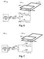
- FIGS. 6-8 illustrate different aspects of a tunable multi-feed planar inverted F antenna as provided herein.
- FIG. 9 is a flow diagram of an exemplary method for tuning a frequency of a tunable multi-feed antenna.
- FIG. 10 illustrates an example of a mobile communication device.
- a conventional multi-band transmitter comprises a bulky wideband antenna connected to a signal generator by way of one or more filters.
- the wideband antenna transmits over a broad frequency range, while the one or more filters operate to attenuate transmitted radio frequency signals that are outside of a desired frequency range.
- filters in conjunction with a wideband antenna allows the transceiver to operate at a plurality of different frequencies, such a transmitter architecture has drawbacks.
- the wideband antenna has a larger size and a lower efficiency than narrowband antennas.
- a large number of filters are used.
- the wideband antenna and filters increase the size, cost, and power consumption of the transmitter, which is undesirable in today's small, low power mobile communication devices.
- the present disclosure relates to an antenna configuration comprising a tunable multi-feed antenna that is configured to tune a transmitter's frequency of transmission.
- the antenna configuration comprises a tunable multi-feed antenna configured to wirelessly transmit electromagnetic radiation.
- a signal generator is configured to generate a plurality of signals, having a specific phase shift or amplitude difference between one another, which collectively correspond to a signal to be transmitted.
- the plurality of signals are provided to a plurality of antenna feeds connected to different spatial locations of the tunable multi-feed antenna.
- the specific phase shift and/or amplitude difference define an antenna input reflection coefficient that controls the frequency characteristics that the tunable multi-feed antenna operates at, such that by varying the phase shift and or amplitude difference, the frequency characteristics can be selectively adjusted.
- the disclosed tunable multi-feed antenna can mitigate the undesirable aspects of a conventional multi-band transmitter. It does so by allowing for a narrowband antenna, which has a smaller size and greater efficiency than a wideband antenna, to be used for transmitting at a plurality of frequencies. It also reduces the use of filters, since part of the RF filtering functionality is performed by the tunable multi-feed antenna itself.
- FIG. 1 illustrates a block diagram of a transmitter system 100 comprising a tunable multi-feed antenna 106 configured to radiate electromagnetic radiation over a plurality of frequency characteristics (e.g., transmit frequencies, frequency band size, etc.).
- frequency characteristics e.g., transmit frequencies, frequency band size, etc.
- the transmitter system 100 comprises a transmit module 102 configured to generate a plurality of radio frequency (RF) signals S 1 (A 1 , ⁇ 1 ), . . . , S n (A n , ⁇ n ), which collectively correspond to a signal-to-be-transmitted.
- the plurality of RF signals S 1 (A 1 , ⁇ 1 , . . . , S n (A n , ⁇ n ) are versions of a same RF signal having varying phases and/or amplitudes, such that the plurality of RF signals S 1 (A 1 , ⁇ 1 ), . . .
- the transmit module 102 is in communication the tunable multi-feed antenna 106 , which is configured to wirelessly transmit electromagnetic radiation over a radiation pattern spanning 360°.
- the tunable multi-feed antenna 106 may comprise a narrow-band antenna.
- the tunable multi-feed antenna 106 may comprise a wideband antenna or an ultra-wideband antenna, for example.
- the multi-feed antenna 106 comprises a plurality of antenna feeds 104 a , . . . , 104 n that are connected to the tunable multi-feed antenna 106 at spatially distinct input nodes IN 1 -IN n .
- 104 n are configured to concurrently provide the plurality of RF signals S 1 (A 1 , ⁇ 1 ), . . . , S n (A n , ⁇ n ) to the tunable multi-feed antenna 106 .
- the transmit module 102 comprises a signal generator 108 (e.g., an RF source) configured to generate the signal to be transmitted S tran .
- a single ended signal to be transmitted S tran is output from the signal generator 108 to a splitting element 110 configured to split the signal S tran into a plurality of RF signals S 1 , . . . , S n that are identical to one another.
- the plurality of RF signals S 1 , . . . , S n are provided to an adjustment module 112 configured to independently adjust the amplitude and/or phase of the RF signals S 1 , . . .
- the adjustment module 112 comprises one or more phase shifters, such as phase shifter 112 a or 112 b , configured to introduce a phase shift into one or more of the plurality of RF signals S 1 , . . . , S n .
- the adjustment module 112 comprises one or more vector modulators configured to adjust the phase and/or amplitude characteristics of the plurality of RF signals S 1 , . . . , S n .
- the splitting element 110 and/or the adjustment module 112 are comprised within a digital signal generator configured to generate a plurality of signals having a phase shift therebetween.
- Providing the plurality of RF signals S 1 (A 1 , ⁇ 1 ), . . . , S n (A n , ⁇ n ), with specific phases and/or amplitudes, to a single antenna causes the signals to collectively excite the multi-feed antenna 106 in a manner that controls how the antenna resonates (i.e., controls the frequency at which the antenna transmits radiation).
- the phase shift and/or amplitude difference between the plurality of RF signals S 1 (A 1 , ⁇ 1 ), . . . , S n (A n , ⁇ n ) define a transmit frequency at which the tunable multi-feed antenna transmits the signal to be transmitted S tran .
- the plurality of signals comprise a first RF signal S 1 (A 1 , ⁇ 1 ) having a first phase ⁇ 1 and a second RF signal S 2 (A 2 , ⁇ 2 ) having a second phase ⁇ 2 , wherein the first and second phases, ⁇ 1 and ⁇ 2 are phase shifted with respect to one another by a phase shift value ⁇ that causes the tunable multi-feed antenna 106 to resonate at a specific frequency.
- the tunable multi-feed antenna 106 may comprise three or more antenna feeds 104 a , . . . , 104 n , the transmitter system 100 can tune frequency characteristics comprising both the value and the size of a frequency band being transmitted on.
- the specific phases and/or amplitudes of the plurality of RF signals S 1 (A 1 , ⁇ 1 ), . . . , S n (A n , ⁇ n ) can be chosen to control the antenna input reflection coefficient ⁇ in of the antenna (i.e., the control power going to the antenna).
- the antenna input reflection coefficient ⁇ in By controlling the antenna input reflection coefficient ⁇ in , the frequency of the signal transmitted by the tunable multi-feed antenna 106 may be controlled. For example, when the input reflection coefficient ⁇ in is set to have a low reflection coefficient at a specific frequency, the tunable multi-feed antenna will transmit at that frequency. Alternatively, when the antenna input reflection coefficient ⁇ in is set to have a high reflection coefficient at a specific frequency, the tunable multi-feed antenna may not transmit at that frequency.
- FIG. 2 illustrates a graph 200 showing an exemplary antenna input reflection coefficient ⁇ in (y-axis) as a function of frequency (x-axis) for a disclosed tunable multi-feed antenna.
- a specific combination of phases and/or amplitudes of the plurality of signals causes the antenna input reflection coefficient ⁇ in to have a relatively low value, such that the tunable multi-feed antenna transmits at the first frequency f 1 (i.e., a small amount of the energy of the plurality of signals is reflected away from the multi-feed antenna).
- a specific combination of phases and/or amplitudes of the plurality of signals causes the antenna input reflection coefficient ⁇ in to have a relatively high value, such that the tunable multi-feed antenna does not transmit at the second frequency f 2 (i.e., a majority of the energy of the plurality of signals is reflected away from the multi-feed antenna). Therefore, by setting the phases and/or amplitude of signals provided to different antenna feeds of a same antenna, the antenna input reflection coefficient ⁇ in and therefore the frequency of a transmitted signal can be tuned.
- FIGS. 3A-3B illustrate an example of an operation of a disclosed tunable multi-feed antenna.
- FIG. 3A illustrates a block diagram of a transmitter system 300 having a multi-feed antenna 308 (e.g., a narrowband antenna) configured to operate over a frequency range comprising a plurality of distinct frequencies.
- a multi-feed antenna 308 e.g., a narrowband antenna
- the multi-feed antenna 308 comprises a planar inverted F antenna (PIFA).
- the PIFA comprises an excitable planar element 310 positioned above a ground plane 312 .
- the excitable planar element 310 has a length of x 1 and a width of and is separated from the ground plane 312 , which has a length of x 2 and a width of y 2 , by a height h.
- x 2 and y 2 are respectively larger than x 1 and y 1 , resulting in a ground plane 312 that is larger than the excitable planar element 310 .
- the excitable planar element 310 is connected to a signal generator 302 by way a first antenna feed 314 a and by way of a second antenna feed 314 b , which are connected to the multi-feed antenna 308 at a plurality of antenna ports.
- the first antenna feed 314 a is connected to the multi-feed antenna 308 at a first antenna port P 1 located at a first position and the second antenna feed 314 b is connected to the multi-feed antenna 308 at a second antenna port P 2 located at a second position.
- the antenna feeds, 314 a and 314 b are further connected to the signal generator 302 by way of a splitter element 304 and an adjustment module 306 comprising one or more phase shifters, 306 a and 306 b .
- the splitter element 304 is configured to receive a signal to be transmitted from the signal generator 302 and to generate a first and second output signals S 1 ( ⁇ ) and S 2 ( ⁇ ), which are identical to one another.
- the phase shifters 306 a and 306 b are configured to introduce an analog phase shift into the first and/or second output S 1 ( ⁇ ) and S 2 ( ⁇ ).
- the phase shifters 306 a and 306 b may comprise variable transmission lines configured to introduce a phase shift into the first output signal S 1 ( ⁇ ) and/or the second output signal S 2 ( ⁇ ).
- the phase shift introduced by an analog phase shifter may be controlled digitally (e.g., by a digital control word that controls the phase shift value(s)).
- a control element 316 is configured to independently control values of the phase shift and/or amplitude difference introduced by the phase shifters 306 a and 306 b so as to define a frequency of transmission.
- the control element 316 is configured to dynamically adjust the phase and/or amplitude of one or more signals, S 1 ( ⁇ ) and/or S 2 ( ⁇ ).
- the control element 316 may enable the multi-feed antenna 308 to operate in a plurality of operating modes that transmit signals over a wide spectrum of frequencies or can account for changes to the antenna caused by changes in a user environment (e.g., changing the position of a mobile phone relative to a user).
- control element 316 is configured to cause the phase shifters 306 a and 306 b to provide different combinations of phase shifts and/or amplitude differences corresponding to different wireless communication standards (e.g., a first operating mode corresponds to a first wireless communication standard, and a second operating mode corresponds to a second wireless communication standard, etc.).
- different wireless communication standards e.g., a first operating mode corresponds to a first wireless communication standard, and a second operating mode corresponds to a second wireless communication standard, etc.
- control element 316 may provide for different phase shifts that correspond to a frequency of operation of 800 MHz, 1800 MHz and 2.45 GHz in both free-space and in proximity to a user (e.g., in a normal coupling scenario under the effect of the user hand).
- FIG. 3B illustrates a graph 318 showing an antenna reflection coefficient ⁇ in (y-axis) as a function of frequency (x-axis) for different phase shift combinations.
- the different phase shift combinations correspond to a frequency of operation of 800 MHz, 1800 MHz and 2.45 GHz in both free-space (trendline 320 ) and proximity to a user (trendline 322 )(e.g., in a normal coupling scenario under the effect of the user hand).
- the control element 316 is configured to adjust the phase shifts introduced to signals S 1 and S 2 so that the multi-feed antenna 308 transmits signals at a frequency of 800 MHz.
- the control element will introduce different phase shifts depending on whether the transmitter system 300 is operating in free space (trendline 320 ) or in proximity to a user (trendline 322 ).
- the control element 316 is configured to adjust the phase shifts introduced to signals S 1 ( ⁇ ) and S 2 ( ⁇ ) so that the multi-feed antenna 308 transmits signals at a frequency of 1800 MHz.
- the control element 316 is configured to adjust the phase shifts introduced to signals S 1 ( ⁇ ) and S 2 ( ⁇ ) so that the multi-feed antenna 308 transmits signals at a frequency of 2.45 GHz.
- FIG. 4 illustrates a transmitter system 400 having a control element 414 configured to dynamically control one or more adjustment elements 406 a , 406 b within an adjustment module 404 to introduce a variable phase and/or amplitude to a plurality of signals provided from a transmit module 402 to a tunable multi-feed antenna 408 .
- the transmitter system 400 comprises a feedback loop 410 extending from the multi-feed antenna 408 to the control element 414 .
- the feedback loop 410 comprises a measurement element 412 configured to detect a frequency response comprising one or more frequency characteristics (e.g., a frequency of operation) of the multi-feed antenna 408 and to generate a measurement signal S meas based upon the detected frequency characteristics.
- the measurement signal S meas is provided to the control element, which in response to the received measurement signal S meas , selectively generates a control signal S CTRL configured to adjust the phase and/or amplitude introduced by one or more adjustment elements 406 a , 406 b so as to vary the frequency of operation of the multi-feed antenna 408 .
- the measurement element 412 may be comprised within transmitter system 400 so that the measurement signal S meas comprises a local feedback signal. In other examples, the measurement element 412 is comprised within a separate transceiver, so that the measurement signal S meas is received from another examples configured to receive the transmitted signal.
- the measurement element 412 is configured to generate a measurement signal S meas when changes in the operating frequency due to user interaction and/or other proximity effects are detected.
- the control element 414 is configured to receive the measurement signal S meas and based thereupon to adjust the phase shift and/or amplitude difference between the plurality of signals to account for changes in the operating frequency.
- the measurement element is configured to periodically measure the operating frequency of the multi-feed antenna 408 . Such a case can reduce power consumption of the measurement element 412 .
- control element 414 is configured to iteratively adjust the phase shift and/or amplitude difference between the plurality of signals S 1 (A 1 , ⁇ 1 ), . . . , S n (A n , ⁇ n ) using an iterative algorithm that changes the phase shift and/or amplitude difference until the measurement element 412 detects a desired frequency of transmission.
- the control element 414 can use an algorithm stored in a memory element 416 to blindly converge to a frequency of transmission by changing phase shift and/or amplitude difference applied to signals and by measuring a resulting frequency of transmission (via measurement element 412 ), until a desired frequency of transmission is achieved.
- control element 414 is configured to adjust the phases and/or amplitude of a plurality of signals based upon pre-determined phase and/or amplitude value combinations stored in a memory element 416 (e.g., comprising a lookup table).
- the memory element 416 comprises a plurality of phase shift and/or amplitude difference combinations associated with a plurality of transmit frequencies.
- the control element 414 accesses the memory element 416 to determine a phase shift and/or amplitude difference that is to be used.
- the memory element 416 may be configured to provide initial phase and/or amplitude values of a plurality of signals provided to a multi-feed antenna 408 , while an iterative algorithm is used to adjust the value to account for changes in a frequency response of the multi-feed antenna 408 (e.g., due to external use cases).
- FIG. 5 illustrates a block diagram 500 showing a cascaded network representation of a disclosed multi-feed antenna having two antenna feeds driven by a signal generator.
- the standard scattering matrix S A corresponds to transmit and receive channels when the two antenna feeds are terminated with 50 ⁇ . Cascading the multi-feed antenna with a 3 dB power splitter S 3dB and a phase-shifter S ⁇ results in an antenna input reflection coefficient ⁇ in .
- a three decibel power splitter has a scalar representation 502 of
- FIGS. 6-9 illustrate various ways of a tunable multi-feed antenna as provided herein. It will be appreciated that although the transceiver system in FIGS. 6-9 are illustrated as having two antenna feeds, that the disclosed multi-feed antenna is not limited to two antenna feeds. Rather, the disclosed multi-feed antenna may comprise any number of antenna feeds. Furthermore, although FIGS. 6-9 illustrate multi-feed antennas comprising PIFA antennas one of ordinary skill in the art will appreciate that the multi-feed antennas may comprise various types of antennas.
- the multi-feed antennas may comprise planar inverted-F wideband antennas (PIFA) and/or multiple-input/multiple-output (MIMO) wideband antennas.
- PIFA planar inverted-F wideband antennas
- MIMO multiple-input/multiple-output
- the multi-feed antennas may comprise MIMO wideband antennas and the receive antenna may comprise a wideband PIFA, for example.
- FIG. 6 illustrates an exemplary block diagram of a transmitter system 600 having a signal generator 602 connected to a multi-feed antenna 612 comprising a planar inverted F antenna (PIFA).
- PIFA planar inverted F antenna
- Signal generator 602 is configured to generate a differential signal corresponding to a signal to be transmitted.
- the differential signal is provided to a hybrid coupler 604 , which is configured to receive the differential signal and to generate a single ended signal that is output to a balanced power amplifier 606 configured to amplify the single ended signal.
- the signal generator 602 is compatible with conventional power amplifiers which are configured to receive a single ended signal.
- the output of the balanced power amplifier 606 is provided to a splitting element 608 configured to split the output of the balanced power amplifier 606 into identical first and second signals that are provided to the multi-feed antenna 612 by way of first and second antenna feeds 614 a and 614 b .
- the splitting element 608 may comprise a T-junction or a variable hybrid coupler.
- the first signal is provided along a first path to a first phase shift element 610 a and the second signal is provided along a second path to a second phase shift element 610 b .
- the first and second phase shift elements, 610 a and 610 b comprise analog phase shift elements configured to selectively introduce a phase shift into the first and/or second signals so as to generate a first phase shifted signal S 1 (A 1 , ⁇ 1 ) and/or a second phase shifted signal S 2 (A 2 , ⁇ 2 ).
- a phase shift between the first and second phase shifted signal enables tuning of the multi-feed antenna 612 , so that by controlling the relation between the two feeds (regarding phase in this case), one can change the operational band of the PIFA.
- the first phase shifted signal S 1 (A 1 , ⁇ 1 ) is provided to a first antenna feed 614 a connected to an excitable planar element 616 of the multi-feed antenna 612 at a first location.
- the second phase shifted signal S 2 (A 2 , ⁇ 2 ) is provided to a second antenna feed 614 b connected to the radiating planar element 616 at a second location.
- the first and second antenna feeds, 614 a and 614 b are connected to an area of the excitable planar element 616 having a high current density to provide better control of the tunable multi-feed antenna 612 .
- the first and second antenna feeds, 614 a and 614 b are connected to a corner of the excitable planar element 616 that has a high density of current.
- the second antenna feed 614 b comprises a ground pin of the PIFA connected between the excitable planar element 616 and a ground plane 618 .
- the second antenna feed enables phase shifting of the ground with respect to the antennas.
- neither of the first and second antenna feeds, 614 a and 614 b are connected to the ground plane 618 .
- phase shift elements may be implemented as various elements configured to introduce a phase shift into the signals.
- FIG. 7 illustrates some examples of a transmitter system 600 having phase shift elements comprising variable length transmission lines 702 .
- a splitting element 608 is configured to provide a first signal to a first variable length transmission line 702 a by way of a first path and a second signal to a second variable length transmission line 702 b by way of a second path.
- the first and second variable length transmission lines 702 a and 702 b are configured to introduce a variable phase shift into the first and second signals before they are provided to a multi-feed antenna 612 .
- FIG. 8 illustrates an exemplary block diagram of a transmitter system 800 having a balanced architecture that can reduce the RF front end complexity.
- Transmitter system 800 comprises a signal generator 802 configured to output a differential signal to a first hybrid coupler 804 .
- the first hybrid coupler 804 provides a single ended signal to a balanced power amplifier 806 having a second hybrid coupler 808 configured to split the received single ended signal into a differential signal.
- the differential signal is provided to a first signal path having a first power amplifier 810 a and to a second signal path having a second power amplifier 810 b within the balanced power amplifier 806 .
- the output of power amplifiers 810 a and 810 b can be provided directly to the multi-feed antenna 814 by way of first and second antenna feeds, 816 a and 816 b .
- a microstrip line 822 is positioned between the first and second signal paths, at a location downstream of power amplifiers 810 a , 810 b .
- the microstrip line 822 provides for improved control of the impedance of the tunable multi-feed antenna 814 .
- the signal generator 802 comprises an digital circuit configured to introduce a variable phase shift between branches of the differential signal (i.e., the signal generator 802 is configured to output a differential signal to which phase shifts have already been introduced into the signals).
- the balanced power amplifier 806 can additionally control the amplitude of the signals, S 1 (A 1 , ⁇ 1 ) and S 2 (A 2 , ⁇ 2 ), provided to the multi-feed antenna 814 .
- analog phase shift elements, 812 a and 812 b located downstream of the balanced power amplifier 806 are configured to selectively provide a variable phase shift to the signals, S 1 (A 1 , ⁇ 1 ) and S 2 (A 2 , ⁇ 2 ), provided to the multi-feed antenna 814 .
- a digital signal generator is configured to introduce a phase shift into the signals provided to the multi-feed antenna, S 1 (A 1 , ⁇ 1 ) and S 2 (A 2 , ⁇ 2 ), by way of a register shift operation.
- the shift register operation utilizes a shift register to introduce a phase shift to the first or second signal by way of a digitally controlled delay having a value that is a multiple of a clock period.
- a shift register is configured to introduce a first delay value to a first signal according to a first digital word, and to introduce second delay value to a second signal according to a second digital word. By varying the delays introduced between the first and second signals, the shift register can vary the phase shift between the first and second signals.
- FIG. 9 is a flow diagram of an exemplary method 1000 for tuning a frequency of a multi-feed antenna.
- a transceiver system having a tunable multi-feed antenna comprising a plurality of antenna feeds comprising a plurality of antenna feeds.
- the plurality of antenna feeds comprise a first antenna feed connected to a first spatial position of the multi-feed antenna and a second antenna feed connected to a second spatial position of the multi-feed antenna.
- the plurality of antenna feeds may comprise three or more antenna feeds respectively connected to different spatial positions of the multi-feed antenna.
- a signal generator operates to generate a plurality of signals, which collectively correspond to a signal to be transmitted.
- the plurality of signals are identical to one another.
- one or more phase shifters operate to introduce a phase shift and/or amplitude difference between the plurality of signals.
- the phase shift and/or amplitude difference define frequency characteristics of the signal to be transmitted.
- the frequency characteristics may comprise a frequency of transmission and/or a size of the frequency of transmission, for example.
- the phase shifters operate to provide a plurality of signals to the plurality of antenna feeds. For example, a first signal is provided to a first antenna feed and a second signal is provided to a second antenna feed.
- a measurement element operates to determine a frequency response of the multi-feed antenna.
- the frequency response may comprise a frequency of transmission.
- the adjustment elements operate to adjust an amplitude and/or phase of one or more of the plurality of signals to change the frequency characteristics of the transmitted signal.
- the adjusted amplitude and/or phase are then introduced by the adjustment elements into the plurality of signals at 906 .
- Steps 906 - 912 are iteratively performed (step 914 ) to achieve a desired frequency of transmission.
- FIG. 10 illustrates an example of a mobile communication device 1000 , such as a mobile phone handset for example.
- Mobile communication device 1000 includes at least one processing unit 1002 and memory 1004 .
- memory 1004 may be volatile (such as RAM, for example), non-volatile (such as ROM, flash memory, etc., for example) or some combination of the two.
- Memory 1004 may be removable and/or non-removable, and may also include, but is not limited to, magnetic storage, optical storage, and the like.
- computer readable instructions in the form of software or firmware 1006 which are configured to implement one or more examples provided herein, may be stored in memory 1004 .
- the computer readable instructions may be loaded in memory 1004 for execution by processing unit 1002 .
- Other peripherals, such as a power supply 1008 e.g., battery
- Processing unit 1002 and memory 1004 work in coordinated fashion along with a transmit module 1010 to wirelessly communicate with other devices by way of a wireless communication signal 1038 (e.g., that uses frequency modulation, amplitude modulation, phase modulation, and/or combinations thereof to communicate signals to another wireless device).
- a transmit antenna 1016 is coupled to transmit module 1010 by way of an adjustment module 1012 and a plurality of antenna feeds 1014 a , . . . , 1014 n .
- the transmit module 1010 is configured to output a plurality of identical signals to the adjustment module 1012 , which is configured to independently control phase and/or amplitude value of one or more of the identical signals.
- Respective signals, having different phases and/or amplitudes are then provided to different antenna feeds 1014 a , . . . , 1014 n , so that a plurality of signals having different phases and/or amplitudes are concurrently provided to the transmit antenna to drive the antenna to operate at a frequency that is dependent upon a phase shift and/or amplitude difference between the signals.
- the mobile communication device 1000 may include a number of interfaces that allow the mobile communication device 1000 to exchange information with the external environment. These interfaces may include one or more user interface(s) 1020 , and one or more device interface(s) 1022 , among others.
- user interface 1020 may include any number of user inputs 1024 that allow a user to input information into the mobile communication device 1000 , and may also include any number of user outputs 1026 that allow a user to receive information from the mobile communication device 1000 .
- the user inputs 1024 may include an audio input 1028 (e.g., a microphone) and/or a tactile input 1030 (e.g., push buttons and/or a keyboard).
- the user outputs 1026 may include an audio output 1032 (e.g., a speaker), a visual output 1034 (e.g., an LCD or LED screen), and/or tactile output 1036 (e.g., a vibrating buzzer), among others.
- Device interface 1022 may include, but is not limited to, a modem, a Network Interface Card (NIC), an integrated network interface, a radio frequency transmitter/receiver, an infrared port, a USB connection, or other interfaces for connecting mobile communication device 1000 to other devices.
- Device connection(s) 1022 may include a wired connection or a wireless connection.
- Device connection(s) 1022 may transmit and/or receive communication media.
Landscapes
- Variable-Direction Aerials And Aerial Arrays (AREA)
Abstract
Description
where S11=0, S12=[1 1]T, S21=[1 1]T and S22=[1 0 0 1]. The
Cascading the three decibel power splitter with the phase shifter results in an antenna input reflection coefficient Γin having a
Γin =s 11 +s 12 T(I 2 −S φ S A S φ S 22)−1 S φ S A S φ s 21
where I2 is a 2×2 identity matrix. Based upon the above equation, it is clear that the antenna input reflection coefficient Γin seen by the signal generator is function of the phase-shifts φ1 and φ2.
Claims (20)
Priority Applications (3)
| Application Number | Priority Date | Filing Date | Title |
|---|---|---|---|
| US13/597,910 US9252492B2 (en) | 2012-08-29 | 2012-08-29 | Antenna tuning via multi-feed transceiver architecture |
| DE102013108274.2A DE102013108274A1 (en) | 2012-08-29 | 2013-08-01 | Tuning an antenna over a multi-feed transceiver architecture |
| CN201310383235.9A CN103684501B (en) | 2012-08-29 | 2013-08-29 | Via the antenna tunings presenting transceiver architecture more |
Applications Claiming Priority (1)
| Application Number | Priority Date | Filing Date | Title |
|---|---|---|---|
| US13/597,910 US9252492B2 (en) | 2012-08-29 | 2012-08-29 | Antenna tuning via multi-feed transceiver architecture |
Publications (2)
| Publication Number | Publication Date |
|---|---|
| US20140062813A1 US20140062813A1 (en) | 2014-03-06 |
| US9252492B2 true US9252492B2 (en) | 2016-02-02 |
Family
ID=50098543
Family Applications (1)
| Application Number | Title | Priority Date | Filing Date |
|---|---|---|---|
| US13/597,910 Active 2034-05-31 US9252492B2 (en) | 2012-08-29 | 2012-08-29 | Antenna tuning via multi-feed transceiver architecture |
Country Status (3)
| Country | Link |
|---|---|
| US (1) | US9252492B2 (en) |
| CN (1) | CN103684501B (en) |
| DE (1) | DE102013108274A1 (en) |
Cited By (9)
| Publication number | Priority date | Publication date | Assignee | Title |
|---|---|---|---|---|
| US20130005278A1 (en) * | 2011-06-30 | 2013-01-03 | Motorola Mobility, Inc. | System and methods for adaptive antenna optimization |
| US10186769B1 (en) | 2017-07-20 | 2019-01-22 | Apple Inc. | Electronic device with shared control and power lines for antenna tuning circuits |
| US10218067B2 (en) | 2015-09-04 | 2019-02-26 | Elwha Llc | Tunable metamaterial systems and methods |
| US10236576B2 (en) | 2015-09-04 | 2019-03-19 | Elwha Llc | Wireless power transfer using tunable metamaterial systems and methods |
| US10249950B1 (en) * | 2017-09-16 | 2019-04-02 | Searete Llc | Systems and methods for reduced control inputs in tunable meta-devices |
| US10374669B2 (en) | 2016-08-31 | 2019-08-06 | Elwha Llc | Tunable medium linear coder |
| US10468776B2 (en) | 2017-05-04 | 2019-11-05 | Elwha Llc | Medical applications using tunable metamaterial systems and methods |
| US10826177B2 (en) | 2018-02-27 | 2020-11-03 | Apple Inc. | Electronic devices having phased antenna arrays for performing proximity detection operations |
| US10833381B2 (en) | 2017-11-08 | 2020-11-10 | The Invention Science Fund I Llc | Metamaterial phase shifters |
Families Citing this family (64)
| Publication number | Priority date | Publication date | Assignee | Title |
|---|---|---|---|---|
| US9912031B2 (en) | 2013-03-07 | 2018-03-06 | Cpg Technologies, Llc | Excitation and use of guided surface wave modes on lossy media |
| US9910144B2 (en) | 2013-03-07 | 2018-03-06 | Cpg Technologies, Llc | Excitation and use of guided surface wave modes on lossy media |
| US9941566B2 (en) | 2014-09-10 | 2018-04-10 | Cpg Technologies, Llc | Excitation and use of guided surface wave modes on lossy media |
| US10084223B2 (en) | 2014-09-11 | 2018-09-25 | Cpg Technologies, Llc | Modulated guided surface waves |
| US9882397B2 (en) | 2014-09-11 | 2018-01-30 | Cpg Technologies, Llc | Guided surface wave transmission of multiple frequencies in a lossy media |
| US9887587B2 (en) | 2014-09-11 | 2018-02-06 | Cpg Technologies, Llc | Variable frequency receivers for guided surface wave transmissions |
| US9887557B2 (en) | 2014-09-11 | 2018-02-06 | Cpg Technologies, Llc | Hierarchical power distribution |
| US10175203B2 (en) | 2014-09-11 | 2019-01-08 | Cpg Technologies, Llc | Subsurface sensing using guided surface wave modes on lossy media |
| US10027116B2 (en) | 2014-09-11 | 2018-07-17 | Cpg Technologies, Llc | Adaptation of polyphase waveguide probes |
| US10101444B2 (en) | 2014-09-11 | 2018-10-16 | Cpg Technologies, Llc | Remote surface sensing using guided surface wave modes on lossy media |
| US9893402B2 (en) | 2014-09-11 | 2018-02-13 | Cpg Technologies, Llc | Superposition of guided surface waves on lossy media |
| US10033198B2 (en) | 2014-09-11 | 2018-07-24 | Cpg Technologies, Llc | Frequency division multiplexing for wireless power providers |
| US10079573B2 (en) | 2014-09-11 | 2018-09-18 | Cpg Technologies, Llc | Embedding data on a power signal |
| US9960470B2 (en) | 2014-09-11 | 2018-05-01 | Cpg Technologies, Llc | Site preparation for guided surface wave transmission in a lossy media |
| US10074993B2 (en) | 2014-09-11 | 2018-09-11 | Cpg Technologies, Llc | Simultaneous transmission and reception of guided surface waves |
| US9859707B2 (en) | 2014-09-11 | 2018-01-02 | Cpg Technologies, Llc | Simultaneous multifrequency receive circuits |
| US10498393B2 (en) | 2014-09-11 | 2019-12-03 | Cpg Technologies, Llc | Guided surface wave powered sensing devices |
| US9887556B2 (en) | 2014-09-11 | 2018-02-06 | Cpg Technologies, Llc | Chemically enhanced isolated capacitance |
| US10001553B2 (en) | 2014-09-11 | 2018-06-19 | Cpg Technologies, Llc | Geolocation with guided surface waves |
| WO2016061536A1 (en) * | 2014-10-17 | 2016-04-21 | Wispry, Inc. | Tunable multiple-resonance antenna systems, devices, and methods for handsets operating in low lte bands with wide duplex spacing |
| US9923385B2 (en) | 2015-06-02 | 2018-03-20 | Cpg Technologies, Llc | Excitation and use of guided surface waves |
| US10193595B2 (en) | 2015-06-02 | 2019-01-29 | Cpg Technologies, Llc | Excitation and use of guided surface waves |
| US9857402B2 (en) | 2015-09-08 | 2018-01-02 | CPG Technologies, L.L.C. | Measuring and reporting power received from guided surface waves |
| CN108350854B (en) | 2015-09-08 | 2019-11-19 | Cpg技术有限责任公司 | The remote transmission of maritime power |
| US9997040B2 (en) | 2015-09-08 | 2018-06-12 | Cpg Technologies, Llc | Global emergency and disaster transmission |
| US9887585B2 (en) | 2015-09-08 | 2018-02-06 | Cpg Technologies, Llc | Changing guided surface wave transmissions to follow load conditions |
| US9921256B2 (en) | 2015-09-08 | 2018-03-20 | Cpg Technologies, Llc | Field strength monitoring for optimal performance |
| US10063095B2 (en) | 2015-09-09 | 2018-08-28 | CPG Technologies, Inc. | Deterring theft in wireless power systems |
| US9887558B2 (en) | 2015-09-09 | 2018-02-06 | Cpg Technologies, Llc | Wired and wireless power distribution coexistence |
| WO2017044281A1 (en) | 2015-09-09 | 2017-03-16 | Cpg Technologies, Llc | Guided surface waveguide probes |
| US10205326B2 (en) | 2015-09-09 | 2019-02-12 | Cpg Technologies, Llc | Adaptation of energy consumption node for guided surface wave reception |
| US9885742B2 (en) | 2015-09-09 | 2018-02-06 | Cpg Technologies, Llc | Detecting unauthorized consumption of electrical energy |
| EP3345276B1 (en) | 2015-09-09 | 2019-10-09 | CPG Technologies, LLC | Load shedding in a guided surface wave power delivery system |
| US9496921B1 (en) | 2015-09-09 | 2016-11-15 | Cpg Technologies | Hybrid guided surface wave communication |
| EA201890665A1 (en) | 2015-09-09 | 2018-09-28 | Сипиджи Текнолоджиз, Элэлси. | PROBES OF THE DIRECTED SURFACE WAVEGUIDE |
| EP3347091B1 (en) | 2015-09-09 | 2020-06-17 | CPG Technologies, LLC. | Power internal medical devices with guided surface waves |
| US9882436B2 (en) | 2015-09-09 | 2018-01-30 | Cpg Technologies, Llc | Return coupled wireless power transmission |
| US10027131B2 (en) | 2015-09-09 | 2018-07-17 | CPG Technologies, Inc. | Classification of transmission |
| US10498006B2 (en) | 2015-09-10 | 2019-12-03 | Cpg Technologies, Llc | Guided surface wave transmissions that illuminate defined regions |
| US10324163B2 (en) | 2015-09-10 | 2019-06-18 | Cpg Technologies, Llc | Geolocation using guided surface waves |
| US10103452B2 (en) | 2015-09-10 | 2018-10-16 | Cpg Technologies, Llc | Hybrid phased array transmission |
| US10408916B2 (en) | 2015-09-10 | 2019-09-10 | Cpg Technologies, Llc | Geolocation using guided surface waves |
| US10312747B2 (en) | 2015-09-10 | 2019-06-04 | Cpg Technologies, Llc | Authentication to enable/disable guided surface wave receive equipment |
| KR20180052669A (en) | 2015-09-10 | 2018-05-18 | 씨피지 테크놀로지스, 엘엘씨. | Geo-location using guided surface waves |
| KR20180051573A (en) | 2015-09-10 | 2018-05-16 | 씨피지 테크놀로지스, 엘엘씨. | Global time synchronization using surface wave |
| US10559893B1 (en) | 2015-09-10 | 2020-02-11 | Cpg Technologies, Llc | Pulse protection circuits to deter theft |
| EP3342024A1 (en) | 2015-09-10 | 2018-07-04 | CPG Technologies, LLC | Mobile guided surface waveguide probes and receivers |
| US10193229B2 (en) | 2015-09-10 | 2019-01-29 | Cpg Technologies, Llc | Magnetic coils having cores with high magnetic permeability |
| US10396566B2 (en) | 2015-09-10 | 2019-08-27 | Cpg Technologies, Llc | Geolocation using guided surface waves |
| US10408915B2 (en) | 2015-09-10 | 2019-09-10 | Cpg Technologies, Llc | Geolocation using guided surface waves |
| KR20180051604A (en) | 2015-09-11 | 2018-05-16 | 씨피지 테크놀로지스, 엘엘씨. | Enhanced guided surface waveguide probes |
| EP3338341B1 (en) | 2015-09-11 | 2019-05-29 | CPG Technologies, LLC | Global electrical power multiplication |
| WO2017182069A1 (en) | 2016-04-20 | 2017-10-26 | Huawei Technologies Co., Ltd. | Antenna arrangement and method for antenna arrangement |
| KR102429734B1 (en) * | 2016-08-18 | 2022-08-05 | 삼성전자 주식회사 | Apparatus and method for trasmitting signals with phase switching |
| US10581492B1 (en) | 2017-03-07 | 2020-03-03 | Cpg Technologies, Llc | Heat management around a phase delay coil in a probe |
| US10630111B2 (en) | 2017-03-07 | 2020-04-21 | Cpg Technologies, Llc | Adjustment of guided surface waveguide probe operation |
| US20200190192A1 (en) | 2017-03-07 | 2020-06-18 | Sutro Biopharma, Inc. | Pd-1/tim-3 bi-specific antibodies, compositions thereof, and methods of making and using the same |
| US10559866B2 (en) | 2017-03-07 | 2020-02-11 | Cpg Technologies, Inc | Measuring operational parameters at the guided surface waveguide probe |
| US10559867B2 (en) | 2017-03-07 | 2020-02-11 | Cpg Technologies, Llc | Minimizing atmospheric discharge within a guided surface waveguide probe |
| US10560147B1 (en) | 2017-03-07 | 2020-02-11 | Cpg Technologies, Llc | Guided surface waveguide probe control system |
| CN111937232B (en) * | 2018-02-22 | 2021-10-19 | 马萨诸塞大学 | Communication apparatus, communication method, and computer-readable storage hardware |
| CN109873680B (en) * | 2018-09-20 | 2021-08-03 | 华南理工大学 | Test system and test method of large-scale array antenna |
| CN113655275B (en) * | 2021-08-27 | 2023-06-02 | 中国科学院云南天文台 | Space radio environment measurement and control device and system |
| CN114040326B (en) * | 2021-11-10 | 2022-05-17 | 深圳市华创恒达科技有限公司 | Bluetooth low energy consumption device connection method capable of distance measurement reminding |
Citations (12)
| Publication number | Priority date | Publication date | Assignee | Title |
|---|---|---|---|---|
| WO1998026503A1 (en) | 1996-12-09 | 1998-06-18 | Qualcomm Incorporated | Efficient parallel-stage power amplifier |
| US6070090A (en) | 1997-11-13 | 2000-05-30 | Metawave Communications Corporation | Input specific independent sector mapping |
| US6072994A (en) * | 1995-08-31 | 2000-06-06 | Northrop Grumman Corporation | Digitally programmable multifunction radio system architecture |
| US20020126051A1 (en) * | 2000-11-09 | 2002-09-12 | Jha Asu Ram | Multi-purpose, ultra-wideband antenna |
| US20040214604A1 (en) * | 2002-04-19 | 2004-10-28 | Soon-Young Yoon | Apparatus and method for calibrating and compensating for distortion of an output signal in a smart antenna |
| WO2008049191A1 (en) | 2006-10-02 | 2008-05-02 | Sierra Wireless, Inc. | Centralized wireless communication system |
| CN101523759A (en) | 2006-10-02 | 2009-09-02 | 施克莱无线公司 | Centralized wireless communication system |
| US20090289861A1 (en) | 2008-05-20 | 2009-11-26 | Infineon Technologies Ag | Radio frequency communication devices and methods |
| US20110053646A1 (en) * | 2009-08-31 | 2011-03-03 | Motorola, Inc. | Scalable self-calibrating and configuring radio frequency head for a wireless communication system |
| US20110199279A1 (en) * | 2008-09-15 | 2011-08-18 | Tenxc Wireless Inc. | Patch antenna, element thereof and feeding method therefor |
| US20110215971A1 (en) * | 2010-03-05 | 2011-09-08 | Research In Motion Limited | Low frequency diversity antenna system |
| US8610832B2 (en) * | 2009-12-18 | 2013-12-17 | At&T Mobility Ii, Llc | System and method for broadcast station adjacency |
Family Cites Families (4)
| Publication number | Priority date | Publication date | Assignee | Title |
|---|---|---|---|---|
| US6570462B2 (en) * | 2000-11-08 | 2003-05-27 | Research In Motion Limited | Adaptive tuning device and method utilizing a surface acoustic wave device for tuning a wireless communication device |
| US7190974B2 (en) * | 2004-03-26 | 2007-03-13 | Broadcom Corporation | Shared antenna control |
| US8472904B2 (en) * | 2009-03-30 | 2013-06-25 | The Charles Stark Draper Laboratory, Inc. | Antenna with integrated tuning detection elements |
| US8948702B2 (en) * | 2009-06-15 | 2015-02-03 | Agc Automotive Americas R&D, Inc. | Antenna system and method for optimizing an RF signal |
-
2012
- 2012-08-29 US US13/597,910 patent/US9252492B2/en active Active
-
2013
- 2013-08-01 DE DE102013108274.2A patent/DE102013108274A1/en not_active Withdrawn
- 2013-08-29 CN CN201310383235.9A patent/CN103684501B/en not_active Expired - Fee Related
Patent Citations (13)
| Publication number | Priority date | Publication date | Assignee | Title |
|---|---|---|---|---|
| US6072994A (en) * | 1995-08-31 | 2000-06-06 | Northrop Grumman Corporation | Digitally programmable multifunction radio system architecture |
| US5872481A (en) | 1995-12-27 | 1999-02-16 | Qualcomm Incorporated | Efficient parallel-stage power amplifier |
| WO1998026503A1 (en) | 1996-12-09 | 1998-06-18 | Qualcomm Incorporated | Efficient parallel-stage power amplifier |
| US6070090A (en) | 1997-11-13 | 2000-05-30 | Metawave Communications Corporation | Input specific independent sector mapping |
| US20020126051A1 (en) * | 2000-11-09 | 2002-09-12 | Jha Asu Ram | Multi-purpose, ultra-wideband antenna |
| US20040214604A1 (en) * | 2002-04-19 | 2004-10-28 | Soon-Young Yoon | Apparatus and method for calibrating and compensating for distortion of an output signal in a smart antenna |
| WO2008049191A1 (en) | 2006-10-02 | 2008-05-02 | Sierra Wireless, Inc. | Centralized wireless communication system |
| CN101523759A (en) | 2006-10-02 | 2009-09-02 | 施克莱无线公司 | Centralized wireless communication system |
| US20090289861A1 (en) | 2008-05-20 | 2009-11-26 | Infineon Technologies Ag | Radio frequency communication devices and methods |
| US20110199279A1 (en) * | 2008-09-15 | 2011-08-18 | Tenxc Wireless Inc. | Patch antenna, element thereof and feeding method therefor |
| US20110053646A1 (en) * | 2009-08-31 | 2011-03-03 | Motorola, Inc. | Scalable self-calibrating and configuring radio frequency head for a wireless communication system |
| US8610832B2 (en) * | 2009-12-18 | 2013-12-17 | At&T Mobility Ii, Llc | System and method for broadcast station adjacency |
| US20110215971A1 (en) * | 2010-03-05 | 2011-09-08 | Research In Motion Limited | Low frequency diversity antenna system |
Non-Patent Citations (18)
| Title |
|---|
| A.-F. Sheta, S. F. Mahmoud, A Widely Tuneable Compact Patch Antenna, IEEE Antennas and Wireless Propagation Letters, vol. 7, No., pp. 40-42, 2008. |
| D. Peroulis, K. Sarabandi, L. P. B. Katehi, Design of reconfigurable slot antennas, IEEE Transactions on Antennas and Propagation , vol. 53, No. 2, pp. 645-654, Feb. 2005. |
| F. Ferrero, A Diallo,. C. Luxey, B. Derat, Phased two-element PIFA for adaptative pattern in UMTS handsets, IEEE International Workshop on Antenna Technology, 2009 ( iWAT 2009), pp. 1-4, Mar. 2-4, 2009. |
| J. Lin and T. Itoh, Active integrated antennas, IEEE Trans. Microwave Theory Tech., vol. 42, pp. 2186-2194, Dec. 1994. |
| J. Ollikainen, O. Kivekas, P. Vainikainen, Low-loss tuning circuits for frequency-tunable small resonant antennas, Symposium on Personal, Indoor and Mobile Radio Communications, vol. 4, No., pp. 1882-1887 vol. 4, Sep. 15-18, 2002. |
| J. T. Aberle, Oh Sung-Hoon, Auckland, D.T., Rogers, S.D., Reconfigurable antennas for wireless devices, IEEE Antennas and Propagation Magazine, vol. 45, No. 6, pp. 148-154, Dec. 2000. |
| K. A. Jose, V. K. Varadan, and V. V. Varadan, Experimental investigations on electronically tunable microstrip antennas, Microw. Opt.Technol. Lett., vol. 20, No. 3, pp. 166169, Feb. 1999. |
| Li Hui, Xiong Jiang, Yu Yufeng, He Sailing , A Simple Compact Reconfigurable Slot Antenna With a Very Wide Tuning Range, IEEE Transactions on Antennas and Propagation, , vol. 58, No. 11, pp. 3725-3728, Nov. 2010. |
| P. J. Rainville and F. J. Harackewiez, Magnetic tuning of a microstrip patch antenna fabricated on a ferrite film, IEEE Microw. and Guided Wave Lett., vol. 2, No. 12, pp. 483485, Dec. 1992. |
| P. K. Panayi, M. O. Al-Nuaimi, I. P. Ivrissimtzis, Tuning techniques for planar inverted-F antenna, Electronics Letters , vol. 37, No. 16, pp. 1003-1004, Aug. 2, 2001. |
| R. K. Mishra, S. S. Pattnaik, and N. Das, Tuning of microstrip antenna on ferrite substrate, IEEE Trans. Antennas Propag., vol. 41, No. 2, pp. 230233, Feb. 1993. |
| R. Valkonen, J. Holopainen, C. Icheln, P. Vainikainen, Broadband Tuning of Mobile Terminal Antennas, Second European Conference on Antennas and Propagation, 2007( EuCAP 2007), vol., No., pp. 1-6, Nov. 11-16, 2007. |
| S. Kawasaki, T. Itoh, A slot antenna with electronically tunable length, International Symposium on Antennas and Propagation Society, 1991. AP-S. Digest , vol., No., pp. 130-133 vol. 1, Jun. 24-28, 1991. |
| S. Maryam Mazinani and Hamid Reza Hassani, Superdirective Wideband Array of Planar Monopole Antenna With Loading Plate, IEEE antennas and wireless propagation letters, vol. 9 2010. |
| V. Radisic, S. T. Chew, Y. Qian, and T. Itoh, High-efficiency power amplifier integrated with antenna, IEEE Microwave Guided Wave Lett., vol. 7, pp. 39-41, Feb. 1997. |
| V. Radisic, Y. Qian, and T. Itoh, Novel architectures for high efficiency amplifiers for wireless applications, IEEE Trans. Microwave Theory Tech., vol. 46, , pp. 1901-1909, Nov. 1998. |
| W. R. Deal, V. Radisic, Y. Qian, and T. Itoh, Integrated antenna push-pull power amplifiers, IEEE Trans. Microwave Theory and Tech., vol. 47, pp. 1418-1425, Aug. 1999. |
| W. R. Deal, V. Radisic, Y. Qian, and T. Itoh, Novel push-pull integrated antenna transmitter front-end, IEEE Microwave Guided Wave Lett., vol. 8, pp. 405-407, Nov. 1998. |
Cited By (11)
| Publication number | Priority date | Publication date | Assignee | Title |
|---|---|---|---|---|
| US20130005278A1 (en) * | 2011-06-30 | 2013-01-03 | Motorola Mobility, Inc. | System and methods for adaptive antenna optimization |
| US9564676B2 (en) * | 2011-06-30 | 2017-02-07 | Google Technology Holdings LLC | System and methods for adaptive antenna optimization |
| US10218067B2 (en) | 2015-09-04 | 2019-02-26 | Elwha Llc | Tunable metamaterial systems and methods |
| US10236576B2 (en) | 2015-09-04 | 2019-03-19 | Elwha Llc | Wireless power transfer using tunable metamaterial systems and methods |
| US10374669B2 (en) | 2016-08-31 | 2019-08-06 | Elwha Llc | Tunable medium linear coder |
| US10468776B2 (en) | 2017-05-04 | 2019-11-05 | Elwha Llc | Medical applications using tunable metamaterial systems and methods |
| US10186769B1 (en) | 2017-07-20 | 2019-01-22 | Apple Inc. | Electronic device with shared control and power lines for antenna tuning circuits |
| US10249950B1 (en) * | 2017-09-16 | 2019-04-02 | Searete Llc | Systems and methods for reduced control inputs in tunable meta-devices |
| US10833381B2 (en) | 2017-11-08 | 2020-11-10 | The Invention Science Fund I Llc | Metamaterial phase shifters |
| US11367936B2 (en) | 2017-11-08 | 2022-06-21 | The Invention Science Fund I Llc | Metamaterial phase shifters |
| US10826177B2 (en) | 2018-02-27 | 2020-11-03 | Apple Inc. | Electronic devices having phased antenna arrays for performing proximity detection operations |
Also Published As
| Publication number | Publication date |
|---|---|
| CN103684501B (en) | 2016-06-29 |
| DE102013108274A1 (en) | 2014-03-06 |
| US20140062813A1 (en) | 2014-03-06 |
| CN103684501A (en) | 2014-03-26 |
Similar Documents
| Publication | Publication Date | Title |
|---|---|---|
| US9252492B2 (en) | Antenna tuning via multi-feed transceiver architecture | |
| JP4524674B2 (en) | Interrogator for RFID tag communication system | |
| CN109845034B (en) | Antenna element, antenna module, and communication device | |
| US20130244594A1 (en) | Agile and Adaptive Wideband MIMO Antenna Isolation | |
| US10177744B2 (en) | Wireless communication unit, integrated circuit and method for antenna tuning | |
| US8514134B2 (en) | MIMO antenna having parasitic elements | |
| KR101747644B1 (en) | Electronic device with impedance measurement circuitry | |
| US8373603B2 (en) | Dual feed antenna | |
| US7286094B2 (en) | Three-dimensional omni-directional antenna designs for ultra-wideband applications | |
| US6943746B2 (en) | Radio device and antenna structure | |
| EP2737574B1 (en) | Multi-output antenna | |
| US8862073B2 (en) | Configurable antenna structure | |
| US8159408B2 (en) | Method and system for software defined antenna control | |
| US20160094331A1 (en) | Multiplexers and Duplexers Having Active Cancellation for Improved Isolation between Transmit and Receive Ports | |
| US20090091508A1 (en) | Co-location insensitive multi-band antenna | |
| US20130244593A1 (en) | Agile and Adaptive Transmitter-Receiver Isolation | |
| US9837726B2 (en) | Multi-band active integrated MIMO antennas | |
| CN104508974B (en) | The reconfigurable doherty amplifier of multi-frequency multi-standard | |
| US9484978B2 (en) | System and method for communication with adjustable signal phase and power | |
| KR102422190B1 (en) | Apparatus and method for performing calibration on communication module | |
| US9634404B1 (en) | Beam steering multiband architecture | |
| US8068796B2 (en) | Power divider and dual-output radio transmitter | |
| EP3982554B1 (en) | Apparatus and method for correcting deviation between plurality of transmission channels | |
| JP2007312276A (en) | Antenna unit and communications device | |
| Wu et al. | 60-GHz CMOS artificial magnetic conductor on-chip 2× 2 monopole-antenna phased array RF receiving system with integrated variable-gain low-noise amplifier and phase shifter |
Legal Events
| Date | Code | Title | Description |
|---|---|---|---|
| AS | Assignment |
Owner name: INTEL MOBILE COMMUNICATIONS GMBH, GERMANY Free format text: ASSIGNMENT OF ASSIGNORS INTEREST;ASSIGNORS:ALRABADI, OSAMA NAFETH;TATOMIRESCU, ALEXANDRU DANIEL;KNUDSEN, MIKAEL BERGHOLZ;AND OTHERS;SIGNING DATES FROM 20120725 TO 20120829;REEL/FRAME:028952/0054 |
|
| AS | Assignment |
Owner name: INTEL DEUTSCHLAND GMBH, GERMANY Free format text: CHANGE OF NAME;ASSIGNOR:INTEL MOBILE COMMUNICATIONS GMBH;REEL/FRAME:037057/0061 Effective date: 20150507 |
|
| STCF | Information on status: patent grant |
Free format text: PATENTED CASE |
|
| MAFP | Maintenance fee payment |
Free format text: PAYMENT OF MAINTENANCE FEE, 4TH YEAR, LARGE ENTITY (ORIGINAL EVENT CODE: M1551); ENTITY STATUS OF PATENT OWNER: LARGE ENTITY Year of fee payment: 4 |
|
| AS | Assignment |
Owner name: INTEL CORPORATION, CALIFORNIA Free format text: ASSIGNMENT OF ASSIGNORS INTEREST;ASSIGNOR:INTEL DEUTSCHLAND GMBH;REEL/FRAME:061356/0001 Effective date: 20220708 |
|
| MAFP | Maintenance fee payment |
Free format text: PAYMENT OF MAINTENANCE FEE, 8TH YEAR, LARGE ENTITY (ORIGINAL EVENT CODE: M1552); ENTITY STATUS OF PATENT OWNER: LARGE ENTITY Year of fee payment: 8 |