US9258850B2 - Microwave heating device and image fixing apparatus using the same - Google Patents
Microwave heating device and image fixing apparatus using the same Download PDFInfo
- Publication number
- US9258850B2 US9258850B2 US13/686,668 US201213686668A US9258850B2 US 9258850 B2 US9258850 B2 US 9258850B2 US 201213686668 A US201213686668 A US 201213686668A US 9258850 B2 US9258850 B2 US 9258850B2
- Authority
- US
- United States
- Prior art keywords
- microwave
- electric field
- spaces
- standing
- heating chamber
- Prior art date
- Legal status (The legal status is an assumption and is not a legal conclusion. Google has not performed a legal analysis and makes no representation as to the accuracy of the status listed.)
- Expired - Fee Related, expires
Links
- 238000010438 heat treatment Methods 0.000 title claims abstract description 159
- 238000011144 upstream manufacturing Methods 0.000 claims abstract description 22
- 239000004020 conductor Substances 0.000 claims abstract description 15
- 230000004888 barrier function Effects 0.000 claims abstract description 4
- 230000005684 electric field Effects 0.000 claims description 218
- 239000000463 material Substances 0.000 claims description 34
- 239000004699 Ultra-high molecular weight polyethylene Substances 0.000 claims description 13
- 229920000785 ultra high molecular weight polyethylene Polymers 0.000 claims description 13
- 239000002245 particle Substances 0.000 claims description 8
- 238000003780 insertion Methods 0.000 claims description 7
- 230000037431 insertion Effects 0.000 claims description 7
- 238000010586 diagram Methods 0.000 description 24
- 229910052751 metal Inorganic materials 0.000 description 23
- 239000002184 metal Substances 0.000 description 23
- 238000000034 method Methods 0.000 description 12
- 230000001965 increasing effect Effects 0.000 description 11
- 230000000694 effects Effects 0.000 description 9
- -1 polytetrafluoroethylene Polymers 0.000 description 8
- 238000005192 partition Methods 0.000 description 7
- 229910045601 alloy Inorganic materials 0.000 description 6
- 239000000956 alloy Substances 0.000 description 6
- 230000008859 change Effects 0.000 description 6
- 230000008878 coupling Effects 0.000 description 5
- 238000010168 coupling process Methods 0.000 description 5
- 238000005859 coupling reaction Methods 0.000 description 5
- 239000004698 Polyethylene Substances 0.000 description 4
- 229910052782 aluminium Inorganic materials 0.000 description 4
- XAGFODPZIPBFFR-UHFFFAOYSA-N aluminium Chemical compound [Al] XAGFODPZIPBFFR-UHFFFAOYSA-N 0.000 description 4
- 238000002474 experimental method Methods 0.000 description 4
- 230000035699 permeability Effects 0.000 description 4
- 229920000573 polyethylene Polymers 0.000 description 4
- 229920001343 polytetrafluoroethylene Polymers 0.000 description 4
- 239000004810 polytetrafluoroethylene Substances 0.000 description 4
- 239000011347 resin Substances 0.000 description 4
- 229920005989 resin Polymers 0.000 description 4
- 238000004519 manufacturing process Methods 0.000 description 3
- 229910001369 Brass Inorganic materials 0.000 description 2
- RYGMFSIKBFXOCR-UHFFFAOYSA-N Copper Chemical compound [Cu] RYGMFSIKBFXOCR-UHFFFAOYSA-N 0.000 description 2
- BQCADISMDOOEFD-UHFFFAOYSA-N Silver Chemical compound [Ag] BQCADISMDOOEFD-UHFFFAOYSA-N 0.000 description 2
- 239000010951 brass Substances 0.000 description 2
- 238000006243 chemical reaction Methods 0.000 description 2
- 239000011248 coating agent Substances 0.000 description 2
- 238000000576 coating method Methods 0.000 description 2
- 239000000470 constituent Substances 0.000 description 2
- 229910052802 copper Inorganic materials 0.000 description 2
- 239000010949 copper Substances 0.000 description 2
- 239000011888 foil Substances 0.000 description 2
- PCHJSUWPFVWCPO-UHFFFAOYSA-N gold Chemical compound [Au] PCHJSUWPFVWCPO-UHFFFAOYSA-N 0.000 description 2
- 229910052737 gold Inorganic materials 0.000 description 2
- 239000010931 gold Substances 0.000 description 2
- 239000007769 metal material Substances 0.000 description 2
- 238000007747 plating Methods 0.000 description 2
- 239000010453 quartz Substances 0.000 description 2
- 238000007789 sealing Methods 0.000 description 2
- VYPSYNLAJGMNEJ-UHFFFAOYSA-N silicon dioxide Inorganic materials O=[Si]=O VYPSYNLAJGMNEJ-UHFFFAOYSA-N 0.000 description 2
- 229910052709 silver Inorganic materials 0.000 description 2
- 239000004332 silver Substances 0.000 description 2
- 238000010521 absorption reaction Methods 0.000 description 1
- 230000001464 adherent effect Effects 0.000 description 1
- 230000008901 benefit Effects 0.000 description 1
- 230000005540 biological transmission Effects 0.000 description 1
- 238000001354 calcination Methods 0.000 description 1
- 238000004364 calculation method Methods 0.000 description 1
- 239000000919 ceramic Substances 0.000 description 1
- 239000003086 colorant Substances 0.000 description 1
- 238000005265 energy consumption Methods 0.000 description 1
- 230000002708 enhancing effect Effects 0.000 description 1
- 230000004927 fusion Effects 0.000 description 1
- 230000007246 mechanism Effects 0.000 description 1
- 239000002923 metal particle Substances 0.000 description 1
- 150000002739 metals Chemical class 0.000 description 1
- 230000010363 phase shift Effects 0.000 description 1
- 230000008569 process Effects 0.000 description 1
- 230000000644 propagated effect Effects 0.000 description 1
- 230000001902 propagating effect Effects 0.000 description 1
- 230000001681 protective effect Effects 0.000 description 1
- 238000004088 simulation Methods 0.000 description 1
- 238000005245 sintering Methods 0.000 description 1
- 238000001228 spectrum Methods 0.000 description 1
- XLYOFNOQVPJJNP-UHFFFAOYSA-N water Substances O XLYOFNOQVPJJNP-UHFFFAOYSA-N 0.000 description 1
Images


Classifications
-
- H—ELECTRICITY
- H05—ELECTRIC TECHNIQUES NOT OTHERWISE PROVIDED FOR
- H05B—ELECTRIC HEATING; ELECTRIC LIGHT SOURCES NOT OTHERWISE PROVIDED FOR; CIRCUIT ARRANGEMENTS FOR ELECTRIC LIGHT SOURCES, IN GENERAL
- H05B6/00—Heating by electric, magnetic or electromagnetic fields
- H05B6/64—Heating using microwaves
- H05B6/6402—Aspects relating to the microwave cavity
-
- H—ELECTRICITY
- H05—ELECTRIC TECHNIQUES NOT OTHERWISE PROVIDED FOR
- H05B—ELECTRIC HEATING; ELECTRIC LIGHT SOURCES NOT OTHERWISE PROVIDED FOR; CIRCUIT ARRANGEMENTS FOR ELECTRIC LIGHT SOURCES, IN GENERAL
- H05B6/00—Heating by electric, magnetic or electromagnetic fields
- H05B6/64—Heating using microwaves
- H05B6/70—Feed lines
- H05B6/701—Feed lines using microwave applicators
-
- H—ELECTRICITY
- H05—ELECTRIC TECHNIQUES NOT OTHERWISE PROVIDED FOR
- H05B—ELECTRIC HEATING; ELECTRIC LIGHT SOURCES NOT OTHERWISE PROVIDED FOR; CIRCUIT ARRANGEMENTS FOR ELECTRIC LIGHT SOURCES, IN GENERAL
- H05B6/00—Heating by electric, magnetic or electromagnetic fields
- H05B6/64—Heating using microwaves
- H05B6/74—Mode transformers or mode stirrers
-
- H—ELECTRICITY
- H05—ELECTRIC TECHNIQUES NOT OTHERWISE PROVIDED FOR
- H05B—ELECTRIC HEATING; ELECTRIC LIGHT SOURCES NOT OTHERWISE PROVIDED FOR; CIRCUIT ARRANGEMENTS FOR ELECTRIC LIGHT SOURCES, IN GENERAL
- H05B6/00—Heating by electric, magnetic or electromagnetic fields
- H05B6/64—Heating using microwaves
- H05B6/78—Arrangements for continuous movement of material
Definitions
- the present invention relates to a microwave heating device with high heating efficiency.
- the present invention also relates to an image fixing apparatus which uses such microwave heating device with high heating efficiency for fusing developing particles (toner).
- An image fixing apparatus fuses a toner material onto a sheet (object to be printed) to fix an image onto a sheet.
- a conventional image fixing apparatus applies heat or pressure onto the sheet by means of a fusing roller to fuse toner onto the sheet.
- FIGS. 16A and 16B are conceptual diagrams showing a configuration of a microwave device disclosed in JP-A-2003-295692.
- a microwave device 100 includes a magnetron 110 generating a microwave, an input coupling converter 113 which input couples the microwave generated from the magnetron 110 to a resonator chamber 103 , a water reservoir 111 , and a circulator 112 .
- a coupling aperture 114 with a diaphragm is provided between the input coupling converter 113 and the resonator chamber 103 .
- the resonator chamber 103 has a side surface 109 provided with a passing portion 107 for passing and guiding a sheet 101 therethrough.
- the resonator chamber 103 has on the downstream side a terminal end slider 115 made of metal.
- the terminal end slider 115 is horizontally movable relative to the resonator chamber 103 , and extends into the resonator chamber 103 .
- FIG. 16B is a schematic perspective view of the resonator chamber 103 portion. A microwave generated from the magnetron 110 is led into the resonator chamber 103 .
- FIG. 16B shows the microwave in a substantially sine wave form.
- the resonator chamber 103 has the side surface 109 and a side surface 109 ′ which are opposite to each other and are provided with the passing portion 107 and a passing portion 107 ′, respectively.
- the sheet 101 passes through the passing portion 107 ′, and is led into the resonator chamber 103 . Then, the sheet 101 passes through the passing portion 107 opposite to the passing portion 107 ′, and is ejected therefrom.
- the moving direction of the sheet 101 is indicated by an arrow.
- the passing portions 107 and 107 ′ include therein a movable element 104 .
- the element 104 is a bar made of polytetrafluoroethylene (PTFE), and extends into the resonator chamber 103 .
- PTFE polytetrafluoroethylene
- the position of the element 104 can be longitudinally moved in the resonator chamber 103 .
- the position of the element 104 is moved to regulate the resonance conditions in the resonator chamber 103 . Therefore, the microwave absorption onto the sheet 101 can be enhanced.
- JP-A-2010-089351 discloses a technique using the microwave to dry ink discharged onto a media, in an inkjet printer.
- the inkjet printer disclosed in JP-A-2010-089351 uses a waveguide having a two-stage horseshoe shape which is bent in a center section and includes a reflection terminal member slidable within a range of 1 ⁇ 2 of a wavelength ⁇ of a supplied microwave in a terminal section.
- a standing microwave formed in the waveguide is normally formed in a cycle of ⁇ /2, so that uneven heating occurs according to a position.
- a peak position of energy of the standing microwave can be moved within a range of ⁇ /2 by moving the reflection terminal member.
- energy of the microwave at any position in the waveguide can be averaged, so that the ink can be prevented from being unevenly dried.
- the coupling aperture 114 with a diaphragm is provided between the input coupling converter 113 and the resonator chamber 103 .
- a standing microwave is formed in the resonator chamber 103 .
- the diaphragm portion has an inclined side surface which causes microwave reflection, thereby lowering transmission efficiency. That is, to lead a high-energy microwave into the resonator chamber 103 , it is necessary to generate higher microwave energy from the magnetron. As a result, the energy consumption is increased.
- An object of the present invention is to provide a microwave heating device capable of preventing the uneven heating from occurring and enhancing heating efficiency with as a simple configuration as possible.
- an object of the present invention is to provide a non-contact type image fixing apparatus with high heating efficiency by using such a microwave heating device for fusing developing particles.
- a microwave heating device includes a microwave generating portion outputting a microwave, and a conductive heating chamber guiding the microwave, and having a short-circuited terminal section of the microwave in a traveling direction, in which
- the heating chamber is divided into a plurality of spaces until a position of the terminal section along the traveling direction by a barrier section including a conductive material, and has an opening provided so that an object to be heated passes through the heating chamber in a direction non-parallel to the traveling direction of the microwave,
- phase shifters having different lengths with respect to the traveling direction and including a dielectric body having permittivity higher than air are inserted in the positions of the terminal sections toward the microwave generating portion, in the spaces except for at least one of the plurality of spaces, to mutually differentiate positions of bottoms of standing microwaves formed in the respective spaces with respect to the traveling direction,
- impedance adjusters having different lengths with respect to the traveling direction and including a dielectric body having permittivity higher than air are inserted in positions on an upstream side of a region passed by the object to be heated, in the spaces except for at least one of the plurality of spaces, to reduce differences in impedance in the spaces from an entrance of the heating chamber for receiving the microwave to the terminal section, including the phase shifters, and
- a square tubular waveguide including a conductive material makes a connection between a microwave output end of the microwave generating portion and the terminal section of the heating chamber, except for apart of the opening provided for passing the object to be heated.
- the phases of the standing microwaves formed in the respective spaces can be shifted in the traveling direction of the microwave, so that the positions of the bottoms and the positions of the peaks of the respective standing microwaves can be mutually shifted.
- the object to be heated is not sufficiently heated because when it passes through the one space, it passes through the position of the bottom of the standing microwave in that space, the bottom of the standing microwave is not formed in that position when it passes through the other space. That is, after the object to be heated passing through the all spaces, every position of the object to be heated has passed through the position of the standing microwave having the high energy amount.
- the impedance adjuster is inserted so as to reduce the differences of the impedance in the spaces generated because the phase shifters are inserted. Therefore, there is no large difference in energy amount of the microwave which enters each space.
- the heating chamber is divided into the plurality of spaces and the phase shifter and the impedance adjuster are just inserted in each space, so that the heating efficiency is improved with the very simple configuration.
- an outer shape of the phase shifter may be determined such that positions of the bottoms of the standing microwaves formed in the respective spaces are mutually shifted by ⁇ g/(2N) with respect to the traveling direction, in which N (N is 2 or more natural number) represents the number of the spaces, and ⁇ g represents an internal wavelength of the standing microwave formed in the waveguide of the heating chamber.
- the positions of the bottoms of the standing microwaves in the respective spaces can be most uniformly shifted, so that the uneven heating can be eliminated.
- a length of the phase shifter inserted into the space with respect to the traveling direction may be defined by an integral multiple of ⁇ g′/2, in which ⁇ g′ represents an internal wavelength of a standing microwave formed in the dielectric body of the phase shifter.
- the bottom of the standing microwave is formed in an end face position of the phase shifter on a side of the microwave generating portion in each space.
- the bottom of the standing microwave is formed in the terminal section. According to this method, the position of the bottom of the standing microwave can be intentionally shifted with respect to each space.
- phase shifter and the impedance adjuster may include the same material, and a total value of lengths of the phase shifter and the impedance adjuster provided in the space from the entrance of the heating chamber to the terminal section with respect to the traveling direction is equal to each other.
- phase shifter and the impedance adjuster may include ultra high molecular weight polyethylene.
- an electric field transformer including a dielectric body having permittivity higher than air in the space, in which
- the electric field transformer has a length larger than (4N ⁇ 3) ⁇ gz/8 but smaller than (4N ⁇ 1) ⁇ gz/8 with respect to the traveling direction, in which ⁇ gz represents an internal wavelength of a standing microwave formed in a dielectric body of the electric field transformer, and N (N>0) represents a natural number, and is provided on a side closer to the microwave generating portion than the insertion position of the impedance adjuster with respect to the traveling direction so as to include the bottom of the standing microwave.
- the electric field transformer is set in such a manner that its width is an odd multiple of 1 ⁇ 4 ⁇ gz and its face of a side of the terminal section of the heating chamber is positioned in the bottom of the standing microwave.
- the electric field intensity can be increased on the downstream side of the electric field transformer, that is, in the region passed by the object to be heated, compared with the upstream side.
- the temperature in the heating chamber can be rapidly raised in a short time.
- the electric field transformer may include the same material as that of the phase shifter and the impedance adjuster, and it may include ultra high molecular weight polyethylene.
- the production can be performed in a simple manner, and the manufacturer's cost can be expected to be reduced.
- an image fusing device includes the microwave heating device having the above characteristics, in which when a recording sheet attached with a developer passes through the opening and is heated in the heating chamber, the developer is fused on the recording sheet.
- the developer can be fused on the recording sheet in a short time, so that the image fusing apparatus without a mechanical fusing mechanism can be realized.
- the standing microwaves formed in the respective spaces only their phases can be shifted while the standing microwaves have almost the same energy amount (electric field intensity), so that the heating efficiency can be considerably improved with the simple configuration.
- FIG. 1 is a conceptual configuration diagram of a microwave heating device according to a first embodiment of the present invention.
- FIG. 2 is a perspective view showing a configuration of a heating chamber.
- FIG. 3 is a schematic plan view showing a detailed configuration of the heating chamber.
- FIG. 4 is a conceptual diagram of a standing microwave formed in the heating chamber.
- FIG. 5 is a conceptual diagram for describing a phase shift of the standing microwave formed in the space in the heating chamber.
- FIG. 6A is a conceptual diagram in a comparison example 1.
- FIG. 6B is a view showing an electric field distributed state of a standing microwave in the comparison example 1 with contour lines.
- FIG. 6C is a view showing a relationship between a position and electric field intensity in the electric field distributed state of the standing microwave in the comparison example 1 with a graph.
- FIG. 7A is a conceptual diagram in a comparison example 2.
- FIG. 7B is a view showing an electric field distributed state of a standing microwave in the comparison example 2 with contour lines.
- FIG. 7C is a view showing a relationship between a position and electric field intensity in the electric field distributed state of the standing microwave in the comparison example 2 with a graph.
- FIG. 8A is a conceptual diagram in an example 1.
- FIG. 8B is a view showing an electric field distributed state of a standing microwave in the example 1 with contour lines.
- FIG. 8C is a view showing a relationship between a position and electric field intensity in the electric field distributed state of the standing microwave in the example 1 with a graph.
- FIG. 9 is a conceptual configuration diagram of a microwave heating device according to a second embodiment of the present invention.
- FIG. 10 is a conceptual diagram showing an electric field distribution in a waveguide when an electric field transformer is set.
- FIG. 11A is a conceptual diagram for describing each electric field state in a waveguide when a terminal section in the waveguide is short-circuited.
- FIG. 11B is a conceptual diagram for describing an electric field state in a waveguide when a material having different permittivity is provided in a terminal section in the waveguide.
- FIG. 11C is a conceptual diagram for describing an electric field state in an upstream side of a dielectric body, the dielectric body, and in a downstream side of the dielectric body when a material having different permittivity is provided in a waveguide.
- FIG. 12A is a conceptual configuration diagram in a comparison example 3.
- FIG. 12B is a view showing an electric field distributed state of a standing microwave in the comparison example 3 with contour lines.
- FIG. 12C is a view showing a relationship between a position and electric field intensity in the electric field distributed state of the standing microwave in the comparison example 3 with a graph.
- FIG. 13A is a conceptual diagram in an example 2.
- FIG. 13B is a view showing an electric field distributed state of a standing microwave in the example 2 with contour lines.
- FIG. 13C is a view showing a relationship between a position and electric field intensity in the electric field distributed state of the standing microwave in the example 2 with a graph.
- FIG. 14 is a conceptual diagram of a tuner.
- FIG. 15A is a graph showing the waveform of a standing microwave when the electric field transformer is not interposed.
- FIG. 15B is a graph showing change in electric field intensity when the electric field transformer having a width of 0.06 ⁇ g′ is interposed.
- FIG. 15C is a graph showing change in electric field intensity when the electric field transformer having a width of 0.13 ⁇ g′ is interposed.
- FIG. 15D is a graph showing change in electric field intensity when the electric field transformer having a width of 0.25 ⁇ g′ is interposed.
- FIG. 155 is a graph showing change in electric field intensity when the electric field transformer having a width of 0.37 ⁇ g′ is interposed.
- FIG. 15F is a graph showing change in electric field intensity when the electric field transformer having a width of 0.44 ⁇ g′ is interposed.
- FIG. 15G is a graph showing the relation between the front-to-back ratio of the electric field transformer and the width of the electric field transformer.
- FIG. 15H is a table showing the relation between the front-to-back ratio of the electric field transformer and the width of the electric field transformer.
- FIG. 16A is a conceptual diagram showing a configuration of a conventional microwave device.
- FIG. 16B is a schematic perspective view of a resonator chamber portion of the conventional microwave device.
- FIG. 1 is a conceptual configuration diagram of a microwave heating device according to the present invention, and shows a state seen from one side.
- a microwave heating device 1 shown in FIG. 1 includes a microwave generating portion 3 which is a magnetron, a heating chamber 5 for heating an object to be heated with a microwave, and a tuner 7 between the microwave generating portion 3 and the heating chamber 5 .
- an isolator 4 is provided between the microwave generating portion 3 and the tuner 7 .
- the isolator 4 is a protective device which converts the electric power of the microwave reflected from the tuner 7 in the direction of the microwave generating portion 3 side into heat energy and stably operates the microwave generating portion 3 .
- the isolator 4 is not always necessary.
- this terminal 5 a may include the same metal material as that of the heating chamber 5 .
- the microwave generating portion 3 and the tuner 7 , and the tuner 7 and the heating chamber 5 are connected by square tubular frames made of conductive materials (such as metals), thereby confining the generated microwave.
- the heating chamber 5 has a slit 6 (corresponding to an “opening”).
- the heating chamber 5 is provided with the slit 6 for passing a sheet (corresponding to a “member to be heated”) therethrough.
- the sheet passes from the rear to the front in the direction of arrow d 1 .
- the heating chamber 5 also has, in the rear side surface, a slit opposing the slit 6 .
- the sheet enters into the heating chamber 5 through the slit in the rear side surface, is heated in the heating chamber 5 , and is ejected from the slit 6 in the front side surface to the outside of the heating chamber 5 .
- Toner particles adhere onto the surface of the sheet.
- the adherent toner particles are heated in the heating chamber 5 , and are fused onto the sheet.
- FIG. 2 is a perspective view showing a configuration of the heating chamber 5 .
- the heating chamber 5 has a square tubular shape surrounded by a conductor such as a metal while the heating chamber 5 is provided with the slit 6 and a microwave inlet 8 on its predetermined surfaces. That is, the heating chamber 5 is short-circuited with the conductor on a face positioned most downstream side with respect to the microwave generating portion 3 and opposed to the microwave inlet 8 .
- a constituent material of the heating chamber 5 includes a non-magnetic metal (having almost the same magnetic permeability as magnetic permeability of vacuum) such as aluminum, copper, silver or gold, an alloy having high electric conductivity, one or multi-layered plating having a thickness which is several times as large as a surface skin depth of the above metal or alloy, foil, surface-treated (including coating with a conductive material) metal, alloy such as brass, and resin.
- a non-magnetic metal having almost the same magnetic permeability as magnetic permeability of vacuum
- a non-magnetic metal such as aluminum, copper, silver or gold, an alloy having high electric conductivity, one or multi-layered plating having a thickness which is several times as large as a surface skin depth of the above metal or alloy, foil, surface-treated (including coating with a conductive material) metal, alloy such as brass, and resin.
- the heating chamber 5 has the microwave inlet 8 in the side surface on the microwave generating portion 3 side.
- the microwave inlet 8 is an opening for leading a microwave into the heating chamber 5 .
- the microwave outputted from the microwave generating portion 3 is led from the microwave inlet 8 into the heating chamber 5 in the direction indicated by arrow d 2 .
- the microwave inlet 8 has a substantially rectangular shape such that a is a dimension perpendicular to advancing direction d 1 of a sheet 10 and b is a dimension parallel to d 1 .
- the microwave propagating in the heating chamber 5 is in the basic mode (H10 mode or TE10 mode).
- the heating chambers 5 is divided into three-row spaces along the traveling direction d 2 of the microwave, as will be described in detail below with reference to FIG. 3 .
- Three-row spaces are provided in the present embodiment, but the number is not limited to three in realizing the present invention.
- the slit 6 preferably has a minimum size necessary for passing the sheet 10 to be heated therethrough. This is because when the slit 6 is excessively large, the introduced microwave leaks through the slit 6 , and the power of the microwave in the heating chamber 5 may be reduced.
- FIG. 3 is a schematic plan view showing a detailed configuration of the heating chamber 5 in the present embodiment.
- the heating chamber 5 has the square tubular shape surrounded by the conductor such as the metal, but here, a part of the inside of the heating chamber 5 is transparently illustrated for convenience of the description.
- the slit 6 is provided in the side face of the heating chamber 5 , and the sheet 10 can pass the inside of the heating chamber 5 through the slit 6 in the direction d 1 .
- the microwave generated from the microwave generating portion 3 can enter the heating chamber 5 in the direction d 2 from a left side in the drawing.
- the heating chamber 5 has partition plates 21 and 22 including the conductive material (metal in the present example) in the same direction as the traveling direction of the microwave, and it is divided into the three spaces such as spaces 11 , 12 , and 13 .
- each of the partition plates 21 and 22 has a gap (or slit) so that the sheet 10 can pass through in the direction d 1 .
- the partition plates be brought close to an inner wall of the heating chamber 5 as much as possible so that a passage communicating between the adjacent spaces does not exist except for the gap.
- phase shifters are inserted so as to mutually shift phases of standing microwaves traveling the respective spaces. More specifically, a phase shifter 31 is inserted in the space 11 , a phase shifter 32 is inserted in the space 12 , and a phase shifter not inserted in the space 13 .
- the phase shifter 31 is twice as long as the phase shifter 32 with respect to the direction d 2 .
- Each of the phase shifters 31 and 32 includes a material having high permittivity and inserted so as to block each space over its length.
- ultra-high-molecular-weight (UHMW) polyethylene is used as the material, but a resin material such as polytetrafluoroethylene, quartz, and high-permittivity material can be used.
- resin material such as polytetrafluoroethylene, quartz, and high-permittivity material can be used.
- they preferably include a material which is resistant to heat as much as possible. From the viewpoint of the processability and the cost, UHMV polyethylene is preferably used.
- impedance adjusters 33 and 34 are inserted in terminal sections in the spaces 12 and 13 , respectively.
- the impedance adjusters 33 and 34 include the same material as that of the phase shifters 31 and 32 .
- the impedance adjuster 33 to be inserted in the space 12 has the same length as that of the phase shifter 32 to be inserted in the same space 12 with respect to the direction d 2 .
- the impedance adjuster 34 to be inserted in the space 13 has the same length as that of the phase shifter 31 to be inserted in the space 11 with respect to the direction d 2 .
- the length in the direction d 2 is occasionally referred to as a “width” simply.
- FIG. 4 conceptually shows a state of the standing microwaves formed in the spaces 11 , 12 , and 13 when the microwave is introduced in the configuration in FIG. 3 .
- a width of the phase shifter 31 is ⁇ g′ and a width of the phase shifter 32 is ⁇ g′/2.
- ⁇ g′ represents a wavelength of the standing microwave formed in the same dielectric body as the phase shifters 31 and 32 (hereinafter, referred to as a “wavelength in the dielectric body”).
- the terminal end 5 a side is called “downstream”, and the microwave generating portion 3 side is called “upstream”.
- the phase shifters 31 and 32 are inserted in the spaces 11 and 12 , respectively so that their end faces (first faces) on the downstream side are positioned in the terminal section 5 a .
- a bottom of a standing microwave W 1 appears at a position 61 of an upstream end face (second face) of the phase shifter 31 , in the space 11 .
- a bottom of a standing microwave W 2 appears at a position 71 of an end face (second face) of the phase shifter 32 on the upstream side, in the space 12 .
- a bottom of a standing microwave W 3 appears at a position 81 of the terminal section 5 a , in the space 13 where the phase shifter is not inserted.
- a head section in which the supplied microwave is distributed into the spaces 11 , 12 , and 13 is shown as a “branching section 41 ”.
- the phases of the standing microwaves W 1 , W 2 , and W 3 existing in the spaces 11 , 12 , and 13 , respectively can be mutually shifted, so that positions of peaks of the standing microwaves W 1 , W 2 , and W 3 can be mutually shifted in the direction d 2 .
- the sheet 10 passes through the heating chamber 5 in the direction d 1 , it passes through a high-energy region while passing through the spaces 11 , 12 , and 13 .
- the sheet 10 is prevented from being unevenly heated.
- ⁇ g/6 a numerical value of ⁇ g/6 is provided because the heating chamber is divided into the three spaces, so that when it is divided into N in general, the phase should be shifted by ⁇ g/(2N) to most highly enhance the energy efficiency.
- the sheet 10 even when the sheet 10 is not sufficiently heated at the time of passing through the position of the bottom 62 in the space 11 , it can be sufficiently heated at the time of continuously passing through the spaces 12 and 13 because the positions in these spaces do not correspond to the bottoms of the standing microwaves.
- the phases of the standing microwaves W 1 , W 2 , and W 3 when the sheet 10 passes through in the direction d 1 , the uneven heating can be prevented with respect to the position in the direction d 2 . That is, by shifting the phases based on the condition in the equation 1, the most highly energy state can be realized in the heating chamber 5 .
- condition of the equation 1 need not be strictly established in realizing the effect of the present invention.
- the phase of the standing microwave is shifted in at least each of the spaces 11 , 12 , and 13 , the effect of preventing the uneven heating can be provided, compared with the case where the phase is not shifted. This will be described below based on an experiment result.
- the impedance adjusters 33 and 34 will be described. As described in the above, the phase shifters 31 and 32 are inserted in order to mutually shift the phases of the standing microwaves W 1 , W 2 , and W 3 in the spaces 11 , 12 , and 13 , respectively. Meanwhile, the impedance adjusters 33 and 34 are inserted in order to equalize (substantially equalize) the impedance in each space so that the microwave generated from the microwave generating portion can be equally (substantially equally) dispersed and inputted to the spaces 11 , 12 , and 13 .
- FIG. 6A shows a conceptual configuration diagram when the heating chamber 5 is simply divided into the three spaces 11 , 12 , and 13 with the partition plates 21 and 22 .
- FIGS. 6B and 6C show an electric field distribution of the standing microwave existing in each space when the microwave is introduced in the above state in the direction d 2 .
- FIG. 6B is a view showing an electric field distribution state of the standing microwave in a comparison example 1 with contour lines.
- FIG. 6C is a view showing a relationship between a position and electric field intensity in the comparison example 1 with a graph.
- microwave generation conditions from the microwave generating portion 3 are set such that output energy is 400 W, and an output frequency is 2.45 GHz.
- the heating chamber 5 and a waveguide are made of aluminum. This is similar in comparison examples 2 and 3, and examples 1 and 2 which will be described below.
- the microwave generating portion 3 A product manufactured by MICRO DEVICE CO. LTD (at present, MICRO ELECTRO CO. LTD) is used. As the generating conditions, an output energy is 400 W, and an output frequency is 2.45 GHz.
- the isolator 4 A product manufactured by MICRO DEVICE CO. LTD (at present, MICRO ELECTRO CO. LTD) is used.
- the heating chamber 5 An aluminum waveguide provided with the slit 6
- the sheet 10 A commercially available PPC (Plain Paper Copier) sheet called neutralized paper is used.
- the electric field intensity each of the standing microwaves W 1 , W 2 , and W 3 formed in the spaces is the same at the position in the direction d 2 . That is, the positions of the bottoms of the standing microwaves W 1 , W 2 , and W 3 are all almost the same, and the positions of the peaks thereof are also almost the same. Therefore, when the heating chamber 5 is heated in this configuration situation, the electric field intensity is different between the position of the bottom and the position of the peak, so that the uneven heating occurs.
- the electric field intensity of the standing microwave W 3 shows almost the same value as that of the standing microwave W 1 by the position, so that the standing microwave W 3 overlaps with the standing microwave W 1 on the graph.
- FIG. 7A is a conceptual configuration diagram in the comparison example 2. Specifically, a metal plate 45 having a width of ⁇ g/3 is inserted forward from the terminal section 5 a in the space 11 , and a metal plate 46 having a width of ⁇ g/6 is inserted forward from the terminal section 5 a in the space 12 .
- the space 13 does not have a metal plate, and it is configured such that the microwave terminates in the terminal section 5 a.
- the bottom of the standing microwave is formed at the position of the terminal section.
- the standing microwave formed in the space 11 can be designed so that the bottom is formed at a position ⁇ g/3 ahead from the terminal section 5 a .
- the metal plate 46 having the width of ⁇ g/6 is inserted forward from the terminal section 5 a in the space 12
- the standing microwave formed in the space 12 can be designed so that the bottom is formed at a position ⁇ g/6 ahead from the terminal section 5 a .
- FIGS. 7B and 7C show an electric field distribution of the standing microwave in each space when the microwave is introduced in the direction d 2 in the configuration of FIG. 7A .
- FIG. 7B is a view showing an electric field distribution state of the standing microwave in the comparison example 2 with contour lines.
- FIG. 7C is a view showing a relationship between a position and electric field intensity in the comparison example 2 with a graph.
- the contour drawing shown in FIG. 7B is a color drawing in fact, and configured with colors like the spectrum distribution. That is, when the electric field intensity is low, it is shown with a violet or blue color, and when the electric field intensity is high, it is shown with a red or orange color.
- the red line provided when the electric field intensity is high is displayed with a “blackish” color, and the line other than that color is displayed with a “whitish” color. That is, the parts in which many blackish lines are shown in a region surrounded by the white lines mean that the electric field intensity is very high.
- the electric field intensity is high in the space 12 , while the electric field intensity is low in the spaces 11 and 13 .
- the standing microwaves W 1 , W 2 , and W 3 formed in the spaces are mutually shifted in phase for sure, and the positions of the bottoms of the respective standing microwaves can be shifted.
- the electric field intensity differs among the standing microwaves, the uneven heating occurs based on the position after heated in this configuration.
- the phenomenon that the electric field intensity differs among the standing microwaves formed in the respective spaces is caused by the fact that the impedances are different among the spaces when viewed from the heating chamber entrance to the terminal section 5 a . That is, as a result of the insertion of the metal plates 45 and 46 in the terminal section, the impedance differs among the spaces 11 , 12 , and 13 , and as a result, the electric field intensity differs among the standing microwaves in the respective spaces.
- the present invention employs the configuration described with reference to FIGS. 3 to 5 to realize the situation in which the phases of the standing microwaves formed in the spaces are mutually differentiated while the impedance in the spaces is almost the same.
- This configuration will be described as an “example 1” with reference to an experiment result.
- FIG. 8A shows a conceptual configuration diagram of the example 1.
- the phase shifter 31 having the width of ⁇ g′ is inserted from the terminal section 5 a toward the upstream side, in the space 11 .
- the phase shifter 32 having the width of ⁇ g′/2 is inserted from the terminal section 5 a toward the upstream side, in the space 12 .
- Each of the phase shifters 31 and 32 includes ultra high molecular weight polyethylene serving as one of a material having high electric conductivity.
- the impedance adjuster 33 having the width of ⁇ g′/2 is inserted from the vicinity of the entrance toward the downstream side, in the space 12
- the impedance adjuster 34 having the width of ⁇ g′ is inserted from the vicinity of the entrance toward the downstream side, in the space 13 .
- the impedance adjusters 33 and 34 include the same material as that of the phase shifters 31 and 32 . That is, the phase shifter 32 and the impedance adjuster 33 include completely the same member in the present example, and the phase shifter 31 and the impedance adjuster 34 include completely the same member in the present example.
- FIGS. 8B and 8C show an electric field distribution of the standing microwaves in the respective spaces when the microwave is introduced in the direction d 2 in this state.
- FIG. 8B is a view showing an electric field distribution state of the standing microwave in the example 1 with contour lines.
- FIG. 8C is a view showing a relationship between a position and electric field intensity in the example 1 with a graph.
- the reason why the phase shifters 31 and 32 including the high dielectric body are introduced to mutually shift the phases of the standing microwaves is to easily adjust the impedance, in addition to mutually shift the phases. That is, as shown in the comparison example 2 (refer to FIG. 7A ), when the metal plates having different widths are inserted in the terminal sections, the phases of the standing microwaves can be mutually differentiated. However, in the case of the comparison example 2, the impedance differs among the spaces, and as a result, the electric field intensity differs among the standing microwaves, which is another factor causing the uneven heating. Therefore, when the impedance in the spaces can be almost equal under the configuration in FIG. 7A , the same effect as that of the example 1 can be expected. According to a method employed in this case, the impedance of each space is calculated under the condition that the metal plate is inserted, and the impedance adjuster is inserted to substantially equalize the impedance.
- phase shifter of the high dielectric body is employed instead of the metal plate, like the example 1, the impedance can be very easily adjusted.
- the phase shifters 31 and 32 , and the impedance adjusters 33 and 34 can include the same material, respectively, and in this case, the phase shifter 31 and the impedance adjuster 34 , and the phase shifter 32 and the impedance adjuster 33 can include the member having the same material and the same dimension.
- the uneven heating can be eliminated only by preparing the two ultra high molecular weight polyethylene members each having the width of ⁇ g′ and having a height and a length (length in the direction d 1 ) capable of sealing one space, and the two ultra high molecular weight polyethylene members each having a width of ⁇ g′/2 and having a height and a length (length in the direction d 1 ) capable of sealing one space.
- the effect of eliminating the uneven heating can be considerably enhanced by selecting the material and the dimension of the heating chamber 5 , and the material of the phase shifters 31 and 32 so as to satisfy the above equation 1.
- the impedance adjusters 33 and 34 are inserted in the vicinity of the entrance of the heating chamber 5 in FIG. 8A , but the impedance adjusters 33 and 34 only have to be inserted to positions on the further upstream side of the upstream side end face of the object to be heated at least when the object to be heated (such as the sheet 10 ) passes through.
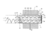
- FIG. 9 is a conceptual configuration diagram of a microwave heating device according to a second embodiment.
- the microwave heating device of the second embodiment differs from the apparatus of the first embodiment in that an electric field transformer 15 is further provided on the downstream side (side of the terminal section 5 a ) of the tuner 7 . More specifically, the electric field transformer 15 is provided in each of the spaces 11 , 12 , and 13 .
- the electric field transformer 15 is made of a high dielectric constant material.
- ultra high molecular weight (UHMW) polyethylene is used.
- a resin material such as polytetrafluoroethylene, quartz, and other high dielectric constant materials can be used.
- the electric field transformer 15 is preferably made of a hard-to-heat material where possible. From the viewpoint of the processability and the cost, UHMV polyethylene is preferably used.
- the electric field transformer 15 includes ultra high molecular weight polyethylene
- the electric field transformer 15 , the phase shifters 31 and 32 , and the impedance adjusters 33 and 34 can be all made up of the same material.
- the electric field transformer 15 has a width in the traveling direction d 2 of a microwave which is an odd multiple of ⁇ gz/4 ( ⁇ gz/4, 3 ⁇ gz/4, . . . ) where ⁇ gz is the wavelength of a standing microwave formed in the same dielectric as the electric field transformer 15 .
- the electric field transformer 15 has a width which is an odd multiple of ⁇ gz/4, so that the interposition effect of the electric field transformer 15 can be the highest.
- the interposition effect of the electric field transformer 15 can be obtained by setting the width of the electric field transformer 15 to satisfy later-described relational equations.
- the wavelength ⁇ gz of the standing microwave in the electric field transformer 15 coincides with the wavelength (wavelength in the dielectric body) ⁇ g′ of the standing microwaves in the phase shifters 31 and 32 .
- Equation 1 is established. From this relational equation, dielectric wavelength ⁇ g′ can be calculated.
- the electric field transformer 15 is fixed. More specifically, the electric field transformer 15 is provided in a position 20 which is a bottom of a standing microwave formed in the heating chamber 5 (each of the spaces 11 , 12 , and 13 ). More specifically, the electric field transformer 15 is provided in the position 20 in which the surface of the electric field transformer 15 on the terminal end 5 a side (downstream side) is at the bottom.
- the electric field transformer 15 has a higher dielectric constant than air, so that the wavelength of the standing microwave passing in the electric field transformer 15 becomes short. Accordingly, the electric field intensity of a standing microwave W′ on the downstream side (the terminal end 5 a side) from the electric field transformer 15 can be higher. In particular, when a width L of the electric field transformer 15 is set within the range of the following relational equation, the electric field intensity of standing microwave W′ can be significantly higher.
- N is a natural number.
- a high electric field intensity portion (peak) and a low electric field intensity portion (bottom) are caused according to distance in the direction from the terminal end 5 a toward the microwave generating portion 3 .
- the electric field transformer 15 at the bottom of the standing microwave, the electric field intensity of standing microwave W′ on the downstream side from the electric field transformer 15 can be higher. The toner fusibility can thus be improved.
- the slit 6 is provided on the downstream side from the electric field transformer 15 to pass the sheet 10 therethrough, thereby performing heating treatment based on power-increased standing microwave W′.
- the toner fusing time can be further shortened.
- the electric field intensity on the downstream side therefrom can be higher, which is also supported by the following theory.
- Equation 3 E i is the amplitude of an incident electric field intensity at the load end and E r is the amplitude of a reflected electric field intensity at the load end
- E y and H x at points on the Z axis of the waveguide are expressed by Equation 3.
- the a direction in FIG. 2 corresponds to the X axis
- the b direction therein corresponds to the Y axis
- the d 2 direction therein corresponds to the Z axis.
- E y corresponds to the Y axis component of an electric field
- H x corresponds to the X axis component of a magnetic field.
- Equation 3 Z 01 is a characteristic impedance, and ⁇ 1 is a propagation constant.
- a region I includes an atmosphere, and a region II is filled with the dielectric short-circuited at a terminal end c as an impedance Z R .
- E i1 is the incident electric field intensity of the region I
- E r1 is the reflected electric field intensity of the region I
- E i2 is the incident electric field intensity of the region II
- E r2 is the reflected electric field intensity of the region II
- Equation 5 Equation 5 is established.
- the Z coordinate in the head position (on the microwave generating side) in the region II is 0, and the width of the region II in the Z axis direction is d.
- a equation 6 is established by solving the equation 5 for E i2 .
- Equation 7 ⁇ 1g is a complex component (phase constant) of a waveguide wavelength ⁇ 1g in the region I, and ⁇ 2g is a complex component (phase constant) of a waveguide wavelength ⁇ 2g in the region II.
- K is a constant.
- Equation 7 when ⁇ 2g d is an odd multiple of ⁇ /2, the electric field intensity of the region II is equal to the incident electric field intensity, and when ⁇ 2g d is an even multiple of ⁇ /2, the electric field intensity of the region II is 1/K of the incident electric field intensity.
- the boundary surface between the regions having different dielectric constants is at the antinode of the electric field, the electric field intensities of the regions on both sides of the boundary surface are equal.
- the boundary surface between the regions having different dielectric constants is at the node of the electric field, the electric field intensities of the regions on both sides of the boundary surface are inversely proportional to the ratio between phase constants ⁇ g of the regions.
- the waveguide is filled with the dielectric having a thickness of ⁇ 2g /4 on the downstream side from a reference surface a (region II), and a short-circuited surface c is then placed at the distance of ⁇ 1g /4 on the downstream side of the region II from b (region III). Equation 8 is thus established.
- E I , E II , and E III indicate electric field intensities in the regions I, II, and III, respectively.
- the electric field intensity of the region III is K times the electric field intensity of the region I. That is, by interposing the dielectric having a thickness of ⁇ 2g /4, that is, the electric field transformer 15 , the electric field intensity on the upstream side therefrom is amplified to be propagated to the downstream side.
- the constant K is defined by Equation 10.
- FIG. 12A is a conceptual configuration diagram of a comparison example 3, and shows a state in which the electric field transformer 15 ( 15 a , 15 b , 15 C) including ultra high molecular weight polyethylene is inserted in each of the spaces 11 , 12 , and 13 , compared with the configuration of the comparison example 1.
- a width of the electric field transformer 15 is ⁇ g′/4.
- FIGS. 12B and 12C show an electric field distribution of the standing microwaves in the respective spaces when the microwave is introduced in the direction d 2 in this state.
- FIG. 123 is a view showing an electric field distribution state of the standing microwave in the comparison example 3 with contour lines.
- FIG. 12C is a view showing a relationship between a position and electric field intensity in the comparison example 3 with a graph.
- the comparison example 1 FIG. 6C
- the comparison example 3 FIG. 12C
- the space is simply divided into three, similar to the comparison example 1, the phases of the standing microwaves W 1 , W 2 , and W 3 formed in the spaces 11 , 12 , and 13 , respectively are not shifted, and the positions of the bottoms of the standing microwaves are almost the same in the direction d 2 . Therefore, the uneven heating occurs when the heating is performed in this state.
- FIG. 13A is a conceptual configuration diagram of an example 2, and shows a state in which the electric field transformer 15 ( 15 a , 15 b , 15 C) including ultra high molecular weight polyethylene is inserted in each of the spaces 11 , 12 , and 13 , compared with the configuration of the example 1.
- a width of the electric field transformer 15 is ⁇ g′/4.
- the phase shifters 32 and 33 , the impedance adjusters 33 and 34 , and the electric field transformers 15 a , 15 b , and 15 c are all made up of the same material, that is, ultra high molecular weight polyethylene.
- FIGS. 13B and 13C show an electric field distribution of the standing microwaves in the respective spaces when the microwave is introduced in the direction d 2 in this state.
- FIG. 13B is a view showing an electric field distribution state of the standing microwave in the example 2 with contour lines.
- FIG. 13C is a view showing a relationship between a position and electric field intensity in the example 2 with a graph.
- each space shows almost the same electric field intensity, and the positions of the bottoms of the standing microwaves are mutually shifted in the direction d 2 .
- the sheet 10 is passed through in this configuration in the direction d 1 , it can be almost uniformly heated in the direction d 2 .
- the electric field intensity of the standing microwave formed in each space can be considerably increased by the insertion of the electric field transformer 15 . That is, according to the example 2, the electric field intensity can be further increased while the bottoms of the standing microwaves W 1 , W 2 , and W 3 formed in the spaces 11 , 12 , and 13 , respectively, are shifted in the direction d 2 .
- heating efficiency can be further improved.
- FIG. 14 is a conceptual configuration diagram in the case where the E-H tuner is used as the tuner 7 .
- the tuner 7 has a configuration in which a first T-junction 11 is provided on a side face P 1 parallel to the traveling direction d 1 of the sheet, and a second T-junction 12 is provided on a side face P 2 vertical to the directions d 1 in a square tubular waveguide surrounded with a conductor such as a metal.
- a constituent material of the tuner 7 includes a non-magnetic metal (having almost the same magnetic permeability as magnetic permeability of vacuum) such as aluminum, copper, silver or gold, an alloy having high electric conductivity, one or multi-layered plating having a thickness which is several times as large as a surface skin depth of the above metal or alloy, foil, surface-treated (including coating with a metal material) metal, alloy such as brass, and resin.
- a non-magnetic metal having almost the same magnetic permeability as magnetic permeability of vacuum
- a non-magnetic metal such as aluminum, copper, silver or gold, an alloy having high electric conductivity, one or multi-layered plating having a thickness which is several times as large as a surface skin depth of the above metal or alloy, foil, surface-treated (including coating with a metal material) metal, alloy such as brass, and resin.
- the tuner 7 including the E-H tuner When the tuner 7 including the E-H tuner is provided between the microwave generating portion 3 and the heating chamber 5 , the power of the standing microwave formed in the heating chamber can be considerably increased. More specifically, after the incident microwave has been reflected at the terminal section 5 a of the heating chamber 5 , the reflected wave is reflected by the E-H tuner 7 toward the heating chamber 5 again. This reflection is repeated several times, so that the electric field of the standing microwave formed in the heating chamber 5 can be increased.
- the microwave is used for fusing toner onto the sheet.
- the present invention can be used for other typical applications in which abrupt heating is required in a short time (e.g., calcination and sintering of ceramics, chemical reaction requiring high temperature, and manufacturing of a wiring (conductive) pattern with toner as metal particles).
- the width of the electric field transformer 15 is preferably an odd multiple of ⁇ g′/4.
- the width of the electric field transformer 15 should satisfy at least the relational equations, and is desirably close to an odd multiple of ⁇ g′/4 where possible.
- impedance conversion is not performed. Therefore, the effect of increasing the electric field intensity on the later stage (terminal end 5 a ) side cannot be exhibited.
- a description will be given of this point with reference to an example.
- FIGS. 15A to 15F are graphs showing the electric field intensity in the heating chamber 5 when the microwave is introduced from the microwave generating portion 3 to the heating chamber 5 while the width of the electric field transformer 15 is changed, in the case where the heating chamber 5 has one space.
- the dielectric having the same width is interposed directly ahead of a short-circuited plate. This is performed for making the experimental conditions identical, and does not affect the effect of Examples.
- the magnitude of the electric field intensity in a position at the wave trough of the standing microwave is slightly varied, which is within the calculation error range.
- FIG. 15G is a graph showing change in the ratio between the magnitudes of electric field intensities on the upstream side and the downstream side of the electric field transformer 15 when the width of the electric field transformer 15 is changed.
- FIG. 15H is a table thereof.
- FIGS. 15A , 15 B, 15 C, 15 D, 15 E, and 15 F are graphs made when the widths of the electric field transformer 15 are 0, 6 mm, 13 mm, 25 mm, 37 mm, and 44 mm, respectively.
- the width of the electric field transformer 15 is 6 mm (this corresponds to 0.06 ⁇ g′).
- the electric field intensity 4.2.
- the electric field intensity 5.3.
- the electric field intensity is 1.26 times higher at the back than at the front of the electric field transformer 15 .
- the width of the electric field transformer 15 is 13 mm (this corresponds to 0.13 ⁇ g′).
- the electric field intensity 3.8.
- the electric field intensity 6.8.
- the electric field intensity is 1.79 times higher at the back than at the front of the electric field transformer 15 .
- the width of the electric field transformer 15 is 25 mm (this corresponds to 0.25 ⁇ g′).
- the electric field intensity 3.4.
- the electric field intensity 6.2.
- the electric field intensity is 1.82 times higher at the back than at the front of the electric field transformer 15 .
- the width of the electric field transformer 15 is 37 mm (this corresponds to 0.37 ⁇ g′).
- the electric field intensity 3.5.
- the electric field intensity 6.0.
- the electric field intensity is 1.7 times higher at the back than at the front of the electric field transformer 15 .
- the width of the electric field transformer 15 is 44 mm (this corresponds to 0.44 ⁇ g′).
- the electric field intensity 4.2.
- the electric field intensity 4.5.
- the electric field intensity is 1.1 times higher at the back than at the front of the electric field transformer 15 .
- the width of the electric field transformer 15 is 50 mm (this corresponds to 0.50 ⁇ g′)
- the upstream end point and the downstream end point of the electric field transformer 15 are both in the position at the wave trough of the standing microwave. Therefore, the electric field intensity is not changed on the downstream side and the upstream side of the electric field transformer 15 .
- a width L of the electric field transformer 15 is set to satisfy (4N ⁇ 3) ⁇ g′/8 ⁇ L ⁇ (4N ⁇ 1) ⁇ g′/8 by using the relational equations, that is, natural number N, so that the electric field intensity of the standing microwave on the downstream side of the electric field transformer 15 can be higher. Accordingly, the electric field intensity in the heating chamber 5 can be higher to greatly shorten time necessary for toner fusion.
- the electric field transformer 15 is inserted into each of the spaces 11 , 12 , and 13 in the region having the three spaces.
- the space in the vicinity of the entrance of the heating chamber 5 is not divided, and three spaces are formed by providing the partition plates 21 and 22 at a predetermined distance from the entrance to the downstream side.
- the electric field transformer 15 may be inserted in a predetermined region from the entrance which is not divided to the three spaces to the distance D in the direction d 2 .
- the phases are shifted by providing one space in which the phase shifter is not inserted, but the phases may be shifted by providing the phase shifters for all of the spaces.
- the impedance is adjusted by providing the one space in which the impedance adjuster is not inserted, but the impedance may be adjusted by providing the impedance adjusters for all of the spaces.
Abstract
Description
(4N−3) λg′/8<L<(4N−1) λg′/8
E x(z=d)=E i2 e −Y
|E III |=K|E I| [Equation 9]
Claims (18)
Applications Claiming Priority (2)
| Application Number | Priority Date | Filing Date | Title |
|---|---|---|---|
| JP2011-258579 | 2011-11-28 | ||
| JP2011258579A JP5536743B2 (en) | 2011-11-28 | 2011-11-28 | Microwave heating device and image fixing device using the same |
Publications (2)
| Publication Number | Publication Date |
|---|---|
| US20130134155A1 US20130134155A1 (en) | 2013-05-30 |
| US9258850B2 true US9258850B2 (en) | 2016-02-09 |
Family
ID=48288029
Family Applications (1)
| Application Number | Title | Priority Date | Filing Date |
|---|---|---|---|
| US13/686,668 Expired - Fee Related US9258850B2 (en) | 2011-11-28 | 2012-11-27 | Microwave heating device and image fixing apparatus using the same |
Country Status (4)
| Country | Link |
|---|---|
| US (1) | US9258850B2 (en) |
| JP (1) | JP5536743B2 (en) |
| CN (1) | CN103135420B (en) |
| DE (1) | DE102012023103A1 (en) |
Cited By (2)
| Publication number | Priority date | Publication date | Assignee | Title |
|---|---|---|---|---|
| US20190009605A1 (en) * | 2017-02-17 | 2019-01-10 | Ricoh Company, Ltd. | Microwave dryers for printing systems that utilize electromagnetic and radiative heating |
| US11166351B2 (en) | 2017-12-06 | 2021-11-02 | Samsung Electronics Co., Ltd. | Solder reflow apparatus and method of manufacturing an electronic device |
Families Citing this family (12)
| Publication number | Priority date | Publication date | Assignee | Title |
|---|---|---|---|---|
| JP5559127B2 (en) * | 2011-10-31 | 2014-07-23 | 村田機械株式会社 | Microwave heating device and image fixing device using the same |
| KR101290570B1 (en) * | 2012-03-06 | 2013-07-31 | 삼성코닝정밀소재 주식회사 | High frequency heating apparatus |
| JP5792758B2 (en) * | 2012-04-16 | 2015-10-14 | 村田機械株式会社 | Microwave heating device and image fixing device using the same |
| JP2015064417A (en) | 2013-09-24 | 2015-04-09 | 村田機械株式会社 | Image forming apparatus |
| GB201406657D0 (en) * | 2014-04-14 | 2014-05-28 | Pera Technology Ltd | Heating apparatus and method |
| DE102014213526A1 (en) * | 2014-07-11 | 2016-01-14 | Homag Holzbearbeitungssysteme Gmbh | Device for heating a functional layer |
| DE102016200175A1 (en) * | 2016-01-08 | 2017-07-13 | Homag Gmbh | Device for heating a functional layer |
| JP2018122561A (en) * | 2017-02-03 | 2018-08-09 | 株式会社Screenホールディングス | Image recorder, drying device and image recording method |
| JP2018158508A (en) * | 2017-03-23 | 2018-10-11 | 株式会社Screenホールディングス | Printer and printing method |
| JP6967776B2 (en) * | 2017-11-07 | 2021-11-17 | 国立研究開発法人産業技術総合研究所 | Microwave heating device and chemical reaction method |
| DE102018105385B4 (en) * | 2018-03-08 | 2020-01-30 | Siempelkamp Maschinen- Und Anlagenbau Gmbh | Continuous furnace and plant for the production of wood-based panels |
| JP7261061B2 (en) * | 2019-03-29 | 2023-04-19 | 帝人株式会社 | Heating device and carbon fiber manufacturing device |
Citations (21)
| Publication number | Priority date | Publication date | Assignee | Title |
|---|---|---|---|---|
| US3739130A (en) * | 1972-05-25 | 1973-06-12 | Guardian Packaging Corp | Multi cavity microwave applicator |
| US3761665A (en) * | 1972-05-25 | 1973-09-25 | Tokyo Shibaura Electric Co | Microwave heating apparatus with looped wave guide and phase shifting means |
| US3783221A (en) * | 1970-12-31 | 1974-01-01 | J Soulier | Device for adjusting the microwave energy applied to a band or a sheet to be treated in a resonant cavity furnace |
| US4093840A (en) * | 1975-07-04 | 1978-06-06 | Olivier Jean A | Parallel arrangement of applicator and process for applying microwaves to a material |
| US4099042A (en) * | 1975-07-04 | 1978-07-04 | Olivier Jean A | Applicator for applying microwaves |
| US4108147A (en) * | 1976-11-01 | 1978-08-22 | The United States Of America As Represented By The Department Of Health, Education And Welfare | Direct contact microwave diathermy applicator |
| US4275283A (en) * | 1978-10-26 | 1981-06-23 | Paul Troester Maschinenfabrik | Apparatus for heating rubber products with UHF energy |
| US4589424A (en) * | 1983-08-22 | 1986-05-20 | Varian Associates, Inc | Microwave hyperthermia applicator with variable radiation pattern |
| US5278375A (en) * | 1990-03-07 | 1994-01-11 | Microondes Energie Systemes | Microwave applicator device for the treatment of sheet or lap products |
| US5422463A (en) * | 1993-11-30 | 1995-06-06 | Xerox Corporation | Dummy load for a microwave dryer |
| US5536921A (en) * | 1994-02-15 | 1996-07-16 | International Business Machines Corporation | System for applying microware energy in processing sheet like materials |
| US5631685A (en) * | 1993-11-30 | 1997-05-20 | Xerox Corporation | Apparatus and method for drying ink deposited by ink jet printing |
| US6259077B1 (en) * | 1999-07-12 | 2001-07-10 | Industrial Microwave Systems, Inc. | Method and apparatus for electromagnetic exposure of planar or other materials |
| US20030013034A1 (en) * | 2000-12-22 | 2003-01-16 | Knut Behnke | Process and device for fusing toner onto a carrier medium or print substrate |
| JP2003295692A (en) | 2002-03-13 | 2003-10-15 | Nexpress Solutions Llc | Method for fixing toner on material to be printed, and microwave apparatus |
| US6683287B2 (en) * | 2000-12-22 | 2004-01-27 | Nexpress Solutions Llc | Process and device for fixing toner onto a substrate or printed material |
| JP2004334176A (en) | 2003-05-06 | 2004-11-25 | Nexpress Solutions Llc | Apparatus and method for handling material to be printed within microwave device |
| US7127206B2 (en) * | 2003-06-16 | 2006-10-24 | Eastman Kodak Company | Microwave arrangement with resonance state tuning for affixing toner onto printing material |
| US7298994B2 (en) * | 2004-04-16 | 2007-11-20 | Eastman Kodak Company | Process and printing machine for the use of liquid print colors |
| JP2010089351A (en) | 2008-10-07 | 2010-04-22 | Mimaki Engineering Co Ltd | Inkjet printer |
| US20100302318A1 (en) | 2008-10-07 | 2010-12-02 | Mimaki Engineering Co., Ltd. | Inkjet printer |
Family Cites Families (14)
| Publication number | Priority date | Publication date | Assignee | Title |
|---|---|---|---|---|
| US3478188A (en) * | 1967-10-13 | 1969-11-11 | Varian Associates | Multimode cavity resonator with two coupling holes at wall corners |
| JPS5797569A (en) * | 1980-12-11 | 1982-06-17 | Canon Inc | Fixing device |
| JPS57118278A (en) * | 1981-01-15 | 1982-07-23 | Canon Inc | Fixing device |
| JPS57124378A (en) * | 1981-01-26 | 1982-08-03 | Canon Inc | Fixing device |
| JPS5845552U (en) * | 1981-09-18 | 1983-03-26 | キヤノン株式会社 | Fusing device |
| JPS58176895A (en) * | 1982-04-09 | 1983-10-17 | 三洋電機株式会社 | Microwave heater |
| JPS601791A (en) * | 1983-06-17 | 1985-01-07 | 三洋電機株式会社 | Cooking device |
| JPS6378488A (en) * | 1986-09-19 | 1988-04-08 | 島田理化工業株式会社 | Non-rotary microwave oven |
| JP4164934B2 (en) * | 1999-03-29 | 2008-10-15 | 松下電器産業株式会社 | Variable impedance unit |
| JP4062851B2 (en) * | 2000-03-23 | 2008-03-19 | 松下電器産業株式会社 | microwave |
| JP2003059639A (en) * | 2001-08-09 | 2003-02-28 | Hitachi Hometec Ltd | High frequency heater device |
| DE102004036826A1 (en) * | 2004-07-29 | 2006-03-23 | Eastman Kodak Co. | Microwave heating device with irradiation device |
| JP2008004409A (en) * | 2006-06-23 | 2008-01-10 | Sanden Corp | Food heating device, and vending machine equipped with it |
| JP2009181900A (en) * | 2008-01-31 | 2009-08-13 | Fuji Denpa Koki Kk | Microwave heating device |
-
2011
- 2011-11-28 JP JP2011258579A patent/JP5536743B2/en not_active Expired - Fee Related
-
2012
- 2012-11-27 DE DE102012023103A patent/DE102012023103A1/en not_active Withdrawn
- 2012-11-27 US US13/686,668 patent/US9258850B2/en not_active Expired - Fee Related
- 2012-11-28 CN CN201210495102.6A patent/CN103135420B/en not_active Expired - Fee Related
Patent Citations (22)
| Publication number | Priority date | Publication date | Assignee | Title |
|---|---|---|---|---|
| US3783221A (en) * | 1970-12-31 | 1974-01-01 | J Soulier | Device for adjusting the microwave energy applied to a band or a sheet to be treated in a resonant cavity furnace |
| US3761665A (en) * | 1972-05-25 | 1973-09-25 | Tokyo Shibaura Electric Co | Microwave heating apparatus with looped wave guide and phase shifting means |
| US3739130A (en) * | 1972-05-25 | 1973-06-12 | Guardian Packaging Corp | Multi cavity microwave applicator |
| US4093840A (en) * | 1975-07-04 | 1978-06-06 | Olivier Jean A | Parallel arrangement of applicator and process for applying microwaves to a material |
| US4099042A (en) * | 1975-07-04 | 1978-07-04 | Olivier Jean A | Applicator for applying microwaves |
| US4108147A (en) * | 1976-11-01 | 1978-08-22 | The United States Of America As Represented By The Department Of Health, Education And Welfare | Direct contact microwave diathermy applicator |
| US4275283A (en) * | 1978-10-26 | 1981-06-23 | Paul Troester Maschinenfabrik | Apparatus for heating rubber products with UHF energy |
| US4589424A (en) * | 1983-08-22 | 1986-05-20 | Varian Associates, Inc | Microwave hyperthermia applicator with variable radiation pattern |
| US5278375A (en) * | 1990-03-07 | 1994-01-11 | Microondes Energie Systemes | Microwave applicator device for the treatment of sheet or lap products |
| US5631685A (en) * | 1993-11-30 | 1997-05-20 | Xerox Corporation | Apparatus and method for drying ink deposited by ink jet printing |
| US5422463A (en) * | 1993-11-30 | 1995-06-06 | Xerox Corporation | Dummy load for a microwave dryer |
| US5536921A (en) * | 1994-02-15 | 1996-07-16 | International Business Machines Corporation | System for applying microware energy in processing sheet like materials |
| US6259077B1 (en) * | 1999-07-12 | 2001-07-10 | Industrial Microwave Systems, Inc. | Method and apparatus for electromagnetic exposure of planar or other materials |
| US20030013034A1 (en) * | 2000-12-22 | 2003-01-16 | Knut Behnke | Process and device for fusing toner onto a carrier medium or print substrate |
| US6683287B2 (en) * | 2000-12-22 | 2004-01-27 | Nexpress Solutions Llc | Process and device for fixing toner onto a substrate or printed material |
| JP2003295692A (en) | 2002-03-13 | 2003-10-15 | Nexpress Solutions Llc | Method for fixing toner on material to be printed, and microwave apparatus |
| JP2004334176A (en) | 2003-05-06 | 2004-11-25 | Nexpress Solutions Llc | Apparatus and method for handling material to be printed within microwave device |
| US20040264987A1 (en) * | 2003-05-06 | 2004-12-30 | Knut Behnke | Device and process for handling printing media inside a microwave mechanism |
| US7127206B2 (en) * | 2003-06-16 | 2006-10-24 | Eastman Kodak Company | Microwave arrangement with resonance state tuning for affixing toner onto printing material |
| US7298994B2 (en) * | 2004-04-16 | 2007-11-20 | Eastman Kodak Company | Process and printing machine for the use of liquid print colors |
| JP2010089351A (en) | 2008-10-07 | 2010-04-22 | Mimaki Engineering Co Ltd | Inkjet printer |
| US20100302318A1 (en) | 2008-10-07 | 2010-12-02 | Mimaki Engineering Co., Ltd. | Inkjet printer |
Cited By (3)
| Publication number | Priority date | Publication date | Assignee | Title |
|---|---|---|---|---|
| US20190009605A1 (en) * | 2017-02-17 | 2019-01-10 | Ricoh Company, Ltd. | Microwave dryers for printing systems that utilize electromagnetic and radiative heating |
| US10744807B2 (en) * | 2017-02-17 | 2020-08-18 | Ricoh Company, Ltd. | Microwave dryers for printing systems that utilize electromagnetic and radiative heating |
| US11166351B2 (en) | 2017-12-06 | 2021-11-02 | Samsung Electronics Co., Ltd. | Solder reflow apparatus and method of manufacturing an electronic device |
Also Published As
| Publication number | Publication date |
|---|---|
| CN103135420A (en) | 2013-06-05 |
| DE102012023103A1 (en) | 2013-05-29 |
| JP2013114835A (en) | 2013-06-10 |
| CN103135420B (en) | 2016-05-04 |
| US20130134155A1 (en) | 2013-05-30 |
| JP5536743B2 (en) | 2014-07-02 |
Similar Documents
| Publication | Publication Date | Title |
|---|---|---|
| US9258850B2 (en) | Microwave heating device and image fixing apparatus using the same | |
| Edwards et al. | Experimental verification of epsilon-near-zero metamaterial coupling and energy squeezing using a microwave waveguide | |
| US8965263B2 (en) | Microwave heating device and image fixing apparatus using the same | |
| Edwards et al. | Experimental verification of displacement-current conduits in metamaterials-inspired optical circuitry | |
| US3999026A (en) | Heating device fed with microwave energy | |
| US8831500B2 (en) | Microwave heating device having transformer interposed between tuner and heating chamber | |
| FI83279B (en) | UPPVAERMNINGSANORDNING SOM ANVAENDER MIKROVAOGSENERGI. | |
| US6888115B2 (en) | Cascaded planar exposure chamber | |
| Ramzan et al. | Energy-tunneling dielectric sensor based on substrate integrated waveguides | |
| JP2002268416A (en) | Device for fixing toner on carrier or material to be printed | |
| Engin et al. | Stepped-impedance common-mode filter for differential lines enhanced with resonant planes | |
| JPS6238032B2 (en) | ||
| JP2014203597A (en) | Microwave heating device, image fixing apparatus, ink drying apparatus, and film heating apparatus | |
| JP4036052B2 (en) | Microwave heating device | |
| JPH11135251A (en) | Microwave oven | |
| JP7329736B2 (en) | High frequency heating device | |
| CN105823789A (en) | Electron paramagnetic resonance probe and detection method | |
| Lan et al. | An X-band surface plasmons frequency selective surface based on spoof localized surface plasmons resonators | |
| JP3966110B2 (en) | Microwave heating device | |
| CN108933075A (en) | Surface wave plasma process equipment | |
| JPH10303609A (en) | Dielectric line | |
| JP2006013010A (en) | Multilayer printed board | |
| JPH03133086A (en) | Microwave heating device | |
| JPH08288061A (en) | Electromagnetic wave heating device | |
| JPS6359239B2 (en) |
Legal Events
| Date | Code | Title | Description |
|---|---|---|---|
| AS | Assignment |
Owner name: MURATA MACHINERY, LTD., JAPAN Free format text: ASSIGNMENT OF ASSIGNORS INTEREST;ASSIGNORS:YOSHIKADO, SHINZO;SHOJO, YOSHIHIRO;FUKUDA, ISAO;SIGNING DATES FROM 20121120 TO 20121122;REEL/FRAME:029359/0174 Owner name: THE DOSHISHA, JAPAN Free format text: ASSIGNMENT OF ASSIGNORS INTEREST;ASSIGNORS:YOSHIKADO, SHINZO;SHOJO, YOSHIHIRO;FUKUDA, ISAO;SIGNING DATES FROM 20121120 TO 20121122;REEL/FRAME:029359/0174 |
|
| ZAAA | Notice of allowance and fees due |
Free format text: ORIGINAL CODE: NOA |
|
| ZAAB | Notice of allowance mailed |
Free format text: ORIGINAL CODE: MN/=. |
|
| STCF | Information on status: patent grant |
Free format text: PATENTED CASE |
|
| MAFP | Maintenance fee payment |
Free format text: PAYMENT OF MAINTENANCE FEE, 4TH YEAR, LARGE ENTITY (ORIGINAL EVENT CODE: M1551); ENTITY STATUS OF PATENT OWNER: LARGE ENTITY Year of fee payment: 4 |
|
| FEPP | Fee payment procedure |
Free format text: MAINTENANCE FEE REMINDER MAILED (ORIGINAL EVENT CODE: REM.); ENTITY STATUS OF PATENT OWNER: LARGE ENTITY |
|
| LAPS | Lapse for failure to pay maintenance fees |
Free format text: PATENT EXPIRED FOR FAILURE TO PAY MAINTENANCE FEES (ORIGINAL EVENT CODE: EXP.); ENTITY STATUS OF PATENT OWNER: LARGE ENTITY |
|
| STCH | Information on status: patent discontinuation |
Free format text: PATENT EXPIRED DUE TO NONPAYMENT OF MAINTENANCE FEES UNDER 37 CFR 1.362 |