US9289165B2 - Ion imbalance detector - Google Patents
Ion imbalance detector Download PDFInfo
- Publication number
- US9289165B2 US9289165B2 US14/514,829 US201414514829A US9289165B2 US 9289165 B2 US9289165 B2 US 9289165B2 US 201414514829 A US201414514829 A US 201414514829A US 9289165 B2 US9289165 B2 US 9289165B2
- Authority
- US
- United States
- Prior art keywords
- response
- patient
- tissue
- muscle
- ions
- Prior art date
- Legal status (The legal status is an assumption and is not a legal conclusion. Google has not performed a legal analysis and makes no representation as to the accuracy of the status listed.)
- Active
Links
Images


Classifications
-
- A—HUMAN NECESSITIES
- A61—MEDICAL OR VETERINARY SCIENCE; HYGIENE
- A61B—DIAGNOSIS; SURGERY; IDENTIFICATION
- A61B5/00—Measuring for diagnostic purposes; Identification of persons
- A61B5/145—Measuring characteristics of blood in vivo, e.g. gas concentration, pH value; Measuring characteristics of body fluids or tissues, e.g. interstitial fluid, cerebral tissue
- A61B5/14546—Measuring characteristics of blood in vivo, e.g. gas concentration, pH value; Measuring characteristics of body fluids or tissues, e.g. interstitial fluid, cerebral tissue for measuring analytes not otherwise provided for, e.g. ions, cytochromes
-
- A—HUMAN NECESSITIES
- A61—MEDICAL OR VETERINARY SCIENCE; HYGIENE
- A61B—DIAGNOSIS; SURGERY; IDENTIFICATION
- A61B5/00—Measuring for diagnostic purposes; Identification of persons
- A61B5/103—Detecting, measuring or recording devices for testing the shape, pattern, colour, size or movement of the body or parts thereof, for diagnostic purposes
- A61B5/11—Measuring movement of the entire body or parts thereof, e.g. head or hand tremor, mobility of a limb
- A61B5/1107—Measuring contraction of parts of the body, e.g. organ, muscle
-
- A—HUMAN NECESSITIES
- A61—MEDICAL OR VETERINARY SCIENCE; HYGIENE
- A61B—DIAGNOSIS; SURGERY; IDENTIFICATION
- A61B5/00—Measuring for diagnostic purposes; Identification of persons
- A61B5/145—Measuring characteristics of blood in vivo, e.g. gas concentration, pH value; Measuring characteristics of body fluids or tissues, e.g. interstitial fluid, cerebral tissue
- A61B5/14507—Measuring characteristics of blood in vivo, e.g. gas concentration, pH value; Measuring characteristics of body fluids or tissues, e.g. interstitial fluid, cerebral tissue specially adapted for measuring characteristics of body fluids other than blood
- A61B5/1451—Measuring characteristics of blood in vivo, e.g. gas concentration, pH value; Measuring characteristics of body fluids or tissues, e.g. interstitial fluid, cerebral tissue specially adapted for measuring characteristics of body fluids other than blood for interstitial fluid
-
- A—HUMAN NECESSITIES
- A61—MEDICAL OR VETERINARY SCIENCE; HYGIENE
- A61B—DIAGNOSIS; SURGERY; IDENTIFICATION
- A61B5/00—Measuring for diagnostic purposes; Identification of persons
- A61B5/145—Measuring characteristics of blood in vivo, e.g. gas concentration, pH value; Measuring characteristics of body fluids or tissues, e.g. interstitial fluid, cerebral tissue
- A61B5/14542—Measuring characteristics of blood in vivo, e.g. gas concentration, pH value; Measuring characteristics of body fluids or tissues, e.g. interstitial fluid, cerebral tissue for measuring blood gases
-
- A—HUMAN NECESSITIES
- A61—MEDICAL OR VETERINARY SCIENCE; HYGIENE
- A61B—DIAGNOSIS; SURGERY; IDENTIFICATION
- A61B5/00—Measuring for diagnostic purposes; Identification of persons
- A61B5/145—Measuring characteristics of blood in vivo, e.g. gas concentration, pH value; Measuring characteristics of body fluids or tissues, e.g. interstitial fluid, cerebral tissue
- A61B5/1468—Measuring characteristics of blood in vivo, e.g. gas concentration, pH value; Measuring characteristics of body fluids or tissues, e.g. interstitial fluid, cerebral tissue using chemical or electrochemical methods, e.g. by polarographic means
- A61B5/1473—Measuring characteristics of blood in vivo, e.g. gas concentration, pH value; Measuring characteristics of body fluids or tissues, e.g. interstitial fluid, cerebral tissue using chemical or electrochemical methods, e.g. by polarographic means invasive, e.g. introduced into the body by a catheter
-
- A—HUMAN NECESSITIES
- A61—MEDICAL OR VETERINARY SCIENCE; HYGIENE
- A61B—DIAGNOSIS; SURGERY; IDENTIFICATION
- A61B5/00—Measuring for diagnostic purposes; Identification of persons
- A61B5/45—For evaluating or diagnosing the musculoskeletal system or teeth
- A61B5/4519—Muscles
-
- A—HUMAN NECESSITIES
- A61—MEDICAL OR VETERINARY SCIENCE; HYGIENE
- A61B—DIAGNOSIS; SURGERY; IDENTIFICATION
- A61B5/00—Measuring for diagnostic purposes; Identification of persons
- A61B5/72—Signal processing specially adapted for physiological signals or for diagnostic purposes
- A61B5/7271—Specific aspects of physiological measurement analysis
- A61B5/7278—Artificial waveform generation or derivation, e.g. synthesising signals from measured signals
-
- A—HUMAN NECESSITIES
- A61—MEDICAL OR VETERINARY SCIENCE; HYGIENE
- A61N—ELECTROTHERAPY; MAGNETOTHERAPY; RADIATION THERAPY; ULTRASOUND THERAPY
- A61N1/00—Electrotherapy; Circuits therefor
- A61N1/18—Applying electric currents by contact electrodes
- A61N1/32—Applying electric currents by contact electrodes alternating or intermittent currents
- A61N1/36—Applying electric currents by contact electrodes alternating or intermittent currents for stimulation
- A61N1/3605—Implantable neurostimulators for stimulating central or peripheral nerve system
- A61N1/36128—Control systems
- A61N1/36135—Control systems using physiological parameters
-
- A—HUMAN NECESSITIES
- A61—MEDICAL OR VETERINARY SCIENCE; HYGIENE
- A61N—ELECTROTHERAPY; MAGNETOTHERAPY; RADIATION THERAPY; ULTRASOUND THERAPY
- A61N1/00—Electrotherapy; Circuits therefor
- A61N1/18—Applying electric currents by contact electrodes
- A61N1/32—Applying electric currents by contact electrodes alternating or intermittent currents
- A61N1/36—Applying electric currents by contact electrodes alternating or intermittent currents for stimulation
- A61N1/362—Heart stimulators
- A61N1/365—Heart stimulators controlled by a physiological parameter, e.g. heart potential
- A61N1/36514—Heart stimulators controlled by a physiological parameter, e.g. heart potential controlled by a physiological quantity other than heart potential, e.g. blood pressure
- A61N1/36557—Heart stimulators controlled by a physiological parameter, e.g. heart potential controlled by a physiological quantity other than heart potential, e.g. blood pressure controlled by chemical substances in blood
-
- A—HUMAN NECESSITIES
- A61—MEDICAL OR VETERINARY SCIENCE; HYGIENE
- A61B—DIAGNOSIS; SURGERY; IDENTIFICATION
- A61B2562/00—Details of sensors; Constructional details of sensor housings or probes; Accessories for sensors
- A61B2562/02—Details of sensors specially adapted for in-vivo measurements
- A61B2562/0219—Inertial sensors, e.g. accelerometers, gyroscopes, tilt switches
-
- A—HUMAN NECESSITIES
- A61—MEDICAL OR VETERINARY SCIENCE; HYGIENE
- A61B—DIAGNOSIS; SURGERY; IDENTIFICATION
- A61B5/00—Measuring for diagnostic purposes; Identification of persons
- A61B5/05—Detecting, measuring or recording for diagnosis by means of electric currents or magnetic fields; Measuring using microwaves or radio waves
- A61B5/053—Measuring electrical impedance or conductance of a portion of the body
-
- A—HUMAN NECESSITIES
- A61—MEDICAL OR VETERINARY SCIENCE; HYGIENE
- A61B—DIAGNOSIS; SURGERY; IDENTIFICATION
- A61B5/00—Measuring for diagnostic purposes; Identification of persons
- A61B5/68—Arrangements of detecting, measuring or recording means, e.g. sensors, in relation to patient
- A61B5/6846—Arrangements of detecting, measuring or recording means, e.g. sensors, in relation to patient specially adapted to be brought in contact with an internal body part, i.e. invasive
- A61B5/6847—Arrangements of detecting, measuring or recording means, e.g. sensors, in relation to patient specially adapted to be brought in contact with an internal body part, i.e. invasive mounted on an invasive device
- A61B5/686—Permanently implanted devices, e.g. pacemakers, other stimulators, biochips
-
- A—HUMAN NECESSITIES
- A61—MEDICAL OR VETERINARY SCIENCE; HYGIENE
- A61M—DEVICES FOR INTRODUCING MEDIA INTO, OR ONTO, THE BODY; DEVICES FOR TRANSDUCING BODY MEDIA OR FOR TAKING MEDIA FROM THE BODY; DEVICES FOR PRODUCING OR ENDING SLEEP OR STUPOR
- A61M5/00—Devices for bringing media into the body in a subcutaneous, intra-vascular or intramuscular way; Accessories therefor, e.g. filling or cleaning devices, arm-rests
- A61M5/14—Infusion devices, e.g. infusing by gravity; Blood infusion; Accessories therefor
- A61M5/142—Pressure infusion, e.g. using pumps
- A61M5/14244—Pressure infusion, e.g. using pumps adapted to be carried by the patient, e.g. portable on the body
- A61M5/14276—Pressure infusion, e.g. using pumps adapted to be carried by the patient, e.g. portable on the body specially adapted for implantation
-
- A—HUMAN NECESSITIES
- A61—MEDICAL OR VETERINARY SCIENCE; HYGIENE
- A61M—DEVICES FOR INTRODUCING MEDIA INTO, OR ONTO, THE BODY; DEVICES FOR TRANSDUCING BODY MEDIA OR FOR TAKING MEDIA FROM THE BODY; DEVICES FOR PRODUCING OR ENDING SLEEP OR STUPOR
- A61M5/00—Devices for bringing media into the body in a subcutaneous, intra-vascular or intramuscular way; Accessories therefor, e.g. filling or cleaning devices, arm-rests
- A61M5/14—Infusion devices, e.g. infusing by gravity; Blood infusion; Accessories therefor
- A61M5/168—Means for controlling media flow to the body or for metering media to the body, e.g. drip meters, counters ; Monitoring media flow to the body
- A61M5/172—Means for controlling media flow to the body or for metering media to the body, e.g. drip meters, counters ; Monitoring media flow to the body electrical or electronic
- A61M5/1723—Means for controlling media flow to the body or for metering media to the body, e.g. drip meters, counters ; Monitoring media flow to the body electrical or electronic using feedback of body parameters, e.g. blood-sugar, pressure
-
- A—HUMAN NECESSITIES
- A61—MEDICAL OR VETERINARY SCIENCE; HYGIENE
- A61N—ELECTROTHERAPY; MAGNETOTHERAPY; RADIATION THERAPY; ULTRASOUND THERAPY
- A61N1/00—Electrotherapy; Circuits therefor
- A61N1/18—Applying electric currents by contact electrodes
- A61N1/32—Applying electric currents by contact electrodes alternating or intermittent currents
- A61N1/36—Applying electric currents by contact electrodes alternating or intermittent currents for stimulation
- A61N1/3605—Implantable neurostimulators for stimulating central or peripheral nerve system
- A61N1/36128—Control systems
- A61N1/36146—Control systems specified by the stimulation parameters
- A61N1/36167—Timing, e.g. stimulation onset
Definitions
- the invention relates to systems and methods associated with monitoring physiological conditions, and in particular, to systems and methods associated with monitoring concentrations of ions in extracellular fluid.
- the concentration of ions, such as potassium, sodium, chloride, and calcium, in the extracellular fluid (ECF) of a patient is of clinical significance.
- Abnormal ion concentration levels in the ECF can be a product of the pharmacological management of patients with heart failure.
- the concentration of potassium and calcium ions in the intracellular fluid (ICF) of cardiac muscle or other tissue is high in comparison to potassium and calcium ions in the ECF.
- the concentration of chloride and sodium ions is greater in the ICF than the ECF.
- elevated potassium ion concentration, denoted [K + ] in the ECF causes a reduced concentration gradient between ICF and ECF.
- a reduction of the resting membrane potential is associated with the reduction in the concentration gradient, often resulting in ectopic foci and arrhythmia.
- a reduction in concentration gradient further affects the magnitude and duration of the action potential.
- the change in membrane potential caused by an action potential which is about 120 mV in healthy cardiac muscle, can be reduced substantially.
- the duration of the action potential which is about 250 milliseconds in healthy cardiac tissue, can be diminished.
- the concentration of ions may have additional clinical significance as well, and for some patients the certain ion concentrations may be an important factor worth monitoring.
- trauma patients, burn patients, diabetic patients with ketoacidosis, renal patients on dialysis, patients experiencing pulmonary edema, and cardiac arrest patients may have electrolyte fluctuations, particularly fluctuations of potassium ion concentrations.
- potassium ion retention accompanies the onset of some medical conditions, such as Addison's disease.
- the invention is directed to methods and devices for determining a concentration of one or more ions in extracellular fluid of a patient.
- the ion may be any of potassium, sodium, chloride, or calcium.
- the ions may be drugs that result in ions in the blood or extracellular fluid, small molecules, or endogenously charged molecules.
- a system includes electrodes, and at least one of the electrodes is deployed in or near a tissue of the patient.
- the tissue may be a skeletal muscle, such as the pectoral muscle.
- a pulse generator supplies one or more stimulations to the tissue, and a sensor detects the response of the tissue to the stimulations.
- a processor determines a concentration of potassium ion as a function of the response.
- determining a concentration of ions in extracellular fluid of the patient includes, but is not limited to, determining an absolute concentration, such as measuring or estimating a molarity. Determining a concentration of ions can also includes determining a relative concentration, such as a concentration with respect to a baseline. Furthermore, determining a concentration of ions can include determining a change in concentration over time. In any case, the system may detect an ion imbalance in a patient.
- the invention can be implemented as a stand-alone ion imbalance detection system.
- the invention can also be implemented in conjunction with an implantable medical device such as a cardiac pacemaker, cardioverter-defibrillator, patient monitor, drug pump or neurostimulator.
- an implantable medical device such as a cardiac pacemaker, cardioverter-defibrillator, patient monitor, drug pump or neurostimulator.
- the invention can be implemented as an external system or a system having external and implantable elements.
- the invention presents a system comprising a pulse generator configured to generate an electrical stimulation, an electrode configured to deliver the electrical stimulation to a tissue, such as a skeletal muscle, in a patient.
- the system further includes a sensor configured to detect at least one response of the tissue to the electrical stimulation, and a processor configured to determine a concentration of ions in extracellular fluid of the patient as a function of the response.
- the processor can be configured to determine a concentration of ions as a function of a sustained contraction of the tissue, for example, or a rippled contraction of the tissue, a rate of relaxation of the tissue, a pulse width of the response, the occurrence of summation in the response or the amplitude of the response.
- the system can be external, partially implantable or fully implantable.
- the invention is directed to a method that includes delivering an electrical stimulation to a tissue in a patient, detecting a response of the tissue to the electrical stimulation, and determining a concentration of ions in extracellular fluid of the patient as a function of the response.
- the method can further include delivering a therapy to the patient as a function of the response.
- the invention is directed to a method comprising delivering an electrical stimulation to a tissue in a patient, detecting at least one response of the tissue to the electrical stimulations and storing a relationship between a concentration of ions in extracellular fluid of the patient and the response.
- the electrical stimulation can be delivered to the cardiac muscle, skeletal muscle, smooth muscle, nerve tissue, or skin of the patient.
- the stored response can be a sustained contraction of the tissue, for example, or a rippled contraction of the tissue, a rate of relaxation of the tissue, a pulse width of the response, the occurrence of summation in the response or the amplitude of the response.
- the absolute concentration of one or more ions can be determined and stored, and the relative concentrations of two or more ions can be determined and stored. This method is useful for calibrating an ion imbalance detection system according to the invention.
- the invention is directed to a system comprising a control unit configured to control a pulse generator to deliver an electrical stimulation to a tissue in a patient and a processor configured to receive a signal indicative of a response of the tissue to the electrical stimulations and to store a relationship between the concentration of ions in extracellular fluid and the response in a non-transitory computer readable medium.
- the system can further receive data concerning a measured concentration of ions in the extracellular fluid and correlate the measured concentration with the response.
- the system can receive the signal by radio frequency or a wire transmitted signal.
- the processor can be configured to transmit the relationship between the concentration of ions and the response to an external computing device.
- Additional embodiments of the invention include transitory or non-transitory computer-readable media comprising instructions that cause a programmable processor to carry out any of the methods of the invention.
- the invention may result in one or more advantages. Compared to conventional techniques for detecting ion concentrations, the invention offers convenience and supports long-term implantation. Tests that rely upon laboratory analysis of blood samples require that blood be drawn from the patient, and may not be available outside a hospital setting. Electrochemistry-based ion sensors, such as sensors for potassium, are implantable. However, these ion sensors have not proven to be stable over long periods, and their performance degrades over time. Optical sensors for ion concentrations typically call for periodic replacement of components, such as a disposable strip used for making measurements. By contrast, the invention can be implanted, can conveniently monitor ion concentrations, and can remain reliable for extended periods of time.
- the invention can be implemented within an IMD that delivers therapy, such as a pacemaker or drug pump, or supports other monitoring functions.
- therapy such as a pacemaker or drug pump
- the invention can offer the further advantage of implementation with one or more external elements, which can be deployed without surgery.
- FIG. 1A is a schematic illustration of a human heart in conjunction with an exemplary implantable medical device and an exemplary electrode element according to an embodiment of the invention.
- FIGS. 1B through 1E are schematic illustrations of an implantable medical device with alternate embodiments of electrode elements.
- FIG. 1F is a schematic illustration of an exemplary external medical device and an exemplary electrode element according to an embodiment of the invention.
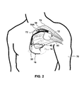
- FIG. 2 is a schematic illustration of an implantation of an exemplary implantable medical device and an exemplary electrode element proximate to skeletal muscle.
- FIG. 3 is a block diagram showing a system that can deliver one or more electrical stimuli to a tissue and determine a concentration of ions in extracellular fluid as a function of the response to the stimuli.
- FIGS. 4A and 4B are timing diagrams illustrating stimuli and the responses of skeletal muscle thereto, according to various embodiments of the invention.
- FIG. 5 is a flow diagram illustrating a technique for calibrating a medical device to determine a concentration of ions in extracellular fluid.
- FIG. 6 is a flow diagram illustrating a technique for monitoring ion concentrations in extracellular fluid.
- FIG. 7 is a schematic diagram of an experimental setup to test muscle contractions due to electrical stimuli.
- FIG. 8 is a graph of exemplary data showing muscle force in various solutions of potassium versus time.
- FIG. 9 is a graph of exemplary data showing contraction amplitude versus potassium concentration.
- FIG. 1A is a schematic illustration of an exemplary embodiment of a system 10 that includes an implantable medical device (IMD) 12 in relationship to a heart 14 of a patient.
- IMD 12 is configured to be implanted in a human or animal body.
- IMD 12 comprises a multi-chamber pacemaker having cardioversion and defibrillation capabilities.
- the invention is not limited to the particular IMD shown.
- the invention need not be implemented as an implantable medical device.
- Each of the electrodes is coupled to one of the coiled conductors within the lead body.
- a connector 26 At the proximal end of right ventricular lead 16 is a connector 26 , which couples the coiled conductors in the lead body to IMD 12 via a connector module 28 .
- a coronary sinus lead 42 includes an elongated insulative lead body deployed in the great cardiac vein 44 .
- the lead body carries one or more coiled conductors coupled to one or more pace/sense electrodes 46 .
- Electrodes 46 are configured to deliver ventricular pacing to left ventricle 48 and are further configured to sense depolarizations of left ventricle 48 .
- Additional pace/sense electrodes may be deployed on coronary sinus lead 42 that are configured to pace and sense depolarizations of the left atrium 50 .
- connector 52 At the proximal end of coronary sinus lead 42 is connector 52 , which couples the coiled conductors in coronary sinus lead 42 to connector module 28 .
- An exemplary electrode element 54 A is coupled to the distal end of a lead 56 .
- Lead 56 carries one or more conductors separated from one another by insulative sheaths.
- a connector 58 at the proximal end of the lead couples the conductors in lead 56 to IMD 12 via connector module 28 .
- IMD 12 comprises a housing 60 formed from one or more materials, including conductive materials such as stainless steel or titanium.
- Housing 60 may include insulation, such as a coating of parylene or silicone rubber, and in some variations, all or a portion of housing 60 may be left uninsulated. The uninsulated portion of housing 60 can serve as a subcutaneous electrode and a return current path for electrical stimulations applied via other electrodes.
- electrode element 54 A includes two electrodes 62 A and 62 B. At least one of electrodes 62 A and 62 B is deployed in or near test tissue and delivers stimulation to the tissue, while the other provides a return current path.
- electrodes 62 A and 62 B are button electrodes, but the invention encompasses other electrode types as well.
- the invention will be described in terms of stimulation of muscle cells, but the invention can encompass other test tissues as well.
- the test tissue can comprise a collection of autologous or non-autologous cells that are sensitive to the concentration of the selected ion.
- the test tissue may be one of cardiac muscle, skeletal muscle, smooth muscle, nerve tissue, skin, or the like.
- the ions may be one of K + , Na + , Cl ⁇ , Ca 2+ , Mg 2+ , or HCO 3 ⁇ .
- possible ions may include drugs (such as Digitalis) that become ions in the blood or ECF, small molecules, endogenously charged molecules, or other molecules in their ionic forms. Concentrations of ions will be depicted with brackets such as [K + ], as in the example of the concentration of potassium ions. While [K + ] is discussed in detail as an exemplary ion concentration herein, any other ion concentrations may be additionally or alternatively detected according to the invention.
- IMD 12 includes one or more implantable pulse generators (IPGs) (not shown in FIG. 1A ) configured to generate stimuli to be delivered to one or more muscles of the patient via electrode element 54 A.
- IPGs implantable pulse generators
- skeletal muscle is generally the most desirable tissue, because it is usually readily accessible and response of skeletal muscle can be readily related to ion concentration. Furthermore, it may be desirable to stimulate skeletal muscles that do not get much use and are less prone to fatigue.
- the invention encompasses embodiments in which stimulation and response of other kinds of tissue can be related to ion concentration, but muscle tissue, such as skeletal muscle tissue is the exemplary tissue described herein.
- the invention encompasses monitoring other ion concentrations instead of or in addition to [K + ].
- [Na + ] or [Cl ⁇ ] may be detected when monitoring skeletal muscle due to the large concentration gradient between the ICF and ECF.
- the invention encompasses monitoring the concentration of any ion in the ECF or ICF based on the electrical and/or mechanical response of any tissue to a stimulus.
- Housing 60 may include one or more sensors (not shown in FIG. 1A ) configured to detect at least one response of the stimulated muscle to the electrical stimulation or stimulations.
- the sensor may be deployed elsewhere, such as on the distal end of lead 56 .
- the sensor detects the electromechanical response of the stimulated muscle. Examples of sensors will be described below.
- the distance between electrodes 62 A and 62 B can be a function of the pulse magnitude generated by an IPG, a target stimulation magnitude, and the kind of electrodes employed.
- a target stimulation magnitude For example, to deliver a stimulus with a field strength of 10 volts per centimeter (V/cm) using IMD 12 which is capable of producing 2 V pulses, electrodes 62 A and 62 B can be separated by two millimeters.
- the invention is not limited to any particular physical dimensions or stimulation magnitudes, however.
- IMD 12 also includes one or more IPGs configured to generate pacing stimuli to be delivered to one or more chambers of heart 14 .
- the IPGs that stimulate heart 14 may be, but need not be, the same IPG that generates muscle stimulations.
- IMD 12 further includes one or more processors (not shown in FIG. 1A ) that regulate the delivery of pacing pulses.
- the processor in IMD 12 is configured to apply a variety of pacing modes, including therapies that may be beneficial for patients suffering from heart failure, such as cardiac potentiation therapy (CPT) or cardiac resynchronization therapy (CRT).
- CPT cardiac potentiation therapy
- CRT cardiac resynchronization therapy
- CPT generally involves electrically stimulating one or more heart chambers to induce post-extrasystolic potentiation
- CRT involves delivering pacing pulses to one or both ventricles to synchronize ventricular contractions.
- FIG. 1B is a schematic illustration of IMD 12 , with an alternate embodiment of an electrode element 54 B.
- electrode element 54 B like electrode element 54 A, is coupled to the distal end of lead 56 , which carries one or more conductors separated from one another by insulative sheaths and is coupled to connector module 28 via connector 58 .
- Electrode element 54 B includes two electrodes 62 C and 62 D, which deliver electrical stimulation to muscle, or other tissue sensitive to [K + ], and provide a return current path.
- electrodes 62 C and 62 D may deliver electrical stimulation to the same tissue or another tissue sensitive to a different ion concentration, such as [Na + ] or [Cl ⁇ ].
- Electrode element 54 B resembles a pace/sense electrode, such as pace/sense electrode 32 in FIG. 1A , in that electrode element 54 B includes a tip electrode 62 C and a ring electrode 62 D. Dimensions of electrode element 54 B may be comparable to those of conventional pace/sense electrodes. Although not shown in FIG. 1B , the distal end of lead 56 may include one or more fixation mechanisms configured to prevent or reduce lead migration.
- FIG. 1C is a schematic illustration of IMD 12 , with another alternate embodiment of an electrode element 54 C.
- electrode element 54 C includes an electrode 62 E deployed at the distal end of lead 56 , and another electrode 62 F in the body of housing 60 .
- Housing electrode 62 F can be deployed at any site in housing 60 .
- Lead electrode 62 E is configured to generate an intense electrical field at the site of stimulation.
- a point at the distal end of lead electrode 62 E causes the electric field to be more intense at the point, which can improve the likelihood of stimulation of muscle tissue or other tissue sensitive to the concentration of an ion of interest, such as [K + ].
- the distal end of lead 56 may include one or more fixation mechanisms configured to prevent or reduce lead migration.
- FIG. 1D is a schematic illustration of IMD 12 , with an additional alternate embodiment of an electrode element 54 D.
- Electrode element 54 D includes an electrode 62 G deployed on a fixed mount 64 .
- fixed mount 64 is coupled to connector module 28 , but fixed mount 64 may also be deployed elsewhere on IMD 12 .
- Exemplary electrode 62 G like electrode 62 E in FIG. 1C , is configured to generate an intense electrical field at the site of stimulation.
- Another electrode 62 H is deployed in the body of housing 60 .
- IMD 12 may place IMD 12 in direct contact with muscle such as skeletal muscle.
- the embodiment depicted in FIG. 1D may be desirable in such implantations, as electrodes 62 G and 62 H can be deployed without leads.
- FIG. 1E is a schematic illustration of IMD 12 , with a further alternate embodiment of an electrode element 54 E.
- Electrode element 54 E includes two electrodes 62 I and 62 J deployed in housing 60 .
- housing 60 may include an array of three or more electrodes.
- the embodiment shown in FIG. 1E may be desirable in implantations in which IMD 12 is implanted in direct contact with muscle or other ion concentration sensitive tissue.
- FIG. 1F is a schematic illustration of a further embodiment of the invention, in which one or more elements are external and are not configured to be implantable in a human or animal body.
- external medical device 65 includes one or more IPGs (not shown in FIG. 1F ) configured to generate stimuli to be delivered to one or more muscles of the patient via electrode element 66 .
- IPGs Transcutaneous Electrical Nerve Stimulation
- EMS Electronic Muscle Stimulation
- electro-acupuncture unit an electro-acupuncture unit.
- Medical device 65 or electrode element 66 may also include one or more sensors (not shown in FIG. 1F ) configured to detect an electromechanical response of the stimulated muscle to the electrical stimulation or stimulations.
- a sensor module distinct from device 65 or electrode element 66 may be deployed on the patient's skin to detect the electromechanical response.
- Electrode element 66 is coupled to medical device 65 via lead 67 .
- Electrode element 66 includes two electrodes 68 A and 68 B, which deliver electrical stimulation to muscle, or other tissue sensitive to [K + ] or another ion concentration, and provide a return current path.
- electrodes 68 A and 68 B are deployed externally with adhesive pads 69 A and 69 B, which adhere to the skin. Electrodes 68 A and 68 B may deliver an electrical stimulation to any of several tissues, especially skeletal muscles located beneath the skin.
- FIG. 1F is completely external with no implantable elements, the invention encompasses embodiments that have external and implantable elements.
- the invention is not limited to stimulation of skeletal muscle tissue, or stimulation via leads or electrodes that are separate from the leads or electrodes used to deliver therapeutic stimulation.
- ion imbalance may be determined directly in the organ of interest without the use of an additional stimulation pulse or stimulation lead.
- ion imbalance may be monitored by detecting the response of cardiac muscle to the therapeutic pacing stimuli delivered to heart 14 .
- CPT may be used to determine an ion concentration.
- CPT therapy provides an additional stimulus near the time of the T wave of the cardiac electrical signal to create a stronger ventricular contraction of heart 14 .
- the response to the stimulus may be sensitive to [Ca 2+ ], but other ion concentrations may be determined as well.
- FIG. 2 is a schematic illustration of an exemplary implantation in a patient 70 of the apparatus depicted in FIG. 1A .
- Right ventricular lead 16 , right atrial lead 30 and coronary sinus lead 42 are deployed in heart 14 via access through a vein such as the subclavian vein (not shown).
- Electrode element 54 A and lead 56 do not enter the cardiovascular system.
- electrode element 54 A is deployed proximate to skeletal muscle.
- electrode element 54 A is deployed proximate to the sternal portion 72 and clavicular portion 74 of the Pectoralis major.
- the invention also supports implantations in which electrode element 54 A is deployed proximate to other skeletal muscles, other muscles, or other tissues sensitive to [K + ], [Na + ], [Cl ⁇ ], [Ca 2+ ], [Mg 2+ ], [HCO 3 ⁇ ], or other ions in the ECF.
- Electrode element 54 A may include a fixation mechanism such as a loop or Dacron mesh that allows the surgeon to anchor electrode element 54 A in place with suture.
- housing 60 of IMD 12 is deployed in contact with pectoral muscles 72 and 74 .
- a conventional implantation technique for some implantable devices, such as a pacemaker, provides for deploying IMD 12 in direct contact with pectoral muscle. In such implantations, embodiments such as those depicted in FIGS. 1D and 1E may be feasible.
- FIG. 3 is a block diagram illustrating components of an exemplary system 10 such as the system depicted in FIG. 1A .
- Electrode element 54 A includes electrodes 62 A and 62 B, which are configured to deliver one or more electrical stimulations to a muscle or other tissue sensitive to [K + ] or another ion concentration.
- one of electrodes 62 A and 62 B introduces a stimulation from IMD 12 to a skeletal muscle, and the other of electrodes 62 A and 62 B provides the return current path.
- IMD 12 includes a sensor 80 that detects the electromechanical response of the muscle to the stimulations delivered by electrodes 62 A and 62 B.
- Sensor 80 can detect the mechanical response, the electrical response, or both. Examples of mechanical responses are muscle tension, muscle strength, muscle density, muscle length and pressure generated by the muscle.
- Sensor 80 can be deployed inside housing 60 of IMD 12 or outside housing 60 . Sensors such as an optical sensor could be configured to respond to one or more of these mechanical responses.
- An accelerometer which responds to muscle movement, is another example of a sensor that can detect a mechanical response.
- an accelerometer may be provided inside housing 60 to detect patient activity or posture. Such an accelerometer could also detect a mechanical response of stimulated muscle.
- an accelerometer may be disposed in device 65 , in electrode element 66 , or as a separate module deployed on the patient's skin.
- sensors that can detect a mechanical response are a pressure sensor and a piezoelectric sensor.
- Sensor 80 can also be configured to detect an electrical response.
- electrodes 62 A and 62 B not only deliver electrical stimulations to the muscle, but also convey the electrical response to sensor 80 .
- An example of a sensor that detects an electrical response is an impedance sensor.
- a pulse generator 82 in IMD 12 generates the stimulations that are delivered to the skeletal muscle via electrodes 62 A and 62 B.
- Pulse generator 82 may be, but need not be, the same component that generates pacing stimulations that are delivered to heart 14 .
- Pulse generator 82 operates under the control of processor 84 .
- Processor 84 can be embodied in one or more forms, such as a microprocessor, digital signal processor, application specific integrated circuit or full custom integrated circuit.
- processor 84 receives and analyzes signals detected via sensor 80 that are indicative of the response of the muscle to the stimulations, and determines a concentration of potassium or other ions in extracellular fluid (ECF) of the patient as a function of the signals.
- ECF extracellular fluid
- processor 84 can detect an ion imbalance in the patient.
- [K + ] in the ECF affects the response of the muscle or tissue being monitored.
- processor 84 may determine a concentration of another ion, such as [Na + ], [Cl ⁇ ], [Ca 2+ ], [Mg 2+ ], [HCO 3 ⁇ ], a drug, small molecule, or endogenously charged molecule.
- sensor 80 may be calibrated differently to account for the detection of the selected ion concentration.
- determining a concentration of one or more ions in ECF of the patient can include determining an absolute concentration, such as measuring or estimating the molarity of ions. Determining a concentration of potassium ions can also include determining a relative concentration, such as a concentration with respect to a baseline. Furthermore, determining a concentration of potassium ions can include determining a change in concentration over time. In practice, monitoring a change in concentration over time has clear clinical advantages.
- Processor 84 controls the scheduling of stimulations.
- Processor 84 may be configured to deliver the stimulations and monitor one or more ion concentrations when the patient is in bed, for example.
- Processor 84 may also be configured to deliver the stimulations and monitor the ion concentration a predetermined number of times each day.
- Processor 84 may further be configured to determine whether conditions are suitable for delivering stimulations and monitoring the ion concentration. For example, it may be desirable to monitor [K + ] or other ion concentrations once a day when the patient is inactive, particularly when the patient's muscles or other tissues are relaxed and when there is less likelihood of extraneous motion that could affect sensor 80 . When the patient is physically active, the physical activity can interfere with the monitoring of ion concentrations, such as [K + ]. Processor 84 may receive a signal from sensor 80 or from another sensor that generates a signal as a function of patient activity, such as an accelerometer. On the basis of the signal, processor 84 may determine whether the patient is too active or whether conditions are otherwise unsuitable for monitoring. When processor 84 determines that conditions are unsuitable, processor 84 may defer delivering stimulations and may reschedule the stimulations for a later time.
- processor 84 may be programmed to deliver the stimulations and monitor ion concentration in response to an event.
- IMD 12 When IMD 12 is a pacemaker or other device configured to treat arrhythmia, IMD 12 may apply therapy to treat the arrhythmia, then deliver the stimulations and monitor [K + ], to determine whether potassium ion concentration might be contributing to the arrhythmia.
- Processor 84 can further be configured to control delivery of pacing therapy to heart 14 .
- Another exemplary triggering event is the detection of a low level of physical activity indicative of the onset of rest or sleep.
- processor 84 may be programmed to deliver the stimulations and monitor one or more ion concentrations, such as [K + ], to predict an arrhythmia based upon an ion imbalance.
- IMD 12 may detect poor regulation of [K + ] and allow a physician to modify patient medication or suggest alternative diets.
- Exemplary medications may include anti-arrhythmic drugs, potassium channel inhibitors, or diets that include potassium sources such as bananas.
- IMD 12 may notify the patient of an ion imbalance with an audible sound or stimulation so that the patient may take precautions before the arrhythmia.
- IMD 12 includes a memory element 86 configured to store information about ion concentrations.
- Memory element 86 can store information such as the time when electrical stimulations were administered, the frequency of the stimulations, the muscle's response to the stimulations, and the determined ion concentration.
- Memory element 86 can also store a history of such monitoring, and can store information concerning the change in ion concentration over time.
- IMD 12 may detect more than one ion concentration at one time in the form of individual concentrations or concentration ratios. This multiple ion imbalance detection may be performed with multiple sensors 80 or derived from the tissue response.
- memory element 86 may store instructions for processor 84 to perform the multiple ion imbalance detection and store any data generated by the detection.
- memory element 86 may store instructions that cause a programmable processor, such as processor 84 , to carry out techniques for monitoring potassium ion concentration.
- Memory element 86 may include but is not limited to read-only memory, random access memory, Flash memory, EPROM and a magnetic or optical storage medium, or any combination thereof.
- processor 84 may take action. As an example, if the processor determines that [K + ] in ECF is elevated to the point that heart function may be adversely affected, or when processor 84 determines that [K + ] in ECF is rising to a point of concern, the processor may take action.
- Processor 84 may, for example, send a notification via an input/output element 88 .
- Input/output element 88 comprises one or more elements that relay the message to the patient, the patient's physician, or any other person or monitoring device.
- Input/output element 88 can include, for example, a radio frequency (RF) transmitter, an inductive coil transmitter or an audible alarm.
- RF radio frequency
- input/output element 88 may issue a warning to patient 12 if the determination of an ion concentration is above or below a predetermined threshold.
- input/output element 88 may transmit data stored by memory element 86 , i.e. ion concentration information or system 10 status data, to another computing device such as a notebook computer, hand held computer, physician programmer, personal computer, or network server.
- the data may be transmitted for analysis and/or storage.
- the data may be further forwarded to a hospital, clinic, manufacturer of IMD 12 , or another location where the data may be analyzed or stored.
- processor 84 can also control the delivery of therapy via a therapy element 90 .
- Therapy element 90 can include, for example, an implantable drug delivery device that delivers a drug to the patient.
- the drug may be a diuretic, for example.
- Therapy element 90 can work in concert with input/output element 88 .
- therapy element 90 can administer a drug while input/output element 88 can notify the patient that the patient should take an action, such as contacting his physician or controlling the potassium in his diet.
- Therapy element 90 can also encompass elements that pace heart 14 via leads 16 , 30 and 42 , or any combination thereof, as depicted in FIGS. 1A and 2 .
- pacing therapies would probably not be applied to address or control [K + ] or other ion concentrations.
- pacing therapies such as cardiac resynchronization and bi-ventricular pacing may be of benefit to patients having heart failure, such pacing therapies would not ordinarily be administered in response to elevated [K + ].
- Some pacing therapies can cause [K + ] to become even more elevated. Accordingly, although it is unlikely that processor 84 would apply pacing therapies to address elevated [K + ], processor 84 may monitor [K + ] to determine whether such pacing therapies ought to be employed or discontinued. In other words, processor 84 may monitor [K + ] or other ion concentrations to determine whether pacing therapies are likely to be safe and effective.
- FIGS. 4A and 4B are timing diagrams that illustrates exemplary techniques by which processor 84 can determine a concentration of potassium ion, as an example ion, in ECF as a function of the response of skeletal muscle, as an example tissue, to stimulations from an electrode element such as electrode elements 54 A-E.
- Each stimulus may have an amplitude of about two to twenty volts, for example, and a pulse width of about 0.1 to 1.0 milliseconds.
- Stimulus line 100 shows the timing of stimuli generated by pulse generator 82 delivered to the skeletal muscle via electrodes such as electrodes 62 A- 62 J.
- Response line 104 depicts a response of skeletal muscle to the stimulations in an environment where [K + ] is low relative to concentrations in ICF.
- response line 104 depicts a response of skeletal muscle in a “normal” patient.
- response line 104 depicts a response of skeletal muscle in a patient having elevated [K + ].
- a patient having elevated [K + ] is not normal and is at risk of heart failure.
- the response is depicted as muscle tension.
- Other responses such as muscle motion or muscle length, may also be evaluated, although the response waveforms may look different from those in FIGS. 4A and 4B .
- the response waveforms may look different from those in FIGS. 4A and 4B depending upon the muscle or other tissue being stimulated.
- the response waveform may include one or more action potentials
- Stimuli can be delivered in a range of frequencies, such as from about 10 Hz to about 150 Hz.
- a first set of stimuli 106 at a low frequency produces similar but distinct responses in normal [K + ] and elevated [K + ] environments.
- Contractions 108 in a normal muscle and contractions 110 in a muscle in an environment of elevated [K + ] are indicated by muscle tension as a function of time. In comparison to one another, contractions 108 in a normal muscle have a longer duration and may also exhibit some summation. In the example of FIG. 4A , contractions 108 also exhibit a greater amplitude. In contrast, contractions 110 in an elevated [K + ] environment are of a smaller amplitude, a shorter duration and exhibit little or no summation.
- a second set of stimuli 112 at a higher frequency produces distinct responses in normal [K + ] and elevated [K + ] environments as well.
- Contractions 114 in a normal muscle exhibit marked summation. The muscle approaches tetanus, but, as depicted in FIG. 4 , the frequency of stimulation is too low to produce a sustained tetanic response. Instead, muscle contractions 114 exhibit “ripples” or wavering, rather than the sustained contraction of tetanus. In contrast with contractions 114 , contractions 116 in an elevated [K + ] exhibit little or no summation.
- a third set of stimuli 118 at an even higher frequency produces contractions 120 in a normal muscle that show a tetanic response.
- muscle tension rises steadily to a maximum and levels off.
- Contractions 122 in an elevated [K + ] environment by contrast, exhibit summation, but the rise in tension is rippled and tension is not sustained.
- stimuli 118 produce a sustained response 120 in a normal [K + ] environment, but produce a rippled response 122 in an elevated [K + ] environment.
- the frequency of third set of stimuli 118 can be used to distinguish a normal [K + ] environment from an elevated [K + ] environment.
- the distinction can be achieved in a number of ways. For example, an analog or digital highpass filter may be employed to detect whether a ripple is present. Fourier or wavelet analysis may be used to detect the presence of high frequency components. Template matching or other morphological analysis may be performed. Other forms of analog or digital signal analysis may be used to detect the presence of a rippled response.
- a fourth set of stimuli 124 at an even higher frequency produces contractions 126 in a normal muscle and contractions 128 in an elevated [K + ] environment that are similar, in that both exhibit a tetanic response. Consequently, stimuli at this frequency would be less desirable for distinguishing a normal [K + ] environment from an elevated [K + ] environment.
- FIG. 4B shows additional distinction techniques.
- a set of stimuli 130 evokes responses 132 , 134 similar to responses 120 , 122 in FIG. 4A .
- the quantity of interest is the decline of the response following cessation of stimulation, which indicates how fast the stimulated muscle relaxes.
- the decline is indicated by angles ⁇ and ⁇ of lines tangent to the responses.
- the response returns to resting more quickly in an elevated [K + ] environment and more slowly in a normal [K + ] environment, so angle ⁇ is generally larger and indicative of a greater slope than angle cc.
- Another measurement of the decline of the response is the fall time, i.e., the time for the response to decrease from one value to another.
- Fall time can be determined by measuring the time it takes for the response to fall from its peak value to half its peak value, for example, or the time it takes for the response to fall from ninety percent of its peak value to ten percent of its peak value.
- the signal decays more quickly in elevated [K + ] environment and more slowly in a normal [K + ] environment, so the fall time in the elevated [K + ] environment is smaller than the fall time in a normal [K + ] environment.
- Processor 84 may detect the rate of muscle relaxation with any analog or digital technique, such as taking a difference at discrete points, measuring the time between high and low values, or differentiating the response waveform.
- processor 84 may detect the pulse width or action potential duration of the response. Because the response returns to resting more quickly in an elevated [K + ] environment than in a normal [K + ] environment, the pulse width of the in an elevated [K + ] environment is narrower than in a normal [K + ] environment. The narrower pulse width is associated with the shorter refractory period in an elevated [K + ] environment. Narrower pulse width in an elevated [K + ] environment has been demonstrated with both cardiac muscle and skeletal muscle.
- a set of stimuli 142 illustrates another distinction technique. This process includes delivering pairs of stimuli separated by different time intervals. In FIG. 4B , the initial pair of stimuli is separated by a very short interval, and subsequent pairs are separated by larger intervals. In an elevated [K + ] environment, the response will exhibit a two-peak ripple at a smaller interval than in a normal [K + ] environment. Processor 84 can detect the presence of the two-peak ripple using any signal processing technique, including techniques mentioned above.
- Another distinction technique is to “sweep” through a range of frequencies, as illustrated by set of stimuli 148 .
- the response 150 exhibits more rapid summation and reaches a sustained response in a shorter time.
- the response 152 in an elevated [K + ] environment is slower to exhibit summation and sustained response.
- Processor 84 can detect the onset of rapid summation and sustained response any signal processing technique, including techniques mentioned above.
- sensor 80 could respond to muscle motion or muscle length, for example.
- other signals may be measured in other tissue, which may be sensitive to [K + ] or other ion concentrations.
- action potentials may be measured in nerve tissues.
- FIG. 4A shows, it may be more difficult to distinguish whether [K + ] is low or elevated when stimulations are applied at high frequencies. Further, the frequency at which a normal [K + ] environment can be distinguished from an elevated [K + ] environment may vary from patient to patient. Accordingly, a patient who has received IMD 12 may undergo one or more tests to calibrate muscle response to [K + ] or other tissue response to [K + ].
- the detection of different ion concentrations may be performed in a similar manner.
- delivered stimuli may be different depending on the tissue being stimulated and the ion concentration being detected.
- FIG. 5 illustrates an exemplary calibration procedure.
- FIG. 5 illustrates an example embodiment related to monitoring muscle tissue and [K + ]
- the illustrated technique may be applicable to calibration for monitoring of other tissues, such as nerve tissue, which may be sensitive to [K + ] and/or other ion concentrations.
- IMD 12 delivers one or more electrical stimulations to the muscle of the patient via the electrodes ( 160 ).
- the stimulations may be delivered according to a particular parameter, such as a known frequency.
- a known frequency For purposes of illustration, it is assumed that the stimulation parameter is a known frequency of stimulation, and that the initial known frequency is a low frequency. It is further assumed that the characteristic of interest is whether the muscle exhibits a sustained tissue response.
- IMD 12 detects the response of the muscle to the stimulations ( 162 ) and performs signal analysis to determine whether stimulations at the known frequency produce a tissue response ( 164 ). If not, the frequency may be changed ( 166 ), e.g., increased, and the testing may be performed again ( 160 ). At some point, the patient will exhibit a rippled response, and at a higher frequency the patient will exhibit a sustained response.
- the patient has his ECF [K + ] measured by conventional laboratory techniques.
- Data concerning [K + ] are then correlated to data pertaining to the patient's response to stimulation at one or more frequencies.
- IMD 12 receives the data concerning measured [K + ], and processor 84 performs the correlation.
- another processor performs the correlation, and the relationship is supplied to processor 84 via input/output element 88 .
- IMD 12 stores the relationship between a known [K + ] and the patient's response ( 168 ). In this way, a baseline measurement of [K + ] can be established for the patient. Future determinations of [K + ] can be measured against the baseline. If, at later time, the patient exhibits a sustained response at lower frequency, then [K + ] has declined in comparison to the baseline. Conversely, if the later patient exhibits a sustained response at higher frequency, then [K + ] has increased with respect to the baseline.
- FIG. 5 illustrates calibration by observing sustained response
- calibration may also be performed using other responses.
- Other responses can include, for example, the rate of relaxation following cessation of stimulation, the pulse width of a response, the occurrence of summation in the response, the amplitude of a response, or any combination thereof.
- IMD 12 may deliver stimuli at different amplitudes. By iterative experimentation, IMD 12 can discover what amplitude of stimulation will produce a response. IMD 12 may be programmed to adjust the amplitude of stimulation as appropriate. Techniques to calibrate the IMD to detect other ions may be similar to the described technique to calibrate IMD 12 for [K + ].
- FIG. 6 is a flow diagram illustrating a technique for monitoring ECF potassium ion concentration and for delivering therapy in response to a determination of ECF potassium ion concentration.
- processor 84 determines that it is time for a scheduled monitoring or when processor 84 detects a triggering event that can activate monitoring, processor 84 initiates the monitoring process ( 170 ). Before actually conducting the monitoring, however, processor 84 determines whether the conditions are suitable for monitoring ( 172 ). An illustrative situation in which conditions might not be suitable for monitoring is a situation in which the patient has a high level of physical activity. When a signal from an activity sensor indicates that the patient is physically active, it may be difficult to monitor [K + ] accurately. When processor 84 determines that conditions are not suitable for monitoring, processor 84 can defer monitoring to a later time ( 174 ).
- IMD 12 delivers one or more electrical stimulations to the tissue of the patient ( 176 ).
- the stimulations may include a set of stimulations delivered at a known frequency or a set of stimulations that sweep through a range of frequencies.
- IMD 12 detects the response of the tissue to the stimulations ( 178 ).
- stimulations and detection may be repeated. For example, a later set of stimulations may be repeated at a known frequency that is different from an earlier set of stimulations.
- processor 84 determines a concentration of potassium ions in ECF of the patient ( 180 ). As noted above, this determination can include determining an absolute concentration, determining a relative concentration or determining a change in concentration, or any combination thereof.
- processor 84 determines whether action should be taken.
- the action in question is whether therapy is indicated ( 182 ).
- processor 84 controls therapy element 90 to deliver therapy to the patient ( 184 ).
- the invention is not limited to instances in which IMD 12 takes action in the form of administration of therapy. Other kinds of action include transmitting a notification via input/output element 88 or changing how often IMD 12 monitors [K + ].
- the results of the determination ( 180 ), and the delivery of therapy, if any, may be recorded in memory 86 ( 186 ).
- data stored in memory are useful for monitoring the change in [K + ] over time and for documenting the response of the patient to therapy.
- the techniques illustrated by FIG. 6 may additionally or alternative be used to monitor the concentration of ions other than potassium.
- FIG. 7 is a schematic diagram illustrating an experimental setup that was used to test muscle contractions due to electrical stimuli.
- mouse skeletal muscle 202 was held between clamps 208 and 210 in a chamber 190 .
- Clamp 210 was connected to a wall of chamber 190 by a support structure 206 while clamp 208 was connected to force transducer 212 .
- Force transducer 212 was connected to support structure 204 , which was attached to chamber 190 .
- Chamber 190 was contained within bath 188 .
- Electrical stimulator 192 provided electrical stimuli to muscle 202 through electrodes 198 and 200 .
- Electrodes 198 and 200 were coupled to electrical stimulator 192 by wires 194 and 196 , respectively.
- bath 188 was set to 37 degrees Celsius, and chamber 190 was filled with potassium buffer that was controlled to provide varying concentrations of potassium ions to determine how muscle 202 contracts with electrical stimuli in the presence of differing potassium ion concentrations.
- Muscle 202 was an isolated mouse skeletal muscle.
- Force transducer 212 was a strain gauge. Biphasic electrical stimuli was delivered to muscle 202 via electrodes 198 and 200 in order to trigger isometric contractions in the muscle.
- a computing device monitors the measurements from force transducer 212 in real-time or offline.
- the experimental setup described in FIG. 7 may be varied to determine contraction forces from other tissues or using other devices.
- FIG. 8 is a graph of experimental data showing muscle force in various solutions of potassium versus time.
- Graph 214 shows electrical stimuli 216 and 218 in conjunction with measured forces of muscle 202 of FIG. 7 .
- Broken line 220 represents contractions when [K + ] equals 2 millimoles (mM)
- solid line 222 represents contractions when [K + ] equals 4 mM
- dotted line 224 represents contractions when [K + ] equals 10 mM.
- Contraction force was highest when [K + ] equaled 2 mM, which is a lower [K + ] than the normal potassium ion concentrations for a mouse.
- a burst electrical stimulation consisting of 5 pulses with a frequency of 50 Hz were applied to muscle 202 .
- Pulses were biphasic with anodic and cathodic pulse durations of 1 millisecond (ms), and 18 ms of pause between each pulse.
- FIG. 9 is a graph of experimental data showing contraction amplitude versus potassium concentration.
- Graph 226 displays contraction amplitudes in Volts according to three different electrical stimuli frequencies. Volts may be translated into force measurements by a calibration procedure. Solid line 228 and included closed boxes are representative of 50 Hz stimulation, broken line 230 and included open boxes are representative of 100 Hz stimulation, and dotted line 232 and included closed circles are representative of 150 Hz stimulation.
- the [K + ] was varied in the sequence of 4 mM, 10 mM, 4 mM, 2 mM, and 4 mM.
- the results showed that the amplitude of the force generated by muscle 202 may be determined by the [K + ] when the stimulation frequency 50 Hz and 100 Hz.
- stimulation at 150 Hz may also be used to determine [K + ] in skeletal muscle, but was less sensitive to [K + ] than the other frequencies tested.
- Other frequencies not tested in the experiment of FIGS. 7-9 may also be useful for electrical stimulation.
- tissues may be tested and may respond similarly as the mouse skeletal muscle.
- Other frequencies and [K + ] may also be tested, while the exemplary conditions provided herein are only a small sample of [K + ] that may be detected with electrical stimulation.
- the invention may produce one of more advantages.
- the invention supports long-term implantation.
- Conventional ion sensors have proven to be unstable over extended periods. Some sensors require a periodic replacement of a sensing element, and other sensors lose sensitivity when the body naturally encapsulates the implanted elements. Some sensors also can be rejected by the body of the patient.
- IMDs such as those described above, however, have proven to be well tolerated in the long term. Rejection rates are low. Further, the IMD can respond to encapsulation by increasing the voltage of stimulations to provoke a response.
- the stimulations need not be painful. In practice, the patient may very likely experience a tingle. The tingle may be uncomfortable, but it would probably not be painful as long as stimulations are adjusted to a voltage that provokes a response and is not excessive. Further, as discussed above, the stimulations may be therapeutic stimulation of, for example, cardiac muscle or nervous tissue, that would have otherwise been delivered to the patient whether or not [K + ] was monitored. There may further be an element of convenience to the patient, as the patient may reduce the number of tests that rely upon blood samples.
- IMDs such as those described above can be implanted using conventional, well-established surgical techniques.
- an electrode configured to deliver an electrical stimulation to a tissue may be deployed as part of conventional device implantation technique, with little or no additional incision or trauma to the patient.
- Many patients experiencing heart failure may benefit from the implantation of an IMD that combines pacing therapies and potassium monitoring capability.
- the invention supports embodiments that include one or more external elements, which may offer further advantages.
- a patient may receive the embodiment depicted in FIG. 1F , for example, without surgery.
- An external electrode element such as that depicted in FIG. 1F , may be deployed at several sites on the body of the patient without surgery.
- An external electrode element may also be readily redeployed from one site to another.
- the invention has been depicted in the context of a pacemaker having one or more leads configured to deliver pacing stimuli to a heart, the invention can also be implemented in conjunction with other implantable and external devices.
- the invention can be implemented with a neurostimulator that includes a lead configured to deliver a pacing stimulation to a nerve, or a drug pump that includes a pump configured to deliver a drug to the patient from a reservoir.
- the invention may also be implemented as a standalone ion imbalance detector.
- the invention may be embodied in a transitory or non-transitory computer-readable medium with instructions that cause a programmable processor to carry out the techniques described above.
- a “computer-readable medium” includes but is not limited to read-only memory, Flash memory, EPROM and a magnetic or optical storage medium.
- a non-transitory computer readable medium includes all computer readable media except for a transitory, propagating signal.
- the medium may comprise instructions for causing a programmable processor to control a pulse generator to deliver an electrical stimulation to a muscle in a patient, for example, or receive from a sensor a signal indicative of a response of the tissue to the electrical stimulations.
- Example tissues include skeletal, cardiac or smooth muscle, as well and nerve or dermal tissues.
- Example ions include potassium, sodium, chloride, calcium, or magnesium ions, as well as drugs that become ions in the blood or ECF, small molecules, or endogenously charged molecules.
Abstract
Description
Claims (19)
Priority Applications (1)
| Application Number | Priority Date | Filing Date | Title |
|---|---|---|---|
| US14/514,829 US9289165B2 (en) | 2005-02-07 | 2014-10-15 | Ion imbalance detector |
Applications Claiming Priority (3)
| Application Number | Priority Date | Filing Date | Title |
|---|---|---|---|
| US65049705P | 2005-02-07 | 2005-02-07 | |
| US11/349,540 US8903492B2 (en) | 2005-02-07 | 2006-02-07 | Ion imbalance detector |
| US14/514,829 US9289165B2 (en) | 2005-02-07 | 2014-10-15 | Ion imbalance detector |
Related Parent Applications (1)
| Application Number | Title | Priority Date | Filing Date |
|---|---|---|---|
| US11/349,540 Division US8903492B2 (en) | 2005-02-07 | 2006-02-07 | Ion imbalance detector |
Publications (2)
| Publication Number | Publication Date |
|---|---|
| US20150032023A1 US20150032023A1 (en) | 2015-01-29 |
| US9289165B2 true US9289165B2 (en) | 2016-03-22 |
Family
ID=36263838
Family Applications (3)
| Application Number | Title | Priority Date | Filing Date |
|---|---|---|---|
| US11/349,058 Abandoned US20060217771A1 (en) | 2005-02-07 | 2006-02-07 | Potassium monitoring |
| US11/349,540 Active 2030-07-04 US8903492B2 (en) | 2005-02-07 | 2006-02-07 | Ion imbalance detector |
| US14/514,829 Active US9289165B2 (en) | 2005-02-07 | 2014-10-15 | Ion imbalance detector |
Family Applications Before (2)
| Application Number | Title | Priority Date | Filing Date |
|---|---|---|---|
| US11/349,058 Abandoned US20060217771A1 (en) | 2005-02-07 | 2006-02-07 | Potassium monitoring |
| US11/349,540 Active 2030-07-04 US8903492B2 (en) | 2005-02-07 | 2006-02-07 | Ion imbalance detector |
Country Status (3)
| Country | Link |
|---|---|
| US (3) | US20060217771A1 (en) |
| EP (1) | EP1850910A1 (en) |
| WO (1) | WO2006086490A1 (en) |
Cited By (3)
| Publication number | Priority date | Publication date | Assignee | Title |
|---|---|---|---|---|
| US10542961B2 (en) | 2015-06-15 | 2020-01-28 | The Research Foundation For The State University Of New York | System and method for infrasonic cardiac monitoring |
| EP3654347A1 (en) | 2018-11-16 | 2020-05-20 | Kaunas University of Technology | A system and method for personalized monitoring of life-threatening health conditions in patients with chronic kidney disease |
| US11553861B1 (en) | 2018-05-29 | 2023-01-17 | My Salt and Sugar, LLC | Apparatus to detect salt concentrations and glucose in bodily fluids |
Families Citing this family (61)
| Publication number | Priority date | Publication date | Assignee | Title |
|---|---|---|---|---|
| US20060217771A1 (en) | 2005-02-07 | 2006-09-28 | Medtronic, Inc. | Potassium monitoring |
| US7809441B2 (en) | 2006-05-17 | 2010-10-05 | Cardiac Pacemakers, Inc. | Implantable medical device with chemical sensor and related methods |
| US20080172107A1 (en) * | 2007-01-11 | 2008-07-17 | Mcginnis William J | Stand alone osteogenic stimulus device and method of using |
| US7734349B2 (en) * | 2007-07-18 | 2010-06-08 | Cardiac Pacemakers, Inc. | Osmometric heart monitoring device and methods |
| US8864677B2 (en) * | 2008-03-13 | 2014-10-21 | Cardiac Pacemakers, Inc. | Systems and methods for myocardial ischemia detection |
| US8200335B2 (en) * | 2008-10-31 | 2012-06-12 | Medtronic, Inc. | Implantable medical device lead connection assembly |
| US8290593B2 (en) * | 2008-10-31 | 2012-10-16 | Medtronic, Inc. | Implantable medical device including a plurality of lead connection assemblies |
| WO2010051492A1 (en) * | 2008-10-31 | 2010-05-06 | Medtronic, Inc. | Implantable medical device including a plurality of lead connection assemblies |
| US9399091B2 (en) | 2009-09-30 | 2016-07-26 | Medtronic, Inc. | System and method to regulate ultrafiltration |
| WO2012148784A2 (en) | 2011-04-29 | 2012-11-01 | Medtronic, Inc. | Method and device to monitor patients with kidney disease |
| US9848778B2 (en) | 2011-04-29 | 2017-12-26 | Medtronic, Inc. | Method and device to monitor patients with kidney disease |
| US9700661B2 (en) | 2011-04-29 | 2017-07-11 | Medtronic, Inc. | Chronic pH or electrolyte monitoring |
| US9456755B2 (en) | 2011-04-29 | 2016-10-04 | Medtronic, Inc. | Method and device to monitor patients with kidney disease |
| CN105288763B (en) | 2011-08-02 | 2018-01-02 | 美敦力公司 | Hemodialysis system with the flow path with controllable compliance volume |
| WO2013025844A2 (en) | 2011-08-16 | 2013-02-21 | Medtronic, Inc. | Modular hemodialysis system |
| EP2800592B1 (en) | 2012-01-04 | 2019-03-06 | Medtronic Inc. | Multi-staged filtration system for blood fluid removal |
| US10905816B2 (en) | 2012-12-10 | 2021-02-02 | Medtronic, Inc. | Sodium management system for hemodialysis |
| US9713666B2 (en) | 2013-01-09 | 2017-07-25 | Medtronic, Inc. | Recirculating dialysate fluid circuit for blood measurement |
| US11154648B2 (en) | 2013-01-09 | 2021-10-26 | Medtronic, Inc. | Fluid circuits for sorbent cartridge with sensors |
| US11565029B2 (en) | 2013-01-09 | 2023-01-31 | Medtronic, Inc. | Sorbent cartridge with electrodes |
| US9707328B2 (en) | 2013-01-09 | 2017-07-18 | Medtronic, Inc. | Sorbent cartridge to measure solute concentrations |
| US10850016B2 (en) | 2013-02-01 | 2020-12-01 | Medtronic, Inc. | Modular fluid therapy system having jumpered flow paths and systems and methods for cleaning and disinfection |
| US9623164B2 (en) | 2013-02-01 | 2017-04-18 | Medtronic, Inc. | Systems and methods for multifunctional volumetric fluid control |
| US9526822B2 (en) | 2013-02-01 | 2016-12-27 | Medtronic, Inc. | Sodium and buffer source cartridges for use in a modular controlled compliant flow path |
| US10543052B2 (en) | 2013-02-01 | 2020-01-28 | Medtronic, Inc. | Portable dialysis cabinet |
| US10010663B2 (en) | 2013-02-01 | 2018-07-03 | Medtronic, Inc. | Fluid circuit for delivery of renal replacement therapies |
| US9827361B2 (en) | 2013-02-02 | 2017-11-28 | Medtronic, Inc. | pH buffer measurement system for hemodialysis systems |
| US9144640B2 (en) | 2013-02-02 | 2015-09-29 | Medtronic, Inc. | Sorbent cartridge configurations for improved dialysate regeneration |
| US9138157B2 (en) | 2013-10-17 | 2015-09-22 | Medtronic, Inc. | Method and apparatus for cardiac function monitoring |
| US9131865B2 (en) | 2013-10-17 | 2015-09-15 | Medtronic, Inc. | Method and apparatus for cardiac function monitoring |
| US10076283B2 (en) | 2013-11-04 | 2018-09-18 | Medtronic, Inc. | Method and device to manage fluid volumes in the body |
| US9884145B2 (en) | 2013-11-26 | 2018-02-06 | Medtronic, Inc. | Parallel modules for in-line recharging of sorbents using alternate duty cycles |
| US10537875B2 (en) | 2013-11-26 | 2020-01-21 | Medtronic, Inc. | Precision recharging of sorbent materials using patient and session data |
| US10617349B2 (en) | 2013-11-27 | 2020-04-14 | Medtronic, Inc. | Precision dialysis monitoring and synchronization system |
| US9421382B2 (en) | 2013-12-13 | 2016-08-23 | Medtronic, Inc. | Method and apparatus for monitoring of patient medication compliance |
| EP3160534A4 (en) | 2014-06-24 | 2018-03-07 | Medtronic Inc. | Stacked sorbent assembly |
| EP3160535A4 (en) | 2014-06-24 | 2018-03-07 | Medtronic Inc. | Modular dialysate regeneration assembly |
| US10098993B2 (en) | 2014-12-10 | 2018-10-16 | Medtronic, Inc. | Sensing and storage system for fluid balance |
| US9895479B2 (en) | 2014-12-10 | 2018-02-20 | Medtronic, Inc. | Water management system for use in dialysis |
| US9713665B2 (en) | 2014-12-10 | 2017-07-25 | Medtronic, Inc. | Degassing system for dialysis |
| US10874787B2 (en) | 2014-12-10 | 2020-12-29 | Medtronic, Inc. | Degassing system for dialysis |
| US10716500B2 (en) | 2015-06-29 | 2020-07-21 | Cardiac Pacemakers, Inc. | Systems and methods for normalization of chemical sensor data based on fluid state changes |
| WO2017078965A1 (en) | 2015-11-06 | 2017-05-11 | Medtronic, Inc | Dialysis prescription optimization for decreased arrhythmias |
| US10874790B2 (en) | 2016-08-10 | 2020-12-29 | Medtronic, Inc. | Peritoneal dialysis intracycle osmotic agent adjustment |
| US10994064B2 (en) | 2016-08-10 | 2021-05-04 | Medtronic, Inc. | Peritoneal dialysate flow path sensing |
| US11013843B2 (en) | 2016-09-09 | 2021-05-25 | Medtronic, Inc. | Peritoneal dialysis fluid testing system |
| US10981148B2 (en) | 2016-11-29 | 2021-04-20 | Medtronic, Inc. | Zirconium oxide module conditioning |
| CN108968976B (en) | 2017-05-31 | 2022-09-13 | 心脏起搏器股份公司 | Implantable medical device with chemical sensor |
| US10960381B2 (en) | 2017-06-15 | 2021-03-30 | Medtronic, Inc. | Zirconium phosphate disinfection recharging and conditioning |
| CN109381195B (en) | 2017-08-10 | 2023-01-10 | 心脏起搏器股份公司 | Systems and methods including electrolyte sensor fusion |
| CN109419515B (en) | 2017-08-23 | 2023-03-24 | 心脏起搏器股份公司 | Implantable chemical sensor with staged activation |
| CN109864746B (en) | 2017-12-01 | 2023-09-29 | 心脏起搏器股份公司 | Multimode analyte sensor for medical devices |
| CN109864747B (en) | 2017-12-05 | 2023-08-25 | 心脏起搏器股份公司 | Multimode analyte sensor optoelectronic interface |
| US11278654B2 (en) | 2017-12-07 | 2022-03-22 | Medtronic, Inc. | Pneumatic manifold for a dialysis system |
| US11033667B2 (en) | 2018-02-02 | 2021-06-15 | Medtronic, Inc. | Sorbent manifold for a dialysis system |
| US11110215B2 (en) | 2018-02-23 | 2021-09-07 | Medtronic, Inc. | Degasser and vent manifolds for dialysis |
| US11213616B2 (en) | 2018-08-24 | 2022-01-04 | Medtronic, Inc. | Recharge solution for zirconium phosphate |
| US11806457B2 (en) | 2018-11-16 | 2023-11-07 | Mozarc Medical Us Llc | Peritoneal dialysis adequacy meaurements |
| US11806456B2 (en) | 2018-12-10 | 2023-11-07 | Mozarc Medical Us Llc | Precision peritoneal dialysis therapy based on dialysis adequacy measurements |
| US11850344B2 (en) | 2021-08-11 | 2023-12-26 | Mozarc Medical Us Llc | Gas bubble sensor |
| US11944733B2 (en) | 2021-11-18 | 2024-04-02 | Mozarc Medical Us Llc | Sodium and bicarbonate control |
Citations (176)
| Publication number | Priority date | Publication date | Assignee | Title |
|---|---|---|---|---|
| US3608729A (en) | 1967-09-27 | 1971-09-28 | Nat Res Dev | Disposable dialyser pack with adsorbent |
| US3669880A (en) | 1969-06-30 | 1972-06-13 | Cci Aerospace Corp | Recirculation dialysate system for use with an artificial kidney machine |
| US3669878A (en) | 1968-12-02 | 1972-06-13 | Health Education And Welfare U | Treatment of dialysate solution for removal of urea |
| US3850835A (en) | 1971-11-08 | 1974-11-26 | Cci Life Systems Inc | Method of making granular zirconium hydrous oxide ion exchangers, such as zirconium phosphate and hydrous zirconium oxide, particularly for column use |
| US3884808A (en) | 1973-06-20 | 1975-05-20 | Res Dev Systems Inc | Wearable, self-regenerating dialysis appliance |
| US3989622A (en) | 1970-12-30 | 1976-11-02 | Cci Life Systems, Inc. | Urease in insoluble form for converting urea present in a liquid |
| US4060485A (en) | 1975-06-09 | 1977-11-29 | I T L Technology, Inc. | Dialysis apparatus |
| US4371385A (en) | 1981-04-28 | 1983-02-01 | Cobe Laboratories, Inc. | Deaerating liquid |
| US4374382A (en) | 1981-01-16 | 1983-02-15 | Medtronic, Inc. | Marker channel telemetry system for a medical device |
| US4381999A (en) | 1981-04-28 | 1983-05-03 | Cobe Laboratories, Inc. | Automatic ultrafiltration control system |
| US4460555A (en) | 1983-08-25 | 1984-07-17 | Organon Teknika Corporation | Ammonia scavenger |
| US4556063A (en) | 1980-10-07 | 1985-12-03 | Medtronic, Inc. | Telemetry system for a medical device |
| US4562751A (en) | 1984-01-06 | 1986-01-07 | Nason Clyde K | Solenoid drive apparatus for an external infusion pump |
| US4581141A (en) | 1978-02-27 | 1986-04-08 | Purdue Research Foundation | Dialysis material and method for removing uremic substances |
| US4650587A (en) | 1982-09-09 | 1987-03-17 | Akzona Incorporated | Ammonia scavenger |
| US4678408A (en) | 1984-01-06 | 1987-07-07 | Pacesetter Infusion, Ltd. | Solenoid drive apparatus for an external infusion pump |
| US4685903A (en) | 1984-01-06 | 1987-08-11 | Pacesetter Infusion, Ltd. | External infusion pump apparatus |
| EP0266795A2 (en) | 1986-11-07 | 1988-05-11 | Asahi Kasei Kogyo Kabushiki Kaisha | Improved regenerated cellulose membrane and process for preparation thereof |
| US4750494A (en) * | 1981-05-12 | 1988-06-14 | Medtronic, Inc. | Automatic implantable fibrillation preventer |
| US4826663A (en) | 1985-05-15 | 1989-05-02 | Eniricerche S.P.A. | Zirconium phosphate and method for its preparation |
| US4828693A (en) | 1987-09-22 | 1989-05-09 | Baxter Travenol Laboratories, Inc. | Water pressure regulator for hemodialysis apparatus |
| US5080653A (en) | 1990-04-16 | 1992-01-14 | Pacesetter Infusion, Ltd. | Infusion pump with dual position syringe locator |
| US5092886A (en) | 1987-09-29 | 1992-03-03 | Dobos Hardy Matyas | Implantable artificial kidney |
| US5097122A (en) | 1990-04-16 | 1992-03-17 | Pacesetter Infusion, Ltd. | Medication infusion system having optical motion sensor to detect drive mechanism malfunction |
| US5127404A (en) | 1990-01-22 | 1992-07-07 | Medtronic, Inc. | Telemetry format for implanted medical device |
| US5284470A (en) | 1992-11-02 | 1994-02-08 | Beltz Alex D | Wearable, portable, light-weight artificial kidney |
| US5302288A (en) | 1993-03-19 | 1994-04-12 | Zimpro Environmental, Inc. | Treatment of highly colored wastewaters |
| US5305745A (en) | 1988-06-13 | 1994-04-26 | Fred Zacouto | Device for protection against blood-related disorders, notably thromboses, embolisms, vascular spasms, hemorrhages, hemopathies and the presence of abnormal elements in the blood |
| US5318750A (en) | 1992-02-14 | 1994-06-07 | Lascombes Jean Jacques | Device for the preparation of a solution for medical use |
| US5468388A (en) | 1993-07-01 | 1995-11-21 | Sartorius Ag | Filter module with degassing feature |
| US5683432A (en) | 1996-01-11 | 1997-11-04 | Medtronic, Inc. | Adaptive, performance-optimizing communication system for communicating with an implanted medical device |
| US5762782A (en) | 1995-02-13 | 1998-06-09 | Aksys, Ltd. | Water treatment for dialysate preparation |
| WO1999037342A1 (en) | 1998-01-21 | 1999-07-29 | Gambro Ab | Safety arrangement for a dialysis machine and method of activating the safety arrangement |
| US5944684A (en) | 1995-08-31 | 1999-08-31 | The Regents Of The University Of California | Wearable peritoneum-based system for continuous renal function replacement and other biomedical applications |
| US6048732A (en) | 1996-10-16 | 2000-04-11 | Board Of Regents, The University Of Texas System | Receptor and method for citrate determination |
| US6052622A (en) | 1998-02-12 | 2000-04-18 | Pacesetter Ab | Heart stimulator with an evoked response detector |
| US6058331A (en) | 1998-04-27 | 2000-05-02 | Medtronic, Inc. | Apparatus and method for treating peripheral vascular disease and organ ischemia by electrical stimulation with closed loop feedback control |
| WO2000057935A1 (en) | 1999-03-30 | 2000-10-05 | Gambro Lundia Ab | Method, apparatus and components of dialysis system |
| WO2000066197A1 (en) | 1999-04-30 | 2000-11-09 | Children's Hospital Medical Center | Hemofiltration system |
| US6230059B1 (en) | 1999-03-17 | 2001-05-08 | Medtronic, Inc. | Implantable monitor |
| US6248093B1 (en) | 1998-10-29 | 2001-06-19 | Minimed Inc. | Compact pump drive system |
| US6254567B1 (en) | 1999-02-26 | 2001-07-03 | Nxstage Medical, Inc. | Flow-through peritoneal dialysis systems and methods with on-line dialysis solution regeneration |
| WO2001070307A1 (en) | 2000-03-23 | 2001-09-27 | Minimed, Inc. | Exchangeable electronic cards for infusion devices |
| WO2001085295A2 (en) | 2000-05-05 | 2001-11-15 | Hemocleanse, Inc. | Use of magnetic particles or other particles having relatively high density in a fluid for mixing and/or leak detection |
| US6321101B1 (en) | 1997-10-29 | 2001-11-20 | Pacesetter Ab | Method and device for determination of concentration |
| US6363279B1 (en) | 1996-01-08 | 2002-03-26 | Impulse Dynamics N.V. | Electrical muscle controller |
| US6362591B1 (en) | 1998-10-29 | 2002-03-26 | Minimed Inc. | Method and apparatus for detection of occlusions |
| US20020042561A1 (en) | 1997-10-20 | 2002-04-11 | Schulman Joseph H. | Implantable sensor and integrity tests therefor |
| US20020112609A1 (en) | 2000-11-28 | 2002-08-22 | Wong Raymond J. | Cartridges useful in cleaning dialysis solutions |
| US6554798B1 (en) | 1998-08-18 | 2003-04-29 | Medtronic Minimed, Inc. | External infusion device with remote programming, bolus estimator and/or vibration alarm capabilities |
| US20030080059A1 (en) | 1998-04-23 | 2003-05-01 | Peterson Michael J. | Apparatus for fluid delivery in a dialysis clinic |
| US20030097086A1 (en) | 2001-11-16 | 2003-05-22 | Victor Gura | Wearable continuous renal replacement therapy device |
| WO2003043680A1 (en) | 2001-11-23 | 2003-05-30 | Gambro Lundia Ab | Method of operating a dialysis machine |
| US20030105435A1 (en) | 1999-03-26 | 2003-06-05 | Taylor Michael A. | Water purification pack |
| US20030114787A1 (en) | 2001-12-13 | 2003-06-19 | Victor Gura | Wearable peritoneal dialysis system |
| US6589229B1 (en) | 2000-07-31 | 2003-07-08 | Becton, Dickinson And Company | Wearable, self-contained drug infusion device |
| US6602399B1 (en) | 2000-03-22 | 2003-08-05 | Max-Planck-Gesellschaft Zur Forderung Der Wissenchaften E.V. | Signal recording of a receptor-effector-system by an extracellular planar potential-sensitive electrode |
| US6627164B1 (en) | 2000-11-28 | 2003-09-30 | Renal Solutions, Inc. | Sodium zirconium carbonate and zirconium basic carbonate and methods of making the same |
| EP1364666A1 (en) | 2000-12-27 | 2003-11-26 | Philips Japan, Ltd | Biological information and blood treating device information control system, biological information and blood treating device information control device, and biological information and blood treating device information control method |
| US6676608B1 (en) | 2000-04-19 | 2004-01-13 | Cheetah Medical Ltd. | Method and apparatus for monitoring the cardiovascular condition, particularly the degree of arteriosclerosis in individuals |
| US20040019312A1 (en) | 2002-07-19 | 2004-01-29 | Childers Robert W. | Systems and methods for performing peritoneal dialysis |
| EP0906768B1 (en) | 1997-10-02 | 2004-02-25 | St. Jude Medical AB | Evoked response detector and a heart stimulator with such a detector |
| US6711439B1 (en) | 2002-02-14 | 2004-03-23 | Pacesetter, Inc. | Evoked response variability as an indicator of autonomic tone and surrogate for patient condition |
| WO2004030717A2 (en) | 2002-09-30 | 2004-04-15 | Insulet Corporation | Dispenser components and methods for infusion device |
| WO2004030716A2 (en) | 2002-09-30 | 2004-04-15 | Insulet Corporation | Components and methods for patient infusion device |
| WO2004009156A3 (en) | 2002-07-19 | 2004-05-06 | Baxter Int | Systems and methods for peritoneal dialysis |
| WO2004008826A3 (en) | 2002-07-19 | 2004-05-13 | Baxter Int | Systems and methods for performing peritoneal dialysis |
| US20040099593A1 (en) | 2002-11-25 | 2004-05-27 | Potito De Paolis | Concurrent dialysate purification cartridge |
| US20040147900A1 (en) | 2003-01-23 | 2004-07-29 | Hans-Dietrich Polaschegg | Low hydraulic resistance cartridge |
| US20040215090A1 (en) | 2003-04-25 | 2004-10-28 | Jouni Erkkila | Estimation of cardiac death risk |
| US20050065760A1 (en) | 2003-09-23 | 2005-03-24 | Robert Murtfeldt | Method for advising patients concerning doses of insulin |
| US6878283B2 (en) | 2001-11-28 | 2005-04-12 | Renal Solutions, Inc. | Filter cartridge assemblies and methods for filtering fluids |
| US20050126998A1 (en) | 2003-10-28 | 2005-06-16 | Childers Robert W. | Priming, integrity and head height methods and apparatuses for medical fluid systems |
| US20050150832A1 (en) | 2003-12-24 | 2005-07-14 | Chemica Technologies, Inc. | Dialysate regeneration system for portable human dialysis |
| US20050234381A1 (en) | 2004-03-20 | 2005-10-20 | Guenter Niemetz | Method for allowing operator entries at a medical instrument |
| US20050236330A1 (en) | 2000-12-22 | 2005-10-27 | Fresenius Medical Care Deutschland Gmbh. | Method for determining concentration; a dialyser |
| US20050274658A1 (en) | 2004-06-09 | 2005-12-15 | Rosenbaum Benjamin P | Dialysis system |
| US20060025661A1 (en) | 2004-08-02 | 2006-02-02 | Sweeney Robert J | Device for monitoring fluid status |
| US7077819B1 (en) | 1998-12-24 | 2006-07-18 | Fresenius Medical Care Deutschland Gmbh | Method for determining the distribution volume of a blood component during an extracorporeal blood treatment and device for carrying out the method |
| US20060195064A1 (en) | 2005-02-28 | 2006-08-31 | Fresenius Medical Care Holdings, Inc. | Portable apparatus for peritoneal dialysis therapy |
| US20060217771A1 (en) | 2005-02-07 | 2006-09-28 | Medtronic, Inc. | Potassium monitoring |
| US20060226079A1 (en) | 2005-04-08 | 2006-10-12 | Nikkiso Co. Ltd. | Hemodialysis apparatus and method for hemodialysis |
| US20060264894A1 (en) | 2005-05-06 | 2006-11-23 | Medtronic Minimed, Inc. | Infusion device and method with disposable portion |
| US20070007208A1 (en) | 2003-01-07 | 2007-01-11 | Nxstage Medical, Inc. | Batch filtration system for preparation of sterile fluid for renal |
| US20070066928A1 (en) | 2005-09-22 | 2007-03-22 | Jean-Michel Lannoy | Automation and optimization of CRRT treatment using regional citrate anticoagulation |
| US20070138011A1 (en) | 2005-12-20 | 2007-06-21 | Bruker Biospin Gmbh | Combined titration and pH electrode for the preparation of liquid samples in particular for NMR spectroscopy |
| US20070179431A1 (en) | 2006-01-30 | 2007-08-02 | The Regents Of The University Of California | Peritoneal dialysis methods and apparatus |
| US20070175827A1 (en) | 2006-02-02 | 2007-08-02 | Cardiac Pacemakers, Inc. | Cardiac rhythm management device and sensor-suite for the optimal control of ultrafiltration and renal replacement therapies |
| US20070215545A1 (en) | 2006-03-17 | 2007-09-20 | Children's Hospital Medical Center | Extracorporeal renal replacement modeling system |
| US20070255250A1 (en) | 2006-04-28 | 2007-11-01 | Moberg Sheldon B | Remote monitoring for networked fluid infusion systems |
| US20080021337A1 (en) | 2006-07-24 | 2008-01-24 | Dan Li | Cardiac signal display and event detection using multiresolution z-score transform |
| US20080067132A1 (en) | 2006-09-15 | 2008-03-20 | Edward Allan Ross | Method for using photoplethysmography to optimize fluid removal during renal replacement therapy by hemodialysis or hemofiltration |
| US20080215247A1 (en) | 2004-07-23 | 2008-09-04 | Claudio Tonelli | Machine and Procedure For Extracorporeal Treatment of Blood |
| WO2009026603A1 (en) | 2007-08-31 | 2009-03-05 | Zentrum Für Biomedizinische Technologie Der Donau-Universität Krems | Method for detecting the ion concentrations of citrate anti-coagulated extracorporeal blood purification |
| US20090101577A1 (en) | 2007-09-28 | 2009-04-23 | Fulkerson Barry N | Methods and Systems for Controlling Ultrafiltration Using Central Venous Pressure Measurements |
| US20090127193A1 (en) | 2007-11-16 | 2009-05-21 | Palmer David Updyke | Dialysis Systems and Methods |
| US7566432B2 (en) | 2004-12-28 | 2009-07-28 | Renal Solutions, Inc. | Method of synthesizing zirconium phosphate particles |
| EP2100553A1 (en) | 2008-03-10 | 2009-09-16 | BIOTRONIK CRM Patent AG | Apparatus and method to assess the risk of R-on-T event |
| US20090275883A1 (en) | 2008-05-02 | 2009-11-05 | Baxter International Inc. | Smart patient transfer set for peritoneal dialysis |
| US20090275849A1 (en) | 2008-05-02 | 2009-11-05 | Donald-Bane Stewart | Methods for Detection of Cardiac Arrhythmias |
| US20090282980A1 (en) | 2008-01-18 | 2009-11-19 | Victor Gura | Carbon Dioxide Gas Removal From a Fluid Circuit of a Dialysis Device |
| WO2009157877A1 (en) | 2008-06-23 | 2009-12-30 | Temasek Polytechnic | A sorbent for a dialysis device |
| US20100004588A1 (en) | 2008-07-01 | 2010-01-07 | Baxter International Inc. | Nanoclay sorbents for dialysis |
| US7674231B2 (en) | 2005-08-22 | 2010-03-09 | Massachusetts Institute Of Technology | Wearable pulse wave velocity blood pressure sensor and methods of calibration thereof |
| WO2010028860A1 (en) | 2008-09-15 | 2010-03-18 | B. Braun Avitum Ag | Method and device to early predict the kt/v parameter in kidney substitution treatments |
| US20100078387A1 (en) | 2008-09-30 | 2010-04-01 | Fresenius Medical Care Holdings, Inc. | Acid Zirconium Phosphate and Alkaline Hydrous Zirconium Oxide Materials For Sorbent Dialysis |
| US20100078381A1 (en) | 2008-09-30 | 2010-04-01 | Fresenius Medical Care Holdings, Inc. | Covalently Immobilized Enzyme and Method To Make The Same |
| US20100084330A1 (en) | 2008-10-03 | 2010-04-08 | Fresenius Medical Care Holdings, Inc. | Zirconium Phosphate Particles Having Improved Adsorption Capacity and Method Of Synthesizing The Same |
| US20100094158A1 (en) | 2006-09-19 | 2010-04-15 | Kristian Solem | Estimation of propensity to symptomatic hypotension |
| US7704361B2 (en) | 2000-12-12 | 2010-04-27 | Jurag Separation A/S | Method and apparatus for isolation of ionic species from a liquid |
| US20100114012A1 (en) | 2008-11-03 | 2010-05-06 | Sandford Harold F | Portable Peritoneal Dialysis System |
| US20100137693A1 (en) | 2005-11-01 | 2010-06-03 | Fresenius Medical Care Holdings, Inc. | Methods and systems for patient care |
| US20100168546A1 (en) | 2005-03-10 | 2010-07-01 | Dexcom, Inc. | System and methods for processing analyte sensor data for sensor calibration |
| US7756572B1 (en) | 2005-01-25 | 2010-07-13 | Pacesetter, Inc. | System and method for efficiently distinguishing among cardiac ischemia, hypoglycemia and hyperglycemia using an implantable medical device and an external system |
| US7754852B2 (en) | 2007-07-20 | 2010-07-13 | Mayo Foundation For Medical Education And Research | Natriuretic polypeptides |
| US20100224492A1 (en) | 2009-03-06 | 2010-09-09 | Baxter International Inc. | Hemodialysis and peritoneal dialysis systems having electrodeionization capabilities |
| US7794141B2 (en) | 2006-04-14 | 2010-09-14 | Deka Products Limited Partnership | Thermal and coductivity sensing systems, devices and methods |
| US20100234795A1 (en) | 2006-08-16 | 2010-09-16 | Wallenaes Anders | System and method for regeneration of a fluid |
| US20100241045A1 (en) | 2003-12-16 | 2010-09-23 | Baxter International Inc. | Renal therapy blood cleansing system with balance chamber and bolus, rinseback or prime volume feature |
| US20110017665A1 (en) | 2007-11-16 | 2011-01-27 | Fresenius Medical Care Holdings, Inc. | Dialysis Systems and Methods |
| WO2011025705A1 (en) | 2009-08-27 | 2011-03-03 | Baxter International Inc. | Dialysis treatment devices for removing urea |
| US20110066043A1 (en) | 2009-09-14 | 2011-03-17 | Matt Banet | System for measuring vital signs during hemodialysis |
| US20110077574A1 (en) | 2009-09-30 | 2011-03-31 | Medtronic, Inc. | System and method to regulate ultrafiltration |
| US20110079558A1 (en) | 2009-10-01 | 2011-04-07 | Fresenius Medical Care Holdings, Inc. | Method of controlling diffusive sodium transport in dialysis |
| US20110087187A1 (en) | 2008-04-30 | 2011-04-14 | Gambro Lundia Ab | Hydrophobic deaeration membrane |
| US20110130666A1 (en) | 2009-11-30 | 2011-06-02 | Yanting Dong | Enhanced reporting of pathological episodes |
| US7967022B2 (en) | 2007-02-27 | 2011-06-28 | Deka Products Limited Partnership | Cassette system integrated apparatus |
| US7981082B2 (en) | 2007-08-21 | 2011-07-19 | Hospira, Inc. | System and method for reducing air bubbles in a fluid delivery line |
| US20110272337A1 (en) | 2010-05-04 | 2011-11-10 | C-Tech Biomedical, Inc. | Dual mode hemodialysis machine |
| US20120016228A1 (en) | 2003-09-16 | 2012-01-19 | Cardiomems | System, apparatus, and method for in-vivo assessment of relative position of an implant |
| US20120085707A1 (en) | 2010-10-12 | 2012-04-12 | Fresenius Medical Care Holdings, Inc. | Systems and methods for compensation of compliant behavior in regenerative dialysis systems |
| US20120115248A1 (en) | 2009-07-01 | 2012-05-10 | Ansyln Eric V | Methods of determining the presence and/or concentration of an analyte in a sample |
| US8183046B2 (en) | 2007-01-11 | 2012-05-22 | The Board Of Trustees Of The University Of Illinois | Temperature resistant pH buffers for use at low temperatures |
| US8246826B2 (en) | 2007-02-27 | 2012-08-21 | Deka Products Limited Partnership | Hemodialysis systems and methods |
| US20120220528A1 (en) | 2011-02-25 | 2012-08-30 | Medtronic, Inc. | Systems and methods for therapy of kidney disease and/or heart failure using chimeric natriuretic peptides |
| US20120258546A1 (en) | 2011-04-08 | 2012-10-11 | Life Technologies Corporation | Automated On-Instrument pH Adjustment |
| US20120277546A1 (en) | 2011-04-29 | 2012-11-01 | Medtronic, Inc. | Method and device to monitor patients with kidney disease |
| US20120273420A1 (en) | 2011-04-29 | 2012-11-01 | Martin Gerber | ELECTROLYTE AND pH MONITORING FOR FLUID REMOVAL PROCESSES |
| WO2012148781A1 (en) | 2011-04-29 | 2012-11-01 | Medtronic, Inc. | Multimodal dialysis system |
| US8313642B2 (en) | 2008-07-09 | 2012-11-20 | Baxter International Inc. | Dialysis system including wireless patient data and trending and alert generation |
| WO2012162515A2 (en) | 2011-05-24 | 2012-11-29 | Deka Products Limited Partnership | Hemodial ysis system |
| JP5099464B1 (en) | 2011-12-29 | 2012-12-19 | 富田製薬株式会社 | Bicarbonate ion concentration-variable dialysate preparation device and preparation method, bicarbonate ion concentration-variable dialysate, and bicarbonate ion concentration-variable dialyzing system |
| WO2012172398A1 (en) | 2011-03-21 | 2012-12-20 | Gambro Lundia Ab | An apparatus for extracorporeal blood treatment |
| US8366316B2 (en) | 2006-04-14 | 2013-02-05 | Deka Products Limited Partnership | Sensor apparatus systems, devices and methods |
| WO2013019994A2 (en) | 2011-08-02 | 2013-02-07 | Medtronic, Inc. | Hemodialysis system having a flow path with a controlled compliant volume |
| WO2013019179A1 (en) | 2011-07-29 | 2013-02-07 | Baxter International Inc. | Sodium management for dialysis systems |
| US20130037465A1 (en) | 2005-05-06 | 2013-02-14 | Keith James Heyes | Fluid processing apparatus |
| US8409441B2 (en) | 2007-02-27 | 2013-04-02 | Deka Products Limited Partnership | Blood treatment systems and methods |
| EP2576453A2 (en) | 2010-05-24 | 2013-04-10 | Baxter International Inc. | Systems and methods for removing hydrogen peroxide from water purification systems |
| EP2575827A2 (en) | 2009-06-05 | 2013-04-10 | Fresenius Medical Care Holdings, Inc. | Urea sorbent |
| WO2013025844A3 (en) | 2011-08-16 | 2013-05-02 | Medtronic, Inc. | Modular hemodialysis system |
| WO2013028809A3 (en) | 2011-08-22 | 2013-05-16 | Medtronic, Inc. | Dual flow sorbent cartridge |
| WO2013103607A1 (en) | 2012-01-04 | 2013-07-11 | Fresenius Medical Care Holdings, Inc. | Method and system of enhancing removal of toxic anions and organic solutes in sorbent dialysis |
| WO2013103906A1 (en) | 2012-01-04 | 2013-07-11 | Medtronic, Inc. | Multi-staged filtration system for blood fluid removal |
| US8499780B2 (en) | 2007-02-27 | 2013-08-06 | Deka Products Limited Partnership | Cassette system integrated apparatus |
| WO2013114063A1 (en) | 2012-02-02 | 2013-08-08 | Quanta Fluid Solutions Ltd. | Dialysis machine |
| WO2013121162A1 (en) | 2012-02-14 | 2013-08-22 | Quanta Fluid Solutions Ltd | Dialysis machine |
| US20130274642A1 (en) | 2011-04-29 | 2013-10-17 | Medtronic, Inc. | Multimodal dialysis system |
| US20130324915A1 (en) | 2002-05-24 | 2013-12-05 | Baxter Healthcare S.A. | Stepper motor driven peritoneal dialysis machine |
| US20130331774A1 (en) | 2012-06-08 | 2013-12-12 | Fresenius Medical Care Holdings, Inc. | Medical fluid cassettes and related systems and methods |
| US20130330208A1 (en) | 2012-06-11 | 2013-12-12 | Fresenius Medical Care Holdings, Inc. | Medical fluid cassettes and related systems and methods |
| US20140018728A1 (en) | 2010-12-20 | 2014-01-16 | Fresenius Medical Care Holdings, Inc. | Medical fluid cassettes and related systems and methods |
| US20140042092A1 (en) | 2010-04-16 | 2014-02-13 | Baxter Healthcare S.A. | Therapy prediction and optimization of serum potassium for renal failure blood therapy, especially home hemodialysis |
| EP2701580A2 (en) | 2011-04-29 | 2014-03-05 | Medtronic, Inc. | Method and device to monitor patients with kidney disease |
| US20140088442A1 (en) | 2011-04-29 | 2014-03-27 | Medtronic, Inc. | Method and device to monitor patients with kidney disease |
| US8696626B2 (en) | 2008-07-30 | 2014-04-15 | Claudia F. E. Kirsch | Debubbler |
| US20140110340A1 (en) | 2012-10-22 | 2014-04-24 | Baxter Healthcare S.A. | Total chlorine water detection system and method for medical fluid treatments |
| US20140110341A1 (en) | 2012-10-22 | 2014-04-24 | Baxter Healthcare S.A. | Integrated water testing system and method for ultra-low total chlorine detection |
| WO2014077082A1 (en) | 2012-11-15 | 2014-05-22 | ニプロ株式会社 | Dialysis unit and method for measuring access recirculation rate |
| US20140158538A1 (en) | 2012-12-10 | 2014-06-12 | Medtronic, Inc. | Potassium loaded ion-exchange material for use in a dialysate regeneration system |
| US20140158588A1 (en) | 2012-12-10 | 2014-06-12 | Medtronic, Inc. | pH AND BUFFER MANAGEMENT SYSTEM FOR HEMODIALYSIS SYSTEMS |
| US20140158623A1 (en) | 2012-12-10 | 2014-06-12 | Medtronic, Inc. | Sodium management for hemodialysis |
| US20140190876A1 (en) | 2013-01-09 | 2014-07-10 | Medtronic, Inc. | Sorbent cartridge to measure solute concentrations |
| WO2014121163A1 (en) | 2013-02-01 | 2014-08-07 | Mectronic, Inc. | Sodium and buffer source cartridges for use in a modular controlled complaint flow path |
| WO2014121169A1 (en) | 2013-02-02 | 2014-08-07 | Medtronic, Inc. | pH BUFFER MEASUREMENT SYSTEM FOR HEMODIALYSIS SYSTEMS |
| WO2014121162A1 (en) | 2013-02-01 | 2014-08-07 | Medtronic, Inc. | Sorbent cartridge to measure solute concentrations |
-
2006
- 2006-02-07 US US11/349,058 patent/US20060217771A1/en not_active Abandoned
- 2006-02-07 US US11/349,540 patent/US8903492B2/en active Active
- 2006-02-07 EP EP06720515A patent/EP1850910A1/en not_active Withdrawn
- 2006-02-07 WO PCT/US2006/004464 patent/WO2006086490A1/en active Application Filing
-
2014
- 2014-10-15 US US14/514,829 patent/US9289165B2/en active Active
Patent Citations (241)
| Publication number | Priority date | Publication date | Assignee | Title |
|---|---|---|---|---|
| US3608729A (en) | 1967-09-27 | 1971-09-28 | Nat Res Dev | Disposable dialyser pack with adsorbent |
| US3669878A (en) | 1968-12-02 | 1972-06-13 | Health Education And Welfare U | Treatment of dialysate solution for removal of urea |
| US3669880A (en) | 1969-06-30 | 1972-06-13 | Cci Aerospace Corp | Recirculation dialysate system for use with an artificial kidney machine |
| US3989622A (en) | 1970-12-30 | 1976-11-02 | Cci Life Systems, Inc. | Urease in insoluble form for converting urea present in a liquid |
| US3850835A (en) | 1971-11-08 | 1974-11-26 | Cci Life Systems Inc | Method of making granular zirconium hydrous oxide ion exchangers, such as zirconium phosphate and hydrous zirconium oxide, particularly for column use |
| US3884808A (en) | 1973-06-20 | 1975-05-20 | Res Dev Systems Inc | Wearable, self-regenerating dialysis appliance |
| US4060485A (en) | 1975-06-09 | 1977-11-29 | I T L Technology, Inc. | Dialysis apparatus |
| US4581141A (en) | 1978-02-27 | 1986-04-08 | Purdue Research Foundation | Dialysis material and method for removing uremic substances |
| US4556063A (en) | 1980-10-07 | 1985-12-03 | Medtronic, Inc. | Telemetry system for a medical device |
| US4374382A (en) | 1981-01-16 | 1983-02-15 | Medtronic, Inc. | Marker channel telemetry system for a medical device |
| US4371385A (en) | 1981-04-28 | 1983-02-01 | Cobe Laboratories, Inc. | Deaerating liquid |
| US4381999A (en) | 1981-04-28 | 1983-05-03 | Cobe Laboratories, Inc. | Automatic ultrafiltration control system |
| US4750494A (en) * | 1981-05-12 | 1988-06-14 | Medtronic, Inc. | Automatic implantable fibrillation preventer |
| US4650587A (en) | 1982-09-09 | 1987-03-17 | Akzona Incorporated | Ammonia scavenger |
| US4460555A (en) | 1983-08-25 | 1984-07-17 | Organon Teknika Corporation | Ammonia scavenger |
| US4562751A (en) | 1984-01-06 | 1986-01-07 | Nason Clyde K | Solenoid drive apparatus for an external infusion pump |
| US4678408A (en) | 1984-01-06 | 1987-07-07 | Pacesetter Infusion, Ltd. | Solenoid drive apparatus for an external infusion pump |
| US4685903A (en) | 1984-01-06 | 1987-08-11 | Pacesetter Infusion, Ltd. | External infusion pump apparatus |
| US4826663A (en) | 1985-05-15 | 1989-05-02 | Eniricerche S.P.A. | Zirconium phosphate and method for its preparation |
| EP0266795A2 (en) | 1986-11-07 | 1988-05-11 | Asahi Kasei Kogyo Kabushiki Kaisha | Improved regenerated cellulose membrane and process for preparation thereof |
| US4828693A (en) | 1987-09-22 | 1989-05-09 | Baxter Travenol Laboratories, Inc. | Water pressure regulator for hemodialysis apparatus |
| US5092886A (en) | 1987-09-29 | 1992-03-03 | Dobos Hardy Matyas | Implantable artificial kidney |
| US5305745A (en) | 1988-06-13 | 1994-04-26 | Fred Zacouto | Device for protection against blood-related disorders, notably thromboses, embolisms, vascular spasms, hemorrhages, hemopathies and the presence of abnormal elements in the blood |
| US5127404A (en) | 1990-01-22 | 1992-07-07 | Medtronic, Inc. | Telemetry format for implanted medical device |
| US5080653A (en) | 1990-04-16 | 1992-01-14 | Pacesetter Infusion, Ltd. | Infusion pump with dual position syringe locator |
| US5097122A (en) | 1990-04-16 | 1992-03-17 | Pacesetter Infusion, Ltd. | Medication infusion system having optical motion sensor to detect drive mechanism malfunction |
| US5318750A (en) | 1992-02-14 | 1994-06-07 | Lascombes Jean Jacques | Device for the preparation of a solution for medical use |
| US5284470A (en) | 1992-11-02 | 1994-02-08 | Beltz Alex D | Wearable, portable, light-weight artificial kidney |
| US5302288A (en) | 1993-03-19 | 1994-04-12 | Zimpro Environmental, Inc. | Treatment of highly colored wastewaters |
| US5468388A (en) | 1993-07-01 | 1995-11-21 | Sartorius Ag | Filter module with degassing feature |
| US5762782A (en) | 1995-02-13 | 1998-06-09 | Aksys, Ltd. | Water treatment for dialysate preparation |
| US5944684A (en) | 1995-08-31 | 1999-08-31 | The Regents Of The University Of California | Wearable peritoneum-based system for continuous renal function replacement and other biomedical applications |
| US6363279B1 (en) | 1996-01-08 | 2002-03-26 | Impulse Dynamics N.V. | Electrical muscle controller |
| US5683432A (en) | 1996-01-11 | 1997-11-04 | Medtronic, Inc. | Adaptive, performance-optimizing communication system for communicating with an implanted medical device |
| US6048732A (en) | 1996-10-16 | 2000-04-11 | Board Of Regents, The University Of Texas System | Receptor and method for citrate determination |
| EP0906768B1 (en) | 1997-10-02 | 2004-02-25 | St. Jude Medical AB | Evoked response detector and a heart stimulator with such a detector |
| US20020042561A1 (en) | 1997-10-20 | 2002-04-11 | Schulman Joseph H. | Implantable sensor and integrity tests therefor |
| US6321101B1 (en) | 1997-10-29 | 2001-11-20 | Pacesetter Ab | Method and device for determination of concentration |
| WO1999037342A1 (en) | 1998-01-21 | 1999-07-29 | Gambro Ab | Safety arrangement for a dialysis machine and method of activating the safety arrangement |
| US6052622A (en) | 1998-02-12 | 2000-04-18 | Pacesetter Ab | Heart stimulator with an evoked response detector |
| US20030080059A1 (en) | 1998-04-23 | 2003-05-01 | Peterson Michael J. | Apparatus for fluid delivery in a dialysis clinic |
| US6058331A (en) | 1998-04-27 | 2000-05-02 | Medtronic, Inc. | Apparatus and method for treating peripheral vascular disease and organ ischemia by electrical stimulation with closed loop feedback control |
| US6554798B1 (en) | 1998-08-18 | 2003-04-29 | Medtronic Minimed, Inc. | External infusion device with remote programming, bolus estimator and/or vibration alarm capabilities |
| US6362591B1 (en) | 1998-10-29 | 2002-03-26 | Minimed Inc. | Method and apparatus for detection of occlusions |
| US6248093B1 (en) | 1998-10-29 | 2001-06-19 | Minimed Inc. | Compact pump drive system |
| US6555986B2 (en) | 1998-10-29 | 2003-04-29 | Minimed Inc. | Method and apparatus for detection of occlusions |
| US7077819B1 (en) | 1998-12-24 | 2006-07-18 | Fresenius Medical Care Deutschland Gmbh | Method for determining the distribution volume of a blood component during an extracorporeal blood treatment and device for carrying out the method |
| US6254567B1 (en) | 1999-02-26 | 2001-07-03 | Nxstage Medical, Inc. | Flow-through peritoneal dialysis systems and methods with on-line dialysis solution regeneration |
| US6230059B1 (en) | 1999-03-17 | 2001-05-08 | Medtronic, Inc. | Implantable monitor |
| US20030105435A1 (en) | 1999-03-26 | 2003-06-05 | Taylor Michael A. | Water purification pack |
| US20050113796A1 (en) | 1999-03-26 | 2005-05-26 | Taylor Michael A. | Water purification pack |
| WO2000057935A1 (en) | 1999-03-30 | 2000-10-05 | Gambro Lundia Ab | Method, apparatus and components of dialysis system |
| US20050126961A1 (en) | 1999-04-30 | 2005-06-16 | Children's Hospital Medical Center | Hemofiltration system and method based on monitored patient parameters, supervisory control of hemofiltration, and adaptive control of pumps for hemofiltration |
| WO2000066197A1 (en) | 1999-04-30 | 2000-11-09 | Children's Hospital Medical Center | Hemofiltration system |
| US6602399B1 (en) | 2000-03-22 | 2003-08-05 | Max-Planck-Gesellschaft Zur Forderung Der Wissenchaften E.V. | Signal recording of a receptor-effector-system by an extracellular planar potential-sensitive electrode |
| WO2001070307A1 (en) | 2000-03-23 | 2001-09-27 | Minimed, Inc. | Exchangeable electronic cards for infusion devices |
| US6676608B1 (en) | 2000-04-19 | 2004-01-13 | Cheetah Medical Ltd. | Method and apparatus for monitoring the cardiovascular condition, particularly the degree of arteriosclerosis in individuals |
| WO2001085295A2 (en) | 2000-05-05 | 2001-11-15 | Hemocleanse, Inc. | Use of magnetic particles or other particles having relatively high density in a fluid for mixing and/or leak detection |
| US6589229B1 (en) | 2000-07-31 | 2003-07-08 | Becton, Dickinson And Company | Wearable, self-contained drug infusion device |
| US6627164B1 (en) | 2000-11-28 | 2003-09-30 | Renal Solutions, Inc. | Sodium zirconium carbonate and zirconium basic carbonate and methods of making the same |
| EP1345856B1 (en) | 2000-11-28 | 2013-03-20 | Renal Solutions, Inc. | Sodium zirconium carbonate and zirconium basic carbonate and methods of making the same |
| US6818196B2 (en) | 2000-11-28 | 2004-11-16 | Renal Solutions, Inc. | Zirconium phosphate and method of making the same |
| US20020112609A1 (en) | 2000-11-28 | 2002-08-22 | Wong Raymond J. | Cartridges useful in cleaning dialysis solutions |
| US7704361B2 (en) | 2000-12-12 | 2010-04-27 | Jurag Separation A/S | Method and apparatus for isolation of ionic species from a liquid |
| US20050236330A1 (en) | 2000-12-22 | 2005-10-27 | Fresenius Medical Care Deutschland Gmbh. | Method for determining concentration; a dialyser |
| EP1364666A1 (en) | 2000-12-27 | 2003-11-26 | Philips Japan, Ltd | Biological information and blood treating device information control system, biological information and blood treating device information control device, and biological information and blood treating device information control method |
| US20030097086A1 (en) | 2001-11-16 | 2003-05-22 | Victor Gura | Wearable continuous renal replacement therapy device |
| WO2003043677A2 (en) | 2001-11-16 | 2003-05-30 | National Quality Care, Inc. | Wearable continuous renal replacement therapy device |
| US6960179B2 (en) | 2001-11-16 | 2005-11-01 | National Quality Care, Inc | Wearable continuous renal replacement therapy device |
| EP1450879B1 (en) | 2001-11-23 | 2008-10-15 | Gambro Lundia AB | Method of priming a dialysis machine |
| WO2003043680A1 (en) | 2001-11-23 | 2003-05-30 | Gambro Lundia Ab | Method of operating a dialysis machine |
| US6878283B2 (en) | 2001-11-28 | 2005-04-12 | Renal Solutions, Inc. | Filter cartridge assemblies and methods for filtering fluids |
| WO2003051422A2 (en) | 2001-12-13 | 2003-06-26 | National Quality Care, Inc. | Wearable peritoneal dialysis system |
| US20030114787A1 (en) | 2001-12-13 | 2003-06-19 | Victor Gura | Wearable peritoneal dialysis system |
| US6711439B1 (en) | 2002-02-14 | 2004-03-23 | Pacesetter, Inc. | Evoked response variability as an indicator of autonomic tone and surrogate for patient condition |
| US20130324915A1 (en) | 2002-05-24 | 2013-12-05 | Baxter Healthcare S.A. | Stepper motor driven peritoneal dialysis machine |
| US8357113B2 (en) | 2002-07-19 | 2013-01-22 | Baxter International Inc. | Systems and methods for performing peritoneal dialysis |
| US8597227B2 (en) | 2002-07-19 | 2013-12-03 | Baxter International Inc. | Weight/sensor-controlled sorbent system for hemodialysis |
| US7208092B2 (en) | 2002-07-19 | 2007-04-24 | Baxter International Inc. | Systems and methods for peritoneal dialysis |
| US20040019312A1 (en) | 2002-07-19 | 2004-01-29 | Childers Robert W. | Systems and methods for performing peritoneal dialysis |
| US7922686B2 (en) | 2002-07-19 | 2011-04-12 | Baxter International Inc. | Systems and methods for performing peritoneal dialysis |
| US7922911B2 (en) | 2002-07-19 | 2011-04-12 | Baxter International Inc. | Systems and methods for peritoneal dialysis |
| US20100010429A1 (en) | 2002-07-19 | 2010-01-14 | Baxter International Inc. | Systems and methods for performing peritoneal dialysis |
| WO2004009156A3 (en) | 2002-07-19 | 2004-05-06 | Baxter Int | Systems and methods for peritoneal dialysis |
| US7867214B2 (en) | 2002-07-19 | 2011-01-11 | Baxter International Inc. | Systems and methods for performing peritoneal dialysis |
| WO2004008826A3 (en) | 2002-07-19 | 2004-05-13 | Baxter Int | Systems and methods for performing peritoneal dialysis |
| WO2004030716A2 (en) | 2002-09-30 | 2004-04-15 | Insulet Corporation | Components and methods for patient infusion device |
| WO2004030717A2 (en) | 2002-09-30 | 2004-04-15 | Insulet Corporation | Dispenser components and methods for infusion device |
| US20040099593A1 (en) | 2002-11-25 | 2004-05-27 | Potito De Paolis | Concurrent dialysate purification cartridge |
| US20080053905A9 (en) | 2003-01-07 | 2008-03-06 | Nxstage Medical, Inc. | Batch filtration system for preparation of sterile fluid for renal |
| US20070007208A1 (en) | 2003-01-07 | 2007-01-11 | Nxstage Medical, Inc. | Batch filtration system for preparation of sterile fluid for renal |
| EP1592494B1 (en) | 2003-01-07 | 2009-06-24 | NxStage Medical, Inc. | Batch filtration system for preparation of sterile replacement fluid for renal therapy |
| US7850635B2 (en) | 2003-01-23 | 2010-12-14 | Fresenius Medical Care Holdings, Inc. | Low hydraulic resistance cartridge |
| US20040147900A1 (en) | 2003-01-23 | 2004-07-29 | Hans-Dietrich Polaschegg | Low hydraulic resistance cartridge |
| WO2004064616A2 (en) | 2003-01-23 | 2004-08-05 | National Quality Care, Inc. | Low hydraulic resistance cartridge |
| US20080006570A1 (en) | 2003-01-23 | 2008-01-10 | National Quality Care, Inc. | Low hydraulic resistance cartridge |
| US7276042B2 (en) | 2003-01-23 | 2007-10-02 | National Quality Care, Inc. | Low hydraulic resistance cartridge |
| US20040215090A1 (en) | 2003-04-25 | 2004-10-28 | Jouni Erkkila | Estimation of cardiac death risk |
| US20120016228A1 (en) | 2003-09-16 | 2012-01-19 | Cardiomems | System, apparatus, and method for in-vivo assessment of relative position of an implant |
| US20050065760A1 (en) | 2003-09-23 | 2005-03-24 | Robert Murtfeldt | Method for advising patients concerning doses of insulin |
| US20090281484A1 (en) | 2003-10-28 | 2009-11-12 | Baxter International Inc. | Peritoneal dialysis machine |
| US20050126998A1 (en) | 2003-10-28 | 2005-06-16 | Childers Robert W. | Priming, integrity and head height methods and apparatuses for medical fluid systems |
| US8070709B2 (en) | 2003-10-28 | 2011-12-06 | Baxter International Inc. | Peritoneal dialysis machine |
| US20120083729A1 (en) | 2003-10-28 | 2012-04-05 | Baxter Healthcare S.A. | Peritoneal dialysis machine |
| US7575564B2 (en) | 2003-10-28 | 2009-08-18 | Baxter International Inc. | Priming, integrity and head height methods and apparatuses for medical fluid systems |
| US20100241045A1 (en) | 2003-12-16 | 2010-09-23 | Baxter International Inc. | Renal therapy blood cleansing system with balance chamber and bolus, rinseback or prime volume feature |
| US20090020471A1 (en) | 2003-12-24 | 2009-01-22 | Chemica Technologies, Llc | Dialysate regeneration system for portable dialysis |
| US20050150832A1 (en) | 2003-12-24 | 2005-07-14 | Chemica Technologies, Inc. | Dialysate regeneration system for portable human dialysis |
| US20050234381A1 (en) | 2004-03-20 | 2005-10-20 | Guenter Niemetz | Method for allowing operator entries at a medical instrument |
| US7947179B2 (en) | 2004-06-09 | 2011-05-24 | Renal Solutions, Inc. | Dialysis system |
| US7776210B2 (en) | 2004-06-09 | 2010-08-17 | Renal Solutions, Inc. | Dialysis system |
| US20050274658A1 (en) | 2004-06-09 | 2005-12-15 | Rosenbaum Benjamin P | Dialysis system |
| WO2005123230A2 (en) | 2004-06-09 | 2005-12-29 | Renal Solutions, Inc. | Dialysis system |
| US20080215247A1 (en) | 2004-07-23 | 2008-09-04 | Claudio Tonelli | Machine and Procedure For Extracorporeal Treatment of Blood |
| US20060025661A1 (en) | 2004-08-02 | 2006-02-02 | Sweeney Robert J | Device for monitoring fluid status |
| US7736507B2 (en) | 2004-12-28 | 2010-06-15 | Renal Solutions, Inc. | Method of synthesizing zirconium phosphate particles |
| US7566432B2 (en) | 2004-12-28 | 2009-07-28 | Renal Solutions, Inc. | Method of synthesizing zirconium phosphate particles |
| US7756572B1 (en) | 2005-01-25 | 2010-07-13 | Pacesetter, Inc. | System and method for efficiently distinguishing among cardiac ischemia, hypoglycemia and hyperglycemia using an implantable medical device and an external system |
| US8903492B2 (en) | 2005-02-07 | 2014-12-02 | Medtronic, Inc. | Ion imbalance detector |
| US20060217771A1 (en) | 2005-02-07 | 2006-09-28 | Medtronic, Inc. | Potassium monitoring |
| US20060241709A1 (en) | 2005-02-07 | 2006-10-26 | Medtronic, Inc. | Ion imbalance detector |
| US20060195064A1 (en) | 2005-02-28 | 2006-08-31 | Fresenius Medical Care Holdings, Inc. | Portable apparatus for peritoneal dialysis therapy |
| US20100168546A1 (en) | 2005-03-10 | 2010-07-01 | Dexcom, Inc. | System and methods for processing analyte sensor data for sensor calibration |
| US20060226079A1 (en) | 2005-04-08 | 2006-10-12 | Nikkiso Co. Ltd. | Hemodialysis apparatus and method for hemodialysis |
| US20060264894A1 (en) | 2005-05-06 | 2006-11-23 | Medtronic Minimed, Inc. | Infusion device and method with disposable portion |
| US8535525B2 (en) | 2005-05-06 | 2013-09-17 | Quanta Fluid Solutions Ltd. | Fluid processing apparatus |
| US20130037465A1 (en) | 2005-05-06 | 2013-02-14 | Keith James Heyes | Fluid processing apparatus |
| US7674231B2 (en) | 2005-08-22 | 2010-03-09 | Massachusetts Institute Of Technology | Wearable pulse wave velocity blood pressure sensor and methods of calibration thereof |
| US20070066928A1 (en) | 2005-09-22 | 2007-03-22 | Jean-Michel Lannoy | Automation and optimization of CRRT treatment using regional citrate anticoagulation |
| US20100137693A1 (en) | 2005-11-01 | 2010-06-03 | Fresenius Medical Care Holdings, Inc. | Methods and systems for patient care |
| US20070138011A1 (en) | 2005-12-20 | 2007-06-21 | Bruker Biospin Gmbh | Combined titration and pH electrode for the preparation of liquid samples in particular for NMR spectroscopy |
| US8096969B2 (en) | 2006-01-30 | 2012-01-17 | The Regents Of The University Of California | Peritoneal dialysis methods and apparatus |
| WO2007089855A2 (en) | 2006-01-30 | 2007-08-09 | The Regents Of The University Of California | Peritoneal dialysis methods and apparatus |
| US20070179431A1 (en) | 2006-01-30 | 2007-08-02 | The Regents Of The University Of California | Peritoneal dialysis methods and apparatus |
| US8187250B2 (en) | 2006-01-30 | 2012-05-29 | The Regents Of The University Of California | Peritoneal dialysis methods and apparatus |
| US20100217181A1 (en) | 2006-01-30 | 2010-08-26 | The Regents Of The University Of California | Peritoneal Dialysis Methods and Apparatus |
| US20070175827A1 (en) | 2006-02-02 | 2007-08-02 | Cardiac Pacemakers, Inc. | Cardiac rhythm management device and sensor-suite for the optimal control of ultrafiltration and renal replacement therapies |
| US20070215545A1 (en) | 2006-03-17 | 2007-09-20 | Children's Hospital Medical Center | Extracorporeal renal replacement modeling system |
| US8366316B2 (en) | 2006-04-14 | 2013-02-05 | Deka Products Limited Partnership | Sensor apparatus systems, devices and methods |
| US8292594B2 (en) | 2006-04-14 | 2012-10-23 | Deka Products Limited Partnership | Fluid pumping systems, devices and methods |
| US7794141B2 (en) | 2006-04-14 | 2010-09-14 | Deka Products Limited Partnership | Thermal and coductivity sensing systems, devices and methods |
| US20070255250A1 (en) | 2006-04-28 | 2007-11-01 | Moberg Sheldon B | Remote monitoring for networked fluid infusion systems |
| US20080021337A1 (en) | 2006-07-24 | 2008-01-24 | Dan Li | Cardiac signal display and event detection using multiresolution z-score transform |
| US20100234795A1 (en) | 2006-08-16 | 2010-09-16 | Wallenaes Anders | System and method for regeneration of a fluid |
| US20080067132A1 (en) | 2006-09-15 | 2008-03-20 | Edward Allan Ross | Method for using photoplethysmography to optimize fluid removal during renal replacement therapy by hemodialysis or hemofiltration |
| US20100094158A1 (en) | 2006-09-19 | 2010-04-15 | Kristian Solem | Estimation of propensity to symptomatic hypotension |
| US8183046B2 (en) | 2007-01-11 | 2012-05-22 | The Board Of Trustees Of The University Of Illinois | Temperature resistant pH buffers for use at low temperatures |
| US8273049B2 (en) | 2007-02-27 | 2012-09-25 | Deka Products Limited Partnership | Pumping cassette |
| US7967022B2 (en) | 2007-02-27 | 2011-06-28 | Deka Products Limited Partnership | Cassette system integrated apparatus |
| US8246826B2 (en) | 2007-02-27 | 2012-08-21 | Deka Products Limited Partnership | Hemodialysis systems and methods |
| US8366655B2 (en) | 2007-02-27 | 2013-02-05 | Deka Products Limited Partnership | Peritoneal dialysis sensor apparatus systems, devices and methods |
| US8409441B2 (en) | 2007-02-27 | 2013-04-02 | Deka Products Limited Partnership | Blood treatment systems and methods |
| US8499780B2 (en) | 2007-02-27 | 2013-08-06 | Deka Products Limited Partnership | Cassette system integrated apparatus |
| US8317492B2 (en) | 2007-02-27 | 2012-11-27 | Deka Products Limited Partnership | Pumping cassette |
| US7754852B2 (en) | 2007-07-20 | 2010-07-13 | Mayo Foundation For Medical Education And Research | Natriuretic polypeptides |
| US7981082B2 (en) | 2007-08-21 | 2011-07-19 | Hospira, Inc. | System and method for reducing air bubbles in a fluid delivery line |
| WO2009026603A1 (en) | 2007-08-31 | 2009-03-05 | Zentrum Für Biomedizinische Technologie Der Donau-Universität Krems | Method for detecting the ion concentrations of citrate anti-coagulated extracorporeal blood purification |
| US20090101577A1 (en) | 2007-09-28 | 2009-04-23 | Fulkerson Barry N | Methods and Systems for Controlling Ultrafiltration Using Central Venous Pressure Measurements |
| US20110017665A1 (en) | 2007-11-16 | 2011-01-27 | Fresenius Medical Care Holdings, Inc. | Dialysis Systems and Methods |
| US20090127193A1 (en) | 2007-11-16 | 2009-05-21 | Palmer David Updyke | Dialysis Systems and Methods |
| US8580112B2 (en) | 2007-11-16 | 2013-11-12 | Fresenius Medical Care Holdings, Inc. | Dialysis systems and methods |
| US20090282980A1 (en) | 2008-01-18 | 2009-11-19 | Victor Gura | Carbon Dioxide Gas Removal From a Fluid Circuit of a Dialysis Device |
| US8034161B2 (en) | 2008-01-18 | 2011-10-11 | Fresenius Medical Care Holdings, Inc. | Carbon dioxide gas removal from a fluid circuit of a dialysis device |
| EP2100553A1 (en) | 2008-03-10 | 2009-09-16 | BIOTRONIK CRM Patent AG | Apparatus and method to assess the risk of R-on-T event |
| US20110087187A1 (en) | 2008-04-30 | 2011-04-14 | Gambro Lundia Ab | Hydrophobic deaeration membrane |
| US20090275849A1 (en) | 2008-05-02 | 2009-11-05 | Donald-Bane Stewart | Methods for Detection of Cardiac Arrhythmias |
| US20090275883A1 (en) | 2008-05-02 | 2009-11-05 | Baxter International Inc. | Smart patient transfer set for peritoneal dialysis |
| WO2009157878A1 (en) | 2008-06-23 | 2009-12-30 | Temasek Polytechnic | A flow system of a dialysis device and a portable dialysis device |
| WO2009157877A1 (en) | 2008-06-23 | 2009-12-30 | Temasek Polytechnic | A sorbent for a dialysis device |
| US20110184340A1 (en) | 2008-06-23 | 2011-07-28 | Kim Cheng Tan | Flow system of a dialysis device and a portable dialysis device |
| US20100004588A1 (en) | 2008-07-01 | 2010-01-07 | Baxter International Inc. | Nanoclay sorbents for dialysis |
| US8313642B2 (en) | 2008-07-09 | 2012-11-20 | Baxter International Inc. | Dialysis system including wireless patient data and trending and alert generation |
| US8696626B2 (en) | 2008-07-30 | 2014-04-15 | Claudia F. E. Kirsch | Debubbler |
| WO2010028860A1 (en) | 2008-09-15 | 2010-03-18 | B. Braun Avitum Ag | Method and device to early predict the kt/v parameter in kidney substitution treatments |
| US20100078381A1 (en) | 2008-09-30 | 2010-04-01 | Fresenius Medical Care Holdings, Inc. | Covalently Immobilized Enzyme and Method To Make The Same |
| US20100078387A1 (en) | 2008-09-30 | 2010-04-01 | Fresenius Medical Care Holdings, Inc. | Acid Zirconium Phosphate and Alkaline Hydrous Zirconium Oxide Materials For Sorbent Dialysis |
| US20100084330A1 (en) | 2008-10-03 | 2010-04-08 | Fresenius Medical Care Holdings, Inc. | Zirconium Phosphate Particles Having Improved Adsorption Capacity and Method Of Synthesizing The Same |
| EP2344220B1 (en) | 2008-11-03 | 2013-04-24 | Fresenius Medical Care Holdings, Inc. | Portable peritoneal dialysis system |
| US20100114012A1 (en) | 2008-11-03 | 2010-05-06 | Sandford Harold F | Portable Peritoneal Dialysis System |
| US20100224492A1 (en) | 2009-03-06 | 2010-09-09 | Baxter International Inc. | Hemodialysis and peritoneal dialysis systems having electrodeionization capabilities |
| EP2575827A2 (en) | 2009-06-05 | 2013-04-10 | Fresenius Medical Care Holdings, Inc. | Urea sorbent |
| US20120115248A1 (en) | 2009-07-01 | 2012-05-10 | Ansyln Eric V | Methods of determining the presence and/or concentration of an analyte in a sample |
| WO2011025705A1 (en) | 2009-08-27 | 2011-03-03 | Baxter International Inc. | Dialysis treatment devices for removing urea |
| US20110066043A1 (en) | 2009-09-14 | 2011-03-17 | Matt Banet | System for measuring vital signs during hemodialysis |
| US20110077574A1 (en) | 2009-09-30 | 2011-03-31 | Medtronic, Inc. | System and method to regulate ultrafiltration |
| US8518260B2 (en) | 2009-10-01 | 2013-08-27 | Fresenius Medical Care Holdings, Inc. | Method of controlling diffusive sodium transport in dialysis |
| US20110079558A1 (en) | 2009-10-01 | 2011-04-07 | Fresenius Medical Care Holdings, Inc. | Method of controlling diffusive sodium transport in dialysis |
| US20110130666A1 (en) | 2009-11-30 | 2011-06-02 | Yanting Dong | Enhanced reporting of pathological episodes |
| US20140042092A1 (en) | 2010-04-16 | 2014-02-13 | Baxter Healthcare S.A. | Therapy prediction and optimization of serum potassium for renal failure blood therapy, especially home hemodialysis |
| US20110272337A1 (en) | 2010-05-04 | 2011-11-10 | C-Tech Biomedical, Inc. | Dual mode hemodialysis machine |
| EP2576453A2 (en) | 2010-05-24 | 2013-04-10 | Baxter International Inc. | Systems and methods for removing hydrogen peroxide from water purification systems |
| US20120085707A1 (en) | 2010-10-12 | 2012-04-12 | Fresenius Medical Care Holdings, Inc. | Systems and methods for compensation of compliant behavior in regenerative dialysis systems |
| US20140018728A1 (en) | 2010-12-20 | 2014-01-16 | Fresenius Medical Care Holdings, Inc. | Medical fluid cassettes and related systems and methods |
| US20120220528A1 (en) | 2011-02-25 | 2012-08-30 | Medtronic, Inc. | Systems and methods for therapy of kidney disease and/or heart failure using chimeric natriuretic peptides |
| WO2012172398A1 (en) | 2011-03-21 | 2012-12-20 | Gambro Lundia Ab | An apparatus for extracorporeal blood treatment |
| US20120258546A1 (en) | 2011-04-08 | 2012-10-11 | Life Technologies Corporation | Automated On-Instrument pH Adjustment |
| WO2012148786A1 (en) | 2011-04-29 | 2012-11-01 | Medtronic, Inc. | ELECTROLYTE AND pH MONITORING FOR FLUID REMOVAL PROCESSES |
| US20120273420A1 (en) | 2011-04-29 | 2012-11-01 | Martin Gerber | ELECTROLYTE AND pH MONITORING FOR FLUID REMOVAL PROCESSES |
| US20140088442A1 (en) | 2011-04-29 | 2014-03-27 | Medtronic, Inc. | Method and device to monitor patients with kidney disease |
| US20120277551A1 (en) | 2011-04-29 | 2012-11-01 | Martin Gerber | Intersession monitoring for blood fluid removal therapy |
| US20120277722A1 (en) | 2011-04-29 | 2012-11-01 | Martin Gerber | Adaptive system for blood fluid removal |
| EP2701595A1 (en) | 2011-04-29 | 2014-03-05 | Medtronic, Inc. | Chronic ph or electrolyte monitoring |
| EP2701580A2 (en) | 2011-04-29 | 2014-03-05 | Medtronic, Inc. | Method and device to monitor patients with kidney disease |
| EP2701596A1 (en) | 2011-04-29 | 2014-03-05 | Medtronic, Inc. | ELECTROLYTE AND pH MONITORING FOR FLUID REMOVAL PROCESSES |
| US20120277546A1 (en) | 2011-04-29 | 2012-11-01 | Medtronic, Inc. | Method and device to monitor patients with kidney disease |
| US20120273415A1 (en) | 2011-04-29 | 2012-11-01 | Martin Gerber | Blood fluid removal system performance monitoring |
| WO2012148789A1 (en) | 2011-04-29 | 2012-11-01 | Medtronic, Inc. | Chronic ph or electrolyte monitoring |
| WO2012148781A1 (en) | 2011-04-29 | 2012-11-01 | Medtronic, Inc. | Multimodal dialysis system |
| US20120277552A1 (en) | 2011-04-29 | 2012-11-01 | Martin Gerber | CHRONIC pH OR ELECTROLYTE MONITORING |
| US20130274642A1 (en) | 2011-04-29 | 2013-10-17 | Medtronic, Inc. | Multimodal dialysis system |
| US20120277650A1 (en) | 2011-04-29 | 2012-11-01 | Martin Gerber | Cardiovascular monitoring for fluid removal processes |
| US20120277655A1 (en) | 2011-04-29 | 2012-11-01 | Martin Gerber | Fluid volume monitoring for patients with renal disease |
| US20120277604A1 (en) | 2011-04-29 | 2012-11-01 | Martin Gerber | Monitoring fluid volume for patients with renal disease |
| WO2012162515A2 (en) | 2011-05-24 | 2012-11-29 | Deka Products Limited Partnership | Hemodial ysis system |
| WO2013019179A1 (en) | 2011-07-29 | 2013-02-07 | Baxter International Inc. | Sodium management for dialysis systems |
| WO2013019994A2 (en) | 2011-08-02 | 2013-02-07 | Medtronic, Inc. | Hemodialysis system having a flow path with a controlled compliant volume |
| US20130199998A1 (en) | 2011-08-02 | 2013-08-08 | Medtronic, Inc. | Hemodialysis system having a flow path with a controlled compliant volume |
| WO2013025844A3 (en) | 2011-08-16 | 2013-05-02 | Medtronic, Inc. | Modular hemodialysis system |
| US20130213890A1 (en) | 2011-08-16 | 2013-08-22 | Medtronic, Inc. | Modular hemodialysis system |
| WO2013028809A3 (en) | 2011-08-22 | 2013-05-16 | Medtronic, Inc. | Dual flow sorbent cartridge |
| JP5099464B1 (en) | 2011-12-29 | 2012-12-19 | 富田製薬株式会社 | Bicarbonate ion concentration-variable dialysate preparation device and preparation method, bicarbonate ion concentration-variable dialysate, and bicarbonate ion concentration-variable dialyzing system |
| WO2013103906A1 (en) | 2012-01-04 | 2013-07-11 | Medtronic, Inc. | Multi-staged filtration system for blood fluid removal |
| WO2013103607A1 (en) | 2012-01-04 | 2013-07-11 | Fresenius Medical Care Holdings, Inc. | Method and system of enhancing removal of toxic anions and organic solutes in sorbent dialysis |
| WO2013114063A1 (en) | 2012-02-02 | 2013-08-08 | Quanta Fluid Solutions Ltd. | Dialysis machine |
| WO2013121162A1 (en) | 2012-02-14 | 2013-08-22 | Quanta Fluid Solutions Ltd | Dialysis machine |
| US20130331774A1 (en) | 2012-06-08 | 2013-12-12 | Fresenius Medical Care Holdings, Inc. | Medical fluid cassettes and related systems and methods |
| US20130330208A1 (en) | 2012-06-11 | 2013-12-12 | Fresenius Medical Care Holdings, Inc. | Medical fluid cassettes and related systems and methods |
| US20140110340A1 (en) | 2012-10-22 | 2014-04-24 | Baxter Healthcare S.A. | Total chlorine water detection system and method for medical fluid treatments |
| US20140110341A1 (en) | 2012-10-22 | 2014-04-24 | Baxter Healthcare S.A. | Integrated water testing system and method for ultra-low total chlorine detection |
| WO2014066255A1 (en) | 2012-10-22 | 2014-05-01 | Baxter International Inc. | Total chlorine water detection system and method for medical fluid treatments |
| WO2014066254A1 (en) | 2012-10-22 | 2014-05-01 | Baxter International Inc. | Integrated water testing system and method for ultra-low total chlorine detection |
| WO2014077082A1 (en) | 2012-11-15 | 2014-05-22 | ニプロ株式会社 | Dialysis unit and method for measuring access recirculation rate |
| US20140158588A1 (en) | 2012-12-10 | 2014-06-12 | Medtronic, Inc. | pH AND BUFFER MANAGEMENT SYSTEM FOR HEMODIALYSIS SYSTEMS |
| US20140158623A1 (en) | 2012-12-10 | 2014-06-12 | Medtronic, Inc. | Sodium management for hemodialysis |
| US20140158538A1 (en) | 2012-12-10 | 2014-06-12 | Medtronic, Inc. | Potassium loaded ion-exchange material for use in a dialysate regeneration system |
| US20140190876A1 (en) | 2013-01-09 | 2014-07-10 | Medtronic, Inc. | Sorbent cartridge to measure solute concentrations |
| WO2014121163A1 (en) | 2013-02-01 | 2014-08-07 | Mectronic, Inc. | Sodium and buffer source cartridges for use in a modular controlled complaint flow path |
| WO2014121162A1 (en) | 2013-02-01 | 2014-08-07 | Medtronic, Inc. | Sorbent cartridge to measure solute concentrations |
| WO2014121169A1 (en) | 2013-02-02 | 2014-08-07 | Medtronic, Inc. | pH BUFFER MEASUREMENT SYSTEM FOR HEMODIALYSIS SYSTEMS |
| US20140220699A1 (en) | 2013-02-02 | 2014-08-07 | Medtronic, Inc. | pH BUFFER MEASUREMENT SYSTEM FOR HEMODIALYSIS SYSTEMS |
| WO2014121167A1 (en) | 2013-02-02 | 2014-08-07 | Medtronic, Inc. | pH AND BUFFER MANAGEMENT SYSTEM FOR HEMODIALYSIS SYSTEMS |
Non-Patent Citations (67)
| Title |
|---|
| Bleyer, et. al., Sudden and cardiac death rates in hemodialysis patients, Kidney International, 1999, 1553-1559 : 55. |
| Brynda, et. al., The detection of toman 2-microglcbuiin by grating coupler immunosensor with three dimensional antibody networks. Biosensors & Bioelectronics, 1999, 363-368, 14(4). |
| Coast, et al. 1990, An approach to Cardiac Arrhythmia analysis Using Hidden Markov Models, IEEE Transactions on Biomedical Engineering. 1990, 37 (9):826-835. |
| Culleton, BF et al. Effect of Frequent Nocturnal Hemodialysis vs. Conventional Hemodialysis on Left Ventricular Mass and Quality of Life. 2007 Journal of the American Medical Association 298 (11), 1291-1299. |
| Hemametrics, Crit-Line Hematocrit Accuracy, 2003, 1-5, vol. 1, Tech Note No. 11 (Rev. D). |
| ISA Invitation to Pay Additional Fees, PCT/US2012/034323 mailed Aug. 2, 2012. |
| Leifer, I., et al., A Study on the Temperature Variation of Rise Velocity for Large Clean Bubbles, J. Atmospheric & Oceanic Tech., vol. 17, pp. 1392-1402. |
| Lima, et. al., An electrochemical sensor based on nanostructure hollsndite-type manganese oxide for detection of potassium ion, Sensors, 2009, 6613-8625, 9. |
| MacLean, et, al., Effects of hindlimb contraction on pressor and muscle interstitial metabolite responses in the cat, J. App. Physiol., 1998, 1583-1592, 85 (4). |
| Nedelkov, et. al., Design of buffer exchange surfaces and sensor chips for biosensor chip mass spectrometry, Proteomics, 2002, 441-446, 2(4). |
| Overgaard, et. al., Activity-induced recovery of excitability in K+-depressed rat soieus muscle, Am. J. P. |
| Overgaard. et. al., Relations between excitability and contractility in rate soleus'muscle: role of the Na+-K+ pump and NA+-K-S gradients. Journal of Physiology, 1999, 215-225, 518(1). |
| PCT Application, PCT/US20013/020404, filed Jan. 4, 2013. |
| PCT/US/2012/034327, International Search Report, Aug. 13, 2013. |
| PCT/US/2012/034329, International Search Report, Dec. 3, 2012. |
| PCT/US2012/034330, International Preliminary Report on Patentability, Oct. 29, 2013. |
| PCT/US2012/034330, International Search Report, Aug. 28, 2012. |
| PCT/US2012/034331, International Search Report, Jul. 9, 2012. |
| PCT/US2012/034332, International Search Report, Jul. 5, 2012. |
| PCT/US2012/034333, International Preliminary Report on Patentability, Oct. 29, 2013. |
| PCT/US2012/034333, International Search Report, Aug. 29, 2013. |
| PCT/US2012/034334, International Search Report, Jul. 6, 2012. |
| PCT/US2012/034335, International Search Report, Sep. 5, 2012. |
| PCT/US2014/014357 International Search Report and Written Opinion. |
| Redfield, et. al, Restoration of renal response to atria. |
| Roberts M, The regenerative dialysis (REDY) sorbent system, Nephrology, 1998, 275-278 : 4. |
| Roberts M, The regenerative dialysis (REDY) sorbent system. Nephrology, 1998, 275-278:4. |
| Rogoza, et. al., Validation of A&D UA-767 device for the self-measurement of blood pressure, Blood Pressure Monitoring, 2000, 227-231, 5(4). |
| Ronco, et. al., "Cardiorenal Syndrome", J. Am. Coll. Cardiol., 2008, 1527-1539 : 52. |
| Secemsky, et. al, High prevalence of cardiac autonomic dysfunction and T-wave alternans in dialysis patients. Heart Rhythm, Apr. 2011, 592-598 : vol. 8, No. 4. |
| Siegenthalar, et. al., Pulmonary fluid status monitoring with intrathoracic impedance, Journal of Cli. |
| Talaia, MAR, Terminal Velocity of a Bubble Rise in a Liquid Column, Talaia, World Acad. of Sci., Engineering & Tech., vol. 28, pp. 264-268. |
| The FHN Trial Group. In-Center. Hemodialysis Six Times per Week versus Three Times per Week, New England Journal of Medicine, 2010. |
| U.S. Appl. No. 13/368,225. |
| U.S. Appl. No. 13/424,429. |
| U.S. Appl. No. 13/424,454. |
| U.S. Appl. No. 13/424,467. |
| U.S. Appl. No. 13/424,479. |
| U.S. Appl. No. 13/424,490. |
| U.S. Appl. No. 13/424,517. |
| U.S. Appl. No. 13/424,525. |
| U.S. Appl. No. 13/424,533. |
| U.S. Appl. No. 13/757,693, filed Feb. 1, 2013. |
| U.S. Appl. No. 13/757,722, filed Feb. 1, 2013. |
| U.S. Appl. No. 13/757,792, filed Feb. 2, 2013. |
| U.S. Appl. No. 13/757,794, filed Feb. 2, 2012. |
| U.S. Appl. No. 13/757,794, filed Feb. 2, 2013. |
| U.S. Appl. No. 13/791,755, filed Mar. 8, 2013. |
| U.S. Appl. No. 13/836,973, filed Mar. 15, 2013. |
| U.S. Appl. No. 13/837,287, filed Mar. 15, 2013, Pudil. |
| U.S. Appl. No. 13/837,287, filed Mar. 15, 2013. |
| U.S. Appl. No. 14/259,589, filed Apr. 23, 2014. |
| U.S. Appl. No. 14/259,655, filed Apr. 23, 2014. |
| U.S. Appl. No. 14/261,651, filed Apr. 25, 2014. |
| U.S. Appl. No. 60/650,497. |
| U.S. Appl. No. 61/480,528. |
| U.S. Appl. No. 61/480,530. |
| U.S. Appl. No. 61/480,532. |
| U.S. Appl. No. 61/480,535. |
| U.S. Appl. No. 61/480,539. |
| U.S. Appl. No. 61/480,541. |
| U.S. Appl. No. 61/480,544. |
| Wang, Fundamentals of intrathoracic impedance monitoring in heart failure, Am. J. Cardiology, 2007, 3G-10G : Suppl. |
| Wang, Fundamentals of intrathoracic impedance monitoring in heart failure, Am. J. Cardiology, 2007, 3G-310: Suppl. |
| Wei, et. al., Fullerene-cryptand coated piezoelectric crystal urea sensor based on urease, Analytica Chimica Acta, 2001,77-85:437. |
| Weiner, et. al., Article: Cardiac Function and Cardiovascular Disease in Chronic Kidney Disease, Book: Primer on Kidney Diseases (Author: Greenberg, et al), 2009,499-505, 5th Ed., Saunders Elsevier, Philadelphia, PA. |
| Zhong, et. al., Miniature urea sensor based on H(+)-ion sensitive field effect transistor and its application in clinical analysis, Chin. J. Biotechnol., 1992, 57-65. 8(1). |
Cited By (5)
| Publication number | Priority date | Publication date | Assignee | Title |
|---|---|---|---|---|
| US10542961B2 (en) | 2015-06-15 | 2020-01-28 | The Research Foundation For The State University Of New York | System and method for infrasonic cardiac monitoring |
| US11478215B2 (en) | 2015-06-15 | 2022-10-25 | The Research Foundation for the State University o | System and method for infrasonic cardiac monitoring |
| US11553861B1 (en) | 2018-05-29 | 2023-01-17 | My Salt and Sugar, LLC | Apparatus to detect salt concentrations and glucose in bodily fluids |
| EP3654347A1 (en) | 2018-11-16 | 2020-05-20 | Kaunas University of Technology | A system and method for personalized monitoring of life-threatening health conditions in patients with chronic kidney disease |
| LT6780B (en) | 2018-11-16 | 2020-11-10 | Kauno technologijos universitetas | A personalised system for monitoring life-threatening conditions in patients with chronic kidney disease |
Also Published As
| Publication number | Publication date |
|---|---|
| US20060241709A1 (en) | 2006-10-26 |
| US8903492B2 (en) | 2014-12-02 |
| US20150032023A1 (en) | 2015-01-29 |
| WO2006086490A1 (en) | 2006-08-17 |
| EP1850910A1 (en) | 2007-11-07 |
| US20060217771A1 (en) | 2006-09-28 |
Similar Documents
| Publication | Publication Date | Title |
|---|---|---|
| US9289165B2 (en) | Ion imbalance detector | |
| KR102221586B1 (en) | Method and system for reducing blood pressure through reduction of ventricular charge | |
| US5040533A (en) | Implantable cardiovascular treatment device container for sensing a physiological parameter | |
| AU650815B2 (en) | Multiple frequency impedance measurement for physiological monitoring of the condition of a patient's body tissue | |
| EP0765671B1 (en) | Transvalvular impedance measurement | |
| US8437851B2 (en) | Diagnosis and therapy of bigeminy and frequent premature contractions | |
| US9168382B2 (en) | Method and apparatus for selective his bundle pacing | |
| US8396543B2 (en) | Storage of data for evaluation of lead integrity | |
| US7946995B1 (en) | Analyzing circadian variations of a hemodynamic parameter to determine an adverse cardiac condition | |
| US8295918B2 (en) | Systems and methods for activating and controlling impedance-based detection systems of implantable medical devices | |
| US20050283197A1 (en) | Systems and methods for hypotension | |
| EP1911399A1 (en) | Techniques for correlating thoracic impedance with physiological status | |
| CN108136189A (en) | For behavior response signal detection and the system and method for the treatment of delivering | |
| JPH08510947A (en) | A device for inducing hemodynamic signals from a cardiac wall motion sensor. | |
| JP2001506870A (en) | Cardiac output controller | |
| US6571130B1 (en) | Medical implant with piezoelectric material in contact with body tissue | |
| JPH1080495A (en) | Embedable electrode and tissue stimulation apparatus having this electrode as well as electrode lead connectable to this stimulus apparatus | |
| US8380303B2 (en) | Systems and methods for activating and controlling impedance-based detection systems of implantable medical devices | |
| US8457743B2 (en) | Method of vagal stimulation to treat patients suffering from congestive heart failure | |
| JP2006525086A (en) | Method and apparatus for evaluating ventricular contraction state | |
| JP2012522613A (en) | System and method for rhythm identification and treatment identification using hemodynamic status information | |
| US8423140B2 (en) | System and method for decompensation detection and treatment based on patient hemodynamics | |
| JP2020534099A (en) | Implantable medical device with multiple modes of operation | |
| CN110740779A (en) | Cardiac pacemaker with pacing pulse energy modulation based on sensed heart rate | |
| US20200282226A1 (en) | Respiratory Gated Shock Delivery by Subcutaneous-Implantable Medical Device |
Legal Events
| Date | Code | Title | Description |
|---|---|---|---|
| STCF | Information on status: patent grant |
Free format text: PATENTED CASE |
|
| MAFP | Maintenance fee payment |
Free format text: PAYMENT OF MAINTENANCE FEE, 4TH YEAR, LARGE ENTITY (ORIGINAL EVENT CODE: M1551); ENTITY STATUS OF PATENT OWNER: LARGE ENTITY Year of fee payment: 4 |
|
| AS | Assignment |
Owner name: MOZARC MEDICAL US LLC, MINNESOTA Free format text: ASSIGNMENT OF ASSIGNORS INTEREST;ASSIGNOR:MEDTRONIC, INC.;REEL/FRAME:063375/0659 Effective date: 20230328 |
|
| MAFP | Maintenance fee payment |
Free format text: PAYMENT OF MAINTENANCE FEE, 8TH YEAR, LARGE ENTITY (ORIGINAL EVENT CODE: M1552); ENTITY STATUS OF PATENT OWNER: LARGE ENTITY Year of fee payment: 8 |