US9310111B2 - Systems and methods to mitigate heat leak back in a thermoelectric refrigeration system - Google Patents
Systems and methods to mitigate heat leak back in a thermoelectric refrigeration system Download PDFInfo
- Publication number
- US9310111B2 US9310111B2 US13/867,519 US201313867519A US9310111B2 US 9310111 B2 US9310111 B2 US 9310111B2 US 201313867519 A US201313867519 A US 201313867519A US 9310111 B2 US9310111 B2 US 9310111B2
- Authority
- US
- United States
- Prior art keywords
- tecs
- cooling chamber
- heat
- refrigeration system
- thermoelectric
- Prior art date
- Legal status (The legal status is an assumption and is not a legal conclusion. Google has not performed a legal analysis and makes no representation as to the accuracy of the status listed.)
- Active
Links
Images


Classifications
-
- F—MECHANICAL ENGINEERING; LIGHTING; HEATING; WEAPONS; BLASTING
- F25—REFRIGERATION OR COOLING; COMBINED HEATING AND REFRIGERATION SYSTEMS; HEAT PUMP SYSTEMS; MANUFACTURE OR STORAGE OF ICE; LIQUEFACTION SOLIDIFICATION OF GASES
- F25B—REFRIGERATION MACHINES, PLANTS OR SYSTEMS; COMBINED HEATING AND REFRIGERATION SYSTEMS; HEAT PUMP SYSTEMS
- F25B21/00—Machines, plants or systems, using electric or magnetic effects
- F25B21/02—Machines, plants or systems, using electric or magnetic effects using Peltier effect; using Nernst-Ettinghausen effect
- F25B21/04—Machines, plants or systems, using electric or magnetic effects using Peltier effect; using Nernst-Ettinghausen effect reversible
-
- F—MECHANICAL ENGINEERING; LIGHTING; HEATING; WEAPONS; BLASTING
- F25—REFRIGERATION OR COOLING; COMBINED HEATING AND REFRIGERATION SYSTEMS; HEAT PUMP SYSTEMS; MANUFACTURE OR STORAGE OF ICE; LIQUEFACTION SOLIDIFICATION OF GASES
- F25B—REFRIGERATION MACHINES, PLANTS OR SYSTEMS; COMBINED HEATING AND REFRIGERATION SYSTEMS; HEAT PUMP SYSTEMS
- F25B49/00—Arrangement or mounting of control or safety devices
-
- F—MECHANICAL ENGINEERING; LIGHTING; HEATING; WEAPONS; BLASTING
- F25—REFRIGERATION OR COOLING; COMBINED HEATING AND REFRIGERATION SYSTEMS; HEAT PUMP SYSTEMS; MANUFACTURE OR STORAGE OF ICE; LIQUEFACTION SOLIDIFICATION OF GASES
- F25B—REFRIGERATION MACHINES, PLANTS OR SYSTEMS; COMBINED HEATING AND REFRIGERATION SYSTEMS; HEAT PUMP SYSTEMS
- F25B23/00—Machines, plants or systems, with a single mode of operation not covered by groups F25B1/00 - F25B21/00, e.g. using selective radiation effect
- F25B23/006—Machines, plants or systems, with a single mode of operation not covered by groups F25B1/00 - F25B21/00, e.g. using selective radiation effect boiling cooling systems
-
- F—MECHANICAL ENGINEERING; LIGHTING; HEATING; WEAPONS; BLASTING
- F25—REFRIGERATION OR COOLING; COMBINED HEATING AND REFRIGERATION SYSTEMS; HEAT PUMP SYSTEMS; MANUFACTURE OR STORAGE OF ICE; LIQUEFACTION SOLIDIFICATION OF GASES
- F25B—REFRIGERATION MACHINES, PLANTS OR SYSTEMS; COMBINED HEATING AND REFRIGERATION SYSTEMS; HEAT PUMP SYSTEMS
- F25B2321/00—Details of machines, plants or systems, using electric or magnetic effects
- F25B2321/003—Details of machines, plants or systems, using electric or magnetic effects by using thermionic electron cooling effects
-
- F—MECHANICAL ENGINEERING; LIGHTING; HEATING; WEAPONS; BLASTING
- F25—REFRIGERATION OR COOLING; COMBINED HEATING AND REFRIGERATION SYSTEMS; HEAT PUMP SYSTEMS; MANUFACTURE OR STORAGE OF ICE; LIQUEFACTION SOLIDIFICATION OF GASES
- F25B—REFRIGERATION MACHINES, PLANTS OR SYSTEMS; COMBINED HEATING AND REFRIGERATION SYSTEMS; HEAT PUMP SYSTEMS
- F25B2321/00—Details of machines, plants or systems, using electric or magnetic effects
- F25B2321/02—Details of machines, plants or systems, using electric or magnetic effects using Peltier effects; using Nernst-Ettinghausen effects
- F25B2321/021—Control thereof
- F25B2321/0212—Control thereof of electric power, current or voltage
-
- F—MECHANICAL ENGINEERING; LIGHTING; HEATING; WEAPONS; BLASTING
- F25—REFRIGERATION OR COOLING; COMBINED HEATING AND REFRIGERATION SYSTEMS; HEAT PUMP SYSTEMS; MANUFACTURE OR STORAGE OF ICE; LIQUEFACTION SOLIDIFICATION OF GASES
- F25B—REFRIGERATION MACHINES, PLANTS OR SYSTEMS; COMBINED HEATING AND REFRIGERATION SYSTEMS; HEAT PUMP SYSTEMS
- F25B2321/00—Details of machines, plants or systems, using electric or magnetic effects
- F25B2321/02—Details of machines, plants or systems, using electric or magnetic effects using Peltier effects; using Nernst-Ettinghausen effects
- F25B2321/023—Mounting details thereof
-
- F—MECHANICAL ENGINEERING; LIGHTING; HEATING; WEAPONS; BLASTING
- F25—REFRIGERATION OR COOLING; COMBINED HEATING AND REFRIGERATION SYSTEMS; HEAT PUMP SYSTEMS; MANUFACTURE OR STORAGE OF ICE; LIQUEFACTION SOLIDIFICATION OF GASES
- F25B—REFRIGERATION MACHINES, PLANTS OR SYSTEMS; COMBINED HEATING AND REFRIGERATION SYSTEMS; HEAT PUMP SYSTEMS
- F25B2321/00—Details of machines, plants or systems, using electric or magnetic effects
- F25B2321/02—Details of machines, plants or systems, using electric or magnetic effects using Peltier effects; using Nernst-Ettinghausen effects
- F25B2321/025—Removal of heat
- F25B2321/0252—Removal of heat by liquids or two-phase fluids
-
- F—MECHANICAL ENGINEERING; LIGHTING; HEATING; WEAPONS; BLASTING
- F25—REFRIGERATION OR COOLING; COMBINED HEATING AND REFRIGERATION SYSTEMS; HEAT PUMP SYSTEMS; MANUFACTURE OR STORAGE OF ICE; LIQUEFACTION SOLIDIFICATION OF GASES
- F25B—REFRIGERATION MACHINES, PLANTS OR SYSTEMS; COMBINED HEATING AND REFRIGERATION SYSTEMS; HEAT PUMP SYSTEMS
- F25B2700/00—Sensing or detecting of parameters; Sensors therefor
- F25B2700/21—Temperatures
- F25B2700/2104—Temperatures of an indoor room or compartment
-
- Y—GENERAL TAGGING OF NEW TECHNOLOGICAL DEVELOPMENTS; GENERAL TAGGING OF CROSS-SECTIONAL TECHNOLOGIES SPANNING OVER SEVERAL SECTIONS OF THE IPC; TECHNICAL SUBJECTS COVERED BY FORMER USPC CROSS-REFERENCE ART COLLECTIONS [XRACs] AND DIGESTS
- Y02—TECHNOLOGIES OR APPLICATIONS FOR MITIGATION OR ADAPTATION AGAINST CLIMATE CHANGE
- Y02B—CLIMATE CHANGE MITIGATION TECHNOLOGIES RELATED TO BUILDINGS, e.g. HOUSING, HOUSE APPLIANCES OR RELATED END-USER APPLICATIONS
- Y02B30/00—Energy efficient heating, ventilation or air conditioning [HVAC]
Definitions
- the present disclosure relates to a thermoelectric refrigeration system and more particularly relates to controlling thermoelectric devices to efficiently maintain a desired set point temperature in a thermoelectric refrigeration system.
- the sub-optimum efficiency disadvantage of vapor compression based refrigeration systems relates to precisely controlling the temperature within a cooling chamber.
- the vapor compression based refrigeration system activates and continues to run until the temperature in the cooling chamber is below the certain value. Once the cooling chamber reaches a temperature below the certain value, the vapor compression based refrigeration system shuts off.
- this type of control scheme will typically have a relatively large control band and a relatively large internal temperature stratification in an effort to minimize energy consumption and allow for operation in varied ambient conditions. This regime is most often utilized because throttling or capacity variation is difficult and expensive to implement into the vapor compression cycle and provides limited efficacy as volumetric efficiency falls.
- Embodiments of the present disclosure relate to controlling multiple Thermoelectric Coolers (TECs) to maintain a set point temperature of a chamber.
- a controller receives temperature data corresponding to a temperature of the chamber. Based on the temperature data, the controller selectively controls two or more subsets of the TECs to maintain the temperature of the chamber at a desired set point temperature. Each subset includes one or more different TECs.
- the controller selectively controls the two or more subsets of the TECs by, for each subset of the TECs, independently activating or deactivating the subset of the TECs, independently controlling a current supplied to the subset of the TECs, and/or independently controlling a duty cycle of the subset of the TECs. In this manner, the controller is enabled to control the TECs such that the TECs operate to efficiently maintain the temperature of the chamber at the set point temperature.
- a thermoelectric refrigeration system in another embodiment, includes one or more subsets of TECs and a controller configured to selectively control the one or more subsets of TECs.
- the controller In order to selectively control the one or more subsets of TECs, the controller is configured to select one or more control schemes based on temperature data and a desired performance profile and control the one or more subsets of TECs according to the one or more control schemes.
- the one or more control schemes are selected by the controller from a set of control schemes of the controller, where the set of control schemes of the controller includes two or more of a group consisting of: independently controlling an activation and deactivation of each subset of TECs in the one or more subsets of TECs, independently controlling a current provided to each subset of TECs in the one or more subset of TECs, and independently controlling a duty cycle of each subset of TECs in the one or more subsets of TECs.
- Each subset of TECs includes one or more different TECs.
- FIG. 1 illustrates a thermoelectric refrigeration system having a cooling chamber, a heat exchanger including a cartridge that includes multiple Thermoelectric Coolers (TECs) disposed between a cold side heat sink and a hot side heat sink, and a controller that controls the TECs to maintain a set point temperature within the cooling chamber in accordance with one embodiment of the present disclosure
- TECs Thermoelectric Coolers
- FIG. 2 is a graph that illustrates a cooling capacity and cooling efficiency of a TEC to an input current of the TEC;
- FIG. 3 is a more detailed illustration of the cartridge of FIG. 1 in which the cartridge includes the TECs disposed on an interconnect board that enables selective control of multiple different subsets of the TECs in the array of TECs in accordance with one embodiment of the present disclosure;
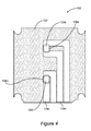
- FIG. 4 is a more detailed illustration of the cartridge of FIG. 1 in which the cartridge includes the TECs disposed on an interconnect board that enables selective control of multiple different subsets of the TECs in the array of TECs in accordance with another embodiment of the present disclosure;
- FIG. 5 is a more detailed illustration of the cartridge of FIG. 1 in which the cartridge includes the TECs disposed on an interconnect board that enables selective control of multiple different subsets of the TECs in accordance with another embodiment of the present disclosure;
- FIG. 6 is a more detailed illustration of the cartridge of FIG. 1 in which the cartridge includes a single TEC disposed on an interconnect board in accordance with another embodiment of the present disclosure
- FIG. 7 is a more detailed illustration of the cartridge of FIG. 1 in which the cartridge includes four TECs disposed on an interconnect board in accordance with another embodiment of the present disclosure
- FIG. 8 is a more detailed illustration of the cartridge of FIG. 1 in which the cartridge includes six TECs disposed on an interconnect board in accordance with another embodiment of the present disclosure
- FIG. 9 shows the interconnect board of FIG. 3 without the TECs in accordance with one embodiment of the present disclosure
- FIG. 10 illustrates the interconnect board of FIG. 4 without the TECs in accordance with another embodiment of the present disclosure
- FIG. 11 shows the interconnect board of FIG. 5 without the TECs in accordance with another embodiment of the present disclosure
- FIG. 12 illustrates the interconnect board of FIG. 6 without the TEC in accordance with another embodiment of the present disclosure
- FIG. 13 illustrates the interconnect board of FIG. 7 without the TECs in accordance with another embodiment of the present disclosure
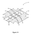
- FIG. 14 shows the interconnect board of FIG. 8 without the TECs according to another embodiment of the present disclosure
- FIG. 15 illustrates an example of one system component layout detailing various operating states, inputs, and outputs of the controller of FIG. 1 according to one embodiment of the present disclosure
- FIG. 16 is a more detailed illustration of the operation of the controller of FIG. 1 when operating in the various operating states of FIG. 15 according to one embodiment of the present disclosure
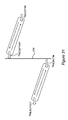
- FIG. 17 illustrates a method of operating the controller of FIG. 1 to maintain the temperature of the cooling chamber at a set point temperature in accordance with one embodiment of the present disclosure
- FIG. 18 illustrates a method of operating the controller of FIG. 1 to maintain the temperature of the cooling chamber at a set point temperature in accordance with another embodiment of the present disclosure
- FIG. 19 illustrates a method of operating the controller of FIG. 1 to monitor a temperature of one or more components of the heat exchanger of FIG. 1 to detect an over-temperature condition and, in response, take action to lower the temperature of the one or more components of the heat exchanger in accordance with one embodiment of the present disclosure
- FIGS. 20A through 20C illustrate a thermoelectric refrigeration system having multiple parallel heat exchangers in accordance with another embodiment of the present disclosure
- FIG. 21 illustrates a thermoelectric refrigeration system that includes two cooling chambers each having separate, thermally-coupled heat sinks in accordance with another embodiment of the present disclosure
- FIG. 22 is a more detailed illustration of the heat exchanger of FIG. 1 in accordance with one embodiment of the present disclosure
- FIGS. 23 and 24 graphically illustrate a thermal diode effect of the accept loop and the reject loop coupled to the heat exchanger of FIG. 22 according to one embodiment of the present disclosure
- FIG. 25 illustrates a thermal diode effect of a hybrid heat exchanger in accordance with one embodiment of the present disclosure
- FIGS. 26 through 29 are schematics illustrating a configuration of a cold side heat sink of the heat exchangers of FIGS. 1 and 21 in accordance with one embodiment of the present disclosure
- FIG. 30 illustrates a heat exchanger having physically separated hot side and cold side heat sinks that are thermally coupled via a heat conduit according to one embodiment of the present disclosure
- FIG. 31 is a schematic illustrating heat flow in the heat exchanger of FIG. 30 according to one embodiment of the present disclosure
- FIGS. 32 and 33 illustrate embodiments of a thermoelectric refrigeration system that utilizes the heat exchanger of FIG. 30 ;
- FIG. 34 is a block diagram for the controller of FIG. 1 in accordance with one embodiment of the present disclosure.
- FIG. 1 illustrates a thermoelectric refrigeration system 100 according to one embodiment of the present disclosure.
- the thermoelectric refrigeration system 100 includes a cooling chamber 102 , a heat exchanger 104 , and a controller 106 that controls cooling within the cooling chamber 102 .
- the heat exchanger 104 includes a hot side heat sink 108 , a cold side heat sink 110 , and a cartridge 112 including multiple Thermoelectric Coolers (TECs), where each TEC has a cold side that is thermally coupled with the cold side heat sink 110 and a hot side that is thermally coupled with the hot side heat sink 108 .
- the TECs are preferably thin film devices.
- the activated TEC(s) operates to heat the hot side heat sink 108 and cool the cold side heat sink 110 to thereby facilitate heat transfer to extract heat from the cooling chamber 102 . More specifically, when one or more of the TECs are activated, the hot side heat sink 108 is heated to thereby create an evaporator and the cold side heat sink 110 is cooled to thereby create a condenser.
- the cold side heat sink 110 facilitates heat extraction from the cooling chamber 102 via an accept loop 114 coupled with the cold side heat sink 110 .
- the accept loop 114 is thermally coupled to an interior wall 115 of the thermoelectric refrigeration system 100 .
- the interior wall 115 defines the cooling chamber 102 .
- the accept loop 114 is either integrated into the interior wall 115 or integrated directly onto the surface of the interior wall 115 .
- the accept loop 114 is formed by any type of plumbing that allows for a cooling medium (e.g., a two-phase coolant) to flow or pass through the accept loop 114 .
- the accept loop 114 may be formed of, for example, copper tubing, plastic tubing, stainless steel tubing, aluminum tubing, or the like.
- the condenser formed by the cold side heat sink 110 and the accept loop 114 operates according to any suitable heat exchange technique.
- the accept loop 114 operates in accordance with thermosiphon principles (i.e., acts as a thermosiphon) such that the cooling medium travels from the cold side heat sink 110 through the accept loop 114 and back to the cold side heat sink 110 to thereby cool the cooling chamber 102 using two-phase, passive heat transport.
- passive heat exchange occurs through natural convection between the cooling medium in the accept loop 114 and the cooling chamber 102 .
- the cooling medium is in liquid form when the cooling medium comes into thermal contact with the cooling chamber 102 .
- passive heat exchange occurs between the environment in the cooling chamber 102 and the cooling medium within the accept loop 114 such that the temperature in the cooling chamber 102 decreases and the temperature of the cooling medium increases and/or undergoes a phase change.
- the temperature of the cooling medium increases, the density of the cooling medium decreases, such as through evaporation.
- the cooling medium moves in an upward direction via buoyancy forces in the accept loop 114 towards the heat exchanger 104 and specifically towards the cold side heat sink 110 .
- the cooling medium comes into thermal contact with the cold side heat sink 110 , where heat exchange occurs between the cooling medium and the cold side heat sink 110 .
- the cooling medium condenses and again flows through the accept loop 114 via gravity in order to extract additional heat from the cooling chamber 102 .
- the accept loop 114 functions as an evaporator when cooling the cooling chamber 102 .
- the heat exchanger 104 includes the cartridge 112 disposed between the hot side heat sink 108 and the cold side heat sink 110 .
- the TECs in the cartridge 112 have hot sides (i.e., sides that are hot during operation of the TECs) that are thermally coupled with the hot side heat sink 108 and cold sides (i.e., sides that are cold during operation of the TECs) that are thermally coupled with the cold side heat sink 110 .
- the TECs within the cartridge 112 effectively facilitate heat transfer between the cold side heat sink 110 and the hot side heat sink 108 . More specifically, when heat transfer occurs between the cooling medium in the accept loop 114 and the cold side heat sink 110 , the active TECs transfer heat between the cold side heat sink 110 and the hot side heat sink 108 .
- the hot side heat sink 108 facilitates rejection of heat to an environment external to the cooling chamber 102 via a reject loop 116 coupled to the hot side heat sink 108 .
- the reject loop 116 is thermally coupled to an outer wall 118 , or outer skin, of the thermoelectric refrigeration system 100 .
- the outer wall 118 is in direct thermal contact with the environment external to the cooling chamber 102 .
- the outer wall 118 is thermally isolated from the accept loop 114 and the interior wall 115 (and thus the cooling chamber 102 ) by, for example, appropriate insulation.
- the reject loop 116 is integrated into the outer wall 118 or integrated onto the surface of the outer wall 118 .
- the reject loop 116 is formed of any type of plumbing that allows a heat transfer medium (e.g., a two-phase coolant) to flow or pass through the reject loop 116 . Due to the thermal coupling of the reject loop 116 and the external environment, the heat transfer medium rejects heat to the external environment as the heat transfer medium flows through the reject loop 116 .
- the reject loop 116 may be formed of, for example, copper tubing, plastic tubing, stainless steel tubing, aluminum tubing, or the like.
- the evaporator formed by the hot side heat sink 108 and the reject loop 116 operates according to any suitable heat exchange technique.
- the reject loop 116 operates in accordance with thermosiphon principles (i.e., acts as a thermosiphon) such that the heat transfer medium travels from the hot side heat sink 108 through the reject loop 116 and back to the hot side heat sink 108 to thereby reject heat using two-phase, passive heat transport.
- the hot side heat sink 108 transfers the heat received from the cold side heat sink 110 to the heat transfer medium within the reject loop 116 .
- the heat transfer medium changes phase and travels through the reject loop 116 and comes into thermal contact with the outer wall 118 such that heat is expelled to the environment external to the cooling chamber 102 .
- passive heat exchange occurs between the heat transfer medium in the reject loop 116 and the external environment.
- the passive heat exchange causes condensation of the heat transfer medium within the reject loop 116 , such that the heat transfer medium travels back to the heat exchanger 104 by force of gravity.
- the reject loop 116 functions as a condenser when rejecting heat to the environment external to the cooling chamber 102 .
- the heat exchanger 104 is not in direct thermal contact with the cooling chamber 102 and is instead thermally isolated from the cooling chamber 102 .
- the heat exchanger 104 is not in direct thermal contact with the outer wall 118 and is instead thermally isolated from the outer wall 118 .
- the heat exchanger 104 is thermally isolated from both the cooling chamber 102 and the outer wall 118 of the thermoelectric refrigeration system 100 . Importantly, this provides a thermal diode effect by which heat is prevented from leaking back into the cooling chamber 102 when the TECs are deactivated.
- the controller 106 operates to control the TECs within the cartridge 112 in order to maintain a desired set point temperature within the cooling chamber 102 .
- the controller 106 operates to selectively activate/deactivate the TECs, selectively control an input current of the TECs, and/or selectively control a duty cycle of the TECs to maintain the desired set point temperature.
- the controller 106 is enabled to separately, or independently, control one or more and, in some embodiments, two or more subsets of the TECs, where each subset includes one or more different TECs.
- the controller 106 may be enabled to separately control a first individual TEC, a second individual TEC, and a group of two TECs (i.e., a first and a second individual TEC and a group of two TECs).
- the controller 106 can, for example, selectively activate one, two, three, or four TECs independently, at maximized efficiency, as demand dictates.
- the controller 106 may be enabled to separately and selectively control: (1) activation/deactivation of the first individual TEC, an input current of the first individual TEC, and/or a duty cycle of the first individual TEC; (2) activation/deactivation of the second individual TEC, an input current of the second individual TEC, and/or a duty cycle of the second individual TEC; and (3) activation/deactivation of the group of two TECs, an input current of the group of two TECs, and/or a duty cycle of the group of two TECs.
- the controller 106 preferably controls the TECs to enhance an efficiency of the thermoelectric refrigeration system 100 .
- the controller 106 may control the TECs to maximize efficiency when operating in a steady state mode, such as when the cooling chamber 102 is at the set point temperature or within a predefined steady state temperature range.
- the controller 106 may control the TECs to achieve a desired performance such as, for example, maximizing heat extraction from the cooling chamber 102 , providing a tradeoff between pull down/recovery times and efficiency, or the like.
- FIG. 2 is a graph that illustrates cooling capacity (Q) and cooling efficiency (COP) of a TEC versus an input current of a TEC.
- the cooling efficiency is more specifically represented by a Coefficient of Performance (COP).
- Q cooling capacity
- COP Coefficient of Performance
- the TEC operates at Q max when a corresponding maximum current I max is provided to the TEC.
- FIG. 2 also illustrates the COP of the TEC as a function of current.
- the COP of a TEC is a ratio of heat removed over an amount of work input to the TEC to remove the heat.
- the amount of heat, or capacity, (Q) at which the COP of the TEC is maximized is denoted as Q COPmax .
- the TEC operates at Q COPmax when a current I COPmax is provided to the TEC.
- the efficiency, or COP, of the TEC is maximized when the current I COPmax is provided to the TEC such that the TEC operates at Q COPmax .
- the controller 106 controls the TECs within the cartridge 112 such that, during steady state operation, one or more of the TECs are activated and operated at Q COPmax and the remaining TECs are deactivated to thereby maximize efficiency.
- the number of TECs activated, and conversely the number of TECs deactivated, is dictated by demand.
- one or more and possibly all of the TECs within the cartridge 112 are activated and operated according to a desired performance profile.
- One example of the desired performance profile is that all of the TECs are activated and operated at Q max in order to minimize pull down or recovery time.
- the desired performance profile may alternatively provide a tradeoff between pull down or recovery time and efficiency where, for example, all of the TECs are activated and are operated at a point between Q COPmax and Q max . Note that, as discussed below, control of the TECs is not limited to these examples.
- FIG. 2 illustrates the cooling capacity and cooling efficiency of a single TEC.
- Increasing the number of TECs linearly increases the heat removal capacity without affecting the operating COP of the thermoelectric refrigeration system 100 employing the TECs.
- the thermoelectric refrigeration system 100 includes four TECs, then the heat removal capacity of the thermoelectric refrigeration system 100 is increased fourfold in comparison to an embodiment of the thermoelectric refrigeration system 100 that includes a single TEC while allowing the entire system to, in some preferred embodiments, operate between off, Q COPmax , and Q max .
- the cartridge 112 of FIG. 1 Before discussing the details of the operation of the controller 106 to separately and selectively control the TECs, it is beneficial to discuss embodiments of the cartridge 112 of FIG. 1 that enable separate and selective control of the TECs. Note that while the following discussion of the cartridge 112 is with respect to the thermoelectric refrigeration system 100 of FIG. 1 , the cartridge 112 is not limited to use in the thermoelectric refrigeration system 100 of FIG. 1 nor thermoelectric refrigeration in general. For instance, the cartridge 112 may be utilized in heat recovery or power generation applications.
- the TECs in the cartridge 112 are used to regulate the temperature of the cooling chamber 102 .
- the thermoelectric refrigeration system 100 utilizes multiple TECs.
- the use of multiple TECs is beneficial over the use of a single large TEC because the multiple TECs can be separately controlled to provide the desired performance under varying conditions.
- a single over-sized TEC that is designed to provide a maximum desired capacity for pull down or recovery does not provide this flexibility.
- the single over-sized TEC would typically operate at a low capacity point that corresponds to a low COP value. In other words, the over-sized TEC would operate inefficiently.
- the controller 106 is enabled to separately control subsets of the TECs in the cartridge 112 in order to maximize efficiency during steady state conditions.
- FIGS. 3 through 5 illustrate embodiments of the cartridge 112 that enable the controller 106 to separately and selectively control different subsets of the TECs according to a desired control scheme. Note, however, that the embodiments of FIGS. 3 through 5 are only examples.
- the cartridge 112 may be configured to hold any number of TECs and to allow any number of subsets of the TECs to be separately controlled. Each subset generally includes one or more TECs. Further, the different subsets may include the same number or different numbers of TECs.
- the cartridge 112 includes TECs 120 a through 120 f (more generally referred to herein collectively as TECs 120 and individually as TEC 120 ) disposed on an interconnect board 122 .
- the TECs 120 are thin film devices. Some non-limiting examples of thin film TECs are disclosed in U.S. Pat. No. 8,216,871, entitled METHOD FOR THIN FILM THERMOELECTRIC MODULE FABRICATION, which is hereby incorporated herein by reference in its entirety.
- the interconnect board 122 includes electrically conductive traces 124 a through 124 d (more generally referred to herein collectively as traces 124 and individually as trace 124 ) that define four subsets of the TECs 120 a through 120 f .
- the TECs 120 a and 120 b are electrically connected in series with one another via the trace 124 a and, as such, form a first subset of the TECs 120 .
- the TECs 120 c and 120 d are electrically connected in series with one another via the trace 124 b and, as such, form a second subset of the TECs 120 .
- the TEC 120 e is connected to the trace 124 d and, as such, forms a third subset of the TECs 120
- the TEC 120 f is connected to the trace 124 c and, as such, forms a fourth subset of the TECs 120 .
- the controller 106 FIG.
- the first subset of TECs 120 i.e., the TECs 120 a and 120 b
- selectively control the second subset of the TECs 120 i.e., the TECs 120 c and 120 d
- selectively control the third subset of the TECs 120 i.e., the TEC 120 e
- selectively control the fourth subset of the TECs 120 i.e., the TEC 120 f
- the controller 106 can selectively activate/deactivate the TECs 120 a and 120 b by either removing current from the trace 124 a (deactivate) or by applying a current to the trace 124 a (activate), selectively increase or decrease the current applied to the trace 124 a while the TECs 120 a and 120 b are activated, and/or control the current applied to the trace 124 a in such a manner as to control a duty cycle of the TECs 120 a and 120 b while the TECs 120 a and 120 b are activated (e.g., Pulse Width Modulation of the current).
- Pulse Width Modulation of the current e.g., Pulse Width Modulation of the current
- the interconnect board 122 includes openings 126 a and 126 b (more generally referred to herein collectively as openings 126 and individually as opening 126 ) that expose bottom surfaces of the TECs 120 a through 120 f .
- openings 126 a and 126 b When disposed between the hot side heat sink 108 ( FIG. 1 ) and the cold side heat sink 110 ( FIG. 1 ), the openings 126 a and 126 b enable the bottom surfaces of the TECs 120 a through 120 f to be thermally coupled to the appropriate heat sink 108 or 110 .
- the controller 106 can selectively activate or deactivate any combination of the subsets of the TECs 120 by applying or removing current from the corresponding traces 124 a through 124 d . Further, the controller 106 can control the operating points of the active TECs 120 by controlling the amount of current provided to the corresponding traces 124 a through 124 d .
- the controller 106 provides the current I COPmax to the trace 124 a to thereby activate the TECs 120 a and 120 b and operate the TECs 120 a and 120 b at Q COPmax and removes current from the other traces 124 b through 124 d to thereby deactivate the other TECs 120 c through 120 f.
- the cartridge 112 includes the TECs 120 a through 120 f .
- the cartridge 112 may include any number of TECs 120 .
- the cartridge 112 includes the interconnect board 122 having only two TECs 120 , the TECs 120 e and 120 f .
- the controller 106 FIG. 1
- the cartridge 112 can include only four TECs 120 , such as the TECs 120 c through 120 f , as shown with reference to FIG. 5 .
- the interconnect board 122 includes the traces 124 b through 124 d , which provide current to the TECs 120 c through 120 f , respectively.
- the corresponding subsets of the TECs 120 can be controlled by the controller 106 by providing the appropriate currents to the traces 124 b through 124 d.
- FIGS. 3 through 5 illustrate embodiments of the cartridge 112 that enable selective control of different TECs on the cartridge 112
- FIGS. 6 through 8 illustrate embodiments of the cartridge 112 that may be utilized if selective control is not needed.
- the input current of the TECs and/or a duty cycle of the TECs may be varied to provide a desired capacity, a desired efficiency, or some tradeoff between capacity and efficiency.
- FIG. 6 illustrates an embodiment of the cartridge 112 that includes an interconnect board 128 and a single TEC 130 disposed on the interconnect board 128 .
- An opening 131 in the interconnect board 128 exposes a bottom surface of the TEC 130 .
- the controller 106 ( FIG. 1 ) can control the capacity and efficiency of the TEC 130 by controlling a current input to the TEC 130 via an electrically conductive trace 132 on the interconnect board 128 .
- FIG. 7 illustrates an embodiment of the cartridge 112 that is similar to that of FIG. 6 but where the cartridge 112 includes four TECs. More specifically, the cartridge 112 includes an interconnect board 134 and four TECs 136 disposed on the interconnect board 134 . There are openings 137 in the interconnect board 134 to expose bottom surfaces of the TECs 136 . Again, the controller 112 can control a capacity and efficiency of the TECs 136 by controlling a current input to the TECs 136 and/or a duty cycle of the TECs 136 via an electrically conductive trace 138 on the interconnect board 134 .
- FIG. 8 illustrates yet another example of the cartridge 112 that is similar to that of FIGS. 6 and 7 but where the cartridge 112 includes six TECs. More specifically, the cartridge 112 includes an interconnect board 140 and six TECs 142 disposed on the interconnect board 140 . There are openings 143 in the interconnect board 140 to expose bottom surfaces of the TECs 142 . Again, the controller 112 can control a capacity and efficiency of the TECs 142 by controlling a current input to the TECs 142 and/or a duty cycle of the TECs 142 via an electrically conductive trace 144 on the interconnect board 140 . Note that the embodiments of FIGS. 6 through 8 are only examples. The cartridge 112 may be configured to include any number of TECs or conductive traces in series or parallel configuration.
- FIGS. 9 through 14 illustrate the interconnect boards 122 , 128 , 134 , and 140 of FIGS. 3 through 8 , respectively, but without TECs attached to the interconnect boards.
- FIGS. 9 through 14 more clearly illustrate the openings 126 , 131 , 137 , and 143 in the interconnect boards that expose the bottom surfaces of the TECs or, in other words, enable thermal coupling between the bottom surfaces of the TECs and the appropriate heat sink 108 or 110 .
- FIGS. 9 through 14 also illustrate contacts 146 , 148 , 150 , and 152 that enable electrical and mechanical connection between the interconnect boards 122 , 128 , 134 , and 140 and corresponding TECs.
- the cartridge 112 is the cartridge 112 of FIG. 3 , which enables selective control of multiple different subsets of the TECs 120 . Note, however, that the use of the cartridge 112 of FIG. 3 is only an example.
- FIG. 15 illustrates the operation of the controller 106 according to one embodiment of the present disclosure.
- the controller 106 receives temperature data from temperature inputs 154 and 156 .
- the temperature inputs 154 and 156 can be any type of temperature sensors.
- the temperature data includes a temperature (T CH ) of the cooling chamber 102 and a temperature (T R ) on the reject side, or hot side, of the heat exchanger 104 .
- the reject side of the heat exchanger 104 is the hot side of the heat exchanger 104 .
- the temperature (T R ) may be a temperature of the hot side heat sink 108 .
- the controller 106 determines a current mode of operation of the thermoelectric refrigeration system 100 .
- the current mode of operation is one of a pull down mode 158 , a steady state mode 160 , an over temperature mode 162 , and a recovery mode 163 .
- the pull down mode 158 generally occurs when the thermoelectric refrigeration system 100 is first powered on.
- the steady state mode 160 occurs when the temperature of the cooling chamber 102 is at or near the desired set point temperature. In particular, the temperature of the cooling chamber 102 is at or near the desired set point temperature when the temperature of the cooling chamber 102 is within a predefined steady state range that includes the set point temperature (e.g., the set point temperature of the cooling chamber 102 ⁇ 2 degrees).
- the over temperature mode 162 is when the temperature on the reject side of the heat exchanger 104 is above a predefined maximum allowable temperature.
- the over temperature mode 162 is a safety mode during which the temperature of the reject side of the heat exchanger 104 , and thus the hot side temperature of the TECs 120 , is reduced in order to protect the TECs 120 from damage.
- the recovery mode 163 is when the temperature of the cooling chamber 102 increases outside of the steady state range due to, for example, heat leak into the cooling chamber 102 , opening of the door of the cooling chamber 102 , or the like.
- FIG. 16 The operation of the controller 106 in the different modes 158 , 160 , 162 , and 163 in one embodiment of the present disclosure is illustrated in FIG. 16 .
- the controller 106 when operating in the pull down mode 158 , the controller 106 controls the currents to all of the TECs 120 such that all of the TECs 120 operate at a power level between Q COPmax and Q max as the desired performance profile dictates. In other words, the controller 106 causes a current between I COPmax and I max to be provided to all of the TECs 120 .
- the controller 106 determines when the thermoelectric refrigeration system 100 is in the pull down mode 158 based on, for example, being initially powered on, such as when the thermoelectric refrigeration system 100 is first purchased or after the thermoelectric refrigeration system 100 is powered on after becoming disconnected from a power source.
- the controller 106 maintains all of the TECs 120 at a power level between Q COPmax and Q max until the temperature of the cooling chamber 102 is pulled down to the set point temperature or within an acceptable range of the set point temperature, as shown with reference to 164 .
- the controller 106 controls the operation of the TECs 120 such that all of the TECs 120 operate at Q COPmax by causing the current I COPmax to be provided to all of the TECs 120 . Moreover, the controller 106 may reduce the number of TECs 120 that are activated once the cooling chamber 102 is pulled down to the set point temperature.
- the controller 106 determines when the thermoelectric refrigeration system 100 is in the steady state mode 160 .
- the thermoelectric refrigeration system 100 is in the steady state mode 160 if the temperature of the cooling chamber 102 is equal to the set point temperature or within a predetermined range of the set point temperature.
- the controller 106 sets the required number of the TECs 120 to Q COPmax as required by demand. In this example, all of the TECs 120 are operated at Q COPmax in the steady state mode 160 .
- Q COPmax >Q leak as shown with reference to 166 , the temperature of the cooling chamber 102 will continue to decrease.
- the controller 106 reduces the duty cycle of the activated TECs 120 as shown with reference to 168 .
- Q COPmax ⁇ Q leak as shown with reference to 170 , the temperature of the cooling chamber 102 will increase.
- the controller 106 increases the number of active TECs 120 as available and then the current provided to the active TECs 120 to a value between I COPmax and I max as shown with reference to 172 .
- Q leak refers to the amount of heat leaking into the cooling chamber 102 , such as heat passing through a seal of a door of the cooling chamber 102 , natural heat conduction through the cooling chamber 102 , or the like.
- the controller 106 also determines if the cooling chamber 102 is in the over temperature mode 162 based on the temperature data from the temperature input 156 .
- the temperature at the reject side of the heat exchanger 104 is monitored to ensure that the temperature at the reject side of the heat exchanger 104 does not exceed the predetermined maximum allowable temperature.
- the temperature of the reject side of the heat exchanger 104 may exceed the predetermined maximum allowable temperature when, for example, the cooling chamber 102 does not cool down, such as if the door to the cooling chamber 102 is not properly closed, or the like.
- the controller 106 determines that the temperature at the reject side of the heat exchanger 104 exceeds the predetermined maximum allowable temperature, in an operation 174 , the controller 106 decreases the temperature at the reject side of the heat exchanger 104 by deactivating some or all of the TECs 120 that are facilitating cooling or by reducing the current being provided to the TECs 120 . For example, if all of the TECs 120 are operating, either at Q COPmax or Q max , the controller 106 may deactivate one or more of the TECs 120 or preferably all of the TECs 120 .
- the controller 106 may deactivate the TECs 120 e and 120 f such that only the TECs 120 a and 120 b are operating at Q max and facilitating heat extraction from the cooling chamber 102 .
- the controller 106 may deactivate the TECs 120 c and 120 d and then also activate the TEC 120 e in order to maintain the temperature of the cooling chamber 102 as close as to the set point temperature as possible without harming the cartridge 112 . It should be noted that the controller 106 may deactivate any number of active TECs 120 and activate any number of the inactive TECs 120 in response to determining that the temperature of the heat exchanger 104 exceeds the maximum allowable temperature.
- the controller 106 may reduce the current being provided to the TECs 120 in addition to or as an alternative to deactivating some or all of the TECs 120 .
- the controller 106 may decrease the amount of current being provided to each of the TECs 120 . For example, if all of the TECs 120 are operating at Q max , the controller 106 may reduce the current from I max to a value that is between I COPmax and I max .
- the controller 106 may only reduce the current provided to some of the TECs 120 in order to reduce the temperature of the heat exchanger 104 .
- the controller 106 may also deactivate some of the TECs 120 and simultaneously decrease the current to some or all of the TECs 120 that are still activated if the temperature of the heat exchanger 104 exceeds the predetermined maximum allowable temperature.
- the controller 106 switches the active TECs 120 from operating at Q COPmax to operating at Q max as shown at operation 175 .
- the recovery mode 163 occurs when, during steady state operation, the controller 106 receives temperature data from the temperature input 154 indicating that the temperature within the cooling chamber 102 has significantly increased above the set point temperature within a short period of time.
- the thermoelectric refrigeration system 100 may enter the recovery mode 163 when the temperature within the cooling chamber 102 increases above an upper threshold of the steady state range of temperatures (e.g., increases above the set point temperature plus some predefined value that defines the upper threshold of the desired steady state range).
- the controls 164 , 166 , 168 , 170 , 172 , 174 , and 175 illustrated in FIG. 16 for the different modes 158 , 160 , 162 , and 163 are only examples.
- the manner in which the controller 106 controls the TECs 120 in each of the modes 158 , 160 , 162 , and 163 may vary depending on the particular implementation. In general, as discussed above, the controller 106 controls the TECs 120 to reduce the temperature of the cooling chamber 102 when in either the pull down mode 158 or the recovery mode 163 . The exact manner in which this is done may vary.
- the controller 106 can activate all of the TECs 120 at Q max with a 100% duty cycle (always on). Conversely, if a trade-off between pull down or recovery time and efficiency is desired, the controller 106 can, for example, activate all of the TECs 120 at Q COPmax with a 100% duty cycle (always on) or at anywhere in between Q COPmax and Q max . When in the steady state mode 160 , the controller 106 generally operates to maintain the set point temperature in an efficient manner.
- the controller 106 can operate the required number of the TECs 120 (e.g., all of the TECs 120 or less than all of the TECs 120 ) at Q COPmax based on load.
- This predetermined number of the TECs 120 is a number of the TECs 120 that is required to maintain the set point temperature by operating at or near Q COPmax . If not all of the TECs 120 are needed during the steady state mode 160 , then the unneeded TECs 120 are deactivated.
- the controller 106 can fine tune the operation of the activated TECs 120 to precisely maintain the set point temperature by, for example, slightly increasing or decreasing the input current of the activated TECs 120 such that the activated TECs 120 operate slightly above Q COPmax or by increasing or decreasing the duty cycle of the activated TECs 120 to compensate for Q leak .
- the thermoelectric refrigeration system 100 also includes a user interface (UI) 176 , a power source 178 , an accessory (acc) 180 , and power electronics 182 .
- the user interface 176 allows a user to input various control parameters associated with the thermoelectric refrigeration system 100 . These control parameters include the set point temperature of the cooling chamber 102 . In some embodiments, the control parameters may additionally include values for the steady state range of temperatures. Note that, in some embodiments, the user interface 176 may additionally allow the user or a manufacturer of the thermoelectric refrigeration system 100 to define the maximum allowable temperature for the reject side of the heat exchanger 104 , the current values associated with I COPmax and I max , and/or the like. However, it should be noted that some or all of the control parameters may be programmed or hard-coded into the controller 106 .
- the power source 178 provides power to the controller 106 , the accessory 180 , and the power electronics 182 .
- the accessory 180 may be a chamber light or a communication module for expanded capabilities.
- the accessory 180 may communicate with remote devices, such as, but not limited to: a cellular telephone, a remotely located computing device, or even other appliances and thermoelectric refrigeration systems.
- the accessory 180 can provide operational parameters (e.g., the temperature data) of the thermoelectric refrigeration system 100 and the cooling chamber 102 to a remote device or entity.
- the accessory 180 may communicate operational parameters of the thermoelectric refrigeration system 100 to the other thermoelectric refrigeration systems, such as the set point temperature, upper and lower thresholds of the set point temperature, a maximum allowable temperature of the cooling chamber 102 , the maximum allowable temperature of the reject side of the heat exchanger 104 , or the like.
- the power electronics 182 generally operate to provide current to the TECs 120 in response to control inputs from the controller 106 . More specifically, the power electronics 182 independently provide current to each of the subsets of the TECs 120 . In one embodiment, the duty cycles of the different subsets of the TECs 120 are also controlled. In this case, the power electronics 182 may provide a pulse width modulation function by which the duty cycles of the different subsets of the TECs 120 are controlled.
- a method of operation of the controller 106 to maintain the cooling chamber 102 at the set point temperature is illustrated in accordance with one embodiment of the present disclosure.
- the temperature data corresponding to the temperature within the cooling chamber 102 and the temperature at the reject side of the heat exchanger 104 is received (step 1000 ).
- a thermocouple, or any other type of temperature sensor may be used to determine the temperature of the cooling chamber 102 and provide the temperature as temperature data to the controller 106 in step 1000 via the temperature input 154 .
- a thermocouple, or any other type of temperature sensor may be used to determine the temperature of the reject side of the heat exchanger 104 and provide the temperature as temperature data to the controller 106 in step 1000 via the temperature input 156 .
- the controller 106 In response to receiving the temperature data, the controller 106 selectively controls the TECs based on the temperature data (step 1002 ). In general, the controller 106 selectively controls one or more and, in some preferred embodiments, two or more different subsets of the TECs based on the temperature data and the set point temperature for the cooling chamber 102 . Using the TECs 120 in the cartridge 112 of FIG. 3 as an example, the controller 106 selectively, or separately, controls the different subsets of the TECs 120 . More specifically, as discussed above, the controller 106 determines whether the thermoelectric refrigeration system 100 is in the pull down mode 158 , the steady state mode 160 , or the recovery mode 163 based on the temperature data and the set point temperature for the cooling chamber 102 .
- the controller 106 determines that the thermoelectric refrigeration system 100 is in either the pull down mode 158 or the recovery mode 163 , the controller 106 controls the TECs 120 to decrease the temperature of the cooling chamber 102 by either activating TECs 120 that are currently deactivated, increasing the current provided to the activated TECs 120 , and/or increasing the duty cycle of the activated TECs 120 . If the controller 106 determines that the thermoelectric refrigeration system 100 is in the steady state mode 160 , the controller 106 controls the TECs 120 to maintain the set point temperature.
- the controller 106 may, for example, activate or deactivate the different subsets of the TECs 120 , increase or decrease the current provided to the different subsets of the activated TECs 120 , and/or increase or decrease the duty cycle of the different subsets of the activated TECs 120 as needed to maintain the set point temperature.
- the controller 106 may activate additional subsets of the inactive TECs 120 c , 120 d , and 120 f and operate the newly activated TECs 120 at Q COPmax . If further cooling capacity is needed, the controller 106 may then increase the current provided to the active TECs 120 a , 120 b , 120 c , 120 d , 120 e , and 120 f up to I max in order to pull the temperature of the cooling chamber 102 down to the set point temperature as soon as possible.
- the method returns to step 1000 and the controller 106 once again receives the temperature data.
- the controller 106 decreases the current provided to the TECs 120 a , 120 b , and 120 e from I max to I COPmax such that the TECs 120 a , 120 b , and 120 e operate at Q COPmax for the steady state mode 160 in step 1002 .
- the controller 120 deactivates the TECs 120 c , 120 d , and 120 f , which in this example are unused in the steady state mode 160 .
- the controller 106 continually repeats this process to maintain the set point temperature in the cooling chamber 102 .
- the controller 106 is configured or enabled to control the TECs 120 according multiple control schemes.
- the control schemes include independently controlling activation and deactivation of the different subsets of the TECs 120 , independently controlling a current provided to each subset of the TECs 120 , and/or independently controlling a duty cycle of each subset of the TECs 120 .
- the controller 106 selects one or more control schemes based on the temperature of the cooling chamber 102 and, in some embodiments, the temperature at the reject side of the heat exchanger 104 , as well as a desired performance profile.
- the desired performance profile may be programmable or hard-coded into the controller 106 .
- the desired performance profile dictates how the TECs 120 are controlled (e.g., maximum efficiency, maximum capacity, or somewhere between maximum efficiency and maximum capacity) for the different modes of operation.
- the controller 106 controls the different subsets of the TECs 120 according to the selected control scheme(s).
- the controller 106 can control any combination of activation/deactivation, current, and duty cycle for each mode of operation.
- the controller 106 may select the control scheme of activation/deactivation of the TECs 120 based on the temperature of the cooling chamber 102 and a desired performance profile of maximizing efficiency during the steady state mode 160 . In this case, the controller 106 then activates one or more of the subsets of TECs 120 and, in some embodiments, deactivates one or more other subsets of the TECs 120 .
- the controller 106 may choose to control the current and/or duty cycle of the activated TECs 120 during the steady state mode 160 , in which case the controller 106 independently controls the current provided to each of the activated subsets of TECs 120 and/or the duty cycle of each of the activated subsets of TECs 120 .
- the controller 106 may select the control scheme of activation/deactivation of the TECs 120 based on the temperature of the cooling chamber 102 and a desired performance profile (e.g., minimizing pull down or recovery time). In this case, the controller 106 activates additional subsets of the TECs 120 not activated during the steady state mode 160 .
- controller 106 may choose to control the current and/or duty cycle of the activated subsets of TECs 120 for the pull down mode 158 or the recovery mode 163 , in which case the controller 106 independently controls the current of each of the activated subsets of TECs 120 and/or the duty cycle of each of the activated subsets of TECs 120 .
- FIG. 18 is a flow chart that illustrates a method of operation of the controller 106 to maintain the cooling chamber 102 at the set point temperature according to another embodiment of the present disclosure.
- the temperature data for the cooling chamber 102 and the reject side of the heat exchanger 104 is received (step 1100 ).
- the controller 106 determines whether the temperature of the cooling chamber 102 is greater than an upper threshold of the steady state range for the temperature of the cooling chamber 102 (step 1102 ).
- the steady state range is an acceptable temperature range for the cooling chamber 102 that includes the set point temperature.
- the steady state range may be the set point temperature plus or minus a predefined offset (e.g., 2 degrees). If the temperature of the cooling chamber 102 is not greater than the upper threshold of the steady state range, the controller 106 determines whether the temperature of the cooling chamber 102 is greater than a lower threshold of the steady state range (step 1104 ).
- the process returns to step 1100 .
- the controller 106 controls the TECs 120 to increase the temperature of the cooling chamber 102 (step 1106 ).
- the controller 106 increases the temperature of the cooling chamber 102 by deactivating one or more of the TECs, decreasing the current input to one or more of the TECs 120 , and/or decreasing the duty cycle of one or more of the TECs 120 . Since the controller 106 can selectively control the different subsets of the TECs 120 , the controller 106 has substantial flexibility in how the temperature of the cooling chamber 102 is increased. After controlling the TECs 120 to increase the temperature of the cooling chamber 102 , the process returns to step 1100 and is repeated.
- step 1108 determines whether the temperature of the cooling chamber 102 is greater than a predetermined maximum allowable temperature for the cooling chamber 102 (step 1108 ). If so, the process proceeds to step 1112 . If not, the controller 106 controls the TECs 120 to decrease the temperature of the cooling chamber 102 (step 1110 ).
- the controller 106 controls the TECs 120 to decrease the temperature of the cooling chamber 102 by activating one or more previously deactivated TECs 120 , increasing the current input to one or more of the activated TECs 120 from I COPmax to a value that is greater than I COPmax (e.g., I max ), and/or increasing the duty cycle of one or more of the activated TECs 120 .
- the controller 106 independently controls the different subsets of the TECs 120 .
- the controller 106 can decrease the temperature of the cooling chamber 102 by increasing the current input to the first subset of the TECs 120 from I COPmax to a value greater than I COPmax (e.g., I max ), increasing a duty cycle of the first subset of the TECs 120 , activating the second subset of the TECs 120 to operate at Q COPmax or a capacity greater than Q COPmax with a desired duty cycle (e.g., always on), activating the third subset of the TECs 120 to operate at Q COPmax or a capacity greater than Q COPmax with a desired duty cycle (e.g., always on), and/or activating the fourth subset of the TECs 120 to operate at Q COPmax or a capacity greater than Q COPmax
- the controller 106 determines whether the temperature at the reject side of the heat exchanger 104 is greater than the predetermined maximum allowable temperature for the reject side of the heat exchanger 104 (step 1112 ). If so, the controller 106 controls the TECs 120 to lower the temperature of the heat exchanger components (step 1114 ). Specifically, the controller 106 controls the TECs 120 to lower the temperature of the components of the heat exchanger 104 at the reject side (e.g., the hot side heat sink 108 ).
- Lowering the temperature of the components of the heat exchanger 104 may be accomplished by deactivating some or all of the TECs 120 , reducing the current provided to some or all of the TECs 120 , or a combination thereof. The process then returns to step 1100 and is repeated.
- the controller 106 controls the TECs to decrease the temperature of the cooling chamber 102 (step 1116 ).
- the controller 106 controls the TECs 120 to decrease the temperature of the cooling chamber 102 by activating one or more previously deactivated TECs 120 , increasing the current input to one or more of the activated TECs 120 from I COPmax to a value that is greater than I COPmax (e.g., I max ), and/or increasing the duty cycle of one or more of the activated TECs 120 .
- the controller 106 can decrease the temperature of the cooling chamber 102 by increasing the current input to the first subset of the TECs 120 from I COPmax to a value greater than I COPmax (e.g., I max ), increasing a duty cycle of the first subset of the TECs 120 , activating the second subset of the TECs 120 to operate at Q COPmax or a capacity greater than Q COPmax with a desired duty cycle (e.g., always on), activating the third subset of the TECs 120 to operate at Q COPmax or a capacity greater than Q COPmax with a desired duty cycle (e.g., always on), and/or activating the fourth subset of the TECs 120 to operate at Q COPmax or a capacity greater than Q COPmax with a desired duty cycle (e.g., always on), and/or activating the fourth subset of the TECs 120 to operate at Q COPmax or a capacity greater than Q COPmax with
- the temperature data indicates that the cooling chamber 102 is at 0.9° C. and the reject side of the heat exchanger 104 is at 19° C.
- the set point temperature for the cooling chamber 102 is 2.2° C.
- the upper threshold of the steady state range is 5.0° C.
- the lower threshold of the steady state range is 1.0° C.
- the maximum allowable temperature in the cooling chamber 102 is 15° C.
- the maximum allowable temperature at the reject side of the heat exchanger 104 is 20° C.
- the controller 106 first determines that the temperature of the cooling chamber 102 (0.9° C.) does not exceed the upper threshold value of the steady state range (5.0° C.).
- the controller 106 performs step 1104 where the controller 106 determines that the temperature of the cooling chamber 102 (0.9° C.) is less than the lower threshold of the steady state range (1.0° C.). Therefore, the controller 106 performs step 1106 to increase the temperature of the cooling chamber 102 . After performing step 1106 , the controller 106 returns to step 1100 to thereby receive updated temperature data and continue the process.
- the temperature data indicates that the temperature of the cooling chamber 102 is 14° C. and the temperature at the reject side of the heat exchanger 104 is 18° C.
- the set point temperature for the cooling chamber 102 is 2.2° C.
- the upper threshold of the steady state range is 5.0° C.
- the lower threshold of the steady state range is 1.0° C.
- the maximum allowable temperature in the cooling chamber 102 is 15° C.
- the maximum allowable temperature at the reject side of the heat exchanger 104 is 20° C.
- the controller 106 determines that the temperature of the cooling chamber 102 (14° C.) is greater than the upper threshold of the steady state range (5.0° C.).
- the controller 106 performs step 1108 , where the controller 106 determines that the temperature of the cooling chamber 102 (14° C.) is less than the maximum allowable temperature of the cooling chamber 102 (15° C.). Accordingly, the controller 106 performs step 1110 to thereby decrease the temperature of the cooling chamber 102 .
- the temperature data indicates that the temperature of the cooling chamber 102 is 17° C. and the temperature of the heat exchanger 104 is 22° C.
- the set point temperature for the cooling chamber 102 is 2.2° C.
- the upper threshold of the steady state range is 5.0° C.
- the lower threshold of the steady state range is 1.0° C.
- the maximum allowable temperature in the cooling chamber 102 is 15° C.
- the maximum allowable temperature at the reject side of the heat exchanger 104 is 20° C.
- the controller 106 determines that the temperature of the cooling chamber 102 is greater than the upper threshold of the steady state range.
- the controller 106 performs step 1108 , where the controller 106 determines that the temperature of the cooling chamber 102 (17° C.) exceeds the maximum allowable temperature within the cooling chamber 102 (15° C.). Accordingly, the controller 106 performs step 1112 , where the controller 106 determines whether the temperature at the reject side of the heat exchanger 104 exceeds the maximum allowable temperature at the reject side of the heat exchanger 104 .
- the maximum allowable temperature at the reject side of the heat exchanger 104 is a temperature beyond which components of the heat exchanger 104 may overheat and become damaged.
- thermoelectric refrigeration system 100 is trying to pull down the temperature of the cooling chamber 102 to the set point temperature.
- the components of the heat exchanger 104 may not be able to pull down the temperature of the cooling chamber 102 and instead become overworked, thereby overheating (i.e., exceeding the maximum allowable temperature at the reject side of the heat exchanger 104 ).
- Another example of when the temperature at the reject side of the heat exchanger 104 exceeds the maximum allowable temperature at the reject side of the heat exchanger 104 is when proper heat transfer is not occurring between the accept loop 114 and the cooling chamber 102 , such as if there is a clog in the accept loop 114 , if there is an issue with the cooling medium within the accept loop 114 , or the like.
- the temperature at the reject side of the heat exchanger 104 (22° C.) exceeds the maximum allowable temperature at the reject side of the heat exchanger 104 (20° C.). Accordingly, the controller 106 performs step 1114 , where the controller 106 cools the temperature of the components of the heat exchanger 104 .
- FIG. 19 is a flow chart that illustrates a method of operation of the controller 106 to monitor the temperature at the reject side of heat exchanger 104 in accordance with one embodiment of the present disclosure.
- the controller 106 receives temperature data (step 1200 ).
- the temperature data corresponds to the temperature at the reject side of the heat exchanger 104 .
- the controller 106 determines whether the temperature at the reject side of the heat exchanger 104 exceeds the maximum allowable temperature at the reject side of the heat exchanger 104 , as described above with reference to step 1112 of FIG. 18 (step 1202 ). If the temperature at the reject side of the heat exchanger 104 does not exceed the maximum allowable temperature, the process returns to step 1200 and is repeated.
- the controller 106 controls the TECs 120 to thereby reduce the temperature at the reject side of the heat exchanger 104 (step 1204 ).
- the thermoelectric refrigeration system 100 includes a single heat exchange system (i.e., a single heat exchanger 104 , a single accept loop 114 , and a single reject loop 116 ).
- FIGS. 20A through 20C illustrate another embodiment of the thermoelectric refrigeration system 100 that includes two parallel heat exchange systems. Note that while two parallel heat exchange systems are illustrated in the embodiment of FIGS. 20A through 20C , any number of two or more parallel heat exchange systems may be used. As illustrated in FIG. 20A , the two parallel heat exchange systems are the same as the heat exchange system of FIG. 1 .
- the first heat exchange system includes a heat exchanger 104 a that includes a hot side heat sink 108 a , a cold side heat sink 110 a , a cartridge 112 a disposed between the hot side and cold side heat sinks 108 a and 110 a , an accept loop 114 a coupled to the cold side heat sink 110 a , and a reject loop 116 a coupled to the hot side heat sink 108 a .
- the cartridge 112 a includes one or more TECs and preferably multiple TECs that are selectively controlled by the controller 106 .
- the TECs are disposed on an interconnect board that enables selective and independent control of one or more, and preferably two or more, subsets of the TECs in the manner described above with respect to the cartridge 112 of FIG. 1 .
- the second heat exchange system includes a heat exchanger 104 b that includes a hot side heat sink 108 b , a cold side heat sink 110 b , a cartridge 112 b disposed between the hot side and cold side heat sinks 108 b and 110 b , an accept loop 114 b coupled to the cold side heat sink 110 b , and a reject loop 116 b coupled to the hot side heat sink 108 b .
- the cartridge 112 b includes one or more TECs and preferably multiple TECs that are selectively controlled by the controller 106 .
- the TECs are disposed on an interconnect board that enables selective and independent control of one or more, and preferably two or more, subsets of the TECs in the manner described above with respect to the cartridge 112 of FIG. 1 .
- the operation of the two parallel heat exchange systems of FIG. 20A and the control of the TECs in the cartridges 112 a and 112 b is the same as that described above with respect to the corresponding heat exchange system and the cartridge 112 of FIG. 1 . As such, the details are not repeated.
- the parallel heat exchange systems provide an additional degree of freedom for the controller 106 when controlling the TECs in the cartridges 112 a and 112 b . More specifically, in addition to selectively and independently controlling one or more, and preferably two or more, subsets of TECs in the cartridge 112 a , the controller 106 is also enabled to selectively and independently control one or more, and preferably two or more, subsets of TECs in the cartridge 112 b independently from the subset(s) of TECs in the cartridge 112 a .
- the controller 106 may activate some or potentially all of the TECs in the cartridge 112 a preferably at or near (e.g., slightly above or potentially below) Q COPmax and deactivate all of the TECs in the cartridge 112 b , as illustrated in FIG. 20B .
- the controller 106 may activate any previously deactivated TECs in the cartridge 112 a and activate some or potentially all of the TECs in the cartridge 112 b , as illustrated in FIG. 20C .
- the activated TECs are preferably operated at Q COPmax , Q max , or some value between Q COPmax and Q max .
- One non-limiting advantage of the parallel heat exchangers 104 a and 104 b is the ability to completely isolate large numbers of TEC subsets while at the same time providing for large recovery capacity without suffering from parasitic losses associated with deactivated TECs located in the same heat exchanger 104 a , 104 b as the active TECs.
- Another non-limiting advantage of the parallel heat exchangers 104 a and 104 b is related to maximizing efficiency by better balancing of the different control regimes to the relevant heat exchanger volume/dissipation area.
- arrays of TECs may be cascaded in order to maintain different cooling chambers at different set point temperatures.
- a single thermoelectric refrigeration system may have a first cooling chamber and a second cooling chamber each having different set point temperatures.
- a first set of TECs e.g., TECs in a first cartridge
- a second set of TECs e.g., TECs in a second cartridge
- the first and second sets of the TECs are thermally coupled to one another via cascaded heat sinks.
- the first set of TECs extract heat from the first cooling chamber and operate to reject the extracted heat to an environment external to the first cooling chamber.
- the second set of TECs extract heat from the second cooling chamber and then operate to reject the extracted heat to the first set of TECs.
- the first set of TECs operates to reject the heat extracted from the second cooling chamber to an environment external to the first and second cooling chambers.
- the first set of TECs may operate independently of the second set of TECs.
- the first set point temperature may be different from the second set point temperature.
- there may be different modes of operation for each of the cooling chambers e.g., the first cooling chamber may be in pull down while the second cooling chamber is in steady state due to opening of a door of the first cooling chamber).
- FIG. 21 illustrates a thermoelectric refrigeration system 184 having cooling chambers 186 and 188 in accordance with an embodiment of the present disclosure.
- the cooling chambers 186 and 188 have different set point temperatures.
- the thermoelectric refrigeration system 184 is a household refrigerator
- the cooling chamber 186 may correspond to a freezer
- the cooling chamber 188 may correspond to a refrigerator.
- the thermoelectric refrigeration system 184 also includes a heat exchanger 190 in accordance with another embodiment of the present disclosure.
- the heat exchanger 190 includes a hot side heat sink 192 and two cold side heat sinks, namely, a cold side heat sink 194 and a cold side heat sink 196 .
- the hot side heat sink 192 thermally couples with a reject loop 198 and operates to reject heat from the cooling chambers 186 and 188 in a manner similar to that described above with respect to the cooling chamber 102 , the hot side heat sink 108 , and the reject loop 116 of FIG. 1 .
- the heat exchanger 190 is between an interior wall 200 that defines the cooling chamber 188 and an outer wall 202 of the thermoelectric refrigeration system 184 .
- the heat exchanger 190 also includes cartridges 204 and 206 .
- the cartridge 204 thermally couples with both the cold side heat sink 194 and the cold side heat sink 196 .
- the cartridge 204 includes TECs as described above with reference to the cartridge 112 of FIG. 1 where a cold side of the TECs is thermally coupled to the cold side heat sink 194 and a hot side of the TECs is thermally coupled to the cold side heat sink 196 .
- the TECs disposed within the cartridge 204 may have any number of TECs, as described above with reference to FIGS. 3 through 8 .
- the TECs within the cartridge 204 facilitate the transfer of heat between the cold side heat sink 194 and the cold side heat sink 196 .
- the heat that is transferred between the cold side heat sink 194 and the cold side heat sink 196 is heat extracted from the cooling chamber 186 via an accept loop 208 .
- the cartridge 206 is disposed between the hot side heat sink 192 and the cold side heat sink 196 .
- the cartridge 206 includes TECs as described above with reference to the cartridge 112 of FIG. 1 where a cold side of the TECs is thermally coupled to the cold side heat sink 196 and a hot side of the TECs is thermally coupled to the hot side heat sink 192 .
- the TECs in the cartridge 206 facilitate heat transfer between the cold side heat sink 196 and the hot side heat sink 192 .
- the TECs disposed within the cartridge 206 may have any number of TECs, as described above with reference to FIGS. 3 through 8 .
- the heat transferred between the cold side heat sink 196 and hot side heat sink 192 is heat extracted from the cooling chamber 188 via an accept loop 210 and, if TECs in the cartridge 204 are activated, heat extracted from the cooling chamber 186 via the accept loop 208 .
- Each of the accept loops 208 and 210 operate in a manner similar to that described above with reference to the accept loop 114 of FIG. 1 .
- each of the accept loops 208 and 210 facilitate the extraction of heat from a cooled chamber (i.e., the cooling chambers 186 or 188 , respectively).
- the TECs in the cartridges 204 and 206 are separately controllable.
- subsets of the TECs in each of the cartridges 204 and 206 are separately controllable to maintain the set point temperatures in the cooling chambers 186 and 188 .
- each of the cartridges 204 and 206 includes TECs having the functionality described above.
- the cartridge 206 has a greater number of TECs than the cartridge 204 such that the cartridge 206 may facilitate transferring heat from both of the accept loops 208 and 210 .
- the TECs in the cartridge 206 must be controlled to have sufficient capacity to transfer the heat extracted by the accept loop 208 as well as any heat extracted by the accept loop 210 .
- the TECs in the cartridge 206 are further controlled to provide additional capacity to extract the desired amount of heat via the accept loop 210 .
- a controller 212 controls the TECs disposed within the cartridges 204 and 206 to maintain the desired set point temperatures in the cooling chambers 186 and 188 .
- the controller 212 controls the TECs disposed within the cartridges 204 and 206 based on the temperature within the cooling chamber 186 and, in some embodiments, the temperature at the reject side of the heat exchanger 190 as described above with respect to FIGS. 15 through 19 .
- the controller 212 receives temperature data relating to both the cooling chamber 186 and the reject side of the heat exchanger 190 and selectively controls the TECs disposed within the cartridges 204 and 206 to maintain the desired set point temperature for the cooling chamber 186 .
- the controller 212 detects the mode of operation (i.e., steady state, recovery, pull down, etc.) and then activates/deactivates the TECs in the cartridges 204 and 206 , increases or decreases duty cycles of the TECs in the cartridges 204 and 206 , and/or increases or decreases currents provided to the TECs in the cartridges 204 and 206 according to the mode of operation.
- the mode of operation i.e., steady state, recovery, pull down, etc.
- the controller 212 controls the TECs within the cartridge 204 such that a predetermined number of the TECs needed for steady state operation for the cooling chamber 186 operate at Q COPmax .
- the cartridge 204 has four TECs and three of the four TECs are operating at Q COPmax .
- the controller 212 controls three or more of the TECs within the cartridge 206 such that the active TECs within the cartridge 206 operate at Q COPmax in conjunction with and in support of the three TECs in the cartridge 204 that operate at Q COPmax .
- the controller 212 selectively controls the TECs within the cartridge 204 in order to pull the temperature of the cooling chamber 186 down to the set point temperature. For example, the controller 212 may activate all four TECs in the cartridge 204 such that all the TECs in the cartridge 204 operate at Q max . Moreover, when the controller 212 activates all four TECs in the cartridge 204 at Q max , the controller 212 also activates more TECs in the cartridge 206 to support the additional capacity provided by the newly activated TECs in the cartridge 204 .
- thermoelectric refrigeration system 184 also includes the cooling chamber 188 where the accept loop 210 facilitates the extraction of heat from the cooling chamber 188 , as described above with reference to the accept loop 114 of FIG. 1 .
- the accept loop 210 thermally couples with the cold side heat sink 196 such that the cold side heat sink 196 transfers heat extracted from the cooling chamber 188 to the reject loop 198 via the cartridge 206 and the TECs disposed therein.
- the reject loop 198 operates to reject heat extracted from the cooling chamber 186 and the cooling chamber 188 .
- the cartridge 206 includes TECs that work in conjunction with the TECs disposed within the cartridge 204 .
- the cartridge 206 includes additional TECs that facilitate the transfer of heat extracted from the cooling chamber 188 to the hot side heat sink 192 .
- the controller 212 In addition to controlling the TECs disposed within the cartridge 206 to support heat transfer by the activated TECs disposed within the cartridge 204 , the controller 212 selectively controls the TECs disposed within the cartridge 206 to maintain the desired set point temperature within the cooling chamber 188 in accordance with the methods of FIGS. 15 through 19 described above. Thus, the controller 212 receives temperature data for the cooling chamber 188 and selectively controls the TECs disposed within the cartridge 206 accordingly. For example, during steady state operation, the controller 212 selects TECs within the cartridge 206 that are not facilitating heat transfer associated with the cooling chamber 186 such that the selected TECs operate at Q COPmax .
- the controller 212 when the controller 212 detects that the cooling chamber 188 is in recovery, in one embodiment, the controller 212 controls the selected TECs such that the selected TECs operate at Q max . In addition, the controller 212 may select additional TECs that are not activated such that these additional TECs operate at Q max or at some point between Q COPmax and Q max . In this scenario, if the cartridge 206 includes ten TECs and four of the TECs facilitate heat transfer associated with the cooling chamber 186 , during steady state operation of the cooling chamber 188 , of the six remaining TECs, the controller 212 may select three of the remaining TECs to operate at Q COPmax .
- the controller 212 may control the three TECs operating at Q COPmax such that these TECs operate at Q max and then, of the three remaining TECs that are not activated, the controller 212 may activate one or more additional TECs to also operate at Q max .
- the controller 212 may have controlled the four TECs that were assisting with the heat transfer of the heat extracted from the cooling chamber 186 such that these four TECs operated at Q max .
- the four TECs would still work to maintain the cooling chamber 186 at the set point temperature (since the TECs need only operate at Q COPmax ) while at the same time assisting with pulling down the temperature of the cooling chamber 188 to the set point temperature (the additional heat that may be extracted between the point associated with Q COPmax and Q max as shown with reference to FIG. 2 ). It should be noted that all the TECs in the cartridge 206 may be controlled to operate at Q max when the cooling chamber 186 and the cooling chamber 188 are in recovery.
- the heat exchange system(s) disclosed herein also provide a thermal diode effect and thermal isolation of the heat exchanger from the cooling chamber(s) and the external environment. This is beneficial because the thermal diode effect and the thermal isolation of the heat exchanger(s) prevent, or at least minimize, heat leak back from the external environment, through the heat exchanger(s), to the cooling chamber(s).
- FIG. 22 illustrates one embodiment of the heat exchanger 104 of FIG.
- thermoelectric refrigeration system 100 wherein the heat exchanger 104 is thermally isolated from the cooling chamber 102 and the outer wall 118 of the thermoelectric refrigeration system 100 such that heat leak back from the heat exchanger 104 to the cooling chamber 102 does not occur when the heat exchanger 104 is not actively facilitating the extraction of heat from the cooling chamber 102 (i.e., when all of the TECs are inactive).
- the heat exchanger 104 includes the cold side heat sink 110 and the hot side heat sink 108 where the cartridge 112 is disposed between the cold side heat sink 110 and the hot side heat sink 108 .
- the heat exchanger 104 is physically separated from, and physically attached to, the interior wall 115 via standoffs 220 .
- the standoffs 220 couple with the cold side heat sink 110 and the interior wall 115 such that the standoffs 220 physically and thermally isolate the heat exchanger 104 from the interior wall 115 while at the same time mount the heat exchanger 104 within the thermoelectric refrigeration system 100 .
- the standoffs 220 may be formed from any type of material that minimizes thermal conductance, such as any low thermal conductivity material, including ceramic, plastic, or the like.
- the heat exchanger 104 is disposed between the interior wall 115 and the outer wall 118 (and thus the cooling chamber 102 ), where the heat exchanger 104 is also thermally isolated from the interior wall 115 and the outer wall 118 by insulation 222 .
- the accept and reject loops 114 and 116 operate according to thermosiphon principles (i.e., are thermosiphons) and, as such, provide a thermal diode effect. This thermal diode effect is illustrated with respect to FIGS. 23 and 24 .
- FIG. 23 illustrates a thermal diode effect.
- FIG. 23 illustrates heat transfer through the heat exchange system when one or more TECs in the heat exchanger 104 are activated or in the “on” state during duty cycle control.
- the cooling medium in the accept loop 114 is condensed by the cold side heat sink 110 of the heat exchanger 104 such that the condensed cooling medium flows through the accept loop 114 via gravity forces.
- the cooling medium extracts heat from the cooling chamber 102 .
- the extracted heat evaporates the cooling medium.
- the evaporated cooling medium then returns to the cold side heat sink 110 of the heat exchanger 104 via buoyancy forces. This process continues to facilitate heat extraction from the cooling chamber 102 .
- the heat exchange medium in the reject loop 116 is evaporated by the hot side heat sink 108 of the heat exchanger 104 .
- the evaporated heat exchange medium flows through the reject loop 116 via buoyancy forces such that heat is rejected to the external environment. Due to the heat rejection, the heat exchange medium is condensed, and the condensed heat exchange medium returns to the hot side heat sink 108 via gravity. The process continues to provide heat rejection to the external environment.
- the accept and reject loops 114 and 116 prevent the transfer of heat through the accept and reject loops 114 and 116 toward the cooling chamber 102 as illustrated in FIG. 24 . More specifically, when all of the TECs are deactivated or in the “off” state during duty cycle control, the cold side heat sink 110 of the heat exchanger 104 is no longer sufficiently cold to condense the cooling medium in the accept loop 114 . As such, the cooling medium in the accept loop 114 evaporates and collects at the cold side heat sink 110 , thereby preventing further heat transfer through the accept loop 114 .
- the accept loop 114 provides heat transfer away from the cooling chamber 102 (i.e., heat extraction) but prevents heat transfer toward the cooling chamber 102 (i.e., heat leak back into the cooling chamber 102 ). In this manner, the accept loop 114 provides a thermal diode effect.
- the hot side heat sink 108 is no longer sufficiently hot to evaporate the heat exchange medium in the reject loop 116 . As such, the heat exchange medium in the reject loop 116 condenses and collects at the hot side heat sink 108 , thereby preventing further heat transfer through the reject loop 116 .
- the reject loop 116 provides heat transfer away from the heat exchanger 104 (i.e., heat rejection) but prevents heat transfer toward the heat exchanger 104 (i.e., heat leak back from the external environment to the heat exchanger 104 ).
- the reject loop 116 provides a thermal diode effect.
- the thermal insulation of the heat exchanger 104 and the thermal diode effect of the accept and reject loops 114 and 116 enable: (1) deactivation of all of the TECs in the heat exchanger 104 with no or minimal heat leak back into the cooling chamber 102 and (2) duty cycle control of the TECs in the heat exchanger 104 with no or minimal heat leak back into the cooling chamber 102 .
- the heat exchange system of FIG. 1 includes both the accept and reject loops 114 and 116 , the present disclosure is not limited thereto.
- the heat exchange system may alternatively be a hybrid system that includes the accept loop 114 on the accept side of the heat exchanger 104 and an alternative heat exchange mechanism (e.g., fins and a fan) on the reject side of the heat exchanger 104 .
- the accept loop 114 still provides a thermal diode effect that prevents heat leak back into the cooling chamber 102 when all of the TECs in the heat exchanger 104 are deactivated or in the “off” state during duty cycle control, as illustrated in FIG. 25 .
- the heat exchange system may be a hybrid system that includes the reject loop 116 on the reject side of the heat exchanger 104 and an alternative heat exchange mechanism (e.g., fins and a fan) on the accept side of the heat exchanger 104 .
- the reject loop 116 provides a thermal diode effect that prevents heat leak back from the external environment to the heat exchanger 104 .
- FIG. 26 illustrates thermal isolation of the heat exchanger 190 of FIG. 21 in accordance with one embodiment of the present disclosure.
- the heat exchanger 190 interfaces with the interior wall 200 that defines the cooling chamber 188 via the standoffs 220 .
- the standoffs 220 couple with the cold side heat sink 194 and the interior wall 200 such that the standoffs 220 physically and thermally isolate the heat exchanger 190 from the cooling chamber 188 while at the same time mount the heat exchanger 190 within the thermoelectric refrigeration system 184 .
- the insulation 222 around the heat exchanger 190 thermally isolates the heat exchanger 190 from the cooling chamber 188 and the outer wall 202 .
- the reject loop 198 and the accept loops 208 and 210 each provide a thermal diode effect.
- FIG. 27 is a schematic illustrating a configuration of the cold side heat sink 110 in accordance with one embodiment of the present disclosure. It should be noted that while this discussion focuses on the cold side heat sink 110 , this discussion is equally applicable to the cold side heat sinks 194 and 196 and the hot side heat sinks 108 and 192 .
- the cold side heat sink 110 includes two inlet/outlet ports 226 / 228 through which the cooling medium enters and exits the cold side heat sink 110 after heat transfer with the cooling chamber 102 and/or one of the activated TECs of the array of TECs 120 in the cartridge 112 .
- the cooling medium when the cooling medium enters the inlet/outlet ports 226 / 228 , the cooling medium includes heat extracted from the cooling chamber 102 .
- Heat extracted from the cooling chamber 102 is transferred to the cooling medium via thermal convection, conduction, and radiation and then to the cold side heat sink 110 via thermal convection, conduction, and radiation between the cooling medium and the cold side heat sink 110 .
- the extracted heat is then transferred to the array of TECs 120 via fins 230 disposed on the cold side heat sink 110 to a plate 232 as shown with respect to FIG. 28 , which is thermally coupled to the array of TECs 120 .
- each of the fins 230 has an elongated shape and respectively spans a length L 1 through L 4 . Moreover, as may be seen with respect to FIG. 28 , the fins 230 extend a height h and are spaced apart from each other a width w. Thus, each of the fins 230 has an effective surface area for transferring heat that is a function of the length L 1 through L 4 and the height h. It should be noted that while the cold side heat sink 110 is described as having the fins 230 having the configuration and dimensions noted above, the cold side heat sink 110 may have fins of any configuration and may have any dimensions dependent on heat loads and space constraints.
- the configuration and dimensions of the fins 230 may be a function of the type of cooling medium used in the accept loop 114 and a temperature differential between the cooling chamber 102 , the heat exchanger 104 , and an ambient temperature. Moreover, the dimensions and configuration of the fins 230 may also be a function of the fluid pressures within the accept loop 114 and the reject loop 116 and any heat leak within the thermoelectric refrigeration system 100 .
- FIG. 29 illustrates another embodiment of the cold side heat sink 110 that includes a heat sink 234 .
- the thermoelectric refrigeration system 100 does not include the reject loop 116 but instead the heat sink 234 where the thermoelectric refrigeration system 100 includes a fan (not shown) that evacuates the heat absorbed by the heat sink 234 to an environment external to the thermoelectric refrigeration system 100 .
- the thermoelectric refrigeration system 100 may include both the heat sink 234 and the reject loop 116 , thereby forming a hybrid configuration where both the heat sink 234 and the reject loop 116 operate to reject heat extracted from the cooling chamber 102 to an environment external to the thermoelectric refrigeration system 100 .
- thermoelectric refrigeration system maximizes or at least increase, the heat extraction capabilities of a thermoelectric refrigeration system by increasing the available surface area of an interior wall of the cooling chamber and/or the available surface area of an outer wall that is usable for heat transfer via the accept and reject loops, respectively.
- these embodiments provide a heat exchanger having physically separated, or divorced, hot side and cold side heat sinks that are thermally coupled by a heat conduit.
- the cartridge containing the TECs is physically attached to the cold side heat sink, where the heat conduit thermally couples a hot side of the TECs to the hot side heat sink.
- the cartridge containing the TECs is physically attached to the hot side heat sink, where the heat conduit thermally couples the cold side of the TECs to the cold side heat sink.
- FIG. 30 illustrates one embodiment of a heat exchanger that includes a heat conduit 236 that enables physical separation of the cold side heat sink 110 from the hot side heat sink 108 .
- the heat conduit 236 may be any device suitable for conducting heat between the cold side heat sink 110 and the hot side heat sink 108 .
- Examples of devices that may be used for the heat conduit 236 include a traditional heat pipe, where the heat pipe allows for the passive movement of heat in a downward direction from the cold side heat sink 110 to the hot side heat sink 108 .
- the heat conduit 236 may comprise a convective coupling that works in conjunction with a plenum to facilitate heat transfer between the cold side heat sink 110 and the hot side heat sink 108 .
- the heat conduit 236 may include a fluid loop having a heat transfer fluid where a pump pumps the heat transfer fluid between the cold side heat sink 110 and the hot side heat sink 108 .
- the heat transfer fluid carries heat from the cold side heat sink 110 to the hot side heat sink 108 .
- the heat conduit 236 may transfer heat via direct conduction, where the heat conduit 236 conductively transfers heat from the cold side heat sink 110 to the hot side heat sink 108 .
- the heat conduit 236 is physically and thermally coupled to the cartridge 112 using any well-known technique, such as a spreader plate, where the spreader plate interfaces with the TECs 120 disposed within the cartridge 112 .
- a spreader plate such as a spreader plate
- heat from the cooling chamber 102 thermally transfers to the accept loop 114 .
- the heat from the accept loop 114 is then thermally transferred to the TECs 120 disposed within the cartridge 112 , also as described above.
- the heat is transferred from the TECs 120 to the heat conduit 236 , and the heat conduit 236 transfers the heat to the hot side heat sink 108 .
- the heat conduit 236 physically and thermally couples with the hot side heat sink 108 using any well-known technique, such as a mechanical assembly 237 where the heat conduit 236 couples directly to the hot side heat sink 108 .
- the heat conduit 236 is directly connected to the hot side heat sink 108 such that the mechanical assembly 237 is not needed.
- the cartridge 112 may be thermally coupled with the hot side heat sink 108 such that the heat conduit 236 may directly thermally couple with the cold side heat sink 110 and the cartridge 112 when the cartridge 112 is coupled with the hot side heat sink 108 .
- any methodology may be used to divorce the cold side heat sink 110 from the hot side heat sink 108 where the cold side heat sink 110 and the hot side heat sink 108 are thermally coupled with each other.
- the cold side heat sink 110 and the hot side heat sink 108 may be conductively and convectively coupled with each other.
- the cold side heat sink 110 and the hot side heat sink 108 may be thermally coupled using a pumped loop or may be radiatively coupled with each other.
- FIG. 31 is a schematic illustrating heat flow for the heat exchanger 104 of FIG. 30 in accordance with one embodiment of the present disclosure.
- heat is extracted from the cooling chamber 102 as denoted by Q ACCEPTIN and then transferred to the heat conduit 236 as indicated by Q ACCEPTOUT .
- the heat conduit 236 then transfers the heat to the reject loop 116 as denoted by Q REJECTIN , where the heat is ultimately expelled to an environment external to the cooling chamber 102 , as shown by Q REJECTOUT .
- the cold side heat sink 110 is spaced away from the hot side heat sink 108 such that, in one embodiment, the cold side heat sink 110 is at an upper portion of the thermoelectric refrigeration system 100 and the hot side heat sink 108 is at a lower portion of the thermoelectric refrigeration system 100 , as shown with reference to FIGS. 32 and 33 .
- an accept loop 238 may envelope a greater surface area of the cooling chamber 102 such that a greater amount of heat transfer occurs between the cooling chamber 102 and the cooling medium within the accept loop 238 by virtue of the greater surface area between the cooling chamber 102 and the accept loop 238 . More specifically, as the accept loop 238 thermally communicates with a greater portion of the cooling chamber 102 , the accept loop 238 may facilitate the extraction of a greater amount of heat, thereby increasing the overall heating efficiency of a device implementing the accept loop 238 .
- a reject loop 240 may extend from the bottom portion of the thermoelectric refrigeration system 100 to the top portion of the thermoelectric refrigeration system 100 as shown with respect to FIGS. 32 and 33 such that the reject loop 240 has a greater amount of surface area exposed to the environment external to the cooling chamber 102 .
- a greater amount of heat transfer may occur between the reject loop 240 and the environment external to the cooling chamber 102 again, by virtue of the greater amount of surface area between the reject loop 240 and the environment that is external to the cooling chamber 102 .
- the cold side heat sink 110 may be disposed at any location on the thermoelectric refrigeration system 100 and the hot side heat sink 108 may disposed at any location on the thermoelectric refrigeration system 100 , where the distance between the cold side heat sink 110 and the hot side heat sink 108 is maximized relative to the physical dimensions of a device implementing embodiments of the present disclosure.
- the heat conduit 236 may also be used with the thermoelectric refrigeration system 184 , where the heat conduit 236 thermally couples between the cold side heat sink 196 and the hot side heat sink 192 such that the cold side heat sinks 194 and 196 are disposed on a first side of the thermoelectric refrigeration system 184 (i.e., near a top portion of the thermoelectric refrigeration system 184 ) and the hot side heat sink 192 is disposed on a second side of the thermoelectric refrigeration system 184 (i.e., near the bottom of the thermoelectric refrigeration system 184 ), opposite the first side.
- FIG. 34 is a block diagram of the controller 106 in accordance with one embodiment of the present disclosure. The discussion is equally applicable to the controller 212 .
- the controller 106 includes a hardware processor 242 and memory 244 associated with the hardware processor 242 .
- the memory 244 stores instructions that allow the hardware processor 242 to perform the operations noted above in accordance with the various embodiments of the present disclosure.
- thermoelectric refrigeration systems 100 and 184 may also be used for heat recovery/power generation where the operation of the TECs 120 is reversed such that instead of taking heat from a cooling medium within the accept loops 114 , 202 , and 204 , the TECs 120 are provided with heat in order to generate current through the TECs 120 .
- the TEC systems disclosed with reference to the thermoelectric refrigeration systems 100 and 184 are completely reversible thermodynamic processes as defined by the Peltier and Seebeck processes, such that the thermoelectric refrigeration systems 100 and 184 described above may be used for heat recovery/power generation applications.
- thermoelectric refrigeration system 100 may also be used with the thermoelectric refrigeration system 184 .
- thermoelectric refrigeration system 184 may also be used with the thermoelectric refrigeration system 184 .
- the methods detailed above with respect to FIGS. 17 through 19 may be used with the thermoelectric refrigeration system 184 .
Abstract
Description
-
- Provisional Application Ser. No. 61/643,622, filed May 7, 2012;
- Provisional Application Ser. No. 61/643,625, filed May 7, 2012;
- Provisional Application Ser. No. 61/643,628, filed May 7, 2012;
- Provisional Application Ser. No. 61/643,631, filed May 7, 2012;
- Provisional Application Ser. No. 61/643,635, filed May 7, 2012;
- Provisional Application Ser. No. 61/643,640, filed May 7, 2012;
- Provisional Application Ser. No. 61/643,644, filed May 7, 2012;
- Provisional Application Ser. No. 61/643,646, filed May 7, 2012;
- Provisional Application Ser. No. 61/643,649, filed May 7, 2012;
- Provisional Application Ser. No. 61/716,882, filed Oct. 22, 2012;
- Provisional Application Ser. No. 61/716,885, filed Oct. 22, 2012; and
- Provisional Application Ser. No. 61/739,239, filed Dec. 19, 2012;
the disclosures of which are hereby incorporated herein by reference in their entireties.
Claims (15)
Priority Applications (25)
| Application Number | Priority Date | Filing Date | Title |
|---|---|---|---|
| US13/867,519 US9310111B2 (en) | 2012-05-07 | 2013-04-22 | Systems and methods to mitigate heat leak back in a thermoelectric refrigeration system |
| CN201710352342.3A CN107504714B (en) | 2012-05-07 | 2013-05-07 | Systems and methods relating to thermoelectric heat exchange systems |
| KR1020207029730A KR102313264B1 (en) | 2012-05-07 | 2013-05-07 | Systems and methods relating to a thermoelectric heat exchange system |
| HUE13724982A HUE031683T2 (en) | 2012-05-07 | 2013-05-07 | Systems and methods relating to a thermoelectric heat exchange system |
| PT137249827T PT2847524T (en) | 2012-05-07 | 2013-05-07 | Systems and methods relating to a thermoelectric heat exchange system |
| RS20170044A RS55575B1 (en) | 2012-05-07 | 2013-05-07 | Systems and methods relating to a thermoelectric heat exchange system |
| KR1020147034298A KR102303082B1 (en) | 2012-05-07 | 2013-05-07 | Systems and methods relating to a thermoelectric heat exchange system |
| CN201380036256.1A CN104854414B (en) | 2012-05-07 | 2013-05-07 | It is related to the system and method for thermoelectric heat exchange system |
| ES13724982.7T ES2611963T3 (en) | 2012-05-07 | 2013-05-07 | Systems and methods related to a thermoelectric heat exchange system |
| PCT/US2013/039943 WO2013169772A1 (en) | 2012-05-07 | 2013-05-07 | Systems and methods relating to a thermoelectric heat exchange system |
| DK13724982.7T DK2847524T3 (en) | 2012-05-07 | 2013-05-07 | SYSTEMS AND METHODS OF A THERMOELECTRIC HEAT EXCHANGE SYSTEM |
| SI201330465A SI2847524T1 (en) | 2012-05-07 | 2013-05-07 | Systems and methods relating to a thermoelectric heat exchange system |
| PL13724982T PL2847524T3 (en) | 2012-05-07 | 2013-05-07 | Systems and methods relating to a thermoelectric heat exchange system |
| CN201710352369.2A CN107529608B (en) | 2012-05-07 | 2013-05-07 | Systems and methods relating to thermoelectric heat exchange systems |
| CN201710352773.XA CN107504716A (en) | 2012-05-07 | 2013-05-07 | It is related to the system and method for thermoelectric heat exchange system |
| EP13724982.7A EP2847524B1 (en) | 2012-05-07 | 2013-05-07 | Systems and methods relating to a thermoelectric heat exchange system |
| CN201710352771.0A CN107504715B (en) | 2012-05-07 | 2013-05-07 | Systems and methods relating to thermoelectric heat exchange systems |
| JP2015511623A JP2015521272A (en) | 2012-05-07 | 2013-05-07 | System and method for thermoelectric heat exchange system |
| CN201710352021.3A CN107504713B (en) | 2012-05-07 | 2013-05-07 | Systems and methods relating to thermoelectric heat exchange systems |
| LTEP13724982.7T LT2847524T (en) | 2012-05-07 | 2013-05-07 | Systems and methods relating to a thermoelectric heat exchange system |
| HRP20161732TT HRP20161732T1 (en) | 2012-05-07 | 2016-12-15 | Systems and methods relating to a thermoelectric heat exchange system |
| CY20171100102T CY1118481T1 (en) | 2012-05-07 | 2017-01-24 | SYSTEMS AND METHODS RELATED TO THERMO-ELECTRICAL HEAT EXCHANGE SYSTEM |
| SM201700089T SMT201700089B (en) | 2012-05-07 | 2017-02-08 | SYSTEMS AND METHODS RELATED TO A THERMOELECTRIC HEAT EXCHANGE SYSTEM |
| JP2018080682A JP6431634B2 (en) | 2012-05-07 | 2018-04-19 | System and method for thermoelectric heat exchange system |
| JP2018080683A JP6378464B1 (en) | 2012-05-07 | 2018-04-19 | System and method for thermoelectric heat exchange system |
Applications Claiming Priority (14)
| Application Number | Priority Date | Filing Date | Title |
|---|---|---|---|
| US201261643631P | 2012-05-07 | 2012-05-07 | |
| US201261643646P | 2012-05-07 | 2012-05-07 | |
| US201261643635P | 2012-05-07 | 2012-05-07 | |
| US201261643649P | 2012-05-07 | 2012-05-07 | |
| US201261643628P | 2012-05-07 | 2012-05-07 | |
| US201261643625P | 2012-05-07 | 2012-05-07 | |
| US201261643644P | 2012-05-07 | 2012-05-07 | |
| US201261643640P | 2012-05-07 | 2012-05-07 | |
| US201261643622P | 2012-05-07 | 2012-05-07 | |
| US201261716885P | 2012-10-22 | 2012-10-22 | |
| US201261716882P | 2012-10-22 | 2012-10-22 | |
| US201261739239P | 2012-12-19 | 2012-12-19 | |
| US13/836,525 US20130291555A1 (en) | 2012-05-07 | 2013-03-15 | Thermoelectric refrigeration system control scheme for high efficiency performance |
| US13/867,519 US9310111B2 (en) | 2012-05-07 | 2013-04-22 | Systems and methods to mitigate heat leak back in a thermoelectric refrigeration system |
Related Parent Applications (1)
| Application Number | Title | Priority Date | Filing Date |
|---|---|---|---|
| US13/836,525 Continuation US20130291555A1 (en) | 2012-05-07 | 2013-03-15 | Thermoelectric refrigeration system control scheme for high efficiency performance |
Publications (2)
| Publication Number | Publication Date |
|---|---|
| US20130291556A1 US20130291556A1 (en) | 2013-11-07 |
| US9310111B2 true US9310111B2 (en) | 2016-04-12 |
Family
ID=49511510
Family Applications (8)
| Application Number | Title | Priority Date | Filing Date |
|---|---|---|---|
| US13/836,525 Abandoned US20130291555A1 (en) | 2012-05-07 | 2013-03-15 | Thermoelectric refrigeration system control scheme for high efficiency performance |
| US13/867,567 Abandoned US20130291560A1 (en) | 2012-05-07 | 2013-04-22 | Cartridge for multiple thermoelectric modules |
| US13/867,589 Active US8991194B2 (en) | 2012-05-07 | 2013-04-22 | Parallel thermoelectric heat exchange systems |
| US13/867,519 Active US9310111B2 (en) | 2012-05-07 | 2013-04-22 | Systems and methods to mitigate heat leak back in a thermoelectric refrigeration system |
| US13/888,791 Active 2034-07-12 US10012417B2 (en) | 2012-05-07 | 2013-05-07 | Thermoelectric refrigeration system control scheme for high efficiency performance |
| US13/888,820 Active US9103572B2 (en) | 2012-05-07 | 2013-05-07 | Physically separated hot side and cold side heat sinks in a thermoelectric refrigeration system |
| US13/888,833 Active US9234682B2 (en) | 2012-05-07 | 2013-05-07 | Two-phase heat exchanger mounting |
| US13/888,799 Active US9341394B2 (en) | 2012-05-07 | 2013-05-07 | Thermoelectric heat exchange system comprising cascaded cold side heat sinks |
Family Applications Before (3)
| Application Number | Title | Priority Date | Filing Date |
|---|---|---|---|
| US13/836,525 Abandoned US20130291555A1 (en) | 2012-05-07 | 2013-03-15 | Thermoelectric refrigeration system control scheme for high efficiency performance |
| US13/867,567 Abandoned US20130291560A1 (en) | 2012-05-07 | 2013-04-22 | Cartridge for multiple thermoelectric modules |
| US13/867,589 Active US8991194B2 (en) | 2012-05-07 | 2013-04-22 | Parallel thermoelectric heat exchange systems |
Family Applications After (4)
| Application Number | Title | Priority Date | Filing Date |
|---|---|---|---|
| US13/888,791 Active 2034-07-12 US10012417B2 (en) | 2012-05-07 | 2013-05-07 | Thermoelectric refrigeration system control scheme for high efficiency performance |
| US13/888,820 Active US9103572B2 (en) | 2012-05-07 | 2013-05-07 | Physically separated hot side and cold side heat sinks in a thermoelectric refrigeration system |
| US13/888,833 Active US9234682B2 (en) | 2012-05-07 | 2013-05-07 | Two-phase heat exchanger mounting |
| US13/888,799 Active US9341394B2 (en) | 2012-05-07 | 2013-05-07 | Thermoelectric heat exchange system comprising cascaded cold side heat sinks |
Country Status (17)
| Country | Link |
|---|---|
| US (8) | US20130291555A1 (en) |
| EP (1) | EP2847524B1 (en) |
| JP (3) | JP2015521272A (en) |
| KR (2) | KR102303082B1 (en) |
| CN (6) | CN107529608B (en) |
| CY (1) | CY1118481T1 (en) |
| DK (1) | DK2847524T3 (en) |
| ES (1) | ES2611963T3 (en) |
| HR (1) | HRP20161732T1 (en) |
| HU (1) | HUE031683T2 (en) |
| LT (1) | LT2847524T (en) |
| PL (1) | PL2847524T3 (en) |
| PT (1) | PT2847524T (en) |
| RS (1) | RS55575B1 (en) |
| SI (1) | SI2847524T1 (en) |
| SM (1) | SMT201700089B (en) |
| WO (1) | WO2013169772A1 (en) |
Cited By (8)
| Publication number | Priority date | Publication date | Assignee | Title |
|---|---|---|---|---|
| US10188229B2 (en) | 2010-11-02 | 2019-01-29 | Ember Technologies, Inc. | Heated or cooled dishware and drinkware |
| US10670323B2 (en) | 2018-04-19 | 2020-06-02 | Ember Technologies, Inc. | Portable cooler with active temperature control |
| US10743708B2 (en) | 2010-11-02 | 2020-08-18 | Ember Technologies, Inc. | Portable cooler container with active temperature control |
| US10989466B2 (en) | 2019-01-11 | 2021-04-27 | Ember Technologies, Inc. | Portable cooler with active temperature control |
| US11118827B2 (en) | 2019-06-25 | 2021-09-14 | Ember Technologies, Inc. | Portable cooler |
| US11162716B2 (en) | 2019-06-25 | 2021-11-02 | Ember Technologies, Inc. | Portable cooler |
| US11668508B2 (en) | 2019-06-25 | 2023-06-06 | Ember Technologies, Inc. | Portable cooler |
| US11950726B2 (en) | 2023-01-20 | 2024-04-09 | Ember Technologies, Inc. | Drinkware container with active temperature control |
Families Citing this family (63)
| Publication number | Priority date | Publication date | Assignee | Title |
|---|---|---|---|---|
| ES2784024T3 (en) | 2007-09-18 | 2020-09-21 | Carrier Corp | Methods and systems for controlling integrated air conditioning systems |
| WO2009076973A1 (en) * | 2007-12-14 | 2009-06-25 | Avure Technologies Ab | Hot isostatic pressing arrangement |
| US20130291555A1 (en) | 2012-05-07 | 2013-11-07 | Phononic Devices, Inc. | Thermoelectric refrigeration system control scheme for high efficiency performance |
| CN104509220B (en) | 2012-05-07 | 2018-05-29 | 弗诺尼克设备公司 | Lid is heated seal including protectiveness and optimizes the thermoelectric heat exchanger component of interface resistance |
| US11680734B2 (en) | 2013-03-13 | 2023-06-20 | Gwyn-Mohr Pierce Tully | Portable insulated thermo-electric cooler and dispenser |
| CN105556222B (en) | 2013-09-16 | 2018-05-29 | 弗诺尼克设备公司 | For the heat conveyance system of the enhancing on cooling chamber and surface |
| DK3063798T3 (en) | 2013-10-28 | 2017-08-28 | Phononic Devices Inc | THERMOELECTRIC HEAT PUMP WITH AN ENVIRONMENTAL AND SPACING (SAS) STRUCTURE |
| US9746247B2 (en) | 2014-01-28 | 2017-08-29 | Phononic Devices, Inc. | Mechanism for mitigating high heat-flux conditions in a thermosiphon evaporator or condenser |
| EP3099986B1 (en) | 2014-01-28 | 2019-11-13 | Phononic Devices, Inc. | Mechanism for mitigating high heat-flux conditions in a thermosiphon evaporator or condenser |
| CN106416038B (en) * | 2014-06-06 | 2019-12-31 | 弗诺尼克设备公司 | High efficiency power conversion architecture for driving thermoelectric coolers in energy conscious applications |
| US9593871B2 (en) * | 2014-07-21 | 2017-03-14 | Phononic Devices, Inc. | Systems and methods for operating a thermoelectric module to increase efficiency |
| US20160018139A1 (en) * | 2014-07-21 | 2016-01-21 | Phononic Devices, Inc. | Integration of thermosiphon tubing into accept heat exchanger |
| ES2770014T3 (en) * | 2014-07-21 | 2020-06-30 | Phononic Devices Inc | Systems and methods for operating a thermoelectric module to increase efficiency |
| WO2016014541A1 (en) * | 2014-07-21 | 2016-01-28 | Phononic Devices, Inc. | Integration of thermosiphon tubing into accept heat exchanger |
| US10458683B2 (en) | 2014-07-21 | 2019-10-29 | Phononic, Inc. | Systems and methods for mitigating heat rejection limitations of a thermoelectric module |
| CN105716321B (en) * | 2014-12-01 | 2019-03-05 | 青岛海尔特种电冰柜有限公司 | Semiconductor refrigerating equipment |
| CN105716318B (en) * | 2014-12-01 | 2019-05-31 | 青岛海尔特种电冰柜有限公司 | Heat-exchange device and semiconductor refrigerating equipment |
| CN105716322B (en) * | 2014-12-01 | 2018-10-09 | 青岛海尔特种电冰柜有限公司 | Multi-temperature zone semiconductor refrigerating equipment and its temprature control method |
| CN105716365B (en) * | 2014-12-01 | 2018-09-07 | 青岛海尔特种电冰柜有限公司 | Semiconductor wine cabinet |
| CN105650933B (en) * | 2014-12-01 | 2018-10-09 | 青岛海尔特种电冰柜有限公司 | The refrigerating method of semiconductor refrigerating equipment |
| CN105716363B (en) * | 2014-12-01 | 2018-10-09 | 青岛海尔特种电冰柜有限公司 | Semiconductor refrigerating equipment and its power supply and method for controlling power supply |
| CN105716339A (en) * | 2014-12-01 | 2016-06-29 | 青岛海尔特种电冰柜有限公司 | Refrigerant filling method for heat pipe heat dissipation type heat exchange device |
| CN105716315B (en) * | 2014-12-01 | 2018-09-07 | 青岛海尔特种电冰柜有限公司 | Semiconductor refrigerating equipment |
| CN105627645B (en) * | 2014-12-01 | 2018-10-09 | 青岛海尔特种电冰柜有限公司 | Multi-temperature zone semiconductor refrigerating equipment and its temprature control method |
| CN105716319B (en) * | 2014-12-01 | 2019-03-05 | 青岛海尔特种电冰柜有限公司 | Radiator and semiconductor refrigerating equipment |
| CN105627677B (en) * | 2014-12-01 | 2019-03-05 | 青岛海尔特种电冰柜有限公司 | Refrigeration equipment cabinet and semiconductor refrigerating equipment |
| CN107110569A (en) * | 2014-12-05 | 2017-08-29 | 弗诺尼克设备公司 | Mixed heat transfer system |
| CN104567175B (en) * | 2014-12-15 | 2016-11-23 | 青岛海尔股份有限公司 | Semiconductor freezer |
| CN104534781B (en) * | 2014-12-15 | 2016-11-23 | 青岛海尔股份有限公司 | Cold end heat-exchanger rig and semiconductor freezer |
| CN104613804B (en) * | 2014-12-15 | 2017-03-01 | 青岛海尔股份有限公司 | Bending pipe fitting and the semiconductor freezer with this bending pipe fitting |
| AT516611B1 (en) * | 2015-06-23 | 2016-07-15 | Avl List Gmbh | Temperature control unit for a gaseous or liquid medium |
| CN108369040B (en) * | 2015-12-21 | 2021-04-27 | 联合工艺公司 | Electrothermal heat transfer system with electrically conductive liquid |
| DE102017000355A1 (en) * | 2016-06-13 | 2017-12-14 | Gentherm Gmbh | Method for controlling a thermoelectric device |
| US11255611B2 (en) | 2016-08-02 | 2022-02-22 | Munters Corporation | Active/passive cooling system |
| US11839062B2 (en) | 2016-08-02 | 2023-12-05 | Munters Corporation | Active/passive cooling system |
| KR101747048B1 (en) * | 2016-11-11 | 2017-06-14 | 강희천 | Refrigerator using thermoelectric element |
| CN106679230A (en) * | 2016-12-08 | 2017-05-17 | 青岛海尔股份有限公司 | Semiconductor refrigeration device |
| DE102017200775A1 (en) * | 2017-01-19 | 2018-07-19 | Carl Zeiss Smt Gmbh | Component for a projection exposure system |
| KR20190122848A (en) * | 2017-03-10 | 2019-10-30 | 포노닉, 인크. | Solid State Switch Architecture for Multimode Operation of Thermoelectric Devices |
| CN110546773A (en) * | 2017-03-10 | 2019-12-06 | 弗诺尼克公司 | Thermoelectric heat pump cascade using a plurality of printed circuit boards with thermoelectric modules |
| EP3606631B1 (en) | 2017-04-03 | 2023-12-13 | Ecodyst, Inc. | All-in-one evaporators and related methods |
| CA3079749A1 (en) * | 2017-11-17 | 2019-05-23 | Omnicell, Inc. | Temperature controlled dispense drawer |
| US11536506B2 (en) * | 2018-09-12 | 2022-12-27 | Omnicell, Inc. | Temperature controlled dispense drawer |
| US10663218B2 (en) | 2017-11-17 | 2020-05-26 | Omnicell, Inc. | Dispensing system with temperature controlled drawers |
| USD903727S1 (en) | 2018-02-19 | 2020-12-01 | Ecodyst, Inc. | Large scale chiller |
| US11169583B2 (en) * | 2018-08-07 | 2021-11-09 | Western Digital Technologies, Inc. | Methods and apparatus for mitigating temperature increases in a solid state device (SSD) |
| US10962298B2 (en) * | 2018-09-28 | 2021-03-30 | Microsoft Technology Licensing, Llc | Two-phase thermodynamic system having a porous microstructure sheet to increase an aggregate thin-film evaporation area of a working fluid |
| US10935325B2 (en) | 2018-09-28 | 2021-03-02 | Microsoft Technology Licensing, Llc | Two-phase thermodynamic system having a porous microstructure sheet with varying surface energy to optimize utilization of a working fluid |
| US11152557B2 (en) | 2019-02-20 | 2021-10-19 | Gentherm Incorporated | Thermoelectric module with integrated printed circuit board |
| US10534388B1 (en) | 2019-03-22 | 2020-01-14 | Stmicroelectronics S.R.L. | Temperature limited current driver |
| DE102019212434A1 (en) * | 2019-08-20 | 2021-02-25 | Robert Bosch Gmbh | Thermoactive element |
| US20220221917A1 (en) * | 2019-09-19 | 2022-07-14 | Hewlett-Packard Development Company, L.P. | Chassis components |
| US11313625B2 (en) * | 2019-12-16 | 2022-04-26 | Yuan-Hsin Sun | Intensified cassette-type heat dissipation module |
| EP4081745A1 (en) * | 2019-12-26 | 2022-11-02 | Phononic, Inc. | Thermoelectric refrigerated/frozen product storage and transportation cooler |
| US20210239336A1 (en) | 2020-02-04 | 2021-08-05 | Phononic, Inc. | Systems and methods for fluid-dynamic isolation of actively conditioned and return air flow in unconstrained environments |
| IL272829A (en) * | 2020-02-20 | 2021-08-31 | Cool Wear Therapeutics Ltd | Cooling apparatus |
| US10866036B1 (en) | 2020-05-18 | 2020-12-15 | Envertic Thermal Systems, Llc | Thermal switch |
| CN112629064B (en) * | 2020-12-11 | 2022-06-10 | 杭州大和热磁电子有限公司 | Heat exchanger for liquid refrigeration of polyhedral spiral channel |
| US20230008028A1 (en) | 2021-07-09 | 2023-01-12 | Phononic, Inc. | High reliability, microchannel heat pipe array for improved efficiency, simplified charging/discharging and low-cost manufacture |
| US20230009192A1 (en) | 2021-07-09 | 2023-01-12 | Phononic, Inc. | Control scheme for beverage coolers optimized for beverage quality and fast pulldown time |
| WO2023043948A1 (en) | 2021-09-15 | 2023-03-23 | Phononic, Inc. | Method for using an intelligent actively cooled tote |
| WO2023114542A1 (en) | 2021-12-17 | 2023-06-22 | Phononic, Inc. | Countertop freezer |
| US11827075B1 (en) | 2022-07-26 | 2023-11-28 | Artyc PBC | Temperature-controlled shipping container |
Citations (337)
| Publication number | Priority date | Publication date | Assignee | Title |
|---|---|---|---|---|
| US2027057A (en) | 1933-01-05 | 1936-01-07 | Servel Inc | Refrigeration |
| US2938357A (en) | 1959-05-08 | 1960-05-31 | Carrier Corp | Method and apparatus for mounting thermoelectric element |
| US2947150A (en) * | 1958-02-21 | 1960-08-02 | Whirlpool Co | Refrigerating apparatus having improved heat transferring means |
| US3100969A (en) * | 1960-08-03 | 1963-08-20 | Thore M Elfving | Thermoelectric refrigeration |
| US3191391A (en) * | 1961-01-06 | 1965-06-29 | Siemens Elektrogeraete Gmbh | Thermoelectric cooling apparatus |
| US3196620A (en) * | 1964-02-10 | 1965-07-27 | Thore M Elfving | Thermoelectric cooling system |
| US3393127A (en) | 1966-01-06 | 1968-07-16 | Braun & Co C F | Thermosiphon deep pool reactor |
| US3532159A (en) | 1968-07-24 | 1970-10-06 | Trw Inc | High performance heat pipe |
| US3621906A (en) | 1969-09-02 | 1971-11-23 | Gen Motors Corp | Control system for heat pipes |
| US3821881A (en) | 1972-07-14 | 1974-07-02 | Mobile Metal Prod Inc | Refrigerator box with door mounted refrigeration unit |
| US4011104A (en) * | 1973-10-05 | 1977-03-08 | Hughes Aircraft Company | Thermoelectric system |
| JPS5448350A (en) | 1977-09-24 | 1979-04-16 | Sharp Corp | Cooling device for pillow and others |
| US4213448A (en) | 1978-08-24 | 1980-07-22 | Hebert Raymond T | Thermosiphon solar space heating system with phase change materials |
| JPS5612997A (en) | 1979-07-11 | 1981-02-07 | Hitachi Ltd | Heat exchanger |
| US4278906A (en) | 1978-07-13 | 1981-07-14 | Siemens Aktiengesellschaft | Cooling arrangement for the rotor of an electric machine |
| US4306613A (en) | 1980-03-10 | 1981-12-22 | Christopher Nicholas S | Passive cooling system |
| US4335578A (en) | 1980-05-30 | 1982-06-22 | Ford Aerospace & Communications Corporation | Solar power converter with pool boiling receiver and integral heat exchanger |
| US4357932A (en) | 1980-05-29 | 1982-11-09 | Creare Incorporated | Self pumped solar energy collection system |
| JPS57196089A (en) | 1981-05-29 | 1982-12-01 | Hitachi Ltd | Heat pipe |
| JPS57202494A (en) | 1981-06-05 | 1982-12-11 | Sanyo Electric Co Ltd | Heat accumulating equipment for air-conditioning utilizing solar heat |
| US4366857A (en) | 1981-04-28 | 1983-01-04 | The United States Of America As Represented By The Secretary Of The Air Force | Magnetic two-phase thermosiphon |
| US4382466A (en) | 1980-09-01 | 1983-05-10 | Agency Of Industrial Science And Technology | Thermosiphon |
| US4383414A (en) | 1981-10-30 | 1983-05-17 | Bipol Ltd. | Peltier refrigeration construction |
| US4393663A (en) | 1981-04-13 | 1983-07-19 | Gas Research Institute | Two-phase thermosyphon heater |
| JPS58123091A (en) | 1982-01-18 | 1983-07-22 | Furukawa Electric Co Ltd:The | Cooling apparatus |
| JPS58174109A (en) | 1982-04-07 | 1983-10-13 | Hitachi Ltd | Power generation plant which utilizes medium with low boiling point |
| JPS58178191A (en) | 1982-04-09 | 1983-10-19 | Matsushita Electric Ind Co Ltd | Heat storage device |
| JPS58198648A (en) | 1982-05-13 | 1983-11-18 | Matsushita Electric Ind Co Ltd | Loop type heat pipe system solar heat water heater |
| US4449377A (en) | 1983-03-14 | 1984-05-22 | Westinghouse Electric Corp. | Thermosyphon coil arrangement for heat pump outdoor unit |
| US4474228A (en) | 1982-08-24 | 1984-10-02 | The United States Of America As Represented By The Secretary Of The Navy | Closed cycle vaporization cooling system for underwater vehicle inner-to-outer hull heat transfer |
| US4476922A (en) | 1981-10-26 | 1984-10-16 | Heilig Jr Glenn M | Forced bilateral thermosiphon loop |
| US4498306A (en) | 1982-11-09 | 1985-02-12 | Lewis Tyree Jr | Refrigerated transport |
| US4505261A (en) | 1983-12-19 | 1985-03-19 | Hunter Billy D | Modular passive solar heating system |
| US4513732A (en) | 1981-11-10 | 1985-04-30 | Feldman Jr Karl T | Passive integral solar heat collector system |
| US4545364A (en) | 1982-12-20 | 1985-10-08 | One Design, Inc. | Solar heating module |
| US4546608A (en) | 1982-09-29 | 1985-10-15 | Hitachi, Ltd. | Thermo-siphon type generator apparatus |
| JPS60253791A (en) | 1984-05-30 | 1985-12-14 | Hitachi Zosen Corp | Recovery of thermal energy |
| JPS61142635A (en) | 1984-12-17 | 1986-06-30 | Toshiba Corp | Vapor cooling acceleration apparatus |
| US4607498A (en) | 1984-05-25 | 1986-08-26 | Dinh Company, Inc. | High efficiency air-conditioner/dehumidifier |
| JPS61228292A (en) | 1985-03-30 | 1986-10-11 | Agency Of Ind Science & Technol | Heat transfer tube with heat pipe built-in fins |
| JPS6241531A (en) | 1985-08-16 | 1987-02-23 | Nippon Alum Mfg Co Ltd:The | Ceiling air conditioning device |
| US4687048A (en) | 1986-06-18 | 1987-08-18 | The United States Of America As Represented By The Administrator Of The National Aeronautics And Space Administration | Monogroove cold plate |
| US4700771A (en) | 1987-01-13 | 1987-10-20 | Air Products And Chemicals, Inc. | Multi-zone boiling process and apparatus |
| JPS62284147A (en) | 1986-06-03 | 1987-12-10 | Matsushita Electric Ind Co Ltd | Hot water supplier of heat pump type |
| JPS62294897A (en) | 1987-01-22 | 1987-12-22 | Fujikura Ltd | Heat accumulation type heat exchanger |
| US4796439A (en) | 1986-11-05 | 1989-01-10 | Takenaka Komuten Co., Ltd. | Air conditioning system |
| US4810460A (en) | 1988-02-22 | 1989-03-07 | General Electric Company | Nuclear boiling water reactor upper plenum with lateral throughpipes |
| US4833567A (en) | 1986-05-30 | 1989-05-23 | Digital Equipment Corporation | Integral heat pipe module |
| US4842050A (en) | 1988-12-22 | 1989-06-27 | Allied-Signal Inc. | Heat transfer apparatus and method |
| US4848445A (en) | 1987-10-28 | 1989-07-18 | Allied-Signal Inc. | Heat transfer apparatus and method |
| US5000252A (en) | 1990-02-22 | 1991-03-19 | Wright State University | Thermal energy storage system |
| US5069274A (en) | 1989-12-22 | 1991-12-03 | Grumman Aerospace Corporation | Spacecraft radiator system |
| EP0484034A1 (en) | 1990-10-31 | 1992-05-06 | Hewlett-Packard Company | Thermal ink jet print device having phase change cooling |
| JPH04174269A (en) | 1990-11-05 | 1992-06-22 | Toshiba Corp | Electronic refrigerator |
| US5161090A (en) | 1991-12-13 | 1992-11-03 | Hewlett-Packard Company | Heat pipe-electrical interconnect integration for chip modules |
| US5190098A (en) | 1992-04-03 | 1993-03-02 | Long Erwin L | Thermosyphon with evaporator having rising and falling sections |
| US5195575A (en) | 1991-04-09 | 1993-03-23 | Roger Wylie | Passive three-phase heat tube for the protection of apparatus from exceeding maximum or minimum safe working temperatures |
| US5309725A (en) | 1993-07-06 | 1994-05-10 | Cayce James L | System and method for high-efficiency air cooling and dehumidification |
| US5333677A (en) | 1974-04-02 | 1994-08-02 | Stephen Molivadas | Evacuated two-phase head-transfer systems |
| US5355678A (en) | 1993-05-19 | 1994-10-18 | Shlomo Beitner | Thermoelectric element mounting apparatus |
| US5384051A (en) | 1993-02-05 | 1995-01-24 | Mcginness; Thomas G. | Supercritical oxidation reactor |
| US5385203A (en) | 1993-01-11 | 1995-01-31 | Kabushiki Kaisha Kobe Seiko Sho | Plate fin heat exchanger built-in type multi-stage thermosiphon |
| US5386701A (en) | 1994-02-03 | 1995-02-07 | Cao; Yiding | Human body cooling suit with heat pipe transfer |
| US5406805A (en) | 1993-11-12 | 1995-04-18 | University Of Maryland | Tandem refrigeration system |
| US5408847A (en) | 1993-05-26 | 1995-04-25 | Erickson; Donald C. | Rotary solid sorption heat pump with embedded thermosyphons |
| US5411077A (en) | 1994-04-11 | 1995-05-02 | Minnesota Mining And Manufacturing Company | Flexible thermal transfer apparatus for cooling electronic components |
| US5456081A (en) | 1994-04-01 | 1995-10-10 | International Business Machines Corporation | Thermoelectric cooling assembly with optimized fin structure for improved thermal performance and manufacturability |
| US5458189A (en) | 1993-09-10 | 1995-10-17 | Aavid Laboratories | Two-phase component cooler |
| US5477706A (en) | 1991-11-19 | 1995-12-26 | Rocky Research | Heat transfer apparatus and methods for solid-vapor sorption systems |
| US5551244A (en) | 1994-11-18 | 1996-09-03 | Martin Marietta Corporation | Hybrid thermoelectric/Joule-Thomson cryostat for cooling detectors |
| US5579830A (en) | 1995-11-28 | 1996-12-03 | Hudson Products Corporation | Passive cooling of enclosures using heat pipes |
| US5587880A (en) | 1995-06-28 | 1996-12-24 | Aavid Laboratories, Inc. | Computer cooling system operable under the force of gravity in first orientation and against the force of gravity in second orientation |
| US5596981A (en) | 1993-07-19 | 1997-01-28 | Soucy; Paul B. | Solar device and method for assembly |
| US5598721A (en) | 1989-03-08 | 1997-02-04 | Rocky Research | Heating and air conditioning systems incorporating solid-vapor sorption reactors capable of high reaction rates |
| US5622057A (en) | 1995-08-30 | 1997-04-22 | Carrier Corporation | High latent refrigerant control circuit for air conditioning system |
| US5628205A (en) | 1989-03-08 | 1997-05-13 | Rocky Research | Refrigerators/freezers incorporating solid-vapor sorption reactors capable of high reaction rates |
| US5647429A (en) | 1994-06-16 | 1997-07-15 | Oktay; Sevgin | Coupled, flux transformer heat pipes |
| US5655598A (en) | 1995-09-19 | 1997-08-12 | Garriss; John Ellsworth | Apparatus and method for natural heat transfer between mediums having different temperatures |
| JPH09207997A (en) | 1996-02-02 | 1997-08-12 | Ckd Corp | Liquid feeding device |
| US5695007A (en) | 1993-03-17 | 1997-12-09 | Faudat Concept | Heat exchanger device and method for cooling the inner chamber thereof |
| US5704416A (en) | 1993-09-10 | 1998-01-06 | Aavid Laboratories, Inc. | Two phase component cooler |
| US5737840A (en) | 1995-07-14 | 1998-04-14 | Actronics Kabushiki Kaisha | Method of manufacturing tunnel-plate type heat pipes |
| US5737923A (en) | 1995-10-17 | 1998-04-14 | Marlow Industries, Inc. | Thermoelectric device with evaporating/condensing heat exchanger |
| US5770903A (en) | 1995-06-20 | 1998-06-23 | Sundstrand Corporation | Reflux-cooled electro-mechanical device |
| US5864466A (en) | 1994-07-19 | 1999-01-26 | Remsburg; Ralph | Thermosyphon-powered jet-impingement cooling device |
| JPH1163862A (en) | 1997-08-22 | 1999-03-05 | Furukawa Electric Co Ltd:The | Plate type heat pipe and cooling structure using it |
| US5890371A (en) | 1996-07-12 | 1999-04-06 | Thermotek, Inc. | Hybrid air conditioning system and a method therefor |
| EP0910535A1 (en) | 1997-04-10 | 1999-04-28 | The International Telecommunications Satellite Organization | Apparatus and method for operating a heat pipe panel assembly |
| US5931156A (en) | 1997-11-18 | 1999-08-03 | Industrial Technology Research Institute | Integral heat-pipe type solar collector |
| EP0697085B1 (en) | 1993-05-11 | 1999-09-01 | Rocky Research | Improved heat transfer apparatus and methods for solid-vapor sorption systems |
| US5966939A (en) | 1997-02-28 | 1999-10-19 | Aisin Seiki Kabushiki Kaisha | Multistage thermoelectric cooling device |
| US5970719A (en) | 1998-03-02 | 1999-10-26 | Merritt; Thomas | Heating and cooling device |
| US6006998A (en) | 1995-10-13 | 1999-12-28 | Societe Generfeu | Apparatus for heating a building using a heat pipe |
| US6014968A (en) | 1995-09-26 | 2000-01-18 | Alam Hassan | Tubular heating-pipe solar water-heating-system with integral tank |
| US6019165A (en) | 1998-05-18 | 2000-02-01 | Batchelder; John Samuel | Heat exchange apparatus |
| US6021844A (en) | 1998-06-03 | 2000-02-08 | Batchelder; John Samuel | Heat exchange apparatus |
| US6055157A (en) | 1998-04-06 | 2000-04-25 | Cray Research, Inc. | Large area, multi-device heat pipe for stacked MCM-based systems |
| USRE36684E (en) | 1995-06-14 | 2000-05-09 | Rocky Research | Method for use of liquid/vapor ammonia absorption systems in unitary HVAC systems |
| US6064572A (en) | 1996-11-27 | 2000-05-16 | Remsburg; Ralph | Thermosyphon-powered jet-impingement cooling device |
| EP1003006A1 (en) | 1998-11-19 | 2000-05-24 | Franz Isella S.p.A. | Hybrid system of passive cooling using heat pipes |
| US6073888A (en) | 1998-12-02 | 2000-06-13 | Loral Space & Communications, Ltd. | Sequenced heat rejection for body stabilized geosynchronous satellites |
| JP3054098B2 (en) | 1997-02-25 | 2000-06-19 | スガツネ工業株式会社 | Hinge |
| US6097597A (en) | 1998-06-30 | 2000-08-01 | Mitsubishi Denki Kabushiki Kaisha | Thermo-siphon and manufacturing method of thermo-siphon and information processing apparatus |
| US6109044A (en) | 1998-01-26 | 2000-08-29 | International Environmental Corp. | Conditioned air fan coil unit |
| US6148905A (en) | 1999-04-30 | 2000-11-21 | Motorola, Inc. | Two-phase thermosyphon including air feed through slots |
| US6158502A (en) | 1996-11-18 | 2000-12-12 | Novel Concepts, Inc. | Thin planar heat spreader |
| US6161388A (en) | 1998-12-28 | 2000-12-19 | International Business Machines Corporation | Enhanced duty cycle design for micro thermoelectromechanical coolers |
| US6192979B1 (en) | 1995-06-12 | 2001-02-27 | Fraunhofer-Gesellschaft Zur Foderung Der Angewandten Forschung E.V. | Use of plasma polymer layer sequences as functional layers in material transport or heat exchanger systems |
| US6234242B1 (en) | 1999-04-30 | 2001-05-22 | Motorola, Inc. | Two-phase thermosyphon including a porous structural material having slots disposed therein |
| US6237223B1 (en) | 1999-05-06 | 2001-05-29 | Chip Coolers, Inc. | Method of forming a phase change heat sink |
| US6237682B1 (en) | 1999-04-30 | 2001-05-29 | Motorola, Inc. | Cooling module including a pressure relief mechanism |
| US6294853B1 (en) | 2000-08-02 | 2001-09-25 | The United States Of America As Represented By The Secretary Of The Air Force | Cooling of electromechanical actuator with phase change material and thermosyphons containing working fluid |
| US20010023762A1 (en) | 2000-01-11 | 2001-09-27 | Sagal E. Mikhail | Heat pipe spreader construction |
| DE20105487U1 (en) | 2001-01-31 | 2001-10-18 | Digger Res And Man Corp | Cooling device with multiple working modes to optimize effectiveness. |
| US6314741B1 (en) * | 1997-08-25 | 2001-11-13 | Citizen Watch Co., Ltd. | Thermoelectric device |
| JP2001330339A (en) | 2000-05-19 | 2001-11-30 | Gac Corp | Peltier cooling unit and device |
| US6347521B1 (en) | 1999-10-13 | 2002-02-19 | Komatsu Ltd | Temperature control device and method for manufacturing the same |
| US20020023456A1 (en) | 2000-06-28 | 2002-02-28 | Kazuya Sone | Thermosiphon for refrigerating machine |
| US6360813B1 (en) | 1999-05-20 | 2002-03-26 | Ts Heatronics Co., Ltd. | Electronic components cooling apparatus |
| US20020038550A1 (en) | 2000-09-29 | 2002-04-04 | Electrographics International | Compact thermoelectric cooling system |
| JP3273669B2 (en) | 1993-07-23 | 2002-04-08 | 株式会社ワコム | Position detection device |
| US6382309B1 (en) | 2000-05-16 | 2002-05-07 | Swales Aerospace | Loop heat pipe incorporating an evaporator having a wick that is liquid superheat tolerant and is resistant to back-conduction |
| US6388882B1 (en) | 2001-07-19 | 2002-05-14 | Thermal Corp. | Integrated thermal architecture for thermal management of high power electronics |
| US20020070486A1 (en) | 2000-12-07 | 2002-06-13 | Korea Atomic Energy Research Institute | Method and device for removing decay heat from liquid metal reactors using thermosyphon |
| US6410982B1 (en) | 1999-11-12 | 2002-06-25 | Intel Corporation | Heatpipesink having integrated heat pipe and heat sink |
| US6418729B1 (en) * | 1998-05-14 | 2002-07-16 | Consejo Superior De Investigaciones Cientificas | Domestic refrigerator with peltier effect, heat accumulators and evaporative thermosyphons |
| US6463743B1 (en) * | 2000-04-20 | 2002-10-15 | Laliberte; Jacques | Modular thermoelectric unit and cooling system using same |
| US6499777B1 (en) | 1999-05-11 | 2002-12-31 | Matrix Integrated Systems, Inc. | End-effector with integrated cooling mechanism |
| US20030029174A1 (en) | 2001-07-20 | 2003-02-13 | Lee Jae Hyuk | Refrigeration units and heat pipe |
| US6533029B1 (en) | 2001-09-04 | 2003-03-18 | Thermal Corp. | Non-inverted meniscus loop heat pipe/capillary pumped loop evaporator |
| US6536510B2 (en) | 2001-07-10 | 2003-03-25 | Thermal Corp. | Thermal bus for cabinets housing high power electronics equipment |
| US6549408B2 (en) | 2000-11-20 | 2003-04-15 | Global Cooling Bv | CPU cooling device using thermo-siphon |
| US20030075306A1 (en) | 2001-10-19 | 2003-04-24 | Jon Zuo | Thermal control layer in miniature LHP/CPL wicks |
| US6557354B1 (en) | 2002-04-04 | 2003-05-06 | International Business Machines Corporation | Thermoelectric-enhanced heat exchanger |
| US6568857B1 (en) | 2001-11-08 | 2003-05-27 | The Torrington Company | Thrust bearing assembly |
| US20030111516A1 (en) * | 2001-12-13 | 2003-06-19 | International Business Machines Corporation | Integrated quantum cold point coolers |
| US6585039B2 (en) | 2000-02-01 | 2003-07-01 | Cool Options, Inc. | Composite overmolded heat pipe construction |
| US20030121515A1 (en) | 2001-12-28 | 2003-07-03 | Industrial Technology Research Institute | Counter - thermosyphon loop heat pipe solar collector |
| US20030159806A1 (en) | 2002-02-28 | 2003-08-28 | Sehmbey Maninder Singh | Flat-plate heat-pipe with lanced-offset fin wick |
| JP2003244968A (en) | 2002-02-15 | 2003-08-29 | Toshiba Corp | Power converter for vehicle |
| US6631624B1 (en) | 2000-11-10 | 2003-10-14 | Rocky Research | Phase-change heat transfer coupling for aqua-ammonia absorption systems |
| US6631755B1 (en) | 2002-07-17 | 2003-10-14 | Compal Electronics, Inc. | Thermal module with temporary heat storage |
| US6642485B2 (en) | 2001-12-03 | 2003-11-04 | Visteon Global Technologies, Inc. | System and method for mounting electronic components onto flexible substrates |
| US6657121B2 (en) | 2001-06-27 | 2003-12-02 | Thermal Corp. | Thermal management system and method for electronics system |
| JP2003343985A (en) | 2002-05-27 | 2003-12-03 | Komatsu Electronics Inc | Plate type heat exchanger |
| US6658857B1 (en) | 2003-02-20 | 2003-12-09 | Hatho M. George | Portable thermoelectric cooling and heating appliance device and method of using |
| US6672373B2 (en) | 2001-08-27 | 2004-01-06 | Idalex Technologies, Inc. | Method of action of the pulsating heat pipe, its construction and the devices on its base |
| US6679316B1 (en) | 2000-10-02 | 2004-01-20 | The United States Of America As Represented By The Secretary Of The Air Force | Passive thermal spreader and method |
| US6698502B1 (en) | 1999-06-04 | 2004-03-02 | Lee Jung-Hyun | Micro cooling device |
| JP2004140429A (en) | 2002-10-15 | 2004-05-13 | Okano Electric Wire Co Ltd | Cooled electronic camera |
| US6739138B2 (en) | 2001-11-26 | 2004-05-25 | Innovations Inc. | Thermoelectric modules and a heating and cooling apparatus incorporating same |
| US6745830B2 (en) | 2002-01-22 | 2004-06-08 | Khanh Dinh | Heat pipe loop with pump assistance |
| US6771498B2 (en) | 2002-10-25 | 2004-08-03 | Thermal Corp. | Cooling system for hinged portable computing device |
| US20040154312A1 (en) * | 2003-02-12 | 2004-08-12 | Abras Alexei D. | Heat exchanger for high purity and corrosive fluids |
| US6789610B1 (en) | 2003-08-28 | 2004-09-14 | Hewlett-Packard Development Company, L.P. | High performance cooling device with vapor chamber |
| JP2004278968A (en) | 2003-03-18 | 2004-10-07 | Fuji Electric Retail Systems Co Ltd | Cold heat transferring device for stirling refrigerating machine |
| US6804117B2 (en) | 2002-08-14 | 2004-10-12 | Thermal Corp. | Thermal bus for electronics systems |
| US6808011B2 (en) | 2001-09-26 | 2004-10-26 | Thermal.Corp. | Heat pipe system for cooling flywheel energy storage systems |
| US6828675B2 (en) | 2001-09-26 | 2004-12-07 | Modine Manufacturing Company | Modular cooling system and thermal bus for high power electronics cabinets |
| GB2404086A (en) | 2003-07-15 | 2005-01-19 | Weatherford Lamb | Cooling outdoor equipment using thermoelectric cooling devices |
| EP1505662A2 (en) | 2003-07-25 | 2005-02-09 | Kabushiki Kaisha Toshiba | Thermoelectric device |
| US6866092B1 (en) | 1981-02-19 | 2005-03-15 | Stephen Molivadas | Two-phase heat-transfer systems |
| US20050056403A1 (en) | 2003-05-12 | 2005-03-17 | Sapa Ab | Thermosyphon and method for producing it |
| US20050061486A1 (en) | 2002-01-10 | 2005-03-24 | Hongwu Yang | Integrated heat pipe and its method of heat exchange |
| US20050091989A1 (en) * | 2003-11-04 | 2005-05-05 | Leija Javier M. | Cooling system for an electronic component |
| US6889754B2 (en) | 2000-06-30 | 2005-05-10 | Swales & Associates, Inc. | Phase control in the capillary evaporators |
| US6889753B2 (en) | 2001-12-19 | 2005-05-10 | Ts Heatronics Co., Ltd. | Capillary tube heat pipe and temperature controlling apparatus |
| US20050172644A1 (en) | 2002-04-08 | 2005-08-11 | Hengliang Zhang | Loop-type thermosiphon and stirling refrigerator |
| JP2005315462A (en) | 2004-04-27 | 2005-11-10 | Sanki Eng Co Ltd | Heat storage type radiation air conditioning panel |
| US20050257532A1 (en) | 2004-03-11 | 2005-11-24 | Masami Ikeda | Module for cooling semiconductor device |
| US6994151B2 (en) | 2002-10-22 | 2006-02-07 | Cooligy, Inc. | Vapor escape microchannel heat exchanger |
| EP1388444B1 (en) | 2002-08-07 | 2006-02-22 | Peugeot Citroen Automobiles S.A. | Air conditioning system |
| US7004240B1 (en) | 2002-06-24 | 2006-02-28 | Swales & Associates, Inc. | Heat transport system |
| US7013956B2 (en) | 2003-09-02 | 2006-03-21 | Thermal Corp. | Heat pipe evaporator with porous valve |
| US7013955B2 (en) | 2003-07-28 | 2006-03-21 | Thermal Corp. | Flexible loop thermosyphon |
| US7032389B2 (en) | 2003-12-12 | 2006-04-25 | Thermoelectric Design, Llc | Thermoelectric heat pump with direct cold sink support |
| US20060088746A1 (en) | 2004-10-25 | 2006-04-27 | 3M Innovative Properties Company | Passive dual-phase cooling for fuel cell assemblies |
| US20060108097A1 (en) | 2004-11-24 | 2006-05-25 | Hodes Marc S | Techniques for microchannel cooling |
| EP1553841B1 (en) | 2002-10-23 | 2006-05-31 | Generale Biscuit | Method for making a cereal food product baked in a mould |
| US7061763B2 (en) | 2002-01-29 | 2006-06-13 | Telefonaktiebolaget Lm Ericsson (Publ) | Cabinet cooling |
| US7069975B1 (en) | 1999-09-16 | 2006-07-04 | Raytheon Company | Method and apparatus for cooling with a phase change material and heat pipes |
| US7077189B1 (en) | 2005-01-21 | 2006-07-18 | Delphi Technologies, Inc. | Liquid cooled thermosiphon with flexible coolant tubes |
| US20060162903A1 (en) | 2005-01-21 | 2006-07-27 | Bhatti Mohinder S | Liquid cooled thermosiphon with flexible partition |
| US7102267B2 (en) | 2002-09-24 | 2006-09-05 | Siemens Aktiengesellschaft | Electric machine with thermosiphon-type cooling system |
| US7124594B2 (en) | 2003-10-15 | 2006-10-24 | Ice Energy, Inc. | High efficiency refrigerant based energy storage and cooling system |
| US7127023B2 (en) | 2002-05-21 | 2006-10-24 | Duke University | Batch target and method for producing radionuclide |
| US7131484B2 (en) | 2002-10-03 | 2006-11-07 | Alcatel | Modular architecture for thermal control in a spacecraft |
| US7156279B2 (en) | 2000-10-03 | 2007-01-02 | Visteon Global Technologie, Inc. | System and method for mounting electronic components onto flexible substrates |
| US7162878B2 (en) | 2003-10-15 | 2007-01-16 | Ice Energy, Llc | Refrigeration apparatus |
| US20070028955A1 (en) | 2005-08-02 | 2007-02-08 | Kabushiki Kaisha Toshiba | Thermoelectric device and method of manufacturing the same |
| US20070028626A1 (en) | 2003-09-02 | 2007-02-08 | Sharp Kabushiki Kaisha | Loop type thermo siphon, stirling cooling chamber, and cooling apparatus |
| US7174950B2 (en) | 2002-05-30 | 2007-02-13 | Alcatel | Heat transfer system for a satellite including an evaporator |
| US7185512B2 (en) | 2002-01-23 | 2007-03-06 | Commissariat A L'energie Atomique | Installation for the very long storage of products that emit a high heat flux |
| JP2007093112A (en) | 2005-08-31 | 2007-04-12 | Sanyo Electric Co Ltd | Cooling storage |
| US7212403B2 (en) | 2004-10-25 | 2007-05-01 | Rocky Research | Apparatus and method for cooling electronics and computer components with managed and prioritized directional air flow heat rejection |
| US7212409B1 (en) | 2005-12-05 | 2007-05-01 | Hewlett-Packard Development Company, L.P. | Cam actuated cold plate |
| US7215541B2 (en) | 2003-07-11 | 2007-05-08 | Intel Corporation | Multi-stage low noise integrated object and system cooling solution |
| US20070101730A1 (en) | 2003-12-10 | 2007-05-10 | Sharp Kabushiki Kaisha | Cold stocker |
| US7227749B2 (en) | 2004-12-07 | 2007-06-05 | Rocky Research | Thermal bus load control management for electronic systems |
| US7231961B2 (en) | 2004-03-31 | 2007-06-19 | Belits Computer Systems, Inc. | Low-profile thermosyphon-based cooling system for computers and other electronic devices |
| US7251889B2 (en) | 2000-06-30 | 2007-08-07 | Swales & Associates, Inc. | Manufacture of a heat transfer system |
| US7266976B2 (en) | 2004-10-25 | 2007-09-11 | Conocophillips Company | Vertical heat exchanger configuration for LNG facility |
| US7266969B2 (en) | 2005-01-06 | 2007-09-11 | Ut-Batelle, Llc | Refrigerant directly cooled capacitors |
| US20070227703A1 (en) | 2006-03-31 | 2007-10-04 | Bhatti Mohinder S | Evaporatively cooled thermosiphon |
| US20070227701A1 (en) | 2006-03-31 | 2007-10-04 | Bhatti Mohinder S | Thermosiphon with flexible boiler plate |
| US7282678B2 (en) | 2005-07-02 | 2007-10-16 | Foxconn Technology Co., Ltd. | Electric heating module |
| US7285802B2 (en) | 2004-12-21 | 2007-10-23 | 3M Innovative Properties Company | Illumination assembly and method of making same |
| US20070246195A1 (en) | 2006-04-19 | 2007-10-25 | Bhatti Mohinder S | Orientation insensitive thermosiphon with squirrel cage configuration |
| US20070246193A1 (en) | 2006-04-20 | 2007-10-25 | Bhatti Mohinder S | Orientation insensitive thermosiphon of v-configuration |
| US20070267180A1 (en) | 2006-05-17 | 2007-11-22 | Julie Fatemeh Asfia | Multi-layer wick in loop heat pipe |
| US7304842B2 (en) | 2004-06-14 | 2007-12-04 | Cray Inc. | Apparatuses and methods for cooling electronic devices in computer systems |
| US7310971B2 (en) | 2004-10-25 | 2007-12-25 | Conocophillips Company | LNG system employing optimized heat exchangers to provide liquid reflux stream |
| US20080013283A1 (en) | 2006-07-17 | 2008-01-17 | Gilbert Gary L | Mechanism for cooling electronic components |
| US20080012436A1 (en) | 2006-07-13 | 2008-01-17 | Encap Technologies Inc. | Electromagnetic device with encapsulated heat transfer fluid confinement member |
| JP4039380B2 (en) | 2004-03-24 | 2008-01-30 | トヨタ自動車株式会社 | Air-fuel ratio control device for internal combustion engine |
| US20080022696A1 (en) * | 2006-07-26 | 2008-01-31 | Welle Richard P | Thermoelectric-Based Refrigerator Apparatuses |
| US7325590B2 (en) | 2003-11-14 | 2008-02-05 | Lg Electronics Inc. | Cooling apparatus for portable computer |
| US7334630B2 (en) | 2001-09-28 | 2008-02-26 | The Board Of Trustees Of The Leland Stanford Junior University | Closed-loop microchannel cooling system |
| US20080047692A1 (en) | 2006-08-23 | 2008-02-28 | U.S.A. As Represented By The Administrator Of The National Aeronautics And Space Administration | Open Loop Heat Pipe Radiator Having A Free-Piston For Wiping Condensed Working Fluid |
| US20080049384A1 (en) | 2006-08-25 | 2008-02-28 | Abb Research Ltd | Cooling device for an electrical operating means |
| EP1909053A2 (en) | 2006-09-29 | 2008-04-09 | Orra Corporation | Heat dissipating system and method |
| US20080098750A1 (en) * | 2006-10-27 | 2008-05-01 | Busier Mark J | Thermoelectric cooling/heating device |
| EP1639060B1 (en) | 2002-07-03 | 2008-05-21 | Exxon Mobil Chemical Patents Inc., A Corporation of the State of Delaware | Converting mist flow to annular flowv in thermal cracking application |
| US7380584B2 (en) | 2004-01-06 | 2008-06-03 | Mitsubishi Denki Kabushiki Kaisha | Pump-free water-cooling system |
| US20080179047A1 (en) | 2006-12-23 | 2008-07-31 | Abb Research Ltd | Flexible heat cable device |
| US7406999B2 (en) | 2006-04-27 | 2008-08-05 | Delphi Technologies, Inc. | Capillary-assisted compact thermosiphon |
| US20080202155A1 (en) | 2005-07-28 | 2008-08-28 | Taras Michael F | Closed-Loop Dehumidification Circuit For Refrigerant System |
| US20080209919A1 (en) | 2007-03-01 | 2008-09-04 | Philips Medical Systems Mr, Inc. | System including a heat exchanger with different cryogenic fluids therein and method of using the same |
| EP1967808A1 (en) | 2007-03-06 | 2008-09-10 | Coolit Systems Inc. | Cooling device for electronic components |
| US7424906B2 (en) | 2006-04-19 | 2008-09-16 | Delphi Technologies, Inc. | High performance thermosiphon with internally enhanced condensation |
| US20080236175A1 (en) * | 2007-03-30 | 2008-10-02 | Pedro Chaparro Monferrer | Microarchitecture control for thermoelectric cooling |
| US7448222B2 (en) | 2003-12-15 | 2008-11-11 | Bormann Ronald M | Thermoelectric refrigeration system |
| JP2008311399A (en) | 2007-06-14 | 2008-12-25 | Ibaraki Univ | Heat sink |
| US20090000310A1 (en) | 2007-05-25 | 2009-01-01 | Bell Lon E | System and method for distributed thermoelectric heating and cooling |
| US7475718B2 (en) | 2006-11-15 | 2009-01-13 | Delphi Technologies, Inc. | Orientation insensitive multi chamber thermosiphon |
| US7477516B2 (en) | 2006-08-17 | 2009-01-13 | Delphi Technologies, Inc. | Air cooled computer chip |
| US7487643B2 (en) | 2003-07-23 | 2009-02-10 | Sharp Kabushiki Kaisha | Loop type thermo syphone, heat radiation system, heat exchange system, and stirling cooling chamber |
| US7497249B2 (en) | 2007-03-30 | 2009-03-03 | Delphi Technologies, Inc. | Thermosiphon for laptop computer |
| US20090056916A1 (en) | 2007-08-27 | 2009-03-05 | Abb Research Ltd | Heat exchanger |
| US20090064411A1 (en) | 2007-09-10 | 2009-03-12 | David Marquette | Operational control schemes for ventilated seat or bed assemblies |
| US7505268B2 (en) | 2005-04-05 | 2009-03-17 | Tir Technology Lp | Electronic device package with an integrated evaporator |
| US7506682B2 (en) | 2005-01-21 | 2009-03-24 | Delphi Technologies, Inc. | Liquid cooled thermosiphon for electronic components |
| US7509995B2 (en) | 2004-05-06 | 2009-03-31 | Delphi Technologies, Inc. | Heat dissipation element for cooling electronic devices |
| US7520317B2 (en) | 2006-05-16 | 2009-04-21 | Delphi Technologies, Inc | Orientation insensitive compact thermosiphon with a remote auxiliary condenser |
| US7532467B2 (en) | 2006-10-11 | 2009-05-12 | Georgia Tech Research Corporation | Thermal management devices, systems, and methods |
| US20090126905A1 (en) | 2007-11-16 | 2009-05-21 | Khanh Dinh | High reliability cooling system for LED lamps using dual mode heat transfer loops |
| JP2009115396A (en) | 2007-11-07 | 2009-05-28 | Fujitsu Ltd | Loop-type heat pipe |
| US20090139263A1 (en) | 2007-12-04 | 2009-06-04 | Air Products And Chemicals, Inc. | Thermosyphon reboiler for the denitrogenation of liquid natural gas |
| US7556089B2 (en) | 2006-03-31 | 2009-07-07 | Coolit Systems, Inc. | Liquid cooled thermosiphon with condenser coil running in and out of liquid refrigerant |
| US7556088B2 (en) | 2007-03-30 | 2009-07-07 | Coolit Systems, Inc. | Thermosiphon for laptop computer |
| US7556086B2 (en) | 2001-04-06 | 2009-07-07 | University Of Maryland, College Park | Orientation-independent thermosyphon heat spreader |
| US7566999B2 (en) | 2006-07-19 | 2009-07-28 | Encap Technologies Inc. | Electromagnetic device with composite structure heat transfer flow path |
| JP2009206113A (en) | 2008-02-26 | 2009-09-10 | Aisin Seiki Co Ltd | Thermoelectric module, thermoelectric device using thermoelectric module, and manufacturing method of thermoelectric module |
| US20090229794A1 (en) | 2007-12-28 | 2009-09-17 | Schon Steven G | Heat pipes incorporating microchannel heat exchangers |
| US7604040B2 (en) | 2005-06-15 | 2009-10-20 | Coolit Systems Inc. | Integrated liquid cooled heat sink for electronic components |
| US7623350B2 (en) | 2006-07-31 | 2009-11-24 | Compal Electronics, Inc. | Thermal conducting medium protector |
| US20090293500A1 (en) | 2005-06-24 | 2009-12-03 | Lei Chen | Device for Controlling a Thermo-Electric System |
| US20090293504A1 (en) | 2006-09-29 | 2009-12-03 | Siemens Aktiengesellschaft | Refrigeration installation having a warm and a cold connection element and having a heat pipe which is connected to the connection elements |
| US7629716B2 (en) | 2006-07-19 | 2009-12-08 | Encap Technologies Inc. | Electromagnetic device with closed heat transfer system |
| US20090308571A1 (en) | 2008-05-09 | 2009-12-17 | Thermal Centric Corporation | Heat transfer assembly and methods therefor |
| US20090314472A1 (en) | 2008-06-18 | 2009-12-24 | Chul Ju Kim | Evaporator For Loop Heat Pipe System |
| US7642644B2 (en) | 2004-12-03 | 2010-01-05 | Mayo Foundation For Medical Education And Research | Packaging for high power integrated circuits |
| US20100000233A1 (en) | 2006-07-25 | 2010-01-07 | Casper Krijno Groothuis | Method and apparatus for vaporizing a liquid stream |
| US7644753B2 (en) | 2006-05-23 | 2010-01-12 | Delphi Technologies, Inc. | Domed heat exchanger (porcupine) |
| US20100006265A1 (en) | 2008-07-14 | 2010-01-14 | Johnson Controls Technology Company | Cooling system |
| US7650928B2 (en) | 2007-03-30 | 2010-01-26 | Coolit Systems Inc. | High performance compact thermosiphon with integrated boiler plate |
| US20100031991A1 (en) | 2008-08-07 | 2010-02-11 | Fujikura Ltd. | Concentrating photovoltaic generation system |
| US7665511B2 (en) | 2006-05-25 | 2010-02-23 | Delphi Technologies, Inc. | Orientation insensitive thermosiphon capable of operation in upside down position |
| US20100043463A1 (en) | 2005-06-27 | 2010-02-25 | Fleming Mark A | Refrigerator or freezer with enhanced efficiency |
| US20100059880A1 (en) | 2008-09-09 | 2010-03-11 | Samsung Electronics Co., Ltd | Semiconductor module and an electronic system including the same |
| US7683509B2 (en) | 2006-07-19 | 2010-03-23 | Encap Technologies Inc. | Electromagnetic device with open, non-linear heat transfer system |
| US20100078061A1 (en) | 2008-09-30 | 2010-04-01 | Hamilton Sundstrand Corporation | Solid state heat pipe heat rejection system for space power systems |
| US7708053B2 (en) | 2000-06-30 | 2010-05-04 | Alliant Techsystems Inc. | Heat transfer system |
| US20100155034A1 (en) | 2007-06-11 | 2010-06-24 | Mueller Jens | Heat pipe and cooling device used in cryotechnology |
| US20100154109A1 (en) | 2008-12-18 | 2010-06-24 | Christopher Mathew Roseberry | Pool Heating System |
| US20100186820A1 (en) | 2008-11-10 | 2010-07-29 | Schon Steven G | Solar electricity generation with improved efficiency |
| WO2010088433A1 (en) | 2009-01-28 | 2010-08-05 | Micro Q Llc | Thermo-electric heat pump systems |
| US7770632B2 (en) | 2007-09-26 | 2010-08-10 | Coolit Systems, Inc. | Thermosiphon for laptop computers comprising a boiling chamber with a square wave partition |
| US20100248968A1 (en) | 2009-03-31 | 2010-09-30 | General Electric Company | Apparatus and method for cooling a superconducting magnetic assembly |
| US20100288586A1 (en) | 2007-12-10 | 2010-11-18 | Otis Elevator Company | Elevator machine motor and drive and cooling thereof |
| US7841305B2 (en) | 2005-06-29 | 2010-11-30 | Grit Industries, Inc. | Heat exchange apparatus |
| US20100300654A1 (en) | 2009-05-29 | 2010-12-02 | Darvin Renne Edwards | Modified heat pipe for phase change cooling of electronic devices |
| US20100305918A1 (en) | 2007-11-07 | 2010-12-02 | University Of Utah Research Foundation | Ground-Coupled Heat Exchange for Heating and Air Conditioning Applications |
| US7854129B2 (en) | 2003-10-15 | 2010-12-21 | Ice Energy, Inc. | Refrigeration apparatus |
| US20100326627A1 (en) | 2009-06-30 | 2010-12-30 | Schon Steven G | Microelectronics cooling system |
| US20100326632A1 (en) | 2007-09-20 | 2010-12-30 | Sony Corporation | Phase-change-type heat spreader, flow-path structure, electronic apparatus,and method of producing a phase-change-type heat spreader |
| EP2276046A1 (en) | 2009-07-15 | 2011-01-19 | ABB Technology AG | Switching device with thermal balancing equipment |
| US20110016886A1 (en) | 2008-03-05 | 2011-01-27 | Uttam Ghoshal | Method and apparatus for switched thermoelectric cooling of fluids |
| US20110030400A1 (en) | 2009-08-05 | 2011-02-10 | Abb Research Ltd. | Evaporator and cooling circuit |
| US20110043092A1 (en) | 2009-08-20 | 2011-02-24 | Progressive Cooling Solutions, Inc. | Led bulb for high intensity discharge bulb replacement |
| US20110048676A1 (en) | 2009-08-28 | 2011-03-03 | Hitachi, Ltd. | Cooling system and electronic apparatus applying the same therein |
| US20110073284A1 (en) | 2009-09-25 | 2011-03-31 | Yoo Jung Hyun | Evaporator for loop heat pipe system |
| US20110083446A1 (en) | 2009-10-14 | 2011-04-14 | Claude Pinet | High efficiency thermoelectric cooling system and method of operation |
| US7928348B2 (en) | 2006-07-19 | 2011-04-19 | Encap Technologies Inc. | Electromagnetic device with integrated fluid flow path |
| US20110120673A1 (en) | 2009-09-17 | 2011-05-26 | Xiaodong Xiang | Systems and methods of thermal transfer and/or storage |
| US7954331B2 (en) | 2008-04-08 | 2011-06-07 | The Boeing Company | Thermally-balanced solid state cooling |
| US7958935B2 (en) | 2004-03-31 | 2011-06-14 | Belits Computer Systems, Inc. | Low-profile thermosyphon-based cooling system for computers and other electronic devices |
| US20110162829A1 (en) | 2009-09-17 | 2011-07-07 | Xiaodong Xiang | Systems and Methods of Thermal Transfer and/or Storage |
| US20110174003A1 (en) | 2008-04-18 | 2011-07-21 | Jarrell Wenger | Evaporative Cooling Tower Performance Enhancement Through Cooling Recovery |
| US20110206965A1 (en) | 2010-02-23 | 2011-08-25 | Gm Global Technology Operations, Inc. | Combination of heat pipe and louvered fins for air-cooling of li-ion battery cell and pack |
| US20110203777A1 (en) | 2008-11-03 | 2011-08-25 | Yaohua Zhao | Heat pipe with micro-pore tubes array and making method thereof and heat exchanging system |
| US8016024B2 (en) | 2007-01-09 | 2011-09-13 | Tamkang University | Loop heat pipe with flat evaportor having a wick with an internal chamber |
| US8033017B2 (en) | 2008-06-23 | 2011-10-11 | Zalman Tech Co., Ltd. | Method for manufacturing evaporator for loop heat pipe system |
| WO2011127416A2 (en) | 2010-04-09 | 2011-10-13 | Arnold Anthony P | Improved mechanical support for a thin-film thermoelectric cooling device |
| US20110259041A1 (en) | 2010-04-21 | 2011-10-27 | Whirlpool Corporation | High efficiency condenser |
| US20110272319A1 (en) | 2010-03-26 | 2011-11-10 | Abb Oy | Outdoor enclosure for electronic equipment and method for providing an outdoor enclosure for electronic equipment |
| US20110277967A1 (en) | 2007-04-16 | 2011-11-17 | Stephen Samuel Fried | Liquid cooled condensers for loop heat pipe like enclosure cooling |
| US20110284189A1 (en) | 2010-05-24 | 2011-11-24 | Sumontro Sinha | Reusable high temperature thermal protection system |
| US8066055B2 (en) | 2000-06-30 | 2011-11-29 | Alliant Techsystems Inc. | Thermal management systems |
| US20110289953A1 (en) | 2010-05-27 | 2011-12-01 | Gerald Allen Alston | Thermally Enhanced Cascade Cooling System |
| US20110308709A1 (en) | 2008-12-12 | 2011-12-22 | Joseph Ouellette | Mandrel with integral heat pipe |
| US20120019098A1 (en) | 2009-05-14 | 2012-01-26 | Neothermal Energy Company | Method and apparatus for generating electricity by thermally cycling an electrically polarizable material using heat from various sources and a vehicle comprising the apparatus |
| US20120024497A1 (en) | 2000-06-30 | 2012-02-02 | Alliant Techsystems Inc. | Two phase heat transfer systems and evaporators and condensers for use in heat transfer systems |
| US8109325B2 (en) | 2000-06-30 | 2012-02-07 | Alliant Techsystems Inc. | Heat transfer system |
| US20120047911A1 (en) | 2010-08-30 | 2012-03-01 | B/E Aerospace, Inc. | Control system for a food and beverage compartment thermoelectric cooling system |
| US20120047917A1 (en) | 2010-08-27 | 2012-03-01 | Alexander Rafalovich | MODULAR REFRIGERATOR and ICEMAKER |
| WO2012033476A1 (en) | 2010-09-10 | 2012-03-15 | Sheetak Inc. | Distributed thermoelectric coolers |
| US8136580B2 (en) | 2000-06-30 | 2012-03-20 | Alliant Techsystems Inc. | Evaporator for a heat transfer system |
| US20120067558A1 (en) | 2009-05-06 | 2012-03-22 | Commissariat A L'energie Atomique Et Aux Ene Alt | Thermal exchange device with increased thermal exchange coefficient and method for production of such a device |
| US20120087090A1 (en) | 2009-06-17 | 2012-04-12 | Taqing Feng | Heat dissipation device and radio frequency module with the same |
| US20120090343A1 (en) | 2009-04-01 | 2012-04-19 | Paulo Rogerio Carrara Couto | Refrigeration System for Compact Equipment |
| US20120111553A1 (en) | 2009-05-18 | 2012-05-10 | Vadim Tsoi | Heat spreading device and method therefore |
| US20120140403A1 (en) | 2010-12-01 | 2012-06-07 | Google Inc. | Cooling heat-generating electronics |
| EP2463870A1 (en) | 2010-12-10 | 2012-06-13 | ABB Research Ltd. | Dry transformer with heat pipe inside the high voltage winding |
| US8213471B2 (en) | 2010-01-22 | 2012-07-03 | Integral Laser Solutions, Llc | Thin disk laser operations with unique thermal management |
| US8217557B2 (en) | 2010-08-31 | 2012-07-10 | Micron Technology, Inc. | Solid state lights with thermosiphon liquid cooling structures and methods |
| US8216871B2 (en) | 2009-10-05 | 2012-07-10 | The Board Of Regents Of The University Of Oklahoma | Method for thin film thermoelectric module fabrication |
| US20120176794A1 (en) | 2011-01-06 | 2012-07-12 | Joung Wuk Chul | Illuminating device |
| WO2012113890A1 (en) | 2011-02-23 | 2012-08-30 | Behr Gmbh & Co. Kg | Method and device for setting an electric current for an electrothermal converter for the temperature control of an energy store |
| WO2012169989A1 (en) | 2011-01-13 | 2012-12-13 | Sheetak, Inc. | Thermoelectric cooling systems |
| US20130025295A1 (en) | 2010-03-30 | 2013-01-31 | Behr Gmbh & Co. Kg | Temperature control element and temperature control device for a vehicle |
| WO2013074057A1 (en) | 2011-11-17 | 2013-05-23 | Sheetak, Inc. | Method and apparatus for thermoelectric cooling of fluids |
| US20130291561A1 (en) | 2012-05-07 | 2013-11-07 | Phononic Devices, Inc. | Parallel thermoelectric heat exchange systems |
| US20130291559A1 (en) | 2012-05-07 | 2013-11-07 | Phononic Devices, Inc. | Thermoelectric heat exchanger component including protective heat spreading lid and optimal thermal interface resistance |
| WO2013169874A1 (en) | 2012-05-08 | 2013-11-14 | Sheetak, Inc. | Thermoelectric heat pump |
| US8763408B2 (en) | 2009-10-01 | 2014-07-01 | The Curators Of The University Of Missouri | Hybrid thermoelectric-ejector cooling system |
| US20150116943A1 (en) * | 2013-10-28 | 2015-04-30 | Phononic Devices, Inc. | Thermoelectric heat pump with a surround and spacer (sas) structure |
Family Cites Families (70)
| Publication number | Priority date | Publication date | Assignee | Title |
|---|---|---|---|---|
| US2497150A (en) * | 1946-08-23 | 1950-02-14 | Standard Oil Dev Co | Process for the control of foaming |
| US4627242A (en) * | 1984-04-19 | 1986-12-09 | Vapor Corporation | Thermoelectric cooler |
| CN87213525U (en) * | 1987-09-17 | 1988-04-13 | 郑万烈 | Semiconductor refrigerator for adopting separative hot tube |
| JPH01222825A (en) | 1988-03-03 | 1989-09-06 | Fanuc Ltd | Manufacture of heat exchanger |
| CN2040618U (en) * | 1988-12-20 | 1989-07-05 | 刘泰云 | Semiconductor galvanic pile cooling vacuum insulating refrigerator |
| JP2751337B2 (en) | 1989-03-09 | 1998-05-18 | アイシン精機株式会社 | Internal combustion engine cooling system |
| JP2789788B2 (en) * | 1990-06-04 | 1998-08-20 | 株式会社デンソー | Electronic refrigerator |
| JPH04126973A (en) * | 1990-09-18 | 1992-04-27 | Toshiba Corp | Electronic refrigerator |
| JPH0510644A (en) * | 1991-07-04 | 1993-01-19 | Toshiba Corp | Electronic refrigerator |
| JP3020728B2 (en) * | 1992-05-08 | 2000-03-15 | 株式会社東芝 | Electronic refrigerator |
| JP3451107B2 (en) | 1992-10-05 | 2003-09-29 | 株式会社エコ・トゥエンティーワン | Electronic cooling device |
| CN1114037A (en) * | 1994-05-04 | 1995-12-27 | 俄罗斯冰箱有限责任公司 | Method for cooling object with series connecting temperature different battery group |
| JP3191609B2 (en) * | 1995-04-26 | 2001-07-23 | 松下電器産業株式会社 | pot |
| JPH08303919A (en) * | 1995-05-08 | 1996-11-22 | Hitachi Ltd | Electronic refrigerator |
| JP2778561B2 (en) | 1995-12-15 | 1998-07-23 | 日本電気株式会社 | Air filter with freeze prevention function |
| JP2741364B2 (en) | 1996-02-14 | 1998-04-15 | 川崎重工業株式会社 | Heat pipe radiator in two-phase fluid loop thermal control system |
| JPH09273877A (en) | 1996-04-03 | 1997-10-21 | Fujikura Ltd | Heat pipe type air cooler |
| EP0813032A3 (en) | 1996-06-10 | 2001-05-23 | Thermovonics Co., Ltd | Air-conditioning ventilator |
| JP3241270B2 (en) | 1996-06-25 | 2001-12-25 | 日本政策投資銀行 | Thermoelectric converter |
| JP3423172B2 (en) * | 1996-12-27 | 2003-07-07 | 株式会社エコ・トゥエンティーワン | Electric refrigerator |
| JPH10300307A (en) * | 1997-04-23 | 1998-11-13 | Matsushita Refrig Co Ltd | Thermoelectric module type electric refrigerator |
| JPH1163774A (en) * | 1997-08-28 | 1999-03-05 | Sanden Corp | Showcase |
| JP3547295B2 (en) * | 1997-10-03 | 2004-07-28 | ジーエーシー株式会社 | Refrigeration apparatus and refrigeration method |
| US5867990A (en) | 1997-12-10 | 1999-02-09 | International Business Machines Corporation | Thermoelectric cooling with plural dynamic switching to isolate heat transport mechanisms |
| KR19990051576A (en) * | 1997-12-19 | 1999-07-05 | 윤종용 | Cooling Method of Refrigerator Using Thermoelectric Semiconductor Element |
| US6173576B1 (en) * | 1999-03-25 | 2001-01-16 | Intel Corporation | Cooling unit for an integrated circuit package |
| KR200189302Y1 (en) * | 1999-10-21 | 2000-07-15 | 강순조 | Coldness and warmth pannel using peltier's effect |
| US6672370B2 (en) | 2000-03-14 | 2004-01-06 | Intel Corporation | Apparatus and method for passive phase change thermal management |
| US7231772B2 (en) * | 2001-02-09 | 2007-06-19 | Bsst Llc. | Compact, high-efficiency thermoelectric systems |
| JP2002184918A (en) | 2001-10-01 | 2002-06-28 | Nec Corp | Temperature control unit |
| JP3382231B2 (en) | 2001-10-05 | 2003-03-04 | 株式会社東芝 | Still image information management system |
| CN2504569Y (en) * | 2001-11-07 | 2002-08-07 | 王彬 | Splitting thermoelectric cooling module |
| JP4015435B2 (en) | 2002-01-08 | 2007-11-28 | 雅一 林 | Heating and cooling devices using thermoelectric elements |
| KR100505554B1 (en) | 2003-01-24 | 2005-08-03 | 아이큐리랩 홀딩스 리미티드 | Cooling device of hybrid-type |
| KR20050017738A (en) | 2003-08-08 | 2005-02-23 | 이세용 | Two-phase vertical bar Thermosyphon using Nano Fluid as working fluid |
| KR20050017631A (en) | 2003-08-08 | 2005-02-22 | 이충구 | Two-phase Loop Thermosyphon using Nano Fluid as working fluid |
| US7261151B2 (en) | 2003-11-20 | 2007-08-28 | Modine Manufacturing Company | Suction line heat exchanger for CO2 cooling system |
| CN2708195Y (en) * | 2004-05-19 | 2005-07-06 | 广东科龙电器股份有限公司 | A semiconductor refrigerating system |
| KR20050112427A (en) | 2004-05-25 | 2005-11-30 | 엘지전자 주식회사 | A cooling device for portable computer |
| KR20050121128A (en) | 2004-06-21 | 2005-12-26 | 엘지전자 주식회사 | A heat pipe |
| KR100634997B1 (en) | 2004-07-14 | 2006-10-17 | 한국에너지기술연구원 | Two-phase flow type refrigerating apparatus for Repeater |
| JP2006073628A (en) * | 2004-08-31 | 2006-03-16 | Denso Corp | Pwm driving method and pwm driver for peltier element, on-board temperature controller and car seat temperature controller, pwm driving characteristic chart of peltier element and method for preparing and utilizing the same, and method for testing pwm driving characteristic of peltier element |
| JP2006090633A (en) * | 2004-09-24 | 2006-04-06 | Matsushita Electric Ind Co Ltd | Electronic cold insulating storage |
| JP2008514895A (en) * | 2004-10-01 | 2008-05-08 | ハイドロクール ピーティーワイ リミテッド | Reverse Peltier defrost system |
| KR100605484B1 (en) | 2004-10-14 | 2006-07-28 | 주식회사 리우스 | Loop-type heat pipe having td-pcm cold storage module containing condenser and cooling apparatus using the heat pipe |
| US20060118969A1 (en) | 2004-12-03 | 2006-06-08 | Taiwan Semiconductor Manufacturing Co., Ltd. | Flip chip ball grid array package assemblies and electronic devices with heat dissipation capability |
| CN1808018A (en) * | 2005-01-20 | 2006-07-26 | 文生 | Semiconductor refrigerator |
| KR200396494Y1 (en) * | 2005-06-27 | 2005-09-23 | 이옥섭 | Electronic cooling unit using thermoelectric element and refrigerator having the same |
| CN2816705Y (en) * | 2005-06-28 | 2006-09-13 | 吕小询 | Light cold-storage case |
| CN101515628B (en) | 2005-08-02 | 2011-03-09 | 株式会社东芝 | Thermoelectric device and method for manufacturing same |
| CN2830990Y (en) * | 2005-09-10 | 2006-10-25 | 海尔集团公司 | Refrigerator |
| JP2007113805A (en) * | 2005-10-19 | 2007-05-10 | Iom Kk | Hot/cold insulation device for drink in container |
| KR20070102889A (en) | 2006-04-17 | 2007-10-22 | (주)뉴보테카 | Cooling device using heat pipe and its manufacturing method |
| JP2008034792A (en) | 2006-06-28 | 2008-02-14 | Denso Corp | Thermoelectric converter and its manufacturing process |
| KR100820448B1 (en) | 2006-10-17 | 2008-04-10 | 현대자동차주식회사 | Capillary pumped loop heat pipe of proton exchange membrane fuel cell |
| US7426910B2 (en) | 2006-10-30 | 2008-09-23 | Ford Global Technologies, Llc | Engine system having improved efficiency |
| CN201034395Y (en) * | 2007-03-06 | 2008-03-12 | 卢振涛 | Semiconductor refrigerating heat exchanger |
| JP4702315B2 (en) * | 2007-03-29 | 2011-06-15 | ヤマハ株式会社 | Semiconductor laser module |
| KR100870985B1 (en) | 2007-05-03 | 2008-12-01 | 이상직 | A heat pipe and heat exchange system using above the heat pipe |
| ES2330493B1 (en) * | 2007-06-29 | 2010-09-16 | Bsh Electrodomesticos España, S.A | REFRIGERATORY APPARATUS AND PROCESS FOR THE CONSTANT MAINTENANCE OF A PRE-DEFINED TEMPERATURE IN A REFRIGERATOR CHAMBER OF THE REFRIGERATORY APPLIANCE. |
| US9115919B2 (en) | 2009-01-28 | 2015-08-25 | Micro Q Technologies | Thermo-electric heat pump systems |
| US8677767B2 (en) * | 2008-01-28 | 2014-03-25 | Tayfun Ilercil | Thermo-electric heat pump systems |
| KR100979247B1 (en) * | 2008-04-24 | 2010-08-31 | 주식회사 자이벡 | Heat controlling device for case |
| JP2009295612A (en) | 2008-06-02 | 2009-12-17 | Olympus Corp | Fixing structure of peltier element, cooling device and analyzing device |
| JP5067287B2 (en) | 2008-07-03 | 2012-11-07 | 横浜ゴム株式会社 | Vehicle operating state monitoring method and apparatus |
| CN201503164U (en) * | 2008-10-08 | 2010-06-09 | 河南鸿昌电子有限公司 | Multilevel refrigerating and heating machine |
| CN201697409U (en) * | 2009-08-21 | 2011-01-05 | 张延红 | Multi-temperature region refrigerator with energy saving and environmental protection |
| JP2011187669A (en) | 2010-03-08 | 2011-09-22 | Techno Sansho:Kk | Heat transfer structure of power generation unit |
| JP2011253945A (en) | 2010-06-02 | 2011-12-15 | Okano Electric Wire Co Ltd | Peltier module arrangement device and inside of housing cooling device using the same |
| CN201876001U (en) * | 2010-11-30 | 2011-06-22 | 河北鸿久人生电子科技有限公司 | Split multi-stage thermoelectric refrigerator |
-
2013
- 2013-03-15 US US13/836,525 patent/US20130291555A1/en not_active Abandoned
- 2013-04-22 US US13/867,567 patent/US20130291560A1/en not_active Abandoned
- 2013-04-22 US US13/867,589 patent/US8991194B2/en active Active
- 2013-04-22 US US13/867,519 patent/US9310111B2/en active Active
- 2013-05-07 US US13/888,791 patent/US10012417B2/en active Active
- 2013-05-07 CN CN201710352369.2A patent/CN107529608B/en active Active
- 2013-05-07 SI SI201330465A patent/SI2847524T1/en unknown
- 2013-05-07 KR KR1020147034298A patent/KR102303082B1/en active IP Right Grant
- 2013-05-07 JP JP2015511623A patent/JP2015521272A/en active Pending
- 2013-05-07 HU HUE13724982A patent/HUE031683T2/en unknown
- 2013-05-07 US US13/888,820 patent/US9103572B2/en active Active
- 2013-05-07 PL PL13724982T patent/PL2847524T3/en unknown
- 2013-05-07 ES ES13724982.7T patent/ES2611963T3/en active Active
- 2013-05-07 CN CN201710352773.XA patent/CN107504716A/en active Pending
- 2013-05-07 CN CN201710352342.3A patent/CN107504714B/en active Active
- 2013-05-07 LT LTEP13724982.7T patent/LT2847524T/en unknown
- 2013-05-07 PT PT137249827T patent/PT2847524T/en unknown
- 2013-05-07 KR KR1020207029730A patent/KR102313264B1/en active IP Right Grant
- 2013-05-07 CN CN201710352771.0A patent/CN107504715B/en active Active
- 2013-05-07 US US13/888,833 patent/US9234682B2/en active Active
- 2013-05-07 US US13/888,799 patent/US9341394B2/en active Active
- 2013-05-07 DK DK13724982.7T patent/DK2847524T3/en active
- 2013-05-07 CN CN201380036256.1A patent/CN104854414B/en active Active
- 2013-05-07 CN CN201710352021.3A patent/CN107504713B/en active Active
- 2013-05-07 EP EP13724982.7A patent/EP2847524B1/en active Active
- 2013-05-07 RS RS20170044A patent/RS55575B1/en unknown
- 2013-05-07 WO PCT/US2013/039943 patent/WO2013169772A1/en active Application Filing
-
2016
- 2016-12-15 HR HRP20161732TT patent/HRP20161732T1/en unknown
-
2017
- 2017-01-24 CY CY20171100102T patent/CY1118481T1/en unknown
- 2017-02-08 SM SM201700089T patent/SMT201700089B/en unknown
-
2018
- 2018-04-19 JP JP2018080682A patent/JP6431634B2/en active Active
- 2018-04-19 JP JP2018080683A patent/JP6378464B1/en active Active
Patent Citations (366)
| Publication number | Priority date | Publication date | Assignee | Title |
|---|---|---|---|---|
| US2027057A (en) | 1933-01-05 | 1936-01-07 | Servel Inc | Refrigeration |
| US2947150A (en) * | 1958-02-21 | 1960-08-02 | Whirlpool Co | Refrigerating apparatus having improved heat transferring means |
| US2938357A (en) | 1959-05-08 | 1960-05-31 | Carrier Corp | Method and apparatus for mounting thermoelectric element |
| US3100969A (en) * | 1960-08-03 | 1963-08-20 | Thore M Elfving | Thermoelectric refrigeration |
| US3191391A (en) * | 1961-01-06 | 1965-06-29 | Siemens Elektrogeraete Gmbh | Thermoelectric cooling apparatus |
| US3196620A (en) * | 1964-02-10 | 1965-07-27 | Thore M Elfving | Thermoelectric cooling system |
| US3393127A (en) | 1966-01-06 | 1968-07-16 | Braun & Co C F | Thermosiphon deep pool reactor |
| US3532159A (en) | 1968-07-24 | 1970-10-06 | Trw Inc | High performance heat pipe |
| US3621906A (en) | 1969-09-02 | 1971-11-23 | Gen Motors Corp | Control system for heat pipes |
| US3821881A (en) | 1972-07-14 | 1974-07-02 | Mobile Metal Prod Inc | Refrigerator box with door mounted refrigeration unit |
| US4011104A (en) * | 1973-10-05 | 1977-03-08 | Hughes Aircraft Company | Thermoelectric system |
| US5333677A (en) | 1974-04-02 | 1994-08-02 | Stephen Molivadas | Evacuated two-phase head-transfer systems |
| JPS5448350A (en) | 1977-09-24 | 1979-04-16 | Sharp Corp | Cooling device for pillow and others |
| US4278906A (en) | 1978-07-13 | 1981-07-14 | Siemens Aktiengesellschaft | Cooling arrangement for the rotor of an electric machine |
| US4213448A (en) | 1978-08-24 | 1980-07-22 | Hebert Raymond T | Thermosiphon solar space heating system with phase change materials |
| JPS5612997A (en) | 1979-07-11 | 1981-02-07 | Hitachi Ltd | Heat exchanger |
| US4306613A (en) | 1980-03-10 | 1981-12-22 | Christopher Nicholas S | Passive cooling system |
| US4357932A (en) | 1980-05-29 | 1982-11-09 | Creare Incorporated | Self pumped solar energy collection system |
| US4335578A (en) | 1980-05-30 | 1982-06-22 | Ford Aerospace & Communications Corporation | Solar power converter with pool boiling receiver and integral heat exchanger |
| US4382466A (en) | 1980-09-01 | 1983-05-10 | Agency Of Industrial Science And Technology | Thermosiphon |
| US6866092B1 (en) | 1981-02-19 | 2005-03-15 | Stephen Molivadas | Two-phase heat-transfer systems |
| US4393663A (en) | 1981-04-13 | 1983-07-19 | Gas Research Institute | Two-phase thermosyphon heater |
| US4366857A (en) | 1981-04-28 | 1983-01-04 | The United States Of America As Represented By The Secretary Of The Air Force | Magnetic two-phase thermosiphon |
| JPS57196089A (en) | 1981-05-29 | 1982-12-01 | Hitachi Ltd | Heat pipe |
| JPS57202494A (en) | 1981-06-05 | 1982-12-11 | Sanyo Electric Co Ltd | Heat accumulating equipment for air-conditioning utilizing solar heat |
| US4476922A (en) | 1981-10-26 | 1984-10-16 | Heilig Jr Glenn M | Forced bilateral thermosiphon loop |
| US4383414A (en) | 1981-10-30 | 1983-05-17 | Bipol Ltd. | Peltier refrigeration construction |
| US4513732A (en) | 1981-11-10 | 1985-04-30 | Feldman Jr Karl T | Passive integral solar heat collector system |
| JPS58123091A (en) | 1982-01-18 | 1983-07-22 | Furukawa Electric Co Ltd:The | Cooling apparatus |
| JPS58174109A (en) | 1982-04-07 | 1983-10-13 | Hitachi Ltd | Power generation plant which utilizes medium with low boiling point |
| JPS58178191A (en) | 1982-04-09 | 1983-10-19 | Matsushita Electric Ind Co Ltd | Heat storage device |
| JPS58198648A (en) | 1982-05-13 | 1983-11-18 | Matsushita Electric Ind Co Ltd | Loop type heat pipe system solar heat water heater |
| US4474228A (en) | 1982-08-24 | 1984-10-02 | The United States Of America As Represented By The Secretary Of The Navy | Closed cycle vaporization cooling system for underwater vehicle inner-to-outer hull heat transfer |
| US4546608A (en) | 1982-09-29 | 1985-10-15 | Hitachi, Ltd. | Thermo-siphon type generator apparatus |
| US4498306A (en) | 1982-11-09 | 1985-02-12 | Lewis Tyree Jr | Refrigerated transport |
| US4545364A (en) | 1982-12-20 | 1985-10-08 | One Design, Inc. | Solar heating module |
| US4449377A (en) | 1983-03-14 | 1984-05-22 | Westinghouse Electric Corp. | Thermosyphon coil arrangement for heat pump outdoor unit |
| US4505261A (en) | 1983-12-19 | 1985-03-19 | Hunter Billy D | Modular passive solar heating system |
| US4607498A (en) | 1984-05-25 | 1986-08-26 | Dinh Company, Inc. | High efficiency air-conditioner/dehumidifier |
| JPS60253791A (en) | 1984-05-30 | 1985-12-14 | Hitachi Zosen Corp | Recovery of thermal energy |
| JPS61142635A (en) | 1984-12-17 | 1986-06-30 | Toshiba Corp | Vapor cooling acceleration apparatus |
| JPS61228292A (en) | 1985-03-30 | 1986-10-11 | Agency Of Ind Science & Technol | Heat transfer tube with heat pipe built-in fins |
| JPS6241531A (en) | 1985-08-16 | 1987-02-23 | Nippon Alum Mfg Co Ltd:The | Ceiling air conditioning device |
| US4833567A (en) | 1986-05-30 | 1989-05-23 | Digital Equipment Corporation | Integral heat pipe module |
| JPS62284147A (en) | 1986-06-03 | 1987-12-10 | Matsushita Electric Ind Co Ltd | Hot water supplier of heat pump type |
| US4687048A (en) | 1986-06-18 | 1987-08-18 | The United States Of America As Represented By The Administrator Of The National Aeronautics And Space Administration | Monogroove cold plate |
| US4796439A (en) | 1986-11-05 | 1989-01-10 | Takenaka Komuten Co., Ltd. | Air conditioning system |
| US4700771A (en) | 1987-01-13 | 1987-10-20 | Air Products And Chemicals, Inc. | Multi-zone boiling process and apparatus |
| JPS62294897A (en) | 1987-01-22 | 1987-12-22 | Fujikura Ltd | Heat accumulation type heat exchanger |
| US4848445A (en) | 1987-10-28 | 1989-07-18 | Allied-Signal Inc. | Heat transfer apparatus and method |
| US4810460A (en) | 1988-02-22 | 1989-03-07 | General Electric Company | Nuclear boiling water reactor upper plenum with lateral throughpipes |
| US4842050A (en) | 1988-12-22 | 1989-06-27 | Allied-Signal Inc. | Heat transfer apparatus and method |
| US5628205A (en) | 1989-03-08 | 1997-05-13 | Rocky Research | Refrigerators/freezers incorporating solid-vapor sorption reactors capable of high reaction rates |
| US5598721A (en) | 1989-03-08 | 1997-02-04 | Rocky Research | Heating and air conditioning systems incorporating solid-vapor sorption reactors capable of high reaction rates |
| US5069274A (en) | 1989-12-22 | 1991-12-03 | Grumman Aerospace Corporation | Spacecraft radiator system |
| US5000252A (en) | 1990-02-22 | 1991-03-19 | Wright State University | Thermal energy storage system |
| EP0484034A1 (en) | 1990-10-31 | 1992-05-06 | Hewlett-Packard Company | Thermal ink jet print device having phase change cooling |
| JPH04174269A (en) | 1990-11-05 | 1992-06-22 | Toshiba Corp | Electronic refrigerator |
| US5195575A (en) | 1991-04-09 | 1993-03-23 | Roger Wylie | Passive three-phase heat tube for the protection of apparatus from exceeding maximum or minimum safe working temperatures |
| US5477706A (en) | 1991-11-19 | 1995-12-26 | Rocky Research | Heat transfer apparatus and methods for solid-vapor sorption systems |
| US5161090A (en) | 1991-12-13 | 1992-11-03 | Hewlett-Packard Company | Heat pipe-electrical interconnect integration for chip modules |
| US5190098A (en) | 1992-04-03 | 1993-03-02 | Long Erwin L | Thermosyphon with evaporator having rising and falling sections |
| US5385203A (en) | 1993-01-11 | 1995-01-31 | Kabushiki Kaisha Kobe Seiko Sho | Plate fin heat exchanger built-in type multi-stage thermosiphon |
| US5558783A (en) | 1993-02-05 | 1996-09-24 | Mcguinness; Thomas G. | Supercritical oxidation reactor |
| US5384051A (en) | 1993-02-05 | 1995-01-24 | Mcginness; Thomas G. | Supercritical oxidation reactor |
| US5695007A (en) | 1993-03-17 | 1997-12-09 | Faudat Concept | Heat exchanger device and method for cooling the inner chamber thereof |
| EP0697085B1 (en) | 1993-05-11 | 1999-09-01 | Rocky Research | Improved heat transfer apparatus and methods for solid-vapor sorption systems |
| US5355678A (en) | 1993-05-19 | 1994-10-18 | Shlomo Beitner | Thermoelectric element mounting apparatus |
| US5408847A (en) | 1993-05-26 | 1995-04-25 | Erickson; Donald C. | Rotary solid sorption heat pump with embedded thermosyphons |
| US5400607A (en) | 1993-07-06 | 1995-03-28 | Cayce; James L. | System and method for high-efficiency air cooling and dehumidification |
| US5309725A (en) | 1993-07-06 | 1994-05-10 | Cayce James L | System and method for high-efficiency air cooling and dehumidification |
| US5596981A (en) | 1993-07-19 | 1997-01-28 | Soucy; Paul B. | Solar device and method for assembly |
| JP3273669B2 (en) | 1993-07-23 | 2002-04-08 | 株式会社ワコム | Position detection device |
| US5704416A (en) | 1993-09-10 | 1998-01-06 | Aavid Laboratories, Inc. | Two phase component cooler |
| US5458189A (en) | 1993-09-10 | 1995-10-17 | Aavid Laboratories | Two-phase component cooler |
| US5406805A (en) | 1993-11-12 | 1995-04-18 | University Of Maryland | Tandem refrigeration system |
| US5386701A (en) | 1994-02-03 | 1995-02-07 | Cao; Yiding | Human body cooling suit with heat pipe transfer |
| US5456081A (en) | 1994-04-01 | 1995-10-10 | International Business Machines Corporation | Thermoelectric cooling assembly with optimized fin structure for improved thermal performance and manufacturability |
| US5411077A (en) | 1994-04-11 | 1995-05-02 | Minnesota Mining And Manufacturing Company | Flexible thermal transfer apparatus for cooling electronic components |
| US5647429A (en) | 1994-06-16 | 1997-07-15 | Oktay; Sevgin | Coupled, flux transformer heat pipes |
| US5864466A (en) | 1994-07-19 | 1999-01-26 | Remsburg; Ralph | Thermosyphon-powered jet-impingement cooling device |
| US5551244A (en) | 1994-11-18 | 1996-09-03 | Martin Marietta Corporation | Hybrid thermoelectric/Joule-Thomson cryostat for cooling detectors |
| US6192979B1 (en) | 1995-06-12 | 2001-02-27 | Fraunhofer-Gesellschaft Zur Foderung Der Angewandten Forschung E.V. | Use of plasma polymer layer sequences as functional layers in material transport or heat exchanger systems |
| USRE36684E (en) | 1995-06-14 | 2000-05-09 | Rocky Research | Method for use of liquid/vapor ammonia absorption systems in unitary HVAC systems |
| US5770903A (en) | 1995-06-20 | 1998-06-23 | Sundstrand Corporation | Reflux-cooled electro-mechanical device |
| US5587880A (en) | 1995-06-28 | 1996-12-24 | Aavid Laboratories, Inc. | Computer cooling system operable under the force of gravity in first orientation and against the force of gravity in second orientation |
| US5737840A (en) | 1995-07-14 | 1998-04-14 | Actronics Kabushiki Kaisha | Method of manufacturing tunnel-plate type heat pipes |
| US5622057A (en) | 1995-08-30 | 1997-04-22 | Carrier Corporation | High latent refrigerant control circuit for air conditioning system |
| US5655598A (en) | 1995-09-19 | 1997-08-12 | Garriss; John Ellsworth | Apparatus and method for natural heat transfer between mediums having different temperatures |
| US6014968A (en) | 1995-09-26 | 2000-01-18 | Alam Hassan | Tubular heating-pipe solar water-heating-system with integral tank |
| US6006998A (en) | 1995-10-13 | 1999-12-28 | Societe Generfeu | Apparatus for heating a building using a heat pipe |
| US5737923A (en) | 1995-10-17 | 1998-04-14 | Marlow Industries, Inc. | Thermoelectric device with evaporating/condensing heat exchanger |
| US6003319A (en) | 1995-10-17 | 1999-12-21 | Marlow Industries, Inc. | Thermoelectric refrigerator with evaporating/condensing heat exchanger |
| US5579830A (en) | 1995-11-28 | 1996-12-03 | Hudson Products Corporation | Passive cooling of enclosures using heat pipes |
| JPH09207997A (en) | 1996-02-02 | 1997-08-12 | Ckd Corp | Liquid feeding device |
| US5890371A (en) | 1996-07-12 | 1999-04-06 | Thermotek, Inc. | Hybrid air conditioning system and a method therefor |
| US6158502A (en) | 1996-11-18 | 2000-12-12 | Novel Concepts, Inc. | Thin planar heat spreader |
| US6167948B1 (en) | 1996-11-18 | 2001-01-02 | Novel Concepts, Inc. | Thin, planar heat spreader |
| US6064572A (en) | 1996-11-27 | 2000-05-16 | Remsburg; Ralph | Thermosyphon-powered jet-impingement cooling device |
| JP3054098B2 (en) | 1997-02-25 | 2000-06-19 | スガツネ工業株式会社 | Hinge |
| US5966939A (en) | 1997-02-28 | 1999-10-19 | Aisin Seiki Kabushiki Kaisha | Multistage thermoelectric cooling device |
| EP0910535A1 (en) | 1997-04-10 | 1999-04-28 | The International Telecommunications Satellite Organization | Apparatus and method for operating a heat pipe panel assembly |
| JPH1163862A (en) | 1997-08-22 | 1999-03-05 | Furukawa Electric Co Ltd:The | Plate type heat pipe and cooling structure using it |
| US6314741B1 (en) * | 1997-08-25 | 2001-11-13 | Citizen Watch Co., Ltd. | Thermoelectric device |
| US5931156A (en) | 1997-11-18 | 1999-08-03 | Industrial Technology Research Institute | Integral heat-pipe type solar collector |
| US6109044A (en) | 1998-01-26 | 2000-08-29 | International Environmental Corp. | Conditioned air fan coil unit |
| US5970719A (en) | 1998-03-02 | 1999-10-26 | Merritt; Thomas | Heating and cooling device |
| US6055157A (en) | 1998-04-06 | 2000-04-25 | Cray Research, Inc. | Large area, multi-device heat pipe for stacked MCM-based systems |
| US6418729B1 (en) * | 1998-05-14 | 2002-07-16 | Consejo Superior De Investigaciones Cientificas | Domestic refrigerator with peltier effect, heat accumulators and evaporative thermosyphons |
| US6019165A (en) | 1998-05-18 | 2000-02-01 | Batchelder; John Samuel | Heat exchange apparatus |
| US6021844A (en) | 1998-06-03 | 2000-02-08 | Batchelder; John Samuel | Heat exchange apparatus |
| US6097597A (en) | 1998-06-30 | 2000-08-01 | Mitsubishi Denki Kabushiki Kaisha | Thermo-siphon and manufacturing method of thermo-siphon and information processing apparatus |
| EP1003006A1 (en) | 1998-11-19 | 2000-05-24 | Franz Isella S.p.A. | Hybrid system of passive cooling using heat pipes |
| US6073888A (en) | 1998-12-02 | 2000-06-13 | Loral Space & Communications, Ltd. | Sequenced heat rejection for body stabilized geosynchronous satellites |
| US6161388A (en) | 1998-12-28 | 2000-12-19 | International Business Machines Corporation | Enhanced duty cycle design for micro thermoelectromechanical coolers |
| US6148905A (en) | 1999-04-30 | 2000-11-21 | Motorola, Inc. | Two-phase thermosyphon including air feed through slots |
| US6237682B1 (en) | 1999-04-30 | 2001-05-29 | Motorola, Inc. | Cooling module including a pressure relief mechanism |
| US6234242B1 (en) | 1999-04-30 | 2001-05-22 | Motorola, Inc. | Two-phase thermosyphon including a porous structural material having slots disposed therein |
| US6237223B1 (en) | 1999-05-06 | 2001-05-29 | Chip Coolers, Inc. | Method of forming a phase change heat sink |
| US6499777B1 (en) | 1999-05-11 | 2002-12-31 | Matrix Integrated Systems, Inc. | End-effector with integrated cooling mechanism |
| US6360813B1 (en) | 1999-05-20 | 2002-03-26 | Ts Heatronics Co., Ltd. | Electronic components cooling apparatus |
| US6698502B1 (en) | 1999-06-04 | 2004-03-02 | Lee Jung-Hyun | Micro cooling device |
| US7416017B2 (en) | 1999-09-16 | 2008-08-26 | Raytheon Company | Method and apparatus for cooling with a phase change material and heat pipes |
| US7069975B1 (en) | 1999-09-16 | 2006-07-04 | Raytheon Company | Method and apparatus for cooling with a phase change material and heat pipes |
| US6347521B1 (en) | 1999-10-13 | 2002-02-19 | Komatsu Ltd | Temperature control device and method for manufacturing the same |
| US6410982B1 (en) | 1999-11-12 | 2002-06-25 | Intel Corporation | Heatpipesink having integrated heat pipe and heat sink |
| US20010023762A1 (en) | 2000-01-11 | 2001-09-27 | Sagal E. Mikhail | Heat pipe spreader construction |
| US6585039B2 (en) | 2000-02-01 | 2003-07-01 | Cool Options, Inc. | Composite overmolded heat pipe construction |
| US6681487B2 (en) | 2000-02-01 | 2004-01-27 | Cool Options, Inc. | Method of manufacturing a composite overmolded heat pipe |
| US6463743B1 (en) * | 2000-04-20 | 2002-10-15 | Laliberte; Jacques | Modular thermoelectric unit and cooling system using same |
| US6564860B1 (en) | 2000-05-16 | 2003-05-20 | Swales Aerospace | Evaporator employing a liquid superheat tolerant wick |
| US6382309B1 (en) | 2000-05-16 | 2002-05-07 | Swales Aerospace | Loop heat pipe incorporating an evaporator having a wick that is liquid superheat tolerant and is resistant to back-conduction |
| JP2001330339A (en) | 2000-05-19 | 2001-11-30 | Gac Corp | Peltier cooling unit and device |
| US20020023456A1 (en) | 2000-06-28 | 2002-02-28 | Kazuya Sone | Thermosiphon for refrigerating machine |
| US8109325B2 (en) | 2000-06-30 | 2012-02-07 | Alliant Techsystems Inc. | Heat transfer system |
| US20120131932A1 (en) | 2000-06-30 | 2012-05-31 | Alliant Techsystems Inc. | Heat transfer system |
| US8136580B2 (en) | 2000-06-30 | 2012-03-20 | Alliant Techsystems Inc. | Evaporator for a heat transfer system |
| US7251889B2 (en) | 2000-06-30 | 2007-08-07 | Swales & Associates, Inc. | Manufacture of a heat transfer system |
| US6889754B2 (en) | 2000-06-30 | 2005-05-10 | Swales & Associates, Inc. | Phase control in the capillary evaporators |
| US20120175087A1 (en) | 2000-06-30 | 2012-07-12 | Alliant Techsystems Inc. | Evaporators for Heat Transfer Systems |
| US20120024497A1 (en) | 2000-06-30 | 2012-02-02 | Alliant Techsystems Inc. | Two phase heat transfer systems and evaporators and condensers for use in heat transfer systems |
| US20120017625A1 (en) | 2000-06-30 | 2012-01-26 | Alliant Techsystems Inc. | Thermal management systems |
| US7708053B2 (en) | 2000-06-30 | 2010-05-04 | Alliant Techsystems Inc. | Heat transfer system |
| US8066055B2 (en) | 2000-06-30 | 2011-11-29 | Alliant Techsystems Inc. | Thermal management systems |
| US6294853B1 (en) | 2000-08-02 | 2001-09-25 | The United States Of America As Represented By The Secretary Of The Air Force | Cooling of electromechanical actuator with phase change material and thermosyphons containing working fluid |
| US20020038550A1 (en) | 2000-09-29 | 2002-04-04 | Electrographics International | Compact thermoelectric cooling system |
| US6679316B1 (en) | 2000-10-02 | 2004-01-20 | The United States Of America As Represented By The Secretary Of The Air Force | Passive thermal spreader and method |
| US7156279B2 (en) | 2000-10-03 | 2007-01-02 | Visteon Global Technologie, Inc. | System and method for mounting electronic components onto flexible substrates |
| US6631624B1 (en) | 2000-11-10 | 2003-10-14 | Rocky Research | Phase-change heat transfer coupling for aqua-ammonia absorption systems |
| US6549408B2 (en) | 2000-11-20 | 2003-04-15 | Global Cooling Bv | CPU cooling device using thermo-siphon |
| US20020070486A1 (en) | 2000-12-07 | 2002-06-13 | Korea Atomic Energy Research Institute | Method and device for removing decay heat from liquid metal reactors using thermosyphon |
| DE20105487U1 (en) | 2001-01-31 | 2001-10-18 | Digger Res And Man Corp | Cooling device with multiple working modes to optimize effectiveness. |
| US7556086B2 (en) | 2001-04-06 | 2009-07-07 | University Of Maryland, College Park | Orientation-independent thermosyphon heat spreader |
| US6657121B2 (en) | 2001-06-27 | 2003-12-02 | Thermal Corp. | Thermal management system and method for electronics system |
| US7071408B2 (en) | 2001-06-27 | 2006-07-04 | Thermal Corp. | Thermal management system and method for electronics system |
| US6972365B2 (en) | 2001-06-27 | 2005-12-06 | Thermal Corp. | Thermal management system and method for electronics system |
| US6536510B2 (en) | 2001-07-10 | 2003-03-25 | Thermal Corp. | Thermal bus for cabinets housing high power electronics equipment |
| US6388882B1 (en) | 2001-07-19 | 2002-05-14 | Thermal Corp. | Integrated thermal architecture for thermal management of high power electronics |
| US20030029174A1 (en) | 2001-07-20 | 2003-02-13 | Lee Jae Hyuk | Refrigeration units and heat pipe |
| US6672373B2 (en) | 2001-08-27 | 2004-01-06 | Idalex Technologies, Inc. | Method of action of the pulsating heat pipe, its construction and the devices on its base |
| US6533029B1 (en) | 2001-09-04 | 2003-03-18 | Thermal Corp. | Non-inverted meniscus loop heat pipe/capillary pumped loop evaporator |
| US6828675B2 (en) | 2001-09-26 | 2004-12-07 | Modine Manufacturing Company | Modular cooling system and thermal bus for high power electronics cabinets |
| US6808011B2 (en) | 2001-09-26 | 2004-10-26 | Thermal.Corp. | Heat pipe system for cooling flywheel energy storage systems |
| US7334630B2 (en) | 2001-09-28 | 2008-02-26 | The Board Of Trustees Of The Leland Stanford Junior University | Closed-loop microchannel cooling system |
| US20030075306A1 (en) | 2001-10-19 | 2003-04-24 | Jon Zuo | Thermal control layer in miniature LHP/CPL wicks |
| US6568857B1 (en) | 2001-11-08 | 2003-05-27 | The Torrington Company | Thrust bearing assembly |
| US6739138B2 (en) | 2001-11-26 | 2004-05-25 | Innovations Inc. | Thermoelectric modules and a heating and cooling apparatus incorporating same |
| US6642485B2 (en) | 2001-12-03 | 2003-11-04 | Visteon Global Technologies, Inc. | System and method for mounting electronic components onto flexible substrates |
| US20030111516A1 (en) * | 2001-12-13 | 2003-06-19 | International Business Machines Corporation | Integrated quantum cold point coolers |
| US6889753B2 (en) | 2001-12-19 | 2005-05-10 | Ts Heatronics Co., Ltd. | Capillary tube heat pipe and temperature controlling apparatus |
| US20030121515A1 (en) | 2001-12-28 | 2003-07-03 | Industrial Technology Research Institute | Counter - thermosyphon loop heat pipe solar collector |
| US20050061486A1 (en) | 2002-01-10 | 2005-03-24 | Hongwu Yang | Integrated heat pipe and its method of heat exchange |
| US6745830B2 (en) | 2002-01-22 | 2004-06-08 | Khanh Dinh | Heat pipe loop with pump assistance |
| US7185512B2 (en) | 2002-01-23 | 2007-03-06 | Commissariat A L'energie Atomique | Installation for the very long storage of products that emit a high heat flux |
| US7061763B2 (en) | 2002-01-29 | 2006-06-13 | Telefonaktiebolaget Lm Ericsson (Publ) | Cabinet cooling |
| JP2003244968A (en) | 2002-02-15 | 2003-08-29 | Toshiba Corp | Power converter for vehicle |
| US20030159806A1 (en) | 2002-02-28 | 2003-08-28 | Sehmbey Maninder Singh | Flat-plate heat-pipe with lanced-offset fin wick |
| US6557354B1 (en) | 2002-04-04 | 2003-05-06 | International Business Machines Corporation | Thermoelectric-enhanced heat exchanger |
| US20050172644A1 (en) | 2002-04-08 | 2005-08-11 | Hengliang Zhang | Loop-type thermosiphon and stirling refrigerator |
| US7512206B2 (en) | 2002-05-21 | 2009-03-31 | Duke University | Batch target and method for producing radionuclide |
| US7127023B2 (en) | 2002-05-21 | 2006-10-24 | Duke University | Batch target and method for producing radionuclide |
| JP2003343985A (en) | 2002-05-27 | 2003-12-03 | Komatsu Electronics Inc | Plate type heat exchanger |
| US7174950B2 (en) | 2002-05-30 | 2007-02-13 | Alcatel | Heat transfer system for a satellite including an evaporator |
| US7004240B1 (en) | 2002-06-24 | 2006-02-28 | Swales & Associates, Inc. | Heat transport system |
| EP1639060B1 (en) | 2002-07-03 | 2008-05-21 | Exxon Mobil Chemical Patents Inc., A Corporation of the State of Delaware | Converting mist flow to annular flowv in thermal cracking application |
| US6631755B1 (en) | 2002-07-17 | 2003-10-14 | Compal Electronics, Inc. | Thermal module with temporary heat storage |
| EP1388444B1 (en) | 2002-08-07 | 2006-02-22 | Peugeot Citroen Automobiles S.A. | Air conditioning system |
| US6804117B2 (en) | 2002-08-14 | 2004-10-12 | Thermal Corp. | Thermal bus for electronics systems |
| US7102267B2 (en) | 2002-09-24 | 2006-09-05 | Siemens Aktiengesellschaft | Electric machine with thermosiphon-type cooling system |
| US7131484B2 (en) | 2002-10-03 | 2006-11-07 | Alcatel | Modular architecture for thermal control in a spacecraft |
| JP2004140429A (en) | 2002-10-15 | 2004-05-13 | Okano Electric Wire Co Ltd | Cooled electronic camera |
| US6994151B2 (en) | 2002-10-22 | 2006-02-07 | Cooligy, Inc. | Vapor escape microchannel heat exchanger |
| EP1553841B1 (en) | 2002-10-23 | 2006-05-31 | Generale Biscuit | Method for making a cereal food product baked in a mould |
| US6771498B2 (en) | 2002-10-25 | 2004-08-03 | Thermal Corp. | Cooling system for hinged portable computing device |
| US20040154312A1 (en) * | 2003-02-12 | 2004-08-12 | Abras Alexei D. | Heat exchanger for high purity and corrosive fluids |
| US6658857B1 (en) | 2003-02-20 | 2003-12-09 | Hatho M. George | Portable thermoelectric cooling and heating appliance device and method of using |
| JP2004278968A (en) | 2003-03-18 | 2004-10-07 | Fuji Electric Retail Systems Co Ltd | Cold heat transferring device for stirling refrigerating machine |
| US20050056403A1 (en) | 2003-05-12 | 2005-03-17 | Sapa Ab | Thermosyphon and method for producing it |
| US7215541B2 (en) | 2003-07-11 | 2007-05-08 | Intel Corporation | Multi-stage low noise integrated object and system cooling solution |
| GB2404086A (en) | 2003-07-15 | 2005-01-19 | Weatherford Lamb | Cooling outdoor equipment using thermoelectric cooling devices |
| US20050011199A1 (en) | 2003-07-15 | 2005-01-20 | Grisham John N. | Reliable outdoor instrument cooling system |
| US7487643B2 (en) | 2003-07-23 | 2009-02-10 | Sharp Kabushiki Kaisha | Loop type thermo syphone, heat radiation system, heat exchange system, and stirling cooling chamber |
| EP1505662A2 (en) | 2003-07-25 | 2005-02-09 | Kabushiki Kaisha Toshiba | Thermoelectric device |
| US20070256427A1 (en) | 2003-07-25 | 2007-11-08 | Kabushiki Kaisha Toshiba | Thermoelectric device |
| US7096928B2 (en) | 2003-07-28 | 2006-08-29 | Thermal Corp. | Flexible loop thermosyphon |
| US20060254753A1 (en) | 2003-07-28 | 2006-11-16 | Phillips Alfred L | Flexible loop thermosyphon |
| US7013955B2 (en) | 2003-07-28 | 2006-03-21 | Thermal Corp. | Flexible loop thermosyphon |
| US6789610B1 (en) | 2003-08-28 | 2004-09-14 | Hewlett-Packard Development Company, L.P. | High performance cooling device with vapor chamber |
| US7013956B2 (en) | 2003-09-02 | 2006-03-21 | Thermal Corp. | Heat pipe evaporator with porous valve |
| US7143818B2 (en) | 2003-09-02 | 2006-12-05 | Thermal Corp. | Heat pipe evaporator with porous valve |
| US20070028626A1 (en) | 2003-09-02 | 2007-02-08 | Sharp Kabushiki Kaisha | Loop type thermo siphon, stirling cooling chamber, and cooling apparatus |
| US7854129B2 (en) | 2003-10-15 | 2010-12-21 | Ice Energy, Inc. | Refrigeration apparatus |
| US7162878B2 (en) | 2003-10-15 | 2007-01-16 | Ice Energy, Llc | Refrigeration apparatus |
| US7124594B2 (en) | 2003-10-15 | 2006-10-24 | Ice Energy, Inc. | High efficiency refrigerant based energy storage and cooling system |
| US20050091989A1 (en) * | 2003-11-04 | 2005-05-05 | Leija Javier M. | Cooling system for an electronic component |
| US7325590B2 (en) | 2003-11-14 | 2008-02-05 | Lg Electronics Inc. | Cooling apparatus for portable computer |
| US20070101730A1 (en) | 2003-12-10 | 2007-05-10 | Sharp Kabushiki Kaisha | Cold stocker |
| US7032389B2 (en) | 2003-12-12 | 2006-04-25 | Thermoelectric Design, Llc | Thermoelectric heat pump with direct cold sink support |
| US7448222B2 (en) | 2003-12-15 | 2008-11-11 | Bormann Ronald M | Thermoelectric refrigeration system |
| US7380584B2 (en) | 2004-01-06 | 2008-06-03 | Mitsubishi Denki Kabushiki Kaisha | Pump-free water-cooling system |
| US7841387B2 (en) | 2004-01-06 | 2010-11-30 | Mitsubishi Denki Kabushiki Kaisha | Pump-free water-cooling system |
| US20050257532A1 (en) | 2004-03-11 | 2005-11-24 | Masami Ikeda | Module for cooling semiconductor device |
| JP4039380B2 (en) | 2004-03-24 | 2008-01-30 | トヨタ自動車株式会社 | Air-fuel ratio control device for internal combustion engine |
| US7958935B2 (en) | 2004-03-31 | 2011-06-14 | Belits Computer Systems, Inc. | Low-profile thermosyphon-based cooling system for computers and other electronic devices |
| US7231961B2 (en) | 2004-03-31 | 2007-06-19 | Belits Computer Systems, Inc. | Low-profile thermosyphon-based cooling system for computers and other electronic devices |
| JP2005315462A (en) | 2004-04-27 | 2005-11-10 | Sanki Eng Co Ltd | Heat storage type radiation air conditioning panel |
| US7509995B2 (en) | 2004-05-06 | 2009-03-31 | Delphi Technologies, Inc. | Heat dissipation element for cooling electronic devices |
| US7304842B2 (en) | 2004-06-14 | 2007-12-04 | Cray Inc. | Apparatuses and methods for cooling electronic devices in computer systems |
| US20060088746A1 (en) | 2004-10-25 | 2006-04-27 | 3M Innovative Properties Company | Passive dual-phase cooling for fuel cell assemblies |
| US7310971B2 (en) | 2004-10-25 | 2007-12-25 | Conocophillips Company | LNG system employing optimized heat exchangers to provide liquid reflux stream |
| US7212403B2 (en) | 2004-10-25 | 2007-05-01 | Rocky Research | Apparatus and method for cooling electronics and computer components with managed and prioritized directional air flow heat rejection |
| US7266976B2 (en) | 2004-10-25 | 2007-09-11 | Conocophillips Company | Vertical heat exchanger configuration for LNG facility |
| US20060108097A1 (en) | 2004-11-24 | 2006-05-25 | Hodes Marc S | Techniques for microchannel cooling |
| US7642644B2 (en) | 2004-12-03 | 2010-01-05 | Mayo Foundation For Medical Education And Research | Packaging for high power integrated circuits |
| US7227749B2 (en) | 2004-12-07 | 2007-06-05 | Rocky Research | Thermal bus load control management for electronic systems |
| US7285802B2 (en) | 2004-12-21 | 2007-10-23 | 3M Innovative Properties Company | Illumination assembly and method of making same |
| US7266969B2 (en) | 2005-01-06 | 2007-09-11 | Ut-Batelle, Llc | Refrigerant directly cooled capacitors |
| US7077189B1 (en) | 2005-01-21 | 2006-07-18 | Delphi Technologies, Inc. | Liquid cooled thermosiphon with flexible coolant tubes |
| US20060162903A1 (en) | 2005-01-21 | 2006-07-27 | Bhatti Mohinder S | Liquid cooled thermosiphon with flexible partition |
| US7506682B2 (en) | 2005-01-21 | 2009-03-24 | Delphi Technologies, Inc. | Liquid cooled thermosiphon for electronic components |
| US7505268B2 (en) | 2005-04-05 | 2009-03-17 | Tir Technology Lp | Electronic device package with an integrated evaporator |
| US7604040B2 (en) | 2005-06-15 | 2009-10-20 | Coolit Systems Inc. | Integrated liquid cooled heat sink for electronic components |
| US20090293500A1 (en) | 2005-06-24 | 2009-12-03 | Lei Chen | Device for Controlling a Thermo-Electric System |
| US20100043463A1 (en) | 2005-06-27 | 2010-02-25 | Fleming Mark A | Refrigerator or freezer with enhanced efficiency |
| US7841305B2 (en) | 2005-06-29 | 2010-11-30 | Grit Industries, Inc. | Heat exchange apparatus |
| US7282678B2 (en) | 2005-07-02 | 2007-10-16 | Foxconn Technology Co., Ltd. | Electric heating module |
| US20080202155A1 (en) | 2005-07-28 | 2008-08-28 | Taras Michael F | Closed-Loop Dehumidification Circuit For Refrigerant System |
| US20070028955A1 (en) | 2005-08-02 | 2007-02-08 | Kabushiki Kaisha Toshiba | Thermoelectric device and method of manufacturing the same |
| JP2007093112A (en) | 2005-08-31 | 2007-04-12 | Sanyo Electric Co Ltd | Cooling storage |
| US7212409B1 (en) | 2005-12-05 | 2007-05-01 | Hewlett-Packard Development Company, L.P. | Cam actuated cold plate |
| US7556089B2 (en) | 2006-03-31 | 2009-07-07 | Coolit Systems, Inc. | Liquid cooled thermosiphon with condenser coil running in and out of liquid refrigerant |
| US20070227701A1 (en) | 2006-03-31 | 2007-10-04 | Bhatti Mohinder S | Thermosiphon with flexible boiler plate |
| US20070227703A1 (en) | 2006-03-31 | 2007-10-04 | Bhatti Mohinder S | Evaporatively cooled thermosiphon |
| US7424906B2 (en) | 2006-04-19 | 2008-09-16 | Delphi Technologies, Inc. | High performance thermosiphon with internally enhanced condensation |
| US20070246195A1 (en) | 2006-04-19 | 2007-10-25 | Bhatti Mohinder S | Orientation insensitive thermosiphon with squirrel cage configuration |
| US20070246193A1 (en) | 2006-04-20 | 2007-10-25 | Bhatti Mohinder S | Orientation insensitive thermosiphon of v-configuration |
| US7406999B2 (en) | 2006-04-27 | 2008-08-05 | Delphi Technologies, Inc. | Capillary-assisted compact thermosiphon |
| US7520317B2 (en) | 2006-05-16 | 2009-04-21 | Delphi Technologies, Inc | Orientation insensitive compact thermosiphon with a remote auxiliary condenser |
| US20070267180A1 (en) | 2006-05-17 | 2007-11-22 | Julie Fatemeh Asfia | Multi-layer wick in loop heat pipe |
| US7644753B2 (en) | 2006-05-23 | 2010-01-12 | Delphi Technologies, Inc. | Domed heat exchanger (porcupine) |
| US7665511B2 (en) | 2006-05-25 | 2010-02-23 | Delphi Technologies, Inc. | Orientation insensitive thermosiphon capable of operation in upside down position |
| US20080012436A1 (en) | 2006-07-13 | 2008-01-17 | Encap Technologies Inc. | Electromagnetic device with encapsulated heat transfer fluid confinement member |
| US20080013283A1 (en) | 2006-07-17 | 2008-01-17 | Gilbert Gary L | Mechanism for cooling electronic components |
| US7629716B2 (en) | 2006-07-19 | 2009-12-08 | Encap Technologies Inc. | Electromagnetic device with closed heat transfer system |
| US7683509B2 (en) | 2006-07-19 | 2010-03-23 | Encap Technologies Inc. | Electromagnetic device with open, non-linear heat transfer system |
| US7566999B2 (en) | 2006-07-19 | 2009-07-28 | Encap Technologies Inc. | Electromagnetic device with composite structure heat transfer flow path |
| US7928348B2 (en) | 2006-07-19 | 2011-04-19 | Encap Technologies Inc. | Electromagnetic device with integrated fluid flow path |
| US20100000233A1 (en) | 2006-07-25 | 2010-01-07 | Casper Krijno Groothuis | Method and apparatus for vaporizing a liquid stream |
| US20080022696A1 (en) * | 2006-07-26 | 2008-01-31 | Welle Richard P | Thermoelectric-Based Refrigerator Apparatuses |
| US7623350B2 (en) | 2006-07-31 | 2009-11-24 | Compal Electronics, Inc. | Thermal conducting medium protector |
| US7477516B2 (en) | 2006-08-17 | 2009-01-13 | Delphi Technologies, Inc. | Air cooled computer chip |
| US20080047692A1 (en) | 2006-08-23 | 2008-02-28 | U.S.A. As Represented By The Administrator Of The National Aeronautics And Space Administration | Open Loop Heat Pipe Radiator Having A Free-Piston For Wiping Condensed Working Fluid |
| US20080049384A1 (en) | 2006-08-25 | 2008-02-28 | Abb Research Ltd | Cooling device for an electrical operating means |
| US20090293504A1 (en) | 2006-09-29 | 2009-12-03 | Siemens Aktiengesellschaft | Refrigeration installation having a warm and a cold connection element and having a heat pipe which is connected to the connection elements |
| EP1909053A2 (en) | 2006-09-29 | 2008-04-09 | Orra Corporation | Heat dissipating system and method |
| US7532467B2 (en) | 2006-10-11 | 2009-05-12 | Georgia Tech Research Corporation | Thermal management devices, systems, and methods |
| US20080098750A1 (en) * | 2006-10-27 | 2008-05-01 | Busier Mark J | Thermoelectric cooling/heating device |
| US7475718B2 (en) | 2006-11-15 | 2009-01-13 | Delphi Technologies, Inc. | Orientation insensitive multi chamber thermosiphon |
| US20080179047A1 (en) | 2006-12-23 | 2008-07-31 | Abb Research Ltd | Flexible heat cable device |
| US8016024B2 (en) | 2007-01-09 | 2011-09-13 | Tamkang University | Loop heat pipe with flat evaportor having a wick with an internal chamber |
| US20080209919A1 (en) | 2007-03-01 | 2008-09-04 | Philips Medical Systems Mr, Inc. | System including a heat exchanger with different cryogenic fluids therein and method of using the same |
| EP1967808A1 (en) | 2007-03-06 | 2008-09-10 | Coolit Systems Inc. | Cooling device for electronic components |
| US7650928B2 (en) | 2007-03-30 | 2010-01-26 | Coolit Systems Inc. | High performance compact thermosiphon with integrated boiler plate |
| US7556088B2 (en) | 2007-03-30 | 2009-07-07 | Coolit Systems, Inc. | Thermosiphon for laptop computer |
| US20080236175A1 (en) * | 2007-03-30 | 2008-10-02 | Pedro Chaparro Monferrer | Microarchitecture control for thermoelectric cooling |
| US7497249B2 (en) | 2007-03-30 | 2009-03-03 | Delphi Technologies, Inc. | Thermosiphon for laptop computer |
| US20110277967A1 (en) | 2007-04-16 | 2011-11-17 | Stephen Samuel Fried | Liquid cooled condensers for loop heat pipe like enclosure cooling |
| US20090000310A1 (en) | 2007-05-25 | 2009-01-01 | Bell Lon E | System and method for distributed thermoelectric heating and cooling |
| US20100155034A1 (en) | 2007-06-11 | 2010-06-24 | Mueller Jens | Heat pipe and cooling device used in cryotechnology |
| JP2008311399A (en) | 2007-06-14 | 2008-12-25 | Ibaraki Univ | Heat sink |
| US20090056916A1 (en) | 2007-08-27 | 2009-03-05 | Abb Research Ltd | Heat exchanger |
| US20090064411A1 (en) | 2007-09-10 | 2009-03-12 | David Marquette | Operational control schemes for ventilated seat or bed assemblies |
| US20100326632A1 (en) | 2007-09-20 | 2010-12-30 | Sony Corporation | Phase-change-type heat spreader, flow-path structure, electronic apparatus,and method of producing a phase-change-type heat spreader |
| US7770632B2 (en) | 2007-09-26 | 2010-08-10 | Coolit Systems, Inc. | Thermosiphon for laptop computers comprising a boiling chamber with a square wave partition |
| US20100305918A1 (en) | 2007-11-07 | 2010-12-02 | University Of Utah Research Foundation | Ground-Coupled Heat Exchange for Heating and Air Conditioning Applications |
| JP2009115396A (en) | 2007-11-07 | 2009-05-28 | Fujitsu Ltd | Loop-type heat pipe |
| US20090126905A1 (en) | 2007-11-16 | 2009-05-21 | Khanh Dinh | High reliability cooling system for LED lamps using dual mode heat transfer loops |
| US20090139263A1 (en) | 2007-12-04 | 2009-06-04 | Air Products And Chemicals, Inc. | Thermosyphon reboiler for the denitrogenation of liquid natural gas |
| US20100288586A1 (en) | 2007-12-10 | 2010-11-18 | Otis Elevator Company | Elevator machine motor and drive and cooling thereof |
| US20090229794A1 (en) | 2007-12-28 | 2009-09-17 | Schon Steven G | Heat pipes incorporating microchannel heat exchangers |
| JP2009206113A (en) | 2008-02-26 | 2009-09-10 | Aisin Seiki Co Ltd | Thermoelectric module, thermoelectric device using thermoelectric module, and manufacturing method of thermoelectric module |
| US20110016886A1 (en) | 2008-03-05 | 2011-01-27 | Uttam Ghoshal | Method and apparatus for switched thermoelectric cooling of fluids |
| US7954331B2 (en) | 2008-04-08 | 2011-06-07 | The Boeing Company | Thermally-balanced solid state cooling |
| US20110174003A1 (en) | 2008-04-18 | 2011-07-21 | Jarrell Wenger | Evaporative Cooling Tower Performance Enhancement Through Cooling Recovery |
| US20090308571A1 (en) | 2008-05-09 | 2009-12-17 | Thermal Centric Corporation | Heat transfer assembly and methods therefor |
| EP2330067A1 (en) | 2008-06-09 | 2011-06-08 | Otis Elevator Company | Elevator machine motor and drive and cooling therefor |
| US20090314472A1 (en) | 2008-06-18 | 2009-12-24 | Chul Ju Kim | Evaporator For Loop Heat Pipe System |
| US8033017B2 (en) | 2008-06-23 | 2011-10-11 | Zalman Tech Co., Ltd. | Method for manufacturing evaporator for loop heat pipe system |
| US20100006265A1 (en) | 2008-07-14 | 2010-01-14 | Johnson Controls Technology Company | Cooling system |
| US20100031991A1 (en) | 2008-08-07 | 2010-02-11 | Fujikura Ltd. | Concentrating photovoltaic generation system |
| US20100059880A1 (en) | 2008-09-09 | 2010-03-11 | Samsung Electronics Co., Ltd | Semiconductor module and an electronic system including the same |
| US20100078061A1 (en) | 2008-09-30 | 2010-04-01 | Hamilton Sundstrand Corporation | Solid state heat pipe heat rejection system for space power systems |
| US20110203777A1 (en) | 2008-11-03 | 2011-08-25 | Yaohua Zhao | Heat pipe with micro-pore tubes array and making method thereof and heat exchanging system |
| US20100186820A1 (en) | 2008-11-10 | 2010-07-29 | Schon Steven G | Solar electricity generation with improved efficiency |
| US20110308709A1 (en) | 2008-12-12 | 2011-12-22 | Joseph Ouellette | Mandrel with integral heat pipe |
| US20100154109A1 (en) | 2008-12-18 | 2010-06-24 | Christopher Mathew Roseberry | Pool Heating System |
| WO2010088433A1 (en) | 2009-01-28 | 2010-08-05 | Micro Q Llc | Thermo-electric heat pump systems |
| US20100248968A1 (en) | 2009-03-31 | 2010-09-30 | General Electric Company | Apparatus and method for cooling a superconducting magnetic assembly |
| US20120090343A1 (en) | 2009-04-01 | 2012-04-19 | Paulo Rogerio Carrara Couto | Refrigeration System for Compact Equipment |
| US20120067558A1 (en) | 2009-05-06 | 2012-03-22 | Commissariat A L'energie Atomique Et Aux Ene Alt | Thermal exchange device with increased thermal exchange coefficient and method for production of such a device |
| US20120019098A1 (en) | 2009-05-14 | 2012-01-26 | Neothermal Energy Company | Method and apparatus for generating electricity by thermally cycling an electrically polarizable material using heat from various sources and a vehicle comprising the apparatus |
| US20120111553A1 (en) | 2009-05-18 | 2012-05-10 | Vadim Tsoi | Heat spreading device and method therefore |
| US20100300654A1 (en) | 2009-05-29 | 2010-12-02 | Darvin Renne Edwards | Modified heat pipe for phase change cooling of electronic devices |
| US20120087090A1 (en) | 2009-06-17 | 2012-04-12 | Taqing Feng | Heat dissipation device and radio frequency module with the same |
| US20100326627A1 (en) | 2009-06-30 | 2010-12-30 | Schon Steven G | Microelectronics cooling system |
| EP2276046A1 (en) | 2009-07-15 | 2011-01-19 | ABB Technology AG | Switching device with thermal balancing equipment |
| US20110030400A1 (en) | 2009-08-05 | 2011-02-10 | Abb Research Ltd. | Evaporator and cooling circuit |
| US20110043092A1 (en) | 2009-08-20 | 2011-02-24 | Progressive Cooling Solutions, Inc. | Led bulb for high intensity discharge bulb replacement |
| US20110048676A1 (en) | 2009-08-28 | 2011-03-03 | Hitachi, Ltd. | Cooling system and electronic apparatus applying the same therein |
| US20110162829A1 (en) | 2009-09-17 | 2011-07-07 | Xiaodong Xiang | Systems and Methods of Thermal Transfer and/or Storage |
| US20110120673A1 (en) | 2009-09-17 | 2011-05-26 | Xiaodong Xiang | Systems and methods of thermal transfer and/or storage |
| US20110073284A1 (en) | 2009-09-25 | 2011-03-31 | Yoo Jung Hyun | Evaporator for loop heat pipe system |
| US8763408B2 (en) | 2009-10-01 | 2014-07-01 | The Curators Of The University Of Missouri | Hybrid thermoelectric-ejector cooling system |
| US8216871B2 (en) | 2009-10-05 | 2012-07-10 | The Board Of Regents Of The University Of Oklahoma | Method for thin film thermoelectric module fabrication |
| US20110083446A1 (en) | 2009-10-14 | 2011-04-14 | Claude Pinet | High efficiency thermoelectric cooling system and method of operation |
| US8213471B2 (en) | 2010-01-22 | 2012-07-03 | Integral Laser Solutions, Llc | Thin disk laser operations with unique thermal management |
| US20110206965A1 (en) | 2010-02-23 | 2011-08-25 | Gm Global Technology Operations, Inc. | Combination of heat pipe and louvered fins for air-cooling of li-ion battery cell and pack |
| US20110272319A1 (en) | 2010-03-26 | 2011-11-10 | Abb Oy | Outdoor enclosure for electronic equipment and method for providing an outdoor enclosure for electronic equipment |
| US20130025295A1 (en) | 2010-03-30 | 2013-01-31 | Behr Gmbh & Co. Kg | Temperature control element and temperature control device for a vehicle |
| WO2011127416A2 (en) | 2010-04-09 | 2011-10-13 | Arnold Anthony P | Improved mechanical support for a thin-film thermoelectric cooling device |
| US20110259041A1 (en) | 2010-04-21 | 2011-10-27 | Whirlpool Corporation | High efficiency condenser |
| US20110284189A1 (en) | 2010-05-24 | 2011-11-24 | Sumontro Sinha | Reusable high temperature thermal protection system |
| US20110289953A1 (en) | 2010-05-27 | 2011-12-01 | Gerald Allen Alston | Thermally Enhanced Cascade Cooling System |
| US20120047917A1 (en) | 2010-08-27 | 2012-03-01 | Alexander Rafalovich | MODULAR REFRIGERATOR and ICEMAKER |
| US20120047911A1 (en) | 2010-08-30 | 2012-03-01 | B/E Aerospace, Inc. | Control system for a food and beverage compartment thermoelectric cooling system |
| US8217557B2 (en) | 2010-08-31 | 2012-07-10 | Micron Technology, Inc. | Solid state lights with thermosiphon liquid cooling structures and methods |
| WO2012033476A1 (en) | 2010-09-10 | 2012-03-15 | Sheetak Inc. | Distributed thermoelectric coolers |
| US20120140403A1 (en) | 2010-12-01 | 2012-06-07 | Google Inc. | Cooling heat-generating electronics |
| EP2463870A1 (en) | 2010-12-10 | 2012-06-13 | ABB Research Ltd. | Dry transformer with heat pipe inside the high voltage winding |
| US20120176794A1 (en) | 2011-01-06 | 2012-07-12 | Joung Wuk Chul | Illuminating device |
| WO2012169989A1 (en) | 2011-01-13 | 2012-12-13 | Sheetak, Inc. | Thermoelectric cooling systems |
| US20130291564A1 (en) | 2011-01-13 | 2013-11-07 | Sheetak, Inc. | Thermoelectric cooling systems |
| WO2012113890A1 (en) | 2011-02-23 | 2012-08-30 | Behr Gmbh & Co. Kg | Method and device for setting an electric current for an electrothermal converter for the temperature control of an energy store |
| WO2013074057A1 (en) | 2011-11-17 | 2013-05-23 | Sheetak, Inc. | Method and apparatus for thermoelectric cooling of fluids |
| US20130291563A1 (en) | 2012-05-07 | 2013-11-07 | Phononic Devices, Inc. | Two-phase heat exchanger mounting |
| US20130291560A1 (en) | 2012-05-07 | 2013-11-07 | Phononic Devices, Inc. | Cartridge for multiple thermoelectric modules |
| US20130291561A1 (en) | 2012-05-07 | 2013-11-07 | Phononic Devices, Inc. | Parallel thermoelectric heat exchange systems |
| US20130291559A1 (en) | 2012-05-07 | 2013-11-07 | Phononic Devices, Inc. | Thermoelectric heat exchanger component including protective heat spreading lid and optimal thermal interface resistance |
| US20130291558A1 (en) | 2012-05-07 | 2013-11-07 | Phononic Devices, Inc. | Thermoelectric heat exchange system comprising cascaded cold side heat sinks |
| US20130291555A1 (en) | 2012-05-07 | 2013-11-07 | Phononic Devices, Inc. | Thermoelectric refrigeration system control scheme for high efficiency performance |
| US20130291557A1 (en) | 2012-05-07 | 2013-11-07 | Phononic Devices, Inc. | Thermoelectric refrigeration system control scheme for high efficiency performance |
| US20130291562A1 (en) | 2012-05-07 | 2013-11-07 | Phononic Devices, Inc. | Physically separated hot side and cold side heat sinks in a thermoelectric refrigeration system |
| US8893513B2 (en) | 2012-05-07 | 2014-11-25 | Phononic Device, Inc. | Thermoelectric heat exchanger component including protective heat spreading lid and optimal thermal interface resistance |
| US8991194B2 (en) | 2012-05-07 | 2015-03-31 | Phononic Devices, Inc. | Parallel thermoelectric heat exchange systems |
| WO2013169874A1 (en) | 2012-05-08 | 2013-11-14 | Sheetak, Inc. | Thermoelectric heat pump |
| US20150116943A1 (en) * | 2013-10-28 | 2015-04-30 | Phononic Devices, Inc. | Thermoelectric heat pump with a surround and spacer (sas) structure |
Non-Patent Citations (56)
| Title |
|---|
| Advisory Action and Examiner-Initiated Interview Summary for U.S. Appl. No. 13/867,567, mailed Sep. 11, 2014, 5 pages. |
| Advisory Action and Examiner-Initiated Interview Summary for U.S. Appl. No. 13/867,589, mailed Aug. 7, 2014, 5 pages. |
| Advisory Action and Examiner-Initiated Interview Summary for U.S. Appl. No. 13/888,791, mailed Oct. 9, 2014, 5 pages. |
| Advisory Action and Examiner-Initiated Interview Summary for U.S. Appl. No. 13/888,791, mailed Sep. 3, 2014, 5 pages. |
| Advisory Action and Examiner-Initiated Interview Summary for U.S. Appl. No. 13/888,820 mailed Aug. 25, 2014, 5 pages. |
| Advisory Action and Examiner-Initiated Interview Summary for U.S. Appl. No. 13/888,833, mailed Oct. 9, 2014, 4 pages. |
| Advisory Action and Examiner-Initiated Interview Summary for U.S. Appl. No. 13/888,833, mailed Sep. 3, 2014, 4 pages. |
| Advisory Action and Examiner-Initiated Interview Summary for U.S. Appl. No. 13/888,847, mailed May 29, 2014, 5 pages |
| Advisory Action for U.S. Appl. No. 13/867,589, mailed Aug. 19, 2014, 3 pages. |
| Advisory Action for U.S. Appl. No. 13/888,799, mailed Mar. 6, 2014, 4 pages. |
| Advisory Action for U.S. Appl. No. 13/888,799, mailed Nov. 12, 2014, 3 pages. |
| Author Unknown, "Heat Pipe", Wikipedia-the free encyclopedia, Updated Jul. 9, 2013, Retrieved Jul. 19, 2013, http://en.wikipedia.org/wiki/Heat-Pipe, 10 pages. |
| Author Unknown, "Thermoelectric Technical Reference-Heat Sink Considerations," Ferrotec's Thermoelectric Technical Reference Guide, https://www.thermal.ferrotec.com/technology/thermo-electric/thermalRef05, accessed Aug. 11, 2014, Ferrotec (USA) Corporation, 2 pages. |
| Dousti, Mohammad Javad et al., "Power-Aware Deployment and Control of Forced-Convection and Thermoelectric Coolers," Proceedings of the 51st Annual Design Automation Conference, Jun. 1-5, 2014, San Francisco, CA, Association for Computing Machinery, pp. 1-6. |
| Final Office Action and Examiner-Initiated Interview Summary for U.S. Appl. No. 13/888,833, mailed May 7, 2015, 23 pages. |
| Final Office Action for U.S. Appl. No. 13/867,567, mailed Mar. 27, 2015, 14 pages. |
| Final Office Action for U.S. Appl. No. 13/867,567, mailed May 1, 2014, 11 pages. |
| Final Office Action for U.S. Appl. No. 13/867,589, mailed Apr. 24, 2014, 12 pages. |
| Final Office Action for U.S. Appl. No. 13/888,791, mailed Apr. 1, 2015, 21 pages. |
| Final Office Action for U.S. Appl. No. 13/888,791, mailed Jun. 4, 2014, 20 pages. |
| Final Office Action for U.S. Appl. No. 13/888,799, mailed Aug. 15, 2014, 17 pages. |
| Final Office Action for U.S. Appl. No. 13/888,799, mailed Dec. 24, 2013, 18 pages. |
| Final Office Action for U.S. Appl. No. 13/888,799, mailed Sep. 16, 2015, 14 pages. |
| Final Office Action for U.S. Appl. No. 13/888,820, mailed Apr. 24, 2014, 13 pages. |
| Final Office Action for U.S. Appl. No. 13/888,833, mailed May 1, 2014, 11 pages. |
| Final Office Action for U.S. Appl. No. 13/888,847, mailed Feb. 3, 2014, 24 pages. |
| Ghoshal, U. et al., "Efficient Switched Thermoelectric Refrigerators for Cold Storage Applications," Journal of Electronic Materials, vol. 38, Issue 7, Jul. 1, 2009, Springer US, pp. 1148-1153. |
| Habte, Melaku, "Thermal Hydraulic Analysis of Two-Phase Closed Thermosyphon Cooling System for New Cold Neutron Source Moderator of Breazeale Research Reactor at Penn State," Dissertation for Pennsylvania State University Graduate School, Aug. 2008, 218 pages. |
| International Preliminary Report on Patentability for PCT/US2013/039943, mailed Apr. 28, 2014, 9 pages. |
| International Preliminary Report on Patentability for PCT/US2013/039945, mailed Jul. 28, 2014, 8 pages. |
| International Search Report and Written Opinion for International Patent Application No. PCT/US2015/041383, mailed Nov. 10, 2015, 11 pages. |
| International Search Report and Written Opinion for International Patent Application No. PCT/US2015/041388, mailed Oct. 28, 2015, 9 pages. |
| International Search Report and Written Opinion for PCT/US2013/039943, mailed Oct. 28, 2013, 14 pages. |
| International Search Report and Written Opinion for PCT/US2013/039945, mailed Dec. 9, 2013, 9 pages. |
| Invitation to Pay Additional Fees for PCT/US2013/039943, mailed Aug. 19, 2013, 6 pages. |
| Kambe, Mitsuru et al., "Encapsulated Thermoelectric Modules and Compliant Pads for Advanced Thermoelectric Systems," Manuscript for Central Research Institute of Electric Power Industry (CRIEPI), Copyright: 2009, 8 pages. |
| Non-Final Office Action for U.S. Appl. No. 13/836,525, mailed Nov. 25, 2013, 21 pages. |
| Non-Final Office Action for U.S. Appl. No. 13/867,567, mailed Oct. 2, 2013, 9 pages. |
| Non-Final Office Action for U.S. Appl. No. 13/867,567, mailed Oct. 9, 2014, 13 pages. |
| Non-Final Office Action for U.S. Appl. No. 13/867,589, mailed Oct. 3, 2013, 9 pages. |
| Non-Final Office Action for U.S. Appl. No. 13/888,791, mailed Nov. 22, 2013, 17 pages. |
| Non-Final Office Action for U.S. Appl. No. 13/888,791, mailed Oct. 24, 2014, 20 pages. |
| Non-Final Office Action for U.S. Appl. No. 13/888,799, mailed Apr. 10, 2015, 13 pages. |
| Non-Final Office Action for U.S. Appl. No. 13/888,799, mailed Apr. 29, 2014, 18 pages. |
| Non-Final Office Action for U.S. Appl. No. 13/888,799, mailed Sep. 4, 2013, 19 pages. |
| Non-Final Office Action for U.S. Appl. No. 13/888,820, mailed Oct. 7, 2014, 12 pages. |
| Non-Final Office Action for U.S. Appl. No. 13/888,820, mailed Oct. 9, 2013, 10 pages. |
| Non-Final Office Action for U.S. Appl. No. 13/888,833, mailed Jan. 6, 2015, 15 pages. |
| Non-Final Office Action for U.S. Appl. No. 13/888,833, mailed Oct. 2, 2013, 11 pages. |
| Non-Final Office Action for U.S. Appl. No. 13/888,847, mailed Sep. 11, 2013, 31 pages. |
| Non-Final Office Action for U.S. Appl. No. 14/849,177, mailed Dec. 14, 2015, 8 pages. |
| Notice of Allowance and Examiner-Initiated Interview Summary for U.S. Appl. No. 13/867,589, mailed Oct. 8, 2014, 10 pages. |
| Notice of Allowance and Examiner-Initiated Interview Summary for U.S. Appl. No. 13/888,799, mailed Jan. 5, 2016, 9 pages. |
| Notice of Allowance and Examiner-Initiated Interview Summary for U.S. Appl. No. 13/888,847, mailed Jun. 30, 2014, 8 pages. |
| Notice of Allowance for U.S. Appl. No. 13/888,820, mailed Apr. 2, 2015, 8 pages. |
| Notice of Allowance, Applicant-Initiated Interview Summary, and AFCP 2.0 Decision for U.S. Appl. No. 13/888,833, mailed Sep. 1, 2015, 17 pages. |
Cited By (19)
| Publication number | Priority date | Publication date | Assignee | Title |
|---|---|---|---|---|
| US11083332B2 (en) | 2010-11-02 | 2021-08-10 | Ember Technologies, Inc. | Portable cooler container with active temperature control |
| US11771261B2 (en) | 2010-11-02 | 2023-10-03 | Ember Technologies, Inc. | Drinkware container with active temperature control |
| US10743708B2 (en) | 2010-11-02 | 2020-08-18 | Ember Technologies, Inc. | Portable cooler container with active temperature control |
| US11771260B2 (en) | 2010-11-02 | 2023-10-03 | Ember Technologies, Inc. | Drinkware container with active temperature control |
| US10188229B2 (en) | 2010-11-02 | 2019-01-29 | Ember Technologies, Inc. | Heated or cooled dishware and drinkware |
| US11089891B2 (en) | 2010-11-02 | 2021-08-17 | Ember Technologies, Inc. | Portable cooler container with active temperature control |
| US10941972B2 (en) | 2018-04-19 | 2021-03-09 | Ember Technologies, Inc. | Portable cooler with active temperature control |
| US11067327B2 (en) | 2018-04-19 | 2021-07-20 | Ember Technologies, Inc. | Portable cooler with active temperature control |
| US10852047B2 (en) | 2018-04-19 | 2020-12-01 | Ember Technologies, Inc. | Portable cooler with active temperature control |
| US10670323B2 (en) | 2018-04-19 | 2020-06-02 | Ember Technologies, Inc. | Portable cooler with active temperature control |
| US11927382B2 (en) | 2018-04-19 | 2024-03-12 | Ember Technologies, Inc. | Portable cooler with active temperature control |
| US10989466B2 (en) | 2019-01-11 | 2021-04-27 | Ember Technologies, Inc. | Portable cooler with active temperature control |
| US11118827B2 (en) | 2019-06-25 | 2021-09-14 | Ember Technologies, Inc. | Portable cooler |
| US11162716B2 (en) | 2019-06-25 | 2021-11-02 | Ember Technologies, Inc. | Portable cooler |
| US11365926B2 (en) | 2019-06-25 | 2022-06-21 | Ember Technologies, Inc. | Portable cooler |
| US11466919B2 (en) | 2019-06-25 | 2022-10-11 | Ember Technologies, Inc. | Portable cooler |
| US11668508B2 (en) | 2019-06-25 | 2023-06-06 | Ember Technologies, Inc. | Portable cooler |
| US11719480B2 (en) | 2019-06-25 | 2023-08-08 | Ember Technologies, Inc. | Portable container |
| US11950726B2 (en) | 2023-01-20 | 2024-04-09 | Ember Technologies, Inc. | Drinkware container with active temperature control |
Also Published As
Similar Documents
| Publication | Publication Date | Title |
|---|---|---|
| US9310111B2 (en) | Systems and methods to mitigate heat leak back in a thermoelectric refrigeration system | |
| US10520230B2 (en) | Enhanced heat transport systems for cooling chambers and surfaces | |
| JP2015521272A5 (en) | ||
| US9593871B2 (en) | Systems and methods for operating a thermoelectric module to increase efficiency | |
| US10458683B2 (en) | Systems and methods for mitigating heat rejection limitations of a thermoelectric module | |
| KR20170091620A (en) | Hybrid heat transfer system |
Legal Events
| Date | Code | Title | Description |
|---|---|---|---|
| AS | Assignment |
Owner name: PHONONIC DEVICES, INC., NORTH CAROLINA Free format text: ASSIGNMENT OF ASSIGNORS INTEREST;ASSIGNORS:EDWARDS, JESSE W.;JUNE, M. SEAN;THERRIEN, ROBERT JOSEPH;AND OTHERS;REEL/FRAME:030261/0308 Effective date: 20130410 |
|
| STCF | Information on status: patent grant |
Free format text: PATENTED CASE |
|
| CC | Certificate of correction | ||
| AS | Assignment |
Owner name: PHONONIC DEVICES, INC., NORTH CAROLINA Free format text: CORRECTIVE ASSIGNMENT TO CORRECT THE ASSIGNMENT DOCUMENT PREVIOUSLY RECORDED ON REEL 030261 FRAME 0308. ASSIGNOR(S) HEREBY CONFIRMS THE ASSIGNMENT;ASSIGNORS:EDWARDS, JESSE W.;JUNE, M. SEAN;THERRIEN, ROBERT JOSEPH;AND OTHERS;REEL/FRAME:043865/0890 Effective date: 20130410 |
|
| AS | Assignment |
Owner name: PHONONIC, INC., NORTH CAROLINA Free format text: CHANGE OF NAME;ASSIGNOR:PHONONIC DEVICES, INC.;REEL/FRAME:045180/0816 Effective date: 20170710 |
|
| MAFP | Maintenance fee payment |
Free format text: PAYMENT OF MAINTENANCE FEE, 4TH YR, SMALL ENTITY (ORIGINAL EVENT CODE: M2551); ENTITY STATUS OF PATENT OWNER: SMALL ENTITY Year of fee payment: 4 |
|
| AS | Assignment |
Owner name: DOUBLE HELIX PTE LTD, AS AGENT, SINGAPORE Free format text: SECURITY INTEREST;ASSIGNOR:PHONONIC, INC.;REEL/FRAME:051545/0723 Effective date: 20200117 |
|
| MAFP | Maintenance fee payment |
Free format text: PAYMENT OF MAINTENANCE FEE, 8TH YR, SMALL ENTITY (ORIGINAL EVENT CODE: M2552); ENTITY STATUS OF PATENT OWNER: SMALL ENTITY Year of fee payment: 8 |