US9340337B2 - Dispenser with lockable pushbutton - Google Patents
Dispenser with lockable pushbutton Download PDFInfo
- Publication number
- US9340337B2 US9340337B2 US13/868,645 US201313868645A US9340337B2 US 9340337 B2 US9340337 B2 US 9340337B2 US 201313868645 A US201313868645 A US 201313868645A US 9340337 B2 US9340337 B2 US 9340337B2
- Authority
- US
- United States
- Prior art keywords
- pushbutton
- locking mechanism
- locking
- orientation
- dispenser
- Prior art date
- Legal status (The legal status is an assumption and is not a legal conclusion. Google has not performed a legal analysis and makes no representation as to the accuracy of the status listed.)
- Active, expires
Links
- 230000007246 mechanism Effects 0.000 claims abstract description 108
- 239000000344 soap Substances 0.000 claims description 22
- 239000012530 fluid Substances 0.000 claims description 10
- 239000012459 cleaning agent Substances 0.000 claims description 2
- 239000006210 lotion Substances 0.000 claims description 2
- 230000000994 depressogenic effect Effects 0.000 description 9
- 238000005406 washing Methods 0.000 description 4
- 230000000881 depressing effect Effects 0.000 description 3
- 230000000284 resting effect Effects 0.000 description 3
- 230000002441 reversible effect Effects 0.000 description 3
- 230000008901 benefit Effects 0.000 description 2
- 239000007844 bleaching agent Substances 0.000 description 1
- 239000000645 desinfectant Substances 0.000 description 1
- 239000003599 detergent Substances 0.000 description 1
- 239000006260 foam Substances 0.000 description 1
- 238000003780 insertion Methods 0.000 description 1
- 230000037431 insertion Effects 0.000 description 1
- 239000007788 liquid Substances 0.000 description 1
- 239000000463 material Substances 0.000 description 1
- 230000000474 nursing effect Effects 0.000 description 1
- 229940095696 soap product Drugs 0.000 description 1
- 230000003245 working effect Effects 0.000 description 1
Images


Classifications
-
- B—PERFORMING OPERATIONS; TRANSPORTING
- B65—CONVEYING; PACKING; STORING; HANDLING THIN OR FILAMENTARY MATERIAL
- B65D—CONTAINERS FOR STORAGE OR TRANSPORT OF ARTICLES OR MATERIALS, e.g. BAGS, BARRELS, BOTTLES, BOXES, CANS, CARTONS, CRATES, DRUMS, JARS, TANKS, HOPPERS, FORWARDING CONTAINERS; ACCESSORIES, CLOSURES, OR FITTINGS THEREFOR; PACKAGING ELEMENTS; PACKAGES
- B65D55/00—Accessories for container closures not otherwise provided for
- B65D55/02—Locking devices; Means for discouraging or indicating unauthorised opening or removal of closure
- B65D55/10—Locking pins
-
- E—FIXED CONSTRUCTIONS
- E05—LOCKS; KEYS; WINDOW OR DOOR FITTINGS; SAFES
- E05B—LOCKS; ACCESSORIES THEREFOR; HANDCUFFS
- E05B1/00—Knobs or handles for wings; Knobs, handles, or press buttons for locks or latches on wings
- E05B1/0038—Sliding handles, e.g. push buttons
-
- E—FIXED CONSTRUCTIONS
- E05—LOCKS; KEYS; WINDOW OR DOOR FITTINGS; SAFES
- E05B—LOCKS; ACCESSORIES THEREFOR; HANDCUFFS
- E05B13/00—Devices preventing the key or the handle or both from being used
- E05B13/002—Devices preventing the key or the handle or both from being used locking the handle
-
- G—PHYSICS
- G05—CONTROLLING; REGULATING
- G05G—CONTROL DEVICES OR SYSTEMS INSOFAR AS CHARACTERISED BY MECHANICAL FEATURES ONLY
- G05G1/00—Controlling members, e.g. knobs or handles; Assemblies or arrangements thereof; Indicating position of controlling members
- G05G1/02—Controlling members for hand actuation by linear movement, e.g. push buttons
-
- A—HUMAN NECESSITIES
- A47—FURNITURE; DOMESTIC ARTICLES OR APPLIANCES; COFFEE MILLS; SPICE MILLS; SUCTION CLEANERS IN GENERAL
- A47K—SANITARY EQUIPMENT NOT OTHERWISE PROVIDED FOR; TOILET ACCESSORIES
- A47K5/00—Holders or dispensers for soap, toothpaste, or the like
- A47K5/06—Dispensers for soap
- A47K5/12—Dispensers for soap for liquid or pasty soap
-
- B—PERFORMING OPERATIONS; TRANSPORTING
- B05—SPRAYING OR ATOMISING IN GENERAL; APPLYING FLUENT MATERIALS TO SURFACES, IN GENERAL
- B05B—SPRAYING APPARATUS; ATOMISING APPARATUS; NOZZLES
- B05B11/00—Single-unit hand-held apparatus in which flow of contents is produced by the muscular force of the operator at the moment of use
- B05B11/01—Single-unit hand-held apparatus in which flow of contents is produced by the muscular force of the operator at the moment of use characterised by the means producing the flow
- B05B11/10—Pump arrangements for transferring the contents from the container to a pump chamber by a sucking effect and forcing the contents out through the dispensing nozzle
- B05B11/1042—Components or details
- B05B11/1059—Means for locking a pump or its actuation means in a fixed position
-
- B—PERFORMING OPERATIONS; TRANSPORTING
- B05—SPRAYING OR ATOMISING IN GENERAL; APPLYING FLUENT MATERIALS TO SURFACES, IN GENERAL
- B05B—SPRAYING APPARATUS; ATOMISING APPARATUS; NOZZLES
- B05B11/00—Single-unit hand-held apparatus in which flow of contents is produced by the muscular force of the operator at the moment of use
- B05B11/01—Single-unit hand-held apparatus in which flow of contents is produced by the muscular force of the operator at the moment of use characterised by the means producing the flow
- B05B11/10—Pump arrangements for transferring the contents from the container to a pump chamber by a sucking effect and forcing the contents out through the dispensing nozzle
- B05B11/109—Pump arrangements for transferring the contents from the container to a pump chamber by a sucking effect and forcing the contents out through the dispensing nozzle the dispensing stroke being affected by the stored energy of a spring
-
- B05B11/3059—
-
- B05B11/309—
-
- Y—GENERAL TAGGING OF NEW TECHNOLOGICAL DEVELOPMENTS; GENERAL TAGGING OF CROSS-SECTIONAL TECHNOLOGIES SPANNING OVER SEVERAL SECTIONS OF THE IPC; TECHNICAL SUBJECTS COVERED BY FORMER USPC CROSS-REFERENCE ART COLLECTIONS [XRACs] AND DIGESTS
- Y10—TECHNICAL SUBJECTS COVERED BY FORMER USPC
- Y10T—TECHNICAL SUBJECTS COVERED BY FORMER US CLASSIFICATION
- Y10T74/00—Machine element or mechanism
- Y10T74/20—Control lever and linkage systems
- Y10T74/20396—Hand operated
Definitions
- the disclosure relates to dispensers and lockable pushbuttons.
- Hand washing is important in many industries, including hospitality (hotels, restaurants, etc.) and healthcare (hospitals, nursing homes, etc.). To facilitate hand washing, hand soap dispensers are placed near sinks for the washing of hands by employees of such establishments.
- public restrooms typically include hand soap dispensers used by patrons of an establishment, patients of a healthcare facility, or other members of the public. These dispensers house a disposable or refillable product container, such as a cartridge or flexible bag, containing a supply of the desired soap product.
- the soaps may include foam, liquid and/or gel hand soaps.
- the dispensers are generally wall mounted and include a hinged cover which permits opening and closing of the dispenser housing so that the supply of soap may be refilled or replaced.
- Some hand soap dispensers are manually actuated by pushing or pulling a handle, bar, or button on the dispenser. Others dispense automatically by sensing presence of a user's hands near the dispenser.
- the disclosure relates to lockable pushbuttons.
- the lockable pushbuttons may be used with any application, such as a hand soap dispenser or other application in which a lockable pushbutton may be desirable.
- a locking mechanism is configurable to provide a pushbutton locked position and a pushbutton unlocked position. When the locking mechanism is positioned in a locked orientation, the locking mechanism prevents actuation of the pushbutton. When the locking mechanism body is positioned in an unlocked orientation, the locking mechanism permits actuation of the pushbutton.
- the disclosure is directed to a lockable pushbutton, comprising a locking mechanism body having a locked orientation and an unlocked orientation, a locking mechanism receiving area sized to receive the locking mechanism in either the locked orientation or the unlocked orientation, and an actuatable pushbutton, such that when the locking mechanism body is received into the locking mechanism receiving area in the locked orientation, the locking mechanism prevents actuation of the pushbutton, and when the locking mechanism body is received into the locking mechanism receiving area in the unlocked orientation, the locking mechanism permits actuation of the pushbutton.
- the disclosure is directed to a housing including a back plate and an openable front cover, a container inside of the housing having a supply of fluid to be dispensed, a dispensing actuator that when actuated by a user results in a quantity of the fluid being dispensed from the container, a locking mechanism body having a locked orientation and an unlocked orientation, the housing further including a locking mechanism receiving area positioned inside of the housing and sized to receive the locking mechanism in either the locked orientation or the unlocked orientation, and a lockable pushbutton that upon actuation depresses a latch inside of the housing thus allowing the front cover to be opened, such that when the locking mechanism body is received into the locking mechanism receiving area in the locked orientation, the locking mechanism prevents actuation of the pushbutton, and when the locking mechanism body is received into the locking mechanism receiving area in the unlocked orientation, the locking mechanism permits actuation of the pushbutton.
- a lockable pushbutton comprising a housing including a pushbutton receiving area having a base and substantially vertical sidewalls, the base further including an aperture and a slot, the slot having a locking detent at a first end and an unlocking detent at a second end, a locking stop including a stop body having a first interlock post at a first end and a second interlock post at a second end, wherein first interlock post fits into the aperture and the second interlock post fits into the slot such that second interlock post is movable within the slot between the locking detent and the unlocking detent, and an actuatable pushbutton sized to fit within pushbutton receiving area, the aperture and the slot positioned within the base such that when the second interlock posts is positioned in the locking detent, the stop body blocks the aperture and prevents actuation of the pushbutton.
- the disclosure is directed to a dispenser, comprising a housing including a back plate and an openable front cover, a container inside of the housing having a supply of fluid to be dispensed, a dispensing actuator that when actuated by a user results in a quantity of the fluid being dispensed from the container, the housing further including a pushbutton receiving area having a base and substantially vertical sidewalls, the base further including an aperture and a slot, the slot having a locking detent at a first end and an unlocking detent at a second end, a locking stop including a stop body having a first interlock post at a first end and a second interlock post at a second end, wherein first interlock post fits into the aperture and the second interlock post fits into the slot such that second interlock post is movable within the slot between the locking detent and the unlocking detent, and an actuatable pushbutton sized to fit within pushbutton receiving area the aperture and the slot positioned within the base such that when the second interlock
- FIG. 2 is a top view of an example dispenser showing an example implementation of a lockable pushbutton in an unlocked position.
- FIG. 4 is a perspective view showing an example stop design for a lockable pushbutton.
- FIG. 5 is a side section view of a dispenser showing a stop of a lockable pushbutton in an unlocked position.
- FIG. 6 is a side section view of a dispenser showing a stop of a lockable pushbutton in a locked position.
- FIG. 7 is a bottom perspective view of an example lockable pushbutton having a stop in an unlocked position.
- FIG. 9 is a bottom perspective view of an example lockable pushbutton having a stop in a locked position.
- FIG. 10 is a back perspective view of an example hand soap dispenser having a lockable pushbutton with a key being inserted to unlock the cover.
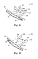
- FIG. 11 is a perspective view of another example locking mechanism for a lockable pushbutton.
- FIG. 13 is a top view of a housing having an example locking mechanism and pushbutton receiving area for a lockable pushbutton.
- FIG. 14 is an interior perspective view of an example housing showing a locking mechanism receiving area.
- FIG. 15 is a top perspective view of an example pushbutton.
- FIG. 16 is a bottom perspective view of an example pushbutton.
- FIG. 17 is an interior perspective view of a housing showing example locking mechanism inserted into receiving area in an unlocking orientation.
- FIG. 19 is a side section view of an example housing showing a locking mechanism inserted into receiving area in an unlocking orientation.
- FIG. 20 is a side section view showing a lockable pushbutton in an actuated position.
- FIG. 21 is an interior front view of a housing showing example locking mechanism inserted into receiving area in a locking orientation.
- FIG. 22 is a side section view of an example housing showing a locking mechanism inserted into receiving area in a locking orientation.
- FIG. 1 is a front perspective view of an example hand soap dispenser 100 having a lockable pushbutton 150 .
- Example dispenser 100 includes a housing 110 having a front cover 102 and a back plate 104 .
- Back plate 104 facilitates mounting of dispenser 100 to a wall or other object.
- housing 110 includes a hinge or hinges 112 which permit cover 102 to pivot between a closed position and an open position.
- Hand soap dispensers such as example dispenser 100
- various fluids may be dispensed using a manual or automatic dispenser.
- the fluid to be dispensed may include, for example, one or more of a hand soap, a lotion, a sanitizer, a disinfectant, or any type of cleaning agent.
- the fluid to be dispensed may also include one or more of a detergent, a bleach, or other type of laundry product.
- the lockable pushbutton(s) described herein may be used in any application in which a lockable pushbutton may be desired, and the disclosure is not limited in this respect.
- Example dispenser 100 is provided with a lockable pushbutton 150 .
- Lockable pushbutton 150 includes a locking mechanism (not shown in FIG. 1 ) configurable to provide lockable pushbutton 150 with two positions: a locked position and an unlocked position. In the unlocked position, actuation of lockable pushbutton 150 depresses a cover latch within the housing, thus permitting opening of cover 102 . In this way, the soap supply within the dispenser housing 110 may be changed or refilled as desired. In the locked position, actuation of lockable pushbutton 150 is prevented, thus preventing depression of the latch and therefore preventing opening of the housing.
- housing 110 further includes a keyhole 106 . To open cover 102 when lockable pushbutton 150 is in the locked position, a key (not shown in FIG. 1 ) may be inserted into keyhole 106 to deflect the cover latch and permit dispenser 100 to be opened.
- FIG. 2 is a top view of an example hand soap dispenser 100 showing an example implementation of a locking mechanism for a lockable pushbutton in an unlocked position.
- FIG. 3 is a top view of an example hand soap dispenser 100 showing an example implementation of a locking mechanism for a lockable pushbutton in a locked position.
- the pushbutton itself is not shown in FIGS. 2 and 3 .
- Housing 110 of dispenser 100 includes, as discussed above, a cover 102 and a back plate 104 .
- a catch 168 in combination with a latch on cover 102 , holds cover in a closed position with respect to back plate 104 .
- Housing 110 further includes a pushbutton receiving area 170 having sidewalls 151 and a base 152 .
- Base 152 includes an aperture 154 and a slot 156 .
- Slot 156 includes a detent 158 A at a first end and a detent 158 B at a second end.
- a locking stop 160 includes a stop body 161 having a first interlock post 162 A at a first end and a second interlock post 162 B at a second end.
- First interlock post 162 A fits into an interlock aperture 166 in base 152 .
- Second interlock post 162 B fits into slot 156 .
- locking stop 160 may rotate between the unlocked position shown in FIG. 2 and the locked position shown in FIG. 3 .
- stop body 161 When in the locked position (detent 158 B) shown in FIG. 2 , stop body 161 is positioned under base 152 and in a location that does not block aperture 154 .
- stop body 161 is positioned below aperture 154 in a location that blocks aperture 154 and provides the locking feature for lockable pushbutton 150 as will be described further below.
- first and second interlock posts 162 A and 162 B are flexible so that they may be fit into interlock aperture 166 , and slot 156 .
- the flexible interlock posts 162 B permits locking body 160 to rotate between the unlocked and locked positions (e.g., detents 158 A and 158 B, respectively) and provide positive feedback to the user that the stop is correctly placed in either the locked or the unlocked position.
- the lockable pushbutton shown in FIGS. 2 and 3 may be locked or unlocked without the need to add or remove any internal or external parts. This helps to reduce the complexity of the lockable pushbutton and may reduce the risk of losing loose separate components.
- this example of a lockable pushbutton is intuitive to use, in that locking stop 160 may be rotated to either lock or unlock the dispenser.
- the flexible interlock posts 162 A and 162 B and detents 158 A and 158 B may also help to reduce the likelihood that the dispenser may be accidently locked or unlocked.
- the lockable pushbutton design shown in FIGS. 2 and 3 has a minimal footprint, and therefore has a minimal, if any, influence on the overall size and shape of dispenser 100 .
- FIG. 4 is a perspective view showing an example implementation for the locking stop 160 shown in FIGS. 2 and 3 .
- locking stop 160 includes stop body 161 and interlock posts 162 A and 162 B.
- interlock posts 162 A and 162 B are made flexible by inclusion of flexibility slots 165 A and 165 B, respective. Slots 165 A and 165 B permit interlock posts 162 A and 162 B to flex inwardly and outwardly during insertion into interlock aperture 166 and slot 156 , and into detents 158 A and 158 B.
- interlock posts 162 A and 162 B include slots, other mechanisms for providing flexible interlock posts may also be used, and the disclosure is not limited in this respect.
- interlock posts 162 A and/or 162 B may be fabricated using a flexible material rather than or in addition to having slots.
- interlock posts may be made flexible in any of a number of ways, and that the disclosure is not limited in this respect.
- the interlock aperture 166 and/or slot 156 may alternatively or in addition to, be made flexible so as to provide one or more of the features described herein.
- FIG. 5 is a side section view of an example hand soap dispenser 100 showing a stop of a lockable pushbutton in an unlocked position.
- pushbutton 180 includes a tab portion 182 configured to fit within aperture 154 .
- a spring 184 permits pushbutton 180 to be depressed downwardly from its resting, topmost position. Spring 184 also returns pushbutton 180 to its resting topmost position when the downward pressure is released.
- stop body 161 is rotated to an unlocked position in which stop body 161 does not block aperture 182 . This permits pushbutton 180 to be depressed such that tab portion 182 extends through aperture 154 and further permitting an actuator portion 186 of pushbutton 180 to depresses latch 167 , releasing catch 168 and thus allowing front cover 102 to be opened.
- FIG. 6 is a side section view of an example hand soap dispenser 100 showing a stop of a lockable pushbutton in a locked position.
- stop body 161 is rotated to a locked position in which stop body 161 blocks aperture 154 .
- attempted actuation of pushbutton 180 is prevented, thus preventing opening of front cover 102 .
- FIG. 6 also shows a key 190 inserted into keyhole 106 . Depression of key in the direction indicated by arrow 191 depresses latch 167 , releasing catch 168 and permitting front cover 102 to be opened when lockable pushbutton is in the locked position.
- FIGS. 7 and 8 are bottom perspective views of a lockable pushbutton having a stop in an unlocked position.
- slot 156 is visible and stop body 161 can be seen in an unlocked position such that stop body 161 does not block aperture 154 .
- FIG. 7 shows pushbutton 180 in its resting topmost position.
- FIG. 8 shows that pushbutton 180 is being depressed in the direction indicated by arrows 181 , such that tab portion 182 extends through aperture 154 . Depression of pushbutton 180 in this manner further permit actuator portion 186 of pushbutton 180 to depress a latch (not shown in FIGS. 7-9 ), releasing catch 168 and allowing front cover 102 to be opened.
- FIG. 9 is a bottom perspective view of a lockable pushbutton having a stop in a locked position.
- stop body 161 is rotated in slot 156 to a locked position in which stop body 161 blocks aperture 154 .
- the stop body 161 prevents tab portion 182 from being depressed and extended through aperture 154 . Since the pushbutton may not be depressed, this further prevents actuator portion 186 from depressing the latch (not shown). Thus, attempted actuation of pushbutton 180 is prevented, thus preventing opening of front cover 102 .
- FIG. 10 is a back perspective view of an example hand soap dispenser 100 having a lockable pushbutton with a key 190 being inserted in a keyhole 106 to unlock the cover 102 .
- FIG. 11 is a perspective view of another example locking mechanism 202 for a lockable pushbutton.
- FIG. 12 is another perspective view of the example locking mechanism 202 .
- locking mechanism 202 is implemented as a one-piece article.
- Locking mechanism 202 is configured to be inserted into a corresponding locking mechanism receiving area (see, e.g., FIGS. 13 and 14 ) for a lockable pushbutton.
- Example locking mechanism 202 includes a base portion 201 having a front side 203 and a back side 207 .
- Two spaced apart locking projections 206 A and 206 B extend outwardly from back side 234 .
- Each locking projection 206 A and 206 B includes a locking post 204 A and 204 B, respectively.
- Locking mechanism 202 further includes two spaced apart unlocking projections 208 A (not visible in FIG. 11 ) and 208 B that also extend outwardly from back side 234 of base portion 201 .
- Unlocking projections 208 A and 208 B are substantially parallel with locking projections 206 A and 206 B such that projections 208 A- 208 B and 206 A- 206 B define a receiving space 209 , the purpose of which is to help fit the locking mechanism into the receiving area as described below with respect to FIGS. 17-22 .
- Locking mechanism 202 is configured to be insertable in two different orientations into the corresponding locking mechanism receiving area; a lock orientation and an unlock orientation. For example, to place the dispenser in a locked configuration, locking mechanism 202 may be inserted into the receiving area in an orientation in which the locking projections 206 A and 206 B are orientated toward the lockable pushbutton of the dispenser. That is, in this example, locking mechanism 202 would be inserted into the locking mechanism receiving area in the orientation shown in FIG. 11 , with the locking posts 204 A and 204 B facing a generally upward direction, and with unlocking projections 208 A and 208 B facing a generally downward direction.
- locking mechanism 202 may be inserted into the receiving area in an orientation in which the unlocking projections 208 A and 208 B are orientated toward the lockable pushbutton of the dispenser. That is, in this example, locking mechanism 202 would be inserted into the locking mechanism receiving area in the orientation shown in FIG. 12 , with unlocking projections 208 A and 208 B facing a generally upward direction, and with locking projections 206 A and 206 B and corresponding locking posts 204 A and 204 B, respectively, facing a generally downward direction.
- example locking mechanism 202 provides a one piece design that is reversible to provide both locking and unlocking functions for a lockable pushbutton.
- a first orientation such as that shown in FIG. 11
- locking mechanism may be inserted into the dispenser to provide a locking feature. If a user desires to change the dispenser from a locked configuration to an unlocked configuration, or vice versa, the user need only remove the locking mechanism 202 from the receiving area inside of the dispenser, rotate it 180°, and reinsert it in the reverse orientation (such as that shown in FIG. 12 ) to provide the opposite (unlocking in this example) function.
- the one piece design may help to reduce complexity and the risk of losing loose separate components.
- the design of example locking mechanism 202 is of a size and shape that would not significantly affect the size or shape of the dispenser housing.
- FIG. 13 is a top view of an example housing 210 having a locking mechanism and pushbutton receiving area 230 for a lockable pushbutton.
- Housing 210 may correspond with, for example, a hand soap dispenser, or other application in which a lockable pushbutton is desired.
- Housing 210 further includes a keyhole 242 into which a key may be inserted to unlock the housing when the lockable pushbutton (not shown in FIGS. 13 and 14 ) is in the locked position.
- Receiving area 230 further includes a base 218 having a spring receiving recess 214 .
- FIG. 14 is an interior perspective view of an example housing 210 , showing locking mechanism receiving area 230 .
- receiving area 230 includes base 218 and spring receiving recess 214 .
- a catch 244 permits a front cover (not shown in FIG. 14 ) to be opened and closed as described herein.
- Receiving area 230 further includes orientation indicators 240 A and 240 B.
- Orientation indicators 240 A and 240 B are configured to align with orientation aligner 205 on locking mechanism 202 . For example, when locking mechanism 202 is inserted into receiving area 230 in a locking orientation, orientation aligner 205 on locking mechanism 202 will line up with orientation indicator 240 B, thus indicating to a user that locking mechanism has been inserted in a locking orientation. Alternatively, when locking mechanism 202 is inserted into receiving area 230 in an unlocking orientation, orientation aligner 205 on locking mechanism 202 will line up with orientation indicator 240 A, thus indicating to a user that locking mechanism has been inserted in an unlocking orientation.
- FIG. 15 is a top perspective view of an example pushbutton 250 for use with example locking mechanism 202 .
- FIG. 16 is a bottom perspective view of example pushbutton 250 .
- Pushbutton 250 includes a top surface 251 and a bottom surface 253 .
- a user actuates pushbutton 250 by depressing top surface 251 of pushbutton 250 .
- Bottom surface 253 of pushbutton 250 includes various features which cooperate with locking mechanism 202 to provide the locking and unlocking features for a lockable pushbutton.
- bottom surface 253 includes downwardly extending projections 254 A and 254 B configured to align with locking posts 204 A and 204 B, respectively, of locking mechanism 202 .
- Bottom surface 253 may further include a spring guide 255 and tabs 252 A and 252 B that help fit pushbutton 250 into receiving area 230 .
- Bottom surface 253 further includes an actuating surface 258 such that when pushbutton 250 is actuated, actuating surface 253 depresses a latch within housing 210 (not shown in FIGS. 16-18 ) releasing catch 244 permitting housing 210 to be opened.
- FIG. 17 is an interior perspective view of a housing 210 , showing example locking mechanism 202 inserted into receiving area 230 in an unlocking orientation.
- Orientation aligner 205 is aligned with orientation indicator 240 A, indicating that locking mechanism 202 has been inserted in an unlocking configuration.
- unlocking projections 208 A and 208 B are orientated toward pushbutton 250
- locking projections 206 A and 206 B and corresponding locking posts 204 A and 204 B, respectively, are oriented away from pushbutton 250 .
- FIG. 18 is an interior front view of a housing 210 , showing example locking mechanism 202 inserted into receiving area 230 in an unlocking orientation.
- FIG. 18 shows downwardly extending projections 254 A and 254 B on bottom surface 253 of pushbutton 250 have enough space beneath them so that pushbutton 250 may be depressed.
- FIG. 19 is a side section view of an example housing 210 showing a locking mechanism 202 inserted into receiving area 230 in an unlocking orientation.
- FIG. 19 shows downwardly extending projections 254 A and 254 B on bottom surface 253 of pushbutton 250 have enough space beneath them so that pushbutton 250 may be depressed, as is shown in FIG. 20 .
- actuation surface 253 of pushbutton 250 depresses a latch 211 within housing 210 , releasing catch 244 , and allowing housing 210 to be opened.
- FIG. 21 is an interior front view of a housing 210 , showing example locking mechanism 202 inserted into receiving area 230 in a locking orientation.
- Orientation aligner 205 is aligned with orientation indicator 240 B, indicating that locking mechanism 202 has been inserted in a locking orientation.
- locking posts 204 A and 204 B are positioned toward pushbutton 250 such that locking posts 204 A and 204 B align with downwardly extending projections 254 A and 254 B, respectively, of bottom surface 253 of pushbutton 250 .
- locking posts 204 A and 204 B prevent actuation of pushbutton 250 , thus providing the locking feature for a lockable pushbutton.
- FIG. 22 is a side section view of an example housing 210 showing a locking mechanism 202 inserted into receiving area 230 in a locking orientation.
- locking posts 204 A and 204 B are positioned toward pushbutton 250 such that locking posts 204 A and 204 B align with downwardly extending projections 254 A and 254 B, respectively, of bottom surface 253 of pushbutton 250 .
- Locking posts 204 A and 204 B are thus in a position to prevent actuation of pushbutton 250 , thus providing the locking feature for a lockable pushbutton.
- a key may be inserted into a keyhole 242 (see, e.g., FIGS. 13 and 14 ) to unlock the housing when the reversible locking mechanism 202 is in the locked orientation, similarly to that described above with respect to FIGS. 6 and 10 .
- lockable pushbutton locking mechanisms for a lockable pushbutton
- locking mechanisms for a lockable pushbutton
- other variations of lockable pushbuttons and locking mechanisms may also be used without departing from the spirit and scope of the present disclosure.
- lockable pushbutton and locking mechanisms are described herein with respect to a hand soap dispenser, it shall further be understood that the lockable pushbutton and locking mechanisms such as those described herein may also be used in other applications in which a lockable pushbutton may be desired.
- Those of skill in the art will readily appreciate that many alternative designs may be used, and that the disclosure is not limited in this respect.
Abstract
Description
Claims (8)
Priority Applications (2)
| Application Number | Priority Date | Filing Date | Title |
|---|---|---|---|
| US13/868,645 US9340337B2 (en) | 2012-05-01 | 2013-04-23 | Dispenser with lockable pushbutton |
| PCT/US2013/038827 WO2013165994A1 (en) | 2012-05-01 | 2013-04-30 | Dispenser with lockable pushbutton |
Applications Claiming Priority (2)
| Application Number | Priority Date | Filing Date | Title |
|---|---|---|---|
| US201261640890P | 2012-05-01 | 2012-05-01 | |
| US13/868,645 US9340337B2 (en) | 2012-05-01 | 2013-04-23 | Dispenser with lockable pushbutton |
Publications (2)
| Publication Number | Publication Date |
|---|---|
| US20130292417A1 US20130292417A1 (en) | 2013-11-07 |
| US9340337B2 true US9340337B2 (en) | 2016-05-17 |
Family
ID=49511769
Family Applications (1)
| Application Number | Title | Priority Date | Filing Date |
|---|---|---|---|
| US13/868,645 Active 2033-10-30 US9340337B2 (en) | 2012-05-01 | 2013-04-23 | Dispenser with lockable pushbutton |
Country Status (2)
| Country | Link |
|---|---|
| US (1) | US9340337B2 (en) |
| WO (1) | WO2013165994A1 (en) |
Cited By (6)
| Publication number | Priority date | Publication date | Assignee | Title |
|---|---|---|---|---|
| US20170251884A1 (en) * | 2016-03-04 | 2017-09-07 | Georgia-Pacific Consumer Products Lp | Dispenser with stroke adjustment capabilities |
| US9999326B2 (en) | 2016-04-11 | 2018-06-19 | Gpcp Ip Holdings Llc | Sheet product dispenser |
| US10561282B2 (en) | 2017-12-21 | 2020-02-18 | Speakman Company | Ligature-resistant dispenser |
| US11412900B2 (en) | 2016-04-11 | 2022-08-16 | Gpcp Ip Holdings Llc | Sheet product dispenser with motor operation sensing |
| US11744413B2 (en) | 2021-10-07 | 2023-09-05 | Deb Ip Limited | Dispenser assembly |
| US11744412B2 (en) | 2021-10-07 | 2023-09-05 | Deb Ip Limited | Dispenser system |
Families Citing this family (9)
| Publication number | Priority date | Publication date | Assignee | Title |
|---|---|---|---|---|
| US8991655B2 (en) | 2013-02-15 | 2015-03-31 | Ecolab Usa Inc. | Fluid dispensers with increased mechanical advantage |
| US10743720B2 (en) | 2013-11-27 | 2020-08-18 | Archer Manufacturing, Inc. | Tamper-resistant devices and systems for wall-mounted dispensers |
| US10743721B2 (en) | 2013-11-27 | 2020-08-18 | Archer Manufacturing, Inc. | Tamper-resistant devices and systems for wall-mounted dispensers |
| US10123661B2 (en) * | 2013-11-27 | 2018-11-13 | Archer Manufacturing, Inc. | Tamper-proof and ligation resistant dispenser for liquids |
| US20150235549A1 (en) * | 2014-02-20 | 2015-08-20 | Debmed Usa Llc | Electronically monitored and portable point-of-care hand hygiene dispenser having security features |
| US10750911B2 (en) * | 2018-11-12 | 2020-08-25 | Op-Hygiene Ip Gmbh | Spring mechanism for fluid dispenser |
| GB2583364B (en) * | 2019-04-25 | 2022-02-09 | Brightwell Dispensers Ltd | A dispenser comprising a fastening mechanism having locked and unlocked states |
| US11724221B2 (en) * | 2021-03-18 | 2023-08-15 | Global Industrial Distribution Inc. | Filter key for fountain access door |
| WO2023083451A1 (en) * | 2021-11-11 | 2023-05-19 | Essity Hygiene And Health Aktiebolag | Electronic lock assembly for dispenser, and assembly method |
Citations (102)
| Publication number | Priority date | Publication date | Assignee | Title |
|---|---|---|---|---|
| US2898009A (en) | 1955-08-12 | 1959-08-04 | Newton Chambers & Co | Apparatus for dispensing pastes, creams and liquids |
| US3458090A (en) | 1967-12-01 | 1969-07-29 | Cook Chem Co | Fluid dispenser with adjustable stroke pump piston |
| US3971237A (en) * | 1975-07-09 | 1976-07-27 | Georgia-Pacific Corporation | Door lock |
| US4036406A (en) | 1974-06-03 | 1977-07-19 | Georgia-Pacific Corporation | Dispenser for liquids |
| US4084729A (en) | 1975-08-28 | 1978-04-18 | Maryland Cup Corporation | Dispensing valve |
| EP0176135A2 (en) | 1984-09-24 | 1986-04-02 | The Procter & Gamble Company | Liquid soap dispenser with improved pumping mechanism |
| US4621749A (en) | 1984-02-21 | 1986-11-11 | Go-Jo Industries | Dispensing apparatus |
| US4673109A (en) | 1985-10-18 | 1987-06-16 | Steiner Company, Inc. | Liquid soap dispensing system |
| US4921150A (en) | 1988-08-26 | 1990-05-01 | Pandel Instruments, Inc. | Automatic dispensing apparatus having low power consumption |
| US4978036A (en) | 1988-11-15 | 1990-12-18 | Koller Enterprises, Inc. | Dispensing valve |
| US5033657A (en) | 1990-06-27 | 1991-07-23 | James River Corporation | Adjustable stroke pump dispenser |
| US5156293A (en) | 1991-03-12 | 1992-10-20 | James River Ii, Inc. | Folded sheet product dispenser system |
| WO1994020407A1 (en) | 1993-03-01 | 1994-09-15 | Fresh Products, Inc. | Dual soap and fragrance dispenser |
| US5373970A (en) | 1993-10-29 | 1994-12-20 | Hygiene-Technik Inc. | Liquid soap dispenser for simplified replacement of soap reservoir |
| US5377871A (en) | 1993-01-04 | 1995-01-03 | Marlingford Holdings Limited | Dispenser having roller for dispensing fluid from a collapsible bag |
| US5443236A (en) | 1992-09-08 | 1995-08-22 | Gojo Industries, Inc. | Dispensing apparatus |
| US5445288A (en) | 1994-04-05 | 1995-08-29 | Sprintvest Corporation Nv | Liquid dispenser for dispensing foam |
| US5492247A (en) | 1994-06-02 | 1996-02-20 | Shu; Aling | Automatic soap dispenser |
| US5836482A (en) | 1997-04-04 | 1998-11-17 | Ophardt; Hermann | Automated fluid dispenser |
| US5992698A (en) | 1995-08-07 | 1999-11-30 | Ecolab Inc. | Liquid soap dispenser |
| JP2000023871A (en) | 1998-06-11 | 2000-01-25 | Ecolab Inc | Hand soap dispenser with usage related data collection and display capabilities |
| US6036056A (en) | 1997-05-05 | 2000-03-14 | Lee; Kuo-Chou | Automatic soap dispensing device |
| US6082586A (en) | 1998-03-30 | 2000-07-04 | Deb Ip Limited | Liquid dispenser for dispensing foam |
| US6189740B1 (en) | 1998-12-30 | 2001-02-20 | Steris Inc | Antiseptic soap dispenser with selectively variable dose |
| US6209752B1 (en) | 1999-03-10 | 2001-04-03 | Kimberly-Clark Worldwide, Inc. | Automatic soap dispenser |
| US6347724B1 (en) | 2000-11-01 | 2002-02-19 | Ultraclenz Engineering Group | Automatic dispenser apparatus |
| US20020074356A1 (en) | 2000-12-19 | 2002-06-20 | Kimberly-Clark Worldwide, Inc. | Self-contained viscous liquid dispenser |
| WO2002049490A1 (en) | 2000-12-19 | 2002-06-27 | Kimberly-Clark Worldwide, Inc. | Self-contained viscous liquid dispenser |
| US6516976B2 (en) | 2000-12-19 | 2003-02-11 | Kimberly-Clark Worldwide, Inc. | Dosing pump for liquid dispensers |
| US20030141318A1 (en) | 2000-08-08 | 2003-07-31 | Sorensen Henrik Bonnelycke | Soap dispenser |
| US6607103B2 (en) | 2001-10-12 | 2003-08-19 | Gerenraich Family Trust | Touch free dispenser |
| US6619512B1 (en) | 2002-07-16 | 2003-09-16 | Joseph S. Kanfer | Lock-out mechanism for dispenser |
| US6701573B1 (en) | 2002-07-23 | 2004-03-09 | Joseph S. Kanfer | Fast assembly hinge |
| US6772328B1 (en) | 1999-06-18 | 2004-08-03 | Samsung Electronics Co., Ltd. | Dynamic initialization of processor module via motherboard interface |
| EP1454576A2 (en) | 2003-03-05 | 2004-09-08 | Brightwell Dispensers Limited | Soap dispensing device |
| WO2004086731A2 (en) | 2003-03-21 | 2004-10-07 | Kanfer, Joseph | Apparatus for hands-free dispensing of a measured quantity of material |
| US20040232168A1 (en) * | 2002-07-25 | 2004-11-25 | Joseph Kanfer | Wall-mounted dispenser assembly with transparent window |
| US20050064281A1 (en) | 2002-01-18 | 2005-03-24 | Heiner Ophardt | Combination liquid dispenser and electrochemical cell |
| US20050072808A1 (en) | 2001-11-30 | 2005-04-07 | Sachiko Kitamura | Pump with function of measuring fixed amount |
| US6877642B1 (en) | 2000-01-04 | 2005-04-12 | Joseph S. Kanfer | Wall-mounted dispenser for liquids |
| US20050263545A1 (en) | 2004-05-26 | 2005-12-01 | Heiner Ophardt | Time delay soap dispenser |
| US20050284888A1 (en) * | 2004-06-28 | 2005-12-29 | Rhodenbaugh Joseph W | Refillable product dispenser and system |
| US20060032871A1 (en) | 2004-08-12 | 2006-02-16 | Heiner Ophardt | Cantilevered spring |
| US20060041197A1 (en) | 2004-08-19 | 2006-02-23 | Heiner Ophardt | Dispenser with sensor |
| US7028861B2 (en) * | 2003-12-16 | 2006-04-18 | Joseph S. Kanfer | Electronically keyed dispensing systems and related methods of installation and use |
| US7044328B1 (en) | 2002-07-08 | 2006-05-16 | Joseph S. Kanfer | Tamper proof latch for dispensers |
| US7066356B2 (en) | 2002-08-15 | 2006-06-27 | Ecolab Inc. | Foam soap dispenser for push operation |
| US7084592B2 (en) | 2004-10-12 | 2006-08-01 | Rodrian James A | Method and apparatus for controlling a DC motor by counting current pulses |
| US20060175353A1 (en) | 2005-02-09 | 2006-08-10 | Heiner Ophardt | Dispenser with side mounted activation levers |
| US20060213929A1 (en) * | 2005-02-09 | 2006-09-28 | Heiner Ophardt | Fluid dispenser lock defeater |
| US20070000941A1 (en) | 2005-07-01 | 2007-01-04 | Hadden David M | Motion-activated soap dispenser |
| US20070158359A1 (en) | 2005-12-08 | 2007-07-12 | Rodrian James A | Method and Apparatus for Controlling a Dispenser and Detecting a User |
| US20070169576A1 (en) | 2006-01-25 | 2007-07-26 | Hermann Ophardt | Lever with shifting fulcrum point |
| US7278554B2 (en) | 2004-05-10 | 2007-10-09 | Chester Labs, Inc. | Hinged dispenser housing and adaptor |
| US20070257058A1 (en) | 2006-05-02 | 2007-11-08 | Heiner Ophardt | Wall plate system with releasable lock |
| US7296765B2 (en) | 2004-11-29 | 2007-11-20 | Alwin Manufacturing Co., Inc. | Automatic dispensers |
| WO2008006209A2 (en) | 2006-07-14 | 2008-01-17 | Deb Ip Limited | Universal mounting system |
| EP1280448B1 (en) | 2000-05-04 | 2008-02-27 | Kimberly-Clark Worldwide, Inc. | Wipes dispensing system |
| US20080121659A1 (en) | 2006-11-29 | 2008-05-29 | Heiner Ophardt | Arcuate to linear motion translation assembly |
| US20080185399A1 (en) | 2007-02-01 | 2008-08-07 | Simplehuman, Llc | Electric soap dispenser |
| US20080283556A1 (en) | 2007-05-16 | 2008-11-20 | David Snodgrass | Keyed dispensing cartridge system |
| EP2005871A2 (en) | 2007-06-22 | 2008-12-24 | Gotohti.com Inc. | Split engagement flange for soap dispenser pump piston |
| US20090045221A1 (en) | 2007-06-18 | 2009-02-19 | Heiner Ophardt | Touchless optically controlled dispenser |
| US7497103B1 (en) * | 2006-04-22 | 2009-03-03 | The Eastern Company | Dual-acting latch and strike |
| US20090101671A1 (en) | 2007-10-22 | 2009-04-23 | Georgia-Pacific Consumer Products Lp | Pumping dispenser |
| US20090120950A1 (en) | 2007-11-13 | 2009-05-14 | Richard Petras Titas | Center-pull paper towel dispenser |
| US7540397B2 (en) | 2004-05-10 | 2009-06-02 | Technical Concepts, Llc | Apparatus and method for dispensing post-foaming gel soap |
| US20090184137A1 (en) | 2006-04-26 | 2009-07-23 | O'brien Michael | Dispenser with Actuating Means Unengaged with the Dispensing Means |
| US20090204256A1 (en) | 2007-11-14 | 2009-08-13 | Gojo Industries, Inc. | Method and device for indicating future need for product replacement of random-use dispensing |
| US20090266842A1 (en) | 2008-04-25 | 2009-10-29 | Snodgrass David L | Manual and touch-free convertible fluid dispenser |
| US20090302061A1 (en) | 2008-06-05 | 2009-12-10 | Heiner Ophardt | Spring force adjustment system |
| US20090302067A1 (en) | 2005-10-10 | 2009-12-10 | Bart Relinda Jan Hendrickx | Device for metered dispensing of pasty mass, and a container therefor |
| US20090308887A1 (en) | 2008-06-13 | 2009-12-17 | American Sterilizer Company | Fluid dispenser |
| US7637391B2 (en) | 2006-09-01 | 2009-12-29 | Joseph S Kanfer | Cover release mechanism for a dispenser |
| US20100012679A1 (en) | 2008-07-15 | 2010-01-21 | Georgia-Pacific Consumer Products Lp | Dispensers For Dispensing a Flowable Product and Methods For Controlling the Dispensers |
| US20100059550A1 (en) | 2008-09-11 | 2010-03-11 | Ciavarella Nick E | Pump having a flexible mechanism for engagement with a dispenser |
| US20100072227A1 (en) * | 2008-09-25 | 2010-03-25 | Georgia-Pacific Consumer Products Lp | Interchangeable access device for a dispenser |
| US20100140297A1 (en) | 2008-12-08 | 2010-06-10 | Heiner Ophardt | Engagement flange for fluid dispenser pump piston |
| US20100147890A1 (en) | 2008-12-16 | 2010-06-17 | Ciavarella Nick E | Manual skin-care product dispenser |
| US20100163580A1 (en) | 2008-12-08 | 2010-07-01 | Heiner Ophardt | Engagement flange for removable dispenser cartridge |
| US20100206909A1 (en) | 2007-09-21 | 2010-08-19 | O'brien Michael | Dispenser mechanism |
| EP2223642A2 (en) | 2009-02-27 | 2010-09-01 | Gotohti.com Inc. | Manual fluid dispenser with electrical generator |
| US7798370B2 (en) | 2003-10-25 | 2010-09-21 | Gojo Industries, Inc. | Universal collar key |
| US20100237096A1 (en) | 2009-03-17 | 2010-09-23 | Gojo Industries, Inc. | Wirelessly-powered dispenser system |
| US20100252568A1 (en) | 2009-04-02 | 2010-10-07 | Gojo Industries, Inc. | Locking dispenser |
| US20100288788A1 (en) | 2009-02-27 | 2010-11-18 | Heiner Ophardt | Manual fluid dispenser with discharge measurement |
| US20100308076A1 (en) | 2009-06-08 | 2010-12-09 | Snodgrass David L | Touch-Free Pressurized Can Dispenser |
| US20100320227A1 (en) | 2009-06-19 | 2010-12-23 | Gojo Industries, Inc. | Dispenser with discrete dispense cycles |
| US20110011890A1 (en) | 2009-07-20 | 2011-01-20 | Gojo Industries, Inc. | Dispenser housing with locking mechanism |
| US20110017778A1 (en) | 2007-01-30 | 2011-01-27 | Fedor Kadiks | Automatic Dispenser |
| US7896196B2 (en) | 2007-06-27 | 2011-03-01 | Joseph S. Kanfer | Fluid dispenser having infrared user sensor |
| US20110056987A1 (en) * | 2009-08-12 | 2011-03-10 | Proper Scott T | Dispenser with lockout device |
| US20110062182A1 (en) | 2009-09-17 | 2011-03-17 | Gojo Industries, Inc. | Dispenser with an automatic pump output detection system |
| US20110101032A1 (en) | 2009-10-29 | 2011-05-05 | Hokwang Industries Co., Ltd. | Pressing structure of soap dispenser capable of adjusting output soap amount |
| WO2011077111A1 (en) | 2009-12-22 | 2011-06-30 | Bryan Gary Houghton | Bait dispenser |
| US7980777B2 (en) | 2007-01-09 | 2011-07-19 | The Clorox Company | Fluid dispensing system with separate pump actuator and dispensing pad |
| US7992804B2 (en) | 2005-02-14 | 2011-08-09 | Stockhausen Gmbh | Dispenser |
| US20120006848A1 (en) | 2010-07-07 | 2012-01-12 | Gojo Industries, Inc. | Dispenser with automatic pump output detection system |
| US20120080452A1 (en) | 2010-09-30 | 2012-04-05 | Rubbermaid Commercial Products, Llc | Dispenser with discharge quantity selector |
| US8251409B2 (en) * | 2008-06-26 | 2012-08-28 | Shenzhen Futaihong Precision Industry Co., Ltd. | Cover latching mechanism for electronic device |
| US8657160B2 (en) * | 2010-10-18 | 2014-02-25 | Better Science, Llc | Pump bottle adapter |
| US8851331B2 (en) * | 2012-05-04 | 2014-10-07 | Ecolab Usa Inc. | Fluid dispensers with adjustable dosing |
-
2013
- 2013-04-23 US US13/868,645 patent/US9340337B2/en active Active
- 2013-04-30 WO PCT/US2013/038827 patent/WO2013165994A1/en active Application Filing
Patent Citations (116)
| Publication number | Priority date | Publication date | Assignee | Title |
|---|---|---|---|---|
| US2898009A (en) | 1955-08-12 | 1959-08-04 | Newton Chambers & Co | Apparatus for dispensing pastes, creams and liquids |
| US3458090A (en) | 1967-12-01 | 1969-07-29 | Cook Chem Co | Fluid dispenser with adjustable stroke pump piston |
| US4036406A (en) | 1974-06-03 | 1977-07-19 | Georgia-Pacific Corporation | Dispenser for liquids |
| US3971237A (en) * | 1975-07-09 | 1976-07-27 | Georgia-Pacific Corporation | Door lock |
| US4084729A (en) | 1975-08-28 | 1978-04-18 | Maryland Cup Corporation | Dispensing valve |
| US4621749A (en) | 1984-02-21 | 1986-11-11 | Go-Jo Industries | Dispensing apparatus |
| EP0176135A2 (en) | 1984-09-24 | 1986-04-02 | The Procter & Gamble Company | Liquid soap dispenser with improved pumping mechanism |
| US4673109A (en) | 1985-10-18 | 1987-06-16 | Steiner Company, Inc. | Liquid soap dispensing system |
| US4921150A (en) | 1988-08-26 | 1990-05-01 | Pandel Instruments, Inc. | Automatic dispensing apparatus having low power consumption |
| US4978036A (en) | 1988-11-15 | 1990-12-18 | Koller Enterprises, Inc. | Dispensing valve |
| US5033657A (en) | 1990-06-27 | 1991-07-23 | James River Corporation | Adjustable stroke pump dispenser |
| US5156293A (en) | 1991-03-12 | 1992-10-20 | James River Ii, Inc. | Folded sheet product dispenser system |
| US5443236A (en) | 1992-09-08 | 1995-08-22 | Gojo Industries, Inc. | Dispensing apparatus |
| US5465877A (en) | 1992-09-08 | 1995-11-14 | Gojo Industries, Inc. | Adjustable stroke pump dispenser |
| US5377871A (en) | 1993-01-04 | 1995-01-03 | Marlingford Holdings Limited | Dispenser having roller for dispensing fluid from a collapsible bag |
| WO1994020407A1 (en) | 1993-03-01 | 1994-09-15 | Fresh Products, Inc. | Dual soap and fragrance dispenser |
| US5373970A (en) | 1993-10-29 | 1994-12-20 | Hygiene-Technik Inc. | Liquid soap dispenser for simplified replacement of soap reservoir |
| US5431309A (en) | 1993-10-29 | 1995-07-11 | Hygiene-Technik Inc. | Liquid soap dispenser for simplified replacement of soap reservoir |
| US5445288A (en) | 1994-04-05 | 1995-08-29 | Sprintvest Corporation Nv | Liquid dispenser for dispensing foam |
| US5492247A (en) | 1994-06-02 | 1996-02-20 | Shu; Aling | Automatic soap dispenser |
| US5992698A (en) | 1995-08-07 | 1999-11-30 | Ecolab Inc. | Liquid soap dispenser |
| US5836482A (en) | 1997-04-04 | 1998-11-17 | Ophardt; Hermann | Automated fluid dispenser |
| US6036056A (en) | 1997-05-05 | 2000-03-14 | Lee; Kuo-Chou | Automatic soap dispensing device |
| US6082586A (en) | 1998-03-30 | 2000-07-04 | Deb Ip Limited | Liquid dispenser for dispensing foam |
| JP2000023871A (en) | 1998-06-11 | 2000-01-25 | Ecolab Inc | Hand soap dispenser with usage related data collection and display capabilities |
| US6707873B2 (en) | 1998-06-11 | 2004-03-16 | Ecolab Inc. | Usage competent hand soap dispenser with data collection and display capabilities |
| US6189740B1 (en) | 1998-12-30 | 2001-02-20 | Steris Inc | Antiseptic soap dispenser with selectively variable dose |
| US6209752B1 (en) | 1999-03-10 | 2001-04-03 | Kimberly-Clark Worldwide, Inc. | Automatic soap dispenser |
| US6772328B1 (en) | 1999-06-18 | 2004-08-03 | Samsung Electronics Co., Ltd. | Dynamic initialization of processor module via motherboard interface |
| US6877642B1 (en) | 2000-01-04 | 2005-04-12 | Joseph S. Kanfer | Wall-mounted dispenser for liquids |
| EP1280448B1 (en) | 2000-05-04 | 2008-02-27 | Kimberly-Clark Worldwide, Inc. | Wipes dispensing system |
| US20030141318A1 (en) | 2000-08-08 | 2003-07-31 | Sorensen Henrik Bonnelycke | Soap dispenser |
| US6347724B1 (en) | 2000-11-01 | 2002-02-19 | Ultraclenz Engineering Group | Automatic dispenser apparatus |
| US6516976B2 (en) | 2000-12-19 | 2003-02-11 | Kimberly-Clark Worldwide, Inc. | Dosing pump for liquid dispensers |
| WO2002049490A1 (en) | 2000-12-19 | 2002-06-27 | Kimberly-Clark Worldwide, Inc. | Self-contained viscous liquid dispenser |
| US20020074356A1 (en) | 2000-12-19 | 2002-06-20 | Kimberly-Clark Worldwide, Inc. | Self-contained viscous liquid dispenser |
| US6607103B2 (en) | 2001-10-12 | 2003-08-19 | Gerenraich Family Trust | Touch free dispenser |
| US20050072808A1 (en) | 2001-11-30 | 2005-04-07 | Sachiko Kitamura | Pump with function of measuring fixed amount |
| US7530477B2 (en) | 2002-01-18 | 2009-05-12 | Gotohti.Com Inc. | Combination liquid dispenser and electrochemical cell |
| US20050064281A1 (en) | 2002-01-18 | 2005-03-24 | Heiner Ophardt | Combination liquid dispenser and electrochemical cell |
| US7044328B1 (en) | 2002-07-08 | 2006-05-16 | Joseph S. Kanfer | Tamper proof latch for dispensers |
| US6619512B1 (en) | 2002-07-16 | 2003-09-16 | Joseph S. Kanfer | Lock-out mechanism for dispenser |
| US6701573B1 (en) | 2002-07-23 | 2004-03-09 | Joseph S. Kanfer | Fast assembly hinge |
| US20040232168A1 (en) * | 2002-07-25 | 2004-11-25 | Joseph Kanfer | Wall-mounted dispenser assembly with transparent window |
| US7066356B2 (en) | 2002-08-15 | 2006-06-27 | Ecolab Inc. | Foam soap dispenser for push operation |
| EP1454576A2 (en) | 2003-03-05 | 2004-09-08 | Brightwell Dispensers Limited | Soap dispensing device |
| US7611030B2 (en) | 2003-03-21 | 2009-11-03 | Joseph S. Kanfer | Apparatus for hands-free dispensing of a measured quantity of material |
| US7909209B2 (en) | 2003-03-21 | 2011-03-22 | Joseph S. Kanfer | Apparatus for hands-free dispensing of a measured quantity of material |
| WO2004086731A2 (en) | 2003-03-21 | 2004-10-07 | Kanfer, Joseph | Apparatus for hands-free dispensing of a measured quantity of material |
| US7798370B2 (en) | 2003-10-25 | 2010-09-21 | Gojo Industries, Inc. | Universal collar key |
| US7028861B2 (en) * | 2003-12-16 | 2006-04-18 | Joseph S. Kanfer | Electronically keyed dispensing systems and related methods of installation and use |
| US7540397B2 (en) | 2004-05-10 | 2009-06-02 | Technical Concepts, Llc | Apparatus and method for dispensing post-foaming gel soap |
| US7278554B2 (en) | 2004-05-10 | 2007-10-09 | Chester Labs, Inc. | Hinged dispenser housing and adaptor |
| US20050263545A1 (en) | 2004-05-26 | 2005-12-01 | Heiner Ophardt | Time delay soap dispenser |
| US20050284888A1 (en) * | 2004-06-28 | 2005-12-29 | Rhodenbaugh Joseph W | Refillable product dispenser and system |
| US7748574B2 (en) | 2004-08-12 | 2010-07-06 | Gotohti.Com | Cantilevered spring |
| US7568598B2 (en) | 2004-08-12 | 2009-08-04 | Gotohti.Com Inc. | Cantilevered spring |
| US20060032871A1 (en) | 2004-08-12 | 2006-02-16 | Heiner Ophardt | Cantilevered spring |
| US7247140B2 (en) | 2004-08-19 | 2007-07-24 | Gotohti.Com Inc. | Dispenser with sensor |
| US20060041197A1 (en) | 2004-08-19 | 2006-02-23 | Heiner Ophardt | Dispenser with sensor |
| US7084592B2 (en) | 2004-10-12 | 2006-08-01 | Rodrian James A | Method and apparatus for controlling a DC motor by counting current pulses |
| US7296765B2 (en) | 2004-11-29 | 2007-11-20 | Alwin Manufacturing Co., Inc. | Automatic dispensers |
| US7232045B2 (en) | 2005-02-09 | 2007-06-19 | Hygiene-Technik Inc. | Fluid dispenser lock defeater |
| US7367477B2 (en) | 2005-02-09 | 2008-05-06 | Hygiene-Technik Inc. | Dispenser with side mounted activation levers |
| US20060213929A1 (en) * | 2005-02-09 | 2006-09-28 | Heiner Ophardt | Fluid dispenser lock defeater |
| US20060175353A1 (en) | 2005-02-09 | 2006-08-10 | Heiner Ophardt | Dispenser with side mounted activation levers |
| US7992804B2 (en) | 2005-02-14 | 2011-08-09 | Stockhausen Gmbh | Dispenser |
| US20070000941A1 (en) | 2005-07-01 | 2007-01-04 | Hadden David M | Motion-activated soap dispenser |
| US20090302067A1 (en) | 2005-10-10 | 2009-12-10 | Bart Relinda Jan Hendrickx | Device for metered dispensing of pasty mass, and a container therefor |
| US20070158359A1 (en) | 2005-12-08 | 2007-07-12 | Rodrian James A | Method and Apparatus for Controlling a Dispenser and Detecting a User |
| US20070169576A1 (en) | 2006-01-25 | 2007-07-26 | Hermann Ophardt | Lever with shifting fulcrum point |
| US7765916B2 (en) | 2006-01-25 | 2010-08-03 | Gotohti.Com Inc. | Lever with shifting fulcrum point |
| US7497103B1 (en) * | 2006-04-22 | 2009-03-03 | The Eastern Company | Dual-acting latch and strike |
| US20090184137A1 (en) | 2006-04-26 | 2009-07-23 | O'brien Michael | Dispenser with Actuating Means Unengaged with the Dispensing Means |
| US20070257058A1 (en) | 2006-05-02 | 2007-11-08 | Heiner Ophardt | Wall plate system with releasable lock |
| WO2008006209A2 (en) | 2006-07-14 | 2008-01-17 | Deb Ip Limited | Universal mounting system |
| US7637391B2 (en) | 2006-09-01 | 2009-12-29 | Joseph S Kanfer | Cover release mechanism for a dispenser |
| US7798371B2 (en) | 2006-11-29 | 2010-09-21 | Gotohti.Com Inc. | Arcuate to linear motion translation assembly |
| US20080121659A1 (en) | 2006-11-29 | 2008-05-29 | Heiner Ophardt | Arcuate to linear motion translation assembly |
| US7980777B2 (en) | 2007-01-09 | 2011-07-19 | The Clorox Company | Fluid dispensing system with separate pump actuator and dispensing pad |
| US20110017778A1 (en) | 2007-01-30 | 2011-01-27 | Fedor Kadiks | Automatic Dispenser |
| US20080185399A1 (en) | 2007-02-01 | 2008-08-07 | Simplehuman, Llc | Electric soap dispenser |
| US20080283556A1 (en) | 2007-05-16 | 2008-11-20 | David Snodgrass | Keyed dispensing cartridge system |
| US20090045221A1 (en) | 2007-06-18 | 2009-02-19 | Heiner Ophardt | Touchless optically controlled dispenser |
| EP2005871A2 (en) | 2007-06-22 | 2008-12-24 | Gotohti.com Inc. | Split engagement flange for soap dispenser pump piston |
| US7896196B2 (en) | 2007-06-27 | 2011-03-01 | Joseph S. Kanfer | Fluid dispenser having infrared user sensor |
| US20100206909A1 (en) | 2007-09-21 | 2010-08-19 | O'brien Michael | Dispenser mechanism |
| US20090101671A1 (en) | 2007-10-22 | 2009-04-23 | Georgia-Pacific Consumer Products Lp | Pumping dispenser |
| US20090120950A1 (en) | 2007-11-13 | 2009-05-14 | Richard Petras Titas | Center-pull paper towel dispenser |
| US20090204256A1 (en) | 2007-11-14 | 2009-08-13 | Gojo Industries, Inc. | Method and device for indicating future need for product replacement of random-use dispensing |
| US20090266842A1 (en) | 2008-04-25 | 2009-10-29 | Snodgrass David L | Manual and touch-free convertible fluid dispenser |
| US8245881B2 (en) | 2008-06-05 | 2012-08-21 | Gotohti.Com Inc | Spring force adjustment system |
| US20090302061A1 (en) | 2008-06-05 | 2009-12-10 | Heiner Ophardt | Spring force adjustment system |
| US20090308887A1 (en) | 2008-06-13 | 2009-12-17 | American Sterilizer Company | Fluid dispenser |
| US8251409B2 (en) * | 2008-06-26 | 2012-08-28 | Shenzhen Futaihong Precision Industry Co., Ltd. | Cover latching mechanism for electronic device |
| US20100012679A1 (en) | 2008-07-15 | 2010-01-21 | Georgia-Pacific Consumer Products Lp | Dispensers For Dispensing a Flowable Product and Methods For Controlling the Dispensers |
| US20100059550A1 (en) | 2008-09-11 | 2010-03-11 | Ciavarella Nick E | Pump having a flexible mechanism for engagement with a dispenser |
| US20100072227A1 (en) * | 2008-09-25 | 2010-03-25 | Georgia-Pacific Consumer Products Lp | Interchangeable access device for a dispenser |
| US20100163580A1 (en) | 2008-12-08 | 2010-07-01 | Heiner Ophardt | Engagement flange for removable dispenser cartridge |
| US20100140297A1 (en) | 2008-12-08 | 2010-06-10 | Heiner Ophardt | Engagement flange for fluid dispenser pump piston |
| US20100147890A1 (en) | 2008-12-16 | 2010-06-17 | Ciavarella Nick E | Manual skin-care product dispenser |
| US20100288788A1 (en) | 2009-02-27 | 2010-11-18 | Heiner Ophardt | Manual fluid dispenser with discharge measurement |
| EP2223642A2 (en) | 2009-02-27 | 2010-09-01 | Gotohti.com Inc. | Manual fluid dispenser with electrical generator |
| US20100237096A1 (en) | 2009-03-17 | 2010-09-23 | Gojo Industries, Inc. | Wirelessly-powered dispenser system |
| US20100252568A1 (en) | 2009-04-02 | 2010-10-07 | Gojo Industries, Inc. | Locking dispenser |
| US20100308076A1 (en) | 2009-06-08 | 2010-12-09 | Snodgrass David L | Touch-Free Pressurized Can Dispenser |
| US20100320227A1 (en) | 2009-06-19 | 2010-12-23 | Gojo Industries, Inc. | Dispenser with discrete dispense cycles |
| US20110011890A1 (en) | 2009-07-20 | 2011-01-20 | Gojo Industries, Inc. | Dispenser housing with locking mechanism |
| US20110056987A1 (en) * | 2009-08-12 | 2011-03-10 | Proper Scott T | Dispenser with lockout device |
| US20110062182A1 (en) | 2009-09-17 | 2011-03-17 | Gojo Industries, Inc. | Dispenser with an automatic pump output detection system |
| US20110101032A1 (en) | 2009-10-29 | 2011-05-05 | Hokwang Industries Co., Ltd. | Pressing structure of soap dispenser capable of adjusting output soap amount |
| WO2011077111A1 (en) | 2009-12-22 | 2011-06-30 | Bryan Gary Houghton | Bait dispenser |
| US20120006848A1 (en) | 2010-07-07 | 2012-01-12 | Gojo Industries, Inc. | Dispenser with automatic pump output detection system |
| US20120080452A1 (en) | 2010-09-30 | 2012-04-05 | Rubbermaid Commercial Products, Llc | Dispenser with discharge quantity selector |
| US8657160B2 (en) * | 2010-10-18 | 2014-02-25 | Better Science, Llc | Pump bottle adapter |
| US8851331B2 (en) * | 2012-05-04 | 2014-10-07 | Ecolab Usa Inc. | Fluid dispensers with adjustable dosing |
Non-Patent Citations (4)
| Title |
|---|
| International Search Report and Written Opinion of international application No. PCT/US2013/038827, dated Aug. 20, 20123, 13 pp. |
| U.S. Appl. No. 13/768,110, by John T. Pelkey, filed Feb. 15, 2013. |
| U.S. Appl. No. 13/769,155, by John T. Pelkey, filed Feb. 15, 2013. |
| U.S. Appl. No. 13/869,205, by John T. Pelkey, filed Apr. 24, 2013. |
Cited By (10)
| Publication number | Priority date | Publication date | Assignee | Title |
|---|---|---|---|---|
| US20170251884A1 (en) * | 2016-03-04 | 2017-09-07 | Georgia-Pacific Consumer Products Lp | Dispenser with stroke adjustment capabilities |
| US10034583B2 (en) * | 2016-03-04 | 2018-07-31 | Gpcp Ip Holdings Llc | Dispenser with stroke adjustment capabilities |
| US9999326B2 (en) | 2016-04-11 | 2018-06-19 | Gpcp Ip Holdings Llc | Sheet product dispenser |
| US10588469B2 (en) | 2016-04-11 | 2020-03-17 | Gpcp Ip Holdings Llc | Sheet product dispenser |
| US11395566B2 (en) | 2016-04-11 | 2022-07-26 | Gpcp Ip Holdings Llc | Sheet product dispenser |
| US11412900B2 (en) | 2016-04-11 | 2022-08-16 | Gpcp Ip Holdings Llc | Sheet product dispenser with motor operation sensing |
| US10561282B2 (en) | 2017-12-21 | 2020-02-18 | Speakman Company | Ligature-resistant dispenser |
| US11045052B2 (en) | 2017-12-21 | 2021-06-29 | Speakman Company | Ligature-resistant dispenser |
| US11744413B2 (en) | 2021-10-07 | 2023-09-05 | Deb Ip Limited | Dispenser assembly |
| US11744412B2 (en) | 2021-10-07 | 2023-09-05 | Deb Ip Limited | Dispenser system |
Also Published As
| Publication number | Publication date |
|---|---|
| US20130292417A1 (en) | 2013-11-07 |
| WO2013165994A1 (en) | 2013-11-07 |
Similar Documents
| Publication | Publication Date | Title |
|---|---|---|
| US9340337B2 (en) | Dispenser with lockable pushbutton | |
| US8561847B2 (en) | Dispenser housing with locking mechanism | |
| JP6243405B2 (en) | Fluid dispenser with adjustable dose | |
| AU2009232435B2 (en) | Lock | |
| US7588209B2 (en) | Multiple-roll toilet tissue holder and dispenser | |
| KR20140050063A (en) | Dispenser lockout mechanism | |
| JPS6238130A (en) | Anchor tool for bag shaped liquid distributor | |
| US7044328B1 (en) | Tamper proof latch for dispensers | |
| RU2764998C2 (en) | Receiving apparatus for a dosing container | |
| US20110303699A1 (en) | Interchangable access device for a dispenser | |
| WO2019081006A1 (en) | Apparatus for handle disinfection | |
| US9826867B2 (en) | Dual compartment mountable sanitation station | |
| JP5212999B1 (en) | Lock mechanism and disinfectant dispenser with lock mechanism | |
| CN114190686A (en) | Locking base for dispensers and the like | |
| PL244366B1 (en) | Wall-mounted soap dispenser | |
| ZA200802107B (en) | A locking mechanism for a housing |
Legal Events
| Date | Code | Title | Description |
|---|---|---|---|
| AS | Assignment |
Owner name: ECOLAB USA INC., MINNESOTA Free format text: ASSIGNMENT OF ASSIGNORS INTEREST;ASSIGNORS:PELKEY, JOHN T.;CARLSON, BRIAN P.;ANDERSON, TROY A.;AND OTHERS;SIGNING DATES FROM 20130731 TO 20130821;REEL/FRAME:031081/0839 |
|
| STCF | Information on status: patent grant |
Free format text: PATENTED CASE |
|
| MAFP | Maintenance fee payment |
Free format text: PAYMENT OF MAINTENANCE FEE, 4TH YEAR, LARGE ENTITY (ORIGINAL EVENT CODE: M1551); ENTITY STATUS OF PATENT OWNER: LARGE ENTITY Year of fee payment: 4 |
|
| MAFP | Maintenance fee payment |
Free format text: PAYMENT OF MAINTENANCE FEE, 8TH YEAR, LARGE ENTITY (ORIGINAL EVENT CODE: M1552); ENTITY STATUS OF PATENT OWNER: LARGE ENTITY Year of fee payment: 8 |