US9355446B2 - Image processing apparatus and image processing method - Google Patents

Image processing apparatus and image processing method Download PDF

Info

Publication number
US9355446B2
US9355446B2 US13/271,604 US201113271604A US9355446B2 US 9355446 B2 US9355446 B2 US 9355446B2 US 201113271604 A US201113271604 A US 201113271604A US 9355446 B2 US9355446 B2 US 9355446B2
Authority
US
United States
Prior art keywords
morbid
portions
primary
morbid portions
layer
Prior art date
Legal status (The legal status is an assumption and is not a legal conclusion. Google has not performed a legal analysis and makes no representation as to the accuracy of the status listed.)
Active, expires
Application number
US13/271,604
Other versions
US20120130270A1 (en
Inventor
Hiroshi Imamura
Kazuhiro Miyasa
Current Assignee (The listed assignees may be inaccurate. Google has not performed a legal analysis and makes no representation or warranty as to the accuracy of the list.)
Canon Inc
Original Assignee
Canon Inc
Priority date (The priority date is an assumption and is not a legal conclusion. Google has not performed a legal analysis and makes no representation as to the accuracy of the date listed.)
Filing date
Publication date
Application filed by Canon Inc filed Critical Canon Inc
Assigned to CANON KABUSHIKI KAISHA reassignment CANON KABUSHIKI KAISHA ASSIGNMENT OF ASSIGNORS INTEREST (SEE DOCUMENT FOR DETAILS). Assignors: IMAMURA, HIROSHI, MIYASA, KAZUHIRO
Publication of US20120130270A1 publication Critical patent/US20120130270A1/en
Priority to US15/137,105 priority Critical patent/US9943224B2/en
Application granted granted Critical
Publication of US9355446B2 publication Critical patent/US9355446B2/en
Active legal-status Critical Current
Adjusted expiration legal-status Critical

Links

Images

Classifications

    • AHUMAN NECESSITIES
    • A61MEDICAL OR VETERINARY SCIENCE; HYGIENE
    • A61BDIAGNOSIS; SURGERY; IDENTIFICATION
    • A61B3/00Apparatus for testing the eyes; Instruments for examining the eyes
    • A61B3/0016Operational features thereof
    • A61B3/0025Operational features thereof characterised by electronic signal processing, e.g. eye models
    • AHUMAN NECESSITIES
    • A61MEDICAL OR VETERINARY SCIENCE; HYGIENE
    • A61BDIAGNOSIS; SURGERY; IDENTIFICATION
    • A61B3/00Apparatus for testing the eyes; Instruments for examining the eyes
    • A61B3/10Objective types, i.e. instruments for examining the eyes independent of the patients' perceptions or reactions
    • A61B3/12Objective types, i.e. instruments for examining the eyes independent of the patients' perceptions or reactions for looking at the eye fundus, e.g. ophthalmoscopes
    • GPHYSICS
    • G06COMPUTING; CALCULATING OR COUNTING
    • G06TIMAGE DATA PROCESSING OR GENERATION, IN GENERAL
    • G06T7/00Image analysis
    • G06T7/0002Inspection of images, e.g. flaw detection
    • G06T7/0012Biomedical image inspection
    • AHUMAN NECESSITIES
    • A61MEDICAL OR VETERINARY SCIENCE; HYGIENE
    • A61BDIAGNOSIS; SURGERY; IDENTIFICATION
    • A61B3/00Apparatus for testing the eyes; Instruments for examining the eyes
    • A61B3/0016Operational features thereof
    • A61B3/0041Operational features thereof characterised by display arrangements
    • AHUMAN NECESSITIES
    • A61MEDICAL OR VETERINARY SCIENCE; HYGIENE
    • A61BDIAGNOSIS; SURGERY; IDENTIFICATION
    • A61B3/00Apparatus for testing the eyes; Instruments for examining the eyes
    • A61B3/10Objective types, i.e. instruments for examining the eyes independent of the patients' perceptions or reactions
    • A61B3/102Objective types, i.e. instruments for examining the eyes independent of the patients' perceptions or reactions for optical coherence tomography [OCT]
    • GPHYSICS
    • G06COMPUTING; CALCULATING OR COUNTING
    • G06TIMAGE DATA PROCESSING OR GENERATION, IN GENERAL
    • G06T1/00General purpose image data processing
    • GPHYSICS
    • G06COMPUTING; CALCULATING OR COUNTING
    • G06TIMAGE DATA PROCESSING OR GENERATION, IN GENERAL
    • G06T11/002D [Two Dimensional] image generation
    • G06T11/60Editing figures and text; Combining figures or text
    • GPHYSICS
    • G06COMPUTING; CALCULATING OR COUNTING
    • G06VIMAGE OR VIDEO RECOGNITION OR UNDERSTANDING
    • G06V40/00Recognition of biometric, human-related or animal-related patterns in image or video data
    • G06V40/10Human or animal bodies, e.g. vehicle occupants or pedestrians; Body parts, e.g. hands
    • G06V40/18Eye characteristics, e.g. of the iris
    • G06V40/193Preprocessing; Feature extraction
    • GPHYSICS
    • G06COMPUTING; CALCULATING OR COUNTING
    • G06TIMAGE DATA PROCESSING OR GENERATION, IN GENERAL
    • G06T2207/00Indexing scheme for image analysis or image enhancement
    • G06T2207/10Image acquisition modality
    • G06T2207/10072Tomographic images
    • G06T2207/10101Optical tomography; Optical coherence tomography [OCT]
    • GPHYSICS
    • G06COMPUTING; CALCULATING OR COUNTING
    • G06TIMAGE DATA PROCESSING OR GENERATION, IN GENERAL
    • G06T2207/00Indexing scheme for image analysis or image enhancement
    • G06T2207/20Special algorithmic details
    • G06T2207/20212Image combination
    • G06T2207/20221Image fusion; Image merging
    • GPHYSICS
    • G06COMPUTING; CALCULATING OR COUNTING
    • G06TIMAGE DATA PROCESSING OR GENERATION, IN GENERAL
    • G06T2207/00Indexing scheme for image analysis or image enhancement
    • G06T2207/30Subject of image; Context of image processing
    • G06T2207/30004Biomedical image processing
    • G06T2207/30041Eye; Retina; Ophthalmic
    • GPHYSICS
    • G06COMPUTING; CALCULATING OR COUNTING
    • G06TIMAGE DATA PROCESSING OR GENERATION, IN GENERAL
    • G06T2210/00Indexing scheme for image generation or computer graphics
    • G06T2210/41Medical

Definitions

  • the present invention relates to an image processing technique for processing tomograms.
  • ophthalmic examinations have been made for the purpose of earlier diagnoses of diseases that come before lifestyle-related diseases and causes of blindness.
  • an ophthalmic tomography apparatus such as an OCT (Optical Coherence Tomography) is used.
  • OCT Optical Coherence Tomography
  • FIG. 14 shows states in which the boundaries of the layers and blood vessels are detected and tissue forms of an eye portion are measured in various tomograms captured using the ophthalmic tomography apparatus.
  • An example of 14 a of FIG. 14 shows a state in which after an inner limiting membrane B 1 , inner plexiform layer boundary B 4 , boundary B 5 between inner and outer photoreceptor segments, and retinal pigment epithelium boundary B 6 are detected, a retina thickness T 1 and GCC (Ganglion Cell Complex) thickness T 2 are measured.
  • An example of 14 c of FIG. 14 shows a state in which after retinal blood vessels V are detected, the diameters of the retinal blood vessels V are measured.
  • abnormalities that is, morbid portions
  • morbid portions which mutually have deep relevance may separately exist in a plurality of layers.
  • 14 b of FIG. 14 shows an ophthalmic tomogram of a patient who suffers diabetic retinopathy.
  • some microaneurysms MAi leak plasma components, which are accumulated in retina outer layers.
  • the microaneurysms MAi primary morbid portions
  • the microaneurysms MAi primary morbid portions
  • associated cysts Cj are often formed, as shown in 14 b of FIG. 14 , and the leakages of plasma components can be recognized by measuring the sizes of the associated cysts Cj (associated morbid portions).
  • a microaneurysm MAi having a larger cyst Cj at its neighboring position is a primary morbid portion which has a high necessity level of a laser therapy in a treatment plan.
  • a portion which has a serious influence on a visual acuity (central fovea F 1 ) and that which has a serious influence on optic nerves (optic papilla) cannot be irradiated with a laser beam. For this reason, upon planning a laser therapy, distances between these portions and leaking points have to be measured so as to confirm whether or not the leaking points are sufficiently separated from these portions.
  • U.S. Pat. No. 7,505,142 discloses an arrangement which generates a single projection image by limiting to some layers in a retina, and highlights a retinal blood vessel.
  • Japanese Patent Laid-Open No. 2009-89792 discloses an arrangement which compares and displays form abnormalities (thinning) at a plurality of points along a direction in which a retina nerve fiber travels.
  • the present invention has been made in consideration of the above problems.
  • An image processing apparatus for executing image processing of a tomogram of an eye portion, comprising: an ophthalmic feature acquisition unit configured to acquire ophthalmic features as anatomical features of the tomogram; a designation unit configured to designate at least two layers required to detect morbid portions corresponding to a disease of a predetermined type from a plurality of layers specified by the ophthalmic features acquired by the ophthalmic feature acquisition unit; a morbid portion acquisition unit configured to detect morbid portions corresponding to the disease of the predetermined type respectively from the layers designated by the designation unit; a generation unit configured to generate a composite image by projecting the morbid portions respectively detected from the layers by the morbid portion acquisition unit onto a predetermined two-dimensional image; and a display unit configured to display the composite image generated by the generation unit.
  • the image processing apparatus which executes image processing of tomograms, allows an operator to easily recognize the relevance between morbid portions which exist in a plurality of layers.
  • FIG. 1 is a block diagram showing an example of an image processing system which includes an image processing apparatus 100 according to the first embodiment of the present invention
  • FIG. 2 is a block diagram showing the hardware arrangement of the image processing apparatus 100 ;
  • FIG. 3 is a block diagram showing the functional arrangement of the image processing apparatus 100 ;
  • FIG. 4 shows examples of ophthalmic tomograms used upon execution of an image processing function of the image processing apparatus 100 ;
  • FIG. 5 is a flowchart showing the sequence of image processing in the image processing apparatus 100 ;
  • FIG. 6 is a flowchart showing the sequence of morbid portion acquisition processing in the image processing apparatus 100 ;
  • FIG. 7 is a flowchart showing the sequence of composite image generation processing in the image processing apparatus 100 ;
  • FIG. 8 shows an example of a composite image generated by the composite image generation processing in the image processing apparatus 100 ;
  • FIG. 9 is a block diagram showing the functional arrangement of an image processing apparatus 900 according to the second embodiment of the present invention.
  • FIG. 10 shows an example of an ophthalmic tomogram used upon execution of an image processing function of the image processing apparatus 900 ;
  • FIG. 11 is a flowchart showing the sequence of morbid portion acquisition processing in the image processing apparatus 900 ;
  • FIG. 12 is a flowchart showing the sequence of composite image generation processing in the image processing apparatus 900 ;
  • FIG. 13 shows an example of a composite image generated by the composite image generation processing in the image processing apparatus 900 ;
  • FIG. 14 shows states in which the boundaries of respective layers and blood vessels are detected, and the tissue forms of an eye portion are measured in various tomograms captured using an ophthalmic tomography apparatus.
  • the image processing apparatus is characterized by designating, in an ophthalmic tomogram of a patient who suffers diabetic retinopathy, layers (retina inner and outer layers) required to detect morbid portions corresponding to that disease (diabetic retinopathy).
  • the image processing apparatus is also characterized in that microaneurysms are detected as primary morbid portions from the retina inner layers of the designated layers, cysts are detected as associated morbid portions from the retina outer layers, and these morbid portions are projected onto a predetermined fundus image together with ophthalmic features, thereby displaying them as a composite image.
  • layers from an inner limiting membrane B 1 to an inner granular layer are defined as the retina inner layers
  • those from an outer plexiform layer (not shown) to a retinal pigment epithelium layer B are defined as the retina outer layers.
  • layers from the inner limiting membrane B 1 to the inner plexiform layer boundary B 4 are described as the retina inner layers
  • the retina outer layers are described as regions other than the retina inner layers in the retina in this embodiment.
  • this embodiment can also be practiced by defining the retina inner and outer layers according to the anatomical definitions (after detection of the outer plexiform layer boundary (not shown)).
  • FIG. 1 is a block diagram showing an example of an image processing system including an image processing apparatus 100 according to this embodiment.
  • the image processing apparatus 100 and an ophthalmic tomography apparatus 102 are connected via an optical fiber and interface such as USB or IEEE1394.
  • a data server 101 is connected to the image processing apparatus 100 and ophthalmic tomography apparatus 102 via a LAN (Local Area Network) 103 such as Ethernet®. Note that these apparatus may be connected via an external network such as the Internet.
  • LAN Local Area Network
  • the ophthalmic tomography apparatus 102 is an apparatus for capturing ophthalmic tomograms, and is, for example, a time-domain or Fourier-domain OCT.
  • the ophthalmic tomography apparatus 102 three-dimensionally captures a tomogram of an eye to be examined (not shown) in response to an operation of an operator (not shown).
  • the captured tomogram is transmitted to the image processing apparatus 100 .
  • the data server 101 holds tomograms of an eye to be examined, ophthalmic features of the eye to be examined (anatomical features acquired from ophthalmic tomograms), normal value data of the ophthalmic features, and the like.
  • the data server 101 holds tomograms of an eye to be examined output from the ophthalmic tomography apparatus 102 and ophthalmic features output from the image processing apparatus 100 . Also, in response to a request from the image processing apparatus 100 , the data server 101 transmits data (tomograms and ophthalmic features) associated with an eye to be examined, and normal value data of the ophthalmic features to the image processing apparatus 100 .
  • reference numeral 201 denotes a central processing unit (CPU); 202 , a memory (RAM); 203 , a control memory (ROM); 204 , an external storage device; 205 , a monitor; 206 , a keyboard; 207 , a mouse; and 208 , an interface.
  • the external storage device 204 stores a control program required to implement an image processing function according to this embodiment, and data used upon execution of the control program.
  • the control program and data are loaded onto the RAM 202 via a bus 209 under the control of the CPU 201 , and are executed by the CPU 201 .
  • FIG. 3 shows the functional arrangement associated with the image processing function of the image processing apparatus 100
  • FIG. 4 shows an example of an ophthalmic tomogram used upon execution of the image processing function of the image processing apparatus 100 .
  • the image processing apparatus 100 includes a tomogram acquisition unit 310 , storage unit 320 , image processing unit 330 , composite display unit 340 , and instruction acquisition unit 350 .
  • the image processing unit 330 further includes an ophthalmic feature acquisition unit 331 , layer designation unit 332 , and morbid portion acquisition unit 333 .
  • the morbid portion acquisition unit 333 further includes a relevance determination unit 333 - 1 , treatability determination unit 333 - 2 , and treatment priority determination unit 333 - 3 .
  • the composite display unit 340 further includes an image composition unit 341 , relevance display unit 342 , treatability display unit 343 , and treatment priority display unit 344 .
  • the tomogram acquisition unit 310 transmits a tomogram acquisition request to the ophthalmic tomography apparatus 102 .
  • the tomogram acquisition unit 310 receives a tomogram transmitted from the ophthalmic tomography apparatus 102 via the LAN 103 in response to this acquisition request, and stores it in the storage unit 320 .
  • the ophthalmic feature acquisition unit 331 extracts, as ophthalmic features, an inner limiting membrane, optic nerve fiber layer boundary, ganglion cell layer boundary, inner plexiform layer boundary, outer plexiform layer boundary, boundary between inner and outer photoreceptor segments, retinal pigment epithelium boundary, optic papilla, and central fovea from the tomogram stored in the storage unit 320 . Then, the ophthalmic feature acquisition unit 331 acquires an inner limiting membrane B 1 , inner plexiform layer boundary B 4 , boundary B 5 between inner and outer photoreceptor segments, retinal pigment epithelium boundary B 6 , and central fovea F 1 from the extracted ophthalmic features, as shown in FIG. 4 . Also, the ophthalmic feature acquisition unit 331 stores the acquired ophthalmic features in the storage unit 320 .
  • the ophthalmic feature extraction sequence by the ophthalmic feature acquisition unit 331 will be practically described below.
  • the extraction sequence for extracting layer boundaries will be described first.
  • a three-dimensional tomogram to be processed is considered as a set of two-dimensional tomograms (B-scan images), and the following processing is applied to respective two-dimensional tomograms.
  • a two-dimensional tomogram of interest undergoes smoothing processing to remove noise components.
  • edge components are detected from the two-dimensional tomogram, and some line segments are extracted as candidates of layer boundaries based on their connectivity.
  • the uppermost line segment is extracted as the inner limiting membrane B 1
  • the second uppermost line segment is extracted as the nerve fiber layer boundary B 2
  • the third uppermost line segment is extracted as the inner plexiform layer boundary B 4 .
  • the line segment which is located on the outer layer side (the larger z-coordinate side in 4 a of FIG. 4 ) of the inner limiting membrane B 1 and has a maximum contrast, is extracted as the boundary B 5 between inner and outer photoreceptor segments.
  • the lowermost line segment of the layer boundary candidates is extracted as the retinal pigment epithelium boundary B 6 .
  • layer boundaries may be precisely extracted by applying a deformable model such as Snakes or a level-set method to have these line segments as initial values. Also, layer boundaries may be detected by a graph cut method.
  • a deformable model such as Snakes or a level-set method
  • boundary extraction using a deformable model or the graph cut method may be three-dimensionally executed for a three-dimensional tomogram, or may be two-dimensionally executed for respective two-dimensional tomograms.
  • arbitrary layer boundary extraction methods may be used as long as they can extract layer boundaries from an ophthalmic tomogram.
  • two recessed portions are further detected from the form of the extracted inner limiting membrane B 1 in descending order of recess depth, thereby extracting the optic papilla (not shown) and central fovea F 1 .
  • a shallower recessed portion is extracted as the central fovea F 1
  • a deeper recessed portion is extracted as the optic papilla.
  • the layer designation unit 332 decides the types of layers designated to detect principal and associated morbid portions corresponding to a predetermined disease from the ophthalmic tomogram.
  • the types of layers designated to detect morbid portions are decided depending on the type of disease to be diagnosed.
  • a disease to be diagnosed is diabetic retinopathy
  • primary morbid portions are microaneurysms
  • associated morbid portions are cysts
  • retina inner layers P 1 in 4 a of FIG. 4
  • retinal blood vessels V are designated as the type of layer required to detect microaneurysms MAi.
  • retina outer layers P 2 in 4 b of FIG. 4 ) where leaked plasma components have accumulated are designated.
  • layers including the retina inner layers P 1 and retina outer layers P 2 are specified in advance based on the ophthalmic features acquired by the ophthalmic feature acquisition unit 331 .
  • the morbid portion acquisition unit 333 detects primary and associated morbid portions based on position information of the ophthalmic features acquired by the ophthalmic feature acquisition unit 331 and information of the types of layers designated by the layer designation unit 332 .
  • the morbid portion acquisition unit 333 detects the retinal blood vessels V from the retina inner layers designated by the layer designation unit 332 , and compares the diameters of the detected retinal blood vessels V with a normal value, thereby detecting the microaneurysms MAi as the primary morbid portions. Furthermore, the morbid portion acquisition unit 333 detects the cysts Cj as the associated morbid portions from the retina outer layers designated by the layer designation unit 332 .
  • the relevance determination unit 333 - 1 of the morbid portion acquisition unit 333 determines relevance between the morbid portions based on the distances between the detected microaneurysms MAi and cysts Cj, thereby determining treatment necessity levels.
  • the treatability determination unit 333 - 2 of the morbid portion acquisition unit 333 determines the advisability of treatments for the microaneurysms MAi based on the distances between the microaneurysms MAi and central fovea F 1 .
  • the treatment priority determination unit 333 - 3 of the morbid portion acquisition unit 333 sets treatment priority values for the respective microaneurysms MAi based on the sizes of the cysts Cj each having a shortest distance to the corresponding microaneurysm MAi. Note that details of these processes by the morbid portion acquisition unit 333 will be described later.
  • the composite display unit 340 generates a composite image for the tomogram using the distributions of the retinal blood vessels V and microaneurysms MAi, the distribution of the cysts Cj, treatment necessity level information, treatment advisability information, and treatment priority values, which are detected by the morbid portion acquisition unit 333 . Note that details of the composite image generation processing will be described later.
  • the instruction acquisition unit 350 acquires an image processing start instruction in the image processing apparatus 100 , a save instruction required to save the image processing results of the eye to be examined in the data server 101 , and an end instruction required to end the image processing by the image processing apparatus 100 .
  • the operator inputs these instructions via, for example, the keyboard 206 and mouse 207 .
  • the image processing unit 330 and composite display unit 340 transmit a date and time of examination, information required to identify the eye to be examined, tomograms, ophthalmic features, and composite images to the data server 101 in association with each other.
  • the sequence of the image processing in the image processing apparatus 100 will be described below with reference to FIGS. 5 to 7 .
  • the image processing apparatus 100 starts the image processing shown in FIG. 5 when the instruction acquisition unit 350 acquires an image processing start instruction.
  • step S 501 the tomogram acquisition unit 310 issues a tomogram acquisition request to the ophthalmic tomography apparatus 102 to acquire tomograms, and stores them in the storage unit 320 .
  • step S 502 the ophthalmic feature acquisition unit 331 acquires position information of ophthalmic features (inner limiting membrane B 1 , inner plexiform layer boundary B 4 , boundary B 5 between inner and outer photoreceptor segments, retinal pigment epithelium boundary B 6 , and central fovea F 1 ) from the tomograms stored in the storage unit 320 .
  • ophthalmic features inner limiting membrane B 1 , inner plexiform layer boundary B 4 , boundary B 5 between inner and outer photoreceptor segments, retinal pigment epithelium boundary B 6 , and central fovea F 1
  • step S 503 the layer designation unit 332 designates the types of layers according to the type of disease to be diagnosed.
  • the morbid portion acquisition unit 333 detects primary and associated morbid portions based on the position information of the ophthalmic features acquired by the ophthalmic feature acquisition unit 331 in step S 502 and the types of layers designated by the layer designation unit 332 in step S 503 .
  • step S 505 the composite display unit 340 generates and displays a composite image using the primary and associated morbid portions detected in step S 504 .
  • the instruction acquisition unit 350 determines in step S 506 whether or not a save instruction required to save the image processing results in the data server 101 is acquired. If it is determined that the save instruction is acquired, the process advances to step S 507 .
  • step S 507 the image processing unit 330 and composite display unit 340 transmit the image processing results to the data server 101 , and the process advances to step S 508 .
  • step S 506 the image processing unit 330 and composite display unit 340 transmit the image processing results to the data server 101 , and the process advances to step S 508 .
  • step S 506 it is determined in step S 506 that no save instruction is acquired, the process jumps to step S 508 .
  • the instruction acquisition unit 350 determines in step S 508 whether or not an image processing end instruction is acquired. If it is determined that no end instruction is acquired, the process returns to step S 501 to execute image processing for the next eye to be examined or (re-image processing for the same eye to be examined). On the other hand, if it is determined in step S 508 that the image processing end instruction is acquired, the image processing ends.
  • step S 504 Details of the morbid portion acquisition processing (step S 504 ) executed by the morbid portion acquisition unit 333 will be described below with reference to FIG. 6 .
  • step S 601 the morbid portion acquisition unit 333 detects retinal blood vessels V from the retina inner layers P 1 of the layers designated by the layer designation unit 332 . More specifically, the morbid portion acquisition unit 333 generates a projection image by accumulating pixel values in a depth direction by limiting to the retina inner layers P 1 , and detects the retinal blood vessels V from the generated projection image using an arbitrary known line emphasis filter.
  • retinal blood vessels V may be three-dimensionally detected without generating any projection image using a method described in a non-patent literature (K. Lee et al.; “3-D segmentation of retinal blood vessels in spectral-domain OCT volumes of the optic nerve head”, Proceedings of SPIE Medical Imaging 2010, Vol. 7626, 76260V, 2010.)
  • the morbid portion acquisition unit 333 measures the diameters of the retinal blood vessels detected in step S 601 . More specifically, the morbid portion acquisition unit 333 measures, as the diameters of the retinal blood vessels V, distances in directions perpendicular to the central axes of blood vessels obtained by converting retinal blood vessel regions into thin lines.
  • the diameter measurement method of the retinal blood vessels V is not limited to the method described above, and an arbitrary known measurement method may be used.
  • step S 604 the morbid portion acquisition unit 333 further detects areas Tar of the detected cysts Cj as information indicating the sizes of the associated morbid portions.
  • the detection method of the cysts Cj is not limited to the method described above.
  • a region of interest (ROI) is set on the retina outer layers P 2
  • pixels having luminance values Tg or less may be labeled without generating any projection image, and low-luminance regions having volumes Tv or more and degrees of sphericity Ts or more may be detected as the cysts Cj.
  • volumes Tvj are measured as information indicating the size of the cysts Cj.
  • a microaneurysm MAi exists in a region in which a treatment (laser irradiation) is allowed
  • “1” is set in Li
  • n 3 be the total number of microaneurysms MAi whose treatable labels Li are set to be “1”.
  • the treatment priority determination unit 333 - 3 calculates treatment priority levels Pi (1 ⁇ i ⁇ n 3 ) for the microaneurysms MAi whose treatable labels Li are set to be “1”. More specifically, the treatment priority determination unit 333 - 3 sorts the cysts Cj based on the areas Taj (or volumes Tvj) of the cysts Cj calculated in step S 604 to set higher treatment priority levels Pi in descending order of Taj (Tvj).
  • step S 505 Details of the composite image generation processing (step S 505 ) executed by the composite display unit 340 will be described below with reference to FIG. 7 .
  • step S 701 the composite display unit 340 acquires, from the image processing unit 330 , the position of the central fovea F 1 , the distributions of the retinal blood vessels V and microaneurysms MAi, the distribution of the cysts Cj, and values of the treatable labels Li and treatment priority levels Pi for the microaneurysms MAi.
  • step S 702 the image composition unit 341 superimposes the distributions of the retinal blood vessels V, microaneurysms MAi, and cysts Cj, the position of the central fovea F 1 , and a boundary of a treatable range (a circle having a diameter of 1 mm having the central fovea F 1 as the center), which are acquired in step S 701 , on a predetermined fundus image generated from a tomogram. Also, the composite display unit 340 displays the generated composite image.
  • the relevance display unit 342 displays combinations of primary morbid portions (microaneurysms MAi) and associated morbid portions (cysts Cj), which are determined to have relevance in step S 605 , in a mode which can identify relevance from each microaneurysm MAi to a corresponding cyst Cj.
  • arrows are displayed from the microaneurysms MAi to the cysts Cj on the composite image generated in step S 702 .
  • the relevance display method is not limited to this, and an arbitrary method may be used as long as it can identify that morbid portions have relevance.
  • a frame which bounds a microaneurysm MAi and cyst Cj, which are determined to have relevance may be displayed.
  • information indicating relevance may be displayed.
  • the treatability display mode is not limited to this.
  • information indicating treatability may be displayed.
  • microaneurysms MAi which are located near the boundary of the treatable range may be highlighted since careful examinations are required for them, and distances from the central fovea F 1 may be displayed in the vicinity of the microaneurysms MAi.
  • step S 704 the treatment priority display unit 344 displays the treatment priority levels Pi calculated in step S 606 on the composite image.
  • values of the treatment priority levels Pi are displayed in the vicinity of the microaneurysms MAi.
  • treatment priority levels may be associated with color bars, and the microaneurysms MAi in the composite image may be displayed in colors indicating the treatment priority levels.
  • information indicating a treatment priority level may be displayed.
  • only treatment priority levels higher than a predetermined value Tp may be displayed on the composite image as information indicating the treatment priority levels.
  • FIG. 8 shows an example of a composite image generated by the composite image generation processing in the image processing apparatus 100 .
  • a composite image generated by the image processing apparatus 100 composites and displays the primary morbid portions detected from the retina inner layers P 1 and the associated morbid portions detected from the retina outer layers P 2 .
  • the operator can easily recognize the presence/absence of leakage of plasma components from microaneurysms, priority levels of treatments for the primary morbid portions, and the like.
  • each microaneurysm MAi is located within a laser treatable range (the advisability of treatments for the primary morbid portions).
  • the image processing apparatus 100 of this embodiment allows the operator to easily recognize the relevance between morbid portions which exist in a plurality of layers.
  • the first embodiment has explained the arrangement in which when a disease to be diagnosed is diabetic retinopathy, primary morbid portions are microaneurysms, and associated morbid portions are cysts, a composite image is generated for a predetermined tomogram.
  • the present invention is not limited to this.
  • morbid portions exist in different portions (cell nuclei and axons) of cells which travel across a plurality of layers like glaucoma, it is important to allow an operator to easily recognize relevance between these morbid portions.
  • a composite image which composites an image indicating the thickness of a layer including cell nuclei of ganglion cells, an image indicating the thickness of a layer including axons, and an image indicating a nerve fiber distribution, is displayed.
  • the operator can easily recognize whether or not identical cells or tissues suffer morbid portions which exist in different layers.
  • glaucoma since cell nuclei of ganglion cells exist in a ganglion cell layer L 2 and axons exist in a nerve fiber layer L 1 in general, disorders of cell nuclei of ganglion cells occur prior to those of axons in an early stage of the disease. For this reason, for example, when a thinned region of the nerve fiber layer L 1 is detected, a region (ganglion cell layer L 2 ) including cell nuclei of ganglion cells which travel in the thinned region also suffers from abnormality (thinning).
  • a composite image which superimposes images indicating a ganglion cell layer thickness distribution of a macular area, a nerve fiber layer thickness distribution of an optic papilla, and a nerve fiber distribution in an eye fundus is displayed.
  • the operator can easily confirm whether or not a nerve fiber which travels through a morbid portion (thinning of a layer) which exists in the nerve fiber layer L 1 passes through that (thinning of a layer) in the ganglion cell layer L 2 .
  • the operator can easily judge whether disorders of cell nuclei of ganglion cells are detected or noise components or the like are erroneously detected, thus improving reliability of morbid portion detection results.
  • An image processing apparatus 900 according to this embodiment will be described below focusing on differences from the image processing apparatus 100 according to the first embodiment.
  • the layer thicknesses of the ganglion cell layer L 2 or statistical values (deviations) associated with differences between the layer thicknesses and a normal value are used as values which represent the degrees of disorders (thinning morbid portions) of cell nuclei of ganglion cells.
  • GCC Global Cell Complex
  • FIG. 9 is a block diagram showing the functional arrangement of the image processing apparatus 900 according to this embodiment.
  • FIG. 10 shows an example of an ophthalmic tomogram used upon execution of an image processing function of the image processing apparatus 900 .
  • a tomogram acquisition unit 310 transmits a tomogram acquisition request to an ophthalmic tomography apparatus 102 .
  • tomograms to be acquired in this embodiment are those which include a macular area and optic papilla.
  • the acquired tomograms are stored in a storage unit 320 .
  • An ophthalmic feature acquisition unit 931 extracts, as ophthalmic features, an inner limiting membrane B 1 , nerve fiber layer boundary B 2 , ganglion cell layer boundary B 3 , inner plexiform layer boundary B 4 , boundary B 5 between inner and outer photoreceptor segments, retinal pigment epithelium boundary B 6 , and central fovea F 1 from the tomograms stored in the storage unit 320 (see FIG. 10 ).
  • the ophthalmic feature acquisition unit 931 extracts the central position of an optic papilla D 1 and the positions of end portions (RPE tips) of the retinal pigment epithelium boundary B 6 in the optic papilla. Note that the positions of the end portions of the retinal pigment epithelium boundary B 6 are calculated for respective B-scan images.
  • the pieces of distribution information of the ganglion cells in the eye fundus can be acquired from, for example, an SLO (Scanning Laser Opthalmoscope) image captured in a red-Free mode of an SLO.
  • SLO Sccanning Laser Opthalmoscope
  • a surface image acquisition unit (not shown) may be included in the image processing apparatus 900 , an SLO image (red-Free mode) of the same patient as the ophthalmic tomograms may be acquired from the surface image acquisition unit and may be stored in the storage unit 320 . Then, the stored SLO image may be acquired.
  • SLO image red-Free mode
  • a layer designation unit 932 designates the nerve fiber layer L 1 as a first layer and the ganglion cell layer L 2 as a second layer. Note that the nerve fiber layer L 1 is formed by gathering axons of the ganglion cell layer L 2 , and the ganglion cell layer L 2 is formed by gathering cell nuclei of ganglion cells.
  • a morbid portion acquisition unit 933 measures nerve fiber layer thicknesses and ganglion cell layer thicknesses based on the ophthalmic features acquired by the ophthalmic feature acquisition unit 931 . Also, the morbid portion acquisition unit 933 detects thinned regions by comparing the measured nerve fiber layer thicknesses and ganglion cell layer thicknesses with their normal values. Furthermore, a relevance determination unit 933 - 1 determines relevance between the detected thinned regions and tissue structure (nerve fiber distribution) information acquired by the ophthalmic feature acquisition unit 931 . Note that details of these processes by the morbid portion acquisition unit 933 will be described later.
  • a composite display unit 940 acquires the tissue structure (nerve fiber distribution) information, the layer thickness distribution of the nerve fiber layer L 1 , and that of the ganglion cell layer L 2 from the morbid portion acquisition unit 933 . Also, the composite display unit 940 acquires thinned regions NFi as morbid portions of the nerve fiber layer L 1 , thinned regions GCj as morbid portions of the ganglion cell layer L 2 , and detection reliabilities DRi of the respective thinned regions. Then, the composite display unit 940 generates a composite image for an SLO image using these pieces of information. Note that details of the composite image generation processing will be described later.
  • morbid portion acquisition processing (step S 504 ) executed by the morbid portion acquisition unit 933 will be described below with reference to FIG. 11 .
  • step S 1101 the morbid portion acquisition unit 933 acquires the layer boundaries, the positions of the central fovea F 1 and optic papilla D 1 , and tissue structure (nerve fiber distribution) information acquired by the ophthalmic feature acquisition unit 931 , and normal values associated with respective layer thicknesses stored in the storage unit 320 .
  • the morbid portion acquisition unit 933 measures nerve fiber layer thicknesses and ganglion cell layer thicknesses at respective points (x, y) in the eye fundus based on the layer boundaries acquired in step S 1101 . In this case, the morbid portion acquisition unit 933 does not measure nerve fiber layer thicknesses and ganglion cell layer thicknesses within the range of a diameter of 1 mm having the central fovea F 1 as the center, and the interior of a Disc boundary of the optic papilla.
  • the position of the Disc boundary is set as follows. That is, lines Ai obtained by connecting end portions of the acquired retinal pigment epithelium boundary B 6 in respective B-scan images (image numbers i) are calculated. Intersections E 1 i and E 2 i between the inner limiting membrane B 1 and lines Ai′ moved by a threshold Th toward the inner layer side in directions perpendicular to the lines Ai are calculated for respective B-scan images. Sets ⁇ E 1 i, E 2 i ⁇ of the obtained intersections are smoothly connected in an x-y plane to obtain the Disc boundary.
  • the morbid portion acquisition unit 933 compares the nerve fiber layer thicknesses and ganglion cell layer thicknesses with their normal values (values having given ranges). When the thicknesses are smaller than the normal values, corresponding regions are determined and detected as the thinned regions NFi of the nerve fiber layer L 1 and the thinned regions GCj of the ganglion cell layer L 2 .
  • step S 1104 the relevance determination unit 933 - 1 determines relevance between the thinned regions NFi and GCj acquired by the morbid portion acquisition unit 933 based on the tissue structure (nerve fiber distribution) information acquired by the ophthalmic feature acquisition unit 931 . That is, the relevance determination unit 933 - 1 determines whether or not the thinned regions NFi of the nerve fiber layer L 1 and the thinned regions GCj of the ganglion cell layer L 2 exist on an identical nerve fiber (on Nk).
  • the coordinate system of the tissue structure (nerve fiber distribution) information Nk(x, y) and those of the morbid portion distributions NFi (x, y) and GCj (x, y) are aligned as follows. That is, since the positions of the central fovea F 1 and optic papilla D 1 are already calculated on the respective coordinate systems, translations (x, y) and rotation parameters for composite position alignment are calculated so that these two points are set at identical positions. Note that in this embodiment, since uniform image capturing conditions are adopted upon acquisition of SLO images and tomograms, the tissue structure information and morbid portion distributions are set in advance to have the same pixel size.
  • the morbid portion acquisition unit 933 further superimposes the tissue structure (nerve fiber distribution) information and morbid portion distributions based on the position alignment parameter values obtained as a result of position alignment.
  • the morbid portion acquisition unit 933 calculates the thinned regions NFi of the nerve fibers layer L 1 which exist on respective nerve fibers Nk.
  • the morbid portion acquisition unit 933 checks whether or not the thinned region GCj exists on the same nerve fiber Nk. If the thinned region NFi of the nerve fiber layer L 1 and the thinned region GCj of the ganglion cell layer L 2 exist on the same nerve fiber Nk, an identical ganglion cell is more likely to have sustained damage. For this reason, the morbid portion acquisition unit 933 sets “1” in the detection reliability DRi of that thinned region NFi of the nerve fiber layer L 1 .
  • the setting method of the detection reliability DRi of each thinned region NFi of the nerve fiber layer L 1 is not limited to this.
  • the reliability DRi may be defined by multi-valued data so as to be set to be higher in proportion to the number of travels Nk which pass through both the thinned regions NFi and GCj.
  • step S 505 Details of the composite image generation processing (step S 505 ) executed by the composite display unit 940 will be described below with reference to FIG. 12 .
  • step S 1201 the composite display unit 940 acquires the tissue structure (nerve fiber distribution) information acquired in step S 1101 and the layer thickness distributions of the nerve fiber layer L 1 and ganglion cell layer L 2 acquired in step S 1102 from an image processing unit 930 . Furthermore, the composite display unit 940 acquires the thinned regions NFi of the nerve fiber layer L 1 and the thinned regions GCj of the ganglion cell layer L 2 acquired in step S 1103 and the detection reliabilities DRi of the thinned regions NFi acquired in step S 1104 from the image processing unit 930 .
  • a tissue structure display unit 943 displays the tissue structure (nerve fiber distribution) information acquired in step S 1201 on a monitor 205 .
  • an image composition unit 341 displays following pieces of information on the tissue structure (nerve fiber travel) information displayed in step S 1202 . That is, the image composition unit 341 translucently composites and displays a Deviation map of the nerve fiber layer thicknesses and the thinned regions NFi of the nerve fiber layer on a region of a diameter R 1 having the optic papilla D 1 as the center. Also, the image composition unit 341 translucently composites and displays a Deviation map of the ganglion cell layer thicknesses and the thinned regions GCj of the ganglion cell layer on the remaining region. Furthermore, the image composition unit 341 displays standard nerve fiber layer thickness measurement positions on the optic papilla (positions M 1 on a circumference having a diameter of 3.45 mm having the optic papilla D 1 as the center) as a reference.
  • the composite display mode is not limited to this.
  • the detection reliabilities DRi of the thinned regions NFi acquired in step S 1104 may be displayed in the vicinity of the thinned regions NFi on the displayed composite image.
  • the tissue structure (nerve fiber distribution) information on the entire surface of the composite image, only nerve fibers Nk which pass through the thinned regions NFi or GCj may be displayed.
  • they may be displayed at only a position designated by a mouse cursor.
  • FIG. 13 shows an example of a composite image generated by the composite image generation processing in the image processing apparatus 900 .
  • the thinned regions of the ganglion cell layer L 2 of the macular area and the thinned regions of the nerve fiber layer L 1 of the optic papilla are composited and displayed on information indicating the nerve fiber distribution. With this display, the operator can easily recognize whether or not the thinned regions as morbid portions of glaucoma which exist in different layers correspond to identical cells or tissues.
  • the image processing apparatus 900 allows the operator to easily recognize relevance between morbid portions which exist in a plurality of layers.
  • aspects of the present invention can also be realized by a computer of a system or apparatus (or devices such as a CPU or MPU) that reads out and executes a program recorded on a memory device to perform the functions of the above-described embodiment(s), and by a method, the steps of which are performed by a computer of a system or apparatus by, for example, reading out and executing a program recorded on a memory device to perform the functions of the above-described embodiment(s).
  • the program is provided to the computer for example via a network or from a recording medium of various types serving as the memory device (for example, computer-readable medium).

Abstract

This invention provides an image processing apparatus which allows an operator to easily recognize relevance between morbid portions, which exist in a plurality of layers, according to a disease. An image processing apparatus according to this invention includes an ophthalmic feature acquisition unit which acquires ophthalmic features as anatomical features of the tomogram, a layer designation unit which designates at least two layers required to detect morbid portions corresponding to a disease of a predetermined type from a plurality of layers specified by the ophthalmic features, a morbid portion acquisition unit which detects morbid portions corresponding to the disease of the predetermined type respectively from the layers designated by the layer designation unit, and a composite display unit which generates a composite image by projecting the morbid portions respectively detected from the layers by the morbid portion acquisition unit onto a predetermined two-dimensional image, and displays the composite image.

Description

BACKGROUND OF THE INVENTION
1. Field of the Invention
The present invention relates to an image processing technique for processing tomograms.
2. Description of the Related Art
Conventionally, ophthalmic examinations have been made for the purpose of earlier diagnoses of diseases that come before lifestyle-related diseases and causes of blindness. In general, in such ophthalmic examinations, an ophthalmic tomography apparatus such as an OCT (Optical Coherence Tomography) is used. When such ophthalmic tomography apparatus is used, since it allows to three-dimensionally observe the state of the interior of retina layers, more accurate diagnoses can be given.
Tomograms captured using the ophthalmic tomography apparatus normally undergo image processing in a computer to detect the boundaries of respective layers and blood vessels of a retina, and tissue forms such as the forms of the layers and those of blood vessels are then measured. FIG. 14 shows states in which the boundaries of the layers and blood vessels are detected and tissue forms of an eye portion are measured in various tomograms captured using the ophthalmic tomography apparatus.
An example of 14 a of FIG. 14 shows a state in which after an inner limiting membrane B1, inner plexiform layer boundary B4, boundary B5 between inner and outer photoreceptor segments, and retinal pigment epithelium boundary B6 are detected, a retina thickness T1 and GCC (Ganglion Cell Complex) thickness T2 are measured. An example of 14 c of FIG. 14 shows a state in which after retinal blood vessels V are detected, the diameters of the retinal blood vessels V are measured.
In this manner, by measuring tissue forms of an eye portion, and comparing whether or not the measurement results (the retina thickness T1, the GCC thickness T2, the diameters of the retinal blood vessels V, and the like) fall within normal value ranges, abnormalities (that is, morbid portions) can be detected.
In some diseases of an eye portion, morbid portions which mutually have deep relevance (primary and associated morbid portions) may separately exist in a plurality of layers. In case of such disease, it is also important to recognize the relevance (distances between the primary and associated morbid portions, the presence/absence and sizes of the associated morbid portions, etc.) between the morbid portions at the time of a diagnosis or treatment plan.
For example, diabetic retinopathy will be described below. 14 b of FIG. 14 shows an ophthalmic tomogram of a patient who suffers diabetic retinopathy. As shown in 14 b of FIG. 14, in case of diabetic retinopathy, capillaries of retinal blood vessels in retina inner layers become hypertrophic to form microaneurysms MAi (i=1, . . . , n1). Also, some microaneurysms MAi leak plasma components, which are accumulated in retina outer layers. In general, exudasive morbid portions formed by accumulating the plasma components in a massive form are called cysts Cj (j=1, . . . , n2).
In case of diabetic retinopathy having such morbid portions, in a treatment, the microaneurysms MAi (primary morbid portions) from which plasma components have leaked out are specified, and are irradiated with a laser beam, thus stopping leakage. At this time, in the vicinity of the microaneurysms MAi from which plasma components have leaked out, associated cysts Cj are often formed, as shown in 14 b of FIG. 14, and the leakages of plasma components can be recognized by measuring the sizes of the associated cysts Cj (associated morbid portions).
Therefore, a microaneurysm MAi having a larger cyst Cj at its neighboring position is a primary morbid portion which has a high necessity level of a laser therapy in a treatment plan. However, a portion which has a serious influence on a visual acuity (central fovea F1) and that which has a serious influence on optic nerves (optic papilla) cannot be irradiated with a laser beam. For this reason, upon planning a laser therapy, distances between these portions and leaking points have to be measured so as to confirm whether or not the leaking points are sufficiently separated from these portions.
That is, upon displaying a tomogram, the sizes and positions of the cysts Cj, and the distances between the cysts Cj and the microaneurysms MAi, central fovea F1, and optic papilla can be recognized at a glance, thus expecting to improve the convenience at the time of a diagnosis and treatment plan.
As described above, it is desirable to display the processing result obtained by executing image processing of tomograms captured using the ophthalmic tomography apparatus, so as to allow an operator to easily recognize the relevance of morbid portions for each disease.
On the other hand, various methods for displaying morbid portions detected by executing image processing of tomograms captured using an ophthalmic tomography apparatus have been conventionally proposed.
For example, the specification of U.S. Pat. No. 7,505,142 discloses an arrangement which generates a single projection image by limiting to some layers in a retina, and highlights a retinal blood vessel. Also, Japanese Patent Laid-Open No. 2009-89792 discloses an arrangement which compares and displays form abnormalities (thinning) at a plurality of points along a direction in which a retina nerve fiber travels.
However, the arrangement described in the specification of U.S. Pat. No. 7,505,142 generates a single projection image in some layers, and that described in Japanese Patent Laid-Open No. 2009-89792 displays a single layer. That is, these arrangements do not display morbid portions which separately exist in a plurality of layers in consideration of their relevance, and display modes of these arrangements are not suited to give a diagnosis or make a treatment plan for morbid portions for which their relevance across a plurality of layers has to be recognized.
SUMMARY OF THE INVENTION
The present invention has been made in consideration of the above problems.
An image processing apparatus according to the present invention comprises the following arrangement. That is, an image processing apparatus for executing image processing of a tomogram of an eye portion, comprising: an ophthalmic feature acquisition unit configured to acquire ophthalmic features as anatomical features of the tomogram; a designation unit configured to designate at least two layers required to detect morbid portions corresponding to a disease of a predetermined type from a plurality of layers specified by the ophthalmic features acquired by the ophthalmic feature acquisition unit; a morbid portion acquisition unit configured to detect morbid portions corresponding to the disease of the predetermined type respectively from the layers designated by the designation unit; a generation unit configured to generate a composite image by projecting the morbid portions respectively detected from the layers by the morbid portion acquisition unit onto a predetermined two-dimensional image; and a display unit configured to display the composite image generated by the generation unit.
According to the present invention, the image processing apparatus, which executes image processing of tomograms, allows an operator to easily recognize the relevance between morbid portions which exist in a plurality of layers.
Further features of the present invention will become apparent from the following description of exemplary embodiments (with reference to the attached drawings).
BRIEF DESCRIPTION OF THE DRAWINGS
The accompanying drawings, which are incorporated in and constitute a part of the specification, illustrate embodiments of the invention and, together with the description, serve to explain the principles of the invention.
FIG. 1 is a block diagram showing an example of an image processing system which includes an image processing apparatus 100 according to the first embodiment of the present invention;
FIG. 2 is a block diagram showing the hardware arrangement of the image processing apparatus 100;
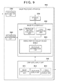
FIG. 3 is a block diagram showing the functional arrangement of the image processing apparatus 100;
FIG. 4 shows examples of ophthalmic tomograms used upon execution of an image processing function of the image processing apparatus 100;
FIG. 5 is a flowchart showing the sequence of image processing in the image processing apparatus 100;
FIG. 6 is a flowchart showing the sequence of morbid portion acquisition processing in the image processing apparatus 100;
FIG. 7 is a flowchart showing the sequence of composite image generation processing in the image processing apparatus 100;
FIG. 8 shows an example of a composite image generated by the composite image generation processing in the image processing apparatus 100;
FIG. 9 is a block diagram showing the functional arrangement of an image processing apparatus 900 according to the second embodiment of the present invention;
FIG. 10 shows an example of an ophthalmic tomogram used upon execution of an image processing function of the image processing apparatus 900;
FIG. 11 is a flowchart showing the sequence of morbid portion acquisition processing in the image processing apparatus 900;
FIG. 12 is a flowchart showing the sequence of composite image generation processing in the image processing apparatus 900;
FIG. 13 shows an example of a composite image generated by the composite image generation processing in the image processing apparatus 900; and
FIG. 14 shows states in which the boundaries of respective layers and blood vessels are detected, and the tissue forms of an eye portion are measured in various tomograms captured using an ophthalmic tomography apparatus.
DESCRIPTION OF THE EMBODIMENTS
Embodiments of the present invention will now be described in detail in accordance with the accompanying drawings.
[First Embodiment]
An overview of an image processing apparatus according to this embodiment will be described first. The image processing apparatus according to this embodiment is characterized by designating, in an ophthalmic tomogram of a patient who suffers diabetic retinopathy, layers (retina inner and outer layers) required to detect morbid portions corresponding to that disease (diabetic retinopathy).
The image processing apparatus is also characterized in that microaneurysms are detected as primary morbid portions from the retina inner layers of the designated layers, cysts are detected as associated morbid portions from the retina outer layers, and these morbid portions are projected onto a predetermined fundus image together with ophthalmic features, thereby displaying them as a composite image.
With this arrangement, the operator can easily recognize the presence/absence of leakage of plasma components from the microaneurysms, the advisability of treatments for the primary morbid portions, the priority levels of treatments for the primary morbid portions, and the like. This embodiment having these characteristic features will be described in detail below.
Note that anatomically, layers from an inner limiting membrane B1 to an inner granular layer (not shown) are defined as the retina inner layers, and those from an outer plexiform layer (not shown) to a retinal pigment epithelium layer B are defined as the retina outer layers. However, on an actual ophthalmic tomogram, since an inner plexiform layer boundary B4 which is slightly located on the inner layer side of the outer plexiform layer can be more accurately detected, layers from the inner limiting membrane B1 to the inner plexiform layer boundary B4 are described as the retina inner layers, and the retina outer layers are described as regions other than the retina inner layers in the retina in this embodiment. Of course, this embodiment can also be practiced by defining the retina inner and outer layers according to the anatomical definitions (after detection of the outer plexiform layer boundary (not shown)).
<1. Arrangement of Image Processing System>
FIG. 1 is a block diagram showing an example of an image processing system including an image processing apparatus 100 according to this embodiment.
As shown in FIG. 1, the image processing apparatus 100 and an ophthalmic tomography apparatus 102 are connected via an optical fiber and interface such as USB or IEEE1394. A data server 101 is connected to the image processing apparatus 100 and ophthalmic tomography apparatus 102 via a LAN (Local Area Network) 103 such as Ethernet®. Note that these apparatus may be connected via an external network such as the Internet.
The ophthalmic tomography apparatus 102 is an apparatus for capturing ophthalmic tomograms, and is, for example, a time-domain or Fourier-domain OCT. The ophthalmic tomography apparatus 102 three-dimensionally captures a tomogram of an eye to be examined (not shown) in response to an operation of an operator (not shown). The captured tomogram is transmitted to the image processing apparatus 100.
The data server 101 holds tomograms of an eye to be examined, ophthalmic features of the eye to be examined (anatomical features acquired from ophthalmic tomograms), normal value data of the ophthalmic features, and the like. The data server 101 holds tomograms of an eye to be examined output from the ophthalmic tomography apparatus 102 and ophthalmic features output from the image processing apparatus 100. Also, in response to a request from the image processing apparatus 100, the data server 101 transmits data (tomograms and ophthalmic features) associated with an eye to be examined, and normal value data of the ophthalmic features to the image processing apparatus 100.
<2. Hardware Arrangement of Image Processing Apparatus 100>
The hardware arrangement of the image processing apparatus 100 will be described below with reference to FIG. 2. Referring to FIG. 2, reference numeral 201 denotes a central processing unit (CPU); 202, a memory (RAM); 203, a control memory (ROM); 204, an external storage device; 205, a monitor; 206, a keyboard; 207, a mouse; and 208, an interface. The external storage device 204 stores a control program required to implement an image processing function according to this embodiment, and data used upon execution of the control program. The control program and data are loaded onto the RAM 202 via a bus 209 under the control of the CPU 201, and are executed by the CPU 201.
<3. Functional Arrangement of Image Processing Apparatus 100>
The functional arrangement of the image processing apparatus 100, which is required to implement the image processing function according to this embodiment, will be described below with reference to FIGS. 3 and 4. FIG. 3 shows the functional arrangement associated with the image processing function of the image processing apparatus 100, and FIG. 4 shows an example of an ophthalmic tomogram used upon execution of the image processing function of the image processing apparatus 100.
As shown in FIG. 3, the image processing apparatus 100 includes a tomogram acquisition unit 310, storage unit 320, image processing unit 330, composite display unit 340, and instruction acquisition unit 350.
The image processing unit 330 further includes an ophthalmic feature acquisition unit 331, layer designation unit 332, and morbid portion acquisition unit 333. The morbid portion acquisition unit 333 further includes a relevance determination unit 333-1, treatability determination unit 333-2, and treatment priority determination unit 333-3.
The composite display unit 340 further includes an image composition unit 341, relevance display unit 342, treatability display unit 343, and treatment priority display unit 344.
The respective functional blocks which configure the image processing apparatus 100 will be described in detail below.
(1) Tomogram Acquisition Unit 310
The tomogram acquisition unit 310 transmits a tomogram acquisition request to the ophthalmic tomography apparatus 102. The tomogram acquisition unit 310 receives a tomogram transmitted from the ophthalmic tomography apparatus 102 via the LAN 103 in response to this acquisition request, and stores it in the storage unit 320.
(2) Ophthalmic Feature Acquisition Unit 331
The ophthalmic feature acquisition unit 331 extracts, as ophthalmic features, an inner limiting membrane, optic nerve fiber layer boundary, ganglion cell layer boundary, inner plexiform layer boundary, outer plexiform layer boundary, boundary between inner and outer photoreceptor segments, retinal pigment epithelium boundary, optic papilla, and central fovea from the tomogram stored in the storage unit 320. Then, the ophthalmic feature acquisition unit 331 acquires an inner limiting membrane B1, inner plexiform layer boundary B4, boundary B5 between inner and outer photoreceptor segments, retinal pigment epithelium boundary B6, and central fovea F1 from the extracted ophthalmic features, as shown in FIG. 4. Also, the ophthalmic feature acquisition unit 331 stores the acquired ophthalmic features in the storage unit 320.
The ophthalmic feature extraction sequence by the ophthalmic feature acquisition unit 331 will be practically described below. The extraction sequence for extracting layer boundaries will be described first. Note that a three-dimensional tomogram to be processed is considered as a set of two-dimensional tomograms (B-scan images), and the following processing is applied to respective two-dimensional tomograms.
A two-dimensional tomogram of interest undergoes smoothing processing to remove noise components. Next, edge components are detected from the two-dimensional tomogram, and some line segments are extracted as candidates of layer boundaries based on their connectivity.
Then, from the extracted candidates, the uppermost line segment is extracted as the inner limiting membrane B1, the second uppermost line segment is extracted as the nerve fiber layer boundary B2, and the third uppermost line segment is extracted as the inner plexiform layer boundary B4. Also, the line segment, which is located on the outer layer side (the larger z-coordinate side in 4 a of FIG. 4) of the inner limiting membrane B1 and has a maximum contrast, is extracted as the boundary B5 between inner and outer photoreceptor segments. Furthermore, the lowermost line segment of the layer boundary candidates is extracted as the retinal pigment epithelium boundary B6.
Note that layer boundaries may be precisely extracted by applying a deformable model such as Snakes or a level-set method to have these line segments as initial values. Also, layer boundaries may be detected by a graph cut method.
Note that boundary extraction using a deformable model or the graph cut method may be three-dimensionally executed for a three-dimensional tomogram, or may be two-dimensionally executed for respective two-dimensional tomograms. Also, arbitrary layer boundary extraction methods may be used as long as they can extract layer boundaries from an ophthalmic tomogram.
After the layer boundaries are extracted from the ophthalmic tomogram, two recessed portions are further detected from the form of the extracted inner limiting membrane B1 in descending order of recess depth, thereby extracting the optic papilla (not shown) and central fovea F1. In this case, a shallower recessed portion is extracted as the central fovea F1, and a deeper recessed portion is extracted as the optic papilla.
(3) Layer Designation Unit 332
The layer designation unit 332 decides the types of layers designated to detect principal and associated morbid portions corresponding to a predetermined disease from the ophthalmic tomogram. The types of layers designated to detect morbid portions are decided depending on the type of disease to be diagnosed. In case of this embodiment, since a disease to be diagnosed is diabetic retinopathy, primary morbid portions are microaneurysms, and associated morbid portions are cysts, retina inner layers (P1 in 4 a of FIG. 4) including retinal blood vessels V are designated as the type of layer required to detect microaneurysms MAi. Also, as the type of layer required to detect cysts Cj, retina outer layers (P2 in 4 b of FIG. 4) where leaked plasma components have accumulated are designated. Assume that layers including the retina inner layers P1 and retina outer layers P2 are specified in advance based on the ophthalmic features acquired by the ophthalmic feature acquisition unit 331.
(4) Morbid Portion Acquisition Unit 333
The morbid portion acquisition unit 333 detects primary and associated morbid portions based on position information of the ophthalmic features acquired by the ophthalmic feature acquisition unit 331 and information of the types of layers designated by the layer designation unit 332.
More specifically, the morbid portion acquisition unit 333 detects the retinal blood vessels V from the retina inner layers designated by the layer designation unit 332, and compares the diameters of the detected retinal blood vessels V with a normal value, thereby detecting the microaneurysms MAi as the primary morbid portions. Furthermore, the morbid portion acquisition unit 333 detects the cysts Cj as the associated morbid portions from the retina outer layers designated by the layer designation unit 332.
Furthermore, the relevance determination unit 333-1 of the morbid portion acquisition unit 333 determines relevance between the morbid portions based on the distances between the detected microaneurysms MAi and cysts Cj, thereby determining treatment necessity levels. Moreover, the treatability determination unit 333-2 of the morbid portion acquisition unit 333 determines the advisability of treatments for the microaneurysms MAi based on the distances between the microaneurysms MAi and central fovea F1. Also, the treatment priority determination unit 333-3 of the morbid portion acquisition unit 333 sets treatment priority values for the respective microaneurysms MAi based on the sizes of the cysts Cj each having a shortest distance to the corresponding microaneurysm MAi. Note that details of these processes by the morbid portion acquisition unit 333 will be described later.
(5) Composite Display Unit 340
The composite display unit 340 generates a composite image for the tomogram using the distributions of the retinal blood vessels V and microaneurysms MAi, the distribution of the cysts Cj, treatment necessity level information, treatment advisability information, and treatment priority values, which are detected by the morbid portion acquisition unit 333. Note that details of the composite image generation processing will be described later.
(6) Instruction Acquisition Unit 350
The instruction acquisition unit 350 acquires an image processing start instruction in the image processing apparatus 100, a save instruction required to save the image processing results of the eye to be examined in the data server 101, and an end instruction required to end the image processing by the image processing apparatus 100. The operator inputs these instructions via, for example, the keyboard 206 and mouse 207.
Note that when the save instruction is issued, the image processing unit 330 and composite display unit 340 transmit a date and time of examination, information required to identify the eye to be examined, tomograms, ophthalmic features, and composite images to the data server 101 in association with each other.
<4. Sequence of Image Processing in Image Processing Apparatus 100>
The sequence of the image processing in the image processing apparatus 100 will be described below with reference to FIGS. 5 to 7. The image processing apparatus 100 starts the image processing shown in FIG. 5 when the instruction acquisition unit 350 acquires an image processing start instruction.
(1) Sequence of Overall Image Processing (FIG. 5)
In step S501, the tomogram acquisition unit 310 issues a tomogram acquisition request to the ophthalmic tomography apparatus 102 to acquire tomograms, and stores them in the storage unit 320. In step S502, the ophthalmic feature acquisition unit 331 acquires position information of ophthalmic features (inner limiting membrane B1, inner plexiform layer boundary B4, boundary B5 between inner and outer photoreceptor segments, retinal pigment epithelium boundary B6, and central fovea F1) from the tomograms stored in the storage unit 320.
In step S503, the layer designation unit 332 designates the types of layers according to the type of disease to be diagnosed. In step S504, the morbid portion acquisition unit 333 detects primary and associated morbid portions based on the position information of the ophthalmic features acquired by the ophthalmic feature acquisition unit 331 in step S502 and the types of layers designated by the layer designation unit 332 in step S503.
In step S505, the composite display unit 340 generates and displays a composite image using the primary and associated morbid portions detected in step S504. The instruction acquisition unit 350 determines in step S506 whether or not a save instruction required to save the image processing results in the data server 101 is acquired. If it is determined that the save instruction is acquired, the process advances to step S507.
In step S507, the image processing unit 330 and composite display unit 340 transmit the image processing results to the data server 101, and the process advances to step S508. On the other hand, if it is determined in step S506 that no save instruction is acquired, the process jumps to step S508.
The instruction acquisition unit 350 determines in step S508 whether or not an image processing end instruction is acquired. If it is determined that no end instruction is acquired, the process returns to step S501 to execute image processing for the next eye to be examined or (re-image processing for the same eye to be examined). On the other hand, if it is determined in step S508 that the image processing end instruction is acquired, the image processing ends.
(2) Sequence of Morbid Portion Acquisition Processing (FIG. 6)
Details of the morbid portion acquisition processing (step S504) executed by the morbid portion acquisition unit 333 will be described below with reference to FIG. 6.
In step S601, the morbid portion acquisition unit 333 detects retinal blood vessels V from the retina inner layers P1 of the layers designated by the layer designation unit 332. More specifically, the morbid portion acquisition unit 333 generates a projection image by accumulating pixel values in a depth direction by limiting to the retina inner layers P1, and detects the retinal blood vessels V from the generated projection image using an arbitrary known line emphasis filter.
Note that the method of detecting the retinal blood vessels V from a two-dimensional projection image has been described. However, the blood vessel detection method is not limited to this. For example, after a region of interest (ROI) is set on the retina inner layers P1, retinal blood vessels V may be three-dimensionally detected without generating any projection image using a method described in a non-patent literature (K. Lee et al.; “3-D segmentation of retinal blood vessels in spectral-domain OCT volumes of the optic nerve head”, Proceedings of SPIE Medical Imaging 2010, Vol. 7626, 76260V, 2010.)
In step S602, the morbid portion acquisition unit 333 measures the diameters of the retinal blood vessels detected in step S601. More specifically, the morbid portion acquisition unit 333 measures, as the diameters of the retinal blood vessels V, distances in directions perpendicular to the central axes of blood vessels obtained by converting retinal blood vessel regions into thin lines.
In step S603, the morbid portion acquisition unit 333 compares the diameters of the retinal blood vessels V measured in step S602 with a normal value of the diameter of a retinal blood vessel, which is read out in advance from the storage unit 320. If the measured diameter of each retinal blood vessel V is larger than the normal value by Tvd % or more, the morbid portion acquisition unit 333 determines it as a microaneurysm MAi (i=1, 2, . . . , n1), and stores a generation position (xi, yi) of that microaneurysm and a diameter Tdi of the retinal blood vessel V in the storage unit 320. Note that the diameter measurement method of the retinal blood vessels V is not limited to the method described above, and an arbitrary known measurement method may be used.
In step S604, the morbid portion acquisition unit 333 detects cysts Cj (j=1, 2, . . . , n2) from the retina outer layers P2 designated in step S503. More specifically, the morbid portion acquisition unit 333 generates a projection image by accumulating pixel values in a depth direction by limiting to the retina outer layers P2. Then, the morbid portion acquisition unit 333 labels pixels having luminance values Tg or less from the generated projection image, and detects low-luminance regions having areas Ta or more and degrees of circularity Tc or more as cysts Cj.
In step S604, the morbid portion acquisition unit 333 further detects areas Taj of the detected cysts Cj as information indicating the sizes of the associated morbid portions.
Note that the detection method of the cysts Cj is not limited to the method described above. For example, after a region of interest (ROI) is set on the retina outer layers P2, pixels having luminance values Tg or less may be labeled without generating any projection image, and low-luminance regions having volumes Tv or more and degrees of sphericity Ts or more may be detected as the cysts Cj. In this case, volumes Tvj are measured as information indicating the size of the cysts Cj.
Referring back to FIG. 6, in step S605, the relevance determination unit 333-1 measures distances LDi (distances between morbid portions) between the microaneurysms MAi acquired in step S603 and the cysts Cj detected in step S604. Furthermore, the relevance determination unit 333-1 determines, as combinations of primary and associated morbid portions, combinations (MAi, Cj) having shortest distances minLDi, which are equal to or smaller than a threshold (threshold=Tmin). In this case, a shortest distance of a microaneurysm MAi having no corresponding associated morbid portion is set to be 0.
In step S606, the treatability determination unit 333-2 calculates distances FDi between the microaneurysms MAi and central fovea F1, and sets “0” in treatable labels Li of microaneurysms MAi whose distances FDi are equal to or smaller than a predetermined distance (threshold=Tf). In this case, when a microaneurysm MAi exists in a region in which a treatment (laser irradiation) is allowed, “1” is set in Li; when it exists in a region where a treatment (laser irradiation) is not allowed, “0” is set in Li. Let n3 be the total number of microaneurysms MAi whose treatable labels Li are set to be “1”.
Furthermore, in step S606, the treatment priority determination unit 333-3 calculates treatment priority levels Pi (1≦i≦n3) for the microaneurysms MAi whose treatable labels Li are set to be “1”. More specifically, the treatment priority determination unit 333-3 sorts the cysts Cj based on the areas Taj (or volumes Tvj) of the cysts Cj calculated in step S604 to set higher treatment priority levels Pi in descending order of Taj (Tvj).
(3) Sequence of Composite Image Generation Processing (FIG. 7)
Details of the composite image generation processing (step S505) executed by the composite display unit 340 will be described below with reference to FIG. 7.
In step S701, the composite display unit 340 acquires, from the image processing unit 330, the position of the central fovea F1, the distributions of the retinal blood vessels V and microaneurysms MAi, the distribution of the cysts Cj, and values of the treatable labels Li and treatment priority levels Pi for the microaneurysms MAi.
In step S702, the image composition unit 341 superimposes the distributions of the retinal blood vessels V, microaneurysms MAi, and cysts Cj, the position of the central fovea F1, and a boundary of a treatable range (a circle having a diameter of 1 mm having the central fovea F1 as the center), which are acquired in step S701, on a predetermined fundus image generated from a tomogram. Also, the composite display unit 340 displays the generated composite image.
Also, the relevance display unit 342 displays combinations of primary morbid portions (microaneurysms MAi) and associated morbid portions (cysts Cj), which are determined to have relevance in step S605, in a mode which can identify relevance from each microaneurysm MAi to a corresponding cyst Cj. In this embodiment, arrows are displayed from the microaneurysms MAi to the cysts Cj on the composite image generated in step S702.
Note that the relevance display method is not limited to this, and an arbitrary method may be used as long as it can identify that morbid portions have relevance. For example, a frame which bounds a microaneurysm MAi and cyst Cj, which are determined to have relevance, may be displayed. Alternatively, only when the operator moves a mouse cursor to the vicinity of a microaneurysm MAi, information indicating relevance may be displayed.
In step S703, the treatability display unit 343 displays microaneurysms MAi having treatable labels Li=0 in a mode (color) different from the remaining microaneurysms based on the treatable labels Li of the microaneurysms MAi calculated in step S606. In this embodiment, the retinal blood vessels V and microaneurysms MAi having Li=1 are displayed in red, and microaneurysms MAi having Li=0 are displayed in gray.
Note that the treatability display mode is not limited to this. For example, X marks may be displayed beside the microaneurysms MAi having treatable labels Li=0. Alternatively, only when the operator moves a mouse cursor to the vicinity of a microaneurysm MAi, information indicating treatability may be displayed. Alternatively, microaneurysms MAi which are located near the boundary of the treatable range may be highlighted since careful examinations are required for them, and distances from the central fovea F1 may be displayed in the vicinity of the microaneurysms MAi.
In step S704, the treatment priority display unit 344 displays the treatment priority levels Pi calculated in step S606 on the composite image. In this embodiment, values of the treatment priority levels Pi are displayed in the vicinity of the microaneurysms MAi.
Note that the display mode of the treatment priority levels Pi is not limited to this. For example, treatment priority levels may be associated with color bars, and the microaneurysms MAi in the composite image may be displayed in colors indicating the treatment priority levels. Alternatively, only when the operator moves a mouse cursor to the vicinity of a microaneurysm MAi, information indicating a treatment priority level may be displayed. Alternatively, only treatment priority levels higher than a predetermined value Tp may be displayed on the composite image as information indicating the treatment priority levels.
<5. Example of Composite Image>
A composite image generated by the composite image generation processing in the image processing apparatus 100 will be described below. FIG. 8 shows an example of a composite image generated by the composite image generation processing in the image processing apparatus 100.
As shown in FIG. 8, a composite image generated by the image processing apparatus 100 composites and displays the primary morbid portions detected from the retina inner layers P1 and the associated morbid portions detected from the retina outer layers P2. With this image, the operator can easily recognize the presence/absence of leakage of plasma components from microaneurysms, priority levels of treatments for the primary morbid portions, and the like.
Also, since the position of the central fovea F1 is displayed at the same time, the operator can easily recognize whether or not each microaneurysm MAi is located within a laser treatable range (the advisability of treatments for the primary morbid portions).
As can be seen from the above description, the image processing apparatus 100 of this embodiment allows the operator to easily recognize the relevance between morbid portions which exist in a plurality of layers.
[Second Embodiment]
The first embodiment has explained the arrangement in which when a disease to be diagnosed is diabetic retinopathy, primary morbid portions are microaneurysms, and associated morbid portions are cysts, a composite image is generated for a predetermined tomogram. However, the present invention is not limited to this.
For example, when morbid portions exist in different portions (cell nuclei and axons) of cells which travel across a plurality of layers like glaucoma, it is important to allow an operator to easily recognize relevance between these morbid portions.
In this embodiment, in consideration of such characteristics of a disease such as glaucoma, a composite image, which composites an image indicating the thickness of a layer including cell nuclei of ganglion cells, an image indicating the thickness of a layer including axons, and an image indicating a nerve fiber distribution, is displayed. With this arrangement, the operator can easily recognize whether or not identical cells or tissues suffer morbid portions which exist in different layers.
A practical description will be given taking glaucoma as an example. In the case of glaucoma, since cell nuclei of ganglion cells exist in a ganglion cell layer L2 and axons exist in a nerve fiber layer L1 in general, disorders of cell nuclei of ganglion cells occur prior to those of axons in an early stage of the disease. For this reason, for example, when a thinned region of the nerve fiber layer L1 is detected, a region (ganglion cell layer L2) including cell nuclei of ganglion cells which travel in the thinned region also suffers from abnormality (thinning).
Hence, in this embodiment, when abnormality is detected by measuring tissue forms such as layer thicknesses from an ophthalmic tomogram, a composite image which superimposes images indicating a ganglion cell layer thickness distribution of a macular area, a nerve fiber layer thickness distribution of an optic papilla, and a nerve fiber distribution in an eye fundus is displayed. With this arrangement, the operator can easily confirm whether or not a nerve fiber which travels through a morbid portion (thinning of a layer) which exists in the nerve fiber layer L1 passes through that (thinning of a layer) in the ganglion cell layer L2. As a result, the operator can easily judge whether disorders of cell nuclei of ganglion cells are detected or noise components or the like are erroneously detected, thus improving reliability of morbid portion detection results.
An image processing apparatus 900 according to this embodiment will be described below focusing on differences from the image processing apparatus 100 according to the first embodiment.
Note that a case will be explained below wherein a disease to be diagnosed is glaucoma.
Also, in the following description, assume that the layer thicknesses of the ganglion cell layer L2 or statistical values (deviations) associated with differences between the layer thicknesses and a normal value are used as values which represent the degrees of disorders (thinning morbid portions) of cell nuclei of ganglion cells. However, the present invention is not limited to this, and GCC (Ganglion Cell Complex) layer thicknesses or deviations of the layer thicknesses may be used.
<1. Functional Arrangement of Image Processing Apparatus 900>
The functional arrangement of the image processing apparatus 900 according to this embodiment will be described below with reference to FIGS. 9 and 10. FIG. 9 is a block diagram showing the functional arrangement of the image processing apparatus 900 according to this embodiment. FIG. 10 shows an example of an ophthalmic tomogram used upon execution of an image processing function of the image processing apparatus 900.
(1) Tomogram Acquisition Unit 310
A tomogram acquisition unit 310 transmits a tomogram acquisition request to an ophthalmic tomography apparatus 102. Note that tomograms to be acquired in this embodiment are those which include a macular area and optic papilla. The acquired tomograms are stored in a storage unit 320.
(2) Ophthalmic Feature Acquisition Unit 931
An ophthalmic feature acquisition unit 931 extracts, as ophthalmic features, an inner limiting membrane B1, nerve fiber layer boundary B2, ganglion cell layer boundary B3, inner plexiform layer boundary B4, boundary B5 between inner and outer photoreceptor segments, retinal pigment epithelium boundary B6, and central fovea F1 from the tomograms stored in the storage unit 320 (see FIG. 10).
Also, the ophthalmic feature acquisition unit 931 extracts the central position of an optic papilla D1 and the positions of end portions (RPE tips) of the retinal pigment epithelium boundary B6 in the optic papilla. Note that the positions of the end portions of the retinal pigment epithelium boundary B6 are calculated for respective B-scan images.
Note that the extraction method of the respective layer boundaries B1, B2, and B4 to B6, the central fovea F1, and the optic papilla D1 is the same as that described in the first embodiment. Hence, the extraction method of the ganglion cell layer boundary B3 will be describe below.
That is, after the nerve fiber layer boundary B2 and inner plexiform layer boundary B4 are acquired, local regions are set at respective points (x, y) in a region bounded by these boundaries to calculate variances of pixel values. Then, it is determined that a layer boundary exists in local regions with maximum variances, and these boundary positions are connected in the x- and y-axis directions, thereby extracting the ganglion cell layer boundary B3 (see FIG. 10). Note that the ophthalmic features extracted in this way are stored in the storage unit 320.
Furthermore, the ophthalmic feature acquisition unit 931 acquires, from the storage unit 320, pieces of information Nk (k=1, 2, . . . , n) indicating the distribution of ganglion cells in an eye fundus (the distribution of ganglion cells projected onto an x-y plane in FIG. 10). The pieces of distribution information of the ganglion cells in the eye fundus can be acquired from, for example, an SLO (Scanning Laser Opthalmoscope) image captured in a red-Free mode of an SLO. In this embodiment, assume that curves Nk (k=1, 2, . . . , n) indicating average nerve fibers generated based on SLO images obtained by capturing a plurality of healthy eyes in the red-Free mode are saved in advance in the storage unit 320.
Note that the nerve fiber distribution information acquisition method is not limited to this. For example, a surface image acquisition unit (not shown) may be included in the image processing apparatus 900, an SLO image (red-Free mode) of the same patient as the ophthalmic tomograms may be acquired from the surface image acquisition unit and may be stored in the storage unit 320. Then, the stored SLO image may be acquired.
(3) Layer Designation Unit 932
A layer designation unit 932 designates the nerve fiber layer L1 as a first layer and the ganglion cell layer L2 as a second layer. Note that the nerve fiber layer L1 is formed by gathering axons of the ganglion cell layer L2, and the ganglion cell layer L2 is formed by gathering cell nuclei of ganglion cells.
(4) Morbid Portion Acquisition Unit 933
A morbid portion acquisition unit 933 measures nerve fiber layer thicknesses and ganglion cell layer thicknesses based on the ophthalmic features acquired by the ophthalmic feature acquisition unit 931. Also, the morbid portion acquisition unit 933 detects thinned regions by comparing the measured nerve fiber layer thicknesses and ganglion cell layer thicknesses with their normal values. Furthermore, a relevance determination unit 933-1 determines relevance between the detected thinned regions and tissue structure (nerve fiber distribution) information acquired by the ophthalmic feature acquisition unit 931. Note that details of these processes by the morbid portion acquisition unit 933 will be described later.
(5) Composite Display unit 940
A composite display unit 940 acquires the tissue structure (nerve fiber distribution) information, the layer thickness distribution of the nerve fiber layer L1, and that of the ganglion cell layer L2 from the morbid portion acquisition unit 933. Also, the composite display unit 940 acquires thinned regions NFi as morbid portions of the nerve fiber layer L1, thinned regions GCj as morbid portions of the ganglion cell layer L2, and detection reliabilities DRi of the respective thinned regions. Then, the composite display unit 940 generates a composite image for an SLO image using these pieces of information. Note that details of the composite image generation processing will be described later.
<2. Sequence of Image Processing in Image Processing Apparatus 900>
(1) Sequence of Morbid Portion Acquisition Processing (FIG. 11)
Details of morbid portion acquisition processing (step S504) executed by the morbid portion acquisition unit 933 will be described below with reference to FIG. 11.
In step S1101, the morbid portion acquisition unit 933 acquires the layer boundaries, the positions of the central fovea F1 and optic papilla D1, and tissue structure (nerve fiber distribution) information acquired by the ophthalmic feature acquisition unit 931, and normal values associated with respective layer thicknesses stored in the storage unit 320.
In step S1102, the morbid portion acquisition unit 933 measures nerve fiber layer thicknesses and ganglion cell layer thicknesses at respective points (x, y) in the eye fundus based on the layer boundaries acquired in step S1101. In this case, the morbid portion acquisition unit 933 does not measure nerve fiber layer thicknesses and ganglion cell layer thicknesses within the range of a diameter of 1 mm having the central fovea F1 as the center, and the interior of a Disc boundary of the optic papilla.
Note that in this embodiment, the position of the Disc boundary is set as follows. That is, lines Ai obtained by connecting end portions of the acquired retinal pigment epithelium boundary B6 in respective B-scan images (image numbers i) are calculated. Intersections E1i and E2i between the inner limiting membrane B1 and lines Ai′ moved by a threshold Th toward the inner layer side in directions perpendicular to the lines Ai are calculated for respective B-scan images. Sets {E1i, E2i} of the obtained intersections are smoothly connected in an x-y plane to obtain the Disc boundary.
Referring back to FIG. 11, in step S1103, the morbid portion acquisition unit 933 compares the nerve fiber layer thicknesses and ganglion cell layer thicknesses with their normal values (values having given ranges). When the thicknesses are smaller than the normal values, corresponding regions are determined and detected as the thinned regions NFi of the nerve fiber layer L1 and the thinned regions GCj of the ganglion cell layer L2.
In step S1104, the relevance determination unit 933-1 determines relevance between the thinned regions NFi and GCj acquired by the morbid portion acquisition unit 933 based on the tissue structure (nerve fiber distribution) information acquired by the ophthalmic feature acquisition unit 931. That is, the relevance determination unit 933-1 determines whether or not the thinned regions NFi of the nerve fiber layer L1 and the thinned regions GCj of the ganglion cell layer L2 exist on an identical nerve fiber (on Nk).
At the time of determination, the coordinate system of the tissue structure (nerve fiber distribution) information Nk(x, y) and those of the morbid portion distributions NFi (x, y) and GCj (x, y) are aligned as follows. That is, since the positions of the central fovea F1 and optic papilla D1 are already calculated on the respective coordinate systems, translations (x, y) and rotation parameters for composite position alignment are calculated so that these two points are set at identical positions. Note that in this embodiment, since uniform image capturing conditions are adopted upon acquisition of SLO images and tomograms, the tissue structure information and morbid portion distributions are set in advance to have the same pixel size.
The morbid portion acquisition unit 933 further superimposes the tissue structure (nerve fiber distribution) information and morbid portion distributions based on the position alignment parameter values obtained as a result of position alignment.
Moreover, the morbid portion acquisition unit 933 calculates the thinned regions NFi of the nerve fibers layer L1 which exist on respective nerve fibers Nk. When the thinned regions NFi exist on the nerve fibers Nk, the morbid portion acquisition unit 933 checks whether or not the thinned region GCj exists on the same nerve fiber Nk. If the thinned region NFi of the nerve fiber layer L1 and the thinned region GCj of the ganglion cell layer L2 exist on the same nerve fiber Nk, an identical ganglion cell is more likely to have sustained damage. For this reason, the morbid portion acquisition unit 933 sets “1” in the detection reliability DRi of that thinned region NFi of the nerve fiber layer L1.
Note that the setting method of the detection reliability DRi of each thinned region NFi of the nerve fiber layer L1 is not limited to this. For example, in place of defining the reliability DRi by binary data (0 or 1), as described above, the reliability DRi may be defined by multi-valued data so as to be set to be higher in proportion to the number of travels Nk which pass through both the thinned regions NFi and GCj.
(2) Sequence of Composite Image Generation Processing (FIG. 12)
Details of the composite image generation processing (step S505) executed by the composite display unit 940 will be described below with reference to FIG. 12.
In step S1201, the composite display unit 940 acquires the tissue structure (nerve fiber distribution) information acquired in step S1101 and the layer thickness distributions of the nerve fiber layer L1 and ganglion cell layer L2 acquired in step S1102 from an image processing unit 930. Furthermore, the composite display unit 940 acquires the thinned regions NFi of the nerve fiber layer L1 and the thinned regions GCj of the ganglion cell layer L2 acquired in step S1103 and the detection reliabilities DRi of the thinned regions NFi acquired in step S1104 from the image processing unit 930.
In step S1202, a tissue structure display unit 943 displays the tissue structure (nerve fiber distribution) information acquired in step S1201 on a monitor 205.
In step S1203, an image composition unit 341 displays following pieces of information on the tissue structure (nerve fiber travel) information displayed in step S1202. That is, the image composition unit 341 translucently composites and displays a Deviation map of the nerve fiber layer thicknesses and the thinned regions NFi of the nerve fiber layer on a region of a diameter R1 having the optic papilla D1 as the center. Also, the image composition unit 341 translucently composites and displays a Deviation map of the ganglion cell layer thicknesses and the thinned regions GCj of the ganglion cell layer on the remaining region. Furthermore, the image composition unit 341 displays standard nerve fiber layer thickness measurement positions on the optic papilla (positions M1 on a circumference having a diameter of 3.45 mm having the optic papilla D1 as the center) as a reference.
Note that the composite display mode is not limited to this. For example, the detection reliabilities DRi of the thinned regions NFi acquired in step S1104 may be displayed in the vicinity of the thinned regions NFi on the displayed composite image. Alternatively, in place of displaying the tissue structure (nerve fiber distribution) information on the entire surface of the composite image, only nerve fibers Nk which pass through the thinned regions NFi or GCj may be displayed. Alternatively, in place of always displaying the tissue structure information and detection reliabilities DRi, they may be displayed at only a position designated by a mouse cursor.
<3. Example of Composite Image>
A composite image generated by the composite image generation processing in the image processing apparatus 900 will be described below. FIG. 13 shows an example of a composite image generated by the composite image generation processing in the image processing apparatus 900.
As shown in FIG. 13, in a composite image generated by the image processing apparatus 900, the thinned regions of the ganglion cell layer L2 of the macular area and the thinned regions of the nerve fiber layer L1 of the optic papilla are composited and displayed on information indicating the nerve fiber distribution. With this display, the operator can easily recognize whether or not the thinned regions as morbid portions of glaucoma which exist in different layers correspond to identical cells or tissues.
As can be seen from the above description, the image processing apparatus 900 according to this embodiment allows the operator to easily recognize relevance between morbid portions which exist in a plurality of layers.
[Other Embodiments]
Aspects of the present invention can also be realized by a computer of a system or apparatus (or devices such as a CPU or MPU) that reads out and executes a program recorded on a memory device to perform the functions of the above-described embodiment(s), and by a method, the steps of which are performed by a computer of a system or apparatus by, for example, reading out and executing a program recorded on a memory device to perform the functions of the above-described embodiment(s). For this purpose, the program is provided to the computer for example via a network or from a recording medium of various types serving as the memory device (for example, computer-readable medium).
While the present invention has been described with reference to exemplary embodiments, it is to be understood that the invention is not limited to the disclosed exemplary embodiments. The scope of the following claims is to be accorded the broadest interpretation so as to encompass all such modifications and equivalent structures and functions.
This application claims the benefit of Japanese Patent Application No. 2010-259519 filed Nov. 19, 2010, which is hereby incorporated by reference herein in its entirety.

Claims (10)

What is claimed is:
1. An image processing apparatus for processing a tomogram of an eye fundus, the apparatus comprising:
a memory; and
a processor that is in communication with the memory, the processor configured to function as units comprising:
(a) a feature acquisition unit configured to acquire anatomical features of the tomogram;
(b) a designation unit configured to designate a first layer and a second layer, for detecting morbid portions corresponding to a predetermined disease, from a plurality of layers specified by the anatomical features acquired by said feature acquisition unit;
(c) a morbid portion acquisition unit configured to detect primary morbid portions from the first layer and secondary morbid portions from the second layer, the primary morbid portions and the secondary morbid portions being corresponded to the predetermined disease;
(d) a relevance determination unit configured to determine an existence or absence of relevance between of primary morbid portions and the secondary morbid portions detected by said morbid portion acquisition unit;
(e) a priority determination unit configured to determine treatment priority levels for the primary morbid portions based on the secondary morbid portions;
(f) a generation unit configured to generate a composite image by projecting the primary morbid portions and the secondary morbid portions detected by said morbid portion acquisition unit onto a predetermined two-dimensional image; and
(g) a display control unit configured to control a display unit to display the treatment priority levels determined by said priority determination unit and the composite image generated by said generation unit in a form which allows identification of primary morbid portions and secondary morbid portions in which the relevance is determined to exist by said relevance determination unit and primary morbid portions and secondary morbid portions in which the relevance is determined to be absent by said relevance determination unit.
2. The apparatus according to claim 1, wherein when a distance between the primary morbid portions and the secondary morbid portions is not more than a predetermined threshold, said display control unit controls the display unit to display the primary morbid portions and the secondary morbid portions in a mode which allows identification of relevance between the primary morbid portions and the secondary morbid portions.
3. The apparatus according to claim 2, wherein said display control unit controls the display unit to display a circle indicating a position of a central fovea on the composite image.
4. The apparatus according to claim 3, wherein said display control unit controls the display unit to display a primary morbid portion of the primary morbid portions with a priority according to a size of the primary morbid portion.
5. The apparatus according to claim 4, wherein the predetermined disease is diabetic retinopathy, the primary morbid portion is a microaneurysm, the first layer is a retina inner layer, the secondary morbid portion is a cyst, and the second layer is a retina outer layer.
6. The apparatus according to claim 1, wherein the two-dimensional image is an image which indicates a nerve fiber distribution of the eye fundus, and
wherein when the primary morbid portions and the secondary morbid portions exist on an identical nerve fiber on the two-dimensional image, said display control unit controls the display unit to display the primary morbid portions and the secondary morbid portions in a mode which allows identification of relevance between the primary morbid portions and the secondary morbid portions.
7. The apparatus according to claim 6, wherein the predetermined disease is glaucoma, and
wherein the first morbid portion is a thinned region of a nerve fiber layer and the second morbid portion is a thinned region of a ganglion cell layer.
8. The apparatus according to claim 1, wherein the priority determination unit determines treatment priority levels for the primary morbid portions based on sizes of the secondary morbid portions.
9. An image processing method for processing a tomogram of an eye fundus, the method comprising:
a feature acquisition step of acquiring anatomical features of the tomogram;
a designation step of designating a first layer and a second layer, for detecting morbid portions corresponding to a predetermined disease, from a plurality of layers specified by the anatomical features acquired in the feature acquisition step;
a morbid portion acquisition step of detecting primary morbid portions from the first layer and secondary morbid portions from the second layer, the primary morbid portions and the secondary morbid portions being corresponded to the predetermined disease;
a relevance determination step of determining an existence or absence of relevance between the primary morbid portions and the secondary morbid portions detected in the morbid portion acquisition step;
a priority determination step of determining treatment priority levels for the primary morbid portions based on the secondary morbid portions;
a generation step of generating a composite image by projecting the primary morbid portions and the secondary morbid portions detected in the morbid portion acquisition step onto a predetermined two-dimensional image; and
a display step of controlling a display unit to display the treatment priority levels determined in the priority determination step and the composite image generated in the generation step in a form which allows identification of primary morbid portions and secondary morbid portions in which the relevance is determined to exist in the relevance determination step and primary morbid portions and secondary morbid portions in which the relevance is determined to be absent in the relevance determination step.
10. A non-transitory computer-readable storage medium including a program stored therein for executing an image processing method for processing a tomogram of an eye fundus, the image processing method comprising:
a feature acquisition step of acquiring anatomical features of the tomogram;
a designation step of designating a first layer and a second layer, for detecting morbid portions corresponding to a predetermined disease, from a plurality of layers specified by the anatomical features acquired in the feature acquisition step;
a morbid portion acquisition step of detecting primary morbid portions from the first layer and secondary morbid portions from the second layer, the primary morbid portions and the secondary morbid portions being corresponded to the predetermined disease;
a relevance determination step of determining an existence or absence of relevance between the primary morbid portions and the secondary morbid portions detected in the morbid portion acquisition step;
a priority determination step of determining treatment priority levels for the primary morbid portions based on the secondary morbid portions;
a generation step of generating a composite image by projecting the primary morbid portions and the secondary morbid portions detected in the morbid portion acquisition step onto a predetermined two-dimensional image; and
a display step of displaying the treatment priority levels determined in the priority determination step and the composite image generated in the generation step in a form which allows identification of primary morbid portions and secondary morbid portions in which the relevance is determined to exist in the relevance determination step and primary morbid portions and secondary morbid portions in which the relevance is determined to be absent in the relevance determination step.
US13/271,604 2010-11-19 2011-10-12 Image processing apparatus and image processing method Active 2035-02-24 US9355446B2 (en)

Priority Applications (1)

Application Number Priority Date Filing Date Title
US15/137,105 US9943224B2 (en) 2010-11-19 2016-04-25 Image processing apparatus and image processing method

Applications Claiming Priority (2)

Application Number Priority Date Filing Date Title
JP2010-259519 2010-11-19
JP2010259519A JP5702991B2 (en) 2010-11-19 2010-11-19 Image processing apparatus and image processing method

Related Child Applications (1)

Application Number Title Priority Date Filing Date
US15/137,105 Continuation US9943224B2 (en) 2010-11-19 2016-04-25 Image processing apparatus and image processing method

Publications (2)

Publication Number Publication Date
US20120130270A1 US20120130270A1 (en) 2012-05-24
US9355446B2 true US9355446B2 (en) 2016-05-31

Family

ID=45346136

Family Applications (2)

Application Number Title Priority Date Filing Date
US13/271,604 Active 2035-02-24 US9355446B2 (en) 2010-11-19 2011-10-12 Image processing apparatus and image processing method
US15/137,105 Active US9943224B2 (en) 2010-11-19 2016-04-25 Image processing apparatus and image processing method

Family Applications After (1)

Application Number Title Priority Date Filing Date
US15/137,105 Active US9943224B2 (en) 2010-11-19 2016-04-25 Image processing apparatus and image processing method

Country Status (5)

Country Link
US (2) US9355446B2 (en)
EP (1) EP2455912B1 (en)
JP (1) JP5702991B2 (en)
KR (1) KR101426122B1 (en)
CN (1) CN102479385B (en)

Cited By (4)

* Cited by examiner, † Cited by third party
Publication number Priority date Publication date Assignee Title
US9943224B2 (en) 2010-11-19 2018-04-17 Canon Kabushiki Kaisha Image processing apparatus and image processing method
US10388012B2 (en) 2015-03-25 2019-08-20 Canon Kabushiki Kaisha Image processing apparatus, image processing method, and program for identifying cells of blood vessel wall
US20190272631A1 (en) * 2018-03-01 2019-09-05 Carl Zeiss Meditec, Inc. Identifying suspicious areas in ophthalmic data
US10973406B2 (en) 2018-03-06 2021-04-13 Canon Kabushiki Kaisha Image processing apparatus, image processing method, and non-transitory computer readable medium

Families Citing this family (36)

* Cited by examiner, † Cited by third party
Publication number Priority date Publication date Assignee Title
JP4909378B2 (en) 2009-06-02 2012-04-04 キヤノン株式会社 Image processing apparatus, control method therefor, and computer program
JP5904711B2 (en) 2011-02-01 2016-04-20 キヤノン株式会社 Image processing apparatus, image processing method, and program
JP6025311B2 (en) 2011-08-01 2016-11-16 キヤノン株式会社 Ophthalmic diagnosis support apparatus and method
JP5955163B2 (en) 2011-09-06 2016-07-20 キヤノン株式会社 Image processing apparatus and image processing method
JP5947561B2 (en) 2012-02-20 2016-07-06 キヤノン株式会社 Image forming apparatus and image forming method
JP6114495B2 (en) 2012-02-20 2017-04-12 キヤノン株式会社 Image display device, image display method, and imaging system
JP6101048B2 (en) 2012-02-20 2017-03-22 キヤノン株式会社 Image processing apparatus and image processing method
JP6166871B2 (en) * 2012-07-26 2017-07-19 国立大学法人京都大学 Blood vessel age output device, blood vessel age output method, and program
EP2693399B1 (en) * 2012-07-30 2019-02-27 Canon Kabushiki Kaisha Method and apparatus for tomography imaging
US9230062B2 (en) * 2012-11-06 2016-01-05 20/20 Vision Center, Llc Systems and methods for enabling customers to obtain vision and eye health examinations
WO2014085911A1 (en) * 2012-12-05 2014-06-12 Tornado Medical Systems, Inc. System and method for wide field oct imaging
JP6092659B2 (en) 2013-02-28 2017-03-08 キヤノン株式会社 Image processing apparatus and image processing method
JP6200168B2 (en) * 2013-02-28 2017-09-20 キヤノン株式会社 Image processing apparatus and image processing method
JP6198410B2 (en) 2013-02-28 2017-09-20 キヤノン株式会社 Image processing apparatus and image processing method
JP6429447B2 (en) * 2013-10-24 2018-11-28 キヤノン株式会社 Information processing apparatus, comparison method, alignment method, and program
JP6312123B2 (en) * 2013-11-19 2018-04-18 国立大学法人京都大学 Cell determination method, cell determination apparatus, and cell determination program
JP6588462B2 (en) * 2013-12-23 2019-10-09 アールエスビーブイ,リミティド ライアビリティ カンパニー Wide-field retinal image acquisition system and method
JP6410498B2 (en) * 2014-07-08 2018-10-24 キヤノン株式会社 Ophthalmic apparatus and control method thereof
CN105069803A (en) * 2015-08-19 2015-11-18 西安交通大学 Classifier for micro-angioma of diabetes lesion based on colored image
JP6656063B2 (en) * 2016-04-15 2020-03-04 キヤノン株式会社 Image processing apparatus, image processing method, and program
CN105997152A (en) * 2016-06-13 2016-10-12 杭州融超科技有限公司 Integrated pupil measuring device and data processing method and system with integrated pupil measuring device
CN106682389B (en) * 2016-11-18 2019-01-15 武汉大学 A kind of Eye disease for monitoring hypertension initiation is health management system arranged
JP6843602B2 (en) * 2016-12-05 2021-03-17 キヤノン株式会社 Image display device, image display method, and program
US10810371B2 (en) 2017-04-06 2020-10-20 AIBrain Corporation Adaptive, interactive, and cognitive reasoner of an autonomous robotic system
US10839017B2 (en) 2017-04-06 2020-11-17 AIBrain Corporation Adaptive, interactive, and cognitive reasoner of an autonomous robotic system utilizing an advanced memory graph structure
US10963493B1 (en) 2017-04-06 2021-03-30 AIBrain Corporation Interactive game with robot system
US10929759B2 (en) 2017-04-06 2021-02-23 AIBrain Corporation Intelligent robot software platform
US11151992B2 (en) * 2017-04-06 2021-10-19 AIBrain Corporation Context aware interactive robot
CN107423726A (en) * 2017-08-12 2017-12-01 合肥全飞信息科技有限公司 A kind of illness in eye identifies cell phone application design method
WO2019079310A1 (en) * 2017-10-16 2019-04-25 Massachusetts Institute Of Technology Systems, devices and methods for non-invasive hematological measurements
CN116807381A (en) * 2017-12-28 2023-09-29 株式会社尼康 Image processing method, image processing program, image processing device, image display device, and image display method
CN110037651B (en) * 2018-01-15 2022-03-25 江威 Method and device for controlling quality of fundus image
JP7154044B2 (en) * 2018-06-13 2022-10-17 株式会社トプコン slit lamp microscope and ophthalmic system
GB201908052D0 (en) * 2019-06-06 2019-07-24 Nisonic As Alignment of ultrasound image
CN114828732A (en) * 2019-10-17 2022-07-29 株式会社尼康 Image processing method, image processing apparatus, and image processing program
CN110853009B (en) * 2019-11-11 2023-04-28 北京端点医药研究开发有限公司 Retina pathology image analysis system based on machine learning

Citations (12)

* Cited by examiner, † Cited by third party
Publication number Priority date Publication date Assignee Title
US20040102682A1 (en) 2002-11-26 2004-05-27 Gudrun Zahlmann Method and system for supporting the evaluation of a picture of an eye
US20060119858A1 (en) 2004-12-02 2006-06-08 Knighton Robert W Enhanced optical coherence tomography for anatomical mapping
US20070216909A1 (en) 2006-03-16 2007-09-20 Everett Matthew J Methods for mapping tissue with optical coherence tomography data
US20070263227A1 (en) * 2006-05-12 2007-11-15 The General Hospital Corporation Processes, arrangements and systems for providing a fiber layer thickness map based on optical coherence tomography images
CN101204318A (en) 2006-12-22 2008-06-25 株式会社拓普康 Fundus oculi observation device and fundus oculi image display device
US20080309881A1 (en) 2007-06-15 2008-12-18 University Of Southern California Pattern analysis of retinal maps for the diagnosis of optic nerve diseases by optical coherence tomography
JP2009066015A (en) 2007-09-10 2009-04-02 Univ Of Tokyo Fundus observation apparatus, ophthalmologic image processer, and program
JP2009089792A (en) 2007-10-04 2009-04-30 Topcon Corp Fundus oculi observation device and fundus oculi image processing device
US20100202677A1 (en) 2008-10-17 2010-08-12 Canon Kabushiki Kaisha Image processing apparatus and image processing method for a tomogram of an eye region
US20110137157A1 (en) 2009-12-08 2011-06-09 Canon Kabushiki Kaisha Image processing apparatus and image processing method
US20120063660A1 (en) 2009-06-02 2012-03-15 Canon Kabushiki Kaisha Image processing apparatus, control method thereof, and computer program
US20120194782A1 (en) 2011-02-01 2012-08-02 Canon Kabushiki Kaisha Image processing apparatus, image processing method and storage medium

Family Cites Families (7)

* Cited by examiner, † Cited by third party
Publication number Priority date Publication date Assignee Title
IL125614A (en) 1998-07-31 2003-01-12 Amiram Grinvald System and method for non-invasive imaging of retinal function
JP4733809B2 (en) 2000-05-23 2011-07-27 株式会社東芝 Radiation therapy planning device
JP2006022045A (en) * 2004-07-08 2006-01-26 Kaneka Corp METHOD FOR ISOLATING AND PURIFYING OPTICALLY ACTIVE 1-t-BUTOXYCARBONYL-3-AMINOPYRROLIDINE SALT
US8249326B2 (en) * 2005-11-25 2012-08-21 British Columbia Cancer Agency Branch Apparatus and methods for automated assessment of tissue pathology
JP4819851B2 (en) * 2008-07-31 2011-11-24 キヤノン株式会社 Diagnosis support apparatus and method, program, and recording medium
JP2010148635A (en) * 2008-12-25 2010-07-08 Topcon Corp Ophthalmic apparatus for laser medical treatment
JP5702991B2 (en) 2010-11-19 2015-04-15 キヤノン株式会社 Image processing apparatus and image processing method

Patent Citations (28)

* Cited by examiner, † Cited by third party
Publication number Priority date Publication date Assignee Title
US7283653B2 (en) 2002-11-26 2007-10-16 Siemens Aktiengesellschaft Method and system for supporting the evaluation of a picture of an eye
CN1717678A (en) 2002-11-26 2006-01-04 西门子公司 Supporting the evaluation of a picture of an eye
US20040102682A1 (en) 2002-11-26 2004-05-27 Gudrun Zahlmann Method and system for supporting the evaluation of a picture of an eye
US7301644B2 (en) 2004-12-02 2007-11-27 University Of Miami Enhanced optical coherence tomography for anatomical mapping
US20090180123A1 (en) 2004-12-02 2009-07-16 Carl Zeiss Meditec, Inc. To University Of Miami Enhanced optical coherence tomography for anatomical mapping
US20080068560A1 (en) 2004-12-02 2008-03-20 Knighton Robert W Enhanced optical coherence tomography for anatomical mapping
US7924429B2 (en) 2004-12-02 2011-04-12 University Of Miami Enhanced optical coherence tomography for anatomical mapping
US20060119858A1 (en) 2004-12-02 2006-06-08 Knighton Robert W Enhanced optical coherence tomography for anatomical mapping
US20100208201A1 (en) 2004-12-02 2010-08-19 University Of Miami Enhanced optical coherence tomography for anatomical mapping
US7659990B2 (en) 2004-12-02 2010-02-09 University Of Miami Enhanced optical coherence tomography for anatomical mapping
US7505142B2 (en) 2004-12-02 2009-03-17 University Of Miami Enhanced optical coherence tomography for anatomical mapping
US20070216909A1 (en) 2006-03-16 2007-09-20 Everett Matthew J Methods for mapping tissue with optical coherence tomography data
US20070263227A1 (en) * 2006-05-12 2007-11-15 The General Hospital Corporation Processes, arrangements and systems for providing a fiber layer thickness map based on optical coherence tomography images
US7794083B2 (en) 2006-12-22 2010-09-14 Kabushiki Kaisha Topcon Fundus oculi observation device and fundus oculi image display device
JP2008154704A (en) 2006-12-22 2008-07-10 Topcon Corp Fundus oculi observation device, fundus oculi image display device, and program
CN101204318A (en) 2006-12-22 2008-06-25 株式会社拓普康 Fundus oculi observation device and fundus oculi image display device
US20080151187A1 (en) 2006-12-22 2008-06-26 Kabushi Kaisha Topcon Fundus oculi observation device and fundus oculi image display device
CN101778593A (en) 2007-06-15 2010-07-14 南加州大学 Pattern analysis of retinal maps for diagnosis of optic nerve diseases by optical coherence tomography
US20080309881A1 (en) 2007-06-15 2008-12-18 University Of Southern California Pattern analysis of retinal maps for the diagnosis of optic nerve diseases by optical coherence tomography
US8474978B2 (en) 2007-06-15 2013-07-02 University Of Southern California Pattern analysis of retinal maps for the diagnosis of optic nerve diseases by optical coherence tomography
US20100194757A1 (en) 2007-09-10 2010-08-05 Kabushiki Kaisha Topcon Fundus oculi observation device, ophthalmologic image processing device, and program
JP2009066015A (en) 2007-09-10 2009-04-02 Univ Of Tokyo Fundus observation apparatus, ophthalmologic image processer, and program
US8408704B2 (en) 2007-09-10 2013-04-02 The University Of Tokyo Fundus oculi observation device, ophthalmologic image processing device, and program
JP2009089792A (en) 2007-10-04 2009-04-30 Topcon Corp Fundus oculi observation device and fundus oculi image processing device
US20100202677A1 (en) 2008-10-17 2010-08-12 Canon Kabushiki Kaisha Image processing apparatus and image processing method for a tomogram of an eye region
US20120063660A1 (en) 2009-06-02 2012-03-15 Canon Kabushiki Kaisha Image processing apparatus, control method thereof, and computer program
US20110137157A1 (en) 2009-12-08 2011-06-09 Canon Kabushiki Kaisha Image processing apparatus and image processing method
US20120194782A1 (en) 2011-02-01 2012-08-02 Canon Kabushiki Kaisha Image processing apparatus, image processing method and storage medium

Non-Patent Citations (7)

* Cited by examiner, † Cited by third party
Title
Apr. 18, 2012 European Search Report in European Patent Appln. No. 11008270.8.
Jan. 13, 2015 European Communication in European Patent Appln. No. 11008270.8.
Jul. 17, 2014 Chinese Official Action in Chinese Patent Appln. No. 201110376563.7.
Jul. 22, 2014 Japanese Official Action in foreign counterpart application Japanese Patent Appln. No. 2010-259519.
K. Lee et al.; "3-D segmentation of retinal blood vessels in spectral-domain OCT volumes of the optic nerve head", Proceedings of SPIE Medical Imaging 2010, vol. 7626, 76260V, 2010.
Nov. 7, 2013 Chinese Official Action in Chinese Patent Appln. No. 201110376563.7.
Robert J. Zawadzki, et al., "Adaptation of a support vector machine algorithm for segmentation and visualization of retinal structures in volumetric optical coherence tomography data sets", Journal of Biomedical Optics, vol. 12, No. 4, Jul./Aug. 2007, pp. 041206-1-041206-8.

Cited By (5)

* Cited by examiner, † Cited by third party
Publication number Priority date Publication date Assignee Title
US9943224B2 (en) 2010-11-19 2018-04-17 Canon Kabushiki Kaisha Image processing apparatus and image processing method
US10388012B2 (en) 2015-03-25 2019-08-20 Canon Kabushiki Kaisha Image processing apparatus, image processing method, and program for identifying cells of blood vessel wall
US20190272631A1 (en) * 2018-03-01 2019-09-05 Carl Zeiss Meditec, Inc. Identifying suspicious areas in ophthalmic data
US10719932B2 (en) * 2018-03-01 2020-07-21 Carl Zeiss Meditec, Inc. Identifying suspicious areas in ophthalmic data
US10973406B2 (en) 2018-03-06 2021-04-13 Canon Kabushiki Kaisha Image processing apparatus, image processing method, and non-transitory computer readable medium

Also Published As

Publication number Publication date
US20160235290A1 (en) 2016-08-18
EP2455912A1 (en) 2012-05-23
US9943224B2 (en) 2018-04-17
EP2455912B1 (en) 2019-05-29
KR101426122B1 (en) 2014-08-06
US20120130270A1 (en) 2012-05-24
CN102479385A (en) 2012-05-30
JP5702991B2 (en) 2015-04-15
CN102479385B (en) 2015-04-22
JP2012110373A (en) 2012-06-14
KR20120089415A (en) 2012-08-10

Similar Documents

Publication Publication Date Title
US9943224B2 (en) Image processing apparatus and image processing method
JP5739323B2 (en) Optical coherence tomography eye registration method
US9098742B2 (en) Image processing apparatus and image processing method
US20110137157A1 (en) Image processing apparatus and image processing method
US10307055B2 (en) Image processing apparatus, image processing method and storage medium
US9418423B2 (en) Motion correction and normalization of features in optical coherence tomography
US9357913B2 (en) Ophthalmologic image display apparatus, ophthalmologic image display method, program, and storage medium
JP5698465B2 (en) Ophthalmic apparatus, display control method, and program
US9107610B2 (en) Optic neuropathy detection with three-dimensional optical coherence tomography
US10497124B2 (en) Optic disc image segmentation method and apparatus
US8870377B2 (en) Image processing apparatus, image processing apparatus control method, ophthalmologic apparatus, ophthalmologic apparatus control method, ophthalmologic system, and storage medium
EP2693399B1 (en) Method and apparatus for tomography imaging
US20170169565A1 (en) Optical coherence tomography glaucoma detection based on retinal vessel relief height
CA3191958A1 (en) Imaging markers for verifying biometry
EP3417401B1 (en) Method for reducing artifacts in oct using machine learning techniques
JP6239021B2 (en) Image processing apparatus, image processing method, and program
JP6611776B2 (en) Image processing apparatus, method of operating image processing apparatus, and program

Legal Events

Date Code Title Description
AS Assignment

Owner name: CANON KABUSHIKI KAISHA, JAPAN

Free format text: ASSIGNMENT OF ASSIGNORS INTEREST;ASSIGNORS:IMAMURA, HIROSHI;MIYASA, KAZUHIRO;REEL/FRAME:027746/0586

Effective date: 20111007

STCF Information on status: patent grant

Free format text: PATENTED CASE

MAFP Maintenance fee payment

Free format text: PAYMENT OF MAINTENANCE FEE, 4TH YEAR, LARGE ENTITY (ORIGINAL EVENT CODE: M1551); ENTITY STATUS OF PATENT OWNER: LARGE ENTITY

Year of fee payment: 4

FEPP Fee payment procedure

Free format text: MAINTENANCE FEE REMINDER MAILED (ORIGINAL EVENT CODE: REM.); ENTITY STATUS OF PATENT OWNER: LARGE ENTITY