US9408646B2 - Bone plate with captive clips - Google Patents
Bone plate with captive clips Download PDFInfo
- Publication number
- US9408646B2 US9408646B2 US13/026,110 US201113026110A US9408646B2 US 9408646 B2 US9408646 B2 US 9408646B2 US 201113026110 A US201113026110 A US 201113026110A US 9408646 B2 US9408646 B2 US 9408646B2
- Authority
- US
- United States
- Prior art keywords
- fastener
- plate
- angle screw
- fixation holes
- clip
- Prior art date
- Legal status (The legal status is an assumption and is not a legal conclusion. Google has not performed a legal analysis and makes no representation as to the accuracy of the status listed.)
- Active, expires
Links
- 210000000988 bone and bone Anatomy 0.000 title claims description 71
- 238000003780 insertion Methods 0.000 claims description 17
- 230000037431 insertion Effects 0.000 claims description 17
- 230000008859 change Effects 0.000 claims description 3
- 239000012634 fragment Substances 0.000 claims 2
- 238000007747 plating Methods 0.000 claims 2
- 230000000087 stabilizing effect Effects 0.000 claims 2
- 238000000034 method Methods 0.000 claims 1
- 230000006641 stabilisation Effects 0.000 claims 1
- 238000011105 stabilization Methods 0.000 claims 1
- 238000005553 drilling Methods 0.000 description 24
- 238000010079 rubber tapping Methods 0.000 description 23
- 230000001054 cortical effect Effects 0.000 description 19
- 235000020637 scallop Nutrition 0.000 description 13
- 230000006835 compression Effects 0.000 description 11
- 238000007906 compression Methods 0.000 description 11
- 238000012800 visualization Methods 0.000 description 10
- 241000237503 Pectinidae Species 0.000 description 7
- 230000007704 transition Effects 0.000 description 7
- 241000237509 Patinopecten sp. Species 0.000 description 6
- 230000002980 postoperative effect Effects 0.000 description 6
- 238000009434 installation Methods 0.000 description 4
- 230000000717 retained effect Effects 0.000 description 4
- 238000007788 roughening Methods 0.000 description 4
- 238000010276 construction Methods 0.000 description 3
- 238000007373 indentation Methods 0.000 description 3
- 210000003484 anatomy Anatomy 0.000 description 2
- 230000008602 contraction Effects 0.000 description 2
- 230000006870 function Effects 0.000 description 2
- 239000000463 material Substances 0.000 description 2
- 238000012986 modification Methods 0.000 description 2
- 230000004048 modification Effects 0.000 description 2
- 230000002093 peripheral effect Effects 0.000 description 2
- 208000007623 Lordosis Diseases 0.000 description 1
- 229910000990 Ni alloy Inorganic materials 0.000 description 1
- 229910001069 Ti alloy Inorganic materials 0.000 description 1
- 229910045601 alloy Inorganic materials 0.000 description 1
- 239000000956 alloy Substances 0.000 description 1
- 238000005452 bending Methods 0.000 description 1
- 230000009286 beneficial effect Effects 0.000 description 1
- SZMZREIADCOWQA-UHFFFAOYSA-N chromium cobalt nickel Chemical compound [Cr].[Co].[Ni] SZMZREIADCOWQA-UHFFFAOYSA-N 0.000 description 1
- 238000005260 corrosion Methods 0.000 description 1
- 230000007797 corrosion Effects 0.000 description 1
- 230000008878 coupling Effects 0.000 description 1
- 238000010168 coupling process Methods 0.000 description 1
- 238000005859 coupling reaction Methods 0.000 description 1
- 230000003247 decreasing effect Effects 0.000 description 1
- 239000013013 elastic material Substances 0.000 description 1
- 229910000701 elgiloys (Co-Cr-Ni Alloy) Inorganic materials 0.000 description 1
- 238000004519 manufacturing process Methods 0.000 description 1
- 229910001000 nickel titanium Inorganic materials 0.000 description 1
- HLXZNVUGXRDIFK-UHFFFAOYSA-N nickel titanium Chemical compound [Ti].[Ti].[Ti].[Ti].[Ti].[Ti].[Ti].[Ti].[Ti].[Ti].[Ti].[Ni].[Ni].[Ni].[Ni].[Ni].[Ni].[Ni].[Ni].[Ni].[Ni].[Ni].[Ni].[Ni].[Ni] HLXZNVUGXRDIFK-UHFFFAOYSA-N 0.000 description 1
- 230000000284 resting effect Effects 0.000 description 1
- 210000001519 tissue Anatomy 0.000 description 1
- -1 titanium-aluminum-niobium Chemical compound 0.000 description 1
Images


Classifications
-
- A—HUMAN NECESSITIES
- A61—MEDICAL OR VETERINARY SCIENCE; HYGIENE
- A61B—DIAGNOSIS; SURGERY; IDENTIFICATION
- A61B17/00—Surgical instruments, devices or methods, e.g. tourniquets
- A61B17/56—Surgical instruments or methods for treatment of bones or joints; Devices specially adapted therefor
- A61B17/58—Surgical instruments or methods for treatment of bones or joints; Devices specially adapted therefor for osteosynthesis, e.g. bone plates, screws, setting implements or the like
- A61B17/68—Internal fixation devices, including fasteners and spinal fixators, even if a part thereof projects from the skin
- A61B17/80—Cortical plates, i.e. bone plates; Instruments for holding or positioning cortical plates, or for compressing bones attached to cortical plates
- A61B17/8033—Cortical plates, i.e. bone plates; Instruments for holding or positioning cortical plates, or for compressing bones attached to cortical plates having indirect contact with screw heads, or having contact with screw heads maintained with the aid of additional components, e.g. nuts, wedges or head covers
- A61B17/8047—Cortical plates, i.e. bone plates; Instruments for holding or positioning cortical plates, or for compressing bones attached to cortical plates having indirect contact with screw heads, or having contact with screw heads maintained with the aid of additional components, e.g. nuts, wedges or head covers wherein the additional element surrounds the screw head in the plate hole
-
- A—HUMAN NECESSITIES
- A61—MEDICAL OR VETERINARY SCIENCE; HYGIENE
- A61B—DIAGNOSIS; SURGERY; IDENTIFICATION
- A61B17/00—Surgical instruments, devices or methods, e.g. tourniquets
- A61B17/16—Bone cutting, breaking or removal means other than saws, e.g. Osteoclasts; Drills or chisels for bones; Trepans
- A61B17/17—Guides or aligning means for drills, mills, pins or wires
- A61B17/1728—Guides or aligning means for drills, mills, pins or wires for holes for bone plates or plate screws
-
- A—HUMAN NECESSITIES
- A61—MEDICAL OR VETERINARY SCIENCE; HYGIENE
- A61B—DIAGNOSIS; SURGERY; IDENTIFICATION
- A61B17/00—Surgical instruments, devices or methods, e.g. tourniquets
- A61B17/16—Bone cutting, breaking or removal means other than saws, e.g. Osteoclasts; Drills or chisels for bones; Trepans
- A61B17/17—Guides or aligning means for drills, mills, pins or wires
- A61B17/1739—Guides or aligning means for drills, mills, pins or wires specially adapted for particular parts of the body
- A61B17/1757—Guides or aligning means for drills, mills, pins or wires specially adapted for particular parts of the body for the spine
-
- A—HUMAN NECESSITIES
- A61—MEDICAL OR VETERINARY SCIENCE; HYGIENE
- A61B—DIAGNOSIS; SURGERY; IDENTIFICATION
- A61B17/00—Surgical instruments, devices or methods, e.g. tourniquets
- A61B17/56—Surgical instruments or methods for treatment of bones or joints; Devices specially adapted therefor
- A61B17/58—Surgical instruments or methods for treatment of bones or joints; Devices specially adapted therefor for osteosynthesis, e.g. bone plates, screws, setting implements or the like
- A61B17/68—Internal fixation devices, including fasteners and spinal fixators, even if a part thereof projects from the skin
- A61B17/80—Cortical plates, i.e. bone plates; Instruments for holding or positioning cortical plates, or for compressing bones attached to cortical plates
- A61B17/8004—Cortical plates, i.e. bone plates; Instruments for holding or positioning cortical plates, or for compressing bones attached to cortical plates with means for distracting or compressing the bone or bones
-
- A—HUMAN NECESSITIES
- A61—MEDICAL OR VETERINARY SCIENCE; HYGIENE
- A61B—DIAGNOSIS; SURGERY; IDENTIFICATION
- A61B17/00—Surgical instruments, devices or methods, e.g. tourniquets
- A61B17/56—Surgical instruments or methods for treatment of bones or joints; Devices specially adapted therefor
- A61B17/58—Surgical instruments or methods for treatment of bones or joints; Devices specially adapted therefor for osteosynthesis, e.g. bone plates, screws, setting implements or the like
- A61B17/68—Internal fixation devices, including fasteners and spinal fixators, even if a part thereof projects from the skin
- A61B17/84—Fasteners therefor or fasteners being internal fixation devices
- A61B17/86—Pins or screws or threaded wires; nuts therefor
- A61B17/8605—Heads, i.e. proximal ends projecting from bone
-
- A—HUMAN NECESSITIES
- A61—MEDICAL OR VETERINARY SCIENCE; HYGIENE
- A61B—DIAGNOSIS; SURGERY; IDENTIFICATION
- A61B17/00—Surgical instruments, devices or methods, e.g. tourniquets
- A61B17/56—Surgical instruments or methods for treatment of bones or joints; Devices specially adapted therefor
- A61B17/58—Surgical instruments or methods for treatment of bones or joints; Devices specially adapted therefor for osteosynthesis, e.g. bone plates, screws, setting implements or the like
- A61B17/68—Internal fixation devices, including fasteners and spinal fixators, even if a part thereof projects from the skin
- A61B17/80—Cortical plates, i.e. bone plates; Instruments for holding or positioning cortical plates, or for compressing bones attached to cortical plates
- A61B17/8004—Cortical plates, i.e. bone plates; Instruments for holding or positioning cortical plates, or for compressing bones attached to cortical plates with means for distracting or compressing the bone or bones
- A61B17/8009—Cortical plates, i.e. bone plates; Instruments for holding or positioning cortical plates, or for compressing bones attached to cortical plates with means for distracting or compressing the bone or bones the plate having a ratchet
-
- A—HUMAN NECESSITIES
- A61—MEDICAL OR VETERINARY SCIENCE; HYGIENE
- A61B—DIAGNOSIS; SURGERY; IDENTIFICATION
- A61B17/00—Surgical instruments, devices or methods, e.g. tourniquets
- A61B17/56—Surgical instruments or methods for treatment of bones or joints; Devices specially adapted therefor
- A61B17/58—Surgical instruments or methods for treatment of bones or joints; Devices specially adapted therefor for osteosynthesis, e.g. bone plates, screws, setting implements or the like
- A61B17/68—Internal fixation devices, including fasteners and spinal fixators, even if a part thereof projects from the skin
- A61B17/80—Cortical plates, i.e. bone plates; Instruments for holding or positioning cortical plates, or for compressing bones attached to cortical plates
- A61B17/8085—Cortical plates, i.e. bone plates; Instruments for holding or positioning cortical plates, or for compressing bones attached to cortical plates with pliable or malleable elements or having a mesh-like structure, e.g. small strips
Definitions
- the invention is related to a fixation system. More particularly, the invention is related to a plate with a clip for resisting post-operative fastener back-out.
- Orthopaedic fixation devices such as plates are frequently coupled to bone with fasteners inserted through plate holes. It is known that securing such fasteners to the bone plate, for example through the use of expansion-head screws, can decrease the incidence of loosening of the fixation assembly post-operatively. It is also known that a bushing may be disposed in each plate hole to receive the fastener to permit polyaxial movement so that the fastener may be angulated at a surgeon-selected angle.
- a threaded head of the fastener engages a threaded internal surface of the bushing to expand the bushing against the wall of the plate hole, thereby locking the screw at a given angular orientation with respect to the plate.
- fixation systems there exists a need for bone plates that allow post-operative angulation and/or movement.
- anterior cervical compression plates and associated fasteners that allow the vertebral bodies to compress over grafts post-operatively.
- plate/fastener construct that allows for translational and/or rotational settling that both occur post-operatively between the plate and fasteners that have been rigidly placed into vertebral bodies.
- fixation system that facilitates translational settling by permitting a fastener to slide within a plate hole.
- fixation system that facilitates rotational settling by permitting a fastener head to toggle or pivot within the plate hole.
- fixation system that permits fastener motion associated with translational and/or rotational settling while also resisting back-out of the fastener from the plate.
- the invention relates to a fixation system that includes a plate comprising a top surface, a bottom surface, a central longitudinal axis, at least one fixation hole extending between the top and bottom surfaces and comprising an undercut therein, and at least one passage intersecting one of the undercuts.
- At least one resilient clip is disposed in at least a portion of the undercut, with the at least one clip having a pair of generally parallel sides and an end tab.
- At least one fastener is provided and comprises a head and a threaded shaft, with the head comprising a perimetral groove extending around at least a portion thereof and an instrument receiving portion.
- the at least one clip is configured and dimensioned to seat in the undercut with the end tab extending within the passage, and the at least one fastener is configured and dimensioned to be received in the at least one fixation hole and securable therein when the at least one clip abuts the perimetral groove of the head.
- the fixation system may further comprise a slot extending through the central longitudinal axis.
- the slot may be aligned along the central longitudinal axis or may be disposed transverse to the central longitudinal axis.
- the slot may include a dog-bone shape or the slot may include a pair of overlapping circular shapes.
- the at least one passage may extend transverse to at least one of the fixation holes.
- the instrument receiving portion of the head of the at least one fastener may at least partially intersect the undercut.
- a portion of the undercut may be disposed closer to the top surface than the bottom surface, and may extend completely around the at least one fixation hole.
- Each of the fixation holes may further include a lower portion disposed between the bottom surface and the undercut, with the lower portion tapering toward a central axis of the fixation hole.
- the taper of the lower portion may be semispherical.
- the lower portion also may have a first maximum inner dimension and the undercut may have a second maximum inner dimension, wherein the first maximum inner dimension is less than the second maximum inner dimension.
- the head of the fastener may further include a tapered portion disposed between the threaded shaft and the perimetral groove, with the tapered portion tapering toward a central axis of the fastener.
- At least one fixation hole may be circular.
- the plate may include at least two pairs of fixation holes. One pair of fixation holes may be generally circular and the other pair of fixation holes may be generally oblong.
- the perimetral groove of the fastener may be interrupted by at least one corner, at least two corners, or at least four corners. Each corner may be configured and dimensioned as a cam to abut an inner wall of the clip.
- the perimetral groove of the fastener may include an upper surface and a lower surface disposed at between about 10° and about 70° with respect to each other. In some embodiments, the perimetral groove includes an upper surface and a lower surface disposed at between about 30° and about 50° with respect to each other, and in some embodiments, the perimetral groove includes an upper surface and a lower surface aligned at about 40° with respect to each other.
- the instrument receiving portion of the head of the at least one fastener may intersect the perimetal groove in at least one location, at least two locations, or at least four locations.
- the instrument receiving portion of the head of the at least one fastener may have two substantially perpendicular slots.
- the instrument receiving portion may include an internal thread that may extend within the shaft.
- the clip may be generally wishbone-shaped.
- the clip includes a generally circular portion or a generally arcuate portion.
- the clip may also include a discontinuity.
- the clip may be configured and dimensioned to slide in the undercut, while in other embodiments the clip may be configured and dimensioned to be fixed and stationary in the plate.
- the undercut of the plate may be sized to retain the clip at least partially therein while permitting expansion thereof.
- the at least one fixation hole may include at least two pairs of fixation holes, with at least one of the pairs of fixation holes being configured and dimensioned to permit toggling of fasteners disposed therein.
- the head of the fastener may be configured and dimensioned to permit toggling in the at least one fixation hole, or the head may be configured and dimensioned for coupling to the plate at a fixed angle.
- the fastener may be permitted to toggle.
- the head of the fastener may further include at least one scallop disposed proximate a top peripheral portion of the head. In some embodiments, four scallops are provided. The at least one scallop may include an arcuate portion.
- At least one surface of the head may include roughening for interacting with the clip.
- the roughening is formed by steps on a surface.
- the at least one resilient clip may be configured and dimensioned to permit toggling of the at least one fastener through a greater angular range in a cephalad-caudal direction of the plate than in other directions of the plate.
- the at least one resilient clip may be configured and dimensioned to permit toggling through a greater angular range in a cephalad-caudal direction of the plate than in a medial-lateral direction of the plate.
- Toggling of the at least one fastener may be permitted between about 0° and about 32° along a plane extending parallel to the central longitudinal axis of the plate, while toggling of the at least one fastener may be permitted between about 0° and about 20° along a plane extending perpendicular to the central longitudinal axis of the plate.
- the invention also relates to a fixation system including a plate having a top surface, a bottom surface, a central longitudinal axis, and a slot extending through the central longitudinal axis.
- the plate may also have at least two pairs of fixation holes, with each of the fixation holes extending between the top and bottom surfaces and including an undercut therein.
- at least one passage may extend transverse to one of the fixation holes and intersect one of the undercuts.
- the fixation system may also include a resilient clip disposed in at least one of the undercuts, with the clip having a pair of generally parallel sides and an end tab.
- At least one fastener having a head and a threaded shaft may be provided, with the head including a perimetral groove extending around at least a portion thereof and an instrument receiving portion that at least partially intersects the groove.
- Each clip may be configured and dimensioned to seat in an undercut with the end tab extending within the passage, and each fastener may be configured and dimensioned to be received in one of the fixation holes and securable therein when the clip abuts the perimetral groove of the head.
- FIG. 1A shows a top view of a plate for use with a first embodiment of a fixation system
- FIG. 1B shows a partial cross-sectional view taken along line IB-IB of the plate of FIG. 1A ;
- FIG. 1C shows a partial cross-sectional view taken along line IC-IC of the plate of FIG. 1B ;
- FIG. 10 shows a partial cross-sectional view taken along line ID-ID of the plate of FIG. 1C ;
- FIG. 1E shows another partial cross-sectional view taken along line ID-ID of the plate of FIG. 1C ;
- FIG. 2A shows a captive clip for use with the plate of FIG. 1A ;
- FIG. 2B shows a cross-sectional view taken along line IIB-IIB of the captive clip of FIG. 2A ;
- FIG. 3 shows a partial cross-sectional perspective view of the plate of FIG. 1A with fasteners installed therewith;
- FIG. 4A shows a perspective view of an embodiment of a fastener
- FIG. 4B shows a side view of the fastener of FIG. 4A ;
- FIG. 4C shows a partial cross-sectional side view taken along line IVC-IVC of the fastener of FIG. 4B ;
- FIG. 4D shows a partial side view of the head of the fastener of FIG. 4A ;
- FIG. 4E shows a top view of the fastener of FIG. 4A ;
- FIG. 4F shows a bottom view of the fastener of FIG. 4A ;
- FIG. 4G shows a partial cross-sectional side view of the shaft and threads of the fastener of FIG. 4A ;
- FIG. 5A shows a top view of a plate for use with a different embodiment of a fixation system
- FIG. 5B shows a partial cross-sectional view taken along line VB-VB of the plate of FIG. 5A ;
- FIG. 5C shows a partial cross-sectional view taken along line VC-VC of the plate of FIG. 5B ;
- FIG. 5D shows a partial cross-sectional view taken along line VD-VD of the plate of FIG. 5C ;
- FIG. 5E shows another partial cross-sectional view taken along line VE-VE of the plate of FIG. 5A ;
- FIG. 6A shows a circular captive clip for use with the plate of FIG. 5A ;
- FIG. 6B shows a cross-sectional view taken along line VIB-VIB of the circular captive clip of FIG. 6A ;
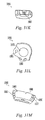
- FIG. 7A shows an oblong captive clip for use with the plate of FIG. 5A ;
- FIG. 7B shows a cross-sectional view taken along line VIIB-VIIB of the circular captive clip of FIG. 7A ;
- FIG. 8A shows a perspective view of an embodiment of a self-drilling fastener
- FIG. 8B shows a side view of the fastener of FIG. 8A ;
- FIG. 8C shows a partial cross-sectional side view taken along line VIIIC-VIIIC of the fastener of FIG. 8B ;
- FIG. 8D shows a partial side view of the head of the fastener of FIG. 8A ;
- FIG. BE shows a top view of the fastener of FIG. 8A ;
- FIG. 8F shows a bottom view of the fastener of FIG. 8A ;
- FIG. 8G shows a partial cross-sectional side view of the shaft and threads of the fastener of FIG. 8A ;
- FIG. 9A shows a top view of a plate for use with a third embodiment of a fixation system
- FIG. 9B shows a partial cross-sectional view taken along line IXB-IXB of the plate of FIG. 9A ;
- FIG. 9C shows a top view of end 221 a of the plate of FIG. 9A ;
- FIG. 9D shows a top view of end 221 b of the plate of FIG. 9A ;
- FIG. 9E shows a partial cross-sectional view taken along line IXE-IXE of the plate of FIG. 9B ;
- FIG. 9F shows a partial cross-sectional view taken along line IXF-IXF of the plate of FIG. 9E ;
- FIG. 9G shows another partial cross-sectional view taken along line IXF-IXF of the plate of FIG. 9E ;
- FIG. 10A shows a captive clip for use with the plate of FIG. 9A ;
- FIG. 10B shows a cross-sectional view taken along line XB-XB of the captive clip of FIG. 10A ;
- FIG. 11 shows a perspective view of another plate with fasteners installed therewith along with the captive clip of FIG. 10A ;
- FIG. 12 shows an alternate captive clip for use with the plate of FIG. 9A or 11 ;
- FIG. 13 shows a partial cross-sectional side view of the captive clip of FIG. 12 installed in the plate of FIG. 11 ;
- FIG. 14 shows another alternate captive clip
- FIG. 15 shows yet another alternate captive clip
- FIG. 16A shows a bottom perspective view of a plate and cam element used in a fourth embodiment of a fixation system
- FIG. 16B shows a partial cross-sectional perspective view of the plate and cam element of FIG. 16A with the cam element in a locked position with respect to a captive clip;
- FIG. 16C shows a bottom view of the plate and cam element of FIG. 16A with the cam element in an unlocked position with respect to a captive clip
- FIG. 16D shows a bottom view of the plate and cam element of FIG. 16A with the cam element in a locked position with respect to a captive clip
- FIG. 17A shows a top view of a plate for use with a fifth embodiment of a fixation system
- FIG. 17B shows a partial cross-sectional view taken along line XVIIB-XVIIB of the plate of FIG. 17A ;
- FIG. 17C shows a partial cross-sectional view taken along line XVIIC-XVIIC of the plate of FIG. 17B ;
- FIG. 17D shows a partial cross-sectional view taken along line XVIID-XVIID of the plate of FIG. 17C ;
- FIG. 17E shows another partial cross-sectional view taken along line XVIID-XVIID of the plate of FIG. 17C ;
- FIG. 18A shows a captive clip for use with the plate of FIG. 17A ;
- FIG. 18B shows a cross-sectional view taken along line XVIIIB-XVIIIB of the captive clip of FIG. 18A ;
- FIG. 19A shows a perspective view of another embodiment of a fastener
- FIG. 19B shows a side view of the fastener of FIG. 19A ;
- FIG. 19C shows a partial cross-sectional side view taken along line XIXC-XIXC of the fastener of FIG. 19B ;
- FIG. 19D shows a partial side view of the head of the fastener of FIG. 19A ;
- FIG. 19E shows a top view of the fastener of FIG. 19A ;
- FIG. 19F shows a bottom view of the fastener of FIG. 19A ;
- FIG. 19G shows a partial cross-sectional side view of the shaft and threads of the fastener of FIG. 19A ;
- FIG. 20A shows a schematic of the captive clip of FIG. 18A in an unexpanded state with a cross-section of a screw head inserted through the clip;
- FIG. 20B shows a schematic of the captive clip of FIG. 18A in an expanded state with a cross-section of a screw head inserted through the clip;
- FIG. 21A shows a top view of a plate for use with a sixth embodiment of a fixation system
- FIG. 21B shows a partial cross-sectional view taken along line XXIB-XXIB of the plate of FIG. 21A ;
- FIG. 21C shows a partial cross-sectional view taken along line XXIC-XXIC of the plate of FIG. 21B ;
- FIG. 21D shows a partial cross-sectional view taken along line XXID-XXID of the plate of FIG. 21C ;
- FIG. 21E shows another partial cross-sectional view taken along line XXID-XXID of the plate of FIG. 21C ;
- FIG. 22 shows a partial cross-sectional perspective view of the plate of FIG. 21A with a fastener and captive clip installed therein;
- FIG. 23A shows a top view of a one level plate for use with a seventh embodiment
- FIG. 23B shows a partial cross-sectional side view taken along line XXIIIB-XXIIIB of the plate FIG. 23A ;
- FIG. 24A shows a top view of a two level plate for use with a seventh embodiment
- FIG. 24B shows a partial cross-sectional side view taken along line XXIVB-XXIVB of the plate FIG. 24A ;
- FIG. 25A shows a top view of a three level plate for use with a seventh embodiment
- FIG. 25B shows a partial cross-sectional side view taken along line XXVB-XXVB of the plate FIG. 25A ;
- FIG. 26A shows a top view of a four level plate for use with a seventh embodiment
- FIG. 26B shows a partial cross-sectional side view taken along line XXVIB-XXVIB of the plate FIG. 26A ;
- FIG. 27A shows a cross-sectional view taken along line XXVIIA-XXVIIA of the plate of FIG. 23B ;
- FIG. 27B shows a partial bottom view of a fixation hole and passage of the plate of FIG. 23A ;
- FIG. 27C shows a partial side view of a portion of the slot of the plate as indicated at detail N in FIG. 23B ;
- FIG. 27D shows a cross-sectional side view taken along line XXVIID-XXVIID of the plate of FIG. 23B ;
- FIG. 27E shows another cross-sectional side view of one of the fixation holes taken along line XXVIID-XXVIID of the plate of FIG. 23B ;
- FIG. 28A shows a captive clip for use with the plates of FIGS. 23A, 24A, 25A, and 26A ;
- FIG. 28B shows a cross-sectional view taken along line XXVIIIB-XXVIIIB of the captive clip of FIG. 28A ;
- FIG. 29 shows a partial cross-sectional perspective view of the plate of FIGS. 23A, 24A, 25A, and 26A with a fastener and the captive clip of FIG. 28A installed therein;
- FIG. 30A shows another embodiment of a captive clip
- FIG. 30B shows a cross-sectional view taken along line XXXB-XXXB of the captive clip of FIG. 30A ;
- FIG. 30C shows another view of the captive clip of FIG. 30A along with a cross-section of a fastener head taken along the minor diameter of a perimetral groove in the fastener head;
- FIG. 31A shows a perspective view of a four level plate for use with an eighth embodiment
- FIG. 31B shows a partial perspective view of the plate of FIG. 31A with captive clips and a fastener installed therein;
- FIG. 31C shows a partial cross-sectional perspective view of the plate of FIG. 31A with a captive clip and a fastener installed therein;
- FIG. 31D shows another partial cross-sectional perspective view of the plate of FIG. 31A with captive clips and fasteners installed therein;
- FIG. 31E shows a top view of another embodiment of a plate
- FIG. 31F shows a partial cross-sectional side view of the plate of FIG. 31E ;
- FIG. 31G shows a cross-sectional view taken along line XXXIG-XXXIG of the plate of FIG. 31E ;
- FIG. 31H shows a cross-sectional view taken along line XXXIH-XXXIH of the plate of FIG. 31E ;
- FIG. 31I shows a cross-sectional view taken along line XXXII-XXXII of the plate of FIG. 31E ;
- FIG. 31J shows a cross-sectional view of a keyhole-shaped fixation hole of the plate of FIG. 31E taken in the circular portion of the fixation hole along line XXXIG-XXXIG;
- FIG. 31K shows a partial cross-sectional side view taken along the midline 1084 of the plate of FIG. 31E proximate a circular fixation hole;
- FIG. 31L shows a partial bottom view of a circular fixation hole of the plate of FIG. 31E ;
- FIG. 31M shows a partial cross-sectional side view of a keyhole-shaped fixation hole of the plate of FIG. 31E taken in the straight portion of the fixation hole along line XXXIH-XXXIH;
- FIG. 31N shows a top view of another multi-level fixation plate
- FIG. 31O shows a top view of another embodiment of a captive clip
- FIG. 31P shows a cross-sectional side view taken along line XXXP-XXXP of the plate of FIG. 31E ;
- FIG. 32A shows a side view of an embodiment of a variable angle, self-tapping fastener
- FIG. 32B shows a partial cross-sectional side view taken along line XXXIIB-XXXIIB of the fastener of FIG. 32A ;
- FIG. 32C shows a partial side view of the head of the fastener of FIG. 32A ;
- FIG. 32D shows a top view of the fastener of FIG. 32A ;
- FIG. 32E shows a partial cross-sectional side view of the shaft and threads of the fastener of FIG. 32A configured and dimensioned for use with cancellous bone;
- FIG. 32F shows another partial cross-sectional side view of the shaft and threads of the fastener of FIG. 32A configured and dimensioned for use with cortical bone;
- FIG. 33A shows a side view of an embodiment of a variable angle, self-drilling fastener
- FIG. 33B shows a partial cross-sectional side view taken along line XXXIIIB-XXXIIIB of the fastener of FIG. 33A ;
- FIG. 33C shows a partial side view of the head of the fastener of FIG. 33A ;
- FIG. 33D shows a top view of the fastener of FIG. 33A ;
- FIG. 34A shows a side view of an embodiment of a fixed angle, self-tapping fastener
- FIG. 34B shows a partial cross-sectional side view taken along line XXXIVB-XXXIVB of the fastener of FIG. 34A ;
- FIG. 34C shows a partial side view of a fixed-angle head of the fastener of FIG. 34A ;
- FIG. 34D shows a top view of the fastener of FIG. 34A ;
- FIG. 34E shows a partial cross-sectional side view taken along line XXXIVF-XXXIVF of the fastener of FIG. 34A ;
- FIG. 35A shows aside view of an embodiment of a fixed angle, self-drilling fastener
- FIG. 35B shows a partial cross-sectional side view taken along line XXXVB-XXXVB of the fastener of FIG. 35A ;
- FIG. 35C shows a partial side view of the head of the fastener of FIG. 35A ;
- FIG. 35D shows a top view of the fastener of FIG. 35A ;
- FIG. 35E shows a partial cross-sectional side view taken along line XXXVF-XXXVF of the fastener of FIG. 35A ;
- FIG. 36A shows a first perspective view of an embodiment of a plate having a fastener with scallops installed therewith;
- FIG. 36B shows another perspective view of the embodiment of FIG. 36A ;
- FIG. 36C shows another perspective view of the embodiment of FIG. 36A ;
- FIG. 36D shows another perspective view of the embodiment of FIG. 36A ;
- FIG. 37A shows a side view of an embodiment of a fastener
- FIG. 37B shows a partial cross-sectional side view taken along line XXXVIIB-XXXVIIB of the fastener of FIG. 37A ;
- FIG. 37C shows a partial side view of the head of the fastener of FIG. 37A ;
- FIG. 37D shows a partial cross-sectional side view taken along line XXXVIID-XXXVIID of the fastener of FIG. 37E ;
- FIG. 37E shows a top view of the fastener of FIG. 37A ;
- FIG. 37F shows a partial top view of the fastener of FIG. 37A
- FIG. 37G shows a partial side view of area S of FIG. 37C ;
- FIG. 37H shows an alternate a top view of the fastener of FIG. 37A ;
- FIG. 37I shows an alternate partial top view of the fastener of FIG. 37A ;
- FIG. 38A shows a perspective view of an embodiment of a plate having gussets
- FIG. 38B shows a top view of the plate of FIG. 38A ;
- FIG. 38C shows a cross-sectional side view taken along line XXXVIIIC-XXXVIIIC of the plate of FIG. 38A ;
- FIG. 38D shows a cross-sectional side view taken along line XXXVIIID-XXXVIIID of the plate of FIG. 38A , with a fastener disposed in a hole in the plate;
- FIG. 38E shows a perspective view of an embodiment of a fastener with slits
- FIG. 38F shows a cross-sectional side view of the fastener of FIG. 38E with a fastener head in an expanded state
- FIG. 38G shows a cross-sectional side view of the fastener of FIG. 38E with a fastener head in a contracted state as being inserted or removed from the plate;
- FIG. 39A shows a perspective view of another embodiment of a fixation system
- FIG. 39B shows a top view of the plate of the fixation system shown in FIG. 39A ;
- FIG. 39C shows a side view of the plate of FIG. 39B ;
- FIG. 39D shows a cross-sectional view of the plate of FIG. 39C taken along the line X 39 -X 39 ;
- FIG. 40 shows a top view of an embodiment of a clip
- FIG. 41A shows a side view of an exemplary variable-angle screw
- FIG. 418 shows a side view of an exemplary fixed-angle screw
- FIG. 42A shows a partially-removed cross-sectional view of a variable-angle screw engaging a plate
- FIG. 42B shows a partially-removed cross-sectional view of a fixed-angle screw engaging a plate
- FIG. 43A shows a side view of an exemplary variable-angle drill guide for use with the system of FIG. 39A ;
- FIG. 43B shows a cross-sectional view of the barrel of the drill guide of FIG. 43A ;
- FIG. 43C shows an enlarged partial cross-sectional view of the tip portion of the drill guide of FIG. 43A ;
- FIG. 44A shows a side view of an exemplary fixed-angle drill guide for use with the system of FIG. 39A ;
- FIG. 44B shows a cross-sectional view of the barrel of the drill guide of FIG. 44A ;
- FIG. 44C shows an enlarged partial cross-sectional view of the tip portion of the drill guide of FIG. 44A ;
- FIG. 44D shows a partially-removed cross-sectional view of a fixed-angle drill guide engaging a plate.
- the fixation system includes a plate 20 with two pairs of fixation holes 22 , 24 .
- Fixation holes 22 are oblong in shape so as to have a different length than width (i.e., the hole is non-circular), while fixation holes 24 are circular in shape.
- the fixation holes are preferably oblong in the direction along the longitudinal axis 28 a of the bone plate 20 .
- plate 20 is provided with two pairs of fixation holes 22 , 24 , more than two pairs may instead be provided, for example so that plate 20 may span a greater length and thus be fastened to multiple locations along the spine.
- Single holes alternatively may be provided as opposed to pairs.
- a slot 26 is aligned along central longitudinal axis 28 a for receiving a drill/screw guide and for graft visualization.
- slot 26 does not receive any fasteners.
- more than one slot may be provided, and the slot or slots may be disposed transverse to central longitudinal axis 28 a .
- slot 26 includes straight portions 26 a and semicircular portions 26 b.
- Each of fixation holes 22 , 24 extends between top and bottom surfaces 28 , 30 and includes an undercut 32 .
- undercut 32 is disposed closer to top surface 28 than bottom surface 30 while in another embodiment, undercut 32 is disposed closer to bottom surface 30 than top surface 28 .
- Undercut 32 also may be disposed intermediate top and bottom surfaces 28 , 30 , or transverse to the surfaces.
- an undercut 32 extends completely around each of fixation holes 22 , 24 .
- a lower portion 34 of each fixation hole 22 , 24 may be disposed between bottom surface 28 and undercut 32 and may taper toward a central axis 36 of the respective fixation hole as shown for example in FIG. 1D .
- lower portion 34 has a first maximum inner dimension L 1 and the undercut has a second maximum inner dimension L 2 , wherein the first maximum inner dimension L 1 is less than the second maximum inner dimension L 2 .
- FIGS. 2A and 2B a generally circular captive clip 50 is shown with a slit 52 that permits elastic expansion/compression of clip 50 as will be explained shortly, as well as an outer edge 54 and an inner edge 56 .
- Clip 50 includes a generally rectangular cross-section, and in one embodiment, is provided with a radius R 1 adjoining outer edge 54 of about 0.1 mm and a second radius R 2 adjoining inner edge 56 of about 0.2 mm.
- plate 20 is shown with a fastener 60 in each of fixation holes 22 , 24 .
- a captive clip 50 is provided for each fastener 60 around head 62 .
- a clip 50 is pre-installed in each fixation hole 22 , 24 , and snap-fits around a head 62 of a fastener 60 such that post-operative back-out of a fastener 60 from a hole 22 , 24 is resisted.
- a captive clip 50 disposed in an undercut 32 of an elongated, oblong hole 22 is permitted to travel (slide) along a longitudinal axis 22 a of the hole, as shown in FIGS. 1A and 1E .
- a fastener 60 on a captive clip 50 and disposed in an oblong hole 22 can slide across the length of hole 22 .
- a captive clip 50 disposed in an undercut 32 of a circular hole 24 is not permitted to travel (slide) along a longitudinal axis 24 a of hole 24 , a shown in FIGS. 1A and 1D .
- fasteners As will be described in detail herein, various embodiments of fasteners are contemplated. In particular, two main types of fasteners for “variable angle” and “fixed angle” applications are provided.
- “Variable angle” refers to fasteners and/or plates for which: (1) the trajectory of insertion of the fastener into bone (through a fixation hole in the plate) may be selected by the surgeon (although only a limited range of motion may be permitted); and/or (2) the trajectory of the fastener with respect to the plate is allowed to change following insertion into bone, for example to toggle to accommodate any translational and/or rotational settling that occur post-operatively between the plate and the fastener that has been rigidly placed into a vertebral body (although only a limited range of motion may be permitted).
- “Fixed angle” refers to fasteners and/or plates for which: (1) the trajectory of insertion of the fastener into bone (through a fixation hole in the plate) is pre-selected and thus fixed; and/or (2) the trajectory of the fastener with respect to the plate is not allowed to change following insertion into bone.
- Each of the two main types of fasteners may be provided with features for use preferably with either cancellous or cortical bone. Moreover, each of the two main types of fasteners may be provided preferably with either self-tapping or self-drilling features. Finally, the diameters of the fasteners may be varied as well as the lengths. In selecting a fastener for a given application, therefore, a surgeon must decide which type of fastener and which combination of features are appropriate.
- variable-angle, cancellous, self-tapping variable-angle, cancellous, self-drilling
- variable-angle, cortical, self-tapping variable-angle, cortical, self-tapping
- variable-angle, cortical, self-drilling variable-angle, cortical, self-drilling
- fixed-angle, cancellous, self-tapping (6) fixed-angle, cancellous, self-drilling
- fixed-angle, cortical, self-tapping fixed-angle, cortical, self-tapping
- (8) fixed-angle, cortical, self-drilling fixed-angle, cortical, self-drilling.
- an exemplar fastener 60 includes a head 62 with a self-tapping, threaded shaft 64 with a flute 65 provided proximate the bottom of the threading.
- Head 62 includes a perimetral groove 66 extending around at least a portion thereof, and an instrument receiving portion 68 that at least partially intersects groove 66 at one or more openings 70 .
- Instrument receiving portion 68 preferably includes an internal, unthreaded, cylindrical, annular wall 69 , although in an alternate embodiment wall 69 may be threaded.
- FIG. 1 In the exemplar embodiment of FIG.
- instrument receiving portion 68 is cross-shaped and thus intersects groove 66 at four openings 70 .
- a pair of slots 70 a , 70 b (similar to the look of a Phillips-head screw) form instrument receiving portion 68 .
- Fastener 60 preferably is used with a plate 20 such that fastener 62 may toggle in the fixation holes.
- fastener 60 preferably is used for fixation to cancellous bone.
- threading appropriate for cortical bone instead may be provided.
- perimetral groove 66 includes an upper surface 66 a and a lower surface 66 b disposed at an angle ⁇ of between about 10° and about 70° with respect to each other. More preferably, upper surface 66 a and lower surface 66 b are disposed at an angle ⁇ of between about 30° and about 50° with respect to each other, and most preferably, they are an angle ⁇ of about 40° with respect to each other. The angulation of surfaces 66 a , 66 b with respect to each other permits toggling of fastener 60 when coupled to a captive clip 50 .
- Head 62 preferably is partially spherical and includes a bottom section 68 extending to the top end 70 of shaft 64 , with bottom section 68 tapering inward toward longitudinal axis 72 from perimetral groove 66 to top end 70 .
- such tapering permits angulation of fastener 60 when disposed in a fixation hole 22 , 24 .
- a fastener 60 is received in a captive clip 50 .
- the shaft 64 is initially screwed into bone until the partial-spherical head 62 of fastener 60 reaches captive clip 50 .
- the partial-spherical head 62 particularly bottom section 68 , bears against the inside edge 56 of captive clip 50 and expands captive clip 50 .
- captive clip 50 contracts so that it “snaps” into perimetral groove 66 in head 62 , thereby preventing fastener 60 from backing out of plate 20 , as previously described.
- captive clip 50 subsequently may be elastically expanded to permit removal of fastener 60 .
- the screwdriver tip When a screwdriver tip is inserted in the slots 70 a , 70 b of instrument receiving portion 68 , the screwdriver tip protrudes into the perimetral groove 66 through openings 70 . Inserting the screwdriver tip thus elastically expands captive clip 50 to allow fastener 60 to be unscrewed from bone without interference from captive clip 50 .
- FIGS. 5A-8G A second embodiment of a fixation system is shown in FIGS. 5A-8G .
- the fixation system includes a plate 120 with two pairs of fixation holes 122 , 124 .
- Fixation holes 122 are oblong in shape so as to have a different length than width (i.e., the hole is non-circular), while fixation holes 124 are circular in shape.
- plate 120 is provided with two pairs of fixation holes 122 , 124 , more than two pairs may instead be provided, for example so that plate 120 may span a greater length and thus be fastened to multiple locations along the spine.
- Plate 120 is not provided with a slot for receiving a drill/screw guide or for graft visualization. However, in alternate embodiments, one or more slots may be provided, and the slot or slots may be disposed transverse to central longitudinal axis 128 a.
- Each of fixation holes 122 , 124 extends between top and bottom surfaces 128 , 130 and includes an undercut 132 .
- undercut 132 is disposed closer to top surface 128 than bottom surface 130 while in another embodiment, undercut 132 is disposed closer to bottom surface 130 than top surface 128 .
- Undercut 132 also may be disposed intermediate top and bottom surfaces 128 , 130 , or transverse to the surfaces.
- an undercut 132 extends completely around each of fixation holes 122 , 124 .
- a lower portion 134 of each fixation hole 122 , 124 may be disposed between bottom surface 128 and undercut 132 .
- Lower portion 134 optionally may taper toward a central axis 136 of the respective fixation hole as shown for example in FIG. 5D .
- lower portion 134 has a first maximum inner dimension L 3 and the undercut has a second maximum inner dimension L 4 , wherein the first maximum inner dimension L 3 is less than the second maximum inner dimension L 4 .
- Plate 120 may be provided with two types of captive clips.
- a circular captive clip 150 a is shown in FIGS. 6A and 6B with a slit 152 a that permits elastic expansion/compression of clip 150 a as previously explained, as well as an outer edge 154 a and an inner edge 156 a .
- Clip 150 a includes a generally rectangular cross-section, and in one embodiment, is provided with a radius R 3 on outer edge 154 a of about 0.1 mm and a second radius R 4 on inner edge 156 a of about 0.2 mm.
- ends 158 a , 159 a forming slit 152 a of clip 150 a preferably are angled at between about 5° and about 15° with respect to each other, and more preferably at about 10°.
- Clip 150 a is sized to be received in fixation hole 124 .
- an oblong captive clip 150 b is shown in FIGS. 7A and 7B with a slit 152 b that permits elastic expansion/compression of clip 150 b as previously explained, as well as an outer edge 154 b and an inner edge 156 b .
- Clip 150 b includes a generally rectangular cross-section, and in one embodiment, is provided with a radius R 5 at outer edge 154 b of about 0.1 mm and a second radius R 6 at inner edge 156 b of about 0.2 mm. Clip 150 b is sized to be received in a fixation hole 122 . In a relaxed state, ends 158 b , 159 b forming slit 152 b of clip 150 b preferably are angled at between about 5° and about 15° with respect to each other, and more preferably at about 10°.
- a captive clip 150 a or 150 b is provided for each fastener 160 around head 162 , based on whether the fastener 160 is disposed in an oblong fixation hole 122 or a circular fixation hole 124 .
- a clip 150 is pre-installed in each fixation hole 122 , 124 , and snap-fits around at least part of a head 162 of a fastener 160 during installation of the fastener such that post-operative back-out of a fastener 160 from a hole 122 , 124 is resisted.
- captive clip 150 b when a captive clip 150 b is disposed in undercut 132 of elongated, oblong hole 122 , captive clip 150 b serves as a rail upon which a fastener 160 is permitted to travel (slide) along a longitudinal axis 122 b of the hole.
- a fastener 160 on a captive clip 150 b and disposed in an oblong hole 122 can slide across the length of the hole.
- neither captive clip 150 a disposed in an undercut 132 of a circular hole 124 nor a fastener captured by the captive clip 150 a , is permitted to travel (slide) along a longitudinal axis 124 a of the hole.
- an exemplar fastener 160 includes a head 162 with a self-drilling, threaded shaft 164 .
- Head 152 includes a perimetral groove 166 extending around at least a portion thereof, and an instrument receiving portion 168 .
- instrument receiving portion 168 is not shown to at least partially intersect groove 166 at one or more openings, provision for such may be made as described previously.
- instrument receiving portion 168 is hexagonal-shaped. However, in alternate embodiments, other shapes may be provided.
- Fastener 160 preferably is used with a plate 120 such that fastener 160 may toggle in the fixation holes.
- fastener 160 preferably is used for fixation to cancellous bone.
- perimetral groove 166 includes an upper surface 166 a and a lower surface 166 b that are disposed at between about 5° and about 50° with respect to each other.
- upper surface 166 a is disposed at an angle ⁇ 1 of between about 5° and about 15° with respect to a line 173 disposed approximately intermediate upper inside edge 173 and lower inside edge 173 b and perpendicular to longitudinal axis 172 .
- angle ⁇ 1 is about 10°.
- lower surface 166 b preferably is disposed at an angle ⁇ 2 of between about 15° and about 35° with respect to line 173 .
- angle ⁇ 2 is about 25°.
- angles ⁇ 1 , ⁇ 2 total about 35°.
- the angulation of surfaces 166 a , 166 b with respect to each other permits toggling of fastener 160 when coupled to a captive clip 150 a , 150 b.
- Head 162 preferably is partially spherical and includes a bottom section 168 extending to the top 170 of shaft 164 , with bottom section 168 tapering inward toward longitudinal axis 172 from perimetral groove 166 to top 170 .
- such tapering permits angulation of fastener 160 when disposed in a fixation hole 122 , 124 .
- a fastener 160 is received in a captive clip 150 a or 150 b .
- the shaft 164 is initially screwed into bone until the partial-spherical head 162 of fastener 160 reaches captive clip 150 a or 150 b .
- the partial-spherical head 162 particularly bottom section 168 , bears against the inside edge 156 a , 156 b of captive clip 150 a , 150 b , respectively, and expands the clip.
- captive clip 150 a or 150 b contracts so that it “snaps” into perimetral groove 166 in head 162 , thereby preventing fastener 160 from backing out of plate 120 , as previously described.
- FIGS. 9A-12 A third embodiment of a fixation system is shown in FIGS. 9A-12 .
- the fixation system includes a plate 220 with two pairs of fixation holes 222 , 224 .
- Fixation holes 222 are oblong in shape, while fixation holes 224 are circular in shape.
- plate 220 is provided with two pairs of fixation holes 222 , 224 , more than two pairs may instead be provided, for example so that plate 220 may span a greater length and thus be fastened to multiple locations along the spine.
- a slot 226 is aligned along central longitudinal axis 228 a for receiving a drill/screw guide and for graft visualization.
- slot 226 does not receive any fasteners.
- more than one slot may be provided, and the slot or slots may be disposed transverse to central longitudinal axis 228 a .
- slot 226 includes straight portions 226 a and semicircular portions 226 b.
- Each of fixation holes 222 , 224 extends between top and bottom surfaces 228 , 230 . As shown in particular in FIGS. 9C and 9D , each pair of the fixation holes is partially intersected by a common slot 232 .
- captive clip 250 is elastically flexible to permit expansion and contraction, although such flexibility is not necessary.
- Clip 250 has an outer edge 254 and an inner edge 256 .
- Clip 250 also has a generally rectangular cross-section, and in one embodiment, has flat upper and lower surfaces 258 a , 258 b , as well as rounded sides 259 a , 259 b.
- each pair of fixation holes 224 is partially intersected by a common slot 232 .
- a captive clip 250 is inserted into each slot 232 , and is sized such that it protrudes into each fixation hole 224 .
- a clip 250 is pre-installed in each slot 232 .
- a fastener such as one of the fasteners previously described with a perimetral groove in its head
- captive clip 250 bears against the perimetral groove, thereby locking the fastener in place and preventing the fastener from backing out of plate 220 b .
- a captive clip 250 may be removed from either the cephalad or caudal side of plate 220 b where the fastener is located, thereby unlocking that fastener from plate 220 b .
- Plate 220 b is similar to plate 220 as shown in FIGS. 9A-9G , with a clip 250 assembled therewith.
- FIGS. 12-13 An alternate embodiment of a clip 270 is shown in FIGS. 12-13 .
- Clip 270 is generally shaped like a paper clip, and thus may confer spring-like behavior.
- clip 270 may be inserted in, and/or removed from, a slot 232 from either the cephalad or caudal side of plate 220 b .
- a first end 272 of clip 270 is arcuate, while a second end 274 is straight.
- Second end 274 is straight for stability, and preferably is disposed toward the outer edge of the plate. In some embodiments, one or more edge surfaces may be straight to allow for a flush resting surface with a greater surface area for abutting a surface of a plate in which clip 270 is installed. Two free ends 279 a , 279 b may be provided.
- FIGS. 14 and 15 Additional alternate embodiments of captive clips are shown in FIGS. 14 and 15 .
- a clip 280 shown in FIG. 14 , includes a slit 282 that permits elastic expansion/compression of clip 280 as previously explained.
- Clip 280 has an outer edge 284 and an inner edge 286 .
- Clip 290 as shown in FIG. 15 , includes a slit 292 that permits elastic expansion/compression, an outer edge 294 , an inner edge 296 , and further includes opposing recesses 298 the potential use of which will be explained below.
- Captive clip 290 further includes a pair of generally parallel sides 299 a , 299 b.
- FIGS. 16A-16D a fourth embodiment of a fixation system is shown.
- the fixation system includes a plate 320 with two pairs of circular fixation holes 222 (only one pair is shown in FIG. 16A ).
- a slot 326 is aligned along central longitudinal axis 328 a for receiving a drill/screw guide and for graft visualization. Preferably, slot 326 does not receive any fasteners.
- Each of fixation holes 322 extends between top and bottom surfaces 328 , 330 .
- Each pair of fixation holes 322 is partially intersected by a common slot 332 . As shown in each of FIGS.
- a captive clip 290 is inserted in slot 332 from a side, preferably cephalad or caudal, of plate 320 .
- slot 332 is disposed transverse to central longitudinal axis 328 a and such that it opens on a side of plate 320 , preferably the cephalad and/or caudal sides.
- slot 332 alternatively may open on a side of plate 320 that extends between the cephalad and caudal sides of plate 320 .
- a cam element 334 is inserted from the bottom 330 of plate 320 , and is received in recesses 298 of captive clip 290 to govern expansion and contraction thereof.
- Cam element 334 is turned using a locking screw 336 fastened thereto.
- FIGS. 16A and 16C captive clip 290 can freely expand and contract, and thus a fastener is not captured as securely by the clip.
- FIGS. 168 and 16D cam element 334 engages recesses 298 , and thus compression of captive clip 290 is prevented by cam element 334 thereby permitting captive clip 290 to securely capture one or more fasteners inserted in fixation holes 322 .
- cam element 334 has four rounded corners to facilitate engagement with recesses 298 .
- the fixation system includes a plate 420 with two pairs of fixation holes 422 , 424 .
- Fixation holes 422 , 424 are circular in shape.
- plate 420 is provided with two pairs of fixation holes 422 , 424 , more than two pairs may instead be provided, for example so that plate 420 may span a greater length and thus be fastened to multiple locations along the spine.
- a “dogbone” shaped slot 426 is aligned along central longitudinal axis 427 for receiving a drill/screw guide and for graft visualization. Preferably, slot 426 does not receive any fasteners.
- Each of fixation holes 422 , 424 extends between top and bottom surfaces 428 , 430 and includes an undercut 432 .
- undercut 432 is disposed transverse to top and bottom surfaces 428 , 430 , respectively, along line 432 a , but other orientations are also possible as previously described with respect to other embodiments.
- an undercut 432 extends completely around each of fixation holes 422 , 424 .
- At least one passage 429 extends transverse to each of the fixation holes 422 , 424 , preferably from bottom surface 428 , and intersects an undercut 432 associated with the hole 422 or 424 . Passages 429 are used for alignment of captive clips, as will be described shortly.
- FIGS. 18A and 18B a generally U-shaped captive clip 450 is shown with a slit 452 that permits elastic expansion/compression of clip 450 , as well as an outer edge 454 , an inner edge 456 , and generally parallel sides 459 a , 459 b .
- Clip 450 includes a generally rectangular cross-section, and in one embodiment, is provided with a radius R 7 at edges 454 and 456 of between about 0.1 mm and about 0.2 mm.
- An end tab 458 extends from side 459 a , preferably transverse to the plane of the page. In some embodiments, end tab 458 extends generally parallel to the plane of the page.
- end tab 458 extends into a passage 429 so that captive clip 450 may be aligned and properly placed in undercut 432 in the fixation hole.
- captive clips 450 are pre-installed in fixation holes 422 , 424 in plate 420 prior to installation of fasteners therein.
- a captive clip 450 is provided for each fastener 460 around head 462 .
- clip 450 snap-fits around head 462 of a fastener 460 such that post-operative back-out of a fastener 460 from a hole 422 , 424 is resisted.
- a fastener 460 retained on a captive clip 450 disposed in an undercut 432 of a circular hole 422 , 424 may be permitted to toggle along a central axis of the hole.
- an exemplar fastener 460 includes a head 462 with a self-tapping, threaded shaft 464 .
- a self-drilling, threaded shaft 464 may be provided.
- Head 462 includes a perimetral groove 466 that is interrupted by four corners 470 separating back wall 471 .
- an instrument receiving portion 468 is hexagonal-shaped. However, in alternate embodiments, other shapes may be provided.
- Fastener 460 preferably is used for fixation to cancellous bone, although threading appropriate for fixation to cortical bone instead may be provided.
- perimetral groove 466 includes an upper portion 466 a and a lower portion 466 b that are disposed generally parallel to each other.
- Head 462 preferably is partially spherical and includes a bottom section 475 extending to the top end 473 of shaft 464 , with bottom section 475 tapering inward toward longitudinal axis 472 from perimetral groove 466 to top end 473 .
- such tapering permits angulation of fastener 460 when disposed in a fixation hole 422 , 424 .
- fastener 460 is received in captive clip 450 .
- the shaft 464 is initially screwed into bone until the partial-spherical head 462 of fastener 460 reaches captive clip 450 .
- the partial-spherical head 462 particularly bottom section 475 , bears against the inside edge 456 of captive clip 450 and expands captive clip 450 .
- captive clip 450 contracts so that it “snaps” into perimetral groove 466 in head 462 , thereby preventing fastener 460 from backing out of plate 420 , as previously described.
- the four corners 470 of fastener 460 may be retained on captive clip 450 while the clip is in an unexpanded state.
- two of the corners act as cams on the inner wall 456 of the clip to elastically expand it such that the fastener is no longer locked by captive clip 450 .
- it is possible to remove a fastener by turning the fastener to engage the cams with the clip to expand the clip.
- a fastener 460 retained on captive clip 450 , can toggle on captive clip 450 in a fixation hole 422 , 424 , because of the geometry of the perimetral groove 466 in head 462 of fastener 460 and the geometry of the fixation hole 422 , 424 .
- captive clip 450 remains essentially fixed in place, while the axis of fastener 460 is allowed to angulate with respect to the central axis of the fixation hole 422 , 424 .
- surfaces 466 a , 466 b of groove 466 are generally parallel to each other, toggling may be substantially limited.
- FIGS. 21A-22 A sixth embodiment of a fixation system is shown in FIGS. 21A-22 .
- the fixation system includes a plate 520 with two pairs of fixation holes 522 , 524 .
- Fixation holes 522 , 524 are circular in shape.
- plate 520 is provided with two pairs of fixation holes 522 , 524 , more than two pairs may instead be provided, for example so that plate 520 may span a greater length and thus be fastened to multiple locations along the spine.
- no slot is provided along central longitudinal axis 528 a for receiving a drill/screw guide and for graft visualization, one may be provided as described previously with respect to other embodiments.
- Each of fixation holes 522 , 524 extends between top and bottom surfaces 528 , 530 , respectively, and includes an undercut 532 .
- undercut 532 is disposed transverse to top and bottom surfaces 528 , 530 , respectively, but other orientations are also possible as previously described with respect to other embodiments.
- an undercut 532 extends completely around each of fixation holes 522 , 524 .
- the geometry of one pair of fixation holes 522 is sized such that movement of a fastener 560 therein is very limited.
- the geometry of the remaining pair of fixation holes 524 allows a fastener 560 to toggle between about 5° and about 30°, and more preferably between about 15° and about 20°, as shown in FIG. 22 .
- a fastener 560 shown in FIG. 22 , is retained on a captive clip 550 .
- the fastener 560 may toggle on captive clip 550 in fixation hole 524 because of the geometry of perimetral groove 566 in the head 562 of the fastener and the geometry of fixation hole 524 .
- lower portion 534 a widens proximate bottom surface 530 of plate 520 .
- the captive clip 550 preferably remains fixed in place, while the axis of fastener 560 is allowed to angulate with respect to the axis of fixation hole 524 .
- Plates 620 , 720 , 820 , 920 represent “one level,” “two level,” “Three level,” and “four level” constructions, respectively.
- Each “level” is provided by one or more fixation holes, and preferably pairs of adjacent fixation holes, bridging two vertebrae.
- a first level plate bridges two vertebrae and includes at least one fixation hole, preferably two adjacent fixation holes for each vertebrae, while a second level plate bridges three vertebrae and includes at least one fixation hole, preferably two adjacent fixation holes for each vertebrae.
- plate 620 has two pairs of fixation holes 622 , 624 , and thus only represents one level; in contrast, plate 720 has three pairs of fixation holes, and thus the middle pair of fixation holes is adjacent two other pairs thus forming a two level construction.
- plates 620 , 720 , 820 , 920 are very similar, and thus although plate 620 will be described in detail herein, the description of plate 620 applies also to plates 720 , 820 , 920 .
- the fixation system includes a plate 620 with two pairs of fixation holes 622 , 624 .
- Fixation holes 622 , 624 are circular in shape.
- a “figure eight” shaped slot 626 is aligned along central longitudinal axis 628 a for receiving a drill/screw guide and for graft visualization.
- slot 626 does not receive any fasteners, and is beveled along upper inner edge 626 a at an angle ⁇ between about 30° and about 60°, and more preferable about 45°.
- slot 626 becomes elongated and generally “dog-bone” shaped as shown for example in FIGS. 25A and 26A .
- Each of fixation holes 622 , 624 extends between top and bottom surfaces 628 , 630 and includes an undercut 632 .
- undercut 632 is disposed transverse to top and bottom surfaces 628 , 630 , respectively, but other orientations are also possible as previously described with respect to other embodiments.
- an undercut 632 extends completely around each of fixation holes 622 , 624 .
- At least one passage 629 extends transverse to each of the fixation holes 622 , 624 , preferably from bottom surface 628 , and intersects undercut 632 associated with the hole 622 or 624 .
- passage 629 may extend generally parallel to each of the fixation holes 622 , 624 , preferably from bottom surface 628 , and intersects undercut 632 associated with the hole 622 or 624 .
- Passages 629 are used for alignment of captive clips, as will be described shortly.
- holes 629 are disposed along lines generally parallel to central longitudinal axis 628 a , for example along line 628 b.
- a generally “wishbone-shaped” captive clip 650 includes a slit 652 that permits elastic expansion/compression of clip 650 , as well as an outer edge 654 , an inner edge 656 , and generally parallel sides 659 a , 659 b .
- Clip 650 also includes a generally rectangular cross-section, as shown in FIG. 28B .
- an end tab 658 extends between, and preferably halfway between, sides 659 a , 659 b and transverse to the plane of the page. In some embodiments, end tab 658 extends generally parallel to the plane of the page.
- end tab 658 extends into passage 629 so that captive clip 650 may be aligned and properly placed in the fixation hole.
- captive clips 650 are pre-installed in fixation holes 622 , 624 in plate 620 prior to installation of fasteners therein.
- a captive clip 650 is provided for fastener 660 around head 662 .
- clip 650 snap-fits around head 662 of fastener 660 such that post-operative back-out of fastener 660 from hole 622 , 624 is resisted.
- captive clip 650 is disposed in an undercut 632 of a fixation hole 622 , 624 and is permitted to toggle along a central axis of the hole, as shown for example in FIG. 29 as indicated for example by arrows A.
- FIGS. 30A to 30C Another preferred embodiment of a “wishbone-shaped” captive clip 680 is shown in FIGS. 30A to 30C . Similar to the captive clip 650 shown in FIGS. 28A and 28B , captive clip 680 includes a slit 682 that permits elastic expansion/compression of clip 680 , as well as an outer edge 684 , an inner edge 686 , and generally parallel sides 689 a , 689 b . Clip 680 also includes a generally rectangular cross-section, as shown in FIG. 30B . In a preferred exemplary embodiment, an end tab 688 extends between, and preferably halfway between, sides 689 a , 689 b , along clip central longitudinal axis 688 a and transverse to the plane of the page.
- end tab 688 extends generally parallel to the plane of the page.
- end tab 688 extends into a passage 629 so that captive clip 680 may be aligned and properly placed in the fixation hole.
- captive clips 680 are pre-installed in fixation holes 622 , 624 in plate 620 prior to installation of fasteners therein.
- the captive clips 680 are sized and configured so that once installed in the bone plate they are fixed in position. In the embodiment of the clip shown in FIG. 30A , the corners of the clip are wedged into the undercut so that movement of the clip in the undercut is prevented.
- the captive clip is even more securely wedged into position to prevent movement in the undercut.
- a preferred exemplary embodiment of captive clip 680 includes the following dimensions: L 5 of about 5.5 mm, L 6 of about 4.4 mm, L 7 of about 2.5 mm, L 8 of about 7.2 mm, L 9 of about 3 mm, L 10 of about 3.8 mm, and L 11 of about 2.85 mm.
- Captive clip 680 also has a thickness L 12 of between about 0.3 mm and about 0.4 mm, more preferably about 0.37 mm.
- Preferred radii of curvature include: R 8 of about 0.25 mm, R 9 of about 2.8 mm, R 10 of about 1 mm, R 11 of about 0.3 mm, R 12 of about 0.4 mm, and R 13 of about 6.8 mm.
- a preferred angle ⁇ between outer edges of straight portions 689 a , 689 b and adjacent outer edges of straight portions 690 a , 690 b , respectively, is about 150°.
- captive clip 680 is symmetric about central longitudinal axis 688 a.
- captive clip 680 is sized such that a fastener has a greater freedom to toggle in some directions as compared to other directions.
- axis 688 a is oriented parallel to the cephalad-caudal direction of a plate, while central axis 692 may be oriented perpendicular to axis 688 and parallel to the medial-lateral direction of the plate.
- a cross-section of an exemplary fastener head 694 is also shown, with the cross-section taken through the center of a perimetral groove in head 694 as described in the embodiments of fasteners disclosed herein.
- An outer edge 696 of the perimetral groove in head 694 is relatively close to edge 686 of captive clip 680 proximate central axis 692 , while outer edge 696 is spaced a greater amount from edge 686 of captive clip 680 proximate axis 688 a .
- toggling of the fastener is more limited in the direction of axis 692 because fastener head 694 may only be angulated until it contacts edge 686 which serves as a stop.
- a fastener inserted in captive clip 680 is permitted to toggle through between about 0° and about 32° along the plane extending perpendicular to the page through line 688 a , while only being permitted to toggle through between about 0° and about 20° along the plane extending perpendicular to the page through line 692 .
- a fastener is permitted a greater freedom to toggle in the cephalad-caudal direction of a plate.
- each of the captive clips described herein preferably is formed of Elgiloy® (Cobalt-Chromium-Nickel alloy), ASTM F-1058 Grade I, burr free and electropolished.
- each of the captive clips of the present invention may have high strength, ductility and good mechanical properties including an ultimate tensile strength between about 250,000 psi and about 350,000 psi (about 1,700 MPa and 2,000 MPa, respectively), a hardness (HRC) of between about 45 and about 60, an elastic modulus of up to about 30,000,000 psi (about 270 GPa), excellent fatigue life, and corrosion resistance.
- each of the captive clips described herein may be formed of another elastic material such as Nitinol superelastic alloy memory material per ASTM-2063.
- a plate 1020 is provided with one or more pair(s) of fixation holes 1022 that are generally “keyhole-shaped” and oblong, and one or more pair(s) of fixation holes 1024 that are generally circular.
- Each of the circular and keyhole-shaped holes includes an undercut 1026 that receives an “omega-shaped” captive clip 1028 .
- Captive clip 1028 includes a pair of generally parallel sides 1030 a , 1030 b and two end tabs 1032 a , 1032 b protruding from each side 1030 a , 1030 b , respectively.
- fixation holes 1022 , 1024 and their associated undercuts 1026 is sized such that movement of a captive clip 1028 once seated in an undercut 1026 is prevented, except that the undercuts 1026 accommodate elastic expansion of captive clip 1028 as previously explained.
- One tab 1032 a , 1032 b of captive clip 1028 is received in a hole 1034 that extends from undercut 1026 to a side of plate 1020 , while the other tab 1032 a , 1032 b is received in a hole 1036 that extends from undercut 1026 toward the midline 1036 of plate 1020 .
- Tabs 1032 a , 1032 b are used to align the “omega-shaped” captive clip 1028 in plate 1020 .
- captive clip 1028 is symmetrical about clip central axis 1029 .
- Captive clip 1028 also preferably is installed in plate 1020 such that central axis 1029 is parallel midline 1036 of plate 1020 with intermediate portion 1031 of clip 1028 oriented so as to not interfere with movement of a fastener 1040 along the length of fixation hole 1022 .
- the “keyhole” shaped fixation holes 1022 include a rounded portion 1038 in which a head 1040 a of a fastener 1040 is received, and a straight portion 1042 with an integrally formed ridge 1044 that may extend about the length of straight portion 1042 and under which the head 1040 a is permitted to move. Captive clips 1028 are disposed in each rounded portion.
- the shaft 1040 b of fastener 1040 is initially screwed into bone through the rounded portion 1038 of fixation hole 1022 until the partial-spherical head 1040 a of fastener 1040 reaches captive clip 1028 .
- the partial-spherical head 1040 a bears against the inside edge 1046 of captive clip 1028 and expands the captive clip.
- captive clip 1028 contracts so that it “snaps” into the perimetral groove 1050 in the head 1040 a , thereby preventing fastener 1040 from backing out of plate 1020 , as previously described.
- Fastener 1040 is then allowed to travel along the length of fixation hole 1022 , for example under integrally formed ridge 1044 of the plate which provides additional resistance to back-out of fastener 1040 .
- fastener 1040 in order to allow shaft 1040 b to be removed from the bone without interference from ridge 1044 on the straight portion 1042 of the “keyhole-shaped” fixation holes 1022 , fastener 1040 must be moved so that head 1040 a is disposed proximate the “omega-shaped” captive clip 1028 .
- captive clip 1028 may then be elastically expanded to permit removal of fastener 1040 .
- the screw may be removed by expansion of the captive clip 1028 .
- a fastener 1040 disposed in a “keyhole-shaped” fixation hole 1022 is permitted to travel (slide) along the longitudinal axis of the hole 1022 .
- the fastener 1040 can slide along the parallel sides 1030 a , 1030 b of the “omega-shaped” captive clip 1028 or under the integrally formed ridge 1044 .
- a fastener disposed in a circular hole may be permitted to toggle but remains relatively stationary also as previously described.
- plate 1020 shown in FIG. 31A is a four level construct, and includes five pairs of holes. Plate 1020 thus includes three additional pairs of “keyhole-shaped” fixation holes 1060 , 1062 , 1064 . In alternate embodiments of plate 1020 , more than one pair of circular fixation holes may be provided, or as few as one “keyhole-shaped” fixation hole may be provided. While no slots are provided along midline 1036 of plate 1020 , slots may be included as described with respect to other plate embodiments.
- FIGS. 31E to 31P Another embodiment of a fixation system similar to that shown in FIGS. 31A to 31D is shown in FIGS. 31E to 31P .
- a plate 1066 is provided with a pair of fixation holes 1068 that are generally “keyhole-shaped” and oblong, and a pair of fixation holes 1070 that are generally circular.
- An embodiment of a plate 1066 b with four pairs of fixation holes 1068 and one pair of fixation holes 1070 also is shown in FIG. 31N .
- each plate may be provided with one or more pairs of oblong fixation holes and one or more pairs of circular fixation holes.
- Each of the circular and keyhole-shaped holes includes an undercut 1072 that receives an “omega-shaped” captive clip such as captive clip 1074 , shown in FIGS. 31O to P.
- Captive clip 1074 includes a pair of generally parallel sides 1076 a , 1076 b and two end tabs 1078 a , 1078 b protruding from each side 1076 a , 1076 b , respectively.
- captive clip 1074 includes extensions 1093 a , 1093 b for additional stability. As can be seen from FIG.
- captive clip 1074 lies entirely within circle 1094 except portions of end tabs 1078 a , 1078 b , and thus captive clip 1074 is interchangeably useable with keyhole-shaped and circular holes 1068 , 1070 , respectively.
- captive clip 1074 may be used both with plates in which fasteners are not permitted to travel along the length of any of the holes, as well as with plates in which fasteners are allowed to move across the fixation holes.
- At least one passage 1085 optionally may be provided, and are used for alignment of captive clips as previously described.
- wishbone-shaped captive clip 650 optionally may be used in at least one fixation hole 1070 in plate 1066
- “omega-shaped” captive clip 1074 optionally at the same time or instead may be used in at least one fixation hole 1068 , 1070 in plate 1066 .
- Plate 1066 therefore accommodates use of more than one design of captive clip.
- a preferred exemplary embodiment of captive clip 1074 includes the following dimensions: M 1 of about 7.5 mm, M 2 of about 5.96 mm, M 3 of about 4.4 mm, M 4 of about 5.6 mm, M 5 of about 0.5 mm, M 6 of about 1.4 mm, and M 7 of about 5.2 mm.
- Captive clip 1074 also has a thickness M 8 of between about 0.3 mm and about 0.4 mm, more preferably about 0.35 mm.
- Preferred radii of curvature include: R 1 a of about 1 mm, R 2 a of about 0.1 mm, R 3 a of about 0.15 mm, R 4 a of about 0.5 mm, R 5 a of about 2.7 mm, and Rha of about 3.3 mm.
- fixation holes 1068 , 1070 and their associated undercuts 1072 is sized such that movement of a captive clip 1074 once seated in an undercut 1072 is prevented, except that the undercuts 1072 accommodate elastic expansion of captive clip 1074 as previously explained.
- One tab 1078 a , 1078 b of captive clip 1074 is received in a hole 1080 that extends from undercut 1072 to a side of plate 1066 , while the other tab 1078 a , 1078 b is received in a hole 1082 that extends from undercut 1072 toward the midline 1084 of plate 1066 . As shown for example in FIGS.
- holes 1082 from adjacent undercuts of adjacent fixation holes preferably communicate with each other and may be circular in cross-section.
- Tabs 1078 a , 1078 b are used to align the “omega-shaped” captive clip 1074 in plate 1066 .
- captive clip 1074 is symmetrical about clip central axis 1086 .
- Captive clip 1074 also preferably is installed in plate 1066 such that central axis 1086 is parallel to midline 1084 of plate 1066 with intermediate portion 1087 of clip 1074 oriented so as to not interfere with movement of a fastener along the length of fixation hole 1068 .
- the “keyhole” shaped fixation holes 1068 include a rounded portion 1088 in which a head of a fastener is received such as head 1040 a of a fastener 1040 .
- Fixation holes 1068 also include a straight portion 1089 with an integrally formed ridge 1090 that may extend about the length of straight portion 1089 and under which the head 1040 a is permitted to move.
- Captive clips 1074 are disposed in each rounded portion.
- Plate 1066 further may be provided with a slot 1091 for visualization and instrument-receiving holes 1092 for receiving a suitably configured drill guide.
- Slots 1091 may be any suitable shape including other shapes disclosed herein such as dog-bone shapes.
- the length and/or spacing of the slots may vary as shown in FIG. 31N .
- Fastener 1160 includes a head 1162 with a self-tapping, threaded shaft 1164 ending in a blunt tip 1164 a .
- Head 1162 includes a perimetral groove 1166 extending around at least a portion thereof, and an instrument receiving portion 1168 that preferably at least partially intersects groove 1166 at one or more openings 1170 .
- instrument receiving portion 1168 is cross-shaped and thus intersects groove 1166 at four openings 1170 .
- exemplar preferred dimensioning for self-tapping fasteners is listed in Tables I-III below.
- FIGS. 32E and 32F are provided for cancellous bone and cortical bone, respectively, along with appropriate dimensions in the tables below.
- Dimensions particularly important for self-tapping fasteners include L 15 , L 16 , L 19 , L 20 , R 14 , R 15 , and ⁇ 7 .
- Threading dimensions particularly important for fasteners used with cancellous bone include L 33 a , L 34 a , R 19 a , R 20 a , R 21 a, ⁇ 5a , and ⁇ 6a .
- Threading dimensions particularly important for fasteners used with cortical bone include L 33 b , L 34 b , R 19 b , R 20 b , R 21 b, ⁇ 5b , and ⁇ 6b .
- Fastener 1260 includes a head 1262 with a self-drilling, threaded shaft 1264 ending in a sharp tip 1264 a .
- Head 1262 includes a perimetral groove 1266 extending around at least a portion thereof, and an instrument receiving portion 1268 that at least partially intersects groove 1266 at one or more openings 1270 .
- instrument receiving portion 1268 is cross-shaped and thus intersects groove 1266 at four openings 1270 .
- exemplar preferred dimensioning for self-drilling fasteners is listed in Tables IV-VI below.
- fasteners for use with cancellous bone differ from fasteners for use with cortical bone particularly with respect to the threads on shaft 1264 .
- the threads and dimensions shown in FIG. 32E and provided for cancellous bone and cortical bone, respectively also may be used with fastener 1260 , along with appropriate dimensions in the tables below.
- Dimensions particularly important for self-drilling fasteners include L 37 , L 40 , L 41 , ⁇ 9 , ⁇ 10 , and ⁇ 16 .
- the threads preferably are provided in accordance with the dimensions described previously with respect to fastener 1160 as shown in FIGS. 32E and 32F .
- Fastener 1360 includes a head 1362 with a self-tapping, threaded shaft 1364 .
- Head 1362 includes a perimetral groove 1366 extending around at least a portion thereof, and an instrument receiving portion 1368 that preferably at least partially intersects groove 1366 at one or more openings 1370 .
- instrument receiving portion 1368 is cross-shaped and thus intersects groove 1366 at four openings 1370 .
- fastener 1360 is provided for cancellous bone.
- fastener 1360 is provided with dimensioning as listed in Table VII below:
- Fastener 1360 is disposed about central longitudinal axis 1372 which is oriented perpendicular to a plane that includes uppermost surface 1362 a .
- Head 1362 preferably is provided with a first surface 1362 b oriented at an angle ⁇ 4 with respect to uppermost surface 1362 a , as well as a second surface 1362 c oriented at an angle ⁇ 5 with respect to a plane 1374 disposed midway across groove 1366 and perpendicular to axis 1372 .
- Groove 1366 is bounded at its upper and lower ends by second and third surfaces 1362 c and 1362 d , respectively.
- third surface 1362 d is oriented at an angle ⁇ 6 with respect to a plane 1374 disposed midway across groove 1366 and perpendicular to axis 1372 .
- a transition surface 1362 e also may be disposed at an angle ⁇ 7 with respect to axis 1372 .
- a generally flat surface 1362 e connecting surfaces 1362 b and 1362 c preferably is oriented at an angle ⁇ 3 with respect to axis 1372 .
- Dimensioning for a preferred exemplary embodiment of FIGS. 34A to 34E is listed in Table VIII below:
- the threads preferably are provided in accordance with the dimensions described previously with respect to fastener 1160 as shown in FIGS. 32E and 32F .
- FIG. 34C Dimensions particularly important for “fixed-angle” fasteners are shown in FIG. 34C .
- Fastener 1460 includes a head 1462 with a self-drilling, threaded shaft 1464 .
- Head 1462 includes a perimetral groove 1466 extending around at least a portion thereof, and an instrument receiving portion 1468 that preferably at least partially intersects groove 1466 at one or more openings 1470 .
- instrument receiving portion 1468 is cross-shaped and thus intersects groove 1466 at four openings 1470 .
- fastener 1460 is provided for cancellous bone.
- a fixed angle, self-drilling fastener 1460 is provided with dimensioning as listed in Table IX below:
- Fastener 1460 is disposed about central longitudinal axis 1472 which is oriented perpendicular to a plane that includes uppermost surface 1462 a .
- Head 1462 preferably is provided with a first surface 1462 b oriented at an angle ⁇ 10b with respect to uppermost surface 1462 a , as well as a second surface 1462 c oriented at an angle ⁇ 10c with respect to a plane 1474 disposed midway across groove 1466 and perpendicular to axis 1472 .
- Groove 1466 is bounded at its upper and lower ends by second and third surfaces 1462 c and 1462 d , respectively.
- third surface 1462 d is oriented at an angle ⁇ 10d with respect to a plane 1474 disposed midway across groove 1466 and perpendicular to axis 1472 .
- a generally flat transition surface 1462 e connecting surfaces 1462 b and 1462 c preferably is oriented at an angle ⁇ 10a with respect to axis 1472 .
- Dimensioning for a preferred exemplary embodiment of FIGS. 35A to 35E is listed in Table X below:
- the threads preferably are provided in accordance with the dimensions described previously with respect to fastener 1160 as shown in FIGS. 32E and 32F .
- head 1462 of fastener 1460 may be provided with features such as roughening in the form of grooves, rounded bumps, ridges, steps, serrations, etc., to provide tactile and/or audio feedback when a captive clip interacts therewith.
- surfaces 1462 c , 1462 d , and 1462 f may be provided with such roughening.
- FIG. 35C Dimensions particularly important for “fixed angle” fasteners are shown in FIG. 35C .
- head 1562 is provided with scallops 1563 so that a captive clip 1580 in a fixation plate 1582 may be visualized by a surgeon, thereby allowing the surgeon to confirm that head 1562 has been captured by captive clip 1580 to resist backout from fastener hole 1584 .
- scallops 1563 are arcuate in shape. However, other shapes may be provided as long as visualization of captive clip 1580 is permitted when fastener 1560 is coupled thereto. Preferably, four equally radially spaced scallops are provided proximate a top peripheral portion of head 1562 .
- Fastener 1560 includes a head 1562 with a self-tapping, threaded shaft 1564 .
- Head 1562 includes a perimetral groove 1566 extending around at least a portion thereof, and an instrument receiving portion 1568 that preferably at least partially intersects groove 1566 at one or more openings 1570 .
- instrument receiving portion 1568 is cross-shaped and thus intersects groove 1566 at four openings 1570 .
- Fastener 1560 is disposed about central longitudinal axis 1572 which is oriented perpendicular to a plane that includes uppermost surface 1562 a .
- fastener 1560 is provided for cancellous bone.
- fastener 1560 is further provided with a generally cylindrical portion 1562 g disposed between surface 1562 d with rounded transition 1562 e and surface 1562 f .
- Cylindrical portion 1562 g may be provided with a diameter L 96 of about 4.9 mm.
- the distance between uppermost surface 1562 a and the plane defined at the intersection of rounded transition 1562 e and surface 1562 g may be provided with a length L 97 of about 1.8 mm.
- surface 1562 e may transition to surface 1562 g at an angle ⁇ 13 of between about 0° and about 45°, and more preferably about 20°. Further detail of area S in FIG. 37C is shown in FIG. 37G . Radiuses R 37 and R 38 of about 0.1 mm may be provided.
- instrument receiving portion 1568 preferably has a maximum width L 98 of about 5 mm and a width L 99 of each section 1568 a of about 1 mm.
- the midway points of adjacent scallops 1563 are disposed about 90° from each other.
- the midway point of each scallop 1563 is disposed at an angle ⁇ 14 of about 45° from a line extending through the midway points of opposing outermost portions 1570 .
- Tangents from rounded corners 1563 a , 1563 b of each scallop 1563 preferably are disposed at about 50° with respect to each other, with corners 1563 a , 1563 b being provided with a radius R 35 of about 0.1 mm.
- Each scallop preferably has a radius R 36 of about 0.75 mm and extends inward toward central longitudinal axis 1472 so that the radial distance L 99 between the innermost portion of scallop 1563 and the central longitudinal axis 1572 may be about 2.1 mm.
- scallops 1563 B are each provided with a central portion 1580 having a radius R 39 that is bordered by adjacent portions 1582 having a radius R 40 .
- each of the portions of cross-shaped instrument receiving portion 1568 B may extend to the periphery of the screw head and thus open along the upper portion thereof as shown at openings 1584 .
- each of the fasteners and fixation plates disclosed herein may be formed of a titanium alloy such as titanium-aluminum-niobium, preferably anodized.
- a titanium alloy such as titanium-aluminum-niobium, preferably anodized.
- One preferred material for use with each of the plates and screws described herein is Ti-6Al-7Nb, with a density of about 4.52 gm/cc, a modulus of elasticity of about 105 GPa, an ultimate tensile strength of about 900 MPa, and a yield strength of about 800 MPa.
- Surfaces of the fasteners preferably also are burr free, with all sharp edges broken to a maximum of 0.1 mm.
- each of the embodiments of plates, fasteners, and clips disclosed herein may be provided in sets or kits.
- each of the exemplary “one-level” plates according to the present invention may be provided with maximum lengths X 1 , lengths X 2 between the centers of cephalad and caudal holes, and lengths X 3 between the center of the plate along longitudinal axis 628 a and the center of a fastener hole, as follows:
- kits of plates may be provided including two or more plates, such as plates selected from exemplary plates 1 - 7 as listed in Table XI.
- plates may be provided with lengths X 1 that differ by about 2 mm each, lengths X 2 that differ by about 2 mm each, and lengths X 3 that differ by about 1 mm each.
- each of the exemplary “two-level” plates according to the present invention may be provided with maximum lengths X 1 , lengths X 2 between the centers of cephalad and caudal holes, and lengths X 3 between the centers of adjacent holes, as follows:
- kits of plates may be provided including two or more plates, such as plates selected from exemplary plates 8 - 14 as listed in Table XII.
- plates may be provided with lengths X 4 that differ by about 4 mm each, lengths X 5 that differ by about 4 mm each, and lengths X 5 that differ by about 2 mm each.
- each of the exemplary “three-level” plates according to the present invention may be provided with maximum lengths X 7 , lengths X 8 between the centers of cephalad and caudal holes, and lengths X 9 between the centers of adjacent holes, as follows:
- kits of plates may be provided including two or more plates, such as plates selected from exemplary plates 15 - 23 as listed in Table XIII.
- plates may be provided with lengths X 4 that differ by about 3 mm each, lengths X 5 that differ by about 3 mm each, and lengths X 6 that differ by about 1 mm each.
- each of the exemplary “four-level” plates according to the present invention may be provided with maximum lengths X 10 , lengths X 11 between the centers of cephalad and caudal holes, and lengths X 12 between the centers of holes of a two-level construct, as follows:
- kits of plates may be provided including two or more plates, such as plates selected from exemplary plates 24 - 34 as listed in Table XIV.
- plates may be provided with lengths X 1 that differ by about 4 mm each, lengths X 2 that differ by about 4 mm each, and lengths X 3 that differ by about 2 mm each.
- kits with one or more plates selected from the group of “one-level”, “two-level”, “three-level”, and “four-level” plates may be provided.
- a kit may optionally include one or more plates selected from exemplary plates 1 - 7 , one or more plates selected from exemplary plates 8 - 14 , one or more plates selected from exemplary plates 15 - 23 , and one or more plates selected from exemplary plates 24 - 34 , as listed in Tables XI to XIV.
- an exemplary plate 1600 is provided for use without captive clips.
- plate 1600 includes, fastener holes 1602 provided therein with opposed gussets 1604 , 1606 .
- Gussets 1604 , 1606 serve a similar function as the clips disclosed with respect to other fixation systems described above, in that when a fastener is disposed in a hole 1602 , the gussets are accommodated in groove 1610 in the head of the fastener.
- gussets 1604 , 1606 are immobile and thus do not deform. As shown in FIG.
- fastener 1608 may be provided with slits 1612 extending from an upper portion of head 1614 toward shaft 1616 .
- Slits 1612 permit the head of fastener 1608 to expand and contract in a spring-like fashion, thus accommodating the decreased width of hole 1602 at gussets 1604 , 1606 when fastener 1608 is installed or removed from hole 1602 .
- fastener 1608 may be captured in hole 1602 as permitted when the head of fastener 1608 expands such that gussets 1604 , 1606 are received in groove 1610 .
- head 1614 may be internally threaded.
- the need for a clip is eliminated in plate designs using gussets, allowing a one-piece plate construct requiring less manufacturing parts and easing assembly.
- the fastener 1608 is in a dynamic position; the fastener head 1614 is shown in the contracted state that occurs during insertion or removal of fastener 1608 from plate 1600 .
- gussets 1604 , 1606 provide the same function as described previously with respect to captive clip 680 shown in FIG. 30C .
- FIG. 39A shows a perspective view of a plate 750 which may have a plurality of fixation holes 751 , and drill guide keys 752 .
- Fixation holes 751 may receive bone fasteners, such as fixed-angle bone screws 760 or variable-angle bone screws 770 .
- Drill guide keys 752 may receive a portion of a drill guide (not shown), which may assist in aligning a drill barrel for more accurate use of a drill or other instrument through a fixation hole 751 .
- Drill guide keys 752 may be a variety of shapes and sizes (including circular, triangular, elliptical, polygonal, and rectangular), and may be placed a varying or uniform distances away from fixation hole 751 . Drill guide keys 752 may also be utilized for aligning a guide over more than one fixation hole 751 . Plate 750 may also have windows 753 , which may assist in visualization of a body tissue or bone graft below plate 750 . Windows 753 may be configured, sized, and/or located such that when plate 750 is attached to a patient, at least one window 753 overlies an intervertebral disc space.
- FIG. 39C shows a side view of plate 750 having a plurality of indentations 757 , which may be beneficial for pre-operative bending of the plate 750 to better fit a patient's anatomy.
- Indentations 757 may be a variety of shapes, and may be placed at various locations along the plate 750 . Although seen along the lower surface of plate 750 in FIG. 39C , indentations 757 may be placed on a variety of plate 750 surfaces, including the top surface and/or side surfaces, and/or along the perimeter of the plate 750 .
- FIG. 39D shows a cross-sectional view of the plate of FIG. 39C taken through the line X 39 -X 39 .
- clip 755 may be disposed within a groove 759 in a fixation hole 751 .
- Fixation hole 751 may have tapered surfaces 758 a , 758 b within the inner surface of the fixation hole 751 .
- FIG. 40 shows a top view of another embodiment of a clip 755 for use with a variety of plates described herein.
- Clip 755 may be symmetrical.
- Clip 755 may have a notch 755 a , and two flanges 755 b , 755 c .
- Flanges 755 b , 755 c may have ends 755 f , 755 g .
- Flanges 755 b , 755 c may also have recessed portion 755 d , 755 e , and a thickened portion 755 h , 755 i .
- At least a portion of clip 755 particularly the thickened portions 755 h , 755 i , may engage a bone fastener (such as screws 760 , 770 ) inserted into a fixation hole 751 .
- a bone fastener such as screws 760 , 770
- Variable-angle screw 770 and fixed-angle screw 760 are shown in more detail in FIGS. 41A-42B .
- a side view of an embodiment of a variable-angle screw 770 is seen in FIG. 41A .
- Variable-angle screw 770 may have a head portion 772 , a shaft 773 with at least one thread 771 , and a tip 778 .
- Head portion 772 may have a trailing ledge 774 , an annular ledge 775 , and a convex surface 776 extending from the annular ledge 775 to the shaft 773 .
- Head portion 772 may also have an engaging portion 777 for receiving an instrument, such as a screwdriver. The engagement of screw 770 with a fixation hole 751 is discussed below in relation to FIG. 42A .
- Fixed-angle screw 760 may have a head portion 762 , a shaft 763 with at least one thread 761 , and a tip 768 .
- Head portion 762 may also have a trailing ledge 764 , an annular ledge 765 , and an annular groove disposed between the annular ledge 765 and the shaft 762 .
- Head portion 762 may also have an engaging portion 767 for receiving an instrument, such as a screwdriver. The engagement of screw 760 with a fixation hole 751 is discussed below in relation to FIG. 42B .
- FIG. 42A shows a variable-angle screw 770 inserted into a fixation hole 751 of a plate 750 , with a portion of the plate 750 removed for clarity.
- Clip 755 can be clearly seen disposed in groove 759 .
- clip 755 may be disposed between trailing ledge 774 and annular ledge 775 .
- annular ledge 775 is sized such that after it passes below the clip 755 , it may not back out of the fixation hole 751 , thereby preventing overall screw 770 back-out.
- Convex surface 776 of screw 770 may contact tapered surface 758 a of fixation hole 751 .
- Tapered surface 758 a may be concave, and thus may provide a close fit with convex surface 776 .
- Variable-angle screw 770 may assume a variety of angulations within fixation hole 751 , consistent with the discussion above.
- FIG. 42B shows a fixed-angle screw 760 inserted into a fixation hole 751 , with a portion of the plate 750 removed for clarity.
- Clip 755 along with notch 755 a and end 755 f , can be clearly seen disposed in groove 759 .
- clip 755 may be disposed between trailing ledge 764 and annular ledge 765 .
- annular ledge 765 is sized such that after it passes below the clip 755 , it may not back out of the fixation hole 751 , thereby preventing overall screw 760 back-out.
- Fixed-angle screw 760 may has a predetermined angulation within fixation hole 751 , consistent with the discussion above.
- FIGS. 43A-44D show embodiments of a drill guide for use, inter alia, with the system of FIG. 39A .
- FIG. 43A shows a side view of a variable-angle drill guide 850 , which may have a barrel 851 , tip portion 852 , handle 853 , and a connecting portion 854 for connecting the handle 853 to the barrel 851 .
- a cross-sectional view of barrel 851 and tip portion 852 is seen in FIG. 43B .
- Barrel 851 may have a bore 855 which extends through the tip portion 852 as well. Bore 855 , may be variably-sized along the length of the barrel 851 and/or tip portion 852 .
- bore 855 should be sized to receive a drill bit (not shown) or other instrument.
- Tip portion 852 is shown in more detail in FIG. 43C , in an enlarged cross-sectional view. Tip portion 852 may have a leading end 856 . Tip portion 852 may also have an engaging portion 857 for engaging a portion of a fixation hole 851 . Engaging portion 857 may be shaped and sized such that variable-angle drill guide 850 may assume a variety of angulations in relation to a fixation hole 751 , thereby enabling a hole to be drilled at a variety of angulations into a bone segment beneath fixation hole 751 .
- FIG. 44A shows a side view of a fixed-angle drill guide 870 , which may have a barrel 871 , tip portion 872 , handle 873 , and a connecting portion 874 for connecting the handle 873 to the barrel 871 .
- a cross-sectional view of barrel 871 and tip portion 872 is seen in FIG. 44B .
- Barrel 871 may have a bore 875 which extends through the tip portion 872 as well.
- Bore 875 may be variably-sized along the length of the barrel 871 and/or tip portion 872 .
- bore 875 should be sized to receive a drill bit (not shown) or other instrument.
- Tip portion 872 is shown in more detail in FIG. 44C , in an enlarged cross-sectional view.
- Tip portion 872 may have a leading end 876 . Tip portion 872 may also have an engaging portion 877 for engaging a portion of a fixation hole 871 .
- Engaging portion 877 may have a protruding ledge 878 , which may be disposed immediately adjacent a clip 755 in a fixation hole 751 , as seen in FIG. 44D .
- Engaging portion 877 may be shaped and sized such that fixed-angle drill guide 870 may only assume a predetermined angulation with a fixation hole 751 . This is achieved with exemplary drill guide 870 by having a protruding ledge 878 that extends to the tapered surface 758 a of fixation hole 751 . The result may therefore be that tip portion 872 of fixed-angle drill guide 870 may only fit in a fixation hole 751 with a single orientation, as compared to variable-angle drill guide 850 , which may assume a variety of angulations.
- Drill guides 850 , 870 may further have more than one barrel.
- Handle 853 , 873 may be removably associated with a barrel 851 , 871 .
- Preferably handle 853 , 873 is sized to accommodate a user's hand.
- each of the plates described herein preferably are provided with curvature to conform to the spinal anatomy.
- the plates instead may be provided without pre-lordosis.
- each of the plates described herein instead may be provided in embodiments that only include two fixation holes. Accordingly, all expedient modifications readily attainable by one versed in the art from the disclosure set forth herein that are within the scope and spirit of the present invention are to be included as further embodiments of the present invention. The scope of the present invention is accordingly defined as set forth in the appended claims.
Abstract
Description
| TABLE I | |||
| Dimension | |||
| (a - cancellous; | 4.0 mm and 4.5 mm | ||
| b - cortical) | Self-Tapping Fastener (°) | ||
| γ1 | about 100 | ||
| γ2 | about 20 | ||
| γ3 | about 20 | ||
| γ4 | about 25 | ||
| γ5a | about 35 | ||
| γ5b | about 20 | ||
| γ6a | about 3 | ||
| γ6b | about 20 | ||
| γ7 | about 120 | ||
| TABLE II | |||
| Dimension | |||
| (a - cancellous; | 4.0 mm and 4.5 mm | ||
| b - cortical) | Self-Tapping Fastener (mm) | ||
| R14 | about 1.4 | ||
| R15 | about 12.75 | ||
| R16 | about 0.3 | ||
| R17 | about 0.1 | ||
| R19a | about 0.2 | ||
| R19b | about 0.15 | ||
| R20a | about 0.05 | ||
| R20b | about 0.05 | ||
| R21a | about 1 | ||
| R21b | about 0.7 | ||
| TABLE III | ||||
| Dimension | ||||
| (a - cancellous; | 4.0 mm Self-Tapping | 4.5 mm Self-Tapping | ||
| b - cortical) | Fastener (mm) | Fastener (mm) | ||
| L13 | about 3.9 | about 3.9 | ||
| L14 | about 3 | about 3 | ||
| L15 | about 4 | about 4 | ||
| L16 | about 1.84 | about 1.84 | ||
| L17 | about 6 | about 6 | ||
| L18 | about 2.6 | about 2.6 | ||
| L19 | about 4 | about 4 | ||
| L20 | about 3.1 | about 3.71 | ||
| L22 | about 3.67 | about 3.67 | ||
| L23 | about 4 | about 4.5 | ||
| L24 | about 3.3 | about 3.3 | ||
| L25 | about 5.5 | about 5.5 | ||
| L26 | about 4.2 | about 4.2 | ||
| L27 | about 4 | about 4 | ||
| L28 | about 1.2 | about 1.2 | ||
| L29 | about 0.5 | about 0.5 | ||
| L30 | about 0.7 | about 0.7 | ||
| L31 | about 5 | about 5 | ||
| L32 | about 0.8 | about 0.8 | ||
| L33a | about 0.5 | about 0.75 | ||
| L33b | about 0.5 | about 0.75 | ||
| L34a | about 1.75 | about 1.75 | ||
| L34b | about 1.25 | about 1.25 | ||
| TABLE IV | |||
| Dimension | 4.0 mm and 4.5 mm | ||
| (a - cancellous; | Self-Drilling Cancellous | ||
| b - cortical) | Fastener (°) | ||
| γ8 | about 100 | ||
| γ9 | about 50 | ||
| γ10 | about 90 | ||
| γ11 | about 20 | ||
| γ12 | about 20 | ||
| γ13 | about 25 | ||
| γ16 | about 50 | ||
| TABLE V | |||
| Dimension | 4.0 mm and 4.5 mm | ||
| (a - cancellous; | Self-Drilling Cancellous | ||
| b - cortical) | Fastener (mm) | ||
| R22 | about 0.3 | ||
| R23 | about 0.1 | ||
| TABLE VI | ||
| Dimension | ||
| (a - cancellous; | 4.0 mm Self-Drilling | 4.5 mm Self-Drilling |
| b - cortical) | Cancellous Fastener (mm) | Cancellous Fastener (mm) |
| L35 | about 3.9 | about 3.9 |
| L36 | about 3 | about 3 |
| L37 | about 3.5 | about 3.5 |
| L38 | about 6 | about 6 |
| L39 | about 2.6 | about 2.6 |
| L40 | about 3.5 | about 3.5 |
| L41 | about 0.7 | about 1.2 |
| L42 | about 4 | about 4.5 |
| L44 | about 3.67 | about 3.67 |
| L45 | about 3.3 | about 3.3 |
| L46 | about 5.5 | about 5.5 |
| L47 | about 4.2 | about 4.2 |
| L48 | about 4 | about 4 |
| L49 | about 1.2 | about 1.2 |
| L50 | about 0.5 | about 0.5 |
| L51 | about 0.7 | about 0.7 |
| L52 | about 5 | about 5 |
| L53 | about 0.8 | about 0.8 |
| TABLE VII | |||
| 4.0 mm Fixed Angle, | |||
| Self-Tapping, Cancellous | |||
| Dimension | Fastener | ||
| L60 | about 7.5 mm | ||
| L61 | about 6 mm minimum | ||
| L62 | about 2 mm (M2 threading) | ||
| L63 | about 1.6 mm | ||
| L64 | about 2.84 mm | ||
| L65 | about 12 mm to about 20 mm | ||
| L66 | about 4 mm | ||
| L67 | about 3.1 mm | ||
| L68 | about 3.3 mm | ||
| L69 | about 2.8 mm | ||
| L70 | about 2.5 mm | ||
| L71 | about 2.7 mm | ||
| L72 | about 0.38 mm | ||
| L73 | about 0.7 mm | ||
| L74 | about 4.2 mm | ||
| L75 | about 4.4 mm | ||
| L76 | about 4.68 mm | ||
| L77 | about 5.12 mm | ||
| L78 | about 1.15 mm | ||
| TABLE VIII | |||
| 4.0 mm Fixed Angle, | |||
| Self-Tapping, Cancellous | |||
| Dimension | Fastener | ||
| σ1 | about 100° | ||
| σ2 | about 120° | ||
| σ3 | about 12° | ||
| σ4 | about 20° | ||
| σ5 | about 5° | ||
| σ6 | about 20° | ||
| σ7 | about 45° | ||
| R28 | about 12.5 mm | ||
| SR29 | about 1.4 mm | ||
| TABLE IX | |||
| 4.0 mm Fixed Angle, | |||
| Self-Drilling, Cancellous | |||
| Dimension | Fastener | ||
| L79 (internal thread) | about 7.5 mm | ||
| L80 (internal thread) | about 6 minimum | ||
| L81 | about 2 mm (M2 threading) | ||
| L82 | about 1.6 mm | ||
| L83a | about 2.84 mm | ||
| L83b | about 12 mm to about 20 mm | ||
| L84a | about 3.5 mm | ||
| L84b | about 0.7 mm | ||
| L86 | about 3.3 mm | ||
| L87 | about 2.8 mm | ||
| L88 | about 2.5 mm | ||
| L89 | about 2.7 mm | ||
| L90 | about 0.38 mm | ||
| L91 | about 0.7 mm | ||
| L92 | about 4.4 mm | ||
| L93 | about 4 mm | ||
| L94 | about 4.68 mm | ||
| L95a | about 5.12 mm | ||
| L95b | about 1.15 mm | ||
| TABLE X | |||
| 4.0 mm Fixed Angle, | |||
| Self-Drilling, Cancellous | |||
| Dimension | Fastener | ||
| σ10a | about 12° | ||
| σ10b | about 20° | ||
| σ10c | about 5° | ||
| σ10d | about 20° | ||
| σ10e | about 45° | ||
| TABLE XI | |||
| Exemplary | |||
| Plate | X1 | X2 | X3 |
| 1 | about 22.5 mm | about 14.0 mm | about 7.0 mm |
| 2 | about 24.5 mm | about 16.0 mm | about 8.0 mm |
| 3 | about 26.5 mm | about 18.0 mm | about 9.0 mm |
| 4 | about 28.5 mm | about 20.0 mm | about 10.0 |
| 5 | about 30.5 mm | about 22.0 mm | about 11.0 mm |
| 6 | about 32.5 mm | about 24.0 mm | about 12.0 mm |
| 7 | about 34.5 mm | about 26.0 mm | about 13.0 mm |
| TABLE XII | |||
| Exemplary | |||
| Plate | X4 | X5 | X6 |
| 8 | about 36.5 mm | about 28.0 mm | about 14.0 mm |
| 9 | about 40.5 mm | about 32.0 mm | about 16.0 |
| 10 | about 44.5 mm | about 36.0 mm | about 18.0 mm |
| 11 | about 48.5 mm | about 40.0 mm | about 20.0 mm |
| 12 | about 52.5 mm | about 44.0 mm | about 22.0 mm |
| 13 | about 56.5 mm | about 48.0 mm | about 24.0 |
| 14 | about 60.5 mm | about 52.0 mm | about 26.0 mm |
| TABLE XIII | |||
| Exemplary | |||
| Plate | X7 | X8 | X9 |
| 15 | about 53.5 mm | about 45.0 mm | about 15.0 mm |
| 16 | about 56.5 mm | about 48.0 mm | about 16.0 |
| 17 | about 59.5 mm | about 51.0 mm | about 17.0 mm |
| 18 | about 62.5 mm | about 54.0 mm | about 18.0 mm |
| 19 | about 65.5 mm | about 57.0 mm | about 19.0 |
| 20 | about 68.5 mm | about 60.0 mm | about 20.0 mm |
| 21 | about 71.5 mm | about 63.0 mm | about 21.0 |
| 22 | about 74.5 mm | about 66.0 mm | about 22.0 mm |
| 23 | about 77.5 mm | about 69.0 mm | about 23.0 mm |
| TABLE XIV | |||
| Exemplary Plate | X10 | X11 | X12 |
| 24 | about 68.5 mm | about 60.0 mm | about 30.0 mm |
| 25 | about 72.5 mm | about 64.0 mm | about 32.0 mm |
| 26 | about 76.5 mm | about 68.0 mm | about 34.0 mm |
| 27 | about 80.5 mm | about 72.0 mm | about 36.0 |
| 28 | about 84.5 mm | about 76.0 mm | about 38.0 mm |
| 29 | about 88.5 mm | about 80.0 mm | about 40.0 |
| 30 | about 92.5 mm | about 84.0 mm | about 42.0 mm |
| 31 | about 96.5 mm | about 88.0 mm | about 44.0 |
| 32 | about 100.5 mm | about 92.0 mm | about 46.0 mm |
| 33 | about 104.5 mm | about 96.0 mm | about 48.0 |
| 34 | about 108.5 mm | about 100.0 mm | about 50.0 mm |
Claims (18)
Priority Applications (2)
| Application Number | Priority Date | Filing Date | Title |
|---|---|---|---|
| US13/026,110 US9408646B2 (en) | 2003-09-03 | 2011-02-11 | Bone plate with captive clips |
| US15/168,619 US10368927B2 (en) | 2003-09-03 | 2016-05-31 | Bone plate with captive clips |
Applications Claiming Priority (3)
| Application Number | Priority Date | Filing Date | Title |
|---|---|---|---|
| US10/653,164 US7857839B2 (en) | 2003-09-03 | 2003-09-03 | Bone plate with captive clips |
| US11/242,660 US7909860B2 (en) | 2003-09-03 | 2005-10-03 | Bone plate with captive clips |
| US13/026,110 US9408646B2 (en) | 2003-09-03 | 2011-02-11 | Bone plate with captive clips |
Related Parent Applications (1)
| Application Number | Title | Priority Date | Filing Date |
|---|---|---|---|
| US11/242,660 Continuation US7909860B2 (en) | 2003-09-03 | 2005-10-03 | Bone plate with captive clips |
Related Child Applications (1)
| Application Number | Title | Priority Date | Filing Date |
|---|---|---|---|
| US15/168,619 Continuation US10368927B2 (en) | 2003-09-03 | 2016-05-31 | Bone plate with captive clips |
Publications (2)
| Publication Number | Publication Date |
|---|---|
| US20110137344A1 US20110137344A1 (en) | 2011-06-09 |
| US9408646B2 true US9408646B2 (en) | 2016-08-09 |
Family
ID=37636081
Family Applications (3)
| Application Number | Title | Priority Date | Filing Date |
|---|---|---|---|
| US11/242,660 Expired - Lifetime US7909860B2 (en) | 2003-09-03 | 2005-10-03 | Bone plate with captive clips |
| US13/026,110 Active 2025-11-16 US9408646B2 (en) | 2003-09-03 | 2011-02-11 | Bone plate with captive clips |
| US15/168,619 Active 2025-03-03 US10368927B2 (en) | 2003-09-03 | 2016-05-31 | Bone plate with captive clips |
Family Applications Before (1)
| Application Number | Title | Priority Date | Filing Date |
|---|---|---|---|
| US11/242,660 Expired - Lifetime US7909860B2 (en) | 2003-09-03 | 2005-10-03 | Bone plate with captive clips |
Family Applications After (1)
| Application Number | Title | Priority Date | Filing Date |
|---|---|---|---|
| US15/168,619 Active 2025-03-03 US10368927B2 (en) | 2003-09-03 | 2016-05-31 | Bone plate with captive clips |
Country Status (4)
| Country | Link |
|---|---|
| US (3) | US7909860B2 (en) |
| EP (1) | EP1931271B1 (en) |
| TW (1) | TW200724082A (en) |
| WO (1) | WO2007041638A1 (en) |
Cited By (2)
| Publication number | Priority date | Publication date | Assignee | Title |
|---|---|---|---|---|
| US10368927B2 (en) | 2003-09-03 | 2019-08-06 | DePuy Synthes Products, Inc. | Bone plate with captive clips |
| US11039865B2 (en) | 2018-03-02 | 2021-06-22 | Stryker European Operations Limited | Bone plates and associated screws |
Families Citing this family (71)
| Publication number | Priority date | Publication date | Assignee | Title |
|---|---|---|---|---|
| US20050187551A1 (en) * | 2002-12-02 | 2005-08-25 | Orbay Jorge L. | Bone plate system with bone screws fixed by secondary compression |
| US7780664B2 (en) | 2002-12-10 | 2010-08-24 | Depuy Products, Inc. | Endosteal nail |
| US7914561B2 (en) | 2002-12-31 | 2011-03-29 | Depuy Spine, Inc. | Resilient bone plate and screw system allowing bi-directional assembly |
| US7771474B2 (en) * | 2003-07-01 | 2010-08-10 | Seaspine, Inc. | Transverse connector system |
| US7455673B2 (en) * | 2003-07-08 | 2008-11-25 | Yechiel Gotfried | Intramedullary nail system and method for fixation of a fractured bone |
| US20050049595A1 (en) | 2003-09-03 | 2005-03-03 | Suh Sean S. | Track-plate carriage system |
| US7488328B2 (en) * | 2004-07-20 | 2009-02-10 | Yechiel Gotfried | Targeting apparatus for bone fixation device |
| US9615866B1 (en) | 2004-10-18 | 2017-04-11 | Nuvasive, Inc. | Surgical fixation system and related methods |
| US7935137B2 (en) | 2004-12-08 | 2011-05-03 | Depuy Spine, Inc. | Locking bone screw and spinal plate system |
| US8740947B2 (en) * | 2006-02-15 | 2014-06-03 | Warsaw, Orthopedic, Inc. | Multiple lead bone fixation apparatus |
| WO2007114834A1 (en) * | 2006-04-05 | 2007-10-11 | Dong Myung Jeon | Multi-axial, double locking bone screw assembly |
| US8246663B2 (en) * | 2006-04-10 | 2012-08-21 | Scott Lovald | Osteosynthesis plate, method of customizing same, and method for installing same |
| FR2905846B1 (en) * | 2006-09-14 | 2008-10-24 | Newclip Technics | IMPLANTABLE ORTHOPEDIC DEVICE, ESPECIALLY FOR CERVICAL RACHIS |
| US8361130B2 (en) | 2006-10-06 | 2013-01-29 | Depuy Spine, Inc. | Bone screw fixation |
| US8262710B2 (en) * | 2006-10-24 | 2012-09-11 | Aesculap Implant Systems, Llc | Dynamic stabilization device for anterior lower lumbar vertebral fusion |
| US20080177330A1 (en) * | 2006-10-24 | 2008-07-24 | Ralph James D | Self-locking screws for medical implants |
| US20080119856A1 (en) * | 2006-11-20 | 2008-05-22 | Yechiel Gotfried | Intramedullary nail system and method for fixation of a fractured bone |
| US20100049256A1 (en) * | 2007-01-30 | 2010-02-25 | Dong Myung Jeon | Anterior cerivcal plating system |
| US8834535B2 (en) * | 2007-01-31 | 2014-09-16 | K2M, Inc. | Anterior vertebral plate with closed thread screw |
| US7763023B2 (en) * | 2007-02-09 | 2010-07-27 | Yechiel Gotfried | Intramedullary nail system and method for fixation of a fractured bone |
| US8870931B2 (en) * | 2007-03-21 | 2014-10-28 | The University Of North Carolina At Chapel Hill | Anti-unscrewing and multi-angular fastening apparatuses and methods for surgical bone screw/plate systems |
| US8764764B2 (en) * | 2007-03-21 | 2014-07-01 | The University Of North Carolina At Chapel Hill | Surgical plate puller devices and methods for use with surgical bone screw/plate systems |
| US8177821B2 (en) * | 2007-07-26 | 2012-05-15 | Timothy Allen Peppers | Screw back-out prevention mechanism |
| EP2190366A4 (en) | 2007-08-20 | 2012-11-07 | Nuvasive Inc | Surgical fixation system and related methods |
| US8343194B2 (en) * | 2007-08-20 | 2013-01-01 | Kamran Aflatoon | Anterior cervical staple |
| EP2397096B1 (en) * | 2007-11-02 | 2013-09-25 | Biomet C.V. | Bending tool for shaping a bone plate |
| EP3184065B1 (en) * | 2007-11-09 | 2019-06-19 | Stryker European Holdings I, LLC | Cervical plate with a feedback device for selective association with bone screw blocking mechanism |
| US20090182383A1 (en) * | 2008-01-14 | 2009-07-16 | Amedica Corporation | Bone fixation plate with anchor retaining member |
| US8282675B2 (en) * | 2008-01-25 | 2012-10-09 | Depuy Spine, Inc. | Anti-backout mechanism |
| US20090275990A1 (en) * | 2008-05-05 | 2009-11-05 | Rhausler, Inc. | Anterior cervical plate with locking mechanism |
| US20090287257A1 (en) * | 2008-05-16 | 2009-11-19 | Hagen Leslie | Cervical plate |
| WO2009148421A1 (en) * | 2008-06-05 | 2009-12-10 | Seaspine, Inc. | Spinal fixation plate assembly |
| US8328856B1 (en) | 2008-10-14 | 2012-12-11 | Nuvasive, Inc. | Surgical fixation system and related methods |
| US9301785B2 (en) * | 2008-10-21 | 2016-04-05 | K2M, Inc. | Spinal buttress plate |
| US20100217399A1 (en) * | 2009-02-22 | 2010-08-26 | Groh Gordon I | Base plate system for shoulder arthroplasty and method of using the same |
| US8366719B2 (en) | 2009-03-18 | 2013-02-05 | Integrated Spinal Concepts, Inc. | Image-guided minimal-step placement of screw into bone |
| DK2453939T3 (en) | 2009-07-16 | 2014-02-03 | Anatoli D Dosta | bone implants |
| AU2010275475B2 (en) | 2009-07-24 | 2013-10-03 | Spinal Usa, Inc. | Bone plate screw-blocking systems and methods |
| AU2010275481B2 (en) * | 2009-07-24 | 2013-10-10 | Spinal Usa, Inc. | Bone plate system and methods of using the same |
| US8496692B2 (en) * | 2009-09-21 | 2013-07-30 | Jmea Corporation | Locking securing member |
| USD734853S1 (en) | 2009-10-14 | 2015-07-21 | Nuvasive, Inc. | Bone plate |
| US8409259B1 (en) | 2010-01-06 | 2013-04-02 | Bernard M. Bedor | Cervical plate system and method |
| US8403970B1 (en) | 2010-01-06 | 2013-03-26 | Bernard M. Bedor | Cervical plate system and method |
| US8486116B2 (en) | 2010-01-08 | 2013-07-16 | Biomet Manufacturing Ring Corporation | Variable angle locking screw |
| US20110282389A1 (en) * | 2010-05-17 | 2011-11-17 | Omni Surgical dba Spine 360 | Bone fixation plate assembly |
| US10869768B2 (en) * | 2010-09-03 | 2020-12-22 | Globus Medical Inc. | Expandable fusion device and method of installation thereof |
| US20120071933A1 (en) * | 2010-09-21 | 2012-03-22 | Warsaw Orothopedic, Inc. | Retaining mechanism |
| US8728129B2 (en) | 2011-01-07 | 2014-05-20 | Biomet Manufacturing, Llc | Variable angled locking screw |
| US9387020B2 (en) | 2011-01-10 | 2016-07-12 | Ascension Orthopedics, Inc. | Bone plate system for repair of proximal humeral fracture |
| US8940030B1 (en) | 2011-01-28 | 2015-01-27 | Nuvasive, Inc. | Spinal fixation system and related methods |
| US8771324B2 (en) | 2011-05-27 | 2014-07-08 | Globus Medical, Inc. | Securing fasteners |
| US9351768B2 (en) * | 2011-08-26 | 2016-05-31 | Life Spine, Inc. | Bone screw retention in a spinal implant |
| US9277946B2 (en) | 2011-09-06 | 2016-03-08 | Amendia, Inc. | Spinal fusion system |
| US11123117B1 (en) | 2011-11-01 | 2021-09-21 | Nuvasive, Inc. | Surgical fixation system and related methods |
| GB201207975D0 (en) * | 2012-05-08 | 2012-06-20 | Ortho Solutions Ltd | Improvements in or relating to pelvic reconstruction |
| US9101426B2 (en) | 2012-10-11 | 2015-08-11 | Stryker Trauma Sa | Cable plug |
| US20140148860A1 (en) * | 2012-11-27 | 2014-05-29 | Jim A. Rinner | Expanding Blade Screw Retention System |
| WO2014134328A1 (en) | 2013-02-27 | 2014-09-04 | Coorstek Medical Llc D/B/A Imds | Graft fixation |
| US9233009B2 (en) * | 2013-03-15 | 2016-01-12 | Globus Medical, Inc. | Expandable intervertebral implant |
| US9943341B2 (en) | 2013-07-16 | 2018-04-17 | K2M, Llc | Retention plate member for a spinal plate system |
| US9510880B2 (en) | 2013-08-13 | 2016-12-06 | Zimmer, Inc. | Polyaxial locking mechanism |
| US9468479B2 (en) | 2013-09-06 | 2016-10-18 | Cardinal Health 247, Inc. | Bone plate |
| EP4306081A3 (en) * | 2013-10-09 | 2024-04-24 | Stryker European Operations Holdings LLC | Anterior vertebral plate kit |
| GB2521346A (en) * | 2013-11-05 | 2015-06-24 | N2 Uk Ltd | Osteosynthesis plate |
| US10111692B2 (en) | 2014-01-08 | 2018-10-30 | Smith & Nephew, Inc. | Drill guide system and method |
| US10499968B2 (en) | 2014-08-08 | 2019-12-10 | Stryker European Holdings I, Llc | Cable plugs for bone plates |
| USD779065S1 (en) | 2014-10-08 | 2017-02-14 | Nuvasive, Inc. | Anterior cervical bone plate |
| DE102014117175A1 (en) * | 2014-11-24 | 2016-05-25 | Aesculap Ag | Pedicle screw system and spine stabilization system |
| US10066781B2 (en) * | 2015-04-15 | 2018-09-04 | Parasoleil | Architectural panel support |
| US11033310B2 (en) * | 2017-08-15 | 2021-06-15 | Gomboc, LLC | Magnetic screw and plate apparatus |
| AT522112B1 (en) * | 2019-01-16 | 2021-01-15 | Surgebright Gmbh | Bone graft |
Citations (459)
| Publication number | Priority date | Publication date | Assignee | Title |
|---|---|---|---|---|
| US408080A (en) | 1889-07-30 | Hoof-clamp | ||
| US424836A (en) | 1890-04-01 | Nut-lock | ||
| US831592A (en) | 1906-03-21 | 1906-09-25 | Joseph H Ballard | Gynecological appliance. |
| US1200797A (en) | 1915-09-30 | 1916-10-10 | David Barbe | Nut-lock. |
| GB157668A (en) | 1920-04-14 | 1921-01-27 | John Horsfall | Improvements in and relating to nut locks |
| GB265592A (en) | 1926-02-05 | 1927-08-18 | Lorenz Hayd | Improvements in nut locks |
| US2151919A (en) | 1935-03-25 | 1939-03-28 | Illinois Tool Works | Locking device |
| US2181746A (en) | 1939-02-04 | 1939-11-28 | John R Siebrandt | Combination bone clamp and adjustable drill guide |
| US2200120A (en) | 1938-04-30 | 1940-05-07 | Walter W Nauth | Fracture nail guide |
| US2268515A (en) | 1939-07-15 | 1941-12-30 | Illinois Tool Works | Screw driver |
| US2317319A (en) | 1941-11-14 | 1943-04-20 | Champion Inc | Screw driver |
| US2372888A (en) | 1944-04-20 | 1945-04-03 | Duggan James Edward | Nut structure |
| US2406832A (en) | 1945-03-05 | 1946-09-03 | Mervyn G Hardinge | Fracture plate |
| US2424485A (en) | 1944-07-03 | 1947-07-22 | Thomas W Maskell | Adjustable jig bushing |
| US2486303A (en) | 1948-04-29 | 1949-10-25 | Harry Herschel Leiter | Surgical appliance for bone fractures |
| US2494229A (en) | 1946-07-08 | 1950-01-10 | John G Collison | Bone surgery |
| US2607339A (en) | 1950-04-07 | 1952-08-19 | James W Price | Adjustable fracture nail guide |
| US2670637A (en) | 1951-07-18 | 1954-03-02 | Frank M Hardy | Drill guide |
| US2674906A (en) | 1950-08-31 | 1954-04-13 | Robert F Krainz | Hole spacing attachment for drill presses |
| US2782827A (en) | 1953-06-12 | 1957-02-26 | Rosan Joseph | Snap ring connection between threaded fastener and locking collar |
| US2906311A (en) | 1956-11-01 | 1959-09-29 | Illinois Tool Works | Stud carried locking detents with means to hold the detents in lock position |
| US2972367A (en) | 1957-07-18 | 1961-02-21 | United Carr Fastener Corp | Fastening device |
| US3062253A (en) | 1958-08-26 | 1962-11-06 | Waldes Kohinoor Inc | Bolt and shear sleeve with shear sleeve retracting means |
| US3068869A (en) | 1959-10-01 | 1962-12-18 | Sheiden Charles Hunter | Tissue suture clamp |
| US3071030A (en) | 1961-06-06 | 1963-01-01 | Star Cutter Company | Hole forming or enlarging assembly |
| US3244170A (en) | 1962-11-23 | 1966-04-05 | Robert T Mcelvenny | Compression type bone splint |
| US3272249A (en) | 1963-09-09 | 1966-09-13 | Slater Steel Ind Ltd | Locking device for use on suspension clamps and the like |
| US3350103A (en) | 1965-08-02 | 1967-10-31 | Ventura Tool Company | Seal ring holding device |
| US3409058A (en) | 1966-10-19 | 1968-11-05 | Parker Mfg Company | Screw holder and driver |
| US3498351A (en) | 1967-12-01 | 1970-03-03 | Kedman Co | Screwdriver with screw-gripping jaws |
| US3540322A (en) | 1968-08-09 | 1970-11-17 | Carl E Swanson | Drill fixtures |
| US3547114A (en) | 1967-07-07 | 1970-12-15 | Edward J Haboush | Compensating plate means for bone fractures |
| US3561075A (en) | 1969-07-15 | 1971-02-09 | Motorola Inc | Threaded fastener captivating device |
| US3579831A (en) | 1969-03-05 | 1971-05-25 | Irving J Stevens | Bone implant |
| US3604414A (en) | 1968-08-29 | 1971-09-14 | Nicomedes Borges | Bone setting device |
| US3659595A (en) | 1969-10-22 | 1972-05-02 | Edward J Haboush | Compensating plates for bone fractures |
| US3707303A (en) | 1971-03-10 | 1972-12-26 | Petri Johnson Inc | Means for securing an insert to a base piece |
| US3727611A (en) | 1971-07-01 | 1973-04-17 | R Schultz | Alignment means for inserting guide wire prior to inserting hip nail for a fractured hip |
| US3810703A (en) | 1969-06-20 | 1974-05-14 | M Pasbrig | Releasable joints with male and female elements |
| US3867932A (en) | 1974-01-18 | 1975-02-25 | Donald R Huene | Assembly for inserting rigid shafts into fractured bones |
| US3896867A (en) | 1972-06-08 | 1975-07-29 | Gkn Screws Fasteners Ltd | Fastener for panels |
| US3899897A (en) | 1974-04-03 | 1975-08-19 | Ford Motor Co | By-pass suction throttling valve in a refrigeration system |
| US3945671A (en) | 1974-10-23 | 1976-03-23 | Emhart Corporation | Seal lock and the like incorporating permanently secured single engagement |
| US4017946A (en) | 1976-03-01 | 1977-04-19 | Alta Engineering, Inc. | Lock screw for rigging connector or the like |
| US4056301A (en) | 1976-03-11 | 1977-11-01 | Norden Alexander | Retained screw assembly |
| US4119092A (en) | 1976-04-21 | 1978-10-10 | Gil Jose Luis | Methods of reduction of bone fractures |
| US4123132A (en) | 1976-10-12 | 1978-10-31 | Pye (Electronic Products Ltd.) | Screw or nut and a captive washer |
| US4270248A (en) | 1978-07-31 | 1981-06-02 | Yoshida Kogyo K.K. | Slide fastener with bottom stop |
| US4278120A (en) | 1978-10-05 | 1981-07-14 | Hi Shear Corporation | Safety bolt |
| US4280875A (en) | 1977-10-26 | 1981-07-28 | Kraftwerk Union Aktiengesellschaft | Safety device for preventing unscrewing of cylinder-head screws having an inner polygon, and plastic deformation tool for use with the device |
| US4285377A (en) | 1977-03-28 | 1981-08-25 | Hi-Shear Corporation | Safety bolt |
| US4288902A (en) | 1979-10-05 | 1981-09-15 | Franz Louis J | Method of forming a notched edge lock screw |
| US4297063A (en) | 1979-06-11 | 1981-10-27 | Hi Shear Corporation | Telescoping self-retaining safety bolt assembly |
| US4299902A (en) | 1977-07-26 | 1981-11-10 | Canon Kabushiki Kaisha | Image forming process and apparatus therefor |
| US4388921A (en) | 1980-05-28 | 1983-06-21 | Institut Straumann Ag | Device comprising a plate and screws for fastening a plate to a bone |
| DE3222037A1 (en) | 1982-06-11 | 1984-04-12 | Messerschmitt-Bölkow-Blohm GmbH, 8012 Ottobrunn | Device for drilling and/or countersinking workpieces |
| US4450835A (en) | 1981-02-20 | 1984-05-29 | Howmedica, Inc. | Method and system for inserting a surgical wire |
| USRE31628E (en) | 1966-06-22 | 1984-07-10 | Synthes Ag | Osteosynthetic pressure plate construction |
| US4465065A (en) | 1983-01-07 | 1984-08-14 | Yechiel Gotfried | Surgical device for connection of fractured bones |
| US4488543A (en) | 1982-01-19 | 1984-12-18 | Tornier S.A. France | Device for osteosynthesis of fractures of the extremities of the femur |
| US4493317A (en) | 1980-11-20 | 1985-01-15 | Synthes Ltd. (U.S.A.) | Surgical compression plate and drill guide |
| US4513744A (en) | 1981-03-16 | 1985-04-30 | Synthes Ag | Surgical compression plate |
| US4553890A (en) | 1982-06-14 | 1985-11-19 | Bulent Gulistan | Captive panel screw |
| CH655646A5 (en) | 1985-04-18 | 1986-05-15 | Hans Ulrich | Surgical forceps for osteosynthesis |
| US4611581A (en) | 1983-12-16 | 1986-09-16 | Acromed Corporation | Apparatus for straightening spinal columns |
| US4640524A (en) | 1984-04-04 | 1987-02-03 | Marker International | Ski binding with screw retaining construction |
| DE3539502C1 (en) | 1985-11-07 | 1987-02-05 | Leibinger Oswald Gmbh | Screwdrivers, in particular for surgical purposes |
| US4646413A (en) | 1985-06-18 | 1987-03-03 | Tri Tool Inc. | Tube extractor drill jig |
| US4648768A (en) | 1984-05-15 | 1987-03-10 | Hambric James C | Locknut assembly for high-speed rotary components |
| US4668134A (en) | 1986-01-13 | 1987-05-26 | P. V. Tool, Inc. | Apparatus for orientation of tool on workpiece |
| USD291246S (en) | 1985-03-05 | 1987-08-04 | Zimmer, Inc. | Drill guide instrument for surgical use or the like |
| US4696290A (en) | 1983-12-16 | 1987-09-29 | Acromed Corporation | Apparatus for straightening spinal columns |
| US4708377A (en) | 1986-11-28 | 1987-11-24 | Aeroquip Corporation | Contractible coupling |
| US4711760A (en) | 1986-02-27 | 1987-12-08 | Westinghouse Electric Corp. | Nuclear reactor incorporating locking device for threaded bolt connections |
| US4744353A (en) | 1986-04-18 | 1988-05-17 | Mcfarland Joseph R | Method for attaching soft tissue to bone tissue |
| US4787377A (en) | 1986-05-07 | 1988-11-29 | Laboureau Jacques Philippe | Surgical instrument for positioning and insertion of posterior cruciate ligament of the knee in plasty (or prosthetic replacement) |
| US4788970A (en) | 1986-04-01 | 1988-12-06 | Huta Baildon | Drill setting guide for drilling holes in bones |
| US4790297A (en) | 1987-07-24 | 1988-12-13 | Biotechnology, Inc. | Spinal fixation method and system |
| US4791918A (en) | 1985-09-28 | 1988-12-20 | Christoph Von Hasselbach | Femoral-neck implant |
| US4793335A (en) | 1986-01-28 | 1988-12-27 | Sulzer Brothers Limited | Bone implant for fixing artificial tendons or ligaments with application and extraction means |
| US4803976A (en) | 1985-10-03 | 1989-02-14 | Synthes | Sighting instrument |
| US4804290A (en) | 1986-08-22 | 1989-02-14 | Peter J. Balsells | Latching and sealing device |
| US4812094A (en) | 1987-09-24 | 1989-03-14 | Maclean-Fogg Company | Locking fastener assembly for threaded joint |
| DE3804749A1 (en) | 1987-08-31 | 1989-03-16 | Leibinger Oswald Gmbh | Screwdriver with screw holder, in particular for bone screws |
| US4836196A (en) | 1988-01-11 | 1989-06-06 | Acromed Corporation | Surgically implantable spinal correction system |
| US4872451A (en) | 1987-02-02 | 1989-10-10 | Moore Robert R | Glenohumeral ligament repair |
| US4877020A (en) | 1984-11-30 | 1989-10-31 | Vich Jose M O | Apparatus for bone graft |
| US4898502A (en) | 1988-09-29 | 1990-02-06 | Reinhard Becher | Mechanical drilling aid |
| US4911153A (en) | 1988-02-04 | 1990-03-27 | Biomet, Inc. | Orthopedic surgical instrument |
| US4913134A (en) | 1987-07-24 | 1990-04-03 | Biotechnology, Inc. | Spinal fixation system |
| US4957497A (en) | 1984-10-27 | 1990-09-18 | Thomas Hoogland | Device for osteosynthesis |
| US4969781A (en) | 1989-04-07 | 1990-11-13 | The B. F. Goodrich Company | Blind fastener hand tool |
| US4976576A (en) | 1988-02-24 | 1990-12-11 | The Boeing Company | Captive self-locking mechanism |
| US5002542A (en) | 1989-10-30 | 1991-03-26 | Synthes U.S.A. | Pedicle screw clamp |
| US5010783A (en) | 1990-07-02 | 1991-04-30 | Caterpillar Inc. | Tappet retainer assembly |
| US5017069A (en) | 1989-08-30 | 1991-05-21 | Northrop Corporation | Sleeve bolt |
| DE4007306C1 (en) | 1990-03-08 | 1991-05-23 | Eska Medical Luebeck Medizintechnik Gmbh & Co, 2400 Luebeck, De | Implant for use in bone surgery - comprises two plates geared to allow relative external adjustment after fixture |
| WO1991007139A1 (en) | 1989-11-09 | 1991-05-30 | Ian Leonard | Producing prostheses |
| US5020949A (en) | 1989-03-08 | 1991-06-04 | Davidson Eugene P | Controlled-torque fastener |
| US5026376A (en) | 1990-07-13 | 1991-06-25 | Greenberg Alex M | Surgical drill guide and retractor |
| GB2239482A (en) | 1989-11-21 | 1991-07-03 | Aberdeen Scaffolding Company L | Scaffolding fastening; tamper proof nuts |
| US5030219A (en) | 1990-01-22 | 1991-07-09 | Boehringer Mannheim Corporation | Glenoid component installation tools |
| US5030220A (en) | 1990-03-29 | 1991-07-09 | Advanced Spine Fixation Systems Incorporated | Spine fixation system |
| US5054968A (en) | 1990-10-18 | 1991-10-08 | Dresser Industries, Inc. | Mechanical positive feed drill with supported spindle |
| GB2243316A (en) | 1990-04-06 | 1991-10-30 | Orthopaedie Gmbh | Drilling template for orthopaedic use |
| US5071293A (en) | 1989-10-30 | 1991-12-10 | Mcdonnell Douglas Corporation | Feed rate regulator for a hand-held drill |
| US5096150A (en) | 1984-11-29 | 1992-03-17 | Westwood Samuel M | Clamp device |
| WO1992006005A1 (en) | 1990-10-04 | 1992-04-16 | Canadian Space Agency | Interface for orbital replacement units |
| US5112336A (en) | 1991-05-14 | 1992-05-12 | Intermedics Orthopedics, Inc. | Drill guide and template for prosthetic devices |
| US5118235A (en) | 1991-02-11 | 1992-06-02 | Illinois Tool Works Inc. | Washer with integral flap and fastening assembly combining fastener with such washer |
| US5122133A (en) | 1990-10-26 | 1992-06-16 | Smith & Nephew Richards Inc. | Compression screw for a joint endoprosthesis |
| US5129903A (en) | 1988-06-18 | 1992-07-14 | Luhr Hans Georg | Bone plate |
| US5129899A (en) | 1991-03-27 | 1992-07-14 | Smith & Nephew Richards Inc. | Bone fixation apparatus |
| US5133720A (en) | 1990-07-13 | 1992-07-28 | Greenberg Alex M | Surgical drill guide and retractor |
| US5147367A (en) | 1991-02-22 | 1992-09-15 | Ellis Alfred B | Drill pin guide and method for orthopedic surgery |
| US5154720A (en) | 1992-02-19 | 1992-10-13 | Linvatec Corporation | Surgical drill guide |
| EP0495488A3 (en) | 1991-01-15 | 1992-10-21 | Pfizer Hospital Products Group, Inc. | Surgical drill guide |
| EP0281763B1 (en) | 1987-03-07 | 1992-12-30 | Howmedica GmbH | Accessory instrument for positioning implantation holes of attachment nails |
| US5180382A (en) | 1990-12-19 | 1993-01-19 | Synthes (U.S.A.) | Bone screw |
| US5190546A (en) | 1983-10-14 | 1993-03-02 | Raychem Corporation | Medical devices incorporating SIM alloy elements |
| US5207753A (en) | 1991-02-18 | 1993-05-04 | Kannivelu Badrinath | Bone fracture repair apparatus and method |
| US5207543A (en) | 1991-06-28 | 1993-05-04 | Deutsche Aerospace Airbus Gmbh | Connecting device with a nut and bolt to prevent loosening and losing the nut |
| US5209751A (en) | 1992-02-19 | 1993-05-11 | Danek Medical, Inc. | Spinal fixation system |
| US5234431A (en) | 1991-04-03 | 1993-08-10 | Waldemar Link Gmbh & Co. | Bone plate arrangement |
| US5238342A (en) | 1993-01-06 | 1993-08-24 | Monogram Aerospace Industries, Inc. | Blind fastener with mechanical thread lock |
| US5250055A (en) | 1992-06-08 | 1993-10-05 | Orthopedic Systems Inc. | Method and apparatus for tying suture to bone |
| GB2266246A (en) | 1992-03-27 | 1993-10-27 | Jesse Shirley & Son Limited | Fracture fixation device |
| US5269784A (en) | 1991-12-10 | 1993-12-14 | Synthes (U.S.A.) | Screw nut for plate osteosynthesis |
| US5281056A (en) | 1991-07-15 | 1994-01-25 | Cooper Industries, Inc. | Indexing nose couple |
| US5290288A (en) | 1990-02-08 | 1994-03-01 | Vignaud Jean Louis | Multi-function device for the osteosynthesis of rachis |
| US5304021A (en) | 1991-10-02 | 1994-04-19 | British Aerospace Public Limited Company | Screw threaded locking bolt assembly |
| US5306278A (en) | 1992-09-11 | 1994-04-26 | Ace Medical Company | Corticotomy drill guide |
| US5312412A (en) | 1993-02-03 | 1994-05-17 | Whipple Terry L | Fixation alignment guide for surgical use |
| DE4238582A1 (en) | 1992-11-16 | 1994-05-19 | Erwin Prof Dr Med Brug | Guide for boring holes in bones - has block with two guide holes mounted on system of arms with spherical joints |
| US5324295A (en) | 1992-04-24 | 1994-06-28 | Shapiro Michael R | Drill guide for surgical pins |
| US5324290A (en) | 1992-09-24 | 1994-06-28 | Danek Medical, Inc. | Anterior thoracolumbar plate |
| US5330535A (en) | 1991-03-07 | 1994-07-19 | Sulzer Brothers Limited | Screw-nut for screwing implants together |
| US5342363A (en) | 1992-11-30 | 1994-08-30 | Wright Medical Technology, Inc. | Medical instrument and procedure |
| US5344422A (en) | 1989-10-30 | 1994-09-06 | Synthes (U.S.A.) | Pedicular screw clamp |
| EP0518071B1 (en) | 1991-06-13 | 1994-10-26 | Howmedica GmbH | Device for making holes for the implantation of interlocking nails |
| US5364399A (en) | 1993-02-05 | 1994-11-15 | Danek Medical, Inc. | Anterior cervical plating system |
| WO1994026193A1 (en) | 1993-05-07 | 1994-11-24 | Industri-Ab Elos | A vertebral fixating device |
| US5368593A (en) | 1992-07-07 | 1994-11-29 | Stark; John G. | Devices and methods for attachment of spine fixation devices |
| US5380323A (en) | 1993-06-16 | 1995-01-10 | Advanced Spine Fixation Systems, Inc. | Clamps for spinal fixation systems |
| US5385583A (en) | 1991-08-19 | 1995-01-31 | Sofamor | Implant for an osteosynthesis device, particular for the spine |
| US5387212A (en) | 1993-01-26 | 1995-02-07 | Yuan; Hansen A. | Vertebral locking and retrieving system with central locking rod |
| US5403136A (en) | 1991-06-25 | 1995-04-04 | Synthes (U.S.A.) | Threaded fastener especially for orthopaedic purposes |
| USD357534S (en) | 1993-12-15 | 1995-04-18 | Zimmer, Inc. | Surgical parallel drill guide instrument |
| US5411348A (en) | 1993-10-26 | 1995-05-02 | Bal Seal Engineering Company, Inc. | Spring mechanism to connect, lock and unlock, members |
| US5423826A (en) | 1993-02-05 | 1995-06-13 | Danek Medical, Inc. | Anterior cervical plate holder/drill guide and method of use |
| US5423819A (en) | 1989-02-06 | 1995-06-13 | American Cyanamid Company | Screw and driver for securing a bone block |
| FR2713473A1 (en) | 1993-12-13 | 1995-06-16 | Caffiniere De Jean Yves | Posterior vertebral osteosynthesis system |
| USD359557S (en) | 1994-02-09 | 1995-06-20 | Zimmer, Inc. | Orthopaedic drill guide |
| US5429641A (en) | 1993-03-28 | 1995-07-04 | Gotfried; Yechiel | Surgical device for connection of fractured bones |
| US5437677A (en) | 1992-10-09 | 1995-08-01 | Minnesota Mining And Manufacturing Company | Glenoid alignment guide |
| WO1995022937A1 (en) | 1994-02-23 | 1995-08-31 | Smith & Nephew Richards, Inc. | Angled bone fixation apparatus |
| WO1995025474A1 (en) | 1994-03-22 | 1995-09-28 | Biedermann Motech Gmbh | Stabilising arrangement, in particular for stabilising the spinal column |
| US5458602A (en) | 1994-01-11 | 1995-10-17 | Mitek Surgical Products, Inc. | Surgical drill guide |
| US5470333A (en) | 1993-03-11 | 1995-11-28 | Danek Medical, Inc. | System for stabilizing the cervical and the lumbar region of the spine |
| EP0684017A1 (en) | 1994-05-24 | 1995-11-29 | Synthes AG, Chur | Bone plate |
| WO1995031941A1 (en) | 1994-05-25 | 1995-11-30 | American Cyanamid Company | Vertebral fusion system with expandable anchor |
| US5478342A (en) | 1994-06-30 | 1995-12-26 | Spinetech, Inc. | Reversible bone screw lock |
| US5480440A (en) | 1991-08-15 | 1996-01-02 | Smith & Nephew Richards, Inc. | Open surgical technique for vertebral fixation with subcutaneous fixators positioned between the skin and the lumbar fascia of a patient |
| US5484439A (en) | 1992-09-16 | 1996-01-16 | Alphatec Manufacturing, Inc. | Modular femur fixation device |
| US5484446A (en) | 1994-06-27 | 1996-01-16 | Zimmer, Inc. | Alignment guide for use in orthopaedic surgery |
| US5487744A (en) | 1993-04-08 | 1996-01-30 | Advanced Spine Fixation Systems, Inc. | Closed connector for spinal fixation systems |
| FR2723839A1 (en) | 1994-08-31 | 1996-03-01 | Landanger Landos | Screwdriver assembly for use in microsurgery |
| US5498263A (en) | 1994-06-28 | 1996-03-12 | Acromed Corporation | Transverse connector for spinal column corrective devices |
| US5501684A (en) | 1992-06-25 | 1996-03-26 | Synthes (U.S.A.) | Osteosynthetic fixation device |
| US5507801A (en) | 1990-06-06 | 1996-04-16 | Synthes (U.S.A.) | Compression drill guide |
| WO1996014802A1 (en) | 1994-11-10 | 1996-05-23 | Georges Kehyayan | Device for temporarily locking two portions of a bone |
| US5527315A (en) | 1994-04-21 | 1996-06-18 | Jbs S.A. | Spinal osteosynthesis rod with three branches |
| US5531751A (en) | 1993-06-02 | 1996-07-02 | Gerhard Weber | Aiming tube assembly |
| US5531747A (en) | 1993-03-11 | 1996-07-02 | Danek Medical Inc. | System for stabilizing the spine and reducing spondylolisthesis |
| US5534032A (en) | 1993-06-21 | 1996-07-09 | Zimmer, Inc. | Orthopaedic implant assembly |
| WO1996020650A1 (en) | 1995-01-06 | 1996-07-11 | Synthes Ag, Chur | Cooled drill bushing |
| US5540690A (en) | 1991-07-15 | 1996-07-30 | Danek Group Inc. | Spinal fixation system |
| US5545842A (en) | 1993-10-26 | 1996-08-13 | Bal Seal Engineering Company, Inc. | Radially mounted spring to connect, lock and unlock, and for snap-on fastening, and for mechanical, electromagnetic shielding, electrical conductivity, and thermal dissipation with environmental sealing |
| US5544664A (en) | 1991-12-03 | 1996-08-13 | Benderev; Theodore V. | Method of advancing a suture through tissue |
| US5545228A (en) | 1991-08-15 | 1996-08-13 | Smith & Nephew Richards Inc. | Offset bone bolt |
| US5549612A (en) | 1992-11-25 | 1996-08-27 | Codman & Shurtleff, Inc. | Osteosynthesis plate system |
| FR2720623B1 (en) | 1994-06-03 | 1996-09-06 | Implants Orthopediques Toutes | Opening osteotomy plate. |
| US5570983A (en) | 1994-09-27 | 1996-11-05 | Hollander; Andrew A. | Reduced-friction screw |
| US5575794A (en) | 1993-02-12 | 1996-11-19 | Walus; Richard L. | Tool for implanting a fiducial marker |
| US5578034A (en) | 1995-06-07 | 1996-11-26 | Danek Medical, Inc. | Apparatus for preventing screw backout in a bone plate fixation system |
| FR2735008A1 (en) | 1995-06-07 | 1996-12-13 | Jbs Sa | Surgical instrument for inter vertebral arthrodesis |
| US5584887A (en) | 1991-08-15 | 1996-12-17 | Smith & Nephew Richards, Inc. | Percutaneous screw adapter |
| US5584839A (en) | 1994-12-12 | 1996-12-17 | Gieringer; Robert E. | Intraarticular drill guide and arthroscopic methods |
| US5597278A (en) | 1995-07-24 | 1997-01-28 | Maclean-Fogg Company | Locking fastener assembly for threaded joint |
| US5601550A (en) | 1994-10-25 | 1997-02-11 | Esser; Rene D. | Pelvic pin guide system for insertion of pins into iliac bone |
| US5601553A (en) | 1994-10-03 | 1997-02-11 | Synthes (U.S.A.) | Locking plate and bone screw |
| US5601554A (en) | 1993-03-04 | 1997-02-11 | Advanced Spine Fixation Systems, Inc. | Branch connector for spinal fixation systems |
| US5607428A (en) | 1995-05-01 | 1997-03-04 | Lin; Kwan C. | Orthopedic fixation device having a double-threaded screw |
| US5616142A (en) | 1994-07-20 | 1997-04-01 | Yuan; Hansen A. | Vertebral auxiliary fixation device |
| US5620443A (en) | 1995-01-25 | 1997-04-15 | Danek Medical, Inc. | Anterior screw-rod connector |
| US5624447A (en) | 1995-03-20 | 1997-04-29 | Othy, Inc. | Surgical tool guide and entry hole positioner |
| EP0773004A1 (en) | 1995-11-07 | 1997-05-14 | IMPLANTS ORTHOPEDIQUES TOUTES APPLICATIONS, S.A.R.L. dite: | Osteotomy plate for angle correction |
| US5634927A (en) | 1995-07-06 | 1997-06-03 | Zimmer, Inc. | Sizing plate and drill guide assembly for orthopaedic knee instrumentation |
| US5637112A (en) | 1992-06-08 | 1997-06-10 | Orthopedic Systems, Inc. | Apparatus for attaching suture to bone |
| WO1997020512A1 (en) | 1995-12-01 | 1997-06-12 | Walker David A | Telescopic bone plate for use in bone lenghtening by distraction osteogenesis |
| WO1997022301A1 (en) | 1995-12-21 | 1997-06-26 | Bramlet Dale G | Multipiece interfragmentary fixation assembly |
| US5642960A (en) | 1994-08-09 | 1997-07-01 | Arturo Salice S.P.A. | Fastening element |
| US5643265A (en) | 1995-04-13 | 1997-07-01 | Fastenetix, L.L.C. | Dynamic compression polyaxial locking screw plate assembly |
| US5645606A (en) | 1994-02-07 | 1997-07-08 | Sulzer Medizinaltechnik Ag | Outer shell for an at least two-shell joint socket of a hip joint prosthesis |
| US5649931A (en) | 1996-01-16 | 1997-07-22 | Zimmer, Inc. | Orthopaedic apparatus for driving and/or removing a bone screw |
| US5653708A (en) | 1992-12-28 | 1997-08-05 | Advanced Spine Fixation Systems, Inc. | Cervical spine rod fixation system |
| USD382056S (en) | 1996-05-15 | 1997-08-05 | Ethicon, Inc. | Arthoscopic drill guide |
| US5669915A (en) | 1995-03-22 | 1997-09-23 | Aesculap Ag | Drilling jig for surgical drilling tools |
| US5672177A (en) | 1996-01-31 | 1997-09-30 | The General Hospital Corporation | Implantable bone distraction device |
| US5676666A (en) | 1994-08-23 | 1997-10-14 | Spinetech, Inc. | Cervical spine stabilization system |
| US5676667A (en) | 1995-12-08 | 1997-10-14 | Hausman; Michael | Bone fixation apparatus and method |
| US5681311A (en) | 1994-09-15 | 1997-10-28 | Smith & Nephew, Inc. | Osteosynthesis apparatus |
| US5681312A (en) | 1996-05-31 | 1997-10-28 | Acromed Corporation | Spine construct with band clamp |
| US5683216A (en) | 1995-02-02 | 1997-11-04 | General Electric Company | Spring latching mechanisms for preventing relative movement of assembled components |
| US5700267A (en) | 1996-08-15 | 1997-12-23 | Kinetikos Medical Incorporated | Method for repairing bone fractures using bone-lock system |
| US5702395A (en) | 1992-11-10 | 1997-12-30 | Sofamor S.N.C. | Spine osteosynthesis instrumentation for an anterior approach |
| US5707372A (en) | 1996-07-11 | 1998-01-13 | Third Millennium Engineering, Llc. | Multiple node variable length cross-link device |
| US5709686A (en) | 1995-03-27 | 1998-01-20 | Synthes (U.S.A.) | Bone plate |
| US5713900A (en) | 1996-05-31 | 1998-02-03 | Acromed Corporation | Apparatus for retaining bone portions in a desired spatial relationship |
| US5722978A (en) | 1996-03-13 | 1998-03-03 | Jenkins, Jr.; Joseph Robert | Osteotomy system |
| US5725532A (en) | 1996-09-10 | 1998-03-10 | Shoemaker; Steven | Integrated surgical reduction clamp and drill guide |
| WO1998011837A1 (en) | 1996-09-17 | 1998-03-26 | Harms Juergen | Bone plate |
| US5735853A (en) | 1994-06-17 | 1998-04-07 | Olerud; Sven | Bone screw for osteosynthesis |
| US5735899A (en) | 1994-12-08 | 1998-04-07 | Vanderbilt University | Low profile intraosseous anterior spinal fusion system and method |
| US5741258A (en) | 1993-01-25 | 1998-04-21 | Synthes (U.S.A.) | Lock washer for bone plate osteosynthesis |
| US5741266A (en) | 1996-09-19 | 1998-04-21 | Biomet, Inc. | Pin placement guide and method of making a bone entry hole for implantation of an intramedullary nail |
| US5743916A (en) | 1990-07-13 | 1998-04-28 | Human Factors Industrial Design, Inc. | Drill guide with removable ferrules |
| US5746743A (en) | 1990-07-13 | 1998-05-05 | Greenberg Surgical Technologies, Llc | Single-handed surgical drill depth guide with mandibular retractor |
| US5746763A (en) | 1991-12-03 | 1998-05-05 | Boston Scientific Technology, Inc. | Device for supporting and positioning medical equipment |
| US5755721A (en) | 1996-03-13 | 1998-05-26 | Synthes | Plate holding drill guide and trocar and method of holding a plate |
| US5766221A (en) | 1991-12-03 | 1998-06-16 | Boston Scientific Technology, Inc. | Bone anchor implantation device |
| US5769856A (en) | 1996-06-24 | 1998-06-23 | Osteonics Corp. | Drill guide and implant method |
| US5778804A (en) | 1995-11-17 | 1998-07-14 | Read; Donald E. | Fastening apparatus |
| WO1998034553A1 (en) | 1997-02-11 | 1998-08-13 | Michelson Gary K | Anterior cervical plating system, instrumentation, and method of installation |
| USD397220S (en) | 1996-03-28 | 1998-08-18 | Zimmer, Inc. | Orthopaedic alignment tool |
| US5797918A (en) | 1991-12-13 | 1998-08-25 | David A. McGuire | Flexible surgical screwdriver and methods of arthroscopic ligament reconstruction |
| US5800433A (en) | 1996-05-31 | 1998-09-01 | Acromed Corporation | Spinal column retaining apparatus |
| US5800435A (en) | 1996-10-09 | 1998-09-01 | Techsys, Llc | Modular spinal plate for use with modular polyaxial locking pedicle screws |
| US5810823A (en) | 1994-09-12 | 1998-09-22 | Synthes (U.S.A.) | Osteosynthetic bone plate and lock washer |
| USD398996S (en) | 1997-02-27 | 1998-09-29 | Smith & Nephew, Inc. | Threaded screw cannula |
| US5827286A (en) | 1997-02-14 | 1998-10-27 | Incavo; Stephen J. | Incrementally adjustable tibial osteotomy fixation device and method |
| US5827285A (en) | 1996-12-12 | 1998-10-27 | Bramlet; Dale G. | Multipiece interfragmentary fixation assembly |
| US5836950A (en) | 1994-11-22 | 1998-11-17 | Hansson; Henrik Lars Johan | Guide instrument |
| US5843082A (en) | 1996-05-31 | 1998-12-01 | Acromed Corporation | Cervical spine stabilization method and system |
| US5851207A (en) | 1997-07-01 | 1998-12-22 | Synthes (U.S.A.) | Freely separable surgical drill guide and plate |
| US5855580A (en) | 1995-10-05 | 1999-01-05 | Kreidler; Winfried | Distraction device |
| USD404126S (en) | 1997-12-01 | 1999-01-12 | Asfora Wilson T | Surgical drill guide |
| WO1999004718A1 (en) | 1997-07-28 | 1999-02-04 | Dimso (Distribution Medicale Du Sud-Ouest) | Implant, in particular front cervical plate |
| US5873289A (en) | 1995-03-06 | 1999-02-23 | Jarvis; Jack D. | Releasable locking connector for tool |
| EP0897697A1 (en) | 1997-05-09 | 1999-02-24 | Spinal Innovations | Spinal fixation plate |
| WO1999009903A1 (en) | 1997-08-27 | 1999-03-04 | Synthes Ag Chur | Locking ring with bayonet for plate osteosynthesis |
| US5879389A (en) | 1995-04-07 | 1999-03-09 | Koshino; Tomihisa | Medical substituting element for hard tissues and artificial joint |
| WO1999015094A1 (en) | 1997-09-23 | 1999-04-01 | Dimso (Distribution Medicale Du Sud-Ouest) | Screw and plate system for backbone osteosynthesis |
| US5899906A (en) | 1996-01-18 | 1999-05-04 | Synthes (U.S.A.) | Threaded washer |
| US5902303A (en) | 1997-01-23 | 1999-05-11 | Aesculap Ag & Co. Kg | Pin-type holding element for an orthopaedic holding system |
| US5904683A (en) | 1998-07-10 | 1999-05-18 | Sulzer Spine-Tech Inc. | Anterior cervical vertebral stabilizing device |
| EP0904740A3 (en) | 1997-09-29 | 1999-05-26 | OLERUD, Sven | Implant with bone screw insert |
| US5910143A (en) | 1994-12-16 | 1999-06-08 | Exactech, Inc. | Intramedullary alignment guide tool |
| WO1999027864A2 (en) | 1997-11-29 | 1999-06-10 | Surgicraft Limited | Surgical implant and surgical fixing screw |
| US5911758A (en) | 1995-06-21 | 1999-06-15 | Sulzer Orthopaedie Ag | Tibia platform for a knee joint prosthesis and knee joint prosthesis with such a tibia platform |
| US5913860A (en) | 1998-02-27 | 1999-06-22 | Synthes (Usa) | Surgical nail inserter |
| FR2763828B1 (en) | 1997-05-29 | 1999-07-23 | Aesculap Jbs | VERTEBRAL OSTEOSYNTHESIS PLATE SYSTEM |
| US5931838A (en) | 1997-01-28 | 1999-08-03 | Vito; Raymond P. | Fixation assembly for orthopedic applications |
| US5935169A (en) | 1997-02-13 | 1999-08-10 | Chan; Kwan-Ho | Bone cement plug for deployment in a bone canal |
| US5947654A (en) | 1998-04-14 | 1999-09-07 | Mcdonnell Douglas Corporation | Drill/countersink nosepiece assembly |
| US5951561A (en) | 1998-06-30 | 1999-09-14 | Smith & Nephew, Inc. | Minimally invasive intramedullary nail insertion instruments and method |
| US5954722A (en) | 1997-07-29 | 1999-09-21 | Depuy Acromed, Inc. | Polyaxial locking plate |
| US5957927A (en) | 1998-02-24 | 1999-09-28 | Synthes (Usa) | Bone fixation device introducer |
| US5961257A (en) | 1997-03-03 | 1999-10-05 | Cembre S.P.A. | Drill for drilling crossties, particularly for use in the railroad sector |
| US5964761A (en) | 1997-07-15 | 1999-10-12 | Kambin; Parviz | Method and instruments for percutaneous arthroscopic disc removal, bone biopsy and fixation of vertebrae |
| US5976141A (en) | 1995-02-23 | 1999-11-02 | Synthes (U.S.A.) | Threaded insert for bone plate screw hole |
| US5976145A (en) | 1998-06-01 | 1999-11-02 | Johnson & Johnson Professional, Inc. | Calcar milling guide and system |
| US6004323A (en) | 1997-02-04 | 1999-12-21 | The University Of Iowa Research Foundation | Surgically implantable fastening system |
| US6004322A (en) | 1994-10-25 | 1999-12-21 | Sdgi Holdings, Inc. | Modular pedicle screw system |
| US6007535A (en) | 1996-01-03 | 1999-12-28 | John M. Rayhack | Multi-plane bone distraction system |
| US6013083A (en) | 1997-05-02 | 2000-01-11 | Bennett; William F. | Arthroscopic rotator cuff repair apparatus and method |
| WO2000001314A1 (en) | 1998-07-06 | 2000-01-13 | Dimso (Distribution Medicale Du Sud-Ouest) | Backbone osteosynthesis device for anterior fixing with plate |
| WO1999052453A3 (en) | 1998-04-09 | 2000-01-13 | Sdgi Holdings Inc | Method and instrumentation for vertebral interbody fusion |
| US6019767A (en) | 1990-07-16 | 2000-02-01 | Arthrotek | Tibial guide |
| US6030389A (en) | 1997-08-04 | 2000-02-29 | Spinal Concepts, Inc. | System and method for stabilizing the human spine with a bone plate |
| US6036696A (en) | 1997-12-19 | 2000-03-14 | Stryker Technologies Corporation | Guide-pin placement device and method of use |
| US6059789A (en) | 1998-06-22 | 2000-05-09 | Xomed Surgical Products, Inc. | Drill guide for creating a tunnel in bone for fixating soft tissue to the bone and kit and method for fixating soft tissue to bone |
| US6063090A (en) | 1996-12-12 | 2000-05-16 | Synthes (U.S.A.) | Device for connecting a longitudinal support to a pedicle screw |
| US6066142A (en) | 1998-10-22 | 2000-05-23 | Depuy Orthopaedics, Inc. | Variable position bone drilling alignment guide |
| US6086614A (en) | 1998-01-23 | 2000-07-11 | Sulzer Orthopedics Inc. | Orthopedic prosthesis having anti-backout screw |
| US6106526A (en) | 1995-03-15 | 2000-08-22 | Harms; Juergen | Member for stabilizing cervical vertebrae |
| US6113637A (en) | 1998-10-22 | 2000-09-05 | Sofamor Danek Holdings, Inc. | Artificial intervertebral joint permitting translational and rotational motion |
| US6117135A (en) | 1996-07-09 | 2000-09-12 | Synthes (U.S.A.) | Device for bone surgery |
| US6117173A (en) | 1995-12-07 | 2000-09-12 | Aesculap Ag & Co., Kg | Orthopaedic fixing system |
| US6136002A (en) | 1999-02-05 | 2000-10-24 | Industrial Technology Research Institute | Anterior spinal fixation system |
| US6139550A (en) | 1997-02-11 | 2000-10-31 | Michelson; Gary K. | Skeletal plating system |
| US6143012A (en) | 1997-05-06 | 2000-11-07 | Orthofix S.R.L. | Intramedullary awl assembly for preparation for a femoral-style nailing |
| USD433506S (en) | 1999-06-04 | 2000-11-07 | Asfora Wilson T | Double drill guide |
| US6152927A (en) | 1997-05-15 | 2000-11-28 | Sdgi Holdings, Inc. | Anterior cervical plating system |
| US6156037A (en) | 1998-10-28 | 2000-12-05 | Sdgi Holdings, Inc. | Anterior lateral spine cage-plate fixation device and technique |
| WO2000078238A1 (en) | 1999-06-17 | 2000-12-28 | Eurosurgical | Anti-slip device for an orthopedic implant |
| WO2000054681A3 (en) | 1999-03-16 | 2001-01-04 | Sofamor | Spinal osteosynthesis instrumentation |
| US6176861B1 (en) | 1994-10-25 | 2001-01-23 | Sdgi Holdings, Inc. | Modular spinal system |
| US6187005B1 (en) | 1998-09-11 | 2001-02-13 | Synthes (Usa) | Variable angle spinal fixation system |
| US6193720B1 (en) | 1998-11-30 | 2001-02-27 | Depuy Orthopaedics, Inc. | Cervical spine stabilization method and system |
| US6206881B1 (en) | 1995-09-06 | 2001-03-27 | Synthes (Usa) | Bone plate |
| US6210415B1 (en) | 2000-02-18 | 2001-04-03 | Lab Engineering & Manufacturing, Inc. | Surgical drill guide |
| US6224602B1 (en) | 1999-10-11 | 2001-05-01 | Interpore Cross International | Bone stabilization plate with a secured-locking mechanism for cervical fixation |
| US6228085B1 (en) | 1998-07-14 | 2001-05-08 | Theken Surgical Llc | Bone fixation system |
| US6235034B1 (en) | 1997-10-24 | 2001-05-22 | Robert S. Bray | Bone plate and bone screw guide mechanism |
| US6235033B1 (en) | 2000-04-19 | 2001-05-22 | Synthes (Usa) | Bone fixation assembly |
| US6238400B1 (en) | 1998-05-01 | 2001-05-29 | Medtronic Xomed, Inc. | Method and apparatus for trephination and irrigation of the frontal sinus cavity |
| US6241729B1 (en) | 1998-04-09 | 2001-06-05 | Sdgi Holdings, Inc. | Method and instrumentation for posterior interbody fusion |
| US6241731B1 (en) | 1998-08-11 | 2001-06-05 | Daniel Fiz | Plate and screw assembly for fixing bones |
| US6258091B1 (en) | 1996-02-14 | 2001-07-10 | Walter Lorenz Surgical Inc. | Bone fastener and instrument for insertion thereof |
| US6258089B1 (en) | 1998-05-19 | 2001-07-10 | Alphatec Manufacturing, Inc. | Anterior cervical plate and fixation system |
| US6261291B1 (en) | 1999-07-08 | 2001-07-17 | David J. Talaber | Orthopedic implant assembly |
| US20010014807A1 (en) | 1997-08-04 | 2001-08-16 | Erik J. Wagner | System and method for stabilizing the human spine with a bone plate |
| US6277124B1 (en) | 1999-10-27 | 2001-08-21 | Synthes (Usa) | Method and apparatus for ratcheting adjustment of bone segments |
| US6280445B1 (en) | 1999-04-16 | 2001-08-28 | Sdgi Holdings, Inc. | Multi-axial bone anchor system |
| US6283969B1 (en) | 2000-03-10 | 2001-09-04 | Wright Medical Technology, Inc. | Bone plating system |
| JP2001245894A (en) | 2000-03-03 | 2001-09-11 | Masashi Sakamoto | Operation instrument for fracture of olecranon |
| US6287313B1 (en) | 1999-11-23 | 2001-09-11 | Sdgi Holdings, Inc. | Screw delivery system and method |
| DE10015734A1 (en) | 2000-03-02 | 2001-09-13 | Med Medical Engineering Dev Lt | Screw connection for osteosynthesis, e.g. to fix tibia head plate; has screw with conical head and ring, which can be moved in bearing ring, but is spread by screw head to fix angle of implant |
| US6293949B1 (en) | 2000-03-01 | 2001-09-25 | Sdgi Holdings, Inc. | Superelastic spinal stabilization system and method |
| US6299616B1 (en) | 1998-11-07 | 2001-10-09 | Aesculap Ag & Co. Kg | Endoscopic insertion apparatus |
| US6299644B1 (en) | 1997-06-16 | 2001-10-09 | Paul Vanderschot | Vertebral replacement implant |
| US6302883B1 (en) | 1998-10-22 | 2001-10-16 | Depuy Acromed, Inc. | Bone plate-ratcheting compression apparatus |
| US6306139B1 (en) | 1998-10-19 | 2001-10-23 | Scint'x | Intervertebral connection device with an anti-extraction device to prevent extraction of anchoring screws |
| US6306140B1 (en) | 2001-01-17 | 2001-10-23 | Synthes (Usa) | Bone screw |
| EP0910297B1 (en) | 1996-07-03 | 2001-10-24 | Vagn Erik Dall | Cortical bone screw |
| US6309393B1 (en) | 1996-08-12 | 2001-10-30 | Synthes (U.S.A.) | Bone plate |
| US20010037111A1 (en) | 2000-05-08 | 2001-11-01 | Dixon Robert A. | Method and apparatus for dynamized spinal stabilization |
| US6315779B1 (en) | 1999-04-16 | 2001-11-13 | Sdgi Holdings, Inc. | Multi-axial bone anchor system |
| US6322562B1 (en) | 1998-12-19 | 2001-11-27 | Dietmar Wolter | Fixation system for bones |
| US20010047172A1 (en) | 1999-10-13 | 2001-11-29 | Foley Kevin T. | System and method for securing a plate to the spinal column |
| US6328738B1 (en) | 1999-11-24 | 2001-12-11 | Loubert Suddaby | Anterior cervical fusion compression plate and screw guide |
| US6330845B1 (en) | 2000-05-17 | 2001-12-18 | Bristol-Myers Squibb | Wrench for an implant |
| US6331179B1 (en) | 2000-01-06 | 2001-12-18 | Spinal Concepts, Inc. | System and method for stabilizing the human spine with a bone plate |
| EP1169971A2 (en) | 2000-06-26 | 2002-01-09 | Stryker Spine SA | Bone screw retaining system |
| WO2002002999A1 (en) | 2000-07-03 | 2002-01-10 | Hunter Rick C | Enclosure thermal shield |
| US6342055B1 (en) | 1999-04-29 | 2002-01-29 | Theken Surgical Llc | Bone fixation system |
| US6342057B1 (en) | 2000-04-28 | 2002-01-29 | Synthes (Usa) | Remotely aligned surgical drill guide |
| US6342056B1 (en) | 2000-02-04 | 2002-01-29 | Jean-Marc Mac-Thiong | Surgical drill guide and method for using the same |
| US20020022847A1 (en) | 1998-04-09 | 2002-02-21 | Ray Eddie F. | Methods and instrumentation for vertebral interbody fusion |
| WO2002017794A1 (en) | 2000-09-01 | 2002-03-07 | Synthes (U.S.A.) | Tools and methods for creating cavities in bone |
| US6355038B1 (en) | 1998-09-25 | 2002-03-12 | Perumala Corporation | Multi-axis internal spinal fixation |
| US6361537B1 (en) | 2001-05-18 | 2002-03-26 | Cinci M. Anderson | Surgical plate with pawl and process for repair of a broken bone |
| DE10044714A1 (en) | 2000-09-09 | 2002-04-04 | Aesculap Ag & Co Kg | Bone screw drive has automatic coupling mechanism is simpler to use |
| US6371959B1 (en) | 2000-04-05 | 2002-04-16 | Michael E. Trice | Radiolucent position locating device and drill guide |
| US20020045897A1 (en) | 2000-10-16 | 2002-04-18 | Dixon Robert A. | Method and apparatus utilizing interference fit screw shanks for nonmetallic spinal stabilization |
| US20020045899A1 (en) | 1995-04-13 | 2002-04-18 | Errico Joseph P. | Anterior cervical plate having polyaxial locking screws and sliding coupling elements |
| US6379364B1 (en) | 2000-04-28 | 2002-04-30 | Synthes (Usa) | Dual drill guide for a locking bone plate |
| US20020055741A1 (en) | 1999-05-14 | 2002-05-09 | Schlapfer Fridolin J. | Bone fixation device with a rotation joint |
| US20020065517A1 (en) | 2000-11-28 | 2002-05-30 | Paul Kamaljit S. | Bone support assembly |
| US6398785B2 (en) | 1998-04-14 | 2002-06-04 | Joseph Edward Carchidi | Apparatus for rigidly fixing craniomaxillofacial tissue grafts and bone plates |
| US6402756B1 (en) | 2001-02-15 | 2002-06-11 | Third Millennium Engineering, Llc | Longitudinal plate assembly having an adjustable length |
| US20020077630A1 (en) | 2000-12-19 | 2002-06-20 | Chih-I Lin | Spinal fixation and retrieval device |
| US20020082606A1 (en) | 2000-12-21 | 2002-06-27 | Loubert Suddaby | Drill guide |
| US6416518B1 (en) | 2001-07-09 | 2002-07-09 | Imp Inc. | Combined surgical drill and surgical screw guide |
| US6419678B1 (en) | 2000-11-28 | 2002-07-16 | Wilson T. Asfora | Curved drill guide system |
| US6423069B1 (en) | 1999-03-23 | 2002-07-23 | Synthes (Usa) | Orthopedic system having detachable bone anchors |
| CN1360879A (en) | 2000-12-28 | 2002-07-31 | 林智一 | Vertebra fixing reductor |
| US6432108B1 (en) | 2000-01-24 | 2002-08-13 | Depuy Orthopaedics, Inc. | Transverse connector |
| US20020111630A1 (en) | 2001-02-15 | 2002-08-15 | Ralph James D. | Longitudinal plate assembly having an adjustable length |
| US6440136B1 (en) | 2000-05-24 | 2002-08-27 | Medtronic Ps Medical, Inc. | Apparatus for attaching to bone |
| US20020120273A1 (en) | 1999-10-13 | 2002-08-29 | Needham Dusty Anna | Anterior cervical plating system and method |
| US6447512B1 (en) | 2000-01-06 | 2002-09-10 | Spinal Concepts, Inc. | Instrument and method for implanting an interbody fusion device |
| US20020143328A1 (en) | 2001-03-29 | 2002-10-03 | Endius Incorporated | Apparatus for retaining bone portions in a desired spatial relationship |
| US20020143336A1 (en) | 2001-02-23 | 2002-10-03 | Hearn James P. | Sternum fixation device |
| US20020147450A1 (en) | 2001-04-06 | 2002-10-10 | Lehuec Jean-Charles | Anterior plating system and method |
| US20020151899A1 (en) | 2001-04-17 | 2002-10-17 | Bailey Kirk J. | Anterior cervical plating system |
| WO2002080791A1 (en) | 2001-04-06 | 2002-10-17 | Sdgi Holdings, Inc | Anterior plating system and method |
| US20020151896A1 (en) | 2001-03-27 | 2002-10-17 | Ferree Bret A. | Hinged anterior thoracic/lumbar plate |
| US6471706B1 (en) | 2000-04-18 | 2002-10-29 | Walter Lorenz Surgical, Inc. | Resorbable bone distractor and method |
| US6475190B2 (en) | 2001-01-23 | 2002-11-05 | Ispg, Inc. | Needle assembly including a retractable sheath |
| US20020169453A1 (en) | 1998-08-07 | 2002-11-14 | Berger J. Lee | Cannulated internally threaded bone screw |
| US20020183757A1 (en) | 2001-06-04 | 2002-12-05 | Michelson Gary K. | Dynamic single-lock anterior cervical plate system having non-detachably fastened and moveable segments, instrumentation, and method for installation thereof |
| US20020183755A1 (en) | 2001-06-04 | 2002-12-05 | Michelson Gary K. | Dynamic anterior cervical plate system having moveable segments, instrumentation, and method for installation thereof |
| US20020183756A1 (en) | 2001-06-04 | 2002-12-05 | Michelson Gary K. | Dynamic, modular, single-lock anterior cervical plate system, having assembleable and moveable segments, instrumentation, and method for installation thereof |
| US20020183754A1 (en) | 2001-06-04 | 2002-12-05 | Michelson Gary K. | Anterior cervical plate system having vertebral body engaging anchors, connecting plate, and method for installation thereof |
| US6491714B1 (en) | 1996-05-03 | 2002-12-10 | William F. Bennett | Surgical tissue repair and attachment apparatus and method |
| US20020188296A1 (en) | 2001-06-06 | 2002-12-12 | Michelson Gary K. | Dynamic, modular, multilock anterior cervical plate system having detachably fastened assembleable and moveable segments, instrumentation, and method for installation thereof |
| US6494913B1 (en) | 1998-03-17 | 2002-12-17 | Acumed, Inc. | Shoulder prosthesis |
| US20030028250A1 (en) | 1999-10-22 | 2003-02-06 | Archus Orthopedics, Inc. | Prostheses, systems and methods for replacement of natural facet joints with artifical facet joint surfaces |
| US20030036759A1 (en) | 2001-08-14 | 2003-02-20 | Emilio Musso | Modular spinal plate system |
| US6524238B2 (en) | 2000-12-20 | 2003-02-25 | Synthes Usa | Universal handle and method for use |
| EP1285632A1 (en) | 2001-08-09 | 2003-02-26 | Lafitt, S.A. | Anterior cervical plate and fixation system |
| US20030040748A1 (en) | 2001-08-24 | 2003-02-27 | Aikins Jerry L. | Blade plate and instruments |
| US20030040749A1 (en) | 2001-08-24 | 2003-02-27 | Grabowski John J. | Bone fixation device |
| US20030040752A1 (en) | 2001-08-21 | 2003-02-27 | Kitchens David Gregory | Method and apparatus for percutaneously securing a bone screw and a bone plate to a bone of a patient |
| US20030040753A1 (en) | 1997-06-19 | 2003-02-27 | Wolfgang Daum | Cranial guide device and methods |
| US20030045875A1 (en) | 2001-09-04 | 2003-03-06 | Bertranou Patrick P. | Spinal assembly plate |
| US20030050640A1 (en) | 2001-09-10 | 2003-03-13 | Solco Biomedical Co., Ltd. | Spine fixing apparatus |
| US20030055430A1 (en) | 2001-09-14 | 2003-03-20 | Kim Kee D. | System and method for fusing spinal vertebrae |
| US20030060828A1 (en) | 2001-06-06 | 2003-03-27 | Michelson Gary K. | Dynamic multilock anterior cervical plate system having non-detachably fastened and moveable segments, instrumentation, and method for installation thereof |
| EP1205154A3 (en) | 2000-11-08 | 2003-04-02 | Aesculap AG & Co. KG | Osteosynthesis plating apparatus and method with extension plate |
| US20030083661A1 (en) | 2000-02-01 | 2003-05-01 | Hand Innovations, Inc. | Intramedullary fixation device for metaphyseal long bone fractures and methods of using the same |
| US20030083667A1 (en) | 2001-10-31 | 2003-05-01 | Ralph James D. | Polyaxial drill guide |
| US6558089B2 (en) | 2001-09-14 | 2003-05-06 | Deblasio Michael J. | Extender assembly for core drill |
| US6565571B1 (en) | 1998-10-19 | 2003-05-20 | Scient'x | Anterior osteosynthesis plate for lumbar vertebrae or sacral lumbar vertebra and instrument for positioning same |
| FR2810532B1 (en) | 2000-06-26 | 2003-05-30 | Stryker Spine Sa | BONE IMPLANT WITH ANNULAR LOCKING MEANS |
| US20030105462A1 (en) | 2001-11-30 | 2003-06-05 | Haider Thomas T. | Poly axial cervical plate system |
| US20030105463A1 (en) | 2000-01-17 | 2003-06-05 | Philippe Wolgen | Distraction device for maxillofacial surgery |
| US20030114856A1 (en) | 2001-12-14 | 2003-06-19 | Nathanson Jeremy J. | Internal osteotomy fixation device |
| US20030130661A1 (en) | 2002-01-08 | 2003-07-10 | Osman Said G. | Uni-directional dynamic spinal fixation device |
| US20030135210A1 (en) | 2002-01-14 | 2003-07-17 | Dixon Robert A. | Dynamized vertebral stabilized using an outrigger implant |
| US6602256B1 (en) | 1999-10-11 | 2003-08-05 | Cross Medical Products, Inc. | Bone stabilization plate with a secured-locking mechanism for cervical fixation |
| WO2003063714A2 (en) | 2002-02-01 | 2003-08-07 | Spinal Concepts, Inc. | Spinal plate system for stabilizing a portion of a spine |
| US6610062B2 (en) | 2000-02-16 | 2003-08-26 | Ebi, L.P. | Method and system for spinal fixation |
| EP1250892A3 (en) | 2001-04-20 | 2003-09-03 | Depuy Orthopaedics, Inc. | Polyaxial locking plate |
| US20030171752A1 (en) | 1998-04-29 | 2003-09-11 | Richard Assaker | Spinal osteosynthesis system for anterior fixation |
| US20030187443A1 (en) | 2002-03-27 | 2003-10-02 | Carl Lauryssen | Anterior bone plate system and method of use |
| US20030187440A1 (en) | 2002-03-12 | 2003-10-02 | Marc Richelsoph | Bone plate and screw retaining mechanism |
| US20030204190A1 (en) | 2002-04-30 | 2003-10-30 | Min Li | Bone expanding device and associated method of expanding a bone |
| US20030208203A1 (en) | 2002-05-06 | 2003-11-06 | Roy Lim | Minimally invasive instruments and methods for inserting implants |
| US20030212399A1 (en) | 2002-02-25 | 2003-11-13 | Dinh Dzung H. | Methods and apparatuses for promoting fusion of vertebrae |
| US6652525B1 (en) | 1998-04-30 | 2003-11-25 | Sofamor S.N.C. | Anterior implant for the spine |
| US20030225409A1 (en) | 2002-02-01 | 2003-12-04 | Freid James M. | Spinal plate extender system and method |
| US20030229348A1 (en) | 2000-05-25 | 2003-12-11 | Sevrain Lionel C. | Auxiliary vertebrae connecting device |
| US6663632B1 (en) | 1998-05-19 | 2003-12-16 | Synthes (U.S.A.) | Osteosynthetic implant with an embedded hinge joint |
| EP0739610B1 (en) | 1995-04-28 | 2003-12-17 | DePuy Acromed, Inc. | Apparatus for maintaining vertebrae in a desired spatial relationship |
| US6669697B1 (en) | 1998-09-25 | 2003-12-30 | Perumala Corporation | Self-retaining bolt for internal spinal stabilizers |
| US20040030338A1 (en) | 2001-12-14 | 2004-02-12 | Paul Kamaljit S. | Spinal plate assembly |
| US20040039388A1 (en) | 2001-10-23 | 2004-02-26 | Lutz Biedermann | Bone fixation device and screw therefor |
| US6702817B2 (en) | 2001-01-19 | 2004-03-09 | Aesculap Ag & Co. Kg | Locking mechanism for a bone screw |
| US20040068319A1 (en) | 2002-10-04 | 2004-04-08 | Cordaro Nicholas M. | Cervical plate/screw system for immobilizing vertebral bodies |
| US20040087951A1 (en) | 2002-11-04 | 2004-05-06 | Khalili Farid Bruce | Fastener retention system |
| FR2796829B1 (en) | 1999-07-30 | 2004-06-11 | Georges Kehyayan | TIBIAL OSTEOTOMY PLATE |
| US20040127904A1 (en) | 2002-12-31 | 2004-07-01 | Konieczynski David D. | Bone plate and resilient screw system allowing bi-directional assembly |
| US20040127899A1 (en) | 2002-12-31 | 2004-07-01 | Konieczynski David D. | Bone plate and screw system allowing bi-directional attachment |
| US20040167521A1 (en) | 2001-04-24 | 2004-08-26 | Paul De Windt | Fixing device for fixing vertebra parts |
| US20040186482A1 (en) | 2003-03-21 | 2004-09-23 | Kolb Eric D. | Modular drill guide |
| US20040204712A1 (en) | 2003-04-09 | 2004-10-14 | Eric Kolb | Bone fixation plates |
| US20040260306A1 (en) | 2003-06-20 | 2004-12-23 | Fallin T. Wade | Method and apparatus for bone plating |
| US20050010227A1 (en) | 2000-11-28 | 2005-01-13 | Paul Kamaljit S. | Bone support plate assembly |
| US20050015092A1 (en) | 2003-07-16 | 2005-01-20 | Rathbun David S. | Plating system with multiple function drill guide |
| US20050043732A1 (en) | 2003-08-18 | 2005-02-24 | Dalton Brian E. | Cervical compression plate assembly |
| US20050049595A1 (en) | 2003-09-03 | 2005-03-03 | Suh Sean S. | Track-plate carriage system |
| US20050049593A1 (en) | 2003-09-03 | 2005-03-03 | Duong Lan Anh Nguyen | Bone plate with captive clips |
| WO2004093702A3 (en) | 2003-04-18 | 2005-03-10 | Samy M Abdou | Bone fixation system and method of implantation |
| US20050085814A1 (en) | 2003-10-21 | 2005-04-21 | Sherman Michael C. | Dynamizable orthopedic implants and their use in treating bone defects |
| US20050192577A1 (en) | 2004-02-26 | 2005-09-01 | Pioneer Laboratories, Inc. | Bone plate system and methods |
| US7008427B2 (en) | 2000-05-25 | 2006-03-07 | Orthoplex, Llc | Inter-vertebral disc prosthesis for rachis through anterior surgery thereof |
| US7128744B2 (en) | 1999-09-13 | 2006-10-31 | Synthes (Usa) | Bone plating system |
| WO2007041638A1 (en) | 2005-10-03 | 2007-04-12 | Synthes (Usa) | Bone plate with captive clips |
| US7249544B2 (en) | 2002-04-18 | 2007-07-31 | Katsuyuki Totsu | Screw holding type screwdriver bit and combination thereof with screws |
| US20070288010A1 (en) | 2002-07-24 | 2007-12-13 | Nas Spine, Inc. | Compressible fixation apparatus for spinal surgery |
| US7318825B2 (en) | 2003-12-22 | 2008-01-15 | Life Spine Llc | Dynamic cervical plates and cervical plate constructs |
| US7357804B2 (en) | 2003-08-13 | 2008-04-15 | Synthes (U.S.A.) | Quick-release drill-guide assembly for bone-plate |
| US7452361B2 (en) | 2004-03-27 | 2008-11-18 | Richard Martin Medizintechnik Gmbh | System with a screwdriver and a bone screw |
| US7637928B2 (en) * | 2004-01-26 | 2009-12-29 | Synthes Usa, Llc | Variable angle locked bone fixation system |
| US20100069967A1 (en) | 2004-06-21 | 2010-03-18 | Michael Jacene | Instruments and Methods For Holding A Bone Plate |
| US20100094357A1 (en) | 2008-10-14 | 2010-04-15 | K2M, Inc. | Semi-constrained screw and spinal plate assembly |
| US7749256B2 (en) | 2005-04-05 | 2010-07-06 | Warsaw Orthopedic, Inc. | Ratcheting fixation plate |
| US7875061B2 (en) | 1999-07-01 | 2011-01-25 | Spinevision S.A. | Vertebral osteosynthesis plate, osteosynthesis system and method to implant such a plate |
| US20110144700A1 (en) | 2002-12-31 | 2011-06-16 | Depuy Spine, Inc. | Resilient bone plate and screw system allowing bi-directional assembly |
| US8236034B2 (en) | 2004-04-19 | 2012-08-07 | Globus Medical, Inc. | Bone fixation plate |
| JP5111495B2 (en) | 2006-05-17 | 2013-01-09 | シーメンス アクチエンゲゼルシヤフト | Method of operating detector and control device communicating with detector |
| US8388663B2 (en) | 2007-09-13 | 2013-03-05 | Stryker Spine | Dynamic cervical plate |
| US8795340B2 (en) | 2008-11-07 | 2014-08-05 | Globus Medical, Inc. | Vertical inline plate |
| US8801794B2 (en) | 2005-03-17 | 2014-08-12 | Spinal Elements, Inc. | Flanged interbody fusion device with fastener insert and retaining ring |
| US8821552B2 (en) | 2007-01-30 | 2014-09-02 | Ulrich Gmbh & Co. Kg | Spinal-column plate implant |
| US9101422B2 (en) | 2002-02-01 | 2015-08-11 | Zimmer Spine, Inc. | Spinal plate system for stabilizing a portion of a spine |
Family Cites Families (31)
| Publication number | Priority date | Publication date | Assignee | Title |
|---|---|---|---|---|
| US554612A (en) * | 1896-02-11 | Malcolm anderson | ||
| US1025008A (en) | 1911-08-07 | 1912-04-30 | Lucien Luttrell Miner | Brace for fractured bones. |
| US1150114A (en) | 1914-02-24 | 1915-08-17 | Saul Ph Simon | Locking-screw. |
| US1831813A (en) | 1928-07-02 | 1931-11-17 | Independent Pneumatic Tool Co | Attachment for drills |
| US2612073A (en) | 1944-04-19 | 1952-09-30 | A T S Company Ltd | Hollow threaded rivet |
| US2393606A (en) | 1944-06-19 | 1946-01-29 | Abbott P Brush | Tapped fastener |
| US2785726A (en) | 1954-12-14 | 1957-03-19 | Norman Jay Boots | Expanded insert for engagement with free-running screw |
| US3449799A (en) | 1967-06-01 | 1969-06-17 | Chrysler Corp | Fastener for connecting apertured structure to another structure |
| US3566947A (en) | 1969-04-29 | 1971-03-02 | John A Jukes | Self-locking threaded insert |
| US3710703A (en) * | 1971-03-18 | 1973-01-16 | Eastman Kodak Co | Web transport apparatus |
| DE2428445A1 (en) | 1974-06-12 | 1976-01-02 | Leybold Heraeus Gmbh & Co Kg | MEASURING DEVICE FOR THE EVAPORATION RATE IN VACUUM EVAPORATION PROCESSES |
| US4325665A (en) | 1979-07-26 | 1982-04-20 | John A. Jukes | Threaded metal insert |
| CH648197A5 (en) | 1980-05-28 | 1985-03-15 | Synthes Ag | IMPLANT AND SCREW FASTENING ON ITS BONE. |
| US4952107A (en) | 1981-03-11 | 1990-08-28 | Dupree, Inc. | Captive panel screw assembly |
| US4352589A (en) | 1981-07-20 | 1982-10-05 | Almedco, Inc. | Blind riveting and sealing system |
| US4657458A (en) | 1983-11-07 | 1987-04-14 | Phillips Plastics Corporation | Anchor nut for threaded member |
| US4776330A (en) | 1986-06-23 | 1988-10-11 | Pfizer Hospital Products Group, Inc. | Modular femoral fixation system |
| US5151103A (en) | 1987-11-03 | 1992-09-29 | Synthes (U.S.A.) | Point contact bone compression plate |
| EP0340223A1 (en) | 1987-11-03 | 1989-11-08 | Synthes AG, Chur | Implant for osteosynthesis |
| DE3831831C1 (en) | 1988-09-20 | 1989-11-02 | Skw Trostberg Ag, 8223 Trostberg, De | |
| DE3838774A1 (en) | 1988-11-11 | 1990-05-17 | Mecron Med Prod Gmbh | SLIDING PLATE |
| JPH02236331A (en) | 1989-03-09 | 1990-09-19 | Mirai Ind Co Ltd | Insert for steel deck and fixing method thereof |
| US5065490A (en) | 1990-05-31 | 1991-11-19 | Combustion Engineering, Inc. | Threaded insert for repairing a nuclear assembly |
| FR2674118B1 (en) | 1991-03-19 | 1998-02-20 | Benoit Girard Cie Sa | SPINAL OSTEOSYNTHESIS DEVICE. |
| CN2136708Y (en) | 1992-09-29 | 1993-06-23 | 张登霖 | Gearing for vertical band sawing machine |
| JPH06188831A (en) * | 1992-12-16 | 1994-07-08 | Fujitsu Ltd | Personal communication system |
| US5437669A (en) | 1993-08-12 | 1995-08-01 | Amei Technologies Inc. | Spinal fixation systems with bifurcated connectors |
| JP3554362B2 (en) | 1994-06-14 | 2004-08-18 | 本田技研工業株式会社 | Exhaust pipe system support structure for vehicles |
| US6643265B1 (en) | 2000-05-10 | 2003-11-04 | 3Com Corporation | Apparatus for and method of releasing stuck virtual circuits in an asynchronous transfer mode network |
| US7001389B1 (en) * | 2002-07-05 | 2006-02-21 | Navarro Richard R | Fixed and variable locking fixation assembly |
| WO2006138500A2 (en) | 2005-06-16 | 2006-12-28 | Robinson James C | Bone screw retaining system |
-
2005
- 2005-10-03 US US11/242,660 patent/US7909860B2/en not_active Expired - Lifetime
-
2006
- 2006-10-03 EP EP06816251A patent/EP1931271B1/en active Active
- 2006-10-03 TW TW095136798A patent/TW200724082A/en unknown
- 2006-10-03 WO PCT/US2006/038845 patent/WO2007041638A1/en active Application Filing
-
2011
- 2011-02-11 US US13/026,110 patent/US9408646B2/en active Active
-
2016
- 2016-05-31 US US15/168,619 patent/US10368927B2/en active Active
Patent Citations (591)
| Publication number | Priority date | Publication date | Assignee | Title |
|---|---|---|---|---|
| US408080A (en) | 1889-07-30 | Hoof-clamp | ||
| US424836A (en) | 1890-04-01 | Nut-lock | ||
| US831592A (en) | 1906-03-21 | 1906-09-25 | Joseph H Ballard | Gynecological appliance. |
| US1200797A (en) | 1915-09-30 | 1916-10-10 | David Barbe | Nut-lock. |
| GB157668A (en) | 1920-04-14 | 1921-01-27 | John Horsfall | Improvements in and relating to nut locks |
| GB265592A (en) | 1926-02-05 | 1927-08-18 | Lorenz Hayd | Improvements in nut locks |
| US2151919A (en) | 1935-03-25 | 1939-03-28 | Illinois Tool Works | Locking device |
| US2200120A (en) | 1938-04-30 | 1940-05-07 | Walter W Nauth | Fracture nail guide |
| US2181746A (en) | 1939-02-04 | 1939-11-28 | John R Siebrandt | Combination bone clamp and adjustable drill guide |
| US2268515A (en) | 1939-07-15 | 1941-12-30 | Illinois Tool Works | Screw driver |
| US2317319A (en) | 1941-11-14 | 1943-04-20 | Champion Inc | Screw driver |
| US2372888A (en) | 1944-04-20 | 1945-04-03 | Duggan James Edward | Nut structure |
| US2424485A (en) | 1944-07-03 | 1947-07-22 | Thomas W Maskell | Adjustable jig bushing |
| US2406832A (en) | 1945-03-05 | 1946-09-03 | Mervyn G Hardinge | Fracture plate |
| US2494229A (en) | 1946-07-08 | 1950-01-10 | John G Collison | Bone surgery |
| US2486303A (en) | 1948-04-29 | 1949-10-25 | Harry Herschel Leiter | Surgical appliance for bone fractures |
| US2607339A (en) | 1950-04-07 | 1952-08-19 | James W Price | Adjustable fracture nail guide |
| US2674906A (en) | 1950-08-31 | 1954-04-13 | Robert F Krainz | Hole spacing attachment for drill presses |
| US2670637A (en) | 1951-07-18 | 1954-03-02 | Frank M Hardy | Drill guide |
| US2782827A (en) | 1953-06-12 | 1957-02-26 | Rosan Joseph | Snap ring connection between threaded fastener and locking collar |
| US2906311A (en) | 1956-11-01 | 1959-09-29 | Illinois Tool Works | Stud carried locking detents with means to hold the detents in lock position |
| US2972367A (en) | 1957-07-18 | 1961-02-21 | United Carr Fastener Corp | Fastening device |
| US3062253A (en) | 1958-08-26 | 1962-11-06 | Waldes Kohinoor Inc | Bolt and shear sleeve with shear sleeve retracting means |
| US3068869A (en) | 1959-10-01 | 1962-12-18 | Sheiden Charles Hunter | Tissue suture clamp |
| US3071030A (en) | 1961-06-06 | 1963-01-01 | Star Cutter Company | Hole forming or enlarging assembly |
| US3244170A (en) | 1962-11-23 | 1966-04-05 | Robert T Mcelvenny | Compression type bone splint |
| US3272249A (en) | 1963-09-09 | 1966-09-13 | Slater Steel Ind Ltd | Locking device for use on suspension clamps and the like |
| US3350103A (en) | 1965-08-02 | 1967-10-31 | Ventura Tool Company | Seal ring holding device |
| USRE31628E (en) | 1966-06-22 | 1984-07-10 | Synthes Ag | Osteosynthetic pressure plate construction |
| US3409058A (en) | 1966-10-19 | 1968-11-05 | Parker Mfg Company | Screw holder and driver |
| US3547114A (en) | 1967-07-07 | 1970-12-15 | Edward J Haboush | Compensating plate means for bone fractures |
| US3498351A (en) | 1967-12-01 | 1970-03-03 | Kedman Co | Screwdriver with screw-gripping jaws |
| US3540322A (en) | 1968-08-09 | 1970-11-17 | Carl E Swanson | Drill fixtures |
| US3604414A (en) | 1968-08-29 | 1971-09-14 | Nicomedes Borges | Bone setting device |
| US3579831A (en) | 1969-03-05 | 1971-05-25 | Irving J Stevens | Bone implant |
| US3810703A (en) | 1969-06-20 | 1974-05-14 | M Pasbrig | Releasable joints with male and female elements |
| US3561075A (en) | 1969-07-15 | 1971-02-09 | Motorola Inc | Threaded fastener captivating device |
| US3659595A (en) | 1969-10-22 | 1972-05-02 | Edward J Haboush | Compensating plates for bone fractures |
| US3707303A (en) | 1971-03-10 | 1972-12-26 | Petri Johnson Inc | Means for securing an insert to a base piece |
| US3727611A (en) | 1971-07-01 | 1973-04-17 | R Schultz | Alignment means for inserting guide wire prior to inserting hip nail for a fractured hip |
| US3896867A (en) | 1972-06-08 | 1975-07-29 | Gkn Screws Fasteners Ltd | Fastener for panels |
| US3867932A (en) | 1974-01-18 | 1975-02-25 | Donald R Huene | Assembly for inserting rigid shafts into fractured bones |
| US3899897A (en) | 1974-04-03 | 1975-08-19 | Ford Motor Co | By-pass suction throttling valve in a refrigeration system |
| US3945671A (en) | 1974-10-23 | 1976-03-23 | Emhart Corporation | Seal lock and the like incorporating permanently secured single engagement |
| US4017946A (en) | 1976-03-01 | 1977-04-19 | Alta Engineering, Inc. | Lock screw for rigging connector or the like |
| US4056301A (en) | 1976-03-11 | 1977-11-01 | Norden Alexander | Retained screw assembly |
| US4119092A (en) | 1976-04-21 | 1978-10-10 | Gil Jose Luis | Methods of reduction of bone fractures |
| US4123132A (en) | 1976-10-12 | 1978-10-31 | Pye (Electronic Products Ltd.) | Screw or nut and a captive washer |
| US4285377A (en) | 1977-03-28 | 1981-08-25 | Hi-Shear Corporation | Safety bolt |
| US4299902A (en) | 1977-07-26 | 1981-11-10 | Canon Kabushiki Kaisha | Image forming process and apparatus therefor |
| US4280875A (en) | 1977-10-26 | 1981-07-28 | Kraftwerk Union Aktiengesellschaft | Safety device for preventing unscrewing of cylinder-head screws having an inner polygon, and plastic deformation tool for use with the device |
| US4270248A (en) | 1978-07-31 | 1981-06-02 | Yoshida Kogyo K.K. | Slide fastener with bottom stop |
| US4278120A (en) | 1978-10-05 | 1981-07-14 | Hi Shear Corporation | Safety bolt |
| US4297063A (en) | 1979-06-11 | 1981-10-27 | Hi Shear Corporation | Telescoping self-retaining safety bolt assembly |
| US4288902A (en) | 1979-10-05 | 1981-09-15 | Franz Louis J | Method of forming a notched edge lock screw |
| US4388921A (en) | 1980-05-28 | 1983-06-21 | Institut Straumann Ag | Device comprising a plate and screws for fastening a plate to a bone |
| US4493317A (en) | 1980-11-20 | 1985-01-15 | Synthes Ltd. (U.S.A.) | Surgical compression plate and drill guide |
| US4450835A (en) | 1981-02-20 | 1984-05-29 | Howmedica, Inc. | Method and system for inserting a surgical wire |
| US4513744A (en) | 1981-03-16 | 1985-04-30 | Synthes Ag | Surgical compression plate |
| US4488543A (en) | 1982-01-19 | 1984-12-18 | Tornier S.A. France | Device for osteosynthesis of fractures of the extremities of the femur |
| DE3222037A1 (en) | 1982-06-11 | 1984-04-12 | Messerschmitt-Bölkow-Blohm GmbH, 8012 Ottobrunn | Device for drilling and/or countersinking workpieces |
| US4553890A (en) | 1982-06-14 | 1985-11-19 | Bulent Gulistan | Captive panel screw |
| US4465065A (en) | 1983-01-07 | 1984-08-14 | Yechiel Gotfried | Surgical device for connection of fractured bones |
| US5190546A (en) | 1983-10-14 | 1993-03-02 | Raychem Corporation | Medical devices incorporating SIM alloy elements |
| US4611581A (en) | 1983-12-16 | 1986-09-16 | Acromed Corporation | Apparatus for straightening spinal columns |
| US4696290A (en) | 1983-12-16 | 1987-09-29 | Acromed Corporation | Apparatus for straightening spinal columns |
| US4640524A (en) | 1984-04-04 | 1987-02-03 | Marker International | Ski binding with screw retaining construction |
| US4648768A (en) | 1984-05-15 | 1987-03-10 | Hambric James C | Locknut assembly for high-speed rotary components |
| US4957497A (en) | 1984-10-27 | 1990-09-18 | Thomas Hoogland | Device for osteosynthesis |
| US5096150A (en) | 1984-11-29 | 1992-03-17 | Westwood Samuel M | Clamp device |
| US4877020A (en) | 1984-11-30 | 1989-10-31 | Vich Jose M O | Apparatus for bone graft |
| USD291246S (en) | 1985-03-05 | 1987-08-04 | Zimmer, Inc. | Drill guide instrument for surgical use or the like |
| CH655646A5 (en) | 1985-04-18 | 1986-05-15 | Hans Ulrich | Surgical forceps for osteosynthesis |
| US4646413A (en) | 1985-06-18 | 1987-03-03 | Tri Tool Inc. | Tube extractor drill jig |
| US4791918A (en) | 1985-09-28 | 1988-12-20 | Christoph Von Hasselbach | Femoral-neck implant |
| US4803976A (en) | 1985-10-03 | 1989-02-14 | Synthes | Sighting instrument |
| US4763548A (en) | 1985-11-06 | 1988-08-16 | Oswald Leibinger Gmbh | Screwdriver, particularly for surgical purposes |
| DE3539502C1 (en) | 1985-11-07 | 1987-02-05 | Leibinger Oswald Gmbh | Screwdrivers, in particular for surgical purposes |
| US4668134A (en) | 1986-01-13 | 1987-05-26 | P. V. Tool, Inc. | Apparatus for orientation of tool on workpiece |
| US4793335A (en) | 1986-01-28 | 1988-12-27 | Sulzer Brothers Limited | Bone implant for fixing artificial tendons or ligaments with application and extraction means |
| US4711760A (en) | 1986-02-27 | 1987-12-08 | Westinghouse Electric Corp. | Nuclear reactor incorporating locking device for threaded bolt connections |
| US4788970A (en) | 1986-04-01 | 1988-12-06 | Huta Baildon | Drill setting guide for drilling holes in bones |
| US4744353A (en) | 1986-04-18 | 1988-05-17 | Mcfarland Joseph R | Method for attaching soft tissue to bone tissue |
| US4787377A (en) | 1986-05-07 | 1988-11-29 | Laboureau Jacques Philippe | Surgical instrument for positioning and insertion of posterior cruciate ligament of the knee in plasty (or prosthetic replacement) |
| US4804290A (en) | 1986-08-22 | 1989-02-14 | Peter J. Balsells | Latching and sealing device |
| US4708377A (en) | 1986-11-28 | 1987-11-24 | Aeroquip Corporation | Contractible coupling |
| US4872451A (en) | 1987-02-02 | 1989-10-10 | Moore Robert R | Glenohumeral ligament repair |
| EP0281763B1 (en) | 1987-03-07 | 1992-12-30 | Howmedica GmbH | Accessory instrument for positioning implantation holes of attachment nails |
| US4790297A (en) | 1987-07-24 | 1988-12-13 | Biotechnology, Inc. | Spinal fixation method and system |
| US4913134A (en) | 1987-07-24 | 1990-04-03 | Biotechnology, Inc. | Spinal fixation system |
| DE3804749A1 (en) | 1987-08-31 | 1989-03-16 | Leibinger Oswald Gmbh | Screwdriver with screw holder, in particular for bone screws |
| US4812094A (en) | 1987-09-24 | 1989-03-14 | Maclean-Fogg Company | Locking fastener assembly for threaded joint |
| US4836196A (en) | 1988-01-11 | 1989-06-06 | Acromed Corporation | Surgically implantable spinal correction system |
| US4911153A (en) | 1988-02-04 | 1990-03-27 | Biomet, Inc. | Orthopedic surgical instrument |
| US4976576A (en) | 1988-02-24 | 1990-12-11 | The Boeing Company | Captive self-locking mechanism |
| US5129903A (en) | 1988-06-18 | 1992-07-14 | Luhr Hans Georg | Bone plate |
| US4941781A (en) | 1988-09-29 | 1990-07-17 | Reinhard Becher | Mechanical drilling aid |
| US4898502A (en) | 1988-09-29 | 1990-02-06 | Reinhard Becher | Mechanical drilling aid |
| US5423819A (en) | 1989-02-06 | 1995-06-13 | American Cyanamid Company | Screw and driver for securing a bone block |
| US5020949A (en) | 1989-03-08 | 1991-06-04 | Davidson Eugene P | Controlled-torque fastener |
| US4969781A (en) | 1989-04-07 | 1990-11-13 | The B. F. Goodrich Company | Blind fastener hand tool |
| US5017069A (en) | 1989-08-30 | 1991-05-21 | Northrop Corporation | Sleeve bolt |
| US5344422A (en) | 1989-10-30 | 1994-09-06 | Synthes (U.S.A.) | Pedicular screw clamp |
| US5002542A (en) | 1989-10-30 | 1991-03-26 | Synthes U.S.A. | Pedicle screw clamp |
| US5071293A (en) | 1989-10-30 | 1991-12-10 | Mcdonnell Douglas Corporation | Feed rate regulator for a hand-held drill |
| WO1991007139A1 (en) | 1989-11-09 | 1991-05-30 | Ian Leonard | Producing prostheses |
| GB2239482A (en) | 1989-11-21 | 1991-07-03 | Aberdeen Scaffolding Company L | Scaffolding fastening; tamper proof nuts |
| US5030219A (en) | 1990-01-22 | 1991-07-09 | Boehringer Mannheim Corporation | Glenoid component installation tools |
| US5290288A (en) | 1990-02-08 | 1994-03-01 | Vignaud Jean Louis | Multi-function device for the osteosynthesis of rachis |
| DE4007306C1 (en) | 1990-03-08 | 1991-05-23 | Eska Medical Luebeck Medizintechnik Gmbh & Co, 2400 Luebeck, De | Implant for use in bone surgery - comprises two plates geared to allow relative external adjustment after fixture |
| US5030220A (en) | 1990-03-29 | 1991-07-09 | Advanced Spine Fixation Systems Incorporated | Spine fixation system |
| GB2243316A (en) | 1990-04-06 | 1991-10-30 | Orthopaedie Gmbh | Drilling template for orthopaedic use |
| US5507801A (en) | 1990-06-06 | 1996-04-16 | Synthes (U.S.A.) | Compression drill guide |
| US5010783A (en) | 1990-07-02 | 1991-04-30 | Caterpillar Inc. | Tappet retainer assembly |
| US5026376A (en) | 1990-07-13 | 1991-06-25 | Greenberg Alex M | Surgical drill guide and retractor |
| US5409493A (en) | 1990-07-13 | 1995-04-25 | Greenberg; Alex M. | Single-handed surgical drill depth guide |
| US5133720A (en) | 1990-07-13 | 1992-07-28 | Greenberg Alex M | Surgical drill guide and retractor |
| US5746743A (en) | 1990-07-13 | 1998-05-05 | Greenberg Surgical Technologies, Llc | Single-handed surgical drill depth guide with mandibular retractor |
| US5888034A (en) | 1990-07-13 | 1999-03-30 | Greenberg; Alex M. | Drill mountable drill guide |
| US5743916A (en) | 1990-07-13 | 1998-04-28 | Human Factors Industrial Design, Inc. | Drill guide with removable ferrules |
| US6019767A (en) | 1990-07-16 | 2000-02-01 | Arthrotek | Tibial guide |
| WO1992006005A1 (en) | 1990-10-04 | 1992-04-16 | Canadian Space Agency | Interface for orbital replacement units |
| EP0504346B1 (en) | 1990-10-04 | 1995-05-10 | Canadian Space Agency | Interface for orbital replacement units |
| US5054968A (en) | 1990-10-18 | 1991-10-08 | Dresser Industries, Inc. | Mechanical positive feed drill with supported spindle |
| US5122133A (en) | 1990-10-26 | 1992-06-16 | Smith & Nephew Richards Inc. | Compression screw for a joint endoprosthesis |
| US5180382A (en) | 1990-12-19 | 1993-01-19 | Synthes (U.S.A.) | Bone screw |
| EP0495488A3 (en) | 1991-01-15 | 1992-10-21 | Pfizer Hospital Products Group, Inc. | Surgical drill guide |
| US5118235A (en) | 1991-02-11 | 1992-06-02 | Illinois Tool Works Inc. | Washer with integral flap and fastening assembly combining fastener with such washer |
| US5207753A (en) | 1991-02-18 | 1993-05-04 | Kannivelu Badrinath | Bone fracture repair apparatus and method |
| US5147367A (en) | 1991-02-22 | 1992-09-15 | Ellis Alfred B | Drill pin guide and method for orthopedic surgery |
| US5330535A (en) | 1991-03-07 | 1994-07-19 | Sulzer Brothers Limited | Screw-nut for screwing implants together |
| US5129899A (en) | 1991-03-27 | 1992-07-14 | Smith & Nephew Richards Inc. | Bone fixation apparatus |
| US5486176A (en) | 1991-03-27 | 1996-01-23 | Smith & Nephew Richards, Inc. | Angled bone fixation apparatus |
| US5234431A (en) | 1991-04-03 | 1993-08-10 | Waldemar Link Gmbh & Co. | Bone plate arrangement |
| US5112336A (en) | 1991-05-14 | 1992-05-12 | Intermedics Orthopedics, Inc. | Drill guide and template for prosthetic devices |
| EP0518071B1 (en) | 1991-06-13 | 1994-10-26 | Howmedica GmbH | Device for making holes for the implantation of interlocking nails |
| US5403136A (en) | 1991-06-25 | 1995-04-04 | Synthes (U.S.A.) | Threaded fastener especially for orthopaedic purposes |
| US5207543A (en) | 1991-06-28 | 1993-05-04 | Deutsche Aerospace Airbus Gmbh | Connecting device with a nut and bolt to prevent loosening and losing the nut |
| US5545163A (en) | 1991-07-15 | 1996-08-13 | Danek Medical, Inc. | Spinal fixation system |
| US5540690A (en) | 1991-07-15 | 1996-07-30 | Danek Group Inc. | Spinal fixation system |
| US5281056A (en) | 1991-07-15 | 1994-01-25 | Cooper Industries, Inc. | Indexing nose couple |
| US5545228A (en) | 1991-08-15 | 1996-08-13 | Smith & Nephew Richards Inc. | Offset bone bolt |
| US5584887A (en) | 1991-08-15 | 1996-12-17 | Smith & Nephew Richards, Inc. | Percutaneous screw adapter |
| US5480440A (en) | 1991-08-15 | 1996-01-02 | Smith & Nephew Richards, Inc. | Open surgical technique for vertebral fixation with subcutaneous fixators positioned between the skin and the lumbar fascia of a patient |
| US5385583A (en) | 1991-08-19 | 1995-01-31 | Sofamor | Implant for an osteosynthesis device, particular for the spine |
| US5304021A (en) | 1991-10-02 | 1994-04-19 | British Aerospace Public Limited Company | Screw threaded locking bolt assembly |
| US5746763A (en) | 1991-12-03 | 1998-05-05 | Boston Scientific Technology, Inc. | Device for supporting and positioning medical equipment |
| US5766221A (en) | 1991-12-03 | 1998-06-16 | Boston Scientific Technology, Inc. | Bone anchor implantation device |
| US5938686A (en) | 1991-12-03 | 1999-08-17 | Boston Scientific Technology, Inc. | Method of installing bone anchor |
| US5749884A (en) | 1991-12-03 | 1998-05-12 | Boston Scientific Technology, Inc. | Bone anchor implantation device and method |
| US5544664A (en) | 1991-12-03 | 1996-08-13 | Benderev; Theodore V. | Method of advancing a suture through tissue |
| US5269784A (en) | 1991-12-10 | 1993-12-14 | Synthes (U.S.A.) | Screw nut for plate osteosynthesis |
| US5797918A (en) | 1991-12-13 | 1998-08-25 | David A. McGuire | Flexible surgical screwdriver and methods of arthroscopic ligament reconstruction |
| US5209751A (en) | 1992-02-19 | 1993-05-11 | Danek Medical, Inc. | Spinal fixation system |
| US5154720A (en) | 1992-02-19 | 1992-10-13 | Linvatec Corporation | Surgical drill guide |
| GB2266246A (en) | 1992-03-27 | 1993-10-27 | Jesse Shirley & Son Limited | Fracture fixation device |
| US5324295A (en) | 1992-04-24 | 1994-06-28 | Shapiro Michael R | Drill guide for surgical pins |
| US5250055A (en) | 1992-06-08 | 1993-10-05 | Orthopedic Systems Inc. | Method and apparatus for tying suture to bone |
| US5637112A (en) | 1992-06-08 | 1997-06-10 | Orthopedic Systems, Inc. | Apparatus for attaching suture to bone |
| US5961530A (en) | 1992-06-08 | 1999-10-05 | Orthopedic Systems, Inc. | Apparatus for attaching suture to bone |
| USRE36020E (en) | 1992-06-08 | 1998-12-29 | Orthopedic Systems, Inc. | Method and apparatus for tying suture to bone |
| US5501684A (en) | 1992-06-25 | 1996-03-26 | Synthes (U.S.A.) | Osteosynthetic fixation device |
| US5368593A (en) | 1992-07-07 | 1994-11-29 | Stark; John G. | Devices and methods for attachment of spine fixation devices |
| US5306278A (en) | 1992-09-11 | 1994-04-26 | Ace Medical Company | Corticotomy drill guide |
| US5484439A (en) | 1992-09-16 | 1996-01-16 | Alphatec Manufacturing, Inc. | Modular femur fixation device |
| US5324290A (en) | 1992-09-24 | 1994-06-28 | Danek Medical, Inc. | Anterior thoracolumbar plate |
| US5437677A (en) | 1992-10-09 | 1995-08-01 | Minnesota Mining And Manufacturing Company | Glenoid alignment guide |
| US5702395A (en) | 1992-11-10 | 1997-12-30 | Sofamor S.N.C. | Spine osteosynthesis instrumentation for an anterior approach |
| DE4238582A1 (en) | 1992-11-16 | 1994-05-19 | Erwin Prof Dr Med Brug | Guide for boring holes in bones - has block with two guide holes mounted on system of arms with spherical joints |
| EP0599640B1 (en) | 1992-11-25 | 1998-08-26 | CODMAN & SHURTLEFF INC. | Osteosynthesis plate system |
| US5549612A (en) | 1992-11-25 | 1996-08-27 | Codman & Shurtleff, Inc. | Osteosynthesis plate system |
| US5616144A (en) | 1992-11-25 | 1997-04-01 | Codman & Shurtleff, Inc. | Osteosynthesis plate system |
| US5342363A (en) | 1992-11-30 | 1994-08-30 | Wright Medical Technology, Inc. | Medical instrument and procedure |
| US5653708A (en) | 1992-12-28 | 1997-08-05 | Advanced Spine Fixation Systems, Inc. | Cervical spine rod fixation system |
| US5238342A (en) | 1993-01-06 | 1993-08-24 | Monogram Aerospace Industries, Inc. | Blind fastener with mechanical thread lock |
| US5741258A (en) | 1993-01-25 | 1998-04-21 | Synthes (U.S.A.) | Lock washer for bone plate osteosynthesis |
| US5387212A (en) | 1993-01-26 | 1995-02-07 | Yuan; Hansen A. | Vertebral locking and retrieving system with central locking rod |
| US5312412A (en) | 1993-02-03 | 1994-05-17 | Whipple Terry L | Fixation alignment guide for surgical use |
| US5423826A (en) | 1993-02-05 | 1995-06-13 | Danek Medical, Inc. | Anterior cervical plate holder/drill guide and method of use |
| US5364399A (en) | 1993-02-05 | 1994-11-15 | Danek Medical, Inc. | Anterior cervical plating system |
| US5575794A (en) | 1993-02-12 | 1996-11-19 | Walus; Richard L. | Tool for implanting a fiducial marker |
| US5595193A (en) | 1993-02-12 | 1997-01-21 | Walus; Richard L. | Tool for implanting a fiducial marker |
| US5601554A (en) | 1993-03-04 | 1997-02-11 | Advanced Spine Fixation Systems, Inc. | Branch connector for spinal fixation systems |
| US5531745A (en) | 1993-03-11 | 1996-07-02 | Danek Medical, Inc. | System for stabilizing the spine and reducing spondylolisthesis |
| US5470333A (en) | 1993-03-11 | 1995-11-28 | Danek Medical, Inc. | System for stabilizing the cervical and the lumbar region of the spine |
| US5531747A (en) | 1993-03-11 | 1996-07-02 | Danek Medical Inc. | System for stabilizing the spine and reducing spondylolisthesis |
| US5429641A (en) | 1993-03-28 | 1995-07-04 | Gotfried; Yechiel | Surgical device for connection of fractured bones |
| US5487744A (en) | 1993-04-08 | 1996-01-30 | Advanced Spine Fixation Systems, Inc. | Closed connector for spinal fixation systems |
| WO1994026193A1 (en) | 1993-05-07 | 1994-11-24 | Industri-Ab Elos | A vertebral fixating device |
| US5531751A (en) | 1993-06-02 | 1996-07-02 | Gerhard Weber | Aiming tube assembly |
| US5380323A (en) | 1993-06-16 | 1995-01-10 | Advanced Spine Fixation Systems, Inc. | Clamps for spinal fixation systems |
| US5534032A (en) | 1993-06-21 | 1996-07-09 | Zimmer, Inc. | Orthopaedic implant assembly |
| US5545842A (en) | 1993-10-26 | 1996-08-13 | Bal Seal Engineering Company, Inc. | Radially mounted spring to connect, lock and unlock, and for snap-on fastening, and for mechanical, electromagnetic shielding, electrical conductivity, and thermal dissipation with environmental sealing |
| US5411348A (en) | 1993-10-26 | 1995-05-02 | Bal Seal Engineering Company, Inc. | Spring mechanism to connect, lock and unlock, members |
| FR2713473A1 (en) | 1993-12-13 | 1995-06-16 | Caffiniere De Jean Yves | Posterior vertebral osteosynthesis system |
| USD357534S (en) | 1993-12-15 | 1995-04-18 | Zimmer, Inc. | Surgical parallel drill guide instrument |
| US5458602A (en) | 1994-01-11 | 1995-10-17 | Mitek Surgical Products, Inc. | Surgical drill guide |
| US5645606A (en) | 1994-02-07 | 1997-07-08 | Sulzer Medizinaltechnik Ag | Outer shell for an at least two-shell joint socket of a hip joint prosthesis |
| USD359557S (en) | 1994-02-09 | 1995-06-20 | Zimmer, Inc. | Orthopaedic drill guide |
| WO1995022937A1 (en) | 1994-02-23 | 1995-08-31 | Smith & Nephew Richards, Inc. | Angled bone fixation apparatus |
| WO1995025474A1 (en) | 1994-03-22 | 1995-09-28 | Biedermann Motech Gmbh | Stabilising arrangement, in particular for stabilising the spinal column |
| US5527315A (en) | 1994-04-21 | 1996-06-18 | Jbs S.A. | Spinal osteosynthesis rod with three branches |
| EP0684017A1 (en) | 1994-05-24 | 1995-11-29 | Synthes AG, Chur | Bone plate |
| US5733287A (en) | 1994-05-24 | 1998-03-31 | Synthes (U.S.A.) | Bone plate |
| WO1995031941A1 (en) | 1994-05-25 | 1995-11-30 | American Cyanamid Company | Vertebral fusion system with expandable anchor |
| FR2720623B1 (en) | 1994-06-03 | 1996-09-06 | Implants Orthopediques Toutes | Opening osteotomy plate. |
| US5735853A (en) | 1994-06-17 | 1998-04-07 | Olerud; Sven | Bone screw for osteosynthesis |
| US5484446A (en) | 1994-06-27 | 1996-01-16 | Zimmer, Inc. | Alignment guide for use in orthopaedic surgery |
| US5498263A (en) | 1994-06-28 | 1996-03-12 | Acromed Corporation | Transverse connector for spinal column corrective devices |
| EP0689799B1 (en) | 1994-06-28 | 2001-09-19 | DePuy Acromed, Inc. | Transverse connector for spinal column corrective devices |
| US5478342A (en) | 1994-06-30 | 1995-12-26 | Spinetech, Inc. | Reversible bone screw lock |
| US5616142A (en) | 1994-07-20 | 1997-04-01 | Yuan; Hansen A. | Vertebral auxiliary fixation device |
| US5642960A (en) | 1994-08-09 | 1997-07-01 | Arturo Salice S.P.A. | Fastening element |
| US5676666A (en) | 1994-08-23 | 1997-10-14 | Spinetech, Inc. | Cervical spine stabilization system |
| FR2723839A1 (en) | 1994-08-31 | 1996-03-01 | Landanger Landos | Screwdriver assembly for use in microsurgery |
| US5810823A (en) | 1994-09-12 | 1998-09-22 | Synthes (U.S.A.) | Osteosynthetic bone plate and lock washer |
| US5681311A (en) | 1994-09-15 | 1997-10-28 | Smith & Nephew, Inc. | Osteosynthesis apparatus |
| US5570983A (en) | 1994-09-27 | 1996-11-05 | Hollander; Andrew A. | Reduced-friction screw |
| US5601553A (en) | 1994-10-03 | 1997-02-11 | Synthes (U.S.A.) | Locking plate and bone screw |
| US6379357B1 (en) | 1994-10-25 | 2002-04-30 | Sdgi Holdings, Inc. | Modular spinal system |
| US6004322A (en) | 1994-10-25 | 1999-12-21 | Sdgi Holdings, Inc. | Modular pedicle screw system |
| US5601550A (en) | 1994-10-25 | 1997-02-11 | Esser; Rene D. | Pelvic pin guide system for insertion of pins into iliac bone |
| US6176861B1 (en) | 1994-10-25 | 2001-01-23 | Sdgi Holdings, Inc. | Modular spinal system |
| WO1996014802A1 (en) | 1994-11-10 | 1996-05-23 | Georges Kehyayan | Device for temporarily locking two portions of a bone |
| US5836950A (en) | 1994-11-22 | 1998-11-17 | Hansson; Henrik Lars Johan | Guide instrument |
| US5735899A (en) | 1994-12-08 | 1998-04-07 | Vanderbilt University | Low profile intraosseous anterior spinal fusion system and method |
| US5584839A (en) | 1994-12-12 | 1996-12-17 | Gieringer; Robert E. | Intraarticular drill guide and arthroscopic methods |
| US6193723B1 (en) | 1994-12-16 | 2001-02-27 | Exactech, Inc. | Intramedullary alignment guide tool |
| US5910143A (en) | 1994-12-16 | 1999-06-08 | Exactech, Inc. | Intramedullary alignment guide tool |
| WO1996020650A1 (en) | 1995-01-06 | 1996-07-11 | Synthes Ag, Chur | Cooled drill bushing |
| US20010010000A1 (en) | 1995-01-25 | 2001-07-26 | Stanley Gertzbein | Spinal rod transverse connectors |
| US6471704B2 (en) | 1995-01-25 | 2002-10-29 | Sdgi Holdings, Inc. | Spinal rod transverse connectors |
| US6066140A (en) | 1995-01-25 | 2000-05-23 | Sdgi Holdings, Inc. | Spinal rod transverse connectors |
| US6083224A (en) | 1995-01-25 | 2000-07-04 | Sdgi Holdings, Inc. | Dynamic spinal screw-rod connectors |
| US20020193795A1 (en) | 1995-01-25 | 2002-12-19 | Stanley Gertzbein | Spinal rod transverse connectors |
| US6254603B1 (en) | 1995-01-25 | 2001-07-03 | Sdgi Holdings, Inc. | Spinal rod transverse connectors |
| US5620443A (en) | 1995-01-25 | 1997-04-15 | Danek Medical, Inc. | Anterior screw-rod connector |
| US6602254B2 (en) | 1995-01-25 | 2003-08-05 | Sdgi Holdings, Inc. | Spinal rod transverse connectors |
| EP0726064B1 (en) | 1995-01-25 | 2003-08-27 | SDGI Holdings, Inc. | Screw-rod-connector of an anterior spiral fixation device |
| US5683216A (en) | 1995-02-02 | 1997-11-04 | General Electric Company | Spring latching mechanisms for preventing relative movement of assembled components |
| US5976141A (en) | 1995-02-23 | 1999-11-02 | Synthes (U.S.A.) | Threaded insert for bone plate screw hole |
| US5873289A (en) | 1995-03-06 | 1999-02-23 | Jarvis; Jack D. | Releasable locking connector for tool |
| US6106526A (en) | 1995-03-15 | 2000-08-22 | Harms; Juergen | Member for stabilizing cervical vertebrae |
| US5624447A (en) | 1995-03-20 | 1997-04-29 | Othy, Inc. | Surgical tool guide and entry hole positioner |
| US5669915A (en) | 1995-03-22 | 1997-09-23 | Aesculap Ag | Drilling jig for surgical drilling tools |
| US5709686A (en) | 1995-03-27 | 1998-01-20 | Synthes (U.S.A.) | Bone plate |
| US5879389A (en) | 1995-04-07 | 1999-03-09 | Koshino; Tomihisa | Medical substituting element for hard tissues and artificial joint |
| US5876402A (en) | 1995-04-13 | 1999-03-02 | Errico; Joseph P. | Anterior spinal polyaxial locking screw plate assembly having recessed retaining rings |
| US20020045899A1 (en) | 1995-04-13 | 2002-04-18 | Errico Joseph P. | Anterior cervical plate having polyaxial locking screws and sliding coupling elements |
| US5643265A (en) | 1995-04-13 | 1997-07-01 | Fastenetix, L.L.C. | Dynamic compression polyaxial locking screw plate assembly |
| US5725588A (en) | 1995-04-13 | 1998-03-10 | Fastenetix, Llc | Acetabular cup having polyaxial locking screws |
| EP0739610B1 (en) | 1995-04-28 | 2003-12-17 | DePuy Acromed, Inc. | Apparatus for maintaining vertebrae in a desired spatial relationship |
| US5607428A (en) | 1995-05-01 | 1997-03-04 | Lin; Kwan C. | Orthopedic fixation device having a double-threaded screw |
| US5578034A (en) | 1995-06-07 | 1996-11-26 | Danek Medical, Inc. | Apparatus for preventing screw backout in a bone plate fixation system |
| FR2735008A1 (en) | 1995-06-07 | 1996-12-13 | Jbs Sa | Surgical instrument for inter vertebral arthrodesis |
| US5911758A (en) | 1995-06-21 | 1999-06-15 | Sulzer Orthopaedie Ag | Tibia platform for a knee joint prosthesis and knee joint prosthesis with such a tibia platform |
| US5634927A (en) | 1995-07-06 | 1997-06-03 | Zimmer, Inc. | Sizing plate and drill guide assembly for orthopaedic knee instrumentation |
| US5597278A (en) | 1995-07-24 | 1997-01-28 | Maclean-Fogg Company | Locking fastener assembly for threaded joint |
| US6206881B1 (en) | 1995-09-06 | 2001-03-27 | Synthes (Usa) | Bone plate |
| US5855580A (en) | 1995-10-05 | 1999-01-05 | Kreidler; Winfried | Distraction device |
| EP0773004A1 (en) | 1995-11-07 | 1997-05-14 | IMPLANTS ORTHOPEDIQUES TOUTES APPLICATIONS, S.A.R.L. dite: | Osteotomy plate for angle correction |
| US5778804A (en) | 1995-11-17 | 1998-07-14 | Read; Donald E. | Fastening apparatus |
| US5902304A (en) | 1995-12-01 | 1999-05-11 | Walker; David A. | Telescopic bone plate for use in bone lengthening by distraction osteogenesis |
| WO1997020512A1 (en) | 1995-12-01 | 1997-06-12 | Walker David A | Telescopic bone plate for use in bone lenghtening by distraction osteogenesis |
| US6117173A (en) | 1995-12-07 | 2000-09-12 | Aesculap Ag & Co., Kg | Orthopaedic fixing system |
| US5676667A (en) | 1995-12-08 | 1997-10-14 | Hausman; Michael | Bone fixation apparatus and method |
| WO1997022301A1 (en) | 1995-12-21 | 1997-06-26 | Bramlet Dale G | Multipiece interfragmentary fixation assembly |
| US6007535A (en) | 1996-01-03 | 1999-12-28 | John M. Rayhack | Multi-plane bone distraction system |
| US5649931A (en) | 1996-01-16 | 1997-07-22 | Zimmer, Inc. | Orthopaedic apparatus for driving and/or removing a bone screw |
| US5997541A (en) | 1996-01-18 | 1999-12-07 | Synthes (U.S.A) | Threaded washer |
| US5899906A (en) | 1996-01-18 | 1999-05-04 | Synthes (U.S.A.) | Threaded washer |
| US6048344A (en) | 1996-01-18 | 2000-04-11 | Synthes (U.S.A.) | Threaded washer and bone screw apparatus |
| US5672177A (en) | 1996-01-31 | 1997-09-30 | The General Hospital Corporation | Implantable bone distraction device |
| US20020004661A1 (en) | 1996-02-14 | 2002-01-10 | Sevrain Lionel C. | Bone fastener and instrument for insertion thereof |
| US6258091B1 (en) | 1996-02-14 | 2001-07-10 | Walter Lorenz Surgical Inc. | Bone fastener and instrument for insertion thereof |
| US5722978A (en) | 1996-03-13 | 1998-03-03 | Jenkins, Jr.; Joseph Robert | Osteotomy system |
| US5755721A (en) | 1996-03-13 | 1998-05-26 | Synthes | Plate holding drill guide and trocar and method of holding a plate |
| USD397220S (en) | 1996-03-28 | 1998-08-18 | Zimmer, Inc. | Orthopaedic alignment tool |
| US6491714B1 (en) | 1996-05-03 | 2002-12-10 | William F. Bennett | Surgical tissue repair and attachment apparatus and method |
| US6206886B1 (en) | 1996-05-03 | 2001-03-27 | William F. Bennett | Arthroscopic rotator cuff repair apparatus and method |
| USD382056S (en) | 1996-05-15 | 1997-08-05 | Ethicon, Inc. | Arthoscopic drill guide |
| US5681312A (en) | 1996-05-31 | 1997-10-28 | Acromed Corporation | Spine construct with band clamp |
| US5800433A (en) | 1996-05-31 | 1998-09-01 | Acromed Corporation | Spinal column retaining apparatus |
| US5843082A (en) | 1996-05-31 | 1998-12-01 | Acromed Corporation | Cervical spine stabilization method and system |
| US5713900A (en) | 1996-05-31 | 1998-02-03 | Acromed Corporation | Apparatus for retaining bone portions in a desired spatial relationship |
| US5769856A (en) | 1996-06-24 | 1998-06-23 | Osteonics Corp. | Drill guide and implant method |
| EP0910297B1 (en) | 1996-07-03 | 2001-10-24 | Vagn Erik Dall | Cortical bone screw |
| US6117135A (en) | 1996-07-09 | 2000-09-12 | Synthes (U.S.A.) | Device for bone surgery |
| US5707372A (en) | 1996-07-11 | 1998-01-13 | Third Millennium Engineering, Llc. | Multiple node variable length cross-link device |
| US6309393B1 (en) | 1996-08-12 | 2001-10-30 | Synthes (U.S.A.) | Bone plate |
| US5700267A (en) | 1996-08-15 | 1997-12-23 | Kinetikos Medical Incorporated | Method for repairing bone fractures using bone-lock system |
| US5725532A (en) | 1996-09-10 | 1998-03-10 | Shoemaker; Steven | Integrated surgical reduction clamp and drill guide |
| EP0829240B1 (en) | 1996-09-17 | 1999-03-03 | Jürgen Prof. Dr. Harms | Bone plate |
| US5964762A (en) | 1996-09-17 | 1999-10-12 | Biedermann; Lutz | Bone plate |
| WO1998011837A1 (en) | 1996-09-17 | 1998-03-26 | Harms Juergen | Bone plate |
| US5741266A (en) | 1996-09-19 | 1998-04-21 | Biomet, Inc. | Pin placement guide and method of making a bone entry hole for implantation of an intramedullary nail |
| US5895390A (en) | 1996-09-19 | 1999-04-20 | Biomet, Inc. | Pin placement guide used in making a bone entry hole for implantation of an intramedullary nail |
| US5800435A (en) | 1996-10-09 | 1998-09-01 | Techsys, Llc | Modular spinal plate for use with modular polyaxial locking pedicle screws |
| US5827285A (en) | 1996-12-12 | 1998-10-27 | Bramlet; Dale G. | Multipiece interfragmentary fixation assembly |
| US6063090A (en) | 1996-12-12 | 2000-05-16 | Synthes (U.S.A.) | Device for connecting a longitudinal support to a pedicle screw |
| US5902303A (en) | 1997-01-23 | 1999-05-11 | Aesculap Ag & Co. Kg | Pin-type holding element for an orthopaedic holding system |
| US5931838A (en) | 1997-01-28 | 1999-08-03 | Vito; Raymond P. | Fixation assembly for orthopedic applications |
| US6004323A (en) | 1997-02-04 | 1999-12-21 | The University Of Iowa Research Foundation | Surgically implantable fastening system |
| US6592586B1 (en) | 1997-02-11 | 2003-07-15 | Gary K. Michelson | Single-lock anterior cervical plating system |
| US6527776B1 (en) | 1997-02-11 | 2003-03-04 | Gary K. Michelson | Locking element for locking at least two bone screws to an orthopedic device |
| US6712818B1 (en) | 1997-02-11 | 2004-03-30 | Gary K. Michelson | Method for connecting adjacent vertebral bodies of a human spine with a plating system |
| US6428542B1 (en) | 1997-02-11 | 2002-08-06 | Gary K. Michelson | Single-lock anterior cervical plate |
| US6454771B1 (en) | 1997-02-11 | 2002-09-24 | Gary K. Michelson | Anterior cervical plating system |
| US6620163B1 (en) | 1997-02-11 | 2003-09-16 | Gary K. Michelson | Anterior cervical plating system and bone screw |
| US8641743B2 (en) | 1997-02-11 | 2014-02-04 | Warsaw Orthopedic, Inc. | Orthopedic implant with locking element |
| US20030045880A1 (en) | 1997-02-11 | 2003-03-06 | Michelson Gary K. | Anterior cervical plate system |
| US20030018335A1 (en) | 1997-02-11 | 2003-01-23 | Michelson Gary K. | Anterior cervical plate system |
| US6193721B1 (en) | 1997-02-11 | 2001-02-27 | Gary K. Michelson | Multi-lock anterior cervical plating system |
| US20020045896A1 (en) | 1997-02-11 | 2002-04-18 | Michelson Gary K. | Anterior cervical plating system, instrumentation, and method of installation |
| US6616666B1 (en) | 1997-02-11 | 2003-09-09 | Gary K. Michelson | Apparatus for compressing a spinal disc space disposed between two adjacent vertebral bodies of a cervical spine |
| US20020128655A1 (en) | 1997-02-11 | 2002-09-12 | Michelson Gary K. | Segmentable skeletal plating system |
| US6383186B1 (en) | 1997-02-11 | 2002-05-07 | Gary K. Michelson | Single-lock skeletal plating system |
| US6398783B1 (en) | 1997-02-11 | 2002-06-04 | Sulzer Spine-Tech Inc. | Multi-lock anterior cervical plate |
| US6139550A (en) | 1997-02-11 | 2000-10-31 | Michelson; Gary K. | Skeletal plating system |
| WO1998034553A1 (en) | 1997-02-11 | 1998-08-13 | Michelson Gary K | Anterior cervical plating system, instrumentation, and method of installation |
| US6416528B1 (en) | 1997-02-11 | 2002-07-09 | Gary K. Michelson | Anterior cervical plating system, instrumentation, and method of installation |
| US5935169A (en) | 1997-02-13 | 1999-08-10 | Chan; Kwan-Ho | Bone cement plug for deployment in a bone canal |
| US5964763A (en) | 1997-02-14 | 1999-10-12 | Incavo; Stephen J. | Incrementally adjustable tibial osteotomy fixation device and method |
| US5827286A (en) | 1997-02-14 | 1998-10-27 | Incavo; Stephen J. | Incrementally adjustable tibial osteotomy fixation device and method |
| USD398996S (en) | 1997-02-27 | 1998-09-29 | Smith & Nephew, Inc. | Threaded screw cannula |
| US5961257A (en) | 1997-03-03 | 1999-10-05 | Cembre S.P.A. | Drill for drilling crossties, particularly for use in the railroad sector |
| US6013083A (en) | 1997-05-02 | 2000-01-11 | Bennett; William F. | Arthroscopic rotator cuff repair apparatus and method |
| US6143012A (en) | 1997-05-06 | 2000-11-07 | Orthofix S.R.L. | Intramedullary awl assembly for preparation for a femoral-style nailing |
| EP0897697A1 (en) | 1997-05-09 | 1999-02-24 | Spinal Innovations | Spinal fixation plate |
| US6017345A (en) | 1997-05-09 | 2000-01-25 | Spinal Innovations, L.L.C. | Spinal fixation plate |
| US6273889B1 (en) | 1997-05-09 | 2001-08-14 | Spinal Innovations, Llc | Method of fixing a spine with a fixation plate |
| US6152927A (en) | 1997-05-15 | 2000-11-28 | Sdgi Holdings, Inc. | Anterior cervical plating system |
| US8277493B2 (en) | 1997-05-15 | 2012-10-02 | Warsaw Orthopedic, Inc. | Anterior cervical plating system |
| US6669700B1 (en) | 1997-05-15 | 2003-12-30 | Sdgi Holdings, Inc. | Anterior cervical plating system |
| US7001387B2 (en) | 1997-05-15 | 2006-02-21 | Sdgi Holdings, Inc. | Anterior cervical plating system |
| FR2763828B1 (en) | 1997-05-29 | 1999-07-23 | Aesculap Jbs | VERTEBRAL OSTEOSYNTHESIS PLATE SYSTEM |
| US6299644B1 (en) | 1997-06-16 | 2001-10-09 | Paul Vanderschot | Vertebral replacement implant |
| US20030040753A1 (en) | 1997-06-19 | 2003-02-27 | Wolfgang Daum | Cranial guide device and methods |
| US5851207A (en) | 1997-07-01 | 1998-12-22 | Synthes (U.S.A.) | Freely separable surgical drill guide and plate |
| USRE38684E1 (en) | 1997-07-01 | 2005-01-04 | Synthes Ag Chur | Freely separable surgical drill guide and plate |
| US5964761A (en) | 1997-07-15 | 1999-10-12 | Kambin; Parviz | Method and instruments for percutaneous arthroscopic disc removal, bone biopsy and fixation of vertebrae |
| WO1999004718A1 (en) | 1997-07-28 | 1999-02-04 | Dimso (Distribution Medicale Du Sud-Ouest) | Implant, in particular front cervical plate |
| US6306136B1 (en) | 1997-07-28 | 2001-10-23 | Dimso (Distribution Medicales Du Sud-Ouest) | Implant, in particular front cervical plate |
| US5954722A (en) | 1997-07-29 | 1999-09-21 | Depuy Acromed, Inc. | Polyaxial locking plate |
| US6454769B2 (en) | 1997-08-04 | 2002-09-24 | Spinal Concepts, Inc. | System and method for stabilizing the human spine with a bone plate |
| US20020058939A1 (en) | 1997-08-04 | 2002-05-16 | Spinal Concepts, Inc. | System and method for stabilizing the human spine with a bone plate |
| US20010014807A1 (en) | 1997-08-04 | 2001-08-16 | Erik J. Wagner | System and method for stabilizing the human spine with a bone plate |
| US6030389A (en) | 1997-08-04 | 2000-02-29 | Spinal Concepts, Inc. | System and method for stabilizing the human spine with a bone plate |
| WO1999009903A1 (en) | 1997-08-27 | 1999-03-04 | Synthes Ag Chur | Locking ring with bayonet for plate osteosynthesis |
| US6287309B1 (en) | 1997-09-23 | 2001-09-11 | Dimso (Distribution Medicale Du Sudouest) | Screw and plate system for backbone osteosynthesis |
| WO1999015094A1 (en) | 1997-09-23 | 1999-04-01 | Dimso (Distribution Medicale Du Sud-Ouest) | Screw and plate system for backbone osteosynthesis |
| EP0904740A3 (en) | 1997-09-29 | 1999-05-26 | OLERUD, Sven | Implant with bone screw insert |
| US6235034B1 (en) | 1997-10-24 | 2001-05-22 | Robert S. Bray | Bone plate and bone screw guide mechanism |
| WO1999027864A2 (en) | 1997-11-29 | 1999-06-10 | Surgicraft Limited | Surgical implant and surgical fixing screw |
| USD404126S (en) | 1997-12-01 | 1999-01-12 | Asfora Wilson T | Surgical drill guide |
| US6036696A (en) | 1997-12-19 | 2000-03-14 | Stryker Technologies Corporation | Guide-pin placement device and method of use |
| US20020133172A1 (en) | 1997-12-19 | 2002-09-19 | Greg Lambrecht | Guide-pin placement device and method of use |
| US6086614A (en) | 1998-01-23 | 2000-07-11 | Sulzer Orthopedics Inc. | Orthopedic prosthesis having anti-backout screw |
| US5957927A (en) | 1998-02-24 | 1999-09-28 | Synthes (Usa) | Bone fixation device introducer |
| US5913860A (en) | 1998-02-27 | 1999-06-22 | Synthes (Usa) | Surgical nail inserter |
| US6494913B1 (en) | 1998-03-17 | 2002-12-17 | Acumed, Inc. | Shoulder prosthesis |
| US20020022847A1 (en) | 1998-04-09 | 2002-02-21 | Ray Eddie F. | Methods and instrumentation for vertebral interbody fusion |
| US20030032865A1 (en) | 1998-04-09 | 2003-02-13 | Estes Bradley T. | Method and instrumentation for posterior interbody fusion |
| WO1999052453A3 (en) | 1998-04-09 | 2000-01-13 | Sdgi Holdings Inc | Method and instrumentation for vertebral interbody fusion |
| US6241729B1 (en) | 1998-04-09 | 2001-06-05 | Sdgi Holdings, Inc. | Method and instrumentation for posterior interbody fusion |
| US6398785B2 (en) | 1998-04-14 | 2002-06-04 | Joseph Edward Carchidi | Apparatus for rigidly fixing craniomaxillofacial tissue grafts and bone plates |
| US5947654A (en) | 1998-04-14 | 1999-09-07 | Mcdonnell Douglas Corporation | Drill/countersink nosepiece assembly |
| US20030171752A1 (en) | 1998-04-29 | 2003-09-11 | Richard Assaker | Spinal osteosynthesis system for anterior fixation |
| US6652525B1 (en) | 1998-04-30 | 2003-11-25 | Sofamor S.N.C. | Anterior implant for the spine |
| US6238400B1 (en) | 1998-05-01 | 2001-05-29 | Medtronic Xomed, Inc. | Method and apparatus for trephination and irrigation of the frontal sinus cavity |
| US6663632B1 (en) | 1998-05-19 | 2003-12-16 | Synthes (U.S.A.) | Osteosynthetic implant with an embedded hinge joint |
| US20010041894A1 (en) | 1998-05-19 | 2001-11-15 | Campbell Christopher M. | Anterior cervical plate and fixation system |
| US6258089B1 (en) | 1998-05-19 | 2001-07-10 | Alphatec Manufacturing, Inc. | Anterior cervical plate and fixation system |
| US5976145A (en) | 1998-06-01 | 1999-11-02 | Johnson & Johnson Professional, Inc. | Calcar milling guide and system |
| US6059789A (en) | 1998-06-22 | 2000-05-09 | Xomed Surgical Products, Inc. | Drill guide for creating a tunnel in bone for fixating soft tissue to the bone and kit and method for fixating soft tissue to bone |
| US5951561A (en) | 1998-06-30 | 1999-09-14 | Smith & Nephew, Inc. | Minimally invasive intramedullary nail insertion instruments and method |
| WO2000001314A1 (en) | 1998-07-06 | 2000-01-13 | Dimso (Distribution Medicale Du Sud-Ouest) | Backbone osteosynthesis device for anterior fixing with plate |
| US6585738B1 (en) | 1998-07-06 | 2003-07-01 | Stryker Spine | Spinal osteosynthesis device for anterior fixation with plate |
| US5904683A (en) | 1998-07-10 | 1999-05-18 | Sulzer Spine-Tech Inc. | Anterior cervical vertebral stabilizing device |
| US6228085B1 (en) | 1998-07-14 | 2001-05-08 | Theken Surgical Llc | Bone fixation system |
| US20020169453A1 (en) | 1998-08-07 | 2002-11-14 | Berger J. Lee | Cannulated internally threaded bone screw |
| US6241731B1 (en) | 1998-08-11 | 2001-06-05 | Daniel Fiz | Plate and screw assembly for fixing bones |
| US6187005B1 (en) | 1998-09-11 | 2001-02-13 | Synthes (Usa) | Variable angle spinal fixation system |
| US6669697B1 (en) | 1998-09-25 | 2003-12-30 | Perumala Corporation | Self-retaining bolt for internal spinal stabilizers |
| US6355038B1 (en) | 1998-09-25 | 2002-03-12 | Perumala Corporation | Multi-axis internal spinal fixation |
| US6565571B1 (en) | 1998-10-19 | 2003-05-20 | Scient'x | Anterior osteosynthesis plate for lumbar vertebrae or sacral lumbar vertebra and instrument for positioning same |
| US6306139B1 (en) | 1998-10-19 | 2001-10-23 | Scint'x | Intervertebral connection device with an anti-extraction device to prevent extraction of anchoring screws |
| US6113637A (en) | 1998-10-22 | 2000-09-05 | Sofamor Danek Holdings, Inc. | Artificial intervertebral joint permitting translational and rotational motion |
| US6302883B1 (en) | 1998-10-22 | 2001-10-16 | Depuy Acromed, Inc. | Bone plate-ratcheting compression apparatus |
| US6066142A (en) | 1998-10-22 | 2000-05-23 | Depuy Orthopaedics, Inc. | Variable position bone drilling alignment guide |
| US6156037A (en) | 1998-10-28 | 2000-12-05 | Sdgi Holdings, Inc. | Anterior lateral spine cage-plate fixation device and technique |
| US6299616B1 (en) | 1998-11-07 | 2001-10-09 | Aesculap Ag & Co. Kg | Endoscopic insertion apparatus |
| US6193720B1 (en) | 1998-11-30 | 2001-02-27 | Depuy Orthopaedics, Inc. | Cervical spine stabilization method and system |
| US6322562B1 (en) | 1998-12-19 | 2001-11-27 | Dietmar Wolter | Fixation system for bones |
| US6136002A (en) | 1999-02-05 | 2000-10-24 | Industrial Technology Research Institute | Anterior spinal fixation system |
| WO2000054681A3 (en) | 1999-03-16 | 2001-01-04 | Sofamor | Spinal osteosynthesis instrumentation |
| US6423069B1 (en) | 1999-03-23 | 2002-07-23 | Synthes (Usa) | Orthopedic system having detachable bone anchors |
| US20020116002A1 (en) | 1999-03-23 | 2002-08-22 | Synthes (Usa) | Orthopedic system having detachable bone anchors |
| US6280445B1 (en) | 1999-04-16 | 2001-08-28 | Sdgi Holdings, Inc. | Multi-axial bone anchor system |
| US6689133B2 (en) | 1999-04-16 | 2004-02-10 | Sdgi Holdings, Inc. | Multi-axial bone anchor system |
| US20020026194A1 (en) | 1999-04-16 | 2002-02-28 | Morrison Matthew M. | Multi-axial bone anchor system |
| US6315779B1 (en) | 1999-04-16 | 2001-11-13 | Sdgi Holdings, Inc. | Multi-axial bone anchor system |
| US20020029040A1 (en) | 1999-04-16 | 2002-03-07 | Morrison Matthew M. | Multi-axial bone anchor system |
| US6342055B1 (en) | 1999-04-29 | 2002-01-29 | Theken Surgical Llc | Bone fixation system |
| US20020055741A1 (en) | 1999-05-14 | 2002-05-09 | Schlapfer Fridolin J. | Bone fixation device with a rotation joint |
| US6699249B2 (en) | 1999-05-14 | 2004-03-02 | Synthes (U.S.A.) | Bone fixation device with a rotation joint |
| USD433506S (en) | 1999-06-04 | 2000-11-07 | Asfora Wilson T | Double drill guide |
| WO2000078238A1 (en) | 1999-06-17 | 2000-12-28 | Eurosurgical | Anti-slip device for an orthopedic implant |
| US7875061B2 (en) | 1999-07-01 | 2011-01-25 | Spinevision S.A. | Vertebral osteosynthesis plate, osteosynthesis system and method to implant such a plate |
| US6261291B1 (en) | 1999-07-08 | 2001-07-17 | David J. Talaber | Orthopedic implant assembly |
| USRE43008E1 (en) | 1999-07-08 | 2011-12-06 | Acantha, Inc. | Orthopedic implant assembly |
| FR2796829B1 (en) | 1999-07-30 | 2004-06-11 | Georges Kehyayan | TIBIAL OSTEOTOMY PLATE |
| US7128744B2 (en) | 1999-09-13 | 2006-10-31 | Synthes (Usa) | Bone plating system |
| US6224602B1 (en) | 1999-10-11 | 2001-05-01 | Interpore Cross International | Bone stabilization plate with a secured-locking mechanism for cervical fixation |
| US6602256B1 (en) | 1999-10-11 | 2003-08-05 | Cross Medical Products, Inc. | Bone stabilization plate with a secured-locking mechanism for cervical fixation |
| US20010047172A1 (en) | 1999-10-13 | 2001-11-29 | Foley Kevin T. | System and method for securing a plate to the spinal column |
| US6692503B2 (en) | 1999-10-13 | 2004-02-17 | Sdgi Holdings, Inc | System and method for securing a plate to the spinal column |
| US6533786B1 (en) | 1999-10-13 | 2003-03-18 | Sdgi Holdings, Inc. | Anterior cervical plating system |
| US20020120273A1 (en) | 1999-10-13 | 2002-08-29 | Needham Dusty Anna | Anterior cervical plating system and method |
| US20030028250A1 (en) | 1999-10-22 | 2003-02-06 | Archus Orthopedics, Inc. | Prostheses, systems and methods for replacement of natural facet joints with artifical facet joint surfaces |
| US6277124B1 (en) | 1999-10-27 | 2001-08-21 | Synthes (Usa) | Method and apparatus for ratcheting adjustment of bone segments |
| US20010027320A1 (en) | 1999-11-23 | 2001-10-04 | Rick Sasso | Screw delivery system and method |
| US6287313B1 (en) | 1999-11-23 | 2001-09-11 | Sdgi Holdings, Inc. | Screw delivery system and method |
| US6562046B2 (en) | 1999-11-23 | 2003-05-13 | Sdgi Holdings, Inc. | Screw delivery system and method |
| US6328738B1 (en) | 1999-11-24 | 2001-12-11 | Loubert Suddaby | Anterior cervical fusion compression plate and screw guide |
| US6447512B1 (en) | 2000-01-06 | 2002-09-10 | Spinal Concepts, Inc. | Instrument and method for implanting an interbody fusion device |
| US6524312B2 (en) | 2000-01-06 | 2003-02-25 | Spinal Concepts, Inc. | Instrument and method for implanting an interbody fusion device |
| US20020045898A1 (en) | 2000-01-06 | 2002-04-18 | Spinal Concepts, Inc. | System and method for stabilizing the human spine with a bone plate |
| US6964664B2 (en) | 2000-01-06 | 2005-11-15 | Spinal Concepts Inc. | System and method for stabilizing the human spine with a bone plate |
| US6331179B1 (en) | 2000-01-06 | 2001-12-18 | Spinal Concepts, Inc. | System and method for stabilizing the human spine with a bone plate |
| US20030105463A1 (en) | 2000-01-17 | 2003-06-05 | Philippe Wolgen | Distraction device for maxillofacial surgery |
| US20020183749A1 (en) | 2000-01-24 | 2002-12-05 | Burgess Ian C. | Transverse connector |
| US6432108B1 (en) | 2000-01-24 | 2002-08-13 | Depuy Orthopaedics, Inc. | Transverse connector |
| US20030083661A1 (en) | 2000-02-01 | 2003-05-01 | Hand Innovations, Inc. | Intramedullary fixation device for metaphyseal long bone fractures and methods of using the same |
| US6342056B1 (en) | 2000-02-04 | 2002-01-29 | Jean-Marc Mac-Thiong | Surgical drill guide and method for using the same |
| US6610062B2 (en) | 2000-02-16 | 2003-08-26 | Ebi, L.P. | Method and system for spinal fixation |
| US6210415B1 (en) | 2000-02-18 | 2001-04-03 | Lab Engineering & Manufacturing, Inc. | Surgical drill guide |
| US6293949B1 (en) | 2000-03-01 | 2001-09-25 | Sdgi Holdings, Inc. | Superelastic spinal stabilization system and method |
| US20020013586A1 (en) | 2000-03-01 | 2002-01-31 | Justis Jeff R. | Superelastic spinal stabilization system and method |
| DE10015734A1 (en) | 2000-03-02 | 2001-09-13 | Med Medical Engineering Dev Lt | Screw connection for osteosynthesis, e.g. to fix tibia head plate; has screw with conical head and ring, which can be moved in bearing ring, but is spread by screw head to fix angle of implant |
| JP2001245894A (en) | 2000-03-03 | 2001-09-11 | Masashi Sakamoto | Operation instrument for fracture of olecranon |
| US6283969B1 (en) | 2000-03-10 | 2001-09-04 | Wright Medical Technology, Inc. | Bone plating system |
| US6371959B1 (en) | 2000-04-05 | 2002-04-16 | Michael E. Trice | Radiolucent position locating device and drill guide |
| US6471706B1 (en) | 2000-04-18 | 2002-10-29 | Walter Lorenz Surgical, Inc. | Resorbable bone distractor and method |
| US20010037112A1 (en) | 2000-04-19 | 2001-11-01 | Synthes (U.S.A.) | Bone fixation assembly |
| US6235033B1 (en) | 2000-04-19 | 2001-05-22 | Synthes (Usa) | Bone fixation assembly |
| US6575975B2 (en) | 2000-04-19 | 2003-06-10 | Synthes (U.S.A.) | Bone fixation method |
| US6379364B1 (en) | 2000-04-28 | 2002-04-30 | Synthes (Usa) | Dual drill guide for a locking bone plate |
| US6342057B1 (en) | 2000-04-28 | 2002-01-29 | Synthes (Usa) | Remotely aligned surgical drill guide |
| US6645207B2 (en) | 2000-05-08 | 2003-11-11 | Robert A. Dixon | Method and apparatus for dynamized spinal stabilization |
| US20010037111A1 (en) | 2000-05-08 | 2001-11-01 | Dixon Robert A. | Method and apparatus for dynamized spinal stabilization |
| US6330845B1 (en) | 2000-05-17 | 2001-12-18 | Bristol-Myers Squibb | Wrench for an implant |
| US6440136B1 (en) | 2000-05-24 | 2002-08-27 | Medtronic Ps Medical, Inc. | Apparatus for attaching to bone |
| US7008427B2 (en) | 2000-05-25 | 2006-03-07 | Orthoplex, Llc | Inter-vertebral disc prosthesis for rachis through anterior surgery thereof |
| US20040006343A1 (en) | 2000-05-25 | 2004-01-08 | Sevrain Lionel C. | Auxiliary vertebrae connecting device |
| US20030229348A1 (en) | 2000-05-25 | 2003-12-11 | Sevrain Lionel C. | Auxiliary vertebrae connecting device |
| EP1169971A2 (en) | 2000-06-26 | 2002-01-09 | Stryker Spine SA | Bone screw retaining system |
| US7887547B2 (en) | 2000-06-26 | 2011-02-15 | Stryker Spine | Bone screw retaining system |
| US6602255B1 (en) * | 2000-06-26 | 2003-08-05 | Stryker Spine | Bone screw retaining system |
| US20030093082A1 (en) | 2000-06-26 | 2003-05-15 | Stryker Spine | Bone screw retaining system |
| US8287550B2 (en) | 2000-06-26 | 2012-10-16 | Stryker Spine | Bone screw retaining system |
| FR2810532B1 (en) | 2000-06-26 | 2003-05-30 | Stryker Spine Sa | BONE IMPLANT WITH ANNULAR LOCKING MEANS |
| WO2002002999A1 (en) | 2000-07-03 | 2002-01-10 | Hunter Rick C | Enclosure thermal shield |
| WO2002017794A1 (en) | 2000-09-01 | 2002-03-07 | Synthes (U.S.A.) | Tools and methods for creating cavities in bone |
| DE10044714A1 (en) | 2000-09-09 | 2002-04-04 | Aesculap Ag & Co Kg | Bone screw drive has automatic coupling mechanism is simpler to use |
| US20020045897A1 (en) | 2000-10-16 | 2002-04-18 | Dixon Robert A. | Method and apparatus utilizing interference fit screw shanks for nonmetallic spinal stabilization |
| EP1205154A3 (en) | 2000-11-08 | 2003-04-02 | Aesculap AG & Co. KG | Osteosynthesis plating apparatus and method with extension plate |
| US20030074001A1 (en) | 2000-11-08 | 2003-04-17 | Aesculap Ag & Co. Kg | Osteosynthesis plating apparatus and method with extension plate |
| US6645208B2 (en) | 2000-11-08 | 2003-11-11 | Aesculap Ag & Co. Kg | Osteosynthesis plating apparatus and method with extension plate |
| US20050010227A1 (en) | 2000-11-28 | 2005-01-13 | Paul Kamaljit S. | Bone support plate assembly |
| US6503250B2 (en) | 2000-11-28 | 2003-01-07 | Kamaljit S. Paul | Bone support assembly |
| US7727265B2 (en) | 2000-11-28 | 2010-06-01 | Paul Kamaljit S | Bone support plate assembly |
| US20030149434A1 (en) | 2000-11-28 | 2003-08-07 | Paul Kamaljit S. | Bone support assembly |
| US6419678B1 (en) | 2000-11-28 | 2002-07-16 | Wilson T. Asfora | Curved drill guide system |
| US20020065517A1 (en) | 2000-11-28 | 2002-05-30 | Paul Kamaljit S. | Bone support assembly |
| US20020077630A1 (en) | 2000-12-19 | 2002-06-20 | Chih-I Lin | Spinal fixation and retrieval device |
| US6524238B2 (en) | 2000-12-20 | 2003-02-25 | Synthes Usa | Universal handle and method for use |
| US6436103B1 (en) | 2000-12-21 | 2002-08-20 | Loubert Suddaby | Drill guide and plate attachment mechanism for orthopedic plating |
| US20020082606A1 (en) | 2000-12-21 | 2002-06-27 | Loubert Suddaby | Drill guide |
| CN1360879A (en) | 2000-12-28 | 2002-07-31 | 林智一 | Vertebra fixing reductor |
| US6306140B1 (en) | 2001-01-17 | 2001-10-23 | Synthes (Usa) | Bone screw |
| US6702817B2 (en) | 2001-01-19 | 2004-03-09 | Aesculap Ag & Co. Kg | Locking mechanism for a bone screw |
| US6475190B2 (en) | 2001-01-23 | 2002-11-05 | Ispg, Inc. | Needle assembly including a retractable sheath |
| US6402756B1 (en) | 2001-02-15 | 2002-06-11 | Third Millennium Engineering, Llc | Longitudinal plate assembly having an adjustable length |
| US6666867B2 (en) | 2001-02-15 | 2003-12-23 | Fast Enetix, Llc | Longitudinal plate assembly having an adjustable length |
| US20020111630A1 (en) | 2001-02-15 | 2002-08-15 | Ralph James D. | Longitudinal plate assembly having an adjustable length |
| US6872210B2 (en) | 2001-02-23 | 2005-03-29 | James P. Hearn | Sternum fixation device |
| US20020143336A1 (en) | 2001-02-23 | 2002-10-03 | Hearn James P. | Sternum fixation device |
| US20020161367A1 (en) | 2001-03-27 | 2002-10-31 | Ferree Bret A. | Anatomic posterior lumbar plate |
| US20020151896A1 (en) | 2001-03-27 | 2002-10-17 | Ferree Bret A. | Hinged anterior thoracic/lumbar plate |
| US6641583B2 (en) | 2001-03-29 | 2003-11-04 | Endius Incorporated | Apparatus for retaining bone portions in a desired spatial relationship |
| US20020143328A1 (en) | 2001-03-29 | 2002-10-03 | Endius Incorporated | Apparatus for retaining bone portions in a desired spatial relationship |
| US20020147450A1 (en) | 2001-04-06 | 2002-10-10 | Lehuec Jean-Charles | Anterior plating system and method |
| WO2002080791A1 (en) | 2001-04-06 | 2002-10-17 | Sdgi Holdings, Inc | Anterior plating system and method |
| US20020151899A1 (en) | 2001-04-17 | 2002-10-17 | Bailey Kirk J. | Anterior cervical plating system |
| US6599290B2 (en) | 2001-04-17 | 2003-07-29 | Ebi, L.P. | Anterior cervical plating system and associated method |
| EP1250892A3 (en) | 2001-04-20 | 2003-09-03 | Depuy Orthopaedics, Inc. | Polyaxial locking plate |
| US20040167521A1 (en) | 2001-04-24 | 2004-08-26 | Paul De Windt | Fixing device for fixing vertebra parts |
| US6361537B1 (en) | 2001-05-18 | 2002-03-26 | Cinci M. Anderson | Surgical plate with pawl and process for repair of a broken bone |
| US20020183757A1 (en) | 2001-06-04 | 2002-12-05 | Michelson Gary K. | Dynamic single-lock anterior cervical plate system having non-detachably fastened and moveable segments, instrumentation, and method for installation thereof |
| US20020183755A1 (en) | 2001-06-04 | 2002-12-05 | Michelson Gary K. | Dynamic anterior cervical plate system having moveable segments, instrumentation, and method for installation thereof |
| US20020183756A1 (en) | 2001-06-04 | 2002-12-05 | Michelson Gary K. | Dynamic, modular, single-lock anterior cervical plate system, having assembleable and moveable segments, instrumentation, and method for installation thereof |
| US20020183754A1 (en) | 2001-06-04 | 2002-12-05 | Michelson Gary K. | Anterior cervical plate system having vertebral body engaging anchors, connecting plate, and method for installation thereof |
| US20020188296A1 (en) | 2001-06-06 | 2002-12-12 | Michelson Gary K. | Dynamic, modular, multilock anterior cervical plate system having detachably fastened assembleable and moveable segments, instrumentation, and method for installation thereof |
| US20030060828A1 (en) | 2001-06-06 | 2003-03-27 | Michelson Gary K. | Dynamic multilock anterior cervical plate system having non-detachably fastened and moveable segments, instrumentation, and method for installation thereof |
| US6416518B1 (en) | 2001-07-09 | 2002-07-09 | Imp Inc. | Combined surgical drill and surgical screw guide |
| EP1285632A1 (en) | 2001-08-09 | 2003-02-26 | Lafitt, S.A. | Anterior cervical plate and fixation system |
| US20030036759A1 (en) | 2001-08-14 | 2003-02-20 | Emilio Musso | Modular spinal plate system |
| US20030040752A1 (en) | 2001-08-21 | 2003-02-27 | Kitchens David Gregory | Method and apparatus for percutaneously securing a bone screw and a bone plate to a bone of a patient |
| US20030040749A1 (en) | 2001-08-24 | 2003-02-27 | Grabowski John J. | Bone fixation device |
| US20030040748A1 (en) | 2001-08-24 | 2003-02-27 | Aikins Jerry L. | Blade plate and instruments |
| US20030045875A1 (en) | 2001-09-04 | 2003-03-06 | Bertranou Patrick P. | Spinal assembly plate |
| US20030050640A1 (en) | 2001-09-10 | 2003-03-13 | Solco Biomedical Co., Ltd. | Spine fixing apparatus |
| US6558089B2 (en) | 2001-09-14 | 2003-05-06 | Deblasio Michael J. | Extender assembly for core drill |
| US20030055430A1 (en) | 2001-09-14 | 2003-03-20 | Kim Kee D. | System and method for fusing spinal vertebrae |
| US20040039388A1 (en) | 2001-10-23 | 2004-02-26 | Lutz Biedermann | Bone fixation device and screw therefor |
| US20030083667A1 (en) | 2001-10-31 | 2003-05-01 | Ralph James D. | Polyaxial drill guide |
| US20030105462A1 (en) | 2001-11-30 | 2003-06-05 | Haider Thomas T. | Poly axial cervical plate system |
| US20040030338A1 (en) | 2001-12-14 | 2004-02-12 | Paul Kamaljit S. | Spinal plate assembly |
| US20030114856A1 (en) | 2001-12-14 | 2003-06-19 | Nathanson Jeremy J. | Internal osteotomy fixation device |
| US20030130661A1 (en) | 2002-01-08 | 2003-07-10 | Osman Said G. | Uni-directional dynamic spinal fixation device |
| US6682530B2 (en) | 2002-01-14 | 2004-01-27 | Robert A Dixon | Dynamized vertebral stabilizer using an outrigger implant |
| US20030135210A1 (en) | 2002-01-14 | 2003-07-17 | Dixon Robert A. | Dynamized vertebral stabilized using an outrigger implant |
| US8128628B2 (en) | 2002-02-01 | 2012-03-06 | Zimmer Spine, Inc. | Spinal plate system for stabilizing a portion of a spine |
| US20040092939A1 (en) | 2002-02-01 | 2004-05-13 | Freid James M. | Spinal plate system for stabilizing a portion of a spine |
| US20040019353A1 (en) | 2002-02-01 | 2004-01-29 | Freid James M. | Spinal plate system for stabilizing a portion of a spine |
| WO2003063714A2 (en) | 2002-02-01 | 2003-08-07 | Spinal Concepts, Inc. | Spinal plate system for stabilizing a portion of a spine |
| US20030225409A1 (en) | 2002-02-01 | 2003-12-04 | Freid James M. | Spinal plate extender system and method |
| US8814869B2 (en) | 2002-02-01 | 2014-08-26 | Zimmer Spine, Inc. | Spinal plate system for stabilizing a portion of a spine |
| US9101422B2 (en) | 2002-02-01 | 2015-08-11 | Zimmer Spine, Inc. | Spinal plate system for stabilizing a portion of a spine |
| US6689134B2 (en) | 2002-02-13 | 2004-02-10 | Third Millennium Engineering, Llc | Longitudinal plate assembly having an adjustable length |
| US20030153920A1 (en) | 2002-02-13 | 2003-08-14 | Ralph James D. | Longitudinal plate assembly having an adjustable length |
| US20030212399A1 (en) | 2002-02-25 | 2003-11-13 | Dinh Dzung H. | Methods and apparatuses for promoting fusion of vertebrae |
| WO2003071966B1 (en) | 2002-02-25 | 2004-12-16 | Dzung H Dinh | Methods and apparatuses for promoting fusion of vertebrae |
| US7186254B2 (en) | 2002-02-25 | 2007-03-06 | Dinh Dzung H | Methods and apparatus for promoting fusion of vertebrae |
| US8500737B2 (en) | 2002-03-12 | 2013-08-06 | Aesculap Implant Systems, Llc | Bone plate and screw retaining mechanism |
| US6695846B2 (en) | 2002-03-12 | 2004-02-24 | Spinal Innovations, Llc | Bone plate and screw retaining mechanism |
| US20030187440A1 (en) | 2002-03-12 | 2003-10-02 | Marc Richelsoph | Bone plate and screw retaining mechanism |
| EP1346697A3 (en) | 2002-03-12 | 2004-08-04 | Spinal Innovations, Inc. | Bone plate and screw retaining mechanism |
| US20030187442A1 (en) | 2002-03-12 | 2003-10-02 | Marc Richelsoph | Bone plate and screw retaining mechanism |
| US20040097935A1 (en) | 2002-03-12 | 2004-05-20 | Marc Richelsoph | Bone plate and screw retaining mechanism |
| US20030187443A1 (en) | 2002-03-27 | 2003-10-02 | Carl Lauryssen | Anterior bone plate system and method of use |
| JP2003310633A (en) | 2002-03-27 | 2003-11-05 | Depuy Acromed Inc | Anterior bone plate system and method of use |
| EP1348390A3 (en) | 2002-03-27 | 2004-03-03 | DePuy AcroMed, Inc. | Anterior bone plate system and method of use |
| US7249544B2 (en) | 2002-04-18 | 2007-07-31 | Katsuyuki Totsu | Screw holding type screwdriver bit and combination thereof with screws |
| US20030204190A1 (en) | 2002-04-30 | 2003-10-30 | Min Li | Bone expanding device and associated method of expanding a bone |
| US20030208203A1 (en) | 2002-05-06 | 2003-11-06 | Roy Lim | Minimally invasive instruments and methods for inserting implants |
| US20070288010A1 (en) | 2002-07-24 | 2007-12-13 | Nas Spine, Inc. | Compressible fixation apparatus for spinal surgery |
| US7220263B2 (en) | 2002-10-04 | 2007-05-22 | Seaspine, Inc. | Cervical plate/screw system for immobilizing vertebral bodies |
| US20040068319A1 (en) | 2002-10-04 | 2004-04-08 | Cordaro Nicholas M. | Cervical plate/screw system for immobilizing vertebral bodies |
| US20040087951A1 (en) | 2002-11-04 | 2004-05-06 | Khalili Farid Bruce | Fastener retention system |
| US7175624B2 (en) | 2002-12-31 | 2007-02-13 | Depuy Spine, Inc. | Bone plate and screw system allowing bi-directional assembly |
| US20110144700A1 (en) | 2002-12-31 | 2011-06-16 | Depuy Spine, Inc. | Resilient bone plate and screw system allowing bi-directional assembly |
| US20040127904A1 (en) | 2002-12-31 | 2004-07-01 | Konieczynski David D. | Bone plate and resilient screw system allowing bi-directional assembly |
| US20040127899A1 (en) | 2002-12-31 | 2004-07-01 | Konieczynski David D. | Bone plate and screw system allowing bi-directional attachment |
| US6960216B2 (en) | 2003-03-21 | 2005-11-01 | Depuy Acromed, Inc. | Modular drill guide |
| US20040186482A1 (en) | 2003-03-21 | 2004-09-23 | Kolb Eric D. | Modular drill guide |
| US20040204712A1 (en) | 2003-04-09 | 2004-10-14 | Eric Kolb | Bone fixation plates |
| WO2004093702A3 (en) | 2003-04-18 | 2005-03-10 | Samy M Abdou | Bone fixation system and method of implantation |
| US20040260306A1 (en) | 2003-06-20 | 2004-12-23 | Fallin T. Wade | Method and apparatus for bone plating |
| US7731721B2 (en) | 2003-07-16 | 2010-06-08 | Synthes Usa, Llc | Plating system with multiple function drill guide |
| US20050015092A1 (en) | 2003-07-16 | 2005-01-20 | Rathbun David S. | Plating system with multiple function drill guide |
| US7357804B2 (en) | 2003-08-13 | 2008-04-15 | Synthes (U.S.A.) | Quick-release drill-guide assembly for bone-plate |
| US20050043732A1 (en) | 2003-08-18 | 2005-02-24 | Dalton Brian E. | Cervical compression plate assembly |
| US20120065682A1 (en) | 2003-09-03 | 2012-03-15 | Lan Anh Nguyen Duong | Bone plate with captive clips |
| US7909860B2 (en) | 2003-09-03 | 2011-03-22 | Synthes Usa, Llc | Bone plate with captive clips |
| US8262659B2 (en) | 2003-09-03 | 2012-09-11 | Synthes Usa, Llc | Translatable carriage fixation system |
| US20050049593A1 (en) | 2003-09-03 | 2005-03-03 | Duong Lan Anh Nguyen | Bone plate with captive clips |
| US7857839B2 (en) | 2003-09-03 | 2010-12-28 | Synthes Usa, Llc | Bone plate with captive clips |
| US7666185B2 (en) | 2003-09-03 | 2010-02-23 | Synthes Usa, Llc | Translatable carriage fixation system |
| WO2005023089A3 (en) | 2003-09-03 | 2006-05-11 | Lan Anh Duong | Bone plate with captive clips |
| US20050049595A1 (en) | 2003-09-03 | 2005-03-03 | Suh Sean S. | Track-plate carriage system |
| US20110137344A1 (en) | 2003-09-03 | 2011-06-09 | Rathbun David S | Bone plate with captive clips |
| US20050085814A1 (en) | 2003-10-21 | 2005-04-21 | Sherman Michael C. | Dynamizable orthopedic implants and their use in treating bone defects |
| US7318825B2 (en) | 2003-12-22 | 2008-01-15 | Life Spine Llc | Dynamic cervical plates and cervical plate constructs |
| US7637928B2 (en) * | 2004-01-26 | 2009-12-29 | Synthes Usa, Llc | Variable angle locked bone fixation system |
| US20050192577A1 (en) | 2004-02-26 | 2005-09-01 | Pioneer Laboratories, Inc. | Bone plate system and methods |
| US7740649B2 (en) * | 2004-02-26 | 2010-06-22 | Pioneer Surgical Technology, Inc. | Bone plate system and methods |
| US7452361B2 (en) | 2004-03-27 | 2008-11-18 | Richard Martin Medizintechnik Gmbh | System with a screwdriver and a bone screw |
| US8236034B2 (en) | 2004-04-19 | 2012-08-07 | Globus Medical, Inc. | Bone fixation plate |
| US20100069967A1 (en) | 2004-06-21 | 2010-03-18 | Michael Jacene | Instruments and Methods For Holding A Bone Plate |
| WO2006028971A1 (en) | 2004-09-02 | 2006-03-16 | Synthes (U.S.A) | Translatable carriage fixation system |
| US8801794B2 (en) | 2005-03-17 | 2014-08-12 | Spinal Elements, Inc. | Flanged interbody fusion device with fastener insert and retaining ring |
| US7749256B2 (en) | 2005-04-05 | 2010-07-06 | Warsaw Orthopedic, Inc. | Ratcheting fixation plate |
| WO2007041638A1 (en) | 2005-10-03 | 2007-04-12 | Synthes (Usa) | Bone plate with captive clips |
| JP5111495B2 (en) | 2006-05-17 | 2013-01-09 | シーメンス アクチエンゲゼルシヤフト | Method of operating detector and control device communicating with detector |
| US8821552B2 (en) | 2007-01-30 | 2014-09-02 | Ulrich Gmbh & Co. Kg | Spinal-column plate implant |
| US8388663B2 (en) | 2007-09-13 | 2013-03-05 | Stryker Spine | Dynamic cervical plate |
| US20100094357A1 (en) | 2008-10-14 | 2010-04-15 | K2M, Inc. | Semi-constrained screw and spinal plate assembly |
| US8795340B2 (en) | 2008-11-07 | 2014-08-05 | Globus Medical, Inc. | Vertical inline plate |
| US9113965B2 (en) | 2008-11-07 | 2015-08-25 | Globus Medical, Inc. | Vertical inline plate |
Non-Patent Citations (59)
| Title |
|---|
| AcroMed, DOC Ventral Cervial Stabilization System, Surgical Technique, Edward C. Benzel, M.D., FACS, Hansen Yuan, M.D. Feb. 1998. |
| Aesculap ABC, Anterior Cervical Planting System, Advanced Biomechanical Concept. |
| Aesculap ABC, Anterior Cervical Planting System, Surgical Technique, Ronald I. Apfelbaum, M.D., contributions from Jose Barbera, M.D. and Wolfhard Caspar, M.D., � 1999. |
| Aesculap ABC, Anterior Cervical Planting System, Surgical Technique, Ronald I. Apfelbaum, M.D., contributions from Jose Barbera, M.D. and Wolfhard Caspar, M.D., © 1999. |
| Aesculap ABC, Anterior Cervical Plating System, Advanced Biochemical Concept. |
| Blackstone Medical Inc., Blackstone TM Anterior Cervical Plate, the next-generation for easier implantation and reliable performance. |
| Blackstone Medical Inc., Blackstone(TM) Anterior Cervical Plate, The next-generation for easier implantation and reliable performance, 4 pages. |
| Blackstone Medical Inc., Blackstone™ Anterior Cervical Plate, The next-generation for easier implantation and reliable performance, 4 pages. |
| Boothroyd, et al., Product Design for Manufacture and Assemby, 1994 , Marcel Dekker, Inc., pp. 64-67. |
| Chinese Office Action dated Aug. 6, 2007 in CN 2004800253090 with English Translation. |
| Codman, Anterior Cervical Plate System, Technique Guide, Apr. 1997, 13 pages. |
| Codman, Anterior Cervical Plate System, Technique Guide. |
| Deputy Motech AcroMed TM, a Johnson & Johnson company, DOC TM, Ventral Cervical Stabilization System, Surgical Technique, Edward C. Benzel M.D. FACS, Hensen Yuan, M.D. Aug. 1999. |
| Deputy Motech TM Restoring the Natural Balance, Introducing PEAK TM Polyaxial Anterior Cervical Plate, � 1998. |
| Deputy Motech TM Restoring the Natural Balance, Introducing PEAK TM Polyaxial Anterior Cervical Plate, © 1998. |
| Deputy Motech TM Restoring the Natural Balance, Introducing the Profile TM Anterior Thracolumbar Compression Plate, � 1998. |
| Deputy Motech TM Restoring the Natural Balance, Introducing the Profile TM Anterior Thracolumbar Compression Plate, © 1998. |
| Eurosurgical Ortho Tech REO SpineLine SpineNet, the Apex of Technology, Dec. 26, 2001. |
| International Search Report, Completed Jan. 25, 2007 for PCT/US2006/038845 filedOct. 3, 2006. |
| Interpore Cross International, C-TEK TM Anterior Cervical Plate, Surgical Technique, � 2001. |
| Interpore Cross International, C-TEK TM Anterior Cervical Plate, Surgical Technique, © 2001. |
| Interpore Cross International, Telescopic Plate Spacer TPS(TM) Spinal System, Surgical Technique for The Cervical Spine, 2000, 1 page. |
| Interpore Cross International, Telescopic Plate Spacer TPS™ Spinal System, Surgical Technique for The Cervical Spine, 2000, 1 page. |
| Interpore Cross International, Telescopic Plate SpacerTPS TM Spinal System, Surgical Technique for the Cervical Spine. |
| Interpore Cross International, TPS Surgical Technique Summary, � 2000. |
| Interpore Cross International, TPS Surgical Technique Summary, © 2000. |
| Medtronic Sofamor Danek The Spine Specialist TM, Atlantis TM Anterior Cervical Plate System, ©1998. |
| Medtronic Sofamor Danek The Spine Specialist TM, Atlantis TM Anterior Cervical Plate System, �1998. |
| Medtronic Sofamor Danek, Anterior Fixation System, Surgical Technique, Thomas A. Zdeblick, M.D. � 1999. |
| Medtronic Sofamor Danek, Anterior Fixation System, Surgical Technique, Thomas A. Zdeblick, M.D. © 1999. |
| Medtronic Sofamor Danek, Atlantis TM Anterior Cervical Plate System Surgical Technique, Volker, K.H. Sonntag, M.D., Regis W. Haid, Jr., M.D., Stephen M. Papadopoulos, M.D. |
| Medtronic Sofamor Danek, Atlantis(TM) Anterior Cervical Plate System, Surgical Technique, Volker, K.H. Sonntag, M.D., Regis W. Haid, Jr., M.D., Stephen M. Papadopoulos, M.D., 2000, 29 pages. |
| Medtronic Sofamor Danek, Atlantis™ Anterior Cervical Plate System, Surgical Technique, Volker, K.H. Sonntag, M.D., Regis W. Haid, Jr., M.D., Stephen M. Papadopoulos, M.D., 2000, 29 pages. |
| Medtronic Sofamor Danek, Premier Anterior Cervical Plate System Surgical Technique, Thomas A. Zdeblick, MD, Harry N. Herkowitz, MD. |
| Medtronic Sofamor Danek, Premier Anterior Cervical Plate System, Surgical Technique, Thomas A. Zdeblick, MD, Harry N. Herkowitz, MD, 2003, 3 pages. |
| Medtronic Sofamor Danek, Zephir TM Anterior Cervical Plate System, � 2000. |
| Medtronic Sofamor Danek, Zephir TM Anterior Cervical Plate System, © 2000. |
| Medtronic Sofamor Danek, Zephir TM Anterior Cervical System, Smoothly Natural, � Mar. 2000. |
| Medtronic Sofamor Danek, Zephir TM Anterior Cervical System, Smoothly Natural, © Mar. 2000. |
| Medtronic Sofamor Danek, Zephir TM Anterior Cervical System, Smoothly Natural. |
| Medtronic Sofamor Danek, Zephir TM Anterior Cervical System, Surgical Technique, Richard Assaker, M.D., � Mar. 2000. |
| Medtronic Sofamor Danek, Zephir TM Anterior Cervical System, Surgical Technique, Richard Assaker, M.D., © Mar. 2000. |
| Medtronic Sofamor Danek, Zephir(TM) Anterior Cervical System, Smoothly Natural, 2000, 6 pages. |
| Medtronic Sofamor Danek, Zephir™ Anterior Cervical System, Smoothly Natural, 2000, 6 pages. |
| Scient'X, PCB Cervical System, 4 pages. |
| Scient'x, PCB Cervical System. |
| Scient'X, Secuplate, Surgical Technique, 4 pages. |
| Scient'x, Secuplate, Surgical Technique. |
| Stryker, REFLEX TM Anterior Cervical Plate, Reliable and Flexible, May 2001. |
| Sulzer Medica, Sulzer Spine Tech, Trinica TM Anterior Cervical Plate System Surgical Technique, Featuring Secure-Twist TM Anti=migration system, Sep. 2001. |
| Sulzer Medica, Sulzer Spine Tech, Trinica TM Anterior Cervical Plate System, Feature Secure-Twist TM Anti-migration System, Aug. 2001. |
| Synthes Spine, The Cervical Spine Locking Plate CSLP, Original Instruments and Implants of the Association for the Study of Internal Fixation-OA ASIF, 23 pages. |
| Synthes Spine, The Cervical Spine Locking Plate CSLP, Original Intruments and Implants of the Association for the Study of Internal Fixation-OA ASIF. |
| Ulrich medizintechnik, anterior distractable cage, 3 pages with English translation. |
| Ulrich medizintechnik, anterior distractable cage. |
| Ulrich medizintechnik, winged anterior distraction device ADD plus, 4 pages. with English translation. |
| Ulrich medizintechnik, winged anterior distraction device ADD plus. |
| Wind W Cervical Stabilization Sytem, Quick Reference Guide. |
| Window Cervical Stabilization System, Quick Reference Guide, 3 pages. |
Cited By (2)
| Publication number | Priority date | Publication date | Assignee | Title |
|---|---|---|---|---|
| US10368927B2 (en) | 2003-09-03 | 2019-08-06 | DePuy Synthes Products, Inc. | Bone plate with captive clips |
| US11039865B2 (en) | 2018-03-02 | 2021-06-22 | Stryker European Operations Limited | Bone plates and associated screws |
Also Published As
| Publication number | Publication date |
|---|---|
| WO2007041638A1 (en) | 2007-04-12 |
| TW200724082A (en) | 2007-07-01 |
| US7909860B2 (en) | 2011-03-22 |
| US20060100626A1 (en) | 2006-05-11 |
| US10368927B2 (en) | 2019-08-06 |
| US20110137344A1 (en) | 2011-06-09 |
| EP1931271A1 (en) | 2008-06-18 |
| US20160346021A1 (en) | 2016-12-01 |
| EP1931271B1 (en) | 2013-04-03 |
Similar Documents
| Publication | Publication Date | Title |
|---|---|---|
| US10368927B2 (en) | Bone plate with captive clips | |
| US9220548B2 (en) | Bone plate with captive clips | |
| US10052138B2 (en) | Method for implanting spinal implant device with fusion cage | |
| US9414870B2 (en) | Translatable carriage fixation system | |
| US9364272B2 (en) | Bone fixation plate | |
| EP2845552B1 (en) | Implant for treating the spine | |
| US20150080970A1 (en) | Fastener retention system for spinal plates | |
| US20090192549A1 (en) | Bone plating system | |
| JP2018171446A (en) | Proximal humeral stabilization system | |
| WO2005110292A2 (en) | Artificial spinal disc, insertion tool, and method of insertion | |
| JP7263410B2 (en) | Distal radius stabilization system | |
| US20190216512A1 (en) | Fastener retention system for spinal plates | |
| WO2022217131A2 (en) | Minimally invasive surgery add on screw system |
Legal Events
| Date | Code | Title | Description |
|---|---|---|---|
| AS | Assignment |
Owner name: DEPUY SPINE, LLC, MASSACHUSETTS Free format text: ASSIGNMENT OF ASSIGNORS INTEREST;ASSIGNOR:SYNTHES USA, LLC;REEL/FRAME:030358/0945 Effective date: 20121230 Owner name: DEPUY SYNTHES PRODUCTS, LLC, MASSACHUSETTS Free format text: CHANGE OF NAME;ASSIGNOR:HAND INNOVATIONS LLC;REEL/FRAME:030359/0036 Effective date: 20121231 Owner name: HAND INNOVATIONS LLC, FLORIDA Free format text: ASSIGNMENT OF ASSIGNORS INTEREST;ASSIGNOR:DEPUY SPINE, LLC;REEL/FRAME:030359/0001 Effective date: 20121230 |
|
| AS | Assignment |
Owner name: SYNTHES (U.S.A.), PENNSYLVANIA Free format text: ASSIGNMENT OF ASSIGNORS INTEREST;ASSIGNORS:RATHBUN, DAVID S.;SUH, SEAN S.;SIGNING DATES FROM 20060105 TO 20060111;REEL/FRAME:031369/0265 Owner name: SYNTHES USA, LLC, PENNSYLVANIA Free format text: CHANGE OF NAME;ASSIGNOR:SYNTHES (U.S.A.);REEL/FRAME:031369/0308 Effective date: 20081231 |
|
| AS | Assignment |
Owner name: DEPUY SYNTHES PRODUCTS, INC., MASSACHUSETTS Free format text: CHANGE OF NAME;ASSIGNOR:DEPUY SYNTHES PRODUCTS, LLC;REEL/FRAME:036519/0023 Effective date: 20141219 |
|
| STCF | Information on status: patent grant |
Free format text: PATENTED CASE |
|
| AS | Assignment |
Owner name: HAND INNOVATIONS LLC, FLORIDA Free format text: CORRECTIVE ASSIGNMENT TO CORRECT THE INCORRECT APPL. NO. 13/486,591 PREVIOUSLY RECORDED AT REEL: 030359 FRAME: 0001. ASSIGNOR(S) HEREBY CONFIRMS THE ASSIGNMENT;ASSIGNOR:DEPUY SPINE, LLC;REEL/FRAME:042621/0565 Effective date: 20121230 |
|
| AS | Assignment |
Owner name: DEPUY SPINE, LLC, MASSACHUSETTS Free format text: CORRECTIVE ASSIGNMENT TO CORRECT THE INCORRECT APPLICATION NO. US 13/486,591 PREVIOUSLY RECORDED ON REEL 030358 FRAME 0945. ASSIGNOR(S) HEREBY CONFIRMS THE ASSIGNMENT;ASSIGNOR:SYNTHES USA, LLC;REEL/FRAME:042687/0849 Effective date: 20121230 |
|
| MAFP | Maintenance fee payment |
Free format text: PAYMENT OF MAINTENANCE FEE, 4TH YEAR, LARGE ENTITY (ORIGINAL EVENT CODE: M1551); ENTITY STATUS OF PATENT OWNER: LARGE ENTITY Year of fee payment: 4 |
|
| MAFP | Maintenance fee payment |
Free format text: PAYMENT OF MAINTENANCE FEE, 8TH YEAR, LARGE ENTITY (ORIGINAL EVENT CODE: M1552); ENTITY STATUS OF PATENT OWNER: LARGE ENTITY Year of fee payment: 8 |