US9438928B2 - Mechanism for video encoding based on estimates of statistically-popular motion vectors in frame - Google Patents
Mechanism for video encoding based on estimates of statistically-popular motion vectors in frame Download PDFInfo
- Publication number
- US9438928B2 US9438928B2 US13/957,269 US201313957269A US9438928B2 US 9438928 B2 US9438928 B2 US 9438928B2 US 201313957269 A US201313957269 A US 201313957269A US 9438928 B2 US9438928 B2 US 9438928B2
- Authority
- US
- United States
- Prior art keywords
- vector
- frame
- value
- vectors
- current
- Prior art date
- Legal status (The legal status is an assumption and is not a legal conclusion. Google has not performed a legal analysis and makes no representation as to the accuracy of the status listed.)
- Active, expires
Links
- 239000013598 vector Substances 0.000 title claims abstract description 611
- 230000033001 locomotion Effects 0.000 title claims abstract description 359
- 230000007246 mechanism Effects 0.000 title abstract description 4
- 238000012360 testing method Methods 0.000 claims abstract description 114
- 238000000034 method Methods 0.000 claims description 131
- 230000006870 function Effects 0.000 claims description 78
- 238000012545 processing Methods 0.000 claims description 64
- 238000013459 approach Methods 0.000 claims description 23
- 239000003795 chemical substances by application Substances 0.000 claims description 19
- 238000004891 communication Methods 0.000 claims description 12
- 230000014509 gene expression Effects 0.000 claims description 5
- 230000008901 benefit Effects 0.000 description 30
- 230000009471 action Effects 0.000 description 20
- 230000000875 corresponding effect Effects 0.000 description 19
- 238000004422 calculation algorithm Methods 0.000 description 13
- 238000000926 separation method Methods 0.000 description 10
- 238000005457 optimization Methods 0.000 description 8
- 230000005540 biological transmission Effects 0.000 description 6
- 238000012986 modification Methods 0.000 description 6
- 230000004048 modification Effects 0.000 description 6
- 238000002922 simulated annealing Methods 0.000 description 6
- 230000001364 causal effect Effects 0.000 description 5
- 230000002829 reductive effect Effects 0.000 description 5
- 230000002123 temporal effect Effects 0.000 description 5
- 230000006835 compression Effects 0.000 description 4
- 238000007906 compression Methods 0.000 description 4
- 230000008569 process Effects 0.000 description 4
- 230000004044 response Effects 0.000 description 4
- 230000000007 visual effect Effects 0.000 description 4
- PXFBZOLANLWPMH-UHFFFAOYSA-N 16-Epiaffinine Natural products C1C(C2=CC=CC=C2N2)=C2C(=O)CC2C(=CC)CN(C)C1C2CO PXFBZOLANLWPMH-UHFFFAOYSA-N 0.000 description 3
- 230000002596 correlated effect Effects 0.000 description 3
- 238000001914 filtration Methods 0.000 description 3
- 238000000137 annealing Methods 0.000 description 2
- 238000003491 array Methods 0.000 description 2
- 238000004364 calculation method Methods 0.000 description 2
- 238000009826 distribution Methods 0.000 description 2
- 230000000694 effects Effects 0.000 description 2
- 230000003287 optical effect Effects 0.000 description 2
- 238000003860 storage Methods 0.000 description 2
- 101150114886 NECTIN1 gene Proteins 0.000 description 1
- 102100023064 Nectin-1 Human genes 0.000 description 1
- 230000003044 adaptive effect Effects 0.000 description 1
- 238000004458 analytical method Methods 0.000 description 1
- 230000015556 catabolic process Effects 0.000 description 1
- 230000008859 change Effects 0.000 description 1
- 230000002860 competitive effect Effects 0.000 description 1
- 230000001010 compromised effect Effects 0.000 description 1
- 230000003247 decreasing effect Effects 0.000 description 1
- 230000001419 dependent effect Effects 0.000 description 1
- 238000009795 derivation Methods 0.000 description 1
- 238000013461 design Methods 0.000 description 1
- 238000011161 development Methods 0.000 description 1
- 230000018109 developmental process Effects 0.000 description 1
- 238000009499 grossing Methods 0.000 description 1
- 238000010348 incorporation Methods 0.000 description 1
- 239000013307 optical fiber Substances 0.000 description 1
- 238000004091 panning Methods 0.000 description 1
- 230000035515 penetration Effects 0.000 description 1
- 230000000135 prohibitive effect Effects 0.000 description 1
- 230000009467 reduction Effects 0.000 description 1
- 238000011160 research Methods 0.000 description 1
- 230000011218 segmentation Effects 0.000 description 1
- 239000004065 semiconductor Substances 0.000 description 1
- 230000007704 transition Effects 0.000 description 1
- 238000013519 translation Methods 0.000 description 1
- 230000014616 translation Effects 0.000 description 1
Images
Classifications
-
- H—ELECTRICITY
- H04—ELECTRIC COMMUNICATION TECHNIQUE
- H04N—PICTORIAL COMMUNICATION, e.g. TELEVISION
- H04N19/00—Methods or arrangements for coding, decoding, compressing or decompressing digital video signals
- H04N19/50—Methods or arrangements for coding, decoding, compressing or decompressing digital video signals using predictive coding
- H04N19/503—Methods or arrangements for coding, decoding, compressing or decompressing digital video signals using predictive coding involving temporal prediction
- H04N19/51—Motion estimation or motion compensation
- H04N19/567—Motion estimation based on rate distortion criteria
-
- H—ELECTRICITY
- H04—ELECTRIC COMMUNICATION TECHNIQUE
- H04N—PICTORIAL COMMUNICATION, e.g. TELEVISION
- H04N19/00—Methods or arrangements for coding, decoding, compressing or decompressing digital video signals
- H04N19/50—Methods or arrangements for coding, decoding, compressing or decompressing digital video signals using predictive coding
- H04N19/503—Methods or arrangements for coding, decoding, compressing or decompressing digital video signals using predictive coding involving temporal prediction
- H04N19/51—Motion estimation or motion compensation
- H04N19/513—Processing of motion vectors
- H04N19/517—Processing of motion vectors by encoding
- H04N19/52—Processing of motion vectors by encoding by predictive encoding
-
- H—ELECTRICITY
- H04—ELECTRIC COMMUNICATION TECHNIQUE
- H04N—PICTORIAL COMMUNICATION, e.g. TELEVISION
- H04N19/00—Methods or arrangements for coding, decoding, compressing or decompressing digital video signals
- H04N19/50—Methods or arrangements for coding, decoding, compressing or decompressing digital video signals using predictive coding
- H04N19/503—Methods or arrangements for coding, decoding, compressing or decompressing digital video signals using predictive coding involving temporal prediction
- H04N19/51—Motion estimation or motion compensation
- H04N19/57—Motion estimation characterised by a search window with variable size or shape
Definitions
- the present application relates generally to the field of digital video encoding, and more particularly, to a mechanism for encoding a frame of video data using estimates (or predictions) of the motions vectors of respective blocks in the frame.
- Video coding attempts to achieve a balance between two competing factors. It is desirable to encode video in such a manner that the visual quality of the video will not be compromised upon subsequent decode and display. However, it is also important in many situations for the encoded bit stream to have a low bit rate, in order to transmit the encoded bit stream through a band-limited channel. Visual quality and bit rate are typically opposing factors. (Increasing one tends to decrease the other.)
- Video encoding operates on a sequence of frames (images). Each frame may be encoded relative to a reference frame. For each block in a given frame, a search is performed to determine an optimal motion vector for the block. The search may involve minimizing a rate distortion function J with respect to motion vector v.
- the motion vector v varies over a search range, e.g., a rectangular region centered at (0,0).
- D(v) is a distortion function that measures the distortion of the current block relative to a corresponding block B v of the reference frame.
- the corresponding block B v has a position in the reference frame that is defined by the test vector v and the position of the current block in the current frame.
- R(v,p) is a rate cost function that measures the number of bits that will be required to transmit the vector difference v ⁇ p, where p is a prediction vector for the current block. The number of required bits is typically an increasing function of the distance ⁇ v ⁇ p ⁇ . (The prediction vector p may be obtained by any of various known means.
- the prediction vector may be a motion vector that has already been selected for one of the blocks temporally or spatially neighboring the current block, or a combination of motion vectors that have already been selected for two or more neighboring blocks.
- the prediction vector p is derived from one or more motion vectors for blocks near the current block.
- the motion vector for the current block is selected based on minimization of the rate distortion function J(v), that motion vector may be far from globally optimal. For example, if a frame contains a large object translating across a background, and the current block is just inside the object and at the top left of the object, it would be desirable to select for the current block a motion vector that is consistent with the motion of the object.
- the decoder may be programmed to assume that the motion vector of the generic block is identical to the prediction vector unless otherwise specified by the transmitted bit stream.) However, because ⁇ is large, the selection of motion vector for the current block is strongly biased towards maintaining continuity with the prediction vector p, which is very likely based on a block outside the object, in the background. If the object is highly textured, the distortion measure D(v) will be sensitive to significant departures of the argument vector v from the true motion of the object, and thus, will serve as a counterbalance to the tendency to maintain motion vector continuity. The selected motion vector may be closer to the true motion vector of the object than the motion vector selected for the previous block.
- the motion vector search for the current block may be locally optimal in the sense of optimizing the rate distortion function J(v), but globally non-optimal.
- a method for encoding video data may perform as follows.
- a processing agent may encode a current frame of a frame sequence with respect to a reference frame of the frame sequence.
- the action of encoding the current frame includes sequentially processing a plurality of blocks of the current frame according to an ordering of the blocks (e.g., a raster ordering).
- the action of processing a current block includes performing a motion vector search for the current block over a plurality of test vector positions.
- the motion vector search for the current block may include: for each test vector position v of the plurality of test vector positions, computing a rate distortion value J(v) based on a linear combination of a distortion value D(v) and a bit cost value R(v,p,C).
- the distortion value D(v) represents a measure of distortion of the current block relative to a corresponding block B v in the reference frame.
- the corresponding block B v has a position in the reference frame that is defined by the test vector position v and a position of the current block in the current frame.
- the bit cost value R(v,p,C) depends on the test vector position v, a prediction vector p for the current block and a set C of one or more vectors c 1 , c 2 , .
- the one or more vectors c 1 , c 2 , . . . , c n may be estimates (or predictions) of statistically popular motion vectors for the current frame.
- the bit cost value R(v,p,C) may include a combination of a direct local cost and an expected future benefit.
- the direct local cost may be an increasing function of the distance ⁇ v ⁇ p ⁇ .
- R 0 is a conventional bit rate cost function, e.g., a bit rate cost function as defined by any of a variety of existing video coding standards
- ⁇ R is a function that represents the expected future benefit for choosing the vector v as the motion vector for the current block.
- the motion vector search for the current block can make a motion vector selection that is optimal in a more global sense, not merely in the sense of minimizing a combination of local distortion and local bit rate.
- the presently-disclosed process of motion vector estimation for the current frame may produce a motion vector field that is encoded with a smaller number of bits (i.e., lower bit rate) and that re-aligns at object boundaries so as to maintain alignment with the true motions of the one or more objects in the current frame.
- the statistically-popular motion vectors c 1 , c 2 , . . . , c n for the current frame may be derived from an initial set of motion vectors for the current frame, e.g., by identifying the locations of the n most dominant peaks in a histogram of the motion vectors of the initial set.
- the initial set of motion vectors for the current frame may be simply the motion vectors determined from motion estimation on a previous frame.
- the initial set of motion vectors may be determined by performing a lower-resolution motion estimation on the current frame using a conventional rate-distortion function, i.e., without consideration of expected future benefit. (Lower resolution means larger block size.)
- the initial set of motion vectors may be determined by performing a preliminary motion estimation pass on the current frame using a conventional rate-distortion function with small value of ⁇ , thus emphasizing distortion minimization more than in the final motion estimation pass, which incorporate expected future benefit.
- a method for encoding a sequence of video frames may include performing a motion vector search for a current block of a current frame of the video frames, where said performing the motion vector search includes: (a) computing a rate distortion value J(v) based on a linear combination of a distortion value D(v) and a bit cost value R(v,p,C), where the distortion value D(v) represents a measure of distortion of the current block relative to a corresponding block B v in a reference frame, where the corresponding block B v has a position in the reference frame that is defined by a test vector position v and a position of the current block in the current frame, where the bit cost value R(v,p,C) depends on a test vector position v, a prediction vector p for the current block and a set C of one or more vectors c 1 , c 2 , .
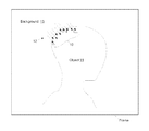
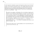
- FIG. 1A illustrates the penetration of poorly chosen motion vectors at the upper left edge of an object due to conventional Lagrangian-based optimization with a high value of ⁇ .
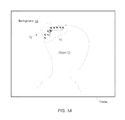
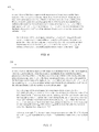
- FIG. 1B illustrates the concept of expected future benefit of a motion vector choice at a current block B.
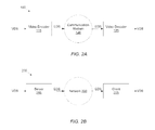
- FIG. 2A illustrates one embodiment of a video communication system 100 .
- FIG. 2B illustrates one embodiment of a client-server based system for supplying video data.
- FIG. 3 illustrates one embodiment of a method 300 for encoding video data.
- FIGS. 4 and 5 illustrate respective method embodiments for encoding video data using more than one reference frame.
- FIG. 6 illustrates one embodiment of a method 600 for computing a global median motion vector.
- FIG. 7 illustrates one embodiment of a method 700 for determining the most popular motion vectors in a given set of motion vectors.
- ASIC Application Specific Integrated Circuit
- AVC Advanced Video Coding
- DMVD Decoder-side Motion Vector Deviation
- HEVC High Efficiency Video Coding
- VDS Video Data Stream
- a memory medium is a medium configured for the storage and retrieval of information.
- Examples of memory media include: various kinds of semiconductor memory such as RAM and ROM; various kinds of magnetic media such as magnetic disk, tape, strip, film, etc.; various kinds of optical media such as CD-ROM and DVD-ROM; various media based on the storage of electrical charge and/or other physical quantities; media fabricated using various lithographic techniques; etc.
- the term “memory medium” may also include a set of two or more memory media which reside at different locations, e.g., at different computers that are connected over a network.
- Carrier Medium a memory medium as described above, as well as a physical transmission medium, such as a bus, network, and/or other physical transmission medium that conveys signals such as electrical, electromagnetic, or digital signals.
- Programmable Hardware Element includes various hardware devices comprising multiple programmable function blocks connected via a programmable interconnect. Examples include FPGAs (Field Programmable Gate Arrays), PLDs (Programmable Logic Devices), FPOAs (Field Programmable Object Arrays), and CPLDs (Complex PLDs).
- the programmable function blocks may range from fine grained (combinatorial logic or look up tables) to coarse grained (arithmetic logic units or processor cores).
- a programmable hardware element may also be referred to as “reconfigurable logic”.
- Computer System any of various types of computing or processing systems, including a personal computer (PC), mainframe computer system, workstation, laptop computer, tablet computer, network appliance, Internet appliance, personal digital assistant (PDA), mobile phone, media player, television system, video conferencing system, speakerphone, grid computing system, or other device or combinations of devices.
- PC personal computer
- mainframe computer system workstation
- laptop computer tablet computer
- network appliance Internet appliance
- PDA personal digital assistant
- mobile phone media player
- television system video conferencing system
- speakerphone grid computing system
- grid computing system any of various types of computing or processing systems, including a personal digital assistant (PDA), mobile phone, media player, television system, video conferencing system, speakerphone, grid computing system, or other device or combinations of devices.
- computer system can be broadly defined to encompass any device (or combination of devices) having at least one processor that executes instructions stored in a non-transitory memory medium.
- Automatically refers to an action or operation performed by a computer system (e.g., software executed by the computer system) or device (e.g., circuitry, programmable hardware elements, ASICs, etc.), without user input directly specifying or performing the action or operation.
- a computer system e.g., software executed by the computer system
- device e.g., circuitry, programmable hardware elements, ASICs, etc.
- An automatic procedure may be initiated by input provided by the user, but the subsequent actions that are performed “automatically” are not specified by the user, i.e., are not performed “manually”, where the user specifies each action to perform.
- a user filling out an electronic form by selecting each field and providing input specifying information is filling out the form manually, even though the computer system must update the form in response to the user actions.
- the form may be automatically filled out by the computer system where the computer system (e.g., software executing on the computer system) analyzes the fields of the form and fills in the form without any user input specifying the answers to the fields.
- the user may invoke the automatic filling of the form, but is not involved in the actual filling of the form (e.g., the user is not manually specifying answers to fields but rather they are being automatically completed).
- the present specification provides various examples of operations being automatically performed in response to actions the user has taken.
- Such a region includes previously coded motion vectors representing blocks that are close spatially and/or temporally.”
- Lagrangian optimization techniques are used to clarify what part of the video signal should be coded using what method.
- the AVC/H.264 video coding standard introduced the concept of the non-zero skip vector, which is based on the median of three neighboring motion vectors. This skip vector allows a block to be updated (i.e., motion compensated) even though no other information is transmitted describing changes to the block. Utilization of this technique makes it possible at low bit-rates to skip code large moving areas by simply allowing the prediction vector to govern the motion of blocks.
- the HEVC standard adopted a variation of techniques proposed by Kamp, Evertz & Wien (2008) on decoder-side motion vector derivation (DMVD) for inter-frame coding.
- DMVD decoder-side motion vector derivation
- the ad-hoc method works surprisingly well even for camera panning, considering its lack of global motion awareness. The reason the ad-hoc approach works is because motion tends to be highly correlated. (See Hsieh, Lu, Shyn & Lu, 1990). Since correlation occurs both spatially and temporally, by having an encoder choose the method of correlation, very little additional side information is needed to construct a global motion model.
- the method being adopted in HEVC comprises two encoding methods: (1) merge mode and (2) motion vector prediction for non-merge mode.
- Merge mode uses a motion vector “competition” scheme to choose the best neighboring motion vector to represent the motion of the present region. The chosen vector is described via an index.
- non-merge mode two spatial candidates are chosen, and the motion vector is differentially coded using a motion vector predictor. Both of these techniques can be considered part of ad hoc global motion since specific global motion vector data is not included in the transmitted information. Therefore, in some embodiments, we aim to improve global motion tracking when existing ad hoc encoding techniques are used.
- the key to the Lagrangian optimization is the selection of ⁇ , the Lagrange multiplier value, as disclosed by T. Wiegand (2001).
- ⁇ the Lagrange multiplier value
- the motion vector field is forced to adhere to stricter alignment at the expense of greater residual distortion.
- ⁇ the motion vector field is relaxed, to better represent the lowest distortion at the expense of sending more motion vector information.
- using a high value of ⁇ works fairly well, but in practice, the motion vector correlation is constrained by the position of the prediction vector components. In other words, in AVC, motion prediction is more accurate downward and to the right, since the prediction vectors are spatially above and to the left of the current vector.
- motion prediction propagates downward and to the right, but is mitigated somewhat by a temporal seed vector that is below and to the right, and therefore will provide a predictive component upward and to the left by one vector component.
- the motion-vector field can break down on the upper-left edges of low-texture objects. If there is too little texture to create significant distortion at high ⁇ values, then the motion-vector field will be ruled by the rate component and not be perturbed, causing object boundaries to be blurred.
- Lagrangian-based motion estimation at high values of ⁇ leads to globally poor choices of motion vector at blocks 10 interior to the object 11 (person's head) and at the upper-left edge of the object.
- Motion vectors 12 from the background 13 (which is assumed to be moving towards the bottom right) penetrate into the edge blocks 10 .
- the motion vectors selected for the edge blocks 10 are consistent with background motion vectors 12 , and thus, do not accurately represent the true motion of the object. (The object is assumed to be at a constant position within the image in the illustrated example.)
- the reason for the breakdown in the motion-vector field is that the motion vector search uses localized (or greedy) Lagrangian optimization, and thus, the optimal global motion solution is not realized.
- the selection of the motion vector v for a current block of the frame considers only (a) the distortion of the current block and (b) the immediate bit rate cost of encoding the motion vector v, and ignores the effect that selection might have on the selection of motion vectors in future blocks of the frame. It would be advantageous to incorporate some accounting for that future effect into the process of motion vector selection.
- the motion vector search for a current block may be performed with an improved cost function that accounts not only for the direct cost (i.e., local cost) of a motion vector selection but also for a future benefit of that selection on blocks not yet processed in the current frame.
- the expected future benefit of a motion vector selection v may be correlated with an average of distances ⁇ d(k) ⁇ corresponding to future blocks ⁇ B(k) ⁇ in the frame, where distance d(k) is the distance between the motion vector v and a pre-determined motion vector w(k) for a corresponding future block B(k) in the frame.
- FIG. 1B illustrates the concept of future benefit of a motion vector selection.
- a current block B according to a causal processing order of the blocks in the frame, there is an area 15 of blocks in the future region (i.e., non-causal region that has not yet been processed) of the frame that would benefit from an appropriate selection of motion vector at block B.
- the motion vector search for block X will be able to achieve a significantly lower cost for its best Lagrangian-optimized motion vector.
- the incorporation of the expected future benefit into the rate distortion function causes the motion vector search for the current block to be biased towards selecting a vector that is the same as (or similar to) future motion vectors in the frame.
- the following two-stage approach may be used: 1) generate an initial set of motion vectors that represent estimates (or predictions) of the motion vectors for the respective blocks of the current frame; and 2) for each block in the current frame, minimize a future-aware (global) cost function to select a final motion vector for that block, where the future-aware cost includes local costs and also an estimate of the benefit that a candidate motion vector v will provide on the selection of future motion vectors of the current frame.
- the future-aware cost may be based on (or utilize information derived from) the initial set of motion vectors.
- simulated annealing may be used to establish the final motion vectors for the current frame.
- one or more passes of motion vector searching may be performed to establish the initial set of motion vectors for the current frame, each pass using a successively larger value of ⁇ , and then a final pass with a largest value of ⁇ may be used to establish the final motion vectors.
- the expected future benefit may be computed using the motion vectors determined from the previous pass.
- One approach that may require the least amount of additional complexity involves using the motion vectors determined from the processing of the previous frame as predictors for the motion vectors in the current frame, i.e., as the initial set of motion vectors for the current frame.
- This approach is less complex than the hierarchical approach (that involves performing a preliminary low-resolution search), and in fact does not require any additional pass of motion searching to be performed per frame, although there is a temporal delay of one frame time, which can skew results during fast scene transitions.
- the expected future benefit may be computed without performing simulated annealing, e.g., as described above by using the motion vectors from the previous frame to define the initial set of motion vectors for the current frame. Setting the current motion vector to the most popular motion vector in the initial set has the greatest likelihood of allowing a future motion vector to use the current motion vector as a low-cost prediction. Therefore, the vector with the highest expected future benefit is the most popular motion vector from the initial set.
- the global cost may be minimized for each block of the current frame.
- the global cost may include a local rate-distortion (RD) cost and an expected noncausal benefit (expected future benefit).
- the expected noncausal benefit may involve evaluating a deviation associated with each of the most popular motion vectors in the initial set of motion vectors.
- the skip vector Since the skip vector has zero cost associated with it, and is judged based purely on its absolute distortion, to simplify the computation of the global cost, the most popular motion vectors may also be measured with no additional cost penalty, making them equivalent due to potential benefit from future cost savings.
- the motion vector selected on the basis of minimizing the global cost may have the highest probability of maximizing expected noncausal benefit while still maintaining close to minimum local direct cost.
- Incorporating the ability to correlate the selected motion vector to one of most popular motion vectors adds a segmentation decision for object boundaries.
- the algorithm can then model “fast freeze” simulated annealing of the motion vector field without the risk of binding to false motion vectors. This approach may allow higher ⁇ values to be used to more tightly correlate motion vectors, without losing the ability to abruptly change the vector flow on upper-left (noncausal prediction) object boundaries, thereby reducing global motion vector cost.
- FIG. 2A Video Communication System
- a video communication system 100 may be configured as shown in FIG. 2A .
- the video communication system 100 includes a video encoder 115 , a communication medium 120 and a video decoder 125 .
- the video encoder 115 may receive a video data stream VDS from a video data source, and encode the video data stream VDS to obtain an encoded data stream EDS.
- the video data stream may comprise a sequence of images, which are also referred to herein as video frames.
- the video encoder may employ any of the methods described herein to perform the encoding of the video data stream.
- the video encoder transmits the encoded data stream EDS onto the communication medium 120 , which transmits the encoded data stream to the video decoder 125 .
- the communication medium 120 may include a wired transmission medium such as an electrical cable, or an optical transmission medium such as optical fiber or the atmosphere, or a wireless transmission medium such as the atmosphere, or any combination of the foregoing.
- the communication medium 120 may be (or include) a computer network such as a wide area network or a local area network.
- the computer network may be the Internet or a network maintained by a provider of video programming or a cable television network.
- the video decoder 125 decodes the encoded data stream EDS to recover the video data stream VDS or an approximation to the video data stream.
- the video decoder may employ conventional means to perform the decoding.
- the recovered video data stream may be supplied to a display device for display to one or more users.
- the video encoder 115 may be realized by a computer executing stored program instructions, by dedicated digital circuitry such as one or more ASICs, by programmable hardware such as one or more FPGAs, or by any combination of the foregoing elements.
- video encoder 115 may be part of a video conferencing system or part of a videoconferencing endpoint.
- the video encoder 115 may be used in a mobile device such as a mobile phone, tablet computer, personal digital assistant, media player, etc.
- a mobile device may capture video (from its built-in camera) that has a significant amount of global motion.
- the video encoder 115 may encode the captured video stream with increased compression efficiency, without the computational burden of prior art methods.
- a mobile device may capture video and encode the video, e.g., using a conventional encoding algorithm, in order to obtain an initial encoded bitstream.
- the initial encoded bitstream may be uploaded to a server.
- the server may transcode the initial encoded bitstream to obtain a final encoded bitstream.
- the transcoding involves decoding the initial encoded bitstream to obtain an intermediate video stream, and re-encoding the intermediate video stream to obtain the final encoded bitstream.
- the video encoder 115 (or method corresponding thereto) may be used to perform the re-encoding.
- the video encoder 115 may realize improved compression efficiency (as compared to prior art methods).
- FIG. 2B Video Delivery System Using Client-Server Architecture
- FIG. 2B illustrates one set of embodiments of a video delivery system 200 that uses a client-server architecture.
- the video delivery system includes a server 215 and a client 225 that are connected via a network 220 .
- the client 225 may send a request for video data to the server 215 through the network 220 , e.g., by conventional means.
- the request may identify a particular video program or a particular piece of video content from a stored library of content or a particular television channel from a set of channels offered by a service provider.
- the server 215 may access a video data stream VDS from a video source, and encode the video data stream to obtain an encoded data stream EDS.
- the server may employ any of the methods described herein to perform the encoding of the video data stream.
- the server may transmit the encoded data stream EDS onto the network 220 , which transmits the encoded data stream to the client 225 .
- Network 220 may be variously realized as described above.
- the client 225 may decode the encoded data stream to recover the video data stream VDS or an approximation of the video data stream.
- the client may employ conventional means to perform the decoding.
- the recovered video data stream may be supplied to a display device for display to one or more users.
- FIG. 3 Method for Encoding Video Data
- a method 300 for encoding video data may include the operations shown in FIG. 3 .
- method 300 may include any subset of the features, elements and embodiments described below in connection with methods 400 , 500 , 600 and 700 .
- the video data may include a sequence of frames, with each frame comprising an image (e.g., a two-dimensional array of pixels).
- the method 300 may be performed by a processing agent, e.g., by a set of one or more processors executing stored program instructions, by dedicated digital circuitry such as one or more ASICs, by one or more programmable hardware elements, or by any combination of the foregoing.
- the processing agent may encode a current frame of the frame sequence with respect to a reference frame of the frame sequence.
- the reference frame may be a previous frame of the frame sequence or a following frame of the frame sequence.
- the action of encoding the current frame may include sequentially processing a plurality of blocks of the current frame according to an ordering of the blocks, e.g., according to a raster ordering.
- the plurality of blocks may be all of the blocks in the current frame, or a proper subset of the blocks in the current frame.
- the plurality of blocks preferably form a contiguous region.
- the action of processing a current block of the current frame may include performing a motion vector search for the current block over a plurality of test vector positions.
- the action of performing the motion vector search may include operations 315 and 320 as described below.
- the processing agent may compute a rate distortion value J(v) based on a linear combination of a distortion value D(v) and a bit cost value R(v,p,C).
- the distortion value D(v) represents a measure of distortion of the current block B v relative to a corresponding block in the reference frame.
- the corresponding block B v has a position in the reference frame that is defined by the test vector position v and a position of the current block in the current frame.
- the distortion value D(v) may be computed according to a conventional distortion function D, e.g., a distortion function specified by any of various video coding standards such as the AVC/H.264 standard or the H.265 standard.
- the bit cost value R(v,p,C) may depend on the test vector position v, a prediction vector p for the current block and a set C of one or more vectors c 1 , c 2 , . . . , c n .
- the prediction vector p may be obtained using conventional algorithms. For example, according to MPEG2, the prediction vector p may be determined using the motion vector of the spatially previous macroblock (the block to the left). As another example, according to AVC, the prediction vector p may be determined using the median of three motion vectors corresponding to the block to the left, the block above, and the block above right, with modifications depending on availability of the vectors. As yet another example, according to HVEC, an index is used to indicate which of the neighboring blocks is to supply the prediction vector for the current block, where the neighboring blocks may include the co-located block from a previous frame as well as spatially neighboring block in the current frame.
- the one or more vectors c 1 , c 2 , . . . , c n may be estimates of the n most statistically-popular motion vectors for the current frame, where n is a positive integer.
- the vectors c 1 , c 2 , . . . , c n may be determined by performing a histogram on motion vectors determined for the blocks in a previous (or nearby) frame of the frame sequence.
- the bit cost value R(v,p,C) may be computed as a sum of an x-component bit cost R X (v X ,p X ,C X ) and a y-component bit cost R Y (v Y ,p Y ,C Y ), where v X and v Y are x and y components of the test vector v, where p X and p Y are the x and y components of the prediction vector v, where C X is the set of x-components of the vectors c 1 , c 2 , . . . , c n , where C Y is the set of y-components of the vectors c 1 , c 2 , . . . , c n .
- R ( v,p) R 0 ( v,p )+ ⁇ R ( v,C ).
- the bias function ⁇ R may approach zero as the difference vector d approaches zero. In one embodiment, the bias function ⁇ R may be identically zero in a neighborhood of the prediction vector p.
- the plurality of test vector positions are restricted to a union of a neighborhood of the prediction vector p and neighborhoods of the vectors c 1 , c 2 , . . . , c n : v ⁇ N ( r p ,P ) ⁇ N ( r 1 ,c 1 ) ⁇ N ( r 2 ,c 2 ) ⁇ . . . ⁇ N ( r n ,c n ), where N(r,x) denotes a neighborhood of radius r centered at point x.
- This restriction may serve to accelerate the search for the minimizing test vector position v*.
- the first value may be determined by evaluating a standard rate function R 0 at the vector v, where the standard rate function R 0 has a minimum at the prediction vector p, e.g., as specified in any of various existing video encoding standards.
- the second value may be determined by evaluating a function R 1 at the vector v, where the function R 1 has a minimum at the vector c 1 .
- the minimum value of the function R 1 may be configured to be greater than the minimum value of the standard rate function R 0 .
- the action of encoding the current frame also includes computing the vectors c 1 , c 2 , . . . , c n by (1) computing a histogram of motion vectors associated with blocks in a nearby frame of the frame sequence, i.e., near to the current frame in the frame sequence; (2) identifying the n largest peaks in the histogram; and (3) for each of the n largest peaks, determining a location of the peak.
- Each of the n largest peak locations defines a corresponding one of the vectors c 1 , c 2 , . . . , c n .
- c n may be ordered according to size so that c 1 corresponds to the largest peak, c 2 to the next largest peak, and so on.
- the histogram may be a two-dimension histogram, i.e., a histogram whose bins form a two-dimensional array. The bins may be indexed by the x component of the motion vector and the y component of the motion vector.
- the histogram may be smoothed (e.g., low-pass filtered) with respect to the bin index variables before the identification of peaks.
- the location of a peak may be the location where the peak attains its maximum value. In another embodiment, the location of a peak may be the location of the center of mass of the peak. In yet another embodiment, the location of a peak may be the location (m X ,m Y ), where m X is the median value of the peak along the horizontal bin index and m Y is the median value of the peak along the vertical bin index. In other embodiments, the location of a peak may be some other statistic or parameter derived from the peak.
- the action of encoding the current frame also includes computing the vectors c 1 , c 2 , . . . , c n by computing a histogram of previously-computed motion vectors for the blocks of the current frame.
- the processing agent may perform two or more iterations of motion vector estimation on the current frame, with each iteration using a successively larger value of the Lagrange multiplier ⁇ . In a first iteration, the value of ⁇ may be small (while still positive), thus emphasizing the minimization of distortion in the selection of motion vectors for the respective blocks in the current frame.
- the value of ⁇ may be increased, thus placing increasing emphasis on the minimization of rate (number of encoded bits resulting from the motion vector selection) relative to minimization of distortion.
- the vectors c 1 , c 2 , . . . , c n used in the second iteration may be determined from a histogram of the motion vectors determined in the first iteration.
- the value of ⁇ may be further increased, thus placing even more emphasis on minimization of rate.
- the vectors c 1 , c 2 , . . . , c n used in the third iteration may be determined from a histogram on the motion vectors determined in the second iteration, and so on.
- n of vectors c 1 , c 2 , . . . , c n need not be the same in different iterations.
- the processing agent may generate initial motion vectors for the respective blocks in the current frame.
- a block may represent any appropriate subdivision of the frame, including but not limited to a macroblock as defined by the AVC/H.264 standard, or a prediction unit (PU) as defined by the H.265 standard.
- Those initial motion vectors may be generated prior to performing the encoding operation 310 of method 300 .
- the vectors c 1 , c 2 , . . . , c n used in method 300 may be the n most popular motion vectors among the initial motion vectors, e.g., derived from analyzing a histogram of the initial motion vectors.
- the initial motion vectors may be generated using any of various different techniques.
- the initial motion vectors may be based on the motion vectors determined for one or more previous frames of the video sequence, e.g., as a result of having previously executed method 300 on the previous frame(s).
- the initial motion vectors may be generated by performing a lower-resolution motion vector search on the current block, i.e., a motion vector search with lower resolution than the motion vector search performed in the encoding operation 310 of method 300 .
- a lower-resolution motion vector search with lower resolution than the motion vector search performed in the encoding operation 310 of method 300 .
- the blocks of the lower resolution search are larger than the blocks for the motion vector search performed in the encoding operation 310 .
- This approach may be referred to as the “hierarchical approach”.
- the lower-resolution search may be based on conventional Lagrangian-based optimization, i.e., without the inclusion of the expected future benefit.
- the initial motion vectors may be generated using a multipass annealing approach, where multiple passes of motion vector searching are performed, with each pass using a successively larger value of ⁇ .
- the motion vectors determined in each pass may be used as the basis for the next pass.
- Other methods for generating the initial motion vectors may also be used.
- FIGS. 4 and 5 Endcoding Using More than One Reference Frame
- a method 400 for encoding video data may include the operations shown in FIG. 4 .
- the video data may include a sequence of frames, with each frame comprising an image.
- the method 400 may also include any subset of the features, elements and embodiments described above in connection with method 300 and described below in connection with methods 500 , 600 and 700 .)
- the method 400 may be performed by a processing agent as described above.
- the processing agent may encode a frame of the frame sequence with respect to m reference frames of the frame sequence, where m is greater than one.
- the action of encoding the frame includes sequentially processing a plurality of blocks of the frame according to an ordering of the blocks.
- the motion vector search may include, for each m-tuple of the search space, computing a bit cost value R(v k ,p,E) for each vector v k in the m-tuple, where the bit cost value R(v k ,p,E) depends on vector v k , a prediction vector p for the block, and a vector set E.
- the vector set E includes one or more vectors from a set of vectors ⁇ e 1 , e 2 , . . . , e L ⁇ , where the vectors e 1 , e 2 , . . . , e L are estimates of the L most statistically-popular motion vectors of the frame, where L is a positive integer.
- the bit cost value R(v k ,p,E) may be determined, e.g., as variously described above in connection with method 300 . However, more than one statistically-popular motion vector may also be used.
- a method 500 for encoding video data may include the operations shown in FIG. 5 .
- the video data may include a sequence of frames, with each frame comprising an image.
- the method 500 may also include any subset of the features, elements and embodiments described above in connection with methods 300 and 400 , and described below in connection with methods 600 and 700 .)
- the method 500 may be performed by a processing agent as described above.
- the processing agent may encode a frame of the frame sequence with respect to m reference frames of the frame sequence, where m is greater than one.
- the action of encoding the frame may include sequentially processing a plurality of blocks of the frame according to an ordering of the blocks.
- the action of processing a given block of the frame includes performing a motion vector search for the block over a search space of m-tuples (v 1 , v 2 , . . . , v m ).
- the motion vector search may include operations 515 and 520 as described below.
- the prediction vector p for the block may be determined as variously described above.
- the processing agent may determine an m-tuple T* of the search space that gives a minimum value M* of M.
- the vector v kmin corresponding to the m-tuple T* is selected as a motion vector for the block.
- the action of processing the block includes: encoding a difference between the selected motion vector for the block and the prediction vector p for the block to obtain output bits; and transmitting the output bits to a video decoder via a communication medium.
- a method for encoding a current frame within a frame sequence comprising:
- processing a current block includes:
- searching includes: (a) computing one or more rate distortion values for each of the test vector positions, wherein a first of the one or more rate distortion values for each of the test vector positions is computed according to a first rate-distortion function, wherein the first rate-distortion function includes a first bias that increases the likelihood of providing a lower rate-distortion value for one or more future blocks, wherein said one or more future blocks are blocks that have not yet been processed in said sequential processing of the blocks; and (b) selecting one of the test vector positions that has a minimum rate-distortion value to be a motion vector for the current block.
- the first bias is a first monotonic function of distance of test vector position with respect to a first of the test vector positions, wherein the first monotonic function has a minimum at the first test vector position.
- a second of the one or more rate-distortion values for each test vector position is computed according to a second rate-distortion function, wherein the second rate-distortion function includes a second bias that is a second monotonic function of distance of test vector position with respect to a second of the test vector positions, wherein the second monotonic function has a minimum at the second test vector position.
- processing the current block also includes: encoding the selected motion vector for the current block to obtain encoded bits; and transmitting the encoded bits to a video decoder via a communication medium
- each of said processors is configured to perform said sequentially processing on a corresponding plurality of blocks in the current frame.
- a method for encoding video data including a frame sequence comprising:
- processing a current block of the current frame includes performing a motion vector search for the current block over a plurality of test vector positions, wherein said performing the motion vector search includes: (a) for each test vector v in the plurality of test vector positions, computing one or more rate distortion values, wherein a first of the one or more rate distortion values for each test vector position v is computed according to a first rate-distortion function, wherein the first rate-distortion function includes a bias that increases the likelihood of providing a lower rate-distortion value for one or more future blocks, wherein said one or more future blocks are blocks that have not yet been processed in said sequential processing of the blocks; and (b) selecting one of the test vector positions that has a minimum rate-distortion value.
- the most popular motion vectors c 1 , c 2 , . . . , c n (or the most popular motion vectors e 1 , e 2 , . . . , e L ) used in the above-described methods may be derived from an initial set of motion vectors for the current frame.
- the blocks of the current frame may be processed in a raster fashion.
- a motion vector search for a current block uses the motion vectors that have already been determined for blocks to the left and above the current block. Motion vectors below and to the right have not yet been computed, and therefore the motion search at the current block cannot use that future information.
- any of the various methods described herein may generate initial motion vectors that estimate the motion vectors of the respective blocks of the current frame.
- a wide variety of techniques may be used to generate the initial motion vectors.
- the initial motion vectors may be generated based on the motion vectors of a previous frame (or frames).
- Motion video has high temporal redundancy, i.e., the previous frame tends to share many similar characteristics with the current frame. This temporal redundancy can be exploited to allow some non-causal estimates of the motion below and to the right of the current vector in the current frame.
- the former may be used as an estimate for the latter.
- the initial motion vectors may be generated from a hierarchical (lower resolution) search.
- Motion video also has high spatial redundancy, i.e., motion vectors in the local spatial neighborhood tend to be similar to the current block's motion vector.
- This spatial redundancy can be exploited by performing reduced-resolution motion estimation on the whole image, which takes considerably less compute power than a full resolution search. For example, if the pixel dimensions of the generic block are reduced by 1 ⁇ 2 in the horizontal and vertical directions, the complexity of the sum of absolute differences (SAD) calculation is reduced by 1 ⁇ 4. Further, the motion vector search range is also reduced by 1 ⁇ 2 in both the horizontal and vertical directions, so the number of SAD tests is also reduced by 1 ⁇ 4. This leads to a total reduction in complexity to 1/16 of the original complexity by simply reducing the dimensions by half. Reducing the dimensions of the image by half again reduces the complexity to 1/256 of a full-resolution motion estimation.
- SAD sum of absolute differences
- the initial motion vectors may be generated from a multi-pass approach.
- a plurality of passes of motion estimation are performed on the current frame. Each pass may include executing the process of estimating motion for every block in the current frame. Each pass of motion estimation may use a conventional rate distortion function.
- the motion vectors generated in the last of the plurality of passes are used as the initial motion vectors.
- each pass except for the first pass may use the presently-disclosed rate distortion function that accounts for expected future benefit (as variously described above).
- the motion vectors determined from each pass may be used as the basis for the next pass (e.g., used to generate the popular motion vectors c 1 , c 2 , . . . , c n for the next pass as variously described above).
- Each pass may use a larger value of ⁇ .
- This multi-pass approach may produce initial motion vectors of higher quality, but it requires increased computational complexity than the previous frame approach or the hierarchical approach.
- any of various techniques may be used to determine the most popular motion vectors from the initial set of motion vectors, e.g., techniques including but not limited to the following: Global Mean Motion Vector (GMV); Global Median Motion Vector (GMED); Most Likely Motion Vector (MLMV); and Adjusted MLMV.
- GMV Global Mean Motion Vector
- GMED Global Median Motion Vector
- MLMV Most Likely Motion Vector
- Adjusted MLMV Adjusted MLMV.
- the GMV technique may work well when there is uniform camera movement such as pan or tilt.
- the GMED technique improves on GMV by always producing a real motion vector (i.e., one of the motion vectors of the initial set).
- the MLMV technique improves upon GMED by allowing K ⁇ 2 image objects to be accurately handled.
- the K most popular motion vectors identified by the MLMV technique correspond to the velocities of the K objects.
- Adjusted MLMV technique also handles K ⁇ 2 objects, but throws out uninteresting motion vector candidates such as the (0,0) motion vector since it is easy to test that point without a special global motion analysis.
- FIG. 6 The Algorithm for GMED
- FIG. 6 illustrates one embodiment of a method 600 for determining a popular motion vector (or a representative motion vector) from the initial set of motion vectors for the current frame.
- the method 600 may use the GMED technique.
- the method computes the mean ( ⁇ ) and standard deviation ( ⁇ ) for both the X and Y components of the initial motion vectors.
- the method computes ⁇ X , ⁇ Y , ⁇ X and ⁇ Y .
- Each standard deviation may be calculated or estimated according to any known method.
- each standard deviation may be calculated via a 2-pass algorithm, as proposed by Tibshirani (2008).
- each standard deviation is computed using a single pass algorithm.
- the x-component standard deviation ⁇ X may be computed by first computing the x-component variance according to the following expression:
- the standard deviation ⁇ X may then be determined by taking the square-root of the x-component variance. The square-root can be performed using a fast approximation technique such as Q_rsqrt( ) (Software, 2006). The y component standard deviation ⁇ Y may be similarly computed.
- the method forms a two-dimensional array of bins, e.g., a B X ⁇ B Y array of bins.
- the two-dimensional array of bins represents (i.e., covers) the following rectangular region in the motion vector space: [ ⁇ X ⁇ K X ⁇ X , ⁇ X +K X ⁇ X ] ⁇ [ ⁇ Y ⁇ K Y ⁇ Y , ⁇ Y +K Y ⁇ Y ], where the notation [a,b] denotes the closed interval from a to b, where K X and K Y are positive scale factors. Scale factors K X and K Y are typically greater than or equal to one.
- the rectangular region may be partitioned into B X B Y smaller rectangles, with each bin of the B X ⁇ B Y array being assigned a corresponding one of the smaller rectangles.
- the number of bins B X B Y will affect the accuracy of the determination of the median vector. Fewer bins make the median calculation faster, but less accurate. More bins improve accuracy at the expense of an increase in complexity.
- the bins in the horizontal direction are indexed by index variable b X .
- index variable b X index variable
- each value of b X identifies a corresponding subinterval along the horizontal axis.
- the bins in the vertical direction are indexed by the index variable b Y .
- each value of b Y identifies a corresponding subinterval along the vertical axis.
- the method maps the initial motion vectors to bins to produce a two-dimensional histogram.
- initial motion vectors falling outside the range of all the bins i.e., outside the above-identified rectangular region are not mapped to any bin.
- the method identifies the bin index vector (m X , m Y ) such that m X identifies the horizontal subinterval containing the median of the histogram with respect to the x coordinate, and m Y identifies the vertical subinterval containing the median of the histogram with respect to the y coordinate.
- m X identifies the subinterval containing the median of the x marginal distribution f X (x) of the histogram f X,Y (x,y)
- m Y identifies the subinterval containing the median of the y marginal distribution f Y (y) of the histogram f X,Y (x,y).
- the media motion vector is defined by the bin index vector
- the media motion vector may be set equal to the geometric center of the small rectangle covered by the bin (m X ,m Y ).
- FIG. 7 The Algorithm for MLMV
- FIG. 7 illustrates one embodiment of a method 700 for determining statistically-popular motion vectors (or representative motion vectors) from the initial motion vectors for the current frame.
- the method 700 uses the most likely motion vector (MLMV) technique.
- MLMV most likely motion vector
- the method computes the mean ( ⁇ ) and standard deviation ( ⁇ ) for both the X and Y components of the initial motion vectors, e.g., as discussed above in relation to FIG. 6 .
- the method forms a two-dimensional array of bins, e.g., a B X ⁇ B Y array of bins, in a manner similar to that discussed above in relation to FIG. 6 .
- the two-dimensional array of bins covers the following rectangular region in the motion vector space: [ ⁇ X ⁇ K X ⁇ X , ⁇ X +K X ⁇ X ] ⁇ [ ⁇ Y ⁇ K Y ⁇ Y , ⁇ Y +K Y ⁇ Y ], where K X and K Y are positive scale factors. Scale factors K X and K Y are typically greater than or equal to one.
- the method maps the initial motion vectors to the bins to produce a two-dimensional histogram.
- Each initial motion vector is mapped to the bin that spatially contains the initial motion vector.
- Initial motion vectors that fall outside the above-identified rectangular region may be discarded.
- the Adjusted MLMV technique is a slight modification of the MLMV technique.
- the Adjusted MLMV technique involves testing each initial motion vector to determine whether the initial motion vector is equal to any of the one or more vectors in an uninteresting vector set.
- the uninteresting vector set may include the zero vector (0,0). If an initial motion vector is equal to one of the vectors in the uninteresting vector set, it may be discarded, i.e., not allowed to contribute to the histogram.
- the method may perform a two-dimensional smoothing operation (e.g., a low-pass filtering) on the histogram to obtain a smoothed histogram.
- the filtering operation serves to smooth out small scale discontinuities in the bin population values of the histogram.
- the two-dimensional kernel (impulse response) used to perform the filtering has the following form:
- the kernel may conform to a Gaussian function or a 2D sinc function or a pyramidal function, etc.
- the method may determine the positions of the n largest peaks in the smoothed histogram. Those positions define the vectors c 1 , c 2 , . . . , c n described above in connection with method 300 . Any of a wide variety of peak identification algorithms may be used to identify the n largest peaks. Interpolation may be used to estimate the x and y coordinates of the location of each peak with a resolution greater than the resolution of the respective coordinates b X and b Y of the bin index vector (b X ,b Y ).
- the method may impose a minimum separation constraint on the n largest peaks. If two local maxima in the smoothed histogram are closer together in motion vector space than a predetermined minimum value, the two maxima may be counted as being part of one unified peak. This constraint prevents the peak identification algorithm from falsely identifying closely-spaced noise-generated local maxima as distinct peaks.
- the minimum separation constraint may be expressed in terms of a minimum X separation and a minimum Y separation. (The minimum X separation may be specified in terms of a predetermined percentage of the standard deviation ⁇ X .
- the minimum Y separation may be specified in terms of a predetermined percentage of the standard deviation ⁇ Y .
- the above-described video encoding methods may be used to perform simulated annealing on a frame, i.e., to adjust the motion vector field of a frame toward the true motion vector field of one or more objects in the frame.
- the motion-estimation algorithm may be able to make a motion vector choice that achieves an appropriate balance between minimization of local cost (local distortion and local bit rate) and maximization of expected future benefit.
- the motion estimation algorithm can immediately recognize the cost savings of switching the motion vector to the appropriate one of the most-popular motion vectors c 1 , c 2 , . . . , c n without incurring a significant cost penalty for doing so.
- the final motion vector field may provide better rate-distortion characteristics than a motion vector field that was generated based on the minimization of a conventional rate-distortion function.
- Embodiments of the present invention may be realized in any of various forms.
- the present invention may be realized as a computer-implemented method, a computer-readable memory medium, or a computer system.
- the present invention may be realized using one or more custom-designed hardware devices such as ASICs.
- the present invention may be realized using one or more programmable hardware elements such as FPGAs.
- a non-transitory computer-readable memory medium may be configured so that it stores program instructions and/or data, where the program instructions, if executed by a computer system, cause the computer system to perform a method, e.g., any of a method embodiments described herein, or, any combination of the method embodiments described herein, or, any subset of any of the method embodiments described herein, or, any combination of such subsets.
- a computer system may be configured to include a processor (or a set of processors) and a memory medium, where the memory medium stores program instructions, where the processor is configured to read and execute the program instructions from the memory medium, where the program instructions are executable to implement any of the various method embodiments described herein (or, any combination of the method embodiments described herein, or, any subset of any of the method embodiments described herein, or, any combination of such subsets).
- the computer system may be realized in any of various forms.
Abstract
Description
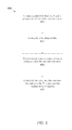
J(v)=D(v)+λR(v,p),
where λ is a positive scalar value. D(v) is a distortion function that measures the distortion of the current block relative to a corresponding block Bv of the reference frame. The corresponding block Bv has a position in the reference frame that is defined by the test vector v and the position of the current block in the current frame. R(v,p) is a rate cost function that measures the number of bits that will be required to transmit the vector difference v−p, where p is a prediction vector for the current block. The number of required bits is typically an increasing function of the distance ∥v−p∥. (The prediction vector p may be obtained by any of various known means. For example, the prediction vector may be a motion vector that has already been selected for one of the blocks temporally or spatially neighboring the current block, or a combination of motion vectors that have already been selected for two or more neighboring blocks.) When λ is small, the search emphasizes more the minimization of distortion than the minimization of bit rate. A frame whose motion vectors are chosen on the basis of J minimization with small λ may exhibit high visual quality upon decode and display. Conversely, when λ is large, the search emphasizes more the minimization of bit rate than the minimization of distortion. Thus, the motion vectors generated for the respective blocks of the current frame will exhibit spatial inertia, i.e., the tendency to avoid radical changes between neighboring blocks of the frame. (The strong emphasis on bit rate minimization means that it is very costly to allow the difference v−p to be large.) Large changes in the motion vector may be limited to situations where the distortion measure D(v) would be large if the difference v−p were small in magnitude. A frame whose motion vectors are chosen on the basis of J minimization with larger λ may exhibit higher compression ratio but lower visual quality.
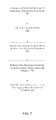
{∥v−c j ∥:j=1,2, . . . ,n}.
R(v,p,C)=R 0(∥v−p∥)−ΔR(∥v−c 1 ∥,∥v−c 2 ∥, . . . ,∥v−c n∥),
where R0 is a conventional bit rate cost function, e.g., a bit rate cost function as defined by any of a variety of existing video coding standards, where ΔR is a function that represents the expected future benefit for choosing the vector v as the motion vector for the current block. In one embodiment, the expected future benefit function ΔR may also include a dependency on the distance ∥v−p∥, i.e.,
R(v,p,C)=R 0(∥v−p∥)−ΔR(∥v−c 1 ∥,∥v−c 2 ∥, . . . ,∥v−c n ∥,∥v−p∥).
v*=arg min J(v).
Global_MV—Cost=Direct_Cost−Expected_Future_Benefit.
Global_Cost=Distortion+λ(Bit_Cost−Expected_Noncausal_Benefit).
v*=arg min J(v).
In some embodiments, the rate distortion value J(v) is given by the expression J(v)=D(v)+λR(v,p,C), where λ is a positive scalar value.
E X =R 0(v X −p X),
F X=min{E X,MinXCost},
G X=log2(1+|v X −c 1X|),
H X=min {1,G X /N X},
R X(v X ,p X ,C X)=E X−(E X −F X)(1−H X)*XScaleFactor,
where R0(z) is a conventional bit-rate cost function, e.g., a bit-rate cost function defined by any of various existing video coding standards, where MinXCost, NX and XScaleFactor are parameters, where c1X is the x component of the vector c1, where int{z} denotes the integer part of z, where |z| denotes the absolute value of z.
E Y =R 0(v Y −p Y),
F Y=min{E Y,MinYCost},
G Y=log2(1+|v Y −c 1Y|),
H Y=min {1,G Y /N Y},
R Y(v Y ,p Y ,C Y)=E Y−(E Y −F Y)(1−H Y)*YScaleFactor,
where MinYCost, NY and YScaleFactor are parameters, where c1Y is the y component of the vector c1.
R(v,p,C)=R 0(v,p)+ΔR(v,C).
The bias function ΔR may approach zero as the difference vector d approaches zero. In one embodiment, the bias function ΔR may be identically zero in a neighborhood of the prediction vector p.
vεN(r p ,P)∪N(r 1 ,c 1)∪N(r 2 ,c 2)∪ . . . ∪N(r n ,c n),
where N(r,x) denotes a neighborhood of radius r centered at point x. This restriction may serve to accelerate the search for the minimizing test vector position v*.
where N is the number of the initial motion vectors, where xi is the x component of the ith one of the initial motion vectors. The standard deviation σX may then be determined by taking the square-root of the x-component variance. The square-root can be performed using a fast approximation technique such as Q_rsqrt( ) (Software, 2006). The y component standard deviation σY may be similarly computed.
[μX −K XσX,μX +K XσX]×[μY −K YσY,μY +K YσY],
where the notation [a,b] denotes the closed interval from a to b, where KX and KY are positive scale factors. Scale factors KX and KY are typically greater than or equal to one. (However, in some embodiments, one or both of the scale factors may be less than one.) The rectangular region may be partitioned into BXBY smaller rectangles, with each bin of the BX×BY array being assigned a corresponding one of the smaller rectangles. The number of bins BXBY will affect the accuracy of the determination of the median vector. Fewer bins make the median calculation faster, but less accurate. More bins improve accuracy at the expense of an increase in complexity. The bins in the horizontal direction are indexed by index variable bX. Thus, each value of bX identifies a corresponding subinterval along the horizontal axis. The bins in the vertical direction are indexed by the index variable bY. Thus, each value of bY identifies a corresponding subinterval along the vertical axis.
[μX −K XσX,μX +K XσX]×[μY −K YσY,μY +K YσY],
where KX and KY are positive scale factors. Scale factors KX and KY are typically greater than or equal to one. (For example, in one embodiment, KX=KY=1.50.) There is a tradeoff on the optimal number of bins to use. A larger number of bins will require a larger amount of computation time to arrive at the final MLMV results. A smaller number of bins implies that the resolution of the final MLMV results will be low because each bin corresponds to a larger area in the motion vector space.
However, a wide variety of other forms are possible and contemplated. For example, in other embodiments, the kernel may conform to a Gaussian function or a 2D sinc function or a pyramidal function, etc.
Claims (17)
Priority Applications (1)
| Application Number | Priority Date | Filing Date | Title |
|---|---|---|---|
| US13/957,269 US9438928B2 (en) | 2012-11-05 | 2013-08-01 | Mechanism for video encoding based on estimates of statistically-popular motion vectors in frame |
Applications Claiming Priority (3)
| Application Number | Priority Date | Filing Date | Title |
|---|---|---|---|
| US201261722524P | 2012-11-05 | 2012-11-05 | |
| US201261725343P | 2012-11-12 | 2012-11-12 | |
| US13/957,269 US9438928B2 (en) | 2012-11-05 | 2013-08-01 | Mechanism for video encoding based on estimates of statistically-popular motion vectors in frame |
Publications (2)
| Publication Number | Publication Date |
|---|---|
| US20140126638A1 US20140126638A1 (en) | 2014-05-08 |
| US9438928B2 true US9438928B2 (en) | 2016-09-06 |
Family
ID=50622369
Family Applications (1)
| Application Number | Title | Priority Date | Filing Date |
|---|---|---|---|
| US13/957,269 Active 2034-11-16 US9438928B2 (en) | 2012-11-05 | 2013-08-01 | Mechanism for video encoding based on estimates of statistically-popular motion vectors in frame |
Country Status (1)
| Country | Link |
|---|---|
| US (1) | US9438928B2 (en) |
Families Citing this family (13)
| Publication number | Priority date | Publication date | Assignee | Title |
|---|---|---|---|---|
| JP6102680B2 (en) * | 2013-10-29 | 2017-03-29 | ソニー株式会社 | Encoding device, decoding device, encoded data, encoding method, decoding method, and program |
| EP3264762A4 (en) | 2015-03-10 | 2018-05-02 | Huawei Technologies Co., Ltd. | Image prediction method and related device |
| US10430664B2 (en) * | 2015-03-16 | 2019-10-01 | Rohan Sanil | System for automatically editing video |
| US11330284B2 (en) * | 2015-03-27 | 2022-05-10 | Qualcomm Incorporated | Deriving motion information for sub-blocks in video coding |
| US10602174B2 (en) | 2016-08-04 | 2020-03-24 | Intel Corporation | Lossless pixel compression for random video memory access |
| US10715818B2 (en) * | 2016-08-04 | 2020-07-14 | Intel Corporation | Techniques for hardware video encoding |
| CA2986600A1 (en) * | 2016-11-24 | 2018-05-24 | Ecole De Technologie Superieure | Method and system for parallel rate-constrained motion estimation in video coding |
| US10291925B2 (en) | 2017-07-28 | 2019-05-14 | Intel Corporation | Techniques for hardware video encoding |
| US10812823B2 (en) | 2018-07-11 | 2020-10-20 | Apple Inc. | Global motion vector video encoding systems and methods |
| US11025913B2 (en) | 2019-03-01 | 2021-06-01 | Intel Corporation | Encoding video using palette prediction and intra-block copy |
| WO2020248105A1 (en) * | 2019-06-10 | 2020-12-17 | Oppo广东移动通信有限公司 | Predicted value determination method, coder and computer storage medium |
| US10855983B2 (en) | 2019-06-13 | 2020-12-01 | Intel Corporation | Encoding video using two-stage intra search |
| US11330296B2 (en) | 2020-09-14 | 2022-05-10 | Apple Inc. | Systems and methods for encoding image data |
Citations (2)
| Publication number | Priority date | Publication date | Assignee | Title |
|---|---|---|---|---|
| US20060002472A1 (en) * | 2004-06-30 | 2006-01-05 | Mehta Kalpesh D | Various methods and apparatuses for motion estimation |
| US20070237232A1 (en) * | 2006-04-07 | 2007-10-11 | Microsoft Corporation | Dynamic selection of motion estimation search ranges and extended motion vector ranges |
-
2013
- 2013-08-01 US US13/957,269 patent/US9438928B2/en active Active
Patent Citations (2)
| Publication number | Priority date | Publication date | Assignee | Title |
|---|---|---|---|---|
| US20060002472A1 (en) * | 2004-06-30 | 2006-01-05 | Mehta Kalpesh D | Various methods and apparatuses for motion estimation |
| US20070237232A1 (en) * | 2006-04-07 | 2007-10-11 | Microsoft Corporation | Dynamic selection of motion estimation search ranges and extended motion vector ranges |
Non-Patent Citations (15)
| Title |
|---|
| Chang, M. M., Takalp, A. M., & Sezan, M. I.; "Simultaneous Motion Estimation and Segmentation"; IEEE Transactions on Image Processing, vol. 6, No. 9; Sep. 1997, pp. 1326-1333. |
| Chung, W. C., & Kossentini, F. & Smith, M.J.T.; "An Efficient Motion Estimation Technique Based on a Rate-Distortion Criterion"; Proceedings of the Acoustics, Speech, and Signal Processing, vol. 4; May 7-10, 1996; pp. 1926-1929. |
| Girod, B.; "Rate-Constrained Motion Estimation"; Visual Communications and Image Processing, SPIE 2308; Sep. 16, 1994; pp. 1026-1034. |
| Glantz, A., Krutz, A., & Sikora, T: "Adaptive Global Motion Temporal Prediction for Video Coding"; Picture Coding Symposium (PCS) 2010; Dec. 8-10, 2010; pp. 202-205. |
| Hsieh, C., Lu, P., Shyn, J., & Lu, E.; "Motion Estimation Algorithm Using Interblock Correlation"; Electronics Letters, vol. 26, Issue 5; Mar. 1, 1990; pp. 276-277. |
| Kamp, S., Evertz, M., & Wien, M.; "Decoder Side Motion Vector Derivation for Inter Frame Coding"; IEEE International Conference on Image Processing; Oct. 12-15, 2008; pp. 1120-1123. |
| Kossentini, F., Lee, Y., Smith, M.J.T., & Ward, R.K.; "Predictive RD Optimized Motion Estimation for Very Low Bit-Rate Video Coding"; IEEE Journal on Selected Areas in Communications, vol. 15, Issue 9; Dec. 1997; pp. 1752-1763. |
| Software, R. F.; "Origin of Quake3's Fast InvSqrt()"; Published Nov. 29, 2006; Last Updated Mar. 21, 2007; Retrieved Oct. 14, 2014 from Beyond 3D:http://www.beyond3d.com/content/articles/8/; 6 pages. |
| Stiller, C., & Konrad, J.; "Estimating Motion in Image Sequences"; IEEE Signal Processing Magazine, vol. 16, Issue 4; Jul. 1999; pp. 70-91. |
| Sullivan, G. J., & Wiegand, T.; "Rate-Distortion Optimization for Video Compression"; IEEE Signal Processing Magazine, vol. 15, Issue 6; Nov. 1998; pp. 74-90. |
| Sullivan, G. J., Ohm, J.-R., Han, W.-J., & Wiegand, T.; Overview of the High Efficiency Video Coding (HEVC) Standard; IEEE Transactions on Circuits and Systems for Video Technology, vol. 22, Issue 12; Dec. 2012; pp. 1649-1668. |
| Tibshirani, R. J.; "Fast Computation of the Median by Successive Binning"; The Computing Research Repository (CoRR); abs/0806.3301; Jun. 20, 2008; 14 pages. |
| Wiegand, T. & Girod, B.; "Lagrange Multiplier Selection in Hybrid Video Coder Control"; 2001 International Conference on Image Processing, vol. 3; Oct. 7-10, 2001; pp. 542-545. |
| Wiegand, T., Schwarz, H., Joch, A., Kossentini, F., & Sullivan, G. J.; "Rate-Constrained Coder Control and Comparison of Video Coding Standards"; IEEE Transactions on Circuits and Systems for Video Technology; vol. 13, No. 7; Jul. 2003; pp. 688-703. |
| Wiegand, T., Steinbach, E., & Girod, B.; "Aline Multipicture Motion-Compensated Prediction"; IEEE Transactions on Circuits and Systems for Video Technology; Feb. 2005; pp. 197-209. |
Also Published As
| Publication number | Publication date |
|---|---|
| US20140126638A1 (en) | 2014-05-08 |
Similar Documents
| Publication | Publication Date | Title |
|---|---|---|
| US9438928B2 (en) | Mechanism for video encoding based on estimates of statistically-popular motion vectors in frame | |
| US11546627B2 (en) | Moving picture decoding method and moving picture encoding method | |
| CN110581997B (en) | Motion vector precision refinement | |
| CN110809887B (en) | Method and apparatus for motion vector modification for multi-reference prediction | |
| Wiegand et al. | Long-term memory motion-compensated prediction | |
| US9621917B2 (en) | Continuous block tracking for temporal prediction in video encoding | |
| US8290289B2 (en) | Image encoding and decoding for multi-viewpoint images | |
| US11070834B2 (en) | Low-complexity method for generating synthetic reference frames in video coding | |
| US8625678B2 (en) | Method for scalable video coding on a plurality of space resolution levels | |
| US7321626B2 (en) | System and method for predictive motion estimation using a global motion predictor | |
| US20080159398A1 (en) | Decoding Method and Coding Method | |
| US20110164677A1 (en) | Complexity Allocation for Video and Image Coding Applications | |
| EP2129133A2 (en) | Video coding device and video decoding device with a motion compensated interframe prediction | |
| US20040156437A1 (en) | Method for encoding and decoding video information, a motion compensated video encoder and a corresponding decoder | |
| KR20210109049A (en) | Optical flow estimation for motion compensated prediction in video coding | |
| US11516475B2 (en) | Image encoding/decoding method and device for performing PROF, and method for transmitting bitstream | |
| US11889109B2 (en) | Optical flow based video inter prediction | |
| US11949874B2 (en) | Image encoding/decoding method and device for performing prof, and method for transmitting bitstream | |
| EP2605518B1 (en) | Encoding device, decoding device, encoding method, and decoding method | |
| Shen et al. | Context-adaptive based CU processing for 3D-HEVC | |
| US20220337842A1 (en) | Image encoding/decoding method and device for performing bdof, and method for transmitting bitstream | |
| US20230050102A1 (en) | Triangulation-Based Adaptive Subsampling of Dense Motion Vector Fields | |
| US20240064336A1 (en) | Image decoding apparatus and image encoding apparatus using ai, and methods performed thereby | |
| Vranješ et al. | Influence of block size on motion vector estimation error in enhancement of video temporal resolution | |
| Kim et al. | Multilevel Residual Motion Compensation for High Efficiency Video Coding |
Legal Events
| Date | Code | Title | Description |
|---|---|---|---|
| AS | Assignment |
Owner name: LOGITECH EUROPE S.A., SWITZERLAND Free format text: ASSIGNMENT OF ASSIGNORS INTEREST;ASSIGNOR:SIEVERS, JOHN C.;REEL/FRAME:030929/0014 Effective date: 20130801 |
|
| AS | Assignment |
Owner name: LIFESIZE, INC., TEXAS Free format text: ASSIGNMENT OF ASSIGNORS INTEREST;ASSIGNOR:LOGITECH EUROPE S.A.;REEL/FRAME:037833/0611 Effective date: 20160222 |
|
| STCF | Information on status: patent grant |
Free format text: PATENTED CASE |
|
| CC | Certificate of correction | ||
| AS | Assignment |
Owner name: SILICON VALLEY BANK, AS ADMINISTRATIVE AGENT AND COLLATERAL AGENT, CALIFORNIA Free format text: SECURITY INTEREST;ASSIGNORS:SERENOVA, LLC;LIFESIZE, INC.;LO PLATFORM MIDCO, INC.;REEL/FRAME:052066/0126 Effective date: 20200302 |
|
| MAFP | Maintenance fee payment |
Free format text: PAYMENT OF MAINTENANCE FEE, 4TH YEAR, LARGE ENTITY (ORIGINAL EVENT CODE: M1551); ENTITY STATUS OF PATENT OWNER: LARGE ENTITY Year of fee payment: 4 |
|
| AS | Assignment |
Owner name: WESTRIVER INNOVATION LENDING FUND VIII, L.P., WASHINGTON Free format text: SECURITY INTEREST;ASSIGNOR:LIFESIZE, INC.;REEL/FRAME:052179/0063 Effective date: 20200302 |
|
| MAFP | Maintenance fee payment |
Free format text: PAYMENT OF MAINTENANCE FEE, 8TH YEAR, LARGE ENTITY (ORIGINAL EVENT CODE: M1552); ENTITY STATUS OF PATENT OWNER: LARGE ENTITY Year of fee payment: 8 |