US9441853B2 - Teflon pocket slide gate and method of assembly - Google Patents
Teflon pocket slide gate and method of assembly Download PDFInfo
- Publication number
- US9441853B2 US9441853B2 US14/081,851 US201314081851A US9441853B2 US 9441853 B2 US9441853 B2 US 9441853B2 US 201314081851 A US201314081851 A US 201314081851A US 9441853 B2 US9441853 B2 US 9441853B2
- Authority
- US
- United States
- Prior art keywords
- frame side
- channel
- frame
- assembly
- guide
- Prior art date
- Legal status (The legal status is an assumption and is not a legal conclusion. Google has not performed a legal analysis and makes no representation as to the accuracy of the status listed.)
- Active, expires
Links
- 239000004809 Teflon Substances 0.000 title claims abstract description 56
- 229920006362 Teflon® Polymers 0.000 title claims abstract description 56
- 238000000034 method Methods 0.000 title description 4
- 238000010586 diagram Methods 0.000 description 16
- 238000003466 welding Methods 0.000 description 11
- 238000009423 ventilation Methods 0.000 description 3
- 230000000712 assembly Effects 0.000 description 2
- 238000000429 assembly Methods 0.000 description 2
- 238000005219 brazing Methods 0.000 description 2
- 239000000463 material Substances 0.000 description 2
- 238000012986 modification Methods 0.000 description 2
- 230000004048 modification Effects 0.000 description 2
- 238000004080 punching Methods 0.000 description 2
- 229910000831 Steel Inorganic materials 0.000 description 1
- 229910052782 aluminium Inorganic materials 0.000 description 1
- XAGFODPZIPBFFR-UHFFFAOYSA-N aluminium Chemical compound [Al] XAGFODPZIPBFFR-UHFFFAOYSA-N 0.000 description 1
- 230000001143 conditioned effect Effects 0.000 description 1
- 238000005520 cutting process Methods 0.000 description 1
- 238000005553 drilling Methods 0.000 description 1
- 238000001125 extrusion Methods 0.000 description 1
- 238000010438 heat treatment Methods 0.000 description 1
- 238000003698 laser cutting Methods 0.000 description 1
- 229910052751 metal Inorganic materials 0.000 description 1
- 239000002184 metal Substances 0.000 description 1
- 229910001220 stainless steel Inorganic materials 0.000 description 1
- 239000010935 stainless steel Substances 0.000 description 1
- 239000010959 steel Substances 0.000 description 1
Images


Classifications
-
- F—MECHANICAL ENGINEERING; LIGHTING; HEATING; WEAPONS; BLASTING
- F24—HEATING; RANGES; VENTILATING
- F24F—AIR-CONDITIONING; AIR-HUMIDIFICATION; VENTILATION; USE OF AIR CURRENTS FOR SCREENING
- F24F13/00—Details common to, or for air-conditioning, air-humidification, ventilation or use of air currents for screening
- F24F13/08—Air-flow control members, e.g. louvres, grilles, flaps or guide plates
- F24F13/10—Air-flow control members, e.g. louvres, grilles, flaps or guide plates movable, e.g. dampers
- F24F13/12—Air-flow control members, e.g. louvres, grilles, flaps or guide plates movable, e.g. dampers built up of sliding members
-
- F—MECHANICAL ENGINEERING; LIGHTING; HEATING; WEAPONS; BLASTING
- F16—ENGINEERING ELEMENTS AND UNITS; GENERAL MEASURES FOR PRODUCING AND MAINTAINING EFFECTIVE FUNCTIONING OF MACHINES OR INSTALLATIONS; THERMAL INSULATION IN GENERAL
- F16K—VALVES; TAPS; COCKS; ACTUATING-FLOATS; DEVICES FOR VENTING OR AERATING
- F16K3/00—Gate valves or sliding valves, i.e. cut-off apparatus with closing members having a sliding movement along the seat for opening and closing
- F16K3/02—Gate valves or sliding valves, i.e. cut-off apparatus with closing members having a sliding movement along the seat for opening and closing with flat sealing faces; Packings therefor
- F16K3/0227—Packings
- F16K3/0236—Packings the packing being of a non-resilient material, e.g. ceramic, metal
-
- F—MECHANICAL ENGINEERING; LIGHTING; HEATING; WEAPONS; BLASTING
- F24—HEATING; RANGES; VENTILATING
- F24F—AIR-CONDITIONING; AIR-HUMIDIFICATION; VENTILATION; USE OF AIR CURRENTS FOR SCREENING
- F24F13/00—Details common to, or for air-conditioning, air-humidification, ventilation or use of air currents for screening
- F24F13/02—Ducting arrangements
Definitions
- the present disclosure relates generally to air handling equipment, and more specifically to a Teflon pocket slide gate that eliminates the need for placing threaded fasteners in the air stream.
- Air handling equipment is used to control the flow of heating, ventilation and air conditioned (HVAC) air in buildings.
- HVAC heating, ventilation and air conditioned
- a frame assembly includes a frame side, a channel disposed in the frame side and a Teflon guide disposed in the channel.
- the Teflon guide has a seal feature and a guide feature, so as to allow the Teflon guide to be secured in place without the use of threaded fasteners, which could compromise the integrity of the seal.
- FIG. 1 is a diagram of an ambient frame assembly in accordance with an exemplary embodiment of the present disclosure
- FIG. 2 is a diagram of a system frame assembly in accordance with an exemplary embodiment of the present disclosure
- FIG. 3 is a diagram showing a profile of an ambient frame side in accordance with an exemplary embodiment of the present disclosure
- FIG. 4 is a diagram showing a profile of a system frame side in accordance with an exemplary embodiment of the present disclosure
- FIG. 5 is a diagram showing ambient and system end plates in accordance with an exemplary embodiment of the present disclosure
- FIG. 6 is a diagram showing an exploded ambient frame assembly in accordance with an exemplary embodiment of the present disclosure
- FIG. 7 is a diagram showing an exploded system frame assembly in accordance with an exemplary embodiment of the present disclosure.
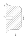
- FIG. 8 is a diagram of a contoured Teflon guide in accordance with an exemplary embodiment of the present disclosure.
- FIG. 1 is a diagram of an ambient frame assembly 100 in accordance with an exemplary embodiment of the present disclosure.
- Ambient frame assembly 100 and the other metal components and assemblies disclosed herein can be formed from steel, aluminum or other suitable materials, by processing such as extrusion, punching, laser cutting, die cutting or other suitable processes.
- Ambient frame assembly 100 includes frame sides 102 , which are disposed between front end assembly 108 and rear end assembly 106 , which are coupled to frame sides 102 by bolts 114 that are attached to end plates 104 and 112 . Rivets, screws, spot welding or other suitable connectors can also or alternatively be used to couple front end assembly 108 and rear end assembly 106 to frame sides 102 . End plates 104 and 112 are connected to frame sides 102 by brazing, TIG welding, arc welding or in other suitable manners. Tabs 110 are attached to front end assembly 108 by brazing, TIG welding, arc welding or in other suitable manners.
- ambient frame assembly 100 is disposed in an ambient environment outside of associated ductwork, and houses a blade assembly and driver (not shown), that is used to open and close a duct in a ventilation passage slide gate.
- Ambient frame assembly 100 is configured to use Teflon guide seals, to help maintain a low-leakage environment for the slide gate.
- FIG. 2 is a diagram of a system frame assembly 200 in accordance with an exemplary embodiment of the present disclosure.
- System frame assembly 200 bolts to ambient frame assembly 100 , and provides the frame for a slide gate that is disposed in an HVAC ventilation passageway.
- System frame assembly 200 includes frame sides 202 , which are disposed between front end assembly 208 and rear frame side 204 .
- Frame sides 202 include a plurality of holes 210 , which are used to secure system frame assembly 200 to HVAC ductwork, and which can be formed by punching, drilling or in other suitable manners.
- Front end assembly 208 is coupled to frame sides 202 by bolts 114 that are attached to end plates 208 . Rivets, screws, spot welding or other suitable connectors can also or alternatively be used to couple front end assembly 208 and rear frame side 204 to frame sides 202 .
- End plates 208 are connected to frame sides 202 by TIG welding, arc welding or in other suitable manners.
- Rear frame side 204 is attached to frame sides 202 by TIG welding, arc welding or in other suitable manners.
- Front bracket 206 is coupled to frame sides 202 by welding or in other suitable manners, and has holes for connection to HVAC ductwork and additional holes for securing a seal made from stainless steel or other suitable materials to system frame assembly 200 .
- system frame assembly 200 is coupled to ambient frame assembly 100 using end plate 208 , which is bolted to end plate 104 of ambient frame assembly 100 , or in other suitable manners.
- Seals are disposed in frame sides 202 and rear frame side 204 , which help to provide a seal between the inner HVAC duct environment and the external ambient environment.
- FIG. 3 is a diagram showing a profile of an ambient frame side 102 in accordance with an exemplary embodiment of the present disclosure.
- Ambient frame side 102 includes major side section 302 and minor side section 304 , which form the sides of the duct interface that connects to the duct that the assembled slide gate is used with.
- Major side section 302 is larger than minor side section 304 in order to allow ambient frame assembly 100 to accommodate a blade drive assembly (not shown), which can be used to remotely control the state of the slide gate (i.e. open or closed).
- Ambient frame side 102 further includes Teflon guide pocket 306 , which is used to hold a Teflon guide assembly (not shown) that is used to allow a blade assembly (not show) to be placed in an air flow path of an air duct, such as to open or close the air flow path in the HVAC ductwork.
- Teflon guide pocket 306 is used to hold a Teflon guide assembly (not shown) that is used to allow a blade assembly (not show) to be placed in an air flow path of an air duct, such as to open or close the air flow path in the HVAC ductwork.
- FIG. 4 is a diagram showing a profile of a system frame side 202 in accordance with an exemplary embodiment of the present disclosure.
- Ambient frame side 202 includes side section 402 and side section 404 , which form the sides of the duct interface that connects to the duct that the assembled slide gate is used with.
- the side sections 402 and 404 of system frame side 202 can be the same size.
- System frame side 202 further includes Teflon guide pocket 406 , which is used to hold a Teflon guide assembly (not shown) that is used to allow a blade assembly (not show) to be placed in an air flow path of an air duct, such as to open or close the air flow path.
- FIG. 5 is a diagram showing ambient end plates 104 and 112 and system end plates 208 in accordance with an exemplary embodiment of the present disclosure.
- System end plate 208 includes Teflon channel slot 502 , which is configured to allow a Teflon guide assembly to be inserted into Teflon guide pocket 406 of system frame side 202 .
- blade slot 504 of ambient end plate 104 is configured to allow a blade (not shown) to be inserted into ambient frame assembly 100 , and channel slot 506 of ambient end frame 112 is not required to form an air-tight fit with a Teflon guide (not shown).
- FIG. 6 is a diagram showing an exploded ambient frame assembly 100 in accordance with an exemplary embodiment of the present disclosure.
- Ambient frame assembly 100 includes Teflon guide seals 602 , which are inserted into Teflon guide pocket 306 of ambient frame sides 102 .
- Blade 604 is then inserted into ambient frame assembly 100 , such as to allow a duct to be selectively opened or closed.
- blade 604 has a length greater than the length of Teflon guide seals 602 , so that blade 604 maintains the position of Teflon guide seals 602 in Teflon guide pockets 306 regardless of whether blade 604 is disposed entirely within ambient frame assembly 100 or system frame assembly 200 .
- FIG. 7 is a diagram showing an exploded system frame assembly 200 in accordance with an exemplary embodiment of the present disclosure.
- System frame assembly 200 includes Teflon guide seals 702 , which have dovetailed ends 706 that are inserted into Teflon guide pocket 406 of system frame sides 202 .
- System frame assembly 200 also includes Teflon guide seal 704 , which includes dovetailed ends 708 that form an airtight seal against dovetailed ends 706 of Teflon guide seals 702 .
- Blade 704 is then inserted into system frame assembly 200 , such as to allow a duct to be selectively opened or closed.
- blade 704 can be the same as blade 604 .
- FIG. 8 is a diagram of a contoured Teflon guide 800 in accordance with an exemplary embodiment of the present disclosure.
- Contoured Teflon guide 800 includes seal 806 , which forms an air tight seal against Teflon guide pockets 306 and 406 of ambient frame side 102 or system frame side 202 , respectively.
- Blade slot 804 allows blade 604 , blade 704 or other suitable components to be easily inserted and withdrawn from ambient frame assembly 100 , system frame assembly 200 or other suitable components.
- Contoured Teflon guide 800 thus helps to prevent blade 604 or blade 704 in a frame assembly (or other suitable components in other suitable assemblies) from becoming stuck or frozen in place, and also provides an air tight seal with ambient frame assembly 100 , system frame assembly 200 or other suitable components that does not require threaded fasteners to be used in an air stream, where such threaded fasteners can leak.
Abstract
Description
Claims (19)
Priority Applications (1)
| Application Number | Priority Date | Filing Date | Title |
|---|---|---|---|
| US14/081,851 US9441853B2 (en) | 2013-11-15 | 2013-11-15 | Teflon pocket slide gate and method of assembly |
Applications Claiming Priority (1)
| Application Number | Priority Date | Filing Date | Title |
|---|---|---|---|
| US14/081,851 US9441853B2 (en) | 2013-11-15 | 2013-11-15 | Teflon pocket slide gate and method of assembly |
Publications (2)
| Publication Number | Publication Date |
|---|---|
| US20150135597A1 US20150135597A1 (en) | 2015-05-21 |
| US9441853B2 true US9441853B2 (en) | 2016-09-13 |
Family
ID=53171871
Family Applications (1)
| Application Number | Title | Priority Date | Filing Date |
|---|---|---|---|
| US14/081,851 Active 2034-03-17 US9441853B2 (en) | 2013-11-15 | 2013-11-15 | Teflon pocket slide gate and method of assembly |
Country Status (1)
| Country | Link |
|---|---|
| US (1) | US9441853B2 (en) |
Cited By (1)
| Publication number | Priority date | Publication date | Assignee | Title |
|---|---|---|---|---|
| US11243008B2 (en) * | 2018-08-21 | 2022-02-08 | Air Distribution Technologies Ip, Llc | Ductwork frame assembly |
Families Citing this family (3)
| Publication number | Priority date | Publication date | Assignee | Title |
|---|---|---|---|---|
| US9377339B2 (en) * | 2012-09-19 | 2016-06-28 | Pius O. Ileogben | Frame support for a hood vent measurement device |
| US9347217B2 (en) * | 2014-04-21 | 2016-05-24 | Green Sentry Solutions Inc. | Insulating cover for wall opening |
| USD1022130S1 (en) * | 2021-04-20 | 2024-04-09 | Blac Inc. | Valve disc |
Citations (21)
| Publication number | Priority date | Publication date | Assignee | Title |
|---|---|---|---|---|
| US2731231A (en) * | 1951-04-10 | 1956-01-17 | John C Garrott | Resilient seal valve |
| US2814244A (en) * | 1954-05-26 | 1957-11-26 | Paul E Hord | Window mounted room air conditioner |
| US2815187A (en) * | 1954-08-02 | 1957-12-03 | Leland S Hamer | Sealed gate valve |
| US3045963A (en) * | 1959-07-17 | 1962-07-24 | Edward M Herrmann | Gate valve |
| US3356334A (en) * | 1965-05-17 | 1967-12-05 | Scaramucci Domer | Gate valve and seal |
| US3799187A (en) * | 1972-10-02 | 1974-03-26 | G Armstrong | Valve seals |
| US3906992A (en) * | 1974-07-02 | 1975-09-23 | John Meredith Leach | Sealed, easily cleanable gate valve |
| US4163544A (en) * | 1977-11-10 | 1979-08-07 | Acf Industries, Incorporated | Two piece composite valve seal ring construction |
| US4182359A (en) | 1977-12-27 | 1980-01-08 | Combustion Engineering, Inc. | Slide gate damper |
| US4193581A (en) * | 1978-06-19 | 1980-03-18 | Acf Industries, Incorporated | Cage for gate valves and method of assembly |
| US4221307A (en) * | 1978-11-22 | 1980-09-09 | Salina Vortex Conveyor Corporation | Method and apparatus for material handling |
| US4253483A (en) | 1978-07-12 | 1981-03-03 | Barron Industries, Inc. | Movable blade damper |
| US4429710A (en) * | 1981-02-17 | 1984-02-07 | Giw Southern Valve, Inc. | Slurry gate valve |
| US4582296A (en) | 1985-03-04 | 1986-04-15 | Lothar Bachmann | Composite blade for dampers for ducts of large cross sectional areas |
| US4700927A (en) | 1986-11-12 | 1987-10-20 | Rodney Hunt Company | Slide gate |
| US4773627A (en) * | 1987-07-06 | 1988-09-27 | Rovang, Inc. | Gate valve |
| US4783048A (en) | 1987-12-17 | 1988-11-08 | St Clair Thomas W | Slide gate damper system |
| US5660371A (en) * | 1995-12-05 | 1997-08-26 | Tomkins Industries, Inc. | Isolation damper with replaceable seal unit |
| US20090114872A1 (en) * | 2003-06-06 | 2009-05-07 | Kongsberg Esco As | Gate valve |
| US20090121173A1 (en) * | 2007-11-14 | 2009-05-14 | Tyco Valves & Controls Lp | Valve assembly having a reinforced valve seat |
| US8251786B2 (en) | 2007-09-03 | 2012-08-28 | Erwin Gasser | Protection device for ventilation ducts |
-
2013
- 2013-11-15 US US14/081,851 patent/US9441853B2/en active Active
Patent Citations (21)
| Publication number | Priority date | Publication date | Assignee | Title |
|---|---|---|---|---|
| US2731231A (en) * | 1951-04-10 | 1956-01-17 | John C Garrott | Resilient seal valve |
| US2814244A (en) * | 1954-05-26 | 1957-11-26 | Paul E Hord | Window mounted room air conditioner |
| US2815187A (en) * | 1954-08-02 | 1957-12-03 | Leland S Hamer | Sealed gate valve |
| US3045963A (en) * | 1959-07-17 | 1962-07-24 | Edward M Herrmann | Gate valve |
| US3356334A (en) * | 1965-05-17 | 1967-12-05 | Scaramucci Domer | Gate valve and seal |
| US3799187A (en) * | 1972-10-02 | 1974-03-26 | G Armstrong | Valve seals |
| US3906992A (en) * | 1974-07-02 | 1975-09-23 | John Meredith Leach | Sealed, easily cleanable gate valve |
| US4163544A (en) * | 1977-11-10 | 1979-08-07 | Acf Industries, Incorporated | Two piece composite valve seal ring construction |
| US4182359A (en) | 1977-12-27 | 1980-01-08 | Combustion Engineering, Inc. | Slide gate damper |
| US4193581A (en) * | 1978-06-19 | 1980-03-18 | Acf Industries, Incorporated | Cage for gate valves and method of assembly |
| US4253483A (en) | 1978-07-12 | 1981-03-03 | Barron Industries, Inc. | Movable blade damper |
| US4221307A (en) * | 1978-11-22 | 1980-09-09 | Salina Vortex Conveyor Corporation | Method and apparatus for material handling |
| US4429710A (en) * | 1981-02-17 | 1984-02-07 | Giw Southern Valve, Inc. | Slurry gate valve |
| US4582296A (en) | 1985-03-04 | 1986-04-15 | Lothar Bachmann | Composite blade for dampers for ducts of large cross sectional areas |
| US4700927A (en) | 1986-11-12 | 1987-10-20 | Rodney Hunt Company | Slide gate |
| US4773627A (en) * | 1987-07-06 | 1988-09-27 | Rovang, Inc. | Gate valve |
| US4783048A (en) | 1987-12-17 | 1988-11-08 | St Clair Thomas W | Slide gate damper system |
| US5660371A (en) * | 1995-12-05 | 1997-08-26 | Tomkins Industries, Inc. | Isolation damper with replaceable seal unit |
| US20090114872A1 (en) * | 2003-06-06 | 2009-05-07 | Kongsberg Esco As | Gate valve |
| US8251786B2 (en) | 2007-09-03 | 2012-08-28 | Erwin Gasser | Protection device for ventilation ducts |
| US20090121173A1 (en) * | 2007-11-14 | 2009-05-14 | Tyco Valves & Controls Lp | Valve assembly having a reinforced valve seat |
Cited By (1)
| Publication number | Priority date | Publication date | Assignee | Title |
|---|---|---|---|---|
| US11243008B2 (en) * | 2018-08-21 | 2022-02-08 | Air Distribution Technologies Ip, Llc | Ductwork frame assembly |
Also Published As
| Publication number | Publication date |
|---|---|
| US20150135597A1 (en) | 2015-05-21 |
Similar Documents
| Publication | Publication Date | Title |
|---|---|---|
| US9441853B2 (en) | Teflon pocket slide gate and method of assembly | |
| US9516784B2 (en) | Electrical switchgear system | |
| BR112018072048A2 (en) | open display refrigerator, kit and method of modifying an open display refrigerator | |
| EP2159514A3 (en) | Multichannel heat exchanger with dissimilar flow | |
| BR112016001706A2 (en) | SPLIT AIR CONDITIONING SYSTEM WITH A SINGLE OUTDOOR UNIT | |
| EP3828473A4 (en) | Refrigerant flow control method and device for air conditioner and computer storage medium | |
| BR102016014630A8 (en) | operator station for a work vehicle | |
| EP3743665A4 (en) | System, components, and methods for air, heat, and humidity exchanger | |
| EP4141339A4 (en) | Multi-split air conditioning system, and refrigerant flow control method therefor | |
| EP3640562A4 (en) | Mode switcher, heat recovery multi-split air conditioning system and control method | |
| US10753638B2 (en) | Ventilation panel with panel silencer for a turbine package enclosure | |
| US20160209075A1 (en) | Duct interface for chilled beam | |
| CN103940006A (en) | Inserting-connection assembly for air conditioner installation | |
| US11690197B2 (en) | Airflow management system that can be fitted to an electrical enclosure | |
| JP6396520B2 (en) | Air conditioner indoor unit | |
| MY196222A (en) | Air Conditioning System | |
| EP3623186A1 (en) | Vehicular air-conditioning device and frame body to be applied thereto | |
| KR20190015798A (en) | Ceiling gel type air filter frame assembly | |
| EP3022498B1 (en) | A duct member and closure assembly for a duct member | |
| JP6758798B2 (en) | Air conditioning system | |
| EP3964765A4 (en) | Air guide device, air conditioner indoor unit with same, and air-conditioning system | |
| US20130306746A1 (en) | Retrofit Flap Damper Assembly System for Cone Type Damper Variable Air Volume Boxes | |
| EP3995774A4 (en) | Air-conditioning unit, heat exchanger, and air conditioner | |
| EP3978857A4 (en) | Flat tube, multi-channel heat exchanger and air conditioning refrigeration system | |
| US20130331024A1 (en) | Retrofit Flap Damper Assembly System for Cone Type Damper Variable Air Volume Boxes |
Legal Events
| Date | Code | Title | Description |
|---|---|---|---|
| AS | Assignment |
Owner name: RUSKIN COMPANY, MISSOURI Free format text: ASSIGNMENT OF ASSIGNORS INTEREST;ASSIGNORS:GORMAN, PAUL T.;BRONSON, MARK W.;REEL/FRAME:031629/0871 Effective date: 20131115 |
|
| STCF | Information on status: patent grant |
Free format text: PATENTED CASE |
|
| AS | Assignment |
Owner name: AIR DISTRIBUTION TECHNOLOGIES IP, LLC, WISCONSIN Free format text: ASSIGNMENT OF ASSIGNORS INTEREST;ASSIGNOR:RUSKIN COMPANY;REEL/FRAME:043129/0642 Effective date: 20170726 |
|
| AS | Assignment |
Owner name: AIR DISTRIBUTION TECHNOLOGIES IP, LLC, WISCONSIN Free format text: ASSIGNMENT OF ASSIGNORS INTEREST;ASSIGNOR:RUSKIN COMPANY;REEL/FRAME:043375/0955 Effective date: 20170816 |
|
| MAFP | Maintenance fee payment |
Free format text: PAYMENT OF MAINTENANCE FEE, 4TH YEAR, LARGE ENTITY (ORIGINAL EVENT CODE: M1551); ENTITY STATUS OF PATENT OWNER: LARGE ENTITY Year of fee payment: 4 |
|
| MAFP | Maintenance fee payment |
Free format text: PAYMENT OF MAINTENANCE FEE, 8TH YEAR, LARGE ENTITY (ORIGINAL EVENT CODE: M1552); ENTITY STATUS OF PATENT OWNER: LARGE ENTITY Year of fee payment: 8 |