US9445115B2 - Coded image system and method thereof - Google Patents
Coded image system and method thereof Download PDFInfo
- Publication number
- US9445115B2 US9445115B2 US14/547,485 US201414547485A US9445115B2 US 9445115 B2 US9445115 B2 US 9445115B2 US 201414547485 A US201414547485 A US 201414547485A US 9445115 B2 US9445115 B2 US 9445115B2
- Authority
- US
- United States
- Prior art keywords
- logic
- image
- mask
- decoding
- doubly
- Prior art date
- Legal status (The legal status is an assumption and is not a legal conclusion. Google has not performed a legal analysis and makes no representation as to the accuracy of the status listed.)
- Active
Links
- 238000000034 method Methods 0.000 title claims description 40
- 239000011159 matrix material Substances 0.000 claims abstract description 55
- 239000013598 vector Substances 0.000 claims abstract description 22
- 230000000007 visual effect Effects 0.000 claims abstract description 11
- 238000003384 imaging method Methods 0.000 claims description 29
- 230000000694 effects Effects 0.000 claims description 24
- 238000004422 calculation algorithm Methods 0.000 claims description 17
- 238000001914 filtration Methods 0.000 claims description 11
- 238000005457 optimization Methods 0.000 claims description 9
- 230000004044 response Effects 0.000 claims description 8
- 238000012935 Averaging Methods 0.000 claims description 7
- 230000036961 partial effect Effects 0.000 claims description 7
- 230000005855 radiation Effects 0.000 claims description 7
- 239000004973 liquid crystal related substance Substances 0.000 claims description 4
- 210000000744 eyelid Anatomy 0.000 claims description 3
- 238000001228 spectrum Methods 0.000 claims description 2
- 230000006870 function Effects 0.000 description 35
- 230000007547 defect Effects 0.000 description 20
- 238000010606 normalization Methods 0.000 description 15
- 238000012545 processing Methods 0.000 description 15
- 238000004088 simulation Methods 0.000 description 15
- 238000013459 approach Methods 0.000 description 13
- 238000005259 measurement Methods 0.000 description 9
- 230000003287 optical effect Effects 0.000 description 8
- 230000006872 improvement Effects 0.000 description 7
- 230000002123 temporal effect Effects 0.000 description 7
- 230000000670 limiting effect Effects 0.000 description 6
- 230000000116 mitigating effect Effects 0.000 description 6
- 230000005540 biological transmission Effects 0.000 description 5
- 238000002474 experimental method Methods 0.000 description 5
- 230000002829 reductive effect Effects 0.000 description 5
- 230000003595 spectral effect Effects 0.000 description 5
- 238000012546 transfer Methods 0.000 description 5
- 230000008901 benefit Effects 0.000 description 4
- 230000008569 process Effects 0.000 description 4
- 230000009467 reduction Effects 0.000 description 4
- 238000012360 testing method Methods 0.000 description 4
- 238000012937 correction Methods 0.000 description 3
- 238000000354 decomposition reaction Methods 0.000 description 3
- 230000001419 dependent effect Effects 0.000 description 3
- 230000035876 healing Effects 0.000 description 3
- 238000011835 investigation Methods 0.000 description 3
- 238000012067 mathematical method Methods 0.000 description 3
- 238000012986 modification Methods 0.000 description 3
- 230000004048 modification Effects 0.000 description 3
- 230000008439 repair process Effects 0.000 description 3
- 238000011160 research Methods 0.000 description 3
- 238000009825 accumulation Methods 0.000 description 2
- 230000009471 action Effects 0.000 description 2
- 238000012152 algorithmic method Methods 0.000 description 2
- 238000004458 analytical method Methods 0.000 description 2
- 238000003491 array Methods 0.000 description 2
- 238000012512 characterization method Methods 0.000 description 2
- 230000001427 coherent effect Effects 0.000 description 2
- 125000004122 cyclic group Chemical group 0.000 description 2
- 238000011161 development Methods 0.000 description 2
- 230000018109 developmental process Effects 0.000 description 2
- 238000005516 engineering process Methods 0.000 description 2
- 239000011521 glass Substances 0.000 description 2
- 239000000463 material Substances 0.000 description 2
- 230000001151 other effect Effects 0.000 description 2
- 230000000737 periodic effect Effects 0.000 description 2
- 238000011084 recovery Methods 0.000 description 2
- 229920006395 saturated elastomer Polymers 0.000 description 2
- MCSXGCZMEPXKIW-UHFFFAOYSA-N 3-hydroxy-4-[(4-methyl-2-nitrophenyl)diazenyl]-N-(3-nitrophenyl)naphthalene-2-carboxamide Chemical compound Cc1ccc(N=Nc2c(O)c(cc3ccccc23)C(=O)Nc2cccc(c2)[N+]([O-])=O)c(c1)[N+]([O-])=O MCSXGCZMEPXKIW-UHFFFAOYSA-N 0.000 description 1
- 101100419874 Caenorhabditis elegans snr-2 gene Proteins 0.000 description 1
- 230000001133 acceleration Effects 0.000 description 1
- 238000007792 addition Methods 0.000 description 1
- 230000015572 biosynthetic process Effects 0.000 description 1
- 230000000903 blocking effect Effects 0.000 description 1
- 239000003086 colorant Substances 0.000 description 1
- 230000001010 compromised effect Effects 0.000 description 1
- 238000011109 contamination Methods 0.000 description 1
- 238000005314 correlation function Methods 0.000 description 1
- 230000002950 deficient Effects 0.000 description 1
- 238000009795 derivation Methods 0.000 description 1
- 230000009977 dual effect Effects 0.000 description 1
- 230000008030 elimination Effects 0.000 description 1
- 238000003379 elimination reaction Methods 0.000 description 1
- 238000011156 evaluation Methods 0.000 description 1
- 229910052736 halogen Inorganic materials 0.000 description 1
- 150000002367 halogens Chemical class 0.000 description 1
- 238000005286 illumination Methods 0.000 description 1
- 238000000126 in silico method Methods 0.000 description 1
- 238000013101 initial test Methods 0.000 description 1
- 230000007774 longterm Effects 0.000 description 1
- 229940050561 matrix product Drugs 0.000 description 1
- 230000010363 phase shift Effects 0.000 description 1
- 230000010287 polarization Effects 0.000 description 1
- 238000004321 preservation Methods 0.000 description 1
- 238000007670 refining Methods 0.000 description 1
- 238000005070 sampling Methods 0.000 description 1
- 230000003068 static effect Effects 0.000 description 1
- 230000002194 synthesizing effect Effects 0.000 description 1
- 230000036962 time dependent Effects 0.000 description 1
- 238000013519 translation Methods 0.000 description 1
- 238000012795 verification Methods 0.000 description 1
Images


Classifications
-
- H—ELECTRICITY
- H04—ELECTRIC COMMUNICATION TECHNIQUE
- H04N—PICTORIAL COMMUNICATION, e.g. TELEVISION
- H04N19/00—Methods or arrangements for coding, decoding, compressing or decompressing digital video signals
- H04N19/44—Decoders specially adapted therefor, e.g. video decoders which are asymmetric with respect to the encoder
-
- H—ELECTRICITY
- H04—ELECTRIC COMMUNICATION TECHNIQUE
- H04N—PICTORIAL COMMUNICATION, e.g. TELEVISION
- H04N19/00—Methods or arrangements for coding, decoding, compressing or decompressing digital video signals
- H04N19/42—Methods or arrangements for coding, decoding, compressing or decompressing digital video signals characterised by implementation details or hardware specially adapted for video compression or decompression, e.g. dedicated software implementation
Definitions
- the present invention relates generally to devices, methods, and systems of coded images. More particularly, an aspect of the present invention relates to lensless imaging and to spatially coded imaging.
- SLM elements are controlled so that the modulated transmission forms an aperture mask, encoding the image with a programmable function.
- the goal of decoding is to use knowledge of the aperture mask programmed with the programmable function to recover the object scene from the encoded image.
- URAs Uniformly Redundant Arrays
- MURAs Modified URAs
- the step of decoding may also include the steps of: filtering the doubly-Toeplitz encoded image to remove pixel-to-pixel response variations caused by one or more of the following: dark noise, fixed-pattern noise, and bad pixels; regularizing the decoding of the doubly-Toeplitz encoded image via a Tikhonov or similar regularization method; and reconstructing the object scene as a decoded image larger than the encoded image.
- the step of decoding may also include the step of iterating the encoded image to reduce numerical round-off errors in inversions of the doubly-Toeplitz matrix in the aperture mask.
- FIG. 1 is a schematic representation of the coded image system of the present invention including an encoding logic portion and a decoding logic portion.
- FIG. 2 is an example of a modified uniformly redundant array (MURA) mask wherein panel (a) is an ideal binary mask, and panel (b) is a collected mask showing effects of diffraction features;
- MURA uniformly redundant array
- FIG. 3A depicts features of Tikhonov-regularized decoding of simulated doubly-Toeplitz-mask encoded images, wherein panel (a) is the object scene, panel (b) is the Toeplitz mask, panel (c) is a partial mask encoding shown with noise, and panel (d) is a partial mask shown without noise
- FIG. 3B is a continuation of FIG. 3A wherein panel (e) is the decoded results of panel (c) and panel (f) is the decoded result of panel (d);
- FIG. 4 is depicts in panel (a) a photograph of an urban scene used as input for simulations and depicts in panel (b) a simulated image output from a noiseless, diffraction-free doubly-Toeplitz coded aperture imager;
- FIG. 5 depicts the simulation of coded-aperture imaging of the scene shown in FIG. 4 , wherein panel (a) shows the image acquired through the doubly-Toeplitz mask shown in panel (b), panel (c) shows the initial decoding, panel (d) depicts the normalized image, and panel (e) depicts the reconstructed image after iteration using Equation;
- FIG. 6 depicts in panel (a) binary aperture mask commanded or programmed on a Spatial Light Modulators SLM and panel (b) depicts its diffracted version;
- FIG. 8A depicts a comparison of two Candidate-Masks compared in terms of their fast Fourier transforms, wherein panel (a) and panel (b) are exemplary masks that meet a 70%—throughput criterion, panel (c) is the natural logarithm of the FFT of the mask-generating sequence of panel (a), and panel (d) is the natural logarithm of the FFT of the mask-generating sequence of panel (b);
- FIG. 8B is a continuation of the comparison made in FIG. 8A wherein panel (e) depicts the decode image obtained through the mask in panel (a) and panel (f) depicts the decoded image obtained through the mask in panel (b);
- FIG. 9 depicts a set up for spectral/angular throughput/extension dependency measurements
- FIG. 11 is a graph showing contrast ratio as a function of wavelength and angle
- FIG. 12 shows effects of inside-the-camera reflections, in three different panel perspectives, namely panel (a), panel (b), and panel (c);
- FIG. 13 depicts decoded images showing reduction in high-spatial-frequency random noise by averaging multiple frames, wherein panel (a) shows a single frame, panel (b) shows ten averaged frames, and panel (c) shows twenty averaged frames;
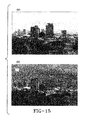
- FIG. 14 depicts equipment set-up for imaging outdoor scenes, viewing the area shown in FIG. 15 , this view looks from downtown Honolulu westward towards Diamondhead mountain (which is mostly obscured by high-rise buildings);
- FIG. 15 depicts in top panel (a) a photograph of an urban object scene and in bottom panel (b) a decoded image acquired with “02” masks encoded on SLM;
- FIG. 16 shows processing flow for coded-aperture image acquisition and decoding
- FIG. 17 depicts in panel (a) raw images from a small square pinhole aperture and in panel (b) depicts images from a coded-aperture mask having the same square pin area as depicted in panel (a);
- FIG. 18 shows processed images from the images obtained and depicted in FIG. 17 , panel (a) is associated with panel (a) in FIG. 17 and panel (b) is associated with panel (b) in FIG. 17 ;
- FIG. 20 shows processed images from the images obtained and depicted in FIG. 19 , panel (a) is associated with panel (a) in FIG. 19 and panel (b) is associated with panel (b) in FIG. 19 ;
- FIG. 21 shows final results of processing real imagery wherein panel (a) depicts the multi-mask with four 90-degree rotations of the “02” mask and wherein panel (b) depicts using a single mask, showing reduction of magnitude of some decoding “ghost” artifacts; and
- FIG. 22 shows in top panel (a) a decoded scene shown in FIG. 21 and at the bottom panel (b) a reference photo of the scene acquired with a conventional camera (note: the clouds are different because the images were acquired at different times).
- a coded image system of the present invention is depicted generally at 100 .
- the image system 100 comprises a physical object scene 102 , an encoding logic 104 , and a decoding logic 106 .
- the encoding logic 104 includes a programmable aperture mask 108 electronically coupled with a camera or imager 110 spaced a distance away from the physical object scene 102 .
- Mask 108 receives light waves partially therethrough, as will be discussed in greater detail below.
- the encoding logic 104 creates an encoded image 112 via a doubly-Toeplitz matrix programmed on mask 108 , the doubly-Toeplitz matrix produced by two one-dimensional vectors as will be described further below.
- the decoding logic 106 is configured to decode the encoded image recovering a visual representation 124 of the object scene from the encoded image.
- the decoding logic includes a filtering logic 114 , a regularization logic 116 , a reconstruction logic 118 , a normalization logic 120 , and a iteration logic 122 .
- the visual representation 124 may be displayed in a monitor 126 or alternatively print media.
- the physical object scene is 102 is non-uniform, including various angles, shapes, lighting, hues, and colors. The order of the processing steps can be varied, and steps may be combined.
- Logic includes but is not limited to hardware, firmware, software and/or combinations of each to perform a function(s) or an action(s), and/or to cause a function or action from another logic, method, and/or system.
- logic may include a software controlled microprocessor, discrete logic like a processor (e.g., microprocessor), an application specific integrated circuit (ASIC), a programmed logic device, a memory device containing instructions, an electric device having a memory, or the like.
- Logic may include one or more gates, combinations of gates, or other circuit components. Logic may also be fully embodied as software. Where multiple logics are described, it may be possible to incorporate the multiple logics into one physical logic. Similarly, where a single logic is described, it may be possible to distribute that single logic between multiple physical logics.
- the doubly-Toeplitz matrix may be realized in a medium selected from a group comprising a programmable aperture mask 108 , a non-programmable aperture mask, a liquid crystal spatial light modulator, an eyelid array, and a self-supporting printed member, however other mediums are entirely possible.
- the doubly-Toeplitz matrix permits radiation through openings defined by the matrix and blocks radiation through non-openings defined by the matrix, wherein the radiation is selected from the group comprising visible light, x-rays, gamma rays, UV light, and infrared light.
- the use of a doubly-Toeplitz matrix in the encoding logic causes the problem of partial mask encoding to be more tractable, thus enabling efficient algorithmic methods for inverting the system transfer function.
- the use of the doubly-Toeplitz matrix in the encoding logic is more accurate than previously known spatial light encoding functions.
- the doubly-Toeplitz matrix encoding allows for the inversion of the encoding function.
- the doubly-Toeplitz matrix are separable and produce fewer zero eigenvalues than decodings with non-separable masks.
- there are fewer random decoding artifacts introduced yielding more accurate reconstruction of the scene being imaged.
- some images that could not be decoded with prior art are now accurately decodable.
- SLM Spatial Light Modulators
- the goal of decoding is to use knowledge of the aperture mask function M to recover the object scene O from the encoded image I.
- an advantage of inverse G matrices which satisfy Equation (3) is that an image of a point source viewed through the mask programmed with function M is simply a scaled version of the decoding mask G, already properly registered to the image I. This removes registration as a source of decoding errors.
- FIG. 2 is an example of a modified uniformly redundant array (MURA) mask wherein panel (a) is an ideal binary mask, and panel (b) is a collected mask showing effects of diffraction features.
- MURA uniformly redundant array
- panel (a) is an ideal binary mask
- panel (b) is a collected mask showing effects of diffraction features.
- the MURA was lithographically deposited as a pattern on a glass slide, so that it was truly binary, either passing (100% transparent) or blocking light (0% transparent).
- the diffracted collected mask in panel (b) shows effects of scattering and diffraction, compromising the self-inverse property.
- even ideal MURAs also have the drawback of having limited utility for extended scenes.
- the matrix M′′ has rows which are shifted copies of the first row, which is constructed from the filter function M by embedding each row of function M into a segment of length C O , padded with zeros for elements C F +1 through C O , then concatenating the segments into a row of length C O *R O , where R O is the number of rows in O. That is,
- M I , C o * i + j ′′ ⁇ M i , j for ⁇ ⁇ j ⁇ the ⁇ ⁇ first ⁇ ⁇ C F ⁇ ⁇ columns 0 for ⁇ ⁇ j ⁇ later ⁇ ⁇ columns .
- M′′ identified as f below in equation 8
- Equation (6) is an improvement on Fourier-transform methods.
- the inverse problem (estimating O from the measurements I) is extremely difficult. This is an ill-posed inversion, inasmuch as there may be many more elements in O than in I. To a degree, this is true of all imagers—real focal planes can collect only a finite number of discrete pixels, and solving ill-posed imaging problems is an active area of research.
- the operations count for solving Equation (11) is on the order of: N Operations, Generalized ⁇ ( r O c O ) 3 . (12)
- This megamatrix approach models object space at a lower resolution, such that the inversion problem is well-posed, and is capable of producing very good results in light of partial mask encoding.
- the inventors have concluded that the approach would be limited to images areas measuring only a few hundred pixels.
- aspects of the present invention sought alternate strategies—seeking improved masks which would have both a large open area (to maximize light-gathering) and mitigate the ill-posed partial-mask problem. Even in cases in which the image resolution is extremely dense, so that sampling is not a limiter of reconstruction accuracy, the finite extent of real focal planes causes the correlation of the mask and object,
- Equation (13) It is possible to specify finite-sized masks that greatly reduce the degree to which the imaging is ill-posed, and render the inversion of Equation (13) tractable.
- M programmable aperture mask 108 programmed with function M
- the matrices M A and M B have Toeplitz forms, in which each row is a copy of the previous row, with the elements shifted by one pixel on each successive
- Equation (15) The difficulty of inversion using Equation (15) is vastly less than for solving Equation (11).
- M A and M B each have the form of a Toeplitz matrix—a matrix in which the elements of each row are identical to the elements in the first row, except for a shift in their column-wise positions, so that each diagonal descending from left to right is constant.
- the term “doubly” refers to twice the normal extent or two times or in two ways, with reference to the two matrices M A and M B that are each in Toeplitz form.
- the coded image system of the present invention includes a computational time period to decode the encoded image, wherein the computational time period is consistent with speeds faster than 10 million pixels per second per Gigaflops of processing power.
- convolutions or correlations can be expressed as multiplications of the object field with Toeplitz, circulant-Toeplitz, or near-Toeplitz matrices.
- the present invention can render the convolution as a pair of much smaller Toeplitz problems.
- Equation (15) there will always be noise arising from effects such as photon counting or read noise, so that the actual inverse problem includes a noise term N, as shown in Equation (15).
- N a noise term
- both the noise and the ill-posedness require a regularization method via regularization logic 116 .
- the matrix products (M A T M A ) and (M B T M B ) are square and symmetric, but are not invertible because their determinants are zero, due to degenerate zero eigenvalues.
- Equation (20) now multiplies O by invertible matrices, so that an estimate of O can be derived from the image:
- O Est ( M A T M A + ⁇ A 2 1 R O ) ⁇ 1 M A T IM B ( M B T M B + ⁇ B 2 1 C O ) ⁇ 1 .
- Equation (21) has a form superficially very similar to the noise-regularization employed with the Fourier-transform method of Equation (5).
- regularization logic 116 includes a special case of the Tikhonov regularization method used in image de-blurring—the parameters ⁇ A and ⁇ B play the dual roles of regularizing the inversion and controlling the effects of noise.
- FIG. 3A and FIG. 3B An example of the effectiveness of the Tikhonov-Toeplitz encoding and decoding aspect of the present invention 100 is shown in FIG. 3A and FIG. 3B .
- This is a complex simulated scene with features spanning its edges, yielding severe partial-mask encodings.
- the encoded images in this case were not reconstructable at all via Fourier methods, even when no noise was present.
- Reconstruction logic 118 via Equation (21) successfully reconstructed not only the central portion of the scene (the part with dimensions equal to the image size), but also extended the reconstruction to the entire range sampled by the encoding mask. With noise added to the imagery, the regularization constants had to be increased (from 1E-10 to 1E+02) to suppress the noise. Increasing the Tikhonov parameters cause blurring of fine image features, but still yielded recognizable decodings.
- the doubly-Toeplitz encodings enable reconstruction logic 118 to digitally reconstruction of scenes larger than the encoded images. This is due to having complete knowledge of the encoding function, and the fact that there are constrained the degrees of freedom to one dimension instead of two, compressing the unknowns by orders of magnitude.
- Successful reconstruction via logic 118 requires that: (1) the imagers 110 have enough dynamic range, that the edges can be “unfolded” from the center without significant loss of information, (2) knowing the encoding functions (either by measurement or by modeling), and (3) constructing Toeplitz masks without zeroes in their spatial-frequency spectra.
- a more-generalized regularization is also possible, deriving non-diagonal regularization matrices based on noise covariances, instead of the diagonal matrices 1 C0 and 1 R0 in Equation (21), after elimination of the non-noise sources of error and interference.
- some scene-dependent non-noise errors such as stray light may present the majority of the errors.
- an image is depicted in panel (a) and the aperture mask 108 programmed with doubly-Toeplitz function M is depicted in panel (b).
- the reconstructed images in panels (c), (d) in FIG. 3A and panels (e), (f) in FIG. 3B show patterns or “artifacts” at their edges within a distance of one mask width (or height) of the border.
- the artifacts in encoded images of uniform (all white) scenes lead the inventors to hypothesize that one can normalize such artifacts out of the reconstructed images.
- the normalization can be accomplished normalizing logic 120 by encoding and decoding a uniform all-white object W to create an estimate W Est that includes the errors in image recovery due to the regularized decoding:
- W Est [M A T M A + ⁇ A 2 1 R O ⁇ R O ] ⁇ 1 ( M A T M A )
- W ( M B T M B ) [ M M T M B + ⁇ B 2 1 C O ⁇ C O ] ⁇ 1 , (22) then dividing the estimated object O Est by W Est element-by-element to obtain a normalized object estimate O Norm :
- O Norm ( i,j ) O Est ( i,j )/ W Est ( i,j ) (23)
- the normalization can also be expressed as multiplication by two normalization matrices D A and D B :
- O Norm D A O Est D B T .
- Equation (27) The normalization in Equation (27) improves the solution, by removing spurious brightness differences accrued as the coded-aperture mask straddles the edge of the image area.
- Equation (21) O Est ⁇ + ⁇ O ⁇ [ 1 ⁇ A 2 S A ]O[ 1 ⁇ B 2 S B ] ⁇
- Equation (31) will eventually diverge because (M A T M A ) and (M B T M B ) are not invertible.
- Equation (37) approaches Equation (31) in a controlled manner.
- Landweber iteration logic 122 and Tikhonov regularization logic 116 seek to solve the ill-posed inverse problem. If the Tikhonov-regularized inversion is performed first, Landweber iteration provides an independently-controlled method for removal of Tikhonov decoding artifacts. The price is that some noise may be re-introduced as the iterations attempt to minimize [I ⁇ ⁇ M A O (n) M B T ], since 1 ⁇ includes noise contributions that Were not encoded by the aperture mask.
- Equation (47) will converge, as long as 0 ⁇ L 2 ⁇ 2. However, the convergent solution is not guaranteed to be correct—the results may be noise-dominated unless we stop the iterations of iteration logic 122 at a suitable point via stopping logic.
- Two general kinds of stopping criteria are possible: a priori criteria, and a posteriori criteria.
- the discrepancy principle can be effective when the noise is known and well-characterized. However, there may be additional random noise sources that cannot be determined in advance by characterizing the image-plane array.
- a posteriori criteria can be implemented with only information from processing a given image.
- a basic a posteriori procedure is to examine the sequence of residuals from Equation (49), and stop the iterations when they begin to increase: if ⁇ r (n) ⁇ 2 > ⁇ r (n ⁇ 1) ⁇ 2 , accept O (n) . (53)
- Equation (55) with Equation (27) as the initial estimate finishes in 1/10 of the iterations required when using Equation (47). All of the Landweber iteration results presented herein are based on Equation (55), with stopping criterion Equation (53).
- FIG. 4 a simulated photograph is depicted in panel (a) in FIG. 4 .
- the results of decoding with Equation (21), together with the normalized version from Equation (39) and the final iterated improvement from Equation (55) with stopping criterion Equation (53) are shown in FIG. 4 , panel (b) for an ideal noiseless case, with intermediate steps from raw imagery through Landweber iteration illustrated in FIG. 5 .
- FIG. 5 depicts the simulation of coded-aperture imaging of the scene shown in FIG. 4 , wherein panel (a) of FIG. 5 shows the image acquired through the doubly-Toeplitz mask 108 shown in panel (b). For clarity, the mask 108 in panel (b) is shown at 3 times its actual size relative to the image.
- a mask-normalization “linen” pattern or artifact is apparent at the edges of the image. This pattern is caused by the mask-scene correlation function ramping up or down at the image edges.
- panel (d) of FIG. 5 the normalized image from Equation (27) is shown. The linen pattern is greatly reduced. The normalized image still shows some residual artifacts due to the need for regularizing the ill-posed decoding problem. Regularization “ghosts” are visible, especially near the edges of the image.
- Panel (e) in FIG. 5 depicts the reconstructed image after Landweber iteration using Equation (55), wherein the results are improved, with reduced artifacts and higher image contrast.
- the Landweber iterations used ⁇ L2 0.1 and converged in 10 iterations.
- One exemplary non-limiting, method comprises the steps of:
- an exemplary method of the present invention comprises the steps of: encoding an image through an aperture mask programmed with a doubly-Toeplitz matrix coupled to a camera to create an encoded image; decoding the encoded image to recover a visual representation of an object scene; displaying the recovered object scene in a monitor, wherein the recovered object scene is larger than the encoded image.
- Equation (15) can also be solved by singular value decomposition, which may be better behaved (with judicious choices of low-eigenvalue cut-offs) than solution via the normal equations.
- singular value decomposition which may be better behaved (with judicious choices of low-eigenvalue cut-offs) than solution via the normal equations.
- Most of the decodings so far have been performed via the normal equations, using the steps outlined in section 5.5.
- the Singular Value Decomposition (SVD) method has potential to provide superior performance, it is outlined in this section, to show a roadmap for an alternate method of decoding, normalizing, and iterating to recover images.
- the matrices UA and UB are composed of orthonomial basis vectors spanning the image space
- the vectors VA (also referred to as Vector A) and VB (also referred to as Vector B) are composed of orthonormal vectors spanning the object space
- the vectors A and B are diagonal matrices of eigenvalues. While Equation (58) appears invertible, it actually must also be regularized when the problem is ill-posed and noisy.
- O Est V A Z A U A T IU B Z B V B T
- O (0) O Norm
- SVD D A V A Z A U A T IU B Z B V B T D B T
- the elements of the normalization matrices corresponding to Equation (26) are:
- aspects of the present invention set out to refine simulation codes to better model the system performance, in order to: verify that the doubly-Toeplitz property was preserved in diffracted masks, verify the requirements for laboratory-collected masks to be valid, quickly evaluate candidate aperture masks, and provide a means of synthesizing decoding matrices when collected masks are not available.
- aspects of the present invention added diffraction to the simulation code. This is particularly straightforward for a collection of identical rectangular apertures placed at points on a rectangular-grid SLM.
- I O and I P denote intensity fields at the object and image planes, respectively, and let E O denote the complex optical field at the object plane.
- the diffracted intensity in a pixel at location (i,j) on the image plane is:
- Equation (65) shows that, if the raw aperture mask is an outer product of two one-dimensional vectors A and B, then the effects of the diffracted mask can still be expressed as an operation of a pair of Toeplitz matrices. Thus, a doubly-Toeplitz aperture mask 108 will yield a doubly-Toeplitz encoding, even when there is significant diffraction.
- Equation (65) Those skilled in the art will see by inspecting Equation (65) that the image encoding described by Equation (65) is decomposable into A and B vectors which can be used to synthesize decoding masks. It will thus be appreciated that doubly-Toeplitz aperture masks remain doubly-Toeplitz when diffracted. Further, if the surface reflecting the light is microscopically rough, the illumination can be coherent or laser-like, and Equation (65) would still hold true.
- aspects of the present invention are correctly simulating the diffraction.
- the experiments included a collected image a synthetic image of a point source through a single large square aperture.
- the experiments also included a collected image and a synthetic image through a similarly-sized aperture created with SLM.
- Agreement between lab data and the diffraction model is high. Within the precision with which one can measure the experimental parameters, the agreement between model and data is excellent.
- aspects of the present invention include a simulation tool which one can use to evaluate candidate aperture masks in silico.
- the agreement between model and data also gives us confidence that we can use lab-collected masks as decoding filters.
- Diffracted masks were also modeled, and compared to “collected masks”—images of a point-source viewed through the spatial-coding masks. It was verified that the collected masks decompose into outer products of diffracted 1-dimensional functions, in accord with Equation (64). A diffracted 1-dimensional mask is compared to the un-diffracted version in FIG. 6 . This figure also illustrates a drawback to using MURA masks: diffraction alters the actual mask pattern and makes it non-binary, destroying the self-inversion in Equation (3).
- the simulation model includes random noise and non-diffraction blur, as well as light leakage through the “off” pixels of the SLM.
- This light leakage required the diffraction simulator, and has a significant impact on the image contrast, since even a small leakage of power implies a much larger optical-field leakage, since the power is proportional to the square of the field. For example, a 1% power leakage implies an optical field variation of 10%.
- Random noise is generated primarily by photon-counting (shot noise), thermal dark noise, and pixel read/reset noise. Aspects of the present invention are currently treating this as Gaussian-distributed with an empirically-determined standard deviation ⁇ noise . For the light levels at which our system is currently being tested, ⁇ noise is approximately 0.23% of the mean signal level.
- Non-diffraction blur can arise from inhomogeneities in the liquid-crystal material of the SLM pixels, and from portions of the pixel circuitry which are not 100% opaque.
- We currently model these scattering sources with a Gaussian point-spread function with width ⁇ scattering .
- the blur seems to subtend only a few focal-plane pixels.
- Both ⁇ noise and ⁇ scattering can be estimated by fitting the model to laboratory-collected data, and further refined (if needed) via parameter optimization algorithms.
- doubly-Toeplitz mask selection is a key determinant of the quality of images recovered from coded-aperture cameras.
- the larger the mask the more degenerate the ill-posed inversion and the greater the decoding artifacts.
- the smaller the mask the lower the light-gathering ability and the longer an exposure time is required.
- Criteria we have considered include:
- each vector A and B need to have at least 70.7% throughput.
- mask selection involves searching through a list of random candidate masks, then applying thresholds on the Fourier transforms to select those which might have desirable image-formation properties, followed by testing with simulated encoding and decoding to quantify mask quality.
- the search space is enormous. For example, a 100-element mask vector has 2 ⁇ 100 possible binary combinations, the vast majority of which will not be useful.
- the 32-element 1-dimensional mask was adapted from the temporal processing results of Agrawal et al. A few other masks that meet the 70%—throughput criterion are compared in terms of their fast Fourier transform algorithm (FFTs) and their encoding/decoding performance in FIG. 8A and FIG. 8B .
- FFTs fast Fourier transform algorithm
- FIG. 8A and FIG. 8B depict a comparison of two candidate masks.
- panel (a) and panel (b) are exemplary masks that meet a 70%—throughput criterion
- panel (c) is the natural logarithm of the FFT of the mask-generating sequence of panel (a)
- panel (d) is the natural logarithm of the FFT of the mask-generating sequence of panel (b).
- FIG. 8B is a continuation of the comparison made in FIG. 8A wherein panel (e) depicts the decode image obtained through the mask in panel (a) and panel (f) depicts the decoded image obtained through the mask in panel (b).
- the edge artifacts resemble the mask pattern, and higher-resolution masks seem to be more susceptible to noise.
- aspects of the present invention have developed an automated image-quality scoring program which can be used with the coded-aperture simulator to quantify the performance of masks and algorithms.
- the next step is to develop a mask-candidate-selection algorithm that can efficiently narrow the search space of all possible masks, so that only the most likely candidates are fed into the automated assessment algorithm.
- the final assessments of masks will be done via imaging real scenes and using human-in-the loop scoring.
- Equation (65) requires knowledge of the spectral throughputs and responsivities.
- FIG. 9 a lab experiment was created to gain deeper understanding on how the SLM 140 polarizer responses were affecting imaging and decoding for lensless imager with mask 108 ( FIG. 1 ) from a halogen lamp 143 measured by spectrometer 145 .
- the setup is shown FIG. 9 , with results presented in FIG. 10 and FIG. 11 .
- FIG. 10 presents the results of the % of light transmission of white and black SLM 140 pixels at normal incidence (0°; vertical in FIG. 9 ).
- the vertical axis represents the transmission percentage and the horizontal axis represents the wavelengths.
- Contrast ratio 144 a is associated with angle measurement 142 of 0°. Contrast ratio 144 b is associated with angle measurement 142 of 10°. Contrast ratio 144 c is associated with angle measurement 142 of 20°. Contrast ratio 144 d is associated with angle measurement 142 of 30°. Contrast ration 144 e is associated with angle measurement 142 of 40°.
- aspects of the present invention note that the decoding performance real SLM data was not as good as the modeled performance, especially for larger masks.
- One aspect of the present invention eliminated focal plane noise, diffraction, and other effects via modeling and experiment. The major discrepancies were traced to un-modeled internal reflections inside the camera, probably due to reflections from the micro-lens array projected on the inside of the inner surface of the camera window.
- FIG. 12 An example of an image showing numerous reflections is shown in FIG. 12 .
- Panel (a) in FIG. 12 depicts image flat acquired by looking into an integrating sphere through the SLM, with the “Ag08” mask pattern commanded. This mask 108 subtends about 248 SLM elements, or about 1200 focal-plane pixels.
- Panel (b) the flat band-passed to remove the low-spatial-frequency components of the flat. Many small apparent defects in the flat are visible.
- the inset identified in panel (c) shows an expanded view of a portion of the band-passed flat, showing several images of the aperture (circled). These reflections appear at the same locations in both the flats acquired by looking into an integrating sphere and in the images of extended scenes, though with scene-dependent amplitudes, requiring additional image-processing steps.
- reflections were not encoded by the mask, they cannot be decoded, and attempting to decode them yields image artifacts which resemble those produced by defects on the image plane.
- one aspect of the present invention has modified focal-plane-defect-healing algorithms to knock out the reflections. This requires acquiring camera “flat’ images with the spatial light modulator in place and commanded to provide an aperture of the dimensions of the mask to be used. Acquiring the flat in that manner allows the locations of the stray reflections to be mapped and stored for use in the defect-healing algorithms. Mitigating the stray-light artifacts in this way is a short-term fix, since it possesses the drawback of removing larger areas as the mask grows, which introduces a new set of errors and artifacts.
- Stray-light artifacts also appear in the collected-mask images. These are images of a point source collected with the coded-aperture mask in place. Normally, the point-source images would provide decoding masks which automatically include scattering and diffraction. Unfortunately, the stray-light contaminated collected masks also required image healing, and provided inferior performance to modeled masks. Thus, we used simulations to create model masks in which we included diffraction, multiple-scattering blur and light leakage.
- the modeled masks were used to decode all of the real imagery shown in this report.
- the permanent fix will be introducing camera hardware modifications to reduce or eliminate the stray-light reflections.
- decoding real data is that of degraded data, such as produced by bad pixels, defects in the optics, etc. In a classical imaging system, these will manifest as dark or bright pixels, or small, sometimes blurry, dark spots in the focused imaged. In decoded images, the information content of a single bad pixel or a dark spot on the image will be redistributed through the decoded image, resulting in mask-shaped artifacts in the final image. In order to avoid these, we first conduct a “repair” of the collected raw image.
- One aspect of the present invention implemented a two-step repair process. First, identify bad pixels as part of a radiometric calibration. Then, collect and average a series of 100 image frames using the same exposure times as for actual imaging, but with the aperture fully occluded, to collect a “dark” file that indicates dark current biases. This is followed by averaging 100 frames collected viewing into an integrating sphere to collect a “flat” file, which indicates non-uniformity of response across the focal plane. The choice of 100 frames for the statistical averaging is desired by not required. In general, longer series yield more-precise characterizations of defects, while shorter series minimize the effects of time-dependent drifts in response. An system designer skilled in the art would select the optimal number of frames for a particular application.
- Hot and saturated pixels are identified from dark images—images collected with the aperture occluded—by identifying all pixels having a light-free output value greater than some threshold value.
- a threshold of twice the local neighbor median for that pixel using a 5 ⁇ 5 pixel neighborhood centered on each pixel.
- Cold and dead pixels, as well as potential additional hot pixels are identified from “flat” imagery; any pixel for which the value is outside an acceptable range from the local neighborhood median value is flagged as bad.
- a map of bad pixels is generated to include all pixels flagged above.
- the bad-pixel map is generated once from calibration data, then applied to each collected raw image to mitigate image defects.
- Most defects are single-pixel defects; values for these pixels are replaced with the mean values from the four adjacent neighbors.
- the size and shape of the neighborhood used for healing single-pixel defects is flexible.
- Four neighbors may be expanded to six, eight, ten or more.
- values are linearly interpolated across the bad pixel region using the nearest adjacent good pixel values for that image. Values are interpolated across the shorter dimension of the bad cluster first, this repeated as necessary until the defective cluster is filled in with interpolated replacement values.
- This simple approach relies on the assumption that the correct raw image (encoded) content is generally smoothly varying, and defects are typically singleton pixels.
- other healing algorithms are entirely possible, the aforementioned algorithm is offered by way of example.
- Another aspect of the present invention have found that, in addition to bad pixels on the imaging focal plane, other image defects (e.g. due to dirt or internal reflections cause similar decoding artifacts). These defects tend to involve small, contiguous clusters of pixels, but have lower contrast than bad pixel defects. These are mitigated by making a second “bad pixel” map after the initial repair, but using much lower tolerances for the deviation from local neighborhood medians values and a larger neighborhood. As before, the defects are mapped, and repaired using linear interpolation across the shortest dimension of the defect.
- FIG. 13 depicts the effectiveness, comparing 1, 10, and 20-frame averages of the same scene.
- the averaging depicted in FIG. 13 is done on the raw images, before any flattening, correction, or decoding was applied.
- Panel (a) shows a single frame
- panel (b) shows ten averaged frames
- panel (c) shows twenty averaged frames.
- aspects of the present invention assessed the various sources of errors in coded-aperture imaging, as outlined in Table 2.
- the effects of diffraction are primarily to (a) increase the ill-posed degeneracy by requiring larger decoding matrices in Equation (27), and (b) complicate mask selection by invalidating the assumption that the masks are binary.
- Toeplitz Mask Moderate Adds image “ghosts” 1. Use the smallest mask Selection and artifacts at edges consistent with the lighting of decoded images. conditions. 2. Average multiple images with different mask orientations 3. Develop improved mask- search methods to identify optimal masks. Image-Plane Major “checkerboard” 1. Flatten the image to reduce Defects artifacts in decoded pixel-to-pixel response variations. (bad pixels, hot image 2. Filter out & “heal” bad pixels in pixels, cold pixels) raw image before decoding In-band Light Major Low contrast 1. Short-term: Normalize with Leakage Stray Light decodings with mask- “SLM flats” and apply aggressive and Reflections imprint artifacts defect-healing algorithms. Inside Camera 2. Long-term: implement hardware mods to reduce stray light and reduce residual throughput of “off” SLM elements.
- the Tikhonov regularization constant ⁇ helps reduce noise in the reconstruction, but setting this value too high causes undue blurring of the reconstructed scene. While a value for a can be chosen using visual assessment of decoded image quality, the selection process can be automated using a numerical minimization routine.
- Temporal coded-aperture imaging is also an ill-posed problem amenable via Tikhonov-regularized inversion of a spatial transform of the temporal transfer function.
- the temporal regularization constant ⁇ Temporal for this inversion will be distinct from the spatial values, and can be separately optimized to optimize decodings.
- the optimal value of ⁇ Temporal will depend on the noise and on the temporal code. Unlike the spatial problem, it will also depend on the speed acceleration of the imager, making an automated approach for parameter optimization even more valuable.
- FIG. 14 one exemplary experimental setup is shown in FIG. 14 .
- the camera 110 was on the 12th floor of the First Hawaiian building in Honolulu, Hi., approximately 45 meters above the ground, and looking west towards the city skyline.
- the camera 110 includes programmable SLM aperture mask 108 operatively coupled thereto including a doubly-Toeplitz matrix programmed thereon.
- the SLM aperture mask 108 programmed with the doubly-Toeplitz matrix is controlled by a SLM pattern command computer 107 .
- the camera 110 had a green-bandpass filter to reject wavelengths that are not adequately blocked by the “off” pixels of the SLM, as illustrated in FIG. 10 .
- black pixels “leak” light at about 1.4% of white pixels over the range 500 nm-650 nm.
- the on/off contrast is lower. It is recommended that a filter is used that limits the incoming light to 450 nm ⁇ 650 nm.
- the decoding logic 106 is shown self-contained within a computer in accordance with the definition of “logic” as defined above.
- a method 1600 may include the step of encoding an image through an aperture mask programmed with a doubly-Toeplitz matrix, shown at 1602 . Then, there is correcting the encoded image through flattening and darkness reduction, shown at 1604 . Then there is, removing bad pixels, shown at 1606 . Next there is, filtering the encoded image to denoise the encoded image, shown at 1608 . Then there is, decoding the encoded image, shown at 1610 . And then, normalizing the decoded image, shown at 1612 .
- the de-noising step can be either single-frame de-noising, or de-noising by adding multiple raw images before decoding. Since the stray-light interference limits currently limits the effectiveness of single-frame de-noising, FIG. 15 used a 20-frame average, with the raw images averaged together before application of flat, dark, and defect corrections.
- coded-aperture imaging is based on the principle of collecting overlapping images from many pinholes, it is fair to ask how coded-aperture images compare to pinhole-camera images.
- aspects of the present invention used pinholes with the same un-obstructed area as the coded-aperture mask.
- the small “02” coded-aperture masks spanned 62 SLM elements in each direction, with 43 “on” elements.
- the inventors compared a 43 ⁇ 43 pinhole camera (a square mask with all elements turned on in a 43 ⁇ 43 area) to the 02 coded aperture.
- the raw unprocessed images for each are of similar (blurry and unrecognizable) quality, as shown in FIG. 17 .
- FIG. 17 both images in panel (a) and panel (b), doubly-Toeplitz processing was applied using synthetic masks which included diffraction and light leakage. The images were also normalized, then Landweber-iterated until convergence.
- the coded aperture image provides superior resolution (panel (b) in FIG. 18 ).
- aspects of the present invention also collected data using a large coded-aperture, the “08” version, spanning 248 ⁇ 248 SLM elements.
- the pinhole with equal collecting area spanned 172 ⁇ 172 elements.
- the raw data are shown in FIG. 19
- the decoded images are shown in FIG. 20 .
- the difference in recovered image quality between pinhole images (panel (a) in FIG. 20 ) and coded apertures (panel (b) in FIG. 20 ) is greater at the larger aperture sizes.
- the coded-aperture processing developed of the present invention can be leveraged to greatly improve the images output from pinhole cameras. In particular, it is possible to mitigate diffraction and geometric blur to recover images from raw data that would be otherwise unrecognizable.
- the spatial-frequency content of the image is less compromised by a coded-aperture containing elements of several sizes than by a single large uniform aperture.
- the coded aperture better preserves high spatial frequencies.
- the dynamic range of the recovered images falls as the size of the largest contiguous area in the aperture grows.
- a coded aperture mask provides better image resolution than a rectangular “pinhole” aperture. Also, as the overall aperture size increases, coded-aperture imagers maintain resolution and image quality better than do pinhole cameras.
- FIG. 21 shows final results of processing real imagery with multi-mask (four 90-degree rotations of the “02” mask) in panel (a) versus using a single mask in panel (b), showing reduction of magnitude of some decoding “ghost” artifacts.
- FIG. 22 shows in top panel (a) a decoded scene shown of FIG. 21 and at the bottom panel (b) a reference photo of the scene acquired with a conventional camera (note: the clouds are different because the images were acquired at different times).
- coded image system 100 may permit computed imaging to be completely done without the need for a traditional camera lenses.
- doubly-Toeplitz coded apertures may be realized, with programmable or fixed non-programmable masks fabricated from a variety of materials, and applied for radiation of any wavelength, from gamma rays to radio waves. Therefore, the present invention should not be limited to any single embodiment, but rather construed in breadth and scope in accordance with the recitation of the appended claims. Additionally, the term “programmable” also includes a sequence of selectable fixed-pattern apertures, each of the doubly-Toeplitz type.
- a doubly-Toeplitz mask 108 is an example of an optical system in which the operation of the optics create an image that can be modeled separately in the two axes of an imager, so that the two-dimensional OTF (optical transfer function) can be treated as a sequential (x-axis then y-axis, or y-axis then x-axis) application of two one-dimensional OTFs.
- Separable optics have the advantage of having blur functions that can be processed very quickly to improve the quality of the images.
- the mathematical methods outlined herein are applicable to any system having separable OTFs, and would improve the quality of images recovered from such systems.
Abstract
Description
I=M
O Estimated =G
was easily derivable from M itself. For example, for Uniformly Redundant Array masks:
where the last equality holds if the noise is uncorrelated with the signal. With regularization, recognizable decodings of laboratory images were achieved with both non-programmable lithographic and programmable-SLM masks.
Where I1 and O1 are 1-dimensional vectors created by concatenating the rows of I and O respectively, such that:
I1C
where CI and CO are the numbers of columns in I and O respectively. The matrix M″ has rows which are shifted copies of the first row, which is constructed from the filter function M by embedding each row of function M into a segment of length CO, padded with zeros for elements CF+1 through CO, then concatenating the segments into a row of length CO*RO, where RO is the number of rows in O. That is,
For example, consider a 3×3 filter function M″ (identified as f below in equation 8), and a 4×4 object scene O filtered to yield a 2×2 image I.
M″ T I1=(M″ T M″+α 21R
where 1R
N Operations, Generalized∝(r O c O)3. (12)
to be ill-posed, since the extent of the object O is unbounded, and the programmed mask function M conveys information about O into the limited area of I. The general problem of estimating the elements of O from the observations I is very difficult, even if M is perfectly known. While the forward problem of generating an image from the object O is unique, the inverse problem may have multiple solutions of varying fidelity. In particular, the MURA (Modified Uniformly Redundant Array) masks used for code-aperture imaging yield extremely ill-posed problems when imaging extended scenes.
M(i,j)=A(i)B(j), (14)
and the convolution Equation (13) can be written simply as a matrix product:
I=M A OM B T +N, (15)
wherein a noise term N has been added.
| TABLE 1 |
| Relationship of dimensions of the collected image, the encoding filter |
| mask and the object area contributing to the image. |
| Matrix | rows | columns |
| Coded-aperture Mask Filter M | rF | cF |
| Image on Focal Plane I | rI | cI |
| Object area O | rO = (rI + rF − 1) | cO = (cI + cF − 1) |
| Left Toeplitz mask MA | rI | rO |
| Right Toeplitz mask MB | cI | cO |
N Operations, Doubly-Toeplitz∝[(r O)3+(c O)3]. (18)
M A T IM B=(M A T M A)O(M B T M B)T +M A T NM B. (19)
M A T IM B≈(M A T M A+αA 21R
where 1R
O Est=(M A T M A+αA 21R
W Est =[M A T M A+αA 21R
then dividing the estimated object OEst by WEst element-by-element to obtain a normalized object estimate ONorm:
O Norm(i,j)=O Est(i,j)/W Est(i,j) (23)
The normalization can also be expressed as multiplication by two normalization matrices DA and DB:
O Norm =D A O Est D B T. (24)
This is because the all-white matrix W can be expressed as an outer product of two one-dimensional vectors of constant value, which in turn allows the normalization estimate to be decomposed into an outer product of two 1-dimensional matrices:
W Est(i,j)=W A(i)W B(i). (25)
The normalization matrices DA and DB each have identical columns, given by:
The decoded and normalized object estimate is then:
O Norm D A(MA T M A+αA 2)−1 M A T IM B((MB T M B+αB 2)T)−1D B T. (27)
The normalization in Equation (27) improves the solution, by removing spurious brightness differences accrued as the coded-aperture mask straddles the edge of the image area.
O=O Est δ +{O−[1−αA 2 S A ]O[1−αB 2 S B]} (28)
Where the noise-perturbed object estimate is:
O Est δ =O Est−(S A M A T)N(M B S B), (29)
where;
S A=(M A T M A+αA 2)−1, and
S B=(M B T M B+αB 2)−1. (30)
Equation (28) suggests pursuing a strategy of successively substituting estimates of O into the right-hand side, iterating:
O (n+1) =O Est δ +{O (n)−[1−αA 2 S A ]O (n)[1−αB 2 S B]}, with (31)
O (0) =O Est δ. (32)
For well-posed problems, this is essentially the strategy of iterative improvement to reduce numerical round-off errors in inversions. However, for ill-posed problems, Equation (31) will eventually diverge because (MA TMA) and (MB TMB) are not invertible. To see this consider the one-dimensional case: Y=MAX and the iterative solution:
X n+1 =X n +[X Est δ−[1−αA 2 S A ]X n ]=X Est δ+αA 2 S A X n, with (33)
X Est δ=[1−αA 2 S A ]Y+S A M A T N. (34)
After N iterations, the solution is:
And as N approaches infinity the series sums so that:
-
- 1) choosing the constants α2 A and α2 B so that (αA 2SA) and (αB 2SB) have norms that are small,
- 2) selecting masks for which it is possible to implement 1), and
- 3) judicious selection of a criterion for stopping the iterations, truncating the series before noise swamps the solution.
The analogous 1-dimensional case, Equation (36), then becomes:
which does converge. In the limit γ→1, Equation (37) approaches Equation (31) in a controlled manner.
O Norm =D A S A M A T IM B S B D B T, (39)
The iterative solution becomes:
O (n+1) =O (n) +D A S A M A T [I δ −M A O (n) M B T ]M B S B D B, with (40)
O (0) =O Norm, and with the convergence factor included, we have: (41)
O (n+1) =O (n)+γ2 D A S A M A T [I δ −M A O (n) M B T ]M B S B D B. (42)
The matrices DA and DB enforce normalization as the iterations proceed.
O (n+1) =O (n) +M A T(δA P A)[I δ −M A O (n) M B T](εB P B T)M B, (43)
εA P A
Thus,
1) Set the starting estimate according to Equation (27)
O (0) =O Est δ =P A M A T I δ M B P B with (45)
P A =D A S A and P B =D B S B, (46)
2) Then iterate using:
O (n+1) =O (n)+εL 2 P A M A T [I δ −M A O (n) M B T ]M B P B. (47)
R (n) =M A T [I δ −M A O (n) M B T ]M B, with norm (48)
Let the sum-squared noise be given by:
Then the iterations should be stopped when:
∥r (n)∥2<4δ2. (51)
σ2(i,j)=[M A T
projecting the image noise into the space of the object. This may be effective when the random noise is dominated by pixel-to-pixel variations in the imager electronics (read noise, dark noise, digitizer noise, etc.).
A Posteriori Criteria
if ∥r (n)∥2 >∥r (n−1)∥2, accept O (n). (53)
We also tested an alternate stopping criterion limiting the maximum value of the residuals:
O (n+1) =O (n)+εL 2 D A S A M A T [I δ −M A O (n) M B T ]M B S B D B+αn(O (n) −O (0)), (55)
with
αn=1/(4+n). (56).
-
- 1) encoding an image with a doubly-
Toeplitz masks 108 to encode the images; - 2) flattening and correcting the raw images for focal-plane noise and in-camera effects such as stray light via filtering logic 114;
- 3) computing the decoding mask from the diffraction simulation from (65) via
regularization logic 116 andreconstruction logic 118; - 4) apply Equation (27), using the computed mask, to obtain the initial estimate via
normalization logic 120; - 5) refining the solution using the modified Landweber iterations, Equation (55) with the stopping criterion (53) via
iteration logic 122; - 6) if necessary, repeat steps 4) and 5) to optimize the Tikhonov regularization parameters αA 2 and αB 2.
- 1) encoding an image with a doubly-
M A=(U AΣA V A T), and M B=(V BΣB U B T), so that: (57)
I=(U AΣA V A T)O(V BΣB U B T). (58)
Z A(i,j)=δi,j/(σ2 A(j)+αA 2) and (59)
Z B(i,j)=δi,j/(σ2 B(j)+αB 2), (60)
where σ2 A and σ2 B are the diagonals of ΣA and ΣB. The estimated object is then given by:
O Est =V A Z A U A T IU B Z B V B T, and (61)
the normalized version of the SVD solution is:
O (0) =O Norm,SVD =D A V A Z A U A T IU B Z B V B T D B T,
where the elements of the normalization matrices corresponding to Equation (26) are:
The derivation of iterative improvement is the same as the normal equations, yielding:
O (n+1) =O (n)+εL 2 D A V A Z A U A T [I δ −M A O (n) M B T ]U B Z B V B T D B T+αn(O (n) −O (0)). (63)
The current inversions and iterations rely on solving the normal Equation (20), via normalizations (39), and iterations (47). Future application of the SVD methodology may apply to problems to which improvements beyond the normal equations are required.
The angular brackets < > in Equation (64) indicate the ensample average over quantities therein. Unless k=k′ and l=l′, the optical fields E0 (k,l) and E0 (k′,l′) are statistically uncorrelated, so that the ensemble averages of their products vanish, simplifying Equation (64) to produce Equation (65):
The parameters in Equations (64) through (67) are:
(aX, aY)=Aperture opening sizes (pX, pY)=Aperture pitch, >(aX, aY)(ΔxP, ΔyP)=Image-plane pixel pitch
A, B=vectors of weights of mask elements in the x and y directions
R=Range from aperture mask to object plane
fP=range from aperture mask to image plane
λ=wavelength of light.
Examination of Equation (65) shows that, if the raw aperture mask is an outer product of two one-dimensional vectors A and B, then the effects of the diffracted mask can still be expressed as an operation of a pair of Toeplitz matrices. Thus, a doubly-
| TABLE 2 |
| Summary of Effects of Modeled Error Sources |
| Name | Impact | Manifestation | Mitigation | |
| Diffraction | Minor | Adds blur | Increase size of decoding mask | |
| to capture diffraction patterns | ||||
| SLM-element | Minor | Adds blur | Add blur term to decoding mask | |
| throughput & | ||||
| scattering variations | ||||
| Image-Plane | Moderate | Reduced contrast in | Median filter the raw image | |
| Random Noise | decoded images | before decoding | ||
| Spectral throughput | Moderate | Increased |
1. Add a band-pass filter to the | |
| of SLM | through “off” pixels | optics | ||
| outside |
2. Compute diffracted mask over | |||
| multiple wavelengths in band | ||||
| Angular | Moderate | Decoded scenes | Post-decoding image flattening. | |
| Dependence | how an intensity roll- | This is | ||
| of SLM Throughput | off with angle | impeded by the presence of stray | ||
| light inside the camera. | ||||
| Toeplitz Mask | Moderate | Adds image “ghosts” | 1. Use the smallest mask | |
| Selection | and artifacts at edges | consistent with the lighting | ||
| of decoded images. | conditions. | |||
| 2. Average multiple images with | ||||
| |
||||
| 3. Develop improved mask- | ||||
| search methods to identify | ||||
| optimal masks. | ||||
| Image-Plane | Major | “checkerboard” | 1. Flatten the image to reduce | |
| Defects | artifacts in decoded | pixel-to-pixel response variations. | ||
| (bad pixels, | image | 2. Filter out & “heal” bad pixels in | ||
| pixels, cold pixels) | raw image before decoding | |||
| In-band Light | | Low contrast | 1. Short-term: Normalize with | |
| Leakage Stray Light | decodings with mask- | “SLM flats” and apply aggressive | ||
| and Reflections | imprint artifacts | defect-healing algorithms. | ||
| Inside |
2. Long-term: implement | |||
| hardware mods to reduce stray | ||||
| light and reduce residual | ||||
| throughput of “off” SLM elements. | ||||
-
- determined that the generalized mask problem is computationally very difficult, perhaps making the use of MURA masks impractical for extended-scene coded aperture imaging;
- identified a new class of doubly-Toeplitz coded-
aperture masks 108 that make the problem of partial mask encoding much more tractable, enabling efficient algorithmic methods for inverting the system transfer function; - developed multiple regularized de-coding approaches for doubly-
Toeplitz masks 108 and improved the decoding quality so that images the inventors obtain with a programmable spatial-light modulatorfunction M mask 108 are of better quality than those the inventors were obtaining with non-programmable lithographic masks; - developed a simulation program which includes realistic diffraction effects, and verified it has sufficient fidelity to the laboratory data that may be uses to guide mask selection and algorithm optimization, the simulation also includes system PSF, noise, and scattering;
- investigated how the optical properties of transmissive SLMs affect or limit the effectiveness of coded-aperture imaging, and developed mitigation methods;
- applied the doubly-Toeplitz encoding and decoding methodologies to programmable coded-aperture imagers and successfully decoded imagery from extended outdoor scenes in natural light; and
- while the present invention has been described in connection with the preferred embodiments of the various figures, it is to be understood that other similar embodiments may be used or modifications and additions may be made to the described embodiment for performing the same function of the present invention without deviating there from.
Claims (24)
Priority Applications (1)
| Application Number | Priority Date | Filing Date | Title |
|---|---|---|---|
| US14/547,485 US9445115B2 (en) | 2013-11-21 | 2014-11-19 | Coded image system and method thereof |
Applications Claiming Priority (2)
| Application Number | Priority Date | Filing Date | Title |
|---|---|---|---|
| US201361906958P | 2013-11-21 | 2013-11-21 | |
| US14/547,485 US9445115B2 (en) | 2013-11-21 | 2014-11-19 | Coded image system and method thereof |
Publications (2)
| Publication Number | Publication Date |
|---|---|
| US20150139560A1 US20150139560A1 (en) | 2015-05-21 |
| US9445115B2 true US9445115B2 (en) | 2016-09-13 |
Family
ID=53173390
Family Applications (1)
| Application Number | Title | Priority Date | Filing Date |
|---|---|---|---|
| US14/547,485 Active US9445115B2 (en) | 2013-11-21 | 2014-11-19 | Coded image system and method thereof |
Country Status (1)
| Country | Link |
|---|---|
| US (1) | US9445115B2 (en) |
Cited By (7)
| Publication number | Priority date | Publication date | Assignee | Title |
|---|---|---|---|---|
| US20160371819A1 (en) * | 2015-06-17 | 2016-12-22 | Canon Kabushiki Kaisha | Image processing apparatus, image pickup apparatus, image processing method, and non-transitory computer-readable storage medium for estimating blur |
| US20160371820A1 (en) * | 2015-06-17 | 2016-12-22 | Canon Kabushiki Kaisha | Image processing apparatus, image pickup apparatus, image processing method, and non-transitory computer-readable storage medium for estimating blur |
| US11132757B2 (en) | 2019-08-27 | 2021-09-28 | Rosemount Aerospace Inc. | Secure image transmission |
| US11303839B1 (en) | 2020-10-05 | 2022-04-12 | Raytheon Company | Coded aperture focal plane array |
| US11624588B2 (en) | 2020-06-25 | 2023-04-11 | Simmonds Precision Products, Inc. | Coded aperture seeker for navigation |
| US11734877B2 (en) | 2021-02-25 | 2023-08-22 | Samsung Electronics Co., Ltd. | Method and device for restoring image obtained from array camera |
| US11871131B2 (en) | 2021-08-06 | 2024-01-09 | Raytheon Company | Foveal compressive upsampling |
Families Citing this family (38)
| Publication number | Priority date | Publication date | Assignee | Title |
|---|---|---|---|---|
| JP6549240B2 (en) * | 2015-01-29 | 2019-07-24 | ウィリアム マーシュ ライス ユニバーシティWilliam Marsh Rice University | Lensless imaging system using an image sensor with one or more attenuation layers |
| US10557923B2 (en) * | 2015-02-25 | 2020-02-11 | The Government Of The United States Of America, As Represented By The Secretary Of The Navy | Real-time processing and adaptable illumination lidar camera using a spatial light modulator |
| CN108141294B (en) * | 2015-07-12 | 2020-03-03 | 凝聚技术股份有限公司 | OFDM-compatible orthogonal time-frequency-space communication system |
| US10989821B2 (en) * | 2016-12-14 | 2021-04-27 | Nanyang Technological University | Singer product apertures |
| US10996104B2 (en) | 2017-08-23 | 2021-05-04 | Rosemount Aerospace Inc. | Terminal-imaging seeker using a spatial light modulator based coded-aperture mask |
| US11818401B2 (en) | 2017-09-14 | 2023-11-14 | Apple Inc. | Point cloud geometry compression using octrees and binary arithmetic encoding with adaptive look-up tables |
| US10861196B2 (en) | 2017-09-14 | 2020-12-08 | Apple Inc. | Point cloud compression |
| US10897269B2 (en) | 2017-09-14 | 2021-01-19 | Apple Inc. | Hierarchical point cloud compression |
| US10909725B2 (en) | 2017-09-18 | 2021-02-02 | Apple Inc. | Point cloud compression |
| US11113845B2 (en) | 2017-09-18 | 2021-09-07 | Apple Inc. | Point cloud compression using non-cubic projections and masks |
| US10699444B2 (en) | 2017-11-22 | 2020-06-30 | Apple Inc | Point cloud occupancy map compression |
| US10607373B2 (en) | 2017-11-22 | 2020-03-31 | Apple Inc. | Point cloud compression with closed-loop color conversion |
| US10909726B2 (en) | 2018-04-10 | 2021-02-02 | Apple Inc. | Point cloud compression |
| US11010928B2 (en) | 2018-04-10 | 2021-05-18 | Apple Inc. | Adaptive distance based point cloud compression |
| US10939129B2 (en) | 2018-04-10 | 2021-03-02 | Apple Inc. | Point cloud compression |
| US10909727B2 (en) | 2018-04-10 | 2021-02-02 | Apple Inc. | Hierarchical point cloud compression with smoothing |
| US11017566B1 (en) | 2018-07-02 | 2021-05-25 | Apple Inc. | Point cloud compression with adaptive filtering |
| US11044478B2 (en) * | 2018-07-02 | 2021-06-22 | Apple Inc. | Compression with multi-level encoding |
| US11202098B2 (en) | 2018-07-05 | 2021-12-14 | Apple Inc. | Point cloud compression with multi-resolution video encoding |
| US11012713B2 (en) | 2018-07-12 | 2021-05-18 | Apple Inc. | Bit stream structure for compressed point cloud data |
| US11386524B2 (en) | 2018-09-28 | 2022-07-12 | Apple Inc. | Point cloud compression image padding |
| US11367224B2 (en) | 2018-10-02 | 2022-06-21 | Apple Inc. | Occupancy map block-to-patch information compression |
| US11430155B2 (en) | 2018-10-05 | 2022-08-30 | Apple Inc. | Quantized depths for projection point cloud compression |
| CN109829874B (en) * | 2019-01-30 | 2023-06-30 | 西安电子科技大学 | SAR image fusion method based on frame theory |
| US11057564B2 (en) | 2019-03-28 | 2021-07-06 | Apple Inc. | Multiple layer flexure for supporting a moving image sensor |
| US11627314B2 (en) | 2019-09-27 | 2023-04-11 | Apple Inc. | Video-based point cloud compression with non-normative smoothing |
| US11562507B2 (en) | 2019-09-27 | 2023-01-24 | Apple Inc. | Point cloud compression using video encoding with time consistent patches |
| US11538196B2 (en) | 2019-10-02 | 2022-12-27 | Apple Inc. | Predictive coding for point cloud compression |
| US11895307B2 (en) | 2019-10-04 | 2024-02-06 | Apple Inc. | Block-based predictive coding for point cloud compression |
| CA3063946A1 (en) * | 2019-10-08 | 2021-04-08 | Rosemount Aerospace Inc. | Terminal-imaging seeker using a spatial light modulator based coded-aperture mask |
| US11069035B2 (en) * | 2019-12-17 | 2021-07-20 | Bae Systems Information And Electronic Systems Integration Inc. | Method for double-exposure image processing |
| US11798196B2 (en) | 2020-01-08 | 2023-10-24 | Apple Inc. | Video-based point cloud compression with predicted patches |
| US11625866B2 (en) | 2020-01-09 | 2023-04-11 | Apple Inc. | Geometry encoding using octrees and predictive trees |
| US11620768B2 (en) | 2020-06-24 | 2023-04-04 | Apple Inc. | Point cloud geometry compression using octrees with multiple scan orders |
| US11615557B2 (en) | 2020-06-24 | 2023-03-28 | Apple Inc. | Point cloud compression using octrees with slicing |
| KR20230096116A (en) * | 2020-11-06 | 2023-06-29 | 루카스 산토스 페레이라 | Systems and methods for image convolution |
| US11948338B1 (en) | 2021-03-29 | 2024-04-02 | Apple Inc. | 3D volumetric content encoding using 2D videos and simplified 3D meshes |
| CN114690236B (en) * | 2022-06-01 | 2022-08-02 | 成都理工大学 | Fast ghost imaging method aiming at beam intensity distribution |
Citations (12)
| Publication number | Priority date | Publication date | Assignee | Title |
|---|---|---|---|---|
| US4190861A (en) * | 1976-09-07 | 1980-02-26 | U.S. Philips Corporation | Method and arrangement for redundancy-reducing picture coding |
| US5946038A (en) * | 1996-02-27 | 1999-08-31 | U.S. Philips Corporation | Method and arrangement for coding and decoding signals |
| US6064689A (en) * | 1998-07-08 | 2000-05-16 | Siemens Aktiengesellschaft | Radio communications receiver and method of receiving radio signals |
| US6292592B1 (en) * | 1998-10-19 | 2001-09-18 | Raytheon Company | Efficient multi-resolution space-time adaptive processor |
| US7466575B2 (en) * | 2006-05-12 | 2008-12-16 | Anobit Technologies Ltd. | Memory device programming using combined shaping and linear spreading |
| US20090290806A1 (en) * | 2008-05-22 | 2009-11-26 | Micron Technology, Inc. | Method and apparatus for the restoration of degraded multi-channel images |
| US20090297058A1 (en) * | 2008-05-30 | 2009-12-03 | Ralph Thomas Hoctor | Method and apparatus for image reconstruction for a synthetic aperture gamma ray imager |
| US20110170144A1 (en) * | 2010-01-11 | 2011-07-14 | Yogesh Sankarasubramaniam | Document processing |
| US20130083312A1 (en) * | 2011-09-30 | 2013-04-04 | Inview Technology Corporation | Adaptive Search for Atypical Regions in Incident Light Field and Spectral Classification of Light in the Atypical Regions |
| US20130194481A1 (en) * | 2012-01-29 | 2013-08-01 | Michael Golub | Snapshot spectral imaging based on digital cameras |
| US20140118398A1 (en) * | 2012-10-31 | 2014-05-01 | Sony Computer Entertainment Europe Limited | Apparatus and method for augmented reality |
| US20150073263A1 (en) * | 2012-03-19 | 2015-03-12 | Koninklijke Philips N.V. | Magnetic resonance image reconstruction method with respiratory mot detection during sampling of central and peripheral k-space areas |
-
2014
- 2014-11-19 US US14/547,485 patent/US9445115B2/en active Active
Patent Citations (12)
| Publication number | Priority date | Publication date | Assignee | Title |
|---|---|---|---|---|
| US4190861A (en) * | 1976-09-07 | 1980-02-26 | U.S. Philips Corporation | Method and arrangement for redundancy-reducing picture coding |
| US5946038A (en) * | 1996-02-27 | 1999-08-31 | U.S. Philips Corporation | Method and arrangement for coding and decoding signals |
| US6064689A (en) * | 1998-07-08 | 2000-05-16 | Siemens Aktiengesellschaft | Radio communications receiver and method of receiving radio signals |
| US6292592B1 (en) * | 1998-10-19 | 2001-09-18 | Raytheon Company | Efficient multi-resolution space-time adaptive processor |
| US7466575B2 (en) * | 2006-05-12 | 2008-12-16 | Anobit Technologies Ltd. | Memory device programming using combined shaping and linear spreading |
| US20090290806A1 (en) * | 2008-05-22 | 2009-11-26 | Micron Technology, Inc. | Method and apparatus for the restoration of degraded multi-channel images |
| US20090297058A1 (en) * | 2008-05-30 | 2009-12-03 | Ralph Thomas Hoctor | Method and apparatus for image reconstruction for a synthetic aperture gamma ray imager |
| US20110170144A1 (en) * | 2010-01-11 | 2011-07-14 | Yogesh Sankarasubramaniam | Document processing |
| US20130083312A1 (en) * | 2011-09-30 | 2013-04-04 | Inview Technology Corporation | Adaptive Search for Atypical Regions in Incident Light Field and Spectral Classification of Light in the Atypical Regions |
| US20130194481A1 (en) * | 2012-01-29 | 2013-08-01 | Michael Golub | Snapshot spectral imaging based on digital cameras |
| US20150073263A1 (en) * | 2012-03-19 | 2015-03-12 | Koninklijke Philips N.V. | Magnetic resonance image reconstruction method with respiratory mot detection during sampling of central and peripheral k-space areas |
| US20140118398A1 (en) * | 2012-10-31 | 2014-05-01 | Sony Computer Entertainment Europe Limited | Apparatus and method for augmented reality |
Non-Patent Citations (13)
| Title |
|---|
| Agrawal, Amit, and Ramesh Raskar. "Resolving Objects At Higher Resolution From a Single Motion-Blurred Image." TR2007-036, Jul. 2007, pp. 1-8. |
| Egger, H. "On the Convergence of Modified Landweber Iteration for Nonlinear Inverse Problems." Apr. 14, 2010. pp. 1-16. http://www.aices.rwth-aachen.de:8080/aices/preprint/documentsold/AICES-2010-9.pdf. |
| Elfving, Tommy and Touraj Nikazad, Stopping Rules for Landweber-Type Iteration, 2007, Inverse Problems 23, published Jun. 13, 2007, IOP Publishing Ltd. pp. 1417-1432. |
| Fenimore, E. E., and T. M. Cannon. "Coded Aperture Imaging With Uniformly Redundant Arrays." Applied Optics, vol. 17, No. 3, Feb. 1, 1978, pp. 337-347. |
| Gottesman, Stephan R., and E. E. Fenimore. "New Family of Binary Arrays for Coded Aperture Imaging." Applied Optics, vol. 28, No. 20, Oct. 15, 1989. pp. 4344-4352. |
| Hadamard, Jacques, "Sur Les Problemes Aux Derivees Partielles Et Leur Signification Physique", Princeton University Bulletin, vol. 13, No. 4, Apr. 1902. pp. 49-52. http://babel.hathitrust.org/cgi/pt?id=chi.095582186; view=1up;seq=65. |
| Hansen, Christian. "Deconvolution and Regularization With Toeplitz Matrices." Numerical Algorithms 29 (2002), pp. 323-378. |
| Kimitei, Symon, Algorithms for Toeplitz Matrices and Their Applications to Image Reconstruction. http://www.slideserve.com/vern/by-symon-kimitei-spring-2005. Spring, 2005. 29 pages. |
| Kimura et al. A Hybrid Approach to High Resolution Two Dimensional Spectrum Analysis, IEEE Transantions on Acoustics, Speech, and Signal Processing, vol. Assp-35, No. 7, Jul. 1987. * |
| Raskar, Ramesh, Amit Agrawal, and Jack Tumblin. "Coded Exposure Photography: Motion Deblurring Using Fluttered Shutter." TR2006-124, Jul. 2006, pp. 795-804. |
| Vetterling, William T., Saul A. Teukolsky, and William H. Press. Numerical Recipes in C: The Art of Scientific Computing, Section 18.4, Inverse Problems and the Use of a Priori Information. Press Syndicate of the University of Cambridge, 1992, pp. 804-808. |
| Vetterling, William T., Saul A. Teukolsky, and William H. Press. Numerical Recipes in C: The Art of Scientific Computing, Section 2.11, Is Matrix Inversion an N3 Process? Press Syndicate of the University of Cambridge, 1992, pp. 102-104. |
| Vetterling, William T., Saul A. Teukolsky, and William H. Press. Numerical Recipes in C: The Art of Scientific Computing, Section 2.5, Iterative Improvement of a Solution to Linear Equations, Press Syndicate of the University of Cambridge, 1992, pp. 55-58. |
Cited By (9)
| Publication number | Priority date | Publication date | Assignee | Title |
|---|---|---|---|---|
| US20160371819A1 (en) * | 2015-06-17 | 2016-12-22 | Canon Kabushiki Kaisha | Image processing apparatus, image pickup apparatus, image processing method, and non-transitory computer-readable storage medium for estimating blur |
| US20160371820A1 (en) * | 2015-06-17 | 2016-12-22 | Canon Kabushiki Kaisha | Image processing apparatus, image pickup apparatus, image processing method, and non-transitory computer-readable storage medium for estimating blur |
| US9996908B2 (en) * | 2015-06-17 | 2018-06-12 | Canon Kabushiki Kaisha | Image processing apparatus, image pickup apparatus, image processing method, and non-transitory computer-readable storage medium for estimating blur |
| US10002411B2 (en) * | 2015-06-17 | 2018-06-19 | Canon Kabushiki Kaisha | Image processing apparatus, image pickup apparatus, image processing method, and non-transitory computer-readable storage medium for estimating blur |
| US11132757B2 (en) | 2019-08-27 | 2021-09-28 | Rosemount Aerospace Inc. | Secure image transmission |
| US11624588B2 (en) | 2020-06-25 | 2023-04-11 | Simmonds Precision Products, Inc. | Coded aperture seeker for navigation |
| US11303839B1 (en) | 2020-10-05 | 2022-04-12 | Raytheon Company | Coded aperture focal plane array |
| US11734877B2 (en) | 2021-02-25 | 2023-08-22 | Samsung Electronics Co., Ltd. | Method and device for restoring image obtained from array camera |
| US11871131B2 (en) | 2021-08-06 | 2024-01-09 | Raytheon Company | Foveal compressive upsampling |
Also Published As
| Publication number | Publication date |
|---|---|
| US20150139560A1 (en) | 2015-05-21 |
Similar Documents
| Publication | Publication Date | Title |
|---|---|---|
| US9445115B2 (en) | Coded image system and method thereof | |
| US10861143B2 (en) | Method and apparatus for reconstructing hyperspectral image using artificial intelligence | |
| Tan et al. | Compressive hyperspectral imaging via approximate message passing | |
| US9225889B1 (en) | Photographic image acquisition device and method | |
| US7440637B2 (en) | Method and apparatus for image mosaicing | |
| Delbracio et al. | The non-parametric sub-pixel local point spread function estimation is a well posed problem | |
| CN110692233B (en) | Imaging device, image processing device, imaging system, image processing method, and recording medium | |
| US10366480B2 (en) | Super-resolution systems and methods | |
| US9307208B2 (en) | System and method for solving inverse imaging problems | |
| US9607362B2 (en) | Compressive imaging using approximate message passing with denoising | |
| US20080075386A1 (en) | Extended Depth of Field Using a Multi-Focal Length Lens with a Controlled Range of Spherical Aberration and a Centrally Obscured Aperture | |
| Dave et al. | Solving inverse computational imaging problems using deep pixel-level prior | |
| Kotera et al. | Blind deconvolution with model discrepancies | |
| Zeng et al. | Robust reconstruction with deep learning to handle model mismatch in lensless imaging | |
| Hu et al. | Practical snapshot hyperspectral imaging with DOE | |
| Delbracio et al. | Non-parametric sub-pixel local point spread function estimation | |
| Lee et al. | Robust all-in-focus super-resolution for focal stack photography | |
| Jeon et al. | Multisampling compressive video spectroscopy | |
| Sciacchitano | Image reconstruction under non-Gaussian noise | |
| Delbracio | Two problems of digital image formation: recovering the camera point spread function and boosting stochastic renderers by auto-similarity filtering | |
| Tezaur et al. | A system for estimating optics blur psfs from test chart images | |
| Soulez et al. | Joint deconvolution and demosaicing | |
| Galvis-Carreno | Coded aperture design in compressive spectral imaging | |
| Kar | Computational spectral imaging techniques using diffractive lenses and compressive sensing | |
| Scrymgeour et al. | Advanced Imaging Optics Utilizing Wavefront Coding. |
Legal Events
| Date | Code | Title | Description |
|---|---|---|---|
| AS | Assignment |
Owner name: BAE SYSTEMS INFORMATION AND ELECTRONIC SYSTEMS INT Free format text: ASSIGNMENT OF ASSIGNORS INTEREST;ASSIGNORS:DEWEERT, MICHAEL J.;FARM, BRIAN P.;TOPPING, MILES;SIGNING DATES FROM 20141114 TO 20141118;REEL/FRAME:034209/0347 |
|
| STCF | Information on status: patent grant |
Free format text: PATENTED CASE |
|
| MAFP | Maintenance fee payment |
Free format text: PAYMENT OF MAINTENANCE FEE, 4TH YEAR, LARGE ENTITY (ORIGINAL EVENT CODE: M1551); ENTITY STATUS OF PATENT OWNER: LARGE ENTITY Year of fee payment: 4 |
|
| MAFP | Maintenance fee payment |
Free format text: PAYMENT OF MAINTENANCE FEE, 8TH YEAR, LARGE ENTITY (ORIGINAL EVENT CODE: M1552); ENTITY STATUS OF PATENT OWNER: LARGE ENTITY Year of fee payment: 8 |