US9445486B2 - Energy dissipative tubes - Google Patents
Energy dissipative tubes Download PDFInfo
- Publication number
- US9445486B2 US9445486B2 US14/971,278 US201514971278A US9445486B2 US 9445486 B2 US9445486 B2 US 9445486B2 US 201514971278 A US201514971278 A US 201514971278A US 9445486 B2 US9445486 B2 US 9445486B2
- Authority
- US
- United States
- Prior art keywords
- tubing
- resin layer
- energy dissipative
- conductive
- layer
- Prior art date
- Legal status (The legal status is an assumption and is not a legal conclusion. Google has not performed a legal analysis and makes no representation as to the accuracy of the status listed.)
- Active
Links
- 229920005989 resin Polymers 0.000 claims abstract description 139
- 239000011347 resin Substances 0.000 claims abstract description 139
- 239000010935 stainless steel Substances 0.000 claims abstract description 14
- 229910001220 stainless steel Inorganic materials 0.000 claims abstract description 14
- 229920001169 thermoplastic Polymers 0.000 claims abstract description 11
- 239000004020 conductor Substances 0.000 claims description 9
- PXHVJJICTQNCMI-UHFFFAOYSA-N Nickel Chemical compound [Ni] PXHVJJICTQNCMI-UHFFFAOYSA-N 0.000 claims description 8
- 229910052782 aluminium Inorganic materials 0.000 claims description 7
- XAGFODPZIPBFFR-UHFFFAOYSA-N aluminium Chemical compound [Al] XAGFODPZIPBFFR-UHFFFAOYSA-N 0.000 claims description 7
- RYGMFSIKBFXOCR-UHFFFAOYSA-N Copper Chemical compound [Cu] RYGMFSIKBFXOCR-UHFFFAOYSA-N 0.000 claims description 6
- 229910052802 copper Inorganic materials 0.000 claims description 6
- 239000010949 copper Substances 0.000 claims description 6
- BQCADISMDOOEFD-UHFFFAOYSA-N Silver Chemical compound [Ag] BQCADISMDOOEFD-UHFFFAOYSA-N 0.000 claims description 5
- PCHJSUWPFVWCPO-UHFFFAOYSA-N gold Chemical compound [Au] PCHJSUWPFVWCPO-UHFFFAOYSA-N 0.000 claims description 5
- 229910052737 gold Inorganic materials 0.000 claims description 5
- 239000010931 gold Substances 0.000 claims description 5
- 229910052709 silver Inorganic materials 0.000 claims description 5
- 239000004332 silver Substances 0.000 claims description 5
- 229910052759 nickel Inorganic materials 0.000 claims description 4
- 239000006229 carbon black Substances 0.000 claims description 3
- 229920000049 Carbon (fiber) Polymers 0.000 claims description 2
- 239000004917 carbon fiber Substances 0.000 claims description 2
- 239000013528 metallic particle Substances 0.000 claims 6
- 239000002245 particle Substances 0.000 claims 5
- 229910052751 metal Inorganic materials 0.000 description 98
- 239000002184 metal Substances 0.000 description 98
- 239000011888 foil Substances 0.000 description 48
- 230000000149 penetrating effect Effects 0.000 description 33
- 238000007789 sealing Methods 0.000 description 33
- 238000000034 method Methods 0.000 description 25
- 239000000463 material Substances 0.000 description 15
- -1 polyethylene Polymers 0.000 description 7
- 229920000642 polymer Polymers 0.000 description 7
- XEEYBQQBJWHFJM-UHFFFAOYSA-N Iron Chemical compound [Fe] XEEYBQQBJWHFJM-UHFFFAOYSA-N 0.000 description 6
- 230000008878 coupling Effects 0.000 description 6
- 238000010168 coupling process Methods 0.000 description 6
- 238000005859 coupling reaction Methods 0.000 description 6
- 238000004519 manufacturing process Methods 0.000 description 6
- 230000005611 electricity Effects 0.000 description 5
- 150000002739 metals Chemical class 0.000 description 5
- 229910001369 Brass Inorganic materials 0.000 description 4
- 239000010951 brass Substances 0.000 description 4
- 238000005520 cutting process Methods 0.000 description 4
- 239000007789 gas Substances 0.000 description 4
- 239000007788 liquid Substances 0.000 description 4
- 229920001343 polytetrafluoroethylene Polymers 0.000 description 4
- 239000004810 polytetrafluoroethylene Substances 0.000 description 4
- 238000012360 testing method Methods 0.000 description 4
- 239000004698 Polyethylene Substances 0.000 description 3
- 239000000956 alloy Substances 0.000 description 3
- 238000009434 installation Methods 0.000 description 3
- 229910052742 iron Inorganic materials 0.000 description 3
- 229920000573 polyethylene Polymers 0.000 description 3
- 229920001187 thermosetting polymer Polymers 0.000 description 3
- 238000012546 transfer Methods 0.000 description 3
- 229910000906 Bronze Inorganic materials 0.000 description 2
- 229920002943 EPDM rubber Polymers 0.000 description 2
- RTAQQCXQSZGOHL-UHFFFAOYSA-N Titanium Chemical compound [Ti] RTAQQCXQSZGOHL-UHFFFAOYSA-N 0.000 description 2
- 239000000853 adhesive Substances 0.000 description 2
- 230000001070 adhesive effect Effects 0.000 description 2
- 229910045601 alloy Inorganic materials 0.000 description 2
- 239000010974 bronze Substances 0.000 description 2
- 239000003990 capacitor Substances 0.000 description 2
- 150000001875 compounds Chemical class 0.000 description 2
- 230000006835 compression Effects 0.000 description 2
- 238000007906 compression Methods 0.000 description 2
- KUNSUQLRTQLHQQ-UHFFFAOYSA-N copper tin Chemical compound [Cu].[Sn] KUNSUQLRTQLHQQ-UHFFFAOYSA-N 0.000 description 2
- 229920001971 elastomer Polymers 0.000 description 2
- 229920000840 ethylene tetrafluoroethylene copolymer Polymers 0.000 description 2
- 239000003063 flame retardant Substances 0.000 description 2
- 238000009413 insulation Methods 0.000 description 2
- 229910001092 metal group alloy Inorganic materials 0.000 description 2
- 239000010955 niobium Substances 0.000 description 2
- GUCVJGMIXFAOAE-UHFFFAOYSA-N niobium atom Chemical compound [Nb] GUCVJGMIXFAOAE-UHFFFAOYSA-N 0.000 description 2
- 229920003023 plastic Polymers 0.000 description 2
- 239000004033 plastic Substances 0.000 description 2
- BASFCYQUMIYNBI-UHFFFAOYSA-N platinum Chemical compound [Pt] BASFCYQUMIYNBI-UHFFFAOYSA-N 0.000 description 2
- 239000004800 polyvinyl chloride Substances 0.000 description 2
- 239000002002 slurry Substances 0.000 description 2
- 239000000126 substance Substances 0.000 description 2
- 239000010936 titanium Substances 0.000 description 2
- 229910052719 titanium Inorganic materials 0.000 description 2
- 238000009834 vaporization Methods 0.000 description 2
- 230000008016 vaporization Effects 0.000 description 2
- 229910000975 Carbon steel Inorganic materials 0.000 description 1
- 229920000271 Kevlar® Polymers 0.000 description 1
- 208000025274 Lightning injury Diseases 0.000 description 1
- 229910001209 Low-carbon steel Inorganic materials 0.000 description 1
- 229910018487 Ni—Cr Inorganic materials 0.000 description 1
- OAICVXFJPJFONN-UHFFFAOYSA-N Phosphorus Chemical compound [P] OAICVXFJPJFONN-UHFFFAOYSA-N 0.000 description 1
- 229910000831 Steel Inorganic materials 0.000 description 1
- 208000027418 Wounds and injury Diseases 0.000 description 1
- HCHKCACWOHOZIP-UHFFFAOYSA-N Zinc Chemical compound [Zn] HCHKCACWOHOZIP-UHFFFAOYSA-N 0.000 description 1
- QCWXUUIWCKQGHC-UHFFFAOYSA-N Zirconium Chemical compound [Zr] QCWXUUIWCKQGHC-UHFFFAOYSA-N 0.000 description 1
- 230000009471 action Effects 0.000 description 1
- 150000001336 alkenes Chemical class 0.000 description 1
- RREGISFBPQOLTM-UHFFFAOYSA-N alumane;trihydrate Chemical compound O.O.O.[AlH3] RREGISFBPQOLTM-UHFFFAOYSA-N 0.000 description 1
- 238000013459 approach Methods 0.000 description 1
- 239000004760 aramid Substances 0.000 description 1
- 229920003235 aromatic polyamide Polymers 0.000 description 1
- 230000033228 biological regulation Effects 0.000 description 1
- 230000015572 biosynthetic process Effects 0.000 description 1
- 239000006227 byproduct Substances 0.000 description 1
- 229910052793 cadmium Inorganic materials 0.000 description 1
- BDOSMKKIYDKNTQ-UHFFFAOYSA-N cadmium atom Chemical compound [Cd] BDOSMKKIYDKNTQ-UHFFFAOYSA-N 0.000 description 1
- 239000010962 carbon steel Substances 0.000 description 1
- 230000015556 catabolic process Effects 0.000 description 1
- 238000003486 chemical etching Methods 0.000 description 1
- VNNRSPGTAMTISX-UHFFFAOYSA-N chromium nickel Chemical compound [Cr].[Ni] VNNRSPGTAMTISX-UHFFFAOYSA-N 0.000 description 1
- 239000003086 colorant Substances 0.000 description 1
- 238000004891 communication Methods 0.000 description 1
- 230000001010 compromised effect Effects 0.000 description 1
- 239000002482 conductive additive Substances 0.000 description 1
- 229920003020 cross-linked polyethylene Polymers 0.000 description 1
- 239000004703 cross-linked polyethylene Substances 0.000 description 1
- 238000013461 design Methods 0.000 description 1
- 229910003460 diamond Inorganic materials 0.000 description 1
- 239000010432 diamond Substances 0.000 description 1
- 239000000806 elastomer Substances 0.000 description 1
- 238000009760 electrical discharge machining Methods 0.000 description 1
- 230000008030 elimination Effects 0.000 description 1
- 238000003379 elimination reaction Methods 0.000 description 1
- 238000004146 energy storage Methods 0.000 description 1
- QHSJIZLJUFMIFP-UHFFFAOYSA-N ethene;1,1,2,2-tetrafluoroethene Chemical group C=C.FC(F)=C(F)F QHSJIZLJUFMIFP-UHFFFAOYSA-N 0.000 description 1
- 238000001125 extrusion Methods 0.000 description 1
- 239000000835 fiber Substances 0.000 description 1
- 239000012530 fluid Substances 0.000 description 1
- 229920002313 fluoropolymer Polymers 0.000 description 1
- 238000010348 incorporation Methods 0.000 description 1
- 239000012212 insulator Substances 0.000 description 1
- 230000003993 interaction Effects 0.000 description 1
- 230000001788 irregular Effects 0.000 description 1
- VTHJTEIRLNZDEV-UHFFFAOYSA-L magnesium dihydroxide Chemical compound [OH-].[OH-].[Mg+2] VTHJTEIRLNZDEV-UHFFFAOYSA-L 0.000 description 1
- 229910001862 magnesium hydroxide Inorganic materials 0.000 description 1
- 239000000347 magnesium hydroxide Substances 0.000 description 1
- 230000014759 maintenance of location Effects 0.000 description 1
- 239000002923 metal particle Substances 0.000 description 1
- 229910052758 niobium Inorganic materials 0.000 description 1
- JRZJOMJEPLMPRA-UHFFFAOYSA-N olefin Natural products CCCCCCCC=C JRZJOMJEPLMPRA-UHFFFAOYSA-N 0.000 description 1
- 238000001259 photo etching Methods 0.000 description 1
- 230000021715 photosynthesis, light harvesting Effects 0.000 description 1
- 229910052697 platinum Inorganic materials 0.000 description 1
- 229920000098 polyolefin Polymers 0.000 description 1
- 229920000915 polyvinyl chloride Polymers 0.000 description 1
- 238000003825 pressing Methods 0.000 description 1
- 238000012545 processing Methods 0.000 description 1
- 239000000047 product Substances 0.000 description 1
- 230000001681 protective effect Effects 0.000 description 1
- 238000004064 recycling Methods 0.000 description 1
- 230000009467 reduction Effects 0.000 description 1
- 238000011160 research Methods 0.000 description 1
- 239000005060 rubber Substances 0.000 description 1
- 229920002379 silicone rubber Polymers 0.000 description 1
- 239000004945 silicone rubber Substances 0.000 description 1
- 239000000779 smoke Substances 0.000 description 1
- 229910000679 solder Inorganic materials 0.000 description 1
- 239000010959 steel Substances 0.000 description 1
- 229910000601 superalloy Inorganic materials 0.000 description 1
- 210000004243 sweat Anatomy 0.000 description 1
- 229920002994 synthetic fiber Polymers 0.000 description 1
- 239000012209 synthetic fiber Substances 0.000 description 1
- 229910052715 tantalum Inorganic materials 0.000 description 1
- GUVRBAGPIYLISA-UHFFFAOYSA-N tantalum atom Chemical compound [Ta] GUVRBAGPIYLISA-UHFFFAOYSA-N 0.000 description 1
- 239000004416 thermosoftening plastic Substances 0.000 description 1
- 239000011800 void material Substances 0.000 description 1
- XLYOFNOQVPJJNP-UHFFFAOYSA-N water Substances O XLYOFNOQVPJJNP-UHFFFAOYSA-N 0.000 description 1
- 229910052725 zinc Inorganic materials 0.000 description 1
- 239000011701 zinc Substances 0.000 description 1
- 229910052726 zirconium Inorganic materials 0.000 description 1
Images


Classifications
-
- B—PERFORMING OPERATIONS; TRANSPORTING
- B23—MACHINE TOOLS; METAL-WORKING NOT OTHERWISE PROVIDED FOR
- B23P—METAL-WORKING NOT OTHERWISE PROVIDED FOR; COMBINED OPERATIONS; UNIVERSAL MACHINE TOOLS
- B23P19/00—Machines for simply fitting together or separating metal parts or objects, or metal and non-metal parts, whether or not involving some deformation; Tools or devices therefor so far as not provided for in other classes
- B23P19/02—Machines for simply fitting together or separating metal parts or objects, or metal and non-metal parts, whether or not involving some deformation; Tools or devices therefor so far as not provided for in other classes for connecting objects by press fit or for detaching same
-
- H—ELECTRICITY
- H05—ELECTRIC TECHNIQUES NOT OTHERWISE PROVIDED FOR
- H05F—STATIC ELECTRICITY; NATURALLY-OCCURRING ELECTRICITY
- H05F3/00—Carrying-off electrostatic charges
-
- B—PERFORMING OPERATIONS; TRANSPORTING
- B23—MACHINE TOOLS; METAL-WORKING NOT OTHERWISE PROVIDED FOR
- B23P—METAL-WORKING NOT OTHERWISE PROVIDED FOR; COMBINED OPERATIONS; UNIVERSAL MACHINE TOOLS
- B23P19/00—Machines for simply fitting together or separating metal parts or objects, or metal and non-metal parts, whether or not involving some deformation; Tools or devices therefor so far as not provided for in other classes
- B23P19/04—Machines for simply fitting together or separating metal parts or objects, or metal and non-metal parts, whether or not involving some deformation; Tools or devices therefor so far as not provided for in other classes for assembling or disassembling parts
- B23P19/08—Machines for placing washers, circlips, or the like on bolts or other members
-
- F—MECHANICAL ENGINEERING; LIGHTING; HEATING; WEAPONS; BLASTING
- F16—ENGINEERING ELEMENTS AND UNITS; GENERAL MEASURES FOR PRODUCING AND MAINTAINING EFFECTIVE FUNCTIONING OF MACHINES OR INSTALLATIONS; THERMAL INSULATION IN GENERAL
- F16L—PIPES; JOINTS OR FITTINGS FOR PIPES; SUPPORTS FOR PIPES, CABLES OR PROTECTIVE TUBING; MEANS FOR THERMAL INSULATION IN GENERAL
- F16L19/00—Joints in which sealing surfaces are pressed together by means of a member, e.g. a swivel nut, screwed on or into one of the joint parts
- F16L19/04—Joints in which sealing surfaces are pressed together by means of a member, e.g. a swivel nut, screwed on or into one of the joint parts using additional rigid rings, sealing directly on at least one pipe end, which is flared either before or during the making of the connection
- F16L19/041—Joints in which sealing surfaces are pressed together by means of a member, e.g. a swivel nut, screwed on or into one of the joint parts using additional rigid rings, sealing directly on at least one pipe end, which is flared either before or during the making of the connection the ring being an insert
-
- F—MECHANICAL ENGINEERING; LIGHTING; HEATING; WEAPONS; BLASTING
- F16—ENGINEERING ELEMENTS AND UNITS; GENERAL MEASURES FOR PRODUCING AND MAINTAINING EFFECTIVE FUNCTIONING OF MACHINES OR INSTALLATIONS; THERMAL INSULATION IN GENERAL
- F16L—PIPES; JOINTS OR FITTINGS FOR PIPES; SUPPORTS FOR PIPES, CABLES OR PROTECTIVE TUBING; MEANS FOR THERMAL INSULATION IN GENERAL
- F16L9/00—Rigid pipes
- F16L9/14—Compound tubes, i.e. made of materials not wholly covered by any one of the preceding groups
- F16L9/147—Compound tubes, i.e. made of materials not wholly covered by any one of the preceding groups comprising only layers of metal and plastics with or without reinforcement
-
- H—ELECTRICITY
- H02—GENERATION; CONVERSION OR DISTRIBUTION OF ELECTRIC POWER
- H02G—INSTALLATION OF ELECTRIC CABLES OR LINES, OR OF COMBINED OPTICAL AND ELECTRIC CABLES OR LINES
- H02G3/00—Installations of electric cables or lines or protective tubing therefor in or on buildings, equivalent structures or vehicles
- H02G3/02—Details
- H02G3/04—Protective tubing or conduits, e.g. cable ladders or cable troughs
- H02G3/0462—Tubings, i.e. having a closed section
- H02G3/0468—Corrugated
-
- H—ELECTRICITY
- H02—GENERATION; CONVERSION OR DISTRIBUTION OF ELECTRIC POWER
- H02G—INSTALLATION OF ELECTRIC CABLES OR LINES, OR OF COMBINED OPTICAL AND ELECTRIC CABLES OR LINES
- H02G3/00—Installations of electric cables or lines or protective tubing therefor in or on buildings, equivalent structures or vehicles
- H02G3/02—Details
- H02G3/04—Protective tubing or conduits, e.g. cable ladders or cable troughs
- H02G3/0462—Tubings, i.e. having a closed section
- H02G3/0481—Tubings, i.e. having a closed section with a circular cross-section
-
- Y—GENERAL TAGGING OF NEW TECHNOLOGICAL DEVELOPMENTS; GENERAL TAGGING OF CROSS-SECTIONAL TECHNOLOGIES SPANNING OVER SEVERAL SECTIONS OF THE IPC; TECHNICAL SUBJECTS COVERED BY FORMER USPC CROSS-REFERENCE ART COLLECTIONS [XRACs] AND DIGESTS
- Y10—TECHNICAL SUBJECTS COVERED BY FORMER USPC
- Y10T—TECHNICAL SUBJECTS COVERED BY FORMER US CLASSIFICATION
- Y10T29/00—Metal working
- Y10T29/49—Method of mechanical manufacture
- Y10T29/49002—Electrical device making
- Y10T29/49117—Conductor or circuit manufacturing
- Y10T29/49124—On flat or curved insulated base, e.g., printed circuit, etc.
-
- Y—GENERAL TAGGING OF NEW TECHNOLOGICAL DEVELOPMENTS; GENERAL TAGGING OF CROSS-SECTIONAL TECHNOLOGIES SPANNING OVER SEVERAL SECTIONS OF THE IPC; TECHNICAL SUBJECTS COVERED BY FORMER USPC CROSS-REFERENCE ART COLLECTIONS [XRACs] AND DIGESTS
- Y10—TECHNICAL SUBJECTS COVERED BY FORMER USPC
- Y10T—TECHNICAL SUBJECTS COVERED BY FORMER US CLASSIFICATION
- Y10T29/00—Metal working
- Y10T29/49—Method of mechanical manufacture
- Y10T29/49826—Assembling or joining
Definitions
- the present invention relates to gas, liquid, and slurry piping systems as well as protective conduit systems for cable carrying purposes, and more particularly to piping or tubing systems incorporating jackets and fittings capable of transferring and dissipating energy.
- CSST corrugated stainless steel tubing
- Such piping systems can be designed for use in combination with elevated pressures of up to about 25 psi or more and provide advantages over traditional rigid black iron piping systems in terms of ease and speed of installation, elimination of onsite measuring, and reduction in the need for certain fittings such as elbows, tees, and couplings.
- fault current is typically used to describe an overload in an electrical system, but is used broadly herein to include any electrical current that is not normal in a specific system. These currents can be the result of any number of situations or events such as a lightning event. Electrical currents from lightning can reach a structure directly or indirectly. Direct currents result from lightning that attaches to the actual structure or a system contained within the structure. When current from a nearby lightning stroke moves through the ground or other conductors into a structure, it is referred to as indirect current.
- One aspect of the invention provides an energy dissipative tube including: a length of tubing; a first resin layer surrounding the outside of the tubing; an expanded metal foil adjacent to the outside of the first resin layer; and a second resin layer surrounding the expanded metal foil and the first resin layer.
- the first resin layer can include one or more materials selected from the group consisting of: a polymer, a thermoplastic polymer, and a thermoset polymer.
- the second resin layer can include one or more materials selected from the group consisting of: a polymer, a thermoplastic polymer, and a thermoset polymer.
- the first resin layer can be electrically conductive.
- the first resin layer can have a volume resistivity of less than about 10 6 ohm-cm.
- the first resin layer can be electrically insulative.
- the second resin layer can be electrically conductive.
- the second resin layer can have a volume resistivity of less than about 10 6 ohm-cm.
- the second resin layer can be electrically insulative.
- the expanded metal foil can completely surround the first resin layer.
- the expanded metal foil can substantially surround the first resin layer.
- the tubing can be metallic tubing.
- the tubing can be thin-walled tubing.
- the tubing can be flexible tubing.
- the tubing can be corrugated tubing.
- Another aspect of the invention provides an energy dissipative tube including: a length of tubing; a conductive layer adjacent to the outside of the tubing; and an insulative layer adjacent to the conductive layer.
- the conductive layer can include a metal.
- the metal can be a foil.
- the metal can be an expanded foil.
- the metal can be a perforated foil.
- the metal can be a metal tape.
- the metal can be a perforated metal tape.
- the metal can include one or more wires.
- the wires can be formed into a mesh.
- the one or more wires can be braided.
- the metal can include one or more selected from the group consisting of: copper, aluminum, silver, and gold.
- the conductive layer can have a higher electrical conductivity than the tubing.
- the tubing can be corrugated tubing.
- the conductive layer can be a conductive resin.
- the conductive resin can have a volume resistivity of less than about 10 6 ohm-cm.
- Another aspect of the invention provides an energy dissipative tube including: a length of tubing; a metal layer adjacent to the outside of the tubing; and a resin layer adjacent to the metal layer.
- the metal layer can be an expanded foil.
- the resin can be a conductive resin.
- the conductive resin can have a volume resistivity of less than about 10 6 ohm-cm.
- the resin can be an insulative resin.
- Another aspect of the invention provides an energy dissipative tube including: a length of tubing; a resin layer adjacent to the outside of the tubing; and a metal layer adjacent to the resin layer.
- Another aspect of the invention provides a method of fabricating energy dissipative tubing.
- the method includes: providing a length of tubing; applying a first resin layer surrounding the outside of the tubing; applying an expanded metal foil adjacent to the outside of the first resin layer; and applying a second resin layer surrounding the expanded metal foil and the first resin layer.
- Another aspect of the invention provides a method of fabricating energy dissipative tubing.
- the method includes: providing a length of tubing; applying a conductive layer adjacent to the outside of the tubing; and applying an insulative layer adjacent to the conductive layer.
- Another aspect of the invention provides a method of installing energy dissipative tubing.
- the method includes: providing a length of energy dissipative tubing including a length of tubing, a first resin layer surrounding the outside of the tubing, an expanded metal foil adjacent to the outside of the first resin layer, and a second resin layer surrounding the expanded metal foil and the first resin layer; and coupling a fitting to an end of the energy dissipative tubing. The fitting creates electrical continuity with the expanded metal foil.
- Another aspect of the invention provides a method of installing energy dissipative tubing.
- the method includes: providing a length of energy dissipative tubing including a length of tubing, a conductive layer adjacent to the outside of the tubing, and an insulative layer adjacent to the conductive layer; and coupling a fitting to an end of the energy dissipative tubing.
- the fitting creates electrical continuity with the conductive layer.
- Another aspect of the invention provides a sealing device for connecting an energy dissipative tube having a length of tubing, a first resin layer surrounding the outside of the tubing, a conductive layer adjacent to the outside of the first resin layer, and a second resin layer surrounding the conductive layer and the first resin layer.
- the sealing device includes one or more penetrating members configured to penetrate the second resin layer and establish electrical continuity with the conductive layer.
- the one or more penetrating members do not penetrate the first resin layer. In another embodiment, the one or more penetrating members do not establish electrical continuity with the tubing. In still another embodiment, the one or more penetrating members are substantially triangular. In yet another embodiment, the one or more penetrating members are formed on a split bushing.
- the one or more penetrating members can extend circumferentially around the split bushing.
- the one or more penetrating members can include at least one radial cutting edge.
- the one or more penetrating members can include at least one tangential cutting edge.
- the sealing device of claim can include a sleeve portion.
- the split bushing can be received within the sleeve portion.
- the exterior of the sleeve portion can include one or more threads.
- the sealing device can include a nut operably connected to the one or more threads on the exterior of the sleeve portion.
- the nut can be configured to advance the bushing when the nut is tightened.
- the split bushing can have a geometry that interacts with the sleeve portion to facilitate penetrating the second resin layer and establishing electrical continuity with the conductive layer.
- the split bushing can be metallic.
- the split bushing can be brass.
- the one or more penetrating members can be metallic.
- the sealing device can be configured to form a seal with one end of the length of tubing and wherein electrical continuity is established between the sealing device and the end of the length of tubing.
- Another aspect of the invention provides a sealing device for connecting an energy dissipative tube having a length of tubing, a first resin layer surrounding the outside of the tubing, a conductive layer adjacent to the outside of the first resin layer, and a second resin layer surrounding the conductive layer and the first resin layer.
- the sealing device includes: a body member including a sleeve portion and a bushing arranged to be received in the sleeve portion.
- the bushing includes one or more penetrating members configured to penetrate the second resin layer and establish electrical continuity with the conductive layer.
- the bushing can be a split bushing.
- the split bushing can be configured to penetrate the second resin layer substantially radially.
- the split bushing can be configured to penetrate the second resin layer substantially tangentially.
- the exterior of the sleeve portion can include one or more threads.
- the sealing device can include a nut operably connected to the one or more threads on the exterior of the sleeve portion. The nut is arranged to advance the bushing when the nut is tightened.
- Another aspect of the invention provides a method of installing energy dissipative tubing.
- the method includes: providing a length of energy dissipative tubing including a length of tubing, a first resin layer surrounding the outside of the tubing, an expanded metal foil adjacent to the outside of the first resin layer, and a second resin layer surrounding the expanded metal foil and the first resin layer; and coupling a sealing device to an end of the energy dissipative tubing.
- the sealing device includes one or more penetrating members configured to penetrate the second resin layer and establish electrical continuity with the expanded metal foil.
- the one or more penetrating members are arranged on a split bushing.
- FIG. 1 depicts a multi-layer jacketed tube in accordance with the prior art.
- FIGS. 2A-2D depicts an energy dissipative tube in accordance with preferred embodiments of the invention.
- FIG. 3A depicts an expanded metal foil in accordance with a preferred embodiment of the invention.
- FIG. 3B depicts a nomenclature for expanded metal foils in accordance with a preferred embodiment of the invention.
- FIGS. 4A and 4B depict energy dissipative tubes in accordance with alternate preferred embodiments of the invention.
- FIG. 5 depicts an energy dissipative smooth bore tube in accordance with a preferred embodiment of the invention.
- FIG. 6 depicts a method of fabricating an energy dissipative tube in accordance with the subject invention.
- FIG. 7 depicts a method of installing an energy dissipative tube in accordance with the subject invention.
- FIG. 8 depicts a system for testing tubing and conduit in accordance with a preferred embodiment of the subject invention.
- FIG. 9A is a compilation of four line drawings derived from photographs of energy dissipative tubing in accordance with a preferred embodiment of the invention after exposure to electricity in accordance with the SAE ARP5412 standard.
- FIG. 9B is a line drawing derived from a photograph of tubing coated with a conductive resin after exposure to electricity in accordance with the SAE ARP5412 standard.
- FIG. 10 depicts a sealing device according to a preferred embodiment of the subject invention.
- FIGS. 11A and 11B depict a split bushing useful in the sealing device of FIG. 10 .
- FIG. 12 depicts a method of installing energy dissipative tubing in accordance with the subject invention.
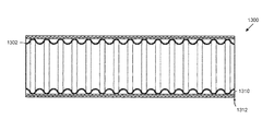
- FIG. 13 depicts a cross-section of an energy dissipative tube 1300 in accordance with preferred embodiments of the invention.
- the tube 1300 includes a length of corrugated stainless steel tubing 1302 , a conductive resin layer 1310 adjacent to the outside of the tubing, and an insulative resin layer 1312 adjacent to the conductive resin layer 1310 without a metallic layer interposed between the conductive resin layer 1310 and the insulative resin layer 1312 .
- corrugated stainless steel tubing and “CSST” refer to any type of tubing or piping, which may accommodate corrosive or aggressive gases or liquids, and includes but is not limited to tubing or piping made from: thermoplastics, metal or metal alloy materials such as olefin-based plastics (e.g., polyethylene (PE)), fluorocarbon polymers (e.g., polytetrafluoroethylene (PTFE)), carbon steel, copper, brass, aluminum, titanium, nickel, and alloys thereof.
- PE polyethylene
- PTFE polytetrafluoroethylene
- the term “resin” refers to any synthetic or naturally occurring polymer.
- Tubing having an energy dissipative jacket and methods for fabricating and installing the same are disclosed.
- the corrugated tubing 2 may be composed of stainless steel or any other suitable material.
- the tubing 2 contains a number of corrugation peaks 4 and corrugation valleys 6 .
- a jacket 8 (e.g., a multi-layer jacket) covers the outside of the tubing 2 .
- the jacket 8 can include a plurality of layers 10 , 12 .
- the layers 10 , 12 generally form an annulus around the tubing 2 , but may have a circular or non-circular cross-section.
- energy dissipative jackets 8 are provided that dissipate electrical and thermal energy throughout the respective jackets 8 , thereby protecting the tubing 2 .
- the term “dissipate” encompasses distributing electrical energy to an appropriate grounding device such as a fitting.
- Preferred embodiments of energy dissipative jackets preferably include one or more conductive layers for distributing electricity and heat.
- the conductive layers can include, for example, conductive resins and/or metals as discussed herein.
- the energy dissipative tubing 20 a includes a length of tubing 22 .
- the tubing 22 can be metal tubing, thin-walled metal tubing, corrugated tubing, corrugated stainless steel tubing, or the like.
- Tubing 22 is surrounded by a first resin layer 24 , a metal layer 26 a , and a second resin layer 28 .
- Resin layers 24 , 28 can be formed from insulative and/or conductive resins.
- Insulating resin layers can be formed from a variety of materials.
- an insulating elastic layer includes polytetrafluoroethylene (PTFE).
- PTFE polytetrafluoroethylene
- Other suitable insulators include polyolefin compounds, thermoplastic polymers, thermoset polymers, polymer compounds, polyethylene, crosslinked polyethylene, UV-resistant polyethylene, ethylene-propylene rubber, silicone rubber, polyvinyl chloride (PVC), ethylene tetrafluoroethylene (ETFE), and ethylene propylene diene monomer (EPDM) rubber.
- PVC polyvinyl chloride
- ETFE ethylene tetrafluoroethylene
- EPDM ethylene propylene diene monomer
- Conductive resin layers can be formed by impregnating a resin with conductive material such as metal particles (e.g., copper, aluminum, gold, silver, nickel, and the like), carbon black, carbon fibers, or other conductive additives.
- conductive material such as metal particles (e.g., copper, aluminum, gold, silver, nickel, and the like), carbon black, carbon fibers, or other conductive additives.
- the metal layer 26 and/or one or more of the resin layers 24 , 28 has a higher electrical conductivity than the tubing 22 .
- the volume resistivity of the conductive resin can be less than about 10 6 ohm-cm (e.g., 9 ⁇ 10 6 ohm-cm) as tested in accordance with ASTM standard D4496.
- each resin layer 24 , 28 has a thickness of about 0.015′′ to about 0.035′′.
- Metal layer 26 can include one or more metals (e.g., ductile metals) such as aluminum, cadmium, niobium (also known as “columbium”), copper, gold, nickel, platinum, silver, tantalum, titanium, zinc, zirconium, and the like and alloys thereof (e.g., austentitic nickel-chromium-based superalloys, brass, low carbon steel, phosphor bronze, stainless steel, and the like).
- the metal(s) can be formed into foils, perforated foils, tapes, perforated tapes, cables, wires, strands, meshes, braids, and the like.
- the metal layer 26 is an expanded metal foil.
- expanded metal foils are available from the Dexmet Corporation of Wallingford, Conn. Several exemplary embodiments of energy dissipative tubing 20 with various expanded metal foils are depicted in FIGS. 2A-2D .
- Expanded metal foils are particularly advantageous because they provide uniform protection while minimizing weight and allowing for flexibility of the tubing 20 .
- the expanded metal foil will either stretch or break on the outside of the bend. In either case, a continuous path is still maintained in the inside of the bend to allow for energy to be dissipated.
- the expanded metal foil can be designed to not break on the outside of a bend with an appropriate design based on specified bend radii.
- expanded or perforated metal foils include a plurality of voids.
- the voids can be formed in a variety of shapes including circles, ellipses, triangles, quadrilaterals, rectangles, squares, trapezoids, parallelograms, rhombuses, pentagons, hexagons, heptagons, octagons, nonagons, decagons, n-gons, and the like.
- the voids can be formed through a variety of techniques. For example, a plurality of foils or wires can be assembled in a parallel formation and bonded at regular intervals before the bonded assembly is stretched laterally to form voids between the non-bonded portions of the foils or wires.
- the voids can be created with a mechanical device (e.g., dies, drills, punches, molds, and the like), chemical means (e.g., chemical etching, photochemical etching, and the like), and/or electrical means (e.g., electrical discharge machining and the like).
- a mechanical device e.g., dies, drills, punches, molds, and the like
- chemical means e.g., chemical etching, photochemical etching, and the like
- electrical means e.g., electrical discharge machining and the like.
- the metal layer 26 completely surrounds the first resin layer 24 .
- the metal may overlap and/or be welded or soldered in some regions.
- the metal layer 26 substantially surrounds the first resin layer 24 .
- a small portion of the first resin layer 24 e.g., less than about 1°, less than about 2°, less than about 3°, less than about 4°, less than about 5°, less than about 10°, less than about 15°, less than about 20°, and the like
- the metal layer 26 can be wrapped spirally or helically around the first resin layer 24 . In such an embodiment, the metal layer 26 can overlap or substantially surround the first resin layer 24
- Various thicknesses of the resin layers 24 , 28 and the metal layer 26 can be selected to achieve desired resistance to lightning strikes and physical damage while maintaining desired levels of flexibility. In embodiments including an expanded metal foil, the mass per area can be adjusted to provide an appropriate amount of energy dissipation.
- the resin layers 24 , 28 can be the same or different thickness and can include the same or different materials. Various colors or markings can be added to resin layers, for example, to clearly distinguish the resin layers 24 , 28 from each other and from the metal layer 26 and/or to make the tubing 20 more conspicuous.
- the expanded metal foil 26 a has a plurality of rhombus-shaped voids (e.g., rhombuses with internal angles of approximately 80° and approximately 100°).
- the expanded metal foil 26 b again has a plurality of rhombus-shaped voids. Expanded metal foil 26 b differs from expanded metal foil 26 a by the lengthening of the voids 26 b .
- the voids can be rhombuses with internal angles of approximately 70° and approximately 110°.
- the expanded metal foil 26 c resembles to the expanded metal foil 26 b in FIG. 2B , but is wider relative to the voids.
- the expanded metal foil 26 d again has a plurality of rhombus-shaped voids.
- the expanded metal foil 26 d is wider between the voids and the rhombus-shaped voids approach square-shaped voids with internal angles of approximately 85° and approximately 95°.
- the metal layer 26 has a thickness between about 0.003′′ and about 0.010′′. This thickness can be varied to reflect varying properties of metals. In some embodiments, the metal layer 26 has a mass per square foot between about 0.045 and about 0.070 pounds per square foot.
- FIGS. 3A and 3B a variety of expanded metal foils are available.
- MICROGRID® expanded metal foils available from Dexmet Corporation, are specified by product codes illustrated by FIG. 3B in the context of FIG. 3A .
- the first number in the product code indicates the base material thickness in thousandths of inches.
- the letters indicate the chemical symbol of the material.
- the second numbers indicate the strand width in thousandths of inches.
- the third number indicates the length of the long axis of the void or diamond in thousandths of inches.
- the second letters indicate post-production processing of the expanded metal foil.
- the letter “F” indicates that the expanded metal foil is flattened.
- the letter “A” indicates that the expanded metal foil is annealed.
- a variety of expanded metal foils are suitable for use in embodiments of the invention including 3CU7-100FA, 8AL19-125F, 10AL14-190F, 3CU14-125FA, 6AL8-080F, and the like.
- the energy dissipative tubing 40 a includes a length of tubing 42 a surrounded by a metal layer 44 a and a resin layer 46 a .
- Metal layer 44 a and resin layer 46 a can include the same or similar materials described in the context of FIGS. 2A-2D herein.
- the energy dissipative tubing 40 b includes a length of tubing 42 b surrounded by a resin layer 46 b and a metal layer 44 b .
- Metal layer 44 b and resin layer 46 b can include the same or similar materials described in the context of FIGS. 2A-2D herein.
- one or more layers positioned adjacent to the tubing 2 , 22 , 42 , 52 are conductive. Research shows that conductive layers can better protect thin-walled tubing 2 , 22 , 42 , 52 by substantially evenly distributing electricity throughout the tubing 2 , 22 , 42 , 52 and/or by providing sacrificial means to transfer and dissipate the electrical energy.
- insulative layers resist electrical energy until the potential difference between the inner conductive tubing and another conductive element is large enough to create a dielectric breakdown of the insulative layer thereby allowing electrical energy to enter through the compromised insulative layer and on to the thin-walled tubing 2 , 22 , 42 , 52 at a single point and damaging the thin-walled tubing 2 , 22 , 42 , 52 .
- the entire jacket is conductive.
- tubing 22 can be surrounded by a first conductive resin layer 24 , a metallic layer 26 , and a second conductive layer 28 .
- both energy dissipative corrugated or smooth bore tubing can be used to transport gases, liquids, and slurries.
- the particular configuration of energy dissipative conduits 50 can vary in compliance with various regulations (e.g., the National Electrical Code as published by the National Fire Protection Association and promulgated by various municipalities).
- the internal tube 52 is corrugated tubing as depicted in FIGS. 2A-2D .
- the internal tube 52 is a smooth bore tube as depicted in FIG. 5 .
- Tube 52 can be conventional conduit such as rigid metal conduit (RMC), rigid nonmetallic conduit (RNC), galvanized rigid conduit (GRC), electrical metallic tubing (EMT), electrical nonmetallic tubing (ENT), flexible metallic conduit (FMC), liquidtight flexible metal conduit (LFMC), flexible metallic tubing (FMT), liquidtight flexible nonmetallic conduit (LFNC), aluminum conduit, intermediate metal conduit (IMC), PVC conduit, and the like.
- RMC rigid metal conduit
- RMC rigid nonmetallic conduit
- GRC galvanized rigid conduit
- EMT electrical metallic tubing
- ENT electrical nonmetallic tubing
- FMC flexible metallic conduit
- LFMC liquidtight flexible metal conduit
- FMT flexible metallic tubing
- LFNC liquidtight flexible nonmetallic conduit
- IMC intermediate metal conduit
- PVC conduit and the like.
- an internal tube 52 is omitted.
- inner tube 52 can be enclosed in one or more resin layers 54 , 58 and one or more metal layers 56 .
- one or more layers of the jacket possess various properties such as flame resistance, heat resistance, sound insulation, temperature insulation, oil or water impermeability, and/or wear resistance.
- a layer may incorporate a fire retardant.
- Suitable layers include polymers incorporating about 20% to 60% magnesium hydroxide, aluminum trihydrate, and/or halogenated fire retardants by weight.
- one or more of the resin layers have a 25/50 flame spread/smoke density index as measured in accordance with the ASTM E84 standard.
- resin layers are capable of elongation greater than or equal to about 200% as measured in accordance with the ASTM D638 standard.
- the outer layer includes wear resistant materials such as wire, cable, strands of material such as poly-aramid synthetic fiber such as KEVLAR® (available from E.I. Du Pont de Nemours and Company of Wilmington, Del.), and the like. Such materials may be incorporated within a polymer or resin layer or may be exposed.
- a layer is formed by twisting an interlocking metal strip around the tubing and underlying jacket layers similar to the metal sheath on BX or TECK type electrical cables.
- Energy dissipative tubing can be fabricated in accordance with existing techniques for the manufacture of CSST.
- An exemplary method 60 for fabricating energy dissipative tubing is depicted in FIG. 6 .
- a length of tubing is provided.
- the tubing can be metal tubing, thin-walled metal tubing, corrugated tubing, corrugated stainless steel tubing, and the like. Embodiments of suitable tubing are described herein.
- a resin layer is applied to the exterior of the tubing (and any intervening jacket layers).
- the resin layer can be applied by known extrusion techniques.
- a metal layer is applied to the exterior of the tubing (and any intervening jacket layers).
- the metal layer can be applied by a variety of techniques. Foils, tapes, wires, and the like can be wound onto the tubing.
- an adhesive e.g., an electrically conductive adhesive
- Braids and meshes can be formed by various known techniques in the rope-, wire-, and cable-making fields.
- steps S 64 and S 66 can be repeated in variety of patterns.
- consecutive resin and/or metal layers can be applied to the tubing.
- the metal layer is embedded or partially embedded in one or both of the resin layers. This can be accomplished by pressing the metal layer into the resin layer while the resin is curing. In other embodiments, the metal is applied over a cured resin layer (e.g., to aid in easy removal of the metal layer for installation and/or recycling).
- Energy dissipative tubing can be installed in accordance with existing techniques for the manufacture of CSST.
- An exemplary method 70 for installing energy dissipative tubing is depicted in FIG. 7 .
- a length of energy dissipative tubing is provided.
- Tubing may be provided in lengths (e.g., 8′ sticks) or on reels.
- one or more jacket layers are optionally removed in accordance with the instructions for a fitting.
- the one or more layers can be removed with existing tools such as a utility knife, a razor blade, a tubing cutter, and the like.
- the fitting is coupled to the tubing in accordance with the instructions for the fitting.
- the fitting may, in some embodiments, contact one or more conductive layers (e.g., conductive resin layers or metal layers) to create electrical continuity between the conductive layer(s) and the fitting, thereby grounding the conductive layer(s).
- the fitting can include one or more conductive teeth that penetrate an outer resin layer to ground the metal layer.
- a schematic of the testing apparatus 80 is provided in FIG. 8 .
- a length of tubing 82 (including any metallic layers) is connected to power source 84 .
- Tubing 82 can be any tubing or conduit described herein or can be other tubing for use as a control during testing.
- the power source 84 can, in some embodiments, contain three energy storage capacitors/battery banks that are capable of producing the waveforms described as current components A/D, B, and C in SAE Standard No. ARP5412 discussed above.
- Ground plate 86 contacts or is in close proximity to tubing 82 at contact point 88 .
- capacitors/battery banks A/D, B, C are discharged at the same time. The electricity arcs through any resin layers at contact point 88 and flows to ground plate 86 .
- samples A and C lengths of tubing (Samples A and C) including a layer of 8AL19-125F MICROGRID® expanded metal foil, available from Dexmet Corporation, and a length of conventional tubing (Sample B) coated with a conductive resin were exposed to A/D, B, C electrical current waveforms in accordance with SAE ARP5412.
- FIGS. 9A and 9B clearly demonstrate the effectiveness of the energy dissipating layers described herein.
- FIG. 9A depicts Sample A.
- FIG. 9A ( 1 ) a portion of the outer resin layer is ablated. Further removal of the outer resin layer in FIG. 9A ( 2 ) clearly shows the vaporization of a portion of the energy dissipating layer, protecting the inner resin layer and the corrugated tubing.
- FIG. 9A ( 3 ) shows the extent of vaporization.
- FIG. 9A ( 4 ) a portion of the inner resin layer is removed to demonstrate that although the corrugated tubing is slightly deformed, the corrugated tubing is still intact.
- FIG. 9B depicts Sample B, which catastrophically failed and was completely separated into two pieces.
- the sealing device 1000 can include a body (or adapter) 1004 including a sleeve portion 1006 .
- the energy dissipative tubing 1002 can be any tubing configured to dissipate electrical energy. Various examples of energy dissipative tubing 1002 are described herein. In one example depicted in FIG. 10 , the energy dissipative tubing 1002 includes a length of tubing 1008 (e.g., corrugated stainless steel tubing), a first resin layer 1010 adjacent to the tubing 1008 , a conductive layer 1012 adjacent to the first resin layer 1010 , and a second resin layer 1014 adjacent to the conductive layer 1012 .
- tubing 1008 e.g., corrugated stainless steel tubing
- the sealing device 1000 includes one or more penetrating members 1016 configured to penetrate the second (or exterior) resin layer 1014 and establish electrical continuity with the conductive layer 1012 .
- penetrate encompasses situations in which the penetrating member 1016 does not completely pierce the second resin layer 1014 , but does penetrate the second resin layer 1014 sufficiently so that electrical continuity is established across the partially-penetrated second resin layer 1014 .
- Penetrating members 1016 can be arranged in a variety of configurations.
- the penetrating members 1016 can be one or more teeth.
- the penetrating members can be a protrusion arranged on a split bushing 1018 .
- the penetrating members 1016 disclosed in the embodiment of FIG. 10 provide a plurality of cutting surfaces as further described in the context of FIGS. 11A and 11B .
- FIG. 11A depicts an exploded view of a split bushing 1100 around tubing 1102 .
- the split bushing 1100 includes one or more components 1104 (e.g., two 180° sectors).
- One or more of the bushing components 1104 can include a penetrating member 1106 configured to penetrate one or more layers of the energy dissipative tubing 1102 .
- components 1104 a and 1104 b include circumferential penetrating members 1106 a and 1106 b , respectively.
- the penetrating members 1106 a , 1106 b extend continuously around the inner surface of the components 1104 a , 1104 b , the penetrating members 1106 can, in other embodiments, be discontinuous.
- one or more penetrating members e.g., teeth or the like
- the split bushing 1018 , 1100 described herein is particularly advantageous because it is arranged to penetrate one or more layers of the energy dissipative tubing in two directions, thereby providing more robust and predictable electrical continuity with the conductive layer 1012 .
- split bushing components 1104 a , 1104 b are compressed (i.e., pushed together)
- the penetrating member 1106 presses radially against the second resin layer 1014 to substantially uniformly penetrate the second resin layer 1014 .
- the ends 1108 of the penetrating members 1106 cut substantially tangentially across the second resin layer to establish further electrical continuity with the conductive layer 1012 .
- the tangential cutting path is illustrated by dashed lines in FIG. 11A .
- the split bushing 1018 , 1100 and the penetrating members 1106 can be configured to penetrate certain layers of energy dissipative tubing 1002 and can be further optimized to reflect the specific thicknesses and materials of various embodiments of energy dissipative tubing 1002 and to withstand certain levels of electrical and/or thermal energy.
- the penetrating members 1106 can be configured to penetrate only the second (or exterior) resin layer 1014 . In other embodiments, the penetrating members 1106 can penetrate the second (or exterior) resin layer 1014 , and partially or fully penetrate the conductive layer 1012 in order to establish better electrical continuity.
- the penetrating member 1106 can penetrate all layers of the energy dissipative tubing 1002 including the first (or inner) resin layer 1010 , and is in contact or in proximity to the tubing 1008 to form electrical continuity with the tubing 1008 in addition to conductive layer 1012 .
- electrical continuity can be established with the tubing 1008 through a metallic sealing face 1028 .
- the penetrating members 1016 , 1106 can be beveled and/or sharpened to better penetrate the desired layers 1010 , 1012 , 1014 .
- the penetrating members 1016 , 1106 can be triangular-shaped protrusions as depicted in FIGS. 10-11B .
- the split bushing 1018 and the sleeve portion 1006 can be configured to compress the split bushing 1018 as the split bushing is advanced towards a proximal end 1020 of the sealing device 1000 .
- the split bushing 1018 can include an enlarged diameter region 1022 , 1110 configured to interact with a tapered interior of sleeve portion 1006 to provide substantially uniform compression of split bushing 1018 as the split bushing is advanced proximally.
- the split bushing 1018 can be advanced proximally through a variety of techniques and components.
- the split bushing 1018 can be engaged by a tool and advanced proximally until the split bushing 1018 is held within the sleeve portion 1006 by friction, locking members, and/or retention members as described in International Publication No. WO 2008/150449.
- an exterior of the sleeve portion 1006 can be threaded in order to mate with a nut 1024 . As the nut 1024 is tightened, the split bushing 1018 is advanced proximally to compress the split bushing 1018 .
- the split bushing 1018 also forms a seal between the tubing 1008 and the sealing device 1000 .
- a seal can be a metal-to-metal seal formed by collapsing and compressing a first corrugation 1026 against a sealing face 1028 .
- the principles and various embodiments of such sealing devices are described in publications such as International Publication Nos. WO 2008/150449 and WO 2008/150469, which are incorporated by reference herein.
- split bushing 1018 can also be applied to various other mechanical devices such as multi-segment bushings, collets, split rings, and the like.
- a proximal end 1020 can be configured for coupling with various fittings, pipes (e.g., black iron pipe), appliances and the like.
- the proximal end 1020 can include male or female threads, for example in accordance with the American National Standard Taper Pipe Thread (NPT) standard, which is discussed, for example, at Erik Oberg et al., Machinery's Handbook 1861-65 (28th ed. 2008).
- NPT American National Standard Taper Pipe Thread
- the proximal end is sized for a sweat/solder connection or a compression connection.
- the sealing device is configured to couple two lengths of the energy dissipative tubing 1002 having the sleeve portions 1006 on both ends for receiving the split bushings 1006 and the energy dissipative tubing 1002 .
- the sealing device 1000 , split bushing 1018 , and/or nut 1024 can be fabricated from materials such as metals (e.g., iron, copper, aluminum, gold, silver, and the like), metal alloys (e.g., brass, bronze, steel, and the like), plastics, polymers, elastomers, and the like.
- metals e.g., iron, copper, aluminum, gold, silver, and the like
- metal alloys e.g., brass, bronze, steel, and the like
- plastics e.g., polymers, elastomers, and the like.
- the sealing device 1000 , split bushing 1018 , and/or nut 1024 are fabricated from conductive materials in order to provide a conductive path between the energy dissipative tubing 1002 to a grounding conductor (e.g., a fitting, a pipe, an appliance, a grounding wire, and the like).
- grounding conductor e.g., a fitting, a pipe
- the sealing devices described herein can be attached in the field or in a factory.
- a method 1200 of installing energy dissipative tubing is provided.
- a length of energy dissipative tubing is provided.
- the energy dissipative tubing can be the same or similar to the energy dissipative tubing described herein.
- the energy dissipative tubing can include a length of tubing (e.g., corrugated stainless steel tubing), a first resin layer adjacent to the tubing, a conductive layer adjacent to the first resin layer, and a second resin layer adjacent to the conductive layer.
- a sealing device is coupled to the end of the energy dissipative tubing.
- the sealing device can include one or more penetrating members configured to penetrate the second resin layer and establish electrical continuity with the conductive layer.
- the coupling step S 1204 can include a variety of sub-steps.
- one or more jacket layers can be removed (e.g., with a utility knife, a razor blade, a tubing cutter, and the like) to expose one or more corrugations.
- a split bushing can be placed over the energy dissipative tubing.
- the split bushing can be provided within a sleeve portion of the sealing device and removed by the installer or can be provided outside of the sealing device.
- the assembled tubing and split bushing can then be inserted into a sleeve portion of the sealing device in step S 1208 b.
- step S 1208 c the energy dissipative tubing is inserted into the split bushing without removing the split bushing from the sealing device.
- step S 1210 the split bushing is compressed.
- the split bushing can be compressed as it is proximally advanced within the sleeve portion as discussed herein. As further discussed herein, the split bushing can be advanced through the use of a tool or by tightening of a nut.
Abstract
One aspect of the invention provides an energy dissipative tube including: a length of corrugated stainless steel tubing; a conductive resin layer adjacent to the outside of the tubing; and an insulative resin layer adjacent to the conductive layer. Another aspect of the invention provides an energy dissipative tube consisting of: a length of corrugated stainless steel tubing; a conductive thermoplastic polymer layer adjacent to the outside of the tubing, the conductive thermoplastic polymer layer having a volume resistivity of less than about 106 ohm-cm; and an insulative resin layer adjacent to the conductive layer.
Description
This is a continuation under 35 U.S.C. §120 of U.S. patent application Ser. No. 12/828,769, filed Jul. 1, 2010, which claims priority to under 35 U.S.C. §119(e) to U.S. Provisional Patent Application Ser. No. 61/235,910, filed on Aug. 21, 2009, and U.S. Provisional Patent Application Ser. No. 61/321,689, filed on Apr. 7, 2010. The entire contents of each application is hereby incorporated by reference herein.
The present invention relates to gas, liquid, and slurry piping systems as well as protective conduit systems for cable carrying purposes, and more particularly to piping or tubing systems incorporating jackets and fittings capable of transferring and dissipating energy.
Gas and liquid piping systems utilizing corrugated stainless steel tubing (“CSST”) and fittings are known. Such piping systems can be designed for use in combination with elevated pressures of up to about 25 psi or more and provide advantages over traditional rigid black iron piping systems in terms of ease and speed of installation, elimination of onsite measuring, and reduction in the need for certain fittings such as elbows, tees, and couplings.
Oftentimes, electrical currents will occur inside a structure. These electrical currents, which can vary in duration and magnitude, can be the result of power fault currents or induced currents resulting from lightning interactions with a house or structure. The term “fault current” is typically used to describe an overload in an electrical system, but is used broadly herein to include any electrical current that is not normal in a specific system. These currents can be the result of any number of situations or events such as a lightning event. Electrical currents from lightning can reach a structure directly or indirectly. Direct currents result from lightning that attaches to the actual structure or a system contained within the structure. When current from a nearby lightning stroke moves through the ground or other conductors into a structure, it is referred to as indirect current. While both direct and indirect currents may enter a structure through a particular system, voltage can be induced in other systems in the structure, especially those in close proximity to piping systems. This can often result in an electrical flashover or arc between the adjacent systems. A flashover occurs when a large voltage differential exists between two electrical conductors and the air ionizes and the material between the conductive bodies are punctured by the high voltage and form a spark.
Energy dissipative tubes, sealing devices, and methods of fabricating and installing the same are provided.
One aspect of the invention provides an energy dissipative tube including: a length of tubing; a first resin layer surrounding the outside of the tubing; an expanded metal foil adjacent to the outside of the first resin layer; and a second resin layer surrounding the expanded metal foil and the first resin layer.
This aspect can have a variety of embodiments. The first resin layer can include one or more materials selected from the group consisting of: a polymer, a thermoplastic polymer, and a thermoset polymer. The second resin layer can include one or more materials selected from the group consisting of: a polymer, a thermoplastic polymer, and a thermoset polymer.
The first resin layer can be electrically conductive. The first resin layer can have a volume resistivity of less than about 106 ohm-cm. The first resin layer can be electrically insulative. The second resin layer can be electrically conductive. The second resin layer can have a volume resistivity of less than about 106 ohm-cm. The second resin layer can be electrically insulative.
The expanded metal foil can completely surround the first resin layer. The expanded metal foil can substantially surround the first resin layer.
The tubing can be metallic tubing. The tubing can be thin-walled tubing. The tubing can be flexible tubing. The tubing can be corrugated tubing.
Another aspect of the invention provides an energy dissipative tube including: a length of tubing; a conductive layer adjacent to the outside of the tubing; and an insulative layer adjacent to the conductive layer.
This aspect can have a variety of embodiments. The conductive layer can include a metal. The metal can be a foil. The metal can be an expanded foil. The metal can be a perforated foil. The metal can be a metal tape. The metal can be a perforated metal tape. The metal can include one or more wires. The wires can be formed into a mesh. The one or more wires can be braided. The metal can include one or more selected from the group consisting of: copper, aluminum, silver, and gold. The conductive layer can have a higher electrical conductivity than the tubing. The tubing can be corrugated tubing.
The conductive layer can be a conductive resin. The conductive resin can have a volume resistivity of less than about 106 ohm-cm.
Another aspect of the invention provides an energy dissipative tube including: a length of tubing; a metal layer adjacent to the outside of the tubing; and a resin layer adjacent to the metal layer.
This aspect can have a variety of embodiments. The metal layer can be an expanded foil. The resin can be a conductive resin. The conductive resin can have a volume resistivity of less than about 106 ohm-cm. The resin can be an insulative resin.
Another aspect of the invention provides an energy dissipative tube including: a length of tubing; a resin layer adjacent to the outside of the tubing; and a metal layer adjacent to the resin layer.
Another aspect of the invention provides a method of fabricating energy dissipative tubing. The method includes: providing a length of tubing; applying a first resin layer surrounding the outside of the tubing; applying an expanded metal foil adjacent to the outside of the first resin layer; and applying a second resin layer surrounding the expanded metal foil and the first resin layer.
Another aspect of the invention provides a method of fabricating energy dissipative tubing. The method includes: providing a length of tubing; applying a conductive layer adjacent to the outside of the tubing; and applying an insulative layer adjacent to the conductive layer.
Another aspect of the invention provides a method of installing energy dissipative tubing. The method includes: providing a length of energy dissipative tubing including a length of tubing, a first resin layer surrounding the outside of the tubing, an expanded metal foil adjacent to the outside of the first resin layer, and a second resin layer surrounding the expanded metal foil and the first resin layer; and coupling a fitting to an end of the energy dissipative tubing. The fitting creates electrical continuity with the expanded metal foil.
Another aspect of the invention provides a method of installing energy dissipative tubing. The method includes: providing a length of energy dissipative tubing including a length of tubing, a conductive layer adjacent to the outside of the tubing, and an insulative layer adjacent to the conductive layer; and coupling a fitting to an end of the energy dissipative tubing. The fitting creates electrical continuity with the conductive layer.
Another aspect of the invention provides a sealing device for connecting an energy dissipative tube having a length of tubing, a first resin layer surrounding the outside of the tubing, a conductive layer adjacent to the outside of the first resin layer, and a second resin layer surrounding the conductive layer and the first resin layer. The sealing device includes one or more penetrating members configured to penetrate the second resin layer and establish electrical continuity with the conductive layer.
This aspect can have a variety of embodiments. In one embodiment, the one or more penetrating members do not penetrate the first resin layer. In another embodiment, the one or more penetrating members do not establish electrical continuity with the tubing. In still another embodiment, the one or more penetrating members are substantially triangular. In yet another embodiment, the one or more penetrating members are formed on a split bushing.
The one or more penetrating members can extend circumferentially around the split bushing. The one or more penetrating members can include at least one radial cutting edge. The one or more penetrating members can include at least one tangential cutting edge.
The sealing device of claim can include a sleeve portion. The split bushing can be received within the sleeve portion. The exterior of the sleeve portion can include one or more threads. The sealing device can include a nut operably connected to the one or more threads on the exterior of the sleeve portion. The nut can be configured to advance the bushing when the nut is tightened. The split bushing can have a geometry that interacts with the sleeve portion to facilitate penetrating the second resin layer and establishing electrical continuity with the conductive layer.
The split bushing can be metallic. The split bushing can be brass. The one or more penetrating members can be metallic. The sealing device can be configured to form a seal with one end of the length of tubing and wherein electrical continuity is established between the sealing device and the end of the length of tubing.
Another aspect of the invention provides a sealing device for connecting an energy dissipative tube having a length of tubing, a first resin layer surrounding the outside of the tubing, a conductive layer adjacent to the outside of the first resin layer, and a second resin layer surrounding the conductive layer and the first resin layer. The sealing device includes: a body member including a sleeve portion and a bushing arranged to be received in the sleeve portion. The bushing includes one or more penetrating members configured to penetrate the second resin layer and establish electrical continuity with the conductive layer.
This aspect can have a variety of embodiments. The bushing can be a split bushing. The split bushing can be configured to penetrate the second resin layer substantially radially. The split bushing can be configured to penetrate the second resin layer substantially tangentially.
The exterior of the sleeve portion can include one or more threads. The sealing device can include a nut operably connected to the one or more threads on the exterior of the sleeve portion. The nut is arranged to advance the bushing when the nut is tightened.
Another aspect of the invention provides a method of installing energy dissipative tubing. The method includes: providing a length of energy dissipative tubing including a length of tubing, a first resin layer surrounding the outside of the tubing, an expanded metal foil adjacent to the outside of the first resin layer, and a second resin layer surrounding the expanded metal foil and the first resin layer; and coupling a sealing device to an end of the energy dissipative tubing. The sealing device includes one or more penetrating members configured to penetrate the second resin layer and establish electrical continuity with the expanded metal foil.
This aspect can have a variety of embodiments. In one embodiment, the one or more penetrating members are arranged on a split bushing.
For a fuller understanding of the nature and desired objects of the present invention, reference is made to the following detailed description taken in conjunction with the accompanying drawing figures wherein like reference characters denote corresponding parts throughout the several views and wherein:
The instant invention is most clearly understood with reference to the following definitions:
As used herein, the singular form “a”, “an” and “the” include plural references unless the context clearly dictates otherwise.
As used herein, the terms “corrugated stainless steel tubing” and “CSST” refer to any type of tubing or piping, which may accommodate corrosive or aggressive gases or liquids, and includes but is not limited to tubing or piping made from: thermoplastics, metal or metal alloy materials such as olefin-based plastics (e.g., polyethylene (PE)), fluorocarbon polymers (e.g., polytetrafluoroethylene (PTFE)), carbon steel, copper, brass, aluminum, titanium, nickel, and alloys thereof.
As used herein, the term “resin” refers to any synthetic or naturally occurring polymer.
Tubing having an energy dissipative jacket and methods for fabricating and installing the same are disclosed.
Referring to FIG. 1 , a length of corrugated tubing 2 according to the prior art is provided. The corrugated tubing 2 may be composed of stainless steel or any other suitable material. The tubing 2 contains a number of corrugation peaks 4 and corrugation valleys 6. A jacket 8 (e.g., a multi-layer jacket) covers the outside of the tubing 2.
The jacket 8 can include a plurality of layers 10, 12. The layers 10, 12 generally form an annulus around the tubing 2, but may have a circular or non-circular cross-section.
Energy Dissipative Tubing
In order to better absorb energy from fault currents and lightning strikes, according to preferred embodiments of the invention, energy dissipative jackets 8 are provided that dissipate electrical and thermal energy throughout the respective jackets 8, thereby protecting the tubing 2. The term “dissipate” encompasses distributing electrical energy to an appropriate grounding device such as a fitting.
Preferred embodiments of energy dissipative jackets preferably include one or more conductive layers for distributing electricity and heat. The conductive layers can include, for example, conductive resins and/or metals as discussed herein.
Referring now to FIG. 2A , one embodiment of energy dissipative tubing 20 a is provided. The energy dissipative tubing 20 a includes a length of tubing 22. The tubing 22 can be metal tubing, thin-walled metal tubing, corrugated tubing, corrugated stainless steel tubing, or the like.
Insulating resin layers can be formed from a variety of materials. In some embodiments, an insulating elastic layer includes polytetrafluoroethylene (PTFE). Other suitable insulators include polyolefin compounds, thermoplastic polymers, thermoset polymers, polymer compounds, polyethylene, crosslinked polyethylene, UV-resistant polyethylene, ethylene-propylene rubber, silicone rubber, polyvinyl chloride (PVC), ethylene tetrafluoroethylene (ETFE), and ethylene propylene diene monomer (EPDM) rubber.
Conductive resin layers can be formed by impregnating a resin with conductive material such as metal particles (e.g., copper, aluminum, gold, silver, nickel, and the like), carbon black, carbon fibers, or other conductive additives. In some embodiments, the metal layer 26 and/or one or more of the resin layers 24, 28 has a higher electrical conductivity than the tubing 22. In some embodiments, the volume resistivity of the conductive resin can be less than about 106 ohm-cm (e.g., 9×10⁶ ohm-cm) as tested in accordance with ASTM standard D4496.
In some embodiments, each resin layer 24, 28 has a thickness of about 0.015″ to about 0.035″.
Metal layer 26 can include one or more metals (e.g., ductile metals) such as aluminum, cadmium, niobium (also known as “columbium”), copper, gold, nickel, platinum, silver, tantalum, titanium, zinc, zirconium, and the like and alloys thereof (e.g., austentitic nickel-chromium-based superalloys, brass, low carbon steel, phosphor bronze, stainless steel, and the like). The metal(s) can be formed into foils, perforated foils, tapes, perforated tapes, cables, wires, strands, meshes, braids, and the like.
In some embodiments, the metal layer 26 is an expanded metal foil. A variety of expanded metal foils are available from the Dexmet Corporation of Wallingford, Conn. Several exemplary embodiments of energy dissipative tubing 20 with various expanded metal foils are depicted in FIGS. 2A-2D .
Expanded metal foils are particularly advantageous because they provide uniform protection while minimizing weight and allowing for flexibility of the tubing 20. When the tubing 20 is bent, the expanded metal foil will either stretch or break on the outside of the bend. In either case, a continuous path is still maintained in the inside of the bend to allow for energy to be dissipated. The expanded metal foil can be designed to not break on the outside of a bend with an appropriate design based on specified bend radii.
In some embodiments, expanded or perforated metal foils include a plurality of voids. The voids can be formed in a variety of shapes including circles, ellipses, triangles, quadrilaterals, rectangles, squares, trapezoids, parallelograms, rhombuses, pentagons, hexagons, heptagons, octagons, nonagons, decagons, n-gons, and the like. The voids can be formed through a variety of techniques. For example, a plurality of foils or wires can be assembled in a parallel formation and bonded at regular intervals before the bonded assembly is stretched laterally to form voids between the non-bonded portions of the foils or wires. Additionally or alternatively, the voids can be created with a mechanical device (e.g., dies, drills, punches, molds, and the like), chemical means (e.g., chemical etching, photochemical etching, and the like), and/or electrical means (e.g., electrical discharge machining and the like).
In some embodiments, the metal layer 26 completely surrounds the first resin layer 24. In such embodiments, the metal may overlap and/or be welded or soldered in some regions. In other embodiments, the metal layer 26 substantially surrounds the first resin layer 24. In such embodiments, a small portion of the first resin layer 24 (e.g., less than about 1°, less than about 2°, less than about 3°, less than about 4°, less than about 5°, less than about 10°, less than about 15°, less than about 20°, and the like) is not surrounded by the metal layer 26. In still other embodiments, the metal layer 26 can be wrapped spirally or helically around the first resin layer 24. In such an embodiment, the metal layer 26 can overlap or substantially surround the first resin layer 24
Various thicknesses of the resin layers 24, 28 and the metal layer 26 can be selected to achieve desired resistance to lightning strikes and physical damage while maintaining desired levels of flexibility. In embodiments including an expanded metal foil, the mass per area can be adjusted to provide an appropriate amount of energy dissipation. The resin layers 24, 28 can be the same or different thickness and can include the same or different materials. Various colors or markings can be added to resin layers, for example, to clearly distinguish the resin layers 24, 28 from each other and from the metal layer 26 and/or to make the tubing 20 more conspicuous.
Referring again to FIGS. 2A-2D , various embodiments of tubing 20 having expanded metal foils are provided. In FIG. 2A , the expanded metal foil 26 a has a plurality of rhombus-shaped voids (e.g., rhombuses with internal angles of approximately 80° and approximately 100°). In FIG. 2B , the expanded metal foil 26 b again has a plurality of rhombus-shaped voids. Expanded metal foil 26 b differs from expanded metal foil 26 a by the lengthening of the voids 26 b. For example the voids can be rhombuses with internal angles of approximately 70° and approximately 110°. In FIG. 2C , the expanded metal foil 26 c resembles to the expanded metal foil 26 b in FIG. 2B , but is wider relative to the voids. In FIG. 2D , the expanded metal foil 26 d again has a plurality of rhombus-shaped voids. The expanded metal foil 26 d is wider between the voids and the rhombus-shaped voids approach square-shaped voids with internal angles of approximately 85° and approximately 95°.
In some embodiments, the metal layer 26 has a thickness between about 0.003″ and about 0.010″. This thickness can be varied to reflect varying properties of metals. In some embodiments, the metal layer 26 has a mass per square foot between about 0.045 and about 0.070 pounds per square foot.
Referring now to FIGS. 3A and 3B , a variety of expanded metal foils are available. For example, MICROGRID® expanded metal foils, available from Dexmet Corporation, are specified by product codes illustrated by FIG. 3B in the context of FIG. 3A . The first number in the product code indicates the base material thickness in thousandths of inches. The letters indicate the chemical symbol of the material. The second numbers indicate the strand width in thousandths of inches. The third number indicates the length of the long axis of the void or diamond in thousandths of inches. The second letters indicate post-production processing of the expanded metal foil. The letter “F” indicates that the expanded metal foil is flattened. The letter “A” indicates that the expanded metal foil is annealed. A variety of expanded metal foils are suitable for use in embodiments of the invention including 3CU7-100FA, 8AL19-125F, 10AL14-190F, 3CU14-125FA, 6AL8-080F, and the like.
Referring now to FIG. 4A , an alternate preferred embodiment of energy dissipative tubing 40 a is provided. The energy dissipative tubing 40 a includes a length of tubing 42 a surrounded by a metal layer 44 a and a resin layer 46 a. Metal layer 44 a and resin layer 46 a can include the same or similar materials described in the context of FIGS. 2A-2D herein.
Referring now to FIG. 4B , an alternate preferred embodiment of energy dissipative tubing 40 b is provided. The energy dissipative tubing 40 b includes a length of tubing 42 b surrounded by a resin layer 46 b and a metal layer 44 b. Metal layer 44 b and resin layer 46 b can include the same or similar materials described in the context of FIGS. 2A-2D herein.
In some embodiments, one or more layers positioned adjacent to the tubing 2, 22, 42, 52 are conductive. Research shows that conductive layers can better protect thin- walled tubing 2, 22, 42, 52 by substantially evenly distributing electricity throughout the tubing 2, 22, 42, 52 and/or by providing sacrificial means to transfer and dissipate the electrical energy. In contrast, insulative layers resist electrical energy until the potential difference between the inner conductive tubing and another conductive element is large enough to create a dielectric breakdown of the insulative layer thereby allowing electrical energy to enter through the compromised insulative layer and on to the thin- walled tubing 2, 22, 42, 52 at a single point and damaging the thin- walled tubing 2, 22, 42, 52.
In some embodiments, the entire jacket is conductive. For example, tubing 22 can be surrounded by a first conductive resin layer 24, a metallic layer 26, and a second conductive layer 28.
Energy Dissipative Conduits
The principles discussed herein can be used in applications other than the transportation of fluids. For example, the principles and embodiments described herein can be applied to produce energy dissipative corrugated or smooth bore conduits for the protection and routing of electrical and communication cables (e.g., coaxial cable, twisted pair cable, fiber optic cable, and the like). Likewise, both energy dissipative corrugated or smooth bore tubing can be used to transport gases, liquids, and slurries.
Referring now to FIG. 5 , the particular configuration of energy dissipative conduits 50 can vary in compliance with various regulations (e.g., the National Electrical Code as published by the National Fire Protection Association and promulgated by various municipalities). In some embodiments, the internal tube 52 is corrugated tubing as depicted in FIGS. 2A-2D . In still other embodiments, the internal tube 52 is a smooth bore tube as depicted in FIG. 5 . Tube 52 can be conventional conduit such as rigid metal conduit (RMC), rigid nonmetallic conduit (RNC), galvanized rigid conduit (GRC), electrical metallic tubing (EMT), electrical nonmetallic tubing (ENT), flexible metallic conduit (FMC), liquidtight flexible metal conduit (LFMC), flexible metallic tubing (FMT), liquidtight flexible nonmetallic conduit (LFNC), aluminum conduit, intermediate metal conduit (IMC), PVC conduit, and the like. In some embodiments, an internal tube 52 is omitted.
As described herein, inner tube 52 can be enclosed in one or more resin layers 54, 58 and one or more metal layers 56.
Additional Layer Features
In further embodiments of the invention, one or more layers of the jacket possess various properties such as flame resistance, heat resistance, sound insulation, temperature insulation, oil or water impermeability, and/or wear resistance.
For example, a layer (e.g., the outermost layer) may incorporate a fire retardant. Suitable layers include polymers incorporating about 20% to 60% magnesium hydroxide, aluminum trihydrate, and/or halogenated fire retardants by weight.
In some embodiments, one or more of the resin layers have a 25/50 flame spread/smoke density index as measured in accordance with the ASTM E84 standard.
In order to better comply with installation requirements, some embodiments of resin layers are capable of elongation greater than or equal to about 200% as measured in accordance with the ASTM D638 standard.
In other embodiments, the outer layer includes wear resistant materials such as wire, cable, strands of material such as poly-aramid synthetic fiber such as KEVLAR® (available from E.I. Du Pont de Nemours and Company of Wilmington, Del.), and the like. Such materials may be incorporated within a polymer or resin layer or may be exposed. In some embodiments, a layer is formed by twisting an interlocking metal strip around the tubing and underlying jacket layers similar to the metal sheath on BX or TECK type electrical cables.
Although embodiments of the invention having two or three layer jackets are depicted and discussed herein, the invention is not limited to jackets having particular number of layers. Rather, additional embodiments in which a jacket includes more than three layers are contemplated according to the principles, patterns, and spirit of the specific embodiments described herein.
Methods of Fabricating Energy Dissipative Tubing
Energy dissipative tubing can be fabricated in accordance with existing techniques for the manufacture of CSST. An exemplary method 60 for fabricating energy dissipative tubing is depicted in FIG. 6 .
In step S62, a length of tubing is provided. The tubing can be metal tubing, thin-walled metal tubing, corrugated tubing, corrugated stainless steel tubing, and the like. Embodiments of suitable tubing are described herein.
In step S64, a resin layer is applied to the exterior of the tubing (and any intervening jacket layers). The resin layer can be applied by known extrusion techniques.
In step S66, a metal layer is applied to the exterior of the tubing (and any intervening jacket layers). The metal layer can be applied by a variety of techniques. Foils, tapes, wires, and the like can be wound onto the tubing. In some embodiments, an adhesive (e.g., an electrically conductive adhesive) is used to secure the metal layer to the tubing and/or an intervening jacket layer. Braids and meshes can be formed by various known techniques in the rope-, wire-, and cable-making fields.
As will be appreciated, steps S64 and S66 can be repeated in variety of patterns. For example, consecutive resin and/or metal layers can be applied to the tubing.
In some embodiments, the metal layer is embedded or partially embedded in one or both of the resin layers. This can be accomplished by pressing the metal layer into the resin layer while the resin is curing. In other embodiments, the metal is applied over a cured resin layer (e.g., to aid in easy removal of the metal layer for installation and/or recycling).
Methods of Installing Energy Dissipative Tubing
Energy dissipative tubing can be installed in accordance with existing techniques for the manufacture of CSST. An exemplary method 70 for installing energy dissipative tubing is depicted in FIG. 7 .
In step S72, a length of energy dissipative tubing is provided. Tubing may be provided in lengths (e.g., 8′ sticks) or on reels.
In step S74, one or more jacket layers are optionally removed in accordance with the instructions for a fitting. The one or more layers can be removed with existing tools such as a utility knife, a razor blade, a tubing cutter, and the like.
In step S76, the fitting is coupled to the tubing in accordance with the instructions for the fitting. The fitting may, in some embodiments, contact one or more conductive layers (e.g., conductive resin layers or metal layers) to create electrical continuity between the conductive layer(s) and the fitting, thereby grounding the conductive layer(s). For example, the fitting can include one or more conductive teeth that penetrate an outer resin layer to ground the metal layer.
Working Example
An embodiment of the invention was tested in accordance with SAE Standard No. ARP5412—“Aircraft Lightning Environment and Related Test Waveforms.”
A schematic of the testing apparatus 80 is provided in FIG. 8 . A length of tubing 82 (including any metallic layers) is connected to power source 84. Tubing 82 can be any tubing or conduit described herein or can be other tubing for use as a control during testing. The power source 84 can, in some embodiments, contain three energy storage capacitors/battery banks that are capable of producing the waveforms described as current components A/D, B, and C in SAE Standard No. ARP5412 discussed above. Ground plate 86 contacts or is in close proximity to tubing 82 at contact point 88. In some embodiments, capacitors/battery banks A/D, B, C are discharged at the same time. The electricity arcs through any resin layers at contact point 88 and flows to ground plate 86.
Referring to Table 1 below, lengths of tubing (Samples A and C) including a layer of 8AL19-125F MICROGRID® expanded metal foil, available from Dexmet Corporation, and a length of conventional tubing (Sample B) coated with a conductive resin were exposed to A/D, B, C electrical current waveforms in accordance with SAE ARP5412.
| TABLE 1 | ||||||
| A/D Bank | B Bank | C Bank | Total | |||
| Peak Current | Action | Average | Charge | Average | Charge | Charge | |||
| Sample | Foil | (kA) | Integral (A2s) | Current (kA) | Transfer (C) | Current (A) | Transfer (C) | (C) | Result |
| A | Yes | 33.00 | 34,000 | 2.00 | 10.00 | 422.00 | 140.95 | 150.95 | Pass |
| B | No | 32.00 | 30,000 | 2.00 | 10.00 | 433.00 | 148.95 | 158.95 | Fail |
| C | Yes | 66.00 | 116,000 | 2.00 | 10.00 | 435.00 | 107.90 | 117.00 | Pass |
Sealing Devices for Energy Dissipative Tubing
Referring now to FIG. 10 , a sealing device 1000 is provided for energy dissipative tubing 1002. The sealing device 1000 can include a body (or adapter) 1004 including a sleeve portion 1006.
The energy dissipative tubing 1002 can be any tubing configured to dissipate electrical energy. Various examples of energy dissipative tubing 1002 are described herein. In one example depicted in FIG. 10 , the energy dissipative tubing 1002 includes a length of tubing 1008 (e.g., corrugated stainless steel tubing), a first resin layer 1010 adjacent to the tubing 1008, a conductive layer 1012 adjacent to the first resin layer 1010, and a second resin layer 1014 adjacent to the conductive layer 1012.
The sealing device 1000 includes one or more penetrating members 1016 configured to penetrate the second (or exterior) resin layer 1014 and establish electrical continuity with the conductive layer 1012. One of ordinary skill in the art will appreciate that the term “penetrate” encompasses situations in which the penetrating member 1016 does not completely pierce the second resin layer 1014, but does penetrate the second resin layer 1014 sufficiently so that electrical continuity is established across the partially-penetrated second resin layer 1014.
Penetrating members 1016 can be arranged in a variety of configurations. In one embodiment, the penetrating members 1016 can be one or more teeth. In another embodiment depicted in FIG. 10 , the penetrating members can be a protrusion arranged on a split bushing 1018. The penetrating members 1016 disclosed in the embodiment of FIG. 10 provide a plurality of cutting surfaces as further described in the context of FIGS. 11A and 11B .
As depicted in FIGS. 10 and 11A , the split bushing 1018, 1100 described herein is particularly advantageous because it is arranged to penetrate one or more layers of the energy dissipative tubing in two directions, thereby providing more robust and predictable electrical continuity with the conductive layer 1012. As split bushing components 1104 a, 1104 b are compressed (i.e., pushed together), the penetrating member 1106 presses radially against the second resin layer 1014 to substantially uniformly penetrate the second resin layer 1014. At the same time, the ends 1108 of the penetrating members 1106 cut substantially tangentially across the second resin layer to establish further electrical continuity with the conductive layer 1012. The tangential cutting path is illustrated by dashed lines in FIG. 11A .
The split bushing 1018, 1100 and the penetrating members 1106 can be configured to penetrate certain layers of energy dissipative tubing 1002 and can be further optimized to reflect the specific thicknesses and materials of various embodiments of energy dissipative tubing 1002 and to withstand certain levels of electrical and/or thermal energy. In some embodiments, the penetrating members 1106 can be configured to penetrate only the second (or exterior) resin layer 1014. In other embodiments, the penetrating members 1106 can penetrate the second (or exterior) resin layer 1014, and partially or fully penetrate the conductive layer 1012 in order to establish better electrical continuity. In still another embodiment, the penetrating member 1106 can penetrate all layers of the energy dissipative tubing 1002 including the first (or inner) resin layer 1010, and is in contact or in proximity to the tubing 1008 to form electrical continuity with the tubing 1008 in addition to conductive layer 1012. Alternatively or additionally, electrical continuity can be established with the tubing 1008 through a metallic sealing face 1028.
The penetrating members 1016, 1106 can be beveled and/or sharpened to better penetrate the desired layers 1010, 1012, 1014. For example, the penetrating members 1016, 1106 can be triangular-shaped protrusions as depicted in FIGS. 10-11B .
Referring again to FIG. 10 , the split bushing 1018 and the sleeve portion 1006 can be configured to compress the split bushing 1018 as the split bushing is advanced towards a proximal end 1020 of the sealing device 1000. For example, the split bushing 1018 can include an enlarged diameter region 1022, 1110 configured to interact with a tapered interior of sleeve portion 1006 to provide substantially uniform compression of split bushing 1018 as the split bushing is advanced proximally.
The split bushing 1018 can be advanced proximally through a variety of techniques and components. For example, the split bushing 1018 can be engaged by a tool and advanced proximally until the split bushing 1018 is held within the sleeve portion 1006 by friction, locking members, and/or retention members as described in International Publication No. WO 2008/150449. In another embodiment, as depicted in FIG. 10 , an exterior of the sleeve portion 1006 can be threaded in order to mate with a nut 1024. As the nut 1024 is tightened, the split bushing 1018 is advanced proximally to compress the split bushing 1018.
In certain embodiments, the split bushing 1018 also forms a seal between the tubing 1008 and the sealing device 1000. Such a seal can be a metal-to-metal seal formed by collapsing and compressing a first corrugation 1026 against a sealing face 1028. The principles and various embodiments of such sealing devices are described in publications such as International Publication Nos. WO 2008/150449 and WO 2008/150469, which are incorporated by reference herein.
The features and principles of operation of the split bushing 1018 can also be applied to various other mechanical devices such as multi-segment bushings, collets, split rings, and the like.
A proximal end 1020 can be configured for coupling with various fittings, pipes (e.g., black iron pipe), appliances and the like. For example, the proximal end 1020 can include male or female threads, for example in accordance with the American National Standard Taper Pipe Thread (NPT) standard, which is discussed, for example, at Erik Oberg et al., Machinery's Handbook 1861-65 (28th ed. 2008). In another example, the proximal end is sized for a sweat/solder connection or a compression connection. In still another embodiment, the sealing device is configured to couple two lengths of the energy dissipative tubing 1002 having the sleeve portions 1006 on both ends for receiving the split bushings 1006 and the energy dissipative tubing 1002.
The sealing device 1000, split bushing 1018, and/or nut 1024 can be fabricated from materials such as metals (e.g., iron, copper, aluminum, gold, silver, and the like), metal alloys (e.g., brass, bronze, steel, and the like), plastics, polymers, elastomers, and the like. Preferably the sealing device 1000, split bushing 1018, and/or nut 1024 are fabricated from conductive materials in order to provide a conductive path between the energy dissipative tubing 1002 to a grounding conductor (e.g., a fitting, a pipe, an appliance, a grounding wire, and the like).
The sealing devices described herein can be attached in the field or in a factory.
Although preferred embodiments of the invention have been described using specific terms, such description is for illustrative purposes only, and it is to be understood that changes and variations may be made without departing from the spirit or scope of the following claims.
Methods of Installing Energy Dissipative Tubing
Referring now to FIG. 12 , a method 1200 of installing energy dissipative tubing is provided.
In step S1202, a length of energy dissipative tubing is provided. The energy dissipative tubing can be the same or similar to the energy dissipative tubing described herein. For example, the energy dissipative tubing can include a length of tubing (e.g., corrugated stainless steel tubing), a first resin layer adjacent to the tubing, a conductive layer adjacent to the first resin layer, and a second resin layer adjacent to the conductive layer.
In step S1204, a sealing device is coupled to the end of the energy dissipative tubing. The sealing device can include one or more penetrating members configured to penetrate the second resin layer and establish electrical continuity with the conductive layer.
The coupling step S1204 can include a variety of sub-steps. For example, in step S1206, one or more jacket layers can be removed (e.g., with a utility knife, a razor blade, a tubing cutter, and the like) to expose one or more corrugations.
In step S1208 a, a split bushing can be placed over the energy dissipative tubing. The split bushing can be provided within a sleeve portion of the sealing device and removed by the installer or can be provided outside of the sealing device. The assembled tubing and split bushing can then be inserted into a sleeve portion of the sealing device in step S1208 b.
Alternatively in step S1208 c, the energy dissipative tubing is inserted into the split bushing without removing the split bushing from the sealing device.
In step S1210, the split bushing is compressed. The split bushing can be compressed as it is proximally advanced within the sleeve portion as discussed herein. As further discussed herein, the split bushing can be advanced through the use of a tool or by tightening of a nut.
- The entire contents of all patents, published patent applications, and other references cited herein are hereby expressly incorporated herein in their entireties by reference.
Claims (19)
1. An energy dissipative tube consisting essentially of:
a length of corrugated stainless steel tubing;
a conductive resin layer adjacent to the outside of the tubing; and
an insulative resin layer adjacent to the conductive layer without a metallic layer interposed between the conductive resin layer and the insulative resin layer.
2. The energy dissipative tube of claim 1 , wherein the conductive resin has a volume resistivity of less than about 106 ohm-cm.
3. The energy dissipative tube of claim 1 , wherein the conductive resin layer has a thickness between about 0.015″ and about 0.035″.
4. The energy dissipative tube of claim 1 , wherein the insulative resin layer has a thickness between about 0.015″ and about 0.035″.
5. The energy dissipative tube of claim 1 , wherein the conductive resin layer is a resin impregnated with a conductive material.
6. The energy dissipative tube of claim 1 , wherein the conductive material is metallic particles.
7. The energy dissipative tube of claim 6 , wherein the metallic particles are copper particles.
8. The energy dissipative tube of claim 6 , wherein the metallic particles are aluminum particles.
9. The energy dissipative tube of claim 6 , wherein the metallic particles are gold particles.
10. The energy dissipative tube of claim 6 , wherein the metallic particles are silver particles.
11. The energy dissipative tube of claim 6 , wherein the metallic particles are nickel particles.
12. The energy dissipative tube of claim 1 , wherein the conductive material is carbon black.
13. The energy dissipative tube of claim 1 , wherein the conductive material is carbon fibers.
14. The energy dissipative tube of claim 1 , wherein the conductive resin is a thermoplastic polymer.
15. The energy dissipative tube of claim 1 , wherein the insulative resin is a thermoplastic polymer.
16. An energy dissipative tube consisting essentially of:
a length of corrugated stainless steel tubing;
a conductive thermoplastic polymer layer adjacent to the outside of the tubing, the conductive thermoplastic polymer layer having a volume resistivity of less than about 106 ohm-cm; and
an insulative resin layer adjacent to the conductive layer without a metallic layer interposed between the conductive resin layer and the insulative resin layer.
17. The energy dissipative tube of claim 16 , wherein the conductive thermoplastic polymer layer is impregnated with carbon black.
18. An energy dissipative tube comprising:
a length of corrugated stainless steel tubing;
a conductive resin layer adjacent to the outside of the tubing; and
an insulative resin layer directly adjacent to the conductive layer.
19. The energy dissipative tube of claim 18 , wherein the conductive resin layer is directly adjacent to the outside of the tubing.
Priority Applications (3)
| Application Number | Priority Date | Filing Date | Title |
|---|---|---|---|
| US14/971,278 US9445486B2 (en) | 2009-08-21 | 2015-12-16 | Energy dissipative tubes |
| US15/229,342 US20160339547A1 (en) | 2009-08-21 | 2016-08-05 | Methods of installing energy-dissipative corrugated stainless steel tubing |
| US15/810,755 US10293440B2 (en) | 2009-08-21 | 2017-11-13 | Methods of forming energy-dissipative tubes |
Applications Claiming Priority (4)
| Application Number | Priority Date | Filing Date | Title |
|---|---|---|---|
| US23591009P | 2009-08-21 | 2009-08-21 | |
| US32168910P | 2010-04-07 | 2010-04-07 | |
| US12/828,769 US9249904B2 (en) | 2009-08-21 | 2010-07-01 | Energy dissipative tubes and methods of fabricating and installing the same |
| US14/971,278 US9445486B2 (en) | 2009-08-21 | 2015-12-16 | Energy dissipative tubes |
Related Parent Applications (1)
| Application Number | Title | Priority Date | Filing Date |
|---|---|---|---|
| US12/828,769 Continuation US9249904B2 (en) | 2009-08-21 | 2010-07-01 | Energy dissipative tubes and methods of fabricating and installing the same |
Related Child Applications (1)
| Application Number | Title | Priority Date | Filing Date |
|---|---|---|---|
| US15/229,342 Continuation US20160339547A1 (en) | 2009-08-21 | 2016-08-05 | Methods of installing energy-dissipative corrugated stainless steel tubing |
Publications (2)
| Publication Number | Publication Date |
|---|---|
| US20160105944A1 US20160105944A1 (en) | 2016-04-14 |
| US9445486B2 true US9445486B2 (en) | 2016-09-13 |
Family
ID=43604333
Family Applications (5)
| Application Number | Title | Priority Date | Filing Date |
|---|---|---|---|
| US12/828,847 Active 2031-04-13 US8399767B2 (en) | 2009-08-21 | 2010-07-01 | Sealing devices and methods of installing energy dissipative tubing |
| US12/828,769 Active 2033-06-09 US9249904B2 (en) | 2009-08-21 | 2010-07-01 | Energy dissipative tubes and methods of fabricating and installing the same |
| US14/971,278 Active US9445486B2 (en) | 2009-08-21 | 2015-12-16 | Energy dissipative tubes |
| US15/229,342 Abandoned US20160339547A1 (en) | 2009-08-21 | 2016-08-05 | Methods of installing energy-dissipative corrugated stainless steel tubing |
| US15/810,755 Active 2030-07-02 US10293440B2 (en) | 2009-08-21 | 2017-11-13 | Methods of forming energy-dissipative tubes |
Family Applications Before (2)
| Application Number | Title | Priority Date | Filing Date |
|---|---|---|---|
| US12/828,847 Active 2031-04-13 US8399767B2 (en) | 2009-08-21 | 2010-07-01 | Sealing devices and methods of installing energy dissipative tubing |
| US12/828,769 Active 2033-06-09 US9249904B2 (en) | 2009-08-21 | 2010-07-01 | Energy dissipative tubes and methods of fabricating and installing the same |
Family Applications After (2)
| Application Number | Title | Priority Date | Filing Date |
|---|---|---|---|
| US15/229,342 Abandoned US20160339547A1 (en) | 2009-08-21 | 2016-08-05 | Methods of installing energy-dissipative corrugated stainless steel tubing |
| US15/810,755 Active 2030-07-02 US10293440B2 (en) | 2009-08-21 | 2017-11-13 | Methods of forming energy-dissipative tubes |
Country Status (7)
| Country | Link |
|---|---|
| US (5) | US8399767B2 (en) |
| EP (1) | EP2467916A4 (en) |
| AU (1) | AU2010284564A1 (en) |
| BR (1) | BR112012003882A2 (en) |
| CA (3) | CA3060376C (en) |
| NZ (1) | NZ598018A (en) |
| WO (1) | WO2011022124A1 (en) |
Cited By (4)
| Publication number | Priority date | Publication date | Assignee | Title |
|---|---|---|---|---|
| WO2018128809A1 (en) | 2017-01-03 | 2018-07-12 | Titeflex Corporation | Energy-dissipative tubes, arc-trapping bushings, and kits, systems, and methods incorporating the same |
| US10598304B2 (en) | 2017-01-03 | 2020-03-24 | Titeflex Corporation | Energy-dissipative tubes, arc-trapping bushings, and kits, systems, and methods incorporating the same |
| US11560923B2 (en) | 2019-06-07 | 2023-01-24 | Schaublin Sa | Self-lubricated electrically conductive bushing |
| US11680666B2 (en) | 2018-07-25 | 2023-06-20 | FlexiGas UKC Ltd | Connector assembly |
Families Citing this family (31)
| Publication number | Priority date | Publication date | Assignee | Title |
|---|---|---|---|---|
| JP4894952B2 (en) * | 2009-09-10 | 2012-03-14 | トヨタ車体株式会社 | Hinge for vehicle door |
| JP2012065448A (en) * | 2010-09-16 | 2012-03-29 | Yazaki Corp | Shield member for conducting path and wire harness |
| US20120152584A1 (en) * | 2010-12-17 | 2012-06-21 | Goodson Mark E | Device for Preventing Electrically Induced Fires in Gas Tubing |
| CN104169625A (en) * | 2011-10-07 | 2014-11-26 | 泰特弗莱克斯公司 | Bushings, sealing devices, tubing, and methods of installing tubing |
| GB201122438D0 (en) * | 2011-12-29 | 2012-02-08 | Wellstream Int Ltd | Flexible pipe body and method |
| WO2013112213A1 (en) * | 2012-01-27 | 2013-08-01 | Titeflex Corporation | Energy dissipative tubes and methods of fabricating and installing the same |
| US8905083B2 (en) | 2012-01-27 | 2014-12-09 | Titeflex Corporation | Energy dissipative tubes and methods of fabricating and installing the same |
| GB2500669B (en) * | 2012-03-29 | 2016-03-30 | Icon Polymer Group | Hose for conveying fluid |
| US9270046B2 (en) * | 2012-08-13 | 2016-02-23 | John Mezzalingua Associates, LLC | Seal for helical corrugated outer conductor |
| BR112015018101A2 (en) * | 2013-02-07 | 2017-07-18 | Abb Technology Ltd | tubular electrical isolation device, high voltage power transmission cable arrangement and method for providing a flexible high voltage power transmission cable insulated |
| CA2911550C (en) * | 2013-05-09 | 2021-08-24 | Titeflex Corporation | Bushings, sealing devices, tubing, and methods of installing tubing |
| US9541225B2 (en) | 2013-05-09 | 2017-01-10 | Titeflex Corporation | Bushings, sealing devices, tubing, and methods of installing tubing |
| WO2015195302A1 (en) * | 2014-06-16 | 2015-12-23 | Omega Flex, Inc. | Fitting for use with armored cable |
| WO2016012050A1 (en) * | 2014-07-25 | 2016-01-28 | Abb Technology Ag | Tubular electrical insulator for a high voltage power transmission line |
| CN106856666B (en) * | 2014-07-25 | 2020-01-21 | Abb瑞士股份有限公司 | High voltage transmission line |
| US10024469B2 (en) | 2014-11-04 | 2018-07-17 | Titeflex Corporation | Sealing devices, bushing, and systems including the same |
| US10281071B2 (en) * | 2015-12-02 | 2019-05-07 | Titeflex Corporation | Bushings and fittings, tubing assemblies, and methods incorporating the same |
| CN108139449B (en) * | 2016-01-11 | 2020-08-07 | 特因泰什工业公司 | Improved quality control test system for portable charging devices and method of use |
| US10330225B2 (en) * | 2017-01-28 | 2019-06-25 | Mark Eugene Goodson | Lightning resistant gas tubing system |
| EP3578862B1 (en) | 2017-02-06 | 2023-01-11 | Hitachi Metals, Ltd. | Tube |
| US10230182B2 (en) * | 2017-03-03 | 2019-03-12 | Glxt Holdings, Llc | Electrical grounding systems |
| US11204112B2 (en) * | 2017-07-21 | 2021-12-21 | Carlisle Fluid Technologies, Inc. | Systems and methods for smart hoses and smart hose construction |
| US11731153B2 (en) * | 2017-07-24 | 2023-08-22 | Carlisle Fluid Technologies, LLC | Systems and methods for communication and control in fluid delivery systems |
| SG11202005434PA (en) * | 2018-01-19 | 2020-07-29 | Omega Flex Inc | Corrugated medical tubing system having fitting with anti-tamper sleeve |
| WO2020230057A1 (en) * | 2019-05-15 | 2020-11-19 | Waters Technologies Corporation | Method and apparatus for high pressure sealing |
| GB2591775A (en) * | 2020-02-06 | 2021-08-11 | Hubbell Ltd | Cable glands |
| US11686420B2 (en) * | 2020-03-30 | 2023-06-27 | Fisher Tallent, LLC | Pre-insulated flexible hot water pipe |
| JP7279006B2 (en) | 2020-12-18 | 2023-05-22 | 矢崎総業株式会社 | Shield wire routing structure |
| WO2022146419A1 (en) * | 2020-12-30 | 2022-07-07 | Halliburton Energy Services, Inc. | Expanding metal sealed and anchored joints and applications therefor |
| GB2610818A (en) * | 2021-09-15 | 2023-03-22 | Lachlan Ivett Jonathon | Pipe in pipe |
| WO2023101820A1 (en) * | 2021-12-02 | 2023-06-08 | Omega Flex, Inc. | Arc resistant corrugated tubing with protective jacket and fitting |
Citations (168)
| Publication number | Priority date | Publication date | Assignee | Title |
|---|---|---|---|---|
| US1223864A (en) | 1914-05-02 | 1917-04-24 | Charles L French | Tubular conduit. |
| US1852921A (en) | 1929-11-16 | 1932-04-05 | Dreyer Albert | Manufacture of flexible metallic tubes and the like |
| US2401949A (en) | 1944-09-02 | 1946-06-11 | American Cyanamid Co | Flexible tube |
| US2449369A (en) | 1945-01-08 | 1948-09-14 | Electric Boat Co | Elexible metal hose |
| US2511896A (en) | 1944-05-31 | 1950-06-20 | Philco Corp | Device for flexibly interconnecting wave guides |
| US2756496A (en) | 1952-10-21 | 1956-07-31 | Hexcel Products Inc | Method of expanding expandable metal foil honeycomb |
| US3240234A (en) | 1960-02-24 | 1966-03-15 | Union Carbide Corp | Hose for low-temperature liquids |
| US3457359A (en) | 1966-06-06 | 1969-07-22 | Uniroyal Inc | Electrically grounded hose |
| GB1181765A (en) | 1967-08-24 | 1970-02-18 | Kabel Metallwerke Ghh | Flexible Pipeline for the Transport of Liquids or Gases |
| US3507978A (en) | 1967-12-11 | 1970-04-21 | Gen Cable Corp | Sheathed electrical cable |
| GB1201722A (en) | 1967-07-21 | 1970-08-12 | Messerschmitt Boelkow Blohm | Devices for protecting automobile bodies from lightning |
| US3528159A (en) | 1968-07-10 | 1970-09-15 | Calmac Mfg Corp | Method of making helically corrugated flexible tubular duct of metal foil and for insulating same |
| US3634606A (en) | 1970-06-15 | 1972-01-11 | Northern Electric Co | Outer conductor for coaxial cable |
| US3749814A (en) | 1972-11-06 | 1973-07-31 | R Pratt | Electrical conducting hydraulic hose |
| GB1353452A (en) | 1971-12-30 | 1974-05-15 | Kabel Metallwerke Ghh | Method of manufacturing thermally and acoustically insulated pipes |
| US3828112A (en) | 1973-03-14 | 1974-08-06 | Moore & Co Samuel | Composite hose for conductive fluid |
| US3831636A (en) | 1970-12-28 | 1974-08-27 | Kabel Metallwerke Ghh | Armored tubing with helical or circular corrugation |
| US4049904A (en) | 1969-11-28 | 1977-09-20 | Nitto Electric Industrial Co., Ltd. | Plastic laminated metallic foil and method for preparing the same |
| US4103320A (en) | 1975-11-21 | 1978-07-25 | Wavin B. V. | Thermally insulated pipe with electrically conducting portions for dissipating static electricity |
| US4292463A (en) | 1977-12-14 | 1981-09-29 | The Dow Chemical Company | Cable shielding tape and cable |
| US4322574A (en) | 1979-09-17 | 1982-03-30 | The Dow Chemical Co. | Cable shielding tape and cable |
| US4394705A (en) | 1982-01-04 | 1983-07-19 | The Polymer Corporation | Anti-static hose assemblies |
| GB2087031B (en) | 1980-09-20 | 1985-07-03 | Univ Surrey | Pipes |
| US4675780A (en) | 1985-08-26 | 1987-06-23 | The Gates Rubber Company | Conductive fiber hose |
| US4716075A (en) | 1986-04-10 | 1987-12-29 | Armco Inc. | Protected metal article and method of making |
| US4791236A (en) | 1987-07-10 | 1988-12-13 | The Zippertubing Co. | Releasable flexible conductive jacket |
| US4983449A (en) | 1989-09-27 | 1991-01-08 | Polyguard Products Incorporated | Protective wrapping material |
| US5043538A (en) | 1989-07-03 | 1991-08-27 | Southwire Company | Water resistant cable construction |
| US5046531A (en) | 1984-10-22 | 1991-09-10 | Shiro Kanao | Synthetic resin pipe for underground use |
| US5061823A (en) | 1990-07-13 | 1991-10-29 | W. L. Gore & Associates, Inc. | Crush-resistant coaxial transmission line |
| US5127601A (en) | 1989-01-23 | 1992-07-07 | Lightning Diversion Systems | Conformal lightning shield and method of making |
| US5131064A (en) | 1991-02-19 | 1992-07-14 | At&T Bell Laboratories | Cable having lightning protective sheath system |
| CA2100241A1 (en) | 1991-04-12 | 1992-10-13 | Michael John Arnold | Structural component |
| US5182147A (en) | 1988-10-14 | 1993-01-26 | Dantec Ltd. | Composite hose |
| DE9116565U1 (en) | 1991-07-27 | 1993-01-28 | Dehn + Soehne Gmbh + Co Kg, 8500 Nuernberg, De | |
| US5194838A (en) | 1991-11-26 | 1993-03-16 | W. L. Gore & Associates, Inc. | Low-torque microwave coaxial cable with graphite disposed between shielding layers |
| US5222770A (en) | 1989-06-30 | 1993-06-29 | Rauma-Repola Oy | Connector for a hydraulic pressure hose |
| US5225265A (en) | 1991-12-06 | 1993-07-06 | Basf Aktiengesellschaft | Environmentally durable lightning strike protection materials for composite structures |
| US5250342A (en) | 1989-05-24 | 1993-10-05 | United Technologies Corporation | Composite EMI shield having clean, highly conductive surfaces for conductive bonding |
| CA2002644C (en) | 1989-11-09 | 1994-03-29 | Rainer A. Minzloff | Applying jacket material to corrugated metal shields of telecommunications cable |
| US5316047A (en) | 1988-12-27 | 1994-05-31 | Shiro Kanao | Pressure-resistant helical corrugated pipe |
| US5357049A (en) | 1993-05-19 | 1994-10-18 | The Zippertubing Co. | Closable electrical shielding jacket |
| US5367123A (en) | 1993-03-15 | 1994-11-22 | The Zippertubing Co. | Electrically conductive sheath for ribbon cable |
| US5370921A (en) | 1991-07-11 | 1994-12-06 | The Dexter Corporation | Lightning strike composite and process |
| US5391838A (en) | 1993-05-25 | 1995-02-21 | The Zippertubing Co. | Flexible double electrical shielding jacket |
| US5401334A (en) | 1990-11-14 | 1995-03-28 | Titeflex Corporation | Fluoropolymer aluminum laminate |
| US5413147A (en) | 1993-04-29 | 1995-05-09 | Parker-Hannifin Corporation | Flexible hose and fitting assembly |
| US5434354A (en) | 1993-12-30 | 1995-07-18 | Mohawk Wire And Cable Corp. | Independent twin-foil shielded data cable |
| US5483412A (en) | 1994-02-25 | 1996-01-09 | Titeflex Corporation | Method for preparing an electrically non-conductive hose assembly |
| US5485870A (en) | 1994-12-05 | 1996-01-23 | Kraik; Newell P. | Wire wrapped composite spiral hose and method |
| US5553896A (en) | 1995-02-15 | 1996-09-10 | Pilot Industries, Inc. | Electrically insulated fluid coupling assembly |
| US5571992A (en) | 1994-10-25 | 1996-11-05 | Mcdonnell Douglas Helicopter Co. | Lightweight shielded cable assembly |
| US5655572A (en) | 1995-06-05 | 1997-08-12 | Teleflex Incorporated | Hose assembly |
| US5671780A (en) | 1992-11-17 | 1997-09-30 | Rasmussen Gmbh | Multilayer flexible conduit |
| US5676176A (en) * | 1994-12-29 | 1997-10-14 | Usui Kokusai Sangyo Kaisha Limited | Bellows pipe |
| US5702994A (en) | 1991-10-05 | 1997-12-30 | Besma Beschichtungsmassen Gmbh | Moldable film for fastening to a base and shielding from radiation or for insulation of electrically conducting parts |
| US5716193A (en) | 1995-07-21 | 1998-02-10 | Eurocopter France | Installation for affording electrical continuity for rotorcraft rotor |
| WO1998006770A1 (en) | 1996-08-09 | 1998-02-19 | The Dow Chemical Company | A water miscible thermal quenching agent |
| US5720504A (en) * | 1996-03-29 | 1998-02-24 | Dormont Manufacturing Company | Convoluted fluid connector assembly with hardened end portion |
| CA2263462A1 (en) | 1996-08-29 | 1998-03-05 | Protec System Ab | A system electromagnetic wave-shielding channel parts for forming of an electromagnetic wave-shielding channel system for electrical conductors and a method for the manufacturing of the parts in the system |
| CA2245738A1 (en) | 1996-12-04 | 1998-06-11 | Coflexip | Flexible pipe with internal gasproof undulating metal tube |
| US5785092A (en) | 1994-10-24 | 1998-07-28 | Ameron International Corporation | High-pressure fiber reinforced composite pipe joint |
| US5803129A (en) | 1995-09-28 | 1998-09-08 | Coronado; Eduardo Quintanilla | Reinforced hose |
| US5899236A (en) | 1995-09-28 | 1999-05-04 | Coronado; Eduardo Quintanilla | Reinforced, electrically insulating hose |
| US6003561A (en) | 1998-04-16 | 1999-12-21 | Southeastern Universities Research Assn., Inc. | Flexible cryogenic conduit |
| US6039084A (en) | 1997-06-13 | 2000-03-21 | Teleflex, Inc. | Expanded fluoropolymer tubular structure, hose assembly and method for making same |
| US6051789A (en) | 1997-03-14 | 2000-04-18 | Sumitomo Wiring Systems, Ltd. | Corrugated tube and wire harness having the tube as a cover |
| EP1010929A1 (en) | 1998-12-16 | 2000-06-21 | Tokai Rubber Industries, Ltd. | Hose for a refrigerant for an electrically driven compressor |
| US6105620A (en) | 1995-04-06 | 2000-08-22 | Haberl; Johann | Flexible tube device |
| CA2206609C (en) | 1996-06-07 | 2000-11-14 | B.N. Custom Cables Canada Inc. | Cable with dual layer jacket |
| US6170533B1 (en) | 1998-06-15 | 2001-01-09 | Starway Pipelines Technology Inc. | Wiremesh reinforcement-plastic composite pipe component and method for making the same |
| US6180954B1 (en) | 1997-05-22 | 2001-01-30 | Eaton Corporation | Dual-walled exhaust tubing for vacuum pump |
| WO2001023794A1 (en) | 1999-09-30 | 2001-04-05 | Codan Gummi A/S | Method of producing a hose pipe formed of a number of layers, including a barrier layer of metal, and its use |
| US6235385B1 (en) | 1998-05-06 | 2001-05-22 | Shin Wha Products Co., Ltd. | Electrically conductive adhesive tape |
| US20010001986A1 (en) | 1988-12-06 | 2001-05-31 | Charles Cates | Compositions of matter for stopping fires explosions and oxidations of materials and build up of electrostatic charges |
| US6279615B1 (en) | 1999-09-03 | 2001-08-28 | Tokai Rubber Industries, Ltd. | Fuel hose |
| US6293311B1 (en) | 1998-05-22 | 2001-09-25 | Pmd Holdings Corp. | Multilayer composite pipe fluid conduit system using multilayer composite pipe and method of making the composite |
| US20010030054A1 (en) | 1998-03-26 | 2001-10-18 | Goett Edward P. | Lightweight shielded conduit |
| US6310284B1 (en) | 1996-05-07 | 2001-10-30 | Yazaki Corporation | Shield-plated corrugated tube |
| US6315004B1 (en) | 2000-06-26 | 2001-11-13 | Ats Products, Inc. | Electrostatic charge neutralizing fume duct |
| US20020007860A1 (en) | 2000-06-05 | 2002-01-24 | Kazutaka Katayama | Metal-composite corrugated hoses and a process for manufacturing the same |
| US20020017333A1 (en) | 2000-06-26 | 2002-02-14 | Wellman Raymond L. | Electrostatic charge neutralizing fume duct with continuous carbon fiber |
| CA2422643A1 (en) | 2000-09-21 | 2002-03-28 | Integument Technologies, Inc. | Methods and materials for reducing damage from environmental electromagnetic effects |
| JP2002174374A (en) | 2000-12-05 | 2002-06-21 | Tokyo Gas Co Ltd | Lightning resisting tube |
| US6409225B1 (en) | 1998-03-31 | 2002-06-25 | Tokai Rubber Industries, Ltd. | Hose-connector assembly including outer rubber protector tube which covers entire length of inner resin tube, and method of producing the same |
| US6446673B1 (en) | 2001-01-12 | 2002-09-10 | Tokai Rubber Industries, Ltd. | Fuel hose of low fuel permeability |
| JP2002286175A (en) | 2001-03-27 | 2002-10-03 | Tokai Rubber Ind Ltd | Metallic composite hose, insert and hose fastening method |
| US20020145284A1 (en) | 2001-04-09 | 2002-10-10 | Powell Richard N. | Fitting assembly for corrugated tubing |
| JP2002310381A (en) | 2001-04-17 | 2002-10-23 | Furukawa Electric Co Ltd:The | Metal pipe with preventive execution of damage by indirect lighting stroke |
| JP2002315170A (en) | 2001-04-17 | 2002-10-25 | Furukawa Electric Co Ltd:The | Metal pipe processed for prevention of damage due to induced lightning |
| WO2002087869A2 (en) | 2001-04-27 | 2002-11-07 | Fiberspar Corporation | Improved composite tubing |
| US20020163415A1 (en) | 2001-04-25 | 2002-11-07 | Yazaki Corporation | Wire branch processing for shielded wire |
| US20020174906A1 (en) | 2001-04-19 | 2002-11-28 | Kazutaka Katayama | Metal-composite hose and a process for manufacturing the same |
| US20030012907A1 (en) | 1995-10-10 | 2003-01-16 | Hsich Henry S. | Metal tubing coated with multiple layers of polymeric materials |
| JP2003056760A (en) | 2001-08-09 | 2003-02-26 | Bridgestone Corp | Cooling medium transporting hose |
| JP2003083482A (en) | 2001-09-13 | 2003-03-19 | Tokyo Gas Co Ltd | Lightning resisting tube |
| JP2003083483A (en) | 2001-09-10 | 2003-03-19 | Tokyo Gas Co Ltd | Lightning resisting tube |
| US20030085049A1 (en) | 2001-11-06 | 2003-05-08 | Nugent Steven Floyd | Bare-wire interconnect |
| US20030127147A1 (en) | 2001-12-20 | 2003-07-10 | Pipelife Nederland B.V. | Reinforced permeation-proof plastic pipe |
| US6604551B2 (en) | 1999-09-30 | 2003-08-12 | Asahi Glass Company, Limited | Fuel hose |
| US6641884B1 (en) | 2000-08-09 | 2003-11-04 | Teleflex Fluid Systems | Corrugated hose assembly |
| US6652939B2 (en) * | 2001-09-13 | 2003-11-25 | Dayco Products, Llc | Low permeation nylon tube with aluminum barrier layer |
| US6655414B2 (en) | 1999-09-30 | 2003-12-02 | Asahi Glass Company, Limited | Fuel hose |
| US6671162B1 (en) | 2001-06-26 | 2003-12-30 | Dana Corporation | Hose with conductive fiber |
| US6679297B1 (en) | 1999-02-05 | 2004-01-20 | Asahi Glass Company, Limited | Hose for fuel transportation |
| US20040020546A1 (en) | 2002-07-30 | 2004-02-05 | Norihiko Furuta | Hose with corrugated metal tube |
| US20040028861A1 (en) | 2001-09-13 | 2004-02-12 | Smith Christopher W. | Low permeation high density polyethylene tube with aluminum barrier layer |
| US20040060610A1 (en) | 2001-02-22 | 2004-04-01 | Espinasse Philippe Francois | Flexible duct with shrinkage-proof film |
| US6732765B2 (en) | 2002-03-13 | 2004-05-11 | Nexans | Pipeline for the transport of refrigerated media |
| US20040090065A1 (en) | 2002-10-31 | 2004-05-13 | Norihiko Furuta | Hose with corrugated metal tube |
| US20040112454A1 (en) | 2002-12-06 | 2004-06-17 | Yuji Takagi | Metallic tubular hose |
| US20040129330A1 (en) | 2002-11-05 | 2004-07-08 | Veritas Ag | Multilayer flexible hose |
| US20040182463A1 (en) | 2003-02-27 | 2004-09-23 | Bessette Arthur J. | Laminated hose construction having one or more intermediate metal barrier layers |
| US20040200538A1 (en) | 2001-05-03 | 2004-10-14 | Dalmolen Lambertus Gerrit Peter | Reinforced pipe for a pressurised medium |
| US20040200537A1 (en) * | 2003-04-08 | 2004-10-14 | Rivest Dean W. | Conductive jacket for tubing |
| US20040227343A1 (en) | 2003-02-12 | 2004-11-18 | Yuji Takagi | Metallic tubular hose having a rubber or resin hard material layer |
| US20040261877A1 (en) | 2001-12-06 | 2004-12-30 | Steffen Buck | Plastic tube, especially a pneumatic tube |
| US6855787B2 (en) | 2003-03-31 | 2005-02-15 | Asahi Glass Company, Limited | Multi-layer hose |
| US20050067034A1 (en) | 2003-09-26 | 2005-03-31 | Oceaneering Int'l Services Ltd. | Fluid conduit |
| CA2538808A1 (en) | 2003-09-30 | 2005-04-14 | The Boeing Company | Applique |
| US20050115623A1 (en) | 2002-03-28 | 2005-06-02 | Alain Coutarel | Device for limiting the lateral buckling of armouring plies of a flexible pipe |
| US20050126651A1 (en) | 2003-12-11 | 2005-06-16 | Sherwin Michael J. | Flexible insulating sleeve |
| US20050150596A1 (en) | 2000-09-21 | 2005-07-14 | Vargo Terrence G. | Methods and materials for reducing damage from environmental electromagnetic effects |
| US20050211326A1 (en) | 2004-03-29 | 2005-09-29 | Motoshige Hibino | Composite hose with a corrugated metal tube and method for making the same |
| US20050211325A1 (en) | 2004-03-29 | 2005-09-29 | Yuji Takagi | Composite hose with a corrugated metal tube |
| US6953060B2 (en) * | 2001-12-19 | 2005-10-11 | Xerox Corporation | Substrate with external member |
| US20050229991A1 (en) | 2002-03-28 | 2005-10-20 | Jean Hardy | Flexible tubular pipe comprising an elastomeric thermoplastic polymer sheath |
| US20060042711A1 (en) | 2004-08-30 | 2006-03-02 | Motoshige Hibino | Composite hose with a corrugated metal tube |
| US20060051592A1 (en) | 2003-09-30 | 2006-03-09 | Rawlings Diane C | Wide area lightning diverter overlay |
| US7011114B2 (en) | 2003-09-30 | 2006-03-14 | Tokai Rubber Industries, Ltd. | Automotive fuel hose |
| US7069956B1 (en) | 2003-10-23 | 2006-07-04 | Mosier James W | Marina piping |
| US20060144456A1 (en) | 2002-11-20 | 2006-07-06 | Christopher Donnison | Umbilical for offshore/reduction of hydrocarbons |
| US20060143920A1 (en) | 2004-12-17 | 2006-07-06 | Robert Morrison | Anodized aluminum foil sheets and expanded aluminum foil (EAF) sheets and methods of making and using the same |
| GB2424935A (en) | 2004-03-26 | 2006-10-11 | Hitachi Metals Ltd | Flexible pipe |
| US7132141B2 (en) | 2002-05-07 | 2006-11-07 | Ems-Chemie Ag | Multilayer polymer hose line or tubing having reduced length variations |
| US20060254662A1 (en) * | 2003-04-08 | 2006-11-16 | Rivest Dean W | Fire retardant jacket for tubing |
| US7155812B1 (en) | 2002-09-05 | 2007-01-02 | Sandia Corporation | Method for producing a tube |
| US20070012472A1 (en) | 2005-07-18 | 2007-01-18 | Goodson Mark E | Prevention of lightning induced CSST fires |
| US20070034275A1 (en) | 2005-08-15 | 2007-02-15 | Henry Ty A | Reinforced hose |
| US20070063510A1 (en) | 2005-09-21 | 2007-03-22 | Offshore Joint Services, Inc. | Protective sleeve for pipe joint infill cladding |
| US20070141927A1 (en) | 2005-12-21 | 2007-06-21 | Brown Arlene M | Method and system for exterior protection of an aircraft |
| US20070193642A1 (en) | 2006-01-30 | 2007-08-23 | Douglas Werner | Tape-wrapped multilayer tubing and methods for making the same |
| US20070220732A1 (en) | 2006-03-24 | 2007-09-27 | Steven Liebson | Flexible semi-rigid clothes dryer duct |
| US20070281122A1 (en) | 2005-11-02 | 2007-12-06 | Blanchard Steven D | Method and apparatus for dissipating electric energy in a composite structure |
| US7308911B2 (en) | 2004-08-26 | 2007-12-18 | Kuriyama Of American, Inc. | Electronically detectable high-pressure hose and method of determining the location of the hose |
| US7316548B2 (en) | 2003-11-17 | 2008-01-08 | Artemis Kautschuk-Und Kunststoff-Technik Gmbh | Stator for an eccentric screw pump or an eccentric worm motor operating on the Moineau principle |
| CA2590121A1 (en) | 2006-07-21 | 2008-01-21 | Ivg Colbachini S.P.A. | Improved corrugated flexible pipe with a built-in electric cable |
| US20080169643A1 (en) | 2007-01-12 | 2008-07-17 | Joseph Marban | Dielectric fitting |
| CA2621046A1 (en) | 2007-02-15 | 2008-08-15 | Fiberspar Corporation | Weighted spoolable pipe |
| WO2008116041A2 (en) | 2007-03-20 | 2008-09-25 | Titeflex Corporation | Corrugated stainless steel tubing with smooth bore |
| US20080236695A1 (en) | 2007-03-29 | 2008-10-02 | Tokai Rubber Industries, Ltd. | Low Gas-Permeable Hose |
| US20080245434A1 (en) | 2005-03-28 | 2008-10-09 | Motoshige Hibino | Composite Hose with a Corrugated Metal Tube and Method for Making the Same |
| WO2008150449A1 (en) | 2007-05-30 | 2008-12-11 | Titeflex Corporation | Snap-fit fitting for corrugated stainless steel tubing |
| WO2008150469A1 (en) | 2007-05-30 | 2008-12-11 | Titeflex Corporation | Fitting with bushing for corrugated stainless steel tubing |
| US20090084459A1 (en) | 2007-10-02 | 2009-04-02 | Wellstream International Limited | Thermal insulation of flexible pipes |
| US7517563B2 (en) | 1999-12-27 | 2009-04-14 | Tokai Rubber Industries, Ltd. | Hose of impermeability and a process for manufacturing the same |
| US20090258220A1 (en) | 2008-04-14 | 2009-10-15 | The Boeing Company | System and method for fabrication of integrated lightning strike protection material |
| US20100147546A1 (en) | 2008-12-11 | 2010-06-17 | Kenneth Mull | Expanded metal lightning protection foils with isotropic electrical resistance |
| US20100288390A1 (en) | 2009-05-15 | 2010-11-18 | Ivg Colbachini S.P.A. | Flexible hose for conveying fluid materials and electric current |
| US7943869B2 (en) | 2006-07-10 | 2011-05-17 | Lianjun Li | Lightning resistive and manufacture procedure |
| US20110114351A1 (en) | 2008-06-30 | 2011-05-19 | Siemens Aktiengesellschaft | Tubular conductor arrangement comprising a fluid-tight enclosure tube |
| US8048351B2 (en) | 2006-08-14 | 2011-11-01 | Swagelok Company | Bio-pharmaceutical hose |
| US8067075B2 (en) | 2004-01-27 | 2011-11-29 | Ube Industries, Inc. | Multilayer tube |
| US20120012222A1 (en) | 2010-03-31 | 2012-01-19 | Tokai Rubber Industries, Ltd. | Fuel hose and method for producing the same |
| US20120168020A1 (en) | 2009-09-07 | 2012-07-05 | Ube Industries, Ltd. | Multilayer tube for transportation |
| US8231993B2 (en) | 2008-10-10 | 2012-07-31 | Deeya Energy, Inc. | Flexible multi-walled tubing assembly |
| US8439603B2 (en) | 2006-08-11 | 2013-05-14 | Bhp Billiton Petroleum Pty Ltd. | Improvements relating to hose |
| US8713797B2 (en) | 2006-05-08 | 2014-05-06 | Bhp Billiton Petroleum Pty Ltd. | Hose |
Family Cites Families (6)
| Publication number | Priority date | Publication date | Assignee | Title |
|---|---|---|---|---|
| US4735442A (en) * | 1985-09-13 | 1988-04-05 | J. & R. Gunzenhauser Ag | Plastic pipe connection |
| US4817997A (en) * | 1987-06-25 | 1989-04-04 | Ingram Thomas L | Hose coupling |
| GB8815977D0 (en) * | 1988-07-05 | 1988-08-10 | British Telecomm | Transmission line ducts |
| DE69522201T2 (en) | 1994-09-26 | 2002-05-08 | Nikken Kosakusho Works Ltd | TOOL HOLDER |
| US5730188A (en) | 1996-10-11 | 1998-03-24 | Wellstream, Inc. | Flexible conduit |
| US6998433B2 (en) * | 2003-02-27 | 2006-02-14 | Rehig Pacific Company | Flame retardant polyolefin pallets and flame retardant master batch for their production |
-
2010
- 2010-07-01 CA CA3060376A patent/CA3060376C/en active Active
- 2010-07-01 AU AU2010284564A patent/AU2010284564A1/en not_active Abandoned
- 2010-07-01 EP EP10810329.2A patent/EP2467916A4/en not_active Withdrawn
- 2010-07-01 NZ NZ598018A patent/NZ598018A/en not_active IP Right Cessation
- 2010-07-01 US US12/828,847 patent/US8399767B2/en active Active
- 2010-07-01 CA CA2771377A patent/CA2771377C/en active Active
- 2010-07-01 CA CA2976959A patent/CA2976959C/en active Active
- 2010-07-01 BR BR112012003882A patent/BR112012003882A2/en not_active IP Right Cessation
- 2010-07-01 US US12/828,769 patent/US9249904B2/en active Active
- 2010-07-01 WO PCT/US2010/040744 patent/WO2011022124A1/en active Application Filing
-
2015
- 2015-12-16 US US14/971,278 patent/US9445486B2/en active Active
-
2016
- 2016-08-05 US US15/229,342 patent/US20160339547A1/en not_active Abandoned
-
2017
- 2017-11-13 US US15/810,755 patent/US10293440B2/en active Active
Patent Citations (222)
| Publication number | Priority date | Publication date | Assignee | Title |
|---|---|---|---|---|
| US1223864A (en) | 1914-05-02 | 1917-04-24 | Charles L French | Tubular conduit. |
| US1852921A (en) | 1929-11-16 | 1932-04-05 | Dreyer Albert | Manufacture of flexible metallic tubes and the like |
| US2511896A (en) | 1944-05-31 | 1950-06-20 | Philco Corp | Device for flexibly interconnecting wave guides |
| US2401949A (en) | 1944-09-02 | 1946-06-11 | American Cyanamid Co | Flexible tube |
| US2449369A (en) | 1945-01-08 | 1948-09-14 | Electric Boat Co | Elexible metal hose |
| US2756496A (en) | 1952-10-21 | 1956-07-31 | Hexcel Products Inc | Method of expanding expandable metal foil honeycomb |
| US3240234A (en) | 1960-02-24 | 1966-03-15 | Union Carbide Corp | Hose for low-temperature liquids |
| US3457359A (en) | 1966-06-06 | 1969-07-22 | Uniroyal Inc | Electrically grounded hose |
| GB1201722A (en) | 1967-07-21 | 1970-08-12 | Messerschmitt Boelkow Blohm | Devices for protecting automobile bodies from lightning |
| GB1181765A (en) | 1967-08-24 | 1970-02-18 | Kabel Metallwerke Ghh | Flexible Pipeline for the Transport of Liquids or Gases |
| US3507978A (en) | 1967-12-11 | 1970-04-21 | Gen Cable Corp | Sheathed electrical cable |
| US3528159A (en) | 1968-07-10 | 1970-09-15 | Calmac Mfg Corp | Method of making helically corrugated flexible tubular duct of metal foil and for insulating same |
| US4049904A (en) | 1969-11-28 | 1977-09-20 | Nitto Electric Industrial Co., Ltd. | Plastic laminated metallic foil and method for preparing the same |
| US3634606A (en) | 1970-06-15 | 1972-01-11 | Northern Electric Co | Outer conductor for coaxial cable |
| US3831636A (en) | 1970-12-28 | 1974-08-27 | Kabel Metallwerke Ghh | Armored tubing with helical or circular corrugation |
| GB1353452A (en) | 1971-12-30 | 1974-05-15 | Kabel Metallwerke Ghh | Method of manufacturing thermally and acoustically insulated pipes |
| US3749814A (en) | 1972-11-06 | 1973-07-31 | R Pratt | Electrical conducting hydraulic hose |
| US3828112A (en) | 1973-03-14 | 1974-08-06 | Moore & Co Samuel | Composite hose for conductive fluid |
| US4103320A (en) | 1975-11-21 | 1978-07-25 | Wavin B. V. | Thermally insulated pipe with electrically conducting portions for dissipating static electricity |
| US4292463A (en) | 1977-12-14 | 1981-09-29 | The Dow Chemical Company | Cable shielding tape and cable |
| US4322574A (en) | 1979-09-17 | 1982-03-30 | The Dow Chemical Co. | Cable shielding tape and cable |
| GB2087031B (en) | 1980-09-20 | 1985-07-03 | Univ Surrey | Pipes |
| US4394705A (en) | 1982-01-04 | 1983-07-19 | The Polymer Corporation | Anti-static hose assemblies |
| US5046531A (en) | 1984-10-22 | 1991-09-10 | Shiro Kanao | Synthetic resin pipe for underground use |
| US4675780A (en) | 1985-08-26 | 1987-06-23 | The Gates Rubber Company | Conductive fiber hose |
| US4716075A (en) | 1986-04-10 | 1987-12-29 | Armco Inc. | Protected metal article and method of making |
| US4791236A (en) | 1987-07-10 | 1988-12-13 | The Zippertubing Co. | Releasable flexible conductive jacket |
| US5182147A (en) | 1988-10-14 | 1993-01-26 | Dantec Ltd. | Composite hose |
| US6349774B2 (en) | 1988-12-06 | 2002-02-26 | Shaikh Ghaleb Mohammad Yassin Alhamad | Compositions of matter for stopping fires, explosions and oxidations of materials and build up of electrostatic charges |
| US20010001986A1 (en) | 1988-12-06 | 2001-05-31 | Charles Cates | Compositions of matter for stopping fires explosions and oxidations of materials and build up of electrostatic charges |
| US5316047A (en) | 1988-12-27 | 1994-05-31 | Shiro Kanao | Pressure-resistant helical corrugated pipe |
| US5127601A (en) | 1989-01-23 | 1992-07-07 | Lightning Diversion Systems | Conformal lightning shield and method of making |
| US5250342A (en) | 1989-05-24 | 1993-10-05 | United Technologies Corporation | Composite EMI shield having clean, highly conductive surfaces for conductive bonding |
| US5222770A (en) | 1989-06-30 | 1993-06-29 | Rauma-Repola Oy | Connector for a hydraulic pressure hose |
| US5043538A (en) | 1989-07-03 | 1991-08-27 | Southwire Company | Water resistant cable construction |
| US5120381A (en) | 1989-09-27 | 1992-06-09 | Polyguard Products Incorporated | Method of forming a protective coating on metallic pipe |
| US4983449B1 (en) | 1989-09-27 | 1997-01-28 | Polyguard Products Inc | Protective wrapping material |
| US4983449A (en) | 1989-09-27 | 1991-01-08 | Polyguard Products Incorporated | Protective wrapping material |
| US5120381B1 (en) | 1989-09-27 | 1996-02-06 | Polyguard Products Inc | Method of forming a protective coating on metallic pipe |
| CA2025252C (en) | 1989-09-27 | 1994-10-25 | Robert M. Nee | Continuous nonshielding strip protective wrapping for buried pipe |
| CA2002644C (en) | 1989-11-09 | 1994-03-29 | Rainer A. Minzloff | Applying jacket material to corrugated metal shields of telecommunications cable |
| US5061823A (en) | 1990-07-13 | 1991-10-29 | W. L. Gore & Associates, Inc. | Crush-resistant coaxial transmission line |
| US5401334A (en) | 1990-11-14 | 1995-03-28 | Titeflex Corporation | Fluoropolymer aluminum laminate |
| US5531841A (en) | 1990-11-14 | 1996-07-02 | Titeflex Corporation | Fluoropolymer aluminum laminate |
| US5131064A (en) | 1991-02-19 | 1992-07-14 | At&T Bell Laboratories | Cable having lightning protective sheath system |
| CA2061365C (en) | 1991-02-19 | 1998-04-07 | Candido John Arroyo | Cable having lightning protective sheath system |
| CA2100241A1 (en) | 1991-04-12 | 1992-10-13 | Michael John Arnold | Structural component |
| US5417385A (en) | 1991-04-12 | 1995-05-23 | Short Brothers Plc | Structural component |
| US5470413A (en) | 1991-07-11 | 1995-11-28 | The Dexter Corporation | Process of making a lighting strike composite |
| US5397618A (en) | 1991-07-11 | 1995-03-14 | The Dexter Corporation | Multilayer composite article containing a multimodal combination of filler particles |
| US5370921A (en) | 1991-07-11 | 1994-12-06 | The Dexter Corporation | Lightning strike composite and process |
| DE9116565U1 (en) | 1991-07-27 | 1993-01-28 | Dehn + Soehne Gmbh + Co Kg, 8500 Nuernberg, De | |
| US5702994A (en) | 1991-10-05 | 1997-12-30 | Besma Beschichtungsmassen Gmbh | Moldable film for fastening to a base and shielding from radiation or for insulation of electrically conducting parts |
| US5194838A (en) | 1991-11-26 | 1993-03-16 | W. L. Gore & Associates, Inc. | Low-torque microwave coaxial cable with graphite disposed between shielding layers |
| US5225265A (en) | 1991-12-06 | 1993-07-06 | Basf Aktiengesellschaft | Environmentally durable lightning strike protection materials for composite structures |
| CA2084626C (en) | 1991-12-06 | 2000-10-31 | Jill M. Prandy | Environmentally durable lightning strike protection materials for composite structures |
| US5671780A (en) | 1992-11-17 | 1997-09-30 | Rasmussen Gmbh | Multilayer flexible conduit |
| US5367123A (en) | 1993-03-15 | 1994-11-22 | The Zippertubing Co. | Electrically conductive sheath for ribbon cable |
| US5413147A (en) | 1993-04-29 | 1995-05-09 | Parker-Hannifin Corporation | Flexible hose and fitting assembly |
| US5357049A (en) | 1993-05-19 | 1994-10-18 | The Zippertubing Co. | Closable electrical shielding jacket |
| US5391838A (en) | 1993-05-25 | 1995-02-21 | The Zippertubing Co. | Flexible double electrical shielding jacket |
| US5434354A (en) | 1993-12-30 | 1995-07-18 | Mohawk Wire And Cable Corp. | Independent twin-foil shielded data cable |
| US5483412A (en) | 1994-02-25 | 1996-01-09 | Titeflex Corporation | Method for preparing an electrically non-conductive hose assembly |
| US5785092A (en) | 1994-10-24 | 1998-07-28 | Ameron International Corporation | High-pressure fiber reinforced composite pipe joint |
| US5571992A (en) | 1994-10-25 | 1996-11-05 | Mcdonnell Douglas Helicopter Co. | Lightweight shielded cable assembly |
| CA2162985A1 (en) | 1994-12-05 | 1996-06-06 | Newell P. Kraik | Wire wrapped composite spiral hose and method |
| US5485870A (en) | 1994-12-05 | 1996-01-23 | Kraik; Newell P. | Wire wrapped composite spiral hose and method |
| US5676176A (en) * | 1994-12-29 | 1997-10-14 | Usui Kokusai Sangyo Kaisha Limited | Bellows pipe |
| US5553896A (en) | 1995-02-15 | 1996-09-10 | Pilot Industries, Inc. | Electrically insulated fluid coupling assembly |
| US6105620A (en) | 1995-04-06 | 2000-08-22 | Haberl; Johann | Flexible tube device |
| US5655572A (en) | 1995-06-05 | 1997-08-12 | Teleflex Incorporated | Hose assembly |
| US5974649A (en) | 1995-06-05 | 1999-11-02 | Teleflex, Inc. | Hose assembly |
| US5716193A (en) | 1995-07-21 | 1998-02-10 | Eurocopter France | Installation for affording electrical continuity for rotorcraft rotor |
| US5803129A (en) | 1995-09-28 | 1998-09-08 | Coronado; Eduardo Quintanilla | Reinforced hose |
| US5899236A (en) | 1995-09-28 | 1999-05-04 | Coronado; Eduardo Quintanilla | Reinforced, electrically insulating hose |
| US6689440B2 (en) | 1995-10-10 | 2004-02-10 | Ti Group Automotive Systems, Llc | Metal tubing coated with multiple layers of polymeric materials |
| US20030012907A1 (en) | 1995-10-10 | 2003-01-16 | Hsich Henry S. | Metal tubing coated with multiple layers of polymeric materials |
| US5720504A (en) * | 1996-03-29 | 1998-02-24 | Dormont Manufacturing Company | Convoluted fluid connector assembly with hardened end portion |
| US20020053448A1 (en) | 1996-05-07 | 2002-05-09 | Yazaki Corporation | Shield-plated corrugated tube |
| US6689281B2 (en) | 1996-05-07 | 2004-02-10 | Yazaki Corporation | Shield-plated corrugated tube |
| US6310284B1 (en) | 1996-05-07 | 2001-10-30 | Yazaki Corporation | Shield-plated corrugated tube |
| CA2206609C (en) | 1996-06-07 | 2000-11-14 | B.N. Custom Cables Canada Inc. | Cable with dual layer jacket |
| US7276664B2 (en) | 1996-06-07 | 2007-10-02 | Belden Technologies, Inc. | Cable with dual layer jacket |
| US20030019655A1 (en) | 1996-06-07 | 2003-01-30 | Cable Design Technologies, Inc. | Cable with dual layer jacket |
| US6441308B1 (en) | 1996-06-07 | 2002-08-27 | Cable Design Technologies, Inc. | Cable with dual layer jacket |
| WO1998006770A1 (en) | 1996-08-09 | 1998-02-19 | The Dow Chemical Company | A water miscible thermal quenching agent |
| US6201183B1 (en) | 1996-08-29 | 2001-03-13 | Protec System Ab | System electromagnetic wave-shielding channel parts for forming of an electromagnetic wave-shielding channel system for electrical conductors and a method for the manufacturing of the parts in the system |
| CA2263462A1 (en) | 1996-08-29 | 1998-03-05 | Protec System Ab | A system electromagnetic wave-shielding channel parts for forming of an electromagnetic wave-shielding channel system for electrical conductors and a method for the manufacturing of the parts in the system |
| US6006788A (en) | 1996-12-04 | 1999-12-28 | Coflexip | Flexible pipe with internal gasproof undulating metal tube |
| CA2245738A1 (en) | 1996-12-04 | 1998-06-11 | Coflexip | Flexible pipe with internal gasproof undulating metal tube |
| US6051789A (en) | 1997-03-14 | 2000-04-18 | Sumitomo Wiring Systems, Ltd. | Corrugated tube and wire harness having the tube as a cover |
| US6180954B1 (en) | 1997-05-22 | 2001-01-30 | Eaton Corporation | Dual-walled exhaust tubing for vacuum pump |
| US6039084A (en) | 1997-06-13 | 2000-03-21 | Teleflex, Inc. | Expanded fluoropolymer tubular structure, hose assembly and method for making same |
| US6563045B2 (en) | 1998-03-26 | 2003-05-13 | Icore International, Inc. | Lightweight shielded conduit |
| US20010030054A1 (en) | 1998-03-26 | 2001-10-18 | Goett Edward P. | Lightweight shielded conduit |
| US6409225B1 (en) | 1998-03-31 | 2002-06-25 | Tokai Rubber Industries, Ltd. | Hose-connector assembly including outer rubber protector tube which covers entire length of inner resin tube, and method of producing the same |
| US6003561A (en) | 1998-04-16 | 1999-12-21 | Southeastern Universities Research Assn., Inc. | Flexible cryogenic conduit |
| US6235385B1 (en) | 1998-05-06 | 2001-05-22 | Shin Wha Products Co., Ltd. | Electrically conductive adhesive tape |
| US6293311B1 (en) | 1998-05-22 | 2001-09-25 | Pmd Holdings Corp. | Multilayer composite pipe fluid conduit system using multilayer composite pipe and method of making the composite |
| US6170533B1 (en) | 1998-06-15 | 2001-01-09 | Starway Pipelines Technology Inc. | Wiremesh reinforcement-plastic composite pipe component and method for making the same |
| EP1010929A1 (en) | 1998-12-16 | 2000-06-21 | Tokai Rubber Industries, Ltd. | Hose for a refrigerant for an electrically driven compressor |
| US6679297B1 (en) | 1999-02-05 | 2004-01-20 | Asahi Glass Company, Limited | Hose for fuel transportation |
| US6279615B1 (en) | 1999-09-03 | 2001-08-28 | Tokai Rubber Industries, Ltd. | Fuel hose |
| WO2001023794A1 (en) | 1999-09-30 | 2001-04-05 | Codan Gummi A/S | Method of producing a hose pipe formed of a number of layers, including a barrier layer of metal, and its use |
| US6655414B2 (en) | 1999-09-30 | 2003-12-02 | Asahi Glass Company, Limited | Fuel hose |
| US6604551B2 (en) | 1999-09-30 | 2003-08-12 | Asahi Glass Company, Limited | Fuel hose |
| US7517563B2 (en) | 1999-12-27 | 2009-04-14 | Tokai Rubber Industries, Ltd. | Hose of impermeability and a process for manufacturing the same |
| US6631741B2 (en) | 2000-06-05 | 2003-10-14 | Tokai Rubber Industries, Ltd. | Metal-composite corrugated hoses and a process for manufacturing the same |
| US20020007860A1 (en) | 2000-06-05 | 2002-01-24 | Kazutaka Katayama | Metal-composite corrugated hoses and a process for manufacturing the same |
| US6561229B2 (en) | 2000-06-26 | 2003-05-13 | Raymond L. Wellman | Electrostatic charge neutralizing fume duct with continuous carbon fiber |
| US6315004B1 (en) | 2000-06-26 | 2001-11-13 | Ats Products, Inc. | Electrostatic charge neutralizing fume duct |
| US20020017333A1 (en) | 2000-06-26 | 2002-02-14 | Wellman Raymond L. | Electrostatic charge neutralizing fume duct with continuous carbon fiber |
| US7449080B2 (en) | 2000-08-09 | 2008-11-11 | Martucci Norman S | Corrugated hose assembly |
| US6641884B1 (en) | 2000-08-09 | 2003-11-04 | Teleflex Fluid Systems | Corrugated hose assembly |
| US6948528B2 (en) | 2000-08-09 | 2005-09-27 | Teleflex Fluid Systems, Inc. | Corrugated hose assembly |
| US7223312B2 (en) | 2000-09-21 | 2007-05-29 | Integument Technologies, Inc. | Methods and materials for reducing damage from environmental electromagnetic effects |
| US20080131609A1 (en) | 2000-09-21 | 2008-06-05 | Vargo Terrence G | Methods and materials for reducing damage from environmental electromagnetic effects |
| US20050150596A1 (en) | 2000-09-21 | 2005-07-14 | Vargo Terrence G. | Methods and materials for reducing damage from environmental electromagnetic effects |
| US20020081921A1 (en) | 2000-09-21 | 2002-06-27 | Vargo Terrence G. | Methods and materials for reducing damage from environmental electromagnetic effects |
| CA2422643A1 (en) | 2000-09-21 | 2002-03-28 | Integument Technologies, Inc. | Methods and materials for reducing damage from environmental electromagnetic effects |
| JP2002174374A (en) | 2000-12-05 | 2002-06-21 | Tokyo Gas Co Ltd | Lightning resisting tube |
| US6446673B1 (en) | 2001-01-12 | 2002-09-10 | Tokai Rubber Industries, Ltd. | Fuel hose of low fuel permeability |
| US20040060610A1 (en) | 2001-02-22 | 2004-04-01 | Espinasse Philippe Francois | Flexible duct with shrinkage-proof film |
| JP2002286175A (en) | 2001-03-27 | 2002-10-03 | Tokai Rubber Ind Ltd | Metallic composite hose, insert and hose fastening method |
| US20020145284A1 (en) | 2001-04-09 | 2002-10-10 | Powell Richard N. | Fitting assembly for corrugated tubing |
| JP2002315170A (en) | 2001-04-17 | 2002-10-25 | Furukawa Electric Co Ltd:The | Metal pipe processed for prevention of damage due to induced lightning |
| JP2002310381A (en) | 2001-04-17 | 2002-10-23 | Furukawa Electric Co Ltd:The | Metal pipe with preventive execution of damage by indirect lighting stroke |
| US20020174906A1 (en) | 2001-04-19 | 2002-11-28 | Kazutaka Katayama | Metal-composite hose and a process for manufacturing the same |
| US6926924B2 (en) | 2001-04-19 | 2005-08-09 | Tokai Rubber Industries, Ltd. | Metal-composite hose and a process for manufacturing the same |
| US6657126B2 (en) | 2001-04-25 | 2003-12-02 | Yazaki Corporation | Wire branch processing for shielded wire |
| US20020163415A1 (en) | 2001-04-25 | 2002-11-07 | Yazaki Corporation | Wire branch processing for shielded wire |
| WO2002087869A2 (en) | 2001-04-27 | 2002-11-07 | Fiberspar Corporation | Improved composite tubing |
| US20040200538A1 (en) | 2001-05-03 | 2004-10-14 | Dalmolen Lambertus Gerrit Peter | Reinforced pipe for a pressurised medium |
| US6671162B1 (en) | 2001-06-26 | 2003-12-30 | Dana Corporation | Hose with conductive fiber |
| JP2003056760A (en) | 2001-08-09 | 2003-02-26 | Bridgestone Corp | Cooling medium transporting hose |
| JP2003083483A (en) | 2001-09-10 | 2003-03-19 | Tokyo Gas Co Ltd | Lightning resisting tube |
| US20040028861A1 (en) | 2001-09-13 | 2004-02-12 | Smith Christopher W. | Low permeation high density polyethylene tube with aluminum barrier layer |
| US7052751B2 (en) | 2001-09-13 | 2006-05-30 | Dayco Products, Llc | Low permeation nylon tube with aluminum barrier layer |
| US6652939B2 (en) * | 2001-09-13 | 2003-11-25 | Dayco Products, Llc | Low permeation nylon tube with aluminum barrier layer |
| JP2003083482A (en) | 2001-09-13 | 2003-03-19 | Tokyo Gas Co Ltd | Lightning resisting tube |
| US20030085049A1 (en) | 2001-11-06 | 2003-05-08 | Nugent Steven Floyd | Bare-wire interconnect |
| US7040351B2 (en) | 2001-12-06 | 2006-05-09 | Festo Ag & Co. | Plastic tube, especially a pneumatic tube |
| US20040261877A1 (en) | 2001-12-06 | 2004-12-30 | Steffen Buck | Plastic tube, especially a pneumatic tube |
| US6953060B2 (en) * | 2001-12-19 | 2005-10-11 | Xerox Corporation | Substrate with external member |
| US20030127147A1 (en) | 2001-12-20 | 2003-07-10 | Pipelife Nederland B.V. | Reinforced permeation-proof plastic pipe |
| US6732765B2 (en) | 2002-03-13 | 2004-05-11 | Nexans | Pipeline for the transport of refrigerated media |
| US20050229991A1 (en) | 2002-03-28 | 2005-10-20 | Jean Hardy | Flexible tubular pipe comprising an elastomeric thermoplastic polymer sheath |
| US20050115623A1 (en) | 2002-03-28 | 2005-06-02 | Alain Coutarel | Device for limiting the lateral buckling of armouring plies of a flexible pipe |
| US6966344B2 (en) | 2002-03-28 | 2005-11-22 | Technip France | Device for limiting the lateral buckling of armouring plies of a flexible pipe |
| US7132141B2 (en) | 2002-05-07 | 2006-11-07 | Ems-Chemie Ag | Multilayer polymer hose line or tubing having reduced length variations |
| US20040020546A1 (en) | 2002-07-30 | 2004-02-05 | Norihiko Furuta | Hose with corrugated metal tube |
| US7104285B2 (en) | 2002-07-30 | 2006-09-12 | Tokai Rubber Industries, Inc. | Hose with corrugated metal tube |
| US7155812B1 (en) | 2002-09-05 | 2007-01-02 | Sandia Corporation | Method for producing a tube |
| US7021673B2 (en) | 2002-10-31 | 2006-04-04 | Tokai Rubber Industries, Ltd. | Hose with corrugated metal tube |
| US20040090065A1 (en) | 2002-10-31 | 2004-05-13 | Norihiko Furuta | Hose with corrugated metal tube |
| US6959735B2 (en) | 2002-11-05 | 2005-11-01 | Veritas Ag | Multilayer flexible hose |
| US20040129330A1 (en) | 2002-11-05 | 2004-07-08 | Veritas Ag | Multilayer flexible hose |
| US20060144456A1 (en) | 2002-11-20 | 2006-07-06 | Christopher Donnison | Umbilical for offshore/reduction of hydrocarbons |
| US20040112454A1 (en) | 2002-12-06 | 2004-06-17 | Yuji Takagi | Metallic tubular hose |
| US20040227343A1 (en) | 2003-02-12 | 2004-11-18 | Yuji Takagi | Metallic tubular hose having a rubber or resin hard material layer |
| US20040182463A1 (en) | 2003-02-27 | 2004-09-23 | Bessette Arthur J. | Laminated hose construction having one or more intermediate metal barrier layers |
| US6855787B2 (en) | 2003-03-31 | 2005-02-15 | Asahi Glass Company, Limited | Multi-layer hose |
| CA2520276A1 (en) | 2003-04-08 | 2004-10-28 | Omega Flex, Inc. | Conductive polymer jacket for corrugated tubing |
| US7044167B2 (en) | 2003-04-08 | 2006-05-16 | Omega Flex, Inc. | Conductive jacket for tubing |
| US20060254662A1 (en) * | 2003-04-08 | 2006-11-16 | Rivest Dean W | Fire retardant jacket for tubing |
| US7367364B2 (en) | 2003-04-08 | 2008-05-06 | Omega Flex, Inc. | Fire retardant jacket for tubing |
| US20040200537A1 (en) * | 2003-04-08 | 2004-10-14 | Rivest Dean W. | Conductive jacket for tubing |
| US20050067034A1 (en) | 2003-09-26 | 2005-03-31 | Oceaneering Int'l Services Ltd. | Fluid conduit |
| US7493918B2 (en) | 2003-09-26 | 2009-02-24 | Oceaneering International Services Ltd. | Fluid conduit |
| US7867621B2 (en) | 2003-09-30 | 2011-01-11 | The Boeing Company | Wide area lightning diverter overlay |
| US20060051592A1 (en) | 2003-09-30 | 2006-03-09 | Rawlings Diane C | Wide area lightning diverter overlay |
| US20050181203A1 (en) | 2003-09-30 | 2005-08-18 | Rawlings Diane C. | Applique |
| US7011114B2 (en) | 2003-09-30 | 2006-03-14 | Tokai Rubber Industries, Ltd. | Automotive fuel hose |
| CA2538808A1 (en) | 2003-09-30 | 2005-04-14 | The Boeing Company | Applique |
| US7069956B1 (en) | 2003-10-23 | 2006-07-04 | Mosier James W | Marina piping |
| US7316548B2 (en) | 2003-11-17 | 2008-01-08 | Artemis Kautschuk-Und Kunststoff-Technik Gmbh | Stator for an eccentric screw pump or an eccentric worm motor operating on the Moineau principle |
| US20050126651A1 (en) | 2003-12-11 | 2005-06-16 | Sherwin Michael J. | Flexible insulating sleeve |
| US7410550B2 (en) | 2003-12-11 | 2008-08-12 | Sherwin Michael J | Flexible insulating sleeve |
| US8067075B2 (en) | 2004-01-27 | 2011-11-29 | Ube Industries, Inc. | Multilayer tube |
| US20090114304A1 (en) * | 2004-03-26 | 2009-05-07 | Hitachi Metals Ltd | Flexible pipe |
| GB2424935A (en) | 2004-03-26 | 2006-10-11 | Hitachi Metals Ltd | Flexible pipe |
| US20050211326A1 (en) | 2004-03-29 | 2005-09-29 | Motoshige Hibino | Composite hose with a corrugated metal tube and method for making the same |
| US7114526B2 (en) | 2004-03-29 | 2006-10-03 | Tokai Rubber Industries, Inc. | Composite hose with a corrugated metal tube |
| US20050211325A1 (en) | 2004-03-29 | 2005-09-29 | Yuji Takagi | Composite hose with a corrugated metal tube |
| US7308911B2 (en) | 2004-08-26 | 2007-12-18 | Kuriyama Of American, Inc. | Electronically detectable high-pressure hose and method of determining the location of the hose |
| US20060042711A1 (en) | 2004-08-30 | 2006-03-02 | Motoshige Hibino | Composite hose with a corrugated metal tube |
| US20060143920A1 (en) | 2004-12-17 | 2006-07-06 | Robert Morrison | Anodized aluminum foil sheets and expanded aluminum foil (EAF) sheets and methods of making and using the same |
| US20080245434A1 (en) | 2005-03-28 | 2008-10-09 | Motoshige Hibino | Composite Hose with a Corrugated Metal Tube and Method for Making the Same |
| US20070012472A1 (en) | 2005-07-18 | 2007-01-18 | Goodson Mark E | Prevention of lightning induced CSST fires |
| US7562448B2 (en) | 2005-07-18 | 2009-07-21 | Goodson Mark E | Method of preventing electrically induced fires in gas tubing |
| US7328725B2 (en) | 2005-08-15 | 2008-02-12 | Eaton Corporation | Reinforced hose |
| US20070034275A1 (en) | 2005-08-15 | 2007-02-15 | Henry Ty A | Reinforced hose |
| CA2618866A1 (en) | 2005-08-15 | 2007-02-22 | Eaton Corporation | Reinforced hose |
| US20070063510A1 (en) | 2005-09-21 | 2007-03-22 | Offshore Joint Services, Inc. | Protective sleeve for pipe joint infill cladding |
| US20070281122A1 (en) | 2005-11-02 | 2007-12-06 | Blanchard Steven D | Method and apparatus for dissipating electric energy in a composite structure |
| US20070141927A1 (en) | 2005-12-21 | 2007-06-21 | Brown Arlene M | Method and system for exterior protection of an aircraft |
| US20070193642A1 (en) | 2006-01-30 | 2007-08-23 | Douglas Werner | Tape-wrapped multilayer tubing and methods for making the same |
| US20070220732A1 (en) | 2006-03-24 | 2007-09-27 | Steven Liebson | Flexible semi-rigid clothes dryer duct |
| US8713797B2 (en) | 2006-05-08 | 2014-05-06 | Bhp Billiton Petroleum Pty Ltd. | Hose |
| CA2651829A1 (en) | 2006-05-12 | 2007-11-22 | Omega Flex, Inc. | Fire retardant jacket for tubing |
| US7943869B2 (en) | 2006-07-10 | 2011-05-17 | Lianjun Li | Lightning resistive and manufacture procedure |
| US7516762B2 (en) | 2006-07-21 | 2009-04-14 | Ivg Colbachini, S.P.A. | Corrugated flexible pipe with a built-in electric cable |
| US20080017265A1 (en) | 2006-07-21 | 2008-01-24 | Ivg Colbachini, S.P.A | Corrugated flexible pipe with a built-in electric cable |
| CA2590121A1 (en) | 2006-07-21 | 2008-01-21 | Ivg Colbachini S.P.A. | Improved corrugated flexible pipe with a built-in electric cable |
| US8439603B2 (en) | 2006-08-11 | 2013-05-14 | Bhp Billiton Petroleum Pty Ltd. | Improvements relating to hose |
| US8448670B2 (en) | 2006-08-14 | 2013-05-28 | Swagelok Company | Bio-pharmaceutical hose |
| US8048351B2 (en) | 2006-08-14 | 2011-11-01 | Swagelok Company | Bio-pharmaceutical hose |
| US20080169643A1 (en) | 2007-01-12 | 2008-07-17 | Joseph Marban | Dielectric fitting |
| CA2621046A1 (en) | 2007-02-15 | 2008-08-15 | Fiberspar Corporation | Weighted spoolable pipe |
| US20080210329A1 (en) | 2007-02-15 | 2008-09-04 | Quigley Peter A | Weighted Spoolable Pipe |
| WO2008116041A2 (en) | 2007-03-20 | 2008-09-25 | Titeflex Corporation | Corrugated stainless steel tubing with smooth bore |
| US20080236695A1 (en) | 2007-03-29 | 2008-10-02 | Tokai Rubber Industries, Ltd. | Low Gas-Permeable Hose |
| WO2008150469A1 (en) | 2007-05-30 | 2008-12-11 | Titeflex Corporation | Fitting with bushing for corrugated stainless steel tubing |
| WO2008150449A1 (en) | 2007-05-30 | 2008-12-11 | Titeflex Corporation | Snap-fit fitting for corrugated stainless steel tubing |
| US20090084459A1 (en) | 2007-10-02 | 2009-04-02 | Wellstream International Limited | Thermal insulation of flexible pipes |
| US20090258220A1 (en) | 2008-04-14 | 2009-10-15 | The Boeing Company | System and method for fabrication of integrated lightning strike protection material |
| US20110114351A1 (en) | 2008-06-30 | 2011-05-19 | Siemens Aktiengesellschaft | Tubular conductor arrangement comprising a fluid-tight enclosure tube |
| US8231993B2 (en) | 2008-10-10 | 2012-07-31 | Deeya Energy, Inc. | Flexible multi-walled tubing assembly |
| US20100147546A1 (en) | 2008-12-11 | 2010-06-17 | Kenneth Mull | Expanded metal lightning protection foils with isotropic electrical resistance |
| US20100288390A1 (en) | 2009-05-15 | 2010-11-18 | Ivg Colbachini S.P.A. | Flexible hose for conveying fluid materials and electric current |
| US20120168020A1 (en) | 2009-09-07 | 2012-07-05 | Ube Industries, Ltd. | Multilayer tube for transportation |
| US20120012222A1 (en) | 2010-03-31 | 2012-01-19 | Tokai Rubber Industries, Ltd. | Fuel hose and method for producing the same |
Non-Patent Citations (9)
| Title |
|---|
| Dexmet Corporation, "Applications", http://www.dexmet.com/Expanded-Metal/applications/html, May 18, 2009. |
| Dexmet Corporation, "EMI/RFI shielding & ESD shielding with expanded metal", http://www.dexmet.com/ Expanded-Metal/shielding.html, May 18, 2009. |
| Dexmet Corporation, "Product Range", http://www.dexmet.com/Expanded-Metal/metal-foil-product-range.html, Jul. 13, 2009. |
| First Examination Report, New Zealand Application No. 620044, Feb. 19, 2014. |
| International Preliminary Report on Patentability for International Application PCT/US2010/040744 mailed Feb. 21, 2012. |
| International Search Report, International Application No. PCT/US2010/40744, Oct. 28, 2010. |
| Office Action from co-pending U.S. Appl. No. 12/828,847, mailed Jul. 12, 2012. |
| OmegaFlex, "Lightning Safety Recommendations for Gas Piping Systems", 2008. |
| Written Opinion of the International Searching Authority, International Application No. PCT/US2010/40744, Oct. 28, 2010. |
Cited By (5)
| Publication number | Priority date | Publication date | Assignee | Title |
|---|---|---|---|---|
| WO2018128809A1 (en) | 2017-01-03 | 2018-07-12 | Titeflex Corporation | Energy-dissipative tubes, arc-trapping bushings, and kits, systems, and methods incorporating the same |
| US10598304B2 (en) | 2017-01-03 | 2020-03-24 | Titeflex Corporation | Energy-dissipative tubes, arc-trapping bushings, and kits, systems, and methods incorporating the same |
| US11480272B2 (en) | 2017-01-03 | 2022-10-25 | Titeflex Corporation | Energy dissipative tubes, arc-trapping bushings, and kits, systems, and methods incorporating the same |
| US11680666B2 (en) | 2018-07-25 | 2023-06-20 | FlexiGas UKC Ltd | Connector assembly |
| US11560923B2 (en) | 2019-06-07 | 2023-01-24 | Schaublin Sa | Self-lubricated electrically conductive bushing |
Also Published As
| Publication number | Publication date |
|---|---|
| CA3060376A1 (en) | 2011-02-24 |
| WO2011022124A1 (en) | 2011-02-24 |
| US10293440B2 (en) | 2019-05-21 |
| US20110041944A1 (en) | 2011-02-24 |
| AU2010284564A1 (en) | 2012-04-19 |
| BR112012003882A2 (en) | 2016-03-29 |
| EP2467916A1 (en) | 2012-06-27 |
| US20160105944A1 (en) | 2016-04-14 |
| US9249904B2 (en) | 2016-02-02 |
| US20180065216A1 (en) | 2018-03-08 |
| CA2976959A1 (en) | 2011-02-24 |
| CA2771377A1 (en) | 2011-02-24 |
| US20160339547A1 (en) | 2016-11-24 |
| US8399767B2 (en) | 2013-03-19 |
| CA3060376C (en) | 2021-11-16 |
| EP2467916A4 (en) | 2014-06-04 |
| CA2976959C (en) | 2019-12-17 |
| AU2010284564A2 (en) | 2012-04-26 |
| NZ598018A (en) | 2014-04-30 |
| US20110042139A1 (en) | 2011-02-24 |
| CA2771377C (en) | 2018-05-22 |
Similar Documents
| Publication | Publication Date | Title |
|---|---|---|
| US10293440B2 (en) | Methods of forming energy-dissipative tubes | |
| US8766110B2 (en) | Bushings, sealing devices, tubing, and methods of installing tubing | |
| US9541225B2 (en) | Bushings, sealing devices, tubing, and methods of installing tubing | |
| US10024469B2 (en) | Sealing devices, bushing, and systems including the same | |
| US11480272B2 (en) | Energy dissipative tubes, arc-trapping bushings, and kits, systems, and methods incorporating the same | |
| US8905083B2 (en) | Energy dissipative tubes and methods of fabricating and installing the same | |
| US10883635B2 (en) | Bushings and fittings, tubing assemblies, and methods incorporating the same | |
| CA2911550C (en) | Bushings, sealing devices, tubing, and methods of installing tubing | |
| US20150068635A1 (en) | Energy dissipative tubes | |
| US20230038932A1 (en) | Energy dissipative tubes, arc-trapping bushings, and kits, systems, and methods incorporating the same | |
| WO2013112213A1 (en) | Energy dissipative tubes and methods of fabricating and installing the same |
Legal Events
| Date | Code | Title | Description |
|---|---|---|---|
| STCF | Information on status: patent grant |
Free format text: PATENTED CASE |
|
| MAFP | Maintenance fee payment |
Free format text: PAYMENT OF MAINTENANCE FEE, 4TH YEAR, LARGE ENTITY (ORIGINAL EVENT CODE: M1551); ENTITY STATUS OF PATENT OWNER: LARGE ENTITY Year of fee payment: 4 |
|
| MAFP | Maintenance fee payment |
Free format text: PAYMENT OF MAINTENANCE FEE, 8TH YEAR, LARGE ENTITY (ORIGINAL EVENT CODE: M1552); ENTITY STATUS OF PATENT OWNER: LARGE ENTITY Year of fee payment: 8 |