US9450239B1 - Methods for fabrication of intercalated lithium batteries - Google Patents
Methods for fabrication of intercalated lithium batteries Download PDFInfo
- Publication number
- US9450239B1 US9450239B1 US13/777,922 US201313777922A US9450239B1 US 9450239 B1 US9450239 B1 US 9450239B1 US 201313777922 A US201313777922 A US 201313777922A US 9450239 B1 US9450239 B1 US 9450239B1
- Authority
- US
- United States
- Prior art keywords
- lithium
- substrate
- libo
- negative electrode
- reagent mixture
- Prior art date
- Legal status (The legal status is an assumption and is not a legal conclusion. Google has not performed a legal analysis and makes no representation as to the accuracy of the status listed.)
- Active, expires
Links
Images


Classifications
-
- H—ELECTRICITY
- H01—ELECTRIC ELEMENTS
- H01M—PROCESSES OR MEANS, e.g. BATTERIES, FOR THE DIRECT CONVERSION OF CHEMICAL ENERGY INTO ELECTRICAL ENERGY
- H01M10/00—Secondary cells; Manufacture thereof
- H01M10/05—Accumulators with non-aqueous electrolyte
- H01M10/058—Construction or manufacture
-
- C—CHEMISTRY; METALLURGY
- C23—COATING METALLIC MATERIAL; COATING MATERIAL WITH METALLIC MATERIAL; CHEMICAL SURFACE TREATMENT; DIFFUSION TREATMENT OF METALLIC MATERIAL; COATING BY VACUUM EVAPORATION, BY SPUTTERING, BY ION IMPLANTATION OR BY CHEMICAL VAPOUR DEPOSITION, IN GENERAL; INHIBITING CORROSION OF METALLIC MATERIAL OR INCRUSTATION IN GENERAL
- C23C—COATING METALLIC MATERIAL; COATING MATERIAL WITH METALLIC MATERIAL; SURFACE TREATMENT OF METALLIC MATERIAL BY DIFFUSION INTO THE SURFACE, BY CHEMICAL CONVERSION OR SUBSTITUTION; COATING BY VACUUM EVAPORATION, BY SPUTTERING, BY ION IMPLANTATION OR BY CHEMICAL VAPOUR DEPOSITION, IN GENERAL
- C23C4/00—Coating by spraying the coating material in the molten state, e.g. by flame, plasma or electric discharge
- C23C4/04—Coating by spraying the coating material in the molten state, e.g. by flame, plasma or electric discharge characterised by the coating material
- C23C4/10—Oxides, borides, carbides, nitrides or silicides; Mixtures thereof
- C23C4/11—Oxides
-
- C—CHEMISTRY; METALLURGY
- C23—COATING METALLIC MATERIAL; COATING MATERIAL WITH METALLIC MATERIAL; CHEMICAL SURFACE TREATMENT; DIFFUSION TREATMENT OF METALLIC MATERIAL; COATING BY VACUUM EVAPORATION, BY SPUTTERING, BY ION IMPLANTATION OR BY CHEMICAL VAPOUR DEPOSITION, IN GENERAL; INHIBITING CORROSION OF METALLIC MATERIAL OR INCRUSTATION IN GENERAL
- C23C—COATING METALLIC MATERIAL; COATING MATERIAL WITH METALLIC MATERIAL; SURFACE TREATMENT OF METALLIC MATERIAL BY DIFFUSION INTO THE SURFACE, BY CHEMICAL CONVERSION OR SUBSTITUTION; COATING BY VACUUM EVAPORATION, BY SPUTTERING, BY ION IMPLANTATION OR BY CHEMICAL VAPOUR DEPOSITION, IN GENERAL
- C23C4/00—Coating by spraying the coating material in the molten state, e.g. by flame, plasma or electric discharge
- C23C4/12—Coating by spraying the coating material in the molten state, e.g. by flame, plasma or electric discharge characterised by the method of spraying
- C23C4/129—Flame spraying
-
- H—ELECTRICITY
- H01—ELECTRIC ELEMENTS
- H01M—PROCESSES OR MEANS, e.g. BATTERIES, FOR THE DIRECT CONVERSION OF CHEMICAL ENERGY INTO ELECTRICAL ENERGY
- H01M10/00—Secondary cells; Manufacture thereof
- H01M10/05—Accumulators with non-aqueous electrolyte
- H01M10/052—Li-accumulators
- H01M10/0525—Rocking-chair batteries, i.e. batteries with lithium insertion or intercalation in both electrodes; Lithium-ion batteries
-
- H—ELECTRICITY
- H01—ELECTRIC ELEMENTS
- H01M—PROCESSES OR MEANS, e.g. BATTERIES, FOR THE DIRECT CONVERSION OF CHEMICAL ENERGY INTO ELECTRICAL ENERGY
- H01M10/00—Secondary cells; Manufacture thereof
- H01M10/05—Accumulators with non-aqueous electrolyte
- H01M10/056—Accumulators with non-aqueous electrolyte characterised by the materials used as electrolytes, e.g. mixed inorganic/organic electrolytes
- H01M10/0561—Accumulators with non-aqueous electrolyte characterised by the materials used as electrolytes, e.g. mixed inorganic/organic electrolytes the electrolyte being constituted of inorganic materials only
- H01M10/0562—Solid materials
-
- H—ELECTRICITY
- H01—ELECTRIC ELEMENTS
- H01M—PROCESSES OR MEANS, e.g. BATTERIES, FOR THE DIRECT CONVERSION OF CHEMICAL ENERGY INTO ELECTRICAL ENERGY
- H01M10/00—Secondary cells; Manufacture thereof
- H01M10/05—Accumulators with non-aqueous electrolyte
- H01M10/058—Construction or manufacture
- H01M10/0585—Construction or manufacture of accumulators having only flat construction elements, i.e. flat positive electrodes, flat negative electrodes and flat separators
-
- H—ELECTRICITY
- H01—ELECTRIC ELEMENTS
- H01M—PROCESSES OR MEANS, e.g. BATTERIES, FOR THE DIRECT CONVERSION OF CHEMICAL ENERGY INTO ELECTRICAL ENERGY
- H01M4/00—Electrodes
- H01M4/02—Electrodes composed of, or comprising, active material
- H01M4/04—Processes of manufacture in general
- H01M4/0402—Methods of deposition of the material
- H01M4/0407—Methods of deposition of the material by coating on an electrolyte layer
-
- H—ELECTRICITY
- H01—ELECTRIC ELEMENTS
- H01M—PROCESSES OR MEANS, e.g. BATTERIES, FOR THE DIRECT CONVERSION OF CHEMICAL ENERGY INTO ELECTRICAL ENERGY
- H01M4/00—Electrodes
- H01M4/02—Electrodes composed of, or comprising, active material
- H01M4/04—Processes of manufacture in general
- H01M4/0402—Methods of deposition of the material
- H01M4/0421—Methods of deposition of the material involving vapour deposition
- H01M4/0423—Physical vapour deposition
- H01M4/0426—Sputtering
-
- H—ELECTRICITY
- H01—ELECTRIC ELEMENTS
- H01M—PROCESSES OR MEANS, e.g. BATTERIES, FOR THE DIRECT CONVERSION OF CHEMICAL ENERGY INTO ELECTRICAL ENERGY
- H01M4/00—Electrodes
- H01M4/02—Electrodes composed of, or comprising, active material
- H01M4/04—Processes of manufacture in general
- H01M4/0402—Methods of deposition of the material
- H01M4/0421—Methods of deposition of the material involving vapour deposition
- H01M4/0428—Chemical vapour deposition
-
- H—ELECTRICITY
- H01—ELECTRIC ELEMENTS
- H01M—PROCESSES OR MEANS, e.g. BATTERIES, FOR THE DIRECT CONVERSION OF CHEMICAL ENERGY INTO ELECTRICAL ENERGY
- H01M4/00—Electrodes
- H01M4/02—Electrodes composed of, or comprising, active material
- H01M4/13—Electrodes for accumulators with non-aqueous electrolyte, e.g. for lithium-accumulators; Processes of manufacture thereof
- H01M4/131—Electrodes based on mixed oxides or hydroxides, or on mixtures of oxides or hydroxides, e.g. LiCoOx
-
- H—ELECTRICITY
- H01—ELECTRIC ELEMENTS
- H01M—PROCESSES OR MEANS, e.g. BATTERIES, FOR THE DIRECT CONVERSION OF CHEMICAL ENERGY INTO ELECTRICAL ENERGY
- H01M4/00—Electrodes
- H01M4/02—Electrodes composed of, or comprising, active material
- H01M4/13—Electrodes for accumulators with non-aqueous electrolyte, e.g. for lithium-accumulators; Processes of manufacture thereof
- H01M4/133—Electrodes based on carbonaceous material, e.g. graphite-intercalation compounds or CFx
-
- H—ELECTRICITY
- H01—ELECTRIC ELEMENTS
- H01M—PROCESSES OR MEANS, e.g. BATTERIES, FOR THE DIRECT CONVERSION OF CHEMICAL ENERGY INTO ELECTRICAL ENERGY
- H01M4/00—Electrodes
- H01M4/02—Electrodes composed of, or comprising, active material
- H01M4/13—Electrodes for accumulators with non-aqueous electrolyte, e.g. for lithium-accumulators; Processes of manufacture thereof
- H01M4/136—Electrodes based on inorganic compounds other than oxides or hydroxides, e.g. sulfides, selenides, tellurides, halogenides or LiCoFy
-
- H—ELECTRICITY
- H01—ELECTRIC ELEMENTS
- H01M—PROCESSES OR MEANS, e.g. BATTERIES, FOR THE DIRECT CONVERSION OF CHEMICAL ENERGY INTO ELECTRICAL ENERGY
- H01M4/00—Electrodes
- H01M4/02—Electrodes composed of, or comprising, active material
- H01M4/13—Electrodes for accumulators with non-aqueous electrolyte, e.g. for lithium-accumulators; Processes of manufacture thereof
- H01M4/139—Processes of manufacture
- H01M4/1391—Processes of manufacture of electrodes based on mixed oxides or hydroxides, or on mixtures of oxides or hydroxides, e.g. LiCoOx
-
- H—ELECTRICITY
- H01—ELECTRIC ELEMENTS
- H01M—PROCESSES OR MEANS, e.g. BATTERIES, FOR THE DIRECT CONVERSION OF CHEMICAL ENERGY INTO ELECTRICAL ENERGY
- H01M4/00—Electrodes
- H01M4/02—Electrodes composed of, or comprising, active material
- H01M4/36—Selection of substances as active materials, active masses, active liquids
- H01M4/48—Selection of substances as active materials, active masses, active liquids of inorganic oxides or hydroxides
- H01M4/483—Selection of substances as active materials, active masses, active liquids of inorganic oxides or hydroxides for non-aqueous cells
-
- H—ELECTRICITY
- H01—ELECTRIC ELEMENTS
- H01M—PROCESSES OR MEANS, e.g. BATTERIES, FOR THE DIRECT CONVERSION OF CHEMICAL ENERGY INTO ELECTRICAL ENERGY
- H01M4/00—Electrodes
- H01M4/02—Electrodes composed of, or comprising, active material
- H01M4/36—Selection of substances as active materials, active masses, active liquids
- H01M4/48—Selection of substances as active materials, active masses, active liquids of inorganic oxides or hydroxides
- H01M4/50—Selection of substances as active materials, active masses, active liquids of inorganic oxides or hydroxides of manganese
- H01M4/505—Selection of substances as active materials, active masses, active liquids of inorganic oxides or hydroxides of manganese of mixed oxides or hydroxides containing manganese for inserting or intercalating light metals, e.g. LiMn2O4 or LiMn2OxFy
-
- H—ELECTRICITY
- H01—ELECTRIC ELEMENTS
- H01M—PROCESSES OR MEANS, e.g. BATTERIES, FOR THE DIRECT CONVERSION OF CHEMICAL ENERGY INTO ELECTRICAL ENERGY
- H01M4/00—Electrodes
- H01M4/02—Electrodes composed of, or comprising, active material
- H01M4/36—Selection of substances as active materials, active masses, active liquids
- H01M4/48—Selection of substances as active materials, active masses, active liquids of inorganic oxides or hydroxides
- H01M4/52—Selection of substances as active materials, active masses, active liquids of inorganic oxides or hydroxides of nickel, cobalt or iron
- H01M4/525—Selection of substances as active materials, active masses, active liquids of inorganic oxides or hydroxides of nickel, cobalt or iron of mixed oxides or hydroxides containing iron, cobalt or nickel for inserting or intercalating light metals, e.g. LiNiO2, LiCoO2 or LiCoOxFy
-
- H—ELECTRICITY
- H01—ELECTRIC ELEMENTS
- H01M—PROCESSES OR MEANS, e.g. BATTERIES, FOR THE DIRECT CONVERSION OF CHEMICAL ENERGY INTO ELECTRICAL ENERGY
- H01M4/00—Electrodes
- H01M4/02—Electrodes composed of, or comprising, active material
- H01M4/36—Selection of substances as active materials, active masses, active liquids
- H01M4/58—Selection of substances as active materials, active masses, active liquids of inorganic compounds other than oxides or hydroxides, e.g. sulfides, selenides, tellurides, halogenides or LiCoFy; of polyanionic structures, e.g. phosphates, silicates or borates
- H01M4/583—Carbonaceous material, e.g. graphite-intercalation compounds or CFx
- H01M4/587—Carbonaceous material, e.g. graphite-intercalation compounds or CFx for inserting or intercalating light metals
-
- H—ELECTRICITY
- H01—ELECTRIC ELEMENTS
- H01M—PROCESSES OR MEANS, e.g. BATTERIES, FOR THE DIRECT CONVERSION OF CHEMICAL ENERGY INTO ELECTRICAL ENERGY
- H01M50/00—Constructional details or processes of manufacture of the non-active parts of electrochemical cells other than fuel cells, e.g. hybrid cells
- H01M50/40—Separators; Membranes; Diaphragms; Spacing elements inside cells
- H01M50/403—Manufacturing processes of separators, membranes or diaphragms
-
- H—ELECTRICITY
- H01—ELECTRIC ELEMENTS
- H01M—PROCESSES OR MEANS, e.g. BATTERIES, FOR THE DIRECT CONVERSION OF CHEMICAL ENERGY INTO ELECTRICAL ENERGY
- H01M50/00—Constructional details or processes of manufacture of the non-active parts of electrochemical cells other than fuel cells, e.g. hybrid cells
- H01M50/40—Separators; Membranes; Diaphragms; Spacing elements inside cells
- H01M50/46—Separators, membranes or diaphragms characterised by their combination with electrodes
-
- H—ELECTRICITY
- H01—ELECTRIC ELEMENTS
- H01M—PROCESSES OR MEANS, e.g. BATTERIES, FOR THE DIRECT CONVERSION OF CHEMICAL ENERGY INTO ELECTRICAL ENERGY
- H01M2300/00—Electrolytes
- H01M2300/0017—Non-aqueous electrolytes
- H01M2300/0065—Solid electrolytes
- H01M2300/0068—Solid electrolytes inorganic
- H01M2300/0071—Oxides
-
- Y—GENERAL TAGGING OF NEW TECHNOLOGICAL DEVELOPMENTS; GENERAL TAGGING OF CROSS-SECTIONAL TECHNOLOGIES SPANNING OVER SEVERAL SECTIONS OF THE IPC; TECHNICAL SUBJECTS COVERED BY FORMER USPC CROSS-REFERENCE ART COLLECTIONS [XRACs] AND DIGESTS
- Y02—TECHNOLOGIES OR APPLICATIONS FOR MITIGATION OR ADAPTATION AGAINST CLIMATE CHANGE
- Y02E—REDUCTION OF GREENHOUSE GAS [GHG] EMISSIONS, RELATED TO ENERGY GENERATION, TRANSMISSION OR DISTRIBUTION
- Y02E60/00—Enabling technologies; Technologies with a potential or indirect contribution to GHG emissions mitigation
- Y02E60/10—Energy storage using batteries
-
- Y—GENERAL TAGGING OF NEW TECHNOLOGICAL DEVELOPMENTS; GENERAL TAGGING OF CROSS-SECTIONAL TECHNOLOGIES SPANNING OVER SEVERAL SECTIONS OF THE IPC; TECHNICAL SUBJECTS COVERED BY FORMER USPC CROSS-REFERENCE ART COLLECTIONS [XRACs] AND DIGESTS
- Y02—TECHNOLOGIES OR APPLICATIONS FOR MITIGATION OR ADAPTATION AGAINST CLIMATE CHANGE
- Y02P—CLIMATE CHANGE MITIGATION TECHNOLOGIES IN THE PRODUCTION OR PROCESSING OF GOODS
- Y02P70/00—Climate change mitigation technologies in the production process for final industrial or consumer products
- Y02P70/50—Manufacturing or production processes characterised by the final manufactured product
Definitions
- This invention relates to an improved process for manufacturing lithium batteries, and in particular a process that may be employed in an open environment.
- Batteries are comprised of a positive and a negative electrode separated by an ionically conductive, but electrically insulating, electrolyte. Secondary batteries are further defined by reversible electrochemical reactions. Secondary batteries come in a wide variety of types and sizes, but are generally defined by the mobile ion. Thus, lithium secondary batteries typically rely upon conduction of the mobile lithium ion, Li + .
- liquid electrolyte lithium batteries are fabricated under vacuum conditions because both the electrolyte, such as LiPF 6 , and the metallic lithium negative electrode react violently with moisture in the ambient atmosphere.
- Solid state lithium batteries are also manufactured under vacuum conditions due to two important factors. First, the most popular electrolyte and electrode materials for solid state batteries also react with moisture. In fact, many thin film batteries use lithium metal as the negative electrode and Lithium cobaltite (LiCoO 2 ) as the positive electrode. Second, solid state batteries depend on an amorphous thin film electrolyte, for which there are few known methods of fabrication.
- LiPON lithium phosphorus oxynitride
- LiBO2 lithium metaborate
- Li2S lithium sulfide
- thin film batteries can be developed as an intercalated, or rocking chair, battery.
- the intercalated battery is a specific type of secondary lithium battery in which both the anode and cathode are formed with intercalation compounds rather than metallic lithium.
- the elemental lithium is impregnated, or intercalated, in an oxide rather than applied directly.
- the lithium ions then move back and forth between interstitial sites as the battery is charged and discharged. While this often reduces the open circuit voltage (OCV) of the cell, intercalated batteries have found niche applications due to improved safety characteristics and power-to-weight ratios.
- OCV open circuit voltage
- lithium impregnated materials have been investigated as potential electrode materials.
- high temperature phase of LiCoO2 shows good stability and reversibility.
- Oriented vanadium (III) oxide has also been shown to be a potential electrode material.
- amorphous thin films are typically preferred because grain boundaries tend to inhibit lithium ion movement within the electrolyte. Because lithium is propagated in solid state ionic conductors by an interstitial method, amorphous or nanocrystalline materials show consistently higher ionic conductivity than do their crystalline counterparts. Unfortunately, only select techniques are capable of depositing thin amorphous films. To this point, the deposition of dense, amorphous, lithium-containing films has often used vacuum or controlled environment processes.
- Thin films are usually considered to be less than 10 microns thick.
- the Handbook of Thin-Film Deposition Processes and Techniques (Noyes Pubs. 1988; Schuegraf, K. K. editor) provides a broad review of thin-film deposition techniques. These technologies include chemical vapor deposition, pulsed laser deposition, e-beam evaporation and DC/RF sputtering.
- LiPON electrolytes were found to be stable up to 5.5V versus lithium metal, which encouraged the development of experimental prototypes.
- Lithium boride (LiBO2) and lithium sulfide (Li2S) glasses were also found to be good lithium ion conductors. While providing excellent conductivity, sulfide glasses were shown to be unstable both in contact with lithium metal and under atmospheric conditions. In contrast, LiBO2 electrolytes were found to be unstable with lithium metal but did not have similar problems under atmospheric conditions.
- Solid state intercalated lithium batteries are typically manufactured in a controlled environment using thin film deposition methods such as chemical vapor deposition, pulsed laser deposition, DC/RF magnetron sputtering or e-beam evaporation. Such time and energy intensive methods are required due to the material choices and the difficulty in producing amorphous lithium ion conductors.
- thin film intercalated lithium batteries could be produced much more cheaply and efficiently if thin film, amorphous electrolytes could be developed in the ambient atmosphere.
- the present disclosure provides a method for manufacturing an intercalated lithium battery in an open environment.
- the present method uses combustion chemical vapor deposition (“CCVD”), also known as flame spray pyrolysis, to deposit LiBO 2 electrolytes.
- CCVD combustion chemical vapor deposition
- the method takes advantage of the fact that LiBO 2 films deposited between 850° C. and 1000° C. are dense, amorphous and stoichiometrically precise. Because CCVD does not require a controlled atmosphere, the present method can be performed in open air.
- a solid state lithium battery may be fabricated entirely in the ambient atmosphere. Ultimately, this should reduce fabrication costs and increase process speeds by allowing battery manufacturers to switch from a batch process to a continuous rolling process.
- the present method includes a multi-step method for the fabrication of intercalated lithium batteries in open air. First, a negative current collector and negative electrode (or anode) assembly is prefabricated. Next, an amorphous, dense lithium boride electrolyte is deposited atop the negative electrode via flame spray pyrolysis. The thickness of this film is typically between 100 nm and 50 ⁇ m and is sufficiently continuous to prevent contact between the positive and negative electrodes.
- the positive electrode (or cathode) is deposited on top of the lithium boride electrolyte to form a negative current collector/negative electrode/electrolyte/positive electrode assembly.
- a positive current collector is deposited atop the positive electrode assembly to form a working lithium battery having the cross-sectional structure negative current collector/negative electrode/electrolyte/positive electrode/positive current collector.
- the negative electrode/negative current collector assembly may also be prefabricated and bonded directly to the positive current collector/positive electrode/electrolyte assembly. Of special note is that all parts of this process are developed in the ambient atmosphere.
- an intercalated lithium battery is produced in an ambient atmosphere by first providing a substrate to serve as the negative electrode.
- the substrate has at least one surface that may be coated.
- the substrate may be formed from a variety of materials, such as LiCoO 2 , the principal requirements being that the substrate be electrically conductive and capable of holding or storing lithium, because the battery stores lithium on both the anode and the cathode, depending on the state of charge of the battery.
- An amorphous layer of LiBO 2 is formed by CCVD.
- the process begins by mixing a solution of a combustible fluid (typically an alcohol solution, such as ethanol methanol, or isopropanol) with fluid-soluble lithium and boron compounds. Examples of such compounds are LiNO 3 and BCl 3 .
- the lithium and boron compounds dissolve in the fluid to form a reagent mixture.
- the reagent mixture is sprayed through a nozzle to a liquid spray containing the reagent mixture. The spray passes through a flame to combust the reagent mixture, thereby forming heated lithium metaborate.
- the lithium metaborate deposits onto the substrate at a temperature between 750 C and 1100 C, where it cools to form an amorphous lithium metaborate coating on the substrate.
- the substrate is removed from the flame following deposition, and adhered to a positive electrode, for example by hot pressing. The result is an intercalated lithium battery.
- the positive electrode can be directly deposited atop the electrolyte by any thin film deposition method, such as CCVD, CVD or sputtering.
- the positive electrode may be made of one of several common positive electrode materials, such as is V 2 O 5 , LiCoO 2 , manganese spinel, lithiated transition metal oxide compounds, LiNiO 2 or lithium manganese oxide.
- the negative electrode may be any of several common electrodes, such that the standard potential of the negative electrode is sufficiently less than that of the positive electrode. Common negative electrodes are LiCoO 2 , carbon black, graphite, graphene, carbon nanotubes, silicon carbide or disordered carbon compounds.
- FIG. 1 depicts a schematic diagram of a deposition apparatus according to one embodiment
- FIG. 2 depicts a schematic diagram of a portion of the deposition apparatus of FIG. 1 ;
- FIG. 3 depicts a schematic view of the steps of the present process according to one embodiment
- FIG. 4 is a photograph of a Au/Si/Au/LiCoO 2 /LiBO 2 /V 2 O 5 /Au test cell;
- FIG. 5 is an energy dispersive X-ray spectrograph of the test cell of FIG. 4 ;
- FIG. 6 shows chronoamperometry curves of the test cell of FIG. 4 ;
- FIG. 7 is a self-discharge curve of the cell of FIG. 4 ;
- FIGS. 8 a and 8 b depict two SEM micrographs of LiBO 2 films developed via CCVD at fabrication temperatures of 500° C.;
- FIGS. 8 c and 8 d depict two SEM micrographs of LiBO 2 films developed via CCVD at fabrication temperatures of 750° C.
- FIGS. 8 e and 8 f depict two SEM micrographs of LiBO 2 films developed via CCVD at fabrication temperatures of 900° C.
- FIG. 9 depicts a first set of Fourier transform infrared spectroscopy (“FTIR”) scans of LiBO 2 films fabricated at 500° C., 750° C. and 900° C.;
- FTIR Fourier transform infrared spectroscopy
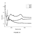
- FIG. 10 depicts a second set of FTIR scans of LiBO 2 films fabricated at 500° C., 750° C. and 900° C.;
- FIG. 11 depicts a schematic of the equivalent circuit used to model the impedance spectroscopy results presented in FIG. 12 .
- FIG. 12 depicts a characteristic impedance spectrograph of a LiBO 2 film at room temperature.
- the present method deposits an amorphous film of LiBO 2 (lithium metaborate) as an electrolyte directly onto an active electrode substrate, such as LiCoO 3 or V 2 O 5 .
- the method may use combustion chemical vapor deposition (“CCVD”), sometimes known as Flame Spray Pyrolysis.
- CCVD combustion chemical vapor deposition
- Flame Spray Pyrolysis sometimes known as Flame Spray Pyrolysis.
- the film may be deposited at different temperatures.
- a deposition apparatus 10 includes supply tanks 12 that pass combustion fuel gases through flow controllers 14 to a combustion device 16 , which burns the supply gases.
- a pump 20 pumps a reagent mixture 22 through the burning flame 24 .
- the reagent mixture is ignited, thereby converting the precursors into LiBO 2 in flight.
- the material then lands on the substrate 30 and cools, thereby forming a thin film 32 .
- FIG. 2 depicts a closer view of the deposition process.
- the supply gases pass through outlets 34 and are ignited to form the flame 24 .
- the reagent mixture is formed by mixing a solution of a combustible fluid (typically an alcohol having small amounts of water, such as ethanol, methanol, or isopropanol) with fluid-soluble lithium (LiNo 3 ) and boron (BCl 3 ) compounds.
- the lithium and boron compounds dissolve in the fluid to form a reagent mixture.
- the reagent mixture is sprayed through the nozzle 38 to form a liquid spray containing the reagent mixture.
- Atomized droplets 40 of the reagent mixture pass through the flame 24 , thereby forming heated lithium metaborate droplets.
- the heated droplets are then deposited onto a substrate 30 to form a thin film 32 of LiBO 2 .
- the substrate is an active electrode, such as LiCoO 2 or graphite
- the LiBO 2 acts as an electrolyte
- the resulting film may be amorphous.
- the substrate is removed from the flame following deposition, and the LiBO 2 coated side of the assembly is adhered to a positive electrode, for example by hot pressing, CCVD or chemical vapor deposition. The result is an intercalated lithium battery.
- FIG. 3 schematically depicts the steps used to make the intercalated battery according to one embodiment of the present methods.
- the method begins with an N-type silicon wafer 50 .
- the wafer 50 is etched (Step 1 ), and gold deposited over the entire surface of the wafer.
- a layer 52 of LiCoO2 is then deposited on the wafer 50 (Step 3 ) using CCVD, and a LiBO layer 54 deposited on top of the LiCoO2 (Step 4 ), as previously discussed with respect to FIGS. 1 and 2 .
- a layer 56 of V2O5 is deposited onto the wafer (Step 5 ), following which a gold current collector 58 is deposited (Step 6 ), completing the basic battery construction steps.
- FIG. 4 is an optical photograph of the Au/Si/Au/LiCoO 2 /LiBO 2 /V 2 O 5 /Au test cell.
- the test cell measured approximately 5 mm ⁇ 5 mm ⁇ 0.5 mm, 97% of which was inactive substrate.
- the thin film nature of the cell allows it to be deposited on a variety of substrates for maximum utility.
- FIG. 5 is an energy dispersive X-ray spectrograph of the test cell. Sharp peaks associated with polycrystalline cobalt can be seen at approximately 0.8 keV and 6.9 keV. Similarly, peaks associated with polycrystalline vanadium are evident at 4.9 and 5.4 keV. Lithium does not show up as it is too small to be imaged effectively by EDXS while the boron is contained in an amorphous film, rendering it invisible to X-ray analysis.
- FIG. 6 shows chronoamperometry curves of the Au/Si/Au/LiCoO2/LiBO 2 /V2O5/Au test cell.
- the current was held at +1 ⁇ A for 150 s and subsequently reversed to ⁇ 1 ⁇ A for 50 s.
- FIG. 7 is a self-discharge curve of the test cell shown in FIG. 4 .
- the current was held at +10 nA for 2500 s to charge and the switched to open circuit for 5500 s. The voltage drop over this period indicates that the leakage current is non-zero.
- Lithium nitrate (LiNO 3 ) and Boron trichloride (BCl 3 ) were measured and dissolved in ethanol to create a precursor solution of 0.025M.
- the solution pH was raised from pH 3 to pH 7 with ammonium hydroxide prior to deposition.
- the solution Prior to utilization in the CCVD system (the deposition apparatus 10 schematically depicted in FIG. 1 ), the solution was placed in an ultrasonic bath for 20 minutes to ensure complete dissolution of solute and to eliminate agglomeration.
- the solution was then deposited onto substrates using the deposition apparatus 10 .
- a magnetic stir bar was used to prevent solute particles from settling.
- Oxygen and methane in a 4:1 ratio provided the feed gas for the CCVD flame 24 .
- the deposition time was held constant at 20 minutes for each sample.
- the deposition temperature was changed to produce multiple unique LiBO 2 films.
- the resulting LiBO 2 films were thus fabricated entirely in an ambient, or open air, environment. Each film was extensively characterized by scanning electron microscopy (SEM), impedance spectroscopy and Fourier transform infrared spectroscopy (FTIR).
- FIGS. 8 a - f present planar and cross-sectional SEM images of LiBO 2 thin films.
- the cell encompassed an active area of 2 mm ⁇ 2 mm with a LiBO 2 electrolyte thickness of approximately 1 ⁇ m.
- FIG. 8 ( a - f ) are SEM micrographs of the LiBO 2 films developed via CCVD at fabrication temperatures of 500° C. ( FIGS. 8 a,b ), 750° C. ( FIGS. 8 c,d ) and 900° C. ( FIGS. 8 e,f ).
- the thin films of LiBO 2 were characterized using IR reflectance spectra. Infrared reflectance measurements were recorded with a Bomem DA3 spectrometer with an evacuated chamber and an MCT detector. A silicon carbide glowbar served as the beam source with a CaF2 beam splitter. The variable reflection angle was fixed at 30°, yielding a wavelength resolution of 4 cm ⁇ 1 . Each IR spectra was compiled from 100 scans of the sample.
- the IR reflectance peaks for LiBO 2 films deposited at 500° C., 750° C. and 900° C. are displayed in FIGS. 9 and 10 .
- Strong peaks at wavelengths of 1420 cm ⁇ 1 , 1440 cm ⁇ 1 and 1590 cm ⁇ 1 are associated with the crystalline phase of ⁇ -LiBO 2 .
- the films deposited at 750° C. show both a strong double peak at 1420 cm ⁇ 1 and 1440 cm ⁇ 1 and a secondary peak at 1590 cm ⁇ 1 indicating a large presence of crystalline ⁇ -LiBO 2 .
- Changes in film thickness may be attributable to changes in the working distance during fabrication.
- flame conditions were held constant throughout the film fabrication process. As such, fabrication temperature was adjusted by moving the substrate nearer to or farther from the flame. Because the deposition geometry is roughly conical, deposition closer to the spray nozzle will result in a slightly higher deposition rate. It should be noted that the total change in position, between the nearest and furthest deposition positions, totaled 35 mm or roughly 10.3% of the total nozzle to substrate distance.
- the LiBO 2 films were deposited atop a gold coated n-type silicon wafer.
- Silicon substrates were prepared by etching the native SiBO 2 layer in a 5% HF bath for 20 minutes. Once cleaned, substrates were immediately covered with gold on both sides using DC sputtering. Electrical measurements prior to LiBO 2 deposition confirmed a negligible resistance vertically through the Si wafer. The wafer was then diced and cleaned for deposition of the electrolyte. After LiBO 2 deposition, a matching Au electrode was sputtered atop the electrolyte for electrochemical testing.
- LiBO 2 thin films were characterized electrochemically in air via impedance spectroscopy. Electrical contacts were made by placing the symmetric cell between two spring loaded platinum mesh electrodes.
- a computer interface controlling a Gamry PCI4-750 Potentiostat board and controller board collected data over a frequency range from 100 kHz to 1 mHz using a two-electrode configuration.
- Impedance measurements of LiBO 2 films formed at 500° C. and 750° C. displayed a small real resistance of less than 1 ohm with an inductive component. This type of impedance spectra reflects a short circuit within the system, indicating that these layers were not sufficiently dense to prevent the positive electrode from touching the negative. Conversely, impedance spectrographs of LiBO 2 films deposited at 900° C. showed a single large interfacial polarization loop peaking near 7943 Hz with very little ohmic resistance.
- FIG. 12 is a characteristic impedance spectrograph of the LiBO 2 film at room temperature. This film was fabricated at 900° C. Because the impedance curve did not cross the real axis at low frequencies due to the onset of Warburg impedance, a simplified equivalent circuit simulation was used to estimate the polarization resistance, Rp. FIG. 11 presents a schematic of the equivalent circuit.
- LiBO 2 cell resistance 1.3e5 ohms was recorded for a LiBO 2 cell of dimensions of 2 mm ⁇ 1.5 mm ⁇ 1.5 ⁇ m.
- the experimental conductivity of 3.84e-8 S/cm falls within published values for LiBO 2 of 3.18e-8 to 7.78e-7.
- the wide range in LiBO 2 ionic conductivity is a reflection of differing lithium contents implying that the LiBO 2 film developed here may be slightly lithium deficient. While the ionic conductivity of LiBO 2 falls below that for LiPON electrolytes of 2.3e-6 S/cm, the higher electrical resistivity 10-12 for LiBO 2 vs. 10-8-10-9 for LiPON, makes it a viable electrolyte material.
- a higher electrical resistivity means that thinner films can be used without shorting the system.
- the present methods may be used to fabricate thin films of LiBO 2 using CCVD.
- the films may be porous and polycrystalline, but films deposited at 900° C. were amorphous and dense.
- the films were imaged with SEM, characterized with IR adsorption spectroscopy and electrochemically evaluated with impedance spectroscopy.
- LiBO 2 films developed at 900° C. showed a conductivity of 3.84e-8S/cm, well within the published range for this material
- LiBO 2 electrolytes fabricated by CCVD have been developed at a deposition rate of roughly 400 ⁇ /minute, more than two orders of magnitude faster than the average rates for CVD, PLD or sputtering systems. When pumpdown and system prep times are included, the deposition rate for traditional thin film methods falls even further.
- CCVD has already been developed as a continuous throughput system. By switching from a batch process to a continuous deposition process, output can be significantly increased, thereby improving the return on investment.
- the present method for fabricating an intercalated lithium battery without the assistance of a controlled environment comprises the following steps: (a) providing a substrate to serve as the negative electrode having at least one surface to be coated; (b) selecting a reagent and a carrier medium and mixing together said reagent and said carrier medium to form a reagent mixture, the reagent being selected such that at least a portion of the reagent forms a lithium boride coating; (c) spraying the reagent mixture through a nozzle to forms a liquid spray containing the reagent mixture; (d) passing said spray or vapor through a flame such that the reagent mixture is combusted; e) locating said substrate in a zone located relative to said liquid spray or vapor such that the surface temperature of the substrate is between 850° C.
- the negative electrode may be a graphite film or Lithium cobaltite.
- the positive electrode may be a vanadium oxide film. The order in which the positive and negative electrodes are deposited may be switched.
- the deposition method used may be combustion chemical vapor deposition.
- the carrier medium may be a liquid organic solvent.
- the reagent may be a gas, a vapor, or a liquid and said carrier is a gas, a vapor, or a liquid.
- the coating may comprise a combination of vapor deposited and spray pyrolysis deposited film of said reagent.
- the coating may also comprised spray pyrolysis deposited film of the reagent.
- the coating may be less than about 100 microns in thickness, or less than about 1 microns in thickness.
- the substrate may be heated predominately by the heat of combustion produced by combusting said reagent mixture, or by a secondary heat source.
- the deposition and irradiation typically occurs at a pressure between 10 torr and 10,000 torr.
Abstract
A method for fabricating intercalated lithium batteries in open air deposits a thin dense layer of amorphous solid-state lithium boride electrolyte directly onto a negative electrode via flame spray pyrolysis. In one embodiment, the negative electrode is attached to a prefabricated positive electrode via hot pressing (embossing), thus forming an intercalated lithium battery. The method significantly improves upon current methods of fabricating thin film solid state batteries by permitting fabrication without the aid of a controlled environment, thereby allowing for significantly cheaper fabrication than prior batch methods.
Description
This application claims priority based on U.S. Provisional Patent Application Ser. No. 61/611,139 filed Mar. 15, 2012 and titled “Open Air Method for the Fabrication of Intercalated Lithium Batteries,” the disclosure of which is incorporated herein by this reference.
This invention relates to an improved process for manufacturing lithium batteries, and in particular a process that may be employed in an open environment.
Batteries are comprised of a positive and a negative electrode separated by an ionically conductive, but electrically insulating, electrolyte. Secondary batteries are further defined by reversible electrochemical reactions. Secondary batteries come in a wide variety of types and sizes, but are generally defined by the mobile ion. Thus, lithium secondary batteries typically rely upon conduction of the mobile lithium ion, Li+.
Typically, liquid electrolyte lithium batteries are fabricated under vacuum conditions because both the electrolyte, such as LiPF6, and the metallic lithium negative electrode react violently with moisture in the ambient atmosphere. Solid state lithium batteries are also manufactured under vacuum conditions due to two important factors. First, the most popular electrolyte and electrode materials for solid state batteries also react with moisture. In fact, many thin film batteries use lithium metal as the negative electrode and Lithium cobaltite (LiCoO2) as the positive electrode. Second, solid state batteries depend on an amorphous thin film electrolyte, for which there are few known methods of fabrication.
Previous studies of thin film lithium batteries often focused on the use of lithium phosphorus oxynitride (LiPON) as the electrolyte. The relatively high ionic conductivity and stability in contact with metallic lithium make LiPON a popular choice. Ionic conductivity, however, is heavily dependant on the nitrogen content and thus is limited to vacuum deposition methods.
Two alternate electrolyte materials, lithium metaborate (LiBO2) and lithium sulfide (Li2S) glasses, have also been found to be good lithium ion conductors. Although they provide good conductivity, sulfide glasses tend to be unstable both in contact with lithium metal and under atmospheric conditions. LiBO2 electrolytes have also been found to be unstable with lithium metal but do not typically have similar problems under atmospheric conditions. It was also been found that phosphorous additives, such as P2O5, can further increase the ionic conductivity.
Similar to liquid electrolyte batteries, most solid state lithium batteries utilize metallic lithium as a negative electrode. Metallic lithium is popular because it supplies a high electrochemical potential and thus open circuit voltage (OCV). Although toxic, corrosive and flammable, lithium metal can be manipulated under a controlled environment.
Alternatively, thin film batteries can be developed as an intercalated, or rocking chair, battery. The intercalated battery is a specific type of secondary lithium battery in which both the anode and cathode are formed with intercalation compounds rather than metallic lithium. In this case, the elemental lithium is impregnated, or intercalated, in an oxide rather than applied directly. The lithium ions then move back and forth between interstitial sites as the battery is charged and discharged. While this often reduces the open circuit voltage (OCV) of the cell, intercalated batteries have found niche applications due to improved safety characteristics and power-to-weight ratios.
More recently, lithium impregnated materials have been investigated as potential electrode materials. In 1995 it was shown that the high temperature phase of LiCoO2 shows good stability and reversibility. Oriented vanadium (III) oxide has also been shown to be a potential electrode material.
For solid electrolytes, amorphous thin films are typically preferred because grain boundaries tend to inhibit lithium ion movement within the electrolyte. Because lithium is propagated in solid state ionic conductors by an interstitial method, amorphous or nanocrystalline materials show consistently higher ionic conductivity than do their crystalline counterparts. Unfortunately, only select techniques are capable of depositing thin amorphous films. To this point, the deposition of dense, amorphous, lithium-containing films has often used vacuum or controlled environment processes.
In the last several years, numerous thin film lithium batteries have been developed and commercialized. Thin films are usually considered to be less than 10 microns thick. The Handbook of Thin-Film Deposition Processes and Techniques (Noyes Pubs. 1988; Schuegraf, K. K. editor) provides a broad review of thin-film deposition techniques. These technologies include chemical vapor deposition, pulsed laser deposition, e-beam evaporation and DC/RF sputtering.
Some of the first thin film lithium batteries were developed based on an amorphous lithium phosphosilicate electrolyte. Unfortunately this electrolyte was unstable in contact with metallic lithium and little progress was made until the advent of lithium phosphorus oxynitride (LiPON). LiPON electrolytes were found to be stable up to 5.5V versus lithium metal, which encouraged the development of experimental prototypes. Lithium boride (LiBO2) and lithium sulfide (Li2S) glasses were also found to be good lithium ion conductors. While providing excellent conductivity, sulfide glasses were shown to be unstable both in contact with lithium metal and under atmospheric conditions. In contrast, LiBO2 electrolytes were found to be unstable with lithium metal but did not have similar problems under atmospheric conditions.
A variety of intercalated electrodes were developed to replace lithium metal. In 1995 it was shown that the high temperature phase of LiCoO2 shows good stability and reversibility. More recently oriented Vanadium (III) Oxide was shown to be a potential electrode material.
Solid state intercalated lithium batteries are typically manufactured in a controlled environment using thin film deposition methods such as chemical vapor deposition, pulsed laser deposition, DC/RF magnetron sputtering or e-beam evaporation. Such time and energy intensive methods are required due to the material choices and the difficulty in producing amorphous lithium ion conductors. However, thin film intercalated lithium batteries could be produced much more cheaply and efficiently if thin film, amorphous electrolytes could be developed in the ambient atmosphere.
The present disclosure provides a method for manufacturing an intercalated lithium battery in an open environment. In contrast to prior methods, the present method uses combustion chemical vapor deposition (“CCVD”), also known as flame spray pyrolysis, to deposit LiBO2 electrolytes. The method takes advantage of the fact that LiBO2 films deposited between 850° C. and 1000° C. are dense, amorphous and stoichiometrically precise. Because CCVD does not require a controlled atmosphere, the present method can be performed in open air. When combined with intercalated electrodes, a solid state lithium battery may be fabricated entirely in the ambient atmosphere. Ultimately, this should reduce fabrication costs and increase process speeds by allowing battery manufacturers to switch from a batch process to a continuous rolling process.
The present method includes a multi-step method for the fabrication of intercalated lithium batteries in open air. First, a negative current collector and negative electrode (or anode) assembly is prefabricated. Next, an amorphous, dense lithium boride electrolyte is deposited atop the negative electrode via flame spray pyrolysis. The thickness of this film is typically between 100 nm and 50 μm and is sufficiently continuous to prevent contact between the positive and negative electrodes.
Next, the positive electrode (or cathode) is deposited on top of the lithium boride electrolyte to form a negative current collector/negative electrode/electrolyte/positive electrode assembly. Finally, a positive current collector is deposited atop the positive electrode assembly to form a working lithium battery having the cross-sectional structure negative current collector/negative electrode/electrolyte/positive electrode/positive current collector. Alternatively, the negative electrode/negative current collector assembly may also be prefabricated and bonded directly to the positive current collector/positive electrode/electrolyte assembly. Of special note is that all parts of this process are developed in the ambient atmosphere.
Specifically, according to the present method, an intercalated lithium battery is produced in an ambient atmosphere by first providing a substrate to serve as the negative electrode. The substrate has at least one surface that may be coated. The substrate may be formed from a variety of materials, such as LiCoO2, the principal requirements being that the substrate be electrically conductive and capable of holding or storing lithium, because the battery stores lithium on both the anode and the cathode, depending on the state of charge of the battery.
An amorphous layer of LiBO2 (lithium metaborate) is formed by CCVD. The process begins by mixing a solution of a combustible fluid (typically an alcohol solution, such as ethanol methanol, or isopropanol) with fluid-soluble lithium and boron compounds. Examples of such compounds are LiNO3 and BCl3. The lithium and boron compounds dissolve in the fluid to form a reagent mixture. The reagent mixture is sprayed through a nozzle to a liquid spray containing the reagent mixture. The spray passes through a flame to combust the reagent mixture, thereby forming heated lithium metaborate.
The lithium metaborate deposits onto the substrate at a temperature between 750 C and 1100 C, where it cools to form an amorphous lithium metaborate coating on the substrate. The substrate is removed from the flame following deposition, and adhered to a positive electrode, for example by hot pressing. The result is an intercalated lithium battery. Alternatively, the positive electrode can be directly deposited atop the electrolyte by any thin film deposition method, such as CCVD, CVD or sputtering.
There are several alternative ways of producing the battery. For example, the order in which the positive and negative electrodes are deposited may be reversed. The positive electrode may be made of one of several common positive electrode materials, such as is V2O5, LiCoO2, manganese spinel, lithiated transition metal oxide compounds, LiNiO2 or lithium manganese oxide. The negative electrode may be any of several common electrodes, such that the standard potential of the negative electrode is sufficiently less than that of the positive electrode. Common negative electrodes are LiCoO2, carbon black, graphite, graphene, carbon nanotubes, silicon carbide or disordered carbon compounds.
Other features and advantages of the present invention will be apparent from reference to the following Detailed Description taken in conjunction with the accompanying Drawings, in which:
According to one embodiment, the present method deposits an amorphous film of LiBO2 (lithium metaborate) as an electrolyte directly onto an active electrode substrate, such as LiCoO3 or V2O5. The method may use combustion chemical vapor deposition (“CCVD”), sometimes known as Flame Spray Pyrolysis. The film may be deposited at different temperatures.
As depicted in FIG. 1 , a deposition apparatus 10 includes supply tanks 12 that pass combustion fuel gases through flow controllers 14 to a combustion device 16, which burns the supply gases. At the same time, a pump 20 pumps a reagent mixture 22 through the burning flame 24. The reagent mixture is ignited, thereby converting the precursors into LiBO2 in flight. The material then lands on the substrate 30 and cools, thereby forming a thin film 32.
When lithium metaborate deposits onto the substrate at a temperature between 750 C and 1100 C, the resulting film may be amorphous. The substrate is removed from the flame following deposition, and the LiBO2 coated side of the assembly is adhered to a positive electrode, for example by hot pressing, CCVD or chemical vapor deposition. The result is an intercalated lithium battery.
Initial Performance Curves
Molar quantities of precursor components of Lithium nitrate (LiNO3) and Boron trichloride (BCl3) were measured and dissolved in ethanol to create a precursor solution of 0.025M. The solution pH was raised from pH 3 to pH 7 with ammonium hydroxide prior to deposition. Prior to utilization in the CCVD system (the deposition apparatus 10 schematically depicted in FIG. 1 ), the solution was placed in an ultrasonic bath for 20 minutes to ensure complete dissolution of solute and to eliminate agglomeration.
The solution was then deposited onto substrates using the deposition apparatus 10. During deposition, a magnetic stir bar was used to prevent solute particles from settling. Oxygen and methane in a 4:1 ratio provided the feed gas for the CCVD flame 24. The deposition time was held constant at 20 minutes for each sample. The deposition temperature was changed to produce multiple unique LiBO2 films. The resulting LiBO2 films were thus fabricated entirely in an ambient, or open air, environment. Each film was extensively characterized by scanning electron microscopy (SEM), impedance spectroscopy and Fourier transform infrared spectroscopy (FTIR).
Following deposition, the thin film cells were imaged with Scanning Electron Microscopy (SEM) and evaluated with impedance spectroscopy. SEM images were taken using a Hitachi 4100 Field Emission Microscope. A thin carbon coating was deposited via RF sputtering prior to introduction into the vacuum chamber in order to reduce charging of the substrate during imaging. FIGS. 8 a-f present planar and cross-sectional SEM images of LiBO2 thin films. The cell encompassed an active area of 2 mm×2 mm with a LiBO2 electrolyte thickness of approximately 1 μm. FIG. 8 (a-f) are SEM micrographs of the LiBO2 films developed via CCVD at fabrication temperatures of 500° C. (FIGS. 8 a,b), 750° C. (FIGS. 8 c,d) and 900° C. (FIGS. 8 e,f).
The thin films of LiBO2 were characterized using IR reflectance spectra. Infrared reflectance measurements were recorded with a Bomem DA3 spectrometer with an evacuated chamber and an MCT detector. A silicon carbide glowbar served as the beam source with a CaF2 beam splitter. The variable reflection angle was fixed at 30°, yielding a wavelength resolution of 4 cm−1. Each IR spectra was compiled from 100 scans of the sample.
The IR reflectance peaks for LiBO2 films deposited at 500° C., 750° C. and 900° C. are displayed in FIGS. 9 and 10 . Strong peaks at wavelengths of 1420 cm−1, 1440 cm−1 and 1590 cm−1 are associated with the crystalline phase of α-LiBO2. In FIG. 9 , the films deposited at 750° C. show both a strong double peak at 1420 cm−1 and 1440 cm−1 and a secondary peak at 1590 cm−1 indicating a large presence of crystalline α-LiBO2. Films deposited at 500° C. showed similar peaks at 1420 cm−1, 1440 cm−1 and 1590 cm−1, but with less intensity. This may be a result of a thinner film due to differences in deposition rates. Conversely, films deposited at 900° C. showed none of these peaks and more clearly reflected the spectrum for amorphous LiBO2.
Changes in film thickness may be attributable to changes in the working distance during fabrication. To minimize the number of independent variables, flame conditions were held constant throughout the film fabrication process. As such, fabrication temperature was adjusted by moving the substrate nearer to or farther from the flame. Because the deposition geometry is roughly conical, deposition closer to the spray nozzle will result in a slightly higher deposition rate. It should be noted that the total change in position, between the nearest and furthest deposition positions, totaled 35 mm or roughly 10.3% of the total nozzle to substrate distance.
For electrochemical measurements, the LiBO2 films were deposited atop a gold coated n-type silicon wafer. Silicon substrates were prepared by etching the native SiBO2 layer in a 5% HF bath for 20 minutes. Once cleaned, substrates were immediately covered with gold on both sides using DC sputtering. Electrical measurements prior to LiBO2 deposition confirmed a negligible resistance vertically through the Si wafer. The wafer was then diced and cleaned for deposition of the electrolyte. After LiBO2 deposition, a matching Au electrode was sputtered atop the electrolyte for electrochemical testing.
LiBO2 thin films were characterized electrochemically in air via impedance spectroscopy. Electrical contacts were made by placing the symmetric cell between two spring loaded platinum mesh electrodes. A computer interface controlling a Gamry PCI4-750 Potentiostat board and controller board collected data over a frequency range from 100 kHz to 1 mHz using a two-electrode configuration.
Impedance measurements of LiBO2 films formed at 500° C. and 750° C. displayed a small real resistance of less than 1 ohm with an inductive component. This type of impedance spectra reflects a short circuit within the system, indicating that these layers were not sufficiently dense to prevent the positive electrode from touching the negative. Conversely, impedance spectrographs of LiBO2 films deposited at 900° C. showed a single large interfacial polarization loop peaking near 7943 Hz with very little ohmic resistance.
At room temperature, a total cell resistance of 1.3e5 ohms was recorded for a LiBO2 cell of dimensions of 2 mm×1.5 mm×1.5 μm. The experimental conductivity of 3.84e-8 S/cm falls within published values for LiBO2 of 3.18e-8 to 7.78e-7. The wide range in LiBO2 ionic conductivity is a reflection of differing lithium contents implying that the LiBO2 film developed here may be slightly lithium deficient. While the ionic conductivity of LiBO2 falls below that for LiPON electrolytes of 2.3e-6 S/cm, the higher electrical resistivity 10-12 for LiBO2 vs. 10-8-10-9 for LiPON, makes it a viable electrolyte material. A higher electrical resistivity means that thinner films can be used without shorting the system.
Thus, the present methods may be used to fabricate thin films of LiBO2 using CCVD. At 500° C. and 750° C., the films may be porous and polycrystalline, but films deposited at 900° C. were amorphous and dense. The films were imaged with SEM, characterized with IR adsorption spectroscopy and electrochemically evaluated with impedance spectroscopy. LiBO2 films developed at 900° C. showed a conductivity of 3.84e-8S/cm, well within the published range for this material
In contrast to alternative methods for LiBO2 fabrication, these films were developed in an open air environment. Two advantages of this method versus vacuum or controlled environment methods are cost and speed. By working in open air, up-front plant construction costs may be significantly reduced.
Most thin film batteries are more expensive than their liquid electrolyte counterparts because the fabrication process incurs non-trivial costs. Maintaining a high vacuum during fabrication is a time and energy intensive proposition. Multiple vacuum pumps, specialty materials and relatively small chamber sizes are needed to minimize outgassing and maintain a controlled environment. Moving from vacuum deposition to open air fabrication reduces these problems thereby significantly lowering the upfront plant costs. Because raw materials can make up 70-80% of the cost of a battery, few businesses are interested in such a low margin product. However, by significantly cutting the up-front costs, a much higher return on investment can be seen.
Furthermore, LiBO2 electrolytes fabricated by CCVD have been developed at a deposition rate of roughly 400 Å/minute, more than two orders of magnitude faster than the average rates for CVD, PLD or sputtering systems. When pumpdown and system prep times are included, the deposition rate for traditional thin film methods falls even further. On the other hand, CCVD has already been developed as a continuous throughput system. By switching from a batch process to a continuous deposition process, output can be significantly increased, thereby improving the return on investment.
Therefore, the present method for fabricating an intercalated lithium battery without the assistance of a controlled environment comprises the following steps: (a) providing a substrate to serve as the negative electrode having at least one surface to be coated; (b) selecting a reagent and a carrier medium and mixing together said reagent and said carrier medium to form a reagent mixture, the reagent being selected such that at least a portion of the reagent forms a lithium boride coating; (c) spraying the reagent mixture through a nozzle to forms a liquid spray containing the reagent mixture; (d) passing said spray or vapor through a flame such that the reagent mixture is combusted; e) locating said substrate in a zone located relative to said liquid spray or vapor such that the surface temperature of the substrate is between 850° C. and 1000° C.; (e) removing said substrate from the flame following deposition; f) adhering a positive electrode to the coated surface of the substrate via hot pressing to form an intercalated lithium battery. The negative electrode may be a graphite film or Lithium cobaltite. The positive electrode may be a vanadium oxide film. The order in which the positive and negative electrodes are deposited may be switched.
Furthermore, the deposition method used may be combustion chemical vapor deposition. The carrier medium may be a liquid organic solvent. The reagent may be a gas, a vapor, or a liquid and said carrier is a gas, a vapor, or a liquid. The coating may comprise a combination of vapor deposited and spray pyrolysis deposited film of said reagent. The coating may also comprised spray pyrolysis deposited film of the reagent. The coating may be less than about 100 microns in thickness, or less than about 1 microns in thickness. The substrate may be heated predominately by the heat of combustion produced by combusting said reagent mixture, or by a secondary heat source. The deposition and irradiation typically occurs at a pressure between 10 torr and 10,000 torr.
The present methods have several advantages over prior methods. Although embodiments of the present methods have been described, various modifications and changes may be made by those skilled in the art without departing from the spirit and scope of the invention.
Claims (18)
1. A method for fabricating an intercalated lithium battery without the assistance of a controlled environment comprising the steps of:
(a) providing a substrate to serve as the negative electrode having at least one surface to be coated;
(b) forming a layer of amorphous LiBO2 (lithium metaborate) directly on the at least one surface of the substrate by:
mixing a solution of a combustible fluid with fluid-soluble lithium and boron compounds to dissolve the compounds in the fluid to form a reagent mixture;
spraying the reagent mixture through a nozzle to form a liquid spray containing the reagent mixture;
passing the spray through a flame to combust the reagent mixture, thereby forming heated lithium metaborate;
depositing the lithium metaborate onto the substrate at a temperature between 750° C and 1100° C to form an amorphous lithium metaborate coating on the substrate;
(c) removing the coated substrate from the flame following deposition; and
(d) directly adhering a positive electrode configured to accept lithium ions to the layer of amorphous LiBO2 to form an intercalated lithium battery.
2. The method of claim 1 wherein the lithium metaborate is deposited onto the substrate at a temperature of between 850° C. and 1000° C.
3. The method of claim 1 wherein the negative electrode is made of graphite or graphene.
4. The method of claim 1 wherein the positive electrode is made of vanadium oxide.
5. The method of claim 1 wherein the negative electrode is made of LiCoO2.
6. The method of claim 1 wherein the positive electrode is adhered by hot pressing, chemical vapor deposition, RF Sputtering, DC Sputtering or Pulsed Laser Deposition.
7. The method of claim 1 wherein the combustible fluid comprises an alcohol.
8. The method of claim 1 wherein the combustible fluid comprises an organic solvent.
9. The method of claim 1 where the fluid soluble lithium compound is LiNO3.
10. The method of claim 1 where the fluid soluble boron compound is BCl3.
11. The method of claim 1 where the positive electrode comprises at least one of V2O5, LiCoO2, Manganese spinel compounds, LiNiO2, Lithium Manganese oxide, or Lithiated transition metal oxides.
12. The method of claim 1 where the negative electrode comprises at least one of LiCoO2, carbon black, graphite, graphene, carbon nanotubes, silicon carbide or disordered carbon compounds.
13. A method for fabricating an intercalated lithium battery without the assistance of a controlled environment comprising the steps of:
(a) providing a substrate to serve as the positive electrode having at least one surface to be coated;
(b) forming a layer of amorphous LiBO2 (lithium metaborate) directly on the at least one surface of the substrate by:
mixing a solution of a combustible fluid with fluid-soluble lithium and boron compounds to dissolve the compounds in the fluid to form a reagent mixture;
spraying the reagent mixture through a nozzle to form a liquid spray containing the reagent mixture;
passing the spray through a flame to combust the reagent mixture, thereby forming heated lithium metaborate;
depositing the lithium metaborate onto the substrate at a temperature between 750° C and 1100° C to form an amorphous lithium metaborate coating on the substrate;
(c) removing the coated substrate from the flame following deposition; and
(d) directly adhering a negative electrode configured to accept lithium ions to the layer of amorphous LiBO2 to form an intercalated lithium battery.
14. The method of claim 13 wherein the lithium metaborate is deposited onto the substrate at a temperature of between 850° C and 1000° C.
15. The method of claim 13 wherein the negative electrode is adhered by hot pressing, chemical vapor deposition, RF Sputtering, DC Sputtering or Pulsed Laser Deposition.
16. The method of claim 13 wherein the combustible fluid comprises at least one of an alcohol or an organic solvent.
17. The method of claim 13 where the positive electrode comprises at least one of V205, LiCoO, Manganese spinel compounds, LiNiO2, Lithium Manganese oxide, or Lithiated transition metal oxides.
18. The method of claim 13 where the negative electrode comprises at least one of LiCoO2, carbon black, graphite, graphene, carbon nanotubes, silicon carbide or disordered carbon compounds.
Priority Applications (4)
| Application Number | Priority Date | Filing Date | Title |
|---|---|---|---|
| US13/777,922 US9450239B1 (en) | 2012-03-15 | 2013-02-26 | Methods for fabrication of intercalated lithium batteries |
| US14/990,307 US10573931B2 (en) | 2012-03-15 | 2016-01-07 | Intercalated lithium batteries |
| US15/266,732 US10340554B2 (en) | 2012-03-15 | 2016-09-15 | Methods for fabrication of intercalated lithium batteries |
| US16/776,987 US20200168942A1 (en) | 2012-03-15 | 2020-01-30 | Electrolytes for intercalated lithium batteries |
Applications Claiming Priority (2)
| Application Number | Priority Date | Filing Date | Title |
|---|---|---|---|
| US201261611139P | 2012-03-15 | 2012-03-15 | |
| US13/777,922 US9450239B1 (en) | 2012-03-15 | 2013-02-26 | Methods for fabrication of intercalated lithium batteries |
Related Child Applications (2)
| Application Number | Title | Priority Date | Filing Date |
|---|---|---|---|
| US14/990,307 Division US10573931B2 (en) | 2012-03-15 | 2016-01-07 | Intercalated lithium batteries |
| US15/266,732 Continuation US10340554B2 (en) | 2012-03-15 | 2016-09-15 | Methods for fabrication of intercalated lithium batteries |
Publications (1)
| Publication Number | Publication Date |
|---|---|
| US9450239B1 true US9450239B1 (en) | 2016-09-20 |
Family
ID=55792713
Family Applications (4)
| Application Number | Title | Priority Date | Filing Date |
|---|---|---|---|
| US13/777,922 Active 2034-09-09 US9450239B1 (en) | 2012-03-15 | 2013-02-26 | Methods for fabrication of intercalated lithium batteries |
| US14/990,307 Expired - Fee Related US10573931B2 (en) | 2012-03-15 | 2016-01-07 | Intercalated lithium batteries |
| US15/266,732 Active 2033-10-20 US10340554B2 (en) | 2012-03-15 | 2016-09-15 | Methods for fabrication of intercalated lithium batteries |
| US16/776,987 Abandoned US20200168942A1 (en) | 2012-03-15 | 2020-01-30 | Electrolytes for intercalated lithium batteries |
Family Applications After (3)
| Application Number | Title | Priority Date | Filing Date |
|---|---|---|---|
| US14/990,307 Expired - Fee Related US10573931B2 (en) | 2012-03-15 | 2016-01-07 | Intercalated lithium batteries |
| US15/266,732 Active 2033-10-20 US10340554B2 (en) | 2012-03-15 | 2016-09-15 | Methods for fabrication of intercalated lithium batteries |
| US16/776,987 Abandoned US20200168942A1 (en) | 2012-03-15 | 2020-01-30 | Electrolytes for intercalated lithium batteries |
Country Status (1)
| Country | Link |
|---|---|
| US (4) | US9450239B1 (en) |
Cited By (1)
| Publication number | Priority date | Publication date | Assignee | Title |
|---|---|---|---|---|
| WO2022150096A3 (en) * | 2020-11-03 | 2022-11-24 | Research Foundation Of The City University Of New York | Device and method for utilizing intercalation zinc oxide with an electrode |
Families Citing this family (12)
| Publication number | Priority date | Publication date | Assignee | Title |
|---|---|---|---|---|
| JP2017004673A (en) * | 2015-06-08 | 2017-01-05 | セイコーエプソン株式会社 | Electrode composite, method for manufacturing electrode composite, and lithium battery |
| JP2017004672A (en) | 2015-06-08 | 2017-01-05 | セイコーエプソン株式会社 | Electrode composite, method for manufacturing electrode composite, and lithium battery |
| CN105932269B (en) * | 2016-05-24 | 2019-04-30 | 浙江美达瑞新材料科技有限公司 | The method that spray burning pyrolysis prepares anode material for lithium-ion batteries |
| CN108110192B (en) * | 2017-11-25 | 2020-12-04 | 合肥国轩高科动力能源有限公司 | Preparation method of lithium ion battery ceramic diaphragm |
| IT201800010128A1 (en) * | 2018-11-07 | 2020-05-07 | Eldor Corp Spa | SOLID STATE BATTERY |
| CN109698340B (en) * | 2018-12-28 | 2022-03-11 | 天能电池(芜湖)有限公司 | Preparation process of lithium ion battery made of nickel-cobalt-aluminum ternary cathode material |
| CN110491599B (en) * | 2019-08-05 | 2021-09-03 | 重庆文理学院 | Preparation method of composite conductive film |
| CN111521467B (en) * | 2020-06-04 | 2023-08-29 | 河北省地质实验测试中心 | Graphite detection method |
| CN112086632B (en) * | 2020-09-18 | 2022-10-11 | 杭州高烯科技有限公司 | Defect-state disordered-layer stacked graphene assembled battery material and preparation method thereof |
| CN112794370B (en) * | 2020-12-18 | 2022-02-11 | 北京当升材料科技股份有限公司 | Doped positive electrode material precursor, preparation method and application thereof, doped positive electrode material, preparation method and application thereof |
| CN113823791B (en) * | 2021-09-14 | 2023-03-28 | 西安交通大学 | Lithium-sulfur battery positive electrode barrier layer material and preparation method thereof |
| CN115207359B (en) * | 2022-09-13 | 2022-12-20 | 广州云通锂电池股份有限公司 | Lithium ion battery anode slurry, preparation method thereof and lithium ion battery |
Citations (9)
| Publication number | Priority date | Publication date | Assignee | Title |
|---|---|---|---|---|
| WO2000072398A1 (en) | 1999-05-25 | 2000-11-30 | Leading Edge Technologies, Inc. | Apparatus and method for battery cell electrode preparation, assembly and lamination |
| US20030008213A1 (en) | 2001-05-23 | 2003-01-09 | Samsung Sdi Co., Ltd. | Method for manufacturing lithium battery |
| US20040023106A1 (en) * | 2002-08-02 | 2004-02-05 | Benson Martin H. | Apparatus and method for fracture absorption layer |
| WO2005124919A2 (en) | 2004-06-14 | 2005-12-29 | The University Of Chicago | Methods for fabricating lithium rechargeable batteries |
| WO2006012575A2 (en) | 2004-07-22 | 2006-02-02 | Solicore, Inc. | Improved battery tab and packaging design |
| US20060024587A1 (en) | 2003-03-25 | 2006-02-02 | Sanyo Electric Co., Ltd. | Nonaqueous electrolyte solution for secondary battery and nonaqueous electrolyte secondary battery |
| DE102005038351A1 (en) | 2005-08-11 | 2007-02-15 | Siemens Ag | Electrochemical energy storage |
| DE102007041513A1 (en) | 2007-08-31 | 2009-03-05 | Hella Kgaa Hueck & Co. | Electrode arrangement including a copper electrode with a separator layer useful for electrical storage, e.g. in accumulators minimizes danger of shortcircuiting or accelerated self-discharge |
| US8007758B2 (en) * | 2003-05-20 | 2011-08-30 | Eth Zurich | Metal delivery system for nanoparticle manufacture |
Family Cites Families (4)
| Publication number | Priority date | Publication date | Assignee | Title |
|---|---|---|---|---|
| US8865271B2 (en) * | 2003-06-06 | 2014-10-21 | Neophotonics Corporation | High rate deposition for the formation of high quality optical coatings |
| US20070218333A1 (en) * | 2004-04-12 | 2007-09-20 | Kazuya Iwamoto | Metal-Oxide Containing Substrate and Manufacturing Method Therefor |
| US9172090B2 (en) * | 2010-05-07 | 2015-10-27 | Massachusetts Institute Of Technoloy | Electrochemical device comprising lithium manganese borate compounds |
| US9240585B2 (en) * | 2011-02-28 | 2016-01-19 | Applied Materials, Inc. | Manufacturing of high capacity prismatic lithium-ion alloy anodes |
-
2013
- 2013-02-26 US US13/777,922 patent/US9450239B1/en active Active
-
2016
- 2016-01-07 US US14/990,307 patent/US10573931B2/en not_active Expired - Fee Related
- 2016-09-15 US US15/266,732 patent/US10340554B2/en active Active
-
2020
- 2020-01-30 US US16/776,987 patent/US20200168942A1/en not_active Abandoned
Patent Citations (9)
| Publication number | Priority date | Publication date | Assignee | Title |
|---|---|---|---|---|
| WO2000072398A1 (en) | 1999-05-25 | 2000-11-30 | Leading Edge Technologies, Inc. | Apparatus and method for battery cell electrode preparation, assembly and lamination |
| US20030008213A1 (en) | 2001-05-23 | 2003-01-09 | Samsung Sdi Co., Ltd. | Method for manufacturing lithium battery |
| US20040023106A1 (en) * | 2002-08-02 | 2004-02-05 | Benson Martin H. | Apparatus and method for fracture absorption layer |
| US20060024587A1 (en) | 2003-03-25 | 2006-02-02 | Sanyo Electric Co., Ltd. | Nonaqueous electrolyte solution for secondary battery and nonaqueous electrolyte secondary battery |
| US8007758B2 (en) * | 2003-05-20 | 2011-08-30 | Eth Zurich | Metal delivery system for nanoparticle manufacture |
| WO2005124919A2 (en) | 2004-06-14 | 2005-12-29 | The University Of Chicago | Methods for fabricating lithium rechargeable batteries |
| WO2006012575A2 (en) | 2004-07-22 | 2006-02-02 | Solicore, Inc. | Improved battery tab and packaging design |
| DE102005038351A1 (en) | 2005-08-11 | 2007-02-15 | Siemens Ag | Electrochemical energy storage |
| DE102007041513A1 (en) | 2007-08-31 | 2009-03-05 | Hella Kgaa Hueck & Co. | Electrode arrangement including a copper electrode with a separator layer useful for electrical storage, e.g. in accumulators minimizes danger of shortcircuiting or accelerated self-discharge |
Non-Patent Citations (24)
| Title |
|---|
| Birke, A first approach to a monolithic all solid state inorganic lithium battery, Solid State Ionics 118, 149-157 (Dec. 1997). |
| Brodd, Factors Affecting U.S. Production Decisions: Why are There No Volume Lithium-Ion Battery Manufacturers in the United States?, ATP Working Paper Series Working Paper 05-01 (Jun. 2005). |
| Can, Electrical and optical properties of Li-doped LiBOa and LiNb03 films, Journal of Applied Physics 76, 4327 (1994). |
| Goldner, Development of a Thun Film LiCoo/LiC Rocking-Chair Batteries, Electrochemical SOciety Proceedings, vol. 95-22. |
| Horopantis Electrical Properties of Lithiated Boron Oxide Fast-ion Conducting Glasses, Ionics 9 (2003). |
| Huang, Vibrational spectroscopic and electrochemical studies of the low and high temperature phases of LiCo, Mo . . . , Solid State Ionics 86-88 (1996). |
| Hunt, Combustion chemical vapor deposition: A novel thin-film deposition technique, Appl. Phys. Lett. 63 (Jul. 12, 1993). |
| Inada, Fabrications and properties of composite solid-state electrolytes, Solid State Ionics 158 (2003) 275-280. |
| Joo, Thin film lithium ion conducting LiBSO solid electrolyte, Solid State Ionics 160 (2003) 51-59. |
| Kanehori, Thin Film Solid Electrolyte and Its Application to Secondary Lithium Cell, Solid State Ionics 9 & I0 (1983) 1445-1448. |
| Kang, Electrochemical and structural properties of HT-LiCoO2 and Lt-LiCoO2 prepared by the citrate sol-gel method, Solid State Ionics 120 (1999) 155-161. |
| Karan, Structural and lithium ion transport studies in borophosphate glasses, Solid State Ionics 177 (2006) 1429-1436. |
| Kuhn, Li Ion Diffusion in Nanocrystalline and Nanoglassy LiAlSi2O6 and LiBO2-Structure-Dynamics Relations in Two Glass Forming COmpounds, Z/ Phys. Chem. 223,1359-1377 (2009). |
| Lee, Modification of network structure induced by glass former composition and its correlation to the conductivity in lithium borophosphate glass for solid state electrolyte, Solid State Ionics 178 (2007) 375-379. |
| Lei, Pressure-induced coordination changes in LiBO2, Journal of Solid State Chemistry 182 (2009) 3041-3048. |
| Mathews, High-temperature behavior of lithium borates Part II: High-temperature X-ray diffractionometric and dilatometric studies, Thermochimica Acta 319 (1998) 113-121. |
| Mathews, High-temperature behavior of lithium borates: Part I: Characterization and thermal stability, Thermochimica Acta 320 (1998) 89-95. |
| McMillen, The hydrothermal synthesis, growth, and optical properties of g-LiBO2, Journal of Crystal Growth 310 (2008) 299-305. |
| Minami, Comparison of Ionic Conductivity Between Glassy and Crystalling Solid Electrolytes in the System Agl-AG20-MoO3, Journal of the American Cerasmic Society, Sep.-Oct. 1977, pp. 467-469. |
| Munoz, Increased electrical conductivity of LiPON glasses produced by ammonolysis, Solid State Ionics 179 (2008) 574-579. |
| Navone, A kinetic study of electrochemical lithium insertion into oriented V2O5 thin films prepared by rf sputtering, Electrochimica Acta 53 (2008) 3329-3336. |
| Thackeray, Lithiated Oxides for Lithium-Ion Batteries, paper to bepresented at the 186th Meeting, The Electrochemical Society Symposium, Oct. 9-14, 1994. |
| Tsuruhama, Preparation of Layered-Rhombohedral LiCoO2 Epitaxial Thin Films Using Pulsed Laser Deposition, Applied Physics Express 2 (2009) 085502. |
| Vaish, Crystallization Kinetics and Electrical Relaxation of BaO-0.5Li O-4.5B2O3 Glasses, J. Am. Ceram. Soc., 92 [9] 1993-1998 (2009). |
Cited By (1)
| Publication number | Priority date | Publication date | Assignee | Title |
|---|---|---|---|---|
| WO2022150096A3 (en) * | 2020-11-03 | 2022-11-24 | Research Foundation Of The City University Of New York | Device and method for utilizing intercalation zinc oxide with an electrode |
Also Published As
| Publication number | Publication date |
|---|---|
| US20200168942A1 (en) | 2020-05-28 |
| US10340554B2 (en) | 2019-07-02 |
| US10573931B2 (en) | 2020-02-25 |
| US20170005359A1 (en) | 2017-01-05 |
| US20160118693A1 (en) | 2016-04-28 |
Similar Documents
| Publication | Publication Date | Title |
|---|---|---|
| US20200168942A1 (en) | Electrolytes for intercalated lithium batteries | |
| Kuwata et al. | Thin-film lithium-ion battery with amorphous solid electrolyte fabricated by pulsed laser deposition | |
| Zhang et al. | Charging capacity and cycling stability of VO x films prepared by pulsed laser deposition | |
| Wu et al. | A LiF Nanoparticle‐Modified Graphene Electrode for High‐Power and High‐Energy Lithium Ion Batteries | |
| US20190341652A1 (en) | Lithium borosilicate glass as electrolyte and electrode protective layer | |
| US20130244109A1 (en) | Solid electrolyte cell and positive electrode active material | |
| US20120214064A1 (en) | Solid-state electrolyte battery and cathode activating substance | |
| WO2013085557A1 (en) | Amorphous ionically-conductive metal oxides, method of preparation, and battery | |
| JP2013512547A (en) | Lithium ion battery and method for producing lithium ion battery | |
| FR2638764A1 (en) | COMPOSITE ELEMENT COMPRISING A TITANIUM CHALCOGENURE OR OXYCHALCOGENURE LAYER, ESPECIALLY AS POSITIVE ELECTRODE IN A THIN FILM ELECTROCHEMICAL CELL | |
| FR3011391A1 (en) | METHOD FOR PRODUCING AN ELECTRODE FOR LITHIUM ION BATTERY | |
| EP3365933B1 (en) | Method of manufacturing an accumulator of the lithium-ion type | |
| Collins et al. | Alloying germanium nanowire anodes dramatically outperform graphite anodes in full-cell chemistries over a wide temperature range | |
| Liang et al. | Research progress of all solid-state thin film lithium Battery | |
| EP1955396B1 (en) | Method for producing a fuel cell electrode, involving deposition on a support | |
| Hausbrand et al. | Surface and interface analysis of LiCoO2 and LiPON thin films by photoemission: implications for Li-Ion batteries | |
| Kanazawa et al. | Deposition and performance of all solid-state thin-film lithium-ion batteries composed of amorphous Si/LiPON/VO-LiPO multilayers | |
| Kim et al. | Characterization of Al-doped spinel LiMn2O4 thin film cathode electrodes prepared by liquid source misted chemical deposition (LSMCD) technique | |
| EP3108524A1 (en) | Positive electrode for lithium-sulphur electrochemical accumulator having a specific structure | |
| Kobayashi et al. | Protons Inside the LiCoO2 Electrode Largely Increase Electrolyte–Electrode Interface Resistance in All-Solid-State Li Batteries | |
| EP3699315A1 (en) | Metal strap for electrochemical element electrode comprising a material made of ti, c and h | |
| EP2248215B1 (en) | Method for making a so-called sofc solid oxide thin layer fuel cell | |
| CN114597357B (en) | Negative electrode active material and lithium ion secondary battery provided with same | |
| CN116054006A (en) | Positive electrode for nonaqueous electrolyte secondary battery, nonaqueous electrolyte secondary battery using same, battery module, and battery system | |
| Michel et al. | Structural and Electrochemical Characterization of Radio Frequency Magnetron‐Sputtered LiCoO2 Thin Films |
Legal Events
| Date | Code | Title | Description |
|---|---|---|---|
| STCF | Information on status: patent grant |
Free format text: PATENTED CASE |
|
| AS | Assignment |
Owner name: S2 BATTERIES, TEXAS Free format text: ASSIGNMENT OF ASSIGNORS INTEREST;ASSIGNOR:KOEP, ERIK;REEL/FRAME:047160/0202 Effective date: 20180605 |
|
| MAFP | Maintenance fee payment |
Free format text: PAYMENT OF MAINTENANCE FEE, 4TH YR, SMALL ENTITY (ORIGINAL EVENT CODE: M2551); ENTITY STATUS OF PATENT OWNER: SMALL ENTITY Year of fee payment: 4 |