US9480824B2 - Cuff-resistant anchoring balloon for medical device - Google Patents
Cuff-resistant anchoring balloon for medical device Download PDFInfo
- Publication number
- US9480824B2 US9480824B2 US14/139,609 US201314139609A US9480824B2 US 9480824 B2 US9480824 B2 US 9480824B2 US 201314139609 A US201314139609 A US 201314139609A US 9480824 B2 US9480824 B2 US 9480824B2
- Authority
- US
- United States
- Prior art keywords
- balloon
- support structure
- end portion
- body portion
- medical device
- Prior art date
- Legal status (The legal status is an assumption and is not a legal conclusion. Google has not performed a legal analysis and makes no representation as to the accuracy of the status listed.)
- Active, expires
Links
Images


Classifications
-
- A—HUMAN NECESSITIES
- A61—MEDICAL OR VETERINARY SCIENCE; HYGIENE
- A61M—DEVICES FOR INTRODUCING MEDIA INTO, OR ONTO, THE BODY; DEVICES FOR TRANSDUCING BODY MEDIA OR FOR TAKING MEDIA FROM THE BODY; DEVICES FOR PRODUCING OR ENDING SLEEP OR STUPOR
- A61M25/00—Catheters; Hollow probes
- A61M25/10—Balloon catheters
-
- A—HUMAN NECESSITIES
- A61—MEDICAL OR VETERINARY SCIENCE; HYGIENE
- A61M—DEVICES FOR INTRODUCING MEDIA INTO, OR ONTO, THE BODY; DEVICES FOR TRANSDUCING BODY MEDIA OR FOR TAKING MEDIA FROM THE BODY; DEVICES FOR PRODUCING OR ENDING SLEEP OR STUPOR
- A61M25/00—Catheters; Hollow probes
- A61M25/0017—Catheters; Hollow probes specially adapted for long-term hygiene care, e.g. urethral or indwelling catheters to prevent infections
-
- A—HUMAN NECESSITIES
- A61—MEDICAL OR VETERINARY SCIENCE; HYGIENE
- A61M—DEVICES FOR INTRODUCING MEDIA INTO, OR ONTO, THE BODY; DEVICES FOR TRANSDUCING BODY MEDIA OR FOR TAKING MEDIA FROM THE BODY; DEVICES FOR PRODUCING OR ENDING SLEEP OR STUPOR
- A61M25/00—Catheters; Hollow probes
- A61M25/01—Introducing, guiding, advancing, emplacing or holding catheters
- A61M25/02—Holding devices, e.g. on the body
- A61M25/04—Holding devices, e.g. on the body in the body, e.g. expansible
-
- A—HUMAN NECESSITIES
- A61—MEDICAL OR VETERINARY SCIENCE; HYGIENE
- A61M—DEVICES FOR INTRODUCING MEDIA INTO, OR ONTO, THE BODY; DEVICES FOR TRANSDUCING BODY MEDIA OR FOR TAKING MEDIA FROM THE BODY; DEVICES FOR PRODUCING OR ENDING SLEEP OR STUPOR
- A61M25/00—Catheters; Hollow probes
- A61M25/10—Balloon catheters
- A61M25/1002—Balloon catheters characterised by balloon shape
-
- A—HUMAN NECESSITIES
- A61—MEDICAL OR VETERINARY SCIENCE; HYGIENE
- A61M—DEVICES FOR INTRODUCING MEDIA INTO, OR ONTO, THE BODY; DEVICES FOR TRANSDUCING BODY MEDIA OR FOR TAKING MEDIA FROM THE BODY; DEVICES FOR PRODUCING OR ENDING SLEEP OR STUPOR
- A61M25/00—Catheters; Hollow probes
- A61M25/10—Balloon catheters
- A61M25/1027—Making of balloon catheters
- A61M25/1029—Production methods of the balloon members, e.g. blow-moulding, extruding, deposition or by wrapping a plurality of layers of balloon material around a mandril
-
- A—HUMAN NECESSITIES
- A61—MEDICAL OR VETERINARY SCIENCE; HYGIENE
- A61M—DEVICES FOR INTRODUCING MEDIA INTO, OR ONTO, THE BODY; DEVICES FOR TRANSDUCING BODY MEDIA OR FOR TAKING MEDIA FROM THE BODY; DEVICES FOR PRODUCING OR ENDING SLEEP OR STUPOR
- A61M25/00—Catheters; Hollow probes
- A61M25/10—Balloon catheters
- A61M25/1027—Making of balloon catheters
- A61M25/1034—Joining of shaft and balloon
-
- A—HUMAN NECESSITIES
- A61—MEDICAL OR VETERINARY SCIENCE; HYGIENE
- A61B—DIAGNOSIS; SURGERY; IDENTIFICATION
- A61B18/00—Surgical instruments, devices or methods for transferring non-mechanical forms of energy to or from the body
- A61B2018/00053—Mechanical features of the instrument of device
- A61B2018/00273—Anchoring means for temporary attachment of a device to tissue
- A61B2018/00279—Anchoring means for temporary attachment of a device to tissue deployable
- A61B2018/00285—Balloons
-
- A—HUMAN NECESSITIES
- A61—MEDICAL OR VETERINARY SCIENCE; HYGIENE
- A61M—DEVICES FOR INTRODUCING MEDIA INTO, OR ONTO, THE BODY; DEVICES FOR TRANSDUCING BODY MEDIA OR FOR TAKING MEDIA FROM THE BODY; DEVICES FOR PRODUCING OR ENDING SLEEP OR STUPOR
- A61M25/00—Catheters; Hollow probes
- A61M25/10—Balloon catheters
- A61M2025/1043—Balloon catheters with special features or adapted for special applications
- A61M2025/1059—Balloon catheters with special features or adapted for special applications having different inflatable sections mainly depending on the response to the inflation pressure, e.g. due to different material properties
-
- A—HUMAN NECESSITIES
- A61—MEDICAL OR VETERINARY SCIENCE; HYGIENE
- A61M—DEVICES FOR INTRODUCING MEDIA INTO, OR ONTO, THE BODY; DEVICES FOR TRANSDUCING BODY MEDIA OR FOR TAKING MEDIA FROM THE BODY; DEVICES FOR PRODUCING OR ENDING SLEEP OR STUPOR
- A61M25/00—Catheters; Hollow probes
- A61M25/10—Balloon catheters
- A61M2025/1043—Balloon catheters with special features or adapted for special applications
- A61M2025/1061—Balloon catheters with special features or adapted for special applications having separate inflations tubes, e.g. coaxial tubes or tubes otherwise arranged apart from the catheter tube
-
- A—HUMAN NECESSITIES
- A61—MEDICAL OR VETERINARY SCIENCE; HYGIENE
- A61M—DEVICES FOR INTRODUCING MEDIA INTO, OR ONTO, THE BODY; DEVICES FOR TRANSDUCING BODY MEDIA OR FOR TAKING MEDIA FROM THE BODY; DEVICES FOR PRODUCING OR ENDING SLEEP OR STUPOR
- A61M25/00—Catheters; Hollow probes
- A61M25/10—Balloon catheters
- A61M2025/1043—Balloon catheters with special features or adapted for special applications
- A61M2025/1068—Balloon catheters with special features or adapted for special applications having means for varying the length or diameter of the deployed balloon, this variations could be caused by excess pressure
-
- A—HUMAN NECESSITIES
- A61—MEDICAL OR VETERINARY SCIENCE; HYGIENE
- A61M—DEVICES FOR INTRODUCING MEDIA INTO, OR ONTO, THE BODY; DEVICES FOR TRANSDUCING BODY MEDIA OR FOR TAKING MEDIA FROM THE BODY; DEVICES FOR PRODUCING OR ENDING SLEEP OR STUPOR
- A61M2210/00—Anatomical parts of the body
- A61M2210/10—Trunk
- A61M2210/1078—Urinary tract
- A61M2210/1089—Urethra
-
- A—HUMAN NECESSITIES
- A61—MEDICAL OR VETERINARY SCIENCE; HYGIENE
- A61M—DEVICES FOR INTRODUCING MEDIA INTO, OR ONTO, THE BODY; DEVICES FOR TRANSDUCING BODY MEDIA OR FOR TAKING MEDIA FROM THE BODY; DEVICES FOR PRODUCING OR ENDING SLEEP OR STUPOR
- A61M25/00—Catheters; Hollow probes
- A61M25/10—Balloon catheters
- A61M25/1006—Balloons formed between concentric tubes
-
- A—HUMAN NECESSITIES
- A61—MEDICAL OR VETERINARY SCIENCE; HYGIENE
- A61M—DEVICES FOR INTRODUCING MEDIA INTO, OR ONTO, THE BODY; DEVICES FOR TRANSDUCING BODY MEDIA OR FOR TAKING MEDIA FROM THE BODY; DEVICES FOR PRODUCING OR ENDING SLEEP OR STUPOR
- A61M25/00—Catheters; Hollow probes
- A61M25/10—Balloon catheters
- A61M25/1011—Multiple balloon catheters
-
- A—HUMAN NECESSITIES
- A61—MEDICAL OR VETERINARY SCIENCE; HYGIENE
- A61M—DEVICES FOR INTRODUCING MEDIA INTO, OR ONTO, THE BODY; DEVICES FOR TRANSDUCING BODY MEDIA OR FOR TAKING MEDIA FROM THE BODY; DEVICES FOR PRODUCING OR ENDING SLEEP OR STUPOR
- A61M25/00—Catheters; Hollow probes
- A61M25/10—Balloon catheters
- A61M25/1025—Connections between catheter tubes and inflation tubes
-
- A—HUMAN NECESSITIES
- A61—MEDICAL OR VETERINARY SCIENCE; HYGIENE
- A61M—DEVICES FOR INTRODUCING MEDIA INTO, OR ONTO, THE BODY; DEVICES FOR TRANSDUCING BODY MEDIA OR FOR TAKING MEDIA FROM THE BODY; DEVICES FOR PRODUCING OR ENDING SLEEP OR STUPOR
- A61M25/00—Catheters; Hollow probes
- A61M25/10—Balloon catheters
- A61M25/1027—Making of balloon catheters
- A61M25/1036—Making parts for balloon catheter systems, e.g. shafts or distal ends
Definitions
- the present disclosure relates generally to medical devices and methods of manufacturing such devices. More particularly, the present disclosure relates to anchoring devices for elongated tubular members, such as catheters and probes.
- a suitable catheter or tubular probe is inserted into a body lumen of the patient (vascular or non-vascular) and navigated through the body lumen into a desired target site.
- vascular or non-vascular vascular or non-vascular
- Urinary incontinence is one of the most prevalent conditions of the lower urinary tract, particularly, stress urinary incontinence (hereinafter SUI) which affect a significant amount of people.
- SUI stress urinary incontinence
- Some SUI treatment includes the delivery of energy to and/or through the urethral wall by precisely placing an elongated probe having an energy delivery element within the urinary tract.
- These probes usually have an anchoring member, such as an inflatable balloon, at a distal portion of the probe that sits in a patient's bladder, and a locking device at the proximal portion of the probe that is placed against the patient's external urethral orifice or urinary meatus, thereby securing the probe and the energy delivery member in a desirable position within the urethra.
- an anchoring member such as an inflatable balloon
- a locking device at the proximal portion of the probe that is placed against the patient's external urethral orifice or urinary meatus
- bladder balloons may hold indwelling catheters (e.g. Foley-type) from “falling out” of a bladder over a period of time by readily adapting to the bladder and body structures, and further preventing urine leakage
- these balloons also allow axial displacement of the catheter relative to the balloon (i.e. cuffing) and a relative large range of axial displacement of the catheter within the urethra.
- Cuffing refers to the balloon tendency to fold over on itself or shift toward the bladder end of an indwelling catheter.
- the application of axial force to the indwelling catheter may cause cuffing and deformation of the bladder balloon and further causes axial movement of the catheter within the urethra, even when the balloon still sits within the bladder preventing expulsion from the patient.
- these known bladder balloons do not resist axial movement of the catheter relative to the balloon or relative to a desirable treatment site within the urthera and/or paraurethral region.
- the known conforming urologic bladder balloons do not provide a prompt and sharp tactile feedback to the user or physician when the balloon reaches or locates the bladder neck, particularly when low force is applied to the balloon. Because these balloons are conforming and readily adaptable to body structures, the feedback is usually difficult to notice when low force is applied.
- a medical device having an elongate support structure and an inflatable balloon.
- the inflatable balloon includes a first-end portion secured to the support structure at a first location, a second-end portion secured to the support structure at a second location distal to the first location, and a middle-body portion.
- the middle-body portion of the balloon has a first end integrally formed with or otherwise bonded to the first-end portion, and a second end integrally formed with or otherwise bonded to the second-end portion.
- the first-end portion has a wall thickness greater than a wall thickness of the middle-body portion; the respective first-end portion, middle-body portion and second-end portion collectively define a sealed interior of the balloon through which the support structure extends.
- the balloon being stretch-mounted to the support structure so as to be in tension relative to the support structure, wherein the balloon is formed in a diamond-like configuration that transitions to a substantially spherical configuration when the balloon is inflated to a inflation pressure that is at least about ten percent greater than atmospheric pressure external to the balloon, such that the balloon, when inflated to the inflation pressure and anchored in an anatomical body region, resists movement of the support structure relative to the balloon.
- the balloon middle-body portion is twisted relative to the support structure.
- the support structure includes a plurality of elongate members, and wherein the first-end portion of the balloon is secured to a first elongate member of the support structure, and the second-end portion of the balloon is secured to a second elongate member of the support structure.
- the first-end portion and second-end portion of the balloon are each secured to the support structure by one of adhesive bonding, thermal bonding, interlocking geometries, and mechanical fastening.
- the balloon comprises one or more polymeric materials.
- the balloon has a shore durometer in a range of between about A90 to about A100.
- the balloon has a shore durometer in a range of between about D30 to about D70.
- the balloon when inflated to the inflation pressure, resists cuffing relative to the support structure.
- the second inflation pressure is at least about 10 percent greater than the first inflation pressure.
- the balloon middle-body portion has a non-tensioned length, and wherein the balloon middle-body portion is stretched to a tensioned length that is in a range of about 8% to about 12% greater than the non-tensioned length.
- a method of manufacturing a medical device includes forming an inflatable balloon having a first-end portion, a second-end portion, and a middle-body portion, the middle-body portion having a first end integrally formed with or otherwise bonded to the first-end portion, and a second end integrally formed with or otherwise bonded to the second-end portion, the first-end portion having a wall thickness greater than a wall thickness of the middle-body portion; securing the first-end portion of the balloon to a first location on an elongate support structure; and securing the second-end portion of the balloon to a second location distal to the first location on the elongate support structure, the first and second locations being spaced apart such that the balloon is stretch-mounted to the support structure so as to be in tension relative to the support structure, the first-end portion, middle-body portion and second-end portion of the balloon collectively define a sealed interior of the balloon through which the support structure extends, wherein the balloon is formed in a diamond
- the middle-body portion of the balloon is twisted relative to the support structure prior to securing the second-end portion of the balloon to the support structure.
- the support structure includes a plurality of elongate members, and wherein the first-end portion of the balloon is secured to a first elongate member of the support structure, and the second-end portion of the balloon is secured to a second elongate member of the support structure.
- the first-end portion and second-end portion of the balloon are each secured to the support structure by one of adhesive bonding, thermal bonding, interlocking geometries, and mechanical fastening.
- the balloon comprises one or more polymeric materials.
- the balloon includes a shore durometer in a range of between about A90 to about A100.
- the balloon includes a shore durometer in a range of between about D30 to about D70.
- the balloon middle-body portion has a non-tensioned length, and wherein the balloon middle-body portion is stretched to a tensioned length that is in a range of about 8% to about 12% greater than the non-tensioned length.
- FIG. 1 is a plan view of a SUI assembly constructed according to one embodiment of the disclosed inventions
- FIG. 2 is a cross-sectional view of an exemplary method of use of the SUI assembly of FIG. 1 ;
- FIGS. 3A-E are perspective views of an anchoring balloon constructed according to various embodiments of the disclosed inventions.
- FIG. 4 is a cross-sectional view of an anchoring balloon coupled to the SUI assembly of FIG. 1 , constructed according to one embodiment of the disclosed inventions;
- FIGS. 5A-B are flow charts showing methods of manufacturing an anchoring balloon according to one embodiment of the disclosed inventions
- FIGS. 6A-B are cross-sectional view of the anchoring balloon of FIG. 3A , and experimental data table according to embodiments of the invention.
- FIG. 7 is an experimental data table according to embodiments of the invention.
- FIG. 1 illustrates a SUI assembly 100 according to the disclosed inventions.
- the SUI assembly 100 includes an elongate member 110 having a proximal portion 112 , a distal portion 114 , and defining one or more inner lumens extending therebetween (shown in FIG. 4 ).
- the proximal portion 112 of the elongate member 110 is coupled to a handle 116 .
- the distal portion 114 of the elongate member 110 includes an anchoring balloon 120 , a cooling balloon 122 and an energy delivery member 118 (e.g. transducer) disposed within the cooling balloon 122 .
- an energy delivery member 118 e.g. transducer
- the one or more lumens of the elongate member 110 are in fluid communication with respective anchoring 120 and cooling 122 balloons for inflation and/or deflation of the balloons with fluid and/or gas.
- the SUI assembly may be made of polymeric materials and/or alloy materials, such as polyethylene, stainless steel or other suitable biocompatible materials or combinations thereof.
- the term “elongate member” may refer to any member having a variety of elongated shapes, including a catheter, a tubular probe, a shaft, a needle, a wire, a sleeve, or any other configuration.
- the SUI assembly 100 further includes an adjustable locking device 10 disposed around the elongate member 110 .
- the adjustable locking device 10 includes a housing 19 and an axial elongate passageway 18 for allowing passage of the elongate member 110 ( FIGS. 1-2 ).
- the passageway 18 may have a diameter larger than the outer diameter of the elongate member 110 , when the locking device 10 is disengaged, so that, the locking device 10 slides over and/or rotates around the elongate member 110 with minimal friction or non-friction to the elongate member 110 .
- the term “engaged” may refer to the adjustable locking device 10 being activated, actuated or in a locked position along the length of the elongate member 110
- the term “disengaged” may refer to the locking device 10 being deactivated, in an unlocked position, freely movable along the length of the elongate member 110 .
- FIG. 2 illustrates an exemplary method of use of the assembly 100 of FIG. 1 for treatment of SUI in a female patient.
- the elongate member 110 is introduced until the anchoring balloon 120 is disposed within a bladder 220 .
- the anchoring balloon 120 is inflated and positioned at the neck 222 of the bladder 220 , where the anchoring balloon 120 sits against the orifice of the interior of the bladder so that the energy delivery member 118 , disposed within the cooling balloon 122 , in positioned in the urethra 200 at a desired treatment site.
- An advantage of the disclosed inventions is that the target force for the SUI assembly 100 having the anchoring balloon 120 (further disclosed in FIGS.
- 3A-4, 6A is approximately 0.5 pound force (lbf) when the user or physician pulls back (i.e. withdraw motion) on the handle 116 and/or the elongate member 110 coupled to the anchoring balloon 12 , so that the user or physician detects contact and/or seating of the balloon 120 with the bladder neck 222 via tactile feedback ( FIG. 7 ).
- the force to detect contact and/or seating with a body cavity is relatively low (e.g. approximately 0.5 lbf).
- Another advantage of the low applied force when positioning the anchoring balloon 120 within the bladder 220 and pulling to detect its seating against the neck 222 is to minimize or avoid deformation of the urethra 200 , so that the energy delivery element 118 is disposed in the desired position, and the anatomy and length of the urethra 200 is maintained. For example, if a higher force (approximately 2 lbf) is required to detect contact/seating of a balloon at the bladder neck 222 , the higher force will compress or deform the anatomy and/or length of the urethra 220 , which may result in misplacement of an energy delivery element.
- a higher force approximately 2 lbf
- the anchoring balloon 120 resists axial movement of the elongate member 110 relative to the anchoring balloon 120 , which will be discussed in greater detail below.
- the anchoring balloon 120 moves axially as well, so that cuffing is not produced or at least minimized at the anchoring balloon 120 when the elongated member 110 moves.
- the adjustable locking device 10 is then advanced or distally moved along the elongate member 110 to press against the external urethral orifice, urinary meatus 210 and/or adjacent tissue 211 , and engages the elongate member 110 to thereby secure the elongate member 110 at the desired position.
- the anchoring balloon 120 within the bladder 220 (e.g. seating at the neck 222 ) and engagement of the locking device 10 to the elongate member 110 , provides a controlled securement and positioning of the elongate member 110 at the desired treatment site and/or position in the urethra 200 .
- the anchoring balloon 120 and adjustable locking device 10 further secure the energy delivery member 118 in the desired position or treatment site within the urethra 200 during the treatment of SUI, avoiding or minimizing displacement of the elongate member 110 relative to the treatment site.
- the locking device 10 is engaged (i.e. locked) along a portion of the elongate member 100 and the inflated anchoring balloon 120 is disposed within the bladder 200 (as shown in FIG. 2 )
- the anchoring balloon 120 resists, minimizes and/or avoid axial movement of the elongate member 110 and cuffing of the balloon, securing the desired position or treatment site of the SUI assembly 100 .
- the anchoring balloon 120 is deflated, the cooling 122 balloon may or may not be deflated, and the locking device 10 may be disengaged and moved proximally along the elongate member 110 , and the SUI assembly 100 is withdrawn from the treatment site.
- anchoring balloon 120 is described in connection with the assembly 100 for treatment of male and female SUI, it will be appreciated that the anchoring balloon 120 may be used in connection with any other type of assembly, device, catheter, tubular probe, shaft or any other configuration of an elongate member.
- FIGS. 3A-5B show various features of the anchoring balloon 120 according to embodiments of the inventions.
- the anchoring balloon 120 is shown in a preformed molded configuration ( FIG. 3A ), a pre-stretched or stretched-mounted (also deflated) configuration ( FIG. 3B ), and in an inflated or deployed configuration ( FIGS. 3C-D ).
- FIGS. 3C-D when supporting the anchoring balloon 120 to the SUI assembly 100 , as shown in FIGS. 1 and 4 , at least a portion of the elongate member 110 or other type of support structure (e.g. 150 of FIG. 4 ) is disposed within the balloon 120 .
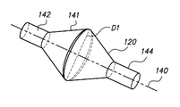
- the anchoring balloon 120 includes a first-end portion 142 (e.g. proximal), a middle-body portion 141 (e.g. expandable) and a second-end portion 144 (e.g. distal), collectively defining a sealed interior of the balloon through which the support structure 150 , elongate member 110 or other type of elongate structure extends.
- the term “support structure” may refer to any device or component to which one or more components may be directly or indirectly coupled, attached or secured.
- the support structure 150 may include a plurality of elongate members (e.g.
- first-end portion 142 of the balloon 120 is secured to a first elongate member of the support structure 150
- second-end portion 144 of the balloon is secured to a second elongate member of the support structure 150
- the first-end portion 142 and second-end portion 144 of the balloon 120 may include respective tubular or other suitable configurations to be coupled to the support structure 150 by adhesive, thermal bonding or the like, interlocking geometries, mechanical fastening, sutures or combinations thereof.
- the anchoring balloon 120 may be made of, or otherwise include polymeric materials, such as silicone, urethane polymer, thermoplastic elastomers rubber, such as santoprene, nylon, and polyethylene terephthalate (PET) and other suitable materials or combinations thereof.
- the anchoring balloon 120 is composed of polyurethane which provides a balloon having superior performance and manufacturing attributes.
- the anchoring balloon 120 material may have a shore durometer range between A90 to A100, and/or a shore durometer range between D30 to D70.
- the anchoring balloon 120 may be manufactured with standard processing equipment to obtain a molded balloon having a wall thickness of approximately between 0.001 inches to 0.003 inches.
- the wall thickness of the anchoring balloon 120 may vary from thicker, in and around the first-end portion 142 and in and around the second-end portion 144 to thinner in and around the a middle-body portion 141 at least.
- the first-end portion 142 may have a wall thickness greater than a wall thickness of the middle-body portion 141 .
- FIG. 3A a double conical or diamond molded configuration is manufactured ( FIG. 3A ).
- FIG. 3E illustrate an embodiment of the molded double conical or diamond configuration of the anchoring balloon 120 , which may have an approximately angle of 30° (A1-4) from an axis 140 (e.g. aggregated 60°), a corresponding inside diameter D 1 of approximately 13 millimeters (0.51 inches) at the center of the balloon 120 , and a length L 1 of approximately 18 millimeters (0.7 inches) at middle-body portion 141 of the balloon 120 .
- A1-4 approximately angle of 30°
- the anchoring balloon 120 can have a variety of shapes in the molded, mounted or inflated configurations, including but not limited to: a double conical, diamond, circular, oval, multi-sided, or irregular shapes, and/or angles that are adapted to resists or avoid cuffing of the balloon 120 when placed in-situ in a body cavity.
- the balloon middle-body portion 141 has a non-tensioned length L 1 ( FIG.
- the balloon middle-body portion 141 may be stretched to a tensioned length that is in a range of about 5% to about 35% greater than the non-tensioned length L 1 , and more preferably to a tensioned length that is in a range of about 8% to about 12% greater than the non-tensioned length L 1 ( FIG. 3B ).
- the anchoring balloon 120 When inflated ( FIG. 3D ), the anchoring balloon 120 may have a diameter D 2 of approximately of 22 millimeters (0.86 inches).
- the molded preformed configuration of the anchoring balloon 120 is stretched, for example, in a longitudinal direction along the axis 140 to form the pre-stretched or stretched-mounted configuration of the balloon 120 , as shown in FIG. 3B .
- the balloon 120 is stretch-mounted to the support structure 150 so as to be in tension relative to the support structure 150 .
- the balloon middle-body portion 141 may be twisted relative to the support structure 150 .
- the balloon 120 is formed in a diamond-like configuration ( FIG. 3A ) that transitions to a substantially spherical configuration ( FIG. 3D ) when the balloon 120 is inflated to a inflation pressure that is at least about ten percent greater than atmospheric pressure external to the balloon 120 , such that the balloon, when inflated to the inflation pressure and anchored in an anatomical body region, resists movement of the support structure 150 relative to the balloon 120 .
- the first and second end portions 142 and 144 of the balloon 120 may be secured to the elongate member 110 or suitable support structure using bonding, brazing, adhesive, thermal bonding or the like, interlocking geometries, mechanical fastening, sutures or combinations thereof.
- the molded configuration of the anchoring balloon 120 is stretched and the stretching of the balloon 120 is preferably in a longitudinal direction along the axis 140 of the molded configuration.
- the molded configuration of the anchoring balloon 120 may be rotated and/or twisted around the axis 140 ; rotation and/or twisting may occur simultaneously or consecutively with the longitudinal stretch of the anchoring balloon 120 . As shown in FIG.
- an inflated configuration of the mounted anchoring balloon of FIG. 3B has a double conical or diamond configuration when the interior of the balloon is inflated to a pressure equal or similar to the atmospheric pressure.
- the anchoring balloon 120 has a substantially spherical configuration when inflated, as shown in FIG. 3D .
- the inflated configurations of the anchoring balloon 120 ( FIGS. 3C-D ) resist or avoid cuffing of the balloon 120 when placed in-situ in a body cavity, further resisting movement of the elongate member 110 relative to the balloon.
- the inflated balloon 120 may have an elliptical or other suitable inflated configuration when the molded anchoring balloon has other shapes including but not limited to: a circular, oval, multi-sided, or irregular shapes.
- FIG. 4 illustrates the anchoring balloon 120 in an unexpanded, pre-stretched or stretched-mounted configuration disposed on the distal portion 114 of the SUI assembly 100 according to one embodiment of the disclosed inventions.
- the elongate member 110 includes at least a lumen 130 that accommodates a hypotube 132 within the cooling balloon 122 and energy delivery member 118 , and provides a fluid path for inflation and deflation of the anchoring balloon 120 .
- the structure of the assembly 100 and elongate member 110 allows fluid communication between a fluid port 134 ( FIG. 1 ), the lumen 130 ( FIG. 4 ) and the anchoring balloon 120 .
- a seal 136 FIG.
- the fluid port 134 is included at the fluid port 134 to provide a fluid seal and maintain inflation or deflation of the anchoring balloon 120 .
- the fluid seal may be positioned at any suitable location between the fluid port 134 and the anchoring balloon 120 .
- An inflation source (not shown) is fluidly connected to the lumen 130 to deliver and/or withdraw fluid from the anchoring balloon 120 . From the proximal opening of the lumen 130 at the fluid port 134 , the introduced fluid travels in the lumen 130 into the interior of the balloon 120 to inflate the balloon thereof.
- the distal portion 114 of the assembly 100 may include a support structure 150 where the stretched configuration of the anchoring balloon 120 is mounted.
- the support structure 150 may be composed of rigid, semi-rigid and/or compliant materials and/or alloys, such as, acrylonitrile butadiene styrene (ABS), or combination thereof.
- the support structure 150 includes a first location 152 (e.g. proximal portion) and a second location 154 (e.g. distal portion).
- the first location 152 of the support structure 150 secures the first-end portion 142 of the anchoring balloon 120
- the second location 154 of the support structure secures the second-end portion 144 of the anchoring balloon 120
- bonding, brazing, adhesive, thermal bonding or the like interlocking geometries, mechanical fastening, sutures or combinations thereof.
- the first-end portion 142 of the balloon is secured to the support structure 150 at the first location 152
- the second-end portion 144 is secured to the support structure 150 at the second location 154 distal to the first location 152 , and to the middle-body portion 141 .
- the first location 152 of the support structure 150 may accommodate a portion of the hypotube 132 to provide fluid communication of the lumen 130 to the anchoring balloon 120 .
- the second location 154 of the support structure 150 may include a non-traumatic, semi-spherical or rounded tip end 156 .
- the anchoring balloon 120 is stretch-mounted to the support structure 150 so as to be in tension relative to the support structure 150 .
- the balloon 120 is formed in a diamond-like configuration ( FIG. 3A ) that transitions to a substantially spherical configuration ( FIG.
- the anchoring balloon 120 may be manufactured by forming an inflatable balloon 120 having a first-end portion 142 , a second-end portion 144 , and a middle-body portion 141 , the middle-body portion 141 having a first end integrally formed with or otherwise bonded to the first-end portion, and a second end integrally formed with or otherwise bonded to the second-end portion, the first-end portion having a wall thickness greater than a wall thickness of the middle-body portion 141 . Then, securing the first-end portion 142 to the first location 152 on an elongate support structure 150 (step 300 ).
- the balloon 120 is formed in a diamond-like configuration that transitions to a substantially spherical configuration when the balloon 120 is inflated to an inflation pressure that is at least about ten percent greater than atmospheric pressure external to the balloon 120 .
- the middle-body portion 141 of the balloon 120 is twisted (step 304 ) relative to the support structure 150 prior to securing the second-end portion 144 of the balloon 120 to the support structure 150 .
- the support structure 150 may include a plurality of elongate members, where the first-end portion 142 of the balloon 120 is secured to a first elongate member of the support structure 150 , and the second-end portion 144 of the balloon is secured to a second elongate member of the support structure 150 . Further, the first-end portion 142 and second-end portion 144 of the balloon 120 are each secured to the support structure 150 by one of adhesive bonding, thermal bonding, interlocking geometries, and mechanical fastening.
- the mounted balloon 120 is manufactured by securing one end portion of the balloon 120 (either the first-end portion 142 or the second-end portion 144 portion) to the support structure 150 (step 300 ), then balloon 120 is stretched (step 302 ), and then, the unsecured end portion of the balloon 120 is also secured to support structure 150 (step 306 ).
- the anchoring balloon 120 may be rotated and/or twisted around the axis 140 (step 304 ) simultaneously or consecutively with the longitudinal stretching of the balloon 120 . After stretching, rotation and/or twisting of anchoring balloon 120 , the unsecured second end portion of the balloon 120 is mounted and secured to the support structure 150 (step 306 ).
- the pre-stretched or stretched-mounted configuration of the balloon 120 is formed, as shown in FIG. 3B .
- the balloon 120 may be deflated, as shown in FIG. 3B , and/or inflated, as shown in FIGS. 3C-D (step 308 ).
- the anchoring balloon 120 may be manufactured by first stretching the molded configuration of the anchoring balloon 120 (step 302 ) along the axis 140 , before mounting the anchoring balloon 120 to the support structure 150 .
- the anchoring balloon 120 may be rotated and/or twisted around the axis 140 (step 304 ) simultaneously or consecutively with the longitudinal stretching of the balloon 120 .
- one end portion of the balloon 120 i.e. either the first-end portion 142 or the second-end portion 144 portion
- the second end portion of the balloon 120 is also mounted and secured to the elongate member 110 or support structure 150 (step 306 ).
- FIG. 7 illustrates experimental data conducted on the anchoring balloon 120 ( FIGS. 3A-4 and 6A ) when being placed through the urethra 200 into the bladder 220 (as shown in FIG. 2 ). The results are shown in comparison with a Silicon Foley Catheter 12 French (Universa® by Cook Medical).
- the anchoring balloon 120 constructed according to the embodiments of the disclosed invention is configured to provide a substantially immediate and sharp rise in tactile feedback to the end user or physician, particularly under low force or load conditions (e.g. represented as the slope of force over displacement in FIG. 7 ) to detect location of the anchoring balloon 120 within the bladder 220 .
- the slope column of FIG. 7 represents the amount of force (e.g. applied by physician/user to the balloon when pulling or withdrawing the medical assembly in-situ), over the displacement (e.g. distance to balloon moves over that force range).
Abstract
Description
Claims (18)
Priority Applications (6)
| Application Number | Priority Date | Filing Date | Title |
|---|---|---|---|
| US14/139,609 US9480824B2 (en) | 2013-12-23 | 2013-12-23 | Cuff-resistant anchoring balloon for medical device |
| PCT/US2014/063885 WO2015099886A1 (en) | 2013-12-23 | 2014-11-04 | Cuff-resistant anchoring balloon for medical device |
| EP14806761.4A EP3086832B1 (en) | 2013-12-23 | 2014-11-04 | Cuff-resistant anchoring balloon for medical device |
| ES14806761T ES2768655T3 (en) | 2013-12-23 | 2014-11-04 | Cuff-resistant fixation balloon for medical device |
| AU2014370359A AU2014370359B2 (en) | 2013-12-23 | 2014-11-04 | Cuff-resistant anchoring balloon for medical device |
| US15/280,475 US10315015B2 (en) | 2013-12-23 | 2016-09-29 | Cuff-resistant anchoring balloon for medical device |
Applications Claiming Priority (1)
| Application Number | Priority Date | Filing Date | Title |
|---|---|---|---|
| US14/139,609 US9480824B2 (en) | 2013-12-23 | 2013-12-23 | Cuff-resistant anchoring balloon for medical device |
Related Child Applications (1)
| Application Number | Title | Priority Date | Filing Date |
|---|---|---|---|
| US15/280,475 Continuation US10315015B2 (en) | 2013-12-23 | 2016-09-29 | Cuff-resistant anchoring balloon for medical device |
Publications (2)
| Publication Number | Publication Date |
|---|---|
| US20150174380A1 US20150174380A1 (en) | 2015-06-25 |
| US9480824B2 true US9480824B2 (en) | 2016-11-01 |
Family
ID=52007265
Family Applications (2)
| Application Number | Title | Priority Date | Filing Date |
|---|---|---|---|
| US14/139,609 Active 2034-11-02 US9480824B2 (en) | 2013-12-23 | 2013-12-23 | Cuff-resistant anchoring balloon for medical device |
| US15/280,475 Active 2034-09-23 US10315015B2 (en) | 2013-12-23 | 2016-09-29 | Cuff-resistant anchoring balloon for medical device |
Family Applications After (1)
| Application Number | Title | Priority Date | Filing Date |
|---|---|---|---|
| US15/280,475 Active 2034-09-23 US10315015B2 (en) | 2013-12-23 | 2016-09-29 | Cuff-resistant anchoring balloon for medical device |
Country Status (5)
| Country | Link |
|---|---|
| US (2) | US9480824B2 (en) |
| EP (1) | EP3086832B1 (en) |
| AU (1) | AU2014370359B2 (en) |
| ES (1) | ES2768655T3 (en) |
| WO (1) | WO2015099886A1 (en) |
Cited By (1)
| Publication number | Priority date | Publication date | Assignee | Title |
|---|---|---|---|---|
| US11229466B2 (en) | 2018-01-12 | 2022-01-25 | KyphEZE, Inc. | Bone expansion systems and methods |
Families Citing this family (2)
| Publication number | Priority date | Publication date | Assignee | Title |
|---|---|---|---|---|
| CN113663206A (en) * | 2021-08-10 | 2021-11-19 | 温州市人民医院 | Urethral drainage tube with negative pressure suction ball |
| CN113802553A (en) * | 2021-09-18 | 2021-12-17 | 中国华冶科工集团有限公司 | Test anchor rod construction device and anti-floating test method |
Citations (17)
| Publication number | Priority date | Publication date | Assignee | Title |
|---|---|---|---|---|
| WO1989011306A1 (en) | 1988-05-27 | 1989-11-30 | Terje Eide | A balloon catheter and a method for producing the same |
| EP0421031B1 (en) | 1989-10-03 | 1993-06-09 | American Medical Systems, Inc. | Prostate balloon dilator |
| US5707357A (en) | 1995-02-23 | 1998-01-13 | C V Dynamics, Inc. | Balloon catheter having palpitatable discharge valve and retention collar |
| WO1998039044A2 (en) | 1997-03-06 | 1998-09-11 | Percusurge, Inc. | Balloon catheter and method of manufacture |
| US5827225A (en) | 1994-09-26 | 1998-10-27 | Medtronic, Inc. | Catheter flexible distal tip |
| US5853389A (en) * | 1996-03-07 | 1998-12-29 | Cordis Corporation | Balloon catheter and method for manufacturing |
| US20030009079A1 (en) | 2001-07-06 | 2003-01-09 | Opticon Medical, Inc. | Urinary flow control valve |
| US6796972B1 (en) | 2000-07-14 | 2004-09-28 | Edwards Lifesciences Llc | Catheter anchoring balloon structure with irrigation |
| US20040199086A1 (en) | 2003-04-03 | 2004-10-07 | Crisp William E. | Urinary tract catheter |
| US20050288630A1 (en) * | 2004-01-22 | 2005-12-29 | Conway Anthony J | Cuff resistant foley catheter |
| WO2007005239A1 (en) | 2005-06-29 | 2007-01-11 | Rochester Medical Corporation | Method of making a catheter device |
| US8070717B2 (en) | 2001-11-27 | 2011-12-06 | Kimberly-Clark Worldwide, Inc. | Bladder catheter |
| US20120109179A1 (en) * | 2009-04-15 | 2012-05-03 | Trinity College, Dublin University | Intravasculature Devices and Balloons for Use Therewith |
| US20120239046A1 (en) * | 2009-03-17 | 2012-09-20 | William Kaiser | Method and apparatus for distracting a joint |
| WO2013040522A2 (en) | 2011-09-16 | 2013-03-21 | W.L. Gore & Associates, Inc. | Controllable inflation profile balloon cover apparatus and methods |
| US8454648B1 (en) | 2009-03-25 | 2013-06-04 | Radiadyne Llc | Locking device for a prostate immobilizer |
| US20140074020A1 (en) * | 2012-09-11 | 2014-03-13 | Kenneth L. Wantink | Soft tip balloon catheter |
-
2013
- 2013-12-23 US US14/139,609 patent/US9480824B2/en active Active
-
2014
- 2014-11-04 EP EP14806761.4A patent/EP3086832B1/en active Active
- 2014-11-04 ES ES14806761T patent/ES2768655T3/en active Active
- 2014-11-04 AU AU2014370359A patent/AU2014370359B2/en active Active
- 2014-11-04 WO PCT/US2014/063885 patent/WO2015099886A1/en active Application Filing
-
2016
- 2016-09-29 US US15/280,475 patent/US10315015B2/en active Active
Patent Citations (17)
| Publication number | Priority date | Publication date | Assignee | Title |
|---|---|---|---|---|
| WO1989011306A1 (en) | 1988-05-27 | 1989-11-30 | Terje Eide | A balloon catheter and a method for producing the same |
| EP0421031B1 (en) | 1989-10-03 | 1993-06-09 | American Medical Systems, Inc. | Prostate balloon dilator |
| US5827225A (en) | 1994-09-26 | 1998-10-27 | Medtronic, Inc. | Catheter flexible distal tip |
| US5707357A (en) | 1995-02-23 | 1998-01-13 | C V Dynamics, Inc. | Balloon catheter having palpitatable discharge valve and retention collar |
| US5853389A (en) * | 1996-03-07 | 1998-12-29 | Cordis Corporation | Balloon catheter and method for manufacturing |
| WO1998039044A2 (en) | 1997-03-06 | 1998-09-11 | Percusurge, Inc. | Balloon catheter and method of manufacture |
| US6796972B1 (en) | 2000-07-14 | 2004-09-28 | Edwards Lifesciences Llc | Catheter anchoring balloon structure with irrigation |
| US20030009079A1 (en) | 2001-07-06 | 2003-01-09 | Opticon Medical, Inc. | Urinary flow control valve |
| US8070717B2 (en) | 2001-11-27 | 2011-12-06 | Kimberly-Clark Worldwide, Inc. | Bladder catheter |
| US20040199086A1 (en) | 2003-04-03 | 2004-10-07 | Crisp William E. | Urinary tract catheter |
| US20050288630A1 (en) * | 2004-01-22 | 2005-12-29 | Conway Anthony J | Cuff resistant foley catheter |
| WO2007005239A1 (en) | 2005-06-29 | 2007-01-11 | Rochester Medical Corporation | Method of making a catheter device |
| US20120239046A1 (en) * | 2009-03-17 | 2012-09-20 | William Kaiser | Method and apparatus for distracting a joint |
| US8454648B1 (en) | 2009-03-25 | 2013-06-04 | Radiadyne Llc | Locking device for a prostate immobilizer |
| US20120109179A1 (en) * | 2009-04-15 | 2012-05-03 | Trinity College, Dublin University | Intravasculature Devices and Balloons for Use Therewith |
| WO2013040522A2 (en) | 2011-09-16 | 2013-03-21 | W.L. Gore & Associates, Inc. | Controllable inflation profile balloon cover apparatus and methods |
| US20140074020A1 (en) * | 2012-09-11 | 2014-03-13 | Kenneth L. Wantink | Soft tip balloon catheter |
Non-Patent Citations (1)
| Title |
|---|
| PCT International Search Report and Written Opinion for International Application No. PCT/US2014/063885, Applicant Hologic, Inc., forms PCT/ISA/210, 220, and 237, dated Mar. 13, 2015 (13 pages). |
Cited By (2)
| Publication number | Priority date | Publication date | Assignee | Title |
|---|---|---|---|---|
| US11883083B2 (en) | 2015-07-15 | 2024-01-30 | KyphEZE, Inc. | Bone expansion systems and methods |
| US11229466B2 (en) | 2018-01-12 | 2022-01-25 | KyphEZE, Inc. | Bone expansion systems and methods |
Also Published As
| Publication number | Publication date |
|---|---|
| US20170014602A1 (en) | 2017-01-19 |
| US20150174380A1 (en) | 2015-06-25 |
| ES2768655T3 (en) | 2020-06-23 |
| AU2014370359B2 (en) | 2017-12-14 |
| AU2014370359A1 (en) | 2016-07-07 |
| US10315015B2 (en) | 2019-06-11 |
| WO2015099886A1 (en) | 2015-07-02 |
| EP3086832B1 (en) | 2020-01-15 |
| EP3086832A1 (en) | 2016-11-02 |
Similar Documents
| Publication | Publication Date | Title |
|---|---|---|
| US11786706B2 (en) | Micro-needle bladder balloon | |
| US9028443B2 (en) | Weeping balloon catheter with drug delivery balloon in fluid communication with combination lumen | |
| US10315015B2 (en) | Cuff-resistant anchoring balloon for medical device | |
| US10173039B2 (en) | Balloon catheter | |
| US9687331B2 (en) | Locking device | |
| US20040049170A1 (en) | Balloon-free urinary catheter | |
| US20170100565A1 (en) | Methods and systems for treatment of a bladder | |
| US8518020B2 (en) | Safety urinary catheter | |
| AU2006255043B2 (en) | Injection guidance system and method | |
| US20050049575A1 (en) | Medical device | |
| US20140350330A1 (en) | Expansion instrument | |
| JP6301909B2 (en) | Stretch valve balloon catheter and method for producing and using the same | |
| US20220305242A1 (en) | Balloon dilation device | |
| KR20210066393A (en) | Medical catheter |
Legal Events
| Date | Code | Title | Description |
|---|---|---|---|
| AS | Assignment |
Owner name: HOLOGIC, INC., MASSACHUSETTS Free format text: ASSIGNMENT OF ASSIGNORS INTEREST;ASSIGNORS:KAISER, CHRISTOPHER CHARLES;SCHENCK, JESSICA TINA;REEL/FRAME:031953/0375 Effective date: 20140108 |
|
| AS | Assignment |
Owner name: GOLDMAN SACHS BANK USA, NEW JERSEY Free format text: SECURITY AGREEMENT;ASSIGNORS:HOLOGIC, INC.;BIOLUCENT, LLC;CYTYC CORPORATION;AND OTHERS;REEL/FRAME:032059/0467 Effective date: 20140107 |
|
| AS | Assignment |
Owner name: CYTYC CORPORATION, MASSACHUSETTS Free format text: SECURITY INTEREST RELEASE REEL/FRAME 032059 0467;ASSIGNOR:GOLDMAN SACHS BANK USA, AS COLLATERAL AGENT;REEL/FRAME:036126/0813 Effective date: 20150529 Owner name: THIRD WAVE TECHNOLOGIES, INC., MASSACHUSETTS Free format text: SECURITY INTEREST RELEASE REEL/FRAME 032059 0467;ASSIGNOR:GOLDMAN SACHS BANK USA, AS COLLATERAL AGENT;REEL/FRAME:036126/0813 Effective date: 20150529 Owner name: SUROS SURGICAL SYSTEMS, INC., MASSACHUSETTS Free format text: SECURITY INTEREST RELEASE REEL/FRAME 032059 0467;ASSIGNOR:GOLDMAN SACHS BANK USA, AS COLLATERAL AGENT;REEL/FRAME:036126/0813 Effective date: 20150529 Owner name: DIRECT RADIOGRAPHY CORP., MASSACHUSETTS Free format text: SECURITY INTEREST RELEASE REEL/FRAME 032059 0467;ASSIGNOR:GOLDMAN SACHS BANK USA, AS COLLATERAL AGENT;REEL/FRAME:036126/0813 Effective date: 20150529 Owner name: CYTYC SURGICAL PRODUCTS, LIMITED PARTNERSHIP, MASS Free format text: SECURITY INTEREST RELEASE REEL/FRAME 032059 0467;ASSIGNOR:GOLDMAN SACHS BANK USA, AS COLLATERAL AGENT;REEL/FRAME:036126/0813 Effective date: 20150529 Owner name: BIOLUCENT, LLC, MASSACHUSETTS Free format text: SECURITY INTEREST RELEASE REEL/FRAME 032059 0467;ASSIGNOR:GOLDMAN SACHS BANK USA, AS COLLATERAL AGENT;REEL/FRAME:036126/0813 Effective date: 20150529 Owner name: GEN-PROBE INCORPORATED, MASSACHUSETTS Free format text: SECURITY INTEREST RELEASE REEL/FRAME 032059 0467;ASSIGNOR:GOLDMAN SACHS BANK USA, AS COLLATERAL AGENT;REEL/FRAME:036126/0813 Effective date: 20150529 Owner name: HOLOGIC, INC., MASSACHUSETTS Free format text: SECURITY INTEREST RELEASE REEL/FRAME 032059 0467;ASSIGNOR:GOLDMAN SACHS BANK USA, AS COLLATERAL AGENT;REEL/FRAME:036126/0813 Effective date: 20150529 |
|
| AS | Assignment |
Owner name: BANK OF AMERICA, N.A., AS COLLATERAL AGENT, NORTH CAROLINA Free format text: SECURITY AGREEMENT;ASSIGNORS:HOLOGIC, INC.;BIOLUCENT, LLC;CYTYC CORPORATION;AND OTHERS;REEL/FRAME:036307/0199 Effective date: 20150529 Owner name: BANK OF AMERICA, N.A., AS COLLATERAL AGENT, NORTH Free format text: SECURITY AGREEMENT;ASSIGNORS:HOLOGIC, INC.;BIOLUCENT, LLC;CYTYC CORPORATION;AND OTHERS;REEL/FRAME:036307/0199 Effective date: 20150529 |
|
| STCF | Information on status: patent grant |
Free format text: PATENTED CASE |
|
| MAFP | Maintenance fee payment |
Free format text: PAYMENT OF MAINTENANCE FEE, 4TH YEAR, LARGE ENTITY (ORIGINAL EVENT CODE: M1551); ENTITY STATUS OF PATENT OWNER: LARGE ENTITY Year of fee payment: 4 |