US9498560B2 - Interspinous spacer implant - Google Patents
Interspinous spacer implant Download PDFInfo
- Publication number
- US9498560B2 US9498560B2 US13/411,478 US201213411478A US9498560B2 US 9498560 B2 US9498560 B2 US 9498560B2 US 201213411478 A US201213411478 A US 201213411478A US 9498560 B2 US9498560 B2 US 9498560B2
- Authority
- US
- United States
- Prior art keywords
- interspinous spacer
- interspinous
- spacer
- prongs
- openings
- Prior art date
- Legal status (The legal status is an assumption and is not a legal conclusion. Google has not performed a legal analysis and makes no representation as to the accuracy of the status listed.)
- Active, expires
Links
Images


Classifications
-
- A—HUMAN NECESSITIES
- A61—MEDICAL OR VETERINARY SCIENCE; HYGIENE
- A61L—METHODS OR APPARATUS FOR STERILISING MATERIALS OR OBJECTS IN GENERAL; DISINFECTION, STERILISATION OR DEODORISATION OF AIR; CHEMICAL ASPECTS OF BANDAGES, DRESSINGS, ABSORBENT PADS OR SURGICAL ARTICLES; MATERIALS FOR BANDAGES, DRESSINGS, ABSORBENT PADS OR SURGICAL ARTICLES
- A61L27/00—Materials for grafts or prostheses or for coating grafts or prostheses
- A61L27/40—Composite materials, i.e. containing one material dispersed in a matrix of the same or different material
- A61L27/42—Composite materials, i.e. containing one material dispersed in a matrix of the same or different material having an inorganic matrix
- A61L27/425—Composite materials, i.e. containing one material dispersed in a matrix of the same or different material having an inorganic matrix of phosphorus containing material, e.g. apatite
-
- A—HUMAN NECESSITIES
- A61—MEDICAL OR VETERINARY SCIENCE; HYGIENE
- A61B—DIAGNOSIS; SURGERY; IDENTIFICATION
- A61B17/00—Surgical instruments, devices or methods, e.g. tourniquets
- A61B17/16—Bone cutting, breaking or removal means other than saws, e.g. Osteoclasts; Drills or chisels for bones; Trepans
- A61B17/1662—Bone cutting, breaking or removal means other than saws, e.g. Osteoclasts; Drills or chisels for bones; Trepans for particular parts of the body
- A61B17/1671—Bone cutting, breaking or removal means other than saws, e.g. Osteoclasts; Drills or chisels for bones; Trepans for particular parts of the body for the spine
-
- A—HUMAN NECESSITIES
- A61—MEDICAL OR VETERINARY SCIENCE; HYGIENE
- A61B—DIAGNOSIS; SURGERY; IDENTIFICATION
- A61B17/00—Surgical instruments, devices or methods, e.g. tourniquets
- A61B17/56—Surgical instruments or methods for treatment of bones or joints; Devices specially adapted therefor
- A61B17/58—Surgical instruments or methods for treatment of bones or joints; Devices specially adapted therefor for osteosynthesis, e.g. bone plates, screws, setting implements or the like
- A61B17/68—Internal fixation devices, including fasteners and spinal fixators, even if a part thereof projects from the skin
- A61B17/70—Spinal positioners or stabilisers ; Bone stabilisers comprising fluid filler in an implant
- A61B17/7062—Devices acting on, attached to, or simulating the effect of, vertebral processes, vertebral facets or ribs ; Tools for such devices
- A61B17/7065—Devices with changeable shape, e.g. collapsible or having retractable arms to aid implantation; Tools therefor
-
- A—HUMAN NECESSITIES
- A61—MEDICAL OR VETERINARY SCIENCE; HYGIENE
- A61B—DIAGNOSIS; SURGERY; IDENTIFICATION
- A61B17/00—Surgical instruments, devices or methods, e.g. tourniquets
- A61B17/56—Surgical instruments or methods for treatment of bones or joints; Devices specially adapted therefor
- A61B17/58—Surgical instruments or methods for treatment of bones or joints; Devices specially adapted therefor for osteosynthesis, e.g. bone plates, screws, setting implements or the like
- A61B17/68—Internal fixation devices, including fasteners and spinal fixators, even if a part thereof projects from the skin
- A61B17/70—Spinal positioners or stabilisers ; Bone stabilisers comprising fluid filler in an implant
- A61B17/7062—Devices acting on, attached to, or simulating the effect of, vertebral processes, vertebral facets or ribs ; Tools for such devices
- A61B17/7067—Devices bearing against one or more spinous processes and also attached to another part of the spine; Tools therefor
-
- A—HUMAN NECESSITIES
- A61—MEDICAL OR VETERINARY SCIENCE; HYGIENE
- A61B—DIAGNOSIS; SURGERY; IDENTIFICATION
- A61B17/00—Surgical instruments, devices or methods, e.g. tourniquets
- A61B17/56—Surgical instruments or methods for treatment of bones or joints; Devices specially adapted therefor
- A61B17/58—Surgical instruments or methods for treatment of bones or joints; Devices specially adapted therefor for osteosynthesis, e.g. bone plates, screws, setting implements or the like
- A61B17/68—Internal fixation devices, including fasteners and spinal fixators, even if a part thereof projects from the skin
- A61B17/70—Spinal positioners or stabilisers ; Bone stabilisers comprising fluid filler in an implant
- A61B17/7062—Devices acting on, attached to, or simulating the effect of, vertebral processes, vertebral facets or ribs ; Tools for such devices
- A61B17/7068—Devices comprising separate rigid parts, assembled in situ, to bear on each side of spinous processes; Tools therefor
-
- A—HUMAN NECESSITIES
- A61—MEDICAL OR VETERINARY SCIENCE; HYGIENE
- A61L—METHODS OR APPARATUS FOR STERILISING MATERIALS OR OBJECTS IN GENERAL; DISINFECTION, STERILISATION OR DEODORISATION OF AIR; CHEMICAL ASPECTS OF BANDAGES, DRESSINGS, ABSORBENT PADS OR SURGICAL ARTICLES; MATERIALS FOR BANDAGES, DRESSINGS, ABSORBENT PADS OR SURGICAL ARTICLES
- A61L27/00—Materials for grafts or prostheses or for coating grafts or prostheses
- A61L27/02—Inorganic materials
- A61L27/04—Metals or alloys
- A61L27/042—Iron or iron alloys
-
- A—HUMAN NECESSITIES
- A61—MEDICAL OR VETERINARY SCIENCE; HYGIENE
- A61L—METHODS OR APPARATUS FOR STERILISING MATERIALS OR OBJECTS IN GENERAL; DISINFECTION, STERILISATION OR DEODORISATION OF AIR; CHEMICAL ASPECTS OF BANDAGES, DRESSINGS, ABSORBENT PADS OR SURGICAL ARTICLES; MATERIALS FOR BANDAGES, DRESSINGS, ABSORBENT PADS OR SURGICAL ARTICLES
- A61L27/00—Materials for grafts or prostheses or for coating grafts or prostheses
- A61L27/02—Inorganic materials
- A61L27/04—Metals or alloys
- A61L27/06—Titanium or titanium alloys
-
- A—HUMAN NECESSITIES
- A61—MEDICAL OR VETERINARY SCIENCE; HYGIENE
- A61B—DIAGNOSIS; SURGERY; IDENTIFICATION
- A61B17/00—Surgical instruments, devices or methods, e.g. tourniquets
- A61B17/16—Bone cutting, breaking or removal means other than saws, e.g. Osteoclasts; Drills or chisels for bones; Trepans
- A61B17/1659—Surgical rasps, files, planes, or scrapers
-
- A—HUMAN NECESSITIES
- A61—MEDICAL OR VETERINARY SCIENCE; HYGIENE
- A61B—DIAGNOSIS; SURGERY; IDENTIFICATION
- A61B17/00—Surgical instruments, devices or methods, e.g. tourniquets
- A61B17/32—Surgical cutting instruments
- A61B17/3205—Excision instruments
- A61B17/32053—Punch like cutting instruments, e.g. using a cylindrical or oval knife
-
- A—HUMAN NECESSITIES
- A61—MEDICAL OR VETERINARY SCIENCE; HYGIENE
- A61B—DIAGNOSIS; SURGERY; IDENTIFICATION
- A61B17/00—Surgical instruments, devices or methods, e.g. tourniquets
- A61B17/02—Surgical instruments, devices or methods, e.g. tourniquets for holding wounds open; Tractors
- A61B17/025—Joint distractors
- A61B2017/0256—Joint distractors for the spine
-
- A—HUMAN NECESSITIES
- A61—MEDICAL OR VETERINARY SCIENCE; HYGIENE
- A61B—DIAGNOSIS; SURGERY; IDENTIFICATION
- A61B90/00—Instruments, implements or accessories specially adapted for surgery or diagnosis and not covered by any of the groups A61B1/00 - A61B50/00, e.g. for luxation treatment or for protecting wound edges
- A61B90/06—Measuring instruments not otherwise provided for
- A61B2090/061—Measuring instruments not otherwise provided for for measuring dimensions, e.g. length
-
- A—HUMAN NECESSITIES
- A61—MEDICAL OR VETERINARY SCIENCE; HYGIENE
- A61F—FILTERS IMPLANTABLE INTO BLOOD VESSELS; PROSTHESES; DEVICES PROVIDING PATENCY TO, OR PREVENTING COLLAPSING OF, TUBULAR STRUCTURES OF THE BODY, e.g. STENTS; ORTHOPAEDIC, NURSING OR CONTRACEPTIVE DEVICES; FOMENTATION; TREATMENT OR PROTECTION OF EYES OR EARS; BANDAGES, DRESSINGS OR ABSORBENT PADS; FIRST-AID KITS
- A61F2/00—Filters implantable into blood vessels; Prostheses, i.e. artificial substitutes or replacements for parts of the body; Appliances for connecting them with the body; Devices providing patency to, or preventing collapsing of, tubular structures of the body, e.g. stents
- A61F2/02—Prostheses implantable into the body
- A61F2/30—Joints
- A61F2/3094—Designing or manufacturing processes
- A61F2/30965—Reinforcing the prosthesis by embedding particles or fibres during moulding or dipping
-
- A—HUMAN NECESSITIES
- A61—MEDICAL OR VETERINARY SCIENCE; HYGIENE
- A61F—FILTERS IMPLANTABLE INTO BLOOD VESSELS; PROSTHESES; DEVICES PROVIDING PATENCY TO, OR PREVENTING COLLAPSING OF, TUBULAR STRUCTURES OF THE BODY, e.g. STENTS; ORTHOPAEDIC, NURSING OR CONTRACEPTIVE DEVICES; FOMENTATION; TREATMENT OR PROTECTION OF EYES OR EARS; BANDAGES, DRESSINGS OR ABSORBENT PADS; FIRST-AID KITS
- A61F2/00—Filters implantable into blood vessels; Prostheses, i.e. artificial substitutes or replacements for parts of the body; Appliances for connecting them with the body; Devices providing patency to, or preventing collapsing of, tubular structures of the body, e.g. stents
- A61F2/02—Prostheses implantable into the body
- A61F2/30—Joints
- A61F2/46—Special tools or methods for implanting or extracting artificial joints, accessories, bone grafts or substitutes, or particular adaptations therefor
- A61F2/4603—Special tools or methods for implanting or extracting artificial joints, accessories, bone grafts or substitutes, or particular adaptations therefor for insertion or extraction of endoprosthetic joints or of accessories thereof
- A61F2/4611—Special tools or methods for implanting or extracting artificial joints, accessories, bone grafts or substitutes, or particular adaptations therefor for insertion or extraction of endoprosthetic joints or of accessories thereof of spinal prostheses
-
- A—HUMAN NECESSITIES
- A61—MEDICAL OR VETERINARY SCIENCE; HYGIENE
- A61F—FILTERS IMPLANTABLE INTO BLOOD VESSELS; PROSTHESES; DEVICES PROVIDING PATENCY TO, OR PREVENTING COLLAPSING OF, TUBULAR STRUCTURES OF THE BODY, e.g. STENTS; ORTHOPAEDIC, NURSING OR CONTRACEPTIVE DEVICES; FOMENTATION; TREATMENT OR PROTECTION OF EYES OR EARS; BANDAGES, DRESSINGS OR ABSORBENT PADS; FIRST-AID KITS
- A61F2/00—Filters implantable into blood vessels; Prostheses, i.e. artificial substitutes or replacements for parts of the body; Appliances for connecting them with the body; Devices providing patency to, or preventing collapsing of, tubular structures of the body, e.g. stents
- A61F2/02—Prostheses implantable into the body
- A61F2/28—Bones
- A61F2002/2817—Bone stimulation by chemical reactions or by osteogenic or biological products for enhancing ossification, e.g. by bone morphogenetic or morphogenic proteins [BMP] or by transforming growth factors [TGF]
-
- A—HUMAN NECESSITIES
- A61—MEDICAL OR VETERINARY SCIENCE; HYGIENE
- A61F—FILTERS IMPLANTABLE INTO BLOOD VESSELS; PROSTHESES; DEVICES PROVIDING PATENCY TO, OR PREVENTING COLLAPSING OF, TUBULAR STRUCTURES OF THE BODY, e.g. STENTS; ORTHOPAEDIC, NURSING OR CONTRACEPTIVE DEVICES; FOMENTATION; TREATMENT OR PROTECTION OF EYES OR EARS; BANDAGES, DRESSINGS OR ABSORBENT PADS; FIRST-AID KITS
- A61F2/00—Filters implantable into blood vessels; Prostheses, i.e. artificial substitutes or replacements for parts of the body; Appliances for connecting them with the body; Devices providing patency to, or preventing collapsing of, tubular structures of the body, e.g. stents
- A61F2/02—Prostheses implantable into the body
- A61F2/28—Bones
- A61F2002/2835—Bone graft implants for filling a bony defect or an endoprosthesis cavity, e.g. by synthetic material or biological material
-
- A—HUMAN NECESSITIES
- A61—MEDICAL OR VETERINARY SCIENCE; HYGIENE
- A61F—FILTERS IMPLANTABLE INTO BLOOD VESSELS; PROSTHESES; DEVICES PROVIDING PATENCY TO, OR PREVENTING COLLAPSING OF, TUBULAR STRUCTURES OF THE BODY, e.g. STENTS; ORTHOPAEDIC, NURSING OR CONTRACEPTIVE DEVICES; FOMENTATION; TREATMENT OR PROTECTION OF EYES OR EARS; BANDAGES, DRESSINGS OR ABSORBENT PADS; FIRST-AID KITS
- A61F2/00—Filters implantable into blood vessels; Prostheses, i.e. artificial substitutes or replacements for parts of the body; Appliances for connecting them with the body; Devices providing patency to, or preventing collapsing of, tubular structures of the body, e.g. stents
- A61F2/02—Prostheses implantable into the body
- A61F2/30—Joints
- A61F2002/30001—Additional features of subject-matter classified in A61F2/28, A61F2/30 and subgroups thereof
- A61F2002/30316—The prosthesis having different structural features at different locations within the same prosthesis; Connections between prosthetic parts; Special structural features of bone or joint prostheses not otherwise provided for
- A61F2002/30535—Special structural features of bone or joint prostheses not otherwise provided for
- A61F2002/30593—Special structural features of bone or joint prostheses not otherwise provided for hollow
-
- A—HUMAN NECESSITIES
- A61—MEDICAL OR VETERINARY SCIENCE; HYGIENE
- A61F—FILTERS IMPLANTABLE INTO BLOOD VESSELS; PROSTHESES; DEVICES PROVIDING PATENCY TO, OR PREVENTING COLLAPSING OF, TUBULAR STRUCTURES OF THE BODY, e.g. STENTS; ORTHOPAEDIC, NURSING OR CONTRACEPTIVE DEVICES; FOMENTATION; TREATMENT OR PROTECTION OF EYES OR EARS; BANDAGES, DRESSINGS OR ABSORBENT PADS; FIRST-AID KITS
- A61F2/00—Filters implantable into blood vessels; Prostheses, i.e. artificial substitutes or replacements for parts of the body; Appliances for connecting them with the body; Devices providing patency to, or preventing collapsing of, tubular structures of the body, e.g. stents
- A61F2/02—Prostheses implantable into the body
- A61F2/30—Joints
- A61F2/30767—Special external or bone-contacting surface, e.g. coating for improving bone ingrowth
- A61F2/30771—Special external or bone-contacting surface, e.g. coating for improving bone ingrowth applied in original prostheses, e.g. holes or grooves
- A61F2002/30772—Apertures or holes, e.g. of circular cross section
- A61F2002/30777—Oblong apertures
-
- A—HUMAN NECESSITIES
- A61—MEDICAL OR VETERINARY SCIENCE; HYGIENE
- A61F—FILTERS IMPLANTABLE INTO BLOOD VESSELS; PROSTHESES; DEVICES PROVIDING PATENCY TO, OR PREVENTING COLLAPSING OF, TUBULAR STRUCTURES OF THE BODY, e.g. STENTS; ORTHOPAEDIC, NURSING OR CONTRACEPTIVE DEVICES; FOMENTATION; TREATMENT OR PROTECTION OF EYES OR EARS; BANDAGES, DRESSINGS OR ABSORBENT PADS; FIRST-AID KITS
- A61F2/00—Filters implantable into blood vessels; Prostheses, i.e. artificial substitutes or replacements for parts of the body; Appliances for connecting them with the body; Devices providing patency to, or preventing collapsing of, tubular structures of the body, e.g. stents
- A61F2/02—Prostheses implantable into the body
- A61F2/30—Joints
- A61F2/30767—Special external or bone-contacting surface, e.g. coating for improving bone ingrowth
- A61F2/30771—Special external or bone-contacting surface, e.g. coating for improving bone ingrowth applied in original prostheses, e.g. holes or grooves
- A61F2002/30772—Apertures or holes, e.g. of circular cross section
- A61F2002/30784—Plurality of holes
- A61F2002/30785—Plurality of holes parallel
-
- A—HUMAN NECESSITIES
- A61—MEDICAL OR VETERINARY SCIENCE; HYGIENE
- A61F—FILTERS IMPLANTABLE INTO BLOOD VESSELS; PROSTHESES; DEVICES PROVIDING PATENCY TO, OR PREVENTING COLLAPSING OF, TUBULAR STRUCTURES OF THE BODY, e.g. STENTS; ORTHOPAEDIC, NURSING OR CONTRACEPTIVE DEVICES; FOMENTATION; TREATMENT OR PROTECTION OF EYES OR EARS; BANDAGES, DRESSINGS OR ABSORBENT PADS; FIRST-AID KITS
- A61F2/00—Filters implantable into blood vessels; Prostheses, i.e. artificial substitutes or replacements for parts of the body; Appliances for connecting them with the body; Devices providing patency to, or preventing collapsing of, tubular structures of the body, e.g. stents
- A61F2/02—Prostheses implantable into the body
- A61F2/30—Joints
- A61F2/30767—Special external or bone-contacting surface, e.g. coating for improving bone ingrowth
- A61F2/30771—Special external or bone-contacting surface, e.g. coating for improving bone ingrowth applied in original prostheses, e.g. holes or grooves
- A61F2002/3082—Grooves
-
- A—HUMAN NECESSITIES
- A61—MEDICAL OR VETERINARY SCIENCE; HYGIENE
- A61F—FILTERS IMPLANTABLE INTO BLOOD VESSELS; PROSTHESES; DEVICES PROVIDING PATENCY TO, OR PREVENTING COLLAPSING OF, TUBULAR STRUCTURES OF THE BODY, e.g. STENTS; ORTHOPAEDIC, NURSING OR CONTRACEPTIVE DEVICES; FOMENTATION; TREATMENT OR PROTECTION OF EYES OR EARS; BANDAGES, DRESSINGS OR ABSORBENT PADS; FIRST-AID KITS
- A61F2/00—Filters implantable into blood vessels; Prostheses, i.e. artificial substitutes or replacements for parts of the body; Appliances for connecting them with the body; Devices providing patency to, or preventing collapsing of, tubular structures of the body, e.g. stents
- A61F2/02—Prostheses implantable into the body
- A61F2/30—Joints
- A61F2/30767—Special external or bone-contacting surface, e.g. coating for improving bone ingrowth
- A61F2/30771—Special external or bone-contacting surface, e.g. coating for improving bone ingrowth applied in original prostheses, e.g. holes or grooves
- A61F2002/30841—Sharp anchoring protrusions for impaction into the bone, e.g. sharp pins, spikes
-
- A—HUMAN NECESSITIES
- A61—MEDICAL OR VETERINARY SCIENCE; HYGIENE
- A61F—FILTERS IMPLANTABLE INTO BLOOD VESSELS; PROSTHESES; DEVICES PROVIDING PATENCY TO, OR PREVENTING COLLAPSING OF, TUBULAR STRUCTURES OF THE BODY, e.g. STENTS; ORTHOPAEDIC, NURSING OR CONTRACEPTIVE DEVICES; FOMENTATION; TREATMENT OR PROTECTION OF EYES OR EARS; BANDAGES, DRESSINGS OR ABSORBENT PADS; FIRST-AID KITS
- A61F2/00—Filters implantable into blood vessels; Prostheses, i.e. artificial substitutes or replacements for parts of the body; Appliances for connecting them with the body; Devices providing patency to, or preventing collapsing of, tubular structures of the body, e.g. stents
- A61F2/02—Prostheses implantable into the body
- A61F2/30—Joints
- A61F2/30767—Special external or bone-contacting surface, e.g. coating for improving bone ingrowth
- A61F2/30771—Special external or bone-contacting surface, e.g. coating for improving bone ingrowth applied in original prostheses, e.g. holes or grooves
- A61F2002/3085—Special external or bone-contacting surface, e.g. coating for improving bone ingrowth applied in original prostheses, e.g. holes or grooves with a threaded, e.g. self-tapping, bone-engaging surface, e.g. external surface
-
- A—HUMAN NECESSITIES
- A61—MEDICAL OR VETERINARY SCIENCE; HYGIENE
- A61F—FILTERS IMPLANTABLE INTO BLOOD VESSELS; PROSTHESES; DEVICES PROVIDING PATENCY TO, OR PREVENTING COLLAPSING OF, TUBULAR STRUCTURES OF THE BODY, e.g. STENTS; ORTHOPAEDIC, NURSING OR CONTRACEPTIVE DEVICES; FOMENTATION; TREATMENT OR PROTECTION OF EYES OR EARS; BANDAGES, DRESSINGS OR ABSORBENT PADS; FIRST-AID KITS
- A61F2/00—Filters implantable into blood vessels; Prostheses, i.e. artificial substitutes or replacements for parts of the body; Appliances for connecting them with the body; Devices providing patency to, or preventing collapsing of, tubular structures of the body, e.g. stents
- A61F2/02—Prostheses implantable into the body
- A61F2/30—Joints
- A61F2/30767—Special external or bone-contacting surface, e.g. coating for improving bone ingrowth
- A61F2/30907—Nets or sleeves applied to surface of prostheses or in cement
- A61F2002/30909—Nets
-
- A61F2002/4475—
-
- A—HUMAN NECESSITIES
- A61—MEDICAL OR VETERINARY SCIENCE; HYGIENE
- A61F—FILTERS IMPLANTABLE INTO BLOOD VESSELS; PROSTHESES; DEVICES PROVIDING PATENCY TO, OR PREVENTING COLLAPSING OF, TUBULAR STRUCTURES OF THE BODY, e.g. STENTS; ORTHOPAEDIC, NURSING OR CONTRACEPTIVE DEVICES; FOMENTATION; TREATMENT OR PROTECTION OF EYES OR EARS; BANDAGES, DRESSINGS OR ABSORBENT PADS; FIRST-AID KITS
- A61F2/00—Filters implantable into blood vessels; Prostheses, i.e. artificial substitutes or replacements for parts of the body; Appliances for connecting them with the body; Devices providing patency to, or preventing collapsing of, tubular structures of the body, e.g. stents
- A61F2/02—Prostheses implantable into the body
- A61F2/30—Joints
- A61F2/44—Joints for the spine, e.g. vertebrae, spinal discs
- A61F2002/448—Joints for the spine, e.g. vertebrae, spinal discs comprising multiple adjacent spinal implants within the same intervertebral space or within the same vertebra, e.g. comprising two adjacent spinal implants
-
- A—HUMAN NECESSITIES
- A61—MEDICAL OR VETERINARY SCIENCE; HYGIENE
- A61F—FILTERS IMPLANTABLE INTO BLOOD VESSELS; PROSTHESES; DEVICES PROVIDING PATENCY TO, OR PREVENTING COLLAPSING OF, TUBULAR STRUCTURES OF THE BODY, e.g. STENTS; ORTHOPAEDIC, NURSING OR CONTRACEPTIVE DEVICES; FOMENTATION; TREATMENT OR PROTECTION OF EYES OR EARS; BANDAGES, DRESSINGS OR ABSORBENT PADS; FIRST-AID KITS
- A61F2310/00—Prostheses classified in A61F2/28 or A61F2/30 - A61F2/44 being constructed from or coated with a particular material
- A61F2310/00005—The prosthesis being constructed from a particular material
- A61F2310/00011—Metals or alloys
- A61F2310/00017—Iron- or Fe-based alloys, e.g. stainless steel
-
- A—HUMAN NECESSITIES
- A61—MEDICAL OR VETERINARY SCIENCE; HYGIENE
- A61F—FILTERS IMPLANTABLE INTO BLOOD VESSELS; PROSTHESES; DEVICES PROVIDING PATENCY TO, OR PREVENTING COLLAPSING OF, TUBULAR STRUCTURES OF THE BODY, e.g. STENTS; ORTHOPAEDIC, NURSING OR CONTRACEPTIVE DEVICES; FOMENTATION; TREATMENT OR PROTECTION OF EYES OR EARS; BANDAGES, DRESSINGS OR ABSORBENT PADS; FIRST-AID KITS
- A61F2310/00—Prostheses classified in A61F2/28 or A61F2/30 - A61F2/44 being constructed from or coated with a particular material
- A61F2310/00005—The prosthesis being constructed from a particular material
- A61F2310/00011—Metals or alloys
- A61F2310/00023—Titanium or titanium-based alloys, e.g. Ti-Ni alloys
-
- A—HUMAN NECESSITIES
- A61—MEDICAL OR VETERINARY SCIENCE; HYGIENE
- A61F—FILTERS IMPLANTABLE INTO BLOOD VESSELS; PROSTHESES; DEVICES PROVIDING PATENCY TO, OR PREVENTING COLLAPSING OF, TUBULAR STRUCTURES OF THE BODY, e.g. STENTS; ORTHOPAEDIC, NURSING OR CONTRACEPTIVE DEVICES; FOMENTATION; TREATMENT OR PROTECTION OF EYES OR EARS; BANDAGES, DRESSINGS OR ABSORBENT PADS; FIRST-AID KITS
- A61F2310/00—Prostheses classified in A61F2/28 or A61F2/30 - A61F2/44 being constructed from or coated with a particular material
- A61F2310/00005—The prosthesis being constructed from a particular material
- A61F2310/00011—Metals or alloys
- A61F2310/00029—Cobalt-based alloys, e.g. Co-Cr alloys or Vitallium
-
- A—HUMAN NECESSITIES
- A61—MEDICAL OR VETERINARY SCIENCE; HYGIENE
- A61F—FILTERS IMPLANTABLE INTO BLOOD VESSELS; PROSTHESES; DEVICES PROVIDING PATENCY TO, OR PREVENTING COLLAPSING OF, TUBULAR STRUCTURES OF THE BODY, e.g. STENTS; ORTHOPAEDIC, NURSING OR CONTRACEPTIVE DEVICES; FOMENTATION; TREATMENT OR PROTECTION OF EYES OR EARS; BANDAGES, DRESSINGS OR ABSORBENT PADS; FIRST-AID KITS
- A61F2310/00—Prostheses classified in A61F2/28 or A61F2/30 - A61F2/44 being constructed from or coated with a particular material
- A61F2310/00005—The prosthesis being constructed from a particular material
- A61F2310/00179—Ceramics or ceramic-like structures
- A61F2310/00293—Ceramics or ceramic-like structures containing a phosphorus-containing compound, e.g. apatite
-
- A—HUMAN NECESSITIES
- A61—MEDICAL OR VETERINARY SCIENCE; HYGIENE
- A61F—FILTERS IMPLANTABLE INTO BLOOD VESSELS; PROSTHESES; DEVICES PROVIDING PATENCY TO, OR PREVENTING COLLAPSING OF, TUBULAR STRUCTURES OF THE BODY, e.g. STENTS; ORTHOPAEDIC, NURSING OR CONTRACEPTIVE DEVICES; FOMENTATION; TREATMENT OR PROTECTION OF EYES OR EARS; BANDAGES, DRESSINGS OR ABSORBENT PADS; FIRST-AID KITS
- A61F2310/00—Prostheses classified in A61F2/28 or A61F2/30 - A61F2/44 being constructed from or coated with a particular material
- A61F2310/00005—The prosthesis being constructed from a particular material
- A61F2310/00329—Glasses, e.g. bioglass
-
- A—HUMAN NECESSITIES
- A61—MEDICAL OR VETERINARY SCIENCE; HYGIENE
- A61F—FILTERS IMPLANTABLE INTO BLOOD VESSELS; PROSTHESES; DEVICES PROVIDING PATENCY TO, OR PREVENTING COLLAPSING OF, TUBULAR STRUCTURES OF THE BODY, e.g. STENTS; ORTHOPAEDIC, NURSING OR CONTRACEPTIVE DEVICES; FOMENTATION; TREATMENT OR PROTECTION OF EYES OR EARS; BANDAGES, DRESSINGS OR ABSORBENT PADS; FIRST-AID KITS
- A61F2310/00—Prostheses classified in A61F2/28 or A61F2/30 - A61F2/44 being constructed from or coated with a particular material
- A61F2310/00005—The prosthesis being constructed from a particular material
- A61F2310/00365—Proteins; Polypeptides; Degradation products thereof
Definitions
- the present invention relates to an interspinous spacer implant, and more particularly, to an interspinous spacer implant that is inserted between the spinous processes of adjacent vertebrae from two different directions.
- the human spine is comprised of individual vertebrae 30 that are connected to each other to form a spinal column 29 , shown in FIG. 1A .
- each vertebra 30 has a cylindrical bony body (vertebral body) 32 , three winglike projections (two transverse processes 33 , 35 and one spinous process 34 ), left and right facet joints 46 , lamina 47 , left and right pedicles 48 and a bony arch (neural arch) 36 .
- the bodies of the vertebrae 32 are stacked one on top of the other and form the strong but flexible spinal column 29 .
- the neural arches 36 are positioned so that the space they enclose forms a tube, i.e., the spinal canal 37 .
- the spinal canal 37 houses and protects the spinal cord and other neural elements.
- a fluid-filled protective membrane, the dura 38 covers the contents of the spinal canal.
- the spinal column is flexible enough to allow the body to twist and bend, but sturdy enough to support and protect the spinal cord and the other neural elements.
- the vertebrae 30 are separated and cushioned by thin pads of tough, resilient fiber known as inter-vertebral discs 40 .
- Disorders of the spine occur when one or more of the individual vertebrae 30 and/or the inter-vertebral discs 40 become abnormal either as a result of disease or injury. In these pathologic circumstances, fusion of adjacent vertebral segments may be tried to restore the function of the spine to normal, achieve stability, protect the neural structures, or to relieve the patient of discomfort.
- the majority of these fixation systems utilize rods that attach to screws threaded into the vertebral bodies or the pedicles 48 , shown in FIG. 1C .
- component fixation systems are also used to fuse two adjacent vertebral segments.
- the component fixation systems usually include two longitudinal components that are each placed laterally to connect two adjacent pedicles of the segments to be fused.
- the longitudinal components may be plates, rods, and wires, among others. This system can be extended along the sides of the spine by connecting two adjacent pedicles at a time, similar to the concept of a bicycle chain.
- a spinal stabilization device that does not add bulk to the lateral aspect of the spine, is extendable, and does not limit access to the pars and transverse processes for decortication and placement of bone graft.
- the invention features an implantable assembly for stabilization of two adjacent spinous processes in a spinal column.
- the assembly includes an elongated first component, an elongated second component, a hub spacer, an interspinous spacer, and first and second locking screws.
- the elongated first component extends along a first axis and is configured to be placed to the left side of the two adjacent spinous processes.
- the elongated second component extends along a second axis and is configured to be placed to the right side of the two adjacent spinous processes.
- the first and second components are arranged opposite and parallel to each other.
- the hub spacer is configured to be placed between the first and second spinous processes transversely to the first and second components.
- the interspinous spacer is configured to be inserted transversely through the interspinous ligament from left to right direction relative to the first component or from right to left direction relative to the second component or from the front of the interspinous ligament.
- the interspinous spacer is shaped and dimensioned to be placed behind the first and second components, behind the hub spacer, and between the first and second spinous processes.
- the first and second locking screws secure the first and second components onto the first and second spinous processes, respectively.
- the interspinous spacer comprises an elongated body having front and back surfaces, top and bottom surfaces and left and right surfaces and the top and bottom surfaces comprise central recesses shaped and dimensioned to receive the first and second spinous processes, respectively.
- the front portions of the top and bottom surfaces of the interspinous spacer are angled and the right surface is multifaceted.
- the back surface of the interspinous spacer is convexly curved.
- the front surface of the interspinous spacer comprises an elongated recess extending the length of the interspinous spacer.
- the interspinous spacer further comprises two openings extending from the front surface to the back surface of the interspinous spacer and the two openings are shaped and dimensioned to receive prongs of an insertion tool.
- the assembly further includes an interspinous spacer insertion tool and the insertion tool comprises an elongated rod terminating into first and second prongs, an axially movable sleeve surrounding the elongated rod, a rotationally movable knob configured to trigger the axial motion of the sleeve and a removable handle.
- the first and second prongs are configured to engage first and second openings in the interspinous spacer and moving the sleeve down compresses the two prongs together and locks the inserter tool onto the interspinous spacer.
- the first and second openings are located on the front surface of the interspinous spacer.
- the first opening is located on the front surface of the interspinous spacer and the second opening is located on the left side surface of the interspinous spacer.
- the first component comprises a first elongated body and a first integral post
- the second component comprises a second elongated body and a second integral post.
- the first and second integral posts interface with each and form the hub spacer.
- Each of the first and second elongated bodies comprises a parallelepiped structure having parallel front and back surfaces, parallel left and right surfaces, and parallel top and bottom surfaces.
- the back surfaces of the first and second elongated bodies are convexly curved so that a middle portion of each of the first and second elongated bodies protrudes relative to the top and bottom portions of each of the first and second elongated bodies, respectively.
- the first elongated body further comprises a first through-opening in the middle portion and the first through-opening extends from the left surface to the right surface and comprises a first cross section.
- the second elongated body further comprises a first through-opening in the middle portion and the first through-opening extends from the left surface to the right surface and comprises a second cross section.
- the first integral post extends from the middle portion, perpendicularly to the right side surface of the first elongated body and comprises a hollow body.
- the hollow body is adjacent to the first through-opening and is oriented so that the hollow body's cross section matches the second cross of the first through-opening of the second elongated body.
- the second integral post extends from the middle portion, perpendicularly to the left side surface of the second elongated body and comprises a hollow body, and the hollow body is adjacent to the first through-opening and is oriented so that the body's cross section matches the first cross section of the first through-opening of the first elongated body.
- Each of the first and second elongated bodies further comprises a cylindrical projection extending from the middle portion perpendicular to the front surface and wherein the cylindrical projection comprises a second through-opening extending from the front to the back surface of each of the first and second elongated bodies, and the second through-opening intersects the first through-opening perpendicularly.
- Each of the top portions of the first and second elongated bodies comprises one or more teeth protruding from the top right surface of the first elongated body and the top left surface of the second elongated body, respectively, and each of the bottom portions of the first and second elongated bodies comprises one or more teeth protruding from the bottom right surface of the first elongated body and the bottom left surface of the second elongated body, respectively.
- the assembly further includes first and second set-screws dimensioned to fit within the second through-openings of the first and second elongated bodies, respectively, and to secure the second and first integral posts within the first through-openings in the first and second elongated bodies, respectively.
- the assembly further includes graft material placed within the hub spacer.
- the first elongated body further comprises third and fourth through-openings formed in the top and bottom portions of the first elongated body and the third and fourth through-openings extend from the left to the right surfaces of the first elongated body and are shaped and dimensioned to receive the locking screws.
- the second elongated body further comprises third and fourth through-openings formed in the top and bottom portions of the second elongated body, and the third and fourth through-openings extend from the left to the right surfaces of the second elongated body and are shaped and dimensioned to receive the locking screws.
- the invention features an interspinous spacer shaped and dimensioned to be placed between first and second adjacent spinous processes.
- the interspinous spacer comprises an elongated body having front and back surfaces, top and bottom surfaces and left and right surfaces.
- the top and bottom surfaces comprise central recesses shaped and dimensioned to receive the first and second spinous processes, respectively.
- the interspinous spacer is configured to be inserted transversely through the interspinous ligament from left to right direction relative to the spinal axis or from right to left direction relative to the spinal axis or from the front of the interspinous ligament.
- the invention features a method for stabilizing first and second spinous processes of adjacent first and second vertebras in a spinal column.
- the method includes providing an implantable stabilization assembly comprising an elongated first component extending along a first axis, an elongated second component extending along a second axis, a hub spacer, an interspinous spacer, first and second locking screws and an interspinous spacer inserter tool.
- an implantable stabilization assembly comprising an elongated first component extending along a first axis, an elongated second component extending along a second axis, a hub spacer, an interspinous spacer, first and second locking screws and an interspinous spacer inserter tool.
- the assembly stabilizes vertebrae by attaching components to the spinous processes of the vertebrae.
- This stabilization device does not add bulk to the lateral aspect of the spine and does not limit access to the pars and transverse processes for decortication and placement of bone graft.
- the compact form of the implant assembly allows it to be implanted via mini-open surgery.
- the device's shape conforms to the local vertebral anatomy.
- the adjustable plates and spacers fit to the spinous process contour.
- the device may be used alone or as and adjunct to facet or pedicle screw systems. It provides multi-level (i.e., multi-vertebra) fusion through replication of the basic unit.
- the device is securely attached to the spinous processes via the center post, individual components, and pins.
- the allograft spacer promotes bone growth.
- the interspinous spacer may be inserted laterally from the side or from the front.
- FIG. 1A is a side view of the human spinal column
- FIG. 1B is an enlarged view of area A of FIG. 1A ;
- FIG. 1C is an axial cross-sectional view of a lumbar vertebra
- FIG. 2 is a perspective view of the interspinous fixation implant assembly of this invention, used to secure two adjacent vertebrae;
- FIG. 3 is a schematic view of the interspinous spacer implant of the interspinous fixation implant assembly of FIG. 2 ;
- FIG. 4A is a perspective view of the interspinous fixation implant of FIG. 2 ;
- FIG. 4B is a is a partially exploded view of the interspinous fixation implant of FIG. 4A ;
- FIG. 4C is a side view of the first component of the interspinous fixation implant of FIG. 4A ;
- FIG. 4D is perspective side view of the interspinous fixation implant assembly of FIG. 2 ;
- FIG. 4E is a perspective front view of the second component of another embodiment of the interspinous fixation implant.
- FIG. 4F is a side view of the second component of the embodiment of the interspinous fixation implant of FIG. 4E ;
- FIG. 4G is a bottom perspective view of the second component of the embodiment of the interspinous fixation implant of FIG. 4E ;
- FIG. 5 is a perspective view of the interspinous spacer implant of FIG. 3 ;
- FIG. 6 is a front view of the interspinous spacer implant of FIG. 5 ;
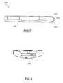
- FIG. 7 is a top view of the interspinous spacer implant of FIG. 5 ;
- FIG. 8 is a side view of the interspinous spacer implant of FIG. 5 ;
- FIG. 9A is a perspective view of another embodiment of the interspinous spacer implant.
- FIG. 9B is a side view of the interspinous spacer implant of FIG. 9A ;
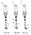
- FIG. 10A is a perspective view of a spacer insertion tool used to insert the interspinous spacer implant from the front;
- FIG. 10B is a perspective view of the spacer insertion tool of FIG. 10A in the secured position
- FIG. 10C is a perspective view of a spacer insertion tool used to insert the interspinous spacer implant from the side;
- FIG. 11 is a detailed view of the end effector of the spacer insertion tool used to insert the interspinous spacer implant from the front;
- FIG. 12 is a detailed view of the end effector of the spacer insertion tool used to insert the interspinous spacer implant from the side;
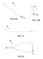
- FIG. 13A is a schematic view of flat rasp tool
- FIG. 13B is a schematic view of a round rasp tool
- FIG. 14 is a schematic view of a hooked dilator
- FIG. 15 is a schematic view of a hub sizer tool
- FIG. 16 is a schematic view of the inserter tool.
- FIG. 17 is a schematic view of a handle used in connection with the inserter tool of FIG. 16 .
- the present invention relates to a system and a method for an improved spinous process fixation implant assembly 50 , shown in FIG. 2 .
- the spinous process fixation implant assembly 50 includes a spinous process fixation implant 100 and an interspinous spacer implant 200 .
- the spinous process fixation implant 100 includes elongated first and second components 110 , 120 , that are arranged opposite and parallel to each other.
- First and second spinous processes 90 a , 90 b of first and second adjacent vertebrae 80 a , 80 b are clamped between the first and second components 110 , 120 , respectively, and are separated by the interspinous spacer implant 200 , as shown in FIG. 2 and FIG. 3 .
- spinous process fixation implant 100 includes first elongated component 110 , second elongated component 120 , top and bottom pins, 180 a , 180 b , and set screws 140 a , 140 b .
- First component 110 includes an elongated body 112 and one integral post 170 a .
- Elongated body 112 has an essentially parallelepiped structure having parallel front and back surfaces 112 a , 112 b , parallel left and right side surfaces 112 c , 112 d and parallel top and bottom surfaces 112 e , 112 f , respectively.
- Elongated body 112 is convexly curved so that its top and bottom portions 111 , 113 protrude forward relative to its middle portion 115 , as shown in FIG. 4C .
- Middle portion 115 includes an opening 172 a extending from the left surface 112 c to the right surface 112 d .
- Top portion 111 includes teeth 109 protruding from the top of right surface 112 d .
- Bottom portion 113 also includes teeth 109 protruding from the bottom of right surface 112 d .
- Opening 172 a has a semi-circular cross-section and is dimensioned to be slightly larger than or equal to the dimensions of post 170 b of component 120 , so that post 170 b can pass through it.
- Middle portion 115 also includes a cylindrical projection 115 a having an opening 116 a extending from the top surface 112 a to the back surface 112 b . Opening 116 a receives set screw 140 a and has dimensions matching the dimensions of screw 140 a . Screw 140 a secures the position of post 170 b of the second component 120 onto post 170 a of the first component 110 within opening 172 a .
- Post 170 a is integral with component 110 and has an essentially hollow semi-cylindrical structure.
- Post 170 a extends perpendicularly to the right side surface 112 d of the elongated body 112 from its middle portion 115 .
- Post 170 a is adjacent to opening 172 a and is oriented so that its cross-section forms a full circle together with the semi-circular opening 172 a , as shown in FIG. 4C .
- second component 120 is the same as the first component 110 and is rotated 180 degrees relative to the orientation of the first component 110 .
- Second component 120 includes an elongated body 122 and one integral post 170 b .
- Elongated body 122 has an essentially parallelepiped structure having parallel front and back surfaces 122 a , 122 b , parallel left and right side surfaces 122 c , 122 d and parallel top and bottom surfaces 122 e , 122 f , respectively.
- Elongated body 122 is also convexly curved so that its top and bottom portions 121 , 123 protrude forward relative to its middle portion 125 .
- Middle portion 125 includes an opening 172 b extending from the left surface 122 c to the right surface 122 d .
- Top portion 121 includes teeth 109 protruding from the top of right surface 122 d .
- Bottom portion 123 also includes teeth 109 protruding from the bottom of right surface 122 d .
- Opening 172 b has a semi-circular cross-section and is dimensioned to be slightly larger than or equal to the dimensions of post 170 a of component 110 , so that post 170 a can pass through it.
- Middle portion 125 also includes a cylindrical projection 125 a having an opening 116 b extending from the top surface 122 a to the back surface 122 b .
- Opening 116 b receives set screw 140 b and has dimensions matching the dimensions of screw 140 a .
- Screw 140 a secures the position of post 170 a of the first component 110 onto post 170 b of the second component 120 within opening 172 b .
- Post 170 b is integral with component 120 and has an essentially hollow semi-cylindrical structure 182 , shown in FIG. 4G .
- Post 170 b extends perpendicularly to the right side surface 122 d of the elongated body 122 from its middle portion 125 .
- Post 170 b is adjacent to opening 172 b and is oriented so that its cross-section forms a full circle together with the semi-circular opening 172 b .
- Posts 170 a , 170 b have tapered front ends 171 a , 171 b . Tapered front ends 171 a , 171 b , help the insertion of the posts 170 a , 170 b through the interspinous area 85 and the openings 172 b , 172 a , respectively.
- elongated body 122 of component 120 is not curved, and the top and bottom portions 121 , 123 do not protrude relative to the middle portion 125 , as shown in FIG. 4F and FIG. 4E .
- elongated body 112 of component 110 is not curved.
- the front ends 171 a , 171 b of posts 170 a , 170 b are closed off and chamfered, as shown in FIG. 4E .
- interspinous spacer implant 200 includes an elongated body having a front surface 202 , back surface 204 , bottom surface 206 , top surface 208 , left side surface 209 and right side surface 210 .
- Implant 200 also includes openings 212 , 214 and 216 extending from the front surface 202 to the back surface 204 .
- Top and bottom surfaces 206 , 208 also include central recesses 207 a , 207 b , respectively.
- Central recesses 207 a , 207 b are dimensioned to receive the upper the lower spinous processes 90 a , 90 b , respectively, as shown in FIG. 3 .
- top and bottom surfaces 206 a , 208 a are angled, thereby resulting in a narrow right side surface 210 .
- Right side surface 210 is multifaceted and includes surfaces 211 , 212 , 213 , shown in FIG. 7 and FIG. 8 .
- Back surface 204 is convexly curved 220 , as shown in FIG. 8 .
- the front surface 202 includes an elongated recess 222 extending the length of the implant, as shown in FIG. 9A .
- the back surface 220 is flat, as shown in FIG. 9B .
- interspinous spacer implant 200 is made of bone and has a length of 30 mm, thickness in the center 3.5 mm, thickness at the sides 2.75 mm and a width of 10 mm.
- the width of the implant varies between 8 mm to 20 mm depending upon the distance between the adjacent spinous processes 90 a , 90 b.
- the surgical technique for spinal stabilization using the spinous process fixation implant assembly 50 of FIG. 2 includes the following steps. First the allograft interspinous fusion spacer 200 is reconstituted by soaking in a saline solution. Next, a hooked dilator 290 , shown in FIG. 14 , is used to punch an opening through the anterior region of the interspinous ligament. The opening needs to be large enough to be able to accommodate both the spacer 200 and posts 170 a , 170 b of the fixation implant 100 . Next, a distractor 300 , shown in FIG. 15 , is inserted into the opening and is used to spread the spinous processes 90 a , 90 b apart.
- the spinous processes 90 a , 90 b are spread apart and the distraction height 230 is measured.
- the measured distraction height 230 is used to determine the width of the spacer implant.
- the distractor 300 has a sliding collar on a bar at the top of the instrument that indicates the width and which standard spacer implant to use.
- Distraction height 230 can also be determined by using various sized round rasps ranging from 8-20 mm, shown in FIG. 13B .
- the measurement indicated on the distractor equals the center vertical width at the waist of the spacer.
- the lamina, spinous processes and anterior portions around the prepared opening are roughened up using the flat or round rasp 280 , shown in FIG. 13A and FIG. 13B , respectively.
- Inserter 250 includes the inserter component 240 , shown in FIG. 16 and removable handle 260 , shown in FIG. 17 .
- Inserter 250 includes the inserter component 240 , shown in FIG. 16 and removable handle 260 , shown in FIG. 17 .
- There are two ways to insert the spacer 200 front-back insertion and lateral insertion.
- front-back insertion the interspinous ligament needs to be removed first.
- the two prongs 256 a , 256 b of the inserter end effector 255 are inserted in openings 212 , 214 of spacer 200 , as shown in FIG. 11 and FIG. 10A , and the inserter sleeve 242 is moved down along direction 260 , shown in FIG.
- Inserter sleeve 242 is moved down along direction 260 by rotating the knob 244 clockwise below the handle 260 . Moving the sleeve 242 down compresses the two prongs 256 a , 256 b together and thereby creates a secure connection between the spacer 200 and the inserter 250 .
- the spacer 200 is inserted from the front perpendicular to directions H-H′ and V-V′ in the prepared opening between the spinous processes, shown in FIG. 3 .
- the spacer 200 is oriented at approximately 45 degrees angle relative to the opening and is inserted until the waist 207 a is between the spinous processes 90 a , 90 b and the midpoint of the spacer is in the interspinous space 85 .
- the inserter 250 is turned 45 degrees in the cephalad direction to place the spacer in the preferred position and to secure it in place.
- the knob 244 is turned counter-clockwise to loosen the prongs 256 a , 256 b , to gradually raise the sleeve 242 and then to remove the inserter prongs 256 a , 256 b from the spacer 200 .
- one prong 256 a is inserted in the outer notch 216 and the other 256 b is inserted in the adjacent opening 214 .
- the center of the inserter 250 is at the side opposite the chamfered side 210 of the spacer 200 .
- the inserter 250 may be oriented either horizontally along H-H′ or vertically along VV′, shown in FIG. 3 . In either case the spacer 200 is inserted from the side along direction 262 .
- the spacer 200 may be used to distract the spinous processes 90 a , 90 b by up to 2 mm in each direction before the center of the spacer is in the preferred location.
- the spinous fixation implant 100 is inserted and attached to the sides of the spinous processes 90 a , 90 b . If the interspinous opening is large enough to accommodate both the spacer 200 and the vertical posts 170 a , 170 b of the spinous fixation implant 100 , the same opening is used for the spacer 200 and the fixation implant 100 . In cases where the interspinous opening is not large enough, a second opening is punched with the hooked dilator 290 for accommodating the fixation implant 100 . The spinous processes may need to be further distracted with distractor 300 in order to accommodate the fixation implant 100 .
- first component 110 is placed in contact with the left sides of top and bottom spinous process 90 a , 90 b of adjacent vertebrae 80 a , 80 b , respectively, as shown in FIG. 4D .
- Post 170 a is placed in the second interspinous opening between the top and bottom spinous processes 90 a , 90 b .
- second component 120 is placed in contact with the right sides of top and bottom spinous process 90 a , 90 b of adjacent vertebrae 80 a , 80 b , respectively.
- Post 170 a of the first component 110 is inserted into opening 172 b of the second component 120
- post 170 b of the second component 120 is inserted into openings 172 a of the first component 110 .
Abstract
Description
Claims (6)
Priority Applications (1)
| Application Number | Priority Date | Filing Date | Title |
|---|---|---|---|
| US13/411,478 US9498560B2 (en) | 2011-03-04 | 2012-03-02 | Interspinous spacer implant |
Applications Claiming Priority (3)
| Application Number | Priority Date | Filing Date | Title |
|---|---|---|---|
| US201161449274P | 2011-03-04 | 2011-03-04 | |
| US13/182,525 US20110270401A1 (en) | 2000-03-10 | 2011-07-14 | Synthetic reinforced interbody fusion implants |
| US13/411,478 US9498560B2 (en) | 2011-03-04 | 2012-03-02 | Interspinous spacer implant |
Related Parent Applications (1)
| Application Number | Title | Priority Date | Filing Date |
|---|---|---|---|
| US13/182,525 Continuation-In-Part US20110270401A1 (en) | 2000-03-10 | 2011-07-14 | Synthetic reinforced interbody fusion implants |
Publications (2)
| Publication Number | Publication Date |
|---|---|
| US20120226314A1 US20120226314A1 (en) | 2012-09-06 |
| US9498560B2 true US9498560B2 (en) | 2016-11-22 |
Family
ID=46753763
Family Applications (1)
| Application Number | Title | Priority Date | Filing Date |
|---|---|---|---|
| US13/411,478 Active 2032-12-10 US9498560B2 (en) | 2011-03-04 | 2012-03-02 | Interspinous spacer implant |
Country Status (1)
| Country | Link |
|---|---|
| US (1) | US9498560B2 (en) |
Families Citing this family (19)
| Publication number | Priority date | Publication date | Assignee | Title |
|---|---|---|---|---|
| US9402656B2 (en) * | 2009-09-11 | 2016-08-02 | Globus Medical, Inc. | Spinous process fusion devices |
| EP2544635B1 (en) | 2010-03-12 | 2018-09-19 | Southern Spine, LLC | Interspinous process spacing device and implantation tools |
| US10945858B2 (en) | 2010-09-03 | 2021-03-16 | Globus Medical, Inc. | Expandable interspinous process fixation device |
| US10512550B2 (en) | 2010-09-03 | 2019-12-24 | Globus Medical, Inc. | Expandable interspinous process fixation device |
| US8876866B2 (en) * | 2010-12-13 | 2014-11-04 | Globus Medical, Inc. | Spinous process fusion devices and methods thereof |
| US20120323276A1 (en) * | 2011-06-17 | 2012-12-20 | Bryan Okamoto | Expandable interspinous device |
| USD757943S1 (en) | 2011-07-14 | 2016-05-31 | Nuvasive, Inc. | Spinous process plate |
| US8882805B1 (en) | 2011-08-02 | 2014-11-11 | Lawrence Maccree | Spinal fixation system |
| US10448977B1 (en) | 2012-03-31 | 2019-10-22 | Ali H. MESIWALA | Interspinous device and related methods |
| CN104602629A (en) | 2012-08-31 | 2015-05-06 | 新南创新公司 | Bone stabilization device and methods of use |
| US8906065B2 (en) * | 2012-10-22 | 2014-12-09 | Spectrum Spine Ip Holdings, Llc | Inter-spinous process device and method |
| US9668786B2 (en) | 2012-11-16 | 2017-06-06 | Southern Spine, Llc | Linkage systems for interspinous process spacing device |
| US9510872B2 (en) * | 2013-03-15 | 2016-12-06 | Jcbd, Llc | Spinal stabilization system |
| US9592083B2 (en) | 2013-08-30 | 2017-03-14 | New South Innovations Pty Limited | Spine stabilization device |
| US9259249B2 (en) * | 2013-11-26 | 2016-02-16 | Globus Medical, Inc. | Spinous process fixation system and methods thereof |
| CN106725789A (en) * | 2016-12-30 | 2017-05-31 | 上海凯利泰医疗科技股份有限公司 | Fixing device between a kind of spinous process |
| EP3434229B1 (en) * | 2017-07-28 | 2020-04-15 | Globus Medical, Inc. | Expandable interspinous process fixation device |
| US11432937B1 (en) | 2021-11-02 | 2022-09-06 | Linares Medical Devices, Llc | Expandable spinal jack for installation between upper and lower succeeding superior articular processes |
| WO2023099224A1 (en) * | 2021-12-02 | 2023-06-08 | Symed Device S.R.L. | Interspinous-intraspinous prosthesis |
Citations (18)
| Publication number | Priority date | Publication date | Assignee | Title |
|---|---|---|---|---|
| US20040162617A1 (en) | 1998-10-20 | 2004-08-19 | St. Francis Medical Technologies, Inc. | Mating insertion instruments for spinal implants and methods of use |
| US20060241610A1 (en) * | 2005-04-08 | 2006-10-26 | Sdgi Holdings, Inc. | Interspinous process spacer |
| US20060264939A1 (en) | 2003-05-22 | 2006-11-23 | St. Francis Medical Technologies, Inc. | Interspinous process implant with slide-in distraction piece and method of implantation |
| US20070016303A1 (en) | 2005-06-06 | 2007-01-18 | Jackson Benjamin L | Implant for spinal stabilization and its method of use |
| US20070093825A1 (en) * | 2005-09-28 | 2007-04-26 | Nuvasive Inc. | Methods and apparatus for treating spinal stenosis |
| US20080033552A1 (en) | 2004-05-17 | 2008-02-07 | Canon Kasushiki Kaisha | Sensor Device |
| US20090138046A1 (en) | 2004-10-20 | 2009-05-28 | Moti Altarac | Interspinous spacer |
| US20090234389A1 (en) | 2008-03-11 | 2009-09-17 | Fong-Ying Chuang | Interspinous spinal fixation apparatus |
| US20090306715A1 (en) | 2006-02-01 | 2009-12-10 | Jackson Benjamin L | Interspinous process spacer |
| US20100106191A1 (en) | 2008-08-27 | 2010-04-29 | Yue James J | Conical interspinous apparatus and a method of performing interspinous distraction |
| US7749252B2 (en) | 2005-03-21 | 2010-07-06 | Kyphon Sarl | Interspinous process implant having deployable wing and method of implantation |
| US20100174316A1 (en) | 2003-05-22 | 2010-07-08 | Kyphon Sarl | Distractible interspinous process implant and method of implantation |
| US7771456B2 (en) | 2004-08-13 | 2010-08-10 | Synthes Usa, Llc | Interspinous implant |
| US20100222817A1 (en) | 2006-12-28 | 2010-09-02 | Mi4Spine, Llc | Interspinous process spacer device including a rotatable retaining member |
| US7828822B2 (en) | 1997-01-02 | 2010-11-09 | Kyphon SÀRL | Spinous process implant |
| US20110054533A1 (en) | 2009-08-26 | 2011-03-03 | Binder Lawrence J | Spinous fusion device |
| US8048117B2 (en) | 2003-05-22 | 2011-11-01 | Kyphon Sarl | Interspinous process implant and method of implantation |
| US20110307010A1 (en) | 2010-02-18 | 2011-12-15 | Osprey Biomedical Corp. | Interspinous device and method of implanting |
-
2012
- 2012-03-02 US US13/411,478 patent/US9498560B2/en active Active
Patent Citations (18)
| Publication number | Priority date | Publication date | Assignee | Title |
|---|---|---|---|---|
| US7828822B2 (en) | 1997-01-02 | 2010-11-09 | Kyphon SÀRL | Spinous process implant |
| US20040162617A1 (en) | 1998-10-20 | 2004-08-19 | St. Francis Medical Technologies, Inc. | Mating insertion instruments for spinal implants and methods of use |
| US20100174316A1 (en) | 2003-05-22 | 2010-07-08 | Kyphon Sarl | Distractible interspinous process implant and method of implantation |
| US20060264939A1 (en) | 2003-05-22 | 2006-11-23 | St. Francis Medical Technologies, Inc. | Interspinous process implant with slide-in distraction piece and method of implantation |
| US8048117B2 (en) | 2003-05-22 | 2011-11-01 | Kyphon Sarl | Interspinous process implant and method of implantation |
| US20080033552A1 (en) | 2004-05-17 | 2008-02-07 | Canon Kasushiki Kaisha | Sensor Device |
| US7771456B2 (en) | 2004-08-13 | 2010-08-10 | Synthes Usa, Llc | Interspinous implant |
| US20090138046A1 (en) | 2004-10-20 | 2009-05-28 | Moti Altarac | Interspinous spacer |
| US7749252B2 (en) | 2005-03-21 | 2010-07-06 | Kyphon Sarl | Interspinous process implant having deployable wing and method of implantation |
| US20060241610A1 (en) * | 2005-04-08 | 2006-10-26 | Sdgi Holdings, Inc. | Interspinous process spacer |
| US20070016303A1 (en) | 2005-06-06 | 2007-01-18 | Jackson Benjamin L | Implant for spinal stabilization and its method of use |
| US20070093825A1 (en) * | 2005-09-28 | 2007-04-26 | Nuvasive Inc. | Methods and apparatus for treating spinal stenosis |
| US20090306715A1 (en) | 2006-02-01 | 2009-12-10 | Jackson Benjamin L | Interspinous process spacer |
| US20100222817A1 (en) | 2006-12-28 | 2010-09-02 | Mi4Spine, Llc | Interspinous process spacer device including a rotatable retaining member |
| US20090234389A1 (en) | 2008-03-11 | 2009-09-17 | Fong-Ying Chuang | Interspinous spinal fixation apparatus |
| US20100106191A1 (en) | 2008-08-27 | 2010-04-29 | Yue James J | Conical interspinous apparatus and a method of performing interspinous distraction |
| US20110054533A1 (en) | 2009-08-26 | 2011-03-03 | Binder Lawrence J | Spinous fusion device |
| US20110307010A1 (en) | 2010-02-18 | 2011-12-15 | Osprey Biomedical Corp. | Interspinous device and method of implanting |
Also Published As
| Publication number | Publication date |
|---|---|
| US20120226314A1 (en) | 2012-09-06 |
Similar Documents
| Publication | Publication Date | Title |
|---|---|---|
| US9498560B2 (en) | Interspinous spacer implant | |
| US9913668B2 (en) | Interspinous fixation implant | |
| US8425612B2 (en) | Minimally invasive interbody device assembly | |
| US7282064B2 (en) | Apparatus and method for connecting spinal vertebrae | |
| US20110307010A1 (en) | Interspinous device and method of implanting | |
| US8372118B2 (en) | Spinous process fixation implant | |
| US8758408B2 (en) | Spinous process fixation implant | |
| US20230293206A1 (en) | Spinal Fixation Construct And Methods Of Use | |
| EP1490002B1 (en) | Apparatus for replacing vertebral elements | |
| US8100945B2 (en) | Intervertebral prosthetic device for spinal stabilization and method of implanting same | |
| EP1903965B1 (en) | Intervertebral prosthetic device for spinal stabilization | |
| US6461359B1 (en) | Spine stabilization device | |
| US20080114358A1 (en) | Intervertebral Prosthetic Assembly for Spinal Stabilization and Method of Implanting Same | |
| US20090005818A1 (en) | Dynamic facet replacement system | |
| US20060264941A1 (en) | Pedicle screw-based dynamic posterior stabilization systems and methods | |
| EP3015084B1 (en) | Spinal fixation member | |
| US8506598B1 (en) | Anchors for spinal fixation and correcting spinal deformity | |
| US20120245693A1 (en) | Spinal fixation device | |
| US10448977B1 (en) | Interspinous device and related methods |
Legal Events
| Date | Code | Title | Description |
|---|---|---|---|
| STCF | Information on status: patent grant |
Free format text: PATENTED CASE |
|
| FEPP | Fee payment procedure |
Free format text: SURCHARGE FOR LATE PAYMENT, SMALL ENTITY (ORIGINAL EVENT CODE: M2554); ENTITY STATUS OF PATENT OWNER: SMALL ENTITY |
|
| MAFP | Maintenance fee payment |
Free format text: PAYMENT OF MAINTENANCE FEE, 4TH YR, SMALL ENTITY (ORIGINAL EVENT CODE: M2551); ENTITY STATUS OF PATENT OWNER: SMALL ENTITY Year of fee payment: 4 |
|
| AS | Assignment |
Owner name: KIC VENTURES, LLC, MASSACHUSETTS Free format text: ASSIGNMENT OF ASSIGNORS INTEREST;ASSIGNOR:SPINEFRONTIER, INC;REEL/FRAME:053971/0594 Effective date: 20190701 |