US9498619B2 - Implantable electrical stimulation leads - Google Patents
Implantable electrical stimulation leads Download PDFInfo
- Publication number
- US9498619B2 US9498619B2 US14/191,085 US201414191085A US9498619B2 US 9498619 B2 US9498619 B2 US 9498619B2 US 201414191085 A US201414191085 A US 201414191085A US 9498619 B2 US9498619 B2 US 9498619B2
- Authority
- US
- United States
- Prior art keywords
- lead
- distal end
- branch
- electrically conductive
- length
- Prior art date
- Legal status (The legal status is an assumption and is not a legal conclusion. Google has not performed a legal analysis and makes no representation as to the accuracy of the status listed.)
- Active - Reinstated, expires
Links
Images


Classifications
-
- A—HUMAN NECESSITIES
- A61—MEDICAL OR VETERINARY SCIENCE; HYGIENE
- A61N—ELECTROTHERAPY; MAGNETOTHERAPY; RADIATION THERAPY; ULTRASOUND THERAPY
- A61N1/00—Electrotherapy; Circuits therefor
- A61N1/02—Details
- A61N1/04—Electrodes
- A61N1/05—Electrodes for implantation or insertion into the body, e.g. heart electrode
- A61N1/0507—Electrodes for the digestive system
- A61N1/0509—Stomach and intestinal electrodes
-
- A—HUMAN NECESSITIES
- A61—MEDICAL OR VETERINARY SCIENCE; HYGIENE
- A61B—DIAGNOSIS; SURGERY; IDENTIFICATION
- A61B1/00—Instruments for performing medical examinations of the interior of cavities or tubes of the body by visual or photographical inspection, e.g. endoscopes; Illuminating arrangements therefor
- A61B1/00064—Constructional details of the endoscope body
- A61B1/00071—Insertion part of the endoscope body
- A61B1/0008—Insertion part of the endoscope body characterised by distal tip features
- A61B1/00082—Balloons
-
- A—HUMAN NECESSITIES
- A61—MEDICAL OR VETERINARY SCIENCE; HYGIENE
- A61B—DIAGNOSIS; SURGERY; IDENTIFICATION
- A61B1/00—Instruments for performing medical examinations of the interior of cavities or tubes of the body by visual or photographical inspection, e.g. endoscopes; Illuminating arrangements therefor
- A61B1/00064—Constructional details of the endoscope body
- A61B1/00071—Insertion part of the endoscope body
- A61B1/0008—Insertion part of the endoscope body characterised by distal tip features
- A61B1/00087—Tools
-
- A—HUMAN NECESSITIES
- A61—MEDICAL OR VETERINARY SCIENCE; HYGIENE
- A61B—DIAGNOSIS; SURGERY; IDENTIFICATION
- A61B18/00—Surgical instruments, devices or methods for transferring non-mechanical forms of energy to or from the body
- A61B18/04—Surgical instruments, devices or methods for transferring non-mechanical forms of energy to or from the body by heating
- A61B18/08—Surgical instruments, devices or methods for transferring non-mechanical forms of energy to or from the body by heating by means of electrically-heated probes
- A61B18/082—Probes or electrodes therefor
-
- A—HUMAN NECESSITIES
- A61—MEDICAL OR VETERINARY SCIENCE; HYGIENE
- A61F—FILTERS IMPLANTABLE INTO BLOOD VESSELS; PROSTHESES; DEVICES PROVIDING PATENCY TO, OR PREVENTING COLLAPSING OF, TUBULAR STRUCTURES OF THE BODY, e.g. STENTS; ORTHOPAEDIC, NURSING OR CONTRACEPTIVE DEVICES; FOMENTATION; TREATMENT OR PROTECTION OF EYES OR EARS; BANDAGES, DRESSINGS OR ABSORBENT PADS; FIRST-AID KITS
- A61F5/00—Orthopaedic methods or devices for non-surgical treatment of bones or joints; Nursing devices; Anti-rape devices
- A61F5/0003—Apparatus for the treatment of obesity; Anti-eating devices
- A61F5/0013—Implantable devices or invasive measures
- A61F5/0026—Anti-eating devices using electrical stimulation
-
- A—HUMAN NECESSITIES
- A61—MEDICAL OR VETERINARY SCIENCE; HYGIENE
- A61N—ELECTROTHERAPY; MAGNETOTHERAPY; RADIATION THERAPY; ULTRASOUND THERAPY
- A61N1/00—Electrotherapy; Circuits therefor
- A61N1/18—Applying electric currents by contact electrodes
- A61N1/32—Applying electric currents by contact electrodes alternating or intermittent currents
- A61N1/36—Applying electric currents by contact electrodes alternating or intermittent currents for stimulation
- A61N1/36007—Applying electric currents by contact electrodes alternating or intermittent currents for stimulation of urogenital or gastrointestinal organs, e.g. for incontinence control
-
- A—HUMAN NECESSITIES
- A61—MEDICAL OR VETERINARY SCIENCE; HYGIENE
- A61B—DIAGNOSIS; SURGERY; IDENTIFICATION
- A61B17/00—Surgical instruments, devices or methods, e.g. tourniquets
- A61B17/00234—Surgical instruments, devices or methods, e.g. tourniquets for minimally invasive surgery
- A61B2017/00292—Surgical instruments, devices or methods, e.g. tourniquets for minimally invasive surgery mounted on or guided by flexible, e.g. catheter-like, means
- A61B2017/0034—Surgical instruments, devices or methods, e.g. tourniquets for minimally invasive surgery mounted on or guided by flexible, e.g. catheter-like, means adapted to be inserted through a working channel of an endoscope
-
- A—HUMAN NECESSITIES
- A61—MEDICAL OR VETERINARY SCIENCE; HYGIENE
- A61B—DIAGNOSIS; SURGERY; IDENTIFICATION
- A61B18/00—Surgical instruments, devices or methods for transferring non-mechanical forms of energy to or from the body
- A61B2018/00571—Surgical instruments, devices or methods for transferring non-mechanical forms of energy to or from the body for achieving a particular surgical effect
- A61B2018/00595—Cauterization
Definitions
- the present specification relates generally to implantable leads used in the electrical stimulation of human tissues. More particularly, the present specification relates to implantable electrical stimulation leads useful in the stimulation of anatomical structures proximate the gastroesophageal junction.
- Electrical stimulation of nerves and surrounding tissue is used to treat a variety of conditions.
- electrical stimulation can be used to restore partial function to limbs or organs following traumatic injury. Electrical stimulation can also be used to reduce pain.
- electrical stimulation can be used to treat disorders associated with the gastrointestinal (GI) system, such as, obesity and gastroesophageal reflux disease (GERD).
- GI gastrointestinal
- GERD gastroesophageal reflux disease
- Obesity is a common condition and a major public health problem in developed countries including the United States of America. As of 2009, more than two thirds of American adults, approximately 127 million people, were either overweight or obese. Data suggest that 300,000 Americans die prematurely from obesity-related complications each year. Many children in the United States are also either overweight or obese. Hence, the overall number of overweight Americans is expected to rise in the future. It has been estimated that obesity costs the United States approximately $100 billion annually in direct and indirect health care expenses and in lost productivity. This trend is also apparent in many other developed countries.
- the body mass index is used to determine if one is overweight or obese.
- a person's BMI is calculated by multiplying body weight in pounds by 703 and then dividing the total by height in inches squared.
- a person's BMI is expressed as kilograms per meter squared.
- An adult is considered overweight if his or her BMI is between 25 and 30 kg/m2.
- Obesity is defined as possessing a BMI between 30 and 40 kg/m2.
- a BMI greater than 30 kg/m 2 is associated with significant co-morbidities.
- Morbid obesity is defined as possessing either a body weight more than 100 pounds greater than ideal or a body mass index (BMI) greater than 40 kg/m 2 . Approximately 5% of the U.S.
- Morbid obesity is associated with many diseases and disorders including, for example: diabetes; hypertension; heart attacks; strokes; dyslipidemia; sleep apnea; pickwickian syndrome; asthma; lower back and disc disease; weight-bearing osteoarthritis of the hips, knees, ankles and feet; thrombophlebitis and pulmonary emboli; intertriginous dermatitis; urinary stress incontinence; gastroesophageal reflux disease (GERD); gallstones; and, sclerosis and carcinoma of the liver.
- GSD gastroesophageal reflux disease
- sclerosis and carcinoma of the liver In women, infertility, cancer of the uterus, and cancer of the breast are also associated with morbid obesity. Taken together, the diseases associated with morbid obesity markedly reduce the odds of attaining an average lifespan. The sequelae raise annual mortality in affected people by a factor of 10 or more.
- Gastro-esophageal reflux disease is another common health problem and is expensive to manage in both primary and secondary care settings. This condition results from exposure of esophageal mucosa to gastric acid as the acid refluxes from the stomach into the esophagus. The acid damages the esophageal mucosa resulting in heartburn, ulcers, bleeding, and scarring, and long term complications such as Barrett's esophagus (pre-cancerous esophageal lining) and adeno-cancer of the esophagus.
- GSD Gastro-esophageal reflux disease
- GES Gastric electrical stimulation
- GES employs an implantable, pacemaker-like device to deliver low-level electrical stimulation to the gastrointestinal tract.
- GES operates by disrupting the motility cycle and/or stimulating the enteric nervous system, thereby increasing the duration of satiety experienced by the patient.
- the procedure involves the surgeon suturing electrical leads to the outer lining of the stomach wall. The leads are then connected to the device, which is implanted just under the skin in the abdomen. Using an external programmer that communicates with the device, the surgeon establishes the level of electrical stimulation appropriate for the patient.
- the Abiliti® implantable gastric stimulation device manufactured by IntraPace, is currently available in Europe for treatment of obesity.
- Medtronic offers for sale and use the EnterraTM Therapy, which is indicated for the treatment of chronic nausea and vomiting associated with gastroparesis when conventional drug therapies are not effective.
- the EnterraTM Therapy uses mild electrical pulses to stimulate the stomach. According to Medtronic, this electrical stimulation helps control the symptoms associated with gastroparesis, including nausea and vomiting.
- Electrode sets are placed in the esophagus in an arrangement that induce contractions of the LES by electrical stimulation of the surrounding tissue and nerves.
- the electrical stimulus is applied by a pulse generator for periods of varying duration and varying frequency so as to produce the desired contractions.
- the treatment may be short-term or may continue throughout the life of the patient in order to achieve the desired therapeutic effect.
- the stimulating electrode sets can be used either alone or in conjunction with electrodes that sense esophageal peristalsis.
- the electrode sets can be placed endoscopically, surgically or radiologically.”
- the referenced invention relies on sensing certain physiological changes in the esophagus, such as changes in esophageal pH, to detect acid reflux. Once a change in esophageal pH is recognized, the system generates an electrical stimulation in an attempt to instantaneously close the LES and abort the episode of acid reflux.
- U.S. Pat. No. 6,901,295 is hereby incorporated by reference in its entirety.
- the leads used in electrical stimulation of gastrointestinal tissues traditionally comprise elongated or coiled, insulated wires or cables having a means for attachment to an electrical pulse generator at one end and one or more exposed electrodes at the other end.
- the leads are typically anchored in place such that the electrodes are positioned and remain proximate the target nerve or tissues. Anchoring is often accomplished by suturing the electrode containing ends of the leads proximal to the electrodes and into the surrounding tissue.
- Traditional leads often comprise a needle attached to a length of suture nylon at the distal end of each branch of the lead.
- a butterfly shaped anchoring element is positioned on each branch just proximal to each electrode.
- the needle and suture nylon are used to create a pathway for the electrode to be inserted into the tissue, with the needle and most of the suture being removed thereafter.
- the remaining suture is used as a tether onto which at least one clip (e.g., titanium clip) is used to provide a distal stop thus preventing the electrode from backing out until sufficient fibrosis is formed.
- at least one clip e.g., titanium clip
- While current electrical leads are effective in transmitting electrical stimulation to target nerves and tissues, they are not without their drawbacks.
- the overall length of current leads limits the implantation site of the stimulator to which they connect.
- a lead that is intended to have its electrodes positioned proximate the gastroesophageal junction is often implanted through the abdominal wall via laparoscopy, but requiring the stimulator and its unsightly scar at the patient's exposed abdomen. Therefore, what is needed is a lead having an increased overall length to permit stimulator implantation at points further from the therapy site, whereby the scar could be covered by most clothing apparel (e.g., male and female swimsuits) or the implant access could be through the umbilicus.
- bipolar leads the monopolar branches that extend beyond the bifurcation point are often too long. Lengthy monopolar branches can become entangled in surrounding tissues, leading to dislodgment of anchored leads and stricture formation. Therefore, what is needed is a bipolar lead having shortened monopolar branches. Further, traditional leads are often pulled backward to facilitate anchoring, causing the proximal 2 to 3 mm of conductive material to become exposed. Exposed conductive material can result in inadvertent electrical stimulation of non-target tissues as well as less stimulation current reaching the target tissues. Therefore, what is also needed is a lead having additional insulation closer to the electrodes.
- Traditional leads also include electrodes that are too large for certain applications, including stimulation of the gastroesophageal junction. Oversized electrodes can also result in inadvertent electrical stimulation of non-target tissues. Therefore, what is needed is a lead having smaller sized electrodes.
- the space in which to work surrounding the gastroesophageal junction (GEJ) is relatively confined compared to other spaces, such as, around the body of the stomach.
- Traditional leads having long suture nylons tempt the surgeon to use the same needle and suture for anchoring the lead proximal to the electrode; however, this suture material is chosen for applying distal clips and not anchoring the leads.
- a lead having shorter suture nylons on each branch such that this needle and suture is not long enough to be used for anchoring the leads proximal to the electrode. Having shorter suture nylons also reduces the number of pulling maneuvers required in order to bring the electrode(s) into final position.
- Traditional leads often include a curved needle for anchoring. The degree of curvature of the needle is often not sufficient when considering the adjacent tissues, resulting in injury to the tissue. What is needed is a needle curvature which will allow the user to significantly bury the electrode within the target tissue while also making the needle easily retrievable from the tissue exit site without puncturing or scraping nearby tissues.
- a lead having a needle with a degree of curvature specific to the target and surrounding tissue Some traditional leads include an additional suture sleeve over the lead body to prevent damage to surrounding tissues during implantation. However, this sleeve tends to attract much fibrosis. Therefore, what is also needed is a lead having no additional anchoring sleeve.
- an implantable electrical lead for use in the stimulation of biological tissues, said lead comprising: an elongate lead body having a proximal end and a distal end, said lead body comprising an electrically conductive inner coil, an electrically conductive outer coil, a first insulating sheath covering said inner coil, and a second insulating sheath covering said outer coil wherein said lead body has a length within a range of 390 mm to 490 mm; a connector attached to and in electrical communication with said proximal end of said lead body; a first elongate branch having a proximal end and a distal end, said first elongate branch comprising said inner coil and said first insulating sheath covering said inner coil and not comprising said outer coil and said second insulating sheath, wherein said first branch has a length within a range of 50 mm to 120 mm; a second elongate branch having a proximal end and a distal end, said second elonglongate branch having
- the implantable electrical lead further comprises a first length of suturing material and a second length of suturing material, each having a proximal end and a distal end, wherein said proximal end of said first length of said suturing material is attached to said distal end of said first branch and said proximal end of said second length of said suturing material is attached to said distal end of said second branch.
- the first and second lengths of suturing material are each in a range of 55 to 65 mm.
- the implantable electrical lead further comprises a first needle attached to said distal end of said first length of suturing material and a second needle attached to said distal end of said second length of suturing material, wherein said first needle and said first length of suturing material are used to suture said first anchoring element to a biological tissue and said second needle and said second length of suturing material are used to suture said second anchoring element to a biological tissue.
- the first and second needles are each within a range of 1 ⁇ 4 to 3 ⁇ 8 of a circle curve needles with a length ranging from 18 to 23 mm and include a base having a diameter in a range of 0.68 mm to 0.78 mm.
- said lead further comprises an additional electrically conductive coil having a proximal end and a distal end and comprising said second branch, wherein said proximal end of said additional coil is attached to said distal end of said outer coil and said second anchoring element and said second electrode are attached to and positioned proximate said distal end of said additional coil and said second insulating sheath extends over said additional coil.
- the implantable electrical lead further comprises a sleeve covering the distal end of said lead body and the proximal ends of said first branch and said second branch.
- the implantable electrical lead further comprises a marking element on said first branch to serve as a visual indicator.
- said first insulating sheath extends over a proximal portion of said first electrode and said second insulating sheath extends over a proximal portion of said second electrode such that, after said lead is implanted, said insulating sheaths are pulled partially in a proximal direction to expose said proximal portions of said electrodes.
- the first and second insulating sheaths extend in a range of 1 to 5 mm over said first and second electrodes.
- a total exposed length of said electrodes is in a range of 1 to 10 mm.
- the present specification also discloses a lead delivery catheter to be used with an endoscope or a laparoscope and for implanting the electrical stimulation lead described above in the body of a patient, said catheter comprising: a catheter body having a proximal end, a distal end, and a lumen within; an inflatable balloon attached to said distal end of said catheter body; and, a grasping mechanism attached to said distal end of said catheter body for grasping said lead.
- the catheter further comprises a light source providing illumination at its distal end.
- the catheter further comprises a camera at its distal end.
- the catheter further comprises a bipolar electrocautery electrode at its distal end.
- the bipolar electrocautery electrode is incorporated into said grasping mechanism.
- an implantable electrical lead for use in the stimulation of biological tissues, said lead comprising: a Y shaped structure comprising a central portion, having a proximal end and a distal end, a first prong, and a second prong, each prong having a proximal end and a distal end, wherein said proximal ends of said first and second prongs join together to form said distal end of said central portion, further wherein: said central portion comprises an electrically conductive inner coil covered by a first insulating sheath and an electrically conductive outer coil covered by a second insulating sheath, wherein said outer coil covered by said second insulating sheath is positioned coaxially over said inner coil covered by said first insulating sheath and said central portion has a length within a range of 390 mm to 490 mm, further wherein a connector is attached to and in electrical communication with said proximal end of said central portion; said first prong comprises said inner coil covered by said first
- the length of suturing material is in a range of 10 to 150 mm.
- said lead further comprises an additional electrically conductive coil having a proximal end and a distal end and comprising said second prong, wherein said proximal end of said additional coil is attached to said distal end of said outer coil and said distal end of said additional coil is attached to said second end of said length of suturing material, further wherein said second anchoring element and said second electrode are attached to and positioned proximate said distal end of said additional coil and said second insulating sheath extends over said additional coil.
- the present specification also discloses a method of implanting an electrical stimulation lead having a connector, a first branch with a first electrode and first anchoring element and a second branch with a second electrode and second anchoring element, into a patient, said method comprising the steps of: inserting a distal end of an endoscope into a natural orifice of said patient; inserting a lead delivery catheter into a working channel of said endoscope, said lead delivery catheter comprising: a catheter body having a proximal end, a distal end, and a lumen within; an inflatable balloon attached to said distal end of said catheter body; and, a grasping mechanism attached to said distal end of said catheter body for grasping said lead; creating an incision in the internal wall of a body cavity entered via said orifice; advancing said distal end of said catheter through said incision into a target anatomy area, wherein said target anatomy area comprises the outer walls of the esophagus and stomach and surrounding tissues proximate the gastroesophageal junction (GEJ);
- FIG. 1A is a side view illustration of one embodiment of an implantable electrical stimulation lead of the present specification
- FIG. 1B is an oblique side view illustration of the embodiment of the implantable electrical stimulation lead of FIG. 1A ;
- FIG. 2 is a close-up view illustration of the first and second monopolar branches of the embodiment of the implantable electrical stimulation lead of FIG. 1A ;
- FIG. 3 is a close-up view illustration of the anchors and insulated proximal portions of the electrodes of the monopolar branches of the embodiment of the implantable electrical stimulation lead of FIG. 1A ;
- FIG. 4 is a close-up view illustration of the lengths of suture material attached to the distal ends of the monopolar branches of the embodiment of the implantable electrical stimulation lead of FIG. 1A ;
- FIG. 5 is a close-up view illustration of the needle used to suture in place the anchors of the embodiment of the implantable electrical stimulation lead of FIG. 1A ;
- FIG. 6 is a side view illustration of another embodiment of an implantable electrical stimulation lead, depicting a length of suture material joining the distal ends of the two monopolar branches:
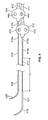
- FIG. 7 is a side view illustration of one embodiment of a lead delivery catheter used to implant a needleless electrical stimulation lead using the natural orifice transluminal endoscopic surgery (NOTES) technique; and,
- FIG. 8 is a flowchart illustrating one embodiment of the steps involved in implanting a needleless electrical stimulation lead using an endoscope.
- the present specification discloses an implantable electrical stimulation lead that is dimensioned specifically for use in confined anatomy, particularly the area proximate the gastroesophageal junction (GEJ).
- the lead is designed to be implanted laparoscopically and includes needles for suturing anchoring elements to the neighboring anatomy.
- the present specification also discloses another, needleless implantable electrical stimulation lead that is designed to be implanted through the working channel of an endoscope and includes anchoring elements that eliminate the need for suturing the lead to surrounding tissues.
- the present specification also discloses a lead delivery catheter used for implanting the needleless electrical stimulation lead through the working channel of an endoscope.
- the present invention is directed toward multiple embodiments. The following disclosure is provided in order to enable a person having ordinary skill in the art to practice the invention.
- an implantable electrical stimulation lead is a bipolar lead and comprises an elongate lead body having a proximal end and a distal end.
- the lead body is comprised of an electrically conductive material with an overlaying insulating sheath. Attached to the proximal end is a coupling means for connecting the lead to a pulse generator such that the two are in electrical communication.
- the coupling means is an international standard (IS-1) connector system.
- the distal end of the lead body includes a bifurcation sleeve.
- the electrically conductive material of the lead body includes an inner coil and an outer coil, electrically insulated from each other, which split into separate branches within the bifurcation sleeve.
- first and second monopolar branches comprise first and second elongate branch bodies respectively, each having a proximal end and a distal end.
- first branch body of the first monopolar branch comprises the continuation of the inner coil of the lead body and the second branch body of the second monopolar branch comprises a partial continuation of the outer coil of lead body attached to an additional coil.
- the additional coil is an elongate coil having a proximal end and a distal end with its proximal end attached to the distal end of the outer coil.
- first branch body of the first monopolar branch comprises the continuation of the inner coil of the lead body and the second branch body of the second monopolar branch comprises the continuation of the outer coil of lead body.
- the proximal ends of the first and second branch bodies join together within the bifurcation sleeve as described above.
- the distal ends of the first and second branch bodies each have a length of suturing material attached to them.
- the suture is a monofilament using nylon as the material. Attached to the distal end of each length of suturing material is a needle.
- the needle is a curved needle.
- the needle is a straight needle.
- Both the first and second branch bodies additionally include at least one anchor and at least one electrode.
- Each electrode is in electrical communication with either the inner or outer coil of its respective branch body.
- the anchor has a butterfly shape with two holes, one on each side, for passing the needle and suture material during anchoring. Each electrode is positioned just distal to each anchor.
- the first monopolar branch has a length that is longer than that of the second monopolar branch. In another embodiment, the first and second monopolar branches have the same length.
- each electrode is insulated by a length of tubing.
- the tubing extends distally from the distal end of the anchoring element.
- the tubing and anchoring element are composed of silicone.
- the lead is designed to be implanted using a standard laparoscopic technique common in the prior art.
- an implantable electrical stimulation lead is intended for implantation via the working channel of an endoscope and includes anchoring elements rather than a needle and sutures for anchoring.
- the implantable electrical stimulation lead is a bipolar lead and also comprises an elongate lead body having a proximal end and a distal end.
- the lead body is comprised of an electrically conductive material with an overlaying insulating sheath. Attached to the proximal end is a coupling means for connecting the lead to a pulse generator such that the two are in electrical communication.
- the coupling means is an IS-1 connector system.
- the distal end of the lead body includes a bifurcation sleeve.
- the electrically conductive material of the lead body includes an inner coil and an outer coil, electrically insulated from each other, which split into separate branches within the bifurcation sleeve.
- first and second monopolar branches comprise first and second elongate branch bodies respectively, each having a proximal end and a distal end.
- first branch body of the first monopolar branch comprises the continuation of the inner coil of the lead body and the second branch body of the second monopolar branch comprises a partial continuation of the outer coil of lead body attached to an additional coil.
- the additional coil is an elongate coil having a proximal end and a distal end with its proximal end attached to the distal end of the outer coil.
- first branch body of the first monopolar branch comprises the continuation of the inner coil of the lead body and the second branch body of the second monopolar branch comprises the continuation of the outer coil of lead body.
- the proximal ends of the first and second branch bodies join together within the bifurcation sleeve as described above.
- the distal ends of the first and second branch bodies are connected by a suture loop.
- the suture loop is designed to be grasped with endoscopic graspers and pulled through the working channel of the endoscope.
- the material of the suture loop is silk.
- Both the first and second branch bodies additionally include at least one anchoring element and at least one electrode. Each electrode is in electrical communication with either the inner or outer coil of its respective branch body.
- the anchoring elements allow for fibrosis around them in the created endoscopic tunnel so that the electrodes remain in position. This eliminates the need for suturing the lead branches in place.
- the anchoring element is a silicone sleeve having grooves, spikes, or holes to allow for the ingrowth of fibrous tissue and anchoring.
- the anchoring element is comprised of a porous material that allows fibrous ingrowth and anchoring.
- the porous material is a Dacron mesh.
- the anchoring material is made of an electrically conductive material, such as platinum-iridium alloy, and is electrically connected to the electrode to increase the area of stimulation.
- the electrodes are the anchors, with special shapes, such as barbs, to facilitate anchoring and tissue in-growth.
- Each electrode is positioned just distal to each anchor.
- the first monopolar branch has a length that is longer than that of the second monopolar branch such that the electrodes are staggered in an in-line position.
- the first and second monopolar branches have the same length.
- the catheter is used with the natural orifice transluminal endoscopic surgery (NOTES) technique to implant one or more leads proximate the lower esophageal sphincter (LES) using an endoscopic approach or a laparoscopic approach.
- NOTES natural orifice transluminal endoscopic surgery
- the catheter includes a catheter body having a proximal end, a distal end, and a lumen within.
- the catheter includes an inflatable balloon, a grasping mechanism, and a light source at its distal end.
- the catheter includes a camera at its distal end.
- the catheter includes a bipolar electrode at its distal end for electrocautery.
- FIGS. 1A and 1B are side and oblique side view illustrations respectively, of one embodiment of an implantable electrical stimulation lead 100 of the present specification.
- the lead 100 is a bipolar lead and includes an elongate lead body 105 having a proximal end and a distal end.
- the lead body 105 is comprised of an electrically conductive inner coil and an electrically conductive outer coil.
- the inner coil and outer coil are each covered by an insulating sheath.
- An IS-1 connector system 107 having proximal and distal ends, is attached to the proximal end of the lead body 105 and a bifurcation sleeve 109 , having proximal and distal ends, is coupled to the distal end of the lead body 105 .
- the length of the lead body 105 is in a range of 390 mm to 490 mm. In one embodiment, the length of the lead body 105 , from the proximal end of the IS-1 connector pin 107 to the distal end of the bifurcation sleeve 109 , is 433 mm. This length is greater than that encountered in the prior art, which often measures approximately 350 mm. The greater length allows for greater variation in implantation site.
- a physician can implant the lead from a more cosmetically pleasing position, for example, a sub-bikini line implantation site or a transumbilical implantation site.
- the resulting stimulator implant scar would not be visible on the patient's abdomen.
- the greater length allows for appropriate routing of the lead to prevent entanglement in the small bowel or a gravid uterus in a female with child bearing potential.
- the inner and outer coils of the lead body 105 separate within the bifurcation sleeve 109 and continue distally as monopolar branches. Referring to FIGS. 1A and 1B , the inner coil continues distally from the distal end of the bifurcation sleeve 109 as a first monopolar branch 111 , having proximal and distal ends, and the outer coil continues distally from the distal end of the bifurcation sleeve 109 and attaches to an additional coil 110 having proximal and distal ends, which continues as a second monopolar branch 112 having proximal and distal ends.
- the outer coil continues distally from the distal end of the bifurcation sleeve 109 as the second monopolar branch 112 having proximal and distal ends.
- the first monopolar branch 111 comprises the inner coil with a covering insulating sheath and includes an anchor 113 , having a proximal end and a distal end, and an insulated electrode 115 , having a proximal end and a distal end, at a point proximate its distal end.
- the electrode 115 is positioned just distal to the anchor 113 .
- Attached to the distal end of the first monopolar branch 111 is a length of suture material 117 , itself having a proximal end and a distal end.
- the suture material is composed of nylon. Attached to the distal end of the suture material is a suture needle 119 .
- the second monopolar branch 112 comprises a portion of the outer coil and an attached additional coil 110 with a covering insulating sheath and includes an anchor 114 , having a proximal end and a distal end, and an insulated electrode 116 , having a proximal end and a distal end, at a point proximate its distal end.
- the electrode 116 is positioned just distal to the anchor 114 .
- Attached to the distal end of the second monopolar branch 112 is a length of suture material 118 , itself having a proximal end and a distal end.
- the suture material is composed of nylon. Attached to the distal end of the suture material is a suture needle 120 .
- each branch includes an additional suture with needle and the anchor, in a butterfly shape, is positioned just distal to the bifurcation sleeve.
- the additional suture and position of the anchor will help maintain the anchor flat on the esophagus after implantation. This will prevent the anchor from pivoting and avoid extra pressure on the esophageal wall.
- FIG. 1A also includes a close-up view illustration of the insulated electrode 115 of the first monopolar branch 111 .
- the electrode 115 includes a covering length of insulating material which will be discussed further with reference to FIG. 3 below. In another embodiment, the electrode is not covered by any insulating material.
- FIG. 2 is a close-up view illustration of the first 211 and second 212 monopolar branches of the embodiment of the implantable electrical stimulation lead of FIG. 1A .
- the monopolar branches 211 , 212 are depicted emanating distally from the distal end of the bifurcation sleeve 209 . Also depicted is the distal end of the lead body 205 coupled to the bifurcation sleeve 209 .
- the first monopolar branch 211 includes an anchor 213 and an insulated electrode 215 at a point proximate its distal end and the second monopolar branch 212 includes an anchor 214 and an insulated electrode 216 at a point proximate its distal end.
- the length l 1 of the first monopolar branch 211 is in a range of 50 mm to 120 mm. In one embodiment, the length l 1 of the first monopolar branch 211 , from its proximal end where it exits the distal end of the bifurcation sleeve 209 to its distal end where it meets the proximal end of the anchor 213 , is 70 mm. This is shorter than the length encountered in the prior art, which is approximately 90 mm.
- the length l 2 of the second monopolar branch 212 is in a range of 50 mm to 120 mm. In one embodiment, the length l 2 of the second monopolar branch 212 , from its proximal end where it exits the distal end of the bifurcation sleeve 209 to its distal end where it meets the proximal end of the anchor 214 , is 60 mm. This is shorter than the length encountered in the prior art, which is approximately 90 mm.
- the first monopolar branch 211 further includes a visual indicator 231 at its distal end, just proximal to the anchor 213 .
- the visual indicator 231 indicates to the physician that this lead contains the inner coil of the lead body.
- the visual indicator 231 is a black marking on the insulation of the first monopolar branch 211 . Having monopolar branches of different lengths allows the physician to implant the electrodes in-line with each other.
- FIG. 3 is a close-up view illustration of the anchors 313 , 314 and insulated proximal portions of the electrodes 315 b , 316 b of the monopolar branches 311 , 312 of the embodiment of the implantable electrical stimulation lead of FIG. 1A .
- the electrode of the first monopolar branch 311 comprises an exposed portion 315 a and an insulated, unexposed portion 315 b that is covered by a length of insulating tubing.
- the length l 3 of the insulating tubing covering the insulated portion of the electrode 315 b is in a range of 1 mm to 5 mm.
- the length l 3 of the insulating tubing covering the insulated portion of the electrode 315 b is 3 mm.
- the insulating tubing is attached to the distal end of the anchor 313 . Depicted attached to the distal end of the exposed portion of the electrode 315 a is the proximal end of a length of suture material 319 .
- the electrode of the first monopolar branch does not include any insulating tubing and is exposed along its entire length (not shown).
- the electrode of the second monopolar branch 312 comprises an exposed portion 316 a and an insulated, unexposed portion 316 b that is covered by a length of insulating tubing.
- the length of the insulating tubing covering the insulated portion of the electrode 316 b of the second monopolar branch 312 is the same as the length of the insulating tubing covering the insulated portion of the electrode 315 b of the lead of the first monopolar branch 311 , that is, in a range of 1 mm to 5 mm.
- the length of the insulating tubing covering the insulated portion of the electrode 316 b of the second monopolar branch 312 is the same as the length of the insulating tubing covering the insulated portion of the electrode 315 b of the lead of the first monopolar branch 311 , that is, 3 mm.
- the insulating tubing covering the insulated portion of the electrode 316 b is attached to the distal end of the anchor 314 . Depicted attached to the distal end of the exposed portion of the electrode 316 a is the proximal end of a length of suture material 318 .
- the electrode of the second monopolar branch does not include any insulating tubing and is exposed along its entire length (not shown).
- the insulating tubing covering the insulated, unexposed portions of the electrodes 315 b , 316 b serve to prevent the exposure of the proximal 2 to 3 mm of each electrode that often occurs during anchoring as the electrodes are pulled backward slightly over time.
- the insulating tubing covering the insulated portions of the electrodes 315 b , 316 b is composed of silicone.
- the wall thickness of the insulating tubing is in a range of 0.160 mm to 0.170 mm. In one embodiment, the wall thickness of the insulating tubing is 0.165 mm (0.0065 in).
- the anchors 313 , 314 are composed of silicone.
- the electrodes are composed of platinum-iridium (Pt—Ir).
- the exposed portion of the electrodes 315 a , 316 a after anchoring, is in a range of 1 mm to 10 mm.
- the exposed portion of the electrodes 315 a , 316 a , after anchoring, is 5 mm. This length is shorter than the average of approximately 10 mm encountered in the prior art. The shorter electrodes have a higher charge density which has been shown to contribute to better results.
- FIG. 4 is a close-up view illustration of the lengths of suture material 417 , 418 attached to the distal ends of the monopolar branches 411 , 412 of the embodiment of the implantable electrical stimulation lead of FIG. 1A . Also depicted are the anchors 413 , 414 , exposed electrode portions 415 a , 415 b , and insulating tubing covering the insulated portions of the electrodes 415 b , 416 b of the first 411 and second 412 monopolar branches. Attached to the distal end of the first monopolar branch 411 and extending distally from the exposed portion of electrode 415 a is a first length of suture material 417 .
- the length of suture material 417 includes a proximal end and a distal end.
- a suture needle 419 is attached to the distal end of the suture material 417 via a coupling means 421 .
- the length l 4 of the suture material 417 is in a range of 55 mm to 65 mm. In one embodiment, the length l 4 of the suture material 417 is 60 mm.
- the length of suture material 418 includes a proximal end and a distal end.
- a suture needle 420 is attached to the distal end of the suture material 418 via a coupling means 422 .
- the length of the suture material 418 attached to the distal end of the second monopolar branch 412 is the same as the length of the suture material 417 attached to the distal end of the first monopolar branch 411 , that is, in a range of 55 mm to 65 mm.
- the length of the suture material 418 attached to the distal end of the second monopolar branch 412 is the same as the length of the suture material 417 attached to the distal end of the first monopolar branch 411 , that is, 60 mm.
- the average length of the suture material encountered in leads in the prior art is approximately 112 mm.
- such a length requires the physician to perform additional, unnecessary pulling maneuvers in order to properly position the anchors.
- the area to maneuver proximate the GEJ is limited by the proximity of the GEJ to the diaphragm. Therefore, a lead with shorter lengths of suture material is advantageous for such an application.
- the suture material is composed of nylon.
- the suture material is barbed, such as V-LocTM by Covidien, to improve anchoring of the electrodes.
- a physician sutures the branches into position by threading the needles 419 , 420 through holes 433 , 444 in the anchors 413 , 414 and into the surrounding tissue.
- the anchors 413 , 414 have a butterfly shape with two holes 433 , 444 positioned on either side of each monopolar branch 411 , 412 .
- FIG. 5 is a close-up view illustration of the needle 500 used to suture in place the anchors of the embodiment of the implantable electrical stimulation lead of FIG. 1A .
- a needle 500 is attached to the distal end of each length of suture material emanating from the distal end of each monopolar branch.
- each needle 500 is attached to the distal end of the suture material via a coupling means.
- each needle 500 is a 3 ⁇ 8 of a circle curve needle and has a length within a range of 18 to 23 mm.
- each needle 500 is a 1 ⁇ 4 of a circle curve needle and has a length within a range of 18 to 23 mm.
- the needle 500 has a tapered point and is a non-cutting needle.
- the needle has a diameter d at its base in a range of 0.68 mm to 0.78 mm, being at least as large as the diameter of the insulated or non-insulated electrode. In one embodiment, the needle has a diameter d at its base of 0.73 mm (0.029 in), which is 0.56 mm (0.022 in) larger than the insulating tubing of the electrode.
- the electrode tract should be straight.
- Traditional 1 ⁇ 2 curve sky shaped or ski needles encountered in the prior art start with a tight bend and hence require a circular maneuver. With such a needle, when a straight bite is attempted, the tissue is often heavily injured, similar to what occurs with a biopsy.
- the needle of the present embodiment having a shorter curve, can be more easily straightened when maneuvering near the GEJ when compared to the needles of the prior art.
- suturing needles and leads encountered in the prior art often include a suture sleeve. Such sleeves tend to attract fibrosis.
- the lead of the present specification does not include a sleeve so as to minimize fibrosis.
- FIG. 6 is a side view illustration of another embodiment of an implantable electrical stimulation lead 600 , depicting a length of suture material 650 joining the distal ends of the two monopolar branches 611 , 612 .
- the lead 600 is a bipolar lead and includes an elongate lead body 605 having a proximal end and a distal end.
- the lead body 605 is comprised of an electrically conductive inner coil and an electrically conductive outer coil.
- the outer coil is covered by an insulating sheath.
- An IS-1 connector system 607 having proximal and distal ends, is attached to the proximal end of the lead body 605 and a bifurcation sleeve 609 , having proximal and distal ends, is coupled to the distal end of the lead body 605 .
- the length l 5 of the lead body 605 from the proximal end of the IS-1 connector system 607 to the distal end of the bifurcation sleeve 609 , is in a range of 390 mm to 490 mm.
- the length l 5 of the lead body 605 from the proximal end of the IS-1 connector system 607 to the distal end of the bifurcation sleeve 609 , is 433 mm.
- the inner and outer coils of the lead body 605 separate within the bifurcation sleeve 609 and continue distally as monopolar branches.
- the inner coil continues distally from the distal end of the bifurcation sleeve 609 as a first monopolar branch 611 , having proximal and distal ends, and a portion of the outer coil continues distally from the distal end of the bifurcation sleeve 609 and attaches to an additional coil 610 , having proximal and distal ends, which continues as a second monopolar branch 612 having proximal and distal ends.
- the outer coil continues distally from the distal end of the bifurcation sleeve 609 as the second monopolar branch 612 having proximal and distal ends.
- the first monopolar branch 611 comprises the inner coil with a covering insulating sheath and includes an anchor 613 , having a proximal end and a distal end, and an electrode 615 , having a proximal end and a distal end, at a point proximate its distal end.
- the electrode 615 is positioned just distal to the anchor 613 .
- the second monopolar branch 612 comprises a portion of the outer coil and an attached additional coil 610 with a covering insulating sheath and includes an anchor 614 , having a proximal end and a distal end, and an electrode 616 , having a proximal end and a distal end, at a point proximate its distal end.
- the electrode 616 is positioned just distal to the anchor 614 .
- the length l 6 of the first monopolar branch 611 from its proximal end where it exits the distal end of the bifurcation sleeve 609 to its distal end where it meets the proximal end of the anchor 613 , is in a range of 50 mm to 120 mm.
- the length l 6 of the first monopolar branch 611 from its proximal end where it exits the distal end of the bifurcation sleeve 609 to its distal end where it meets the proximal end of the anchor 613 , is 70 mm.
- the length l 7 of the second monopolar branch 612 from its proximal end where it exits the distal end of the bifurcation sleeve 609 to its distal end where it meets the proximal end of the anchor 614 , is in a range of 50 mm to 120 mm.
- the length l 7 of the second monopolar branch 612 from its proximal end where it exits the distal end of the bifurcation sleeve 609 to its distal end where it meets the proximal end of the anchor 614 , is 60 mm.
- the length of the electrodes 615 , 616 is in a range of 1 mm to 10 mm. In one embodiment, the length of the electrodes 615 , 616 is 5 mm.
- the different lengths of the first and second monopolar branches allow the electrodes to be positioned in a staggered, in-line configuration. In various embodiments, after anchoring, the electrodes are positioned in a range of 1 to 20 mm apart from one another. In one embodiment, after anchoring, the electrodes are positioned 10 mm apart from one another.
- a length of suture material 650 joins the two monopolar branches 611 , 612 .
- the first end of the length of suture material 650 is attached to the distal end of the first monopolar branch 611 , just distal to the electrode 615
- the second end of the length of suture material 650 is attached to the distal end of the second monopolar branch 612 , just distal to the electrode 616 .
- the suture material 650 acts as a loop to direct the lead 600 during implantation.
- the suture material has a length of 10 to 150 mm.
- the suture material has a length of 60 mm.
- the suture material 650 is composed of nylon.
- the total length of the lead 600 from the proximal end of the IS-1 connector system 607 to the proximal end of the electrode 615 of the first monopolar branch 611 is in a range of 500 mm to 540 mm. In one embodiment, the total length of the lead 600 from the proximal end of the IS-1 connector system 607 to the proximal end of the electrode 615 of the first monopolar branch 611 is 520 mm.
- the implantable electrical implantation lead 600 is designed to be implanted through the working channel of an endoscope.
- a physician inserts an endoscope into a patient using natural orifice transluminal endoscopic surgery (NOTES).
- NOTES a physician passes an endoscope through a natural orifice in the patient's body, such as, the mouth, urethra, or anus, creates an incision in the wall of an internal organ, such as, the stomach, bladder, or colon, and then passes the endoscope through the incision and into the target area or lumen of the organ.
- NOTES natural orifice transluminal endoscopic surgery
- the physician uses endoscopic graspers to grasp the suture material 650 of the lead 600 and then pulls the lead 600 through the working channel of the endoscope.
- the lead could be passed through a working channel of a laparoscopic and pulled through the endoscopic tunnel proximate to the target tissue thus eliminating the need to dissect to expose the target tissue.
- the monopolar branches 611 , 612 are then positioned proximate the target anatomy.
- the anchors 613 , 614 are designed to allow for fibrosis around the implantation site in the endoscopic tunnel, thereby holding the electrodes 615 , 616 in place and eliminating the need for needles and sutures.
- the anchors 613 , 614 comprise sleeves having grooves, spikes, or holes to allow for the ingrowth of fibrous tissue and resultant anchoring.
- the anchors are narrow plastic strips having a plurality of openings for tissue ingrowth.
- the anchors are porous silicone with a plurality of openings for tissue ingrowth and neovascularization.
- the anchors are rosette-shaped and include a plurality of openings for tissue ingrowth.
- the anchors are configured to be wide enough to perform as stoppers but are sufficiently fluffy (porous) to prevent erosion through the esophageal wall.
- the anchors are comprised of silicone.
- the anchors 613 , 614 are composed of a porous material that promotes fibrosis and anchoring.
- the anchors are comprised of a Dacron mesh.
- FIG. 7 is a side view illustration of one embodiment of a lead delivery catheter 700 used to implant the needleless electrical stimulation lead described above using the natural orifice transluminal endoscopic surgery (NOTES) technique.
- the catheter 700 includes a catheter body 711 having a proximal end, a distal end, and a lumen within.
- the catheter 700 has an inflatable balloon 712 attached to its distal end.
- the inflatable balloon 712 is used to perform blunt dissection during implantation.
- the catheter 700 also includes a grasping mechanism 713 at its distal end for grasping the lead.
- the grasping mechanism 713 comprises a pair of opposing grasping members having teeth for grasping the suture loop of the lead.
- the catheter 700 also includes a light source 714 at its distal end for illumination of the implantation area.
- the light source 714 illuminates the implantation tunnel created using the catheter 700 .
- the catheter 700 further includes a camera 715 at its distal end for visualization of the implantation area.
- the light source 714 illuminates the tunnel so that it can be visualized using the camera 715 .
- the catheter 700 further includes a bipolar electrode 716 for electrocautery of tissues as the implantation site.
- the bipolar electrode 716 is incorporated into the grasping mechanism 713 . The bipolar electrode 716 is used to create a primary incision, for dissection in the implantation tunnel, and/or for hemostasis during the implantation procedure.
- the lead delivery catheter 700 can be used to implant one or more leads via the NOTES technique using an endoscopic approach or a laparoscopic approach.
- an incision is made with the catheter tip in the esophageal wall at least one inch proximal to the LES using an endoscopic approach.
- an incision is made with the catheter tip in the gastric wall at least one inch distal to the LES.
- the distal end of the catheter is then advanced through the incision. Air is then pumped through the catheter lumen to inflate the balloon attached to the distal end of the catheter.
- the inflated balloon is used to create a submucosal or subserosal pocket using blunt dissection.
- the distal end of the catheter is then further advanced into the pocket and the balloon is deflated and re-inflated to extend the pocket longitudinally, creating a tunnel for the passage of the lead.
- a second incision is made on the contralateral side to create an exit through the gastrointestinal wall.
- a laparoscopic trocar is inserted into the abdomen with its distal end passing through the second incision.
- the catheter is advanced further and the lead is passed through the laparoscopic trocar, grasped by the grasping mechanism, and pulled into the created tunnel.
- the lead is then positioned proximate the LES.
- the lead can also be passed through an abdominal incision directly and grasped using the grasping mechanism of the catheter.
- the lead and the endoscope with the catheter are withdrawn into the tunnel and the lead is released once the electrodes are in the desired position proximate to the LES muscles.
- the catheter is removed from the endoscope.
- the lead is then passed through a working channel of the endoscope.
- the catheter is reinserted through a laparoscopic trocar and advanced to the implant site.
- the physician grabs the lead which is then positioned proximate the LES.
- fibrosis about the anchors permanently fixes the lead in the tunnel with the stimulating electrodes proximate the LES.
- temporary sutures or clips are used to provide temporary anchoring support while fibrosis is setting in about the anchors. The temporary sutures or clips are later removed after permanent anchoring has been achieved with the lead anchors.
- the lead is delivered to the implantation site using a laparoscopic method with tunneling from the outside inwards.
- This implantation is performed completely laparoscopically without the need for an opening at the distal end of the implantation tunnel.
- the physician laparoscopically creates a dead-end tunnel proximate the target tissues.
- the lead is then pushed into the blind tunnel and allowed to anchor over time.
- the lead is delivered to the implantation site via a completely endoscopic procedure.
- the physician creates a tunnel as described above.
- the lead is passed through the endoscope and placed into position using the grasping mechanism of the catheter.
- FIG. 8 is a flowchart illustrating one embodiment of the steps involved in implanting the needleless electrical stimulation lead using an endoscope.
- the lead is of the type having the suture material loop as described with reference to FIG. 6 above.
- a physician inserts an endoscope into the mouth of a patient with lower esophageal sphincter (LES) dysfunction.
- a lead delivery catheter as described with reference to FIG. 7 is also inserted into a working channel of the endoscope.
- an incision is made in the wall of the lower esophagus. The distal end of the catheter is then advanced through the incision and into an area proximate the GEJ at step 806 .
- the balloon at the distal end of the catheter is inflated and used to create an implantation tunnel using blunt dissection.
- the lead is pulled by endoscopic graspers through a laparoscope that has been inserted into the patient's abdomen to the tunnel created proximate the GEJ.
- the monopolar branches of the lead are then positioned with the electrodes proximate the LES at step 812 .
- the IS-1 connector at the other end of the lead is attached to a pulse generator. Over time, at step 816 , fibrous tissue grows into the anchor, fixing the lead in place.
Abstract
Description
Claims (15)
Priority Applications (3)
| Application Number | Priority Date | Filing Date | Title |
|---|---|---|---|
| US14/191,085 US9498619B2 (en) | 2013-02-26 | 2014-02-26 | Implantable electrical stimulation leads |
| US14/753,402 US20150297885A1 (en) | 2013-02-26 | 2015-06-29 | Implantable Electrical Stimulation Leads |
| US15/296,604 US20170128716A1 (en) | 2013-02-26 | 2016-10-18 | Implantable Electrical Stimulation Leads |
Applications Claiming Priority (2)
| Application Number | Priority Date | Filing Date | Title |
|---|---|---|---|
| US201361769732P | 2013-02-26 | 2013-02-26 | |
| US14/191,085 US9498619B2 (en) | 2013-02-26 | 2014-02-26 | Implantable electrical stimulation leads |
Related Child Applications (2)
| Application Number | Title | Priority Date | Filing Date |
|---|---|---|---|
| US14/753,402 Continuation-In-Part US20150297885A1 (en) | 2013-02-26 | 2015-06-29 | Implantable Electrical Stimulation Leads |
| US15/296,604 Continuation US20170128716A1 (en) | 2013-02-26 | 2016-10-18 | Implantable Electrical Stimulation Leads |
Publications (2)
| Publication Number | Publication Date |
|---|---|
| US20140243593A1 US20140243593A1 (en) | 2014-08-28 |
| US9498619B2 true US9498619B2 (en) | 2016-11-22 |
Family
ID=51388811
Family Applications (2)
| Application Number | Title | Priority Date | Filing Date |
|---|---|---|---|
| US14/191,085 Active - Reinstated 2034-09-19 US9498619B2 (en) | 2013-02-26 | 2014-02-26 | Implantable electrical stimulation leads |
| US15/296,604 Abandoned US20170128716A1 (en) | 2013-02-26 | 2016-10-18 | Implantable Electrical Stimulation Leads |
Family Applications After (1)
| Application Number | Title | Priority Date | Filing Date |
|---|---|---|---|
| US15/296,604 Abandoned US20170128716A1 (en) | 2013-02-26 | 2016-10-18 | Implantable Electrical Stimulation Leads |
Country Status (1)
| Country | Link |
|---|---|
| US (2) | US9498619B2 (en) |
Cited By (15)
| Publication number | Priority date | Publication date | Assignee | Title |
|---|---|---|---|---|
| US20150119646A1 (en) * | 2011-09-02 | 2015-04-30 | Endostim, Inc. | Lead Implantation Method |
| WO2017123529A1 (en) * | 2016-01-13 | 2017-07-20 | Kessler Foundation Inc. | Neuromuscular stimulation system and method |
| US10058703B2 (en) | 2010-03-05 | 2018-08-28 | Endostim, Inc. | Methods of treating gastroesophageal reflux disease using an implanted device |
| US10272242B2 (en) | 2006-05-18 | 2019-04-30 | Endostim, Inc. | Device and implantation system for electrical stimulation of biological systems |
| US10376694B2 (en) | 2008-10-09 | 2019-08-13 | Virender K. Sharma | Method and apparatus for stimulating the vascular system |
| US10406356B2 (en) | 2006-10-09 | 2019-09-10 | Endostim, Inc. | Systems and methods for electrical stimulation of biological systems |
| US10426955B2 (en) | 2006-10-09 | 2019-10-01 | Endostim, Inc. | Methods for implanting electrodes and treating a patient with gastreosophageal reflux disease |
| US10603489B2 (en) | 2008-10-09 | 2020-03-31 | Virender K. Sharma | Methods and apparatuses for stimulating blood vessels in order to control, treat, and/or prevent a hemorrhage |
| US11052254B2 (en) | 2013-09-03 | 2021-07-06 | Endostim (Abc), Llc | Methods and systems of electrode polarity switching in electrical stimulation therapy |
| US11052248B2 (en) | 2012-08-23 | 2021-07-06 | Endostim (Abc), Llc | Device and implantation system for electrical stimulation of biological systems |
| US11058876B2 (en) | 2010-03-05 | 2021-07-13 | Endostim (Abc), Llc | Device and implantation system for electrical stimulation of biological systems |
| US11577077B2 (en) | 2006-10-09 | 2023-02-14 | Endostim, Inc. | Systems and methods for electrical stimulation of biological systems |
| US11717681B2 (en) | 2010-03-05 | 2023-08-08 | Endostim, Inc. | Systems and methods for treating gastroesophageal reflux disease |
| US11786726B2 (en) | 2006-10-09 | 2023-10-17 | Endostim, Inc. | Device and implantation system for electrical stimulation of biological systems |
| US11819683B2 (en) | 2016-11-17 | 2023-11-21 | Endostim, Inc. | Modular stimulation system for the treatment of gastrointestinal disorders |
Families Citing this family (15)
| Publication number | Priority date | Publication date | Assignee | Title |
|---|---|---|---|---|
| US9782583B2 (en) | 2012-02-21 | 2017-10-10 | Virender K. Sharma | System and method for electrical stimulation of anorectal structures to treat urinary dysfunction |
| US8706234B2 (en) | 2012-02-21 | 2014-04-22 | Virender K. Sharma | System and method for electrical stimulation of anorectal structures to treat anal dysfunction |
| US10576278B2 (en) | 2012-02-21 | 2020-03-03 | Virender K. Sharma | System and method for electrical stimulation of anorectal structures to treat urinary dysfunction |
| US9498619B2 (en) | 2013-02-26 | 2016-11-22 | Endostim, Inc. | Implantable electrical stimulation leads |
| US9511230B2 (en) | 2013-11-08 | 2016-12-06 | Nuvectra Corporation | Implantable medical lead for stimulation of multiple nerves |
| EP3071289A4 (en) * | 2013-11-20 | 2017-05-31 | Endostim, Inc. | Lead implantation method |
| GB201414533D0 (en) * | 2014-08-15 | 2014-10-01 | Asalus Medical Instr Ltd | Laparoscopic access port |
| US9682234B2 (en) | 2014-11-17 | 2017-06-20 | Endostim, Inc. | Implantable electro-medical device programmable for improved operational life |
| EP4223359A1 (en) | 2014-12-09 | 2023-08-09 | Esh, Mordechay | Non-invasive device for treating gastro-esophageal reflux disease |
| CN107206228A (en) * | 2015-01-20 | 2017-09-26 | Med-El电气医疗器械有限公司 | With the cochleostapedial reflex recording electrode for sacrificing part |
| WO2017040752A1 (en) | 2015-09-02 | 2017-03-09 | Cook Medical Technologies Llc | Electrotherapeutic systems, devices, and methods |
| EP3606603A1 (en) * | 2017-04-06 | 2020-02-12 | Endostim, Inc. | Implantable surface electrodes and method of implantation |
| GB2563440B (en) * | 2017-06-16 | 2019-06-05 | Cardiaccs As | Securing a sensor at the heart |
| US11097115B2 (en) * | 2018-09-24 | 2021-08-24 | Galvani Bioelectronics Limited | Implantable pulse generator with suture holes and methods for implanting the same |
| CN113576614B (en) * | 2021-08-02 | 2022-03-15 | 中国医学科学院阜外医院 | Puncturing device for puncturing atrial septal defect patch |
Citations (245)
| Publication number | Priority date | Publication date | Assignee | Title |
|---|---|---|---|---|
| US3910281A (en) | 1973-10-09 | 1975-10-07 | Bio Medicus Inc | Suture anchor |
| US3909883A (en) | 1972-02-28 | 1975-10-07 | Richco Plastic Co | Locking base for plastic components |
| US4393883A (en) * | 1980-11-03 | 1983-07-19 | Medtronic, Inc. | Single pass A-V lead |
| US4414986A (en) | 1982-01-29 | 1983-11-15 | Medtronic, Inc. | Biomedical stimulation lead |
| US4612934A (en) | 1981-06-30 | 1986-09-23 | Borkan William N | Non-invasive multiprogrammable tissue stimulator |
| US4735205A (en) * | 1986-02-24 | 1988-04-05 | Medtronic, Inc. | Method and apparatus including a sliding insulation lead for cardiac assistance |
| US5117827A (en) | 1990-10-26 | 1992-06-02 | Sandhill Scientific, Inc. | Apparatus and method for ambulatory reflux monitoring |
| US5188104A (en) | 1991-02-01 | 1993-02-23 | Cyberonics, Inc. | Treatment of eating disorders by nerve stimulation |
| US5193539A (en) | 1991-12-18 | 1993-03-16 | Alfred E. Mann Foundation For Scientific Research | Implantable microstimulator |
| US5197491A (en) | 1990-09-28 | 1993-03-30 | Brunswick Biomedical Technologies, Inc. | Esophageal-stomach displacement electrode |
| US5231988A (en) | 1991-08-09 | 1993-08-03 | Cyberonics, Inc. | Treatment of endocrine disorders by nerve stimulation |
| US5263480A (en) | 1991-02-01 | 1993-11-23 | Cyberonics, Inc. | Treatment of eating disorders by nerve stimulation |
| US5292344A (en) | 1992-07-10 | 1994-03-08 | Douglas Donald D | Percutaneously placed electrical gastrointestinal pacemaker stimulatory system, sensing system, and pH monitoring system, with optional delivery port |
| US5360428A (en) * | 1992-07-22 | 1994-11-01 | Hutchinson Jr William B | Laparoscopic instrument with electrical cutting wires |
| US5423872A (en) | 1992-05-29 | 1995-06-13 | Cigaina; Valerio | Process and device for treating obesity and syndromes related to motor disorders of the stomach of a patient |
| US5531778A (en) * | 1994-09-20 | 1996-07-02 | Cyberonics, Inc. | Circumneural electrode assembly |
| US5540730A (en) | 1995-06-06 | 1996-07-30 | Cyberonics, Inc. | Treatment of motility disorders by nerve stimulation |
| US5556425A (en) | 1994-11-28 | 1996-09-17 | Brunswick Biomedical Technologies, Inc. | Esophageal/stomach placement electrode |
| US5649902A (en) | 1988-07-22 | 1997-07-22 | Yoon; Inbae | Multifunctional devices for endoscopic surgical procedures |
| US5674205A (en) | 1993-08-26 | 1997-10-07 | The Johns Hopkins University | Device for treating gastrointestinal muscle disorders and other smooth muscle dysfunction |
| US5690691A (en) | 1996-05-08 | 1997-11-25 | The Center For Innovative Technology | Gastro-intestinal pacemaker having phased multi-point stimulation |
| US5697375A (en) | 1989-09-18 | 1997-12-16 | The Research Foundation Of State University Of New York | Method and apparatus utilizing heart sounds for determining pressures associated with the left atrium |
| US5709224A (en) * | 1995-06-07 | 1998-01-20 | Radiotherapeutics Corporation | Method and device for permanent vessel occlusion |
| US5716392A (en) | 1996-01-05 | 1998-02-10 | Medtronic, Inc. | Minimally invasive medical electrical lead |
| US5716385A (en) | 1996-11-12 | 1998-02-10 | University Of Virginia | Crural diaphragm pacemaker and method for treating esophageal reflux disease |
| US5810810A (en) * | 1992-04-23 | 1998-09-22 | Scimed Life Systems, Inc. | Apparatus and method for sealing vascular punctures |
| US5836994A (en) | 1997-04-30 | 1998-11-17 | Medtronic, Inc. | Method and apparatus for electrical stimulation of the gastrointestinal tract |
| WO1998053878A1 (en) | 1997-05-28 | 1998-12-03 | Transneuronix, Inc. | Implant device for electrostimulation and/or monitoring of endo-abdominal cavity tissue |
| US5861014A (en) | 1997-04-30 | 1999-01-19 | Medtronic, Inc. | Method and apparatus for sensing a stimulating gastrointestinal tract on-demand |
| US5861044A (en) | 1995-03-16 | 1999-01-19 | Milliken Research Corporation | Method to selectively carve textile fabrics |
| US5882340A (en) | 1992-04-15 | 1999-03-16 | Yoon; Inbae | Penetrating instrument having an expandable anchoring portion for triggering protrusion of a safety member and/or retraction of a penetrating member |
| WO1999003532A3 (en) | 1997-05-02 | 1999-04-08 | Medtronic Inc | Apparatus for treatment of gastric arrhythmias |
| US5893883A (en) | 1997-04-30 | 1999-04-13 | Medtronic, Inc. | Portable stimulation screening device for screening therapeutic effect of electrical stimulation on a patient user during normal activities of the patient user |
| WO1999030776A1 (en) | 1997-12-15 | 1999-06-24 | Medtronic, Inc. | Method and apparatus for electrical stimulation of the gastrointestinal tract |
| US5935126A (en) | 1994-05-10 | 1999-08-10 | Riza; Erol D. | Surgical instrument with jaws having electrical contacts |
| US6006755A (en) | 1994-06-24 | 1999-12-28 | Edwards; Stuart D. | Method to detect and treat aberrant myoelectric activity |
| US6026326A (en) | 1997-01-13 | 2000-02-15 | Medtronic, Inc. | Apparatus and method for treating chronic constipation |
| US6051017A (en) | 1996-02-20 | 2000-04-18 | Advanced Bionics Corporation | Implantable microstimulator and systems employing the same |
| US6091992A (en) | 1997-12-15 | 2000-07-18 | Medtronic, Inc. | Method and apparatus for electrical stimulation of the gastrointestinal tract |
| US6097984A (en) | 1998-11-25 | 2000-08-01 | Medtronic, Inc. | System and method of stimulation for treating gastro-esophageal reflux disease |
| WO2000061224A1 (en) | 1999-04-14 | 2000-10-19 | Transneuronix, Inc. | Gastric stimulator apparatus and method for installing |
| WO2000061223A1 (en) | 1999-04-14 | 2000-10-19 | Transneuronix, Inc. | Gastric stimulator apparatus and method for use |
| US6221039B1 (en) * | 1998-10-26 | 2001-04-24 | Scimed Life Systems, Inc. | Multi-function surgical instrument |
| US6243607B1 (en) | 1996-09-05 | 2001-06-05 | University Technologies International Inc. | Gastro-intestinal electrical pacemaker |
| US6254598B1 (en) | 1994-06-24 | 2001-07-03 | Curon Medical, Inc. | Sphincter treatment apparatus |
| US6285897B1 (en) | 1999-04-07 | 2001-09-04 | Endonetics, Inc. | Remote physiological monitoring system |
| US20010041831A1 (en) | 2000-01-21 | 2001-11-15 | Starkweather Timothy J. | Ambulatory medical apparatus and method having telemetry modifiable control software |
| US6321124B1 (en) | 1997-05-28 | 2001-11-20 | Transneuronix, Inc. | Implant device for electrostimulation and/or monitoring of endo-abdominal cavity tissue |
| US6360130B1 (en) * | 1998-09-30 | 2002-03-19 | Medtronic, Inc. | Temporary bi-polar heart wire |
| US6381495B1 (en) | 1997-05-28 | 2002-04-30 | Transneuronix, Inc. | Medical device for use in laparoscopic surgery |
| WO2002043467A2 (en) | 2000-11-15 | 2002-06-06 | Transneuronix, Inc. | Improved process for electrostimulation treatment of morbid obesity |
| US20020103522A1 (en) * | 2001-01-31 | 2002-08-01 | Swoyer John M. | Implantable bifurcated gastrointestinal lead with active fixation |
| US20020138075A1 (en) | 1998-02-19 | 2002-09-26 | Curon Medical, Inc. | Method to treat gastric reflux via the detection and ablation of gastro-esophageal nerves and receptors |
| US20020161414A1 (en) | 2000-12-11 | 2002-10-31 | Melina Flesler | Acute and chronic electrical signal therapy for obesity |
| US20020165589A1 (en) | 2001-05-01 | 2002-11-07 | Imran Mir A. | Gastric treatment and diagnosis device and method |
| US20030014086A1 (en) | 2001-07-14 | 2003-01-16 | Sharma Virender K. | Method and apparatus for electrical stimulation of the lower esophageal sphincter |
| US6510332B1 (en) | 1999-08-30 | 2003-01-21 | Transneuronix, Inc. | Electrode leads for use in laparoscopic surgery |
| US20030028226A1 (en) | 1998-06-19 | 2003-02-06 | Medtronic, Inc. | Medical management system integrated programming apparatus for communication with an implantable medical device |
| US20030055463A1 (en) * | 1999-04-14 | 2003-03-20 | Transneuronix, Inc. | Gastric stimulator apparatus and method for installing |
| WO2002089655A3 (en) | 2001-05-01 | 2003-04-17 | Intrapace Inc | Submucosal gastric implant device and method |
| US20030078633A1 (en) | 2001-09-28 | 2003-04-24 | Firlik Andrew D. | Methods and implantable apparatus for electrical therapy |
| US6571127B1 (en) | 1997-07-16 | 2003-05-27 | Impulse Dynamics N.V. | Method of increasing the motility of a GI tract |
| US20030120321A1 (en) | 2001-11-09 | 2003-06-26 | Pulsion Medical Systems Ag | Implantable muscle stimulation device |
| US6587719B1 (en) | 1999-07-01 | 2003-07-01 | Cyberonics, Inc. | Treatment of obesity by bilateral vagus nerve stimulation |
| US6591137B1 (en) | 2000-11-09 | 2003-07-08 | Neuropace, Inc. | Implantable neuromuscular stimulator for the treatment of gastrointestinal disorders |
| US20030144708A1 (en) | 2002-01-29 | 2003-07-31 | Starkebaum Warren L. | Methods and apparatus for retarding stomach emptying for treatment of eating disorders |
| US6611715B1 (en) | 1998-10-26 | 2003-08-26 | Birinder R. Boveja | Apparatus and method for neuromodulation therapy for obesity and compulsive eating disorders using an implantable lead-receiver and an external stimulator |
| US6612983B1 (en) | 2000-03-28 | 2003-09-02 | Medtronic, Inc. | Pancreatic secretion response to stimulation test protocol |
| US20030195600A1 (en) | 2002-04-12 | 2003-10-16 | Carole Tronnes | Implantable medical device with captivation fixation |
| US6678561B2 (en) | 2001-05-23 | 2004-01-13 | Surgical Development Ag | Heartburn and reflux disease treatment apparatus |
| US20040015201A1 (en) | 2002-04-22 | 2004-01-22 | Transneuronix, Inc. | Process for electrostimulation treatment of obesity |
| US20040012088A1 (en) | 1998-02-27 | 2004-01-22 | Fujitsu Limited, | Semiconductor device having a ball grid array and a fabrication process thereof |
| CN1476339A (en) | 2000-09-26 | 2004-02-18 | 特兰施钮罗尼克斯股份有限公司 | Method and apparatus for treating obesity by electrical stimulation of gastrointestinal tract using sensed activity |
| US20040039427A1 (en) | 2001-01-02 | 2004-02-26 | Cyberonics, Inc. | Treatment of obesity by sub-diaphragmatic nerve stimulation |
| US20040059393A1 (en) | 2001-01-05 | 2004-03-25 | Shai Policker | Regulation of eating habits |
| US20040073453A1 (en) | 2002-01-10 | 2004-04-15 | Nenov Valeriy I. | Method and system for dispensing communication devices to provide access to patient-related information |
| US20040088033A1 (en) | 2002-10-31 | 2004-05-06 | Smits Karel F.A.A. | Implantable medical lead designs |
| US6749607B2 (en) | 1998-03-06 | 2004-06-15 | Curon Medical, Inc. | Apparatus to treat esophageal sphincters |
| US20040116977A1 (en) | 2002-12-13 | 2004-06-17 | Finch Philip M. | System and method for electrical stimulation of the intervertebral disc |
| US6754536B2 (en) | 2001-01-31 | 2004-06-22 | Medtronic, Inc | Implantable medical device affixed internally within the gastrointestinal tract |
| US6760626B1 (en) | 2001-08-29 | 2004-07-06 | Birinder R. Boveja | Apparatus and method for treatment of neurological and neuropsychiatric disorders using programmerless implantable pulse generator system |
| US20040138586A1 (en) | 2002-11-20 | 2004-07-15 | Ganz Robert A. | Apparatus and method for determining yield pressure |
| US20040167583A1 (en) | 2003-02-03 | 2004-08-26 | Enteromedics, Inc. | Electrode band apparatus and method |
| US20040186544A1 (en) | 2001-11-07 | 2004-09-23 | Medtronic, Inc. | Electrical tissue stimulation apparatus and method |
| US20040193229A1 (en) | 2002-05-17 | 2004-09-30 | Medtronic, Inc. | Gastric electrical stimulation for treatment of gastro-esophageal reflux disease |
| US6826428B1 (en) | 2000-04-11 | 2004-11-30 | The Board Of Regents Of The University Of Texas System | Gastrointestinal electrical stimulation |
| US20040243182A1 (en) | 2001-08-31 | 2004-12-02 | Ehud Cohen | Treatment of disorders by unidirectional nerve stimulation |
| US6832114B1 (en) | 2000-11-21 | 2004-12-14 | Advanced Bionics Corporation | Systems and methods for modulation of pancreatic endocrine secretion and treatment of diabetes |
| US20050027328A1 (en) | 2000-09-26 | 2005-02-03 | Transneuronix, Inc. | Minimally invasive surgery placement of stimulation leads in mediastinal structures |
| US6853862B1 (en) | 1999-12-03 | 2005-02-08 | Medtronic, Inc. | Gastroelectric stimulation for influencing pancreatic secretions |
| US20050049655A1 (en) | 2003-08-27 | 2005-03-03 | Boveja Birinder R. | System and method for providing electrical pulses to the vagus nerve(s) to provide therapy for obesity, eating disorders, neurological and neuropsychiatric disorders with a stimulator, comprising bi-directional communication and network capabilities |
| US20050065571A1 (en) | 2001-05-01 | 2005-03-24 | Imran Mir A. | Responsive gastric stimulator |
| US20050070974A1 (en) | 2003-09-29 | 2005-03-31 | Knudson Mark B. | Obesity and eating disorder stimulation treatment with neural block |
| US20050075678A1 (en) | 2003-10-07 | 2005-04-07 | John Faul | Transcutaneous electrical nerve stimulator for appetite control |
| US6879861B2 (en) | 2000-12-21 | 2005-04-12 | Medtronic, Inc. | Polymeric materials with improved dielectric breakdown strength |
| US6879859B1 (en) | 1998-10-26 | 2005-04-12 | Birinder R. Boveja | External pulse generator for adjunct (add-on) treatment of obesity, eating disorders, neurological, neuropsychiatric, and urological disorders |
| US20050090873A1 (en) | 2003-10-22 | 2005-04-28 | Imran Mir A. | Gastrointestinal stimulation device |
| WO2005051486A1 (en) | 2003-11-28 | 2005-06-09 | University Technologies International Inc. | Method and apparatus for gastrointestinal motility control |
| US20050131486A1 (en) | 2002-05-09 | 2005-06-16 | Boveja Birinder R. | Method and system for vagal blocking with or without vagal stimulation to provide therapy for obesity and other gastrointestinal disorders using rechargeable implanted pulse generator |
| US20050137480A1 (en) | 2001-10-01 | 2005-06-23 | Eckhard Alt | Remote control of implantable device through medical implant communication service band |
| US20050137644A1 (en) | 1998-10-26 | 2005-06-23 | Boveja Birinder R. | Method and system for vagal blocking and/or vagal stimulation to provide therapy for obesity and other gastrointestinal disorders |
| US6915165B2 (en) | 2001-06-28 | 2005-07-05 | Obtech Medical Ag | Intestine dysfunction treatment apparatus |
| US20050149142A1 (en) | 2004-01-07 | 2005-07-07 | Starkebaum Warren L. | Gastric stimulation responsive to sensing feedback |
| US20050149141A1 (en) | 2004-01-07 | 2005-07-07 | Starkebaum Warren L. | Gastric stimulation for altered perception to treat obesity |
| US6952613B2 (en) | 2001-01-31 | 2005-10-04 | Medtronic, Inc. | Implantable gastrointestinal lead with active fixation |
| US20050222638A1 (en) | 2004-03-30 | 2005-10-06 | Steve Foley | Sensor based gastrointestinal electrical stimulation for the treatment of obesity or motility disorders |
| US20050222637A1 (en) | 2004-03-30 | 2005-10-06 | Transneuronix, Inc. | Tachygastrial electrical stimulation |
| US20050245788A1 (en) | 2004-04-28 | 2005-11-03 | Medtronic, Inc. | Esophageal delivery system and method with position indexing |
| US20050251219A1 (en) | 2004-05-05 | 2005-11-10 | Evans John R | Device and method for placement of electrodes in the GI tract |
| US20060004304A1 (en) | 2004-05-17 | 2006-01-05 | Sierra Scientific Instruments, Inc. | Analysis and visualization methods using manometry data |
| US20060036293A1 (en) | 2004-08-16 | 2006-02-16 | Whitehurst Todd K | Methods for treating gastrointestinal disorders |
| US7006871B1 (en) | 1997-07-16 | 2006-02-28 | Metacure N.V. | Blood glucose level control |
| US20060064037A1 (en) | 2004-09-22 | 2006-03-23 | Shalon Ventures Research, Llc | Systems and methods for monitoring and modifying behavior |
| US20060095077A1 (en) | 2004-10-29 | 2006-05-04 | Tronnes Carole A | Expandable fixation structures |
| US20060106442A1 (en) | 2004-05-19 | 2006-05-18 | The Board Of Trustees Of The Leland Stanford Junior University | Devices and methods for treating cardiac pathologies |
| US7054689B1 (en) | 2000-08-18 | 2006-05-30 | Advanced Bionics Corporation | Fully implantable neurostimulator for autonomic nerve fiber stimulation as a therapy for urinary and bowel dysfunction |
| US20060116736A1 (en) | 2001-07-23 | 2006-06-01 | Dilorenzo Daniel J | Method, apparatus, and surgical technique for autonomic neuromodulation for the treatment of obesity |
| US20060167498A1 (en) | 2001-07-23 | 2006-07-27 | Dilorenzo Daniel J | Method, apparatus, and surgical technique for autonomic neuromodulation for the treatment of disease |
| US7087053B2 (en) | 2004-05-27 | 2006-08-08 | St. Jude Medical, Atrial Fibrillation Division, Inc. | Catheter with bifurcated, collapsible tip for sensing and ablating |
| US20060200217A1 (en) | 2000-09-26 | 2006-09-07 | Wessman Bradley J | Medical lead and method for medical lead manufacture |
| US20060206160A1 (en) | 2000-11-15 | 2006-09-14 | Transneuronix, Inc. | Process and electrostimulation device for treating obesity and/or gastroesophageal reflux disease |
| US20060218011A1 (en) | 1995-11-22 | 2006-09-28 | Walker Jay S | Systems and methods for improved health care compliance |
| US7114502B2 (en) | 1997-02-26 | 2006-10-03 | Alfred E. Mann Foundation For Scientific Research | Battery-powered patient implantable device |
| US20060247718A1 (en) | 2005-04-28 | 2006-11-02 | Medtronic, Inc. | Dual mode electrical stimulation to treat obesity |
| US20060247722A1 (en) | 2005-04-29 | 2006-11-02 | Cyberonics, Inc. | Noninvasively adjustable gastric band |
| US20060247717A1 (en) | 2005-04-28 | 2006-11-02 | Medtronic, Inc. | Electrical stimulation of the gastrointestinal tract to regulate motility |
| US20060265021A1 (en) | 2004-03-16 | 2006-11-23 | Medtronic, Inc. | Intra-Luminal Device for Gastrointestinal Electrical Stimulation |
| US20070016274A1 (en) | 2005-06-29 | 2007-01-18 | Boveja Birinder R | Gastrointestinal (GI) ablation for GI tumors or to provide therapy for obesity, motility disorders, G.E.R.D., or to induce weight loss |
| US20070049793A1 (en) | 2005-08-25 | 2007-03-01 | Ignagni Anthony R | Method And Apparatus For Transgastric Neurostimulation |
| US20070060955A1 (en) | 2004-06-10 | 2007-03-15 | Ndi Medical, Llc | Implantable pulse generator systems and methods for providing functional and/or therapeutic stimulation of muscles and/or nerves and/or central nervous system tissue |
| US20070060968A1 (en) | 2004-06-10 | 2007-03-15 | Ndi Medical, Llc | Implantable pulse generator systems and methods for providing functional and/or therapeutic stimulation of muscles and/or nerves and/or central nervous system tissue |
| US20070060979A1 (en) | 2004-06-10 | 2007-03-15 | Ndi Medical, Llc | Implantable pulse generator systems and methods for providing functional and / or therapeutic stimulation of muscles and / or nerves and / or central nervous system tissue |
| US20070066995A1 (en) | 2004-06-10 | 2007-03-22 | Ndi Medical, Llc | Implantable pulse generator systems and methods for providing functional and/or therapeutic stimulation of muscles and/or nerves and/or central nervous system tissue |
| US20070067000A1 (en) | 2004-06-10 | 2007-03-22 | Ndi Medical, Llc | Implantable pulse generator systems and methods for providing functional and/or therapeutic stimulation of muscles and/or nerves and/or central nervous system tissue |
| US7203551B2 (en) | 2003-04-25 | 2007-04-10 | Medtronic, Inc. | Implantable lead-based sensor powered by piezoelectric transformer |
| US20070100388A1 (en) | 2005-10-31 | 2007-05-03 | Medtronic, Inc. | Implantable medical device providing adaptive neurostimulation therapy for incontinence |
| US20070106338A1 (en) | 2005-11-10 | 2007-05-10 | Electrocore, Inc. | Direct and Indirect Control of Muscle for the Treatment of Pathologies |
| US20070106337A1 (en) | 2005-11-10 | 2007-05-10 | Electrocore, Inc. | Methods And Apparatus For Treating Disorders Through Neurological And/Or Muscular Intervention |
| US20070142884A1 (en) | 2005-12-16 | 2007-06-21 | Acoustx Corporation | Methods and apparatuses for treating an esophageal disorder such as gastroesophageal reflux disease |
| US20070142831A1 (en) | 1998-05-20 | 2007-06-21 | Shadduck John H | Surgical Instruments And Techniques For Treating Gastro-Esophageal Reflux Disease |
| US20070142699A1 (en) | 2005-12-16 | 2007-06-21 | Acoustx Corporation | Methods and implantable apparatuses for treating an esophageal disorder such as gastroesophageal reflux disease |
| US20070156182A1 (en) | 2006-01-04 | 2007-07-05 | Castel J C | Electrical stimulation device and method for the treatment of dysphagia |
| US20070162085A1 (en) | 2001-07-23 | 2007-07-12 | Dilorenzo Biomedical, Llc | Method, apparatus, surgical technique, and stimulation parameters for autonomic neuromodulation for the treatment of obesity |
| US20070162084A1 (en) | 2000-10-11 | 2007-07-12 | Jiande Chen | Gastrointestinal electrical stimulation |
| US20070179542A1 (en) | 2006-01-31 | 2007-08-02 | Rajan Prakash | Method and apparatus for determining optimal pacing therapy timing intervals |
| US20070239248A1 (en) | 2006-03-31 | 2007-10-11 | Hastings Roger N | Cardiac stimulation electrodes, delivery devices, and implantation configurations |
| US20070238942A1 (en) | 2006-04-10 | 2007-10-11 | Esophamet Corp. | Apparatus and method for detecting gastroesophageal reflux disease (gerd) |
| US20070244375A1 (en) | 2004-09-30 | 2007-10-18 | Transeuronix, Inc. | Method for Screening and Treating Patients at Risk of Medical Disorders |
| US20070255352A1 (en) | 2006-04-27 | 2007-11-01 | Roline Glen M | Implantable sensors having current-based switches for improved fault tolerance |
| US20070255336A1 (en) | 2006-04-28 | 2007-11-01 | Medtronic, Inc. | Gastric constriction device with selectable electrode combinations |
| US20070255335A1 (en) | 2006-04-28 | 2007-11-01 | Medtronic, Inc. | Controller for gastric constriction device with selectable electrode configurations |
| US20070255118A1 (en) | 2004-04-14 | 2007-11-01 | Medtronic, Inc. | Collecting posture and activity information to evaluate therapy |
| US20070265666A1 (en) | 2006-04-27 | 2007-11-15 | Roberts Jonathan P | Implantable sensors having high impedance couplings providing current pathways for improved fault tolerance |
| US20070265662A1 (en) | 2006-04-27 | 2007-11-15 | Ufford Keith A | Implantable electromagnetic interference tolerant, wired sensors and methods for implementing same |
| US20070265671A1 (en) | 2006-04-27 | 2007-11-15 | Roberts Jonathan P | Selectable switching of implantable sensors to provide fault toleance for implantable medical devices |
| US20070265674A1 (en) | 2006-04-27 | 2007-11-15 | Olson John C | Fault tolerant implantable sensors having redundant electrical grounding connections |
| US20070265668A1 (en) | 2006-04-27 | 2007-11-15 | Reinke James D | Fault tolerant sensors and methods for implementing fault tolerance in implantable medical devices |
| WO2007137026A2 (en) | 2006-05-18 | 2007-11-29 | Cedars-Sinai Medical Center | Electrical stimulation of the lower esophageal sphincter |
| US20070282410A1 (en) | 2006-04-28 | 2007-12-06 | Cross Thomas E Jr | Implantable medical lead assemblies with improved flexibility and extensibility and having a substantially two-dimensional nature |
| US7310557B2 (en) | 2005-04-29 | 2007-12-18 | Maschino Steven E | Identification of electrodes for nerve stimulation in the treatment of eating disorders |
| US20080021512A1 (en) | 2003-02-03 | 2008-01-24 | Enteromedics Inc. | Nerve stimulation and blocking for treatment of gastrointestinal disorders |
| US20080039904A1 (en) | 2006-08-08 | 2008-02-14 | Cherik Bulkes | Intravascular implant system |
| US20080046062A1 (en) * | 2006-08-03 | 2008-02-21 | Medtronic, Inc. | Implantable medical lead with proximal retrieval wire |
| US20080058836A1 (en) * | 2006-08-03 | 2008-03-06 | Hansen Medical, Inc. | Systems and methods for performing minimally invasive procedures |
| US20080086179A1 (en) | 2006-10-09 | 2008-04-10 | Virender K Sharma | Method and apparatus for treatment of the gastrointestinal tract |
| US7363084B2 (en) | 2002-12-25 | 2008-04-22 | Yoshimochi Kurokawa | Device for electrically stimulating stomach |
| US20080132968A1 (en) | 1999-12-03 | 2008-06-05 | Medtronic, Inc. | Cardiac activity control of gastric electrical stimulator |
| US20080147137A1 (en) | 2002-01-23 | 2008-06-19 | Biocontrol Medical Ltd. | Inhibition of sympathetic nerves |
| US20080154191A1 (en) | 2006-12-21 | 2008-06-26 | Fred Gobel | Gastro-esophageal reflux control system and pump |
| US20080183238A1 (en) | 2002-07-26 | 2008-07-31 | Medtronic, Inc. | Process for electrostimulation treatment of morbid obesity |
| US20080195171A1 (en) | 2007-02-13 | 2008-08-14 | Sharma Virender K | Method and Apparatus for Electrical Stimulation of the Pancreatico-Biliary System |
| US20080208355A1 (en) | 2006-09-15 | 2008-08-28 | Stack Richard S | System and method for anchoring stomach implant |
| US20090012421A1 (en) | 2001-09-19 | 2009-01-08 | Respiratory Diagnostics, Inc. | Systems and methods for treating tissue regions of the body |
| US7477994B2 (en) | 2004-04-22 | 2009-01-13 | Smiths Detection Inc. | Autonomous monitoring method and system using sensors of different sensitivities |
| WO2009009276A1 (en) | 2007-07-11 | 2009-01-15 | Apollo Endosurgery, Inc. | Methods and systems for submucosal implantation of a device for diagnosis and treatment with a therapeutic agent |
| US20090018619A1 (en) | 2007-04-30 | 2009-01-15 | Medtronic, Inc. | Shifting of electrical stimulation electrode combinations among differently sized electrode arrays |
| US20090018617A1 (en) | 2007-04-30 | 2009-01-15 | Medtronic, Inc. | Parameter-directed shifting of electrical stimulation electrode combinations |
| US20090020406A1 (en) | 2007-07-16 | 2009-01-22 | Arrowhead Center, Inc. | Desalination Using Low-Grade Thermal Energy |
| US20090030475A1 (en) | 2007-07-25 | 2009-01-29 | Intrapace, Inc. | Gastric Stimulation Systems and Methods Utilizing a Transgastric Probe |
| US20090069803A1 (en) | 2007-09-10 | 2009-03-12 | Medtronic, Inc. | Selective depth electrode deployment for electrical stimulation |
| US20090076498A1 (en) * | 2007-08-31 | 2009-03-19 | Voyage Medical, Inc. | Visualization and ablation system variations |
| US20090088817A1 (en) | 2007-10-01 | 2009-04-02 | Medtronic, Inc. | Gastric electrical stimulation with lockout interval anti-desensitization feature |
| US7519431B2 (en) | 2005-04-11 | 2009-04-14 | Medtronic, Inc. | Shifting between electrode combinations in electrical stimulation device |
| US7519433B2 (en) | 2004-08-25 | 2009-04-14 | Medtronic Transneuronix, Inc. | Gastrointestinal stimulation lead |
| US20090131993A1 (en) | 1999-03-05 | 2009-05-21 | Benny Rousso | Non-Immediate Effects of Therapy |
| US7558629B2 (en) | 2006-04-28 | 2009-07-07 | Medtronic, Inc. | Energy balance therapy for obesity management |
| US20090187223A1 (en) | 2006-07-13 | 2009-07-23 | Rainbow Medical Ltd. | Peltier unidirectional and selective nerve stimulation |
| US20090204063A1 (en) | 2005-06-02 | 2009-08-13 | Metacure N.V. | GI Lead Implantation |
| WO2009114008A1 (en) | 2008-03-11 | 2009-09-17 | Sharma Virender K | Method and apparatus for treatment of the gastrointestinal tract |
| US7593777B2 (en) | 2004-10-26 | 2009-09-22 | Medtronic, Inc. | Fixation of a medical implant to the exterior of a body organ |
| US7599736B2 (en) | 2001-07-23 | 2009-10-06 | Dilorenzo Biomedical, Llc | Method and apparatus for neuromodulation and physiologic modulation for the treatment of metabolic and neuropsychiatric disease |
| US20090264951A1 (en) | 2008-01-25 | 2009-10-22 | Sharma Virender K | Device and Implantation System for Electrical Stimulation of Biological Systems |
| US20090281553A1 (en) | 2005-03-11 | 2009-11-12 | The Johns Hopkins University | Devices and Methods for Treatment of Gastrointestinal Disorders |
| US7620454B2 (en) | 2003-05-19 | 2009-11-17 | Medtronic, Inc. | Gastro-electric stimulation for reducing the acidity of gastric secretions or reducing the amounts thereof |
| US7664551B2 (en) | 2004-07-07 | 2010-02-16 | Medtronic Transneuronix, Inc. | Treatment of the autonomic nervous system |
| US20100057085A1 (en) * | 2008-09-03 | 2010-03-04 | Ethicon Endo-Surgery, Inc. | Surgical grasping device |
| WO2010027963A1 (en) | 2008-09-02 | 2010-03-11 | Arizona Board Of Regents For And On Behalf Of Arizona State University | Apparatus, system, and method for ultrasound powered neurotelemetry |
| US20100069789A1 (en) * | 2007-03-30 | 2010-03-18 | Nipro Corporation | Metal Needle Usable in Echo Imaging |
| US7702934B2 (en) | 2005-02-09 | 2010-04-20 | Kabushiki Kaisha Toshiba | Semiconductor device and BIOS authentication system |
| US7702395B2 (en) | 2002-08-19 | 2010-04-20 | Arizona Board Of Regents, A Body Corporate, Acting For And On Behalf Of Arizona State University | Neurostimulator |
| US7711437B1 (en) | 2006-11-22 | 2010-05-04 | Pacesetter, Inc. | Lead fixation device |
| US7742818B2 (en) | 2003-05-19 | 2010-06-22 | Medtronic, Inc. | Gastro-electric stimulation for increasing the acidity of gastric secretions or increasing the amounts thereof |
| US20100170812A1 (en) * | 2007-05-31 | 2010-07-08 | David Odierno | Low profile suture needle holder |
| US20100198039A1 (en) | 2007-05-04 | 2010-08-05 | Arizona Board Of Regents For And On Behalf Of Arizona State University | Systems and Methods for Wireless Transmission of Biopotentials |
| US7813809B2 (en) | 2004-06-10 | 2010-10-12 | Medtronic, Inc. | Implantable pulse generator for providing functional and/or therapeutic stimulation of muscles and/or nerves and/or central nervous system tissue |
| US7835796B2 (en) | 2005-04-29 | 2010-11-16 | Cyberonics, Inc. | Weight loss method and device |
| WO2010135634A2 (en) | 2009-05-22 | 2010-11-25 | Arizona Board Of Regents For And On Behalf Of Arizona State University | Systems, and methods for neurostimulation and neurotelemetry using semiconductor diode systems |
| US7848802B2 (en) | 2006-02-24 | 2010-12-07 | Medtronic, Inc. | Programming interface with a concentric axial view of a stimulation lead with complex electrode array geometry |
| US20100324432A1 (en) | 2007-02-21 | 2010-12-23 | Bjoerling Anders | Method and device to detect eating, to control artificial gastric stimulation |
| US20110046653A1 (en) | 2005-10-18 | 2011-02-24 | PNEUMOFLEX SYSTEMS, LLC, State of Incorporation: Florida | Oral-esophageal-gastric device with esophageal cuff to reduce gastric reflux and/or emesis |
| US20110071589A1 (en) | 2009-09-21 | 2011-03-24 | Medtronic, Inc. | Waveforms for electrical stimulation therapy |
| US7962214B2 (en) | 2007-04-26 | 2011-06-14 | Cyberonics, Inc. | Non-surgical device and methods for trans-esophageal vagus nerve stimulation |
| US20110213437A9 (en) | 2005-01-28 | 2011-09-01 | Armstrong Randolph K | Changeable electrode polarity stimulation by an implantable medical device |
| US20110224665A1 (en) | 2010-03-11 | 2011-09-15 | Peter Andrew Crosby | Modular stimulator for treatment of back pain, implantable rf ablation system and methods of use |
| US20110295336A1 (en) | 2010-03-05 | 2011-12-01 | Sharma Virender K | Device and implantation system for electrical stimulation of biological systems |
| US8155758B2 (en) | 2006-04-27 | 2012-04-10 | Medtronic, Inc. | Fault tolerant implantable pulse generators and implantable cardioverter-defibrillators incorporating physiologic sensors and methods for implementing fault tolerance in same |
| US8185206B2 (en) | 2006-05-17 | 2012-05-22 | Medtronic, Inc. | Electrical stimulation therapy to promote gastric distention for obesity management |
| US8282561B2 (en) | 2003-05-23 | 2012-10-09 | Arizona Board Of Regents | Piezo micro-markers for ultrasound medical diagnostics |
| US20120259389A1 (en) | 2009-09-21 | 2012-10-11 | Warren Starkebaum | Treatment of postprandial hyperglycemia by gastric electrical stimulation |
| US20120265103A1 (en) | 2011-03-04 | 2012-10-18 | Shai Policker | Systems and Methods for Treating Gastroesophageal Reflux Disease |
| US20120277619A1 (en) | 2011-04-29 | 2012-11-01 | Medtronic, Inc. | Detecting food intake based on impedance |
| WO2012151449A1 (en) | 2011-05-03 | 2012-11-08 | Endostim, Inc. | Device and implantation system for electrical stimulation of biological systems |
| US20130030503A1 (en) * | 2010-02-01 | 2013-01-31 | Yaniv Irit | Gastrointestinal electrical therapy |
| US20130035740A1 (en) | 2008-11-12 | 2013-02-07 | Endostim, Inc. | Device and Implantation System for Electrical Stimulation of Biological Systems |
| US8380321B2 (en) | 2006-02-24 | 2013-02-19 | Medtronic, Inc. | Programming interface with a cross-sectional view of a stimulation lead with complex electrode array geometry |
| US20130072928A1 (en) | 2002-07-01 | 2013-03-21 | Alan K. Schaer | Method and apparatus employing ultrasound energy to treat body sphincters |
| US8406868B2 (en) | 2010-04-29 | 2013-03-26 | Medtronic, Inc. | Therapy using perturbation and effect of physiological systems |
| US20130090551A1 (en) | 2011-09-02 | 2013-04-11 | Virender K. Sharma | Endoscopic lead implantation method |
| US8467874B2 (en) | 2000-04-11 | 2013-06-18 | The Board Of Regents Of The University Of Texas System | Gastrointestinal electrical stimulation |
| US8467884B2 (en) | 2000-04-11 | 2013-06-18 | The Board Of Regents Of The University Of Texas System | Gastrointestinal electrical stimulation |
| US20130218229A1 (en) | 2012-02-21 | 2013-08-22 | Virender K. Sharma | System and Method for Electrical Stimulation of Anorectal Structures to Treat Anal Dysfunction |
| US8521292B2 (en) | 2009-04-24 | 2013-08-27 | Medtronic, Inc. | Incontinence therapy objectification |
| US20130231660A1 (en) | 1999-05-04 | 2013-09-05 | Mederi Therapeutics Inc. | Methods for treating the cardia of the stomach |
| US20130238048A1 (en) * | 2012-03-09 | 2013-09-12 | Enteromedics, Inc. | Safety features for use in medical devices |
| US8538532B2 (en) | 2009-03-03 | 2013-09-17 | Medtronic, Inc. | Electrical stimulation therapy to promote gastric distention for obesity management |
| WO2014032030A2 (en) | 2012-08-23 | 2014-02-27 | Endostim, Inc. | Device and implantation system for electrical stimulation of biological systems |
| US20140135886A1 (en) | 2010-12-14 | 2014-05-15 | United States Government Department Of Veterans Affairs | Devices, systems and methods for the treatment of medical disorders |
| US20140222106A1 (en) | 2006-10-09 | 2014-08-07 | Endostim, Inc. | Device and Implantation System for Electrical Stimulation of Biological Systems |
| US20140228911A1 (en) | 2006-10-09 | 2014-08-14 | Endostim, Inc. | Device and Implantation System for Electrical Stimulation of Biological Systems |
| US20140243593A1 (en) | 2013-02-26 | 2014-08-28 | Endostim, Inc. | Implantable Electrical Stimulation Leads |
| US8831737B2 (en) | 2005-04-28 | 2014-09-09 | Medtronic, Inc. | Activity sensing for stimulator control |
| WO2015034867A2 (en) | 2013-09-03 | 2015-03-12 | Endostim, Inc. | Methods and systems of electrode polarity switching in electrical stimulation therapy |
| US20150119952A1 (en) | 2006-10-09 | 2015-04-30 | Endostim, Inc. | Systems and Methods for Electrical Stimulation of Biological Systems |
| WO2015077435A1 (en) | 2013-11-20 | 2015-05-28 | Endostim, Inc. | Lead implantation method |
| WO2015077425A1 (en) | 2013-11-20 | 2015-05-28 | Endostim, Inc. | Systems and methods for electrical stimulation of biological systems |
Family Cites Families (4)
| Publication number | Priority date | Publication date | Assignee | Title |
|---|---|---|---|---|
| US20060122660A1 (en) * | 1998-10-26 | 2006-06-08 | Boveja Birinder R | Method and system for modulating sacral nerves and/or its branches in a patient to provide therapy for urological disorders and/or fecal incontinence, using rectangular and/or complex electrical pulses |
| US8145316B2 (en) * | 2002-04-08 | 2012-03-27 | Ardian, Inc. | Methods and apparatus for renal neuromodulation |
| US7255675B2 (en) * | 2004-03-23 | 2007-08-14 | Michael Gertner | Devices and methods to treat a patient |
| US9504372B2 (en) * | 2009-11-13 | 2016-11-29 | Daniel H. Kim | Intradural endoscope |
-
2014
- 2014-02-26 US US14/191,085 patent/US9498619B2/en active Active - Reinstated
-
2016
- 2016-10-18 US US15/296,604 patent/US20170128716A1/en not_active Abandoned
Patent Citations (326)
| Publication number | Priority date | Publication date | Assignee | Title |
|---|---|---|---|---|
| US3909883A (en) | 1972-02-28 | 1975-10-07 | Richco Plastic Co | Locking base for plastic components |
| US3909883B1 (en) | 1972-02-28 | 1985-11-19 | ||
| US3910281A (en) | 1973-10-09 | 1975-10-07 | Bio Medicus Inc | Suture anchor |
| US4393883A (en) * | 1980-11-03 | 1983-07-19 | Medtronic, Inc. | Single pass A-V lead |
| US4612934A (en) | 1981-06-30 | 1986-09-23 | Borkan William N | Non-invasive multiprogrammable tissue stimulator |
| US4414986A (en) | 1982-01-29 | 1983-11-15 | Medtronic, Inc. | Biomedical stimulation lead |
| US4735205A (en) * | 1986-02-24 | 1988-04-05 | Medtronic, Inc. | Method and apparatus including a sliding insulation lead for cardiac assistance |
| US5649902A (en) | 1988-07-22 | 1997-07-22 | Yoon; Inbae | Multifunctional devices for endoscopic surgical procedures |
| US5697375A (en) | 1989-09-18 | 1997-12-16 | The Research Foundation Of State University Of New York | Method and apparatus utilizing heart sounds for determining pressures associated with the left atrium |
| US5197491A (en) | 1990-09-28 | 1993-03-30 | Brunswick Biomedical Technologies, Inc. | Esophageal-stomach displacement electrode |
| US5117827A (en) | 1990-10-26 | 1992-06-02 | Sandhill Scientific, Inc. | Apparatus and method for ambulatory reflux monitoring |
| US5188104A (en) | 1991-02-01 | 1993-02-23 | Cyberonics, Inc. | Treatment of eating disorders by nerve stimulation |
| US5263480A (en) | 1991-02-01 | 1993-11-23 | Cyberonics, Inc. | Treatment of eating disorders by nerve stimulation |
| US5231988A (en) | 1991-08-09 | 1993-08-03 | Cyberonics, Inc. | Treatment of endocrine disorders by nerve stimulation |
| US5193539A (en) | 1991-12-18 | 1993-03-16 | Alfred E. Mann Foundation For Scientific Research | Implantable microstimulator |
| US5882340A (en) | 1992-04-15 | 1999-03-16 | Yoon; Inbae | Penetrating instrument having an expandable anchoring portion for triggering protrusion of a safety member and/or retraction of a penetrating member |
| US5810810A (en) * | 1992-04-23 | 1998-09-22 | Scimed Life Systems, Inc. | Apparatus and method for sealing vascular punctures |
| US5423872A (en) | 1992-05-29 | 1995-06-13 | Cigaina; Valerio | Process and device for treating obesity and syndromes related to motor disorders of the stomach of a patient |
| US5292344A (en) | 1992-07-10 | 1994-03-08 | Douglas Donald D | Percutaneously placed electrical gastrointestinal pacemaker stimulatory system, sensing system, and pH monitoring system, with optional delivery port |
| US5360428A (en) * | 1992-07-22 | 1994-11-01 | Hutchinson Jr William B | Laparoscopic instrument with electrical cutting wires |
| US5674205A (en) | 1993-08-26 | 1997-10-07 | The Johns Hopkins University | Device for treating gastrointestinal muscle disorders and other smooth muscle dysfunction |
| US5935126A (en) | 1994-05-10 | 1999-08-10 | Riza; Erol D. | Surgical instrument with jaws having electrical contacts |
| US6006755A (en) | 1994-06-24 | 1999-12-28 | Edwards; Stuart D. | Method to detect and treat aberrant myoelectric activity |
| US6254598B1 (en) | 1994-06-24 | 2001-07-03 | Curon Medical, Inc. | Sphincter treatment apparatus |
| US5531778A (en) * | 1994-09-20 | 1996-07-02 | Cyberonics, Inc. | Circumneural electrode assembly |
| US5556425A (en) | 1994-11-28 | 1996-09-17 | Brunswick Biomedical Technologies, Inc. | Esophageal/stomach placement electrode |
| US5861044A (en) | 1995-03-16 | 1999-01-19 | Milliken Research Corporation | Method to selectively carve textile fabrics |
| US5540730A (en) | 1995-06-06 | 1996-07-30 | Cyberonics, Inc. | Treatment of motility disorders by nerve stimulation |
| US5709224A (en) * | 1995-06-07 | 1998-01-20 | Radiotherapeutics Corporation | Method and device for permanent vessel occlusion |
| US20060218011A1 (en) | 1995-11-22 | 2006-09-28 | Walker Jay S | Systems and methods for improved health care compliance |
| US5716392A (en) | 1996-01-05 | 1998-02-10 | Medtronic, Inc. | Minimally invasive medical electrical lead |
| US6051017A (en) | 1996-02-20 | 2000-04-18 | Advanced Bionics Corporation | Implantable microstimulator and systems employing the same |
| US5690691A (en) | 1996-05-08 | 1997-11-25 | The Center For Innovative Technology | Gastro-intestinal pacemaker having phased multi-point stimulation |
| US6449511B1 (en) | 1996-09-05 | 2002-09-10 | University Technologies International Inc. | Gastrointestinal electrical stimulator having a variable electrical stimulus |
| US6243607B1 (en) | 1996-09-05 | 2001-06-05 | University Technologies International Inc. | Gastro-intestinal electrical pacemaker |
| US5716385A (en) | 1996-11-12 | 1998-02-10 | University Of Virginia | Crural diaphragm pacemaker and method for treating esophageal reflux disease |
| US6026326A (en) | 1997-01-13 | 2000-02-15 | Medtronic, Inc. | Apparatus and method for treating chronic constipation |
| US7114502B2 (en) | 1997-02-26 | 2006-10-03 | Alfred E. Mann Foundation For Scientific Research | Battery-powered patient implantable device |
| US5893883A (en) | 1997-04-30 | 1999-04-13 | Medtronic, Inc. | Portable stimulation screening device for screening therapeutic effect of electrical stimulation on a patient user during normal activities of the patient user |
| US5995872A (en) | 1997-04-30 | 1999-11-30 | Medtronic, Inc. | Method and apparatus for electrical stimulation of the gastrointestinal tract |
| US5836994A (en) | 1997-04-30 | 1998-11-17 | Medtronic, Inc. | Method and apparatus for electrical stimulation of the gastrointestinal tract |
| US5861014A (en) | 1997-04-30 | 1999-01-19 | Medtronic, Inc. | Method and apparatus for sensing a stimulating gastrointestinal tract on-demand |
| US6216039B1 (en) | 1997-05-02 | 2001-04-10 | Medtronic Inc. | Method and apparatus for treating irregular gastric rhythms |
| WO1999003532A3 (en) | 1997-05-02 | 1999-04-08 | Medtronic Inc | Apparatus for treatment of gastric arrhythmias |
| WO1998053878A1 (en) | 1997-05-28 | 1998-12-03 | Transneuronix, Inc. | Implant device for electrostimulation and/or monitoring of endo-abdominal cavity tissue |
| US6041258A (en) | 1997-05-28 | 2000-03-21 | Transneuronix, Inc. | Medical stimulation |
| US6381495B1 (en) | 1997-05-28 | 2002-04-30 | Transneuronix, Inc. | Medical device for use in laparoscopic surgery |
| US6321124B1 (en) | 1997-05-28 | 2001-11-20 | Transneuronix, Inc. | Implant device for electrostimulation and/or monitoring of endo-abdominal cavity tissue |
| US20080058891A1 (en) | 1997-07-16 | 2008-03-06 | Shlomo Ben-Haim | Smooth muscle controller |
| US6947792B2 (en) | 1997-07-16 | 2005-09-20 | Impulse Dynamics N.V. | Smooth muscle controller |
| US6571127B1 (en) | 1997-07-16 | 2003-05-27 | Impulse Dynamics N.V. | Method of increasing the motility of a GI tract |
| US7006871B1 (en) | 1997-07-16 | 2006-02-28 | Metacure N.V. | Blood glucose level control |
| WO1999030776A1 (en) | 1997-12-15 | 1999-06-24 | Medtronic, Inc. | Method and apparatus for electrical stimulation of the gastrointestinal tract |
| US6091992A (en) | 1997-12-15 | 2000-07-18 | Medtronic, Inc. | Method and apparatus for electrical stimulation of the gastrointestinal tract |
| US20150045786A1 (en) | 1998-02-19 | 2015-02-12 | Mederi Therapeutics, Inc. | System for treating gastric reflux by tightening a lower esophageal sphincter |
| US20100004648A1 (en) | 1998-02-19 | 2010-01-07 | Mederi Therapeutics, Inc. | Method to treat gastric reflux via the detection and ablation of gastro-esophageal nerves and receptors |
| US20020138075A1 (en) | 1998-02-19 | 2002-09-26 | Curon Medical, Inc. | Method to treat gastric reflux via the detection and ablation of gastro-esophageal nerves and receptors |
| US20060015162A1 (en) | 1998-02-19 | 2006-01-19 | Curon Medical, Inc. | Method to treat gastric reflux via the detection and ablation of gastro-esophageal nerves and receptors |
| US20040012088A1 (en) | 1998-02-27 | 2004-01-22 | Fujitsu Limited, | Semiconductor device having a ball grid array and a fabrication process thereof |
| US6749607B2 (en) | 1998-03-06 | 2004-06-15 | Curon Medical, Inc. | Apparatus to treat esophageal sphincters |
| US8556952B2 (en) | 1998-05-20 | 2013-10-15 | Mederi Therapeutics Inc. | Surgical instruments and techniques for treating gastro-esophageal reflux disease |
| US20070142831A1 (en) | 1998-05-20 | 2007-06-21 | Shadduck John H | Surgical Instruments And Techniques For Treating Gastro-Esophageal Reflux Disease |
| US20030028226A1 (en) | 1998-06-19 | 2003-02-06 | Medtronic, Inc. | Medical management system integrated programming apparatus for communication with an implantable medical device |
| US6360130B1 (en) * | 1998-09-30 | 2002-03-19 | Medtronic, Inc. | Temporary bi-polar heart wire |
| US6611715B1 (en) | 1998-10-26 | 2003-08-26 | Birinder R. Boveja | Apparatus and method for neuromodulation therapy for obesity and compulsive eating disorders using an implantable lead-receiver and an external stimulator |
| US20050137644A1 (en) | 1998-10-26 | 2005-06-23 | Boveja Birinder R. | Method and system for vagal blocking and/or vagal stimulation to provide therapy for obesity and other gastrointestinal disorders |
| US6879859B1 (en) | 1998-10-26 | 2005-04-12 | Birinder R. Boveja | External pulse generator for adjunct (add-on) treatment of obesity, eating disorders, neurological, neuropsychiatric, and urological disorders |
| US6221039B1 (en) * | 1998-10-26 | 2001-04-24 | Scimed Life Systems, Inc. | Multi-function surgical instrument |
| US6097984A (en) | 1998-11-25 | 2000-08-01 | Medtronic, Inc. | System and method of stimulation for treating gastro-esophageal reflux disease |
| EP1004330B1 (en) | 1998-11-25 | 2004-12-29 | Medtronic, Inc. | Stimulator for treating gastro-esophageal reflux disease |
| US20090131993A1 (en) | 1999-03-05 | 2009-05-21 | Benny Rousso | Non-Immediate Effects of Therapy |
| US6285897B1 (en) | 1999-04-07 | 2001-09-04 | Endonetics, Inc. | Remote physiological monitoring system |
| US20040147976A1 (en) | 1999-04-14 | 2004-07-29 | Transneuronix, Inc. | Gastric stimulator apparatus and method for installing |
| US6684104B2 (en) | 1999-04-14 | 2004-01-27 | Transneuronix, Inc. | Gastric stimulator apparatus and method for installing |
| US20030055463A1 (en) * | 1999-04-14 | 2003-03-20 | Transneuronix, Inc. | Gastric stimulator apparatus and method for installing |
| US6542776B1 (en) | 1999-04-14 | 2003-04-01 | Transneuronix Inc. | Gastric stimulator apparatus and method for installing |
| WO2000061224A1 (en) | 1999-04-14 | 2000-10-19 | Transneuronix, Inc. | Gastric stimulator apparatus and method for installing |
| WO2000061223A1 (en) | 1999-04-14 | 2000-10-19 | Transneuronix, Inc. | Gastric stimulator apparatus and method for use |
| US20130231660A1 (en) | 1999-05-04 | 2013-09-05 | Mederi Therapeutics Inc. | Methods for treating the cardia of the stomach |
| US6587719B1 (en) | 1999-07-01 | 2003-07-01 | Cyberonics, Inc. | Treatment of obesity by bilateral vagus nerve stimulation |
| US20040024428A1 (en) | 1999-07-01 | 2004-02-05 | Burke Barrett | Treatment of obesity by bilateral vagus nerve stimulation |
| US7299091B2 (en) | 1999-07-01 | 2007-11-20 | Cyberonics, Inc. | Treatment of obesity by bilateral vagus nerve stimulation |
| US6510332B1 (en) | 1999-08-30 | 2003-01-21 | Transneuronix, Inc. | Electrode leads for use in laparoscopic surgery |
| US20080132968A1 (en) | 1999-12-03 | 2008-06-05 | Medtronic, Inc. | Cardiac activity control of gastric electrical stimulator |
| US6853862B1 (en) | 1999-12-03 | 2005-02-08 | Medtronic, Inc. | Gastroelectric stimulation for influencing pancreatic secretions |
| US7076306B2 (en) | 1999-12-03 | 2006-07-11 | Medtronic, Inc. | Gastroelectric stimulation for influencing pancreatic secretions |
| US20010041831A1 (en) | 2000-01-21 | 2001-11-15 | Starkweather Timothy J. | Ambulatory medical apparatus and method having telemetry modifiable control software |
| US6612983B1 (en) | 2000-03-28 | 2003-09-02 | Medtronic, Inc. | Pancreatic secretion response to stimulation test protocol |
| US8467884B2 (en) | 2000-04-11 | 2013-06-18 | The Board Of Regents Of The University Of Texas System | Gastrointestinal electrical stimulation |
| US8594811B2 (en) | 2000-04-11 | 2013-11-26 | The Board Of Regents Of The University Of Texas System | Gastrointestinal electrical stimulation |
| US8467874B2 (en) | 2000-04-11 | 2013-06-18 | The Board Of Regents Of The University Of Texas System | Gastrointestinal electrical stimulation |
| US6826428B1 (en) | 2000-04-11 | 2004-11-30 | The Board Of Regents Of The University Of Texas System | Gastrointestinal electrical stimulation |
| US7054689B1 (en) | 2000-08-18 | 2006-05-30 | Advanced Bionics Corporation | Fully implantable neurostimulator for autonomic nerve fiber stimulation as a therapy for urinary and bowel dysfunction |
| US7941221B2 (en) | 2000-09-26 | 2011-05-10 | Medtronic, Inc. | Method and apparatus for intentional impairment of gastric motility and/or efficiency by triggered electrical stimulation of the gastrointestinal tract with respect to the intrinsic gastric electrical activity |
| US20060200217A1 (en) | 2000-09-26 | 2006-09-07 | Wessman Bradley J | Medical lead and method for medical lead manufacture |
| CN1476339A (en) | 2000-09-26 | 2004-02-18 | 特兰施钮罗尼克斯股份有限公司 | Method and apparatus for treating obesity by electrical stimulation of gastrointestinal tract using sensed activity |
| US20050027328A1 (en) | 2000-09-26 | 2005-02-03 | Transneuronix, Inc. | Minimally invasive surgery placement of stimulation leads in mediastinal structures |
| US20070162084A1 (en) | 2000-10-11 | 2007-07-12 | Jiande Chen | Gastrointestinal electrical stimulation |
| US8761903B2 (en) | 2000-10-11 | 2014-06-24 | The Board Of Regents Of The University Of Texas | Gastrointestinal electrical stimulation |
| US6591137B1 (en) | 2000-11-09 | 2003-07-08 | Neuropace, Inc. | Implantable neuromuscular stimulator for the treatment of gastrointestinal disorders |
| US20060206160A1 (en) | 2000-11-15 | 2006-09-14 | Transneuronix, Inc. | Process and electrostimulation device for treating obesity and/or gastroesophageal reflux disease |
| WO2002043467A2 (en) | 2000-11-15 | 2002-06-06 | Transneuronix, Inc. | Improved process for electrostimulation treatment of morbid obesity |
| US6615084B1 (en) | 2000-11-15 | 2003-09-02 | Transneuronix, Inc. | Process for electrostimulation treatment of morbid obesity |
| US6832114B1 (en) | 2000-11-21 | 2004-12-14 | Advanced Bionics Corporation | Systems and methods for modulation of pancreatic endocrine secretion and treatment of diabetes |
| US20040044376A1 (en) | 2000-12-11 | 2004-03-04 | Melina Flesler | Acute and chronic electrical signal therapy for obesity |
| US20020161414A1 (en) | 2000-12-11 | 2002-10-31 | Melina Flesler | Acute and chronic electrical signal therapy for obesity |
| US20060074459A1 (en) | 2000-12-11 | 2006-04-06 | Melina Flesler | Acute and chronic electrical signal therapy for obesity |
| US6879861B2 (en) | 2000-12-21 | 2005-04-12 | Medtronic, Inc. | Polymeric materials with improved dielectric breakdown strength |
| US7340306B2 (en) | 2001-01-02 | 2008-03-04 | Cyberonics, Inc. | Treatment of obesity by sub-diaphragmatic nerve stimulation |
| US20040039427A1 (en) | 2001-01-02 | 2004-02-26 | Cyberonics, Inc. | Treatment of obesity by sub-diaphragmatic nerve stimulation |
| CN1494451A (en) | 2001-01-05 | 2004-05-05 | �����ɷ� | Regulation of eating habits |
| US20040059393A1 (en) | 2001-01-05 | 2004-03-25 | Shai Policker | Regulation of eating habits |
| US20020103522A1 (en) * | 2001-01-31 | 2002-08-01 | Swoyer John M. | Implantable bifurcated gastrointestinal lead with active fixation |
| US6876885B2 (en) | 2001-01-31 | 2005-04-05 | Medtronic, Inc. | Implantable bifurcated gastrointestinal lead with active fixation |
| US6952613B2 (en) | 2001-01-31 | 2005-10-04 | Medtronic, Inc. | Implantable gastrointestinal lead with active fixation |
| US6754536B2 (en) | 2001-01-31 | 2004-06-22 | Medtronic, Inc | Implantable medical device affixed internally within the gastrointestinal tract |
| US7076305B2 (en) | 2001-05-01 | 2006-07-11 | Intrapace, Inc. | Gastric device and instrument system and method |
| WO2002089655A3 (en) | 2001-05-01 | 2003-04-17 | Intrapace Inc | Submucosal gastric implant device and method |
| US7120498B2 (en) | 2001-05-01 | 2006-10-10 | Intrapace, Inc. | Method and device for securing a functional device to a stomach |
| US20050065571A1 (en) | 2001-05-01 | 2005-03-24 | Imran Mir A. | Responsive gastric stimulator |
| US7016735B2 (en) | 2001-05-01 | 2006-03-21 | Intrapace, Inc. | Gastric anchor and method |
| US20020165589A1 (en) | 2001-05-01 | 2002-11-07 | Imran Mir A. | Gastric treatment and diagnosis device and method |
| US6678561B2 (en) | 2001-05-23 | 2004-01-13 | Surgical Development Ag | Heartburn and reflux disease treatment apparatus |
| US6915165B2 (en) | 2001-06-28 | 2005-07-05 | Obtech Medical Ag | Intestine dysfunction treatment apparatus |
| US20030014086A1 (en) | 2001-07-14 | 2003-01-16 | Sharma Virender K. | Method and apparatus for electrical stimulation of the lower esophageal sphincter |
| US6901295B2 (en) | 2001-07-14 | 2005-05-31 | Virender K. Sharma | Method and apparatus for electrical stimulation of the lower esophageal sphincter |
| US20070162085A1 (en) | 2001-07-23 | 2007-07-12 | Dilorenzo Biomedical, Llc | Method, apparatus, surgical technique, and stimulation parameters for autonomic neuromodulation for the treatment of obesity |
| US7599736B2 (en) | 2001-07-23 | 2009-10-06 | Dilorenzo Biomedical, Llc | Method and apparatus for neuromodulation and physiologic modulation for the treatment of metabolic and neuropsychiatric disease |
| US20060167498A1 (en) | 2001-07-23 | 2006-07-27 | Dilorenzo Daniel J | Method, apparatus, and surgical technique for autonomic neuromodulation for the treatment of disease |
| US20060116736A1 (en) | 2001-07-23 | 2006-06-01 | Dilorenzo Daniel J | Method, apparatus, and surgical technique for autonomic neuromodulation for the treatment of obesity |
| US6760626B1 (en) | 2001-08-29 | 2004-07-06 | Birinder R. Boveja | Apparatus and method for treatment of neurological and neuropsychiatric disorders using programmerless implantable pulse generator system |
| US7734355B2 (en) | 2001-08-31 | 2010-06-08 | Bio Control Medical (B.C.M.) Ltd. | Treatment of disorders by unidirectional nerve stimulation |
| US20040243182A1 (en) | 2001-08-31 | 2004-12-02 | Ehud Cohen | Treatment of disorders by unidirectional nerve stimulation |
| US20090012421A1 (en) | 2001-09-19 | 2009-01-08 | Respiratory Diagnostics, Inc. | Systems and methods for treating tissue regions of the body |
| US20030078633A1 (en) | 2001-09-28 | 2003-04-24 | Firlik Andrew D. | Methods and implantable apparatus for electrical therapy |
| US20050137480A1 (en) | 2001-10-01 | 2005-06-23 | Eckhard Alt | Remote control of implantable device through medical implant communication service band |
| US20040186544A1 (en) | 2001-11-07 | 2004-09-23 | Medtronic, Inc. | Electrical tissue stimulation apparatus and method |
| US7146216B2 (en) | 2001-11-09 | 2006-12-05 | Pulsion Medical Systems Ag | Implantable muscle stimulation device for treating gastro-intestinal reflux disease |
| US20030120321A1 (en) | 2001-11-09 | 2003-06-26 | Pulsion Medical Systems Ag | Implantable muscle stimulation device |
| US20040073453A1 (en) | 2002-01-10 | 2004-04-15 | Nenov Valeriy I. | Method and system for dispensing communication devices to provide access to patient-related information |
| US20080147137A1 (en) | 2002-01-23 | 2008-06-19 | Biocontrol Medical Ltd. | Inhibition of sympathetic nerves |
| US20030144708A1 (en) | 2002-01-29 | 2003-07-31 | Starkebaum Warren L. | Methods and apparatus for retarding stomach emptying for treatment of eating disorders |
| US20030195600A1 (en) | 2002-04-12 | 2003-10-16 | Carole Tronnes | Implantable medical device with captivation fixation |
| US20040015201A1 (en) | 2002-04-22 | 2004-01-22 | Transneuronix, Inc. | Process for electrostimulation treatment of obesity |
| US20050149146A1 (en) | 2002-05-09 | 2005-07-07 | Boveja Birinder R. | Method and system to provide therapy for obesity and other medical disorders, by providing electrical pules to symapthetic nerves or vagal nerve(s) with rechargeable implanted pulse generator |
| US20050143787A1 (en) | 2002-05-09 | 2005-06-30 | Boveja Birinder R. | Method and system for providing electrical pulses for neuromodulation of vagus nerve(s), using rechargeable implanted pulse generator |
| US20050131486A1 (en) | 2002-05-09 | 2005-06-16 | Boveja Birinder R. | Method and system for vagal blocking with or without vagal stimulation to provide therapy for obesity and other gastrointestinal disorders using rechargeable implanted pulse generator |
| US20040193229A1 (en) | 2002-05-17 | 2004-09-30 | Medtronic, Inc. | Gastric electrical stimulation for treatment of gastro-esophageal reflux disease |
| US20130072928A1 (en) | 2002-07-01 | 2013-03-21 | Alan K. Schaer | Method and apparatus employing ultrasound energy to treat body sphincters |
| US20080183238A1 (en) | 2002-07-26 | 2008-07-31 | Medtronic, Inc. | Process for electrostimulation treatment of morbid obesity |
| US7702395B2 (en) | 2002-08-19 | 2010-04-20 | Arizona Board Of Regents, A Body Corporate, Acting For And On Behalf Of Arizona State University | Neurostimulator |
| US20040088033A1 (en) | 2002-10-31 | 2004-05-06 | Smits Karel F.A.A. | Implantable medical lead designs |
| US20040138586A1 (en) | 2002-11-20 | 2004-07-15 | Ganz Robert A. | Apparatus and method for determining yield pressure |
| US20040116977A1 (en) | 2002-12-13 | 2004-06-17 | Finch Philip M. | System and method for electrical stimulation of the intervertebral disc |
| US7363084B2 (en) | 2002-12-25 | 2008-04-22 | Yoshimochi Kurokawa | Device for electrically stimulating stomach |
| US7729771B2 (en) | 2003-02-03 | 2010-06-01 | Enteromedics Inc. | Nerve stimulation and blocking for treatment of gastrointestinal disorders |
| US20040167583A1 (en) | 2003-02-03 | 2004-08-26 | Enteromedics, Inc. | Electrode band apparatus and method |
| US7167750B2 (en) | 2003-02-03 | 2007-01-23 | Enteromedics, Inc. | Obesity treatment with electrically induced vagal down regulation |
| US20040172088A1 (en) | 2003-02-03 | 2004-09-02 | Enteromedics, Inc. | Intraluminal electrode apparatus and method |
| US20080021512A1 (en) | 2003-02-03 | 2008-01-24 | Enteromedics Inc. | Nerve stimulation and blocking for treatment of gastrointestinal disorders |
| US7444183B2 (en) | 2003-02-03 | 2008-10-28 | Enteromedics, Inc. | Intraluminal electrode apparatus and method |
| US7203551B2 (en) | 2003-04-25 | 2007-04-10 | Medtronic, Inc. | Implantable lead-based sensor powered by piezoelectric transformer |
| US7742818B2 (en) | 2003-05-19 | 2010-06-22 | Medtronic, Inc. | Gastro-electric stimulation for increasing the acidity of gastric secretions or increasing the amounts thereof |
| US7620454B2 (en) | 2003-05-19 | 2009-11-17 | Medtronic, Inc. | Gastro-electric stimulation for reducing the acidity of gastric secretions or reducing the amounts thereof |
| US8282561B2 (en) | 2003-05-23 | 2012-10-09 | Arizona Board Of Regents | Piezo micro-markers for ultrasound medical diagnostics |
| US7263405B2 (en) | 2003-08-27 | 2007-08-28 | Neuro And Cardiac Technologies Llc | System and method for providing electrical pulses to the vagus nerve(s) to provide therapy for obesity, eating disorders, neurological and neuropsychiatric disorders with a stimulator, comprising bi-directional communication and network capabilities |
| US20050049655A1 (en) | 2003-08-27 | 2005-03-03 | Boveja Birinder R. | System and method for providing electrical pulses to the vagus nerve(s) to provide therapy for obesity, eating disorders, neurological and neuropsychiatric disorders with a stimulator, comprising bi-directional communication and network capabilities |
| US20050070974A1 (en) | 2003-09-29 | 2005-03-31 | Knudson Mark B. | Obesity and eating disorder stimulation treatment with neural block |
| US20050075678A1 (en) | 2003-10-07 | 2005-04-07 | John Faul | Transcutaneous electrical nerve stimulator for appetite control |
| US7200443B2 (en) | 2003-10-07 | 2007-04-03 | John Faul | Transcutaneous electrical nerve stimulator for appetite control |
| US7676270B2 (en) | 2003-10-22 | 2010-03-09 | Intrapace, Inc. | Radially expandable gastrointestinal stimulation device |
| US7054690B2 (en) | 2003-10-22 | 2006-05-30 | Intrapace, Inc. | Gastrointestinal stimulation device |
| US20050090873A1 (en) | 2003-10-22 | 2005-04-28 | Imran Mir A. | Gastrointestinal stimulation device |
| US20050137643A1 (en) | 2003-11-28 | 2005-06-23 | Mintchev Martin P. | Gastrointestinal motility control |
| WO2005051486A1 (en) | 2003-11-28 | 2005-06-09 | University Technologies International Inc. | Method and apparatus for gastrointestinal motility control |
| US7343201B2 (en) | 2003-11-28 | 2008-03-11 | University Technologies International Inc. | Gastrointestinal motility control |
| US7720539B2 (en) | 2003-11-28 | 2010-05-18 | Uti Limited Partnership | Gastrointestinal motility control |
| US20050149141A1 (en) | 2004-01-07 | 2005-07-07 | Starkebaum Warren L. | Gastric stimulation for altered perception to treat obesity |
| US20050149142A1 (en) | 2004-01-07 | 2005-07-07 | Starkebaum Warren L. | Gastric stimulation responsive to sensing feedback |
| US7177693B2 (en) | 2004-01-07 | 2007-02-13 | Medtronic, Inc. | Gastric stimulation for altered perception to treat obesity |
| US20060265021A1 (en) | 2004-03-16 | 2006-11-23 | Medtronic, Inc. | Intra-Luminal Device for Gastrointestinal Electrical Stimulation |
| US20050222637A1 (en) | 2004-03-30 | 2005-10-06 | Transneuronix, Inc. | Tachygastrial electrical stimulation |
| US20050222638A1 (en) | 2004-03-30 | 2005-10-06 | Steve Foley | Sensor based gastrointestinal electrical stimulation for the treatment of obesity or motility disorders |
| US20070255118A1 (en) | 2004-04-14 | 2007-11-01 | Medtronic, Inc. | Collecting posture and activity information to evaluate therapy |
| US7477994B2 (en) | 2004-04-22 | 2009-01-13 | Smiths Detection Inc. | Autonomous monitoring method and system using sensors of different sensitivities |
| US20050245788A1 (en) | 2004-04-28 | 2005-11-03 | Medtronic, Inc. | Esophageal delivery system and method with position indexing |
| US20050251219A1 (en) | 2004-05-05 | 2005-11-10 | Evans John R | Device and method for placement of electrodes in the GI tract |
| US20060004304A1 (en) | 2004-05-17 | 2006-01-05 | Sierra Scientific Instruments, Inc. | Analysis and visualization methods using manometry data |
| US20060106442A1 (en) | 2004-05-19 | 2006-05-18 | The Board Of Trustees Of The Leland Stanford Junior University | Devices and methods for treating cardiac pathologies |
| US7087053B2 (en) | 2004-05-27 | 2006-08-08 | St. Jude Medical, Atrial Fibrillation Division, Inc. | Catheter with bifurcated, collapsible tip for sensing and ablating |
| US20070060968A1 (en) | 2004-06-10 | 2007-03-15 | Ndi Medical, Llc | Implantable pulse generator systems and methods for providing functional and/or therapeutic stimulation of muscles and/or nerves and/or central nervous system tissue |
| US20070060979A1 (en) | 2004-06-10 | 2007-03-15 | Ndi Medical, Llc | Implantable pulse generator systems and methods for providing functional and / or therapeutic stimulation of muscles and / or nerves and / or central nervous system tissue |
| US20070060955A1 (en) | 2004-06-10 | 2007-03-15 | Ndi Medical, Llc | Implantable pulse generator systems and methods for providing functional and/or therapeutic stimulation of muscles and/or nerves and/or central nervous system tissue |
| US7813809B2 (en) | 2004-06-10 | 2010-10-12 | Medtronic, Inc. | Implantable pulse generator for providing functional and/or therapeutic stimulation of muscles and/or nerves and/or central nervous system tissue |
| US20070067000A1 (en) | 2004-06-10 | 2007-03-22 | Ndi Medical, Llc | Implantable pulse generator systems and methods for providing functional and/or therapeutic stimulation of muscles and/or nerves and/or central nervous system tissue |
| US20070066995A1 (en) | 2004-06-10 | 2007-03-22 | Ndi Medical, Llc | Implantable pulse generator systems and methods for providing functional and/or therapeutic stimulation of muscles and/or nerves and/or central nervous system tissue |
| US8792986B2 (en) | 2004-07-07 | 2014-07-29 | Medtronic, Inc. | Treatment of the autonomic nervous system |
| US7664551B2 (en) | 2004-07-07 | 2010-02-16 | Medtronic Transneuronix, Inc. | Treatment of the autonomic nervous system |
| US8452407B2 (en) | 2004-08-16 | 2013-05-28 | Boston Scientific Neuromodulation Corporation | Methods for treating gastrointestinal disorders |
| US20060036293A1 (en) | 2004-08-16 | 2006-02-16 | Whitehurst Todd K | Methods for treating gastrointestinal disorders |
| US7519433B2 (en) | 2004-08-25 | 2009-04-14 | Medtronic Transneuronix, Inc. | Gastrointestinal stimulation lead |
| US7914468B2 (en) | 2004-09-22 | 2011-03-29 | Svip 4 Llc | Systems and methods for monitoring and modifying behavior |
| US20060064037A1 (en) | 2004-09-22 | 2006-03-23 | Shalon Ventures Research, Llc | Systems and methods for monitoring and modifying behavior |
| US20070244375A1 (en) | 2004-09-30 | 2007-10-18 | Transeuronix, Inc. | Method for Screening and Treating Patients at Risk of Medical Disorders |
| US7593777B2 (en) | 2004-10-26 | 2009-09-22 | Medtronic, Inc. | Fixation of a medical implant to the exterior of a body organ |
| US20100049026A1 (en) | 2004-10-26 | 2010-02-25 | Medtronic, Inc. | Fixation of a medical implant to the exterior of a body organ |
| US20060095077A1 (en) | 2004-10-29 | 2006-05-04 | Tronnes Carole A | Expandable fixation structures |
| US20110213437A9 (en) | 2005-01-28 | 2011-09-01 | Armstrong Randolph K | Changeable electrode polarity stimulation by an implantable medical device |
| US7702934B2 (en) | 2005-02-09 | 2010-04-20 | Kabushiki Kaisha Toshiba | Semiconductor device and BIOS authentication system |
| US20090281553A1 (en) | 2005-03-11 | 2009-11-12 | The Johns Hopkins University | Devices and Methods for Treatment of Gastrointestinal Disorders |
| US7519431B2 (en) | 2005-04-11 | 2009-04-14 | Medtronic, Inc. | Shifting between electrode combinations in electrical stimulation device |
| US20060247718A1 (en) | 2005-04-28 | 2006-11-02 | Medtronic, Inc. | Dual mode electrical stimulation to treat obesity |
| US8831737B2 (en) | 2005-04-28 | 2014-09-09 | Medtronic, Inc. | Activity sensing for stimulator control |
| US20060247717A1 (en) | 2005-04-28 | 2006-11-02 | Medtronic, Inc. | Electrical stimulation of the gastrointestinal tract to regulate motility |
| US20060247722A1 (en) | 2005-04-29 | 2006-11-02 | Cyberonics, Inc. | Noninvasively adjustable gastric band |
| US7310557B2 (en) | 2005-04-29 | 2007-12-18 | Maschino Steven E | Identification of electrodes for nerve stimulation in the treatment of eating disorders |
| US7835796B2 (en) | 2005-04-29 | 2010-11-16 | Cyberonics, Inc. | Weight loss method and device |
| US7899540B2 (en) | 2005-04-29 | 2011-03-01 | Cyberonics, Inc. | Noninvasively adjustable gastric band |
| US20090204063A1 (en) | 2005-06-02 | 2009-08-13 | Metacure N.V. | GI Lead Implantation |
| US20070016274A1 (en) | 2005-06-29 | 2007-01-18 | Boveja Birinder R | Gastrointestinal (GI) ablation for GI tumors or to provide therapy for obesity, motility disorders, G.E.R.D., or to induce weight loss |
| US20070049793A1 (en) | 2005-08-25 | 2007-03-01 | Ignagni Anthony R | Method And Apparatus For Transgastric Neurostimulation |
| US20110046653A1 (en) | 2005-10-18 | 2011-02-24 | PNEUMOFLEX SYSTEMS, LLC, State of Incorporation: Florida | Oral-esophageal-gastric device with esophageal cuff to reduce gastric reflux and/or emesis |
| US20070100388A1 (en) | 2005-10-31 | 2007-05-03 | Medtronic, Inc. | Implantable medical device providing adaptive neurostimulation therapy for incontinence |
| US20070106337A1 (en) | 2005-11-10 | 2007-05-10 | Electrocore, Inc. | Methods And Apparatus For Treating Disorders Through Neurological And/Or Muscular Intervention |
| US20070106338A1 (en) | 2005-11-10 | 2007-05-10 | Electrocore, Inc. | Direct and Indirect Control of Muscle for the Treatment of Pathologies |
| US20070142884A1 (en) | 2005-12-16 | 2007-06-21 | Acoustx Corporation | Methods and apparatuses for treating an esophageal disorder such as gastroesophageal reflux disease |
| US20070142699A1 (en) | 2005-12-16 | 2007-06-21 | Acoustx Corporation | Methods and implantable apparatuses for treating an esophageal disorder such as gastroesophageal reflux disease |
| US20070156182A1 (en) | 2006-01-04 | 2007-07-05 | Castel J C | Electrical stimulation device and method for the treatment of dysphagia |
| US20070179542A1 (en) | 2006-01-31 | 2007-08-02 | Rajan Prakash | Method and apparatus for determining optimal pacing therapy timing intervals |
| US20140088666A1 (en) | 2006-02-24 | 2014-03-27 | Medtronic, Inc. | Unwrapped 2d view of a stimulation lead with complex electrode array geometry |
| US7848802B2 (en) | 2006-02-24 | 2010-12-07 | Medtronic, Inc. | Programming interface with a concentric axial view of a stimulation lead with complex electrode array geometry |
| US8380321B2 (en) | 2006-02-24 | 2013-02-19 | Medtronic, Inc. | Programming interface with a cross-sectional view of a stimulation lead with complex electrode array geometry |
| US20070239248A1 (en) | 2006-03-31 | 2007-10-11 | Hastings Roger N | Cardiac stimulation electrodes, delivery devices, and implantation configurations |
| US20070238942A1 (en) | 2006-04-10 | 2007-10-11 | Esophamet Corp. | Apparatus and method for detecting gastroesophageal reflux disease (gerd) |
| US20070265674A1 (en) | 2006-04-27 | 2007-11-15 | Olson John C | Fault tolerant implantable sensors having redundant electrical grounding connections |
| US20070265666A1 (en) | 2006-04-27 | 2007-11-15 | Roberts Jonathan P | Implantable sensors having high impedance couplings providing current pathways for improved fault tolerance |
| US8155758B2 (en) | 2006-04-27 | 2012-04-10 | Medtronic, Inc. | Fault tolerant implantable pulse generators and implantable cardioverter-defibrillators incorporating physiologic sensors and methods for implementing fault tolerance in same |
| US20070265662A1 (en) | 2006-04-27 | 2007-11-15 | Ufford Keith A | Implantable electromagnetic interference tolerant, wired sensors and methods for implementing same |
| US20070255352A1 (en) | 2006-04-27 | 2007-11-01 | Roline Glen M | Implantable sensors having current-based switches for improved fault tolerance |
| US20070265671A1 (en) | 2006-04-27 | 2007-11-15 | Roberts Jonathan P | Selectable switching of implantable sensors to provide fault toleance for implantable medical devices |
| US20070265668A1 (en) | 2006-04-27 | 2007-11-15 | Reinke James D | Fault tolerant sensors and methods for implementing fault tolerance in implantable medical devices |
| US7558629B2 (en) | 2006-04-28 | 2009-07-07 | Medtronic, Inc. | Energy balance therapy for obesity management |
| US8135470B2 (en) | 2006-04-28 | 2012-03-13 | Medtronic, Inc. | Energy balance therapy for obesity management |
| US20070282410A1 (en) | 2006-04-28 | 2007-12-06 | Cross Thomas E Jr | Implantable medical lead assemblies with improved flexibility and extensibility and having a substantially two-dimensional nature |
| US20070255335A1 (en) | 2006-04-28 | 2007-11-01 | Medtronic, Inc. | Controller for gastric constriction device with selectable electrode configurations |
| US20070255336A1 (en) | 2006-04-28 | 2007-11-01 | Medtronic, Inc. | Gastric constriction device with selectable electrode combinations |
| US8185206B2 (en) | 2006-05-17 | 2012-05-22 | Medtronic, Inc. | Electrical stimulation therapy to promote gastric distention for obesity management |
| WO2007137026A2 (en) | 2006-05-18 | 2007-11-29 | Cedars-Sinai Medical Center | Electrical stimulation of the lower esophageal sphincter |
| US8160709B2 (en) | 2006-05-18 | 2012-04-17 | Endostim, Inc. | Use of electrical stimulation of the lower esophageal sphincter to modulate lower esophageal sphincter pressure |
| US8538534B2 (en) | 2006-05-18 | 2013-09-17 | Endostim, Inc. | Systems and methods for electrically stimulating the lower esophageal sphincter to treat gastroesophageal reflux disease |
| US20120232610A1 (en) | 2006-05-18 | 2012-09-13 | Soffer Edy E | Systems and Methods for Electrically Stimulating the Lower Esophageal Sphincter to Treat Gastroesophageal Reflux Disease |
| US20160001071A1 (en) | 2006-05-18 | 2016-01-07 | Endostim, Inc. | Device and Implantation System for Electrical Stimulation of Biological Systems |
| US20090132001A1 (en) | 2006-05-18 | 2009-05-21 | Soffer Edy E | Use of electrical stimulation of the lower esophageal sphincter to modulate lower esophageal sphincter pressure |
| US20090187223A1 (en) | 2006-07-13 | 2009-07-23 | Rainbow Medical Ltd. | Peltier unidirectional and selective nerve stimulation |
| US8892217B2 (en) | 2006-08-03 | 2014-11-18 | Medtronic, Inc. | Implantable medical lead with proximal retrieval wire |
| US20080058836A1 (en) * | 2006-08-03 | 2008-03-06 | Hansen Medical, Inc. | Systems and methods for performing minimally invasive procedures |
| US20080046062A1 (en) * | 2006-08-03 | 2008-02-21 | Medtronic, Inc. | Implantable medical lead with proximal retrieval wire |
| US20080039904A1 (en) | 2006-08-08 | 2008-02-14 | Cherik Bulkes | Intravascular implant system |
| US20080208355A1 (en) | 2006-09-15 | 2008-08-28 | Stack Richard S | System and method for anchoring stomach implant |
| US20080086179A1 (en) | 2006-10-09 | 2008-04-10 | Virender K Sharma | Method and apparatus for treatment of the gastrointestinal tract |
| US20130178912A1 (en) | 2006-10-09 | 2013-07-11 | Endostim, Inc. | Methods and systems for treating the gastrointestinal tract |
| US7738961B2 (en) | 2006-10-09 | 2010-06-15 | Endostim, Inc. | Method and apparatus for treatment of the gastrointestinal tract |
| US20140222106A1 (en) | 2006-10-09 | 2014-08-07 | Endostim, Inc. | Device and Implantation System for Electrical Stimulation of Biological Systems |
| US20140228911A1 (en) | 2006-10-09 | 2014-08-14 | Endostim, Inc. | Device and Implantation System for Electrical Stimulation of Biological Systems |
| US20110004266A1 (en) | 2006-10-09 | 2011-01-06 | Sharma Virender K | Method and Apparatus for Treatment of the Gastrointestinal Tract |
| US20150119952A1 (en) | 2006-10-09 | 2015-04-30 | Endostim, Inc. | Systems and Methods for Electrical Stimulation of Biological Systems |
| US7711437B1 (en) | 2006-11-22 | 2010-05-04 | Pacesetter, Inc. | Lead fixation device |
| US7794425B2 (en) | 2006-12-21 | 2010-09-14 | Kimberly-Clark Worldwide, Inc. | Gastro-esophageal reflux control system and pump |
| US20080154191A1 (en) | 2006-12-21 | 2008-06-26 | Fred Gobel | Gastro-esophageal reflux control system and pump |
| US20080195171A1 (en) | 2007-02-13 | 2008-08-14 | Sharma Virender K | Method and Apparatus for Electrical Stimulation of the Pancreatico-Biliary System |
| US20100324432A1 (en) | 2007-02-21 | 2010-12-23 | Bjoerling Anders | Method and device to detect eating, to control artificial gastric stimulation |
| US20100069789A1 (en) * | 2007-03-30 | 2010-03-18 | Nipro Corporation | Metal Needle Usable in Echo Imaging |
| US7962214B2 (en) | 2007-04-26 | 2011-06-14 | Cyberonics, Inc. | Non-surgical device and methods for trans-esophageal vagus nerve stimulation |
| US20090018619A1 (en) | 2007-04-30 | 2009-01-15 | Medtronic, Inc. | Shifting of electrical stimulation electrode combinations among differently sized electrode arrays |
| US20090018617A1 (en) | 2007-04-30 | 2009-01-15 | Medtronic, Inc. | Parameter-directed shifting of electrical stimulation electrode combinations |
| US20100198039A1 (en) | 2007-05-04 | 2010-08-05 | Arizona Board Of Regents For And On Behalf Of Arizona State University | Systems and Methods for Wireless Transmission of Biopotentials |
| US20100170812A1 (en) * | 2007-05-31 | 2010-07-08 | David Odierno | Low profile suture needle holder |
| WO2009009276A1 (en) | 2007-07-11 | 2009-01-15 | Apollo Endosurgery, Inc. | Methods and systems for submucosal implantation of a device for diagnosis and treatment with a therapeutic agent |
| US20090020406A1 (en) | 2007-07-16 | 2009-01-22 | Arrowhead Center, Inc. | Desalination Using Low-Grade Thermal Energy |
| US20090030475A1 (en) | 2007-07-25 | 2009-01-29 | Intrapace, Inc. | Gastric Stimulation Systems and Methods Utilizing a Transgastric Probe |
| US20090076498A1 (en) * | 2007-08-31 | 2009-03-19 | Voyage Medical, Inc. | Visualization and ablation system variations |
| US20090069803A1 (en) | 2007-09-10 | 2009-03-12 | Medtronic, Inc. | Selective depth electrode deployment for electrical stimulation |
| US20090088817A1 (en) | 2007-10-01 | 2009-04-02 | Medtronic, Inc. | Gastric electrical stimulation with lockout interval anti-desensitization feature |
| US7983755B2 (en) | 2007-10-01 | 2011-07-19 | Medtronic, Inc. | Gastric electrical stimulation with multi-site stimulation anti-desensitization feature |
| US7957807B2 (en) | 2007-10-01 | 2011-06-07 | Medtronic, Inc. | Gastric electrical stimulation with therapy window anti-desensitization feature |
| US8543210B2 (en) | 2008-01-25 | 2013-09-24 | Endostim, Inc. | Device and implantation system for electrical stimulation of biological systems |
| US20090264951A1 (en) | 2008-01-25 | 2009-10-22 | Sharma Virender K | Device and Implantation System for Electrical Stimulation of Biological Systems |
| US20140018657A1 (en) | 2008-01-25 | 2014-01-16 | Endostim, Inc. | Device and Implantation System for Electrical Stimulation of Biological Systems |
| WO2009114008A1 (en) | 2008-03-11 | 2009-09-17 | Sharma Virender K | Method and apparatus for treatment of the gastrointestinal tract |
| WO2010027963A1 (en) | 2008-09-02 | 2010-03-11 | Arizona Board Of Regents For And On Behalf Of Arizona State University | Apparatus, system, and method for ultrasound powered neurotelemetry |
| US20100057085A1 (en) * | 2008-09-03 | 2010-03-04 | Ethicon Endo-Surgery, Inc. | Surgical grasping device |
| US20130035740A1 (en) | 2008-11-12 | 2013-02-07 | Endostim, Inc. | Device and Implantation System for Electrical Stimulation of Biological Systems |
| US9020597B2 (en) | 2008-11-12 | 2015-04-28 | Endostim, Inc. | Device and implantation system for electrical stimulation of biological systems |
| US20140012348A1 (en) | 2009-03-03 | 2014-01-09 | Medtronic, Inc. | Electrical stimulation therapy to promote gastric distention for obesity management |
| US8538532B2 (en) | 2009-03-03 | 2013-09-17 | Medtronic, Inc. | Electrical stimulation therapy to promote gastric distention for obesity management |
| US8521292B2 (en) | 2009-04-24 | 2013-08-27 | Medtronic, Inc. | Incontinence therapy objectification |
| WO2010135634A2 (en) | 2009-05-22 | 2010-11-25 | Arizona Board Of Regents For And On Behalf Of Arizona State University | Systems, and methods for neurostimulation and neurotelemetry using semiconductor diode systems |
| US20120259389A1 (en) | 2009-09-21 | 2012-10-11 | Warren Starkebaum | Treatment of postprandial hyperglycemia by gastric electrical stimulation |
| US20110071589A1 (en) | 2009-09-21 | 2011-03-24 | Medtronic, Inc. | Waveforms for electrical stimulation therapy |
| CN102725021B (en) | 2009-09-21 | 2015-09-16 | 麦德托尼克公司 | The waveform of electronic stimulation |
| US20130030503A1 (en) * | 2010-02-01 | 2013-01-31 | Yaniv Irit | Gastrointestinal electrical therapy |
| US20110295335A1 (en) | 2010-03-05 | 2011-12-01 | Sharma Virender K | Device and implantation system for electrical stimulation of biological systems |
| US8712530B2 (en) | 2010-03-05 | 2014-04-29 | Endostim, Inc. | Device and implantation system for electrical stimulation of biological systems |
| US20110295336A1 (en) | 2010-03-05 | 2011-12-01 | Sharma Virender K | Device and implantation system for electrical stimulation of biological systems |
| US8447404B2 (en) | 2010-03-05 | 2013-05-21 | Endostim, Inc. | Device and implantation system for electrical stimulation of biological systems |
| US9061147B2 (en) | 2010-03-05 | 2015-06-23 | Endostim, Inc. | Device and implantation system for electrical stimulation of biological systems |
| US20110307028A1 (en) | 2010-03-05 | 2011-12-15 | Sharma Virender K | Device and implantation system for electrical stimulation of biological systems |
| US8712529B2 (en) | 2010-03-05 | 2014-04-29 | Endostim, Inc. | Device and implantation system for electrical stimulation of biological systems |
| US20110307027A1 (en) | 2010-03-05 | 2011-12-15 | Sharma Virender K | Device and implantation system for electrical stimulation of biological systems |
| US8447403B2 (en) | 2010-03-05 | 2013-05-21 | Endostim, Inc. | Device and implantation system for electrical stimulation of biological systems |
| US20110224665A1 (en) | 2010-03-11 | 2011-09-15 | Peter Andrew Crosby | Modular stimulator for treatment of back pain, implantable rf ablation system and methods of use |
| US8423134B2 (en) | 2010-04-29 | 2013-04-16 | Medtronic, Inc. | Therapy using perturbation and effect of physiological systems |
| US8406868B2 (en) | 2010-04-29 | 2013-03-26 | Medtronic, Inc. | Therapy using perturbation and effect of physiological systems |
| US20140135886A1 (en) | 2010-12-14 | 2014-05-15 | United States Government Department Of Veterans Affairs | Devices, systems and methods for the treatment of medical disorders |
| US20120265103A1 (en) | 2011-03-04 | 2012-10-18 | Shai Policker | Systems and Methods for Treating Gastroesophageal Reflux Disease |
| US20120277619A1 (en) | 2011-04-29 | 2012-11-01 | Medtronic, Inc. | Detecting food intake based on impedance |
| WO2012151449A1 (en) | 2011-05-03 | 2012-11-08 | Endostim, Inc. | Device and implantation system for electrical stimulation of biological systems |
| US20130090551A1 (en) | 2011-09-02 | 2013-04-11 | Virender K. Sharma | Endoscopic lead implantation method |
| US20130218229A1 (en) | 2012-02-21 | 2013-08-22 | Virender K. Sharma | System and Method for Electrical Stimulation of Anorectal Structures to Treat Anal Dysfunction |
| US20130238048A1 (en) * | 2012-03-09 | 2013-09-12 | Enteromedics, Inc. | Safety features for use in medical devices |
| US20140088664A1 (en) | 2012-08-23 | 2014-03-27 | Endostim, Inc. | Device and Implantation System for Electrical Stimulation of Biological Systems |
| WO2014032030A2 (en) | 2012-08-23 | 2014-02-27 | Endostim, Inc. | Device and implantation system for electrical stimulation of biological systems |
| US20140243593A1 (en) | 2013-02-26 | 2014-08-28 | Endostim, Inc. | Implantable Electrical Stimulation Leads |
| WO2015034867A2 (en) | 2013-09-03 | 2015-03-12 | Endostim, Inc. | Methods and systems of electrode polarity switching in electrical stimulation therapy |
| WO2015077435A1 (en) | 2013-11-20 | 2015-05-28 | Endostim, Inc. | Lead implantation method |
| WO2015077425A1 (en) | 2013-11-20 | 2015-05-28 | Endostim, Inc. | Systems and methods for electrical stimulation of biological systems |
Non-Patent Citations (64)
| Title |
|---|
| Christensen et al., 'Physiologic Specialization at Esophagogastric Junction in Three Species' , American Journal of Physiology, vol. 225, No. 6, Dec. 1973, 1265-1270. |
| Cigaina, Valerio; Long-term Follow-Up of Gastric Stimulation for Obesity: The Mestre 8-Year Experience; Obesity Surgery; 14; 2004; S14-22. |
| Clarke et al,. 'An Endoscopic Implantable Device Stimulates the LES On-Demand by Remote Control in a Canine Model'; Gastrointestinal Endoscopy, vol. 63, No. 5; 2006, AB103, 759. |
| Clarke et al., 'An endoscopically implantable device stimulates the lower esophageal sphincter on demand by remote control: a study using a canine model', Endoscopy 2007; 39: 72-76. |
| Ellis, et al., 'The Prevention of Experimentally Induced Reflux by Electrical Stimulation of the Distal Esophagus', American Journal of Surgery, vol. 115, Apr. 1968, 482-487. |
| EPO Search Report EP09704463, Jan. 10, 2011, Virender K. Sharma. |
| European Search Opinion for EP20120779639, Virender K. Sharma, Nov. 25, 2014. |
| Examination Report for Australian Patent Application No. 2012242533, Oct. 5, 2015. |
| Examination Report for Australian Patent Application No. 2012250686, Nov. 4, 2015. |
| Examination Report for New Zealand Patent Application No. 616944, Jun. 17, 2014. |
| Examination Report for New Zealand Patent Application No. 616944, Nov. 2, 2015. |
| Extended European Search Report for EPO Application No. 12771852.6, Aug. 28, 2014. |
| First Office Action for Application No. CN 01819456, dated Nov. 18, 2014. |
| First Office Action for Chinese Patent Application No. 201380054290.1, Apr. 1, 2016. |
| Gonzalez et al., 'Different Responsiveness of Excitatory and Inhibitory Enteric Motor Neurons in the Human Esophagus to Electrical Field Stimulation and to Nicotine' , Am J Physiol Gastrointest Liver Physiol, 287:G299-G306, 2004. |
| International Search Report for PCT/US12/053576, Dec. 24, 2012. |
| International Search Report for PCT/US2007/068907, Aug. 7, 2008. |
| International Search Report for PCT/US2008/053780, Jun. 8, 2009. |
| International Search Report for PCT/US2008/056479, Aug. 20, 2008. |
| International Search Report for PCT/US2011/027243, Jul. 8, 2011. |
| International Search Report for PCT/US2012/033695, Aug. 7, 2012. |
| International Search Report for PCT/US2012/036408, Aug. 17, 2012. |
| International Search Report for PCT/US2013/056520, Apr. 4, 2014. |
| International Search Report for PCT/US2014/053793, Mar. 27, 2015. |
| International Search Report for PCT/US2014/066565, Mar. 12, 2015. |
| International Search Report for PCT/US2014/066578, Mar. 19, 2015. |
| Jameison, GG et al. "Laparoscopic Nissen Fundoplication". Annals of Surgery, vol. 220. No. 2, p. 139 (1994). |
| Kahrilas et al., 'Impact of Fundoplication on Bolus Transit Across Esophagogastric Junction' , American Physiological Society, 1998, 1386-1393. |
| Kamath et al., 'Neurocardiac and Cerebral Responses Evoked by Esophageal Vago-Afferent Stimulation in Humans: Effects of Varying Intensities' , Cardiovascular Research, 40 (1998) 591-599. |
| Kantsevoy et al., 'An Endoscopically Implantable On-Demand Stimulator Is Successful in Increasing Lower Esophageal Sphincter Pressure in a Porcine Model'; Gastrointestinal Endoscopy, vol. 61, No. 5: 2005, AB79, 222. |
| Lund et al., 'Electrical Stimulation of Esophageal Smooth Muscle and Effects of Antagonists' , American Journal of Physiology, vol. 217, No. 5, Nov. 1969, 1369-1374. |
| Notice of Allowance dated Apr. 3, 2014 for U.S. Appl. No. 13/447,168. |
| Notice of Allowance dated Dec. 24, 2014 for U.S. Appl. No. 13/463,803. |
| Notice of Allowance dated Feb. 20, 2015 for U.S. Appl. No. 14/201,645. |
| Notice of Allowance dated Jan. 20, 2015 for U.S. Appl. No. 13/602,184. |
| Notice of Allowance dated Jan. 20, 2016 for U.S. Appl. No. 14/201,766. |
| Notice of Allowance dated Jul. 21, 2014 for U.S. Appl. No. 13/447,168. |
| Notice of Allowance dated Mar. 17, 2014 for U.S. Appl. No. 13/447,168. |
| Office Action dated Apr. 11, 2014 for U.S. Appl. No. 13/602,184. |
| Office Action dated Feb. 1, 2016 for U.S. Appl. No. 14/475,736. |
| Office Action dated Feb. 20, 2015 for U.S. Appl. No. 14/175,927. |
| Office Action dated Jul. 8, 2014 for U.S. Appl. No. 13/463,803. |
| Office Action dated Jun. 19, 2015 for U.S. Appl. No. 13/975,162. |
| Office Action dated Jun. 25, 2015 for U.S. Appl. No. 14/201,766. |
| Office Action dated Jun. 8, 2016 for U.S. Appl. No. 14/475,736. |
| Office Action dated Mar. 15, 2016 for U.S. Appl. No. 14/695,267. |
| Office Action dated Mar. 17, 2016 for U.S. Appl. No. 14/500,856. |
| Office Action dated May 20, 2016 for U.S. Appl. No. 13/975,162. |
| Office Action dated May 4, 2016 for U.S. Appl. No. 14/548,793. |
| Office Action dated Oct. 2, 2015 for U.S. Appl. No. 14/500,856. |
| Office Action dated Oct. 7, 2015 for U.S. Appl. No. 13/975,162. |
| Office Action for Chinese Patent Application No. 201280028867.7, May 4, 2015. |
| Sallam et al, 'Feasibility of gastric electrical stimulation by percutaneous endoscopic transgastric electrodes'; Gastrointestinal Endoscopy; vol. 68, No. 4; 2008, 754-759. |
| Sanmiguel et al, 'Effect of electrical stimulation of the LES on LES pressure in a canine model'; Am J Physiol Gastrointest Live Physiol; 295: 389-394; 2008. |
| Second Office Action for Chinese Patent Application No. 201280028867.7, dated Mar. 21, 2016. |
| Shellock, Frank G. 'RF Bion Microstimulator' MRISafety.com, http://www.mrisafety.com/SafetyInfov.asp?SafetyInfoID=254, Shellock R & D Services, Inc. and Frank G. Shellock, Ph.D., 4 pages, 2014. |
| Stein et al., 'Three-dimensional Imaging of the Lower Esophageal Sphincter in Gastroesophageal Reflux Disease,' Annual Meeting of the American Surgical Association, Apr. 11-13, 1991, 374-383. |
| Summary of Neurostimulation Systems Features, Advanced Neuromodulation Systems (ANS) home page, accessed on May 31, 2007 at http://web.archive.org/web/20040211224857/www.ans-medical.com/patients/WhichSystemIsBest/SumOfNeurostimulation.html. |
| Supplementary European Search Report for EP20120779639, Virender K. Sharma, Nov. 13, 2014. |
| Tam, Wce et al. "Delivery of radiofrequency energy to the lower esophageal sphincter and gastric cardia inhibits transient oesophageal sphincter relaxations and gastro-oesophageal reflux in patients with reflux disease". Gut, 52 (4), 479-785 (2003). |
| Xing et al, 'Gastric Electrical Stimulation (GES) with Parameters for Morbid Obesity Elevates Lower Esophageal Sphincter (LES) Pressure in Conscious Dogs'; Obesity Surgery; 15; 2005; pp. 1321-1327. |
| Xing et al, 'Gastric Electrical Stimulation Significantly Increases Canine Lower Esophageal Sphincter Pressure'; Digestive Diseases and Sciences; vol. 50, No. 8 (Aug. 2005), pp. 1481-1487. |
| Xing et al., 'Gastric Electrical Stimulation Significantly Increases Canine Lower Esophageal Pressure' Gastroenterology 122: May Issue, A579, 2003. Presented as a poster at Digestive Disease Week in Orlando, FL on Monday, May 19, 2003. |
| Xing et al., 'Gastric Electrical Stimulation Significantly Increases Canine Lower Esophageal Pressure' M1811 Cleveland, OH. |
Cited By (21)
| Publication number | Priority date | Publication date | Assignee | Title |
|---|---|---|---|---|
| US11517750B2 (en) | 2006-05-18 | 2022-12-06 | Endostim, Inc. | Device and implantation system for electrical stimulation of biological systems |
| US10272242B2 (en) | 2006-05-18 | 2019-04-30 | Endostim, Inc. | Device and implantation system for electrical stimulation of biological systems |
| US10406356B2 (en) | 2006-10-09 | 2019-09-10 | Endostim, Inc. | Systems and methods for electrical stimulation of biological systems |
| US11786726B2 (en) | 2006-10-09 | 2023-10-17 | Endostim, Inc. | Device and implantation system for electrical stimulation of biological systems |
| US11577077B2 (en) | 2006-10-09 | 2023-02-14 | Endostim, Inc. | Systems and methods for electrical stimulation of biological systems |
| US10426955B2 (en) | 2006-10-09 | 2019-10-01 | Endostim, Inc. | Methods for implanting electrodes and treating a patient with gastreosophageal reflux disease |
| US10603489B2 (en) | 2008-10-09 | 2020-03-31 | Virender K. Sharma | Methods and apparatuses for stimulating blood vessels in order to control, treat, and/or prevent a hemorrhage |
| US10376694B2 (en) | 2008-10-09 | 2019-08-13 | Virender K. Sharma | Method and apparatus for stimulating the vascular system |
| US11517749B2 (en) | 2008-10-09 | 2022-12-06 | Virender K. Sharma | Methods and apparatuses for stimulating blood vessels in order to control, treat, and/or prevent a hemorrhage |
| US11058876B2 (en) | 2010-03-05 | 2021-07-13 | Endostim (Abc), Llc | Device and implantation system for electrical stimulation of biological systems |
| US10420934B2 (en) | 2010-03-05 | 2019-09-24 | Endostim, Inc. | Systems and methods for treating gastroesophageal reflux disease |
| US10058703B2 (en) | 2010-03-05 | 2018-08-28 | Endostim, Inc. | Methods of treating gastroesophageal reflux disease using an implanted device |
| US11717681B2 (en) | 2010-03-05 | 2023-08-08 | Endostim, Inc. | Systems and methods for treating gastroesophageal reflux disease |
| US9925367B2 (en) * | 2011-09-02 | 2018-03-27 | Endostim, Inc. | Laparoscopic lead implantation method |
| US11052243B2 (en) | 2011-09-02 | 2021-07-06 | Endostim (Abc), Llc | Laparoscopic lead for esophageal sphincter implantation |
| US20150119646A1 (en) * | 2011-09-02 | 2015-04-30 | Endostim, Inc. | Lead Implantation Method |
| US11052248B2 (en) | 2012-08-23 | 2021-07-06 | Endostim (Abc), Llc | Device and implantation system for electrical stimulation of biological systems |
| US11052254B2 (en) | 2013-09-03 | 2021-07-06 | Endostim (Abc), Llc | Methods and systems of electrode polarity switching in electrical stimulation therapy |
| US9770587B2 (en) | 2016-01-13 | 2017-09-26 | Kessler Foundation, Inc. | Neuromuscular stimulation system and method |
| WO2017123529A1 (en) * | 2016-01-13 | 2017-07-20 | Kessler Foundation Inc. | Neuromuscular stimulation system and method |
| US11819683B2 (en) | 2016-11-17 | 2023-11-21 | Endostim, Inc. | Modular stimulation system for the treatment of gastrointestinal disorders |
Also Published As
| Publication number | Publication date |
|---|---|
| US20140243593A1 (en) | 2014-08-28 |
| US20170128716A1 (en) | 2017-05-11 |
Similar Documents
| Publication | Publication Date | Title |
|---|---|---|
| US9498619B2 (en) | Implantable electrical stimulation leads | |
| US20150297885A1 (en) | Implantable Electrical Stimulation Leads | |
| WO2015077435A1 (en) | Lead implantation method | |
| US11052243B2 (en) | Laparoscopic lead for esophageal sphincter implantation | |
| US9037245B2 (en) | Endoscopic lead implantation method | |
| US7917220B2 (en) | System, apparatus, and method for facilitating interface with laryngeal structures | |
| US8463404B2 (en) | Electrode assemblies, tools, and methods for gastric wall implantation | |
| US6901295B2 (en) | Method and apparatus for electrical stimulation of the lower esophageal sphincter | |
| AU2007281071B2 (en) | Methods and devices for stimulation of an organ with the use of a transectionally placed guide wire | |
| JP2003518991A (en) | System and method for treating tissue in the leg | |
| US20120053653A1 (en) | Gastrointestinal device | |
| JP2005533613A (en) | Improved method for electrical stimulation treatment of morbid obesity | |
| CN108778403A (en) | The system that sympathetic nerve modulation therapy is provided | |
| US20170043156A1 (en) | System and method for implantation of lead and electrodes to the endopelvic portion of the pelvic nerves and connection cable for electrode with direction marker | |
| US20140228643A1 (en) | System and method for implantation of lead and electrodes to the endopelvic portion of the pelvic nerves to treat pelvic floor/organ dysfunctions and pelvic neuropathic pain | |
| US20190105491A1 (en) | Implantable Surface Electrodes and Method of Implantation |
Legal Events
| Date | Code | Title | Description |
|---|---|---|---|
| AS | Assignment |
Owner name: ENDOSTIM, INC., MISSOURI Free format text: ASSIGNMENT OF ASSIGNORS INTEREST;ASSIGNORS:GOODE, PAUL V.;GLASBERG, OFER;SHARMA, VIRENDER K.;SIGNING DATES FROM 20150116 TO 20150121;REEL/FRAME:034950/0913 |
|
| STCF | Information on status: patent grant |
Free format text: PATENTED CASE |
|
| FEPP | Fee payment procedure |
Free format text: MAINTENANCE FEE REMINDER MAILED (ORIGINAL EVENT CODE: REM.); ENTITY STATUS OF PATENT OWNER: SMALL ENTITY |
|
| LAPS | Lapse for failure to pay maintenance fees |
Free format text: PATENT EXPIRED FOR FAILURE TO PAY MAINTENANCE FEES (ORIGINAL EVENT CODE: EXP.); ENTITY STATUS OF PATENT OWNER: SMALL ENTITY |
|
| STCH | Information on status: patent discontinuation |
Free format text: PATENT EXPIRED DUE TO NONPAYMENT OF MAINTENANCE FEES UNDER 37 CFR 1.362 |
|
| FP | Lapsed due to failure to pay maintenance fee |
Effective date: 20201122 |
|
| AS | Assignment |
Owner name: ENDOSTIM (ABC), LLC, CALIFORNIA Free format text: ASSIGNMENT OF ASSIGNORS INTEREST;ASSIGNOR:ENDOSTIM, INC.;REEL/FRAME:056030/0312 Effective date: 20191022 |
|
| PRDP | Patent reinstated due to the acceptance of a late maintenance fee |
Effective date: 20210430 |
|
| FEPP | Fee payment procedure |
Free format text: SURCHARGE, PETITION TO ACCEPT PYMT AFTER EXP, UNINTENTIONAL. (ORIGINAL EVENT CODE: M2558); ENTITY STATUS OF PATENT OWNER: SMALL ENTITY Free format text: PETITION RELATED TO MAINTENANCE FEES GRANTED (ORIGINAL EVENT CODE: PMFG); ENTITY STATUS OF PATENT OWNER: SMALL ENTITY Free format text: PETITION RELATED TO MAINTENANCE FEES FILED (ORIGINAL EVENT CODE: PMFP); ENTITY STATUS OF PATENT OWNER: SMALL ENTITY |
|
| MAFP | Maintenance fee payment |
Free format text: PAYMENT OF MAINTENANCE FEE, 4TH YR, SMALL ENTITY (ORIGINAL EVENT CODE: M2551); ENTITY STATUS OF PATENT OWNER: SMALL ENTITY Year of fee payment: 4 |
|
| STCF | Information on status: patent grant |
Free format text: PATENTED CASE |
|
| AS | Assignment |
Owner name: PARAS HOLDINGS, LLC, ARIZONA Free format text: ASSIGNMENT OF ASSIGNORS INTEREST;ASSIGNOR:ENDOSTIM (ABC), LLC;REEL/FRAME:060616/0882 Effective date: 20210222 |