US9503223B2 - Controlling network device behavior - Google Patents
Controlling network device behavior Download PDFInfo
- Publication number
- US9503223B2 US9503223B2 US13/041,019 US201113041019A US9503223B2 US 9503223 B2 US9503223 B2 US 9503223B2 US 201113041019 A US201113041019 A US 201113041019A US 9503223 B2 US9503223 B2 US 9503223B2
- Authority
- US
- United States
- Prior art keywords
- user device
- packet
- network
- packets
- subflow
- Prior art date
- Legal status (The legal status is an assumption and is not a legal conclusion. Google has not performed a legal analysis and makes no representation as to the accuracy of the status listed.)
- Active, expires
Links
Images


Classifications
-
- H—ELECTRICITY
- H04—ELECTRIC COMMUNICATION TECHNIQUE
- H04L—TRANSMISSION OF DIGITAL INFORMATION, e.g. TELEGRAPHIC COMMUNICATION
- H04L1/00—Arrangements for detecting or preventing errors in the information received
- H04L1/12—Arrangements for detecting or preventing errors in the information received by using return channel
- H04L1/16—Arrangements for detecting or preventing errors in the information received by using return channel in which the return channel carries supervisory signals, e.g. repetition request signals
- H04L1/18—Automatic repetition systems, e.g. Van Duuren systems
- H04L1/1825—Adaptation of specific ARQ protocol parameters according to transmission conditions
-
- H—ELECTRICITY
- H04—ELECTRIC COMMUNICATION TECHNIQUE
- H04L—TRANSMISSION OF DIGITAL INFORMATION, e.g. TELEGRAPHIC COMMUNICATION
- H04L1/00—Arrangements for detecting or preventing errors in the information received
- H04L1/12—Arrangements for detecting or preventing errors in the information received by using return channel
- H04L1/16—Arrangements for detecting or preventing errors in the information received by using return channel in which the return channel carries supervisory signals, e.g. repetition request signals
- H04L1/18—Automatic repetition systems, e.g. Van Duuren systems
- H04L1/1867—Arrangements specially adapted for the transmitter end
- H04L1/188—Time-out mechanisms
- H04L1/1883—Time-out mechanisms using multiple timers
-
- H—ELECTRICITY
- H04—ELECTRIC COMMUNICATION TECHNIQUE
- H04L—TRANSMISSION OF DIGITAL INFORMATION, e.g. TELEGRAPHIC COMMUNICATION
- H04L1/00—Arrangements for detecting or preventing errors in the information received
- H04L1/12—Arrangements for detecting or preventing errors in the information received by using return channel
- H04L1/16—Arrangements for detecting or preventing errors in the information received by using return channel in which the return channel carries supervisory signals, e.g. repetition request signals
- H04L1/18—Automatic repetition systems, e.g. Van Duuren systems
- H04L1/1867—Arrangements specially adapted for the transmitter end
- H04L1/1887—Scheduling and prioritising arrangements
-
- H—ELECTRICITY
- H04—ELECTRIC COMMUNICATION TECHNIQUE
- H04L—TRANSMISSION OF DIGITAL INFORMATION, e.g. TELEGRAPHIC COMMUNICATION
- H04L43/00—Arrangements for monitoring or testing data switching networks
- H04L43/10—Active monitoring, e.g. heartbeat, ping or trace-route
-
- H—ELECTRICITY
- H04—ELECTRIC COMMUNICATION TECHNIQUE
- H04L—TRANSMISSION OF DIGITAL INFORMATION, e.g. TELEGRAPHIC COMMUNICATION
- H04L47/00—Traffic control in data switching networks
- H04L47/10—Flow control; Congestion control
- H04L47/27—Evaluation or update of window size, e.g. using information derived from acknowledged [ACK] packets
-
- H—ELECTRICITY
- H04—ELECTRIC COMMUNICATION TECHNIQUE
- H04L—TRANSMISSION OF DIGITAL INFORMATION, e.g. TELEGRAPHIC COMMUNICATION
- H04L69/00—Network arrangements, protocols or services independent of the application payload and not provided for in the other groups of this subclass
- H04L69/14—Multichannel or multilink protocols
-
- H—ELECTRICITY
- H04—ELECTRIC COMMUNICATION TECHNIQUE
- H04L—TRANSMISSION OF DIGITAL INFORMATION, e.g. TELEGRAPHIC COMMUNICATION
- H04L47/00—Traffic control in data switching networks
- H04L47/10—Flow control; Congestion control
- H04L47/19—Flow control; Congestion control at layers above the network layer
- H04L47/193—Flow control; Congestion control at layers above the network layer at the transport layer, e.g. TCP related
-
- H—ELECTRICITY
- H04—ELECTRIC COMMUNICATION TECHNIQUE
- H04L—TRANSMISSION OF DIGITAL INFORMATION, e.g. TELEGRAPHIC COMMUNICATION
- H04L47/00—Traffic control in data switching networks
- H04L47/10—Flow control; Congestion control
- H04L47/28—Flow control; Congestion control in relation to timing considerations
- H04L47/283—Flow control; Congestion control in relation to timing considerations in response to processing delays, e.g. caused by jitter or round trip time [RTT]
-
- H—ELECTRICITY
- H04—ELECTRIC COMMUNICATION TECHNIQUE
- H04L—TRANSMISSION OF DIGITAL INFORMATION, e.g. TELEGRAPHIC COMMUNICATION
- H04L47/00—Traffic control in data switching networks
- H04L47/10—Flow control; Congestion control
- H04L47/34—Flow control; Congestion control ensuring sequence integrity, e.g. using sequence numbers
-
- H—ELECTRICITY
- H04—ELECTRIC COMMUNICATION TECHNIQUE
- H04L—TRANSMISSION OF DIGITAL INFORMATION, e.g. TELEGRAPHIC COMMUNICATION
- H04L69/00—Network arrangements, protocols or services independent of the application payload and not provided for in the other groups of this subclass
- H04L69/16—Implementation or adaptation of Internet protocol [IP], of transmission control protocol [TCP] or of user datagram protocol [UDP]
-
- Y02B60/33—
-
- Y—GENERAL TAGGING OF NEW TECHNOLOGICAL DEVELOPMENTS; GENERAL TAGGING OF CROSS-SECTIONAL TECHNOLOGIES SPANNING OVER SEVERAL SECTIONS OF THE IPC; TECHNICAL SUBJECTS COVERED BY FORMER USPC CROSS-REFERENCE ART COLLECTIONS [XRACs] AND DIGESTS
- Y02—TECHNOLOGIES OR APPLICATIONS FOR MITIGATION OR ADAPTATION AGAINST CLIMATE CHANGE
- Y02D—CLIMATE CHANGE MITIGATION TECHNOLOGIES IN INFORMATION AND COMMUNICATION TECHNOLOGIES [ICT], I.E. INFORMATION AND COMMUNICATION TECHNOLOGIES AIMING AT THE REDUCTION OF THEIR OWN ENERGY USE
- Y02D30/00—Reducing energy consumption in communication networks
- Y02D30/50—Reducing energy consumption in communication networks in wire-line communication networks, e.g. low power modes or reduced link rate
Definitions
- a transport protocol can be defined to provide for reliable, ordered delivery of data packets.
- IP Internet Protocol
- TCP Transmission Control Protocol
- TCP/IP communication Data communication using TCP over an IP network is referred to as a TCP/IP communication.
- MPTCP Multipath TCP
- FIG. 1 is a block diagram illustrating a multipath transport arrangement in which embodiments can be incorporated;
- FIG. 2 is a message flow diagram illustrating loss of a packet that prevents other packets from reaching a receiver device
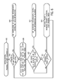
- FIG. 3 is a flow diagram of a process of modifying behavior of a sender device in response to feedback from a receiver device, according to some embodiments
- FIGS. 4A and 4B are message flow diagrams illustrating examples involving lost packets.
- FIG. 5 is a message flow diagram of a process of a first retransmission solution according to some embodiments.
- FIG. 6 is a flow diagram of a flow diagram of a process of the first retransmission solution according to further embodiments.
- FIG. 7 is a timing diagram illustrating various timing relationships
- FIG. 8 is a flow diagram of a process of a second retransmission solution, according to alternative embodiments.
- FIG. 9 is a flow diagram of a congestion window size setting process, according to some embodiments.
- FIGS. 10 and 13 are state diagrams of operations of a receiver device, according to some embodiments.
- FIGS. 11 and 12 are flow diagrams of processes of the receiver device, according to some embodiments.
- FIG. 14 is a state diagram of operation of a sender device according to some embodiments.
- FIGS. 15-16 are flow diagrams of processes of the sender device according to some embodiments.
- FIG. 17 is a block diagram of a network device according to some embodiments.
- MPTCP Multipath Transmission Control Protocol
- IETF Internet Engineering Task Force
- a “connection” between network devices refers to a session that is established using a predefined procedure, such as a procedure defined by MPTCP, TCP (Transfer Control Protocol), or other protocol.
- a connection between network devices can be established over a network that may have one or multiple intermediate devices, such as middleboxes, routers, switches, firewalls, network address translators, proxies, and so forth.
- a subflow refers to a stream of packets belong to a connection (e.g., TCP connection) sent over a path.
- a path refers to a set of links between network devices—a path can be defined by a pair of addresses, such as a source address and a destination address. Multiple subflows of a connection can be provided over multiple paths.
- FIG. 1 illustrates an example arrangement that includes a network 102 connected to a first network device 104 and a second network device 106 .
- network devices include personal digital assistants, mobile telephones, tablet computers, notebook computers, desktop computers, server computers, storage controllers, electronic appliances, or other types of electronic devices.
- the example shown in FIG. 1 shows that multiple subflows 108 and 110 can be provided in a connection established between the network devices 104 and 106 .
- the connection between network devices can have more than two subflows.
- the pair of network devices 104 and 106 can establish multiple connections, where each connection can be associated with its respective set of subflows.
- the first subflow 108 can be part of a path over a mobile communications network, such as a cellular network.
- the second subflow 110 can be over a wireless local area network.
- the subflow 108 or 110 can be part of a wired path.
- each of the network devices 104 and 106 includes a respective MPTCP protocol stack 112 and 114 .
- the protocol stack 112 or 114 includes an application layer (including application software) and an MPTCP layer (for implementing MPTCP functionality).
- TCP/IP Transmission Control Protocol/Internet Protocol
- TCP/IP Transmission Control Protocol/Internet Protocol
- Each TCP/IP instance 116 A or 116 B includes a respective TCP layer 118 A or 118 B and an IP layer 121 A or 121 B.
- the MPTCP layer defines communication over a connection at a connection level (or data level), while each TCP layer defines communication at a subflow level.
- Versions of IP are described by Request for Comments (RFC) 791, entitled “Internet Protocol,” September 1981 (describing Internet Protocol Version 4 (IPv4)), or by RFC 2460, entitled “Internet Protocol, Version 6 (IPv6)) Specification,” dated December 1998.
- RFC 793 entitled “Transmission Control Protocol,” dated September 1981.
- protocol stack 112 or 114 is depicted with an MPTCP layer and TCP/IP instances, it is noted that protocol stacks according to other implementations can include other types of protocol layers. Also, not all layers of the protocol stack 112 or 114 are depicted; there may be other layers that are not depicted.
- the network 102 may include one or multiple blocking intermediate devices 120 A and 120 B, also referred to as sequence hole blocking middle boxes.
- blocking intermediate devices include firewalls, network address translators, proxies (such as performance enhancing proxies), or any other intermediate device that is on the routing path of packets between a sender device and a receiver device and that prevents forwarding of packets to a destination, as an example when the intermediate device detects loss of continuity in sequence numbers in packets received by the intermediate device 120 A or 120 B.
- the blocking intermediate device detects sequence holes in packets received by the intermediate device, then the blocking intermediate device will block the forwarding of packets having sequence numbers after or larger than the missing sequence number to the destination.
- the blocking intermediate device can block the forwarding of packets if the blocking intermediate device detects some other characteristic in a stream of packets from the sender device.
- a blocking intermediate device is on the path of a subflow when the blocking intermediate device is on the routing path of packets between a sender device and a receiver device.
- intermediate devices 120 A and 120 B provided in respective subflows 108 and 110 .
- a blocking intermediate device is provided in just one of the subflows 108 and 110 .
- one or both of the intermediate devices 120 A and 120 B can be non-blocking intermediate devices (a non-blocking intermediate device allows packets to be forwarded to the destination even if there is a sequence hole in the packets). Assuming that the intermediate device 120 A or 120 B is a blocking intermediate device, such blocking intermediate device will block forwarding of packets along the respective subflow ( 108 or 110 ) if the blocking intermediate device detects a sequence hole along that subflow.
- FIG. 2 illustrates an example message flow diagram that illustrates the issue of packet loss occurring that causes a blocking intermediate device 120 (either 120 A or 120 B in FIG. 1 ) to block forwarding of packets.
- packet can refer to a byte, a collection of bytes, or any other grouping of data.
- sequence numbers are associated with bytes. With other protocols, sequence numbers can be associated with other groupings of data.
- packet k (with sequence number s(k)) sent by a sender device (e.g., network device 104 ) is lost ( 202 ) before reaching the blocking intermediate device 120 .
- a lost packet includes a packet that is sent by a sender device to a receiver device and is not received by the receiver device.
- FIG. 2 also shows subsequent transmission of packets k+1, k+2, k+3, and k+4 from the sender device 104 to the blocking intermediate device 120 , having sequence numbers greater than s(k).
- the packets having respective sequence numbers s(k+1) to s(k+4) are blocked ( 204 ) by the blocking intermediate device 120 , due to the sequence hole resulting from loss of the packet k.
- packet k is retransmitted ( 206 ), where the retransmitted packet k is received by the intermediate device 120 and forwarded (represented by arrow 208 ) to the receiver device (e.g., network device 106 ).
- the blocking intermediate device 120 can release ( 210 ) packets k+1, k+2, k+3, and k+4 to receiver device 106 .
- the blocking intermediate device 120 will not block the packets having sequence numbers s(k+1) to s(k+4), since the blocking intermediate device 120 has already seen the packet having sequence number s(k).
- Rule 1 specifies that a missing packet in a particular subflow should be retransmitted on the same subflow.
- Rule 1 if a packet having a particular sequence number was lost in subflow 108 , then the packet having the particular sequence number should be retransmitted on subflow 108 .
- Rule 1 can be considered a retransmission rule at the subflow level.
- Rule 2 specifies that a sender device has to keep data in the sender device's send buffer at the MPTCP connection level as long as the data has not been acknowledged at the connection level as well as on all subflows that the data has been sent on. Maintaining the data in the send buffer allows a sender device to retransmit the data if needed, on the same subflow or on a different subflow. Rule 2 can be considered a retransmission rule at the connection level.
- Rules 1 and 2 are provided due to the possibility that a blocking intermediate device may be present on a subflow of a connection between network devices.
- a sender device that is communicating with a receiver device over a connection
- a first retransmission solution (Retransmission Solution 1) is provided.
- this retransmission solution uses a probing mechanism for determining whether a blocking intermediate device is present.
- the sender device uses feedback from the receiver device to either (1) affirmatively determine that a blocking intermediate device does not exist in the path of a subflow, or (2) determine that the sender device is without knowledge of whether a blocking intermediate device is in the path of a subflow or cannot determine that a blocking intermediate device is in the path of a subflow. If the sender device detects condition (1) (that the sender device has affirmatively determined that a blocking intermediate device does not exist in the path of a subflow), then the sender device modifies its behavior with respect to communication over subflows of a connection between the sender device and the receiver device, by implementing a first behavior with respect to data transmission over subflows of the connection. The first behavior allows the sender device to operate without having to comply with Rule 1 or Rule 2, or both Rules 1 and 2.
- the sender device In response to detecting condition (2) above (the sender device is without knowledge of whether a blocking intermediate device is in the path of a subflow), the sender device implements a second behavior, in which the sender device complies with either Rule 1 or Rule 2, or both.
- a second retransmission solution (Retransmission Solution 2) is provided, in which the probing of Retransmission Solution 1 is not used.
- Retransmission Solution 2 since probing is not used, the sender device is unable to affirmatively determine whether a blocking intermediate device exists or not in the path of a subflow, as can be done with Retransmission Solution 1.
- the sender device determines one of two conditions is present: (a) no blocking intermediate devices exists in a subflow, or a specific lost packet or any lost packet was lost after being forwarded from a blocking intermediate device; or (b) a blocking intermediate device exists, or all packets with a sequence number greater than the sequence number of a lost packet have been lost before reaching the blocking intermediate device or have been lost after the blocking intermediate device or have been discarded by the blocking intermediate device.
- the sender device In response to detecting condition (a) above, the sender device implements a first behavior in which the sender device does not have to comply with Rule 1, but complies with Rule 2. On the other hand, in response to detecting condition (b) above, the sender device implements a second behavior in which the sender device has to comply with both Rule 1 and Rule 2.
- Retransmission Solution 1 With either Retransmission Solution 1 or Retransmission Solution 2 noted above, mechanisms or techniques are provided to allow the sender device to determine that the feedback actually came from the receiver device, and was not generated or altered by some intermediate device. Such mechanisms or techniques are discussed in a section entitled “Receiver Feedback Mechanisms or Techniques” provided further below.
- FIG. 3 illustrates a process according to some embodiments.
- the sender device sends (at 302 ) packets over a network, where the packets are destined to a receiver device.
- the sender device receives (at 304 ) response information that is responsive to the packets sent by the sender device.
- the response information is considered the feedback from the receiver device mentioned above.
- the behavior of the sender device with respect to communication over multiple subflows of a connection is controlled (at 306 ) based on the response information. Controlling the behavior includes causing the sender device to implement different behaviors (first and second behaviors noted above) with respect to data transmission over subflows of a connection between the sender device and the receiver device, in response to the response information indicating respective different conditions.
- the sender device implements the first behavior with respect to data transmission over the subflows of a connection in response to the response information indicating condition (1) or (a) noted above, and the sender device implements the second, different behavior with respect to data transmission over the subflows of a connection in response to the response information indicating condition (2) or (b) noted above.
- FIG. 4A illustrates an example packet retransmission scenario that is in accordance with Rule 1.
- each packet over a respective subflow includes two sequence numbers: a subflow-level sequence number (SSN) and a data-level (or connection-level) sequence number (DSN).
- SSN subflow-level sequence number
- DSN data-level (or connection-level) sequence number
- a subflow-level characteristic such as a sequence number is a characteristic that describes the properties of an individual subflow, i.e. a flow of data packets belonging to a path.
- a data-level or connection-level characteristic such as a sequence number is a characteristic of an MPTCP connection.
- the SSN is employed by the TCP layer 118 A or 118 B in the protocol stack 112 or 114 of FIG. 1 .
- the DSN is used by the MPTCP layer in the protocol stack 112 or 114 .
- Sequence numbers are used by each protocol stack to allow for reliable, ordered delivery of packets.
- FIG. 4A various packets are sent from the sender device to the receiver device along subflows 1 and 2 in transmissions 400 .
- a packet 402 having SSN 201 and DSN 4 was lost in subflow 2 .
- the receiver device sends an acknowledgement (ACK) message 403 to the sender device on subflow 1 , where the ACK message is a cumulative acknowledgement indicating successful receipt of the packets along subflow 1 , including packet 404 containing SSN 102 (as well as packets with SSNs 100 and 101 ).
- ACK acknowledgement
- a cumulative acknowledgement is provided by the receiver device to acknowledge that the receiver device correctly received a packet in a stream (which in the example is packet 404 in subflow 1 ) that implicitly informs the sender device that the previous packets (packets with a lower sequence number) were also received correctly.
- ACK indicates a cumulative acknowledgement.
- Other types of acknowledgements will be indicated with different abbreviations in the discussion below.
- An acknowledgement message 406 provided in subflow 2 acknowledges successful receipt of a packet 408 on subflow 2 , which has SSN 200 and DSN 3 .
- subflow 2 in the example of FIG. 4A is the subflow used for acknowledging the data level sequence number of packets received by the receiver device.
- the acknowledgement message 406 includes a subflow-level ACK: 201 to acknowledge successful receipt of a packet ( 408 ) without any SSN holes containing SSN 200 along subflow 2 , and data-level ACK: 4 to acknowledge successful receipt of packets containing DSNs up to 3 (without any DSN holes) along both subflows 1 and 2 .
- the acknowledgement message 406 sent from the receiver device to the sender device does not acknowledge the SSN of 202 and DSN of 6 in packet 409 , since an SSN hole and DSN hole are present due to loss of the packet 402 .
- the lost packet 402 (originally sent on subflow 2 ) has to be retransmitted on subflow 2 (the lost packet 402 may or may not be retransmitted on subflow 1 in parallel, which depends on the implementation of sender device's retransmission algorithms).
- the lost packet 402 is not retransmitted over subflow 1 .
- the retransmitted packet is designated packet 412 in subflow 2 .
- FIG. 4A also depicts further transmissions 414 of various packets on subflows 1 and 2 , including the retransmitted packet 412 in subflow 2 .
- Acknowledgement messages ( 416 ) are sent by the receiver device to the sender device in response to the packet transmissions 414 . It is assumed that all packets sent in transmissions 414 were successfully received by the receiver device.
- the retransmission of the packet 412 over the same subflow of the lost packet 402 is performed to deal with the possibility of the presence of a blocking intermediate device on subflow 2 , which does not tolerate sequence holes. If another subflow, such as subflow 1 , is a better choice for sending the retransmitted packet 412 (such as due to subflow 1 having lower congestion), then Rule 1 would cause reduced data throughput performance since the retransmitted packet has to be sent over the same subflow, which may be experiencing higher congestion or have other issues.
- subflow 2 may actually be broken, in which case the sender device has to keep resending the lost packet over the same subflow until the sender device determines that subflow 2 is broken, which may take some time and also wastes network resources such as network bandwidth.
- subflow 2 may be a wireless link, and retransmission of the packet 412 over this wireless link may be expensive in terms of usage of radio bandwidth and radio resources.
- retransmission of a TCP packet may trigger even more redundant radio level retransmissions, such as radio level retransmissions due to poor radio link quality.
- FIG. 4B is a message flow diagram illustrating application of Rule 2 discussed above.
- transmissions 400 and 414 are similar to respective transmissions 400 and 414 in FIG. 4A .
- packet 402 originally sent in subflow 2 was lost, which triggered retransmission of the packet, in the form of retransmitted packet 412 in subflow 2 as well as packet 411 in subflow 1 .
- packet 411 in subflow 1 it is assumed that retransmitted packet 412 in subflow 2 was also lost, but the retransmitted packet 411 was received successfully by the receiver device.
- the receiver device In response to packet transmissions 414 over subflows 1 and 2 , the receiver device sends respective acknowledgement messages ( 420 ) to the sender device. Packets with DSN up to 8 were sent by the sender device and received by the receiver device over one or both of the subflows. As a result, the receiver device sends a data-level cumulative acknowledgement sequence number of 9 , as indicated in the acknowledgement message 418 . However, note that due to failure to receive the retransmitted packet 412 , the SSN of the subflow-level acknowledgment in the acknowledgement message 418 is 201 , to indicate that the last successfully received packet in subflow 2 without an SSN hole has an SSN of 200 (namely packet 408 in the FIG. 4B example).
- the sender device In the case where the receiver device is able to send a selective acknowledgement (SACK) instead of a cumulative ACK (where the selected acknowledgement is able to identify respective DSNs after a sequence hole received by the receiver device), the sender device only has to maintain packet(s) with DSN 4 in the send buffer, and does not have to maintain the packets having DSNs 6 and 7 . Even in this latter case, the send buffer of the sender device still has to keep packet(s) having DSN 4 , which consumes storage capacity.
- SACK selective acknowledgement
- a probing-based solution allows the sender device to perform subflow probing to affirmatively determine that a blocking intermediate device does not exists on a subflow between the sender device and the receiver device.
- Retransmission Solution 2 does not use the probing technique, but the sender device is still able to modify its behavior based on feedback received from the receiver device in response to messaging from the sender device.
- FIG. 5 illustrates a probing-based solution (Retransmission Solution 1) according to some embodiments.
- the sender device For determining whether there is a blocking intermediate device between the sender device and the receiver device, the sender device creates a sequence number hole in a subflow by holding one or multiple packets (by not transmitting such held one or multiple packets in the sequence of packets to be transmitted in the subflow). Such held packet(s) is (are) also referred to as “probing packet(s).” Based on feedback from the receiver device in response to the sent packets with a sequence number hole, the sender device can determine whether a blocking intermediate device exists on the subflow.
- the sender device holds packet 502 in subflow 2 , thereby creating a sequence number hole in subflow 2 . More generally, the sender device holds one or more packets (e.g., packet 502 in FIG. 5 ) from a subflow belonging to a connection but sends packet(s) with higher DSN(s) (e.g., 512 and 514 ) to create a sequence number hole in the subflow. The held packet is not sent on any subflow, but rather is stored in a memory, buffer, or other storage of the sender device.
- packets e.g., packet 502 in FIG. 5
- DSN(s) e.g., 512 and 514
- the receiver device sends a data-level acknowledgement to indicate what packets belonging to the connection (on multiple subflows) have been received.
- the receiver device also sends a subflow-level acknowledgement on the subflow being probed (subflow 2 in FIG. 2 ) to indicate what packets have been received over the subflow being probed. More specifically, a subflow-level ACK message 504 in subflow 1 provides a cumulative acknowledgement of packets received in subflow 1 , with the ACK message 504 containing acknowledge SSN 103 to indicate successful receipt of packet 506 containing SSN 102 .
- An acknowledgement message 508 in subflow 2 uses selective acknowledgement (SACK) at the subflow level.
- SACK selective acknowledgement
- the subflow-level SACK in message 508 allows the receiver device to indicate successful receipt of a packet 510 before the sequence number hole, and packets 512 and 514 after the sequence number hole in subflow 2 .
- the cumulative acknowledgment (ACK) at the connection level in the acknowledgement message 508 provides cumulative acknowledgement of successful receipt of packets containing DSNs up to 3 in both subflows 1 and 2 .
- the sender device can determine from the acknowledgement message 508 that the receiver device successfully received packets having SSNs having values greater than the value of the SSN ( 201 ) of the packet 502 that was held by the sender device. From this, the sender device can determine (at 516 ) that there is no blocking intermediate device between the sender device and the receiver device in subflow 2 . On the other hand, if the SACK in the acknowledgement message 508 would have contained just the SSN 200 (and not 202 and 203 ), the sender device would not be able to determine that there is no blocking intermediate device in subflow 2 . In such a scenario, the sender device is without knowledge of whether the blocking intermediate device is in subflow 2 .
- the receiver device if the receiver device did not receive packet n, but receives a packet n+1, the receiver device sends a duplicated ACK for sequence number n. If the receiver device later receives another packet n+2, then the receiver device will send another duplicate ACK for sequence number n.
- the duplicate ACKs informs the sender device that a sequence hole has been detected at the receiver device.
- a similar procedure according to FIG. 5 can be performed for probing subflow 1 to determine whether a blocking intermediate device exists in subflow 1 .
- the sender device can release all packets in its send buffer at the connection level as soon as the sender device receives an acknowledgement at the connection level that the packets have been received.
- retransmission efficiency can be improved (e.g., to provide improved network throughput), and send buffer usage efficiency at the sender device can also be improved.
- a probing timer is used for each subflow of a connection.
- the sender device starts the probing timer for a given subflow when the sender device starts the probing and creates a sequence number hole by holding one or more packets.
- the probing timer starts at a non-zero timeout value, and decrements over time until the probing timer reaches a threshold value (such as zero), at which point the probing timer is considered to have expired.
- the probing timer can start at an initial value (such as zero) and increments over time, with the probing timer expiring when the probing timer reaches some upper threshold timeout value.
- the sender device holds (at 608 ) at least one packet having sequence number n, but sends a packet having sequence number n+1 on the subflow to be probed. The held packet having sequence number n is not sent on any other subflow. Also, the sender device starts the probing timer.
- the sender device determines (at 610 ) whether an acknowledgement has been received from the receiver device that selectively acknowledges receipt of packet(s) with sequence number(s) greater than n. If so, then the sender device determines (at 612 ) that there is no blocking intermediate device on the path of the subflow being probed, and therefore, retransmission optimization is allowed (the sender device does not have to comply with Rule 1 or 2 or both for the subflow being probed).
- the sender device releases (at 616 ) the held packet(s) and stops the probing timer. However, if the sender device receives the DACK or SACK as described above before the probing timer expires, then the sender device proceeds to task 612 . If the probing timer expires, the sender device determines that it does not know whether there is a blocking intermediate device and the sender device reattempts the probing at some later time.
- acknowledgement messages such as a DACK or a SACK
- the sender device After the probing is done and it is determined that there is no blocking intermediate device in the path of a particular subflow, if some packets are lost in the particular subflow (e.g., subflow 1 ), but these lost packets were retransmitted over an alternate subflow (e.g. subflow 2 ) successfully (i.e. Rule 1 not complied with), the sender device does not retransmit the lost packets over subflow 1 .
- the sender device uses instead an option (referred to as a “re-sync” option) to instruct the receiver device to skip the packets with certain SSNs by providing the SSNs of the packets to be skipped or the largest SSN of the packet to be skipped, namely the lost packets successfully retransmitted by the sender device and successfully received by the receiver device over the alternate subflow.
- a “re-sync” option Upon receiving the “re-sync” option, or upon determining that the sender device uses the “re-sync” option, the receiver device moves the SSN forward to the value indicated by the sender device or to the largest value of the SSNs indicated by the sender device, and does not request retransmission of the missing packets.
- the receiver device can send this signaling or indication to the sender device in a variety of ways. For example, the receiver device sends a new TCP option (in a TCP message) to the sender device to notify the sender device of the subflow change and to provide a reason for the change, e.g., the receiver device moved from one access network to another access network.
- the sender device determines that the subflow changed (e.g., the IP address of the sender device changed or the sender device received an indication from the receiver device of a path change)
- the sender device performs path probing according to FIGS. 5 and 6 .
- the probing timer timeout value should be set at least larger than one round trip time (RTT) (time for data to go from the sender device to the receiver device plus the time for a responsive acknowledgement to go from the receiver device to the sender device) to allow enough time for the sender device to receive the feedback from the receiver device.
- RTT round trip time
- the probing timer starts at T probing , and decrements to zero, at which point the probing timer expires.
- constraint (2) specifies that the probing timer timeout value should not be too large for various reasons. First, the delay in performing the probing should be within acceptable limits, such as per requirements of an application in the sender device. Constraint (2) is expressed as: T probing ⁇ D app , (2)
- a further constraint, constraint (3) specifies that the probing timer timeout value should be set to avoid an increased likelihood of TCP timeout (which occurs when a sender device fails to receive an acknowledgement of a sent packet within a predefined timeout duration).
- TCP timeout which occurs when a sender device fails to receive an acknowledgement of a sent packet within a predefined timeout duration.
- the probing timer value should be set according to the following further constraint (3):
- FIG. 7 is a timing diagram to illustrate the timing relationships noted above.
- Time T 0 is the time at which a timeout timer for an unacknowledged packet (n ⁇ k) is started.
- the overall timeout duration (T timeout ) is represented by 702 . If an acknowledgement of packet n ⁇ k is not received by time T 5 (which is the timeout duration after T 0 ), then timeout will occur at the sender device for packet (n ⁇ k).
- the probing timer is started at Time T 1 , when packet (n+1) is sent. Note that the probing packet (held packet) is packet n.
- the probing timer value (T probing ) is represented by duration 704 .
- the value T remain ( 706 ) is the remaining time of the timeout timer for unacknowledged packet (n ⁇ k), as measured from the start of the probing timer (T 1 ).
- time T 2 represents a time when an acknowledgement of packet (n+1) is supposed to be received. If the acknowledgement for packet (n+1) is not received by time T 3 , which is T probing after T 1 , then the sender device will release the held packet (packet n).
- Time T 4 represents the time when the acknowledgement for packet n is supposed to be received.
- the value of T probing should be less than the minimum of (T remain ⁇ RTT upbound ) for all unacknowledged packets.
- T probing value cannot be found to satisfy constraints (1), (2) and (3) above.
- alternative embodiments involve the sender device splitting a probing packet into two (or more) packets of smaller sizes. The sender holds one of the split packets, and transmits the other(s).
- the number of packets transmitted is at least the same as (or greater than) in the normal case, and therefore there is no decrease in robustness with respect to timeout.
- the probing timer value only has to satisfy constraints (1) and (2).
- Retransmission Solution 2 An alternative solution (Retransmission Solution 2) does not employ probing.
- the sender device and the receiver device behave as legacy TCP devices until loss of a packet, such as packet n, occurs. Packet loss is detected as in regular TCP, such as through subflow-level feedback from the receiver device or timeout.
- the mechanisms described in the section below titled “Feedback Mechanisms or Techniques” are used so the sender can determine with high confidence that the feedback came from the receiver and was not a feedback generated or altered by an intermediate device.
- the sender device detects that one or more packets are lost when the sender receives multiple duplicate subflow-level ACKs with the same ACK number.
- the receiver device sends duplicate acknowledgements when the receiver device receives one or more packets with higher SSNs than the SSN of the lost packet.
- the sender device determines that one or more packets are lost when the TCP timeout timer expires.
- the sender device when the sender device determines that one or more packets are lost (triggering event 802 ), the sender device reduces (at 804 ) a congestion window size based on TCP mechanisms.
- TCP TCP
- a sender device can maintain a congestion window for specifying how many bytes of data the sender device is allowed to send before the sender device has to receive an acknowledgement from the receiver device.
- various TCP mechanisms are available to reduce the size of the congestion window.
- Detection that a packet is lost can be based on receiving k duplicate ACK messages (for packet having SSN n) or the sender device timing out after the predefined timeout duration from when the packet having SSN n was sent.
- the sender device determines (at 806 ) that a packet with SSN n is lost, if the sender device has not received an indication (in the form of an acknowledgement, such as a subflow-level SACK) that any packet with SSN greater than n has been delivered to the receiver device, then the sender device determines that either a blocking intermediate device is present or all packets with sequence numbers greater than n have been lost or are extremely delayed (and thus has resulted in a timeout). In this case, the sender device retransmits (at 808 ) the lost packet (having SSN n) on the original subflow (complies with Rule 1). In task 808 , the sender device can also comply with Rule 2.
- the sender device detects that a packet with SSN n is lost, if the sender device receives (as determined at 806 ) an indication that the receiver device has received one or more packets with SSN greater than n, then that indicates either that no blocking intermediate device is present, or packets were lost after transmission by an intermediate device.
- the sender device has the option to skip (at 810 ) retransmitting the packet with SSN n on the original path, if the packet has already been retransmitted over an alternate subflow, or to retransmit the packet on the most suitable subflow (e.g., least congested subflow). In other words, the sender device does not have to comply with Rule 1.
- a sender device maintains a congestion window for specifying how many bytes of data the sender device is allowed to send before the sender device has to receive an acknowledgement from the receiver device.
- a “congestion window” can refer to any time duration or indication of amount of data following transmission of a particular packet, in which the sender device is allowed to continue to send further data in the congestion window.
- the sender device Upon expiration of the congestion window (either the time duration of the congestion window has passed or the amount of data indicated by the congestion window has been exceeded), the sender device will no longer be able to transmit further data, until the congestion window is updated.
- mechanisms or techniques are provided for setting the size of a congestion window that potentially can utilize information received over multiple subflows. For example, a data-level acknowledgement (DACK) or selective ACK (SACK) can be received on a subflow different from a given subflow where a subflow-level ACK was lost.
- DACK data-level acknowledgement
- SACK selective ACK
- the sender device will be able to control the congestion window size in a more efficient manner than if the sender device had to trigger adjustment of the congestion window size based on acknowledgment information carried in just the given subflow.
- Congestion window size setting mechanisms exist that allow a sender device to reduce a congestion window size upon receipt of k duplicate acknowledgements carrying sequence number n (which indicates loss of the packet having sequence number n). For example, some TCP mechanisms divide the congestion window size by two (in other words, the congestion window size is reduced by half) in response to detecting k duplicate acknowledgements.
- TCP mechanism is the NewReno mechanism, as described in RFC 3782, entitled “The NewReno Modification to TCP's Fast Recovery Algorithm,” dated April 2004.
- Another TCP mechanism for reducing window size is the TCP Reno mechanism.
- Other mechanisms can also be employed in other examples.
- the congestion window size is usually reduced to a relatively small value, such as 1. Reducing the congestion window size to such a relatively small value can adversely affect performance of the sender device.
- TCP mechanisms reduce the congestion window size by half in response to receiving k (where k is a preconfigured number) duplicate acknowledgements of a packet having sequence number n.
- the sender device In an environment in which a connection can have multiple subflows, if any of the subflows were to experience congestion or to break, then subflow-level acknowledgements sent by the receiver device on the particular subflow may not be received by the sender device. Thus, if the sender device is unable to receive duplicate acknowledgements regarding a packet that may potentially be lost, then the sender device will not be able to implement a fast recovery mechanism in which the congestion window size is divided in half (or reduced by some other smaller amount) as compared to reducing the congestion window size to one (when a timeout occurs). Effectively, the inability of the sender device to receive subflow-level duplicate acknowledgements means that the sender device would not be able to trigger the fast recovery congestion window size setting technique that is responsive to receiving k duplicate acknowledgements.
- the sender device uses the acknowledgement information received over a different subflow than the subflow over which subflow-level acknowledgements may have been lost.
- the receiver device may have sent subflow-level duplicate acknowledgements to the sender device along subflow 1 .
- subflow 1 may be experiencing congestion, in which case the subflow-level duplicate acknowledgements may not reach the sender device, which may mean that the sender device will not be able to detect k duplicate acknowledgements along subflow 1 .
- the sender device uses data-level acknowledgement information sent along subflow 2 (different from subflow 1 ) to determine whether the receiver device has received k packets having sequence numbers following a particular packet sent by the sender device to the receiver device along subflow 1 .
- the data-level acknowledgement information in the different subflow (subflow 2 ) contains sufficient information to allow the sender device to make such determination.
- mapping information may be maintained at the sender device to map connection-level sequence numbers to subflow-level sequence numbers.
- a connection-level acknowledgement information (in a DACK) is mapped by the sender device to subflow-level sequence numbers that the sender device uses to determine from the connection-level acknowledgement information whether the receiver device has received k packets following a particular packet.
- the sender device determines whether the receiver device has received k packets following a particular packet by mapping a connection-level acknowledgement information (in a DACK) to subflow-level sequence numbers.
- the sender device determines based on the acknowledgement information on this different subflow that k packets following a particular packet have been received by the receiver device on subflow 1 , then the sender device triggers the fast recovery congestion window size setting mechanism, such as by reducing the congestion window size by half or by reducing the congestion window by any other factor that may, for example, be preconfigured in the device or that the device determines dynamically.
- the sender device reduces the congestion window size by an amount smaller than typically performed for TCP timeout, such as by using the Reno or NewReno techniques (or some other technique).
- a second congestion window setting technique involves determining a ratio of two parameters, N and M.
- the parameter N is a number of packets with SSN greater than n received by the receiver device, as indicated from a data-level acknowledgement (ACK or SACK).
- the parameter M is the total number of packets with SSN greater than n the sender device has sent. If the ratio N/M is greater than a predefined threshold T when a retransmission timeout timer of packet n (the lost packet) expires, the sender device reduces the congestion window size as if duplicate subflow-level ACKs were received (e.g., reducing the congestion window by half) rather than reducing the congestion window size to a low value such as 1.
- the sender device initializes the congestion window size as conventionally performed by TCP when the timer expires (e.g., the congestion window size is et to 1).
- N/M some other comparison of N and M is performed, such as by taking a difference between N and M.
- FIG. 9 is a flow diagram of a congestion size setting technique according to some embodiments. The process of FIG. 9 can use either the first or second congestion window size setting technique discussed above.
- the sender device receives (at 902 ) data-level acknowledgement information in a subflow different from a subflow over which duplicate subflow-level acknowledgements may have been lost. Based on the data-level acknowledgement information, the sender device determines (at 904 ) a number of packets received with SSNs greater than n, where n is the SSN of the packet that has not yet been acknowledged.
- the sender device Based on such determined number of packets with SSN greater than n received by the receiver device, the sender device reduces (at 906 ) the congestion window size.
- the reduction of the congestion window size can be according to either first or second congestion window size setting technique discussed above, according to some implementations.
- the sender device reduces the congestion window size by an amount less than a reduction that would occur for a TCP timeout.
- retransmission solutions 1 and 2 discussed above depend on the sender device being able to determine with high confidence that the receiver device received packets with SSN greater than n, where n is the SSN of the lost or held packet.
- Some intermediate devices can modify or overwrite a subflow-level acknowledgement sent by the receiver device to the sender device, or generate (originate) a subflow-level ACK autonomously (even if the receiver device never sent one). For reliable operations, the sender device should know whether a subflow-level acknowledgement was sent by the receiver device or not.
- subflow-level feedback messaging refers to messaging sent by a receiver device over a subflow in response to messaging received by the receiver device from a sender device.
- the sender device determines that a subflow-level ACK was sent by the receiver device by verifying that the subflow-level ACK is received together with an MPTCP-specific option.
- An “MPTCP-specific option” refers to a field or value that is used by MPTCP, but not by regular TCP.
- the MPTCP-specific option can be a data-level acknowledgement (ACK or SACK), which is used by MPTCP, but not by regular TCP.
- the MPTCP-specific option contains MPTCP-specific signaling (in the form of a field or value) for implementing MPTCP functionality.
- the sender device relies on the presence of an MPTCP-specific option (such as data-level acknowledgement) to determine that the subflow-level ACK (or subflow-level SACK) came from the receiver device (in other words, the subflow-level acknowledgement was not altered or overwritten by or originated from an intermediate device).
- an MPTCP-specific option such as data-level acknowledgement
- This approach works only if a “transparent middlebox” assumption is true.
- a transparent middlebox is an intermediate device that does not allow an MPTCP-specific option (generated by the receiver device) through if the intermediate device altered the subflow-level ACK (or subflow-level SACK), or if the intermediate device generated a new subflow-level ACK (or subflow-level SACK) that overrides the one from the receiver device.
- a second approach applies in cases where it is not desirable or possible for the receiver device to send MPTCP-specific signaling in an MPTCP-specific option. For example, a message from the receiver device may not have enough space in the options section of the message for the MPTCP-specific option. Alternatively, there may not be any MPTCP-specific signaling to send by the receiver device. For such cases, a new MPTCP-specific Receiver Originated Flag option is produced, where this MPTCP-specific Receiver Originated Flag option is composed of a relatively small amount of information, such as 3 bytes. In some embodiments, the Receiver Originated Flag is encoded as a TCP option with 3 fields: KIND (1 byte), LENGTH (1 byte), and flag (1 byte).
- the Receiver Originated Flag can be considered a No-operation (NOP) MPTCP-specific option—this NOP MPTCP-specific option is different from the MPTCP-specific option of Approach 1 that contains MPTCP-specific signaling to implement MPTCP functionality. Like the Approach 1, Approach 2 works only if the transparent middlebox assumption is true.
- a third approach (Approach 3), unlike Approaches 1 and 2, does not make any assumption about the middlebox behavior.
- receiver device generates a subflow-level ACK (or subflow-level SACK) and calculates a receiver checksum of the subflow-level ACK (or subflow-level SACK) and sends the receiver checksum to the sender device.
- a checksum refers to a value that is calculated by applying a predefined function (such as a hash function) on content of a message to be communicated.
- the checksum is calculated based on the content of the subflow-level acknowledgement (ACK or SACK) sent by the receiver device.
- the sender device Upon receiving a subflow-level ACK (or subflow-level SACK) (along with the receiver checksum), the sender device calculates a checksum of the subflow-level ACK (or subflow-level SACK) and compares the sender-calculated checksum with the receiver checksum. The sender device determines that the subflow-level ACK (or subflow-level SACK) originated from the receiver device if the checksums match. This approach works for both transparent and non-transparent middleboxes.
- the receiver checksum is sent as a standalone option and the receiver checksum is encoded as: KIND (1 byte), LENGTH (1 byte), and checksum (cksum bytes).
- the parameter cksum can be as small as 1, which means that the checksum field is one byte long. In such examples, the receiver checksum is made up of 3 bytes. In other examples, the parameter cksum can be greater than one, in which case the receiver checksum will be longer than 3 bytes. This approach of using a standalone receiver checksum option is referred to as “Approach-3-Basic.”
- the receiver checksum is sent along with other options in a message (e.g., if the receiver device has to send other options) by appending the checksum bytes (without the associated KIND and LENGTH fields described above) to the other options being sent.
- Each of the MPTCP-specific option of Approach 1, MPTCP-specific Receiver Originated Flag option of Approach 2, and checksum of Approach 3 can be considered generally as “predefined information” useable by a sender device to confirm whether the source of feedback messaging is the receiver device.
- predefined information is unable to be changed or generated by an intermediate device in a path between the sender device and the receiver device over which the feedback messaging is communicated, even though the intermediate device may be capable of modifying another portion of the feedback messaging carrying the predefined information, or originating feedback messaging.
- the MPTCP-specific information according to Approach 1 or 2 or the checksum according to Approach 3 is not changeable by an intermediate device.
- a receiver device can transition between a “sequence hole” state 1002 , and a “no sequence hole” state 1004 . Assuming the receiver device is in the “no sequence hole” state 1004 , the receiver device transitions to the “sequence hole” state 1002 upon detecting an event indicating that the receiver device has detected a sequence hole (e.g., the receiver device detects a sequence number hole in the SSN numbering) in messaging received from the sender device. The receiver device remains in the “sequence hole” state 1002 for as long as the sequence hole condition is present.
- the event indicating that the receiver device has detected a sequence hole is one example of a trigger event. More generally, a trigger event that cause the receiver device to transition to the “sequence hole” state 1002 includes an event indicating a need for the sender device to receive subflow-level feedback information from the receiver device.
- the receiver device Upon receiving an event indicating that the packets previously missing (that caused the sequence number hole) have been received, such as along the same subflow, the receiver device transitions to the “no sequence hole” state 1004 , where the receiver device remains until the receiver device detects another sequence hole.
- the receiver device uses one of the three approaches (Approaches 1-3) above for providing feedback to the sender device so long as the receiver device is in the “sequence hole” state 1002 .
- Approaches 1-3 Approaches 1-3
- the receiver device does not use any of the Approaches 1-3 for feedback (in other words, the receiver device does not include the predefined information of any of Approaches 1-3 in feedback messaging), unless it has other reasons to send an MPTCP-specific option (e.g., a data-level acknowledgement).
- the receiver device can also have various modes of operation, including mode A and mode B, in some examples.
- the receiver devices behaves according to mode A when the receiver device cannot determine if the transparent middlebox assumption is true.
- mode A the receiver device uses Approach 3 (either Approach-3-Basic or Approach-3-Opt) discussed above).
- Approach 3 either Approach-3-Basic or Approach-3-Opt
- mode B the receiver device is able to use Approach 1 or Approach 2 discussed above.
- FIG. 11 illustrates the mode A operation of the receiver device.
- the receiver device determines (at 1102 ) if the receiver device has to send MPTCP-specific signaling in an MPTCP-specific option. If so, then the receiver device uses Approach-3-Opt for the checksum feedback (at 1104 ).
- Approach-3-Opt refers to the approach in which a receiver checksum is appended to an MPTCP-specific option.
- the receiver device determines (at 1102 ) that the receiver device does not have to send MPTCP-specific signaling in an MPTCP-specific option, then the receiver device uses Approach-3-Basic for the checksum feedback (at 1106 ), where in this approach the receiver checksum is sent as a standalone option.
- FIG. 12 depicts an operation of the receiver device in mode B.
- the receiver device determines (at 1202 ) whether the receiver device has to send MPTCP-specific signaling in an MPTCP-specific option. If so, then Approach 1 is used (at 1204 ) for providing feedback to the sender device. As discussed above, Approach 1 refers to sending an MPTCP-specific option to alert the sender device that the message is from the receiver device (rather than from an intermediate device).
- the receiver device uses (at 1206 ) Approach 2 for feedback, where Approach 2 refers to use of the Receiver Originator Flag discussed above.
- the above 3 approaches can be combined, such as follows.
- the receiver device can transition between mode A and mode B according to the state diagram in FIG. 13 .
- the receiver device starts initially in mode A (in which the receiver device uses checksum feedback).
- a first event is an event indicating that it is safe to switch to mode B.
- the receiver device determines that the “transparent middlebox” assumption is true and therefore that it is safe to switch to mode B. The determination can be based on: (1) a priori knowledge of the system configuration, or (2) a specific “checksum-match” signaling from the sender device (details on such signaling are provided further below), or (3) some other mechanism.
- a second event is a subflow change event. This is typically due to mobility when a network device changes its IP address or other parameter due to movement of the network device between different access networks.
- the receiver device In response to the second event, the receiver device cannot determine that the “transparent middlebox” assumption is still true on the new subflow and therefore has to transition to mode A.
- the receiver device in response to detecting the first event (safe to switch to mode B), the receiver device sends a “Switch-to-B” notification.
- the receiver device sends the “Switch-to-B” notification to the sender device when the receiver device determines that it is safe to switch to mode B to inform the sender device that the receiver device has switched to mode B.
- the sender device Upon receiving the Switch-to-B notification, the sender device processes the feedback from the receiver device according to mode B.
- the Switch-to-B notification is carried in an explicit signaling (e.g., by using a new option).
- the MPTCP-specific option (Approach 2 above) can be used as the “Switch-to-B” notification.
- the receiver device provides a “Switch-to-B” notification implicitly by stopping to use Approach 3 (checksum feedback), i.e., by not including any more checksums as described in Approach 3.
- the receiver device in response to detecting the second event (subflow change event), the receiver device sends a “Switch-to-A” notification.
- the receiver device sends the “Switch-to-A” notification to the sender device to inform the sender device that the receiver device has switched to mode A.
- the sender device processes the feedback from the receiver device according to mode A.
- the “Switch-to-A notification” is carried in explicit signaling (e.g., by using a new option).
- the receiver device sends the “Switch-to-A notification” implicitly by resuming the use of Approach 3 (i.e., the receiver device resumes sending the checksums of Approach 3).
- the sender device also operates according to mode A or B, and transitions between these modes according to FIG. 14 .
- the sender device starts initially in mode A. Two events can be received by the sender device.
- a first event is reception of a “Switch-to-A” notification, as discussed above, which can be explicit or implicit.
- a second event is reception of a “Switch-to-B” notification, as described above, which can be explicit or implicit.
- the sender device in response to receiving a “Switch-to-A” notification, switches to mode A operation. In response to receiving a “Switch-to-B” notification, the sender device transitions to mode B.
- the sender and receiver devices communicate different types of the “predefined information” (according to Approach 1, 2, or 3) in feedback messaging (from the receiver device to the sender device) depending on which mode (mode A or mode B) the sender and receiver devices are in.
- FIG. 15 shows mode A operation of the sender device.
- the sender device In mode A, the sender device expects to receive feedback from the receiver device according to mode A—in other words, the sender device expects to receive the receiver checksum of Approach 3 discussed above.
- the sender may receive feedback according to mode B—that is, there is no receiver checksum.
- the sender device When entering mode A, the sender device initializes a Mismatch_Counter and Match_Counter to zero, and sets a “Transition-to-B-pending” flag to false.
- the sender device determines (at 1502 ) whether a receiver checksum is present in a received packet. If so, the sender device determines (at 1504 ) if the receiver checksum matches the sender-calculated checksum. If not, the sender device increments (at 1506 ) the Mismatch_Counter. On the other hand, if the receiver checksum matches the sender-calculated checksum, the sender device increments (at 1508 ) the Match_Counter.
- the sender device effectively counts the instances of checksum matches and mismatches, respectively. In some examples, when the count of matches exceeds a value of K1 times the count of mismatches (as determined at 1510 ), the sender device is able to use (at 1514 ) a subflow-level acknowledgment from the receiver device, since the sender device has determined with high confidence (due to MATCH_COUNTER>K1*MISMATCH_COUNTER) that the “transparent middlebox” assumption is true. If the determination at 1510 is not true, then the sender device does not use the subflow-level acknowledgement from the receiver device. The sender device next determines (at 1515 ) if MATCH_COUNTER is greater than K2.
- K1 and K2 are parameters that can be preconfigured, for example. If the determination at 1515 is true, the sender device sends (at 1516 ) a “checksum-match” signaling to the receiver device (to notify the receiver device that the “transparent middlebox” assumption is true), and sets the “Transition-to-B-pending” flag to true. When the “Transition-to-B-pending” flag is true, the sender device is confident that the “transparent middlebox” assumption is true and therefore does not have to use a receiver checksum to validate that feedback is from the receiver device (in other words, Approach 1 or 2 is sufficient).
- the sender device determines (at 1518 ) whether the “Transition-to-B-Pending” flag is true. If so, the sender device determines (at 1520 ) if the receiver packet contains a predefined receiver option (either the MPTCP specific option of Approach 1 or the Receiver Originator Flag of Approach 2). If not, then the process returns (to 1502 ). However, if the determination at 1520 is true, then the sender device uses (at 1522 ) the subflow-level acknowledgment from the receiver device, and the sender device switches (at 1524 ) to mode B.
- a predefined receiver option either the MPTCP specific option of Approach 1 or the Receiver Originator Flag of Approach 2
- switch performed at 1524 is in response to an implicit “Switch-to-B” notification, when the receiver device simply stops sending receiver checksums. If the “Switch-to-B” notification is explicit, the sender device switches to mode B when the sender device sees the corresponding explicit signaling.
- FIG. 16 shows mode B operation of the sender device.
- the sender device determines (at 1602 ) if a receiver checksum is present in a received packet. If so, then that is an implicit “Switch-to-A” notification, in which case the sender device transitions (at 1604 ) to mode A.
- mode A the sender device expects to receive receiver checksums in messages to confirm that the messages originate from the receiver device (rather than from an intermediate device).
- the sender device determines (at 1606 ) whether the received message contains a predefined receiver option (either an MPTCP-specific option or a Receiver Originated Flag). If not, the process returns. However, if the determination at 1606 is true, then the sender device uses (at 1608 ) the subflow-level acknowledgment from the receiver device. If the determination at 1606 is not true, then the sender device does not use the subflow-level acknowledgement from the receiver device.
- a predefined receiver option either an MPTCP-specific option or a Receiver Originated Flag
- FIG. 17 is a block diagram of a network device 1700 , which can be network device 104 or 106 in FIG. 1 , for example.
- the network device 1700 includes machine-readable instructions 1702 executable on one or multiple processors 1704 .
- the processor(s) 1704 is (are) connected to storage media 1706 .
- the network device also includes a network interface 1708 to allow the network device 1700 to communicate over a data network, such as network 102 in FIG. 1 .
- a protocol stack such as protocol stack 112 or 114 depicted in FIG. 1 , can be implemented in the network interface 1708 or as part of the machine-readable instructions 1702 , or both.
- the machine-readable instructions 1702 or the network interface 1708 , or some combination thereof, can perform the various tasks discussed above.
- a processor can include a microprocessor, microcontroller, processor module or subsystem, programmable integrated circuit, programmable gate array, or another control or computing device.
- Data and instructions are stored in respective storage devices, which are implemented as one or more computer-readable or machine-readable storage media (e.g., 1706 ).
- the storage media include different forms of memory including semiconductor memory devices such as dynamic or static random access memories (DRAMs or SRAMs), erasable and programmable read-only memories (EPROMs), electrically erasable and programmable read-only memories (EEPROMs) and flash memories; magnetic disks such as fixed, floppy and removable disks; other magnetic media including tape; optical media such as compact disks (CDs) or digital video disks (DVDs); or other types of storage devices.
- DRAMs or SRAMs dynamic or static random access memories
- EPROMs erasable and programmable read-only memories
- EEPROMs electrically erasable and programmable read-only memories
- flash memories such as fixed, floppy and removable disks
- magnetic media such as fixed, floppy and removable disks
- optical media such as compact disks (CDs) or digital video
- the instructions discussed above can be provided on one computer-readable or machine-readable storage medium, or alternatively, can be provided on multiple computer-readable or machine-readable storage media distributed in a large system having possibly plural nodes.
- Such computer-readable or machine-readable storage medium or media is (are) considered to be part of an article (or article of manufacture).
- An article or article of manufacture can refer to any manufactured single component or multiple components.
- the storage medium or media can be located either in the machine running the machine-readable instructions, or located at a remote site from which machine-readable instructions can be downloaded over a network for execution.
Abstract
Description
T probing>RTTrelease, (1)
-
- where Tprobing is the probing timer value, and
- RTTrelease is the RTT value when the probing packet (the held packet) is released.
T probing <D app, (2)
-
- where
- Dapp is the delay limit per application requirement.
-
- where
- Tremain is the remaining time of the timeout timer for an unacknowledged packet, and
- RTTupbound is the maximum of the past RTT values at the sender device.
Claims (18)
Priority Applications (5)
| Application Number | Priority Date | Filing Date | Title |
|---|---|---|---|
| US13/041,019 US9503223B2 (en) | 2011-03-04 | 2011-03-04 | Controlling network device behavior |
| CA2828600A CA2828600C (en) | 2011-03-04 | 2011-06-01 | Controlling network device behavior |
| PCT/CA2011/000645 WO2012119214A1 (en) | 2011-03-04 | 2011-06-01 | Controlling network device behavior |
| CN201180070612.2A CN103503357B (en) | 2011-03-04 | 2011-06-01 | Method for controlling network device behavior and network device |
| EP11860484.2A EP2681880B1 (en) | 2011-03-04 | 2011-06-01 | Controlling network device behavior |
Applications Claiming Priority (1)
| Application Number | Priority Date | Filing Date | Title |
|---|---|---|---|
| US13/041,019 US9503223B2 (en) | 2011-03-04 | 2011-03-04 | Controlling network device behavior |
Publications (2)
| Publication Number | Publication Date |
|---|---|
| US20120226802A1 US20120226802A1 (en) | 2012-09-06 |
| US9503223B2 true US9503223B2 (en) | 2016-11-22 |
Family
ID=46753999
Family Applications (1)
| Application Number | Title | Priority Date | Filing Date |
|---|---|---|---|
| US13/041,019 Active 2032-07-20 US9503223B2 (en) | 2011-03-04 | 2011-03-04 | Controlling network device behavior |
Country Status (5)
| Country | Link |
|---|---|
| US (1) | US9503223B2 (en) |
| EP (1) | EP2681880B1 (en) |
| CN (1) | CN103503357B (en) |
| CA (1) | CA2828600C (en) |
| WO (1) | WO2012119214A1 (en) |
Cited By (7)
| Publication number | Priority date | Publication date | Assignee | Title |
|---|---|---|---|---|
| US20170187497A1 (en) * | 2015-12-28 | 2017-06-29 | Alcatel-Lucent Usa Inc. | Fast coupled retransmission for multipath communications |
| US20190166041A1 (en) * | 2016-07-08 | 2019-05-30 | Alcatel Lucent | Flow aggregation and routing for multi-connectivity client devices |
| US10362496B2 (en) * | 2014-07-21 | 2019-07-23 | Huawei Technologies Co., Ltd. | Link control node and method, and communications system |
| US10476992B1 (en) * | 2015-07-06 | 2019-11-12 | F5 Networks, Inc. | Methods for providing MPTCP proxy options and devices thereof |
| US10721269B1 (en) | 2009-11-06 | 2020-07-21 | F5 Networks, Inc. | Methods and system for returning requests with javascript for clients before passing a request to a server |
| US11159443B2 (en) * | 2015-12-15 | 2021-10-26 | International Business Machines Corporation | Queue management in a forwarder |
| US11258820B2 (en) | 2015-07-06 | 2022-02-22 | Shape Security, Inc. | Request modification for web security challenge |
Families Citing this family (45)
| Publication number | Priority date | Publication date | Assignee | Title |
|---|---|---|---|---|
| US11140178B1 (en) | 2009-11-23 | 2021-10-05 | F5 Networks, Inc. | Methods and system for client side analysis of responses for server purposes |
| US9294548B2 (en) * | 2010-12-22 | 2016-03-22 | Telefonaktiebolaget L M Ericsson (Publ) | Mobility handling in a communication network |
| US9699274B2 (en) * | 2011-07-25 | 2017-07-04 | Alcatel Lucent | Method and apparatus for reliable session migration |
| US20150237525A1 (en) * | 2012-09-24 | 2015-08-20 | Telefonaktiebolaget L M Ericsson (Publ) | Traffic Shaping and Steering for a Multipath Transmission Control Protocol Connection |
| US9432458B2 (en) * | 2013-01-09 | 2016-08-30 | Dell Products, Lp | System and method for enhancing server media throughput in mismatched networks |
| US9432251B2 (en) * | 2013-03-08 | 2016-08-30 | Qualcomm Incorporated | Enhanced acknowledgement and retransmission mechanism |
| KR102051504B1 (en) * | 2013-05-15 | 2019-12-03 | 삼성전자주식회사 | Method and apparatus for transmitting and receiving data packets in a wireless communication system |
| CN103326831A (en) * | 2013-06-04 | 2013-09-25 | 华为终端有限公司 | Link processing method and mobile terminal in multichannel transmission control protocol |
| EP2882148A1 (en) * | 2013-12-09 | 2015-06-10 | Université Catholique De Louvain | Establishing a data transfer connection |
| WO2015110181A1 (en) * | 2014-01-24 | 2015-07-30 | Telefonaktiebolaget L M Ericsson (Publ) | Methods, network node, systems, and computer program products for controlling usage of multi path tcp |
| CN103888367A (en) * | 2014-03-10 | 2014-06-25 | 清华大学 | Multi-path TCP congestion control method based on packet transmission delay |
| DE102015104042A1 (en) * | 2014-03-20 | 2015-09-24 | Infineon Technologies Ag | Communication of information |
| JP6413629B2 (en) * | 2014-03-28 | 2018-10-31 | 富士通株式会社 | Relay device, relay method, and control program |
| FR3019421A1 (en) * | 2014-03-31 | 2015-10-02 | Orange | METHOD FOR MULTIPLE PATH COMMUNICATION BETWEEN TWO TERMINALS |
| CN105264845B (en) * | 2014-05-08 | 2019-04-12 | 华为技术有限公司 | Data Transmission Controlling node, communication system and data transfer management method |
| EP3175595B1 (en) * | 2014-07-31 | 2018-07-11 | Telefonaktiebolaget LM Ericsson (publ) | Routing of mptcp subflows |
| CN105337704B (en) * | 2014-08-04 | 2019-01-08 | 华为技术有限公司 | Message processing method and device |
| KR102187810B1 (en) * | 2014-09-26 | 2020-12-08 | 삼성전자주식회사 | Apparatus and method for controlling data flow in a communication system |
| US9832103B2 (en) * | 2014-11-24 | 2017-11-28 | Electronics And Telecommunications Research Institute | Method and apparatus for secure communication via multiple communication paths |
| US9681481B2 (en) * | 2014-12-19 | 2017-06-13 | At&T Intellectual Property I, L.P. | Mobility management of wireless networks based on multipath transfer control protocol |
| EP3278514B1 (en) * | 2015-03-30 | 2019-03-06 | British Telecommunications public limited company | Data transmission |
| EP3278599B1 (en) | 2015-03-31 | 2019-07-17 | British Telecommunications public limited company | Wlan-lte interface selection |
| WO2016156436A1 (en) | 2015-03-31 | 2016-10-06 | British Telecommunications Public Limited Company | Interface selection |
| CN107078999B (en) * | 2015-05-05 | 2020-01-03 | 华为技术有限公司 | Method and device for transmitting data |
| CN106656431B (en) * | 2015-09-21 | 2020-09-29 | 华为技术有限公司 | Message transmission method and user equipment |
| CN107615729B (en) | 2015-09-23 | 2020-03-20 | 华为技术有限公司 | Data transmission method and communication device |
| US10129372B2 (en) * | 2015-12-08 | 2018-11-13 | Nicira, Inc. | Transferring multiple data sets using a multipath connection |
| US10200277B2 (en) | 2015-12-08 | 2019-02-05 | Nicira, Inc. | Influencing path selection during a multipath connection |
| US10097465B2 (en) | 2015-12-08 | 2018-10-09 | Nicira Inc. | Data transfer between endpoints using a multipath connection |
| CN108370521B (en) * | 2016-01-05 | 2023-03-24 | 富士通株式会社 | Information transmission method, device and system |
| CN105848234A (en) * | 2016-03-29 | 2016-08-10 | 乐视控股(北京)有限公司 | Multi-link network switching method, device and system |
| US10469394B1 (en) | 2016-08-01 | 2019-11-05 | F5 Networks, Inc. | Methods for configuring adaptive rate limit based on server data and devices thereof |
| CN108234087B (en) * | 2016-12-22 | 2021-08-03 | 华为技术有限公司 | Data transmission method and sending end |
| US10462711B2 (en) * | 2017-01-30 | 2019-10-29 | Futurewei Technologies, Inc. | Controlling TCP data transmission |
| WO2018176336A1 (en) | 2017-03-30 | 2018-10-04 | 华为技术有限公司 | Data transmission method and communication device |
| CN109510690B (en) * | 2017-09-14 | 2020-07-28 | 华为技术有限公司 | Method for transmitting messages, network component and computer-readable storage medium |
| CN109951260B (en) * | 2018-02-12 | 2020-04-03 | 华为技术有限公司 | Data packet sending method and related equipment |
| US10979355B2 (en) * | 2018-04-02 | 2021-04-13 | Apple Inc. | Multipath transmission control protocol proxy use in a cellular network |
| CN108650643B (en) * | 2018-05-10 | 2021-06-15 | 福建科立讯通信有限公司 | Method for effectively reducing signaling response time in DMR/MPT terminal equipment |
| US10531436B1 (en) * | 2018-09-12 | 2020-01-07 | Capital One Services, Llc | Multiple network connections to increase data throughput of mobile device |
| CN110336709A (en) * | 2019-05-29 | 2019-10-15 | 中国石油大学(华东) | A kind of MPTCP Incast Evaluating Models based on queuing network |
| US11558733B2 (en) * | 2019-07-10 | 2023-01-17 | Samsung Electronics Co., Ltd. | Managing sub-flow communications in user equipment |
| US11489761B2 (en) * | 2020-04-23 | 2022-11-01 | Code On Network Coding, Llc | Method and apparatus for coded multipath network communication |
| CN113300874A (en) * | 2021-02-09 | 2021-08-24 | 阿里巴巴集团控股有限公司 | Network performance detection system and method |
| US11777652B1 (en) * | 2021-06-30 | 2023-10-03 | T-Mobile Innovations Llc | Method to improve TCP communication for wireless with multi-socket TCP versus single socket |
Citations (44)
| Publication number | Priority date | Publication date | Assignee | Title |
|---|---|---|---|---|
| US5313454A (en) | 1992-04-01 | 1994-05-17 | Stratacom, Inc. | Congestion control for cell networks |
| US6389016B1 (en) * | 1998-10-14 | 2002-05-14 | Nortel Networks Limited | Data communication system and method for transporting data |
| US20020078198A1 (en) * | 2000-02-25 | 2002-06-20 | Buchbinder John E. | Personal server technology with firewall detection and penetration |
| US20020087888A1 (en) * | 2000-10-20 | 2002-07-04 | Tadashi Yamakawa | System for operating device from remote location and apparatus for use in the system |
| US6424625B1 (en) * | 1998-10-28 | 2002-07-23 | Telefonaktiebolaget Lm Ericsson (Publ) | Method and apparatus for discarding packets in a data network having automatic repeat request |
| US20020114332A1 (en) | 2001-02-16 | 2002-08-22 | Apostolopoulos John G. | Method and system for packet communication employing path diversity |
| US6498865B1 (en) * | 1999-02-11 | 2002-12-24 | Packetvideo Corp,. | Method and device for control and compatible delivery of digitally compressed visual data in a heterogeneous communication network |
| US20030112765A1 (en) * | 2001-12-19 | 2003-06-19 | Alcatel Canada Inc. | Method and apparatus for automatic discovery of network devices with data forwarding capabilities |
| US20030128705A1 (en) * | 2002-01-05 | 2003-07-10 | Lg Electronics Inc. | System and method for avoiding stall using timer for high-speed downlink packet access system |
| US6611535B2 (en) * | 1999-06-23 | 2003-08-26 | Teracom Ab | Method for flow control |
| US6631120B1 (en) * | 1999-07-30 | 2003-10-07 | Cisco Technology, Inc. | System and method for determining a communication protocol of a communication device operating on digital subscriber lines |
| US20040048629A1 (en) * | 2002-09-11 | 2004-03-11 | Ki-Heon Yoon | Server and method for short message service in private wireless network interworkig with public land mobile network |
| US20040057530A1 (en) | 2002-09-20 | 2004-03-25 | Nortel Networks Limited | Incremental redundancy with space-time codes |
| US20040139213A1 (en) * | 2000-04-05 | 2004-07-15 | Sharewave Inc. | Method for improving performance in computer networks based on lossy channel |
| US20040184442A1 (en) * | 2003-03-18 | 2004-09-23 | Harris Corporation | Relay for extended range point-to-point wireless packetized data communication system |
| US20040196860A1 (en) | 2003-04-02 | 2004-10-07 | Docomo Communications Laboratories Usa, Inc. | Systems and methods for goodput guarantee through adaptive fair queuing |
| KR20050059799A (en) * | 2003-12-15 | 2005-06-21 | 엘지전자 주식회사 | Apparatus and method to minimizing packet loss |
| US20050180415A1 (en) * | 2002-03-06 | 2005-08-18 | Gene Cheung | Medium streaming distribution system |
| US20060067256A1 (en) * | 2004-09-30 | 2006-03-30 | Motorola, Inc. | Method for the selection of forward error correction (FEC)/ constellation pairings for digital transmitted segments based on learning radio link adaptation (RLA) |
| US20060187870A1 (en) * | 1991-03-26 | 2006-08-24 | Nokia Corporation | Multi-carrier radio link protocol supervision in a radio communication system |
| US20070198900A1 (en) * | 2006-02-23 | 2007-08-23 | Samsung Electronics Co., Ltd. | Network intermediate device and method thereof |
| US20070214262A1 (en) * | 2000-02-25 | 2007-09-13 | Anywheremobile, Inc. | Personal server technology with firewall detection and penetration |
| US20080036589A1 (en) * | 2003-07-17 | 2008-02-14 | Sensicast Systems | Method and apparatus for wireless communication in a mesh network using connectivity assessment at multiple frequencies |
| US7359919B2 (en) * | 2005-03-08 | 2008-04-15 | Microsoft Corporation | Reliable request-response messaging over a request-response transport |
| CN101296161A (en) * | 2007-04-26 | 2008-10-29 | 华为技术有限公司 | Method, system, device, receiving equipment and transmitting equipment for data retransmission |
| US20080279183A1 (en) | 2006-06-30 | 2008-11-13 | Wiley William L | System and method for call routing based on transmission performance of a packet network |
| US20080288580A1 (en) * | 2007-05-16 | 2008-11-20 | Microsoft Corporation | Peer-to-peer collaboration system with edge routing |
| US20090207772A1 (en) | 2008-02-18 | 2009-08-20 | Fujitsu Limited | Communication method and intermediate network device with branch selection functions |
| US20100031109A1 (en) * | 2007-07-03 | 2010-02-04 | Panasonic Corporation | Receiving terminal and receiving method |
| US20100039937A1 (en) | 2007-10-31 | 2010-02-18 | Architecture Technology Corporation | Reliable transport protocol providing receiver-based congestion control |
| US20100125768A1 (en) | 2008-11-17 | 2010-05-20 | Cisco Technology, Inc. | Error resilience in video communication by retransmission of packets of designated reference frames |
| CN101741517A (en) | 2010-01-08 | 2010-06-16 | 中兴通讯股份有限公司 | Method and device for sending transmission block in uplink of multi-antenna system |
| US20100156930A1 (en) * | 2008-12-22 | 2010-06-24 | Electronics And Telecommunications Research Institute | Synthetic data transmitting apparatus, synthetic data receiving apparatus and method for transmitting/receiving synthetic data |
| US20100192034A1 (en) * | 2009-01-29 | 2010-07-29 | Texas Instruments Incorporated | Termination-Specifying ARQ protocol for Wireless Communications |
| US7768962B2 (en) * | 2005-11-01 | 2010-08-03 | Nokia Corporation | HSUPA HARQ process flushing |
| GB2467424A (en) | 2009-01-28 | 2010-08-04 | Ibm | Managing overload in an Ethernet network by re-routing data flows |
| US20100296388A1 (en) * | 2009-05-21 | 2010-11-25 | Fujitsu Limited | Communication system |
| US20100329248A1 (en) * | 2009-06-26 | 2010-12-30 | Nokia Corporation | Multi-path transport |
| US20110026414A1 (en) * | 2009-07-29 | 2011-02-03 | Debarag Banerjee | Systems and methods for transmitting and receiving data streams with feedback information over a lossy network |
| US20110149739A1 (en) * | 2008-08-26 | 2011-06-23 | University of Miami Office of Technology Transfer University of Miami School of Medicine | Concurrent association of a wireless mobile node with access points for increasing capacity of access points |
| US20110299386A1 (en) | 2009-12-01 | 2011-12-08 | Fujitsu Limited | Apparatus and method for switching between redundant communication devices |
| US20120057456A1 (en) * | 2009-04-16 | 2012-03-08 | Nearverse, Inc. | Method and apparatus for distributed communication using short range and wide range communication links |
| US8270369B1 (en) * | 2007-11-16 | 2012-09-18 | Marvell International Ltd. | Service data unit discard system for radio access networks |
| US20120281564A1 (en) * | 2010-11-08 | 2012-11-08 | Qualcomm Incorporated | System and method for multi-point hsdpa communication utilizing a multi-link pdcp sublayer |
-
2011
- 2011-03-04 US US13/041,019 patent/US9503223B2/en active Active
- 2011-06-01 CA CA2828600A patent/CA2828600C/en active Active
- 2011-06-01 WO PCT/CA2011/000645 patent/WO2012119214A1/en unknown
- 2011-06-01 CN CN201180070612.2A patent/CN103503357B/en active Active
- 2011-06-01 EP EP11860484.2A patent/EP2681880B1/en active Active
Patent Citations (44)
| Publication number | Priority date | Publication date | Assignee | Title |
|---|---|---|---|---|
| US20060187870A1 (en) * | 1991-03-26 | 2006-08-24 | Nokia Corporation | Multi-carrier radio link protocol supervision in a radio communication system |
| US5313454A (en) | 1992-04-01 | 1994-05-17 | Stratacom, Inc. | Congestion control for cell networks |
| US6389016B1 (en) * | 1998-10-14 | 2002-05-14 | Nortel Networks Limited | Data communication system and method for transporting data |
| US6424625B1 (en) * | 1998-10-28 | 2002-07-23 | Telefonaktiebolaget Lm Ericsson (Publ) | Method and apparatus for discarding packets in a data network having automatic repeat request |
| US6498865B1 (en) * | 1999-02-11 | 2002-12-24 | Packetvideo Corp,. | Method and device for control and compatible delivery of digitally compressed visual data in a heterogeneous communication network |
| US6611535B2 (en) * | 1999-06-23 | 2003-08-26 | Teracom Ab | Method for flow control |
| US6631120B1 (en) * | 1999-07-30 | 2003-10-07 | Cisco Technology, Inc. | System and method for determining a communication protocol of a communication device operating on digital subscriber lines |
| US20070214262A1 (en) * | 2000-02-25 | 2007-09-13 | Anywheremobile, Inc. | Personal server technology with firewall detection and penetration |
| US20020078198A1 (en) * | 2000-02-25 | 2002-06-20 | Buchbinder John E. | Personal server technology with firewall detection and penetration |
| US20040139213A1 (en) * | 2000-04-05 | 2004-07-15 | Sharewave Inc. | Method for improving performance in computer networks based on lossy channel |
| US20020087888A1 (en) * | 2000-10-20 | 2002-07-04 | Tadashi Yamakawa | System for operating device from remote location and apparatus for use in the system |
| US20020114332A1 (en) | 2001-02-16 | 2002-08-22 | Apostolopoulos John G. | Method and system for packet communication employing path diversity |
| US20030112765A1 (en) * | 2001-12-19 | 2003-06-19 | Alcatel Canada Inc. | Method and apparatus for automatic discovery of network devices with data forwarding capabilities |
| US20030128705A1 (en) * | 2002-01-05 | 2003-07-10 | Lg Electronics Inc. | System and method for avoiding stall using timer for high-speed downlink packet access system |
| US20050180415A1 (en) * | 2002-03-06 | 2005-08-18 | Gene Cheung | Medium streaming distribution system |
| US20040048629A1 (en) * | 2002-09-11 | 2004-03-11 | Ki-Heon Yoon | Server and method for short message service in private wireless network interworkig with public land mobile network |
| US20040057530A1 (en) | 2002-09-20 | 2004-03-25 | Nortel Networks Limited | Incremental redundancy with space-time codes |
| US20040184442A1 (en) * | 2003-03-18 | 2004-09-23 | Harris Corporation | Relay for extended range point-to-point wireless packetized data communication system |
| US20040196860A1 (en) | 2003-04-02 | 2004-10-07 | Docomo Communications Laboratories Usa, Inc. | Systems and methods for goodput guarantee through adaptive fair queuing |
| US20080036589A1 (en) * | 2003-07-17 | 2008-02-14 | Sensicast Systems | Method and apparatus for wireless communication in a mesh network using connectivity assessment at multiple frequencies |
| KR20050059799A (en) * | 2003-12-15 | 2005-06-21 | 엘지전자 주식회사 | Apparatus and method to minimizing packet loss |
| US20060067256A1 (en) * | 2004-09-30 | 2006-03-30 | Motorola, Inc. | Method for the selection of forward error correction (FEC)/ constellation pairings for digital transmitted segments based on learning radio link adaptation (RLA) |
| US7359919B2 (en) * | 2005-03-08 | 2008-04-15 | Microsoft Corporation | Reliable request-response messaging over a request-response transport |
| US7768962B2 (en) * | 2005-11-01 | 2010-08-03 | Nokia Corporation | HSUPA HARQ process flushing |
| US20070198900A1 (en) * | 2006-02-23 | 2007-08-23 | Samsung Electronics Co., Ltd. | Network intermediate device and method thereof |
| US20080279183A1 (en) | 2006-06-30 | 2008-11-13 | Wiley William L | System and method for call routing based on transmission performance of a packet network |
| CN101296161A (en) * | 2007-04-26 | 2008-10-29 | 华为技术有限公司 | Method, system, device, receiving equipment and transmitting equipment for data retransmission |
| US20080288580A1 (en) * | 2007-05-16 | 2008-11-20 | Microsoft Corporation | Peer-to-peer collaboration system with edge routing |
| US20100031109A1 (en) * | 2007-07-03 | 2010-02-04 | Panasonic Corporation | Receiving terminal and receiving method |
| US20100039937A1 (en) | 2007-10-31 | 2010-02-18 | Architecture Technology Corporation | Reliable transport protocol providing receiver-based congestion control |
| US8270369B1 (en) * | 2007-11-16 | 2012-09-18 | Marvell International Ltd. | Service data unit discard system for radio access networks |
| US20090207772A1 (en) | 2008-02-18 | 2009-08-20 | Fujitsu Limited | Communication method and intermediate network device with branch selection functions |
| US20110149739A1 (en) * | 2008-08-26 | 2011-06-23 | University of Miami Office of Technology Transfer University of Miami School of Medicine | Concurrent association of a wireless mobile node with access points for increasing capacity of access points |
| US20100125768A1 (en) | 2008-11-17 | 2010-05-20 | Cisco Technology, Inc. | Error resilience in video communication by retransmission of packets of designated reference frames |
| US20100156930A1 (en) * | 2008-12-22 | 2010-06-24 | Electronics And Telecommunications Research Institute | Synthetic data transmitting apparatus, synthetic data receiving apparatus and method for transmitting/receiving synthetic data |
| GB2467424A (en) | 2009-01-28 | 2010-08-04 | Ibm | Managing overload in an Ethernet network by re-routing data flows |
| US20100192034A1 (en) * | 2009-01-29 | 2010-07-29 | Texas Instruments Incorporated | Termination-Specifying ARQ protocol for Wireless Communications |
| US20120057456A1 (en) * | 2009-04-16 | 2012-03-08 | Nearverse, Inc. | Method and apparatus for distributed communication using short range and wide range communication links |
| US20100296388A1 (en) * | 2009-05-21 | 2010-11-25 | Fujitsu Limited | Communication system |
| US20100329248A1 (en) * | 2009-06-26 | 2010-12-30 | Nokia Corporation | Multi-path transport |
| US20110026414A1 (en) * | 2009-07-29 | 2011-02-03 | Debarag Banerjee | Systems and methods for transmitting and receiving data streams with feedback information over a lossy network |
| US20110299386A1 (en) | 2009-12-01 | 2011-12-08 | Fujitsu Limited | Apparatus and method for switching between redundant communication devices |
| CN101741517A (en) | 2010-01-08 | 2010-06-16 | 中兴通讯股份有限公司 | Method and device for sending transmission block in uplink of multi-antenna system |
| US20120281564A1 (en) * | 2010-11-08 | 2012-11-08 | Qualcomm Incorporated | System and method for multi-point hsdpa communication utilizing a multi-link pdcp sublayer |
Non-Patent Citations (12)
| Title |
|---|
| Carpenter et al., Network Working Group, Middleboxes: Taxonomy and Issues, RFC 3234, Feb. 2002 (28 pages). |
| Deering et al., Network Working Group, Internet Protocol, Version 6 (IPv6) Specification, RFC 2460, dated Dec. 1998 (40 pages). |
| Extended European Search Report issued in European Application No. 11860484.2 on Nov. 11, 2014 (5 pages). |
| Floyd et al., Networking Working Group, The NewReno Modification of TCP's Fast Recovery Algorithm, RFC 3782, Apr. 2004 (15 pages). |
| Ford et al., Internet Engineering Task Force, Architectural Guidelines for Multipath TCP Development Draft-ietf-mptcp-architecture-05, Jan. 21, 2011 (30 pages). |
| Ford et al., Internet Engineering Task Force, TCP Extensions for Multipath Operation with Multiple Addresses, draft-ietf-mptcp-multiaddressed-02, Oct. 25, 2010 (45 pages). |
| Information Sciences Institute, Internet Protocol-DARPA Internet Program Protocol Specification, RFC 791, dated Sep. 1981 (49 pages). |
| Information Sciences Institute, Transmission Control Protocol, RFC 793, dated Sep. 1981 (91 pages). |
| Patent Cooperation Treaty, "International Preliminary Report on Patentability," issued by the International Bureau in connection with PCT Application No. PCT/CA2011/000645, mailed on Sep. 19, 2013, 9 pages. |
| Patent Cooperation Treaty, "International Search Report," issued by the International Searching Authority in connection with PCT application No. PCT/CA2011/000645, mailed Nov. 15, 2011 (6 pages). |
| Patent Cooperation Treaty, "Written Opinion of the International Searching Authority," issued by the International Searching Authority in connection with PCT/CA2011/000645, mailed Nov. 15, 2011 (7 pages). |
| Stewart et al., Network Working Group, Stream Control Transmission Protocol, RFC 4960, Sep. 2007 (153 pages). |
Cited By (12)
| Publication number | Priority date | Publication date | Assignee | Title |
|---|---|---|---|---|
| US10721269B1 (en) | 2009-11-06 | 2020-07-21 | F5 Networks, Inc. | Methods and system for returning requests with javascript for clients before passing a request to a server |
| US11108815B1 (en) | 2009-11-06 | 2021-08-31 | F5 Networks, Inc. | Methods and system for returning requests with javascript for clients before passing a request to a server |
| US10362496B2 (en) * | 2014-07-21 | 2019-07-23 | Huawei Technologies Co., Ltd. | Link control node and method, and communications system |
| US10841815B2 (en) | 2014-07-21 | 2020-11-17 | Huawei Technologies Co., Ltd. | Link control node and method, and communications system |
| US10476992B1 (en) * | 2015-07-06 | 2019-11-12 | F5 Networks, Inc. | Methods for providing MPTCP proxy options and devices thereof |
| US11258820B2 (en) | 2015-07-06 | 2022-02-22 | Shape Security, Inc. | Request modification for web security challenge |
| US11159443B2 (en) * | 2015-12-15 | 2021-10-26 | International Business Machines Corporation | Queue management in a forwarder |
| US11729108B2 (en) | 2015-12-15 | 2023-08-15 | International Business Machines Corporation | Queue management in a forwarder |
| US20170187497A1 (en) * | 2015-12-28 | 2017-06-29 | Alcatel-Lucent Usa Inc. | Fast coupled retransmission for multipath communications |
| US10020918B2 (en) * | 2015-12-28 | 2018-07-10 | Alcatel Lucent | Fast coupled retransmission for multipath communications |
| US20190166041A1 (en) * | 2016-07-08 | 2019-05-30 | Alcatel Lucent | Flow aggregation and routing for multi-connectivity client devices |
| US10873526B2 (en) * | 2016-07-08 | 2020-12-22 | Alcatel Lucent | Flow aggregation and routing for multi-connectivity client devices |
Also Published As
| Publication number | Publication date |
|---|---|
| EP2681880A1 (en) | 2014-01-08 |
| US20120226802A1 (en) | 2012-09-06 |
| WO2012119214A1 (en) | 2012-09-13 |
| EP2681880A4 (en) | 2014-12-10 |
| CN103503357B (en) | 2017-02-15 |
| CN103503357A (en) | 2014-01-08 |
| CA2828600C (en) | 2017-05-02 |
| CA2828600A1 (en) | 2012-09-13 |
| EP2681880B1 (en) | 2018-08-29 |
Similar Documents
| Publication | Publication Date | Title |
|---|---|---|
| US9503223B2 (en) | Controlling network device behavior | |
| US11641387B2 (en) | Timely delivery of real-time media problem when TCP must be used | |
| KR100785293B1 (en) | System and Method for TCP Congestion Control Using Multiple TCP ACKs | |
| US9577791B2 (en) | Notification by network element of packet drops | |
| US9007905B2 (en) | System to improve an Ethernet network | |
| WO2014092779A1 (en) | Notification by network element of packet drops | |
| US20140355623A1 (en) | Transmission Control Protocol (TCP) Connection Control Parameter In-Band Signaling | |
| US20140071802A1 (en) | Node and method for managing a maximum transfer unit related path failure | |
| EP3383092A1 (en) | Method of transmitting data and network equipment | |
| Maisuria et al. | Overview of techniques for improving QoS of TCP over wireless links | |
| Liu et al. | A unified tcp enhancement for wireless mesh networks | |
| US20120054534A1 (en) | Adaptive acknowledgment mechanism for network communication | |
| EP3574600B1 (en) | Communication protocol packet retransmission | |
| EP2913967A1 (en) | Improved traffic control in packet transport networks | |
| Almobaideen et al. | Tcp karak: A new tcp aimd algorithm based on duplicated acknowledgements for manet | |
| KR20110078564A (en) | Update method of round trip time in communication protocol providing multi-homing function and communication apparatus providing multi-homing function | |
| EP3389206B1 (en) | Multipath error correction | |
| Al-MAAITAH | TCP AT-ER: TCP ADAPTIVE TIMEOUT BASED-ON EARLY RETRANSMISSION OVER MANET | |
| Seng et al. | Loss Discrimination Algorithm for Wired/Wireless Networks | |
| KR20050013777A (en) | Method for controlling congestion of TCP for reducing the number of retransmission timeout | |
| Rani et al. | Enhancing TCP Performance by Detecting Spurious RTO in Wireless Network | |
| Yasin et al. | Performance analysis of transport control protocol flavours in the existence of packet reordering phenomena | |
| Francis et al. | Enhancing TCP congestion control for improved performance in wireless networks | |
| Chandra et al. | Congestion and Corruption Loss Detection with Enhanced-TCP | |
| Denis | Variable Reliability Protocol: A protocol with a tunable loss tolerance for high performance over a WAN. |
Legal Events
| Date | Code | Title | Description |
|---|---|---|---|
| AS | Assignment |
Owner name: RESEARCH IN MOTION CORPORATION, DELAWARE Free format text: ASSIGNMENT OF ASSIGNORS INTEREST;ASSIGNORS:WU, WEI;LE, KHIEM;CHOI, NOUN;REEL/FRAME:025905/0122 Effective date: 20110304 |
|
| AS | Assignment |
Owner name: RESEARCH IN MOTION LIMITED, CANADA Free format text: ASSIGNMENT OF ASSIGNORS INTEREST;ASSIGNOR:RESEARCH IN MOTION CORPORATION;REEL/FRAME:026094/0791 Effective date: 20110329 |
|
| AS | Assignment |
Owner name: BLACKBERRY LIMITED, ONTARIO Free format text: CHANGE OF NAME;ASSIGNOR:RESEARCH IN MOTION LIMITED;REEL/FRAME:034012/0111 Effective date: 20130709 |
|
| STCF | Information on status: patent grant |
Free format text: PATENTED CASE |
|
| MAFP | Maintenance fee payment |
Free format text: PAYMENT OF MAINTENANCE FEE, 4TH YEAR, LARGE ENTITY (ORIGINAL EVENT CODE: M1551); ENTITY STATUS OF PATENT OWNER: LARGE ENTITY Year of fee payment: 4 |
|
| AS | Assignment |
Owner name: OT PATENT ESCROW, LLC, ILLINOIS Free format text: ASSIGNMENT OF ASSIGNORS INTEREST;ASSIGNOR:BLACKBERRY LIMITED;REEL/FRAME:063471/0474 Effective date: 20230320 |
|
| AS | Assignment |
Owner name: MALIKIE INNOVATIONS LIMITED, IRELAND Free format text: NUNC PRO TUNC ASSIGNMENT;ASSIGNOR:OT PATENT ESCROW, LLC;REEL/FRAME:064015/0001 Effective date: 20230511 |
|
| AS | Assignment |
Owner name: MALIKIE INNOVATIONS LIMITED, IRELAND Free format text: NUNC PRO TUNC ASSIGNMENT;ASSIGNOR:BLACKBERRY LIMITED;REEL/FRAME:064066/0001 Effective date: 20230511 |
|
| AS | Assignment |
Owner name: MALIKIE INNOVATIONS LIMITED, IRELAND Free format text: CORRECTIVE ASSIGNMENT TO CORRECT 12817157 APPLICATION NUMBER PREVIOUSLY RECORDED AT REEL: 064015 FRAME: 0001. ASSIGNOR(S) HEREBY CONFIRMS THE ASSIGNMENT;ASSIGNOR:OT PATENT ESCROW, LLC;REEL/FRAME:064807/0001 Effective date: 20230511 Owner name: MALIKIE INNOVATIONS LIMITED, IRELAND Free format text: CORRECTIVE ASSIGNMENT TO CORRECT THE REMOVE APPLICATION NUMBER PREVIOUSLY RECORDED AT REEL: 064015 FRAME: 0001. ASSIGNOR(S) HEREBY CONFIRMS THE ASSIGNMENT;ASSIGNOR:OT PATENT ESCROW, LLC;REEL/FRAME:064807/0001 Effective date: 20230511 Owner name: OT PATENT ESCROW, LLC, ILLINOIS Free format text: CORRECTIVE ASSIGNMENT TO CORRECT THE COVER SHEET AT PAGE 50 TO REMOVE 12817157 PREVIOUSLY RECORDED ON REEL 063471 FRAME 0474. ASSIGNOR(S) HEREBY CONFIRMS THE ASSIGNMENT;ASSIGNOR:BLACKBERRY LIMITED;REEL/FRAME:064806/0669 Effective date: 20230320 |