US9515336B2 - Diaphragm pump for a fuel cell system - Google Patents
Diaphragm pump for a fuel cell system Download PDFInfo
- Publication number
- US9515336B2 US9515336B2 US14/825,742 US201514825742A US9515336B2 US 9515336 B2 US9515336 B2 US 9515336B2 US 201514825742 A US201514825742 A US 201514825742A US 9515336 B2 US9515336 B2 US 9515336B2
- Authority
- US
- United States
- Prior art keywords
- diaphragm
- subassembly
- actuator
- liquid reactant
- fluid conduit
- Prior art date
- Legal status (The legal status is an assumption and is not a legal conclusion. Google has not performed a legal analysis and makes no representation as to the accuracy of the status listed.)
- Active
Links
- 239000000446 fuel Substances 0.000 title claims abstract description 76
- 239000000376 reactant Substances 0.000 claims abstract description 62
- 239000007788 liquid Substances 0.000 claims abstract description 53
- 239000012530 fluid Substances 0.000 claims abstract description 43
- 238000000034 method Methods 0.000 claims abstract description 27
- 238000006243 chemical reaction Methods 0.000 claims abstract description 19
- 238000005086 pumping Methods 0.000 claims abstract description 15
- 230000007246 mechanism Effects 0.000 claims description 9
- 238000010168 coupling process Methods 0.000 claims description 8
- 238000005859 coupling reaction Methods 0.000 claims description 8
- 230000008878 coupling Effects 0.000 claims description 7
- 229910001000 nickel titanium Inorganic materials 0.000 claims description 7
- HLXZNVUGXRDIFK-UHFFFAOYSA-N nickel titanium Chemical compound [Ti].[Ti].[Ti].[Ti].[Ti].[Ti].[Ti].[Ti].[Ti].[Ti].[Ti].[Ni].[Ni].[Ni].[Ni].[Ni].[Ni].[Ni].[Ni].[Ni].[Ni].[Ni].[Ni].[Ni].[Ni] HLXZNVUGXRDIFK-UHFFFAOYSA-N 0.000 claims description 6
- 229910001285 shape-memory alloy Inorganic materials 0.000 claims description 5
- 238000012546 transfer Methods 0.000 claims description 4
- -1 polyethylene Polymers 0.000 claims description 3
- RYGMFSIKBFXOCR-UHFFFAOYSA-N Copper Chemical compound [Cu] RYGMFSIKBFXOCR-UHFFFAOYSA-N 0.000 claims description 2
- 239000004696 Poly ether ether ketone Substances 0.000 claims description 2
- 239000004698 Polyethylene Substances 0.000 claims description 2
- 229910052782 aluminium Inorganic materials 0.000 claims description 2
- XAGFODPZIPBFFR-UHFFFAOYSA-N aluminium Chemical compound [Al] XAGFODPZIPBFFR-UHFFFAOYSA-N 0.000 claims description 2
- JUPQTSLXMOCDHR-UHFFFAOYSA-N benzene-1,4-diol;bis(4-fluorophenyl)methanone Chemical compound OC1=CC=C(O)C=C1.C1=CC(F)=CC=C1C(=O)C1=CC=C(F)C=C1 JUPQTSLXMOCDHR-UHFFFAOYSA-N 0.000 claims description 2
- 229910017052 cobalt Inorganic materials 0.000 claims description 2
- 239000010941 cobalt Substances 0.000 claims description 2
- GUTLYIVDDKVIGB-UHFFFAOYSA-N cobalt atom Chemical compound [Co] GUTLYIVDDKVIGB-UHFFFAOYSA-N 0.000 claims description 2
- 229910052802 copper Inorganic materials 0.000 claims description 2
- 239000010949 copper Substances 0.000 claims description 2
- SZVJSHCCFOBDDC-UHFFFAOYSA-N iron(II,III) oxide Inorganic materials O=[Fe]O[Fe]O[Fe]=O SZVJSHCCFOBDDC-UHFFFAOYSA-N 0.000 claims description 2
- 229920002530 polyetherether ketone Polymers 0.000 claims description 2
- 229920000573 polyethylene Polymers 0.000 claims description 2
- 239000004810 polytetrafluoroethylene Substances 0.000 claims description 2
- 229920001343 polytetrafluoroethylene Polymers 0.000 claims description 2
- 229920000915 polyvinyl chloride Polymers 0.000 claims description 2
- 239000004800 polyvinyl chloride Substances 0.000 claims description 2
- 229920002379 silicone rubber Polymers 0.000 claims description 2
- 239000004945 silicone rubber Substances 0.000 claims description 2
- 238000013519 translation Methods 0.000 claims description 2
- 230000007704 transition Effects 0.000 claims 1
- UFHFLCQGNIYNRP-UHFFFAOYSA-N Hydrogen Chemical compound [H][H] UFHFLCQGNIYNRP-UHFFFAOYSA-N 0.000 description 23
- 239000001257 hydrogen Substances 0.000 description 15
- 229910052739 hydrogen Inorganic materials 0.000 description 15
- 230000006870 function Effects 0.000 description 12
- RVTZCBVAJQQJTK-UHFFFAOYSA-N oxygen(2-);zirconium(4+) Chemical compound [O-2].[O-2].[Zr+4] RVTZCBVAJQQJTK-UHFFFAOYSA-N 0.000 description 10
- 230000005611 electricity Effects 0.000 description 7
- 230000005672 electromagnetic field Effects 0.000 description 6
- 229910052751 metal Inorganic materials 0.000 description 5
- 239000002184 metal Substances 0.000 description 5
- 230000008859 change Effects 0.000 description 4
- 229910000033 sodium borohydride Inorganic materials 0.000 description 4
- 239000012279 sodium borohydride Substances 0.000 description 4
- 239000007787 solid Substances 0.000 description 4
- LYCAIKOWRPUZTN-UHFFFAOYSA-N Ethylene glycol Chemical compound OCCO LYCAIKOWRPUZTN-UHFFFAOYSA-N 0.000 description 3
- 239000000956 alloy Substances 0.000 description 3
- AZDRQVAHHNSJOQ-UHFFFAOYSA-N alumane Chemical compound [AlH3] AZDRQVAHHNSJOQ-UHFFFAOYSA-N 0.000 description 3
- KRKNYBCHXYNGOX-UHFFFAOYSA-N citric acid Chemical compound OC(=O)CC(O)(C(O)=O)CC(O)=O KRKNYBCHXYNGOX-UHFFFAOYSA-N 0.000 description 3
- 230000001351 cycling effect Effects 0.000 description 3
- 238000005370 electroosmosis Methods 0.000 description 3
- 239000000463 material Substances 0.000 description 3
- QAOWNCQODCNURD-UHFFFAOYSA-N Sulfuric acid Chemical compound OS(O)(=O)=O QAOWNCQODCNURD-UHFFFAOYSA-N 0.000 description 2
- 238000013459 approach Methods 0.000 description 2
- 230000000694 effects Effects 0.000 description 2
- 239000000696 magnetic material Substances 0.000 description 2
- 230000014759 maintenance of location Effects 0.000 description 2
- 238000004519 manufacturing process Methods 0.000 description 2
- 239000012528 membrane Substances 0.000 description 2
- 229910052987 metal hydride Inorganic materials 0.000 description 2
- 150000004681 metal hydrides Chemical class 0.000 description 2
- 238000012986 modification Methods 0.000 description 2
- 230000004048 modification Effects 0.000 description 2
- 229920000642 polymer Polymers 0.000 description 2
- 230000008569 process Effects 0.000 description 2
- 230000000284 resting effect Effects 0.000 description 2
- 239000000126 substance Substances 0.000 description 2
- XLYOFNOQVPJJNP-UHFFFAOYSA-N water Substances O XLYOFNOQVPJJNP-UHFFFAOYSA-N 0.000 description 2
- YEYKMVJDLWJFOA-UHFFFAOYSA-N 2-propoxyethanol Chemical compound CCCOCCO YEYKMVJDLWJFOA-UHFFFAOYSA-N 0.000 description 1
- 108010053481 Antifreeze Proteins Proteins 0.000 description 1
- 239000002253 acid Substances 0.000 description 1
- 230000001464 adherent effect Effects 0.000 description 1
- 229910045601 alloy Inorganic materials 0.000 description 1
- 230000002528 anti-freeze Effects 0.000 description 1
- 230000008602 contraction Effects 0.000 description 1
- 238000001816 cooling Methods 0.000 description 1
- 230000007423 decrease Effects 0.000 description 1
- 230000003247 decreasing effect Effects 0.000 description 1
- 238000006073 displacement reaction Methods 0.000 description 1
- 239000007789 gas Substances 0.000 description 1
- 230000005484 gravity Effects 0.000 description 1
- 238000010438 heat treatment Methods 0.000 description 1
- 230000000977 initiatory effect Effects 0.000 description 1
- 230000007774 longterm Effects 0.000 description 1
- 238000002844 melting Methods 0.000 description 1
- 230000008018 melting Effects 0.000 description 1
- 239000000203 mixture Substances 0.000 description 1
- 230000002572 peristaltic effect Effects 0.000 description 1
- 230000000704 physical effect Effects 0.000 description 1
- 239000011148 porous material Substances 0.000 description 1
- 239000002243 precursor Substances 0.000 description 1
- 230000009467 reduction Effects 0.000 description 1
- 230000004044 response Effects 0.000 description 1
- 230000000717 retained effect Effects 0.000 description 1
- 239000011232 storage material Substances 0.000 description 1
- 230000002459 sustained effect Effects 0.000 description 1
- 239000002699 waste material Substances 0.000 description 1
Images


Classifications
-
- H—ELECTRICITY
- H01—ELECTRIC ELEMENTS
- H01M—PROCESSES OR MEANS, e.g. BATTERIES, FOR THE DIRECT CONVERSION OF CHEMICAL ENERGY INTO ELECTRICAL ENERGY
- H01M8/00—Fuel cells; Manufacture thereof
- H01M8/06—Combination of fuel cells with means for production of reactants or for treatment of residues
- H01M8/0606—Combination of fuel cells with means for production of reactants or for treatment of residues with means for production of gaseous reactants
-
- F—MECHANICAL ENGINEERING; LIGHTING; HEATING; WEAPONS; BLASTING
- F04—POSITIVE - DISPLACEMENT MACHINES FOR LIQUIDS; PUMPS FOR LIQUIDS OR ELASTIC FLUIDS
- F04B—POSITIVE-DISPLACEMENT MACHINES FOR LIQUIDS; PUMPS
- F04B43/00—Machines, pumps, or pumping installations having flexible working members
- F04B43/02—Machines, pumps, or pumping installations having flexible working members having plate-like flexible members, e.g. diaphragms
- F04B43/04—Pumps having electric drive
- F04B43/043—Micropumps
- F04B43/046—Micropumps with piezoelectric drive
-
- F—MECHANICAL ENGINEERING; LIGHTING; HEATING; WEAPONS; BLASTING
- F04—POSITIVE - DISPLACEMENT MACHINES FOR LIQUIDS; PUMPS FOR LIQUIDS OR ELASTIC FLUIDS
- F04B—POSITIVE-DISPLACEMENT MACHINES FOR LIQUIDS; PUMPS
- F04B53/00—Component parts, details or accessories not provided for in, or of interest apart from, groups F04B1/00 - F04B23/00 or F04B39/00 - F04B47/00
- F04B53/10—Valves; Arrangement of valves
-
- F—MECHANICAL ENGINEERING; LIGHTING; HEATING; WEAPONS; BLASTING
- F04—POSITIVE - DISPLACEMENT MACHINES FOR LIQUIDS; PUMPS FOR LIQUIDS OR ELASTIC FLUIDS
- F04B—POSITIVE-DISPLACEMENT MACHINES FOR LIQUIDS; PUMPS
- F04B53/00—Component parts, details or accessories not provided for in, or of interest apart from, groups F04B1/00 - F04B23/00 or F04B39/00 - F04B47/00
- F04B53/14—Pistons, piston-rods or piston-rod connections
-
- H—ELECTRICITY
- H01—ELECTRIC ELEMENTS
- H01M—PROCESSES OR MEANS, e.g. BATTERIES, FOR THE DIRECT CONVERSION OF CHEMICAL ENERGY INTO ELECTRICAL ENERGY
- H01M8/00—Fuel cells; Manufacture thereof
- H01M8/04—Auxiliary arrangements, e.g. for control of pressure or for circulation of fluids
- H01M8/04082—Arrangements for control of reactant parameters, e.g. pressure or concentration
- H01M8/04089—Arrangements for control of reactant parameters, e.g. pressure or concentration of gaseous reactants
-
- H—ELECTRICITY
- H01—ELECTRIC ELEMENTS
- H01M—PROCESSES OR MEANS, e.g. BATTERIES, FOR THE DIRECT CONVERSION OF CHEMICAL ENERGY INTO ELECTRICAL ENERGY
- H01M8/00—Fuel cells; Manufacture thereof
- H01M8/04—Auxiliary arrangements, e.g. for control of pressure or for circulation of fluids
- H01M8/04082—Arrangements for control of reactant parameters, e.g. pressure or concentration
- H01M8/04201—Reactant storage and supply, e.g. means for feeding, pipes
- H01M8/04208—Cartridges, cryogenic media or cryogenic reservoirs
-
- H—ELECTRICITY
- H01—ELECTRIC ELEMENTS
- H01M—PROCESSES OR MEANS, e.g. BATTERIES, FOR THE DIRECT CONVERSION OF CHEMICAL ENERGY INTO ELECTRICAL ENERGY
- H01M8/00—Fuel cells; Manufacture thereof
- H01M8/06—Combination of fuel cells with means for production of reactants or for treatment of residues
- H01M8/0606—Combination of fuel cells with means for production of reactants or for treatment of residues with means for production of gaseous reactants
- H01M8/065—Combination of fuel cells with means for production of reactants or for treatment of residues with means for production of gaseous reactants by dissolution of metals or alloys; by dehydriding metallic substances
-
- H—ELECTRICITY
- H01—ELECTRIC ELEMENTS
- H01M—PROCESSES OR MEANS, e.g. BATTERIES, FOR THE DIRECT CONVERSION OF CHEMICAL ENERGY INTO ELECTRICAL ENERGY
- H01M8/00—Fuel cells; Manufacture thereof
- H01M8/10—Fuel cells with solid electrolytes
- H01M2008/1095—Fuel cells with polymeric electrolytes
-
- H—ELECTRICITY
- H01—ELECTRIC ELEMENTS
- H01M—PROCESSES OR MEANS, e.g. BATTERIES, FOR THE DIRECT CONVERSION OF CHEMICAL ENERGY INTO ELECTRICAL ENERGY
- H01M2250/00—Fuel cells for particular applications; Specific features of fuel cell system
- H01M2250/30—Fuel cells in portable systems, e.g. mobile phone, laptop
-
- H—ELECTRICITY
- H01—ELECTRIC ELEMENTS
- H01M—PROCESSES OR MEANS, e.g. BATTERIES, FOR THE DIRECT CONVERSION OF CHEMICAL ENERGY INTO ELECTRICAL ENERGY
- H01M8/00—Fuel cells; Manufacture thereof
- H01M8/04—Auxiliary arrangements, e.g. for control of pressure or for circulation of fluids
- H01M8/04082—Arrangements for control of reactant parameters, e.g. pressure or concentration
- H01M8/04201—Reactant storage and supply, e.g. means for feeding, pipes
- H01M8/04216—Reactant storage and supply, e.g. means for feeding, pipes characterised by the choice for a specific material, e.g. carbon, hydride, absorbent
-
- Y—GENERAL TAGGING OF NEW TECHNOLOGICAL DEVELOPMENTS; GENERAL TAGGING OF CROSS-SECTIONAL TECHNOLOGIES SPANNING OVER SEVERAL SECTIONS OF THE IPC; TECHNICAL SUBJECTS COVERED BY FORMER USPC CROSS-REFERENCE ART COLLECTIONS [XRACs] AND DIGESTS
- Y02—TECHNOLOGIES OR APPLICATIONS FOR MITIGATION OR ADAPTATION AGAINST CLIMATE CHANGE
- Y02B—CLIMATE CHANGE MITIGATION TECHNOLOGIES RELATED TO BUILDINGS, e.g. HOUSING, HOUSE APPLIANCES OR RELATED END-USER APPLICATIONS
- Y02B90/00—Enabling technologies or technologies with a potential or indirect contribution to GHG emissions mitigation
- Y02B90/10—Applications of fuel cells in buildings
-
- Y02B90/18—
-
- Y—GENERAL TAGGING OF NEW TECHNOLOGICAL DEVELOPMENTS; GENERAL TAGGING OF CROSS-SECTIONAL TECHNOLOGIES SPANNING OVER SEVERAL SECTIONS OF THE IPC; TECHNICAL SUBJECTS COVERED BY FORMER USPC CROSS-REFERENCE ART COLLECTIONS [XRACs] AND DIGESTS
- Y02—TECHNOLOGIES OR APPLICATIONS FOR MITIGATION OR ADAPTATION AGAINST CLIMATE CHANGE
- Y02E—REDUCTION OF GREENHOUSE GAS [GHG] EMISSIONS, RELATED TO ENERGY GENERATION, TRANSMISSION OR DISTRIBUTION
- Y02E60/00—Enabling technologies; Technologies with a potential or indirect contribution to GHG emissions mitigation
- Y02E60/30—Hydrogen technology
- Y02E60/50—Fuel cells
Definitions
- This invention relates generally to the fuel cell field, and more specifically to a pump assembly for a fuel cell system.
- Fuel cells like batteries, efficiently convert chemical energy into electricity, but have additional advantages, such as higher energy density and the capability for instant refueling.
- Fuel cells are typically fuelled by hydrogen gas, but there are technological challenges in storing and delivering hydrogen gas to the fuel cells in a cost effective and efficient manner.
- One particular challenge is to provide a fuel supply that is inexpensive, safe, light and compact enough to be readily portable yet store enough hydrogen to provide a useful amount of fuel to the fuel cell.
- metal hydride canisters to store hydrogen at relatively low pressures
- pressure tanks to store compressed hydrogen at elevated pressures.
- Both approaches have drawbacks; for example, metal hydride storage is relatively safe but has a low energy density to weight ratio, and compressed hydrogen may have a high energy density to weight ratio but requires high strength and expensive containment solutions.
- FIG. 1 is a schematic representation of the pump assembly.
- FIG. 2 is a schematic representation of a fuel generator incorporating the first subassembly of the pump assembly.
- FIG. 3 is a schematic representation of a fuel cell stack incorporating the second subassembly 300 of the pump assembly.
- FIG. 4 is a schematic representation of the first subassembly.
- FIG. 5 is a schematic representation of the second subassembly 300 .
- FIGS. 6A and 6B are schematic representations of the first subassembly with a first embodiment of an auxiliary component, wherein the diaphragm is in an unflexed state and a flexed state, respectively.
- FIGS. 7A and 7B are schematic representations of the first subassembly with a first embodiment of an auxiliary component including a return element, wherein the diaphragm is in an unflexed state and a flexed state, respectively.
- FIG. 8 is a schematic representation of the first subassembly with a second embodiment of an auxiliary component.
- FIGS. 9A, 9B, 9C, and 9D are schematic representations of: the first subassembly with a third embodiment of an auxiliary component; the third embodiment of the auxiliary component further including a position retention mechanism; the third embodiment further including a return element in its relaxed state; and the third embodiment further including a return element in its compressed state, respectively.
- FIGS. 10A and 10B are schematic representations of the first subassembly (bottom) coupled to the second subassembly 300 (top), wherein the second subassembly 300 includes a first embodiment of a linear actuator, shown in a retracted state and an extended state, respectively.
- FIGS. 11A and 11B are schematic representations of the first subassembly (bottom) coupled to the second subassembly 300 (top), wherein the second subassembly 300 includes a second embodiment of a linear actuator, shown in a retracted state and an extended state, respectively.
- FIGS. 12A and 12B are schematic representations of the first subassembly (bottom) coupled to the second subassembly 300 (top), wherein the second subassembly 300 includes a variation of the second embodiment of a linear actuator, shown in a retracted state and an extended state, respectively.
- FIGS. 13A and 13B are schematic representations of the first subassembly (bottom) coupled to the second subassembly 300 (top), wherein the second subassembly 300 includes a third embodiment of a linear actuator, shown in a retracted state and an extended state, respectively.
- FIGS. 14A and 14B are schematic representations of the first subassembly (bottom) coupled to the second subassembly 300 (top), wherein the second subassembly 300 includes a fourth embodiment of a linear actuator, shown in a retracted state and an extended state, respectively.
- FIGS. 15A and 15B are schematic representations of the first subassembly (bottom) coupled to the second subassembly 300 (top), wherein the second subassembly 300 includes a fifth embodiment of a linear actuator, shown in a retracted state and an extended state, respectively.
- FIGS. 16A and 16B are schematic representations of the first subassembly (bottom) coupled to the second subassembly 300 (top), wherein the second subassembly 300 includes a sixth embodiment of a linear actuator, shown in a retracted state and an extended state, respectively.
- FIGS. 17A and 17B are schematic representations of the first subassembly (bottom) coupled to the second subassembly 300 (top), wherein the second subassembly 300 includes a seventh embodiment of a linear actuator, shown in a retracted state and an extended state, respectively.
- FIG. 18 is a schematic representation of the first subassembly (bottom) coupled to the second subassembly 300 (top), wherein the second subassembly 300 includes a first embodiment of a rotational actuator, shown in a coupled state.
- FIGS. 19A and 19B are schematic representations of the first subassembly (bottom) coupled to the second subassembly 300 (top), wherein the second subassembly 300 includes a second embodiment of a rotational actuator, shown in an uncoupled state and a coupled state, respectively.
- FIGS. 20A and 20B are schematic representations of the first subassembly (bottom) coupled to the second subassembly 300 (top), wherein the second subassembly 300 includes a first embodiment of an electromagnetic actuator, shown in a retracted state and an extended state, respectively.
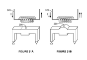
- FIGS. 21A and 21B are schematic representations of the first subassembly (bottom) coupled to the second subassembly 300 (top), wherein the second subassembly 300 includes a second embodiment of an electromagnetic actuator, shown in a retracted state and an extended state, respectively.
- the pump assembly of the present invention includes a first subassembly 200 that pumps a liquid reactant from a liquid reactant dispenser to a reaction chamber, and a second subassembly 300 that induces pumping within the first subassembly 200 , wherein the first subassembly substantially isolates the liquid reactant from the second subassembly 300 .
- the pump assembly is preferably incorporated into a fuel cell system 100 including a fuel generator 120 and a fuel cell arrangement 140 , and is preferably used to move a liquid reactant 244 within the fuel generator 120 without exposing the liquid reactant 244 to other system components.
- the liquid reactant 244 is preferably isolated within the fuel generator 120 throughout the entire pumping process.
- the pump assembly of the present invention may present several advantages. First, by isolating the fluid-contacting components within the first subassembly 200 , the fuel generator 120 (which incorporates the first subassembly 200 ) may be made at a substantially low enough cost to be a single use disposable product.
- the pump assembly preferably forms a positive displacement pump, but may alternatively include an axial flow pump, a gravity pump, an electro-osmosis pump, or any other pump wherein the fluid-contacting components may be isolated from the actuating components.
- the fuel cell system 100 that utilizes the pump assembly preferably includes a fuel generator 120 and a fuel cell arrangement 140 .
- the fuel cell system 100 is preferably a hydrogen fuel cell system 100 , but may alternatively be any other system that converts a fuel into electricity.
- the fuel cell arrangement 140 is preferably any fuel cell arrangement (with one or more fuel cells arranged in a stack, in series, in parallel, etc.) that converts hydrogen gas to electricity, but may alternatively convert any other type of fuel to electricity.
- the fuel generator 120 is preferably a hydrogen generator (e.g. a sodium borohydride hydrogen generator or an aluminum hydride hydrogen generator), but may alternatively be any other fuel generator 120 . As shown in FIG.
- the fuel generator 120 preferably contains a liquid reactant 244 , contained in a liquid storage area, and a solid reactant, contained in a reaction area, wherein the liquid reactant 244 is pumped to the reaction area to react with the solid reactant and produce hydrogen gas and waste products, which are passed through a product collection area 122 that filters out the hydrogen gas.
- the liquid reactant 244 is preferably an acid solution (e.g. citric acid or sulfuric acid), more preferably a diluted acid-water solution, but may alternatively be an anti-freeze solution (ethylene glycol, propyl glycol), combination thereof, or water.
- the solid reactant preferably includes sodium borohydride, but may alternatively include aluminum hydride or any suitable hydrogen storage material that reacts to produce hydrogen.
- substantially all fluid except the fuel should be contained inside the fuel generator 120 at all times during the operation of the fuel generator 120 .
- the fuel is preferably the only fluid allowed to flow out of the fuel generator 120 , and preferably substantially flows into the fuel cell arrangement 140 from an outlet 124 in the fuel generator 120 to an inlet 144 in the fuel cell arrangement 140 , wherein the fuel generator 120 outlet 124 and fuel cell inlet 144 are fluidly coupled.
- the first subassembly 200 of the pump includes an inlet 240 , an outlet 260 , a fluid conduit 210 , a diaphragm 220 , and an actuation point 280 .
- the first subassembly 200 functions to pump a liquid reactant 244 from a liquid reactant storage area 242 to a reaction area containing a second reactant.
- the first subassembly 200 is preferably incorporated into a hydrogen generator (e.g. a sodium borohydride or aluminum hydride system), but may alternatively be incorporated into or removably coupled to any fuel generator 120 .
- the first subassembly 200 functions to isolate the liquid reactant 244 within the hydrogen generator, wherein the pumped liquid reactant 244 is substantially retained within the hydrogen generator during the pumping process.
- the inlet 240 of the first subassembly 200 functions to fluidly couple the fluid conduit 210 to the liquid reactant 244 in the liquid reactant storage area 242 .
- the inlet 240 is preferably a portion of a tube 246 located within the liquid reactant storage area 242 , but may alternatively be a wick or membrane fluidly coupled to a liquid reactant storage area outlet 260 .
- the inlet 240 preferably includes a passive, one-way valve 248 that allows fluid flow out of the liquid reactant storage area 242 and prevents fluid flow into the liquid reactant storage area 242 .
- the inlet 240 may alternately include an active one-way valve, an active two-way valve, or no valves at all.
- the first subassembly preferably includes one inlet 240 , but may alternatively include any suitable number of inlets.
- the outlet 260 of the first subassembly 200 functions to fluidly couple the fluid conduit 210 to the reaction area and to transfer liquid reactant 244 from the first subassembly 200 to the reaction area.
- the outlet 260 is preferably a nozzle 266 located within the reaction area 262 proximal to the solid reactant, but may alternatively be a tube or wick fluidly coupled to the inlet 240 of the reaction area.
- the outlet 260 preferably includes a passive, one-way valve 264 that allows fluid flow out of the first subassembly 200 and prevents fluid flow into the first subassembly 200 .
- the outlet 260 may alternately include an active one-way valve, an active two-way valve, or no valves at all.
- the first subassembly preferably includes one outlet, but may alternatively include two outlets, three outlets, or any number of outlets, wherein the additional outlets may be disposed in the reaction area or in other areas of the fuel generator 120 (e.g. a product collection area or the outlet of the reaction area).
- the fluid conduit 210 of the first subassembly functions to contain the packet of liquid reactant being pumped, and may cooperate with the diaphragm to generate the pumping pressures.
- the fluid conduit 210 is preferably a pumping chamber, but may alternatively be a tube.
- the fluid conduit 210 is fluidly coupled to the diaphragm, the inlet(s) and the outlet(s).
- the diaphragm preferably defines a portion of the fluid conduit 210 , more preferably a wall of the fluid conduit 210 .
- the inlet and outlet are preferably positioned on opposing sides of the fluid conduit 210 , but may alternatively be positioned in any suitable position.
- the fluid conduit 210 is a substantially rigid prismatic pumping chamber, wherein the diaphragm forms the chamber wall most proximal to the first subassembly exterior, the inlet is located on a wall adjacent the diaphragm, and the outlet is located on a wall opposing the inlet.
- the fluid conduit 210 is a substantially flexible tube, wherein the diaphragm is a longitudinal portion of the tube and the first and second ends of the tube form the inlet and outlet, respectively.
- the first subassembly 200 preferably includes one fluid conduit 210 , but may alternatively include any suitable number of fluid conduit 210 s.
- the diaphragm 220 of the first subassembly 200 functions to pump a packet of liquid reactant 244 from the inlet 240 to the outlet 260 through the fluid conduit 210 .
- the diaphragm 220 is preferably fluidly coupled to the fluid conduit 210 , the inlet 240 , and the outlet 260 , and is preferably located between the inlet valve and the outlet valve.
- the diaphragm 220 is preferably disposed near the exterior of the first subassembly 200 , more preferably near the exterior of the fuel generator 120 . However, the diaphragm 220 may alternately be disposed toward the interior of the first subassembly 200 .
- the diaphragm 220 preferably includes a piece of flexible material 222 fluidly coupled to fluid conduit 210 , wherein flexion of the diaphragm 220 toward the interior of the fluid conduit 210 (flexed state) creates a positive pressure that forces any liquid reactant 244 contained within the fluid conduit 210 through the outlet (preferably the outlet valve), and relaxation of the diaphragm 220 (unflexed state) creates a negative pressure that pulls liquid reactant 244 through the inlet (preferably the inlet valve) into the fluid conduit 210 .
- the diaphragm 220 may include a piece of flexible material 222 fluidly coupled to the fluid conduit 210 , wherein flexion of the diaphragm 220 toward the exterior of the first subassembly 200 creates a negative pressure that pulls liquid reactant 244 through the inlet valve and relaxation or flexion of the diaphragm 220 toward the interior of the first subassembly 200 pushes liquid reactant 244 through the outlet valve.
- the diaphragm 220 may also include a section of flexible tubing 224 , wherein the tubing fluidly couples the inlet 240 to the outlet 260 .
- the diaphragm 220 may move packets of liquid reactant 244 by being periodically radially occluded, wherein the radial occlusion moves to push liquid reactant 244 out of the outlet 260 and pull liquid reactant 244 in through the inlet 240 (e.g. via peristaltic pumping).
- the radial occlusion is preferably accomplished by flexing a portion of the diaphragm 220 toward the opposing wall of the diaphragm 220 .
- Reciprocation of the diaphragm 220 is preferably achieved by repeated flexion of the diaphragm 220 .
- the diaphragm may alternatively be a substantially rigid conduit (e.g.
- the diaphragm 220 is preferably made from a polymer, and more preferably a polymer with a high melting temperature to withstand the high temperatures generated by the liquid- and solid-reactant reaction.
- the diaphragm 220 may additionally or alternatively include metal, such as a metal sheet or metal lining. Examples of materials that the diaphragm 220 may be made of include silicone rubber, polyethylene, PVC, PEEK, PTFE, aluminum, copper, cobalt, nitinol, magnetite, etc.
- the actuation point 280 of the first subassembly 200 functions to couple with the second subassembly 300 to facilitate liquid reactant pumping from the inlet 240 to the outlet 260 .
- the actuation point 280 is preferably positioned on the diaphragm 220 , and more preferably forms a portion of the diaphragm, such that components of the second subassembly 300 directly contact the diaphragm 220 .
- the actuation point 280 may alternatively be located on an auxiliary component 290 , contained within the first subassembly 200 , wherein the second subassembly 300 actuates the auxiliary component 290 , which actuates the diaphragm 220 .
- the auxiliary component 290 may additionally include a return element 292 that returns the auxiliary component 290 to a resting position that allows the diaphragm 220 to be in an unflexed state.
- the auxiliary component 290 is preferably a rod slidably coupled to both the diaphragm 220 and the exterior of the first subassembly 200 , more preferably to the exterior of the fuel generator 120 , wherein the actuation point 280 is on the end of the rod distal to the diaphragm 220 , such that the second subassembly 300 linearly actuates the rod to extend and retract, flexing and unflexing the diaphragm 220 , respectively.
- the rod preferably further includes a spring as a return element 292 , allowing the rod to retract back to a resting position (as shown in FIGS.
- the rod is preferably mechanically coupled to the diaphragm 220 and the second subassembly 300 , such that a force applied against the rod by the second subassembly 300 translates to a force that flexes the diaphragm 220 .
- the rod may also be magnetically coupled to the second subassembly 300 and mechanically coupled to the diaphragm 220 , wherein a change in the magnetic field of the second assembly results in linear translation of the rod against the diaphragm 220 , flexing the diaphragm.
- the auxiliary component 290 may alternately not include a rod at all, but be a piece of magnetic material 291 coupled to the diaphragm 220 such that changes in a magnetic field applied by the second subassembly 300 results in movement of the diaphragm 220 as the magnetic material responds to the changes.
- the elasticity of the diaphragm 220 is preferably the return element 292 , but a spring or set of springs may also be disposed on the diaphragm 220 to cause it to return to an unflexed state when not in operation.
- the auxiliary component 290 may alternately be a rotor 294 , wherein the actuation point 280 is substantially in the center of the rotor 294 end face and the diaphragm 220 is slidably disposed about a portion of the rotor circumference 296 , such that the diaphragm 220 substantially contacts the portion of the rotor circumference for a majority of the operation time.
- a separate actuator contained within the fuel cell system, preferably actuates the rotor 294 .
- the rotor 294 preferably includes one or more rollers 297 disposed on the exterior of the rotor about the rotor circumference, such that the rollers 297 protrude radially from the rotor 294 , wherein the rollers 297 rotate with the rotor 294 .
- This embodiment is preferably used with the tube 224 embodiment of the diaphragm 220 .
- this embodiment may additionally include a position retention (e.g.
- This embodiment may additionally include a return element 292 that removes the couple between the rotor 294 and the diaphragm 220 when not coupled to the second subassembly 300 .
- a return mechanism is a set of springs coupled to the interior rotor end face (the rotor 294 end face furthest from the exterior of the first subassembly 200 ).
- springs are preferably soft enough to be easily compressed when the first subassembly 200 is coupled to the second subassembly 300 , but are stiff enough to push the rotor 294 out of the operative plane of rotation when the first subassembly 200 is decoupled from the second subassembly 300 , effectively removing the couple between the rotor 294 and the diaphragm 220 when the fuel cell system 100 is not in operation.
- the rotor and diaphragm couple is preferably maintained when the fuel cell system 100 is not in operation.
- both rotor 294 and the roller protrusion are part of the second assembly, effectively removing the coupling between the rotor and the diaphragm 220 when the fuel cell system 100 is not in operation.
- the auxiliary component 290 is a concave groove 298 disposed on the side of the diaphragm 220 most interior to the first subassembly 200 , such that the auxiliary component 290 is concave toward the exterior of the first subassembly 200 and the diaphragm 220 is disposed between the auxiliary component 290 and the exterior of the first subassembly 200 .
- This auxiliary component embodiment is preferably used with the tube embodiment of the diaphragm 220 .
- the entire auxiliary component 290 is the actuation point 280 , wherein a component of the second subassembly 300 compresses a portion of the diaphragm 220 to occlude the diaphragm against the auxiliary component 290 (groove 298 ).
- the auxiliary component 290 includes a pair of electrical contacts (electrodes) contacting the diaphragm 220 , more preferably contacting the diaphragm near the inlet 240 and outlet 260 , respectively.
- the negative electrode is preferably located near the inlet and the positive electrode near the outlet, but the electrode pair may have any other suitable orientation or positioning.
- This auxiliary component 290 is preferably utilized with the electro-osmosis embodiment of the diaphragm 220 .
- the auxiliary component preferably electrically couples the actuator, wherein the voltage between the electrode pair is brought to the same voltage as the actuator, effectively applying a voltage over the diaphragm 220 to pump the liquid reactant from the inlet to the outlet.
- the second subassembly 300 of the pump includes an actuator 320 that functions to effect pumping within the first subassembly 200 .
- the actuator 320 preferably functions to actuate the flexion of the diaphragm 220 , but may alternatively effect pumping in any suitable manner.
- the second subassembly 300 may additionally include a translational member, which functions to mechanically translate motion from the actuator 320 to the actuation point 280 .
- the second subassembly 300 is preferably incorporated into a fuel cell arrangement 140 , but may alternatively be clipped, plugged, or otherwise coupled to a fuel cell. Alternately, the second subassembly 300 may be a stand-alone component and not be incorporated with any component of the fuel cell system 100 .
- the fuel stack preferably converts hydrogen gas to electricity, but may alternatively convert any other fuel to electricity.
- the actuator 320 of the second subassembly 300 functions to actuate the diaphragm 220 in the first subassembly 200 . This actuation is preferably achieved after the first and second subassemblies are coupled together by the connector 500 , and after a signal indicating the initiation of fuel production (e.g. a start signal) has been received.
- the actuator 320 is preferably a mechanical actuator, but may alternatively be a hydraulic actuator or an electrical actuator.
- the actuator 320 is preferably powered electrically, wherein electricity is supplied to the actuator 320 by an auxiliary power source, such as a rechargeable battery 400 (shown in FIG. 5 ).
- the actuator 320 preferably actuates a translational member 340 , included in the second subassembly 300 , that physically couples with the actuation point 280 in the first subassembly 200 to reciprocate the diaphragm 220 .
- the actuator 320 is preferably a linear actuator 322 (as shown in FIGS. 15 and 16 ) that moves the translational member 340 (e.g. pump plunger 322 b ) along the longitudinal axis of the plunger 322 b , but may alternatively be a rotational actuator that rotates the translational member 340 about the rotational axis of the translational member 340 .
- the linear actuator 322 is preferably used to actuate the diaphragm 220 directly, wherein the translational member 340 extends to flex the diaphragm 220 , and retracts to relax the diaphragm 220 .
- the translational member 340 preferably substantially contacts the diaphragm 220 throughout the pumping cycle, but may alternatively only contact the diaphragm 220 when flexing the diaphragm 220 .
- the linear actuator 322 may also be used with the rod embodiment of the auxiliary component 290 , wherein the translational member 340 couples to the end of the rod distal from the diaphragm 220 (actuation point).
- the rotational actuator is preferably used with the rotor embodiment of the auxiliary component 290 , wherein the translational member 340 couples with the rotating axis of the rotor (the auxiliary component) at the actuation point 286 , or with the grooved embodiment 298 of the auxiliary component 290 , wherein the translational member 340 couples with the groove 288 .
- the translational member 340 is preferably capable of extending past the exterior of the second subassembly 300 , and is preferably a rod 342 with actuation point-coupling features (e.g.
- the actuator 320 may alternatively directly actuate the diaphragm 220 by coupling electromagnetically with the actuation point 280 , without the use of a translational member 340 , or may be electrical couples (electrodes) held at a predetermined voltage, wherein the actuator couples to the electrode pair (auxiliary component) of the first subassembly (e.g. the fifth embodiment).
- the actuator may alternatively be any suitable actuator that interacts with the first subassembly to induce liquid reactant pumping within the first subassembly.
- actuation is achieved by contraction and extension of a shape memory alloy wire connected to a plunger 322 b head located at the proximal end of the pump plunger 322 b (the translational member 340 ), wherein the pump plunger 322 b extends to push against the actuation point 280 of the first subassembly 200 .
- the shape memory alloy wire is included of a shape memory alloy material, such as a nickel-titanium alloy popularly known as “nitinol”. The shape memory alloy material is sensitive to temperature or heat.
- nitinol temporarily shrinks at a range of temperatures dictated by the composition of the nitinol will expand at a relative lower temperature and return to its original condition.
- the nitinol alloy undergoes a dimensional change, such as a change in its length.
- the nitinol wire 322 a can undergo a reduction in length and return to its original length repeatedly via repeated temperature cycling above its shrinkage temperature and cooling to below its expansion temperature.
- the nitinol wire 322 a is threaded through the plunger 322 b head and attached at either end to the second subassembly 300 by crimp connections.
- the nitinol wire 322 a is located such that when in its contracted phase, the plunger 322 b head is in its retracted position; when the nitinol wire 322 a is in its expanded phase, the plunger 322 b head is in its fully extended position.
- the crimp connections are connected to electrical wire that is electrically coupled to a rechargeable battery 400 .
- linear motion of the translational member 340 is achieved by slidably coupling the translational member 340 to the circumferential surface 325 of a rotating cam 324 , wherein a part of the cam 324 strikes the translational member 340 at one or more points on its circular path to extend the translational member 340 partially out of the second subassembly 300 .
- This is preferably accomplished by using a circular cam 324 wherein the axis of rotation is offset from the center of the cam 326 , such that rotation of the cam 324 produces an ellipsoidal rotational path 327 .
- the translational member 340 is preferably slidably constrained within the second subassembly 300 , such that it can only vary between a fully extended (past the exterior of the second subassembly 300 ) and fully retracted (contained within the second subassembly 300 ) state, wherein the translational member 340 extends and retracts along its longitudinal axis.
- the translational member 340 is coupled to the cam 324 such that the translational member 340 is extended past the second subassembly 300 when the rotational path of the cam reaches a vertex at the couple, and is retracted into the second subassembly 300 when the rotational path of the cam 324 reaches a minor axis at the couple.
- the cam itself may have an eccentric profile that extends the translational member 340 past the exterior of the second subassembly 300 at a point during the cam rotation, as shown in FIGS. 12A and 12B .
- linear motion of the translational member 340 is achieved by utilizing a linear actuator 322 including a shape memory component, more preferably a Nitinol wire 322 a , and a rotating arm coupled to a rod 342 .
- the Nitinol wire 322 a is preferably connected to an electrical supply and to an end of the rotating arm.
- the rotating arm is preferably a rigid member, wherein one end of the rotating arm is preferably coupled to the Nitinol wire 322 a , and the other end preferably coupled to the rod 342 end at actuation point 284 , preferably through the side of the rod 342 .
- the rotating arm preferably rotates about a point disposed along its length, wherein the rotation point is preferably disposed near the center of the rotating arm length.
- the wire expands, pushing the end of the rotating arm coupled to the Nitinol wire 322 a away from its equilibrium position (the position that the rotating arm is in when the Nitinol wire 322 a is not heated).
- This movement rotates the rotating arm about its rotation point to move actuation point 284 , thereby translating the rod 342 along the rod's linear axis.
- the second assembly preferably further includes a guide that constrains the rod to move only along its linear axis.
- the linear actuator 322 may additionally or alternatively be a piezoelectric driver (shown in FIGS. 14A and 14B ), a rack and pinion (wherein the actuator 320 drives the pinion, and the translational member 340 is the rack), a lead screw (shown in FIGS. 15A and 15B ), a worm-gear (shown in FIGS. 16A and 16B ), a belt drive, a two-bar linkage coupled to a cam (shown in FIGS. 17A and 17B ), or any other type of actuator 320 that can extend and retract a translational member 340 along its longitudinal axis. Additionally, the translational member 340 may have additional physical properties, such as magnetic properties or piezoelectric properties.
- a stepper motor is coupled to a translational member 340 with a magnet at the distal end (i.e. end not coupled to the stepper motor).
- This embodiment is preferably used with an embodiment of the first subassembly 200 that incorporates magnetic elements (e.g. the diaphragm 220 incorporating a magnetic metal sheet), wherein the magnetic element of the diaphragm 220 is repelled by the translational member 340 such that extension of the translational member 340 repels the diaphragm 220 , causing it to flex.
- rotational motion of the translational member is achieved by coupling the translational member to a rotating motor, such as a drill motor, a DC motor, or an AC motor.
- the translational member is preferably a rod, and is preferably coupled to the actuator such that rotation of the actuator rotates the translational member around the longitudinal axis of the translational member 340 .
- the translational member preferably mechanically couples to the rotational axis of the rotor embodiment of the auxiliary component 294 (in the first subassembly 200 ), such that rotation of the translational member rotates the rotor 294 .
- rotational motion of the translational member is achieved by coupling the translational member to a rotating motor, such as a drill motor, a DC motor, or an AC motor.
- the translational member is preferably an eccentric rotor and is preferably coupled to the actuator 320 through the end faces of the rotor, such that rotation of the actuator 320 rotates the rotor in a plane parallel to the planes of the end faces.
- the translational member preferably couples to the groove 298 embodiment of the auxiliary component 290 , wherein the eccentric (i.e. protruding) portion of the rotor slides along the length of the groove 298 during a portion of the rotor rotation.
- the eccentric portion of the rotor occludes the diaphragm 220 when it couples with the groove 298 , effectively occluding the diaphragm 220 to push any fluid in the direction of rotation.
- the actuator 320 preferably rotates the rotor in the direction of the reaction chamber, such that liquid reactant 244 is pushed toward the reaction chamber.
- the actuator is a mechanism capable of producing a changing magnetic field. More preferably, the actuator is a mechanism that can change the direction of a magnetic field, such as a solenoid.
- This actuator is preferably used with a magnetic embodiment of the first subassembly 200 (e.g. the diaphragm 220 incorporating a magnetic sheet or the magnetic rod embodiment of the auxiliary component 290 ).
- the actuator 320 repels the magnetic element of the first subassembly with a first generated electromagnetic field, and attracts the magnetic element with a second generated electromagnetic field, wherein the first and second electromagnetic fields are opposing magnetic fields. Cycling between the first and second electromagnetic fields results in reciprocation of the diaphragm 220 .
- the actuator is a mechanism capable of producing a changing magnetic field. More specifically, the actuator is a mechanism capable of changing the magnitude of the magnetic field.
- This actuator is preferably used with a magnetic embodiment of the first subassembly 200 (e.g. the diaphragm 220 incorporating a magnetic sheet 294 or the magnetic rod embodiment of the auxiliary component 290 ) further incorporating a return element 292 that allows return of the diaphragm 220 to an equilibrium position (e.g. the elasticity of the diaphragm 220 , a spring coupled to the magnetic rod).
- the actuator 320 either repels or attracts the magnetic element of the first subassembly 200 with a first generated electromagnetic field, then lowers the magnitude of the generated field to a second generated electromagnetic field to allow the return element 292 to return the diaphragm 220 to the equilibrium position. Cycling the generated field between a strong and weak field results in reciprocation of the diaphragm 220 .
- the first and second fields may have opposing directions, or differ in any other suitable parameter.
- the connector 500 of the pump assembly functions to removably couple the first subassembly 200 to the second subassembly 300 .
- the connector 500 preferably utilizes a magnetic couple, wherein the second subassembly 300 includes a magnet that is magnetically attracted to a metal plate included within the first subassembly 200 .
- the connector 500 may alternately be a mechanical couple, wherein the first subassembly 200 includes a protrusion that slides into and removably clips into a groove in the second subassembly 300 (e.g. a tongue and groove joint).
- Other examples of mechanical couples include hooks, clips, adherent, screws, or any other suitable couple that removably couples the first subassembly 200 to the second subassembly 300 .
Abstract
A method of supplying fuel to a fuel cell system wherein a flexible diaphragm controls ingress and egress of liquid reactant. The method utilizes a pump assembly including a first subassembly and a second subassembly. The first subassembly includes a fluid conduit; an inlet fluidly coupled to the liquid reactant dispenser and the fluid conduit; an outlet fluidly coupled to a reaction chamber and the fluid conduit; and a diaphragm, defining a portion of the fluid conduit, that flexes to pump the liquid reactant from the inlet to the outlet. The diaphragm preferably includes an actuation point coupled to the diaphragm, wherein the liquid reactant is substantially contained within the first subassembly during pumping. The second subassembly is couplable to the first subassembly, and is fluidly isolated from the liquid reactant wherein operation of the actuator causes diaphragm flexion.
Description
This application is a continuation of U.S. patent application Ser. No. 14/297,509, filed Jun. 5, 2014 and issued as U.S. Pat. No. 9,142,849 on Sep. 22, 2015, which is a continuation of U.S. patent application Ser. No. 13/286,044, filed Oct. 31, 2011 and issued as U.S. Pat. No. 8,795,926 on Aug. 5, 2014, the contents of which are incorporated by reference in their entirety. U.S. patent application Ser. No. 13/286,044 is a continuation-in-part of U.S. patent application Ser. No. 11/203,001, filed on Aug. 11, 2005 and issued as U.S. Pat. No. 8,187,758 on May 29, 2012, and also claims priority to U.S. Provisional Patent Application Ser. No. 61/408,462, filed on Oct. 29, 2010, the contents of each of which are incorporated by reference herein in their entireties.
This invention relates generally to the fuel cell field, and more specifically to a pump assembly for a fuel cell system.
Modern portable electronic devices are demanding increasing amounts of electrical power and chemical batteries are often the performance bottleneck for such devices. Wireless products, such as personal digital assistants, mobile phones, entertainment devices, and next generation laptops in particular have a great demand for sustained power. For long-term portable operations, fuel cells are an attractive solution. Fuel cells, like batteries, efficiently convert chemical energy into electricity, but have additional advantages, such as higher energy density and the capability for instant refueling. Fuel cells are typically fuelled by hydrogen gas, but there are technological challenges in storing and delivering hydrogen gas to the fuel cells in a cost effective and efficient manner. One particular challenge is to provide a fuel supply that is inexpensive, safe, light and compact enough to be readily portable yet store enough hydrogen to provide a useful amount of fuel to the fuel cell. State of the art means for storing hydrogen include metal hydride canisters to store hydrogen at relatively low pressures, and pressure tanks to store compressed hydrogen at elevated pressures. Both approaches have drawbacks; for example, metal hydride storage is relatively safe but has a low energy density to weight ratio, and compressed hydrogen may have a high energy density to weight ratio but requires high strength and expensive containment solutions.
Other efforts have been directed at generating hydrogen gas from a hydrogen-containing fuel precursor such as sodium borohydride. In such approaches, the fuel solution is exposed to a reactant to facilitate the production of hydrogen gas. This reactant is typically a liquid reactant that must be pumped to a reaction site. In conventional systems, the pump is either be placed within the fuel generator or within the fuel cell system. Placement of the pump within fuel generator allows for a simple fluid interface, requiring only a fuel outlet, but also increases the cost of the fuel generator, which is typically a disposable component and thus, cost sensitive. Placement of the pump within the fuel cell system decreases the cost of the fuel generator, but adds the technical complexities of managing multiple fluid ports, as the liquid reactant must be pumped into the fuel cell system and back into the fuel generator.
Therefore, there exists a need for a better pump assembly in the fuel cell system to pump liquid reactant to the reaction site. More specifically, there exists a need for a pump assembly that splits the pump actuator from the fluid-contacting components, effectively decreasing the cost of fuel generator while minimizing the technical complexities of the system arising from multiple fluid ports.
The following description of the preferred embodiments of the invention is not intended to limit the invention to these preferred embodiments, but rather to enable any person skilled in the art to make and use this invention.
As shown in FIG. 1 , the pump assembly of the present invention includes a first subassembly 200 that pumps a liquid reactant from a liquid reactant dispenser to a reaction chamber, and a second subassembly 300 that induces pumping within the first subassembly 200, wherein the first subassembly substantially isolates the liquid reactant from the second subassembly 300. The pump assembly is preferably incorporated into a fuel cell system 100 including a fuel generator 120 and a fuel cell arrangement 140, and is preferably used to move a liquid reactant 244 within the fuel generator 120 without exposing the liquid reactant 244 to other system components. In other words, the liquid reactant 244 is preferably isolated within the fuel generator 120 throughout the entire pumping process. This is preferably accomplished by isolating the fluid-contacting components within a first subassembly 200 and by isolating all other components (particularly the actuating components) of the pump within a second subassembly 300, wherein the first subassembly 200 is incorporated within the fuel generator 120 and the second subassembly 300 is incorporated within the fuel cell arrangement 140. In doing so, the pump assembly of the present invention may present several advantages. First, by isolating the fluid-contacting components within the first subassembly 200, the fuel generator 120 (which incorporates the first subassembly 200) may be made at a substantially low enough cost to be a single use disposable product. Secondly, by retaining the reactants entirely within the first subassembly 200 (and therefore the fuel generator 120), chances of leakage and subsequent damage to a user or surrounding equipment may be reduced. The pump assembly preferably forms a positive displacement pump, but may alternatively include an axial flow pump, a gravity pump, an electro-osmosis pump, or any other pump wherein the fluid-contacting components may be isolated from the actuating components.
The fuel cell system 100 that utilizes the pump assembly preferably includes a fuel generator 120 and a fuel cell arrangement 140. The fuel cell system 100 is preferably a hydrogen fuel cell system 100, but may alternatively be any other system that converts a fuel into electricity. Likewise, as shown in FIG. 3 , the fuel cell arrangement 140 is preferably any fuel cell arrangement (with one or more fuel cells arranged in a stack, in series, in parallel, etc.) that converts hydrogen gas to electricity, but may alternatively convert any other type of fuel to electricity. Similarly, the fuel generator 120 is preferably a hydrogen generator (e.g. a sodium borohydride hydrogen generator or an aluminum hydride hydrogen generator), but may alternatively be any other fuel generator 120. As shown in FIG. 2 , the fuel generator 120 preferably contains a liquid reactant 244, contained in a liquid storage area, and a solid reactant, contained in a reaction area, wherein the liquid reactant 244 is pumped to the reaction area to react with the solid reactant and produce hydrogen gas and waste products, which are passed through a product collection area 122 that filters out the hydrogen gas. The liquid reactant 244 is preferably an acid solution (e.g. citric acid or sulfuric acid), more preferably a diluted acid-water solution, but may alternatively be an anti-freeze solution (ethylene glycol, propyl glycol), combination thereof, or water. The solid reactant preferably includes sodium borohydride, but may alternatively include aluminum hydride or any suitable hydrogen storage material that reacts to produce hydrogen. By using the pump assembly of the present invention, substantially all fluid except the fuel (e.g. H2 gas) should be contained inside the fuel generator 120 at all times during the operation of the fuel generator 120. The fuel is preferably the only fluid allowed to flow out of the fuel generator 120, and preferably substantially flows into the fuel cell arrangement 140 from an outlet 124 in the fuel generator 120 to an inlet 144 in the fuel cell arrangement 140, wherein the fuel generator 120 outlet 124 and fuel cell inlet 144 are fluidly coupled.
The First Subassembly
As shown in FIG. 4 , the first subassembly 200 of the pump includes an inlet 240, an outlet 260, a fluid conduit 210, a diaphragm 220, and an actuation point 280. The first subassembly 200 functions to pump a liquid reactant 244 from a liquid reactant storage area 242 to a reaction area containing a second reactant. The first subassembly 200 is preferably incorporated into a hydrogen generator (e.g. a sodium borohydride or aluminum hydride system), but may alternatively be incorporated into or removably coupled to any fuel generator 120. Furthermore, the first subassembly 200 functions to isolate the liquid reactant 244 within the hydrogen generator, wherein the pumped liquid reactant 244 is substantially retained within the hydrogen generator during the pumping process.
The inlet 240 of the first subassembly 200 functions to fluidly couple the fluid conduit 210 to the liquid reactant 244 in the liquid reactant storage area 242. The inlet 240 is preferably a portion of a tube 246 located within the liquid reactant storage area 242, but may alternatively be a wick or membrane fluidly coupled to a liquid reactant storage area outlet 260. The inlet 240 preferably includes a passive, one-way valve 248 that allows fluid flow out of the liquid reactant storage area 242 and prevents fluid flow into the liquid reactant storage area 242. However, the inlet 240 may alternately include an active one-way valve, an active two-way valve, or no valves at all. The first subassembly preferably includes one inlet 240, but may alternatively include any suitable number of inlets.
The outlet 260 of the first subassembly 200 functions to fluidly couple the fluid conduit 210 to the reaction area and to transfer liquid reactant 244 from the first subassembly 200 to the reaction area. The outlet 260 is preferably a nozzle 266 located within the reaction area 262 proximal to the solid reactant, but may alternatively be a tube or wick fluidly coupled to the inlet 240 of the reaction area. The outlet 260 preferably includes a passive, one-way valve 264 that allows fluid flow out of the first subassembly 200 and prevents fluid flow into the first subassembly 200. However, the outlet 260 may alternately include an active one-way valve, an active two-way valve, or no valves at all. The first subassembly preferably includes one outlet, but may alternatively include two outlets, three outlets, or any number of outlets, wherein the additional outlets may be disposed in the reaction area or in other areas of the fuel generator 120 (e.g. a product collection area or the outlet of the reaction area).
The fluid conduit 210 of the first subassembly functions to contain the packet of liquid reactant being pumped, and may cooperate with the diaphragm to generate the pumping pressures. The fluid conduit 210 is preferably a pumping chamber, but may alternatively be a tube. The fluid conduit 210 is fluidly coupled to the diaphragm, the inlet(s) and the outlet(s). The diaphragm preferably defines a portion of the fluid conduit 210, more preferably a wall of the fluid conduit 210. The inlet and outlet are preferably positioned on opposing sides of the fluid conduit 210, but may alternatively be positioned in any suitable position. In one specific embodiment, the fluid conduit 210 is a substantially rigid prismatic pumping chamber, wherein the diaphragm forms the chamber wall most proximal to the first subassembly exterior, the inlet is located on a wall adjacent the diaphragm, and the outlet is located on a wall opposing the inlet. In a second specific embodiment, the fluid conduit 210 is a substantially flexible tube, wherein the diaphragm is a longitudinal portion of the tube and the first and second ends of the tube form the inlet and outlet, respectively. The first subassembly 200 preferably includes one fluid conduit 210, but may alternatively include any suitable number of fluid conduit 210 s.
The diaphragm 220 of the first subassembly 200 functions to pump a packet of liquid reactant 244 from the inlet 240 to the outlet 260 through the fluid conduit 210. The diaphragm 220 is preferably fluidly coupled to the fluid conduit 210, the inlet 240, and the outlet 260, and is preferably located between the inlet valve and the outlet valve. The diaphragm 220 is preferably disposed near the exterior of the first subassembly 200, more preferably near the exterior of the fuel generator 120. However, the diaphragm 220 may alternately be disposed toward the interior of the first subassembly 200. The diaphragm 220 preferably includes a piece of flexible material 222 fluidly coupled to fluid conduit 210, wherein flexion of the diaphragm 220 toward the interior of the fluid conduit 210 (flexed state) creates a positive pressure that forces any liquid reactant 244 contained within the fluid conduit 210 through the outlet (preferably the outlet valve), and relaxation of the diaphragm 220 (unflexed state) creates a negative pressure that pulls liquid reactant 244 through the inlet (preferably the inlet valve) into the fluid conduit 210. Alternately, the diaphragm 220 may include a piece of flexible material 222 fluidly coupled to the fluid conduit 210, wherein flexion of the diaphragm 220 toward the exterior of the first subassembly 200 creates a negative pressure that pulls liquid reactant 244 through the inlet valve and relaxation or flexion of the diaphragm 220 toward the interior of the first subassembly 200 pushes liquid reactant 244 through the outlet valve. The diaphragm 220 may also include a section of flexible tubing 224, wherein the tubing fluidly couples the inlet 240 to the outlet 260. In this case, the diaphragm 220 may move packets of liquid reactant 244 by being periodically radially occluded, wherein the radial occlusion moves to push liquid reactant 244 out of the outlet 260 and pull liquid reactant 244 in through the inlet 240 (e.g. via peristaltic pumping). The radial occlusion is preferably accomplished by flexing a portion of the diaphragm 220 toward the opposing wall of the diaphragm 220. Reciprocation of the diaphragm 220 is preferably achieved by repeated flexion of the diaphragm 220. However, the diaphragm may alternatively be a substantially rigid conduit (e.g. a porous material, capillary tube, membrane, microchannel, etc.), wherein the diaphragm facilitates the movement of liquid reactant through the diaphragm when a voltage is applied across the diaphragm, preferably to the inlet and outlet (e.g. via electro-osmosis). The diaphragm 220 is preferably made from a polymer, and more preferably a polymer with a high melting temperature to withstand the high temperatures generated by the liquid- and solid-reactant reaction. The diaphragm 220 may additionally or alternatively include metal, such as a metal sheet or metal lining. Examples of materials that the diaphragm 220 may be made of include silicone rubber, polyethylene, PVC, PEEK, PTFE, aluminum, copper, cobalt, nitinol, magnetite, etc.
The actuation point 280 of the first subassembly 200 functions to couple with the second subassembly 300 to facilitate liquid reactant pumping from the inlet 240 to the outlet 260. The actuation point 280 is preferably positioned on the diaphragm 220, and more preferably forms a portion of the diaphragm, such that components of the second subassembly 300 directly contact the diaphragm 220. However, the actuation point 280 may alternatively be located on an auxiliary component 290, contained within the first subassembly 200, wherein the second subassembly 300 actuates the auxiliary component 290, which actuates the diaphragm 220. The auxiliary component 290 may additionally include a return element 292 that returns the auxiliary component 290 to a resting position that allows the diaphragm 220 to be in an unflexed state.
In a first embodiment of the auxiliary component 290 (shown in FIGS. 6A and 6B ), the auxiliary component 290 is preferably a rod slidably coupled to both the diaphragm 220 and the exterior of the first subassembly 200, more preferably to the exterior of the fuel generator 120, wherein the actuation point 280 is on the end of the rod distal to the diaphragm 220, such that the second subassembly 300 linearly actuates the rod to extend and retract, flexing and unflexing the diaphragm 220, respectively. The rod preferably further includes a spring as a return element 292, allowing the rod to retract back to a resting position (as shown in FIGS. 7A and 7B ). In a first embodiment, the rod is preferably mechanically coupled to the diaphragm 220 and the second subassembly 300, such that a force applied against the rod by the second subassembly 300 translates to a force that flexes the diaphragm 220. However, the rod may also be magnetically coupled to the second subassembly 300 and mechanically coupled to the diaphragm 220, wherein a change in the magnetic field of the second assembly results in linear translation of the rod against the diaphragm 220, flexing the diaphragm.
In a second embodiment, as shown in FIG. 8 , the auxiliary component 290 may alternately not include a rod at all, but be a piece of magnetic material 291 coupled to the diaphragm 220 such that changes in a magnetic field applied by the second subassembly 300 results in movement of the diaphragm 220 as the magnetic material responds to the changes. In this embodiment, the elasticity of the diaphragm 220 is preferably the return element 292, but a spring or set of springs may also be disposed on the diaphragm 220 to cause it to return to an unflexed state when not in operation.
In a third embodiment, as shown in FIG. 9 , the auxiliary component 290 may alternately be a rotor 294, wherein the actuation point 280 is substantially in the center of the rotor 294 end face and the diaphragm 220 is slidably disposed about a portion of the rotor circumference 296, such that the diaphragm 220 substantially contacts the portion of the rotor circumference for a majority of the operation time. A separate actuator, contained within the fuel cell system, preferably actuates the rotor 294. In this embodiment of the auxiliary component 290, the rotor 294 preferably includes one or more rollers 297 disposed on the exterior of the rotor about the rotor circumference, such that the rollers 297 protrude radially from the rotor 294, wherein the rollers 297 rotate with the rotor 294. This embodiment is preferably used with the tube 224 embodiment of the diaphragm 220. When the roller 297 contacts the diaphragm 220 during the rotor rotation, the roller protrusion 297 pushes against the portion of the diaphragm 220 closest to the rotor 294, thereby flexing a portion of the diaphragm to occlude the diaphragm 220 (tube 224). As the rotor 294 rotates, the protrusion and occlusion move with the rotor 294, effectively pushing any fluid ahead of the occlusion in the direction of rotor rotation. As shown in FIG. 9B , this embodiment may additionally include a position retention (e.g. ratcheting mechanism) that allows only rotation away from the liquid reactant storage area 242, preventing backward rotation caused by pressure generated by the reaction between the liquid- and solid-reactants. This embodiment may additionally include a return element 292 that removes the couple between the rotor 294 and the diaphragm 220 when not coupled to the second subassembly 300. As shown in FIGS. 9C and 9D , an example of such a return mechanism is a set of springs coupled to the interior rotor end face (the rotor 294 end face furthest from the exterior of the first subassembly 200). These springs are preferably soft enough to be easily compressed when the first subassembly 200 is coupled to the second subassembly 300, but are stiff enough to push the rotor 294 out of the operative plane of rotation when the first subassembly 200 is decoupled from the second subassembly 300, effectively removing the couple between the rotor 294 and the diaphragm 220 when the fuel cell system 100 is not in operation. The rotor and diaphragm couple is preferably maintained when the fuel cell system 100 is not in operation. However, in a variation of this embodiment (shown in FIG. 18 ) both rotor 294 and the roller protrusion are part of the second assembly, effectively removing the coupling between the rotor and the diaphragm 220 when the fuel cell system 100 is not in operation.
In a fourth embodiment, as shown in FIG. 19A , the auxiliary component 290 is a concave groove 298 disposed on the side of the diaphragm 220 most interior to the first subassembly 200, such that the auxiliary component 290 is concave toward the exterior of the first subassembly 200 and the diaphragm 220 is disposed between the auxiliary component 290 and the exterior of the first subassembly 200. This auxiliary component embodiment is preferably used with the tube embodiment of the diaphragm 220. In this embodiment, the entire auxiliary component 290 is the actuation point 280, wherein a component of the second subassembly 300 compresses a portion of the diaphragm 220 to occlude the diaphragm against the auxiliary component 290 (groove 298).
In a fifth embodiment, the auxiliary component 290 includes a pair of electrical contacts (electrodes) contacting the diaphragm 220, more preferably contacting the diaphragm near the inlet 240 and outlet 260, respectively. The negative electrode is preferably located near the inlet and the positive electrode near the outlet, but the electrode pair may have any other suitable orientation or positioning. This auxiliary component 290 is preferably utilized with the electro-osmosis embodiment of the diaphragm 220. The auxiliary component preferably electrically couples the actuator, wherein the voltage between the electrode pair is brought to the same voltage as the actuator, effectively applying a voltage over the diaphragm 220 to pump the liquid reactant from the inlet to the outlet.
The Second Subassembly
The second subassembly 300 of the pump includes an actuator 320 that functions to effect pumping within the first subassembly 200. The actuator 320 preferably functions to actuate the flexion of the diaphragm 220, but may alternatively effect pumping in any suitable manner. The second subassembly 300 may additionally include a translational member, which functions to mechanically translate motion from the actuator 320 to the actuation point 280. The second subassembly 300 is preferably incorporated into a fuel cell arrangement 140, but may alternatively be clipped, plugged, or otherwise coupled to a fuel cell. Alternately, the second subassembly 300 may be a stand-alone component and not be incorporated with any component of the fuel cell system 100. The fuel stack preferably converts hydrogen gas to electricity, but may alternatively convert any other fuel to electricity.
The actuator 320 of the second subassembly 300 functions to actuate the diaphragm 220 in the first subassembly 200. This actuation is preferably achieved after the first and second subassemblies are coupled together by the connector 500, and after a signal indicating the initiation of fuel production (e.g. a start signal) has been received. The actuator 320 is preferably a mechanical actuator, but may alternatively be a hydraulic actuator or an electrical actuator. The actuator 320 is preferably powered electrically, wherein electricity is supplied to the actuator 320 by an auxiliary power source, such as a rechargeable battery 400 (shown in FIG. 5 ). To achieve actuation of the diaphragm 220, the actuator 320 preferably actuates a translational member 340, included in the second subassembly 300, that physically couples with the actuation point 280 in the first subassembly 200 to reciprocate the diaphragm 220. The actuator 320 is preferably a linear actuator 322 (as shown in FIGS. 15 and 16 ) that moves the translational member 340 (e.g. pump plunger 322 b) along the longitudinal axis of the plunger 322 b, but may alternatively be a rotational actuator that rotates the translational member 340 about the rotational axis of the translational member 340. The linear actuator 322 is preferably used to actuate the diaphragm 220 directly, wherein the translational member 340 extends to flex the diaphragm 220, and retracts to relax the diaphragm 220. The translational member 340 preferably substantially contacts the diaphragm 220 throughout the pumping cycle, but may alternatively only contact the diaphragm 220 when flexing the diaphragm 220. The linear actuator 322 may also be used with the rod embodiment of the auxiliary component 290, wherein the translational member 340 couples to the end of the rod distal from the diaphragm 220 (actuation point). The rotational actuator is preferably used with the rotor embodiment of the auxiliary component 290, wherein the translational member 340 couples with the rotating axis of the rotor (the auxiliary component) at the actuation point 286, or with the grooved embodiment 298 of the auxiliary component 290, wherein the translational member 340 couples with the groove 288. The translational member 340 is preferably capable of extending past the exterior of the second subassembly 300, and is preferably a rod 342 with actuation point-coupling features (e.g. hooks, an asymmetric end profile, or a plunger 322 b), but may alternatively be a rotor with rollers, a rod attached to a magnet, or include any feature that assists in the actuation of the translational member 340 by the actuator 320. The actuator 320 may alternatively directly actuate the diaphragm 220 by coupling electromagnetically with the actuation point 280, without the use of a translational member 340, or may be electrical couples (electrodes) held at a predetermined voltage, wherein the actuator couples to the electrode pair (auxiliary component) of the first subassembly (e.g. the fifth embodiment). The actuator may alternatively be any suitable actuator that interacts with the first subassembly to induce liquid reactant pumping within the first subassembly.
In a first embodiment of the linear actuator 322 (shown in FIGS. 10A and 10B ), actuation is achieved by contraction and extension of a shape memory alloy wire connected to a plunger 322 b head located at the proximal end of the pump plunger 322 b (the translational member 340), wherein the pump plunger 322 b extends to push against the actuation point 280 of the first subassembly 200. The shape memory alloy wire is included of a shape memory alloy material, such as a nickel-titanium alloy popularly known as “nitinol”. The shape memory alloy material is sensitive to temperature or heat. For example, nitinol temporarily shrinks at a range of temperatures dictated by the composition of the nitinol will expand at a relative lower temperature and return to its original condition. In response to being heated above this shrinkage temperature, the nitinol alloy undergoes a dimensional change, such as a change in its length. In this way, the nitinol wire 322 a can undergo a reduction in length and return to its original length repeatedly via repeated temperature cycling above its shrinkage temperature and cooling to below its expansion temperature. The nitinol wire 322 a is threaded through the plunger 322 b head and attached at either end to the second subassembly 300 by crimp connections. The nitinol wire 322 a is located such that when in its contracted phase, the plunger 322 b head is in its retracted position; when the nitinol wire 322 a is in its expanded phase, the plunger 322 b head is in its fully extended position. The crimp connections are connected to electrical wire that is electrically coupled to a rechargeable battery 400.
In a second embodiment of the linear actuator 322 (shown in FIGS. 11A and 11B ), linear motion of the translational member 340 is achieved by slidably coupling the translational member 340 to the circumferential surface 325 of a rotating cam 324, wherein a part of the cam 324 strikes the translational member 340 at one or more points on its circular path to extend the translational member 340 partially out of the second subassembly 300. This is preferably accomplished by using a circular cam 324 wherein the axis of rotation is offset from the center of the cam 326, such that rotation of the cam 324 produces an ellipsoidal rotational path 327. The translational member 340 is preferably slidably constrained within the second subassembly 300, such that it can only vary between a fully extended (past the exterior of the second subassembly 300) and fully retracted (contained within the second subassembly 300) state, wherein the translational member 340 extends and retracts along its longitudinal axis. The translational member 340 is coupled to the cam 324 such that the translational member 340 is extended past the second subassembly 300 when the rotational path of the cam reaches a vertex at the couple, and is retracted into the second subassembly 300 when the rotational path of the cam 324 reaches a minor axis at the couple. Alternately, the cam itself may have an eccentric profile that extends the translational member 340 past the exterior of the second subassembly 300 at a point during the cam rotation, as shown in FIGS. 12A and 12B .
In a third embodiment of the linear actuator (shown in FIGS. 13A and 13B ), linear motion of the translational member 340 is achieved by utilizing a linear actuator 322 including a shape memory component, more preferably a Nitinol wire 322 a, and a rotating arm coupled to a rod 342. The Nitinol wire 322 a is preferably connected to an electrical supply and to an end of the rotating arm. The rotating arm is preferably a rigid member, wherein one end of the rotating arm is preferably coupled to the Nitinol wire 322 a, and the other end preferably coupled to the rod 342 end at actuation point 284, preferably through the side of the rod 342. The rotating arm preferably rotates about a point disposed along its length, wherein the rotation point is preferably disposed near the center of the rotating arm length. Upon heating of the Nitinol wire 322 a (preferably by running a current through the wire), the wire expands, pushing the end of the rotating arm coupled to the Nitinol wire 322 a away from its equilibrium position (the position that the rotating arm is in when the Nitinol wire 322 a is not heated). This movement rotates the rotating arm about its rotation point to move actuation point 284, thereby translating the rod 342 along the rod's linear axis. However, since the force application to the rod actuation point 284 is not evenly distributed over the rod end (as the rotating arm is coupled from one side of the rod 342), the second assembly preferably further includes a guide that constrains the rod to move only along its linear axis.
The linear actuator 322 may additionally or alternatively be a piezoelectric driver (shown in FIGS. 14A and 14B ), a rack and pinion (wherein the actuator 320 drives the pinion, and the translational member 340 is the rack), a lead screw (shown in FIGS. 15A and 15B ), a worm-gear (shown in FIGS. 16A and 16B ), a belt drive, a two-bar linkage coupled to a cam (shown in FIGS. 17A and 17B ), or any other type of actuator 320 that can extend and retract a translational member 340 along its longitudinal axis. Additionally, the translational member 340 may have additional physical properties, such as magnetic properties or piezoelectric properties. For example, in an eighth embodiment of the linear actuator 322, a stepper motor is coupled to a translational member 340 with a magnet at the distal end (i.e. end not coupled to the stepper motor). This embodiment is preferably used with an embodiment of the first subassembly 200 that incorporates magnetic elements (e.g. the diaphragm 220 incorporating a magnetic metal sheet), wherein the magnetic element of the diaphragm 220 is repelled by the translational member 340 such that extension of the translational member 340 repels the diaphragm 220, causing it to flex.
In a first embodiment of the rotational actuator (shown in FIGS. 18A and 18B ), rotational motion of the translational member is achieved by coupling the translational member to a rotating motor, such as a drill motor, a DC motor, or an AC motor. In this embodiment, the translational member is preferably a rod, and is preferably coupled to the actuator such that rotation of the actuator rotates the translational member around the longitudinal axis of the translational member 340. The translational member preferably mechanically couples to the rotational axis of the rotor embodiment of the auxiliary component 294 (in the first subassembly 200), such that rotation of the translational member rotates the rotor 294.
In a second embodiment of the rotational actuator 320 (shown in FIGS. 19A and 19B ), rotational motion of the translational member is achieved by coupling the translational member to a rotating motor, such as a drill motor, a DC motor, or an AC motor. In this embodiment, the translational member is preferably an eccentric rotor and is preferably coupled to the actuator 320 through the end faces of the rotor, such that rotation of the actuator 320 rotates the rotor in a plane parallel to the planes of the end faces. The translational member preferably couples to the groove 298 embodiment of the auxiliary component 290, wherein the eccentric (i.e. protruding) portion of the rotor slides along the length of the groove 298 during a portion of the rotor rotation. Because the diaphragm 220 is preferably disposed between the groove 298 and the exterior of the first assembly when utilizing the groove 298 embodiment, the eccentric portion of the rotor occludes the diaphragm 220 when it couples with the groove 298, effectively occluding the diaphragm 220 to push any fluid in the direction of rotation. The actuator 320 preferably rotates the rotor in the direction of the reaction chamber, such that liquid reactant 244 is pushed toward the reaction chamber.
In a first embodiment of the electromagnetic actuator, the actuator is a mechanism capable of producing a changing magnetic field. More preferably, the actuator is a mechanism that can change the direction of a magnetic field, such as a solenoid. This actuator is preferably used with a magnetic embodiment of the first subassembly 200 (e.g. the diaphragm 220 incorporating a magnetic sheet or the magnetic rod embodiment of the auxiliary component 290). The actuator 320 repels the magnetic element of the first subassembly with a first generated electromagnetic field, and attracts the magnetic element with a second generated electromagnetic field, wherein the first and second electromagnetic fields are opposing magnetic fields. Cycling between the first and second electromagnetic fields results in reciprocation of the diaphragm 220.
In a second embodiment of the electromagnetic actuator, the actuator is a mechanism capable of producing a changing magnetic field. More specifically, the actuator is a mechanism capable of changing the magnitude of the magnetic field. This actuator is preferably used with a magnetic embodiment of the first subassembly 200 (e.g. the diaphragm 220 incorporating a magnetic sheet 294 or the magnetic rod embodiment of the auxiliary component 290) further incorporating a return element 292 that allows return of the diaphragm 220 to an equilibrium position (e.g. the elasticity of the diaphragm 220, a spring coupled to the magnetic rod). The actuator 320 either repels or attracts the magnetic element of the first subassembly 200 with a first generated electromagnetic field, then lowers the magnitude of the generated field to a second generated electromagnetic field to allow the return element 292 to return the diaphragm 220 to the equilibrium position. Cycling the generated field between a strong and weak field results in reciprocation of the diaphragm 220. Alternatively, the first and second fields may have opposing directions, or differ in any other suitable parameter.
As a person skilled in the art will recognize from the previous detailed description and from the figures and claims, modifications and changes can be made to the preferred embodiments of the invention without departing from the scope of this invention defined in the following claims.
The Connector
The connector 500 of the pump assembly functions to removably couple the first subassembly 200 to the second subassembly 300. The connector 500 preferably utilizes a magnetic couple, wherein the second subassembly 300 includes a magnet that is magnetically attracted to a metal plate included within the first subassembly 200. However, the connector 500 may alternately be a mechanical couple, wherein the first subassembly 200 includes a protrusion that slides into and removably clips into a groove in the second subassembly 300 (e.g. a tongue and groove joint). Other examples of mechanical couples include hooks, clips, adherent, screws, or any other suitable couple that removably couples the first subassembly 200 to the second subassembly 300.
As a person skilled in the art will recognize from the previous detailed description and from the figures and claims, modifications and changes can be made to the preferred embodiments of the invention without departing from the scope of this invention defined in the following claims.
Claims (20)
1. A method of supplying fuel to operate a fuel cell system comprising:
a fuel cartridge including a liquid reactant dispenser containing a liquid reactant and a reaction chamber distinct from the liquid reactant dispenser, a pump assembly including:
a first subassembly including: a fluid conduit, an inlet fluidly coupled to the liquid reactant dispenser and the fluid conduit, an outlet fluidly coupled to the reaction chamber and the fluid conduit, a diaphragm that defines a portion of the fluid conduit and that flexes to pump the liquid reactant from the inlet to the outlet, and an actuation point coupled to the diaphragm; wherein the liquid reactant is substantially contained within the first subassembly during pumping; and,
a second subassembly, couplable to the first subassembly and fluidly isolated from the liquid reactant, the second subassembly including an actuator that couples to the actuation point, wherein operation of the actuator causes diaphragm flexion;
flexing the diaphragm between a flexed and unflexed state; and,
wherein the flexed state creates a positive pressure within the fluid conduit so as to facilitate the egress of the liquid reactant from the outlet, and the unflexed state creates a negative pressure within the fluid conduit the facilitate ingress of liquid reactant from the inlet.
2. The method of claim 1 , the fluid conduit comprising substantially rigid prismatic pumping chamber, wherein the diaphragm forms a chamber wall proximal to an exterior wall of the first subassembly, the inlet being located on a wall adjacent to the diaphragm, and the outlet being located on a wall opposing the inlet.
3. The method of claim 2 , wherein the inlet and outlet include a one-way inlet valve and outlet valve, respectively.
4. The method of claim 1 , wherein the spring force of the diaphragm transitions the diaphragm from the flexed to the unflexed state.
5. The method of claim 1 , the fluid conduit comprising a substantially flexible tube, wherein the diaphragm is a longitudinal portion of the tube and first and second ends of the tube form the inlet and outlet, respectively.
6. The method of claim 5 , the first subassembly further including an auxiliary component that couples the actuation point to the diaphragm, the auxiliary component being a rotor, wherein the actuation point is substantially in the center of the rotor end face and the diaphragm is slidably disposed about a portion of the rotor circumference, such that the diaphragm substantially contacts the portion of the rotor circumference for a majority of the operating time,
said method comprising rotating the rotor.
7. The method of claim 2 , wherein the auxiliary component comprises a concave groove disposed on the diaphragm most interior to the first subassembly, such that the auxiliary component is concave toward the center of the exterior of the first subassembly and the diaphragm is disposed between the auxiliary component and the exterior of the first subassembly,
said method comprising compressing a portion of the diaphragm to occlude the diaphragm against the concave groove.
8. The method of claim 1 , the first subassembly further including an auxiliary component that couples the actuation point to the diaphragm, the auxiliary component being a reciprocating rod disposed between the exterior of the first assembly and the diaphragm, with a diaphragm end and a distal end, wherein the distal end is the actuation point, wherein the rod transfers a force from the actuator to the diaphragm.
9. The method of claim 1 , wherein the actuator comprises a shape memory alloy.
10. The method of claim 1 , wherein actuator comprises a rotatable cam, said cam having an axis of rotation offset from center.
11. The method of claim 1 , wherein actuator comprises a piezoelectric driver.
12. The method of claim 1 , wherein the diaphragm comprises silicone rubber, polyethylene, PVC, PEEK, PTFE, aluminum, copper, cobalt, nitinol, magnetite, or a combination thereof.
13. The method of claim 1 , wherein the second subassembly further includes a translating member coupled to the actuator, wherein the actuator reciprocates the translating member between two states:
retracted mode wherein the translating member does not transfer substantial force from the actuator to the diaphragm, wherein the diaphragm is in the unflexed state; and
an extended mode wherein the translating member transfers substantial force from the actuator to the actuation point, wherein the diaphragm is in the flexed state;
said method comprising moving the translating member between the retracted mode and the extended mode.
14. The method of claim 13 , wherein the translating member contacts the actuation point in retracted mode.
15. The method of claim 13 , wherein the translating member is moved between the retracted mode and the extended mode by the application of a changing magnetic field between the second assembly and the diaphragm, said changing magnetic field resulting in a linear translation against the diaphragm, flexing the diaphragm.
16. The method of claim 14 , wherein the translating member is a pump plunger.
17. The method of claim 13 , wherein the actuator is a mechanical actuator.
18. The method of claim 17 , wherein the actuator is a screw actuator, wherein the translating member is the screw.
19. The method of claim 1 , wherein the pump assembly further includes a coupling mechanism that removably couples the first subassembly to the second subassembly.
20. The method of claim 19 , wherein the coupling mechanism is a tongue and groove couple, wherein the first subassembly includes a tongue and the second subassembly includes a groove.
Priority Applications (1)
| Application Number | Priority Date | Filing Date | Title |
|---|---|---|---|
| US14/825,742 US9515336B2 (en) | 2005-08-11 | 2015-08-13 | Diaphragm pump for a fuel cell system |
Applications Claiming Priority (6)
| Application Number | Priority Date | Filing Date | Title |
|---|---|---|---|
| US11/203,001 US8187758B2 (en) | 2005-08-11 | 2005-08-11 | Fuel cell apparatus with a split pump |
| US28604405A | 2005-11-22 | 2005-11-22 | |
| US40846210P | 2010-10-29 | 2010-10-29 | |
| US13/286,044 US8795926B2 (en) | 2005-08-11 | 2011-10-31 | Pump assembly for a fuel cell system |
| US14/297,509 US9142849B2 (en) | 2005-08-11 | 2014-06-05 | Pump assembly for a fuel cell system |
| US14/825,742 US9515336B2 (en) | 2005-08-11 | 2015-08-13 | Diaphragm pump for a fuel cell system |
Related Parent Applications (1)
| Application Number | Title | Priority Date | Filing Date |
|---|---|---|---|
| US14/297,509 Continuation US9142849B2 (en) | 2005-08-11 | 2014-06-05 | Pump assembly for a fuel cell system |
Publications (2)
| Publication Number | Publication Date |
|---|---|
| US20150349357A1 US20150349357A1 (en) | 2015-12-03 |
| US9515336B2 true US9515336B2 (en) | 2016-12-06 |
Family
ID=45994859
Family Applications (3)
| Application Number | Title | Priority Date | Filing Date |
|---|---|---|---|
| US13/286,044 Active 2026-05-28 US8795926B2 (en) | 2005-08-11 | 2011-10-31 | Pump assembly for a fuel cell system |
| US14/297,509 Expired - Fee Related US9142849B2 (en) | 2005-08-11 | 2014-06-05 | Pump assembly for a fuel cell system |
| US14/825,742 Active US9515336B2 (en) | 2005-08-11 | 2015-08-13 | Diaphragm pump for a fuel cell system |
Family Applications Before (2)
| Application Number | Title | Priority Date | Filing Date |
|---|---|---|---|
| US13/286,044 Active 2026-05-28 US8795926B2 (en) | 2005-08-11 | 2011-10-31 | Pump assembly for a fuel cell system |
| US14/297,509 Expired - Fee Related US9142849B2 (en) | 2005-08-11 | 2014-06-05 | Pump assembly for a fuel cell system |
Country Status (2)
| Country | Link |
|---|---|
| US (3) | US8795926B2 (en) |
| WO (1) | WO2012058687A2 (en) |
Families Citing this family (8)
| Publication number | Priority date | Publication date | Assignee | Title |
|---|---|---|---|---|
| US8795926B2 (en) * | 2005-08-11 | 2014-08-05 | Intelligent Energy Limited | Pump assembly for a fuel cell system |
| US8545195B2 (en) | 2011-10-21 | 2013-10-01 | Eveready Battery Co., Inc. | Hydrogen generator with pump |
| US9169976B2 (en) | 2011-11-21 | 2015-10-27 | Ardica Technologies, Inc. | Method of manufacture of a metal hydride fuel supply |
| US9005321B2 (en) | 2012-03-19 | 2015-04-14 | Intelligent Energy Inc. | Hydrogen generator system with liquid interface |
| KR101374048B1 (en) * | 2012-06-14 | 2014-03-13 | 한국과학기술연구원 | Fluid pumping device, fuel cell device and fuel gas recirculation method using the same |
| KR101803824B1 (en) | 2017-03-31 | 2018-01-10 | 스탠다드에너지(주) | Redox flow battery |
| KR101803825B1 (en) * | 2017-04-10 | 2017-12-04 | 스탠다드에너지(주) | Redox flow battery |
| DE102021105044A1 (en) | 2021-03-03 | 2022-09-08 | Audi Aktiengesellschaft | ejector |
Citations (154)
| Publication number | Priority date | Publication date | Assignee | Title |
|---|---|---|---|---|
| US3262801A (en) | 1963-01-30 | 1966-07-26 | Nopco Chem Co | Process of preparing finely divided silicas of varied properties |
| US3774589A (en) | 1971-08-30 | 1973-11-27 | Chem E Watt Corp | Self contained electrochemical heat source |
| US4042528A (en) | 1974-03-29 | 1977-08-16 | Shin-Etsu Chemical Co., Ltd. | Water-soluble defoaming agents |
| US4261956A (en) | 1979-06-13 | 1981-04-14 | Engelhard Minerals & Chemicals Corporation | Cartridge for gas generator |
| US4419457A (en) | 1981-10-06 | 1983-12-06 | Dai-Ichi Kogyo Seiyaku Co., Ltd. | Production of polyurethane foams |
| US4846176A (en) | 1987-02-24 | 1989-07-11 | Golden Theodore A | Thermal bandage |
| DE4221492A1 (en) | 1991-07-16 | 1993-01-21 | Fafnir Gmbh | Hose safety device for fuel tank replenishment vehicle - has reed contacts in connection pieces between hose ends and couplings on both vehicle and tank |
| US5182046A (en) | 1990-12-05 | 1993-01-26 | Morton International, Inc. | Sodium borohydride composition and improved method of producing compacted sodium borohydride |
| US5374564A (en) | 1991-09-18 | 1994-12-20 | Commissariat A L'energie Atomique | Process for the production of thin semiconductor material films |
| US5804329A (en) | 1995-12-28 | 1998-09-08 | National Patent Development Corporation | Electroconversion cell |
| US5817157A (en) | 1996-01-02 | 1998-10-06 | Checketts; Jed H. | Hydrogen generation system and pelletized fuel |
| US5948558A (en) | 1997-03-27 | 1999-09-07 | National Patent Development Corporation | High energy density boride batteries |
| WO2000012889A1 (en) | 1998-08-29 | 2000-03-09 | Robert Bosch Gmbh | Valve for the introduction of metered doses of volatilized fuel |
| US6106801A (en) | 1995-07-19 | 2000-08-22 | Studiengesellschaft | Method for the reversible storage of hydrogen |
| US6250078B1 (en) | 2000-04-27 | 2001-06-26 | Millennium Cell, L.L.P. | Engine cycle and fuels for same |
| US6326097B1 (en) | 1998-12-10 | 2001-12-04 | Manhattan Scientifics, Inc. | Micro-fuel cell power devices |
| US6375638B2 (en) | 1999-02-12 | 2002-04-23 | Medtronic Minimed, Inc. | Incremental motion pump mechanisms powered by shape memory alloy wire or the like |
| US6392313B1 (en) | 1996-07-16 | 2002-05-21 | Massachusetts Institute Of Technology | Microturbomachinery |
| US6433129B1 (en) | 2000-11-08 | 2002-08-13 | Millennium Cell, Inc. | Compositions and processes for synthesizing borohydride compounds |
| JP2002234358A (en) | 2001-02-07 | 2002-08-20 | Honda Motor Co Ltd | Follow-up traveling control device for vehicle |
| US20020114985A1 (en) | 2001-01-17 | 2002-08-22 | Nikolay Shkolnik | Stationary energy center |
| US6468694B1 (en) | 1997-03-27 | 2002-10-22 | Millennium Cell, Inc. | High energy density boride batteries |
| US20020182459A1 (en) | 2001-06-01 | 2002-12-05 | Hockaday Robert G. | Fuel generator with diffusion ampoules for fuel cells |
| US20030009942A1 (en) | 2001-07-11 | 2003-01-16 | Millennium Cell Inc. | Differential pressure-driven borohydride based generator |
| US20030022034A1 (en) | 2001-07-24 | 2003-01-30 | Nissan Motor Co., Ltd. | Apparatus for controlling electric power from fuel cell |
| US6524542B2 (en) | 2001-04-12 | 2003-02-25 | Millennium Cell, Inc. | Processes for synthesizing borohydride compounds |
| US20030037487A1 (en) | 2001-07-06 | 2003-02-27 | Amendola Steven C. | Portable hydrogen generator |
| US6534950B2 (en) | 2001-05-25 | 2003-03-18 | Cellex Power Products, Inc. | Hybrid power supply control system and method |
| US6534033B1 (en) | 2000-01-07 | 2003-03-18 | Millennium Cell, Inc. | System for hydrogen generation |
| US6544400B2 (en) | 2000-03-30 | 2003-04-08 | Manhattan Scientifics, Inc. | Portable chemical hydrogen hydride system |
| US6544679B1 (en) | 2000-04-19 | 2003-04-08 | Millennium Cell, Inc. | Electrochemical cell and assembly for same |
| US20030077494A1 (en) | 2001-09-25 | 2003-04-24 | Ballard Power Systems Ag | Method and apparatus for operating a fuel cell system |
| US20030082427A1 (en) | 2001-10-29 | 2003-05-01 | Ravi Prasad | Fuel supply for a fuel cell |
| US20030091879A1 (en) | 2001-11-09 | 2003-05-15 | Ali Rusta-Sellehy | Chemical hydride hydrogen generation system and an energy system incorporating the same |
| US6579068B2 (en) | 2000-08-09 | 2003-06-17 | California Institute Of Technology | Method of manufacture of a suspended nitride membrane and a microperistaltic pump using the same |
| US6586563B1 (en) | 2001-12-18 | 2003-07-01 | Millennium Cell, Inc. | Processes for synthesizing alkali metal borohydride compounds |
| US20030138679A1 (en) | 2002-01-22 | 2003-07-24 | Ravi Prased | Fuel cartridge and reaction chamber |
| US20030198558A1 (en) | 2002-04-22 | 2003-10-23 | Nason Clyde K. | Shape memory alloy wire driven positive displacement micropump with pulsatile output |
| US6660685B1 (en) | 1997-10-02 | 2003-12-09 | Ballard Power Systems Ag | Device for carrying out a heterogenously catalysed reaction and method for producing a catalyst |
| US20030235724A1 (en) | 2002-06-21 | 2003-12-25 | Ord Jason S. | Hydrogen generating apparatus |
| US6670444B2 (en) | 2000-11-08 | 2003-12-30 | Millennium Cell, Inc. | Processes for synthesizing borohydride compounds |
| WO2004001235A1 (en) | 2002-06-19 | 2003-12-31 | Telezygology Inc. | Fixing and release systems |
| US20040013923A1 (en) | 2002-02-19 | 2004-01-22 | Trent Molter | System for storing and recoving energy and method for use thereof |
| US20040011662A1 (en) | 2002-03-15 | 2004-01-22 | Millennium Cell, Inc. | Hydrogen-assisted electrolysis processes |
| US20040048115A1 (en) | 2002-09-06 | 2004-03-11 | Devos John A. | Hydrogen generating apparatus |
| US20040048132A1 (en) | 2001-09-26 | 2004-03-11 | Yuichi Takai | Fuel cell and electronic device using fuel cell |
| US6706909B1 (en) | 2003-05-12 | 2004-03-16 | Millennium Cell, Inc. | Recycle of discharged sodium borate fuel |
| US20040052704A1 (en) | 2002-09-16 | 2004-03-18 | Devos John A. | Gas generation system |
| US20040053477A1 (en) | 2002-07-09 | 2004-03-18 | S.O.I. Tec Silicon On Insulator Technologies S.A. | Process for transferring a layer of strained semiconductor material |
| US6713201B2 (en) | 2001-10-29 | 2004-03-30 | Hewlett-Packard Development Company, L.P. | Systems including replaceable fuel cell apparatus and methods of using replaceable fuel cell apparatus |
| US20040062978A1 (en) | 2002-10-01 | 2004-04-01 | Graftech, Inc. | Fuel cell power packs and methods of making such packs |
| US20040062965A1 (en) | 2002-09-30 | 2004-04-01 | The Regents Of The University Of California | Bonded polyimide fuel cell package and method thereof |
| US6723072B2 (en) | 2002-06-06 | 2004-04-20 | Insulet Corporation | Plunger assembly for patient infusion device |
| US20040096721A1 (en) | 2002-07-03 | 2004-05-20 | Ohlsen Leroy J. | Closed liquid feed fuel cell systems and reactant supply and effluent storage cartridges adapted for use with the same |
| US6746496B1 (en) | 2002-01-15 | 2004-06-08 | Sandia Corporation | Compact solid source of hydrogen gas |
| US6745801B1 (en) | 2003-03-25 | 2004-06-08 | Air Products And Chemicals, Inc. | Mobile hydrogen generation and supply system |
| US20040131903A1 (en) | 2002-02-28 | 2004-07-08 | Masaharu Shioya | Power generation type power supply and electronic device |
| US20040136156A1 (en) | 2002-12-26 | 2004-07-15 | Shingo Nakamura | Information processing apparatus |
| US20040148857A1 (en) | 2003-02-05 | 2004-08-05 | Michael Strizki | Hydrogen gas generation system |
| US20040157409A1 (en) | 2002-07-09 | 2004-08-12 | Bruno Ghyselen | Transfer of a thin layer from a wafer comprising a buffer layer |
| US6796898B1 (en) | 2001-02-15 | 2004-09-28 | Mike Timpano | Method for providing a blackjack insurance wager |
| US20040197214A1 (en) | 2003-04-07 | 2004-10-07 | Arthur Alan R. | Pump having shape memory actuator and fuel cell system including the same |
| US20040202548A1 (en) | 2003-04-09 | 2004-10-14 | Xunhu Dai | Micropump with integrated pressure sensor |
| US6808833B2 (en) | 2002-01-22 | 2004-10-26 | Hewlett-Packard Development Company, L.P. | Fuel supply for a fuel cell |
| US20040211054A1 (en) | 2002-04-24 | 2004-10-28 | Morse Jeffrey D. | Microfluidic systems with embedded materials and structures and method thereof |
| US20040219409A1 (en) | 2003-04-07 | 2004-11-04 | Yoshihiro Isogai | Warming device for fuel cell system |
| US6818334B2 (en) | 2002-06-06 | 2004-11-16 | Hewlett-Packard Development Company, L.P. | Accelerated hydrogen generation through reactive mixing of two or more fluids |
| US20040229101A1 (en) | 2003-05-15 | 2004-11-18 | Davis Stuart M. | Fuel consuming agent |
| US6821499B2 (en) | 2002-10-11 | 2004-11-23 | General Motors Corporation | Method of generating hydrogen by reaction of borohydrides and hydrates |
| US20040247979A1 (en) | 2003-04-01 | 2004-12-09 | Kabushiki Kaisha Toshiba | Fuel cell unit |
| US20040253500A1 (en) | 2003-06-13 | 2004-12-16 | Bourilkov Jordan T. | Fuel cartridge interconnect for portable fuel cells |
| US6834623B2 (en) | 2001-08-07 | 2004-12-28 | Christopher T. Cheng | Portable hydrogen generation using metal emulsions |
| US6834632B2 (en) | 2003-02-13 | 2004-12-28 | Toyota Jidosha Kabushiki Kaisha | Stop and start control apparatus of internal combustion engine |
| US6840955B2 (en) | 2000-01-27 | 2005-01-11 | Robert J. Ein | Therapeutic apparatus |
| US6849351B2 (en) | 2000-12-20 | 2005-02-01 | Siemens Aktiengesellschaft | Low-temperature fuel cell |
| US20050023236A1 (en) | 2003-07-29 | 2005-02-03 | Paul Adams | Fuel cartridge with flexible liner |
| US20050031931A1 (en) | 2003-08-05 | 2005-02-10 | Sanyo Electric Co., Ltd. | Fuel cell system and fuel feeder |
| US20050036941A1 (en) | 2003-08-14 | 2005-02-17 | Bae In Tae | Hydrogen generator |
| US20050037252A1 (en) | 2004-08-06 | 2005-02-17 | Pham Ai Quoc | Tubular solid oxide fuel cells |
| US20050074641A1 (en) | 2003-10-06 | 2005-04-07 | Honda Motor Co., Ltd. | Stop method for fuel cell system |
| US20050089415A1 (en) | 2003-09-12 | 2005-04-28 | Samsung Electronics Co., Ltd. | Diaphragm air pump |
| US6887596B2 (en) | 2002-01-22 | 2005-05-03 | Hewlett-Packard Development Company, L.P. | Portable disposable fuel-battery unit for a fuel cell system |
| US6893755B2 (en) | 2002-10-28 | 2005-05-17 | Cellex Power Products, Inc. | Method and system for controlling the operation of a hydrogen generator and a fuel cell |
| WO2005049485A1 (en) | 2003-11-14 | 2005-06-02 | Integrated Fuel Cell Technologies, Inc. | Self-regulating gas generator and method |
| WO2005057703A1 (en) | 2003-12-12 | 2005-06-23 | Nec Corporation | Fuel cell, fuel cartridge, and fuel cell system |
| US6916159B2 (en) | 2002-10-09 | 2005-07-12 | Therasense, Inc. | Device and method employing shape memory alloy |
| US20050158600A1 (en) | 2004-01-16 | 2005-07-21 | Alps Electric Co., Ltd. | Liquid fuel supply mechanism and fuel cell using the same |
| US20050170224A1 (en) | 2003-04-15 | 2005-08-04 | Xiaoming Ren | Controlled direct liquid injection vapor feed for a DMFC |
| US20050181250A1 (en) | 2002-02-19 | 2005-08-18 | Mti Microfuel Cells, Inc. | Methods and apparatuses for managing fluids in a fuel cell system |
| US6939529B2 (en) | 2002-10-03 | 2005-09-06 | Millennium Cell, Inc. | Self-regulating hydrogen generator |
| US20050238573A1 (en) | 2004-04-14 | 2005-10-27 | Qinglin Zhang | Systems and methods for hydrogen generation from solid hydrides |
| WO2005123586A2 (en) | 2004-06-14 | 2005-12-29 | Signa Chemistry Llc | Silicide compositions containing alkali metals and methods of making the same |
| US20060059778A1 (en) | 2003-06-11 | 2006-03-23 | Trulite, Inc. | Hydrogen generator cartridge |
| JP2006079891A (en) | 2004-09-08 | 2006-03-23 | Nissan Motor Co Ltd | Fuel cell system |
| US20060073365A1 (en) | 2003-06-27 | 2006-04-06 | Ultracell Corporation | Fuel cell cartridge with reformate filtering |
| US20060110639A1 (en) | 2002-08-31 | 2006-05-25 | Daimierchrysler Ag | Fuel cell with a regulated output |
| US20060127734A1 (en) | 2004-07-21 | 2006-06-15 | Angstrom Power Incorporated | Flexible fuel cell structures having external support |
| US7083657B2 (en) | 2002-08-20 | 2006-08-01 | Millennium Cell, Inc. | System for hydrogen generation |
| US20060172694A1 (en) | 2005-02-03 | 2006-08-03 | Air System Components, L.P. | Thermal auto-change air diffuser |
| US20060194082A1 (en) | 2005-02-02 | 2006-08-31 | Ultracell Corporation | Systems and methods for protecting a fuel cell |
| US20060196112A1 (en) | 2005-03-02 | 2006-09-07 | Grant Berry | Borohydride fuel compositions and methods |
| WO2006093735A2 (en) | 2005-02-25 | 2006-09-08 | Societe Bic | Hydrogen generating fuel cell cartridges |
| US20060204802A1 (en) | 2005-03-10 | 2006-09-14 | Specht Steven J | Fuel cell systems and related methods |
| US20060275645A1 (en) | 2005-06-03 | 2006-12-07 | Gallagher Emerson R | Electrochemical fuel cell stack with integrated anode exhaust valves |
| US20070002172A1 (en) | 2001-02-23 | 2007-01-04 | Calvignac Jean L | Linking frame data by inserting qualifiers in control blocks |
| US20070020172A1 (en) | 2005-02-08 | 2007-01-25 | Hyenergy Systems, Inc. | Solid chemical hydride dispenser for generating hydrogen gas |
| US20070031711A1 (en) | 2005-08-08 | 2007-02-08 | Honda Motor Co., Ltd. | Fuel-cell system and method for scavenging fuel cell |
| US20070037034A1 (en) | 2005-08-11 | 2007-02-15 | Ardica Technologies | Fluid pump and connector assembly |
| US20070036711A1 (en) | 2005-08-11 | 2007-02-15 | Ardica Technologies Inc. | Hydrogen generator |
| US20070037027A1 (en) | 2003-09-19 | 2007-02-15 | Atsushi Oma | Fuel cell power plant |
| US20070042244A1 (en) | 2005-08-19 | 2007-02-22 | John Spallone | Hybrid hydrogen fuel systems and methods |
| US20070068071A1 (en) | 2005-09-21 | 2007-03-29 | Kelly Michael T | Compositions and methods for hydrogen generation |
| US7214439B2 (en) | 2003-12-19 | 2007-05-08 | Millennium Cell, Inc. | Triborohydride salts as hydrogen storage materials and preparation thereof |
| WO2007055146A1 (en) | 2005-11-10 | 2007-05-18 | Hiromaito Co., Ltd. | Hydrogen-generating agent and use thereof |
| US20070122668A1 (en) | 2003-11-27 | 2007-05-31 | Nissan Motor Co., Ltd. | Fuel cell system and method of starting it |
| US20070120872A1 (en) | 2001-03-06 | 2007-05-31 | Canon Kabushiki Kaisha | Image processing device and method therefor and program codes, storing medium |
| JP2007157587A (en) | 2005-12-07 | 2007-06-21 | Toyota Motor Corp | Fuel cell system |
| US20070189960A1 (en) | 2006-02-16 | 2007-08-16 | John Hiroshi Yamamoto | Method for generation of hydrogen gas from borohydride |
| WO2007109036A2 (en) | 2006-03-15 | 2007-09-27 | Societe Bic | Fuel compositions for fuel cells and gas generators utilizing same |
| US7282073B2 (en) | 2002-04-02 | 2007-10-16 | Millennium Cell, Inc. | Method and system for generating hydrogen by dispensing solid and liquid fuel components |
| WO2007120872A2 (en) | 2006-04-13 | 2007-10-25 | Millennium Cell, Inc. | Fuel cell purge cycle apparatus and method |
| US20070264546A1 (en) | 2006-05-15 | 2007-11-15 | Laven Arne | Hydrogen-producing fuel cell systems with load-responsive feedstock delivery systems |
| US7323148B2 (en) | 2002-11-05 | 2008-01-29 | Millennium Cell, Inc. | Hydrogen generator |
| US20080025880A1 (en) | 2006-07-27 | 2008-01-31 | Trulite, Inc. | Apparatus, system, and method for generating hydrogen from a chemical hydride |
| US20080044691A1 (en) | 2006-01-17 | 2008-02-21 | Honda Motor Co., Ltd. | Fuel cell system with purging and method of operating the same |
| US7393369B2 (en) | 2002-06-11 | 2008-07-01 | Trulite, Inc. | Apparatus, system, and method for generating hydrogen |
| US20080187798A1 (en) | 2007-02-02 | 2008-08-07 | Angstrom Power Inc. | Portable fuel cell power source |
| US20080203816A1 (en) | 2007-02-28 | 2008-08-28 | Sanyo Electric Co., Ltd. | Power supply apparatus |
| US20080220297A1 (en) | 2005-03-25 | 2008-09-11 | Seiko Instruments Inc. | Hydrogen Generator |
| US20090092864A1 (en) | 2005-09-23 | 2009-04-09 | Mclean Gerard F | Replenishing fuel cell powered portable devices |
| US7527661B2 (en) | 2005-04-18 | 2009-05-05 | Intelligent Energy, Inc. | Compact devices for generating pure hydrogen |
| US20090117420A1 (en) | 2007-11-07 | 2009-05-07 | Canon Kabushiki Kaisha | Method for judging system condition in fuel cell system |
| US20090176135A1 (en) | 2006-04-07 | 2009-07-09 | Kazuo Saito | Operating Fuel Cell During Down Time on Cryogenic Hydrogen Boil-Off |
| US20090197125A1 (en) | 2008-02-06 | 2009-08-06 | Gm Global Technology Operations, Inc. | Method for Maximum Net Power Calculation for Fuel Cell System Based on Online Polarization Curve Estimation |
| US20090269634A1 (en) | 2008-01-29 | 2009-10-29 | Tibor Fabian | System for purging non-fuel material from fuel cell anodes |
| US20090304558A1 (en) | 2007-04-26 | 2009-12-10 | John Madison Patton | Apparatus, system, and method for generating a gas from solid reactant pouches |
| US7662435B2 (en) | 2003-11-12 | 2010-02-16 | Intelligent Energy, Inc. | Method for reducing coking in a hydrogen generation reactor chamber |
| US20100150824A1 (en) | 2008-11-21 | 2010-06-17 | Lynntech, Inc. | Hydrogen generator with reactant dilution scheme |
| US20100173214A1 (en) | 2008-01-29 | 2010-07-08 | Tibor Fabian | Controller for fuel cell operation |
| US7811529B2 (en) | 2001-04-23 | 2010-10-12 | Intelligent Energy, Inc. | Hydrogen generation apparatus and method for using same |
| US7867300B2 (en) | 2001-03-02 | 2011-01-11 | Intelligent Energy, Inc. | Ammonia-based hydrogen generation apparatus and method for using same |
| US7875089B2 (en) | 2001-03-02 | 2011-01-25 | Intelligent Energy, Inc. | Ammonia-based hydrogen generation apparatus and method for using same |
| WO2011011050A2 (en) | 2009-07-23 | 2011-01-27 | Ardica Technologies, Inc. | Chemical hydride formulation and system design for controlled generation of hydrogen |
| US20110053016A1 (en) | 2009-08-25 | 2011-03-03 | Daniel Braithwaite | Method for Manufacturing and Distributing Hydrogen Storage Compositions |
| US20110070151A1 (en) | 2009-07-23 | 2011-03-24 | Daniel Braithwaite | Hydrogen generator and product conditioning method |
| US7922781B2 (en) | 2001-03-02 | 2011-04-12 | Chellappa Anand S | Hydrogen generation apparatus and method for using same |
| US7954519B2 (en) | 2004-02-19 | 2011-06-07 | Intelligent Energy, Inc. | Safe storage of volatiles |
| US20110159386A1 (en) | 2009-12-28 | 2011-06-30 | Andreas Kaupert | Operating process for a fuel cell system operating process for a fuel cell |
| US20110200495A1 (en) | 2009-07-23 | 2011-08-18 | Daniel Braithwaite | Cartridge for controlled production of hydrogen |
| US20110313589A1 (en) | 2010-06-16 | 2011-12-22 | Apple Inc. | Fuel cell system coupled to a portable computing device |
| US20110311895A1 (en) | 2010-06-16 | 2011-12-22 | Apple Inc. | Fuel cell system to power a portable computing device |
| US20120100443A1 (en) | 2010-10-20 | 2012-04-26 | Daniel Braithwaite | Fuel supply for a fuel cell |
| WO2012058688A1 (en) | 2010-10-29 | 2012-05-03 | Ardica Technologies | Fuel cell charging system and method of use |
| US9142849B2 (en) * | 2005-08-11 | 2015-09-22 | Intelligent Energy Limited | Pump assembly for a fuel cell system |
Family Cites Families (2)
| Publication number | Priority date | Publication date | Assignee | Title |
|---|---|---|---|---|
| AUPQ345999A0 (en) | 1999-10-15 | 1999-11-11 | Hickinbotham, Andrew James | Materials handling apparatus and method |
| RU2003100734A (en) | 2003-01-08 | 2004-08-20 | Владимир Николаевич Индукаев (RU) | Sledges (OPTIONS) |
-
2011
- 2011-10-31 US US13/286,044 patent/US8795926B2/en active Active
- 2011-10-31 WO PCT/US2011/058662 patent/WO2012058687A2/en active Application Filing
-
2014
- 2014-06-05 US US14/297,509 patent/US9142849B2/en not_active Expired - Fee Related
-
2015
- 2015-08-13 US US14/825,742 patent/US9515336B2/en active Active
Patent Citations (182)
| Publication number | Priority date | Publication date | Assignee | Title |
|---|---|---|---|---|
| US3262801A (en) | 1963-01-30 | 1966-07-26 | Nopco Chem Co | Process of preparing finely divided silicas of varied properties |
| US3774589A (en) | 1971-08-30 | 1973-11-27 | Chem E Watt Corp | Self contained electrochemical heat source |
| US4042528A (en) | 1974-03-29 | 1977-08-16 | Shin-Etsu Chemical Co., Ltd. | Water-soluble defoaming agents |
| US4261956A (en) | 1979-06-13 | 1981-04-14 | Engelhard Minerals & Chemicals Corporation | Cartridge for gas generator |
| US4419457A (en) | 1981-10-06 | 1983-12-06 | Dai-Ichi Kogyo Seiyaku Co., Ltd. | Production of polyurethane foams |
| US4846176A (en) | 1987-02-24 | 1989-07-11 | Golden Theodore A | Thermal bandage |
| US5182046A (en) | 1990-12-05 | 1993-01-26 | Morton International, Inc. | Sodium borohydride composition and improved method of producing compacted sodium borohydride |
| DE4221492A1 (en) | 1991-07-16 | 1993-01-21 | Fafnir Gmbh | Hose safety device for fuel tank replenishment vehicle - has reed contacts in connection pieces between hose ends and couplings on both vehicle and tank |
| US5374564A (en) | 1991-09-18 | 1994-12-20 | Commissariat A L'energie Atomique | Process for the production of thin semiconductor material films |
| US6106801A (en) | 1995-07-19 | 2000-08-22 | Studiengesellschaft | Method for the reversible storage of hydrogen |
| US5804329A (en) | 1995-12-28 | 1998-09-08 | National Patent Development Corporation | Electroconversion cell |
| US6497973B1 (en) | 1995-12-28 | 2002-12-24 | Millennium Cell, Inc. | Electroconversion cell |
| US5817157A (en) | 1996-01-02 | 1998-10-06 | Checketts; Jed H. | Hydrogen generation system and pelletized fuel |
| US6392313B1 (en) | 1996-07-16 | 2002-05-21 | Massachusetts Institute Of Technology | Microturbomachinery |
| US6468694B1 (en) | 1997-03-27 | 2002-10-22 | Millennium Cell, Inc. | High energy density boride batteries |
| US5948558A (en) | 1997-03-27 | 1999-09-07 | National Patent Development Corporation | High energy density boride batteries |
| US6660685B1 (en) | 1997-10-02 | 2003-12-09 | Ballard Power Systems Ag | Device for carrying out a heterogenously catalysed reaction and method for producing a catalyst |
| WO2000012889A1 (en) | 1998-08-29 | 2000-03-09 | Robert Bosch Gmbh | Valve for the introduction of metered doses of volatilized fuel |
| US6326097B1 (en) | 1998-12-10 | 2001-12-04 | Manhattan Scientifics, Inc. | Micro-fuel cell power devices |
| US6375638B2 (en) | 1999-02-12 | 2002-04-23 | Medtronic Minimed, Inc. | Incremental motion pump mechanisms powered by shape memory alloy wire or the like |
| US7220290B2 (en) | 2000-01-07 | 2007-05-22 | Millennium Cell, Inc. | System for hydrogen generation |
| US6683025B2 (en) | 2000-01-07 | 2004-01-27 | Millennium Cell, Inc. | Process for making a hydrogen generation catalyst |
| US6534033B1 (en) | 2000-01-07 | 2003-03-18 | Millennium Cell, Inc. | System for hydrogen generation |
| US6840955B2 (en) | 2000-01-27 | 2005-01-11 | Robert J. Ein | Therapeutic apparatus |
| US6544400B2 (en) | 2000-03-30 | 2003-04-08 | Manhattan Scientifics, Inc. | Portable chemical hydrogen hydride system |
| US6544679B1 (en) | 2000-04-19 | 2003-04-08 | Millennium Cell, Inc. | Electrochemical cell and assembly for same |
| US6250078B1 (en) | 2000-04-27 | 2001-06-26 | Millennium Cell, L.L.P. | Engine cycle and fuels for same |
| US6579068B2 (en) | 2000-08-09 | 2003-06-17 | California Institute Of Technology | Method of manufacture of a suspended nitride membrane and a microperistaltic pump using the same |
| US6433129B1 (en) | 2000-11-08 | 2002-08-13 | Millennium Cell, Inc. | Compositions and processes for synthesizing borohydride compounds |
| US7019105B2 (en) | 2000-11-08 | 2006-03-28 | Millennium Cell, Inc. | Compositions and processes for synthesizing borohydride compounds |
| US6670444B2 (en) | 2000-11-08 | 2003-12-30 | Millennium Cell, Inc. | Processes for synthesizing borohydride compounds |
| US6849351B2 (en) | 2000-12-20 | 2005-02-01 | Siemens Aktiengesellschaft | Low-temperature fuel cell |
| US20020114985A1 (en) | 2001-01-17 | 2002-08-22 | Nikolay Shkolnik | Stationary energy center |
| JP2002234358A (en) | 2001-02-07 | 2002-08-20 | Honda Motor Co Ltd | Follow-up traveling control device for vehicle |
| US6796898B1 (en) | 2001-02-15 | 2004-09-28 | Mike Timpano | Method for providing a blackjack insurance wager |
| US20070002172A1 (en) | 2001-02-23 | 2007-01-04 | Calvignac Jean L | Linking frame data by inserting qualifiers in control blocks |
| US7867300B2 (en) | 2001-03-02 | 2011-01-11 | Intelligent Energy, Inc. | Ammonia-based hydrogen generation apparatus and method for using same |
| US7875089B2 (en) | 2001-03-02 | 2011-01-25 | Intelligent Energy, Inc. | Ammonia-based hydrogen generation apparatus and method for using same |
| US7922781B2 (en) | 2001-03-02 | 2011-04-12 | Chellappa Anand S | Hydrogen generation apparatus and method for using same |
| US20070120872A1 (en) | 2001-03-06 | 2007-05-31 | Canon Kabushiki Kaisha | Image processing device and method therefor and program codes, storing medium |
| US6524542B2 (en) | 2001-04-12 | 2003-02-25 | Millennium Cell, Inc. | Processes for synthesizing borohydride compounds |
| US7811529B2 (en) | 2001-04-23 | 2010-10-12 | Intelligent Energy, Inc. | Hydrogen generation apparatus and method for using same |
| US6534950B2 (en) | 2001-05-25 | 2003-03-18 | Cellex Power Products, Inc. | Hybrid power supply control system and method |
| US20020182459A1 (en) | 2001-06-01 | 2002-12-05 | Hockaday Robert G. | Fuel generator with diffusion ampoules for fuel cells |
| US6645651B2 (en) | 2001-06-01 | 2003-11-11 | Robert G. Hockaday | Fuel generator with diffusion ampoules for fuel cells |
| US6932847B2 (en) | 2001-07-06 | 2005-08-23 | Millennium Cell, Inc. | Portable hydrogen generator |
| US20030037487A1 (en) | 2001-07-06 | 2003-02-27 | Amendola Steven C. | Portable hydrogen generator |
| US7530931B2 (en) | 2001-07-06 | 2009-05-12 | Millennium Cell, Inc. | Hydrogen generator |
| US20030009942A1 (en) | 2001-07-11 | 2003-01-16 | Millennium Cell Inc. | Differential pressure-driven borohydride based generator |
| US7316718B2 (en) | 2001-07-11 | 2008-01-08 | Millennium Cell, Inc. | Differential pressure-driven borohydride based generator |
| US20030022034A1 (en) | 2001-07-24 | 2003-01-30 | Nissan Motor Co., Ltd. | Apparatus for controlling electric power from fuel cell |
| US6834623B2 (en) | 2001-08-07 | 2004-12-28 | Christopher T. Cheng | Portable hydrogen generation using metal emulsions |
| US20030077494A1 (en) | 2001-09-25 | 2003-04-24 | Ballard Power Systems Ag | Method and apparatus for operating a fuel cell system |
| US20040048132A1 (en) | 2001-09-26 | 2004-03-11 | Yuichi Takai | Fuel cell and electronic device using fuel cell |
| EP1434292A1 (en) | 2001-09-26 | 2004-06-30 | Sony Corporation | Fuel cell and electronic device using fuel cell |
| US6924054B2 (en) | 2001-10-29 | 2005-08-02 | Hewlett-Packard Development Company L.P. | Fuel supply for a fuel cell |
| US6713201B2 (en) | 2001-10-29 | 2004-03-30 | Hewlett-Packard Development Company, L.P. | Systems including replaceable fuel cell apparatus and methods of using replaceable fuel cell apparatus |
| US20030082427A1 (en) | 2001-10-29 | 2003-05-01 | Ravi Prasad | Fuel supply for a fuel cell |
| US20030091879A1 (en) | 2001-11-09 | 2003-05-15 | Ali Rusta-Sellehy | Chemical hydride hydrogen generation system and an energy system incorporating the same |
| US6586563B1 (en) | 2001-12-18 | 2003-07-01 | Millennium Cell, Inc. | Processes for synthesizing alkali metal borohydride compounds |
| US6746496B1 (en) | 2002-01-15 | 2004-06-08 | Sandia Corporation | Compact solid source of hydrogen gas |
| US6808833B2 (en) | 2002-01-22 | 2004-10-26 | Hewlett-Packard Development Company, L.P. | Fuel supply for a fuel cell |
| US20030138679A1 (en) | 2002-01-22 | 2003-07-24 | Ravi Prased | Fuel cartridge and reaction chamber |
| US6887596B2 (en) | 2002-01-22 | 2005-05-03 | Hewlett-Packard Development Company, L.P. | Portable disposable fuel-battery unit for a fuel cell system |
| US20050181250A1 (en) | 2002-02-19 | 2005-08-18 | Mti Microfuel Cells, Inc. | Methods and apparatuses for managing fluids in a fuel cell system |
| US20040013923A1 (en) | 2002-02-19 | 2004-01-22 | Trent Molter | System for storing and recoving energy and method for use thereof |
| US20040131903A1 (en) | 2002-02-28 | 2004-07-08 | Masaharu Shioya | Power generation type power supply and electronic device |
| US20040011662A1 (en) | 2002-03-15 | 2004-01-22 | Millennium Cell, Inc. | Hydrogen-assisted electrolysis processes |
| US7108777B2 (en) | 2002-03-15 | 2006-09-19 | Millennium Cell, Inc. | Hydrogen-assisted electrolysis processes |
| US7282073B2 (en) | 2002-04-02 | 2007-10-16 | Millennium Cell, Inc. | Method and system for generating hydrogen by dispensing solid and liquid fuel components |
| US20030198558A1 (en) | 2002-04-22 | 2003-10-23 | Nason Clyde K. | Shape memory alloy wire driven positive displacement micropump with pulsatile output |
| US20040211054A1 (en) | 2002-04-24 | 2004-10-28 | Morse Jeffrey D. | Microfluidic systems with embedded materials and structures and method thereof |
| US6723072B2 (en) | 2002-06-06 | 2004-04-20 | Insulet Corporation | Plunger assembly for patient infusion device |
| US6818334B2 (en) | 2002-06-06 | 2004-11-16 | Hewlett-Packard Development Company, L.P. | Accelerated hydrogen generation through reactive mixing of two or more fluids |
| US7393369B2 (en) | 2002-06-11 | 2008-07-01 | Trulite, Inc. | Apparatus, system, and method for generating hydrogen |
| WO2004001235A1 (en) | 2002-06-19 | 2003-12-31 | Telezygology Inc. | Fixing and release systems |
| US20030235724A1 (en) | 2002-06-21 | 2003-12-25 | Ord Jason S. | Hydrogen generating apparatus |
| US20040096721A1 (en) | 2002-07-03 | 2004-05-20 | Ohlsen Leroy J. | Closed liquid feed fuel cell systems and reactant supply and effluent storage cartridges adapted for use with the same |
| US7105245B2 (en) | 2002-07-03 | 2006-09-12 | Neah Power Systems, Inc. | Fluid cell system reactant supply and effluent storage cartridges |
| US20040157409A1 (en) | 2002-07-09 | 2004-08-12 | Bruno Ghyselen | Transfer of a thin layer from a wafer comprising a buffer layer |
| US20040053477A1 (en) | 2002-07-09 | 2004-03-18 | S.O.I. Tec Silicon On Insulator Technologies S.A. | Process for transferring a layer of strained semiconductor material |
| US7083657B2 (en) | 2002-08-20 | 2006-08-01 | Millennium Cell, Inc. | System for hydrogen generation |
| US20060110639A1 (en) | 2002-08-31 | 2006-05-25 | Daimierchrysler Ag | Fuel cell with a regulated output |
| US20040048115A1 (en) | 2002-09-06 | 2004-03-11 | Devos John A. | Hydrogen generating apparatus |
| US7316719B2 (en) | 2002-09-06 | 2008-01-08 | Hewlett-Packard Development Company, L.P. | Hydrogen generating apparatus |
| US20040052704A1 (en) | 2002-09-16 | 2004-03-18 | Devos John A. | Gas generation system |
| US20040062965A1 (en) | 2002-09-30 | 2004-04-01 | The Regents Of The University Of California | Bonded polyimide fuel cell package and method thereof |
| US20040062978A1 (en) | 2002-10-01 | 2004-04-01 | Graftech, Inc. | Fuel cell power packs and methods of making such packs |
| US6939529B2 (en) | 2002-10-03 | 2005-09-06 | Millennium Cell, Inc. | Self-regulating hydrogen generator |
| US6916159B2 (en) | 2002-10-09 | 2005-07-12 | Therasense, Inc. | Device and method employing shape memory alloy |
| US6821499B2 (en) | 2002-10-11 | 2004-11-23 | General Motors Corporation | Method of generating hydrogen by reaction of borohydrides and hydrates |
| US6893755B2 (en) | 2002-10-28 | 2005-05-17 | Cellex Power Products, Inc. | Method and system for controlling the operation of a hydrogen generator and a fuel cell |
| US7323148B2 (en) | 2002-11-05 | 2008-01-29 | Millennium Cell, Inc. | Hydrogen generator |
| US20040136156A1 (en) | 2002-12-26 | 2004-07-15 | Shingo Nakamura | Information processing apparatus |
| US7540892B2 (en) | 2003-02-05 | 2009-06-02 | Millennium Cell Inc. | Hydrogen gas generation system |
| US20040148857A1 (en) | 2003-02-05 | 2004-08-05 | Michael Strizki | Hydrogen gas generation system |
| US7105033B2 (en) | 2003-02-05 | 2006-09-12 | Millennium Cell, Inc. | Hydrogen gas generation system |
| US6834632B2 (en) | 2003-02-13 | 2004-12-28 | Toyota Jidosha Kabushiki Kaisha | Stop and start control apparatus of internal combustion engine |
| US6745801B1 (en) | 2003-03-25 | 2004-06-08 | Air Products And Chemicals, Inc. | Mobile hydrogen generation and supply system |
| US20040247979A1 (en) | 2003-04-01 | 2004-12-09 | Kabushiki Kaisha Toshiba | Fuel cell unit |
| US20040197214A1 (en) | 2003-04-07 | 2004-10-07 | Arthur Alan R. | Pump having shape memory actuator and fuel cell system including the same |
| US20040219409A1 (en) | 2003-04-07 | 2004-11-04 | Yoshihiro Isogai | Warming device for fuel cell system |
| US20040202548A1 (en) | 2003-04-09 | 2004-10-14 | Xunhu Dai | Micropump with integrated pressure sensor |
| US20050170224A1 (en) | 2003-04-15 | 2005-08-04 | Xiaoming Ren | Controlled direct liquid injection vapor feed for a DMFC |
| US6706909B1 (en) | 2003-05-12 | 2004-03-16 | Millennium Cell, Inc. | Recycle of discharged sodium borate fuel |
| US20040229101A1 (en) | 2003-05-15 | 2004-11-18 | Davis Stuart M. | Fuel consuming agent |
| US20060059778A1 (en) | 2003-06-11 | 2006-03-23 | Trulite, Inc. | Hydrogen generator cartridge |
| US20040253500A1 (en) | 2003-06-13 | 2004-12-16 | Bourilkov Jordan T. | Fuel cartridge interconnect for portable fuel cells |
| US20060073365A1 (en) | 2003-06-27 | 2006-04-06 | Ultracell Corporation | Fuel cell cartridge with reformate filtering |
| US20050023236A1 (en) | 2003-07-29 | 2005-02-03 | Paul Adams | Fuel cartridge with flexible liner |
| US20050031931A1 (en) | 2003-08-05 | 2005-02-10 | Sanyo Electric Co., Ltd. | Fuel cell system and fuel feeder |
| US20050036941A1 (en) | 2003-08-14 | 2005-02-17 | Bae In Tae | Hydrogen generator |
| US20050089415A1 (en) | 2003-09-12 | 2005-04-28 | Samsung Electronics Co., Ltd. | Diaphragm air pump |
| US20070037027A1 (en) | 2003-09-19 | 2007-02-15 | Atsushi Oma | Fuel cell power plant |
| US20050074641A1 (en) | 2003-10-06 | 2005-04-07 | Honda Motor Co., Ltd. | Stop method for fuel cell system |
| US7662435B2 (en) | 2003-11-12 | 2010-02-16 | Intelligent Energy, Inc. | Method for reducing coking in a hydrogen generation reactor chamber |
| US20050158595A1 (en) | 2003-11-14 | 2005-07-21 | Integrated Fuel Cell Technologies, Inc. | Self-regulating gas generator and method |
| WO2005049485A1 (en) | 2003-11-14 | 2005-06-02 | Integrated Fuel Cell Technologies, Inc. | Self-regulating gas generator and method |
| US20070122668A1 (en) | 2003-11-27 | 2007-05-31 | Nissan Motor Co., Ltd. | Fuel cell system and method of starting it |
| US7645536B2 (en) | 2003-12-12 | 2010-01-12 | Nec Corporation | Fuel cell, fuel cartridge and fuel cell system |
| WO2005057703A1 (en) | 2003-12-12 | 2005-06-23 | Nec Corporation | Fuel cell, fuel cartridge, and fuel cell system |
| US20070166595A1 (en) | 2003-12-12 | 2007-07-19 | Nec Corporation | Fuel cell, fuel cartridge and fuel cell system |
| US7214439B2 (en) | 2003-12-19 | 2007-05-08 | Millennium Cell, Inc. | Triborohydride salts as hydrogen storage materials and preparation thereof |
| US20050158600A1 (en) | 2004-01-16 | 2005-07-21 | Alps Electric Co., Ltd. | Liquid fuel supply mechanism and fuel cell using the same |
| US7954519B2 (en) | 2004-02-19 | 2011-06-07 | Intelligent Energy, Inc. | Safe storage of volatiles |
| US20050238573A1 (en) | 2004-04-14 | 2005-10-27 | Qinglin Zhang | Systems and methods for hydrogen generation from solid hydrides |
| WO2005123586A2 (en) | 2004-06-14 | 2005-12-29 | Signa Chemistry Llc | Silicide compositions containing alkali metals and methods of making the same |
| US20060127734A1 (en) | 2004-07-21 | 2006-06-15 | Angstrom Power Incorporated | Flexible fuel cell structures having external support |
| US20050037252A1 (en) | 2004-08-06 | 2005-02-17 | Pham Ai Quoc | Tubular solid oxide fuel cells |
| JP2006079891A (en) | 2004-09-08 | 2006-03-23 | Nissan Motor Co Ltd | Fuel cell system |
| US20060194082A1 (en) | 2005-02-02 | 2006-08-31 | Ultracell Corporation | Systems and methods for protecting a fuel cell |
| US20060172694A1 (en) | 2005-02-03 | 2006-08-03 | Air System Components, L.P. | Thermal auto-change air diffuser |
| US20070020172A1 (en) | 2005-02-08 | 2007-01-25 | Hyenergy Systems, Inc. | Solid chemical hydride dispenser for generating hydrogen gas |
| US7666386B2 (en) | 2005-02-08 | 2010-02-23 | Lynntech Power Systems, Ltd. | Solid chemical hydride dispenser for generating hydrogen gas |
| WO2006093735A2 (en) | 2005-02-25 | 2006-09-08 | Societe Bic | Hydrogen generating fuel cell cartridges |
| US20060196112A1 (en) | 2005-03-02 | 2006-09-07 | Grant Berry | Borohydride fuel compositions and methods |
| US20060204802A1 (en) | 2005-03-10 | 2006-09-14 | Specht Steven J | Fuel cell systems and related methods |
| US20080220297A1 (en) | 2005-03-25 | 2008-09-11 | Seiko Instruments Inc. | Hydrogen Generator |
| US7527661B2 (en) | 2005-04-18 | 2009-05-05 | Intelligent Energy, Inc. | Compact devices for generating pure hydrogen |
| US20060275645A1 (en) | 2005-06-03 | 2006-12-07 | Gallagher Emerson R | Electrochemical fuel cell stack with integrated anode exhaust valves |
| US20070031711A1 (en) | 2005-08-08 | 2007-02-08 | Honda Motor Co., Ltd. | Fuel-cell system and method for scavenging fuel cell |
| US20070037034A1 (en) | 2005-08-11 | 2007-02-15 | Ardica Technologies | Fluid pump and connector assembly |
| US20070036711A1 (en) | 2005-08-11 | 2007-02-15 | Ardica Technologies Inc. | Hydrogen generator |
| WO2007021934A2 (en) | 2005-08-11 | 2007-02-22 | Ardica Technologies Inc. | Hydrogen generator |
| US9142849B2 (en) * | 2005-08-11 | 2015-09-22 | Intelligent Energy Limited | Pump assembly for a fuel cell system |
| WO2007021924A2 (en) | 2005-08-11 | 2007-02-22 | Ardica Technologies Inc. | Fluid pump and connector assembly |
| US20090274595A1 (en) | 2005-08-11 | 2009-11-05 | Ardica Technologies, Inc. | Hydrogen generator |
| US8100993B2 (en) | 2005-08-11 | 2012-01-24 | Ardica Technologies, Inc. | Hydrogen generator |
| US20070042244A1 (en) | 2005-08-19 | 2007-02-22 | John Spallone | Hybrid hydrogen fuel systems and methods |
| WO2007035845A2 (en) | 2005-09-21 | 2007-03-29 | Millennium Cell, Inc. | Compositions and methods for hydrogen generation |
| US20070068071A1 (en) | 2005-09-21 | 2007-03-29 | Kelly Michael T | Compositions and methods for hydrogen generation |
| US20090092864A1 (en) | 2005-09-23 | 2009-04-09 | Mclean Gerard F | Replenishing fuel cell powered portable devices |
| US20080292541A1 (en) | 2005-11-10 | 2008-11-27 | Hiromaito Co. Ltd. | Hydrogen Generating Agent and Use Thereof |
| WO2007055146A1 (en) | 2005-11-10 | 2007-05-18 | Hiromaito Co., Ltd. | Hydrogen-generating agent and use thereof |
| JP2007157587A (en) | 2005-12-07 | 2007-06-21 | Toyota Motor Corp | Fuel cell system |
| US20080044691A1 (en) | 2006-01-17 | 2008-02-21 | Honda Motor Co., Ltd. | Fuel cell system with purging and method of operating the same |
| US20070189960A1 (en) | 2006-02-16 | 2007-08-16 | John Hiroshi Yamamoto | Method for generation of hydrogen gas from borohydride |
| WO2007109036A2 (en) | 2006-03-15 | 2007-09-27 | Societe Bic | Fuel compositions for fuel cells and gas generators utilizing same |
| US20090176135A1 (en) | 2006-04-07 | 2009-07-09 | Kazuo Saito | Operating Fuel Cell During Down Time on Cryogenic Hydrogen Boil-Off |
| WO2007120872A2 (en) | 2006-04-13 | 2007-10-25 | Millennium Cell, Inc. | Fuel cell purge cycle apparatus and method |
| US20070264546A1 (en) | 2006-05-15 | 2007-11-15 | Laven Arne | Hydrogen-producing fuel cell systems with load-responsive feedstock delivery systems |
| US20080025880A1 (en) | 2006-07-27 | 2008-01-31 | Trulite, Inc. | Apparatus, system, and method for generating hydrogen from a chemical hydride |
| US20080187798A1 (en) | 2007-02-02 | 2008-08-07 | Angstrom Power Inc. | Portable fuel cell power source |
| US20080203816A1 (en) | 2007-02-28 | 2008-08-28 | Sanyo Electric Co., Ltd. | Power supply apparatus |
| US20090304558A1 (en) | 2007-04-26 | 2009-12-10 | John Madison Patton | Apparatus, system, and method for generating a gas from solid reactant pouches |
| US20090117420A1 (en) | 2007-11-07 | 2009-05-07 | Canon Kabushiki Kaisha | Method for judging system condition in fuel cell system |
| US20100173214A1 (en) | 2008-01-29 | 2010-07-08 | Tibor Fabian | Controller for fuel cell operation |
| US20090269634A1 (en) | 2008-01-29 | 2009-10-29 | Tibor Fabian | System for purging non-fuel material from fuel cell anodes |
| US20090197125A1 (en) | 2008-02-06 | 2009-08-06 | Gm Global Technology Operations, Inc. | Method for Maximum Net Power Calculation for Fuel Cell System Based on Online Polarization Curve Estimation |
| US20100150824A1 (en) | 2008-11-21 | 2010-06-17 | Lynntech, Inc. | Hydrogen generator with reactant dilution scheme |
| WO2011011050A2 (en) | 2009-07-23 | 2011-01-27 | Ardica Technologies, Inc. | Chemical hydride formulation and system design for controlled generation of hydrogen |
| US20110070151A1 (en) | 2009-07-23 | 2011-03-24 | Daniel Braithwaite | Hydrogen generator and product conditioning method |
| US20110200495A1 (en) | 2009-07-23 | 2011-08-18 | Daniel Braithwaite | Cartridge for controlled production of hydrogen |
| US20110020215A1 (en) | 2009-07-23 | 2011-01-27 | Ryu Wonhyoung | Chemical hydride formulation and system design for controlled generation of hydrogen |
| US20110053016A1 (en) | 2009-08-25 | 2011-03-03 | Daniel Braithwaite | Method for Manufacturing and Distributing Hydrogen Storage Compositions |
| WO2011028242A2 (en) | 2009-08-26 | 2011-03-10 | Ardica Technologies, Inc. | A controller for fuel cell operation |
| US20110159386A1 (en) | 2009-12-28 | 2011-06-30 | Andreas Kaupert | Operating process for a fuel cell system operating process for a fuel cell |
| US20110313589A1 (en) | 2010-06-16 | 2011-12-22 | Apple Inc. | Fuel cell system coupled to a portable computing device |
| US20110311895A1 (en) | 2010-06-16 | 2011-12-22 | Apple Inc. | Fuel cell system to power a portable computing device |
| US20120100443A1 (en) | 2010-10-20 | 2012-04-26 | Daniel Braithwaite | Fuel supply for a fuel cell |
| WO2012054787A1 (en) | 2010-10-20 | 2012-04-26 | Ardica Technologies | Fuel supply for a fuel cell |
| WO2012058688A1 (en) | 2010-10-29 | 2012-05-03 | Ardica Technologies | Fuel cell charging system and method of use |
Non-Patent Citations (6)
| Title |
|---|
| Colinge; "Silicon-On-Insulator Technology"; Materials to VLSI, 2nd Edition; 1997; p. 50-51. |
| Definition of course work technical terms. Southwest Tech, 2002-2006. [Retrieved on Feb. 8, 2012]. Retrieved from the Internet. |
| Laser et al., "A Review of Micropumps," J. Micromech. Microeng.; vol. 14 (2004) R35-R64. |
| Schlesinger et al, "Sodium Borohydride, Its Hydrolysis and its Use as a Reducing Agent and in the Generation of Hydrogen," J. Am. Chem. Soc.; vol. 75 (Mar. 15, 1952), pp. 215-219. |
| Written Opinion of to International Searching Authority for PCT/US2010/02022. |
| Wu, "Hydrogen Storage via Sodium Borohydride: Current Status, Barriers & R&D Roadmap," Presentation presented at GCEP, Stanford University, Apr. 14-15, 2003. |
Also Published As
| Publication number | Publication date |
|---|---|
| WO2012058687A2 (en) | 2012-05-03 |
| US8795926B2 (en) | 2014-08-05 |
| WO2012058687A3 (en) | 2014-04-10 |
| US20120189928A1 (en) | 2012-07-26 |
| US20150072255A1 (en) | 2015-03-12 |
| US20150349357A1 (en) | 2015-12-03 |
| US9142849B2 (en) | 2015-09-22 |
Similar Documents
| Publication | Publication Date | Title |
|---|---|---|
| US9515336B2 (en) | Diaphragm pump for a fuel cell system | |
| US11098707B2 (en) | Electrochemically actuated pump | |
| US8187758B2 (en) | Fuel cell apparatus with a split pump | |
| US8100993B2 (en) | Hydrogen generator | |
| TWI328620B (en) | Hydrogen generating apparatus | |
| US9774051B2 (en) | Fuel supply for a fuel cell | |
| US20060278263A1 (en) | Micro power generator and apparatus for producing reciprocating movement | |
| US11078897B2 (en) | Apparatus for pumping fluid | |
| JP2004099434A (en) | Hydrogen generating device | |
| JP2010517911A (en) | Hydrogen gas generator | |
| JP2009531833A (en) | Valve for fuel cartridge | |
| JP2014532824A (en) | Hydrogen generator with diaphragm pump | |
| KR100536200B1 (en) | Fuel cell system | |
| JP4508539B2 (en) | Fuel supply cartridge, fuel cell device, and fuel supply method | |
| JP4619690B2 (en) | Diaphragm pump containing conductive polymer and driving method thereof | |
| US20110159384A1 (en) | Cartridge for hydrogen production, system for hydrogen production and corresponding process of manufacture | |
| CN113417838A (en) | Micropump | |
| Wen et al. | Application of Valve-Less Impedance Pumps to a Direct Sodium Borohydride–Hydrogen Peroxide Fuel Cell |
Legal Events
| Date | Code | Title | Description |
|---|---|---|---|
| STCF | Information on status: patent grant |
Free format text: PATENTED CASE |
|
| MAFP | Maintenance fee payment |
Free format text: PAYMENT OF MAINTENANCE FEE, 4TH YEAR, LARGE ENTITY (ORIGINAL EVENT CODE: M1551); ENTITY STATUS OF PATENT OWNER: LARGE ENTITY Year of fee payment: 4 |