US9521958B2 - Gas cell and coating method of gas cell - Google Patents
Gas cell and coating method of gas cell Download PDFInfo
- Publication number
- US9521958B2 US9521958B2 US13/780,273 US201313780273A US9521958B2 US 9521958 B2 US9521958 B2 US 9521958B2 US 201313780273 A US201313780273 A US 201313780273A US 9521958 B2 US9521958 B2 US 9521958B2
- Authority
- US
- United States
- Prior art keywords
- array
- gas
- gas cell
- coating layer
- molecules
- Prior art date
- Legal status (The legal status is an assumption and is not a legal conclusion. Google has not performed a legal analysis and makes no representation as to the accuracy of the status listed.)
- Active, expires
Links
Images


Classifications
-
- A—HUMAN NECESSITIES
- A61—MEDICAL OR VETERINARY SCIENCE; HYGIENE
- A61B—DIAGNOSIS; SURGERY; IDENTIFICATION
- A61B5/00—Measuring for diagnostic purposes; Identification of persons
- A61B5/24—Detecting, measuring or recording bioelectric or biomagnetic signals of the body or parts thereof
- A61B5/242—Detecting biomagnetic fields, e.g. magnetic fields produced by bioelectric currents
-
- A61B5/04005—
-
- G—PHYSICS
- G01—MEASURING; TESTING
- G01R—MEASURING ELECTRIC VARIABLES; MEASURING MAGNETIC VARIABLES
- G01R33/00—Arrangements or instruments for measuring magnetic variables
- G01R33/02—Measuring direction or magnitude of magnetic fields or magnetic flux
- G01R33/032—Measuring direction or magnitude of magnetic fields or magnetic flux using magneto-optic devices, e.g. Faraday or Cotton-Mouton effect
-
- G—PHYSICS
- G01—MEASURING; TESTING
- G01R—MEASURING ELECTRIC VARIABLES; MEASURING MAGNETIC VARIABLES
- G01R33/00—Arrangements or instruments for measuring magnetic variables
- G01R33/20—Arrangements or instruments for measuring magnetic variables involving magnetic resonance
- G01R33/24—Arrangements or instruments for measuring magnetic variables involving magnetic resonance for measuring direction or magnitude of magnetic fields or magnetic flux
- G01R33/26—Arrangements or instruments for measuring magnetic variables involving magnetic resonance for measuring direction or magnitude of magnetic fields or magnetic flux using optical pumping
-
- G—PHYSICS
- G01—MEASURING; TESTING
- G01R—MEASURING ELECTRIC VARIABLES; MEASURING MAGNETIC VARIABLES
- G01R33/00—Arrangements or instruments for measuring magnetic variables
- G01R33/20—Arrangements or instruments for measuring magnetic variables involving magnetic resonance
- G01R33/28—Details of apparatus provided for in groups G01R33/44 - G01R33/64
- G01R33/282—Means specially adapted for hyperpolarisation or for hyperpolarised contrast agents, e.g. for the generation of hyperpolarised gases using optical pumping cells, for storing hyperpolarised contrast agents or for the determination of the polarisation of a hyperpolarised contrast agent
-
- A61B5/04007—
-
- A61B5/04008—
-
- A—HUMAN NECESSITIES
- A61—MEDICAL OR VETERINARY SCIENCE; HYGIENE
- A61B—DIAGNOSIS; SURGERY; IDENTIFICATION
- A61B5/00—Measuring for diagnostic purposes; Identification of persons
- A61B5/24—Detecting, measuring or recording bioelectric or biomagnetic signals of the body or parts thereof
- A61B5/242—Detecting biomagnetic fields, e.g. magnetic fields produced by bioelectric currents
- A61B5/243—Detecting biomagnetic fields, e.g. magnetic fields produced by bioelectric currents specially adapted for magnetocardiographic [MCG] signals
-
- A—HUMAN NECESSITIES
- A61—MEDICAL OR VETERINARY SCIENCE; HYGIENE
- A61B—DIAGNOSIS; SURGERY; IDENTIFICATION
- A61B5/00—Measuring for diagnostic purposes; Identification of persons
- A61B5/24—Detecting, measuring or recording bioelectric or biomagnetic signals of the body or parts thereof
- A61B5/242—Detecting biomagnetic fields, e.g. magnetic fields produced by bioelectric currents
- A61B5/245—Detecting biomagnetic fields, e.g. magnetic fields produced by bioelectric currents specially adapted for magnetoencephalographic [MEG] signals
-
- Y—GENERAL TAGGING OF NEW TECHNOLOGICAL DEVELOPMENTS; GENERAL TAGGING OF CROSS-SECTIONAL TECHNOLOGIES SPANNING OVER SEVERAL SECTIONS OF THE IPC; TECHNICAL SUBJECTS COVERED BY FORMER USPC CROSS-REFERENCE ART COLLECTIONS [XRACs] AND DIGESTS
- Y10—TECHNICAL SUBJECTS COVERED BY FORMER USPC
- Y10T—TECHNICAL SUBJECTS COVERED BY FORMER US CLASSIFICATION
- Y10T428/00—Stock material or miscellaneous articles
- Y10T428/13—Hollow or container type article [e.g., tube, vase, etc.]
Landscapes
- Physics & Mathematics (AREA)
- Condensed Matter Physics & Semiconductors (AREA)
- General Physics & Mathematics (AREA)
- Engineering & Computer Science (AREA)
- Health & Medical Sciences (AREA)
- Life Sciences & Earth Sciences (AREA)
- Power Engineering (AREA)
- Heart & Thoracic Surgery (AREA)
- Pathology (AREA)
- Biomedical Technology (AREA)
- Biophysics (AREA)
- Medical Informatics (AREA)
- Molecular Biology (AREA)
- Surgery (AREA)
- Animal Behavior & Ethology (AREA)
- General Health & Medical Sciences (AREA)
- Public Health (AREA)
- Veterinary Medicine (AREA)
- Apparatus Associated With Microorganisms And Enzymes (AREA)
- Optical Measuring Cells (AREA)
Abstract
A gas cell to be filled with alkali metal atoms includes wall surfaces formed using a compound having polar groups or a material containing the compound, a first coating layer as a coating layer that coats the inner walls, formed using first molecules having functional groups to be chemically bonded to the polar groups and non-polar groups, and a second coating layer formed using non-polar second molecules on the first coating layer.
Description
1. Technical Field
The present invention relates to a gas cell and a coating method of the gas cell.
2. Related Art
Light pumping magnetic sensors have been used as biomagnetic measurement equipment for detecting a magnetic field generated from a heart of a living body or the like. Patent Document 1 (JP-A-2009-236599) discloses a gas cell, a magnetic sensor using pump light and probe light. In the magnetic sensor, atoms enclosed in the gas cell are excited by the pump light and spin polarization is caused. The polarization plane of the probe light transmitted through the gas cell rotates in response to a magnetic field, and thus, the magnetic field is measured using the rotation angle of the polarization plane of the probe light. Further, as a method of coating inner wall surfaces of the gas cell, for example, Non-patent Document 1 (M. A. Bouchiat and J. Brossel, “Relaxation of Optically Pumped Rb Atoms on Paraffin-Coated Walls”, Physical Review Vol. 147, No. 1, pp. 41-54 (1965) discloses an anti-relaxation coated cell using paraffin.
In the technology disclosed in Non-patent Document 1, the number of collisions of atoms with cell inner walls within a time period in which the spin polarization of the atoms disappears is used as an indicator representing anti-relaxation performance of the coating. Its value is about 10,000 and the paraffin coating has a sufficient effect for improvement of magnetic field sensitivity. However, there has been a problem that the anti-relaxation characteristics are deteriorated when the cell is heated to 50° C. or higher.
The paraffin molecule has a structure with a relatively long normal chain, and thus, strong attractive forces act in the entire molecules even when the van der Waals's forces between the atoms are weak. However, the inner wall surfaces of the gas cell (formed principally using borosilicate glass or quartz) are covered by polar groups represented by silanol groups, and thus, it is estimated that, while the attractive forces of the van der Waals's forces or the like acts on the paraffin molecules, they are easily separated by the hydrophobic effect and the adsorbed state is easily changed by heating.
On the other hand, not only the physical adsorption of paraffin but also silane-series materials forming a coating layer by bonding by chemical reaction with the inner walls of the gas cell have been proposed. Specifically, OTS (octadecyltrichlorosilane, C18H37C13Si) or the like is used. The material has good temperature characteristics and its heat resistance up to about 150° C. is confirmed. However, the number of collisions until the spin polarization disappears is about 2,100 at most and lower than that of paraffin.
An advantage of some aspects of the invention is to provide a technology of achieving a balance between anti-relaxation characteristics and heat resistance of inner walls of a gas cell.
An aspect of the invention is directed to a gas cell to be filled with alkali metal atoms, including wall surfaces formed using a compound having polar groups or a material containing the compound, a first coating layer as a coating layer that coats the inner walls and is formed using first molecules having functional groups to be chemically bonded to the polar groups and non-polar groups, and a second coating layer formed using non-polar second molecules on the first coating layer. According to the configuration, the polar groups existing on the inner wall surfaces of the gas cell and the functional groups of the first molecules are chemically bonded, and thereby, exposure of the polar groups on the inner wall surfaces of the gas cell is reduced. Further, the first coating layer is further coated with the non-polar second molecules, and anti-relaxation characteristics are improved. Thereby, a balance between anti-relaxation characteristics and heat resistance of the inner walls of the gas cell may be achieved.
In the gas cell according to the aspect of the invention, the non-polar groups and the second molecules may be organic materials. According to the configuration, the polar groups existing on the inner wall surfaces of the gas cell and the functional groups of the first molecules are chemically bonded, and the exposure of the polar groups on the inner wall surfaces of the gas cell is reduced. Further, the first coating layer is further coated with the organic materials, and the anti-relaxation characteristics are improved. Thereby, the balance between anti-relaxation characteristics and heat resistance of the inner walls of the gas cell may be achieved.
In the gas cell according to the aspect of the invention, the first molecules may be a silane coupling agent. According to the configuration, the polar groups existing on the inner wall surfaces of the gas cell and the functional groups of the silane coupling agent are chemically bonded, and the exposure of the polar groups on the inner wall surfaces of the gas cell is reduced. Further, the first coating layer is further coated with the non-polar second molecules, and the anti-relaxation characteristics are improved. Thereby, a balance between anti-relaxation characteristics and heat resistance of the inner walls of the gas cell may be achieved.
In the gas cell according to the aspect of the invention, the second molecules may be hydrocarbon. According to the configuration, the polar groups existing on the inner wall surfaces of the gas cell and the functional groups of the first molecules are chemically bonded, and the exposure of the polar groups on the inner wall surfaces of the gas cell is reduced. Further, the first coating layer is further coated with the hydrocarbon, and the anti-relaxation characteristics are improved. Thereby, the balance between anti-relaxation characteristics and heat resistance of the inner walls of the gas cell may be achieved.
In the gas cell according to the aspect of the invention, the hydrocarbon may be paraffin. According to the configuration, the polar groups existing on the inner wall surfaces of the gas cell and the functional groups of the first molecules are chemically bonded, and the exposure of the polar groups on the inner wall surfaces of the gas cell is reduced. Further, the first coating layer is further coated with the paraffin, and the anti-relaxation characteristics are improved. Thereby, the balance between anti-relaxation characteristics and heat resistance of the inner walls of the gas cell may be achieved.
Another aspect of the invention is directed to a coating method of coating inner walls of a gas cell to be filled with alkali metal atoms, including forming a coating layer by coating the inner walls formed using a compound having polar groups or a material containing the compound with first molecules having functional groups to be chemically bonded to the polar groups and non-polar groups, and forming a coating layer by coating the coating layer with non-polar second molecules. According to the coating method, the polar groups existing on the inner wall surfaces of the gas cell and the functional groups of the first molecules are chemically bonded, and exposure of the polar groups on the inner wall surfaces of the gas cell is reduced. Further, the first coating layer is further coated with the non-polar second molecule, and the anti-relaxation characteristics are improved. Thereby, the balance between anti-relaxation characteristics and heat resistance of the inner walls of the gas cell may be achieved.
The invention will be described with reference to the accompanying drawings, wherein like numbers reference like elements.
The probe light irradiation unit 30 outputs probe light having a linearly-polarized component. Before and after transmission through the gas cell, the polarization surface of the probe light rotates due to the Faraday effect. The rotation angle of the polarization plane is a function of the magnetic field B. The detection unit 40 detects the rotation angle of the probe light. The detection unit 40 includes a photodetector that outputs a signal in response to an amount of incident light, a processor that processes the signal, and a memory that stores data. The processor calculates the magnitude of the magnetic field B using the signal output from the photodetector. The processor writes data representing the calculated result in the memory. In this manner, a user may obtain information of the magnetic field B generated from the object to be measured. Further, non-linear magnetooptics using one beam serving as the pump light and the probe light can be used.
The OTS molecules have functional groups to be chemically bonded to the hydroxyl groups of the glass plate 2 and non-polar groups. The OTS molecules are applied to the surface of the glass plate 2 in a condition in which they are dispersed in a solvent of cyclohexane, hexane, chloroform, or the like. The OTS molecules are applied to both front and rear surfaces of the glass plate 2. When the OTS molecule reaches the hydroxyl group of the glass plate 2, chlorine of the OTS molecule and hydrogen of the hydroxyl group are detached (see FIG. 8B ), and the silicon of the OTS molecule and the hydrogen of the glass plate 2 are bonded (see FIG. 8C ). By the bonding, the first coating layer is formed by the OTS molecules.
Here, reference to FIG. 7 is made again. After the first coating layer is formed by the OTS molecules, at step S310 (second coating step), paraffin molecules are vapor-deposited on the surface of the OTS layer (first coating layer), and a paraffin layer (second coating layer) is formed. The paraffin layer is applied by a dry process or wet process. The paraffin molecules are also applied to both the front and rear surfaces of the glass plate 2 like the OTS molecules.
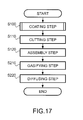
Here, reference to FIG. 6 is made again. At step S110 (cutting step), the glass plate 2 on which the coating layers have been formed is cut.
Here, reference to FIG. 6 is made again. At step S120 (assembly step), the cut glass plates are assembled. At this time, they are assembled with at least one surface open for holding an ampule at the next step. For example, all members except the glass plate 11 forming the upper surface of the gas cell array 10 are assembled. In the assembly, the glass plates are joined by welding or bonding using an adhesive agent, for example.
At step S130 (ampule holding step), an ampule is held in the dummy cell 130 within the gas cell array 10. The ampule is put from the open surface.
Here, reference to FIG. 6 is made again. At step S140 (sealing step), the gas cell array 10 is sealed. In this example, in addition to an alkali metal gas, an inert gas (buffer gas) such as a rare gas is enclosed within the gas cell according to need. In this case, the sealing of the gas cell array 10 is performed in an inert gas atmosphere. Specifically, in the inert gas atmosphere, the member of the open surface (for example, the glass plate 11 forming the upper surface) is joined.
At step S150 (ampule breaking step), the ampule 200 is broken. Specifically, a laser beam focused on the ampule 200 is applied to the ampule 200, and a hole is pierced in the ampule.
At step S160 (gasifying step), the alkali metal solid within the ampule 200 is gasified. Specifically, the alkali metal solid is heated by heating the gas cell array 10, and gasified.
At step S170 (diffusing step), the alkali metal gas is diffused. Specifically, the gas is held at a certain temperature (a temperature higher than the room temperature is desirable) in a fixed period, and thereby, the alkali metal gas is diffused.
Note that, in the case where the coating layer is formed by the OTS molecules only, the heat resistance is better, but the number of collisions until the spin polarization disappears is about 2,100 at most and lower than that of paraffin. It is conceivable that this is because shielding in the alkyl groups forming OTS is insufficient and exposure of the polar parts starting from the glass surface and the oxygen atoms of the OTS molecules, paramagnetic impurities such as oxygen, carbon dioxide, or the like increases the adsorption energy of the alkali metal atoms. On the other hand, in the embodiment, the OTS layer is formed on the inner walls of the gas cell and the exposure of the polar groups on the inner wall surfaces of the gas cell may be reduced, and the paraffin layer is formed on the OTS layer and the anti-relaxation characteristics of the inner walls of the gas cell may be improved.
The invention is not limited to the above described embodiment, but various modifications can be made. As below, several modified examples will be explained. Two or more of the following modified examples may be combined for use.
In the above described embodiment, OTS has been used as the first molecules having functional groups to be chemically bonded to the polar groups of the inner walls of the gas cells and non-polar groups, however, the carbon number of its alkyl group is not limited to that. The first molecules may be another silane coupling agent such as dichlorodimethylsilane, dichlorooctadecylsiloxane, or methyltrichlorosilane. Further, the first molecules may be molecules that express the so-called anchor effect, not limited to the silane coupling agent.
Furthermore, in the above described embodiment, the paraffin has been used as the non-polar second molecule, however, the second molecules are not limited to paraffin. For example, another hydrocarbon may be used. The second molecules may be any non-polar second molecules.
In addition, in the above described embodiment, the gas cell (gas cell array) formed using the material such as quartz glass or borosilicate glass has been used, however, the material forming the gas cell is not limited to the quartz glass or borosilicate glass. Any gas cell including inner walls formed using a compound having polar groups or a material containing the compound may be used.
As shown in FIG. 16 , in this example, the gas cell 110 and the gas cell 120 have a through hole 112 and a through hole 122 connected to the dummy cell 160. Though not shown in the sectional view, the gas cell 140 and the gas cell 150 also have through holes connected to the dummy cell 160.
The specific details of the ampule breaking step are not limited to those explained in the embodiment. The ampule 200 may have a part in which two materials having different coefficients of thermal expansion are bonded. In this case, at the ampule breaking step, the ampule 200 (the entire gas cell array holding it) is heated in place of laser beam application. At heating, heat to a degree of breaking the ampule 200 due to the difference in coefficient of thermal expansion is applied.
Further, the breaking of the ampule is not limited to that by the laser beam application. The ampule may be broken by applying dynamic impact or vibration so that the ampule 200 may collide with the inner wall of an ampule container 53. In another example, heat for generating thermal stress may be applied to the ampule 200, and the ampule 200 may be broken by the thermal stress.
The manufacturing method of the gas cell array is not limited to that exemplified in FIG. 6 . Another step may be added to the steps shown in FIG. 6 . Or, the order of the steps may be changed or part of the steps may be omitted. For example, the order of the coating step and the cutting step may be exchanged. In this case, the glass plate is first cut and the coating layer is formed after the cutting. In another example, after the formation of the coating layer, a step of peeling a part of the layer may be introduced. In this case, of the glass plates, the coating layer in the joint part to the other glass plate is peeled. Or, of the glass plates, the coating layer on the surface exposed to the outside may be peeled.
In another example, the sealing step may be performed under vacuum. In this case, the gas cell has no inert gas, but only the alkali metal gas inside.
The shape of the dummy cell is not limited to that explained in the embodiment. The dummy cell may have a recess part for holding fragment of the ampule. The recess part is provided in a corner part, for example, for minimizing the effect on the measurement of the magnetic field. The recess part may be formed on the glass plate before assembly, or formed by joining a part to be the recess part to the glass plate with a hole. Further, an adhesive material may be accumulated in the recess part so that the fragment of the ampule may not move at transfer (carriage).
The shape of the gas cell is not limited to that explained in the embodiment. In the embodiment, the example in which the shape of the gas cell is rectangular parallelepiped has been explained, however, the shape of the gas cell may be another polyhedron than the rectangular parallelepiped, or a shape having a curved surface in a part such as a cylinder. For example, the gas cell may have a reservoir (metal reservoir) for accumulating the alkali metal solid when the temperature becomes lower to the temperature or less at which the alkali metal atoms solidify. Note that it is only necessary that the alkali metal is gasified at least at measurement and not necessary that the alkali metal is constantly in the gas state.
In yet another example, the manufacturing method of the modified example may be used not for the gas cell array, but for a single gas cell. In this case, no dummy cell is formed, but the alkali metal solid may be directly (without using an ampule) held within the gas cell. Further, the gas cell may be manufactured by glass shaping, or formed by glass processing. In the case of the single gas cell, as is the case of the above described embodiment, the inner walls are coated with the first molecules such as OTS molecules, then further coated with the second molecules such as paraffin thereon, and thereby, the exposure of the polar groups of the inner walls of the gas cell is reduced and the improvement of the anti-relaxation performance of the spin polarization is expected.
In place of the formation of the through holes by laser beam application, a step of generating thermal stress by light application and tearing the ampule 200 by the thermal stress may be used. According to the method, compared to the case where the through holes are formed by light application, degassing (gas emitted from the glass or the like during the step) may be reduced and the sensor characteristics may be improved. In this case, laser having a pulse width of sub-nanoseconds or less may be used. Further, for facilitation of the tearing of the ampule 200, apart of stress concentration (for example, scratch) may be formed in the ampule 200.
In the above described embodiment and modified examples, the example in which, when the alkali metal atoms are introduced into the gas cells, they are introduced in the solid state has been explained. However, the state when the alkali metal atoms are introduced in the gas cells is not limited to solid. The alkali metal atoms may be introduced into the gas cells in any state of solid, liquid, or gas. Further, a capsule may be used in place of the ampule.
The application of the gas cell is not limited to the magnetic sensor. For example, the gas cell may be used for an atomic oscillator.
The entire disclosure of Japanese Patent Application No. 2012-047700, filed Mar. 5, 2012, is expressly incorporated by reference herein.
Claims (7)
1. A magnetic measurement system comprising:
an array of gas cells that are each formed of a material having light transmissivity and being filled with alkali metal gas, the array of gas cells being entirely peripherally surrounded by a dummy gas cell that communicates with each of the gas cells of the array through a hole formed in each gas cell of the array, the through holes of adjacent gas cells of the array being co-axially aligned; and
a light radiation unit, the light radiation unit configured to irradiate a light onto each of the gas cells of the array,
wherein each gas cell of the array includes inner glass wall surfaces being coated with a first coating layer and a second coating layer;
the first coating layer includes methyltrichlorosilane that is chemically bonded to the inner glass wall surfaces of each gas cell of the array; and
the second coating layer includes non-polar second molecules, which are physically adsorbed to the silane.
2. The magnetic measurement system according to claim 1 , wherein the chemical bond between the inner glass wall and the silane is an Si—O—Si bond.
3. The magnetic measurement system according to claim 1 , wherein the second molecules are hydrocarbon.
4. The magnetic measurement system according to claim 3 , wherein the hydrocarbon is paraffin.
5. A method of fabricating a magnetic measuring system including an array of gas cells and a light radiation unit, the array of gas cells being entirely peripherally surrounded by a dummy gas cell that communicates with each of the gas cells of the array through a hole formed in each gas cell of the array, the through holes of adjacent gas cells of the array being co-axially aligned, and the array of gas cells being formed using a material having light transmissivity and being filled with alkali metal atoms, and inner walls of each of the gas cells of the array being formed of a glass material, the method comprising:
providing the magnetic measuring system; and
providing the array of gas cells, the step of providing the array of gas cells including:
forming a first coating layer by coating the inner glass walls with methyltrichlorosilane material that chemically bonds to silicon atoms in the inner glass walls, and non-polar groups; and
physically adsorbing a second coating layer having non-polar second molecules to the silane.
6. The magnetic measurement system according to claim 1 , wherein the dummy gas cell is unitary with the array of gas cells.
7. The method of claim 5 , wherein the dummy gas cell is unitary with the array of gas cells.
Applications Claiming Priority (2)
| Application Number | Priority Date | Filing Date | Title |
|---|---|---|---|
| JP2012047700A JP5994293B2 (en) | 2012-03-05 | 2012-03-05 | Magnetometer, gas cell, and gas cell manufacturing method |
| JP2012-047700 | 2012-03-05 |
Publications (2)
| Publication Number | Publication Date |
|---|---|
| US20130230673A1 US20130230673A1 (en) | 2013-09-05 |
| US9521958B2 true US9521958B2 (en) | 2016-12-20 |
Family
ID=49042989
Family Applications (1)
| Application Number | Title | Priority Date | Filing Date |
|---|---|---|---|
| US13/780,273 Active 2033-03-02 US9521958B2 (en) | 2012-03-05 | 2013-02-28 | Gas cell and coating method of gas cell |
Country Status (2)
| Country | Link |
|---|---|
| US (1) | US9521958B2 (en) |
| JP (1) | JP5994293B2 (en) |
Cited By (10)
| Publication number | Priority date | Publication date | Assignee | Title |
|---|---|---|---|---|
| US20150369427A1 (en) * | 2014-06-23 | 2015-12-24 | Seiko Epson Corporation | Gas Cell |
| US20160109538A1 (en) * | 2014-10-21 | 2016-04-21 | Seiko Epson Corporation | Magnetism measurement apparatus, gas cell, method for manufacturing magnetism measurement apparatus, and method for manufacturing gas cell |
| US20170023654A1 (en) * | 2015-07-21 | 2017-01-26 | Canon Kabushiki Kaisha | Optically pumped magnetometer and magnetic sensing method |
| US20170023653A1 (en) * | 2015-07-21 | 2017-01-26 | Canon Kabushiki Kaisha | Optically pumped magnetometer and magnetic sensing method |
| US11273283B2 (en) | 2017-12-31 | 2022-03-15 | Neuroenhancement Lab, LLC | Method and apparatus for neuroenhancement to enhance emotional response |
| US11364361B2 (en) | 2018-04-20 | 2022-06-21 | Neuroenhancement Lab, LLC | System and method for inducing sleep by transplanting mental states |
| US11452839B2 (en) | 2018-09-14 | 2022-09-27 | Neuroenhancement Lab, LLC | System and method of improving sleep |
| US11717686B2 (en) | 2017-12-04 | 2023-08-08 | Neuroenhancement Lab, LLC | Method and apparatus for neuroenhancement to facilitate learning and performance |
| US11723579B2 (en) | 2017-09-19 | 2023-08-15 | Neuroenhancement Lab, LLC | Method and apparatus for neuroenhancement |
| US11786694B2 (en) | 2019-05-24 | 2023-10-17 | NeuroLight, Inc. | Device, method, and app for facilitating sleep |
Families Citing this family (10)
| Publication number | Priority date | Publication date | Assignee | Title |
|---|---|---|---|---|
| JP2016029362A (en) * | 2014-07-24 | 2016-03-03 | セイコーエプソン株式会社 | Gas cell and magnetic measuring device |
| US10145909B2 (en) * | 2014-11-17 | 2018-12-04 | Seiko Epson Corporation | Magnetism measuring device, gas cell, manufacturing method of magnetism measuring device, and manufacturing method of gas cell |
| JP2017147402A (en) * | 2016-02-19 | 2017-08-24 | セイコーエプソン株式会社 | Atomic cell and method of manufacturing the same, quantum interference device, atomic oscillator, electronic apparatus and moving body |
| US10396809B2 (en) * | 2016-02-19 | 2019-08-27 | Seiko Epson Corporation | Atomic cell, atomic cell manufacturing method, quantum interference device, atomic oscillator, electronic apparatus, and vehicle |
| JP2018004430A (en) * | 2016-07-01 | 2018-01-11 | セイコーエプソン株式会社 | Method for manufacturing gas cell, method for manufacturing magnetic measuring device, and gas cell |
| JP2018137397A (en) * | 2017-02-23 | 2018-08-30 | セイコーエプソン株式会社 | Quantum interference device, atomic oscillator, electronic apparatus, and mobile |
| CN108614224B (en) * | 2018-04-03 | 2020-09-18 | 北京航天控制仪器研究所 | Automatic calibration system and method for air chamber working temperature of CPT magnetometer |
| JP7238698B2 (en) | 2019-08-28 | 2023-03-14 | セイコーエプソン株式会社 | quantum interference device |
| WO2023079767A1 (en) * | 2021-11-02 | 2023-05-11 | 株式会社多摩川ホールディングス | Gas cell and method for manufacturing same |
| CN116609710B (en) * | 2023-03-29 | 2024-03-29 | 中国科学技术大学 | Manufacturing method of atomic air chamber containing multiple reflecting cavities based on cavity mirror side bonding |
Citations (17)
| Publication number | Priority date | Publication date | Assignee | Title |
|---|---|---|---|---|
| US3863144A (en) * | 1973-10-17 | 1975-01-28 | Singer Co | High sensitivity gradient magnetometer |
| JPH06271840A (en) | 1993-03-19 | 1994-09-27 | Matsushita Electric Ind Co Ltd | Siloxane-based surface treating agent, its production and use thereof |
| US5435839A (en) | 1992-12-24 | 1995-07-25 | Matsushita Electric Industrial Co., Ltd. | Finishing agents and method of manufacturing the same |
| US5545255A (en) | 1992-05-27 | 1996-08-13 | Matsushita Electric Industrial Co., Ltd. | Finishing agent and method of using the same |
| US6086795A (en) * | 1997-10-29 | 2000-07-11 | Ciba Specialty Chemicals Corp. | Adhesive compositions |
| US6383677B1 (en) * | 1999-10-07 | 2002-05-07 | Allen Engineering Company, Inc. | Fuel cell current collector |
| US6577802B1 (en) * | 2000-07-13 | 2003-06-10 | Corning Incorporated | Application of silane-enhanced adhesion promoters for optical fibers and fiber ribbons |
| US20030157391A1 (en) * | 2002-02-05 | 2003-08-21 | Gencell Corporation | Silane coated metallic fuel cell components and methods of manufacture |
| US7038450B2 (en) * | 2002-10-16 | 2006-05-02 | Trustees Of Princeton University | High sensitivity atomic magnetometer and methods for using same |
| US20070076776A1 (en) * | 2005-07-22 | 2007-04-05 | Honeywell International Inc. | Technique for optically pumping alkali-metal atoms using cpt resonances |
| US20070120563A1 (en) * | 2005-11-28 | 2007-05-31 | Ryuuzou Kawabata | Magnetic field measurement system and optical pumping magnetometer |
| US20070167723A1 (en) * | 2005-12-29 | 2007-07-19 | Intel Corporation | Optical magnetometer array and method for making and using the same |
| US20080069949A1 (en) * | 2006-09-15 | 2008-03-20 | Degussa Gmbh | Silane-functional, chlorine-free composition |
| US7531594B2 (en) * | 2002-08-12 | 2009-05-12 | Exxonmobil Chemical Patents Inc. | Articles from plasticized polyolefin compositions |
| JP2009236599A (en) | 2008-03-26 | 2009-10-15 | Canon Inc | Optical pumping magnetometer |
| US7662480B2 (en) * | 2006-03-14 | 2010-02-16 | Lanxess, Inc. | Butyl ionomer having improved surface adhesion |
| JP2010085134A (en) | 2008-09-30 | 2010-04-15 | Hitachi High-Technologies Corp | Magnetic field measuring device |
-
2012
- 2012-03-05 JP JP2012047700A patent/JP5994293B2/en active Active
-
2013
- 2013-02-28 US US13/780,273 patent/US9521958B2/en active Active
Patent Citations (19)
| Publication number | Priority date | Publication date | Assignee | Title |
|---|---|---|---|---|
| US3863144A (en) * | 1973-10-17 | 1975-01-28 | Singer Co | High sensitivity gradient magnetometer |
| US5545255A (en) | 1992-05-27 | 1996-08-13 | Matsushita Electric Industrial Co., Ltd. | Finishing agent and method of using the same |
| US5876806A (en) | 1992-05-27 | 1999-03-02 | Matsushita Electric Industrial Co., Ltd. | Finishing agent and method of using the same |
| US5435839A (en) | 1992-12-24 | 1995-07-25 | Matsushita Electric Industrial Co., Ltd. | Finishing agents and method of manufacturing the same |
| US5645633A (en) | 1992-12-24 | 1997-07-08 | Matsushita Electric Industrial Co., Ltd. | Finishing agents and method of manufacturing the same |
| JPH06271840A (en) | 1993-03-19 | 1994-09-27 | Matsushita Electric Ind Co Ltd | Siloxane-based surface treating agent, its production and use thereof |
| US6086795A (en) * | 1997-10-29 | 2000-07-11 | Ciba Specialty Chemicals Corp. | Adhesive compositions |
| US6383677B1 (en) * | 1999-10-07 | 2002-05-07 | Allen Engineering Company, Inc. | Fuel cell current collector |
| US6577802B1 (en) * | 2000-07-13 | 2003-06-10 | Corning Incorporated | Application of silane-enhanced adhesion promoters for optical fibers and fiber ribbons |
| US20030157391A1 (en) * | 2002-02-05 | 2003-08-21 | Gencell Corporation | Silane coated metallic fuel cell components and methods of manufacture |
| US7531594B2 (en) * | 2002-08-12 | 2009-05-12 | Exxonmobil Chemical Patents Inc. | Articles from plasticized polyolefin compositions |
| US7038450B2 (en) * | 2002-10-16 | 2006-05-02 | Trustees Of Princeton University | High sensitivity atomic magnetometer and methods for using same |
| US20070076776A1 (en) * | 2005-07-22 | 2007-04-05 | Honeywell International Inc. | Technique for optically pumping alkali-metal atoms using cpt resonances |
| US20070120563A1 (en) * | 2005-11-28 | 2007-05-31 | Ryuuzou Kawabata | Magnetic field measurement system and optical pumping magnetometer |
| US20070167723A1 (en) * | 2005-12-29 | 2007-07-19 | Intel Corporation | Optical magnetometer array and method for making and using the same |
| US7662480B2 (en) * | 2006-03-14 | 2010-02-16 | Lanxess, Inc. | Butyl ionomer having improved surface adhesion |
| US20080069949A1 (en) * | 2006-09-15 | 2008-03-20 | Degussa Gmbh | Silane-functional, chlorine-free composition |
| JP2009236599A (en) | 2008-03-26 | 2009-10-15 | Canon Inc | Optical pumping magnetometer |
| JP2010085134A (en) | 2008-09-30 | 2010-04-15 | Hitachi High-Technologies Corp | Magnetic field measuring device |
Non-Patent Citations (1)
| Title |
|---|
| M. A. Bouchiat and J. Brossel, "Relaxation of Optically Rb Atoms on Paraffin-Coated Walls", Physical Review, vol. 147, No. 1, pp. 41-54 (1965). |
Cited By (13)
| Publication number | Priority date | Publication date | Assignee | Title |
|---|---|---|---|---|
| US20150369427A1 (en) * | 2014-06-23 | 2015-12-24 | Seiko Epson Corporation | Gas Cell |
| US20160109538A1 (en) * | 2014-10-21 | 2016-04-21 | Seiko Epson Corporation | Magnetism measurement apparatus, gas cell, method for manufacturing magnetism measurement apparatus, and method for manufacturing gas cell |
| US10107876B2 (en) * | 2014-10-21 | 2018-10-23 | Seiko Epson Corporation | Magnetism measurement apparatus, gas cell, method for manufacturing magnetism measurement apparatus, and method for manufacturing gas cell |
| US20170023654A1 (en) * | 2015-07-21 | 2017-01-26 | Canon Kabushiki Kaisha | Optically pumped magnetometer and magnetic sensing method |
| US20170023653A1 (en) * | 2015-07-21 | 2017-01-26 | Canon Kabushiki Kaisha | Optically pumped magnetometer and magnetic sensing method |
| US11723579B2 (en) | 2017-09-19 | 2023-08-15 | Neuroenhancement Lab, LLC | Method and apparatus for neuroenhancement |
| US11717686B2 (en) | 2017-12-04 | 2023-08-08 | Neuroenhancement Lab, LLC | Method and apparatus for neuroenhancement to facilitate learning and performance |
| US11318277B2 (en) | 2017-12-31 | 2022-05-03 | Neuroenhancement Lab, LLC | Method and apparatus for neuroenhancement to enhance emotional response |
| US11478603B2 (en) | 2017-12-31 | 2022-10-25 | Neuroenhancement Lab, LLC | Method and apparatus for neuroenhancement to enhance emotional response |
| US11273283B2 (en) | 2017-12-31 | 2022-03-15 | Neuroenhancement Lab, LLC | Method and apparatus for neuroenhancement to enhance emotional response |
| US11364361B2 (en) | 2018-04-20 | 2022-06-21 | Neuroenhancement Lab, LLC | System and method for inducing sleep by transplanting mental states |
| US11452839B2 (en) | 2018-09-14 | 2022-09-27 | Neuroenhancement Lab, LLC | System and method of improving sleep |
| US11786694B2 (en) | 2019-05-24 | 2023-10-17 | NeuroLight, Inc. | Device, method, and app for facilitating sleep |
Also Published As
| Publication number | Publication date |
|---|---|
| JP2013181941A (en) | 2013-09-12 |
| US20130230673A1 (en) | 2013-09-05 |
| JP5994293B2 (en) | 2016-09-21 |
Similar Documents
| Publication | Publication Date | Title |
|---|---|---|
| US9521958B2 (en) | Gas cell and coating method of gas cell | |
| US9684041B2 (en) | Production method of gas cell, and gas cell | |
| Lin et al. | Electron transport across plasmonic molecular nanogaps interrogated with surface-enhanced Raman scattering | |
| Drobek et al. | MOF-based membrane encapsulated ZnO nanowires for enhanced gas sensor selectivity | |
| EP2884262B1 (en) | Surface-enhanced raman scattering unit | |
| ES2526773T3 (en) | Graphene Polymer Compound | |
| CN110044494A (en) | A kind of heat-sensitive eye array and its manufacturing method | |
| Stavila et al. | Thin film growth of nbo MOFs and their integration with electroacoustic devices | |
| JP5994408B2 (en) | Package sealing method and gas cell manufacturing method | |
| JP2011017683A5 (en) | ||
| US8904850B1 (en) | Materials, methods and devices to detect and quantify water vapor concentrations in an atmosphere | |
| US20150369427A1 (en) | Gas Cell | |
| Gumilar et al. | Performance enhancement strategies for surface plasmon resonance sensors in direct glucose detection using pristine and modified UiO-66: effects of morphology, immobilization technique, and signal amplification | |
| Kim et al. | Coffee ring effect free TiO2 nanotube array for quantitative laser desorption/ionization mass spectrometry | |
| CN107121156B (en) | The encapsulation type light miniflow microcavity biochemical sensor of radial higher order mode can be retained | |
| US20160001942A1 (en) | Lid, gas cell, sealing method for gas cell, manufacturing method for lid, and lid array substrate | |
| Liu et al. | Induced SERS activity in Ag@ SiO2/Ag core‐shell nanosphere arrays with tunable interior insulator | |
| Kohut et al. | One-step fabrication of fiber optic SERS sensors via spark ablation | |
| JP6464593B2 (en) | Gas cell manufacturing method | |
| JP2005134370A (en) | Dual para-xylylene layers for x-ray detector | |
| JP6519627B2 (en) | Gas cell | |
| US20200340923A1 (en) | A sensor comprising a nanoporous material and method for detecting an analyte using the sensor | |
| KR102531589B1 (en) | Organic-inorganic hybrid receptor, biosensor probe and biosensor | |
| CN108642471A (en) | A kind of preparation process and its hydrogen gas sensor of palladium nano-particles film | |
| Sutrová et al. | Excitation wavelength dependence of combined surface-and graphene-enhanced Raman scattering experienced by free-base phthalocyanine localized on single-layer graphene-covered Ag nanoparticle arrays |
Legal Events
| Date | Code | Title | Description |
|---|---|---|---|
| AS | Assignment |
Owner name: SEIKO EPSON CORPORATION, JAPAN Free format text: ASSIGNMENT OF ASSIGNORS INTEREST;ASSIGNORS:NAGASAKA, KIMIO;YOKOKAWA, SHINOBU;REEL/FRAME:029895/0376 Effective date: 20130115 |
|
| STCF | Information on status: patent grant |
Free format text: PATENTED CASE |
|
| MAFP | Maintenance fee payment |
Free format text: PAYMENT OF MAINTENANCE FEE, 4TH YEAR, LARGE ENTITY (ORIGINAL EVENT CODE: M1551); ENTITY STATUS OF PATENT OWNER: LARGE ENTITY Year of fee payment: 4 |