US9545253B2 - Surgical instrument with contained dual helix actuator assembly - Google Patents
Surgical instrument with contained dual helix actuator assembly Download PDFInfo
- Publication number
- US9545253B2 US9545253B2 US13/622,735 US201213622735A US9545253B2 US 9545253 B2 US9545253 B2 US 9545253B2 US 201213622735 A US201213622735 A US 201213622735A US 9545253 B2 US9545253 B2 US 9545253B2
- Authority
- US
- United States
- Prior art keywords
- articulation
- end effector
- rotation
- shaft
- lead screw
- Prior art date
- Legal status (The legal status is an assumption and is not a legal conclusion. Google has not performed a legal analysis and makes no representation as to the accuracy of the status listed.)
- Active, expires
Links
Images


Classifications
-
- A—HUMAN NECESSITIES
- A61—MEDICAL OR VETERINARY SCIENCE; HYGIENE
- A61B—DIAGNOSIS; SURGERY; IDENTIFICATION
- A61B17/00—Surgical instruments, devices or methods, e.g. tourniquets
- A61B17/068—Surgical staplers, e.g. containing multiple staples or clamps
- A61B17/072—Surgical staplers, e.g. containing multiple staples or clamps for applying a row of staples in a single action, e.g. the staples being applied simultaneously
- A61B17/07207—Surgical staplers, e.g. containing multiple staples or clamps for applying a row of staples in a single action, e.g. the staples being applied simultaneously the staples being applied sequentially
-
- A—HUMAN NECESSITIES
- A61—MEDICAL OR VETERINARY SCIENCE; HYGIENE
- A61B—DIAGNOSIS; SURGERY; IDENTIFICATION
- A61B18/00—Surgical instruments, devices or methods for transferring non-mechanical forms of energy to or from the body
- A61B18/04—Surgical instruments, devices or methods for transferring non-mechanical forms of energy to or from the body by heating
- A61B18/12—Surgical instruments, devices or methods for transferring non-mechanical forms of energy to or from the body by heating by passing a current through the tissue to be heated, e.g. high-frequency current
- A61B18/14—Probes or electrodes therefor
- A61B18/1442—Probes having pivoting end effectors, e.g. forceps
- A61B18/1445—Probes having pivoting end effectors, e.g. forceps at the distal end of a shaft, e.g. forceps or scissors at the end of a rigid rod
- A61B18/1447—Probes having pivoting end effectors, e.g. forceps at the distal end of a shaft, e.g. forceps or scissors at the end of a rigid rod wherein sliding surfaces cause opening/closing of the end effectors
-
- A—HUMAN NECESSITIES
- A61—MEDICAL OR VETERINARY SCIENCE; HYGIENE
- A61B—DIAGNOSIS; SURGERY; IDENTIFICATION
- A61B17/00—Surgical instruments, devices or methods, e.g. tourniquets
- A61B17/00234—Surgical instruments, devices or methods, e.g. tourniquets for minimally invasive surgery
- A61B2017/00292—Surgical instruments, devices or methods, e.g. tourniquets for minimally invasive surgery mounted on or guided by flexible, e.g. catheter-like, means
- A61B2017/003—Steerable
-
- A—HUMAN NECESSITIES
- A61—MEDICAL OR VETERINARY SCIENCE; HYGIENE
- A61B—DIAGNOSIS; SURGERY; IDENTIFICATION
- A61B17/00—Surgical instruments, devices or methods, e.g. tourniquets
- A61B2017/00367—Details of actuation of instruments, e.g. relations between pushing buttons, or the like, and activation of the tool, working tip, or the like
- A61B2017/00371—Multiple actuation, e.g. pushing of two buttons, or two working tips becoming operational
- A61B2017/0038—Simultaneous actuation of two tools by pushing one button or the like
-
- A—HUMAN NECESSITIES
- A61—MEDICAL OR VETERINARY SCIENCE; HYGIENE
- A61B—DIAGNOSIS; SURGERY; IDENTIFICATION
- A61B17/00—Surgical instruments, devices or methods, e.g. tourniquets
- A61B2017/0042—Surgical instruments, devices or methods, e.g. tourniquets with special provisions for gripping
- A61B2017/00455—Orientation indicators, e.g. recess on the handle
-
- A—HUMAN NECESSITIES
- A61—MEDICAL OR VETERINARY SCIENCE; HYGIENE
- A61B—DIAGNOSIS; SURGERY; IDENTIFICATION
- A61B17/00—Surgical instruments, devices or methods, e.g. tourniquets
- A61B17/28—Surgical forceps
- A61B17/29—Forceps for use in minimally invasive surgery
- A61B2017/2901—Details of shaft
- A61B2017/2908—Multiple segments connected by articulations
-
- A—HUMAN NECESSITIES
- A61—MEDICAL OR VETERINARY SCIENCE; HYGIENE
- A61B—DIAGNOSIS; SURGERY; IDENTIFICATION
- A61B17/00—Surgical instruments, devices or methods, e.g. tourniquets
- A61B17/28—Surgical forceps
- A61B17/29—Forceps for use in minimally invasive surgery
- A61B2017/2926—Details of heads or jaws
- A61B2017/2927—Details of heads or jaws the angular position of the head being adjustable with respect to the shaft
- A61B2017/2929—Details of heads or jaws the angular position of the head being adjustable with respect to the shaft with a head rotatable about the longitudinal axis of the shaft
-
- A—HUMAN NECESSITIES
- A61—MEDICAL OR VETERINARY SCIENCE; HYGIENE
- A61B—DIAGNOSIS; SURGERY; IDENTIFICATION
- A61B17/00—Surgical instruments, devices or methods, e.g. tourniquets
- A61B17/28—Surgical forceps
- A61B17/29—Forceps for use in minimally invasive surgery
- A61B2017/2946—Locking means
-
- A—HUMAN NECESSITIES
- A61—MEDICAL OR VETERINARY SCIENCE; HYGIENE
- A61B—DIAGNOSIS; SURGERY; IDENTIFICATION
- A61B18/00—Surgical instruments, devices or methods for transferring non-mechanical forms of energy to or from the body
- A61B2018/00636—Sensing and controlling the application of energy
- A61B2018/00642—Sensing and controlling the application of energy with feedback, i.e. closed loop control
-
- A—HUMAN NECESSITIES
- A61—MEDICAL OR VETERINARY SCIENCE; HYGIENE
- A61B—DIAGNOSIS; SURGERY; IDENTIFICATION
- A61B18/00—Surgical instruments, devices or methods for transferring non-mechanical forms of energy to or from the body
- A61B2018/00636—Sensing and controlling the application of energy
- A61B2018/00696—Controlled or regulated parameters
- A61B2018/00702—Power or energy
-
- A—HUMAN NECESSITIES
- A61—MEDICAL OR VETERINARY SCIENCE; HYGIENE
- A61B—DIAGNOSIS; SURGERY; IDENTIFICATION
- A61B18/00—Surgical instruments, devices or methods for transferring non-mechanical forms of energy to or from the body
- A61B2018/00636—Sensing and controlling the application of energy
- A61B2018/00773—Sensed parameters
- A61B2018/00791—Temperature
- A61B2018/00815—Temperature measured by a thermistor
-
- A—HUMAN NECESSITIES
- A61—MEDICAL OR VETERINARY SCIENCE; HYGIENE
- A61B—DIAGNOSIS; SURGERY; IDENTIFICATION
- A61B18/00—Surgical instruments, devices or methods for transferring non-mechanical forms of energy to or from the body
- A61B2018/00636—Sensing and controlling the application of energy
- A61B2018/00773—Sensed parameters
- A61B2018/00875—Resistance or impedance
-
- A—HUMAN NECESSITIES
- A61—MEDICAL OR VETERINARY SCIENCE; HYGIENE
- A61B—DIAGNOSIS; SURGERY; IDENTIFICATION
- A61B18/00—Surgical instruments, devices or methods for transferring non-mechanical forms of energy to or from the body
- A61B2018/00636—Sensing and controlling the application of energy
- A61B2018/00773—Sensed parameters
- A61B2018/00892—Voltage
-
- A—HUMAN NECESSITIES
- A61—MEDICAL OR VETERINARY SCIENCE; HYGIENE
- A61B—DIAGNOSIS; SURGERY; IDENTIFICATION
- A61B18/00—Surgical instruments, devices or methods for transferring non-mechanical forms of energy to or from the body
- A61B18/04—Surgical instruments, devices or methods for transferring non-mechanical forms of energy to or from the body by heating
- A61B18/12—Surgical instruments, devices or methods for transferring non-mechanical forms of energy to or from the body by heating by passing a current through the tissue to be heated, e.g. high-frequency current
- A61B18/14—Probes or electrodes therefor
- A61B18/1442—Probes having pivoting end effectors, e.g. forceps
- A61B2018/1452—Probes having pivoting end effectors, e.g. forceps including means for cutting
- A61B2018/1455—Probes having pivoting end effectors, e.g. forceps including means for cutting having a moving blade for cutting tissue grasped by the jaws
Definitions
- a variety of surgical instruments include a tissue cutting element and one or more elements that transmit RF energy to tissue (e.g., to coagulate or seal the tissue).
- tissue e.g., to coagulate or seal the tissue
- ENSEAL® Tissue Sealing Device by Ethicon Endo-Surgery, Inc., of Cincinnati, Ohio.
- Further examples of such devices and related concepts are disclosed in U.S. Pat. No. 6,500,176 entitled “Electrosurgical Systems and Techniques for Sealing Tissue,” issued Dec. 31, 2002, the disclosure of which is incorporated by reference herein; U.S. Pat. No. 7,112,201 entitled “Electrosurgical Instrument and Method of Use,” issued Sep. 26, 2006, the disclosure of which is incorporated by reference herein; U.S. Pat. No.
- a variety of surgical instruments include a shaft having an articulation section, providing enhanced positioning capabilities for an end effector that is located distal to the articulation section of the shaft.
- Examples of such devices include various models of the ENDOPATH® endocutters by Ethicon Endo-Surgery, Inc., of Cincinnati, Ohio.
- Further examples of such devices and related concepts are disclosed in U.S. Pat. No. 7,380,696, entitled “Articulating Surgical Stapling Instrument Incorporating a Two-Piece E-Beam Firing Mechanism,” issued Jun. 3, 2008, the disclosure of which is incorporated by reference herein; U.S. Pat. No. 7,404,508, entitled “Surgical Stapling and Cutting Device,” issued Jul.
- FIG. 1 depicts a side elevational view of an exemplary electrosurgical medical device
- FIG. 3 depicts another perspective view of the end effector of the device of FIG. 1 , in an open configuration
- FIG. 4 depicts a cross-sectional end view of the end effector of FIG. 2 , in a closed configuration and with the blade in a distal position, taken along line 4 - 4 of FIG. 3 ;
- FIG. 5 depicts a perspective view of another exemplary electrosurgical medical device, with an articulation control knob
- FIG. 8 depicts a perspective view of a support member of the shaft assembly of the device of FIG. 5 ;
- FIG. 9 depicts a partial perspective view of articulation control components of the device of FIG. 5 , along one side of the support member;
- FIG. 13 depicts a side elevational view of the handle assembly of the device of FIG. 5 , with a housing half removed;
- FIG. 14 depicts a side elevational view of articulation control components of the handle assembly of FIG. 13 , with half of an articulation control knob body removed;
- FIG. 16 depicts a side cross-sectional view of the articulation control components of FIG. 15 , taken along line 16 - 16 of FIG. 15 ;
- FIG. 17A depicts a partial cross-sectional view of articulation control components and the articulation section of the shaft of the device of FIG. 5 , with the articulation section in a substantially straight configuration;
- FIG. 17B depicts a partial cross-sectional view of the components of FIG. 17A , with the articulation section in a first stage of articulation;
- FIG. 17C depicts a partial cross-sectional view of the components of FIG. 17A , with the articulation section in a second stage of articulation;
- FIG. 18 depicts a side elevational view of the handle assembly of an exemplary alternative electrosurgical medical device with an articulation control knob
- FIG. 19 depicts a side elevational view of articulation control components of the handle assembly of FIG. 18 , with half of an articulation control knob body removed;
- FIG. 20 depicts a side cross-sectional view of articulation control components of the handle assembly of FIG. 18 ;
- FIG. 21 depicts a perspective view of articulation control components of the handle assembly of FIG. 18 ;
- FIG. 22 depicts a top cross-sectional view of the articulation control components of FIG. 21 , taken along line 22 - 22 of FIG. 21 ;
- FIG. 23 depicts an exploded perspective view of some of the articulation control components of the handle assembly of FIG. 18 ;
- FIG. 24 depicts another exploded perspective view of some of the articulation control components of the handle assembly of FIG. 18 ;
- FIG. 25 depicts a cross-sectional end view of a detent feature of the articulation control components of the handle assembly of FIG. 18 , taken along line 25 - 25 of FIG. 18 ;
- FIG. 26 depicts a perspective view of an exemplary alternative rivet member that may be used in the articulation control components of a handle assembly
- FIG. 27 depicts a top cross-sectional view of articulation control components including the rivet member of FIG. 26 ;
- FIG. 28 depicts a partial side view distal portion of an exemplary alternative handle assembly, with a housing half and other components removed to reveal an exemplary friction ring;
- FIG. 29 depicts a partial perspective view of exemplary articulation braking features that may be used in the articulation control components of a handle assembly
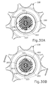
- FIG. 30A depicts an end view of the articulation braking features of FIG. 29 , with the knob at a home position where the articulation section of the shaft is substantially straight;
- FIG. 30B depicts an end view of the articulation braking features of FIG. 29 , with the knob at a rotated position where the articulation section of the shaft is substantially articulated.
- FIGS. 1-4 show an exemplary electrosurgical instrument ( 10 ) that is constructed and operable in accordance with at least some of the teachings of U.S. Pat. No. 6,500,176; U.S. Pat. No. 7,112,201; U.S. Pat. No. 7,125,409; U.S. Pat. No. 7,169,146; U.S. Pat. No. 7,186,253; U.S. Pat. No. 7,189,233; U.S. Pat. No. 7,220,951; U.S. Pat. No. 7,309,849; U.S. Pat. No. 7,311,709; U.S. Pat. No. 7,354,440; U.S. Pat. No. 7,381,209; U.S. Pub.
- electrosurgical instrument ( 10 ) is operable to cut tissue and seal or weld tissue (e.g., a blood vessel, etc.) substantially simultaneously.
- electrosurgical instrument ( 10 ) operates similar to an endocutter type of stapler, except that electrosurgical instrument ( 10 ) provides tissue welding through application of bipolar RF energy instead of providing lines of staples to join tissue.
- electrosurgical instrument ( 10 ) may have various structural and functional similarities with the ENSEAL® Tissue Sealing Device by Ethicon Endo-Surgery, Inc., of Cincinnati, Ohio. Furthermore, electrosurgical instrument ( 10 ) may have various structural and functional similarities with the devices taught in any of the other references that are cited and incorporated by reference herein. To the extent that there is some degree of overlap between the teachings of the references cited herein, the ENSEAL® Tissue Sealing Device by Ethicon Endo-Surgery, Inc., of Cincinnati, Ohio, and the following teachings relating to electrosurgical instrument ( 10 ), there is no intent for any of the description herein to be presumed as admitted prior art. Several teachings below will in fact go beyond the scope of the teachings of the references cited herein and the ENSEAL® Tissue Sealing Device by Ethicon Endo-Surgery, Inc., of Cincinnati, Ohio.
- Electrosurgical instrument ( 10 ) of the present example includes a handpiece ( 20 ), a shaft ( 30 ) extending distally from handpiece ( 20 ), and an end effector ( 40 ) disposed at a distal end of shaft ( 30 ).
- Handpiece ( 20 ) of the present example includes a pistol grip ( 22 ), a pivoting trigger ( 24 ), an activation button ( 26 ), and an articulation control ( 28 ).
- Trigger ( 24 ) is pivotable toward and away from pistol grip ( 22 ) to selectively actuate end effector ( 40 ) as will be described in greater detail below.
- Activation button ( 26 ) is operable to selectively activate RF circuitry that is in communication with end effector ( 40 ), as will also be described in greater detail below.
- activation button ( 26 ) also serves as a mechanical lockout against trigger ( 24 ), such that trigger ( 24 ) cannot be fully actuated unless button ( 26 ) is being pressed simultaneously. Examples of how such a lockout may be provided are disclosed in one or more of the references cited herein. It should be understood that pistol grip ( 22 ), trigger ( 24 ), and button ( 26 ) may be modified, substituted, supplemented, etc. in any suitable way, and that the descriptions of such components herein are merely illustrative. Articulation control ( 28 ) of the present example is operable to selectively control articulation section ( 36 ) of shaft ( 30 ), which will be described in greater detail below. Various examples of forms that articulation control ( 28 ) may take will also be described in greater detail below, while further examples will be apparent to those of ordinary skill in the art in view of the teachings herein.
- Shaft ( 30 ) of the present example includes an outer sheath ( 32 ) and an articulation section ( 36 ).
- Articulation section ( 36 ) is operable to selectively position end effector ( 40 ) at various angles relative to the longitudinal axis defined by sheath ( 32 ).
- end effector ( 40 ) is operable to selectively position end effector ( 40 ) at various angles relative to the longitudinal axis defined by sheath ( 32 ).
- articulation section ( 36 ) and other components of shaft ( 30 ) may take will be described in greater detail below, while further examples will be apparent to those of ordinary skill in the art in view of the teachings herein. For instance, it should be understood that various components that are operable to actuate articulation section ( 36 ) may extend through the interior of sheath ( 32 ).
- shaft ( 30 ) is also rotatable about the longitudinal axis defined by sheath ( 32 ), relative to handpiece ( 20 ), via a knob ( 34 ). Such rotation may provide rotation of end effector ( 40 ) and shaft ( 30 ) unitarily.
- knob ( 34 ) is operable to rotate end effector ( 40 ) without rotating any portion of shaft ( 30 ) that is proximal of articulation section ( 36 ).
- electrosurgical instrument ( 10 ) may include one rotation control that provides rotatability of shaft ( 30 ) and end effector ( 40 ) as a single unit; and another rotation control that provides rotatability of end effector ( 40 ) without rotating any portion of shaft ( 30 ) that is proximal of articulation section ( 36 ).
- Other suitable rotation schemes will be apparent to those of ordinary skill in the art in view of the teachings herein.
- rotatable features may simply be omitted if desired.
- End effector ( 40 ) of the present example comprises a first jaw ( 42 ) and a second jaw ( 44 ).
- second jaw ( 44 ) is substantially fixed relative to shaft ( 30 ); while first jaw ( 42 ) pivots relative to shaft ( 30 ), toward and away from second jaw ( 42 ).
- actuators such as rods or cables, etc., may extend through sheath ( 32 ) and be joined with first jaw ( 42 ) at a pivotal coupling ( 43 ), such that longitudinal movement of the actuator rods/cables/etc. through shaft ( 30 ) provides pivoting of first jaw ( 42 ) relative to shaft ( 30 ) and relative to second jaw ( 44 ).
- jaws ( 42 , 44 ) may instead have any other suitable kind of movement and may be actuated in any other suitable fashion.
- jaws ( 42 , 44 ) may be actuated and thus closed by longitudinal translation of a firing beam ( 60 ), such that actuator rods/cables/etc. may simply be eliminated in some versions.
- first jaw ( 42 ) defines a longitudinally extending elongate slot ( 46 ); while second jaw ( 44 ) also defines a longitudinally extending elongate slot ( 48 ).
- first electrode surface ( 50 ) presents a first electrode surface ( 50 ); while the underside of second jaw ( 44 ) presents a second electrode surface ( 52 ).
- Electrode surfaces ( 50 , 52 ) are in communication with an electrical source ( 80 ) via one or more conductors (not shown) that extend along the length of shaft ( 30 ).
- Electrical source ( 80 ) is operable to deliver RF energy to first electrode surface ( 50 ) at a first polarity and to second electrode surface ( 52 ) at a second (opposite) polarity, such that RF current flows between electrode surfaces ( 50 , 52 ) and thereby through tissue captured between jaws ( 42 , 44 ).
- firing beam ( 60 ) serves as an electrical conductor that cooperates with electrode surfaces ( 50 , 52 ) (e.g., as a ground return) for delivery of bipolar RF energy captured between jaws ( 42 , 44 ).
- Electrical source ( 80 ) may be external to electrosurgical instrument ( 10 ) or may be integral with electrosurgical instrument ( 10 ) (e.g., in handpiece ( 20 ), etc.), as described in one or more references cited herein or otherwise.
- a controller ( 82 ) regulates delivery of power from electrical source ( 80 ) to electrode surfaces ( 50 , 52 ). Controller ( 82 ) may also be external to electrosurgical instrument ( 10 ) or may be integral with electrosurgical instrument ( 10 ) (e.g., in handpiece ( 20 ), etc.), as described in one or more references cited herein or otherwise. It should also be understood that electrode surfaces ( 50 , 52 ) may be provided in a variety of alternative locations, configurations, and relationships.
- first jaw ( 42 ) includes a longitudinally extending recess ( 58 ) adjacent to slot ( 46 ); while the upper side of second jaw ( 44 ) includes a longitudinally extending recess ( 58 ) adjacent to slot ( 48 ).
- FIG. 2 shows the upper side of first jaw ( 42 ) including a plurality of teeth serrations ( 46 ). It should be understood that the lower side of second jaw ( 44 ) may include complementary serrations that nest with serrations ( 46 ), to enhance gripping of tissue captured between jaws ( 42 , 44 ) without necessarily tearing the tissue.
- serrations ( 46 ) in first jaw ( 42 ) as mainly recesses; with serrations ( 48 ) in second jaw ( 44 ) as mainly protrusions.
- serrations ( 46 , 48 ) may take any other suitable form or may be simply omitted altogether.
- serrations ( 46 , 48 ) may be formed of an electrically non-conductive, or insulative, material, such as plastic, glass, and/or ceramic, for example, and may include a treatment such as polytetrafluoroethylene, a lubricant, or some other treatment to substantially prevent tissue from getting stuck to jaws ( 42 , 44 ).
- shaft ( 30 ) and end effector ( 40 ) are sized and configured to fit through trocars having various inner diameters, such that electrosurgical instrument ( 10 ) is usable in minimally invasive surgery, though of course electrosurgical instrument ( 10 ) could also be used in open procedures if desired.
- shaft ( 30 ) and end effector ( 40 ) may present an outer diameter of approximately 5 mm.
- shaft ( 30 ) and end effector ( 40 ) may present any other suitable outer diameter (e.g., between approximately 2 mm and approximately 20 mm, etc.).
- either jaw ( 42 , 44 ) or both of jaws ( 42 , 44 ) may include at least one port, passageway, conduit, and/or other feature that is operable to draw steam, smoke, and/or other gases/vapors/etc. from the surgical site.
- a feature may be in communication with a source of suction, such as an external source or a source within handpiece ( 20 ), etc.
- end effector ( 40 ) may include one or more tissue cooling features (not shown) that reduce the degree or extent of thermal spread caused by end effector ( 40 ) on adjacent tissue when electrode surfaces ( 50 , 52 ) are activated.
- tissue cooling features not shown
- end effector ( 40 ) includes one or more sensors (not shown) that are configured to sense a variety of parameters at end effector ( 40 ), including but not limited to temperature of adjacent tissue, electrical resistance or impedance of adjacent tissue, voltage across adjacent tissue, forces exerted on jaws ( 42 , 44 ) by adjacent tissue, etc.
- end effector ( 40 ) may include one or more positive temperature coefficient (PTC) thermistor bodies ( 54 , 56 ) (e.g., PTC polymer, etc.), located adjacent to electrodes ( 50 , 52 ) and/or elsewhere.
- PTC positive temperature coefficient
- Controller ( 82 ) may process such data in a variety of ways.
- controller ( 82 ) may modulate or otherwise change the RF energy being delivered to electrode surfaces ( 50 , 52 ), based at least in part on data acquired from one or more sensors at end effector ( 40 ).
- controller ( 82 ) may alert the user to one or more conditions via an audio and/or visual feedback device (e.g., speaker, lights, display screen, etc.), based at least in part on data acquired from one or more sensors at end effector ( 40 ).
- an audio and/or visual feedback device e.g., speaker, lights, display screen, etc.
- some kinds of sensors need not necessarily be in communication with controller ( 82 ), and may simply provide a purely localized effect at end effector ( 40 ).
- a PTC thermistor bodies ( 54 , 56 ) at end effector ( 40 ) may automatically reduce the energy delivery at electrode surfaces ( 50 , 52 ) as the temperature of the tissue and/or end effector ( 40 ) increases, thereby reducing the likelihood of overheating.
- a PTC thermistor element is in series with power source ( 80 ) and electrode surface ( 50 , 52 ); and the PTC thermistor provides an increased impedance (reducing flow of current) in response to temperatures exceeding a threshold.
- electrode surfaces ( 50 , 52 ) may be used as sensors (e.g., to sense tissue impedance, etc.).
- electrosurgical instrument ( 10 ) Various kinds of sensors that may be incorporated into electrosurgical instrument ( 10 ) will be apparent to those of ordinary skill in the art in view of the teachings herein. Similarly various things that can be done with data from sensors, by controller ( 82 ) or otherwise, will be apparent to those of ordinary skill in the art in view of the teachings herein. Other suitable variations for end effector ( 40 ) will also be apparent to those of ordinary skill in the art in view of the teachings herein.
- electrosurgical instrument ( 10 ) of the present example includes a firing beam ( 60 ) that is longitudinally movable along part of the length of end effector ( 40 ).
- Firing beam ( 60 ) is coaxially positioned within shaft ( 30 ), extends along the length of shaft ( 30 ), and translates longitudinally within shaft ( 30 ) (including articulation section ( 36 ) in the present example), though it should be understood that firing beam ( 60 ) and shaft ( 30 ) may have any other suitable relationship.
- Firing beam ( 60 ) includes a sharp distal blade ( 64 ), an upper flange ( 62 ), and a lower flange ( 66 ). As best seen in FIG.
- distal blade ( 64 ) extends through slots ( 46 , 48 ) of jaws ( 42 , 44 ), with upper flange ( 62 ) being located above jaw ( 44 ) in recess ( 59 ) and lower flange ( 66 ) being located below jaw ( 42 ) in recess ( 58 ).
- the configuration of distal blade ( 64 ) and flanges ( 62 , 66 ) provides an “I-beam” type of cross section at the distal end of firing beam ( 60 ).
- flanges ( 62 , 66 ) extend longitudinally only along a small portion of the length of firing beam ( 60 ) in the present example, it should be understood that flanges ( 62 , 66 ) may extend longitudinally along any suitable length of firing beam ( 60 ).
- flanges ( 62 , 66 ) are positioned along the exterior of jaws ( 42 , 44 ), flanges ( 62 , 66 ) may alternatively be disposed in corresponding slots formed within jaws ( 42 , 44 ).
- each jaw ( 42 , 44 ) may define a “T”-shaped slot, with parts of distal blade ( 64 ) being disposed in one vertical portion of each “T”-shaped slot and with flanges ( 62 , 66 ) being disposed in the horizontal portions of the “T”-shaped slots.
- flanges 62 , 66
- Distal blade ( 64 ) is substantially sharp, such that distal blade ( 64 ) will readily sever tissue that is captured between jaws ( 42 , 44 ). Distal blade ( 64 ) is also electrically grounded in the present example, providing a return path for RF energy as described elsewhere herein. In some other versions, distal blade ( 64 ) serves as an active electrode. In addition or in the alternative, distal blade ( 64 ) may be selectively energized with ultrasonic energy (e.g., harmonic vibrations at approximately 55.5 kHz, etc.).
- ultrasonic energy e.g., harmonic vibrations at approximately 55.5 kHz, etc.
- the “I-beam” type of configuration of firing beam ( 60 ) provides closure of jaws ( 42 , 44 ) as firing beam ( 60 ) is advanced distally.
- flange ( 62 ) urges jaw ( 44 ) pivotally toward jaw ( 42 ) as firing beam ( 60 ) is advanced from a proximal position ( FIGS. 1-3 ) to a distal position ( FIG. 4 ), by bearing against recess ( 59 ) formed in jaw ( 44 ).
- This closing effect on jaws ( 42 , 44 ) by firing beam ( 60 ) may occur before distal blade ( 64 ) reaches tissue captured between jaws ( 42 , 44 ).
- firing beam ( 60 ) may reduce the force required to squeeze grip ( 24 ) to actuate firing beam ( 60 ) through a full firing stroke.
- firing beam ( 60 ) may have already overcome an initial resistance required to substantially close jaws ( 42 , 44 ) on tissue before encountering resistance from severing the tissue captured between jaws ( 42 , 44 ).
- any other suitable staging may be provided.
- flange ( 62 ) is configured to cam against a ramp feature at the proximal end of jaw ( 44 ) to open jaw ( 42 ) when firing beam ( 60 ) is retracted to a proximal position and to hold jaw ( 42 ) open when firing beam ( 60 ) remains at the proximal position.
- This camming capability may facilitate use of end effector ( 40 ) to separate layers of tissue, to perform blunt dissections, etc., by forcing jaws ( 42 , 44 ) apart from a closed position.
- jaws ( 42 , 44 ) are resiliently biased to an open position by a spring or other type of resilient feature.
- jaws ( 42 , 44 ) close or open as firing beam ( 60 ) is translated in the present example
- other versions may provide independent movement of jaws ( 42 , 44 ) and firing beam ( 60 ).
- one or more cables, rods, beams, or other features may extend through shaft ( 30 ) to selectively actuate jaws ( 42 , 44 ) independently of firing beam ( 60 ).
- Such jaw ( 42 , 44 ) actuation features may be separately controlled by a dedicated feature of handpiece ( 20 ).
- jaw actuation features may be controlled by trigger ( 24 ) in addition to having trigger ( 24 ) control firing beam ( 60 ).
- firing beam ( 60 ) may be resiliently biased to a proximal position, such that firing beam ( 60 ) retracts proximally when a user relaxes their grip on trigger ( 24 ).
- end effector ( 40 ) is inserted into a patient via a trocar.
- Articulation section ( 36 ) is substantially straight when end effector ( 40 ) and part of shaft ( 30 ) are inserted through the trocar.
- Articulation control ( 28 ) may then be manipulated to pivot or flex articulation section ( 36 ) of shaft ( 30 ) in order to position end effector ( 40 ) at a desired position and orientation relative to an anatomical structure within the patient.
- Two layers of tissue of the anatomical structure are then captured between jaws ( 42 , 44 ) by squeezing trigger ( 24 ) toward pistol grip ( 22 ).
- Such layers of tissue may be part of the same natural lumen defining anatomical structure (e.g., blood vessel, portion of gastrointestinal tract, portion of reproductive system, etc.) in a patient.
- one tissue layer may comprise the top portion of a blood vessel while the other tissue layer may comprise the bottom portion of the blood vessel, along the same region of length of the blood vessel (e.g., such that the fluid path through the blood vessel before use of electrosurgical instrument ( 10 ) is perpendicular to the longitudinal axis defined by end effector ( 40 ), etc.).
- the lengths of jaws ( 42 , 44 ) may be oriented perpendicular to (or at least generally transverse to) the length of the blood vessel.
- flanges ( 62 , 66 ) cammingly act to pivot jaw ( 44 ) toward jaw ( 44 ) when firing beam ( 60 ) is actuated distally by squeezing trigger ( 24 ) toward pistol grip ( 22 ).
- firing beam ( 60 ) continues to advance distally by the user squeezing trigger ( 24 ) toward pistol grip ( 22 ).
- distal blade ( 64 ) simultaneously severs the clamped tissue layers, resulting in separated upper layer portions being apposed with respective separated lower layer portions. In some versions, this results in a blood vessel being cut in a direction that is generally transverse to the length of the blood vessel. It should be understood that the presence of flanges ( 62 , 66 ) immediately above and below jaws ( 42 , 44 ), respectively, may help keep jaws ( 42 , 44 ) in a closed and tightly clamping position.
- flanges ( 62 , 66 ) may help maintain a significantly compressive force between jaws ( 42 , 44 ).
- electrode surfaces ( 50 , 52 ) are activated with bipolar RF energy by the user depressing activation button ( 26 ).
- electrodes ( 50 , 52 ) are selectively coupled with power source ( 80 ) (e.g., by the user depressing button ( 26 ), etc.) such that electrode surfaces ( 50 , 52 ) of jaws ( 42 , 44 ) are activated with a common first polarity while firing beam ( 60 ) is activated at a second polarity that is opposite to the first polarity.
- a bipolar RF current flows between firing beam ( 60 ) and electrode surfaces ( 50 , 52 ) of jaws ( 42 , 44 ), through the compressed regions of severed tissue layer portions.
- electrode surface ( 50 ) has one polarity while electrode surface ( 52 ) and firing beam ( 60 ) both have the other polarity.
- bipolar RF energy delivered by power source ( 80 ) ultimately thermally welds the tissue layer portions on one side of firing beam ( 60 ) together and the tissue layer portions on the other side of firing beam ( 60 ) together.
- the heat generated by activated electrode surfaces ( 50 , 52 ) can denature the collagen within the tissue layer portions and, in cooperation with clamping pressure provided by jaws ( 42 , 44 ), the denatured collagen can form a seal within the tissue layer portions.
- the severed ends of the natural lumen defining anatomical structure are hemostatically sealed shut, such that the severed ends will not leak bodily fluids.
- electrode surfaces ( 50 , 52 ) may be activated with bipolar RF energy before firing beam ( 60 ) even begins to translate distally and thus before the tissue is even severed. For instance, such timing may be provided in versions where button ( 26 ) serves as a mechanical lockout relative to trigger ( 24 ) in addition to serving as a switch between power source ( 80 ) and electrode surfaces ( 50 , 52 ).
- electrosurgical instrument ( 10 ) While several of the teachings below are described as variations to electrosurgical instrument ( 10 ), it should be understood that various teachings below may also be incorporated into various other types of devices. By way of example only, in addition to being readily incorporated into electrosurgical instrument ( 10 ), various teachings below may be readily incorporated into the devices taught in any of the references cited herein, other types of electrosurgical devices, surgical staplers, surgical clip appliers, and tissue graspers, among various other devices. Other suitable devices into which the following teachings may be incorporated will be apparent to those of ordinary skill in the art in view of the teachings herein.
- Articulation section ( 36 ) of shaft ( 30 ) may take a variety of forms.
- articulation section ( 36 ) may be configured in accordance with one or more teachings of U.S. Pub. No. 2012/0078247, entitled “Articulation Joint Features for Articulating Surgical Device,” published Mar. 29, 2012, now U.S. Pat. No. 9,402,682, issued Aug. 2, 2016, the disclosure of which is incorporated by reference herein.
- articulation section ( 36 ) may be configured in accordance with one or more teachings of U.S. Pub. No. 2012/0078248, entitled “Articulation Joint Features for Articulating Surgical Device,” published Mar. 29, 2012, now U.S. Pat. No.
- articulation section may be configured in accordance with the teachings of at least one other of the references cited herein.
- Various other suitable forms that articulation section ( 36 ) may take will be apparent to those of ordinary skill in the art in view of the teachings herein.
- some versions of handpiece ( 20 ) include an articulation control ( 28 ), which is operable to control articulation section ( 36 ) of shaft ( 30 ) to thereby selectively position end effector ( 40 ) at various angles relative to the longitudinal axis defined by sheath ( 32 ).
- articulation control ( 28 ) and other components of handpiece ( 20 ) may take will be described in greater detail below, while further examples will be apparent to those of ordinary skill in the art in view of the teachings herein.
- some merely illustrative alternative examples of articulation control ( 28 ) are disclosed in U.S. Pub. No. 2012/0078243, entitled “Control Features for Articulating Surgical Device,” published Mar. 29, 2012, the disclosure of which is incorporated by reference herein; and in U.S. Pub. No. 2012/0078244, entitled “Control Features for Articulating Surgical Device,” published Mar. 29, 2012, the disclosure of which is incorporated by reference herein.
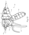
- FIG. 5 depicts an exemplary electrosurgical instrument ( 100 ) that includes a handpiece ( 120 ), a shaft ( 130 ) extending distally from handpiece ( 120 ), and an end effector ( 140 ) disposed at a distal end of shaft ( 130 ).
- Handpiece ( 120 ) of the present example includes a pistol grip ( 122 ), a pivoting trigger ( 124 ), an activation button ( 126 ), and a rotary articulation knob ( 128 ).
- Trigger ( 124 ) is pivotable toward and away from pistol grip ( 122 ) to selectively actuate end effector ( 140 ) as described above and as described in one or more of the references cited herein.
- Activation button ( 126 ) is operable to selectively activate RF circuitry that is in communication with end effector ( 140 ), as also described above and as described in one or more reference cited herein.
- activation button ( 126 ) also serves as a mechanical lockout against trigger ( 124 ), such that trigger ( 124 ) cannot be fully actuated unless button ( 126 ) is being pressed simultaneously. Examples of how such a lockout may be provided are disclosed in one or more of the references cited herein. It should be understood that pistol grip ( 122 ), trigger ( 124 ), and button ( 126 ) may be modified, substituted, supplemented, etc. in any suitable way, and that the descriptions of such components herein are merely illustrative. Articulation knob ( 128 ) of the present example is operable to selectively control articulation section ( 136 ) of shaft ( 130 ), as will be described in greater detail below.
- Shaft ( 130 ) of the present example includes an outer sheath ( 132 ), an articulation section ( 136 ) at the distal end of sheath ( 132 ), and a cutting member driver tube ( 138 ) that is slidably and coaxially disposed within sheath ( 132 ).
- Cutting member driver tube ( 138 ) is secured to a driver block ( 139 ), which is further secured to a cutting member ( 146 ) of end effector ( 140 ).
- Cutting member driver tube ( 138 ) is movable longitudinally to drive driver block ( 139 ) longitudinally, to thereby move cutting member ( 146 ) longitudinally.
- Cutting member ( 146 ) is essentially equivalent to firing beam ( 60 ) described above.
- the proximal portion ( 148 ) of end effector ( 140 ) includes an insert (not shown) that defines a channel containing the part of cutting member ( 146 ) that extends through proximal portion ( 148 ). This channel is configured to permit cutting member ( 146 ) to readily translate relative to the insert, while also preventing cutting member ( 146 ) from buckling within the insert when cutting member ( 146 ) encounters a load during distal advancement of cutting member ( 146 ).
- driver tube ( 138 ) is advanced distally by squeezing trigger ( 124 ) toward pistol grip ( 122 ); while driver tube ( 138 ) is retracted proximally by releasing trigger ( 124 ) and/or by actively moving trigger ( 124 ) away from pistol grip ( 122 ).
- a yoke ( 125 ) couples trigger ( 124 ) with driver tube ( 138 ).
- cutting member ( 146 ) may be moved in any other suitable fashion.
- Articulation section ( 136 ) of the present example is operable to selectively position end effector ( 140 ) at various angles relative to the longitudinal axis defined by sheath ( 132 ).
- end effector ( 140 ) may be configured in accordance with end effector ( 40 ) described above, in accordance with the teachings of various references cited herein, and/or in any other suitable way as will be apparent to those of ordinary skill in the art in view of the teachings herein.
- shaft ( 130 ) is also rotatable about the longitudinal axis defined by sheath ( 132 ), relative to handpiece ( 120 ), via a knob ( 134 ). Such rotation may provide rotation of end effector ( 140 ) and shaft ( 130 ) unitarily.
- knob ( 134 ) is operable to rotate end effector ( 140 ) without rotating any portion of shaft ( 130 ) that is proximal of articulation section ( 136 ).
- electrosurgical instrument ( 100 ) may include one rotation control that provides rotatability of shaft ( 130 ) and end effector ( 140 ) as a single unit; and another rotation control that provides rotatability of end effector ( 140 ) without rotating any portion of shaft ( 130 ) that is proximal of section ( 136 ).
- Other suitable rotation schemes will be apparent to those of ordinary skill in the art in view of the teachings herein.
- rotatable features may simply be omitted if desired.
- FIGS. 6-12 show various components of shaft ( 130 ) that provide control for articulation of articulation section ( 136 ).
- these components include a separator ( 150 ), a first articulation band ( 160 ) with an associated drive member ( 162 ), and a second articulation band ( 170 ) with an associated drive member ( 172 ).
- separator ( 150 ) includes an upper lumen ( 151 ), a middle lumen ( 152 ), and a lower lumen ( 153 ).
- Separator ( 150 ) also includes side recesses ( 154 ), a distal projection ( 156 ), and a gap ( 158 ).
- Separator ( 150 ) is disposed within cutting member driver tube ( 138 ) and maintains a fixed longitudinal position during operation of instrument ( 100 ). Thus, separator ( 150 ) and outer sheath ( 132 ) remain stationary relative to each other and relative to handpiece ( 120 ); while cutting member driver tube ( 138 ) reciprocates relative to separator ( 150 ), outer sheath ( 132 ), and handpiece ( 120 ).
- Distal projection ( 156 ) is configured to permit translation of driver block ( 139 ) substantially free from interference by distal projection ( 156 ) or by any other portion of separator ( 150 ).
- separator ( 150 ) is formed as two pieces arranged in an end-to-end configuration, with a distal projection from the proximal piece helping to define gap ( 158 ).
- separator ( 150 ) may alternatively be formed as a single piece or any other suitable number of pieces.
- gap ( 158 ) may be formed as a cutout from a single piece of material.
- a wire ( 900 ) extends through separator ( 150 ) to provide electrical communication to end effector ( 140 ).
- wire ( 900 ) extends through middle lumen ( 152 ) from the proximal end of separator ( 150 ) until wire ( 900 ) reaches gap ( 158 ).
- wire ( 900 ) transitions down to lower lumen ( 153 ), and extends through lower lumen ( 153 ) until reaching the distal end of separator ( 150 ).
- Wire ( 900 ) then extends across articulation section ( 136 ) to end effector ( 140 ).
- Wire ( 900 ) is thus operable to communicate power from a power source to end effector ( 140 ) in accordance with the teachings herein and in accordance with the teachings of various references cited herein.
- Distal projection ( 156 ) protects wire ( 900 ) from driver block ( 139 ), such that driver block ( 139 ) is unable to contact wire ( 900 ) regardless of the longitudinal position of driver block ( 139 ) along distal projection ( 156 ).
- First articulation band ( 160 ) is slidably disposed in one side recess ( 154 ) of separator ( 150 ) while second articulation band ( 170 ) is slidably disposed in the other side recess ( 154 ) of separator ( 150 ).
- side recesses ( 154 ) include longitudinally extending grooves ( 155 ) that are configured to reduce the contact surface area with articulation bands ( 160 , 170 ), thereby reducing friction between separator ( 150 ) and articulation bands ( 160 , 170 ).
- Separator ( 150 ) may also be formed of a low friction material and/or include a surface treatment to reduce friction.
- Articulation bands ( 160 , 170 ) both extend longitudinally along the entire length of shaft ( 130 ), including through articulation section ( 136 ). As shown in FIG. 7 , the distal end ( 166 ) of first articulation band ( 160 ) is secured to one side of the proximal portion ( 148 ) of end effector ( 140 ) at an anchor point. The distal end ( 176 ) of second articulation band ( 170 ) is secured to the other side of proximal portion ( 148 ) of end effector ( 140 ) at an anchor point.
- rotary articulation knob ( 128 ) is operable to selectively advance one articulation band ( 160 , 170 ) distally while simultaneously retracting the other articulation band ( 160 , 170 ) proximally, and vice-versa. It should be understood that this opposing translation will cause articulation section ( 136 ) to bend, thereby articulating end effector ( 140 ). In particular, end effector ( 140 ) will deflect toward whichever articulation band ( 160 , 170 ) is being retracted proximally; and away from whichever articulation band ( 160 , 170 ) is being advanced distally.
- drive member ( 162 ) is unitarily secured to articulation band ( 160 ) and includes a notch ( 164 ) extending laterally inwardly.
- drive member ( 172 ) is unitarily secured to articulation band ( 170 ) and includes a notch ( 174 ) extending laterally inwardly.
- drive members ( 162 , 164 ) are spaced and configured such that notches ( 164 , 174 ) are at different longitudinal positions along the length of separator ( 150 ).
- the proximal portion of cutting member driver tube ( 138 ) includes longitudinally extending slots ( 137 ).
- Drive members ( 162 , 172 ) are slidably disposed in slots ( 137 ) and notches ( 164 , 174 ) are radially positioned outside the outer circumference of cutting member driver tube ( 138 ).
- Slots ( 137 ) are configured to enable free translation of cutting member driver tube ( 138 ) relative to drive members ( 162 , 172 ), to thus enable free actuation of cutting member ( 164 ) regardless of the articulation state of articulation section ( 136 ).
- slots ( 137 ) are configured to enable free translation of drive members ( 162 , 172 ) relative to cutting member driver tube ( 138 ), to thus enable free articulation of articulation section ( 136 ) regardless of the longitudinal position of cutting member ( 164 ).
- rotary articulation knob ( 128 ) is coaxially positioned about the proximal portion of driver tube ( 138 ) and encompasses drive members ( 162 , 172 ). Articulation knob ( 128 ) is oriented perpendicular to the longitudinal axis defined by shaft ( 130 ) and is rotatable about the longitudinal axis defined by shaft ( 130 ).
- articulation knob ( 128 ) As will be described in greater detail below, such rotation of articulation knob ( 128 ) will cause opposing translation of drive members ( 162 , 172 ), with the directions of such opposing translations depending on the direction in which articulation knob ( 128 ) is rotated, such that rotation of articulation knob ( 128 ) will articulate end effector ( 140 ).
- articulation knob ( 128 ) includes a first internal threading ( 180 ) and a second internal threading ( 182 ). Threadings ( 181 , 182 ) have opposing pitch angles or orientations in this example.
- first lead screw ( 183 ) and a second lead screw ( 184 ) are slidably disposed along a pair of pins ( 123 ), which are secured to housing ( 121 ).
- lead screws ( 183 , 184 ) are operable to translate within housing ( 121 ) but are prevented from rotating within housing ( 121 ).
- First lead screw ( 183 ) includes exterior threading ( 185 ) that is engaged with threading ( 181 ) of articulation knob ( 128 ); while second lead screw ( 184 ) includes exterior threading ( 186 ) that is engaged with threading ( 182 ) of articulation knob ( 128 ).
- the pitch angle of threading ( 185 ) complements the pitch angle of threading ( 181 ); while the pitch angle of threading ( 186 ) complements the pitch angle of threading ( 182 ). It should therefore be understood that, due to the opposing pitch angles, rotation of knob ( 128 ) in a first direction will drive lead screw ( 183 ) distally while simultaneously driving lead screw ( 184 ) proximally; and rotation of knob in a second direction will drive lead screw ( 183 ) proximally while simultaneously driving lead screw ( 184 ) distally.
- the angles of threading ( 181 , 182 , 185 , 186 ) are also configured such that articulation section ( 136 ) will be effectively locked in any given articulated position, such that transverse loads on end effector ( 140 ) will generally not bend articulation section ( 136 ), due to friction between threading ( 181 , 182 , 185 , 186 ).
- articulation section ( 136 ) will only change its configuration when knob ( 128 ) is rotated. While the angles of threading may substantially prevent bending of articulation section ( 136 ) in response to transverse loads on end effector ( 140 ), the angles may still provide ready rotation of articulation knob ( 128 ) to translate lead screws ( 183 , 184 ).
- angles of threading may be approximately +/ ⁇ 2 degrees or approximately +/ ⁇ 3 degrees. Other suitable angles will be apparent to those of ordinary skill in the art in view of the teachings herein. It should also be understood that threading ( 181 , 182 , 185 , 186 ) may have a square or rectangular cross-section or any other suitable configuration.
- first tensioner gear ( 191 ) is threadably engaged with first lead screw ( 183 ); while a second tensioner gear ( 192 ) is threadably engaged with second lead screw ( 184 ).
- first tensioner gear ( 191 ) relative to first lead screw ( 183 ) may be adjusted by rotating first tensioner gear ( 191 ) relative to first lead screw ( 183 ); while the longitudinal position of second tensioner gear ( 192 ) relative to second lead screw ( 184 ) may be adjusted by rotating second tensioner gear ( 192 ) relative to second lead screw ( 184 ).
- first tensioner gear ( 191 ) will translate unitarily with first lead screw ( 183 ); while second tensioner gear ( 192 ) will translate unitarily with second lead screw ( 184 ).
- First tensioner gear ( 191 ) is also engaged with a washer ( 193 ), which is further engaged with notch ( 174 ) of drive member ( 172 ).
- the engagement between washer ( 193 ) and drive member ( 172 ) is such that washer ( 193 ) and drive member ( 172 ) will translate together.
- washer ( 193 ) is secured to tensioner gear ( 191 ) in such a manner that tensioner gear ( 191 ) both pulls washer ( 193 ) distally and pushes washer ( 193 ) proximally.
- first lead screw ( 183 ) is operable to both push articulation band ( 170 ) distally and pull articulation band ( 170 ) proximally, depending on which direction knob ( 128 ) is rotated.
- tensioner gear ( 191 ) merely abuts washer ( 193 ), such that tensioner gear ( 191 ) is operable to push washer ( 193 ) proximally but cannot pull washer ( 193 ) distally.
- first lead screw ( 183 ) is operable to pull articulation band ( 170 ) proximally but cannot actively push articulation band ( 170 ) distally.
- first lead screw ( 183 ) may simply pull tensioner gear ( 191 ) distally to enable articulation band ( 170 ), drive member ( 172 ), and washer ( 193 ) to be driven distally in response to proximal retraction of articulation band ( 160 ) as communicated through articulation section ( 136 ).
- drive member ( 172 ) and/or washer ( 193 ) may be rotatable relative to tensioner gear ( 191 ), which may permit rotation of shaft ( 130 ) by knob ( 134 ).
- tensioner gear ( 191 ) may be used to take out any tolerance gaps between drive member ( 172 ) and lead screw ( 183 ).
- second tensioner gear ( 192 ) is engaged with a washer ( 194 ), which is further engaged with notch ( 164 ) of drive member ( 162 ).
- the engagement between washer ( 194 ) and drive member ( 162 ) is such that washer ( 194 ) and drive member ( 162 ) will translate together.
- washer ( 194 ) is secured to tensioner gear ( 192 ) in such a manner that tensioner gear ( 192 ) both pulls washer ( 194 ) distally and pushes washer ( 194 ) proximally.
- second lead screw ( 184 ) is operable to both push articulation band ( 160 ) distally and pull articulation band ( 160 ) proximally, depending on which direction knob ( 128 ) is rotated.
- tensioner gear ( 192 ) merely abuts washer ( 194 ), such that tensioner gear ( 192 ) is operable to push washer ( 194 ) proximally but cannot pull washer ( 194 ) distally.
- second lead screw ( 184 ) is operable to pull articulation band ( 160 ) proximally but cannot actively push articulation band ( 160 ) distally.
- second lead screw ( 184 ) may simply pull tensioner gear ( 192 ) distally to enable articulation band ( 160 ), drive member ( 162 ), and washer ( 194 ) to be driven distally in response to proximal retraction of articulation band ( 170 ) as communicated through articulation section ( 136 ).
- drive member ( 162 ) and/or washer ( 194 ) may be rotatable relative to tensioner gear ( 192 ), which may permit rotation of shaft ( 130 ) by knob ( 134 ).
- tensioner gear ( 192 ) may be used to take out any tolerance gaps between drive member ( 162 ) and lead screw ( 184 ).
- FIGS. 17A-17C show several of the above described components interacting to bend articulation section ( 136 ) to articulate end effector ( 140 ).
- articulation ( 136 ) is in a substantially straight configuration.
- knob ( 128 ) is rotated, which causes lead screw ( 183 ) to translate proximally and lead screw ( 184 ) to advance distally.
- This proximal translation of lead screw ( 183 ) pulls articulation band ( 170 ) proximally, which causes articulation section ( 136 ) to start bending as shown in FIG. 17B .
- This bending of articulation section ( 136 ) pulls articulation band ( 160 ) distally.
- knob ( 128 ) includes a visual indicator that is associated with articulation section ( 136 ) being in a substantially straight configuration.
- a visual indicator may align with a corresponding visual indicator on housing ( 121 ) of handpiece ( 120 ).
- the user may observe such indicators to confirm whether articulation section ( 136 ) has in fact reached a substantially straight configuration.
- this may be done right before instrument ( 100 ) is withdrawn from a trocar to reduce the likelihood of articulation section ( 136 ) snagging on a distal edge of the trocar.
- such indicators are merely optional.
- manufacturing inconsistencies may result in articulation bands ( 160 , 170 ) having slightly different lengths.
- Such inconsistencies may result in lost motion or slop in the operation of the articulation features of instrument ( 100 ).
- tensioner gears ( 191 , 192 ) may be rotated relative to lead screws ( 183 , 184 ) to adjust the longitudinal position of drive members ( 162 , 172 ) relative to lead screws ( 183 , 184 ). For instance, if there is insufficient tension in articulation band ( 170 ), tensioner gear ( 191 ) may be rotated to drive washer ( 193 ) and drive member ( 172 ) proximally until articulation band ( 170 ) reaches a sufficient degree of tension.
- tensioner gear ( 192 ) may be rotated to drive washer ( 195 ) and drive member ( 162 ) proximally until articulation band ( 160 ) reaches a sufficient degree of tension.
- Lead screws ( 183 , 184 ) may remain substantially stationary during such adjustments.
- Articulation section ( 136 ) may remain substantially straight during such adjustments and may even be held substantially straight during such adjustments.
- tensioner gears ( 191 , 192 ) are rotated manually. In some other versions, tensioner gears ( 191 , 192 ) are rotated automatically by a rack or other gear.
- a control logic may monitor the load on a motor that is being used to drive a calibrating rack or gear that is engaged with tensioner gear ( 191 , 192 ), and may automatically stop driving such a rack or gear when the load reaches a threshold associated with proper tensioning of band ( 160 , 170 ).
- tensioner gears ( 191 , 192 ) may be rotated until such gaps are closed and sufficient contact is made between previously gapped components.
- tensioner gears ( 191 , 192 ) may be automatically stopped when the proximal ends of bands ( 160 , 170 ) and/or drive members ( 162 , 172 ) reach a certain point.
- tensioner gears ( 191 , 192 ) may be adjusted as a suitable way in which tensioner gears ( 191 , 192 ) may be adjusted will be apparent to those of ordinary skill in the art in view of the teachings herein. It should also be understood that tensioner gears ( 191 , 192 ) may be heat staked, glued, welded, or otherwise bonded to the respective lead screws ( 183 , 184 ) when the gaps between drive members ( 162 , 172 ) and their respective washers ( 193 , 194 ) reach zero. Such bonding may prevent subsequent movement of tensioner gears ( 191 , 192 ) relative to their respective lead screws ( 183 , 184 ).
- bands ( 160 , 170 ) may be addressed at the distal ends of bands ( 160 , 170 ). For instance, before the distal ends of bands ( 160 , 170 ) are secured to the proximal portion ( 148 ) of end effector ( 140 ), articulation section ( 136 ) may be held in a straight configuration and bands ( 160 , 170 ) may be pulled distally to remove any slack in bands ( 160 , 170 ). With bands ( 160 , 170 ) both being in tension, bands ( 160 , 170 ) may then be welded or otherwise secured to proximal portion ( 148 ) of end effector ( 140 ).
- FIG. 18 depicts an exemplary alternative electrosurgical instrument ( 200 ) that includes a handpiece ( 220 ), a shaft ( 230 ) extending distally from handpiece ( 220 ), and an end effector (not shown) disposed at a distal end of shaft ( 230 ).
- the end effector of instrument ( 200 ) is substantially identical to end effector ( 140 ) of instrument ( 100 ) described above.
- Handpiece ( 220 ) of the present example includes a pistol grip ( 222 ), a pivoting trigger ( 224 ), an activation button ( 226 ), and a rotary articulation knob ( 228 ).
- Trigger ( 224 ) is pivotable toward and away from pistol grip ( 222 ) to selectively actuate the end effector as described above and as described in one or more of the references cited herein.
- Activation button ( 226 ) is operable to selectively activate RF circuitry that is in communication with the end effector, as also described above and as described in one or more reference cited herein.
- activation button ( 226 ) also serves as a mechanical lockout against trigger ( 224 ), such that trigger ( 224 ) cannot be fully actuated unless button ( 226 ) is being pressed simultaneously. Examples of how such a lockout may be provided are disclosed in one or more of the references cited herein.
- Articulation knob ( 228 ) of the present example is operable to selectively control an articulation section (not shown) of shaft ( 230 ), as will be described in greater detail below.
- the articulation section of shaft ( 230 ) is substantially identical to articulation section ( 136 ) of instrument ( 100 ) described above.
- Shaft ( 230 ) of the present example includes an outer sheath ( 232 ), the above-noted articulation section (not shown) at the distal end of sheath ( 232 ), and a cutting member driver tube ( 238 ) that is slidably and coaxially disposed within sheath ( 232 ).
- Cutting member driver tube ( 238 ) is secured to a driver block (not shown, but substantially similar to driver block ( 139 ) described above), which is further secured to a cutting member (not shown, but substantially similar to cutting member ( 146 ) described above) of the above-noted end effector.
- Cutting member driver tube ( 238 ) is movable longitudinally to drive the driver block longitudinally, to thereby move the cutting member longitudinally.
- driver tube ( 238 ) is advanced distally by squeezing trigger ( 224 ) toward pistol grip ( 222 ); while driver tube ( 238 ) is retracted proximally by releasing trigger ( 224 ) and/or by actively moving trigger ( 224 ) away from pistol grip ( 222 ).
- a yoke ( 225 ) couples trigger ( 224 ) with driver tube ( 238 ).
- the cutting member may be moved in any other suitable fashion.
- the articulation section of the present example is operable to selectively position the end effector at various angles relative to the longitudinal axis defined by sheath ( 232 ).
- an articulation section and other components of shaft ( 230 ) may take are described in various references cited herein, while further examples will be apparent to those of ordinary skill in the art in view of the teachings herein.
- the end effector may be configured in accordance with end effector ( 40 , 140 ) described above, in accordance with the teachings of various references cited herein, and/or in any other suitable way as will be apparent to those of ordinary skill in the art in view of the teachings herein.
- FIGS. 18-24 show various components of shaft ( 230 ) that provide control for articulation of articulation section ( 236 ).
- these components include a separator ( 250 ), a first articulation band ( 260 ) with an associated drive member ( 262 ), and a second articulation band ( 270 ) with an associated drive member ( 272 ).
- Separator ( 250 ) of this example is substantially identical to separator ( 150 ) described above.
- separator ( 250 ) of this example includes a proximal flange ( 252 ) that is engaged with housing ( 221 ), to prevent longitudinal movement of separator ( 250 ) relative to housing ( 221 ), as best seen in FIGS. 19-22 .
- separator ( 250 ) is disposed within cutting member driver tube ( 238 ) and maintains a fixed longitudinal position during operation of instrument ( 200 ).
- separator ( 250 ) and outer sheath ( 232 ) remain stationary relative to each other and relative to handpiece ( 220 ); while cutting member driver tube ( 238 ) reciprocates relative to separator ( 250 ), outer sheath ( 232 ), and handpiece ( 220 ).
- First articulation band ( 260 ) is slidably disposed in one side recess of separator ( 250 ) while second articulation band ( 270 ) is slidably disposed in the other side recess of separator ( 250 ).
- Articulation bands ( 260 , 270 ) both extend longitudinally along the entire length of shaft ( 230 ), including through the articulation section.
- the distal end of first articulation band ( 260 ) is secured to one side of the proximal portion of the end effector at an anchor point.
- the distal end of second articulation band ( 270 ) is secured to the other side of the proximal portion of the end effector at an anchor point.
- rotary articulation knob ( 228 ) is operable to selectively advance one articulation band ( 260 , 270 ) distally while simultaneously retracting the other articulation band ( 260 , 270 ) proximally, and vice-versa. It should be understood that this opposing translation will cause the articulation section to bend, thereby articulating the end effector. In particular, the end effector will deflect toward whichever articulation band ( 260 , 270 ) is being retracted proximally; and away from whichever articulation band ( 260 , 270 ) is being advanced distally.
- drive member ( 262 ) is unitarily secured to articulation band ( 260 ) and defines a lateral notch ( 264 ).
- drive member ( 272 ) is unitarily secured to articulation band ( 270 ) and defines a lateral notch ( 274 ).
- Drive members ( 262 , 264 ) are spaced and configured such that notches ( 264 , 274 ) are at different longitudinal positions along the length of separator ( 250 ).
- the proximal portion of cutting member driver tube ( 238 ) includes longitudinally extending slots ( 237 ).
- Drive members ( 262 , 272 ) are slidably disposed in slots ( 237 ) and notches ( 264 , 274 ) are radially positioned outside the outer circumference of cutting member driver tube ( 238 ).
- Slots ( 237 ) are configured to enable free translation of cutting member driver tube ( 238 ) relative to drive members ( 262 , 272 ), to thus enable free actuation of the cutting member regardless of the articulation state of the articulation section.
- slots ( 237 ) are configured to enable free translation of drive members ( 262 , 272 ) relative to cutting member driver tube ( 238 ), to thus enable free articulation of the articulation section regardless of the longitudinal position of the cutting member.
- rotary articulation knob ( 228 ) is coaxially positioned about the proximal portion of driver tube ( 238 ) and encompasses drive members ( 262 , 272 ).
- Articulation knob ( 228 ) is formed by a first knob half ( 228 a ) and a second knob half ( 228 b ).
- Articulation knob ( 228 ) is oriented perpendicular to the longitudinal axis defined by shaft ( 230 ) and is rotatable about the longitudinal axis defined by shaft ( 230 ).
- articulation knob ( 228 ) includes a first internal threading ( 280 ) and a second internal threading ( 282 ). Threadings ( 281 , 282 ) have opposing pitch angles or orientations in this example. It should be understood that threading ( 281 ) in first knob half ( 228 a ) is continuous with identical threading ( 281 ) in second knob half ( 228 b ) when halves ( 228 a , 228 b ) are assembled together to form articulation knob ( 228 ).
- knob halves ( 228 a , 228 b ) are continuous with identical threading ( 282 ) in second knob half ( 228 b ) when halves ( 228 a , 228 b ) are assembled together to form articulation knob ( 228 ).
- an undercut in each section of threading ( 281 , 282 ) is removed in order to facilitate manufacture of knob halves ( 228 a , 228 b ) using injection molding processes.
- knob halves ( 228 a , 228 b ) may be made using any other suitable process(es) and/or undercut in threading ( 281 , 282 ) need not necessarily be removed.
- first lead screw ( 283 ) and a second lead screw ( 284 ) are slidably disposed along a pair of pins ( 223 ), which are secured to housing ( 221 ).
- Lead screws ( 283 , 284 ) are thus operable to translate within housing ( 221 ) along pins ( 223 ); but are prevented from rotating within housing ( 221 ).
- First lead screw ( 283 ) includes exterior threading ( 285 ) that is engaged with threading ( 281 ) of articulation knob ( 228 ); while second lead screw ( 284 ) includes exterior threading ( 286 ) that is engaged with threading ( 282 ) of articulation knob ( 228 ).
- the pitch angle of threading ( 285 ) complements the pitch angle of threading ( 281 ); while the pitch angle of threading ( 286 ) complements the pitch angle of threading ( 282 ). It should therefore be understood that, due to the opposing pitch angles, rotation of knob ( 228 ) in a first direction will drive lead screw ( 283 ) distally while simultaneously driving lead screw ( 284 ) proximally; and rotation of knob in a second direction will drive lead screw ( 283 ) proximally while simultaneously driving lead screw ( 284 ) distally.
- Threading ( 281 , 282 ) may include hard stops at each end of threading ( 281 , 282 ), to limit the longitudinal travel of lead screws ( 283 , 284 ), which may in turn limit the degree of articulation that may be attained in the articulation section of shaft ( 230 ).
- the articulation section of shaft ( 230 ) is in a substantially straight configuration when lead screws ( 283 , 284 ) are located at the approximate longitudinal center region of the corresponding threading ( 281 , 282 ), such that rotation of knob ( 282 ) in a clockwise direction from this “home” position will deflect the end effector in a first direction away from the longitudinal axis of shaft ( 230 ); while rotation of knob ( 282 ) in a counterclockwise direction from the “home” position will deflect the end effector in a second direction away from the longitudinal axis of shaft ( 230 ).
- the articulation section of shaft ( 230 ) is in a substantially straight configuration when lead screws ( 283 , 284 ) are located at opposite ends of the corresponding threading ( 281 , 282 ), such that knob ( 282 ) will only rotate in one direction from this “home” position.
- the angles of threading ( 281 , 282 , 285 , 286 ) may be configured such that the articulation section will be effectively locked in any given articulated position, such that transverse loads on the end effector will generally not bend the articulation section, due to friction between threading ( 281 , 282 , 285 , 286 ).
- threading ( 281 , 282 , 285 , 286 ) is configured such that when a load is applied to the end effector, engagement in between threading ( 281 , 282 ) and respective threading ( 285 , 286 ) will not slip and cause the articulation state of the end effector to change.
- the articulation control assembly may thus be self-locking such that the articulation section will only change its configuration when knob ( 228 ) is rotated. While the angles of threading may substantially prevent bending of the articulation section in response to transverse loads on the end effector, the angles may still provide ready rotation of articulation knob ( 228 ) to translate lead screws ( 283 , 284 ).
- the angles of threading ( 281 , 282 , 285 , 286 ) may be approximately +/ ⁇ 2 degrees or approximately +/ ⁇ 3 degrees. Other suitable angles will be apparent to those of ordinary skill in the art in view of the teachings herein. It should also be understood that threading ( 281 , 282 , 285 , 286 ) may have a square or rectangular cross-section or any other suitable configuration.
- first rivet member ( 291 ) is engaged with first lead screw ( 283 ); while a second rivet member ( 292 ) is engaged with second lead screw ( 284 ).
- First rivet member ( 291 ) is disposed in notch ( 274 ) of drive member ( 272 ).
- the engagement between first rivet member ( 291 ) and drive member ( 272 ) is such that first rivet member ( 291 ) and drive member ( 272 ) will translate together.
- first rivet member ( 291 ) both pulls drive member ( 272 ) proximally and pushes drive member ( 272 ) distally, depending on the direction in which knob ( 228 ) is rotated.
- first lead screw ( 283 ) is operable to both push articulation band ( 270 ) distally and pull articulation band ( 270 ) proximally, depending on which direction knob ( 228 ) is rotated, via first rivet member ( 291 ).
- drive member ( 272 ) and/or first rivet member ( 291 ) may be rotatable relative to first lead screw ( 283 ), which may permit rotation of shaft ( 230 ) by knob ( 234 ) as described below.
- second rivet member ( 292 ) is engaged with second lead screw ( 284 ). Second rivet member ( 292 ) is disposed in a notch ( 264 ) of drive member ( 262 ). The engagement between second rivet member ( 292 ) and drive member ( 262 ) is such that second rivet member ( 292 ) and drive member ( 262 ) will translate together. In other words, second rivet member ( 292 ) both pulls drive member ( 262 ) proximally and pushes drive member ( 262 ) distally, depending on the direction in which knob ( 228 ) is rotated.
- second lead screw ( 284 ) is operable to both push articulation band ( 260 ) distally and pull articulation band ( 260 ) proximally, depending on which direction knob ( 228 ) is rotated.
- the opposing orientations of threading ( 285 , 286 ) provide simultaneous opposing translation of rivet members ( 291 , 292 ) (and simultaneous opposing translation of lead screws ( 283 , 284 )), thereby providing simultaneous opposing translation of drive members ( 262 , 272 ).
- rivet member ( 291 ) pushes distally on the distal end of the notch in drive member ( 272 )
- rivet member ( 292 ) pushes proximally on the proximal end of the notch in drive member ( 262 ).
- rivet member ( 292 ) pushes distally on the distal end of the notch in drive member ( 262 )
- rivet member pushes proximally on the proximal end of the notch in drive member ( 272 ).
- drive member ( 262 ) and/or second rivet member ( 292 ) may be rotatable relative to second lead screw ( 284 ), which may permit rotation of shaft ( 230 ) by knob ( 234 ) as described below.
- articulation knob ( 228 ) is formed by a first knob half ( 228 a ) and a second knob half ( 228 b ).
- forces exerted back on knob halves ( 228 a , 228 b ) by lead screws ( 283 , 284 ) may tend to urge knob halves ( 228 a , 228 b ) to separate from each other, particularly when knob ( 228 ) is being rotated to articulate the articulation section of shaft ( 230 ) and tissue and/or friction are/is providing significant resistance to such articulation.
- a pair of containment rings ( 300 , 310 ) are positioned at each end of assembled knob ( 228 ).
- Containment rings ( 300 , 310 ) are configured to substantially prevent knob halves ( 228 a , 228 b ) from separating from each other.
- Containment ring ( 300 ) includes a flange ( 302 ) and a cylindraceous portion ( 304 ).
- cylindraceous portion ( 304 ) include a series of notches ( 306 ) angularly arrayed about the circumference of cylindraceous portion ( 304 ).
- Cylindraceous portion ( 304 ) is configured to encompass complementary cylindraceous portions ( 320 a , 320 b ) formed by knob halves ( 228 a , 228 b ).
- Cylindraceous portions ( 320 a , 320 b ) include axially extending protrusions ( 322 a , 322 b ) that are received in notches ( 306 ) of cylindraceous portion ( 304 ) when knob ( 228 ) is assembled with containment ring ( 300 ). This engagement provides unitary rotation of containment ring ( 300 ) with knob halves ( 228 a , 228 b ).
- flange ( 302 ) of containment ring ( 300 ) engages bosses ( 227 ) of housing ( 221 ).
- Bosses ( 227 ) restrain containment ring ( 300 ) in the radial and axial directions, but permit rotation of containment ring ( 300 ) relative to housing ( 221 ).
- flange ( 302 ) and/or the entire containment ring ( 300 ) comprises a low friction material to minimize frictional resistance due to contact between flange ( 302 ) and bosses ( 227 ).
- flange ( 302 ) may be formed of a low friction material or may be coated with a low friction material.
- bosses ( 227 ) may comprise a low friction material.
- flange ( 302 ) and bosses ( 227 ) may provide a relatively low friction bearing surface as an interface between knob ( 228 ) and housing ( 221 ).
- suitable materials that may be used for flange ( 302 ), the entire containment ring ( 300 ), and/or bosses ( 227 ) will be apparent to those of ordinary skill in the art in view of the teachings herein.
- Containment ring ( 310 ) is configured similar to containment ring ( 300 ).
- containment ring ( 310 ) includes a flange ( 312 ) and a cylindraceous portion ( 314 ).
- cylindraceous portion ( 314 ) include a series of notches ( 316 ) angularly arrayed about the circumference of cylindraceous portion ( 314 ).
- assembled knob ( 228 ) defines an annular recess ( 330 ) that includes a plurality of radially extending ribs ( 332 ).
- Annular recess ( 330 ) is configured to receive cylindraceous portion ( 314 ) of containment ring ( 310 ), with ribs ( 332 ) being received in notches ( 316 ). This engagement provides unitary rotation of containment ring ( 310 ) with knob halves ( 228 a , 228 b ).
- flange ( 312 ) of containment ring ( 310 ) engages bosses ( 229 ) of housing ( 221 ).
- Bosses ( 229 ) restrain containment ring ( 310 ) in the radial and axial directions, but permit rotation of containment ring ( 310 ) relative to housing ( 221 ).
- flange ( 312 ) and/or the entire containment ring ( 310 ) comprises a low friction material to minimize frictional resistance due to contact between flange ( 312 ) and bosses ( 229 ).
- flange ( 312 ) may be formed of a low friction material or may be coated with a low friction material.
- bosses ( 229 ) may comprise a low friction material.
- flange ( 312 ) and bosses ( 229 ) may provide a relatively low friction bearing surface as an interface between knob ( 228 ) and housing ( 221 ).
- suitable materials that may be used for flange ( 312 ), the entire containment ring ( 310 ), and/or bosses ( 229 ) will be apparent to those of ordinary skill in the art in view of the teachings herein.
- knob ( 228 ) is formed of two halves ( 228 a , 228 b ) in the present example, it should be understood that any suitable number of pieces may be used to form knob, including just one piece or three or more pieces. In versions where three or more pieces are held together, containment rings ( 300 , 310 ) may substantially hold such pieces together in accordance with the teachings above.
- a marking may be provided on the exterior of housing ( 221 ) and/or on the exterior of knob ( 228 ).
- housing ( 221 ) and knob ( 228 ) may include complementary arrows that align when the articulation section of shaft ( 230 ) is in a straight configuration.
- the articulation section of shaft ( 230 ) may include a high-contrast line or other visual indicator that may enhance visualization of the degree of articulation of the articulation section.
- a high-contrast line may make it easier to see how straight or bent the articulation section is, since the line will bend or straighten in accordance with the articulation state of the articulation section.
- Providing a line or other marking on the articulation section may facilitate viewing of the marking within the image provided by an endoscopic camera, such that the surgeon need not look away from the surgical field presented on a screen coupled with the endoscopic camera in order to determine the degree of articulation of the articulation section.
- Other suitable ways of providing visual feedback to indicate articulation states will be apparent to those of ordinary skill in the art in view of the teachings herein.
- Instrument ( 200 ) of the present example includes features for providing audible and tactile feedback relating to the articulation state of the articulation section of shaft ( 230 ).
- a detent arm ( 350 ) is secured to housing ( 221 ).
- Detent arm ( 350 ) includes a detent pad ( 352 ) that has a protrusion ( 360 ) that is configured to snap into a longitudinal recess ( 340 ) formed in cylindraceous portion ( 320 a ) of knob half ( 228 a ).
- recess ( 340 ) is only provided in knob half ( 228 a ), and knob half ( 228 b ) does not include any similar recess.
- Detent arm ( 350 ) is resiliently biased to urge detent pad ( 352 ) radially inwardly toward knob half ( 228 a ).
- Recess ( 340 ) is positioned such that the protrusion of detent pad ( 352 ) will snap into recess ( 340 ) when the articulation section of shaft ( 230 ) is in a substantially straight configuration.
- knob ( 228 ) is rotated to articulate the articulation section, detent arm ( 350 ) will deform and detent pad ( 352 ) will be deflected away from recess ( 340 ).
- detent arm ( 350 ) will effectively pivot at a bent portion ( 354 ) of detent arm ( 350 ), which is adjacent to housing ( 221 ).
- protrusion ( 360 ) includes an upper angled surface ( 362 ) and a lower angled surface ( 364 ).
- Angled surfaces ( 362 , 364 ) are configured to provide a generally smooth transition for protrusion ( 360 ) into and out of recess ( 340 ).
- angled surfaces ( 362 , 364 ) are substantially symmetric, such that angled surfaces ( 362 , 364 ) define complementary angles with detent arm ( 350 ). In the present example, however, angled surfaces ( 362 , 364 ) are asymmetric.
- upper surface ( 362 ) defines an angle with detent arm ( 350 ) that is greater than the angle defined between lower surface ( 364 ) and detent arm ( 350 ). In other words, upper surface ( 362 ) is at a more obtuse angle than lower surface ( 364 ).
- the asymmetry of surfaces ( 362 , 364 ) in the present example may provide a substantially symmetric force profile when knob ( 228 ) is initially rotated to the left (counterclockwise) or right (clockwise) from the home position (i.e., from the position where protrusion ( 360 ) is disposed in recess ( 340 )).
- symmetric surfaces ( 362 , 364 ) may in fact provide greater resistance to initial left (counterclockwise) rotation of knob ( 228 ) than the resistance provided to initial right (clockwise) rotation of knob ( 228 ).
- orienting upper surface ( 362 ) at a more obtuse angle will deflect the forces against surface ( 362 ) further away from the pivot provided by bent portion ( 354 ) when knob ( 228 ) is initially rotated to the left (counterclockwise).
- arrow ( 365 ) shows force exerted by cylindraceous portion ( 320 a ) at recess ( 340 ) against lower surface ( 364 ) when knob ( 228 ) is initially rotated to the right (clockwise).
- Arrow ( 363 ) shows force exerted by cylindraceous portion ( 320 a ) at recess ( 340 ) against upper surface ( 362 ) when knob ( 228 ) is initially rotated to the left (counterclockwise). Arrow ( 363 ) is directed further away from the pivot provided by bent portion ( 354 ) than it would otherwise be if upper surface ( 362 ) were symmetric with lower surface ( 364 ). The more obtuse the angle of upper surface ( 362 ) is, the less resistance upper surface ( 362 ) will provide to left (counterclockwise) rotation of knob ( 228 ) from the home position.
- the angle of upper surface ( 362 ) in the present example is selected to provide a substantially equal resistance force to initial rotation of knob ( 228 ) from the home position in the left (counterclockwise) direction as the resistance force encountered with initial rotation of knob ( 228 ) from the home position in the right (clockwise) direction.
- Other suitable configurations for protrusion ( 360 ) will be apparent to those of ordinary skill in the art in view of the teachings herein.
- symmetry/asymmetry of surfaces ( 362 , 364 ) may have a negligible effect on rotation of knob ( 228 ) once knob ( 228 ) has substantially left the home position (e.g., when protrusion ( 360 ) is completely displaced from recess ( 340 )).
- Detent arm ( 350 ) and detent pad ( 352 ) do not substantially interfere with the free rotation of knob ( 228 ); and that the friction between detent pad ( 352 ) and cylindraceous portions ( 320 a , 320 b ) will be negligible when detent pad ( 352 ) is disengaged from recess ( 340 ).
- detent pad ( 352 ) snaps into engagement with recess ( 340 ) (e.g., upon straightening of the articulation section) (e.g., upon straightening of the articulation section), this snapping engagement may heard by the surgeon and/or be felt by the surgeon through handpiece ( 220 ).
- Other suitable ways of providing audible and/or tactile feedback to indicate one or more articulation states will be apparent to those of ordinary skill in the art in view of the teachings herein.
- instrument ( 200 ) may operate in a manner that is substantially similar to the manner that is shown in FIGS. 17A-17C and described above. Alternatively, the above described articulation control components of instrument ( 200 ) may operate in some other fashion. It should also be understood that, as described above with respect to instrument ( 100 ), manufacturing inconsistencies may be addressed at the distal ends of bands ( 260 , 270 ).
- bands ( 260 , 270 ) may be held in a straight configuration and bands ( 260 , 270 ) may be pulled distally to remove any slack in bands ( 260 , 270 ). With bands ( 260 , 270 ) both being in tension, bands ( 260 , 270 ) may then be welded or otherwise secured to the proximal portion of the end effector.
- this form of calibration is not limited to instruments ( 100 , 200 ), such that this form of calibration may be readily applied to various other instruments described herein, among others. Other suitable structures and methods for calibration will be apparent to those of ordinary skill in the art in view of the teachings herein.
- instrument ( 10 , 100 ) may provide rotation of an end effector ( 40 , 140 ) and/or shaft ( 30 , 130 ) via a knob ( 34 , 134 ).
- instrument ( 200 ) may provide rotation of its end effector and/or shaft ( 230 ), relative to handpiece ( 220 ), via a knob ( 234 ). Such rotation may provide rotation of the end effector and shaft ( 230 ) unitarily.
- knob ( 234 ) is operable to rotate end effector ( 240 ) without rotating any portion of shaft ( 230 ) that is proximal of the articulation section.
- electrosurgical instrument ( 200 ) may include one rotation control that provides rotatability of shaft ( 230 ) and the end effector as a single unit; and another rotation control that provides rotatability of the end effector without rotating any portion of shaft ( 230 ) that is proximal of the articulation section.
- Other suitable rotation schemes will be apparent to those of ordinary skill in the art in view of the teachings herein.
- instrument ( 10 , 100 , 200 ) may include a pivoting member, sliding member, or some other type of manually movable member that selectively engages a feature that is integral with knob ( 34 , 134 , 234 ) and thereby positively secures the rotational position of knob ( 34 , 134 , 234 ) relative to handpiece ( 20 , 120 , 220 ).
- a rotational locking feature may be controlled manually from handpiece ( 20 , 120 , 220 ) at any time during use of instrument ( 10 , 100 , 200 ).
- Various suitable forms that such a manual rotational locking feature may take will be apparent to those of ordinary skill in the art in view of the teachings herein.
- instrument ( 10 , 100 , 200 ) may be configured to selectively lock the rotational position of shaft ( 30 , 130 , 230 ) and/or end effector ( 40 , 140 ) whenever the articulation section ( 36 , 136 ) is in an articulated configuration.
- such versions of instrument ( 10 , 100 , 200 ) may be configured to permit rotation of shaft ( 30 , 130 , 230 ) and/or end effector ( 40 , 140 ) only when the articulation section ( 36 , 136 ) is in a straight configuration.
- This selective locking of rotation may be automatically based on the articulation state of the articulation section ( 36 , 136 ), such that the user need not provide a separate rotation lock input.
- FIGS. 26-28 show an example of features that may be used to provide automatic locking of rotation of shaft ( 30 , 130 , 230 ) and/or the end effector ( 40 , 140 ) when the articulation section ( 36 , 136 ) is in a bent configuration. These features nevertheless permit rotation of shaft ( 30 , 130 , 230 ) and/or the end effector ( 40 , 140 ) when the articulation section ( 36 , 136 ) is in a straight configuration.
- FIG. 26 shows an exemplary alternative rivet member ( 491 ).
- This rivet member ( 491 ) includes a series of distally extending protrusions ( 495 ) angularly arrayed on the distal face ( 493 ) of rivet member ( 491 ).
- FIG. 27 shows rivet member ( 491 ) positioned in first lead screw ( 283 ), though it should be understood that first lead screw ( 183 ) may also be fitted with a feature similar to rivet member ( 491 ).
- FIG. 27 also shows second lead screw ( 284 ) fitted with a second rivet member ( 492 ), which is substantially identical to first rivet member ( 491 ).
- drive member ( 272 ) includes a distal lateral protrusion ( 273 ) that is spaced distally from rivet member ( 491 ) when the articulation section is in a straight configuration.
- a distal lateral protrusion ( 263 ) of drive member ( 262 ) is spaced distally from rivet member ( 492 ). This spacing permits shaft ( 230 ), the end effector, and rotationally linked components including drive members ( 272 , 273 ) to rotate relative to rivet members ( 491 , 492 ) and relative to housing ( 221 ) when knob ( 234 ) is rotated.
- first lead screw ( 283 ) advances distally while second lead screw ( 284 ) moves proximally.
- the distal movement of first lead screw ( 283 ) results in entry of lateral protrusion ( 273 ) into one of the gaps ( 497 ) of rivet member ( 491 ).
- protrusions ( 495 ) of rivet member ( 491 ) substantially secure the rotational position of lateral protrusion ( 273 ).
- Rivet member ( 491 ) thus prevents rotation of shaft ( 230 ) and/or the end effector when the articulation section is bent in a first direction.
- lateral protrusion ( 273 ) eventually exits gap ( 497 ) and is spaced away from rivet member ( 491 ), such that rivet member ( 491 ) no longer prevents shaft ( 230 ) and/or the end effector from rotating relative to housing ( 221 ).
- second lead screw ( 284 ) advances distally while first lead screw ( 283 ) moves proximally.
- the distal movement of second lead screw ( 284 ) results in engagement between second rivet member ( 492 ) and lateral protrusion ( 263 ) in a manner similar to that described above for first rivet member ( 491 ) and lateral protrusion ( 273 ).
- Rivet member ( 492 ) thus prevents rotation of shaft ( 230 ) and/or the end effector when the articulation section is bent in a second direction.
- rivet members ( 491 , 492 ) include angularly arrayed recesses in place of protrusions ( 495 ), such that rivet members ( 491 , 492 ) lock rotation of shaft ( 230 ) and/or the end effector when a corresponding lateral protrusion ( 273 , 263 ) is disposed in one of the recesses.
- lateral protrusions ( 263 , 273 ) include proximally extending portions to enter the recesses of rivet members ( 491 , 492 ).
- Other suitable ways in which rotation of shaft ( 30 , 130 , 230 ) and/or end effector ( 40 , 140 ) may be automatically locked based on the articulation state of the articulation section ( 36 , 136 ) will be apparent to those of ordinary skill in the art in view of the teachings herein.
- instrument ( 10 , 100 , 200 ) may be configured to provide relatively low resistance to rotation of shaft ( 30 , 130 , 230 ) and/or end effector ( 40 , 140 ) when the articulation section ( 36 , 136 ) is in a straight configuration; yet provide relatively high resistance to rotation of shaft ( 30 , 130 , 230 ) and/or end effector ( 40 , 140 ) when the articulation section ( 36 , 136 ) is in an articulated configuration.
- FIG. 28 shows one merely illustrative example of a feature that may be used to provide varied resistance to rotation of shaft ( 30 , 130 , 230 ) and/or end effector ( 40 , 140 ).
- FIG. 28 shows a friction ring ( 700 ) positioned in a recess ( 533 ) of housing ( 521 ).
- Friction ring ( 700 ) is positioned to contact a flange ( 633 ) that is unitary with shaft ( 630 ). It should be understood that housing ( 521 ) may be viewed as being otherwise analogous to housing ( 121 , 221 ); and shaft ( 630 ) analogous to shaft ( 130 , 230 ), etc.
- Friction ring ( 700 ) may comprise any suitable material, including but not limited to rubber, silicone, isoprene, some other type of elastomeric material, etc.
- friction ring ( 700 ) is compressed between flange ( 633 ) and housing ( 521 ) by approximately 0.005 inches when the articulation section of shaft ( 630 ) is in a substantially straight configuration. This may provide some relatively low resistance to rotation of shaft ( 630 ) relative to housing ( 521 ).
- FIGS. 29-30B show yet another merely illustrative example of features that may be used to provide varied resistance to rotation of shaft ( 30 , 130 , 230 ) and/or end effector ( 40 , 140 ).
- FIG. 29 shows a brake disc ( 800 ) that includes an integral elastomeric brake pad ( 810 ).
- disc ( 800 ) is positioned between lead screws ( 283 , 284 ), though it should be understood that disc ( 800 ) may alternatively be positioned distal to lead screw ( 283 ) or proximal to lead screw ( 284 ). It should also be understood that lead screw ( 284 ) is omitted from FIG. 29 for clarity.
- Cylindraceous portion ( 320 ) of knob ( 228 ) Includes an inwardly extending annular flange ( 321 ), which is received in an annular recess ( 802 ) formed in the outer perimeter of disc ( 800 ). This relationship between flange ( 321 ) and recess ( 802 ) longitudinally restrains disc ( 800 ) within cylindraceous portion ( 320 ) while still permitting knob ( 228 ) to rotate relative to disc ( 800 ). Pins ( 223 ) pass through disc ( 800 ) and prevent disc ( 800 ) from rotating.
- pad ( 810 ) has a non-circular profile, with an outer profile resembling that of a nautilus shell.
- cylindraceous portion ( 320 ) includes in inwardly extending cam fin ( 820 ) that progressively engages the outer perimeter of pad ( 810 ) when knob ( 228 ) (and, hence, cylindraceous portion ( 320 )) is rotated.
- FIG. 30A shows the components positioned when knob ( 228 ) is at the home position, with the articulation section of shaft ( 230 ) in a substantially straight configuration.
- FIG. 30B shows the components positioned when knob ( 228 ) (and, hence, cylindraceous portion ( 320 )) has been rotated to the left (counterclockwise) to bend the articulation section in a first direction.
- cam fin ( 820 ) bears into pad ( 810 ). It should be understood that cam fin ( 820 ) will begin bearing into pad ( 810 ) during part of the transition from the stage shown in FIG. 30A to the stage shown in FIG. 30B , and the degree of this bearing into pad ( 810 ) by cam fin ( 820 ) will progressively increase as knob ( 228 ) continues to rotate. As can also be seen in FIG.
- FIGS. 29-30B and described above provides increasing resistance to rotation of shaft ( 230 ) relative to handpiece ( 220 ) in response to left (counterclockwise) rotation of knob ( 228 )
- similar components may be used to provide increasing resistance to rotation of shaft ( 230 ) relative to handpiece ( 220 ) in response to right (clockwise) rotation of knob ( 228 ).
- such components may include a brake pad and cam fin that are essentially a mirror image of pad ( 810 ) and fin ( 820 ) shown in FIGS. 29-30B .
- pad ( 810 ) is provided on the proximal face of disc ( 800 ) while a mirror image of pad ( 810 ) is provided on the distal face of disc ( 800 ). In some other versions, a mirror image of pad ( 810 ) is provided on a separate disc.
- Other suitable ways in which rotation of shaft ( 30 , 130 , 230 ) and/or end effector ( 40 , 140 ) may be selectively resisted based on the articulation state of the articulation section ( 36 , 136 ) will be apparent to those of ordinary skill in the art in view of the teachings herein.
- instrument ( 10 , 100 , 200 ) may provide some form of user feedback relating to the rotational position of shaft ( 230 ) and/or the end effector.
- rotation knob ( 34 , 134 , 234 ) and/or shaft ( 30 , 130 , 230 ) and/or the end effector ( 40 , 140 ) may include one or more markings facilitating visual identification of the rotational position.
- a user may correlate a marking on a rotation knob ( 34 , 134 , 234 ) with a corresponding marking on shaft ( 30 , 130 , 230 ) and/or the end effector ( 40 , 140 ) to better understand the orientation of such components with respect to the patient and instrument ( 10 , 100 , 200 ).
- instrument ( 10 , 100 , 200 ) may facilitate viewing of the marking within the image provided by an endoscopic camera, such that the surgeon need not look away from the surgical field presented on a screen coupled with the endoscopic camera in order to determine the rotational orientation of the end effector.
- instrument ( 10 , 100 , 200 ) may include a detent feature and/or some other feature(s) that are operable to provide audible and/or tactile feedback to indicate rotational orientation of the end effector.
- any of the versions of electrosurgical instrument ( 10 ) described herein may include various other features in addition to or in lieu of those described above.
- any of the devices herein may also include one or more of the various features disclosed in U.S. Pub. No. 2012/0078243, entitled “Control Features for Articulating Surgical Device,” published Mar. 29, 2012, the disclosure of which is incorporated by reference herein; U.S. Pub. No. 2012/0078244, entitled “Control Features for Articulating Surgical Device,” published Mar. 29, 2012, the disclosure of which is incorporated by reference herein; U.S. Pub. No. 2012/0078247, entitled “Articulation Joint Features for Articulating Surgical Device,” published Mar. 29, 2012, now U.S. Pat.
- any of the devices described herein may be modified to include a motor or other electrically powered device to drive an otherwise manually moved component.
- Various examples of such modifications are described in U.S. Pub. No. 2012/0116379, entitled “Motor Driven Electrosurgical Device with Mechanical and Electrical Feedback,” published May 10, 2012, now U.S. Pat. No. 9,161,803, the disclosure of which is incorporated by reference herein.
- Various other suitable ways in which a motor or other electrically powered device may be incorporated into any of the devices herein will be apparent to those of ordinary skill in the art in view of the teachings herein.
- any of the devices described herein may be modified to contain most, if not all, of the required components within the medical device itself. More specifically, the devices described herein may be adapted to use an internal or attachable power source instead of requiring the device to be plugged into an external power source by a cable.
- Various examples of how medical devices may be adapted to include a portable power source are disclosed in U.S. Provisional Application Ser. No. 61/410,603, filed Nov. 5, 2010, entitled “Energy-Based Surgical Instruments,” the disclosure of which is incorporated by reference herein.
- Various other suitable ways in which a power source may be incorporated into any of the devices herein will be apparent to those of ordinary skill in the art in view of the teachings herein.
- Embodiments of the present invention have application in conventional endoscopic and open surgical instrumentation as well as application in robotic-assisted surgery.
- those of ordinary skill in the art will recognize that various teaching herein may be readily combined with various teachings of U.S. Pat. No. 6,783,524, entitled “Robotic Surgical Tool with Ultrasound Cauterizing and Cutting Instrument,” published Aug. 31, 2004, the disclosure of which is incorporated by reference herein.
- Embodiments of the devices disclosed herein can be designed to be disposed of after a single use, or they can be designed to be used multiple times. Embodiments may, in either or both cases, be reconditioned for reuse after at least one use. Reconditioning may include any combination of the steps of disassembly of the device, followed by cleaning or replacement of particular pieces, and subsequent reassembly. In particular, embodiments of the device may be disassembled, and any number of the particular pieces or parts of the device may be selectively replaced or removed in any combination. Upon cleaning and/or replacement of particular parts, embodiments of the device may be reassembled for subsequent use either at a reconditioning facility, or by a surgical team immediately prior to a surgical procedure.
- reconditioning of a device may utilize a variety of techniques for disassembly, cleaning/replacement, and reassembly. Use of such techniques, and the resulting reconditioned device, are all within the scope of the present application.
- a new or used instrument may be obtained and if necessary cleaned.
- the instrument may then be sterilized.
- the instrument is placed in a closed and sealed container, such as a plastic or TYVEK bag.
- the container and instrument may then be placed in a field of radiation that can penetrate the container, such as gamma radiation, x-rays, or high-energy electrons.
- the radiation may kill bacteria on the instrument and in the container.
- the sterilized instrument may then be stored in the sterile container.
- the sealed container may keep the instrument sterile until it is opened in a medical facility.
- a device may also be sterilized using any other technique known in the art, including but not limited to beta or gamma radiation, ethylene oxide, or steam.
Abstract
Description
Claims (20)
Priority Applications (9)
| Application Number | Priority Date | Filing Date | Title |
|---|---|---|---|
| US13/622,735 US9545253B2 (en) | 2010-09-24 | 2012-09-19 | Surgical instrument with contained dual helix actuator assembly |
| PCT/US2013/060537 WO2014047245A1 (en) | 2012-09-19 | 2013-09-19 | Surgical instrument with contained dual helix actuator assembly |
| JP2015533172A JP6324967B2 (en) | 2012-09-19 | 2013-09-19 | Surgical instrument having a built-in double helical actuator assembly |
| IN1629DEN2015 IN2015DN01629A (en) | 2012-09-19 | 2013-09-19 | |
| BR112015006150-8A BR112015006150B1 (en) | 2012-09-19 | 2013-09-19 | DEVICE |
| CN201380048566.5A CN104640509B (en) | 2012-09-19 | 2013-09-19 | With the surgical instruments for including Double-spiral actuator |
| EP13774849.7A EP2897538B1 (en) | 2012-09-19 | 2013-09-19 | Surgical instrument with contained dual helix actuator assembly |
| US15/335,762 US10188453B2 (en) | 2010-09-24 | 2016-10-27 | Surgical instrument with contained dual helix actuator assembly |
| US16/244,152 US11234757B2 (en) | 2010-09-24 | 2019-01-10 | Surgical instrument with contained dual helix actuator assembly |
Applications Claiming Priority (3)
| Application Number | Priority Date | Filing Date | Title |
|---|---|---|---|
| US38609410P | 2010-09-24 | 2010-09-24 | |
| US13/235,623 US9877720B2 (en) | 2010-09-24 | 2011-09-19 | Control features for articulating surgical device |
| US13/622,735 US9545253B2 (en) | 2010-09-24 | 2012-09-19 | Surgical instrument with contained dual helix actuator assembly |
Related Parent Applications (1)
| Application Number | Title | Priority Date | Filing Date |
|---|---|---|---|
| US13/235,623 Continuation-In-Part US9877720B2 (en) | 2010-09-24 | 2011-09-19 | Control features for articulating surgical device |
Related Child Applications (1)
| Application Number | Title | Priority Date | Filing Date |
|---|---|---|---|
| US15/335,762 Continuation US10188453B2 (en) | 2010-09-24 | 2016-10-27 | Surgical instrument with contained dual helix actuator assembly |
Publications (2)
| Publication Number | Publication Date |
|---|---|
| US20130023868A1 US20130023868A1 (en) | 2013-01-24 |
| US9545253B2 true US9545253B2 (en) | 2017-01-17 |
Family
ID=47556271
Family Applications (3)
| Application Number | Title | Priority Date | Filing Date |
|---|---|---|---|
| US13/622,735 Active 2033-03-03 US9545253B2 (en) | 2010-09-24 | 2012-09-19 | Surgical instrument with contained dual helix actuator assembly |
| US15/335,762 Active US10188453B2 (en) | 2010-09-24 | 2016-10-27 | Surgical instrument with contained dual helix actuator assembly |
| US16/244,152 Active 2032-07-06 US11234757B2 (en) | 2010-09-24 | 2019-01-10 | Surgical instrument with contained dual helix actuator assembly |
Family Applications After (2)
| Application Number | Title | Priority Date | Filing Date |
|---|---|---|---|
| US15/335,762 Active US10188453B2 (en) | 2010-09-24 | 2016-10-27 | Surgical instrument with contained dual helix actuator assembly |
| US16/244,152 Active 2032-07-06 US11234757B2 (en) | 2010-09-24 | 2019-01-10 | Surgical instrument with contained dual helix actuator assembly |
Country Status (1)
| Country | Link |
|---|---|
| US (3) | US9545253B2 (en) |
Cited By (506)
| Publication number | Priority date | Publication date | Assignee | Title |
|---|---|---|---|---|
| US20170042605A1 (en) * | 2010-09-24 | 2017-02-16 | Ethicon Endo-Surgery, Llc | Surgical instrument with contained dual helix actuator assembly |
| USD795420S1 (en) * | 2011-02-11 | 2017-08-22 | Lifecell Corporation | Tissue transfer apparatus |
| US9877720B2 (en) | 2010-09-24 | 2018-01-30 | Ethicon Llc | Control features for articulating surgical device |
| US10117667B2 (en) | 2010-02-11 | 2018-11-06 | Ethicon Llc | Control systems for ultrasonically powered surgical instruments |
| WO2018217548A2 (en) | 2017-05-22 | 2018-11-29 | Ethicon Llc | Combination ultrasonic and electrosurgical instrument with adjustable energy modalities and method for sealing tissue, and inhibiting tissue, resection |
| WO2018217601A1 (en) | 2017-05-22 | 2018-11-29 | Ethicon Llc | Combination ultrasonic and electrosurgical instrument having clamp arm electrode |
| US10154852B2 (en) | 2015-07-01 | 2018-12-18 | Ethicon Llc | Ultrasonic surgical blade with improved cutting and coagulation features |
| US10179022B2 (en) | 2015-12-30 | 2019-01-15 | Ethicon Llc | Jaw position impedance limiter for electrosurgical instrument |
| US10194973B2 (en) | 2015-09-30 | 2019-02-05 | Ethicon Llc | Generator for digitally generating electrical signal waveforms for electrosurgical and ultrasonic surgical instruments |
| US10201382B2 (en) | 2009-10-09 | 2019-02-12 | Ethicon Llc | Surgical generator for ultrasonic and electrosurgical devices |
| US10226273B2 (en) | 2013-03-14 | 2019-03-12 | Ethicon Llc | Mechanical fasteners for use with surgical energy devices |
| US10245065B2 (en) | 2007-11-30 | 2019-04-02 | Ethicon Llc | Ultrasonic surgical blades |
| US10245064B2 (en) | 2016-07-12 | 2019-04-02 | Ethicon Llc | Ultrasonic surgical instrument with piezoelectric central lumen transducer |
| US10251664B2 (en) | 2016-01-15 | 2019-04-09 | Ethicon Llc | Modular battery powered handheld surgical instrument with multi-function motor via shifting gear assembly |
| EP3476346A1 (en) | 2017-10-30 | 2019-05-01 | Acclarent, Inc. | Suction instrument with bipolar rf cuff |
| US10278721B2 (en) | 2010-07-22 | 2019-05-07 | Ethicon Llc | Electrosurgical instrument with separate closure and cutting members |
| USD847990S1 (en) | 2016-08-16 | 2019-05-07 | Ethicon Llc | Surgical instrument |
| US10285724B2 (en) | 2014-07-31 | 2019-05-14 | Ethicon Llc | Actuation mechanisms and load adjustment assemblies for surgical instruments |
| US10285723B2 (en) | 2016-08-09 | 2019-05-14 | Ethicon Llc | Ultrasonic surgical blade with improved heel portion |
| US10299810B2 (en) | 2010-02-11 | 2019-05-28 | Ethicon Llc | Rotatable cutting implements with friction reducing material for ultrasonic surgical instruments |
| US10321950B2 (en) | 2015-03-17 | 2019-06-18 | Ethicon Llc | Managing tissue treatment |
| US10335183B2 (en) | 2012-06-29 | 2019-07-02 | Ethicon Llc | Feedback devices for surgical control systems |
| US10335614B2 (en) | 2008-08-06 | 2019-07-02 | Ethicon Llc | Devices and techniques for cutting and coagulating tissue |
| US10335182B2 (en) | 2012-06-29 | 2019-07-02 | Ethicon Llc | Surgical instruments with articulating shafts |
| US10342602B2 (en) | 2015-03-17 | 2019-07-09 | Ethicon Llc | Managing tissue treatment |
| US10349999B2 (en) | 2014-03-31 | 2019-07-16 | Ethicon Llc | Controlling impedance rise in electrosurgical medical devices |
| US10357303B2 (en) | 2015-06-30 | 2019-07-23 | Ethicon Llc | Translatable outer tube for sealing using shielded lap chole dissector |
| US10376305B2 (en) | 2016-08-05 | 2019-08-13 | Ethicon Llc | Methods and systems for advanced harmonic energy |
| USD857882S1 (en) * | 2012-02-10 | 2019-08-27 | Lifecell Corporation | Tissue transfer apparatus |
| US10398466B2 (en) | 2007-07-27 | 2019-09-03 | Ethicon Llc | Ultrasonic end effectors with increased active length |
| US10406297B2 (en) | 2011-02-11 | 2019-09-10 | Lifecell Corporation | Devices and methods for tissue transfer |
| US10420579B2 (en) | 2007-07-31 | 2019-09-24 | Ethicon Llc | Surgical instruments |
| US10420580B2 (en) | 2016-08-25 | 2019-09-24 | Ethicon Llc | Ultrasonic transducer for surgical instrument |
| US10426507B2 (en) | 2007-07-31 | 2019-10-01 | Ethicon Llc | Ultrasonic surgical instruments |
| US10433900B2 (en) | 2011-07-22 | 2019-10-08 | Ethicon Llc | Surgical instruments for tensioning tissue |
| US10441345B2 (en) | 2009-10-09 | 2019-10-15 | Ethicon Llc | Surgical generator for ultrasonic and electrosurgical devices |
| US10441308B2 (en) | 2007-11-30 | 2019-10-15 | Ethicon Llc | Ultrasonic surgical instrument blades |
| US10441310B2 (en) | 2012-06-29 | 2019-10-15 | Ethicon Llc | Surgical instruments with curved section |
| US10456193B2 (en) | 2016-05-03 | 2019-10-29 | Ethicon Llc | Medical device with a bilateral jaw configuration for nerve stimulation |
| US10463421B2 (en) | 2014-03-27 | 2019-11-05 | Ethicon Llc | Two stage trigger, clamp and cut bipolar vessel sealer |
| US10470817B2 (en) | 2012-12-10 | 2019-11-12 | Ethicon Llc | Bipolar electrosurgical features for targeted hemostasis |
| US10478186B2 (en) | 2013-03-13 | 2019-11-19 | Ethicon Llc | Electrosurgical device with disposable shaft having rack and pinion drive |
| US10485607B2 (en) | 2016-04-29 | 2019-11-26 | Ethicon Llc | Jaw structure with distal closure for electrosurgical instruments |
| WO2019224637A1 (en) | 2018-05-25 | 2019-11-28 | Ethicon Llc | Dual stage energy activation for electrosurgical shears |
| WO2019224636A2 (en) | 2018-05-25 | 2019-11-28 | Ethicon Llc | Electrosurgical shears with knife lock and clamp-actuated switch |
| WO2019224638A1 (en) | 2018-05-25 | 2019-11-28 | Ethicon Llc | Firing and lockout assembly for knife for electrosurgical shears |
| WO2019224725A1 (en) | 2018-05-25 | 2019-11-28 | Ethicon Llc | Knife auto-return assembly for electrosurgical shears |
| WO2019224635A1 (en) | 2018-05-25 | 2019-11-28 | Ethicon Llc | Knife drive assembly for electrosurgical shears |
| US10512462B2 (en) | 2013-08-15 | 2019-12-24 | Ethicon Llc | Endoluminal stapler with rotating wheel cam for multi-staple firing |
| US10517627B2 (en) | 2012-04-09 | 2019-12-31 | Ethicon Llc | Switch arrangements for ultrasonic surgical instruments |
| US10524872B2 (en) | 2012-06-29 | 2020-01-07 | Ethicon Llc | Closed feedback control for electrosurgical device |
| US10524854B2 (en) | 2010-07-23 | 2020-01-07 | Ethicon Llc | Surgical instrument |
| US10524856B2 (en) | 2013-03-13 | 2020-01-07 | Ethicon Llc | Electrosurgical device with disposable shaft having modular subassembly |
| US10531910B2 (en) | 2007-07-27 | 2020-01-14 | Ethicon Llc | Surgical instruments |
| US10537667B2 (en) | 2015-01-28 | 2020-01-21 | Ethicon Llc | High temperature material for use in medical devices |
| US10537352B2 (en) | 2004-10-08 | 2020-01-21 | Ethicon Llc | Tissue pads for use with surgical instruments |
| US10543008B2 (en) | 2012-06-29 | 2020-01-28 | Ethicon Llc | Ultrasonic surgical instruments with distally positioned jaw assemblies |
| US10555769B2 (en) | 2016-02-22 | 2020-02-11 | Ethicon Llc | Flexible circuits for electrosurgical instrument |
| US10575892B2 (en) | 2015-12-31 | 2020-03-03 | Ethicon Llc | Adapter for electrical surgical instruments |
| US10595930B2 (en) | 2015-10-16 | 2020-03-24 | Ethicon Llc | Electrode wiping surgical device |
| US10595929B2 (en) | 2015-03-24 | 2020-03-24 | Ethicon Llc | Surgical instruments with firing system overload protection mechanisms |
| US10603064B2 (en) | 2016-11-28 | 2020-03-31 | Ethicon Llc | Ultrasonic transducer |
| USD879809S1 (en) | 2017-06-20 | 2020-03-31 | Ethicon Llc | Display panel with changeable graphical user interface |
| USD879808S1 (en) | 2017-06-20 | 2020-03-31 | Ethicon Llc | Display panel with graphical user interface |
| US10610224B2 (en) | 2016-12-21 | 2020-04-07 | Ethicon Llc | Lockout arrangements for surgical end effectors and replaceable tool assemblies |
| US10617412B2 (en) | 2015-03-06 | 2020-04-14 | Ethicon Llc | System for detecting the mis-insertion of a staple cartridge into a surgical stapler |
| US10617417B2 (en) | 2014-11-06 | 2020-04-14 | Ethicon Llc | Staple cartridge comprising a releasable adjunct material |
| US10617416B2 (en) | 2013-03-14 | 2020-04-14 | Ethicon Llc | Control systems for surgical instruments |
| US10624635B2 (en) | 2016-12-21 | 2020-04-21 | Ethicon Llc | Firing members with non-parallel jaw engagement features for surgical end effectors |
| US10624861B2 (en) | 2010-09-30 | 2020-04-21 | Ethicon Llc | Tissue thickness compensator configured to redistribute compressive forces |
| US10631859B2 (en) | 2017-06-27 | 2020-04-28 | Ethicon Llc | Articulation systems for surgical instruments |
| US10639092B2 (en) | 2014-12-08 | 2020-05-05 | Ethicon Llc | Electrode configurations for surgical instruments |
| US10639036B2 (en) | 2008-02-14 | 2020-05-05 | Ethicon Llc | Robotically-controlled motorized surgical cutting and fastening instrument |
| US10646269B2 (en) | 2016-04-29 | 2020-05-12 | Ethicon Llc | Non-linear jaw gap for electrosurgical instruments |
| US10646220B2 (en) | 2017-06-20 | 2020-05-12 | Ethicon Llc | Systems and methods for controlling displacement member velocity for a surgical instrument |
| US10653435B2 (en) | 2006-01-31 | 2020-05-19 | Ethicon Llc | Motor-driven surgical cutting and fastening instrument with tactile position feedback |
| US10660640B2 (en) | 2008-02-14 | 2020-05-26 | Ethicon Llc | Motorized surgical cutting and fastening instrument |
| US10660696B2 (en) | 2010-09-24 | 2020-05-26 | Ethicon Llc | Articulation joint features for articulating surgical device |
| US10667808B2 (en) | 2012-03-28 | 2020-06-02 | Ethicon Llc | Staple cartridge comprising an absorbable adjunct |
| US10667809B2 (en) | 2016-12-21 | 2020-06-02 | Ethicon Llc | Staple cartridge and staple cartridge channel comprising windows defined therein |
| US10675028B2 (en) | 2006-01-31 | 2020-06-09 | Ethicon Llc | Powered surgical instruments with firing system lockout arrangements |
| US10682134B2 (en) | 2017-12-21 | 2020-06-16 | Ethicon Llc | Continuous use self-propelled stapling instrument |
| US10682142B2 (en) | 2008-02-14 | 2020-06-16 | Ethicon Llc | Surgical stapling apparatus including an articulation system |
| US10682138B2 (en) | 2016-12-21 | 2020-06-16 | Ethicon Llc | Bilaterally asymmetric staple forming pocket pairs |
| US10687812B2 (en) | 2012-06-28 | 2020-06-23 | Ethicon Llc | Surgical instrument system including replaceable end effectors |
| US10687809B2 (en) | 2016-12-21 | 2020-06-23 | Ethicon Llc | Surgical staple cartridge with movable camming member configured to disengage firing member lockout features |
| US10687817B2 (en) | 2004-07-28 | 2020-06-23 | Ethicon Llc | Stapling device comprising a firing member lockout |
| US10688321B2 (en) | 2009-07-15 | 2020-06-23 | Ethicon Llc | Ultrasonic surgical instruments |
| US10687806B2 (en) | 2015-03-06 | 2020-06-23 | Ethicon Llc | Adaptive tissue compression techniques to adjust closure rates for multiple tissue types |
| US10695057B2 (en) | 2017-06-28 | 2020-06-30 | Ethicon Llc | Surgical instrument lockout arrangement |
| US10695062B2 (en) | 2010-10-01 | 2020-06-30 | Ethicon Llc | Surgical instrument including a retractable firing member |
| US10695058B2 (en) | 2014-12-18 | 2020-06-30 | Ethicon Llc | Surgical instrument systems comprising an articulatable end effector and means for adjusting the firing stroke of a firing member |
| US10702267B2 (en) | 2007-03-15 | 2020-07-07 | Ethicon Llc | Surgical stapling instrument having a releasable buttress material |
| US10702329B2 (en) | 2016-04-29 | 2020-07-07 | Ethicon Llc | Jaw structure with distal post for electrosurgical instruments |
| US10702266B2 (en) | 2013-04-16 | 2020-07-07 | Ethicon Llc | Surgical instrument system |
| US10709906B2 (en) | 2009-05-20 | 2020-07-14 | Ethicon Llc | Coupling arrangements and methods for attaching tools to ultrasonic surgical instruments |
| US10716614B2 (en) | 2017-06-28 | 2020-07-21 | Ethicon Llc | Surgical shaft assemblies with slip ring assemblies with increased contact pressure |
| USD890784S1 (en) | 2017-06-20 | 2020-07-21 | Ethicon Llc | Display panel with changeable graphical user interface |
| US10716615B2 (en) | 2016-01-15 | 2020-07-21 | Ethicon Llc | Modular battery powered handheld surgical instrument with curved end effectors having asymmetric engagement between jaw and blade |
| US10716565B2 (en) | 2017-12-19 | 2020-07-21 | Ethicon Llc | Surgical instruments with dual articulation drivers |
| US20200229836A1 (en) * | 2017-10-06 | 2020-07-23 | Olympus Corporation | Medical instrument |
| US10722261B2 (en) | 2007-03-22 | 2020-07-28 | Ethicon Llc | Surgical instruments |
| US10729494B2 (en) | 2012-02-10 | 2020-08-04 | Ethicon Llc | Robotically controlled surgical instrument |
| US10729509B2 (en) | 2017-12-19 | 2020-08-04 | Ethicon Llc | Surgical instrument comprising closure and firing locking mechanism |
| US10736634B2 (en) | 2011-05-27 | 2020-08-11 | Ethicon Llc | Robotically-driven surgical instrument including a drive system |
| US10736636B2 (en) | 2014-12-10 | 2020-08-11 | Ethicon Llc | Articulatable surgical instrument system |
| US10736630B2 (en) | 2014-10-13 | 2020-08-11 | Ethicon Llc | Staple cartridge |
| US10736633B2 (en) | 2015-09-30 | 2020-08-11 | Ethicon Llc | Compressible adjunct with looping members |
| US10736628B2 (en) | 2008-09-23 | 2020-08-11 | Ethicon Llc | Motor-driven surgical cutting instrument |
| US10743849B2 (en) | 2006-01-31 | 2020-08-18 | Ethicon Llc | Stapling system including an articulation system |
| US10743874B2 (en) | 2017-12-15 | 2020-08-18 | Ethicon Llc | Sealed adapters for use with electromechanical surgical instruments |
| US10743875B2 (en) | 2017-12-15 | 2020-08-18 | Ethicon Llc | Surgical end effectors with jaw stiffener arrangements configured to permit monitoring of firing member |
| US10743873B2 (en) | 2014-12-18 | 2020-08-18 | Ethicon Llc | Drive arrangements for articulatable surgical instruments |
| US10743877B2 (en) | 2010-09-30 | 2020-08-18 | Ethicon Llc | Surgical stapler with floating anvil |
| US10743851B2 (en) | 2008-02-14 | 2020-08-18 | Ethicon Llc | Interchangeable tools for surgical instruments |
| US10743872B2 (en) | 2017-09-29 | 2020-08-18 | Ethicon Llc | System and methods for controlling a display of a surgical instrument |
| US10743870B2 (en) | 2008-02-14 | 2020-08-18 | Ethicon Llc | Surgical stapling apparatus with interlockable firing system |
| US10751076B2 (en) | 2009-12-24 | 2020-08-25 | Ethicon Llc | Motor-driven surgical cutting instrument with electric actuator directional control assembly |
| US10758230B2 (en) | 2016-12-21 | 2020-09-01 | Ethicon Llc | Surgical instrument with primary and safety processors |
| US10758229B2 (en) | 2016-12-21 | 2020-09-01 | Ethicon Llc | Surgical instrument comprising improved jaw control |
| US10765432B2 (en) | 2008-02-14 | 2020-09-08 | Ethicon Llc | Surgical device including a control system |
| US10765470B2 (en) | 2015-06-30 | 2020-09-08 | Ethicon Llc | Surgical system with user adaptable techniques employing simultaneous energy modalities based on tissue parameters |
| US10765427B2 (en) | 2017-06-28 | 2020-09-08 | Ethicon Llc | Method for articulating a surgical instrument |
| US10765429B2 (en) | 2017-09-29 | 2020-09-08 | Ethicon Llc | Systems and methods for providing alerts according to the operational state of a surgical instrument |
| US10772625B2 (en) | 2015-03-06 | 2020-09-15 | Ethicon Llc | Signal and power communication system positioned on a rotatable shaft |
| US10772629B2 (en) | 2017-06-27 | 2020-09-15 | Ethicon Llc | Surgical anvil arrangements |
| US10779824B2 (en) | 2017-06-28 | 2020-09-22 | Ethicon Llc | Surgical instrument comprising an articulation system lockable by a closure system |
| US10779845B2 (en) | 2012-06-29 | 2020-09-22 | Ethicon Llc | Ultrasonic surgical instruments with distally positioned transducers |
| US10779823B2 (en) | 2016-12-21 | 2020-09-22 | Ethicon Llc | Firing member pin angle |
| US10779848B2 (en) | 2006-01-20 | 2020-09-22 | Ethicon Llc | Ultrasound medical instrument having a medical ultrasonic blade |
| US10779826B2 (en) | 2017-12-15 | 2020-09-22 | Ethicon Llc | Methods of operating surgical end effectors |
| US10779825B2 (en) | 2017-12-15 | 2020-09-22 | Ethicon Llc | Adapters with end effector position sensing and control arrangements for use in connection with electromechanical surgical instruments |
| US10779820B2 (en) | 2017-06-20 | 2020-09-22 | Ethicon Llc | Systems and methods for controlling motor speed according to user input for a surgical instrument |
| US10779879B2 (en) | 2014-03-18 | 2020-09-22 | Ethicon Llc | Detecting short circuits in electrosurgical medical devices |
| US10779821B2 (en) | 2018-08-20 | 2020-09-22 | Ethicon Llc | Surgical stapler anvils with tissue stop features configured to avoid tissue pinch |
| US10780539B2 (en) | 2011-05-27 | 2020-09-22 | Ethicon Llc | Stapling instrument for use with a robotic system |
| US10779903B2 (en) | 2017-10-31 | 2020-09-22 | Ethicon Llc | Positive shaft rotation lock activated by jaw closure |
| US10806448B2 (en) | 2014-12-18 | 2020-10-20 | Ethicon Llc | Surgical instrument assembly comprising a flexible articulation system |
| US10806450B2 (en) | 2008-02-14 | 2020-10-20 | Ethicon Llc | Surgical cutting and fastening instrument having a control system |
| US10806449B2 (en) | 2005-11-09 | 2020-10-20 | Ethicon Llc | End effectors for surgical staplers |
| US10813639B2 (en) | 2017-06-20 | 2020-10-27 | Ethicon Llc | Closed loop feedback control of motor velocity of a surgical stapling and cutting instrument based on system conditions |
| US10813683B2 (en) | 2013-01-29 | 2020-10-27 | Ethicon Llc | Bipolar electrosurgical hand shears |
| US10820920B2 (en) | 2017-07-05 | 2020-11-03 | Ethicon Llc | Reusable ultrasonic medical devices and methods of their use |
| US10828033B2 (en) | 2017-12-15 | 2020-11-10 | Ethicon Llc | Handheld electromechanical surgical instruments with improved motor control arrangements for positioning components of an adapter coupled thereto |
| US10828032B2 (en) | 2013-08-23 | 2020-11-10 | Ethicon Llc | End effector detection systems for surgical instruments |
| US10828057B2 (en) | 2007-03-22 | 2020-11-10 | Ethicon Llc | Ultrasonic surgical instruments |
| US10828059B2 (en) | 2007-10-05 | 2020-11-10 | Ethicon Llc | Ergonomic surgical instruments |
| US10835249B2 (en) | 2015-08-17 | 2020-11-17 | Ethicon Llc | Implantable layers for a surgical instrument |
| US10835251B2 (en) | 2010-09-30 | 2020-11-17 | Ethicon Llc | Surgical instrument assembly including an end effector configurable in different positions |
| US10835307B2 (en) | 2001-06-12 | 2020-11-17 | Ethicon Llc | Modular battery powered handheld surgical instrument containing elongated multi-layered shaft |
| US10835768B2 (en) | 2010-02-11 | 2020-11-17 | Ethicon Llc | Dual purpose surgical instrument for cutting and coagulating tissue |
| US10835330B2 (en) | 2017-12-19 | 2020-11-17 | Ethicon Llc | Method for determining the position of a rotatable jaw of a surgical instrument attachment assembly |
| US10842490B2 (en) | 2017-10-31 | 2020-11-24 | Ethicon Llc | Cartridge body design with force reduction based on firing completion |
| US10842489B2 (en) | 2005-08-31 | 2020-11-24 | Ethicon Llc | Fastener cartridge assembly comprising a cam and driver arrangement |
| US10842492B2 (en) | 2018-08-20 | 2020-11-24 | Ethicon Llc | Powered articulatable surgical instruments with clutching and locking arrangements for linking an articulation drive system to a firing drive system |
| US10842522B2 (en) | 2016-07-15 | 2020-11-24 | Ethicon Llc | Ultrasonic surgical instruments having offset blades |
| US10842580B2 (en) | 2012-06-29 | 2020-11-24 | Ethicon Llc | Ultrasonic surgical instruments with control mechanisms |
| US10856929B2 (en) | 2014-01-07 | 2020-12-08 | Ethicon Llc | Harvesting energy from a surgical generator |
| US10856931B2 (en) | 2018-05-25 | 2020-12-08 | Ethicon Llc | Compound screw knife drive for electrosurgical shears |
| US10856896B2 (en) | 2005-10-14 | 2020-12-08 | Ethicon Llc | Ultrasonic device for cutting and coagulating |
| US10856870B2 (en) | 2018-08-20 | 2020-12-08 | Ethicon Llc | Switching arrangements for motor powered articulatable surgical instruments |
| US10856869B2 (en) | 2017-06-27 | 2020-12-08 | Ethicon Llc | Surgical anvil arrangements |
| US10863981B2 (en) | 2014-03-26 | 2020-12-15 | Ethicon Llc | Interface systems for use with surgical instruments |
| US10863986B2 (en) | 2015-09-23 | 2020-12-15 | Ethicon Llc | Surgical stapler having downstream current-based motor control |
| US10869666B2 (en) | 2017-12-15 | 2020-12-22 | Ethicon Llc | Adapters with control systems for controlling multiple motors of an electromechanical surgical instrument |
| USD906355S1 (en) | 2017-06-28 | 2020-12-29 | Ethicon Llc | Display screen or portion thereof with a graphical user interface for a surgical instrument |
| US10874418B2 (en) | 2004-02-27 | 2020-12-29 | Ethicon Llc | Ultrasonic surgical shears and method for sealing a blood vessel using same |
| US10881449B2 (en) | 2012-09-28 | 2021-01-05 | Ethicon Llc | Multi-function bi-polar forceps |
| US10881399B2 (en) | 2017-06-20 | 2021-01-05 | Ethicon Llc | Techniques for adaptive control of motor velocity of a surgical stapling and cutting instrument |
| US10881396B2 (en) | 2017-06-20 | 2021-01-05 | Ethicon Llc | Surgical instrument with variable duration trigger arrangement |
| US10881451B2 (en) | 2017-04-27 | 2021-01-05 | Ethicon Llc | Lead screw assembly for articulation control in surgical instrument |
| USD907648S1 (en) | 2017-09-29 | 2021-01-12 | Ethicon Llc | Display screen or portion thereof with animated graphical user interface |
| USD907647S1 (en) | 2017-09-29 | 2021-01-12 | Ethicon Llc | Display screen or portion thereof with animated graphical user interface |
| US10888321B2 (en) | 2017-06-20 | 2021-01-12 | Ethicon Llc | Systems and methods for controlling velocity of a displacement member of a surgical stapling and cutting instrument |
| US10893867B2 (en) | 2013-03-14 | 2021-01-19 | Ethicon Llc | Drive train control arrangements for modular surgical instruments |
| US10893883B2 (en) | 2016-07-13 | 2021-01-19 | Ethicon Llc | Ultrasonic assembly for use with ultrasonic surgical instruments |
| US10893864B2 (en) | 2016-12-21 | 2021-01-19 | Ethicon | Staple cartridges and arrangements of staples and staple cavities therein |
| US10903685B2 (en) | 2017-06-28 | 2021-01-26 | Ethicon Llc | Surgical shaft assemblies with slip ring assemblies forming capacitive channels |
| US10898256B2 (en) | 2015-06-30 | 2021-01-26 | Ethicon Llc | Surgical system with user adaptable techniques based on tissue impedance |
| US10898183B2 (en) | 2017-06-29 | 2021-01-26 | Ethicon Llc | Robotic surgical instrument with closed loop feedback techniques for advancement of closure member during firing |
| US10905422B2 (en) | 2016-12-21 | 2021-02-02 | Ethicon Llc | Surgical instrument for use with a robotic surgical system |
| US10905423B2 (en) | 2014-09-05 | 2021-02-02 | Ethicon Llc | Smart cartridge wake up operation and data retention |
| US10905418B2 (en) | 2014-10-16 | 2021-02-02 | Ethicon Llc | Staple cartridge comprising a tissue thickness compensator |
| US10912580B2 (en) | 2013-12-16 | 2021-02-09 | Ethicon Llc | Medical device |
| US10912559B2 (en) | 2018-08-20 | 2021-02-09 | Ethicon Llc | Reinforced deformable anvil tip for surgical stapler anvil |
| US10912603B2 (en) | 2013-11-08 | 2021-02-09 | Ethicon Llc | Electrosurgical devices |
| US10918386B2 (en) | 2007-01-10 | 2021-02-16 | Ethicon Llc | Interlock and surgical instrument including same |
| USD910847S1 (en) | 2017-12-19 | 2021-02-16 | Ethicon Llc | Surgical instrument assembly |
| US10918380B2 (en) | 2006-01-31 | 2021-02-16 | Ethicon Llc | Surgical instrument system including a control system |
| US10925659B2 (en) | 2013-09-13 | 2021-02-23 | Ethicon Llc | Electrosurgical (RF) medical instruments for cutting and coagulating tissue |
| US10932778B2 (en) | 2008-10-10 | 2021-03-02 | Ethicon Llc | Powered surgical cutting and stapling apparatus with manually retractable firing system |
| US10932845B2 (en) | 2017-04-27 | 2021-03-02 | Ethicon Llc | Detent feature for articulation control in surgical instrument |
| US10932775B2 (en) | 2012-06-28 | 2021-03-02 | Ethicon Llc | Firing system lockout arrangements for surgical instruments |
| US10932772B2 (en) | 2017-06-29 | 2021-03-02 | Ethicon Llc | Methods for closed loop velocity control for robotic surgical instrument |
| US10945731B2 (en) | 2010-09-30 | 2021-03-16 | Ethicon Llc | Tissue thickness compensator comprising controlled release and expansion |
| US10945728B2 (en) | 2014-12-18 | 2021-03-16 | Ethicon Llc | Locking arrangements for detachable shaft assemblies with articulatable surgical end effectors |
| US10952788B2 (en) | 2015-06-30 | 2021-03-23 | Ethicon Llc | Surgical instrument with user adaptable algorithms |
| US10952759B2 (en) | 2016-08-25 | 2021-03-23 | Ethicon Llc | Tissue loading of a surgical instrument |
| USD914878S1 (en) | 2018-08-20 | 2021-03-30 | Ethicon Llc | Surgical instrument anvil |
| US10959725B2 (en) | 2012-06-15 | 2021-03-30 | Ethicon Llc | Articulatable surgical instrument comprising a firing drive |
| US10966627B2 (en) | 2015-03-06 | 2021-04-06 | Ethicon Llc | Time dependent evaluation of sensor data to determine stability, creep, and viscoelastic elements of measures |
| US10966718B2 (en) | 2017-12-15 | 2021-04-06 | Ethicon Llc | Dynamic clamping assemblies with improved wear characteristics for use in connection with electromechanical surgical instruments |
| US10980534B2 (en) | 2011-05-27 | 2021-04-20 | Ethicon Llc | Robotically-controlled motorized surgical instrument with an end effector |
| US10980537B2 (en) | 2017-06-20 | 2021-04-20 | Ethicon Llc | Closed loop feedback control of motor velocity of a surgical stapling and cutting instrument based on measured time over a specified number of shaft rotations |
| US10980539B2 (en) | 2015-09-30 | 2021-04-20 | Ethicon Llc | Implantable adjunct comprising bonded layers |
| US10980594B2 (en) | 2017-04-27 | 2021-04-20 | Ethicon Llc | Articulation drive feature in surgical instrument |
| US10987102B2 (en) | 2010-09-30 | 2021-04-27 | Ethicon Llc | Tissue thickness compensator comprising a plurality of layers |
| USD917500S1 (en) | 2017-09-29 | 2021-04-27 | Ethicon Llc | Display screen or portion thereof with graphical user interface |
| US10987123B2 (en) | 2012-06-28 | 2021-04-27 | Ethicon Llc | Surgical instruments with articulating shafts |
| US10993763B2 (en) | 2012-06-29 | 2021-05-04 | Ethicon Llc | Lockout mechanism for use with robotic electrosurgical device |
| US10993717B2 (en) | 2006-01-31 | 2021-05-04 | Ethicon Llc | Surgical stapling system comprising a control system |
| US10993716B2 (en) | 2017-06-27 | 2021-05-04 | Ethicon Llc | Surgical anvil arrangements |
| US11000275B2 (en) | 2006-01-31 | 2021-05-11 | Ethicon Llc | Surgical instrument |
| US11007022B2 (en) | 2017-06-29 | 2021-05-18 | Ethicon Llc | Closed loop velocity control techniques based on sensed tissue parameters for robotic surgical instrument |
| US11006951B2 (en) | 2007-01-10 | 2021-05-18 | Ethicon Llc | Surgical instrument with wireless communication between control unit and sensor transponders |
| US11006955B2 (en) | 2017-12-15 | 2021-05-18 | Ethicon Llc | End effectors with positive jaw opening features for use with adapters for electromechanical surgical instruments |
| US11013511B2 (en) | 2007-06-22 | 2021-05-25 | Ethicon Llc | Surgical stapling instrument with an articulatable end effector |
| US11020115B2 (en) | 2014-02-12 | 2021-06-01 | Cilag Gmbh International | Deliverable surgical instrument |
| US11020112B2 (en) | 2017-12-19 | 2021-06-01 | Ethicon Llc | Surgical tools configured for interchangeable use with different controller interfaces |
| US11020169B2 (en) | 2018-05-25 | 2021-06-01 | Cilag Gmbh International | Method and apparatus for open electrosurgical shears |
| US11020140B2 (en) | 2015-06-17 | 2021-06-01 | Cilag Gmbh International | Ultrasonic surgical blade for use with ultrasonic surgical instruments |
| US11026684B2 (en) | 2016-04-15 | 2021-06-08 | Ethicon Llc | Surgical instrument with multiple program responses during a firing motion |
| US11026678B2 (en) | 2015-09-23 | 2021-06-08 | Cilag Gmbh International | Surgical stapler having motor control based on an electrical parameter related to a motor current |
| US11033292B2 (en) | 2013-12-16 | 2021-06-15 | Cilag Gmbh International | Medical device |
| US11033267B2 (en) | 2017-12-15 | 2021-06-15 | Ethicon Llc | Systems and methods of controlling a clamping member firing rate of a surgical instrument |
| US11039834B2 (en) | 2018-08-20 | 2021-06-22 | Cilag Gmbh International | Surgical stapler anvils with staple directing protrusions and tissue stability features |
| US11039836B2 (en) | 2007-01-11 | 2021-06-22 | Cilag Gmbh International | Staple cartridge for use with a surgical stapling instrument |
| US11039877B2 (en) | 2018-05-25 | 2021-06-22 | Cliag GmbH International | Latching clamp arm for electrosurgical shears |
| US11045270B2 (en) | 2017-12-19 | 2021-06-29 | Cilag Gmbh International | Robotic attachment comprising exterior drive actuator |
| US11045192B2 (en) | 2018-08-20 | 2021-06-29 | Cilag Gmbh International | Fabricating techniques for surgical stapler anvils |
| US11051873B2 (en) | 2015-06-30 | 2021-07-06 | Cilag Gmbh International | Surgical system with user adaptable techniques employing multiple energy modalities based on tissue parameters |
| US11051810B2 (en) | 2016-04-15 | 2021-07-06 | Cilag Gmbh International | Modular surgical instrument with configurable operating mode |
| US11051807B2 (en) | 2019-06-28 | 2021-07-06 | Cilag Gmbh International | Packaging assembly including a particulate trap |
| US11051813B2 (en) | 2006-01-31 | 2021-07-06 | Cilag Gmbh International | Powered surgical instruments with firing system lockout arrangements |
| US11058422B2 (en) | 2015-12-30 | 2021-07-13 | Cilag Gmbh International | Mechanisms for compensating for battery pack failure in powered surgical instruments |
| US11058447B2 (en) | 2007-07-31 | 2021-07-13 | Cilag Gmbh International | Temperature controlled ultrasonic surgical instruments |
| US11071543B2 (en) | 2017-12-15 | 2021-07-27 | Cilag Gmbh International | Surgical end effectors with clamping assemblies configured to increase jaw aperture ranges |
| US11071545B2 (en) | 2014-09-05 | 2021-07-27 | Cilag Gmbh International | Smart cartridge wake up operation and data retention |
| US11071554B2 (en) | 2017-06-20 | 2021-07-27 | Cilag Gmbh International | Closed loop feedback control of motor velocity of a surgical stapling and cutting instrument based on magnitude of velocity error measurements |
| US11076929B2 (en) | 2015-09-25 | 2021-08-03 | Cilag Gmbh International | Implantable adjunct systems for determining adjunct skew |
| US11076853B2 (en) | 2017-12-21 | 2021-08-03 | Cilag Gmbh International | Systems and methods of displaying a knife position during transection for a surgical instrument |
| US11083458B2 (en) | 2018-08-20 | 2021-08-10 | Cilag Gmbh International | Powered surgical instruments with clutching arrangements to convert linear drive motions to rotary drive motions |
| US11083453B2 (en) | 2014-12-18 | 2021-08-10 | Cilag Gmbh International | Surgical stapling system including a flexible firing actuator and lateral buckling supports |
| US11083454B2 (en) | 2015-12-30 | 2021-08-10 | Cilag Gmbh International | Mechanisms for compensating for drivetrain failure in powered surgical instruments |
| US11083452B2 (en) | 2010-09-30 | 2021-08-10 | Cilag Gmbh International | Staple cartridge including a tissue thickness compensator |
| US11090075B2 (en) | 2017-10-30 | 2021-08-17 | Cilag Gmbh International | Articulation features for surgical end effector |
| US11090046B2 (en) | 2017-06-20 | 2021-08-17 | Cilag Gmbh International | Systems and methods for controlling displacement member motion of a surgical stapling and cutting instrument |
| US11090104B2 (en) | 2009-10-09 | 2021-08-17 | Cilag Gmbh International | Surgical generator for ultrasonic and electrosurgical devices |
| US11090045B2 (en) | 2005-08-31 | 2021-08-17 | Cilag Gmbh International | Staple cartridges for forming staples having differing formed staple heights |
| US11096689B2 (en) | 2016-12-21 | 2021-08-24 | Cilag Gmbh International | Shaft assembly comprising a lockout |
| US11109859B2 (en) | 2015-03-06 | 2021-09-07 | Cilag Gmbh International | Surgical instrument comprising a lockable battery housing |
| US11129615B2 (en) | 2009-02-05 | 2021-09-28 | Cilag Gmbh International | Surgical stapling system |
| US11129616B2 (en) | 2011-05-27 | 2021-09-28 | Cilag Gmbh International | Surgical stapling system |
| US11129669B2 (en) | 2015-06-30 | 2021-09-28 | Cilag Gmbh International | Surgical system with user adaptable techniques based on tissue type |
| US11129613B2 (en) | 2015-12-30 | 2021-09-28 | Cilag Gmbh International | Surgical instruments with separable motors and motor control circuits |
| US11129670B2 (en) | 2016-01-15 | 2021-09-28 | Cilag Gmbh International | Modular battery powered handheld surgical instrument with selective application of energy based on button displacement, intensity, or local tissue characterization |
| US11129680B2 (en) | 2017-12-21 | 2021-09-28 | Cilag Gmbh International | Surgical instrument comprising a projector |
| US11133106B2 (en) | 2013-08-23 | 2021-09-28 | Cilag Gmbh International | Surgical instrument assembly comprising a retraction assembly |
| US11134947B2 (en) | 2005-08-31 | 2021-10-05 | Cilag Gmbh International | Fastener cartridge assembly comprising a camming sled with variable cam arrangements |
| US11135352B2 (en) | 2004-07-28 | 2021-10-05 | Cilag Gmbh International | End effector including a gradually releasable medical adjunct |
| US11134938B2 (en) | 2007-06-04 | 2021-10-05 | Cilag Gmbh International | Robotically-controlled shaft based rotary drive systems for surgical instruments |
| US11134975B2 (en) | 2017-08-31 | 2021-10-05 | Cilag Gmbh International | Apparatus and method to control operation of surgical instrument based on audible feedback |
| US11134944B2 (en) | 2017-10-30 | 2021-10-05 | Cilag Gmbh International | Surgical stapler knife motion controls |
| US11134942B2 (en) | 2016-12-21 | 2021-10-05 | Cilag Gmbh International | Surgical stapling instruments and staple-forming anvils |
| US11141153B2 (en) | 2014-10-29 | 2021-10-12 | Cilag Gmbh International | Staple cartridges comprising driver arrangements |
| US11147554B2 (en) | 2016-04-18 | 2021-10-19 | Cilag Gmbh International | Surgical instrument system comprising a magnetic lockout |
| US11147553B2 (en) | 2019-03-25 | 2021-10-19 | Cilag Gmbh International | Firing drive arrangements for surgical systems |
| US11147551B2 (en) | 2019-03-25 | 2021-10-19 | Cilag Gmbh International | Firing drive arrangements for surgical systems |
| US11154297B2 (en) | 2008-02-15 | 2021-10-26 | Cilag Gmbh International | Layer arrangements for surgical staple cartridges |
| US11154301B2 (en) | 2015-02-27 | 2021-10-26 | Cilag Gmbh International | Modular stapling assembly |
| US11154296B2 (en) | 2010-09-30 | 2021-10-26 | Cilag Gmbh International | Anvil layer attached to a proximal end of an end effector |
| US11172929B2 (en) | 2019-03-25 | 2021-11-16 | Cilag Gmbh International | Articulation drive arrangements for surgical systems |
| US11179150B2 (en) | 2016-04-15 | 2021-11-23 | Cilag Gmbh International | Systems and methods for controlling a surgical stapling and cutting instrument |
| US11179173B2 (en) | 2012-10-22 | 2021-11-23 | Cilag Gmbh International | Surgical instrument |
| US11179155B2 (en) | 2016-12-21 | 2021-11-23 | Cilag Gmbh International | Anvil arrangements for surgical staplers |
| US11191545B2 (en) | 2016-04-15 | 2021-12-07 | Cilag Gmbh International | Staple formation detection mechanisms |
| US11197671B2 (en) | 2012-06-28 | 2021-12-14 | Cilag Gmbh International | Stapling assembly comprising a lockout |
| US11197670B2 (en) | 2017-12-15 | 2021-12-14 | Cilag Gmbh International | Surgical end effectors with pivotal jaws configured to touch at their respective distal ends when fully closed |
| US11202633B2 (en) | 2014-09-26 | 2021-12-21 | Cilag Gmbh International | Surgical stapling buttresses and adjunct materials |
| US11207065B2 (en) | 2018-08-20 | 2021-12-28 | Cilag Gmbh International | Method for fabricating surgical stapler anvils |
| US11207064B2 (en) | 2011-05-27 | 2021-12-28 | Cilag Gmbh International | Automated end effector component reloading system for use with a robotic system |
| US11213293B2 (en) | 2016-02-09 | 2022-01-04 | Cilag Gmbh International | Articulatable surgical instruments with single articulation link arrangements |
| US11213302B2 (en) | 2017-06-20 | 2022-01-04 | Cilag Gmbh International | Method for closed loop control of motor velocity of a surgical stapling and cutting instrument |
| US11219455B2 (en) | 2019-06-28 | 2022-01-11 | Cilag Gmbh International | Surgical instrument including a lockout key |
| US11224497B2 (en) | 2019-06-28 | 2022-01-18 | Cilag Gmbh International | Surgical systems with multiple RFID tags |
| US11224428B2 (en) | 2016-12-21 | 2022-01-18 | Cilag Gmbh International | Surgical stapling systems |
| US11224423B2 (en) | 2015-03-06 | 2022-01-18 | Cilag Gmbh International | Smart sensors with local signal processing |
| US11224427B2 (en) | 2006-01-31 | 2022-01-18 | Cilag Gmbh International | Surgical stapling system including a console and retraction assembly |
| US11224426B2 (en) | 2016-02-12 | 2022-01-18 | Cilag Gmbh International | Mechanisms for compensating for drivetrain failure in powered surgical instruments |
| WO2022013806A1 (en) | 2020-07-17 | 2022-01-20 | Cilag Gmbh International | Jaw for surgical instrument end effector |
| US11229471B2 (en) | 2016-01-15 | 2022-01-25 | Cilag Gmbh International | Modular battery powered handheld surgical instrument with selective application of energy based on tissue characterization |
| US11229437B2 (en) | 2019-06-28 | 2022-01-25 | Cilag Gmbh International | Method for authenticating the compatibility of a staple cartridge with a surgical instrument |
| US11234698B2 (en) | 2019-12-19 | 2022-02-01 | Cilag Gmbh International | Stapling system comprising a clamp lockout and a firing lockout |
| US11241230B2 (en) | 2012-06-28 | 2022-02-08 | Cilag Gmbh International | Clip applier tool for use with a robotic surgical system |
| US11246678B2 (en) | 2019-06-28 | 2022-02-15 | Cilag Gmbh International | Surgical stapling system having a frangible RFID tag |
| US11246618B2 (en) | 2013-03-01 | 2022-02-15 | Cilag Gmbh International | Surgical instrument soft stop |
| US11246590B2 (en) | 2005-08-31 | 2022-02-15 | Cilag Gmbh International | Staple cartridge including staple drivers having different unfired heights |
| US11246592B2 (en) | 2017-06-28 | 2022-02-15 | Cilag Gmbh International | Surgical instrument comprising an articulation system lockable to a frame |
| US11253256B2 (en) | 2018-08-20 | 2022-02-22 | Cilag Gmbh International | Articulatable motor powered surgical instruments with dedicated articulation motor arrangements |
| US11253254B2 (en) | 2019-04-30 | 2022-02-22 | Cilag Gmbh International | Shaft rotation actuator on a surgical instrument |
| US11259803B2 (en) | 2019-06-28 | 2022-03-01 | Cilag Gmbh International | Surgical stapling system having an information encryption protocol |
| US11259805B2 (en) | 2017-06-28 | 2022-03-01 | Cilag Gmbh International | Surgical instrument comprising firing member supports |
| US11259799B2 (en) | 2014-03-26 | 2022-03-01 | Cilag Gmbh International | Interface systems for use with surgical instruments |
| US11266409B2 (en) | 2014-04-16 | 2022-03-08 | Cilag Gmbh International | Fastener cartridge comprising a sled including longitudinally-staggered ramps |
| US11266430B2 (en) | 2016-11-29 | 2022-03-08 | Cilag Gmbh International | End effector control and calibration |
| US11266405B2 (en) | 2017-06-27 | 2022-03-08 | Cilag Gmbh International | Surgical anvil manufacturing methods |
| US11272938B2 (en) | 2006-06-27 | 2022-03-15 | Cilag Gmbh International | Surgical instrument including dedicated firing and retraction assemblies |
| US11278279B2 (en) | 2006-01-31 | 2022-03-22 | Cilag Gmbh International | Surgical instrument assembly |
| US11284898B2 (en) | 2014-09-18 | 2022-03-29 | Cilag Gmbh International | Surgical instrument including a deployable knife |
| US11291449B2 (en) | 2009-12-24 | 2022-04-05 | Cilag Gmbh International | Surgical cutting instrument that analyzes tissue thickness |
| US11291440B2 (en) | 2018-08-20 | 2022-04-05 | Cilag Gmbh International | Method for operating a powered articulatable surgical instrument |
| US11291451B2 (en) | 2019-06-28 | 2022-04-05 | Cilag Gmbh International | Surgical instrument with battery compatibility verification functionality |
| US11291441B2 (en) | 2007-01-10 | 2022-04-05 | Cilag Gmbh International | Surgical instrument with wireless communication between control unit and remote sensor |
| US11291447B2 (en) | 2019-12-19 | 2022-04-05 | Cilag Gmbh International | Stapling instrument comprising independent jaw closing and staple firing systems |
| US11298125B2 (en) | 2010-09-30 | 2022-04-12 | Cilag Gmbh International | Tissue stapler having a thickness compensator |
| US11298132B2 (en) | 2019-06-28 | 2022-04-12 | Cilag GmbH Inlernational | Staple cartridge including a honeycomb extension |
| US11298127B2 (en) | 2019-06-28 | 2022-04-12 | Cilag GmbH Interational | Surgical stapling system having a lockout mechanism for an incompatible cartridge |
| US11304695B2 (en) | 2017-08-03 | 2022-04-19 | Cilag Gmbh International | Surgical system shaft interconnection |
| US11304696B2 (en) | 2019-12-19 | 2022-04-19 | Cilag Gmbh International | Surgical instrument comprising a powered articulation system |
| US11311294B2 (en) | 2014-09-05 | 2022-04-26 | Cilag Gmbh International | Powered medical device including measurement of closure state of jaws |
| US11311292B2 (en) | 2016-04-15 | 2022-04-26 | Cilag Gmbh International | Surgical instrument with detection sensors |
| US11311290B2 (en) | 2017-12-21 | 2022-04-26 | Cilag Gmbh International | Surgical instrument comprising an end effector dampener |
| US11311344B2 (en) | 2013-03-13 | 2022-04-26 | Cilag Gmbh International | Electrosurgical device with drum-driven articulation |
| US11317913B2 (en) | 2016-12-21 | 2022-05-03 | Cilag Gmbh International | Lockout arrangements for surgical end effectors and replaceable tool assemblies |
| US11317917B2 (en) | 2016-04-18 | 2022-05-03 | Cilag Gmbh International | Surgical stapling system comprising a lockable firing assembly |
| US11324503B2 (en) | 2017-06-27 | 2022-05-10 | Cilag Gmbh International | Surgical firing member arrangements |
| US11324527B2 (en) | 2012-11-15 | 2022-05-10 | Cilag Gmbh International | Ultrasonic and electrosurgical devices |
| US11324501B2 (en) | 2018-08-20 | 2022-05-10 | Cilag Gmbh International | Surgical stapling devices with improved closure members |
| US11337747B2 (en) | 2014-04-15 | 2022-05-24 | Cilag Gmbh International | Software algorithms for electrosurgical instruments |
| US11344303B2 (en) | 2016-02-12 | 2022-05-31 | Cilag Gmbh International | Mechanisms for compensating for drivetrain failure in powered surgical instruments |
| US11350928B2 (en) | 2016-04-18 | 2022-06-07 | Cilag Gmbh International | Surgical instrument comprising a tissue thickness lockout and speed control system |
| US11350932B2 (en) | 2016-04-15 | 2022-06-07 | Cilag Gmbh International | Surgical instrument with improved stop/start control during a firing motion |
| US11376098B2 (en) | 2019-06-28 | 2022-07-05 | Cilag Gmbh International | Surgical instrument system comprising an RFID system |
| US11382627B2 (en) | 2014-04-16 | 2022-07-12 | Cilag Gmbh International | Surgical stapling assembly comprising a firing member including a lateral extension |
| US11382638B2 (en) | 2017-06-20 | 2022-07-12 | Cilag Gmbh International | Closed loop feedback control of motor velocity of a surgical stapling and cutting instrument based on measured time over a specified displacement distance |
| US11399860B2 (en) | 2015-04-16 | 2022-08-02 | Cilag Gmbh International | Ultrasonic surgical instrument with opposing thread drive for end effector articulation |
| US11399837B2 (en) | 2019-06-28 | 2022-08-02 | Cilag Gmbh International | Mechanisms for motor control adjustments of a motorized surgical instrument |
| US11399829B2 (en) | 2017-09-29 | 2022-08-02 | Cilag Gmbh International | Systems and methods of initiating a power shutdown mode for a surgical instrument |
| US11399855B2 (en) | 2014-03-27 | 2022-08-02 | Cilag Gmbh International | Electrosurgical devices |
| US11406380B2 (en) | 2008-09-23 | 2022-08-09 | Cilag Gmbh International | Motorized surgical instrument |
| US11419606B2 (en) | 2016-12-21 | 2022-08-23 | Cilag Gmbh International | Shaft assembly comprising a clutch configured to adapt the output of a rotary firing member to two different systems |
| US11426251B2 (en) | 2019-04-30 | 2022-08-30 | Cilag Gmbh International | Articulation directional lights on a surgical instrument |
| US11426167B2 (en) | 2019-06-28 | 2022-08-30 | Cilag Gmbh International | Mechanisms for proper anvil attachment surgical stapling head assembly |
| US11432816B2 (en) | 2019-04-30 | 2022-09-06 | Cilag Gmbh International | Articulation pin for a surgical instrument |
| WO2022185194A1 (en) | 2021-03-02 | 2022-09-09 | Cilag Gmbh International | Adjustment feature for electrosurgical instrument |
| US11439470B2 (en) | 2011-05-27 | 2022-09-13 | Cilag Gmbh International | Robotically-controlled surgical instrument with selectively articulatable end effector |
| US11446029B2 (en) | 2019-12-19 | 2022-09-20 | Cilag Gmbh International | Staple cartridge comprising projections extending from a curved deck surface |
| US11452525B2 (en) | 2019-12-30 | 2022-09-27 | Cilag Gmbh International | Surgical instrument comprising an adjustment system |
| US11452528B2 (en) | 2019-04-30 | 2022-09-27 | Cilag Gmbh International | Articulation actuators for a surgical instrument |
| US11452526B2 (en) | 2020-10-29 | 2022-09-27 | Cilag Gmbh International | Surgical instrument comprising a staged voltage regulation start-up system |
| US11457918B2 (en) | 2014-10-29 | 2022-10-04 | Cilag Gmbh International | Cartridge assemblies for surgical staplers |
| US11464513B2 (en) | 2012-06-28 | 2022-10-11 | Cilag Gmbh International | Surgical instrument system including replaceable end effectors |
| USD966512S1 (en) | 2020-06-02 | 2022-10-11 | Cilag Gmbh International | Staple cartridge |
| US11464512B2 (en) | 2019-12-19 | 2022-10-11 | Cilag Gmbh International | Staple cartridge comprising a curved deck surface |
| US11464601B2 (en) | 2019-06-28 | 2022-10-11 | Cilag Gmbh International | Surgical instrument comprising an RFID system for tracking a movable component |
| US11471155B2 (en) | 2017-08-03 | 2022-10-18 | Cilag Gmbh International | Surgical system bailout |
| USD967421S1 (en) | 2020-06-02 | 2022-10-18 | Cilag Gmbh International | Staple cartridge |
| US11471157B2 (en) | 2019-04-30 | 2022-10-18 | Cilag Gmbh International | Articulation control mapping for a surgical instrument |
| US11478241B2 (en) | 2019-06-28 | 2022-10-25 | Cilag Gmbh International | Staple cartridge including projections |
| US11478247B2 (en) | 2010-07-30 | 2022-10-25 | Cilag Gmbh International | Tissue acquisition arrangements and methods for surgical stapling devices |
| US11484333B2 (en) | 2014-04-22 | 2022-11-01 | Cilag Gmbh International | Method of operating an articulating ultrasonic surgical instrument |
| US11484312B2 (en) | 2005-08-31 | 2022-11-01 | Cilag Gmbh International | Staple cartridge comprising a staple driver arrangement |
| US11484311B2 (en) | 2005-08-31 | 2022-11-01 | Cilag Gmbh International | Staple cartridge comprising a staple driver arrangement |
| US11497488B2 (en) | 2014-03-26 | 2022-11-15 | Cilag Gmbh International | Systems and methods for controlling a segmented circuit |
| US11497492B2 (en) | 2019-06-28 | 2022-11-15 | Cilag Gmbh International | Surgical instrument including an articulation lock |
| US11504116B2 (en) | 2011-04-29 | 2022-11-22 | Cilag Gmbh International | Layer of material for a surgical end effector |
| US11504122B2 (en) | 2019-12-19 | 2022-11-22 | Cilag Gmbh International | Surgical instrument comprising a nested firing member |
| US11517325B2 (en) | 2017-06-20 | 2022-12-06 | Cilag Gmbh International | Closed loop feedback control of motor velocity of a surgical stapling and cutting instrument based on measured displacement distance traveled over a specified time interval |
| US11517315B2 (en) | 2014-04-16 | 2022-12-06 | Cilag Gmbh International | Fastener cartridges including extensions having different configurations |
| US11517390B2 (en) | 2020-10-29 | 2022-12-06 | Cilag Gmbh International | Surgical instrument comprising a limited travel switch |
| US11523822B2 (en) | 2019-06-28 | 2022-12-13 | Cilag Gmbh International | Battery pack including a circuit interrupter |
| US11523823B2 (en) | 2016-02-09 | 2022-12-13 | Cilag Gmbh International | Surgical instruments with non-symmetrical articulation arrangements |
| US11523821B2 (en) | 2014-09-26 | 2022-12-13 | Cilag Gmbh International | Method for creating a flexible staple line |
| US11529138B2 (en) | 2013-03-01 | 2022-12-20 | Cilag Gmbh International | Powered surgical instrument including a rotary drive screw |
| US11529137B2 (en) | 2019-12-19 | 2022-12-20 | Cilag Gmbh International | Staple cartridge comprising driver retention members |
| US11529139B2 (en) | 2019-12-19 | 2022-12-20 | Cilag Gmbh International | Motor driven surgical instrument |
| US11534259B2 (en) | 2020-10-29 | 2022-12-27 | Cilag Gmbh International | Surgical instrument comprising an articulation indicator |
| US11541209B2 (en) | 2019-12-30 | 2023-01-03 | Biosense Webster (Israel) Ltd. | Preventing twisting of pull wires when deflecting an ear-nose-throat tool |
| USD974560S1 (en) | 2020-06-02 | 2023-01-03 | Cilag Gmbh International | Staple cartridge |
| USD975278S1 (en) | 2020-06-02 | 2023-01-10 | Cilag Gmbh International | Staple cartridge |
| US11553971B2 (en) | 2019-06-28 | 2023-01-17 | Cilag Gmbh International | Surgical RFID assemblies for display and communication |
| USD975850S1 (en) | 2020-06-02 | 2023-01-17 | Cilag Gmbh International | Staple cartridge |
| USD975851S1 (en) | 2020-06-02 | 2023-01-17 | Cilag Gmbh International | Staple cartridge |
| US11559304B2 (en) | 2019-12-19 | 2023-01-24 | Cilag Gmbh International | Surgical instrument comprising a rapid closure mechanism |
| USD976401S1 (en) | 2020-06-02 | 2023-01-24 | Cilag Gmbh International | Staple cartridge |
| US11564686B2 (en) | 2017-06-28 | 2023-01-31 | Cilag Gmbh International | Surgical shaft assemblies with flexible interfaces |
| US11564682B2 (en) | 2007-06-04 | 2023-01-31 | Cilag Gmbh International | Surgical stapler device |
| US11571215B2 (en) | 2010-09-30 | 2023-02-07 | Cilag Gmbh International | Layer of material for a surgical end effector |
| US11571231B2 (en) | 2006-09-29 | 2023-02-07 | Cilag Gmbh International | Staple cartridge having a driver for driving multiple staples |
| US11576672B2 (en) | 2019-12-19 | 2023-02-14 | Cilag Gmbh International | Surgical instrument comprising a closure system including a closure member and an opening member driven by a drive screw |
| US11589916B2 (en) | 2019-12-30 | 2023-02-28 | Cilag Gmbh International | Electrosurgical instruments with electrodes having variable energy densities |
| USD980425S1 (en) | 2020-10-29 | 2023-03-07 | Cilag Gmbh International | Surgical instrument assembly |
| US11607239B2 (en) | 2016-04-15 | 2023-03-21 | Cilag Gmbh International | Systems and methods for controlling a surgical stapling and cutting instrument |
| US11607219B2 (en) | 2019-12-19 | 2023-03-21 | Cilag Gmbh International | Staple cartridge comprising a detachable tissue cutting knife |
| US11617577B2 (en) | 2020-10-29 | 2023-04-04 | Cilag Gmbh International | Surgical instrument comprising a sensor configured to sense whether an articulation drive of the surgical instrument is actuatable |
| WO2023052981A1 (en) | 2021-09-30 | 2023-04-06 | Cilag Gmbh International | Electrosurgical instrument with light accumulator end effector and fiber optics |
| WO2023052985A1 (en) | 2021-09-30 | 2023-04-06 | Cilag Gmbh International | Electrosurgical instrument with fiber optic rotary coupling |
| WO2023052990A1 (en) | 2021-09-30 | 2023-04-06 | Cilag Gmbh International | Electrosurgical system with optical sensor electronics |
| US11622766B2 (en) | 2012-06-28 | 2023-04-11 | Cilag Gmbh International | Empty clip cartridge lockout |
| US11622763B2 (en) | 2013-04-16 | 2023-04-11 | Cilag Gmbh International | Stapling assembly comprising a shiftable drive |
| US11627960B2 (en) | 2020-12-02 | 2023-04-18 | Cilag Gmbh International | Powered surgical instruments with smart reload with separately attachable exteriorly mounted wiring connections |
| US11627959B2 (en) | 2019-06-28 | 2023-04-18 | Cilag Gmbh International | Surgical instruments including manual and powered system lockouts |
| US11638582B2 (en) | 2020-07-28 | 2023-05-02 | Cilag Gmbh International | Surgical instruments with torsion spine drive arrangements |
| US11638587B2 (en) | 2019-06-28 | 2023-05-02 | Cilag Gmbh International | RFID identification systems for surgical instruments |
| US11642125B2 (en) | 2016-04-15 | 2023-05-09 | Cilag Gmbh International | Robotic surgical system including a user interface and a control circuit |
| US11648009B2 (en) | 2019-04-30 | 2023-05-16 | Cilag Gmbh International | Rotatable jaw tip for a surgical instrument |
| US11648005B2 (en) | 2008-09-23 | 2023-05-16 | Cilag Gmbh International | Robotically-controlled motorized surgical instrument with an end effector |
| US11653915B2 (en) | 2020-12-02 | 2023-05-23 | Cilag Gmbh International | Surgical instruments with sled location detection and adjustment features |
| US11653920B2 (en) | 2020-12-02 | 2023-05-23 | Cilag Gmbh International | Powered surgical instruments with communication interfaces through sterile barrier |
| US11653914B2 (en) | 2017-06-20 | 2023-05-23 | Cilag Gmbh International | Systems and methods for controlling motor velocity of a surgical stapling and cutting instrument according to articulation angle of end effector |
| US11660089B2 (en) | 2019-12-30 | 2023-05-30 | Cilag Gmbh International | Surgical instrument comprising a sensing system |
| US11660163B2 (en) | 2019-06-28 | 2023-05-30 | Cilag Gmbh International | Surgical system with RFID tags for updating motor assembly parameters |
| US11678882B2 (en) | 2020-12-02 | 2023-06-20 | Cilag Gmbh International | Surgical instruments with interactive features to remedy incidental sled movements |
| US11678877B2 (en) | 2014-12-18 | 2023-06-20 | Cilag Gmbh International | Surgical instrument including a flexible support configured to support a flexible firing member |
| US11684412B2 (en) | 2019-12-30 | 2023-06-27 | Cilag Gmbh International | Surgical instrument with rotatable and articulatable surgical end effector |
| US11684434B2 (en) | 2019-06-28 | 2023-06-27 | Cilag Gmbh International | Surgical RFID assemblies for instrument operational setting control |
| US11690623B2 (en) | 2015-09-30 | 2023-07-04 | Cilag Gmbh International | Method for applying an implantable layer to a fastener cartridge |
| US11696757B2 (en) | 2021-02-26 | 2023-07-11 | Cilag Gmbh International | Monitoring of internal systems to detect and track cartridge motion status |
| US11696761B2 (en) | 2019-03-25 | 2023-07-11 | Cilag Gmbh International | Firing drive arrangements for surgical systems |
| US11696776B2 (en) | 2019-12-30 | 2023-07-11 | Cilag Gmbh International | Articulatable surgical instrument |
| US11701113B2 (en) | 2021-02-26 | 2023-07-18 | Cilag Gmbh International | Stapling instrument comprising a separate power antenna and a data transfer antenna |
| US11701111B2 (en) | 2019-12-19 | 2023-07-18 | Cilag Gmbh International | Method for operating a surgical stapling instrument |
| US11717289B2 (en) | 2020-10-29 | 2023-08-08 | Cilag Gmbh International | Surgical instrument comprising an indicator which indicates that an articulation drive is actuatable |
| US11717294B2 (en) | 2014-04-16 | 2023-08-08 | Cilag Gmbh International | End effector arrangements comprising indicators |
| US11717291B2 (en) | 2021-03-22 | 2023-08-08 | Cilag Gmbh International | Staple cartridge comprising staples configured to apply different tissue compression |
| US11723657B2 (en) | 2021-02-26 | 2023-08-15 | Cilag Gmbh International | Adjustable communication based on available bandwidth and power capacity |
| US11723658B2 (en) | 2021-03-22 | 2023-08-15 | Cilag Gmbh International | Staple cartridge comprising a firing lockout |
| US11723662B2 (en) | 2021-05-28 | 2023-08-15 | Cilag Gmbh International | Stapling instrument comprising an articulation control display |
| US11723716B2 (en) | 2019-12-30 | 2023-08-15 | Cilag Gmbh International | Electrosurgical instrument with variable control mechanisms |
| US11730473B2 (en) | 2021-02-26 | 2023-08-22 | Cilag Gmbh International | Monitoring of manufacturing life-cycle |
| US11737749B2 (en) | 2021-03-22 | 2023-08-29 | Cilag Gmbh International | Surgical stapling instrument comprising a retraction system |
| US11737751B2 (en) | 2020-12-02 | 2023-08-29 | Cilag Gmbh International | Devices and methods of managing energy dissipated within sterile barriers of surgical instrument housings |
| US11749877B2 (en) | 2021-02-26 | 2023-09-05 | Cilag Gmbh International | Stapling instrument comprising a signal antenna |
| US11744603B2 (en) | 2021-03-24 | 2023-09-05 | Cilag Gmbh International | Multi-axis pivot joints for surgical instruments and methods for manufacturing same |
| US11744583B2 (en) | 2021-02-26 | 2023-09-05 | Cilag Gmbh International | Distal communication array to tune frequency of RF systems |
| US11744581B2 (en) | 2020-12-02 | 2023-09-05 | Cilag Gmbh International | Powered surgical instruments with multi-phase tissue treatment |
| US11751869B2 (en) | 2021-02-26 | 2023-09-12 | Cilag Gmbh International | Monitoring of multiple sensors over time to detect moving characteristics of tissue |
| EP4241713A1 (en) | 2022-03-11 | 2023-09-13 | Cilag GmbH International | Electrosurgical instrument with clamp closure sensor |
| WO2023170645A1 (en) | 2022-03-11 | 2023-09-14 | Cilag Gmbh International | Electrosurgical instrument with clamp closure sensor |
| US11759202B2 (en) | 2021-03-22 | 2023-09-19 | Cilag Gmbh International | Staple cartridge comprising an implantable layer |
| US11759251B2 (en) | 2019-12-30 | 2023-09-19 | Cilag Gmbh International | Control program adaptation based on device status and user input |
| US11766260B2 (en) | 2016-12-21 | 2023-09-26 | Cilag Gmbh International | Methods of stapling tissue |
| US11766259B2 (en) | 2016-12-21 | 2023-09-26 | Cilag Gmbh International | Method of deforming staples from two different types of staple cartridges with the same surgical stapling instrument |
| US11771419B2 (en) | 2019-06-28 | 2023-10-03 | Cilag Gmbh International | Packaging for a replaceable component of a surgical stapling system |
| US11779387B2 (en) | 2019-12-30 | 2023-10-10 | Cilag Gmbh International | Clamp arm jaw to minimize tissue sticking and improve tissue control |
| US11779330B2 (en) | 2020-10-29 | 2023-10-10 | Cilag Gmbh International | Surgical instrument comprising a jaw alignment system |
| US11779420B2 (en) | 2012-06-28 | 2023-10-10 | Cilag Gmbh International | Robotic surgical attachments having manually-actuated retraction assemblies |
| US11779329B2 (en) | 2019-12-30 | 2023-10-10 | Cilag Gmbh International | Surgical instrument comprising a flex circuit including a sensor system |
| US11786112B2 (en) | 2020-04-30 | 2023-10-17 | Ambu A/S | Endoscope control system |
| US11786239B2 (en) | 2021-03-24 | 2023-10-17 | Cilag Gmbh International | Surgical instrument articulation joint arrangements comprising multiple moving linkage features |
| US11786243B2 (en) | 2021-03-24 | 2023-10-17 | Cilag Gmbh International | Firing members having flexible portions for adapting to a load during a surgical firing stroke |
| US11786291B2 (en) | 2019-12-30 | 2023-10-17 | Cilag Gmbh International | Deflectable support of RF energy electrode with respect to opposing ultrasonic blade |
| US11793516B2 (en) | 2021-03-24 | 2023-10-24 | Cilag Gmbh International | Surgical staple cartridge comprising longitudinal support beam |
| US11793518B2 (en) | 2006-01-31 | 2023-10-24 | Cilag Gmbh International | Powered surgical instruments with firing system lockout arrangements |
| US11793514B2 (en) | 2021-02-26 | 2023-10-24 | Cilag Gmbh International | Staple cartridge comprising sensor array which may be embedded in cartridge body |
| US11793522B2 (en) | 2015-09-30 | 2023-10-24 | Cilag Gmbh International | Staple cartridge assembly including a compressible adjunct |
| US11806011B2 (en) | 2021-03-22 | 2023-11-07 | Cilag Gmbh International | Stapling instrument comprising tissue compression systems |
| US11812957B2 (en) | 2019-12-30 | 2023-11-14 | Cilag Gmbh International | Surgical instrument comprising a signal interference resolution system |
| US11813016B2 (en) | 2018-07-12 | 2023-11-14 | Cilag Gmbh International | Electrosurgical shears with thumb ring knife actuator |
| US11812964B2 (en) | 2021-02-26 | 2023-11-14 | Cilag Gmbh International | Staple cartridge comprising a power management circuit |
| US11826048B2 (en) | 2017-06-28 | 2023-11-28 | Cilag Gmbh International | Surgical instrument comprising selectively actuatable rotatable couplers |
| US11826042B2 (en) | 2021-03-22 | 2023-11-28 | Cilag Gmbh International | Surgical instrument comprising a firing drive including a selectable leverage mechanism |
| US11826012B2 (en) | 2021-03-22 | 2023-11-28 | Cilag Gmbh International | Stapling instrument comprising a pulsed motor-driven firing rack |
| US11826132B2 (en) | 2015-03-06 | 2023-11-28 | Cilag Gmbh International | Time dependent evaluation of sensor data to determine stability, creep, and viscoelastic elements of measures |
| US11832816B2 (en) | 2021-03-24 | 2023-12-05 | Cilag Gmbh International | Surgical stapling assembly comprising nonplanar staples and planar staples |
| US11839352B2 (en) | 2007-01-11 | 2023-12-12 | Cilag Gmbh International | Surgical stapling device with an end effector |
| US11844518B2 (en) | 2020-10-29 | 2023-12-19 | Cilag Gmbh International | Method for operating a surgical instrument |
| US11844520B2 (en) | 2019-12-19 | 2023-12-19 | Cilag Gmbh International | Staple cartridge comprising driver retention members |
| US11849944B2 (en) | 2021-03-24 | 2023-12-26 | Cilag Gmbh International | Drivers for fastener cartridge assemblies having rotary drive screws |
| US11849945B2 (en) | 2021-03-24 | 2023-12-26 | Cilag Gmbh International | Rotary-driven surgical stapling assembly comprising eccentrically driven firing member |
| US11849941B2 (en) | 2007-06-29 | 2023-12-26 | Cilag Gmbh International | Staple cartridge having staple cavities extending at a transverse angle relative to a longitudinal cartridge axis |
| US11849952B2 (en) | 2010-09-30 | 2023-12-26 | Cilag Gmbh International | Staple cartridge comprising staples positioned within a compressible portion thereof |
| US11849943B2 (en) | 2020-12-02 | 2023-12-26 | Cilag Gmbh International | Surgical instrument with cartridge release mechanisms |
| US11857183B2 (en) | 2021-03-24 | 2024-01-02 | Cilag Gmbh International | Stapling assembly components having metal substrates and plastic bodies |
| WO2024003742A1 (en) | 2022-06-30 | 2024-01-04 | Cilag Gmbh International | Electrosurgical instrument for applying non-therapeutic rf signals |
| US11877745B2 (en) | 2021-10-18 | 2024-01-23 | Cilag Gmbh International | Surgical stapling assembly having longitudinally-repeating staple leg clusters |
| US11883026B2 (en) | 2014-04-16 | 2024-01-30 | Cilag Gmbh International | Fastener cartridge assemblies and staple retainer cover arrangements |
| US11883020B2 (en) | 2006-01-31 | 2024-01-30 | Cilag Gmbh International | Surgical instrument having a feedback system |
| USD1013170S1 (en) | 2020-10-29 | 2024-01-30 | Cilag Gmbh International | Surgical instrument assembly |
| US11890010B2 (en) | 2020-12-02 | 2024-02-06 | Cllag GmbH International | Dual-sided reinforced reload for surgical instruments |
| US11890012B2 (en) | 2004-07-28 | 2024-02-06 | Cilag Gmbh International | Staple cartridge comprising cartridge body and attached support |
| US11896217B2 (en) | 2020-10-29 | 2024-02-13 | Cilag Gmbh International | Surgical instrument comprising an articulation lock |
| US11896327B1 (en) | 2022-12-28 | 2024-02-13 | Cilag Gmbh International | Tissue sensing circuit for surgical instrument |
| US11896218B2 (en) | 2021-03-24 | 2024-02-13 | Cilag Gmbh International | Method of using a powered stapling device |
| US11896219B2 (en) | 2021-03-24 | 2024-02-13 | Cilag Gmbh International | Mating features between drivers and underside of a cartridge deck |
| US11903582B2 (en) | 2021-03-24 | 2024-02-20 | Cilag Gmbh International | Leveraging surfaces for cartridge installation |
| US11903581B2 (en) | 2019-04-30 | 2024-02-20 | Cilag Gmbh International | Methods for stapling tissue using a surgical instrument |
| US11911032B2 (en) | 2019-12-19 | 2024-02-27 | Cilag Gmbh International | Staple cartridge comprising a seating cam |
| US11911063B2 (en) | 2019-12-30 | 2024-02-27 | Cilag Gmbh International | Techniques for detecting ultrasonic blade to electrode contact and reducing power to ultrasonic blade |
| US11918212B2 (en) | 2015-03-31 | 2024-03-05 | Cilag Gmbh International | Surgical instrument with selectively disengageable drive systems |
| US11918220B2 (en) | 2012-03-28 | 2024-03-05 | Cilag Gmbh International | Tissue thickness compensator comprising tissue ingrowth features |
| US11925349B2 (en) | 2021-02-26 | 2024-03-12 | Cilag Gmbh International | Adjustment to transfer parameters to improve available power |
| US11931033B2 (en) | 2019-12-19 | 2024-03-19 | Cilag Gmbh International | Staple cartridge comprising a latch lockout |
| US11931025B2 (en) | 2020-10-29 | 2024-03-19 | Cilag Gmbh International | Surgical instrument comprising a releasable closure drive lock |
| US11937863B2 (en) | 2019-12-30 | 2024-03-26 | Cilag Gmbh International | Deflectable electrode with variable compression bias along the length of the deflectable electrode |
| US11937816B2 (en) | 2021-10-28 | 2024-03-26 | Cilag Gmbh International | Electrical lead arrangements for surgical instruments |
| US11937866B2 (en) | 2019-12-30 | 2024-03-26 | Cilag Gmbh International | Method for an electrosurgical procedure |
| US11944296B2 (en) | 2020-12-02 | 2024-04-02 | Cilag Gmbh International | Powered surgical instruments with external connectors |
| US11944300B2 (en) | 2017-08-03 | 2024-04-02 | Cilag Gmbh International | Method for operating a surgical system bailout |
| US11944366B2 (en) | 2019-12-30 | 2024-04-02 | Cilag Gmbh International | Asymmetric segmented ultrasonic support pad for cooperative engagement with a movable RF electrode |
| US11944336B2 (en) | 2021-03-24 | 2024-04-02 | Cilag Gmbh International | Joint arrangements for multi-planar alignment and support of operational drive shafts in articulatable surgical instruments |
| US11944338B2 (en) | 2015-03-06 | 2024-04-02 | Cilag Gmbh International | Multiple level thresholds to modify operation of powered surgical instruments |
| US11950779B2 (en) | 2021-02-26 | 2024-04-09 | Cilag Gmbh International | Method of powering and communicating with a staple cartridge |
| US11950777B2 (en) | 2021-02-26 | 2024-04-09 | Cilag Gmbh International | Staple cartridge comprising an information access control system |
| US11950797B2 (en) | 2019-12-30 | 2024-04-09 | Cilag Gmbh International | Deflectable electrode with higher distal bias relative to proximal bias |
| US11957795B2 (en) | 2021-12-13 | 2024-04-16 | Cilag Gmbh International | Tissue thickness compensator configured to redistribute compressive forces |
Families Citing this family (95)
| Publication number | Priority date | Publication date | Assignee | Title |
|---|---|---|---|---|
| US10405936B2 (en) | 2008-04-11 | 2019-09-10 | The Regents Of The University Of Michigan | Parallel kinematic mechanisms with decoupled rotational motions |
| US9869339B2 (en) | 2008-04-11 | 2018-01-16 | Flexdex, Inc. | End-effector jaw closure transmission systems for remote access tools |
| US9351751B2 (en) * | 2011-07-08 | 2016-05-31 | Covidien Lp | Swinging bars with axial wheels to drive articulating cables |
| US9044230B2 (en) | 2012-02-13 | 2015-06-02 | Ethicon Endo-Surgery, Inc. | Surgical cutting and fastening instrument with apparatus for determining cartridge and firing motion status |
| US9566062B2 (en) | 2012-12-03 | 2017-02-14 | Ethicon Endo-Surgery, Llc | Surgical instrument with secondary jaw closure feature |
| US9078677B2 (en) | 2012-12-03 | 2015-07-14 | Ethicon Endo-Surgery, Inc. | Surgical instrument with curved blade firing path |
| US9050100B2 (en) | 2012-12-10 | 2015-06-09 | Ethicon Endo-Surgery, Inc. | Surgical instrument with feedback at end effector |
| US9445808B2 (en) | 2012-12-11 | 2016-09-20 | Ethicon Endo-Surgery, Llc | Electrosurgical end effector with tissue tacking features |
| US20140207124A1 (en) | 2013-01-23 | 2014-07-24 | Ethicon Endo-Surgery, Inc. | Surgical instrument with selectable integral or external power source |
| US9241758B2 (en) | 2013-01-25 | 2016-01-26 | Ethicon Endo-Surgery, Inc. | Surgical instrument with blade compliant along vertical cutting edge plane |
| US9149325B2 (en) | 2013-01-25 | 2015-10-06 | Ethicon Endo-Surgery, Inc. | End effector with compliant clamping jaw |
| US9314308B2 (en) | 2013-03-13 | 2016-04-19 | Ethicon Endo-Surgery, Llc | Robotic ultrasonic surgical device with articulating end effector |
| US9107685B2 (en) | 2013-03-13 | 2015-08-18 | Ethicon Endo-Surgery, Inc. | Electrosurgical device with disposable shaft having clamshell coupling |
| US9402687B2 (en) | 2013-03-13 | 2016-08-02 | Ethicon Endo-Surgery, Llc | Robotic electrosurgical device with disposable shaft |
| US9220569B2 (en) | 2013-03-13 | 2015-12-29 | Ethicon Endo-Surgery, Inc. | Electrosurgical device with disposable shaft having translating gear and snap fit |
| US9877782B2 (en) | 2013-03-14 | 2018-01-30 | Ethicon Llc | Electrosurgical instrument end effector with compliant electrode |
| US9254171B2 (en) | 2013-03-14 | 2016-02-09 | Ethicon Endo-Surgery, Inc. | Electrosurgical instrument with multi-stage actuator |
| US9168090B2 (en) | 2013-03-14 | 2015-10-27 | Ethicon Endo-Surgery, Inc. | Electrosurgical instrument with restricted trigger |
| US20140276730A1 (en) | 2013-03-14 | 2014-09-18 | Ethicon Endo-Surgery, Inc. | Surgical instrument with reinforced articulation section |
| US9237923B2 (en) * | 2013-03-15 | 2016-01-19 | Ethicon Endo-Surgery, Inc. | Surgical instrument with partial trigger lockout |
| US9510906B2 (en) | 2013-03-15 | 2016-12-06 | Ethicon Endo-Surgery, Llc | Tissue clamping features of surgical instrument end effector |
| US9579118B2 (en) | 2013-05-01 | 2017-02-28 | Ethicon Endo-Surgery, Llc | Electrosurgical instrument with dual blade end effector |
| US9566110B2 (en) | 2013-05-09 | 2017-02-14 | Ethicon Endo-Surgery, Llc | Surgical instrument with jaw opening assist feature |
| US9237900B2 (en) | 2013-05-10 | 2016-01-19 | Ethicon Endo-Surgery, Inc. | Surgical instrument with split jaw |
| US9629648B2 (en) | 2013-05-10 | 2017-04-25 | Ethicon Endo-Surgery, Llc | Surgical instrument with translating compliant jaw closure feature |
| US9579147B2 (en) | 2013-06-04 | 2017-02-28 | Ethicon Endo-Surgery, Llc | Electrosurgical forceps with translating blade driver |
| US9351788B2 (en) | 2013-06-06 | 2016-05-31 | Ethicon Endo-Surgery, Llc | Surgical instrument having knife band with curved distal edge |
| US9504520B2 (en) | 2013-06-06 | 2016-11-29 | Ethicon Endo-Surgery, Llc | Surgical instrument with modular motor |
| US9775667B2 (en) * | 2013-06-18 | 2017-10-03 | Ethicon Llc | Surgical instrument with articulation indicator |
| US10085746B2 (en) * | 2013-06-28 | 2018-10-02 | Covidien Lp | Surgical instrument including rotating end effector and rotation-limiting structure |
| US10172636B2 (en) | 2013-09-17 | 2019-01-08 | Ethicon Llc | Articulation features for ultrasonic surgical instrument |
| US9713469B2 (en) | 2013-09-23 | 2017-07-25 | Ethicon Llc | Surgical stapler with rotary cam drive |
| US9861381B2 (en) | 2013-11-12 | 2018-01-09 | Ethicon Llc | Removable battery casing for surgical instrument |
| US9724120B2 (en) | 2013-12-17 | 2017-08-08 | Ethicon Endo-Surgery, Llc | Clamp arm features for ultrasonic surgical instrument |
| US10667835B2 (en) | 2014-04-22 | 2020-06-02 | Ethicon Llc | Ultrasonic surgical instrument with end effector having restricted articulation |
| WO2015196848A1 (en) * | 2014-06-27 | 2015-12-30 | 瑞奇外科器械(中国)有限公司 | Surgical operating instrument and bending device thereof |
| US10136938B2 (en) | 2014-10-29 | 2018-11-27 | Ethicon Llc | Electrosurgical instrument with sensor |
| US10076379B2 (en) | 2014-12-15 | 2018-09-18 | Ethicon Llc | Electrosurgical instrument with removable components for cleaning access |
| US9993284B2 (en) | 2014-12-19 | 2018-06-12 | Ethicon Llc | Electrosurgical instrument with jaw cleaning mode |
| US10117706B2 (en) | 2014-12-19 | 2018-11-06 | Ethicon Llc | Electrosurgical instrument with integral tissue removal feature |
| US10357311B2 (en) | 2014-12-19 | 2019-07-23 | Ethicon Llc | Electrosurgical instrument with removable jaw components |
| US10245095B2 (en) * | 2015-02-06 | 2019-04-02 | Ethicon Llc | Electrosurgical instrument with rotation and articulation mechanisms |
| US10470767B2 (en) * | 2015-02-10 | 2019-11-12 | Covidien Lp | Surgical stapling instrument having ultrasonic energy delivery |
| US11134968B2 (en) | 2015-03-16 | 2021-10-05 | Cilag Gmbh International | Surgical jaw coupling methods and devices |
| US10172670B2 (en) | 2015-03-16 | 2019-01-08 | Ethicon Llc | Flexible neck for surgical instruments |
| US10159506B2 (en) * | 2015-03-16 | 2018-12-25 | Ethicon Llc | Methods and devices for actuating surgical instruments |
| US10531954B2 (en) | 2015-03-20 | 2020-01-14 | St. Jude Medical, Cardiology Division, Inc. | Mitral valve loading tool |
| EP3282952B1 (en) | 2015-04-03 | 2019-12-25 | The Regents Of The University Of Michigan | Tension management apparatus for cable-driven transmission |
| US10226274B2 (en) | 2015-04-16 | 2019-03-12 | Ethicon Llc | Ultrasonic surgical instrument with articulation joint having plurality of locking positions |
| US10111698B2 (en) | 2015-04-16 | 2018-10-30 | Ethicon Llc | Surgical instrument with rotatable shaft having plurality of locking positions |
| CN104921770B (en) * | 2015-06-25 | 2017-05-24 | 苏州法兰克曼医疗器械有限公司 | Surgical cutting and suturing machine capable of carrying suturing and cutting in sequence |
| US9814451B2 (en) | 2015-10-02 | 2017-11-14 | Flexdex, Inc. | Handle mechanism providing unlimited roll |
| CN108472025A (en) * | 2015-10-05 | 2018-08-31 | 弗莱克斯德克斯公司 | The medical treatment device of more cluster connectors with smooth articulation |
| US11896255B2 (en) | 2015-10-05 | 2024-02-13 | Flexdex, Inc. | End-effector jaw closure transmission systems for remote access tools |
| US10357269B2 (en) * | 2015-12-04 | 2019-07-23 | Ethicon Llc | Devices and methods for increasing rotational torque during end effector articulation |
| US20170202595A1 (en) | 2016-01-15 | 2017-07-20 | Ethicon Endo-Surgery, Llc | Modular battery powered handheld surgical instrument with a plurality of control programs |
| US20170209206A1 (en) * | 2016-01-23 | 2017-07-27 | Covidien Lp | Devices and methods for tissue sealing and mechanical clipping |
| US10507034B2 (en) * | 2016-04-04 | 2019-12-17 | Ethicon Llc | Surgical instrument with motorized articulation drive in shaft rotation knob |
| US10743850B2 (en) * | 2016-04-04 | 2020-08-18 | Ethicon Llc | Surgical instrument with locking articulation drive wheel |
| WO2017197064A1 (en) | 2016-05-13 | 2017-11-16 | St. Jude Medical, Cardiology Division, Inc. | Mitral valve delivery device |
| US10687804B2 (en) | 2016-12-07 | 2020-06-23 | Ethicon, Inc. | Applicator instruments having surgical fastener insertion tools for dispensing surgical fasteners |
| US10765442B2 (en) * | 2017-04-14 | 2020-09-08 | Ethicon Llc | Surgical devices and methods for biasing an end effector to a closed configuration |
| US10524820B2 (en) * | 2017-05-16 | 2020-01-07 | Biosense Webster (Israel) Ltd. | Deflectable shaver tool |
| US10932846B2 (en) | 2017-08-25 | 2021-03-02 | Ethicon Llc | Articulation section for shaft assembly of surgical instrument |
| US10905421B2 (en) | 2017-08-29 | 2021-02-02 | Ethicon Llc | Electrically-powered surgical box staplers |
| US10932808B2 (en) | 2017-08-29 | 2021-03-02 | Ethicon Llc | Methods, systems, and devices for controlling electrosurgical tools |
| US10470758B2 (en) | 2017-08-29 | 2019-11-12 | Ethicon Llc | Suturing device |
| US10485527B2 (en) | 2017-08-29 | 2019-11-26 | Ethicon Llc | Control system for clip applier |
| US11504126B2 (en) | 2017-08-29 | 2022-11-22 | Cilag Gmbh International | Control system for clip applier |
| US11160602B2 (en) | 2017-08-29 | 2021-11-02 | Cilag Gmbh International | Control of surgical field irrigation |
| US11013528B2 (en) | 2017-08-29 | 2021-05-25 | Ethicon Llc | Electrically-powered surgical systems providing fine clamping control during energy delivery |
| US10881403B2 (en) | 2017-08-29 | 2021-01-05 | Ethicon Llc | Endocutter control system |
| US10856928B2 (en) | 2017-08-29 | 2020-12-08 | Ethicon Llc | Electrically-powered surgical systems |
| US10888370B2 (en) | 2017-08-29 | 2021-01-12 | Ethicon Llc | Methods, systems, and devices for controlling electrosurgical tools |
| US10925602B2 (en) | 2017-08-29 | 2021-02-23 | Ethicon Llc | Endocutter control system |
| US10925682B2 (en) | 2017-08-29 | 2021-02-23 | Ethicon Llc | Electrically-powered surgical systems employing variable compression during treatment |
| US10912567B2 (en) | 2017-08-29 | 2021-02-09 | Ethicon Llc | Circular stapler |
| US10905417B2 (en) | 2017-08-29 | 2021-02-02 | Ethicon Llc | Circular stapler |
| US10772677B2 (en) | 2017-08-29 | 2020-09-15 | Ethicon Llc | Electrically-powered surgical systems |
| US10548601B2 (en) | 2017-08-29 | 2020-02-04 | Ethicon Llc | Control system for clip applier |
| WO2019043521A1 (en) | 2017-08-29 | 2019-03-07 | Ethicon Llc | Electrically-powered surgical systems for cutting and welding solid organs |
| US10912581B2 (en) | 2017-08-29 | 2021-02-09 | Ethicon Llc | Electrically-powered surgical systems with articulation-compensated ultrasonic energy delivery |
| US10675082B2 (en) | 2017-08-29 | 2020-06-09 | Ethicon Llc | Control of surgical field irrigation by electrosurgical tool |
| US10898219B2 (en) | 2017-08-29 | 2021-01-26 | Ethicon Llc | Electrically-powered surgical systems for cutting and welding solid organs |
| US10905493B2 (en) | 2017-08-29 | 2021-02-02 | Ethicon Llc | Methods, systems, and devices for controlling electrosurgical tools |
| US10856982B2 (en) | 2017-09-19 | 2020-12-08 | St. Jude Medical, Cardiology Division, Inc. | Transapical mitral valve delivery system |
| US10687813B2 (en) * | 2017-12-15 | 2020-06-23 | Ethicon Llc | Adapters with firing stroke sensing arrangements for use in connection with electromechanical surgical instruments |
| US11510669B2 (en) | 2020-09-29 | 2022-11-29 | Covidien Lp | Hand-held surgical instruments |
| US11076850B2 (en) * | 2019-11-26 | 2021-08-03 | Covidien Lp | Surgical instrument including an adapter assembly and an articulating surgical loading unit |
| US11925347B2 (en) | 2019-12-13 | 2024-03-12 | Dinesh Vyas | Stapler apparatus and methods for use |
| US20230056943A1 (en) * | 2019-12-13 | 2023-02-23 | Dinesh Vyas | Stapler apparatus and methods for use |
| US20220008068A1 (en) * | 2019-12-13 | 2022-01-13 | Dinesh Vyas | Stapler apparatus and methods for use |
| GB2594323A (en) * | 2020-04-24 | 2021-10-27 | Gyrus Medical Ltd | A drive shaft for a surgical instrument |
| EP4157113A1 (en) | 2020-06-02 | 2023-04-05 | Flexdex, Inc. | Surgical tool and assembly |
| EP4294311A1 (en) * | 2021-02-17 | 2023-12-27 | Auris Health, Inc. | Instrument roll control |
Citations (161)
| Publication number | Priority date | Publication date | Assignee | Title |
|---|---|---|---|---|
| US2715341A (en) | 1954-12-30 | 1955-08-16 | Cleveland Pneumatic Tool Co | Bumper stop |
| US2818744A (en) | 1956-03-09 | 1958-01-07 | Lear Inc | Linear actuator with jointly adjustable stops |
| US2857776A (en) | 1955-01-13 | 1958-10-28 | American Metal Prod | Lead screw selectively operable and releasable under load |
| US2881645A (en) | 1956-03-20 | 1959-04-14 | Edward Q Kruchten | Work holding device |
| US3194530A (en) | 1963-05-09 | 1965-07-13 | American Metal Prod | Seat adjuster |
| US4203430A (en) | 1976-12-16 | 1980-05-20 | Nagashige Takahashi | Device for controlling curvature of an end section in an endoscope |
| US4483562A (en) | 1981-10-16 | 1984-11-20 | Arnold Schoolman | Locking flexible shaft device with live distal end attachment |
| US4723936A (en) | 1986-07-22 | 1988-02-09 | Versaflex Delivery Systems Inc. | Steerable catheter |
| US4880015A (en) | 1988-06-03 | 1989-11-14 | Nierman David M | Biopsy forceps |
| US4945920A (en) | 1988-03-28 | 1990-08-07 | Cordis Corporation | Torqueable and formable biopsy forceps |
| US5020514A (en) | 1989-07-19 | 1991-06-04 | Richard Wolf Gmbh | Endoscope for nasal surgery |
| US5125895A (en) | 1986-07-22 | 1992-06-30 | Medtronic Versaflex, Inc. | Steerable catheter |
| US5171249A (en) | 1991-04-04 | 1992-12-15 | Ethicon, Inc. | Endoscopic multiple ligating clip applier |
| US5330502A (en) | 1992-10-09 | 1994-07-19 | Ethicon, Inc. | Rotational endoscopic mechanism with jointed drive mechanism |
| US5383888A (en) | 1992-02-12 | 1995-01-24 | United States Surgical Corporation | Articulating endoscopic surgical apparatus |
| US5391180A (en) | 1991-08-05 | 1995-02-21 | United States Surgical Corporation | Articulating endoscopic surgical apparatus |
| US5395329A (en) | 1994-01-19 | 1995-03-07 | Daig Corporation | Control handle for steerable catheter |
| US5409498A (en) | 1992-11-05 | 1995-04-25 | Ethicon, Inc. | Rotatable articulating endoscopic fastening instrument |
| US5411519A (en) | 1992-09-23 | 1995-05-02 | United States Surgical Corporation | Surgical apparatus having hinged jaw structure |
| US5441499A (en) | 1993-07-14 | 1995-08-15 | Dekna Elektro-U. Medizinische Apparatebau Gesellschaft Mbh | Bipolar radio-frequency surgical instrument |
| US5454827A (en) | 1994-05-24 | 1995-10-03 | Aust; Gilbert M. | Surgical instrument |
| US5462546A (en) | 1993-02-05 | 1995-10-31 | Everest Medical Corporation | Bipolar electrosurgical forceps |
| US5514157A (en) | 1992-02-12 | 1996-05-07 | United States Surgical Corporation | Articulating endoscopic surgical apparatus |
| US5514130A (en) | 1994-10-11 | 1996-05-07 | Dorsal Med International | RF apparatus for controlled depth ablation of soft tissue |
| US5540685A (en) | 1995-01-06 | 1996-07-30 | Everest Medical Corporation | Bipolar electrical scissors with metal cutting edges and shearing surfaces |
| US5549637A (en) | 1994-11-10 | 1996-08-27 | Crainich; Lawrence | Articulated medical instrument |
| DE4300307C2 (en) | 1993-01-08 | 1996-09-19 | Aesculap Ag | Surgical instrument |
| US5562682A (en) | 1993-10-08 | 1996-10-08 | Richard-Allan Medical Industries, Inc. | Surgical Instrument with adjustable arms |
| US5582617A (en) | 1993-07-21 | 1996-12-10 | Charles H. Klieman | Surgical instrument for endoscopic and general surgery |
| US5609601A (en) | 1994-09-23 | 1997-03-11 | United States Surgical Corporation | Endoscopic surgical apparatus with rotation lock |
| US5626587A (en) | 1992-10-09 | 1997-05-06 | Ethicon Endo-Surgery, Inc. | Method for operating a surgical instrument |
| US5632432A (en) | 1994-12-19 | 1997-05-27 | Ethicon Endo-Surgery, Inc. | Surgical instrument |
| US5643294A (en) | 1993-03-01 | 1997-07-01 | United States Surgical Corporation | Surgical apparatus having an increased range of operability |
| CN1163558A (en) | 1994-10-11 | 1997-10-29 | 查尔斯·H·克利曼 | Endoscopic instrument with detachable end effector |
| US5700275A (en) | 1996-04-25 | 1997-12-23 | United States Surgical Corporation | Articulating endoscopic surgical instrument |
| US5704534A (en) | 1994-12-19 | 1998-01-06 | Ethicon Endo-Surgery, Inc. | Articulation assembly for surgical instruments |
| US5743456A (en) | 1993-12-16 | 1998-04-28 | Stryker Corporation | Hand actuable surgical handpiece |
| US5766196A (en) | 1994-06-06 | 1998-06-16 | Tnco, Inc. | Surgical instrument with steerable distal end |
| US5817119A (en) | 1993-07-21 | 1998-10-06 | Charles H. Klieman | Surgical instrument for endoscopic and general surgery |
| US5833695A (en) | 1994-07-13 | 1998-11-10 | Yoon; Inbae | Surgical stapling system and method of applying staples from multiple staple cartridges |
| US5921956A (en) | 1997-09-24 | 1999-07-13 | Smith & Nephew, Inc. | Surgical instrument |
| US5931832A (en) | 1993-05-14 | 1999-08-03 | Sri International | Methods for positioning a surgical instrument about a remote spherical center of rotation |
| US6010054A (en) | 1996-02-20 | 2000-01-04 | Imagyn Medical Technologies | Linear stapling instrument with improved staple cartridge |
| WO2000067834A1 (en) | 1999-05-11 | 2000-11-16 | Zynergy Cardiovascular, Inc. | Steerable catheter |
| US6162208A (en) | 1997-09-11 | 2000-12-19 | Genzyme Corporation | Articulating endoscopic implant rotator surgical apparatus and method for using same |
| US6179809B1 (en) | 1997-09-24 | 2001-01-30 | Eclipse Surgical Technologies, Inc. | Drug delivery catheter with tip alignment |
| US6423059B1 (en) | 1999-11-16 | 2002-07-23 | Sulzer Medica Usa Inc. | Radio frequency ablation apparatus with remotely articulating and self-locking electrode wand |
| US6500176B1 (en) | 2000-10-23 | 2002-12-31 | Csaba Truckai | Electrosurgical systems and techniques for sealing tissue |
| US6554794B1 (en) | 1997-09-24 | 2003-04-29 | Richard L. Mueller | Non-deforming deflectable multi-lumen catheter |
| US20030163085A1 (en) | 2002-01-16 | 2003-08-28 | Tanner Howard M. | Catheter hand-piece apparatus and method of using the same |
| USRE38335E1 (en) | 1994-05-24 | 2003-11-25 | Endius Incorporated | Surgical instrument |
| US6783524B2 (en) | 2001-04-19 | 2004-08-31 | Intuitive Surgical, Inc. | Robotic surgical tool with ultrasound cauterizing and cutting instrument |
| US6978921B2 (en) | 2003-05-20 | 2005-12-27 | Ethicon Endo-Surgery, Inc. | Surgical stapling instrument incorporating an E-beam firing mechanism |
| US6991627B2 (en) | 1996-05-20 | 2006-01-31 | Intuitive Surgical Inc. | Articulated surgical instrument for performing minimally invasive surgery with enhanced dexterity and sensitivity |
| US7004938B2 (en) | 2001-11-29 | 2006-02-28 | Medwaves, Inc. | Radio-frequency-based catheter system with improved deflection and steering mechanisms |
| US7055731B2 (en) | 2003-07-09 | 2006-06-06 | Ethicon Endo-Surgery Inc. | Surgical stapling instrument incorporating a tapered firing bar for increased flexibility around the articulation joint |
| US7070595B2 (en) | 1998-12-14 | 2006-07-04 | Medwaves, Inc. | Radio-frequency based catheter system and method for ablating biological tissues |
| US7081114B2 (en) | 2000-11-29 | 2006-07-25 | St. Jude Medical, Atrial Fibrillation Division, Inc. | Electrophysiology/ablation catheter having lariat configuration of variable radius |
| US7112201B2 (en) | 2001-10-22 | 2006-09-26 | Surgrx Inc. | Electrosurgical instrument and method of use |
| US7125409B2 (en) | 2001-10-22 | 2006-10-24 | Surgrx, Inc. | Electrosurgical working end for controlled energy delivery |
| US7128254B2 (en) | 2004-09-07 | 2006-10-31 | Ethicon Endo-Surgery, Inc. | Surgical stapling instrument incorporating a multistroke firing mechanism having a rotary slip-clutch transmission |
| US7141897B2 (en) | 2002-01-29 | 2006-11-28 | Cheung-Geun Park | Electric actuator expanded with sensor and electronic brake |
| US7143925B2 (en) | 2004-07-28 | 2006-12-05 | Ethicon Endo-Surgery, Inc. | Surgical instrument incorporating EAP blocking lockout mechanism |
| US7150749B2 (en) | 2003-06-13 | 2006-12-19 | Sherwood Services Ag | Vessel sealer and divider having elongated knife stroke and safety cutting mechanism |
| US7156846B2 (en) | 2003-06-13 | 2007-01-02 | Sherwood Services Ag | Vessel sealer and divider for use with small trocars and cannulas |
| US7159750B2 (en) | 2003-06-17 | 2007-01-09 | Tyco Healtcare Group Lp | Surgical stapling device |
| US7169146B2 (en) | 2003-02-14 | 2007-01-30 | Surgrx, Inc. | Electrosurgical probe and method of use |
| US7186253B2 (en) | 2001-10-22 | 2007-03-06 | Surgrx, Inc. | Electrosurgical jaw structure for controlled energy delivery |
| US7189233B2 (en) | 2001-10-22 | 2007-03-13 | Surgrx, Inc. | Electrosurgical instrument |
| US7208005B2 (en) | 2001-08-06 | 2007-04-24 | The Penn State Research Foundation | Multifunctional tool and method for minimally invasive surgery |
| US7220951B2 (en) | 2004-04-19 | 2007-05-22 | Surgrx, Inc. | Surgical sealing surfaces and methods of use |
| US20070219550A1 (en) | 2006-01-27 | 2007-09-20 | Mark Thompson | Device and system for surgical dissection and/or guidance of other medical devices into body |
| US20070282324A1 (en) | 1999-07-19 | 2007-12-06 | Matthias Vaska | Apparatus and method for diagnosis and therapy of electrophysiological disease |
| US7309849B2 (en) | 2003-11-19 | 2007-12-18 | Surgrx, Inc. | Polymer compositions exhibiting a PTC property and methods of fabrication |
| US7311709B2 (en) | 2001-10-22 | 2007-12-25 | Surgrx, Inc. | Electrosurgical instrument and method of use |
| US7354440B2 (en) | 2001-10-22 | 2008-04-08 | Surgrx, Inc. | Electrosurgical instrument and method of use |
| WO2008045348A2 (en) | 2006-10-06 | 2008-04-17 | Tyco Healthcare Group Lp | Endoscopic vessel sealer and divider having a flexible articulating shaft |
| US7380696B2 (en) | 2003-05-20 | 2008-06-03 | Ethicon Endo-Surgery, Inc. | Articulating surgical stapling instrument incorporating a two-piece E-beam firing mechanism |
| US20080161798A1 (en) | 2006-12-29 | 2008-07-03 | Podmore Jonathan L | Steerable ablation device |
| US7404508B2 (en) | 2005-07-26 | 2008-07-29 | Ethicon Endo-Surgery, Inc. | Surgical stapling and cutting device |
| US7407076B2 (en) | 2000-10-13 | 2008-08-05 | Tyco Healthcare Group Lp | Surgical stapling device |
| US7455208B2 (en) | 2005-02-18 | 2008-11-25 | Ethicon Endo-Surgery, Inc. | Surgical instrument with articulating shaft with rigid firing bar supports |
| US7464849B2 (en) | 2006-01-31 | 2008-12-16 | Ethicon Endo-Surgery, Inc. | Electro-mechanical surgical instrument with closure system and anvil alignment components |
| US7481348B2 (en) | 2006-10-06 | 2009-01-27 | Tyco Healthcare Group Lp | Surgical instrument with articulating tool assembly |
| US7494039B2 (en) | 2003-06-17 | 2009-02-24 | Tyco Healthcare Group Lp | Surgical stapling device |
| US7500979B2 (en) | 2005-08-31 | 2009-03-10 | Ethicon Endo-Surgery, Inc. | Surgical stapling device with multiple stacked actuator wedge cams for driving staple drivers |
| US7506790B2 (en) | 2004-07-28 | 2009-03-24 | Ethicon Endo-Surgery, Inc. | Surgical instrument incorporating an electrically actuated articulation mechanism |
| US20090088792A1 (en) | 2007-10-02 | 2009-04-02 | Tyco Healthcare Group Lp | Articulating Surgical Instrument |
| US20090125019A1 (en) | 2007-11-08 | 2009-05-14 | Douglass Valerie L | Articulatable Device for Delivering Therapeutic Energy to Tissue |
| US7540872B2 (en) * | 2004-09-21 | 2009-06-02 | Covidien Ag | Articulating bipolar electrosurgical instrument |
| US7549564B2 (en) | 2007-06-22 | 2009-06-23 | Ethicon Endo-Surgery, Inc. | Surgical stapling instrument with an articulating end effector |
| US7553275B2 (en) | 2004-08-31 | 2009-06-30 | Surgical Solutions Llc | Medical device with articulating shaft |
| US20090198272A1 (en) | 2008-02-06 | 2009-08-06 | Lawrence Kerver | Method and apparatus for articulating the wrist of a laparoscopic grasping instrument |
| FR2915873B1 (en) | 2007-05-09 | 2009-08-14 | Artmedis Sarl | ARM DEVICE ARRANGEMENT FOR TOOL HOLDER FOR CARRYING A SURGICAL INSTRUMENT |
| US7594913B2 (en) | 1998-12-14 | 2009-09-29 | Medwaves, Inc. | Radio-frequency based catheter system and method for ablating biological tissues |
| US7615044B2 (en) | 2006-05-03 | 2009-11-10 | Greatbatch Ltd. | Deflectable sheath handle assembly and method therefor |
| US7654431B2 (en) | 2005-02-18 | 2010-02-02 | Ethicon Endo-Surgery, Inc. | Surgical instrument with guided laterally moving articulation member |
| EP2151204A1 (en) | 2008-08-04 | 2010-02-10 | Tyco Healthcare Group LP | Articulating surgical device |
| US7691095B2 (en) | 2004-12-28 | 2010-04-06 | St. Jude Medical, Atrial Fibrillation Division, Inc. | Bi-directional steerable catheter control handle |
| US7703653B2 (en) | 2007-09-28 | 2010-04-27 | Tyco Healthcare Group Lp | Articulation mechanism for surgical instrument |
| US7708182B2 (en) | 2007-04-17 | 2010-05-04 | Tyco Healthcare Group Lp | Flexible endoluminal surgical instrument |
| EP2198787A1 (en) | 2008-12-16 | 2010-06-23 | Tyco Healthcare Group LP | Surgical apparatus including surgical buttress |
| US20100179540A1 (en) | 2006-10-06 | 2010-07-15 | Stanislaw Marczyk | Endoscopic Vessel Sealer and Divider Having a Flexible Articulating Shaft |
| US20100179545A1 (en) | 2009-01-14 | 2010-07-15 | Tyco Healthcare Group Lp | Vessel Sealer and Divider |
| US7766910B2 (en) | 2006-01-24 | 2010-08-03 | Tyco Healthcare Group Lp | Vessel sealer and divider for large tissue structures |
| US20100193566A1 (en) | 2009-02-05 | 2010-08-05 | Ethicon Endo-Surgery, Inc. | Surgical stapling instrument |
| US7780054B2 (en) | 2005-02-18 | 2010-08-24 | Ethicon Endo-Surgery, Inc. | Surgical instrument with laterally moved shaft actuator coupled to pivoting articulation joint |
| US7784662B2 (en) | 2005-02-18 | 2010-08-31 | Ethicon Endo-Surgery, Inc. | Surgical instrument with articulating shaft with single pivot closure and double pivot frame ground |
| WO2010104755A1 (en) | 2009-03-05 | 2010-09-16 | Tyco Healthcare Group Lp | Endoscopic vessel sealer and divider having a flexible articulating shaft |
| US7798386B2 (en) | 2007-05-30 | 2010-09-21 | Ethicon Endo-Surgery, Inc. | Surgical instrument articulation joint cover |
| US20100249759A1 (en) | 2004-06-07 | 2010-09-30 | Cameron Dale Hinman | Link systems and articulation mechanisms for remote manipulation of surgical of diagnostic tools |
| US7819298B2 (en) | 2008-02-14 | 2010-10-26 | Ethicon Endo-Surgery, Inc. | Surgical stapling apparatus with control features operable with one hand |
| US7828725B2 (en) | 2006-04-26 | 2010-11-09 | Hoya Corporation | Bent state holding mechanism of an endoscope |
| US7832408B2 (en) | 2007-06-04 | 2010-11-16 | Ethicon Endo-Surgery, Inc. | Surgical instrument having a directional switching mechanism |
| US20100298824A1 (en) | 2009-04-06 | 2010-11-25 | Medtronic, Inc. | Bipolar Ablation Device, System and Method for Minimally Invasive Isolation of Pulmonary Veins in a Sub-Xiphoid Approach |
| US7842025B2 (en) | 2001-12-31 | 2010-11-30 | Biosense Webster, Inc. | Dual-function catheter handle |
| US20110009863A1 (en) | 2009-07-10 | 2011-01-13 | Tyco Healthcare Group Lp | Shaft Constructions for Medical Devices with an Articulating Tip |
| US7909220B2 (en) | 2007-10-05 | 2011-03-22 | Tyco Healthcare Group Lp | Surgical stapler having an articulation mechanism |
| WO2011044343A2 (en) | 2009-10-09 | 2011-04-14 | Ethicon Endo-Surgery, Inc. | Surgical instrument |
| US20110087218A1 (en) | 2009-10-09 | 2011-04-14 | Ethicon Endo-Surgery, Inc. | Surgical instrument comprising first and second drive systems actuatable by a common trigger mechanism |
| US20110184459A1 (en) | 2008-08-04 | 2011-07-28 | Malkowski Jaroslaw T | Articulating Surgical Device |
| US8006365B2 (en) | 2008-01-30 | 2011-08-30 | Easylap Ltd. | Device and method for applying rotary tacks |
| US20110213360A1 (en) | 2010-02-26 | 2011-09-01 | Tyco Healthcare Group Lp | Tensioning Mechanism for Articulation Drive Cables |
| US20110213363A1 (en) | 2010-02-26 | 2011-09-01 | Tyco Healthcare Group Lp | Drive Mechanism for Articulation of a Surgical Instrument |
| US20110213361A1 (en) | 2010-02-26 | 2011-09-01 | Tyco Healthcare Group Lp | De-Tensioning Mechanism for Articulation Drive Cables |
| US20110230875A1 (en) | 2008-02-06 | 2011-09-22 | Erik Walberg | Articulable electrosurgical instrument with a stabilizable articulation actuator |
| US20110264074A1 (en) | 2004-12-28 | 2011-10-27 | Tegg Troy T | Five degree of freedom ultrasound catheter and catheter control handle |
| US20110282176A1 (en) | 2010-05-11 | 2011-11-17 | Tegg Troy T | Multi-directional catheter control handle |
| US8062306B2 (en) | 2006-12-14 | 2011-11-22 | Ethicon Endo-Surgery, Inc. | Manually articulating devices |
| US8142473B2 (en) | 2008-10-03 | 2012-03-27 | Tyco Healthcare Group Lp | Method of transferring rotational motion in an articulating surgical instrument |
| US20120078247A1 (en) | 2010-09-24 | 2012-03-29 | Worrell Barry C | Articulation joint features for articulating surgical device |
| US20120078244A1 (en) | 2010-09-24 | 2012-03-29 | Worrell Barry C | Control features for articulating surgical device |
| US8161838B2 (en) | 2008-12-22 | 2012-04-24 | Intuitive Surgical Operations, Inc. | Method and apparatus for reducing at least one friction force opposing an axial force exerted through an actuator element |
| US20120109186A1 (en) | 2010-10-29 | 2012-05-03 | Parrott David A | Articulating laparoscopic surgical instruments |
| US20120116379A1 (en) | 2010-11-05 | 2012-05-10 | Yates David C | Motor Driven Electrosurgical Device With Mechanical And Electrical Feedback |
| WO2012067468A2 (en) | 2010-11-18 | 2012-05-24 | Jeong Chang Wook | Minimally invasive surgical instrument |
| US20120143088A1 (en) | 2010-12-03 | 2012-06-07 | Schultz Jeffrey W | Control handle with rotational cam mechanism for contraction/deflection of medical device |
| US8197479B2 (en) | 2008-12-10 | 2012-06-12 | Tyco Healthcare Group Lp | Vessel sealer and divider |
| WO2012078951A1 (en) | 2010-12-09 | 2012-06-14 | Freehand Endoscopic Devices, Inc. | Surgical instrument |
| US20120179151A1 (en) | 2011-01-07 | 2012-07-12 | Tyco Healthcare Group Lp | Ferrofluidic Lock |
| US8236010B2 (en) | 2006-03-23 | 2012-08-07 | Ethicon Endo-Surgery, Inc. | Surgical fastener and cutter with mimicking end effector |
| US20120203169A1 (en) | 2008-12-31 | 2012-08-09 | Tegg Troy T | Shaft and handle for a catheter with independently-deflectable segments |
| US8241320B2 (en) | 2008-01-18 | 2012-08-14 | Gyrus Medical Limited | Surgical instrument |
| US20120215220A1 (en) | 2011-02-18 | 2012-08-23 | Intuitive Surgical Operations, Inc. | Fusing and cutting surgical instrument and related methods |
| US20120253326A1 (en) | 2011-03-29 | 2012-10-04 | Tyco Healthcare Group Lp | Articulation of Laparoscopic Instrument |
| US20120265186A1 (en) | 2009-05-20 | 2012-10-18 | Keith Burger | Steerable curvable ablation catheter for vertebroplasty |
| US8292889B2 (en) | 2010-02-26 | 2012-10-23 | Tyco Healthcare Group Lp | Drive mechanism for articulation of a surgical instrument |
| US8308659B2 (en) | 2008-05-09 | 2012-11-13 | Greatbatch Ltd. | Bi-directional sheath deflection mechanism |
| US8317811B2 (en) | 2006-03-03 | 2012-11-27 | Corporacio Sanitaria Parc Tauli | Surgical instrument for endoscopic surgery |
| US20120303013A1 (en) | 2004-05-28 | 2012-11-29 | Hauck John A | Radio frequency ablation servo catheter and method |
| US8323297B2 (en) | 2004-06-07 | 2012-12-04 | Intuitive Surgical Operations, Inc. | Articulating mechanism with flex-hinged links |
| US20120316560A1 (en) | 2010-03-03 | 2012-12-13 | Basel Hassoun | Surgical instrument |
| US20130012929A1 (en) | 2011-07-08 | 2013-01-10 | Tyco Healthcare Group Lp | Swinging Bars with Axial Wheels to Drive Articulating Cables |
| US20130012986A1 (en) | 2011-02-23 | 2013-01-10 | Olympus Medical Systems Corp. | Treatment tool for endoscope |
| US8353902B2 (en) | 2008-01-31 | 2013-01-15 | Vivant Medical, Inc. | Articulating ablation device and method |
| US8357161B2 (en) | 2009-10-30 | 2013-01-22 | Covidien Lp | Coaxial drive |
| US8361067B2 (en) | 2002-09-30 | 2013-01-29 | Relievant Medsystems, Inc. | Methods of therapeutically heating a vertebral body to treat back pain |
| US20130026868A1 (en) | 2011-07-29 | 2013-01-31 | Itt Manufacturing Enterprises, Inc. | Electric Machine With Enhanced Cooling |
| US8398673B2 (en) | 2008-02-15 | 2013-03-19 | Surgical Innovations V.O.F. | Surgical instrument for grasping and cutting tissue |
| US8403945B2 (en) | 2010-02-25 | 2013-03-26 | Covidien Lp | Articulating endoscopic surgical clip applier |
| US9089327B2 (en) | 2010-09-24 | 2015-07-28 | Ethicon Endo-Surgery, Inc. | Surgical instrument with multi-phase trigger bias |
Family Cites Families (12)
| Publication number | Priority date | Publication date | Assignee | Title |
|---|---|---|---|---|
| US3079606A (en) | 1960-01-04 | 1963-03-05 | Bobrov Boris Sergeevich | Instrument for placing lateral gastrointestinal anastomoses |
| US3490675A (en) | 1966-10-10 | 1970-01-20 | United States Surgical Corp | Instrument for placing lateral gastrointestinal anastomoses |
| US4896367A (en) | 1988-10-24 | 1990-01-23 | H & R Valve, Ltd. | Anti-corrosive stuffing box assembly |
| US5443198A (en) | 1991-10-18 | 1995-08-22 | United States Surgical Corporation | Surgical fastener applying apparatus |
| US5941442A (en) | 1995-10-27 | 1999-08-24 | United States Surgical | Surgical stapler |
| US5810240A (en) | 1996-03-15 | 1998-09-22 | United States Surgical Corporation | Surgical fastener applying device |
| US5865361A (en) | 1997-09-23 | 1999-02-02 | United States Surgical Corporation | Surgical stapling apparatus |
| US7338513B2 (en) | 2003-10-30 | 2008-03-04 | Cambridge Endoscopic Devices, Inc. | Surgical instrument |
| US7857183B2 (en) | 2004-07-28 | 2010-12-28 | Ethicon Endo-Surgery, Inc. | Surgical instrument incorporating an electrically actuated articulation mechanism |
| US7658311B2 (en) | 2007-06-22 | 2010-02-09 | Ethicon Endo-Surgery, Inc. | Surgical stapling instrument with a geared return mechanism |
| US9545253B2 (en) * | 2010-09-24 | 2017-01-17 | Ethicon Endo-Surgery, Llc | Surgical instrument with contained dual helix actuator assembly |
| US9545323B2 (en) | 2010-11-16 | 2017-01-17 | W. L. Gore & Associates, Inc. | Fenestration devices, systems, and methods |
-
2012
- 2012-09-19 US US13/622,735 patent/US9545253B2/en active Active
-
2016
- 2016-10-27 US US15/335,762 patent/US10188453B2/en active Active
-
2019
- 2019-01-10 US US16/244,152 patent/US11234757B2/en active Active
Patent Citations (200)
| Publication number | Priority date | Publication date | Assignee | Title |
|---|---|---|---|---|
| US2715341A (en) | 1954-12-30 | 1955-08-16 | Cleveland Pneumatic Tool Co | Bumper stop |
| US2857776A (en) | 1955-01-13 | 1958-10-28 | American Metal Prod | Lead screw selectively operable and releasable under load |
| US2818744A (en) | 1956-03-09 | 1958-01-07 | Lear Inc | Linear actuator with jointly adjustable stops |
| US2881645A (en) | 1956-03-20 | 1959-04-14 | Edward Q Kruchten | Work holding device |
| US3194530A (en) | 1963-05-09 | 1965-07-13 | American Metal Prod | Seat adjuster |
| US4203430A (en) | 1976-12-16 | 1980-05-20 | Nagashige Takahashi | Device for controlling curvature of an end section in an endoscope |
| US4483562A (en) | 1981-10-16 | 1984-11-20 | Arnold Schoolman | Locking flexible shaft device with live distal end attachment |
| US5125895A (en) | 1986-07-22 | 1992-06-30 | Medtronic Versaflex, Inc. | Steerable catheter |
| US4723936A (en) | 1986-07-22 | 1988-02-09 | Versaflex Delivery Systems Inc. | Steerable catheter |
| US4945920A (en) | 1988-03-28 | 1990-08-07 | Cordis Corporation | Torqueable and formable biopsy forceps |
| US4880015A (en) | 1988-06-03 | 1989-11-14 | Nierman David M | Biopsy forceps |
| US5020514A (en) | 1989-07-19 | 1991-06-04 | Richard Wolf Gmbh | Endoscope for nasal surgery |
| US5171249A (en) | 1991-04-04 | 1992-12-15 | Ethicon, Inc. | Endoscopic multiple ligating clip applier |
| US5391180A (en) | 1991-08-05 | 1995-02-21 | United States Surgical Corporation | Articulating endoscopic surgical apparatus |
| US20060259071A1 (en) | 1992-02-12 | 2006-11-16 | United States Surgical Corporation | Articulating endoscopic surgical apparatus |
| US5383888A (en) | 1992-02-12 | 1995-01-24 | United States Surgical Corporation | Articulating endoscopic surgical apparatus |
| US5514157A (en) | 1992-02-12 | 1996-05-07 | United States Surgical Corporation | Articulating endoscopic surgical apparatus |
| US5782859A (en) | 1992-02-12 | 1998-07-21 | United States Surgical Corporation | Articulating endoscopic surgical apparatus |
| US5766205A (en) | 1992-02-12 | 1998-06-16 | United States Surgical Corporation | Articulating endoscopic surgical apparatus |
| US7087071B2 (en) | 1992-02-12 | 2006-08-08 | United States Surgical Corporation | Articulating endoscopic surgical apparatus |
| US5607450A (en) | 1992-02-12 | 1997-03-04 | United States Surgical Corporation | Articulating endoscopic surgical apparatus |
| US5411519A (en) | 1992-09-23 | 1995-05-02 | United States Surgical Corporation | Surgical apparatus having hinged jaw structure |
| US5626587A (en) | 1992-10-09 | 1997-05-06 | Ethicon Endo-Surgery, Inc. | Method for operating a surgical instrument |
| US5330502A (en) | 1992-10-09 | 1994-07-19 | Ethicon, Inc. | Rotational endoscopic mechanism with jointed drive mechanism |
| US5409498A (en) | 1992-11-05 | 1995-04-25 | Ethicon, Inc. | Rotatable articulating endoscopic fastening instrument |
| DE4300307C2 (en) | 1993-01-08 | 1996-09-19 | Aesculap Ag | Surgical instrument |
| US5462546A (en) | 1993-02-05 | 1995-10-31 | Everest Medical Corporation | Bipolar electrosurgical forceps |
| US5643294A (en) | 1993-03-01 | 1997-07-01 | United States Surgical Corporation | Surgical apparatus having an increased range of operability |
| US5931832A (en) | 1993-05-14 | 1999-08-03 | Sri International | Methods for positioning a surgical instrument about a remote spherical center of rotation |
| US5441499A (en) | 1993-07-14 | 1995-08-15 | Dekna Elektro-U. Medizinische Apparatebau Gesellschaft Mbh | Bipolar radio-frequency surgical instrument |
| US5582617A (en) | 1993-07-21 | 1996-12-10 | Charles H. Klieman | Surgical instrument for endoscopic and general surgery |
| US5817119A (en) | 1993-07-21 | 1998-10-06 | Charles H. Klieman | Surgical instrument for endoscopic and general surgery |
| US5562682A (en) | 1993-10-08 | 1996-10-08 | Richard-Allan Medical Industries, Inc. | Surgical Instrument with adjustable arms |
| US5743456A (en) | 1993-12-16 | 1998-04-28 | Stryker Corporation | Hand actuable surgical handpiece |
| US5395329A (en) | 1994-01-19 | 1995-03-07 | Daig Corporation | Control handle for steerable catheter |
| US5454827A (en) | 1994-05-24 | 1995-10-03 | Aust; Gilbert M. | Surgical instrument |
| USRE38335E1 (en) | 1994-05-24 | 2003-11-25 | Endius Incorporated | Surgical instrument |
| US5766196A (en) | 1994-06-06 | 1998-06-16 | Tnco, Inc. | Surgical instrument with steerable distal end |
| US5833695A (en) | 1994-07-13 | 1998-11-10 | Yoon; Inbae | Surgical stapling system and method of applying staples from multiple staple cartridges |
| US5609601A (en) | 1994-09-23 | 1997-03-11 | United States Surgical Corporation | Endoscopic surgical apparatus with rotation lock |
| US5514130A (en) | 1994-10-11 | 1996-05-07 | Dorsal Med International | RF apparatus for controlled depth ablation of soft tissue |
| CN1163558A (en) | 1994-10-11 | 1997-10-29 | 查尔斯·H·克利曼 | Endoscopic instrument with detachable end effector |
| US5549637A (en) | 1994-11-10 | 1996-08-27 | Crainich; Lawrence | Articulated medical instrument |
| US5632432A (en) | 1994-12-19 | 1997-05-27 | Ethicon Endo-Surgery, Inc. | Surgical instrument |
| US5704534A (en) | 1994-12-19 | 1998-01-06 | Ethicon Endo-Surgery, Inc. | Articulation assembly for surgical instruments |
| US5673841A (en) | 1994-12-19 | 1997-10-07 | Ethicon Endo-Surgery, Inc. | Surgical instrument |
| US5540685A (en) | 1995-01-06 | 1996-07-30 | Everest Medical Corporation | Bipolar electrical scissors with metal cutting edges and shearing surfaces |
| US6010054A (en) | 1996-02-20 | 2000-01-04 | Imagyn Medical Technologies | Linear stapling instrument with improved staple cartridge |
| US5700275A (en) | 1996-04-25 | 1997-12-23 | United States Surgical Corporation | Articulating endoscopic surgical instrument |
| US6991627B2 (en) | 1996-05-20 | 2006-01-31 | Intuitive Surgical Inc. | Articulated surgical instrument for performing minimally invasive surgery with enhanced dexterity and sensitivity |
| US6162208A (en) | 1997-09-11 | 2000-12-19 | Genzyme Corporation | Articulating endoscopic implant rotator surgical apparatus and method for using same |
| US6554794B1 (en) | 1997-09-24 | 2003-04-29 | Richard L. Mueller | Non-deforming deflectable multi-lumen catheter |
| US5921956A (en) | 1997-09-24 | 1999-07-13 | Smith & Nephew, Inc. | Surgical instrument |
| US6179809B1 (en) | 1997-09-24 | 2001-01-30 | Eclipse Surgical Technologies, Inc. | Drug delivery catheter with tip alignment |
| US7594913B2 (en) | 1998-12-14 | 2009-09-29 | Medwaves, Inc. | Radio-frequency based catheter system and method for ablating biological tissues |
| US7070595B2 (en) | 1998-12-14 | 2006-07-04 | Medwaves, Inc. | Radio-frequency based catheter system and method for ablating biological tissues |
| WO2000067834A1 (en) | 1999-05-11 | 2000-11-16 | Zynergy Cardiovascular, Inc. | Steerable catheter |
| US20070282324A1 (en) | 1999-07-19 | 2007-12-06 | Matthias Vaska | Apparatus and method for diagnosis and therapy of electrophysiological disease |
| US6423059B1 (en) | 1999-11-16 | 2002-07-23 | Sulzer Medica Usa Inc. | Radio frequency ablation apparatus with remotely articulating and self-locking electrode wand |
| US7407076B2 (en) | 2000-10-13 | 2008-08-05 | Tyco Healthcare Group Lp | Surgical stapling device |
| US6500176B1 (en) | 2000-10-23 | 2002-12-31 | Csaba Truckai | Electrosurgical systems and techniques for sealing tissue |
| US7081114B2 (en) | 2000-11-29 | 2006-07-25 | St. Jude Medical, Atrial Fibrillation Division, Inc. | Electrophysiology/ablation catheter having lariat configuration of variable radius |
| US6783524B2 (en) | 2001-04-19 | 2004-08-31 | Intuitive Surgical, Inc. | Robotic surgical tool with ultrasound cauterizing and cutting instrument |
| US7208005B2 (en) | 2001-08-06 | 2007-04-24 | The Penn State Research Foundation | Multifunctional tool and method for minimally invasive surgery |
| US7186253B2 (en) | 2001-10-22 | 2007-03-06 | Surgrx, Inc. | Electrosurgical jaw structure for controlled energy delivery |
| US7125409B2 (en) | 2001-10-22 | 2006-10-24 | Surgrx, Inc. | Electrosurgical working end for controlled energy delivery |
| US7112201B2 (en) | 2001-10-22 | 2006-09-26 | Surgrx Inc. | Electrosurgical instrument and method of use |
| US7381209B2 (en) | 2001-10-22 | 2008-06-03 | Surgrx, Inc. | Electrosurgical instrument |
| US7354440B2 (en) | 2001-10-22 | 2008-04-08 | Surgrx, Inc. | Electrosurgical instrument and method of use |
| US7311709B2 (en) | 2001-10-22 | 2007-12-25 | Surgrx, Inc. | Electrosurgical instrument and method of use |
| US7189233B2 (en) | 2001-10-22 | 2007-03-13 | Surgrx, Inc. | Electrosurgical instrument |
| US7815637B2 (en) | 2001-11-29 | 2010-10-19 | Ormsby Theodore C | Radio-frequency-based catheter system with improved deflection and steering mechanisms |
| US7004938B2 (en) | 2001-11-29 | 2006-02-28 | Medwaves, Inc. | Radio-frequency-based catheter system with improved deflection and steering mechanisms |
| US8152799B2 (en) | 2001-11-29 | 2012-04-10 | Medwaves, Inc. | Radio frequency-based catheter system with improved deflection and steering mechanisms |
| US7842025B2 (en) | 2001-12-31 | 2010-11-30 | Biosense Webster, Inc. | Dual-function catheter handle |
| US20030163085A1 (en) | 2002-01-16 | 2003-08-28 | Tanner Howard M. | Catheter hand-piece apparatus and method of using the same |
| US7141897B2 (en) | 2002-01-29 | 2006-11-28 | Cheung-Geun Park | Electric actuator expanded with sensor and electronic brake |
| US8361067B2 (en) | 2002-09-30 | 2013-01-29 | Relievant Medsystems, Inc. | Methods of therapeutically heating a vertebral body to treat back pain |
| US7169146B2 (en) | 2003-02-14 | 2007-01-30 | Surgrx, Inc. | Electrosurgical probe and method of use |
| US6978921B2 (en) | 2003-05-20 | 2005-12-27 | Ethicon Endo-Surgery, Inc. | Surgical stapling instrument incorporating an E-beam firing mechanism |
| US7380696B2 (en) | 2003-05-20 | 2008-06-03 | Ethicon Endo-Surgery, Inc. | Articulating surgical stapling instrument incorporating a two-piece E-beam firing mechanism |
| US7156846B2 (en) | 2003-06-13 | 2007-01-02 | Sherwood Services Ag | Vessel sealer and divider for use with small trocars and cannulas |
| US7771425B2 (en) | 2003-06-13 | 2010-08-10 | Covidien Ag | Vessel sealer and divider having a variable jaw clamping mechanism |
| US20070043353A1 (en) | 2003-06-13 | 2007-02-22 | Dycus Sean T | Vessel sealer and divider for use with small trocars and cannulas |
| US7150749B2 (en) | 2003-06-13 | 2006-12-19 | Sherwood Services Ag | Vessel sealer and divider having elongated knife stroke and safety cutting mechanism |
| US7721935B2 (en) | 2003-06-17 | 2010-05-25 | Tyco Healthcare Group Lp | Surgical stapling device |
| US7597230B2 (en) | 2003-06-17 | 2009-10-06 | Tyco Healthcare Group Lp | Surgical stapling device |
| US7584880B2 (en) | 2003-06-17 | 2009-09-08 | Tyco Healthcare Group Lp | Surgical stapling device |
| US7494039B2 (en) | 2003-06-17 | 2009-02-24 | Tyco Healthcare Group Lp | Surgical stapling device |
| US7424965B2 (en) | 2003-06-17 | 2008-09-16 | Tyco Healthcare Group Lp | Surgical stapling device |
| US20090283568A1 (en) | 2003-06-17 | 2009-11-19 | Racenet David C | Surgical stapling device |
| US7159750B2 (en) | 2003-06-17 | 2007-01-09 | Tyco Healtcare Group Lp | Surgical stapling device |
| US7793814B2 (en) | 2003-06-17 | 2010-09-14 | Tyco Healthcare Group Lp | Surgical stapling device |
| US7055731B2 (en) | 2003-07-09 | 2006-06-06 | Ethicon Endo-Surgery Inc. | Surgical stapling instrument incorporating a tapered firing bar for increased flexibility around the articulation joint |
| US7309849B2 (en) | 2003-11-19 | 2007-12-18 | Surgrx, Inc. | Polymer compositions exhibiting a PTC property and methods of fabrication |
| US7220951B2 (en) | 2004-04-19 | 2007-05-22 | Surgrx, Inc. | Surgical sealing surfaces and methods of use |
| US20120303013A1 (en) | 2004-05-28 | 2012-11-29 | Hauck John A | Radio frequency ablation servo catheter and method |
| US8323297B2 (en) | 2004-06-07 | 2012-12-04 | Intuitive Surgical Operations, Inc. | Articulating mechanism with flex-hinged links |
| US20100249759A1 (en) | 2004-06-07 | 2010-09-30 | Cameron Dale Hinman | Link systems and articulation mechanisms for remote manipulation of surgical of diagnostic tools |
| US7506790B2 (en) | 2004-07-28 | 2009-03-24 | Ethicon Endo-Surgery, Inc. | Surgical instrument incorporating an electrically actuated articulation mechanism |
| US7143925B2 (en) | 2004-07-28 | 2006-12-05 | Ethicon Endo-Surgery, Inc. | Surgical instrument incorporating EAP blocking lockout mechanism |
| US7553275B2 (en) | 2004-08-31 | 2009-06-30 | Surgical Solutions Llc | Medical device with articulating shaft |
| US7128254B2 (en) | 2004-09-07 | 2006-10-31 | Ethicon Endo-Surgery, Inc. | Surgical stapling instrument incorporating a multistroke firing mechanism having a rotary slip-clutch transmission |
| US7540872B2 (en) * | 2004-09-21 | 2009-06-02 | Covidien Ag | Articulating bipolar electrosurgical instrument |
| US7799028B2 (en) | 2004-09-21 | 2010-09-21 | Covidien Ag | Articulating bipolar electrosurgical instrument |
| US8092451B2 (en) | 2004-09-21 | 2012-01-10 | Covidien Ag | Articulating bipolar electrosurgical instrument |
| EP1637086B1 (en) | 2004-09-21 | 2010-09-01 | Covidien AG | Articulating bipolar electrosurgical instrument |
| US8366709B2 (en) | 2004-09-21 | 2013-02-05 | Covidien Ag | Articulating bipolar electrosurgical instrument |
| US20110264074A1 (en) | 2004-12-28 | 2011-10-27 | Tegg Troy T | Five degree of freedom ultrasound catheter and catheter control handle |
| US20130096407A1 (en) | 2004-12-28 | 2013-04-18 | Michael C. Bednarek | Fixed dimensional and bi-directional steerable catheter control handle |
| US8323239B2 (en) | 2004-12-28 | 2012-12-04 | St. Jude Medical, Atrial Fibrillation Division, Inc. | Fixed dimensional and bi-directional steerable catheter control handle |
| US7691095B2 (en) | 2004-12-28 | 2010-04-06 | St. Jude Medical, Atrial Fibrillation Division, Inc. | Bi-directional steerable catheter control handle |
| US7559450B2 (en) | 2005-02-18 | 2009-07-14 | Ethicon Endo-Surgery, Inc. | Surgical instrument incorporating a fluid transfer controlled articulation mechanism |
| US7455208B2 (en) | 2005-02-18 | 2008-11-25 | Ethicon Endo-Surgery, Inc. | Surgical instrument with articulating shaft with rigid firing bar supports |
| US7780054B2 (en) | 2005-02-18 | 2010-08-24 | Ethicon Endo-Surgery, Inc. | Surgical instrument with laterally moved shaft actuator coupled to pivoting articulation joint |
| US7784662B2 (en) | 2005-02-18 | 2010-08-31 | Ethicon Endo-Surgery, Inc. | Surgical instrument with articulating shaft with single pivot closure and double pivot frame ground |
| US7654431B2 (en) | 2005-02-18 | 2010-02-02 | Ethicon Endo-Surgery, Inc. | Surgical instrument with guided laterally moving articulation member |
| US7404508B2 (en) | 2005-07-26 | 2008-07-29 | Ethicon Endo-Surgery, Inc. | Surgical stapling and cutting device |
| US7500979B2 (en) | 2005-08-31 | 2009-03-10 | Ethicon Endo-Surgery, Inc. | Surgical stapling device with multiple stacked actuator wedge cams for driving staple drivers |
| US7766910B2 (en) | 2006-01-24 | 2010-08-03 | Tyco Healthcare Group Lp | Vessel sealer and divider for large tissue structures |
| US20070219550A1 (en) | 2006-01-27 | 2007-09-20 | Mark Thompson | Device and system for surgical dissection and/or guidance of other medical devices into body |
| US7464849B2 (en) | 2006-01-31 | 2008-12-16 | Ethicon Endo-Surgery, Inc. | Electro-mechanical surgical instrument with closure system and anvil alignment components |
| US8317811B2 (en) | 2006-03-03 | 2012-11-27 | Corporacio Sanitaria Parc Tauli | Surgical instrument for endoscopic surgery |
| US8236010B2 (en) | 2006-03-23 | 2012-08-07 | Ethicon Endo-Surgery, Inc. | Surgical fastener and cutter with mimicking end effector |
| US7828725B2 (en) | 2006-04-26 | 2010-11-09 | Hoya Corporation | Bent state holding mechanism of an endoscope |
| US7615044B2 (en) | 2006-05-03 | 2009-11-10 | Greatbatch Ltd. | Deflectable sheath handle assembly and method therefor |
| US7481348B2 (en) | 2006-10-06 | 2009-01-27 | Tyco Healthcare Group Lp | Surgical instrument with articulating tool assembly |
| US20100179540A1 (en) | 2006-10-06 | 2010-07-15 | Stanislaw Marczyk | Endoscopic Vessel Sealer and Divider Having a Flexible Articulating Shaft |
| US8100309B2 (en) | 2006-10-06 | 2012-01-24 | Tyco Healthcare Group Lp | Surgical instrument with articulating tool assembly |
| US20100094289A1 (en) | 2006-10-06 | 2010-04-15 | Taylor Eric J | Endoscopic Vessel Sealer and Divider Having a Flexible Articulating Shaft |
| US7815091B2 (en) | 2006-10-06 | 2010-10-19 | Tyco Healthcare Group Lp | Surgical instrument with articulating tool assembly |
| US7815090B2 (en) | 2006-10-06 | 2010-10-19 | Tyco Healthcare Group Lp | Surgical instrument with articulating tool assembly |
| US8033441B2 (en) | 2006-10-06 | 2011-10-11 | Tyco Healthcare Group Lp | Surgical instrument with articulating tool assembly |
| WO2008045348A2 (en) | 2006-10-06 | 2008-04-17 | Tyco Healthcare Group Lp | Endoscopic vessel sealer and divider having a flexible articulating shaft |
| US8062306B2 (en) | 2006-12-14 | 2011-11-22 | Ethicon Endo-Surgery, Inc. | Manually articulating devices |
| US20080161798A1 (en) | 2006-12-29 | 2008-07-03 | Podmore Jonathan L | Steerable ablation device |
| US7708182B2 (en) | 2007-04-17 | 2010-05-04 | Tyco Healthcare Group Lp | Flexible endoluminal surgical instrument |
| FR2915873B1 (en) | 2007-05-09 | 2009-08-14 | Artmedis Sarl | ARM DEVICE ARRANGEMENT FOR TOOL HOLDER FOR CARRYING A SURGICAL INSTRUMENT |
| US7798386B2 (en) | 2007-05-30 | 2010-09-21 | Ethicon Endo-Surgery, Inc. | Surgical instrument articulation joint cover |
| US7832408B2 (en) | 2007-06-04 | 2010-11-16 | Ethicon Endo-Surgery, Inc. | Surgical instrument having a directional switching mechanism |
| US7549564B2 (en) | 2007-06-22 | 2009-06-23 | Ethicon Endo-Surgery, Inc. | Surgical stapling instrument with an articulating end effector |
| US8205619B2 (en) | 2007-09-28 | 2012-06-26 | Tyco Healthcare Group Lp | Method of preventing articulation in a surgical instrument |
| US7703653B2 (en) | 2007-09-28 | 2010-04-27 | Tyco Healthcare Group Lp | Articulation mechanism for surgical instrument |
| US20090088792A1 (en) | 2007-10-02 | 2009-04-02 | Tyco Healthcare Group Lp | Articulating Surgical Instrument |
| US7909220B2 (en) | 2007-10-05 | 2011-03-22 | Tyco Healthcare Group Lp | Surgical stapler having an articulation mechanism |
| US8292147B2 (en) | 2007-10-05 | 2012-10-23 | Tyco Healthcare Group Lp | Surgical stapler having an articulation mechanism |
| US20130032627A1 (en) | 2007-10-05 | 2013-02-07 | Covidien Lp | Surgical Stapler Having an Articulation Mechanism |
| US8372064B2 (en) | 2007-11-08 | 2013-02-12 | Angiodynamics, Inc. | Articulatable device for delivering therapeutic energy to tissue |
| US20090125019A1 (en) | 2007-11-08 | 2009-05-14 | Douglass Valerie L | Articulatable Device for Delivering Therapeutic Energy to Tissue |
| US8241320B2 (en) | 2008-01-18 | 2012-08-14 | Gyrus Medical Limited | Surgical instrument |
| US8006365B2 (en) | 2008-01-30 | 2011-08-30 | Easylap Ltd. | Device and method for applying rotary tacks |
| US8353902B2 (en) | 2008-01-31 | 2013-01-15 | Vivant Medical, Inc. | Articulating ablation device and method |
| US20090198272A1 (en) | 2008-02-06 | 2009-08-06 | Lawrence Kerver | Method and apparatus for articulating the wrist of a laparoscopic grasping instrument |
| US20110230875A1 (en) | 2008-02-06 | 2011-09-22 | Erik Walberg | Articulable electrosurgical instrument with a stabilizable articulation actuator |
| US7819298B2 (en) | 2008-02-14 | 2010-10-26 | Ethicon Endo-Surgery, Inc. | Surgical stapling apparatus with control features operable with one hand |
| US8398673B2 (en) | 2008-02-15 | 2013-03-19 | Surgical Innovations V.O.F. | Surgical instrument for grasping and cutting tissue |
| US8308659B2 (en) | 2008-05-09 | 2012-11-13 | Greatbatch Ltd. | Bi-directional sheath deflection mechanism |
| EP2151204A1 (en) | 2008-08-04 | 2010-02-10 | Tyco Healthcare Group LP | Articulating surgical device |
| US20110184459A1 (en) | 2008-08-04 | 2011-07-28 | Malkowski Jaroslaw T | Articulating Surgical Device |
| US8142473B2 (en) | 2008-10-03 | 2012-03-27 | Tyco Healthcare Group Lp | Method of transferring rotational motion in an articulating surgical instrument |
| US8197479B2 (en) | 2008-12-10 | 2012-06-12 | Tyco Healthcare Group Lp | Vessel sealer and divider |
| EP2198787A1 (en) | 2008-12-16 | 2010-06-23 | Tyco Healthcare Group LP | Surgical apparatus including surgical buttress |
| US8161838B2 (en) | 2008-12-22 | 2012-04-24 | Intuitive Surgical Operations, Inc. | Method and apparatus for reducing at least one friction force opposing an axial force exerted through an actuator element |
| US20120203169A1 (en) | 2008-12-31 | 2012-08-09 | Tegg Troy T | Shaft and handle for a catheter with independently-deflectable segments |
| US20100179545A1 (en) | 2009-01-14 | 2010-07-15 | Tyco Healthcare Group Lp | Vessel Sealer and Divider |
| US20100193566A1 (en) | 2009-02-05 | 2010-08-05 | Ethicon Endo-Surgery, Inc. | Surgical stapling instrument |
| WO2010104755A1 (en) | 2009-03-05 | 2010-09-16 | Tyco Healthcare Group Lp | Endoscopic vessel sealer and divider having a flexible articulating shaft |
| US20100298824A1 (en) | 2009-04-06 | 2010-11-25 | Medtronic, Inc. | Bipolar Ablation Device, System and Method for Minimally Invasive Isolation of Pulmonary Veins in a Sub-Xiphoid Approach |
| US20120265186A1 (en) | 2009-05-20 | 2012-10-18 | Keith Burger | Steerable curvable ablation catheter for vertebroplasty |
| US20110009863A1 (en) | 2009-07-10 | 2011-01-13 | Tyco Healthcare Group Lp | Shaft Constructions for Medical Devices with an Articulating Tip |
| WO2011044343A2 (en) | 2009-10-09 | 2011-04-14 | Ethicon Endo-Surgery, Inc. | Surgical instrument |
| US20110087218A1 (en) | 2009-10-09 | 2011-04-14 | Ethicon Endo-Surgery, Inc. | Surgical instrument comprising first and second drive systems actuatable by a common trigger mechanism |
| US8357161B2 (en) | 2009-10-30 | 2013-01-22 | Covidien Lp | Coaxial drive |
| US8403945B2 (en) | 2010-02-25 | 2013-03-26 | Covidien Lp | Articulating endoscopic surgical clip applier |
| US8403832B2 (en) | 2010-02-26 | 2013-03-26 | Covidien Lp | Drive mechanism for articulation of a surgical instrument |
| US20130041403A1 (en) | 2010-02-26 | 2013-02-14 | Covidien Lp | Drive mechanism for articulation of a surgical instrument |
| US20110213360A1 (en) | 2010-02-26 | 2011-09-01 | Tyco Healthcare Group Lp | Tensioning Mechanism for Articulation Drive Cables |
| US8292889B2 (en) | 2010-02-26 | 2012-10-23 | Tyco Healthcare Group Lp | Drive mechanism for articulation of a surgical instrument |
| US20110213363A1 (en) | 2010-02-26 | 2011-09-01 | Tyco Healthcare Group Lp | Drive Mechanism for Articulation of a Surgical Instrument |
| US20110213361A1 (en) | 2010-02-26 | 2011-09-01 | Tyco Healthcare Group Lp | De-Tensioning Mechanism for Articulation Drive Cables |
| US20120316560A1 (en) | 2010-03-03 | 2012-12-13 | Basel Hassoun | Surgical instrument |
| US20110282176A1 (en) | 2010-05-11 | 2011-11-17 | Tegg Troy T | Multi-directional catheter control handle |
| US20120078244A1 (en) | 2010-09-24 | 2012-03-29 | Worrell Barry C | Control features for articulating surgical device |
| US20120078248A1 (en) | 2010-09-24 | 2012-03-29 | Worrell Barry C | Articulation joint features for articulating surgical device |
| US9089327B2 (en) | 2010-09-24 | 2015-07-28 | Ethicon Endo-Surgery, Inc. | Surgical instrument with multi-phase trigger bias |
| US20120078243A1 (en) | 2010-09-24 | 2012-03-29 | Worrell Barry C | Control features for articulating surgical device |
| US20120078247A1 (en) | 2010-09-24 | 2012-03-29 | Worrell Barry C | Articulation joint features for articulating surgical device |
| US20120074200A1 (en) | 2010-09-24 | 2012-03-29 | Ethicon Endo-Surgery, Inc. | Surgical instrument with selectively articulatable end effector |
| US8789741B2 (en) | 2010-09-24 | 2014-07-29 | Ethicon Endo-Surgery, Inc. | Surgical instrument with trigger assembly for generating multiple actuation motions |
| US20120109186A1 (en) | 2010-10-29 | 2012-05-03 | Parrott David A | Articulating laparoscopic surgical instruments |
| US20120116379A1 (en) | 2010-11-05 | 2012-05-10 | Yates David C | Motor Driven Electrosurgical Device With Mechanical And Electrical Feedback |
| WO2012067468A2 (en) | 2010-11-18 | 2012-05-24 | Jeong Chang Wook | Minimally invasive surgical instrument |
| US20120143088A1 (en) | 2010-12-03 | 2012-06-07 | Schultz Jeffrey W | Control handle with rotational cam mechanism for contraction/deflection of medical device |
| WO2012078951A1 (en) | 2010-12-09 | 2012-06-14 | Freehand Endoscopic Devices, Inc. | Surgical instrument |
| US20120179151A1 (en) | 2011-01-07 | 2012-07-12 | Tyco Healthcare Group Lp | Ferrofluidic Lock |
| US20120215220A1 (en) | 2011-02-18 | 2012-08-23 | Intuitive Surgical Operations, Inc. | Fusing and cutting surgical instrument and related methods |
| US20130012986A1 (en) | 2011-02-23 | 2013-01-10 | Olympus Medical Systems Corp. | Treatment tool for endoscope |
| US20120253326A1 (en) | 2011-03-29 | 2012-10-04 | Tyco Healthcare Group Lp | Articulation of Laparoscopic Instrument |
| US20130012929A1 (en) | 2011-07-08 | 2013-01-10 | Tyco Healthcare Group Lp | Swinging Bars with Axial Wheels to Drive Articulating Cables |
| US20130026868A1 (en) | 2011-07-29 | 2013-01-31 | Itt Manufacturing Enterprises, Inc. | Electric Machine With Enhanced Cooling |
Non-Patent Citations (46)
| Title |
|---|
| Abstract and Machine Translation of French Patent No. FR 2 915 873. |
| Abstract and Machine Translation of German Patent No. DE 43 00 307. |
| Australian Examiner's Report dated Aug. 14, 2013 for Application No. AU 2011305205, 4 pages. |
| Australian Examiner's Report dated Aug. 15, 2013 for Application No. AU 2011305198, 5 pages. |
| Australian Examiner's Report dated Aug. 8, 2013 for Application No. AU 2011305397, 5 pages. |
| Australian Examiner's Report dated May 28, 2015 for Application No. AU 2011305395, 4 pages. |
| Chinese First Office Action dated Dec. 17, 2014 for Application No. CN 2011800460673, 13 pages. |
| Chinese First Office Action dated Dec. 29, 2014 for Application No. CN 2011800460599, 15 pages. |
| Chinese First Office Action dated Dec. 8, 2014 for Application No. CN 2011800460565, 9 pages. |
| Chinese First Office Action dated Feb. 4, 2015 for Application No. CN 2011800460654, 11 pages. |
| Chinese Second Office Action dated Oct. 10, 2015 for Application No. CN 2011800460654, 6 pages. |
| Chinese Second Office Action dated Sep. 1, 2015 for Application No. CN 2011800460565, 16 pages. |
| Chinese Second Office Action dated Sep. 8, 2015 for Application No. CN 2011800460599, 5 pages. |
| Chinese Third Office Action dated Mar. 22, 2016 for Application No. CN 2011800460499, 5 pages. |
| International Search Report and Written Opinion dated Jan. 24, 2012 for Application No. PCT/US2011/052734. |
| International Search Report dated Dec. 16, 2011 for Application No. PCT/US2011/052707. |
| International Search Report dated Dec. 28, 2011 for Application No. PCT/US2011/052712. |
| International Search Report dated Jan. 30, 2014 for Application No. PCT/US2013/060537. |
| International Search Report dated Jan. 31, 2014 for Application No. PCT/US2013/060536. |
| International Search Report dated Jun. 13, 2012 for Application No. PCT/US2011/053016. |
| International Search Report dated Mar. 19, 2012 for Application No. PCT/US2011/053028. |
| International Written Opinion dated Dec. 16, 2011 for Application No. PCT/US2011/052707, 7 pages. |
| International Written Opinion dated Dec. 28, 2011 for Application No. PCT/US2011/052712, 8 pages. |
| International Written Opinion dated Jan. 30, 2014 for Application No. PCT/US2013/060537, 5 pages. |
| International Written Opinion dated Jan. 31, 2014 for Application No. PCT/US2013/060536, 5 pages. |
| International Written Opinion dated Jun. 13, 2012 for Application No. PCT/US2011/053016, 8 pages. |
| International Written Opinion dated Mar. 19, 2012 for Application No. PCT/US2011/053028, 7 pages. |
| Japanese Office Action, Notification of Reasons for Refusal, dated Jun. 23, 2015 for Application No. JP 2013-530302, 4 pages. |
| Japanese Office Action, Notification of Reasons for Refusal, dated Jun. 23, 2015 for Application No. JP 2013-530363, 4 pages. |
| Japanese Office Action, Notification of Reasons for Refusal, dated Jun. 23, 2015 for Application No. JP 2013-530365, 4 pages. |
| Japanese Office Action, Notification of Reasons for Refusal, dated Jun. 9, 2015 for Application No. JP 2013-530303, 5 pages. |
| Office Action Non-Final for dated Aug. 15, 2014 for U.S. Appl. No. 13/235,623. |
| Office Action Non-Final for dated Sep. 5, 2014 for U.S. Appl. No. 13/622,729. |
| Restriction Requirement dated Sep. 4, 2014 for U.S. Appl. No. 13/235,648. |
| Russian Office Action dated Jul. 1, 2015 for Application No. 2013118706, 5 pages. |
| U.S. Appl. No. 13/235,623. |
| U.S. Appl. No. 13/235,648. |
| U.S. Appl. No. 13/241,629. |
| U.S. Appl. No. 13/622,729, filed Sep. 19, 2012, Worrell et al. |
| U.S. Appl. No. 61/410,603, filed Nov. 5, 2010. |
| US Office Action, Final, dated Feb. 27, 2015 for U.S. Appl. No. 13/235,623, 11 pages. |
| US Office Action, Final, dated Oct. 1, 2015 for U.S. Appl. No. 13/235,648, 14 pages. |
| US Office Action, Non-Final, dated Jun. 1, 2016 for U.S. Appl. No. 13/235,623, 10 pages. |
| US Office Action, Non-Final, dated Mar. 5, 2015 for U.S. Appl. No. 13/235,648, 11 pages. |
| US Office Action, Notice of Allowance, dated Dec. 17, 2014 for U.S. Appl. No. 13/622,729, 5 pages. |
| US Office Action, Notice of Allowance, dated Mar. 2, 2015 for U.S. Appl. No. 13/622,729, 5 pages. |
Cited By (923)
| Publication number | Priority date | Publication date | Assignee | Title |
|---|---|---|---|---|
| US10835307B2 (en) | 2001-06-12 | 2020-11-17 | Ethicon Llc | Modular battery powered handheld surgical instrument containing elongated multi-layered shaft |
| US11229472B2 (en) | 2001-06-12 | 2022-01-25 | Cilag Gmbh International | Modular battery powered handheld surgical instrument with multiple magnetic position sensors |
| US11730507B2 (en) | 2004-02-27 | 2023-08-22 | Cilag Gmbh International | Ultrasonic surgical shears and method for sealing a blood vessel using same |
| US10874418B2 (en) | 2004-02-27 | 2020-12-29 | Ethicon Llc | Ultrasonic surgical shears and method for sealing a blood vessel using same |
| US11116502B2 (en) | 2004-07-28 | 2021-09-14 | Cilag Gmbh International | Surgical stapling instrument incorporating a two-piece firing mechanism |
| US11896225B2 (en) | 2004-07-28 | 2024-02-13 | Cilag Gmbh International | Staple cartridge comprising a pan |
| US10687817B2 (en) | 2004-07-28 | 2020-06-23 | Ethicon Llc | Stapling device comprising a firing member lockout |
| US11882987B2 (en) | 2004-07-28 | 2024-01-30 | Cilag Gmbh International | Articulating surgical stapling instrument incorporating a two-piece E-beam firing mechanism |
| US11083456B2 (en) | 2004-07-28 | 2021-08-10 | Cilag Gmbh International | Articulating surgical instrument incorporating a two-piece firing mechanism |
| US11135352B2 (en) | 2004-07-28 | 2021-10-05 | Cilag Gmbh International | End effector including a gradually releasable medical adjunct |
| US11684365B2 (en) | 2004-07-28 | 2023-06-27 | Cilag Gmbh International | Replaceable staple cartridges for surgical instruments |
| US10716563B2 (en) | 2004-07-28 | 2020-07-21 | Ethicon Llc | Stapling system comprising an instrument assembly including a lockout |
| US11812960B2 (en) | 2004-07-28 | 2023-11-14 | Cilag Gmbh International | Method of segmenting the operation of a surgical stapling instrument |
| US11890012B2 (en) | 2004-07-28 | 2024-02-06 | Cilag Gmbh International | Staple cartridge comprising cartridge body and attached support |
| US11006971B2 (en) | 2004-10-08 | 2021-05-18 | Ethicon Llc | Actuation mechanism for use with an ultrasonic surgical instrument |
| US10537352B2 (en) | 2004-10-08 | 2020-01-21 | Ethicon Llc | Tissue pads for use with surgical instruments |
| US11172927B2 (en) | 2005-08-31 | 2021-11-16 | Cilag Gmbh International | Staple cartridges for forming staples having differing formed staple heights |
| US11090045B2 (en) | 2005-08-31 | 2021-08-17 | Cilag Gmbh International | Staple cartridges for forming staples having differing formed staple heights |
| US11272928B2 (en) | 2005-08-31 | 2022-03-15 | Cilag GmbH Intemational | Staple cartridges for forming staples having differing formed staple heights |
| US11839375B2 (en) | 2005-08-31 | 2023-12-12 | Cilag Gmbh International | Fastener cartridge assembly comprising an anvil and different staple heights |
| US11179153B2 (en) | 2005-08-31 | 2021-11-23 | Cilag Gmbh International | Staple cartridges for forming staples having differing formed staple heights |
| US10932774B2 (en) | 2005-08-31 | 2021-03-02 | Ethicon Llc | Surgical end effector for forming staples to different heights |
| US11399828B2 (en) | 2005-08-31 | 2022-08-02 | Cilag Gmbh International | Fastener cartridge assembly comprising a fixed anvil and different staple heights |
| US11771425B2 (en) | 2005-08-31 | 2023-10-03 | Cilag Gmbh International | Stapling assembly for forming staples to different formed heights |
| US11730474B2 (en) | 2005-08-31 | 2023-08-22 | Cilag Gmbh International | Fastener cartridge assembly comprising a movable cartridge and a staple driver arrangement |
| US10842489B2 (en) | 2005-08-31 | 2020-11-24 | Ethicon Llc | Fastener cartridge assembly comprising a cam and driver arrangement |
| US11134947B2 (en) | 2005-08-31 | 2021-10-05 | Cilag Gmbh International | Fastener cartridge assembly comprising a camming sled with variable cam arrangements |
| US11576673B2 (en) | 2005-08-31 | 2023-02-14 | Cilag Gmbh International | Stapling assembly for forming staples to different heights |
| US11246590B2 (en) | 2005-08-31 | 2022-02-15 | Cilag Gmbh International | Staple cartridge including staple drivers having different unfired heights |
| US11484311B2 (en) | 2005-08-31 | 2022-11-01 | Cilag Gmbh International | Staple cartridge comprising a staple driver arrangement |
| US11484312B2 (en) | 2005-08-31 | 2022-11-01 | Cilag Gmbh International | Staple cartridge comprising a staple driver arrangement |
| US11793512B2 (en) | 2005-08-31 | 2023-10-24 | Cilag Gmbh International | Staple cartridges for forming staples having differing formed staple heights |
| US10856896B2 (en) | 2005-10-14 | 2020-12-08 | Ethicon Llc | Ultrasonic device for cutting and coagulating |
| US11793511B2 (en) | 2005-11-09 | 2023-10-24 | Cilag Gmbh International | Surgical instruments |
| US10806449B2 (en) | 2005-11-09 | 2020-10-20 | Ethicon Llc | End effectors for surgical staplers |
| US10993713B2 (en) | 2005-11-09 | 2021-05-04 | Ethicon Llc | Surgical instruments |
| US10779848B2 (en) | 2006-01-20 | 2020-09-22 | Ethicon Llc | Ultrasound medical instrument having a medical ultrasonic blade |
| US11224427B2 (en) | 2006-01-31 | 2022-01-18 | Cilag Gmbh International | Surgical stapling system including a console and retraction assembly |
| US10893853B2 (en) | 2006-01-31 | 2021-01-19 | Ethicon Llc | Stapling assembly including motor drive systems |
| US11103269B2 (en) | 2006-01-31 | 2021-08-31 | Cilag Gmbh International | Motor-driven surgical cutting and fastening instrument with tactile position feedback |
| US11612393B2 (en) | 2006-01-31 | 2023-03-28 | Cilag Gmbh International | Robotically-controlled end effector |
| US11278279B2 (en) | 2006-01-31 | 2022-03-22 | Cilag Gmbh International | Surgical instrument assembly |
| US11944299B2 (en) | 2006-01-31 | 2024-04-02 | Cilag Gmbh International | Surgical instrument having force feedback capabilities |
| US10952728B2 (en) | 2006-01-31 | 2021-03-23 | Ethicon Llc | Powered surgical instruments with firing system lockout arrangements |
| US10653435B2 (en) | 2006-01-31 | 2020-05-19 | Ethicon Llc | Motor-driven surgical cutting and fastening instrument with tactile position feedback |
| US10675028B2 (en) | 2006-01-31 | 2020-06-09 | Ethicon Llc | Powered surgical instruments with firing system lockout arrangements |
| US11350916B2 (en) | 2006-01-31 | 2022-06-07 | Cilag Gmbh International | Endoscopic surgical instrument with a handle that can articulate with respect to the shaft |
| US10709468B2 (en) | 2006-01-31 | 2020-07-14 | Ethicon Llc | Motor-driven surgical cutting and fastening instrument |
| US11364046B2 (en) | 2006-01-31 | 2022-06-21 | Cilag Gmbh International | Motor-driven surgical cutting and fastening instrument with tactile position feedback |
| US11000275B2 (en) | 2006-01-31 | 2021-05-11 | Ethicon Llc | Surgical instrument |
| US10918380B2 (en) | 2006-01-31 | 2021-02-16 | Ethicon Llc | Surgical instrument system including a control system |
| US11793518B2 (en) | 2006-01-31 | 2023-10-24 | Cilag Gmbh International | Powered surgical instruments with firing system lockout arrangements |
| US10993717B2 (en) | 2006-01-31 | 2021-05-04 | Ethicon Llc | Surgical stapling system comprising a control system |
| US11801051B2 (en) | 2006-01-31 | 2023-10-31 | Cilag Gmbh International | Accessing data stored in a memory of a surgical instrument |
| US11166717B2 (en) | 2006-01-31 | 2021-11-09 | Cilag Gmbh International | Surgical instrument with firing lockout |
| US11058420B2 (en) | 2006-01-31 | 2021-07-13 | Cilag Gmbh International | Surgical stapling apparatus comprising a lockout system |
| US11660110B2 (en) | 2006-01-31 | 2023-05-30 | Cilag Gmbh International | Motor-driven surgical cutting and fastening instrument with tactile position feedback |
| US11020113B2 (en) | 2006-01-31 | 2021-06-01 | Cilag Gmbh International | Surgical instrument having force feedback capabilities |
| US11883020B2 (en) | 2006-01-31 | 2024-01-30 | Cilag Gmbh International | Surgical instrument having a feedback system |
| US11246616B2 (en) | 2006-01-31 | 2022-02-15 | Cilag Gmbh International | Motor-driven surgical cutting and fastening instrument with tactile position feedback |
| US11890029B2 (en) | 2006-01-31 | 2024-02-06 | Cilag Gmbh International | Motor-driven surgical cutting and fastening instrument |
| US11224454B2 (en) | 2006-01-31 | 2022-01-18 | Cilag Gmbh International | Motor-driven surgical cutting and fastening instrument with tactile position feedback |
| US10806479B2 (en) | 2006-01-31 | 2020-10-20 | Ethicon Llc | Motor-driven surgical cutting and fastening instrument with tactile position feedback |
| US11648008B2 (en) | 2006-01-31 | 2023-05-16 | Cilag Gmbh International | Surgical instrument having force feedback capabilities |
| US11051813B2 (en) | 2006-01-31 | 2021-07-06 | Cilag Gmbh International | Powered surgical instruments with firing system lockout arrangements |
| US11648024B2 (en) | 2006-01-31 | 2023-05-16 | Cilag Gmbh International | Motor-driven surgical cutting and fastening instrument with position feedback |
| US11890008B2 (en) | 2006-01-31 | 2024-02-06 | Cilag Gmbh International | Surgical instrument with firing lockout |
| US10743849B2 (en) | 2006-01-31 | 2020-08-18 | Ethicon Llc | Stapling system including an articulation system |
| US11272938B2 (en) | 2006-06-27 | 2022-03-15 | Cilag Gmbh International | Surgical instrument including dedicated firing and retraction assemblies |
| US11571231B2 (en) | 2006-09-29 | 2023-02-07 | Cilag Gmbh International | Staple cartridge having a driver for driving multiple staples |
| US11622785B2 (en) | 2006-09-29 | 2023-04-11 | Cilag Gmbh International | Surgical staples having attached drivers and stapling instruments for deploying the same |
| US11382626B2 (en) | 2006-10-03 | 2022-07-12 | Cilag Gmbh International | Surgical system including a knife bar supported for rotational and axial travel |
| US11877748B2 (en) | 2006-10-03 | 2024-01-23 | Cilag Gmbh International | Robotically-driven surgical instrument with E-beam driver |
| US11134943B2 (en) | 2007-01-10 | 2021-10-05 | Cilag Gmbh International | Powered surgical instrument including a control unit and sensor |
| US11771426B2 (en) | 2007-01-10 | 2023-10-03 | Cilag Gmbh International | Surgical instrument with wireless communication |
| US11918211B2 (en) | 2007-01-10 | 2024-03-05 | Cilag Gmbh International | Surgical stapling instrument for use with a robotic system |
| US11006951B2 (en) | 2007-01-10 | 2021-05-18 | Ethicon Llc | Surgical instrument with wireless communication between control unit and sensor transponders |
| US11812961B2 (en) | 2007-01-10 | 2023-11-14 | Cilag Gmbh International | Surgical instrument including a motor control system |
| US11849947B2 (en) | 2007-01-10 | 2023-12-26 | Cilag Gmbh International | Surgical system including a control circuit and a passively-powered transponder |
| US11666332B2 (en) | 2007-01-10 | 2023-06-06 | Cilag Gmbh International | Surgical instrument comprising a control circuit configured to adjust the operation of a motor |
| US11064998B2 (en) | 2007-01-10 | 2021-07-20 | Cilag Gmbh International | Surgical instrument with wireless communication between a control unit of a robotic system and remote sensor |
| US11000277B2 (en) | 2007-01-10 | 2021-05-11 | Ethicon Llc | Surgical instrument with wireless communication between control unit and remote sensor |
| US11844521B2 (en) | 2007-01-10 | 2023-12-19 | Cilag Gmbh International | Surgical instrument for use with a robotic system |
| US11291441B2 (en) | 2007-01-10 | 2022-04-05 | Cilag Gmbh International | Surgical instrument with wireless communication between control unit and remote sensor |
| US11931032B2 (en) | 2007-01-10 | 2024-03-19 | Cilag Gmbh International | Surgical instrument with wireless communication between a control unit of a robotic system and remote sensor |
| US10918386B2 (en) | 2007-01-10 | 2021-02-16 | Ethicon Llc | Interlock and surgical instrument including same |
| US11350929B2 (en) | 2007-01-10 | 2022-06-07 | Cilag Gmbh International | Surgical instrument with wireless communication between control unit and sensor transponders |
| US11937814B2 (en) | 2007-01-10 | 2024-03-26 | Cilag Gmbh International | Surgical instrument for use with a robotic system |
| US10945729B2 (en) | 2007-01-10 | 2021-03-16 | Ethicon Llc | Interlock and surgical instrument including same |
| US10952727B2 (en) | 2007-01-10 | 2021-03-23 | Ethicon Llc | Surgical instrument for assessing the state of a staple cartridge |
| US11166720B2 (en) | 2007-01-10 | 2021-11-09 | Cilag Gmbh International | Surgical instrument including a control module for assessing an end effector |
| US11839352B2 (en) | 2007-01-11 | 2023-12-12 | Cilag Gmbh International | Surgical stapling device with an end effector |
| US11039836B2 (en) | 2007-01-11 | 2021-06-22 | Cilag Gmbh International | Staple cartridge for use with a surgical stapling instrument |
| US11337693B2 (en) | 2007-03-15 | 2022-05-24 | Cilag Gmbh International | Surgical stapling instrument having a releasable buttress material |
| US10702267B2 (en) | 2007-03-15 | 2020-07-07 | Ethicon Llc | Surgical stapling instrument having a releasable buttress material |
| US10828057B2 (en) | 2007-03-22 | 2020-11-10 | Ethicon Llc | Ultrasonic surgical instruments |
| US10722261B2 (en) | 2007-03-22 | 2020-07-28 | Ethicon Llc | Surgical instruments |
| US11911028B2 (en) | 2007-06-04 | 2024-02-27 | Cilag Gmbh International | Surgical instruments for use with a robotic surgical system |
| US11154298B2 (en) | 2007-06-04 | 2021-10-26 | Cilag Gmbh International | Stapling system for use with a robotic surgical system |
| US11857181B2 (en) | 2007-06-04 | 2024-01-02 | Cilag Gmbh International | Robotically-controlled shaft based rotary drive systems for surgical instruments |
| US11648006B2 (en) | 2007-06-04 | 2023-05-16 | Cilag Gmbh International | Robotically-controlled shaft based rotary drive systems for surgical instruments |
| US11134938B2 (en) | 2007-06-04 | 2021-10-05 | Cilag Gmbh International | Robotically-controlled shaft based rotary drive systems for surgical instruments |
| US11564682B2 (en) | 2007-06-04 | 2023-01-31 | Cilag Gmbh International | Surgical stapler device |
| US11147549B2 (en) | 2007-06-04 | 2021-10-19 | Cilag Gmbh International | Stapling instrument including a firing system and a closure system |
| US11559302B2 (en) | 2007-06-04 | 2023-01-24 | Cilag Gmbh International | Surgical instrument including a firing member movable at different speeds |
| US11672531B2 (en) | 2007-06-04 | 2023-06-13 | Cilag Gmbh International | Rotary drive systems for surgical instruments |
| US11013511B2 (en) | 2007-06-22 | 2021-05-25 | Ethicon Llc | Surgical stapling instrument with an articulatable end effector |
| US11925346B2 (en) | 2007-06-29 | 2024-03-12 | Cilag Gmbh International | Surgical staple cartridge including tissue supporting surfaces |
| US11849941B2 (en) | 2007-06-29 | 2023-12-26 | Cilag Gmbh International | Staple cartridge having staple cavities extending at a transverse angle relative to a longitudinal cartridge axis |
| US11690641B2 (en) | 2007-07-27 | 2023-07-04 | Cilag Gmbh International | Ultrasonic end effectors with increased active length |
| US10398466B2 (en) | 2007-07-27 | 2019-09-03 | Ethicon Llc | Ultrasonic end effectors with increased active length |
| US10531910B2 (en) | 2007-07-27 | 2020-01-14 | Ethicon Llc | Surgical instruments |
| US11607268B2 (en) | 2007-07-27 | 2023-03-21 | Cilag Gmbh International | Surgical instruments |
| US11058447B2 (en) | 2007-07-31 | 2021-07-13 | Cilag Gmbh International | Temperature controlled ultrasonic surgical instruments |
| US11877734B2 (en) | 2007-07-31 | 2024-01-23 | Cilag Gmbh International | Ultrasonic surgical instruments |
| US10426507B2 (en) | 2007-07-31 | 2019-10-01 | Ethicon Llc | Ultrasonic surgical instruments |
| US11666784B2 (en) | 2007-07-31 | 2023-06-06 | Cilag Gmbh International | Surgical instruments |
| US10420579B2 (en) | 2007-07-31 | 2019-09-24 | Ethicon Llc | Surgical instruments |
| US10828059B2 (en) | 2007-10-05 | 2020-11-10 | Ethicon Llc | Ergonomic surgical instruments |
| US10888347B2 (en) | 2007-11-30 | 2021-01-12 | Ethicon Llc | Ultrasonic surgical blades |
| US11439426B2 (en) | 2007-11-30 | 2022-09-13 | Cilag Gmbh International | Ultrasonic surgical blades |
| US11266433B2 (en) | 2007-11-30 | 2022-03-08 | Cilag Gmbh International | Ultrasonic surgical instrument blades |
| US11690643B2 (en) | 2007-11-30 | 2023-07-04 | Cilag Gmbh International | Ultrasonic surgical blades |
| US10265094B2 (en) | 2007-11-30 | 2019-04-23 | Ethicon Llc | Ultrasonic surgical blades |
| US10441308B2 (en) | 2007-11-30 | 2019-10-15 | Ethicon Llc | Ultrasonic surgical instrument blades |
| US11253288B2 (en) | 2007-11-30 | 2022-02-22 | Cilag Gmbh International | Ultrasonic surgical instrument blades |
| US10245065B2 (en) | 2007-11-30 | 2019-04-02 | Ethicon Llc | Ultrasonic surgical blades |
| US10463887B2 (en) | 2007-11-30 | 2019-11-05 | Ethicon Llc | Ultrasonic surgical blades |
| US10433865B2 (en) | 2007-11-30 | 2019-10-08 | Ethicon Llc | Ultrasonic surgical blades |
| US10433866B2 (en) | 2007-11-30 | 2019-10-08 | Ethicon Llc | Ultrasonic surgical blades |
| US11766276B2 (en) | 2007-11-30 | 2023-09-26 | Cilag Gmbh International | Ultrasonic surgical blades |
| US10898195B2 (en) | 2008-02-14 | 2021-01-26 | Ethicon Llc | Detachable motor powered surgical instrument |
| US10806450B2 (en) | 2008-02-14 | 2020-10-20 | Ethicon Llc | Surgical cutting and fastening instrument having a control system |
| US11484307B2 (en) | 2008-02-14 | 2022-11-01 | Cilag Gmbh International | Loading unit coupleable to a surgical stapling system |
| US10639036B2 (en) | 2008-02-14 | 2020-05-05 | Ethicon Llc | Robotically-controlled motorized surgical cutting and fastening instrument |
| US10716568B2 (en) | 2008-02-14 | 2020-07-21 | Ethicon Llc | Surgical stapling apparatus with control features operable with one hand |
| US10874396B2 (en) | 2008-02-14 | 2020-12-29 | Ethicon Llc | Stapling instrument for use with a surgical robot |
| US11801047B2 (en) | 2008-02-14 | 2023-10-31 | Cilag Gmbh International | Surgical stapling system comprising a control circuit configured to selectively monitor tissue impedance and adjust control of a motor |
| US11464514B2 (en) | 2008-02-14 | 2022-10-11 | Cilag Gmbh International | Motorized surgical stapling system including a sensing array |
| US11638583B2 (en) | 2008-02-14 | 2023-05-02 | Cilag Gmbh International | Motorized surgical system having a plurality of power sources |
| US11446034B2 (en) | 2008-02-14 | 2022-09-20 | Cilag Gmbh International | Surgical stapling assembly comprising first and second actuation systems configured to perform different functions |
| US10888329B2 (en) | 2008-02-14 | 2021-01-12 | Ethicon Llc | Detachable motor powered surgical instrument |
| US10888330B2 (en) | 2008-02-14 | 2021-01-12 | Ethicon Llc | Surgical system |
| US10898194B2 (en) | 2008-02-14 | 2021-01-26 | Ethicon Llc | Detachable motor powered surgical instrument |
| US10925605B2 (en) | 2008-02-14 | 2021-02-23 | Ethicon Llc | Surgical stapling system |
| US11717285B2 (en) | 2008-02-14 | 2023-08-08 | Cilag Gmbh International | Surgical cutting and fastening instrument having RF electrodes |
| US10682142B2 (en) | 2008-02-14 | 2020-06-16 | Ethicon Llc | Surgical stapling apparatus including an articulation system |
| US10743851B2 (en) | 2008-02-14 | 2020-08-18 | Ethicon Llc | Interchangeable tools for surgical instruments |
| US10905426B2 (en) | 2008-02-14 | 2021-02-02 | Ethicon Llc | Detachable motor powered surgical instrument |
| US10743870B2 (en) | 2008-02-14 | 2020-08-18 | Ethicon Llc | Surgical stapling apparatus with interlockable firing system |
| US10722232B2 (en) | 2008-02-14 | 2020-07-28 | Ethicon Llc | Surgical instrument for use with different cartridges |
| US10905427B2 (en) | 2008-02-14 | 2021-02-02 | Ethicon Llc | Surgical System |
| US11571212B2 (en) | 2008-02-14 | 2023-02-07 | Cilag Gmbh International | Surgical stapling system including an impedance sensor |
| US11612395B2 (en) | 2008-02-14 | 2023-03-28 | Cilag Gmbh International | Surgical system including a control system having an RFID tag reader |
| US10660640B2 (en) | 2008-02-14 | 2020-05-26 | Ethicon Llc | Motorized surgical cutting and fastening instrument |
| US10765432B2 (en) | 2008-02-14 | 2020-09-08 | Ethicon Llc | Surgical device including a control system |
| US11154297B2 (en) | 2008-02-15 | 2021-10-26 | Cilag Gmbh International | Layer arrangements for surgical staple cartridges |
| US11890491B2 (en) | 2008-08-06 | 2024-02-06 | Cilag Gmbh International | Devices and techniques for cutting and coagulating tissue |
| US10335614B2 (en) | 2008-08-06 | 2019-07-02 | Ethicon Llc | Devices and techniques for cutting and coagulating tissue |
| US10980535B2 (en) | 2008-09-23 | 2021-04-20 | Ethicon Llc | Motorized surgical instrument with an end effector |
| US11045189B2 (en) | 2008-09-23 | 2021-06-29 | Cilag Gmbh International | Robotically-controlled motorized surgical instrument with an end effector |
| US11517304B2 (en) | 2008-09-23 | 2022-12-06 | Cilag Gmbh International | Motor-driven surgical cutting instrument |
| US11871923B2 (en) | 2008-09-23 | 2024-01-16 | Cilag Gmbh International | Motorized surgical instrument |
| US11617575B2 (en) | 2008-09-23 | 2023-04-04 | Cilag Gmbh International | Motor-driven surgical cutting instrument |
| US11617576B2 (en) | 2008-09-23 | 2023-04-04 | Cilag Gmbh International | Motor-driven surgical cutting instrument |
| US11812954B2 (en) | 2008-09-23 | 2023-11-14 | Cilag Gmbh International | Robotically-controlled motorized surgical instrument with an end effector |
| US10898184B2 (en) | 2008-09-23 | 2021-01-26 | Ethicon Llc | Motor-driven surgical cutting instrument |
| US11103241B2 (en) | 2008-09-23 | 2021-08-31 | Cilag Gmbh International | Motor-driven surgical cutting instrument |
| US11648005B2 (en) | 2008-09-23 | 2023-05-16 | Cilag Gmbh International | Robotically-controlled motorized surgical instrument with an end effector |
| US10736628B2 (en) | 2008-09-23 | 2020-08-11 | Ethicon Llc | Motor-driven surgical cutting instrument |
| US11684361B2 (en) | 2008-09-23 | 2023-06-27 | Cilag Gmbh International | Motor-driven surgical cutting instrument |
| US11406380B2 (en) | 2008-09-23 | 2022-08-09 | Cilag Gmbh International | Motorized surgical instrument |
| US11583279B2 (en) | 2008-10-10 | 2023-02-21 | Cilag Gmbh International | Powered surgical cutting and stapling apparatus with manually retractable firing system |
| US10932778B2 (en) | 2008-10-10 | 2021-03-02 | Ethicon Llc | Powered surgical cutting and stapling apparatus with manually retractable firing system |
| US11793521B2 (en) | 2008-10-10 | 2023-10-24 | Cilag Gmbh International | Powered surgical cutting and stapling apparatus with manually retractable firing system |
| US11730477B2 (en) | 2008-10-10 | 2023-08-22 | Cilag Gmbh International | Powered surgical system with manually retractable firing system |
| US11129615B2 (en) | 2009-02-05 | 2021-09-28 | Cilag Gmbh International | Surgical stapling system |
| US10709906B2 (en) | 2009-05-20 | 2020-07-14 | Ethicon Llc | Coupling arrangements and methods for attaching tools to ultrasonic surgical instruments |
| US11717706B2 (en) | 2009-07-15 | 2023-08-08 | Cilag Gmbh International | Ultrasonic surgical instruments |
| US10688321B2 (en) | 2009-07-15 | 2020-06-23 | Ethicon Llc | Ultrasonic surgical instruments |
| US11090104B2 (en) | 2009-10-09 | 2021-08-17 | Cilag Gmbh International | Surgical generator for ultrasonic and electrosurgical devices |
| US10265117B2 (en) | 2009-10-09 | 2019-04-23 | Ethicon Llc | Surgical generator method for controlling and ultrasonic transducer waveform for ultrasonic and electrosurgical devices |
| US10201382B2 (en) | 2009-10-09 | 2019-02-12 | Ethicon Llc | Surgical generator for ultrasonic and electrosurgical devices |
| US10441345B2 (en) | 2009-10-09 | 2019-10-15 | Ethicon Llc | Surgical generator for ultrasonic and electrosurgical devices |
| US11871982B2 (en) | 2009-10-09 | 2024-01-16 | Cilag Gmbh International | Surgical generator for ultrasonic and electrosurgical devices |
| US11291449B2 (en) | 2009-12-24 | 2022-04-05 | Cilag Gmbh International | Surgical cutting instrument that analyzes tissue thickness |
| US10751076B2 (en) | 2009-12-24 | 2020-08-25 | Ethicon Llc | Motor-driven surgical cutting instrument with electric actuator directional control assembly |
| US11382642B2 (en) | 2010-02-11 | 2022-07-12 | Cilag Gmbh International | Rotatable cutting implements with friction reducing material for ultrasonic surgical instruments |
| US10299810B2 (en) | 2010-02-11 | 2019-05-28 | Ethicon Llc | Rotatable cutting implements with friction reducing material for ultrasonic surgical instruments |
| US10835768B2 (en) | 2010-02-11 | 2020-11-17 | Ethicon Llc | Dual purpose surgical instrument for cutting and coagulating tissue |
| US10117667B2 (en) | 2010-02-11 | 2018-11-06 | Ethicon Llc | Control systems for ultrasonically powered surgical instruments |
| US11369402B2 (en) | 2010-02-11 | 2022-06-28 | Cilag Gmbh International | Control systems for ultrasonically powered surgical instruments |
| US10278721B2 (en) | 2010-07-22 | 2019-05-07 | Ethicon Llc | Electrosurgical instrument with separate closure and cutting members |
| US10524854B2 (en) | 2010-07-23 | 2020-01-07 | Ethicon Llc | Surgical instrument |
| US11478247B2 (en) | 2010-07-30 | 2022-10-25 | Cilag Gmbh International | Tissue acquisition arrangements and methods for surgical stapling devices |
| US20170042605A1 (en) * | 2010-09-24 | 2017-02-16 | Ethicon Endo-Surgery, Llc | Surgical instrument with contained dual helix actuator assembly |
| US10660696B2 (en) | 2010-09-24 | 2020-05-26 | Ethicon Llc | Articulation joint features for articulating surgical device |
| US9877720B2 (en) | 2010-09-24 | 2018-01-30 | Ethicon Llc | Control features for articulating surgical device |
| US10188453B2 (en) * | 2010-09-24 | 2019-01-29 | Ethicon Llc | Surgical instrument with contained dual helix actuator assembly |
| US11406443B2 (en) | 2010-09-24 | 2022-08-09 | Cilag Gmbh International | Articulation joint features for articulating surgical device |
| US11234757B2 (en) * | 2010-09-24 | 2022-02-01 | Cilag Gmbh International | Surgical instrument with contained dual helix actuator assembly |
| US11737754B2 (en) | 2010-09-30 | 2023-08-29 | Cilag Gmbh International | Surgical stapler with floating anvil |
| US10888328B2 (en) | 2010-09-30 | 2021-01-12 | Ethicon Llc | Surgical end effector |
| US11571215B2 (en) | 2010-09-30 | 2023-02-07 | Cilag Gmbh International | Layer of material for a surgical end effector |
| US11925354B2 (en) | 2010-09-30 | 2024-03-12 | Cilag Gmbh International | Staple cartridge comprising staples positioned within a compressible portion thereof |
| US11154296B2 (en) | 2010-09-30 | 2021-10-26 | Cilag Gmbh International | Anvil layer attached to a proximal end of an end effector |
| US11672536B2 (en) | 2010-09-30 | 2023-06-13 | Cilag Gmbh International | Layer of material for a surgical end effector |
| US10624861B2 (en) | 2010-09-30 | 2020-04-21 | Ethicon Llc | Tissue thickness compensator configured to redistribute compressive forces |
| US11602340B2 (en) | 2010-09-30 | 2023-03-14 | Cilag Gmbh International | Adhesive film laminate |
| US11540824B2 (en) | 2010-09-30 | 2023-01-03 | Cilag Gmbh International | Tissue thickness compensator |
| US10898193B2 (en) | 2010-09-30 | 2021-01-26 | Ethicon Llc | End effector for use with a surgical instrument |
| US11406377B2 (en) | 2010-09-30 | 2022-08-09 | Cilag Gmbh International | Adhesive film laminate |
| US10987102B2 (en) | 2010-09-30 | 2021-04-27 | Ethicon Llc | Tissue thickness compensator comprising a plurality of layers |
| US11883025B2 (en) | 2010-09-30 | 2024-01-30 | Cilag Gmbh International | Tissue thickness compensator comprising a plurality of layers |
| US11850310B2 (en) | 2010-09-30 | 2023-12-26 | Cilag Gmbh International | Staple cartridge including an adjunct |
| US11849952B2 (en) | 2010-09-30 | 2023-12-26 | Cilag Gmbh International | Staple cartridge comprising staples positioned within a compressible portion thereof |
| US11911027B2 (en) | 2010-09-30 | 2024-02-27 | Cilag Gmbh International | Adhesive film laminate |
| US10945731B2 (en) | 2010-09-30 | 2021-03-16 | Ethicon Llc | Tissue thickness compensator comprising controlled release and expansion |
| US11684360B2 (en) | 2010-09-30 | 2023-06-27 | Cilag Gmbh International | Staple cartridge comprising a variable thickness compressible portion |
| US11583277B2 (en) | 2010-09-30 | 2023-02-21 | Cilag Gmbh International | Layer of material for a surgical end effector |
| US11812965B2 (en) | 2010-09-30 | 2023-11-14 | Cilag Gmbh International | Layer of material for a surgical end effector |
| US11944292B2 (en) | 2010-09-30 | 2024-04-02 | Cilag Gmbh International | Anvil layer attached to a proximal end of an end effector |
| US10743877B2 (en) | 2010-09-30 | 2020-08-18 | Ethicon Llc | Surgical stapler with floating anvil |
| US11083452B2 (en) | 2010-09-30 | 2021-08-10 | Cilag Gmbh International | Staple cartridge including a tissue thickness compensator |
| US11559496B2 (en) | 2010-09-30 | 2023-01-24 | Cilag Gmbh International | Tissue thickness compensator configured to redistribute compressive forces |
| US11298125B2 (en) | 2010-09-30 | 2022-04-12 | Cilag Gmbh International | Tissue stapler having a thickness compensator |
| US11857187B2 (en) | 2010-09-30 | 2024-01-02 | Cilag Gmbh International | Tissue thickness compensator comprising controlled release and expansion |
| US11395651B2 (en) | 2010-09-30 | 2022-07-26 | Cilag Gmbh International | Adhesive film laminate |
| US10835251B2 (en) | 2010-09-30 | 2020-11-17 | Ethicon Llc | Surgical instrument assembly including an end effector configurable in different positions |
| US10695062B2 (en) | 2010-10-01 | 2020-06-30 | Ethicon Llc | Surgical instrument including a retractable firing member |
| US11529142B2 (en) | 2010-10-01 | 2022-12-20 | Cilag Gmbh International | Surgical instrument having a power control circuit |
| US10406297B2 (en) | 2011-02-11 | 2019-09-10 | Lifecell Corporation | Devices and methods for tissue transfer |
| USD795420S1 (en) * | 2011-02-11 | 2017-08-22 | Lifecell Corporation | Tissue transfer apparatus |
| US11504116B2 (en) | 2011-04-29 | 2022-11-22 | Cilag Gmbh International | Layer of material for a surgical end effector |
| US11612394B2 (en) | 2011-05-27 | 2023-03-28 | Cilag Gmbh International | Automated end effector component reloading system for use with a robotic system |
| US10980534B2 (en) | 2011-05-27 | 2021-04-20 | Ethicon Llc | Robotically-controlled motorized surgical instrument with an end effector |
| US10780539B2 (en) | 2011-05-27 | 2020-09-22 | Ethicon Llc | Stapling instrument for use with a robotic system |
| US11266410B2 (en) | 2011-05-27 | 2022-03-08 | Cilag Gmbh International | Surgical device for use with a robotic system |
| US11129616B2 (en) | 2011-05-27 | 2021-09-28 | Cilag Gmbh International | Surgical stapling system |
| US11918208B2 (en) | 2011-05-27 | 2024-03-05 | Cilag Gmbh International | Robotically-controlled shaft based rotary drive systems for surgical instruments |
| US10736634B2 (en) | 2011-05-27 | 2020-08-11 | Ethicon Llc | Robotically-driven surgical instrument including a drive system |
| US10813641B2 (en) | 2011-05-27 | 2020-10-27 | Ethicon Llc | Robotically-driven surgical instrument |
| US11207064B2 (en) | 2011-05-27 | 2021-12-28 | Cilag Gmbh International | Automated end effector component reloading system for use with a robotic system |
| US11439470B2 (en) | 2011-05-27 | 2022-09-13 | Cilag Gmbh International | Robotically-controlled surgical instrument with selectively articulatable end effector |
| US11583278B2 (en) | 2011-05-27 | 2023-02-21 | Cilag Gmbh International | Surgical stapling system having multi-direction articulation |
| US10433900B2 (en) | 2011-07-22 | 2019-10-08 | Ethicon Llc | Surgical instruments for tensioning tissue |
| US10729494B2 (en) | 2012-02-10 | 2020-08-04 | Ethicon Llc | Robotically controlled surgical instrument |
| USD857882S1 (en) * | 2012-02-10 | 2019-08-27 | Lifecell Corporation | Tissue transfer apparatus |
| US11406378B2 (en) | 2012-03-28 | 2022-08-09 | Cilag Gmbh International | Staple cartridge comprising a compressible tissue thickness compensator |
| US10667808B2 (en) | 2012-03-28 | 2020-06-02 | Ethicon Llc | Staple cartridge comprising an absorbable adjunct |
| US11918220B2 (en) | 2012-03-28 | 2024-03-05 | Cilag Gmbh International | Tissue thickness compensator comprising tissue ingrowth features |
| US11793509B2 (en) | 2012-03-28 | 2023-10-24 | Cilag Gmbh International | Staple cartridge including an implantable layer |
| US11419626B2 (en) | 2012-04-09 | 2022-08-23 | Cilag Gmbh International | Switch arrangements for ultrasonic surgical instruments |
| US10517627B2 (en) | 2012-04-09 | 2019-12-31 | Ethicon Llc | Switch arrangements for ultrasonic surgical instruments |
| US10959725B2 (en) | 2012-06-15 | 2021-03-30 | Ethicon Llc | Articulatable surgical instrument comprising a firing drive |
| US11707273B2 (en) | 2012-06-15 | 2023-07-25 | Cilag Gmbh International | Articulatable surgical instrument comprising a firing drive |
| US10987123B2 (en) | 2012-06-28 | 2021-04-27 | Ethicon Llc | Surgical instruments with articulating shafts |
| US11918213B2 (en) | 2012-06-28 | 2024-03-05 | Cilag Gmbh International | Surgical stapler including couplers for attaching a shaft to an end effector |
| US11779420B2 (en) | 2012-06-28 | 2023-10-10 | Cilag Gmbh International | Robotic surgical attachments having manually-actuated retraction assemblies |
| US10932775B2 (en) | 2012-06-28 | 2021-03-02 | Ethicon Llc | Firing system lockout arrangements for surgical instruments |
| US10687812B2 (en) | 2012-06-28 | 2020-06-23 | Ethicon Llc | Surgical instrument system including replaceable end effectors |
| US11109860B2 (en) | 2012-06-28 | 2021-09-07 | Cilag Gmbh International | Surgical end effectors for use with hand-held and robotically-controlled rotary powered surgical systems |
| US11083457B2 (en) | 2012-06-28 | 2021-08-10 | Cilag Gmbh International | Surgical instrument system including replaceable end effectors |
| US11806013B2 (en) | 2012-06-28 | 2023-11-07 | Cilag Gmbh International | Firing system arrangements for surgical instruments |
| US11058423B2 (en) | 2012-06-28 | 2021-07-13 | Cilag Gmbh International | Stapling system including first and second closure systems for use with a surgical robot |
| US11141156B2 (en) | 2012-06-28 | 2021-10-12 | Cilag Gmbh International | Surgical stapling assembly comprising flexible output shaft |
| US11141155B2 (en) | 2012-06-28 | 2021-10-12 | Cilag Gmbh International | Drive system for surgical tool |
| US11622766B2 (en) | 2012-06-28 | 2023-04-11 | Cilag Gmbh International | Empty clip cartridge lockout |
| US11602346B2 (en) | 2012-06-28 | 2023-03-14 | Cilag Gmbh International | Robotically powered surgical device with manually-actuatable reversing system |
| US11154299B2 (en) | 2012-06-28 | 2021-10-26 | Cilag Gmbh International | Stapling assembly comprising a firing lockout |
| US11197671B2 (en) | 2012-06-28 | 2021-12-14 | Cilag Gmbh International | Stapling assembly comprising a lockout |
| US11202631B2 (en) | 2012-06-28 | 2021-12-21 | Cilag Gmbh International | Stapling assembly comprising a firing lockout |
| US11039837B2 (en) | 2012-06-28 | 2021-06-22 | Cilag Gmbh International | Firing system lockout arrangements for surgical instruments |
| US11540829B2 (en) | 2012-06-28 | 2023-01-03 | Cilag Gmbh International | Surgical instrument system including replaceable end effectors |
| US11534162B2 (en) | 2012-06-28 | 2022-12-27 | Cilag GmbH Inlernational | Robotically powered surgical device with manually-actuatable reversing system |
| US11241230B2 (en) | 2012-06-28 | 2022-02-08 | Cilag Gmbh International | Clip applier tool for use with a robotic surgical system |
| US11857189B2 (en) | 2012-06-28 | 2024-01-02 | Cilag Gmbh International | Surgical instrument including first and second articulation joints |
| US11510671B2 (en) | 2012-06-28 | 2022-11-29 | Cilag Gmbh International | Firing system lockout arrangements for surgical instruments |
| US10874391B2 (en) | 2012-06-28 | 2020-12-29 | Ethicon Llc | Surgical instrument system including replaceable end effectors |
| US11464513B2 (en) | 2012-06-28 | 2022-10-11 | Cilag Gmbh International | Surgical instrument system including replaceable end effectors |
| US11278284B2 (en) | 2012-06-28 | 2022-03-22 | Cilag Gmbh International | Rotary drive arrangements for surgical instruments |
| US11871955B2 (en) | 2012-06-29 | 2024-01-16 | Cilag Gmbh International | Surgical instruments with articulating shafts |
| US10335182B2 (en) | 2012-06-29 | 2019-07-02 | Ethicon Llc | Surgical instruments with articulating shafts |
| US11426191B2 (en) | 2012-06-29 | 2022-08-30 | Cilag Gmbh International | Ultrasonic surgical instruments with distally positioned jaw assemblies |
| US11602371B2 (en) | 2012-06-29 | 2023-03-14 | Cilag Gmbh International | Ultrasonic surgical instruments with control mechanisms |
| US10524872B2 (en) | 2012-06-29 | 2020-01-07 | Ethicon Llc | Closed feedback control for electrosurgical device |
| US10441310B2 (en) | 2012-06-29 | 2019-10-15 | Ethicon Llc | Surgical instruments with curved section |
| US10966747B2 (en) | 2012-06-29 | 2021-04-06 | Ethicon Llc | Haptic feedback devices for surgical robot |
| US11096752B2 (en) | 2012-06-29 | 2021-08-24 | Cilag Gmbh International | Closed feedback control for electrosurgical device |
| US10993763B2 (en) | 2012-06-29 | 2021-05-04 | Ethicon Llc | Lockout mechanism for use with robotic electrosurgical device |
| US11717311B2 (en) | 2012-06-29 | 2023-08-08 | Cilag Gmbh International | Surgical instruments with articulating shafts |
| US10335183B2 (en) | 2012-06-29 | 2019-07-02 | Ethicon Llc | Feedback devices for surgical control systems |
| US11583306B2 (en) | 2012-06-29 | 2023-02-21 | Cilag Gmbh International | Surgical instruments with articulating shafts |
| US10842580B2 (en) | 2012-06-29 | 2020-11-24 | Ethicon Llc | Ultrasonic surgical instruments with control mechanisms |
| US10543008B2 (en) | 2012-06-29 | 2020-01-28 | Ethicon Llc | Ultrasonic surgical instruments with distally positioned jaw assemblies |
| US10779845B2 (en) | 2012-06-29 | 2020-09-22 | Ethicon Llc | Ultrasonic surgical instruments with distally positioned transducers |
| US11373755B2 (en) | 2012-08-23 | 2022-06-28 | Cilag Gmbh International | Surgical device drive system including a ratchet mechanism |
| US10881449B2 (en) | 2012-09-28 | 2021-01-05 | Ethicon Llc | Multi-function bi-polar forceps |
| US11179173B2 (en) | 2012-10-22 | 2021-11-23 | Cilag Gmbh International | Surgical instrument |
| US11324527B2 (en) | 2012-11-15 | 2022-05-10 | Cilag Gmbh International | Ultrasonic and electrosurgical devices |
| US10470817B2 (en) | 2012-12-10 | 2019-11-12 | Ethicon Llc | Bipolar electrosurgical features for targeted hemostasis |
| US10575895B2 (en) | 2012-12-10 | 2020-03-03 | Ethicon Llc | Bipolar electrosurgical features for targeted hemostasis |
| US10945782B2 (en) | 2013-01-29 | 2021-03-16 | Ethicon Llc | Bipolar electrosurgical hand shears |
| US10813683B2 (en) | 2013-01-29 | 2020-10-27 | Ethicon Llc | Bipolar electrosurgical hand shears |
| US11246618B2 (en) | 2013-03-01 | 2022-02-15 | Cilag Gmbh International | Surgical instrument soft stop |
| US11529138B2 (en) | 2013-03-01 | 2022-12-20 | Cilag Gmbh International | Powered surgical instrument including a rotary drive screw |
| US11311296B2 (en) | 2013-03-13 | 2022-04-26 | Cilag Gmbh International | Electrosurgical device with disposable shaft having rack and pinion drive |
| US10478186B2 (en) | 2013-03-13 | 2019-11-19 | Ethicon Llc | Electrosurgical device with disposable shaft having rack and pinion drive |
| US11311344B2 (en) | 2013-03-13 | 2022-04-26 | Cilag Gmbh International | Electrosurgical device with drum-driven articulation |
| US11602394B2 (en) | 2013-03-13 | 2023-03-14 | Cilag Gmbh International | Electrosurgical device with disposable shaft having modular subassembly |
| US10524856B2 (en) | 2013-03-13 | 2020-01-07 | Ethicon Llc | Electrosurgical device with disposable shaft having modular subassembly |
| US10226273B2 (en) | 2013-03-14 | 2019-03-12 | Ethicon Llc | Mechanical fasteners for use with surgical energy devices |
| US11266406B2 (en) | 2013-03-14 | 2022-03-08 | Cilag Gmbh International | Control systems for surgical instruments |
| US10893867B2 (en) | 2013-03-14 | 2021-01-19 | Ethicon Llc | Drive train control arrangements for modular surgical instruments |
| US10617416B2 (en) | 2013-03-14 | 2020-04-14 | Ethicon Llc | Control systems for surgical instruments |
| US11272952B2 (en) | 2013-03-14 | 2022-03-15 | Cilag Gmbh International | Mechanical fasteners for use with surgical energy devices |
| US11564679B2 (en) | 2013-04-16 | 2023-01-31 | Cilag Gmbh International | Powered surgical stapler |
| US11633183B2 (en) | 2013-04-16 | 2023-04-25 | Cilag International GmbH | Stapling assembly comprising a retraction drive |
| US11395652B2 (en) | 2013-04-16 | 2022-07-26 | Cilag Gmbh International | Powered surgical stapler |
| US11638581B2 (en) | 2013-04-16 | 2023-05-02 | Cilag Gmbh International | Powered surgical stapler |
| US10702266B2 (en) | 2013-04-16 | 2020-07-07 | Ethicon Llc | Surgical instrument system |
| US11690615B2 (en) | 2013-04-16 | 2023-07-04 | Cilag Gmbh International | Surgical system including an electric motor and a surgical instrument |
| US11406381B2 (en) | 2013-04-16 | 2022-08-09 | Cilag Gmbh International | Powered surgical stapler |
| US11622763B2 (en) | 2013-04-16 | 2023-04-11 | Cilag Gmbh International | Stapling assembly comprising a shiftable drive |
| US10888318B2 (en) | 2013-04-16 | 2021-01-12 | Ethicon Llc | Powered surgical stapler |
| US10512462B2 (en) | 2013-08-15 | 2019-12-24 | Ethicon Llc | Endoluminal stapler with rotating wheel cam for multi-staple firing |
| US11134940B2 (en) | 2013-08-23 | 2021-10-05 | Cilag Gmbh International | Surgical instrument including a variable speed firing member |
| US11109858B2 (en) | 2013-08-23 | 2021-09-07 | Cilag Gmbh International | Surgical instrument including a display which displays the position of a firing element |
| US10869665B2 (en) | 2013-08-23 | 2020-12-22 | Ethicon Llc | Surgical instrument system including a control system |
| US11701110B2 (en) | 2013-08-23 | 2023-07-18 | Cilag Gmbh International | Surgical instrument including a drive assembly movable in a non-motorized mode of operation |
| US11376001B2 (en) | 2013-08-23 | 2022-07-05 | Cilag Gmbh International | Surgical stapling device with rotary multi-turn retraction mechanism |
| US10898190B2 (en) | 2013-08-23 | 2021-01-26 | Ethicon Llc | Secondary battery arrangements for powered surgical instruments |
| US11000274B2 (en) | 2013-08-23 | 2021-05-11 | Ethicon Llc | Powered surgical instrument |
| US11389160B2 (en) | 2013-08-23 | 2022-07-19 | Cilag Gmbh International | Surgical system comprising a display |
| US10828032B2 (en) | 2013-08-23 | 2020-11-10 | Ethicon Llc | End effector detection systems for surgical instruments |
| US11026680B2 (en) | 2013-08-23 | 2021-06-08 | Cilag Gmbh International | Surgical instrument configured to operate in different states |
| US11133106B2 (en) | 2013-08-23 | 2021-09-28 | Cilag Gmbh International | Surgical instrument assembly comprising a retraction assembly |
| US11504119B2 (en) | 2013-08-23 | 2022-11-22 | Cilag Gmbh International | Surgical instrument including an electronic firing lockout |
| US11918209B2 (en) | 2013-08-23 | 2024-03-05 | Cilag Gmbh International | Torque optimization for surgical instruments |
| US10925659B2 (en) | 2013-09-13 | 2021-02-23 | Ethicon Llc | Electrosurgical (RF) medical instruments for cutting and coagulating tissue |
| US10912603B2 (en) | 2013-11-08 | 2021-02-09 | Ethicon Llc | Electrosurgical devices |
| US10912580B2 (en) | 2013-12-16 | 2021-02-09 | Ethicon Llc | Medical device |
| US11033292B2 (en) | 2013-12-16 | 2021-06-15 | Cilag Gmbh International | Medical device |
| US10856929B2 (en) | 2014-01-07 | 2020-12-08 | Ethicon Llc | Harvesting energy from a surgical generator |
| US11020115B2 (en) | 2014-02-12 | 2021-06-01 | Cilag Gmbh International | Deliverable surgical instrument |
| US10779879B2 (en) | 2014-03-18 | 2020-09-22 | Ethicon Llc | Detecting short circuits in electrosurgical medical devices |
| US10932847B2 (en) | 2014-03-18 | 2021-03-02 | Ethicon Llc | Detecting short circuits in electrosurgical medical devices |
| US10863981B2 (en) | 2014-03-26 | 2020-12-15 | Ethicon Llc | Interface systems for use with surgical instruments |
| US11497488B2 (en) | 2014-03-26 | 2022-11-15 | Cilag Gmbh International | Systems and methods for controlling a segmented circuit |
| US10898185B2 (en) | 2014-03-26 | 2021-01-26 | Ethicon Llc | Surgical instrument power management through sleep and wake up control |
| US11259799B2 (en) | 2014-03-26 | 2022-03-01 | Cilag Gmbh International | Interface systems for use with surgical instruments |
| US10463421B2 (en) | 2014-03-27 | 2019-11-05 | Ethicon Llc | Two stage trigger, clamp and cut bipolar vessel sealer |
| US11399855B2 (en) | 2014-03-27 | 2022-08-02 | Cilag Gmbh International | Electrosurgical devices |
| US11471209B2 (en) | 2014-03-31 | 2022-10-18 | Cilag Gmbh International | Controlling impedance rise in electrosurgical medical devices |
| US10349999B2 (en) | 2014-03-31 | 2019-07-16 | Ethicon Llc | Controlling impedance rise in electrosurgical medical devices |
| US11337747B2 (en) | 2014-04-15 | 2022-05-24 | Cilag Gmbh International | Software algorithms for electrosurgical instruments |
| US11266409B2 (en) | 2014-04-16 | 2022-03-08 | Cilag Gmbh International | Fastener cartridge comprising a sled including longitudinally-staggered ramps |
| US11298134B2 (en) | 2014-04-16 | 2022-04-12 | Cilag Gmbh International | Fastener cartridge comprising non-uniform fasteners |
| US11382627B2 (en) | 2014-04-16 | 2022-07-12 | Cilag Gmbh International | Surgical stapling assembly comprising a firing member including a lateral extension |
| US11717294B2 (en) | 2014-04-16 | 2023-08-08 | Cilag Gmbh International | End effector arrangements comprising indicators |
| US11382625B2 (en) | 2014-04-16 | 2022-07-12 | Cilag Gmbh International | Fastener cartridge comprising non-uniform fasteners |
| US11925353B2 (en) | 2014-04-16 | 2024-03-12 | Cilag Gmbh International | Surgical stapling instrument comprising internal passage between stapling cartridge and elongate channel |
| US11596406B2 (en) | 2014-04-16 | 2023-03-07 | Cilag Gmbh International | Fastener cartridges including extensions having different configurations |
| US11517315B2 (en) | 2014-04-16 | 2022-12-06 | Cilag Gmbh International | Fastener cartridges including extensions having different configurations |
| US11918222B2 (en) | 2014-04-16 | 2024-03-05 | Cilag Gmbh International | Stapling assembly having firing member viewing windows |
| US11883026B2 (en) | 2014-04-16 | 2024-01-30 | Cilag Gmbh International | Fastener cartridge assemblies and staple retainer cover arrangements |
| US11944307B2 (en) | 2014-04-16 | 2024-04-02 | Cilag Gmbh International | Surgical stapling system including jaw windows |
| US11484333B2 (en) | 2014-04-22 | 2022-11-01 | Cilag Gmbh International | Method of operating an articulating ultrasonic surgical instrument |
| US10285724B2 (en) | 2014-07-31 | 2019-05-14 | Ethicon Llc | Actuation mechanisms and load adjustment assemblies for surgical instruments |
| US11413060B2 (en) | 2014-07-31 | 2022-08-16 | Cilag Gmbh International | Actuation mechanisms and load adjustment assemblies for surgical instruments |
| US11653918B2 (en) | 2014-09-05 | 2023-05-23 | Cilag Gmbh International | Local display of tissue parameter stabilization |
| US11076854B2 (en) | 2014-09-05 | 2021-08-03 | Cilag Gmbh International | Smart cartridge wake up operation and data retention |
| US11311294B2 (en) | 2014-09-05 | 2022-04-26 | Cilag Gmbh International | Powered medical device including measurement of closure state of jaws |
| US11389162B2 (en) | 2014-09-05 | 2022-07-19 | Cilag Gmbh International | Smart cartridge wake up operation and data retention |
| US11406386B2 (en) | 2014-09-05 | 2022-08-09 | Cilag Gmbh International | End effector including magnetic and impedance sensors |
| US10905423B2 (en) | 2014-09-05 | 2021-02-02 | Ethicon Llc | Smart cartridge wake up operation and data retention |
| US11717297B2 (en) | 2014-09-05 | 2023-08-08 | Cilag Gmbh International | Smart cartridge wake up operation and data retention |
| US11071545B2 (en) | 2014-09-05 | 2021-07-27 | Cilag Gmbh International | Smart cartridge wake up operation and data retention |
| US11284898B2 (en) | 2014-09-18 | 2022-03-29 | Cilag Gmbh International | Surgical instrument including a deployable knife |
| US11523821B2 (en) | 2014-09-26 | 2022-12-13 | Cilag Gmbh International | Method for creating a flexible staple line |
| US11202633B2 (en) | 2014-09-26 | 2021-12-21 | Cilag Gmbh International | Surgical stapling buttresses and adjunct materials |
| US10736630B2 (en) | 2014-10-13 | 2020-08-11 | Ethicon Llc | Staple cartridge |
| US11185325B2 (en) | 2014-10-16 | 2021-11-30 | Cilag Gmbh International | End effector including different tissue gaps |
| US11918210B2 (en) | 2014-10-16 | 2024-03-05 | Cilag Gmbh International | Staple cartridge comprising a cartridge body including a plurality of wells |
| US10905418B2 (en) | 2014-10-16 | 2021-02-02 | Ethicon Llc | Staple cartridge comprising a tissue thickness compensator |
| US11701114B2 (en) | 2014-10-16 | 2023-07-18 | Cilag Gmbh International | Staple cartridge |
| US11931031B2 (en) | 2014-10-16 | 2024-03-19 | Cilag Gmbh International | Staple cartridge comprising a deck including an upper surface and a lower surface |
| US11457918B2 (en) | 2014-10-29 | 2022-10-04 | Cilag Gmbh International | Cartridge assemblies for surgical staplers |
| US11141153B2 (en) | 2014-10-29 | 2021-10-12 | Cilag Gmbh International | Staple cartridges comprising driver arrangements |
| US11241229B2 (en) | 2014-10-29 | 2022-02-08 | Cilag Gmbh International | Staple cartridges comprising driver arrangements |
| US11931038B2 (en) | 2014-10-29 | 2024-03-19 | Cilag Gmbh International | Cartridge assemblies for surgical staplers |
| US11864760B2 (en) | 2014-10-29 | 2024-01-09 | Cilag Gmbh International | Staple cartridges comprising driver arrangements |
| US11337698B2 (en) | 2014-11-06 | 2022-05-24 | Cilag Gmbh International | Staple cartridge comprising a releasable adjunct material |
| US10617417B2 (en) | 2014-11-06 | 2020-04-14 | Ethicon Llc | Staple cartridge comprising a releasable adjunct material |
| US10639092B2 (en) | 2014-12-08 | 2020-05-05 | Ethicon Llc | Electrode configurations for surgical instruments |
| US10736636B2 (en) | 2014-12-10 | 2020-08-11 | Ethicon Llc | Articulatable surgical instrument system |
| US11382628B2 (en) | 2014-12-10 | 2022-07-12 | Cilag Gmbh International | Articulatable surgical instrument system |
| US11553911B2 (en) | 2014-12-18 | 2023-01-17 | Cilag Gmbh International | Surgical instrument assembly comprising a flexible articulation system |
| US11571207B2 (en) | 2014-12-18 | 2023-02-07 | Cilag Gmbh International | Surgical system including lateral supports for a flexible drive member |
| US10945728B2 (en) | 2014-12-18 | 2021-03-16 | Ethicon Llc | Locking arrangements for detachable shaft assemblies with articulatable surgical end effectors |
| US11678877B2 (en) | 2014-12-18 | 2023-06-20 | Cilag Gmbh International | Surgical instrument including a flexible support configured to support a flexible firing member |
| US11517311B2 (en) | 2014-12-18 | 2022-12-06 | Cilag Gmbh International | Surgical instrument systems comprising an articulatable end effector and means for adjusting the firing stroke of a firing member |
| US11547404B2 (en) | 2014-12-18 | 2023-01-10 | Cilag Gmbh International | Surgical instrument assembly comprising a flexible articulation system |
| US10743873B2 (en) | 2014-12-18 | 2020-08-18 | Ethicon Llc | Drive arrangements for articulatable surgical instruments |
| US11812958B2 (en) | 2014-12-18 | 2023-11-14 | Cilag Gmbh International | Locking arrangements for detachable shaft assemblies with articulatable surgical end effectors |
| US10806448B2 (en) | 2014-12-18 | 2020-10-20 | Ethicon Llc | Surgical instrument assembly comprising a flexible articulation system |
| US11547403B2 (en) | 2014-12-18 | 2023-01-10 | Cilag Gmbh International | Surgical instrument having a laminate firing actuator and lateral buckling supports |
| US11399831B2 (en) | 2014-12-18 | 2022-08-02 | Cilag Gmbh International | Drive arrangements for articulatable surgical instruments |
| US11083453B2 (en) | 2014-12-18 | 2021-08-10 | Cilag Gmbh International | Surgical stapling system including a flexible firing actuator and lateral buckling supports |
| US10695058B2 (en) | 2014-12-18 | 2020-06-30 | Ethicon Llc | Surgical instrument systems comprising an articulatable end effector and means for adjusting the firing stroke of a firing member |
| US11389572B2 (en) | 2015-01-28 | 2022-07-19 | Cilag Gmbh International | High temperature material for use in medical devices |
| US10537667B2 (en) | 2015-01-28 | 2020-01-21 | Ethicon Llc | High temperature material for use in medical devices |
| US11154301B2 (en) | 2015-02-27 | 2021-10-26 | Cilag Gmbh International | Modular stapling assembly |
| US11324506B2 (en) | 2015-02-27 | 2022-05-10 | Cilag Gmbh International | Modular stapling assembly |
| US11744588B2 (en) | 2015-02-27 | 2023-09-05 | Cilag Gmbh International | Surgical stapling instrument including a removably attachable battery pack |
| US10772625B2 (en) | 2015-03-06 | 2020-09-15 | Ethicon Llc | Signal and power communication system positioned on a rotatable shaft |
| US11426160B2 (en) | 2015-03-06 | 2022-08-30 | Cilag Gmbh International | Smart sensors with local signal processing |
| US11944338B2 (en) | 2015-03-06 | 2024-04-02 | Cilag Gmbh International | Multiple level thresholds to modify operation of powered surgical instruments |
| US11826132B2 (en) | 2015-03-06 | 2023-11-28 | Cilag Gmbh International | Time dependent evaluation of sensor data to determine stability, creep, and viscoelastic elements of measures |
| US11109859B2 (en) | 2015-03-06 | 2021-09-07 | Cilag Gmbh International | Surgical instrument comprising a lockable battery housing |
| US11350843B2 (en) | 2015-03-06 | 2022-06-07 | Cilag Gmbh International | Time dependent evaluation of sensor data to determine stability, creep, and viscoelastic elements of measures |
| US10966627B2 (en) | 2015-03-06 | 2021-04-06 | Ethicon Llc | Time dependent evaluation of sensor data to determine stability, creep, and viscoelastic elements of measures |
| US11224423B2 (en) | 2015-03-06 | 2022-01-18 | Cilag Gmbh International | Smart sensors with local signal processing |
| US10687806B2 (en) | 2015-03-06 | 2020-06-23 | Ethicon Llc | Adaptive tissue compression techniques to adjust closure rates for multiple tissue types |
| US10617412B2 (en) | 2015-03-06 | 2020-04-14 | Ethicon Llc | System for detecting the mis-insertion of a staple cartridge into a surgical stapler |
| US10342602B2 (en) | 2015-03-17 | 2019-07-09 | Ethicon Llc | Managing tissue treatment |
| US10321950B2 (en) | 2015-03-17 | 2019-06-18 | Ethicon Llc | Managing tissue treatment |
| US10595929B2 (en) | 2015-03-24 | 2020-03-24 | Ethicon Llc | Surgical instruments with firing system overload protection mechanisms |
| US11918212B2 (en) | 2015-03-31 | 2024-03-05 | Cilag Gmbh International | Surgical instrument with selectively disengageable drive systems |
| US11399860B2 (en) | 2015-04-16 | 2022-08-02 | Cilag Gmbh International | Ultrasonic surgical instrument with opposing thread drive for end effector articulation |
| US11020140B2 (en) | 2015-06-17 | 2021-06-01 | Cilag Gmbh International | Ultrasonic surgical blade for use with ultrasonic surgical instruments |
| US11129669B2 (en) | 2015-06-30 | 2021-09-28 | Cilag Gmbh International | Surgical system with user adaptable techniques based on tissue type |
| US10357303B2 (en) | 2015-06-30 | 2019-07-23 | Ethicon Llc | Translatable outer tube for sealing using shielded lap chole dissector |
| US11903634B2 (en) | 2015-06-30 | 2024-02-20 | Cilag Gmbh International | Surgical instrument with user adaptable techniques |
| US11553954B2 (en) | 2015-06-30 | 2023-01-17 | Cilag Gmbh International | Translatable outer tube for sealing using shielded lap chole dissector |
| US10952788B2 (en) | 2015-06-30 | 2021-03-23 | Ethicon Llc | Surgical instrument with user adaptable algorithms |
| US10898256B2 (en) | 2015-06-30 | 2021-01-26 | Ethicon Llc | Surgical system with user adaptable techniques based on tissue impedance |
| US11141213B2 (en) | 2015-06-30 | 2021-10-12 | Cilag Gmbh International | Surgical instrument with user adaptable techniques |
| US11051873B2 (en) | 2015-06-30 | 2021-07-06 | Cilag Gmbh International | Surgical system with user adaptable techniques employing multiple energy modalities based on tissue parameters |
| US10765470B2 (en) | 2015-06-30 | 2020-09-08 | Ethicon Llc | Surgical system with user adaptable techniques employing simultaneous energy modalities based on tissue parameters |
| US10154852B2 (en) | 2015-07-01 | 2018-12-18 | Ethicon Llc | Ultrasonic surgical blade with improved cutting and coagulation features |
| US11058425B2 (en) | 2015-08-17 | 2021-07-13 | Ethicon Llc | Implantable layers for a surgical instrument |
| US10835249B2 (en) | 2015-08-17 | 2020-11-17 | Ethicon Llc | Implantable layers for a surgical instrument |
| US11026678B2 (en) | 2015-09-23 | 2021-06-08 | Cilag Gmbh International | Surgical stapler having motor control based on an electrical parameter related to a motor current |
| US11344299B2 (en) | 2015-09-23 | 2022-05-31 | Cilag Gmbh International | Surgical stapler having downstream current-based motor control |
| US11849946B2 (en) | 2015-09-23 | 2023-12-26 | Cilag Gmbh International | Surgical stapler having downstream current-based motor control |
| US11490889B2 (en) | 2015-09-23 | 2022-11-08 | Cilag Gmbh International | Surgical stapler having motor control based on an electrical parameter related to a motor current |
| US10863986B2 (en) | 2015-09-23 | 2020-12-15 | Ethicon Llc | Surgical stapler having downstream current-based motor control |
| US11076929B2 (en) | 2015-09-25 | 2021-08-03 | Cilag Gmbh International | Implantable adjunct systems for determining adjunct skew |
| US10932779B2 (en) | 2015-09-30 | 2021-03-02 | Ethicon Llc | Compressible adjunct with crossing spacer fibers |
| US11944308B2 (en) | 2015-09-30 | 2024-04-02 | Cilag Gmbh International | Compressible adjunct with crossing spacer fibers |
| US10194973B2 (en) | 2015-09-30 | 2019-02-05 | Ethicon Llc | Generator for digitally generating electrical signal waveforms for electrosurgical and ultrasonic surgical instruments |
| US11903586B2 (en) | 2015-09-30 | 2024-02-20 | Cilag Gmbh International | Compressible adjunct with crossing spacer fibers |
| US10736685B2 (en) | 2015-09-30 | 2020-08-11 | Ethicon Llc | Generator for digitally generating combined electrical signal waveforms for ultrasonic surgical instruments |
| US11033322B2 (en) | 2015-09-30 | 2021-06-15 | Ethicon Llc | Circuit topologies for combined generator |
| US11793522B2 (en) | 2015-09-30 | 2023-10-24 | Cilag Gmbh International | Staple cartridge assembly including a compressible adjunct |
| US11890015B2 (en) | 2015-09-30 | 2024-02-06 | Cilag Gmbh International | Compressible adjunct with crossing spacer fibers |
| US11766287B2 (en) | 2015-09-30 | 2023-09-26 | Cilag Gmbh International | Methods for operating generator for digitally generating electrical signal waveforms and surgical instruments |
| US10610286B2 (en) | 2015-09-30 | 2020-04-07 | Ethicon Llc | Techniques for circuit topologies for combined generator |
| US11058475B2 (en) | 2015-09-30 | 2021-07-13 | Cilag Gmbh International | Method and apparatus for selecting operations of a surgical instrument based on user intention |
| US11690623B2 (en) | 2015-09-30 | 2023-07-04 | Cilag Gmbh International | Method for applying an implantable layer to a fastener cartridge |
| US10687884B2 (en) | 2015-09-30 | 2020-06-23 | Ethicon Llc | Circuits for supplying isolated direct current (DC) voltage to surgical instruments |
| US11553916B2 (en) | 2015-09-30 | 2023-01-17 | Cilag Gmbh International | Compressible adjunct with crossing spacer fibers |
| US10736633B2 (en) | 2015-09-30 | 2020-08-11 | Ethicon Llc | Compressible adjunct with looping members |
| US11712244B2 (en) | 2015-09-30 | 2023-08-01 | Cilag Gmbh International | Implantable layer with spacer fibers |
| US10624691B2 (en) | 2015-09-30 | 2020-04-21 | Ethicon Llc | Techniques for operating generator for digitally generating electrical signal waveforms and surgical instruments |
| US10751108B2 (en) | 2015-09-30 | 2020-08-25 | Ethicon Llc | Protection techniques for generator for digitally generating electrosurgical and ultrasonic electrical signal waveforms |
| US11559347B2 (en) | 2015-09-30 | 2023-01-24 | Cilag Gmbh International | Techniques for circuit topologies for combined generator |
| US10980539B2 (en) | 2015-09-30 | 2021-04-20 | Ethicon Llc | Implantable adjunct comprising bonded layers |
| US11666375B2 (en) | 2015-10-16 | 2023-06-06 | Cilag Gmbh International | Electrode wiping surgical device |
| US10595930B2 (en) | 2015-10-16 | 2020-03-24 | Ethicon Llc | Electrode wiping surgical device |
| US11058422B2 (en) | 2015-12-30 | 2021-07-13 | Cilag Gmbh International | Mechanisms for compensating for battery pack failure in powered surgical instruments |
| US10179022B2 (en) | 2015-12-30 | 2019-01-15 | Ethicon Llc | Jaw position impedance limiter for electrosurgical instrument |
| US11129613B2 (en) | 2015-12-30 | 2021-09-28 | Cilag Gmbh International | Surgical instruments with separable motors and motor control circuits |
| US11083454B2 (en) | 2015-12-30 | 2021-08-10 | Cilag Gmbh International | Mechanisms for compensating for drivetrain failure in powered surgical instruments |
| US11484309B2 (en) | 2015-12-30 | 2022-11-01 | Cilag Gmbh International | Surgical stapling system comprising a controller configured to cause a motor to reset a firing sequence |
| US11759208B2 (en) | 2015-12-30 | 2023-09-19 | Cilag Gmbh International | Mechanisms for compensating for battery pack failure in powered surgical instruments |
| US10575892B2 (en) | 2015-12-31 | 2020-03-03 | Ethicon Llc | Adapter for electrical surgical instruments |
| US11229471B2 (en) | 2016-01-15 | 2022-01-25 | Cilag Gmbh International | Modular battery powered handheld surgical instrument with selective application of energy based on tissue characterization |
| US10779849B2 (en) | 2016-01-15 | 2020-09-22 | Ethicon Llc | Modular battery powered handheld surgical instrument with voltage sag resistant battery pack |
| US10828058B2 (en) | 2016-01-15 | 2020-11-10 | Ethicon Llc | Modular battery powered handheld surgical instrument with motor control limits based on tissue characterization |
| US11134978B2 (en) | 2016-01-15 | 2021-10-05 | Cilag Gmbh International | Modular battery powered handheld surgical instrument with self-diagnosing control switches for reusable handle assembly |
| US11129670B2 (en) | 2016-01-15 | 2021-09-28 | Cilag Gmbh International | Modular battery powered handheld surgical instrument with selective application of energy based on button displacement, intensity, or local tissue characterization |
| US10537351B2 (en) | 2016-01-15 | 2020-01-21 | Ethicon Llc | Modular battery powered handheld surgical instrument with variable motor control limits |
| US11684402B2 (en) | 2016-01-15 | 2023-06-27 | Cilag Gmbh International | Modular battery powered handheld surgical instrument with selective application of energy based on tissue characterization |
| US10251664B2 (en) | 2016-01-15 | 2019-04-09 | Ethicon Llc | Modular battery powered handheld surgical instrument with multi-function motor via shifting gear assembly |
| US10709469B2 (en) | 2016-01-15 | 2020-07-14 | Ethicon Llc | Modular battery powered handheld surgical instrument with energy conservation techniques |
| US11058448B2 (en) | 2016-01-15 | 2021-07-13 | Cilag Gmbh International | Modular battery powered handheld surgical instrument with multistage generator circuits |
| US11051840B2 (en) | 2016-01-15 | 2021-07-06 | Ethicon Llc | Modular battery powered handheld surgical instrument with reusable asymmetric handle housing |
| US11229450B2 (en) | 2016-01-15 | 2022-01-25 | Cilag Gmbh International | Modular battery powered handheld surgical instrument with motor drive |
| US10842523B2 (en) | 2016-01-15 | 2020-11-24 | Ethicon Llc | Modular battery powered handheld surgical instrument and methods therefor |
| US11896280B2 (en) | 2016-01-15 | 2024-02-13 | Cilag Gmbh International | Clamp arm comprising a circuit |
| US10716615B2 (en) | 2016-01-15 | 2020-07-21 | Ethicon Llc | Modular battery powered handheld surgical instrument with curved end effectors having asymmetric engagement between jaw and blade |
| US10299821B2 (en) | 2016-01-15 | 2019-05-28 | Ethicon Llc | Modular battery powered handheld surgical instrument with motor control limit profile |
| US11751929B2 (en) | 2016-01-15 | 2023-09-12 | Cilag Gmbh International | Modular battery powered handheld surgical instrument with selective application of energy based on tissue characterization |
| US11730471B2 (en) | 2016-02-09 | 2023-08-22 | Cilag Gmbh International | Articulatable surgical instruments with single articulation link arrangements |
| US11213293B2 (en) | 2016-02-09 | 2022-01-04 | Cilag Gmbh International | Articulatable surgical instruments with single articulation link arrangements |
| US11523823B2 (en) | 2016-02-09 | 2022-12-13 | Cilag Gmbh International | Surgical instruments with non-symmetrical articulation arrangements |
| US11344303B2 (en) | 2016-02-12 | 2022-05-31 | Cilag Gmbh International | Mechanisms for compensating for drivetrain failure in powered surgical instruments |
| US11224426B2 (en) | 2016-02-12 | 2022-01-18 | Cilag Gmbh International | Mechanisms for compensating for drivetrain failure in powered surgical instruments |
| US11779336B2 (en) | 2016-02-12 | 2023-10-10 | Cilag Gmbh International | Mechanisms for compensating for drivetrain failure in powered surgical instruments |
| US11826045B2 (en) | 2016-02-12 | 2023-11-28 | Cilag Gmbh International | Mechanisms for compensating for drivetrain failure in powered surgical instruments |
| US11202670B2 (en) | 2016-02-22 | 2021-12-21 | Cilag Gmbh International | Method of manufacturing a flexible circuit electrode for electrosurgical instrument |
| US10555769B2 (en) | 2016-02-22 | 2020-02-11 | Ethicon Llc | Flexible circuits for electrosurgical instrument |
| US11642125B2 (en) | 2016-04-15 | 2023-05-09 | Cilag Gmbh International | Robotic surgical system including a user interface and a control circuit |
| US11284891B2 (en) | 2016-04-15 | 2022-03-29 | Cilag Gmbh International | Surgical instrument with multiple program responses during a firing motion |
| US11026684B2 (en) | 2016-04-15 | 2021-06-08 | Ethicon Llc | Surgical instrument with multiple program responses during a firing motion |
| US11607239B2 (en) | 2016-04-15 | 2023-03-21 | Cilag Gmbh International | Systems and methods for controlling a surgical stapling and cutting instrument |
| US11317910B2 (en) | 2016-04-15 | 2022-05-03 | Cilag Gmbh International | Surgical instrument with detection sensors |
| US11191545B2 (en) | 2016-04-15 | 2021-12-07 | Cilag Gmbh International | Staple formation detection mechanisms |
| US11179150B2 (en) | 2016-04-15 | 2021-11-23 | Cilag Gmbh International | Systems and methods for controlling a surgical stapling and cutting instrument |
| US11350932B2 (en) | 2016-04-15 | 2022-06-07 | Cilag Gmbh International | Surgical instrument with improved stop/start control during a firing motion |
| US11311292B2 (en) | 2016-04-15 | 2022-04-26 | Cilag Gmbh International | Surgical instrument with detection sensors |
| US11931028B2 (en) | 2016-04-15 | 2024-03-19 | Cilag Gmbh International | Surgical instrument with multiple program responses during a firing motion |
| US11517306B2 (en) | 2016-04-15 | 2022-12-06 | Cilag Gmbh International | Surgical instrument with detection sensors |
| US11051810B2 (en) | 2016-04-15 | 2021-07-06 | Cilag Gmbh International | Modular surgical instrument with configurable operating mode |
| US11350928B2 (en) | 2016-04-18 | 2022-06-07 | Cilag Gmbh International | Surgical instrument comprising a tissue thickness lockout and speed control system |
| US11811253B2 (en) | 2016-04-18 | 2023-11-07 | Cilag Gmbh International | Surgical robotic system with fault state detection configurations based on motor current draw |
| US11559303B2 (en) | 2016-04-18 | 2023-01-24 | Cilag Gmbh International | Cartridge lockout arrangements for rotary powered surgical cutting and stapling instruments |
| US11147554B2 (en) | 2016-04-18 | 2021-10-19 | Cilag Gmbh International | Surgical instrument system comprising a magnetic lockout |
| US11317917B2 (en) | 2016-04-18 | 2022-05-03 | Cilag Gmbh International | Surgical stapling system comprising a lockable firing assembly |
| US10485607B2 (en) | 2016-04-29 | 2019-11-26 | Ethicon Llc | Jaw structure with distal closure for electrosurgical instruments |
| US10702329B2 (en) | 2016-04-29 | 2020-07-07 | Ethicon Llc | Jaw structure with distal post for electrosurgical instruments |
| US10646269B2 (en) | 2016-04-29 | 2020-05-12 | Ethicon Llc | Non-linear jaw gap for electrosurgical instruments |
| US11864820B2 (en) | 2016-05-03 | 2024-01-09 | Cilag Gmbh International | Medical device with a bilateral jaw configuration for nerve stimulation |
| US10456193B2 (en) | 2016-05-03 | 2019-10-29 | Ethicon Llc | Medical device with a bilateral jaw configuration for nerve stimulation |
| US10245064B2 (en) | 2016-07-12 | 2019-04-02 | Ethicon Llc | Ultrasonic surgical instrument with piezoelectric central lumen transducer |
| US10966744B2 (en) | 2016-07-12 | 2021-04-06 | Ethicon Llc | Ultrasonic surgical instrument with piezoelectric central lumen transducer |
| US11883055B2 (en) | 2016-07-12 | 2024-01-30 | Cilag Gmbh International | Ultrasonic surgical instrument with piezoelectric central lumen transducer |
| US10893883B2 (en) | 2016-07-13 | 2021-01-19 | Ethicon Llc | Ultrasonic assembly for use with ultrasonic surgical instruments |
| US10842522B2 (en) | 2016-07-15 | 2020-11-24 | Ethicon Llc | Ultrasonic surgical instruments having offset blades |
| US10376305B2 (en) | 2016-08-05 | 2019-08-13 | Ethicon Llc | Methods and systems for advanced harmonic energy |
| US11344362B2 (en) | 2016-08-05 | 2022-05-31 | Cilag Gmbh International | Methods and systems for advanced harmonic energy |
| US10285723B2 (en) | 2016-08-09 | 2019-05-14 | Ethicon Llc | Ultrasonic surgical blade with improved heel portion |
| USD847990S1 (en) | 2016-08-16 | 2019-05-07 | Ethicon Llc | Surgical instrument |
| USD924400S1 (en) | 2016-08-16 | 2021-07-06 | Cilag Gmbh International | Surgical instrument |
| US11350959B2 (en) | 2016-08-25 | 2022-06-07 | Cilag Gmbh International | Ultrasonic transducer techniques for ultrasonic surgical instrument |
| US10420580B2 (en) | 2016-08-25 | 2019-09-24 | Ethicon Llc | Ultrasonic transducer for surgical instrument |
| US10952759B2 (en) | 2016-08-25 | 2021-03-23 | Ethicon Llc | Tissue loading of a surgical instrument |
| US10779847B2 (en) | 2016-08-25 | 2020-09-22 | Ethicon Llc | Ultrasonic transducer to waveguide joining |
| US11925378B2 (en) | 2016-08-25 | 2024-03-12 | Cilag Gmbh International | Ultrasonic transducer for surgical instrument |
| US10603064B2 (en) | 2016-11-28 | 2020-03-31 | Ethicon Llc | Ultrasonic transducer |
| US11266430B2 (en) | 2016-11-29 | 2022-03-08 | Cilag Gmbh International | End effector control and calibration |
| US11497499B2 (en) | 2016-12-21 | 2022-11-15 | Cilag Gmbh International | Articulatable surgical stapling instruments |
| US11849948B2 (en) | 2016-12-21 | 2023-12-26 | Cilag Gmbh International | Method for resetting a fuse of a surgical instrument shaft |
| US10893864B2 (en) | 2016-12-21 | 2021-01-19 | Ethicon | Staple cartridges and arrangements of staples and staple cavities therein |
| US11317913B2 (en) | 2016-12-21 | 2022-05-03 | Cilag Gmbh International | Lockout arrangements for surgical end effectors and replaceable tool assemblies |
| US11096689B2 (en) | 2016-12-21 | 2021-08-24 | Cilag Gmbh International | Shaft assembly comprising a lockout |
| US11564688B2 (en) | 2016-12-21 | 2023-01-31 | Cilag Gmbh International | Robotic surgical tool having a retraction mechanism |
| US11571210B2 (en) | 2016-12-21 | 2023-02-07 | Cilag Gmbh International | Firing assembly comprising a multiple failed-state fuse |
| US11419606B2 (en) | 2016-12-21 | 2022-08-23 | Cilag Gmbh International | Shaft assembly comprising a clutch configured to adapt the output of a rotary firing member to two different systems |
| US10959727B2 (en) | 2016-12-21 | 2021-03-30 | Ethicon Llc | Articulatable surgical end effector with asymmetric shaft arrangement |
| US10888322B2 (en) | 2016-12-21 | 2021-01-12 | Ethicon Llc | Surgical instrument comprising a cutting member |
| US10639035B2 (en) | 2016-12-21 | 2020-05-05 | Ethicon Llc | Surgical stapling instruments and replaceable tool assemblies thereof |
| US11766260B2 (en) | 2016-12-21 | 2023-09-26 | Cilag Gmbh International | Methods of stapling tissue |
| US10905422B2 (en) | 2016-12-21 | 2021-02-02 | Ethicon Llc | Surgical instrument for use with a robotic surgical system |
| US11931034B2 (en) | 2016-12-21 | 2024-03-19 | Cilag Gmbh International | Surgical stapling instruments with smart staple cartridges |
| US10667809B2 (en) | 2016-12-21 | 2020-06-02 | Ethicon Llc | Staple cartridge and staple cartridge channel comprising windows defined therein |
| US10779823B2 (en) | 2016-12-21 | 2020-09-22 | Ethicon Llc | Firing member pin angle |
| US11134942B2 (en) | 2016-12-21 | 2021-10-05 | Cilag Gmbh International | Surgical stapling instruments and staple-forming anvils |
| US10682138B2 (en) | 2016-12-21 | 2020-06-16 | Ethicon Llc | Bilaterally asymmetric staple forming pocket pairs |
| US10758229B2 (en) | 2016-12-21 | 2020-09-01 | Ethicon Llc | Surgical instrument comprising improved jaw control |
| US11766259B2 (en) | 2016-12-21 | 2023-09-26 | Cilag Gmbh International | Method of deforming staples from two different types of staple cartridges with the same surgical stapling instrument |
| US10687809B2 (en) | 2016-12-21 | 2020-06-23 | Ethicon Llc | Surgical staple cartridge with movable camming member configured to disengage firing member lockout features |
| US11701115B2 (en) | 2016-12-21 | 2023-07-18 | Cilag Gmbh International | Methods of stapling tissue |
| US11224428B2 (en) | 2016-12-21 | 2022-01-18 | Cilag Gmbh International | Surgical stapling systems |
| US10881401B2 (en) | 2016-12-21 | 2021-01-05 | Ethicon Llc | Staple firing member comprising a missing cartridge and/or spent cartridge lockout |
| US11350934B2 (en) | 2016-12-21 | 2022-06-07 | Cilag Gmbh International | Staple forming pocket arrangement to accommodate different types of staples |
| US10758230B2 (en) | 2016-12-21 | 2020-09-01 | Ethicon Llc | Surgical instrument with primary and safety processors |
| US11918215B2 (en) | 2016-12-21 | 2024-03-05 | Cilag Gmbh International | Staple cartridge with array of staple pockets |
| US11160553B2 (en) | 2016-12-21 | 2021-11-02 | Cilag Gmbh International | Surgical stapling systems |
| US10695055B2 (en) | 2016-12-21 | 2020-06-30 | Ethicon Llc | Firing assembly comprising a lockout |
| US11350935B2 (en) | 2016-12-21 | 2022-06-07 | Cilag Gmbh International | Surgical tool assemblies with closure stroke reduction features |
| US10610224B2 (en) | 2016-12-21 | 2020-04-07 | Ethicon Llc | Lockout arrangements for surgical end effectors and replaceable tool assemblies |
| US10973516B2 (en) | 2016-12-21 | 2021-04-13 | Ethicon Llc | Surgical end effectors and adaptable firing members therefor |
| US11090048B2 (en) | 2016-12-21 | 2021-08-17 | Cilag Gmbh International | Method for resetting a fuse of a surgical instrument shaft |
| US11191539B2 (en) | 2016-12-21 | 2021-12-07 | Cilag Gmbh International | Shaft assembly comprising a manually-operable retraction system for use with a motorized surgical instrument system |
| US11191543B2 (en) | 2016-12-21 | 2021-12-07 | Cilag Gmbh International | Assembly comprising a lock |
| US11191540B2 (en) | 2016-12-21 | 2021-12-07 | Cilag Gmbh International | Protective cover arrangements for a joint interface between a movable jaw and actuator shaft of a surgical instrument |
| US10624635B2 (en) | 2016-12-21 | 2020-04-21 | Ethicon Llc | Firing members with non-parallel jaw engagement features for surgical end effectors |
| US11160551B2 (en) | 2016-12-21 | 2021-11-02 | Cilag Gmbh International | Articulatable surgical stapling instruments |
| US11179155B2 (en) | 2016-12-21 | 2021-11-23 | Cilag Gmbh International | Anvil arrangements for surgical staplers |
| US10898186B2 (en) | 2016-12-21 | 2021-01-26 | Ethicon Llc | Staple forming pocket arrangements comprising primary sidewalls and pocket sidewalls |
| US11653917B2 (en) | 2016-12-21 | 2023-05-23 | Cilag Gmbh International | Surgical stapling systems |
| US11369376B2 (en) | 2016-12-21 | 2022-06-28 | Cilag Gmbh International | Surgical stapling systems |
| US10856868B2 (en) | 2016-12-21 | 2020-12-08 | Ethicon Llc | Firing member pin configurations |
| US11911089B2 (en) | 2017-04-27 | 2024-02-27 | Cilag Gmbh International | Lead screw assembly for articulation control in surgical instrument |
| US10881451B2 (en) | 2017-04-27 | 2021-01-05 | Ethicon Llc | Lead screw assembly for articulation control in surgical instrument |
| US10932845B2 (en) | 2017-04-27 | 2021-03-02 | Ethicon Llc | Detent feature for articulation control in surgical instrument |
| US11819260B2 (en) | 2017-04-27 | 2023-11-21 | Cilag Gmbh International | Detent feature for articulation control in surgical instrument |
| US10980594B2 (en) | 2017-04-27 | 2021-04-20 | Ethicon Llc | Articulation drive feature in surgical instrument |
| EP4005511A1 (en) | 2017-05-22 | 2022-06-01 | Ethicon LLC | Combination ultrasonic and electrosurgical instrument having ultrasonic waveguide with distal overmold member |
| US11058472B2 (en) | 2017-05-22 | 2021-07-13 | Cilag Gmbh International | Combination ultrasonic and electrosurgical instrument having clamp arm electrode |
| WO2018217596A2 (en) | 2017-05-22 | 2018-11-29 | Ethicon Llc | Combination ultrasonic and electrosurgical instrument having slip ring electrical contact assembly |
| US11278340B2 (en) | 2017-05-22 | 2022-03-22 | Cilag Gmbh International | Combination ultrasonic and electrosurgical instrument with adjustable energy modalities and method for sealing tissue and inhibiting tissue resection |
| US11051866B2 (en) | 2017-05-22 | 2021-07-06 | Cilag Gmbh International | Combination ultrasonic and electrosurgical instrument having ultrasonic waveguide with distal overmold member |
| WO2018217595A1 (en) | 2017-05-22 | 2018-11-29 | Ethicon Llc | Combination ultrasonic and electrosurgical instrument having electrical circuits with shared return path |
| WO2018217550A1 (en) | 2017-05-22 | 2018-11-29 | Ethicon Llc | Combination ultrasonic and electrosurgical instrument with adjustable energy modalities and method for limiting blade temperature |
| US10945778B2 (en) | 2017-05-22 | 2021-03-16 | Ethicon Llc | Combination ultrasonic and electrosurgical instrument having slip ring electrical contact assembly |
| US11033316B2 (en) | 2017-05-22 | 2021-06-15 | Cilag Gmbh International | Combination ultrasonic and electrosurgical instrument having curved ultrasonic blade |
| WO2018217598A1 (en) | 2017-05-22 | 2018-11-29 | Ethicon Llc | Combination ultrasonic and electrosurgical instrument having electrically insulating features |
| US11304741B2 (en) | 2017-05-22 | 2022-04-19 | Cilag Gmbh International | Combination ultrasonic and electrosurgical system having generator filter circuitry |
| US11229474B2 (en) | 2017-05-22 | 2022-01-25 | Cilag Gmbh International | Combination ultrasonic and electrosurgical instrument with adjustable energy modalities and method for limiting blade temperature |
| WO2018217600A2 (en) | 2017-05-22 | 2018-11-29 | Ethicon Llc | Combination ultrasonic and electrosurgical instrument having curved ultrasonic blade |
| WO2018217607A1 (en) | 2017-05-22 | 2018-11-29 | Ethicon Llc | Combination ultrasonic and electrosurgical system having eeprom and asic components |
| WO2018217606A1 (en) | 2017-05-22 | 2018-11-29 | Ethicon Llc | Combination ultrasonic and electrosurgical system having generator filter circuitry |
| WO2018217552A1 (en) | 2017-05-22 | 2018-11-29 | Ethicon Llc | Combination ultrasonic and electrosurgical instrument and method for sealing tissue in successive phases |
| WO2018217547A1 (en) | 2017-05-22 | 2018-11-29 | Ethicon Llc | Combination ultrasonic and electrosurgical instrument with clamp arm position input and method for identifying tissue state |
| US11229473B2 (en) | 2017-05-22 | 2022-01-25 | Cilag Gmbh International | Combination ultrasonic and electrosurgical instrument with clamp arm position input and method for identifying tissue state |
| US10945779B2 (en) | 2017-05-22 | 2021-03-16 | Ethicon Llc | Combination ultrasonic and electrosurgical instrument having electrically insulating features |
| US11229475B2 (en) | 2017-05-22 | 2022-01-25 | Cilag Gmbh International | Combination ultrasonic and electrosurgical instrument and method for sealing tissue with various termination parameters |
| US11737804B2 (en) | 2017-05-22 | 2023-08-29 | Cilag Gmbh International | Combination ultrasonic and electrosurgical instrument with adjustable energy modalities and method for limiting blade temperature |
| WO2018217549A1 (en) | 2017-05-22 | 2018-11-29 | Ethicon Llc | Combination ultrasonic and electrosurgical instrument with a production clamp force based ultrasonic seal process and related methods |
| US11129661B2 (en) | 2017-05-22 | 2021-09-28 | Cilag Gmbh International | Combination ultrasonic and electrosurgical system having EEPROM and ASIC components |
| EP3881782A1 (en) | 2017-05-22 | 2021-09-22 | Ethicon LLC | Combination ultrasonic and electrosurgical instrument having curved ultrasonic blade |
| US11234750B2 (en) | 2017-05-22 | 2022-02-01 | Cilag Gmbh International | Combination ultrasonic and electrosurgical instrument having electrical circuits with shared return path |
| WO2019013867A1 (en) | 2017-05-22 | 2019-01-17 | Ethicon Llc | Combination ultrasonic and electrosurgical instrument having ultrasonic waveguide with distal overmold member |
| WO2018217551A1 (en) | 2017-05-22 | 2018-11-29 | Ethicon Llc | Combination ultrasonic and electrosurgical instrument and method for sealing tissue with various termination parameters |
| WO2018217601A1 (en) | 2017-05-22 | 2018-11-29 | Ethicon Llc | Combination ultrasonic and electrosurgical instrument having clamp arm electrode |
| US11266455B2 (en) | 2017-05-22 | 2022-03-08 | Cilag Gmbh International | Combination ultrasonic and electrosurgical instrument with a production clamp force based ultrasonic seal process and related methods |
| US11259856B2 (en) | 2017-05-22 | 2022-03-01 | Cilag Gmbh International | Combination ultrasonic and electrosurgical instrument and method for sealing tissue in successive phases |
| WO2018217548A2 (en) | 2017-05-22 | 2018-11-29 | Ethicon Llc | Combination ultrasonic and electrosurgical instrument with adjustable energy modalities and method for sealing tissue, and inhibiting tissue, resection |
| US11793513B2 (en) | 2017-06-20 | 2023-10-24 | Cilag Gmbh International | Systems and methods for controlling motor speed according to user input for a surgical instrument |
| US11382638B2 (en) | 2017-06-20 | 2022-07-12 | Cilag Gmbh International | Closed loop feedback control of motor velocity of a surgical stapling and cutting instrument based on measured time over a specified displacement distance |
| US10813639B2 (en) | 2017-06-20 | 2020-10-27 | Ethicon Llc | Closed loop feedback control of motor velocity of a surgical stapling and cutting instrument based on system conditions |
| US11090046B2 (en) | 2017-06-20 | 2021-08-17 | Cilag Gmbh International | Systems and methods for controlling displacement member motion of a surgical stapling and cutting instrument |
| US10888321B2 (en) | 2017-06-20 | 2021-01-12 | Ethicon Llc | Systems and methods for controlling velocity of a displacement member of a surgical stapling and cutting instrument |
| US10881396B2 (en) | 2017-06-20 | 2021-01-05 | Ethicon Llc | Surgical instrument with variable duration trigger arrangement |
| US11213302B2 (en) | 2017-06-20 | 2022-01-04 | Cilag Gmbh International | Method for closed loop control of motor velocity of a surgical stapling and cutting instrument |
| US11517325B2 (en) | 2017-06-20 | 2022-12-06 | Cilag Gmbh International | Closed loop feedback control of motor velocity of a surgical stapling and cutting instrument based on measured displacement distance traveled over a specified time interval |
| US11871939B2 (en) | 2017-06-20 | 2024-01-16 | Cilag Gmbh International | Method for closed loop control of motor velocity of a surgical stapling and cutting instrument |
| US10779820B2 (en) | 2017-06-20 | 2020-09-22 | Ethicon Llc | Systems and methods for controlling motor speed according to user input for a surgical instrument |
| USD879808S1 (en) | 2017-06-20 | 2020-03-31 | Ethicon Llc | Display panel with graphical user interface |
| US10881399B2 (en) | 2017-06-20 | 2021-01-05 | Ethicon Llc | Techniques for adaptive control of motor velocity of a surgical stapling and cutting instrument |
| USD879809S1 (en) | 2017-06-20 | 2020-03-31 | Ethicon Llc | Display panel with changeable graphical user interface |
| US10646220B2 (en) | 2017-06-20 | 2020-05-12 | Ethicon Llc | Systems and methods for controlling displacement member velocity for a surgical instrument |
| US11071554B2 (en) | 2017-06-20 | 2021-07-27 | Cilag Gmbh International | Closed loop feedback control of motor velocity of a surgical stapling and cutting instrument based on magnitude of velocity error measurements |
| US11672532B2 (en) | 2017-06-20 | 2023-06-13 | Cilag Gmbh International | Techniques for adaptive control of motor velocity of a surgical stapling and cutting instrument |
| USD890784S1 (en) | 2017-06-20 | 2020-07-21 | Ethicon Llc | Display panel with changeable graphical user interface |
| US10980537B2 (en) | 2017-06-20 | 2021-04-20 | Ethicon Llc | Closed loop feedback control of motor velocity of a surgical stapling and cutting instrument based on measured time over a specified number of shaft rotations |
| US11653914B2 (en) | 2017-06-20 | 2023-05-23 | Cilag Gmbh International | Systems and methods for controlling motor velocity of a surgical stapling and cutting instrument according to articulation angle of end effector |
| US10631859B2 (en) | 2017-06-27 | 2020-04-28 | Ethicon Llc | Articulation systems for surgical instruments |
| US10993716B2 (en) | 2017-06-27 | 2021-05-04 | Ethicon Llc | Surgical anvil arrangements |
| US10856869B2 (en) | 2017-06-27 | 2020-12-08 | Ethicon Llc | Surgical anvil arrangements |
| US11266405B2 (en) | 2017-06-27 | 2022-03-08 | Cilag Gmbh International | Surgical anvil manufacturing methods |
| US11324503B2 (en) | 2017-06-27 | 2022-05-10 | Cilag Gmbh International | Surgical firing member arrangements |
| US11766258B2 (en) | 2017-06-27 | 2023-09-26 | Cilag Gmbh International | Surgical anvil arrangements |
| US11141154B2 (en) | 2017-06-27 | 2021-10-12 | Cilag Gmbh International | Surgical end effectors and anvils |
| US10772629B2 (en) | 2017-06-27 | 2020-09-15 | Ethicon Llc | Surgical anvil arrangements |
| US11090049B2 (en) | 2017-06-27 | 2021-08-17 | Cilag Gmbh International | Staple forming pocket arrangements |
| US11642128B2 (en) | 2017-06-28 | 2023-05-09 | Cilag Gmbh International | Method for articulating a surgical instrument |
| US11058424B2 (en) | 2017-06-28 | 2021-07-13 | Cilag Gmbh International | Surgical instrument comprising an offset articulation joint |
| US10716614B2 (en) | 2017-06-28 | 2020-07-21 | Ethicon Llc | Surgical shaft assemblies with slip ring assemblies with increased contact pressure |
| USD1018577S1 (en) | 2017-06-28 | 2024-03-19 | Cilag Gmbh International | Display screen or portion thereof with a graphical user interface for a surgical instrument |
| US11478242B2 (en) | 2017-06-28 | 2022-10-25 | Cilag Gmbh International | Jaw retainer arrangement for retaining a pivotable surgical instrument jaw in pivotable retaining engagement with a second surgical instrument jaw |
| US10765427B2 (en) | 2017-06-28 | 2020-09-08 | Ethicon Llc | Method for articulating a surgical instrument |
| US11826048B2 (en) | 2017-06-28 | 2023-11-28 | Cilag Gmbh International | Surgical instrument comprising selectively actuatable rotatable couplers |
| US10903685B2 (en) | 2017-06-28 | 2021-01-26 | Ethicon Llc | Surgical shaft assemblies with slip ring assemblies forming capacitive channels |
| USD906355S1 (en) | 2017-06-28 | 2020-12-29 | Ethicon Llc | Display screen or portion thereof with a graphical user interface for a surgical instrument |
| US10695057B2 (en) | 2017-06-28 | 2020-06-30 | Ethicon Llc | Surgical instrument lockout arrangement |
| US11529140B2 (en) | 2017-06-28 | 2022-12-20 | Cilag Gmbh International | Surgical instrument lockout arrangement |
| US10758232B2 (en) | 2017-06-28 | 2020-09-01 | Ethicon Llc | Surgical instrument with positive jaw opening features |
| US11678880B2 (en) | 2017-06-28 | 2023-06-20 | Cilag Gmbh International | Surgical instrument comprising a shaft including a housing arrangement |
| US11484310B2 (en) | 2017-06-28 | 2022-11-01 | Cilag Gmbh International | Surgical instrument comprising a shaft including a closure tube profile |
| US10786253B2 (en) | 2017-06-28 | 2020-09-29 | Ethicon Llc | Surgical end effectors with improved jaw aperture arrangements |
| US11259805B2 (en) | 2017-06-28 | 2022-03-01 | Cilag Gmbh International | Surgical instrument comprising firing member supports |
| US11000279B2 (en) | 2017-06-28 | 2021-05-11 | Ethicon Llc | Surgical instrument comprising an articulation system ratio |
| US11083455B2 (en) | 2017-06-28 | 2021-08-10 | Cilag Gmbh International | Surgical instrument comprising an articulation system ratio |
| US11389161B2 (en) | 2017-06-28 | 2022-07-19 | Cilag Gmbh International | Surgical instrument comprising selectively actuatable rotatable couplers |
| US11696759B2 (en) | 2017-06-28 | 2023-07-11 | Cilag Gmbh International | Surgical stapling instruments comprising shortened staple cartridge noses |
| US11564686B2 (en) | 2017-06-28 | 2023-01-31 | Cilag Gmbh International | Surgical shaft assemblies with flexible interfaces |
| US10779824B2 (en) | 2017-06-28 | 2020-09-22 | Ethicon Llc | Surgical instrument comprising an articulation system lockable by a closure system |
| US11246592B2 (en) | 2017-06-28 | 2022-02-15 | Cilag Gmbh International | Surgical instrument comprising an articulation system lockable to a frame |
| US11020114B2 (en) | 2017-06-28 | 2021-06-01 | Cilag Gmbh International | Surgical instruments with articulatable end effector with axially shortened articulation joint configurations |
| US10932772B2 (en) | 2017-06-29 | 2021-03-02 | Ethicon Llc | Methods for closed loop velocity control for robotic surgical instrument |
| US11890005B2 (en) | 2017-06-29 | 2024-02-06 | Cilag Gmbh International | Methods for closed loop velocity control for robotic surgical instrument |
| US11007022B2 (en) | 2017-06-29 | 2021-05-18 | Ethicon Llc | Closed loop velocity control techniques based on sensed tissue parameters for robotic surgical instrument |
| US10898183B2 (en) | 2017-06-29 | 2021-01-26 | Ethicon Llc | Robotic surgical instrument with closed loop feedback techniques for advancement of closure member during firing |
| US10820920B2 (en) | 2017-07-05 | 2020-11-03 | Ethicon Llc | Reusable ultrasonic medical devices and methods of their use |
| US11304695B2 (en) | 2017-08-03 | 2022-04-19 | Cilag Gmbh International | Surgical system shaft interconnection |
| US11471155B2 (en) | 2017-08-03 | 2022-10-18 | Cilag Gmbh International | Surgical system bailout |
| US11944300B2 (en) | 2017-08-03 | 2024-04-02 | Cilag Gmbh International | Method for operating a surgical system bailout |
| US11134975B2 (en) | 2017-08-31 | 2021-10-05 | Cilag Gmbh International | Apparatus and method to control operation of surgical instrument based on audible feedback |
| US11399829B2 (en) | 2017-09-29 | 2022-08-02 | Cilag Gmbh International | Systems and methods of initiating a power shutdown mode for a surgical instrument |
| USD907647S1 (en) | 2017-09-29 | 2021-01-12 | Ethicon Llc | Display screen or portion thereof with animated graphical user interface |
| US10743872B2 (en) | 2017-09-29 | 2020-08-18 | Ethicon Llc | System and methods for controlling a display of a surgical instrument |
| USD917500S1 (en) | 2017-09-29 | 2021-04-27 | Ethicon Llc | Display screen or portion thereof with graphical user interface |
| US10765429B2 (en) | 2017-09-29 | 2020-09-08 | Ethicon Llc | Systems and methods for providing alerts according to the operational state of a surgical instrument |
| USD907648S1 (en) | 2017-09-29 | 2021-01-12 | Ethicon Llc | Display screen or portion thereof with animated graphical user interface |
| US20200229836A1 (en) * | 2017-10-06 | 2020-07-23 | Olympus Corporation | Medical instrument |
| US11589883B2 (en) * | 2017-10-06 | 2023-02-28 | Olympus Corporation | Medical instrument |
| US11090075B2 (en) | 2017-10-30 | 2021-08-17 | Cilag Gmbh International | Articulation features for surgical end effector |
| US11134944B2 (en) | 2017-10-30 | 2021-10-05 | Cilag Gmbh International | Surgical stapler knife motion controls |
| EP3476346A1 (en) | 2017-10-30 | 2019-05-01 | Acclarent, Inc. | Suction instrument with bipolar rf cuff |
| US10842490B2 (en) | 2017-10-31 | 2020-11-24 | Ethicon Llc | Cartridge body design with force reduction based on firing completion |
| US11478244B2 (en) | 2017-10-31 | 2022-10-25 | Cilag Gmbh International | Cartridge body design with force reduction based on firing completion |
| US10779903B2 (en) | 2017-10-31 | 2020-09-22 | Ethicon Llc | Positive shaft rotation lock activated by jaw closure |
| US10743874B2 (en) | 2017-12-15 | 2020-08-18 | Ethicon Llc | Sealed adapters for use with electromechanical surgical instruments |
| US11033267B2 (en) | 2017-12-15 | 2021-06-15 | Ethicon Llc | Systems and methods of controlling a clamping member firing rate of a surgical instrument |
| US11071543B2 (en) | 2017-12-15 | 2021-07-27 | Cilag Gmbh International | Surgical end effectors with clamping assemblies configured to increase jaw aperture ranges |
| US11197670B2 (en) | 2017-12-15 | 2021-12-14 | Cilag Gmbh International | Surgical end effectors with pivotal jaws configured to touch at their respective distal ends when fully closed |
| US10869666B2 (en) | 2017-12-15 | 2020-12-22 | Ethicon Llc | Adapters with control systems for controlling multiple motors of an electromechanical surgical instrument |
| US11896222B2 (en) | 2017-12-15 | 2024-02-13 | Cilag Gmbh International | Methods of operating surgical end effectors |
| US10966718B2 (en) | 2017-12-15 | 2021-04-06 | Ethicon Llc | Dynamic clamping assemblies with improved wear characteristics for use in connection with electromechanical surgical instruments |
| US10743875B2 (en) | 2017-12-15 | 2020-08-18 | Ethicon Llc | Surgical end effectors with jaw stiffener arrangements configured to permit monitoring of firing member |
| US11006955B2 (en) | 2017-12-15 | 2021-05-18 | Ethicon Llc | End effectors with positive jaw opening features for use with adapters for electromechanical surgical instruments |
| US10779825B2 (en) | 2017-12-15 | 2020-09-22 | Ethicon Llc | Adapters with end effector position sensing and control arrangements for use in connection with electromechanical surgical instruments |
| US10828033B2 (en) | 2017-12-15 | 2020-11-10 | Ethicon Llc | Handheld electromechanical surgical instruments with improved motor control arrangements for positioning components of an adapter coupled thereto |
| US10779826B2 (en) | 2017-12-15 | 2020-09-22 | Ethicon Llc | Methods of operating surgical end effectors |
| USD910847S1 (en) | 2017-12-19 | 2021-02-16 | Ethicon Llc | Surgical instrument assembly |
| US10729509B2 (en) | 2017-12-19 | 2020-08-04 | Ethicon Llc | Surgical instrument comprising closure and firing locking mechanism |
| US11045270B2 (en) | 2017-12-19 | 2021-06-29 | Cilag Gmbh International | Robotic attachment comprising exterior drive actuator |
| US10835330B2 (en) | 2017-12-19 | 2020-11-17 | Ethicon Llc | Method for determining the position of a rotatable jaw of a surgical instrument attachment assembly |
| US10716565B2 (en) | 2017-12-19 | 2020-07-21 | Ethicon Llc | Surgical instruments with dual articulation drivers |
| US11284953B2 (en) | 2017-12-19 | 2022-03-29 | Cilag Gmbh International | Method for determining the position of a rotatable jaw of a surgical instrument attachment assembly |
| US11020112B2 (en) | 2017-12-19 | 2021-06-01 | Ethicon Llc | Surgical tools configured for interchangeable use with different controller interfaces |
| US11576668B2 (en) | 2017-12-21 | 2023-02-14 | Cilag Gmbh International | Staple instrument comprising a firing path display |
| US11364027B2 (en) | 2017-12-21 | 2022-06-21 | Cilag Gmbh International | Surgical instrument comprising speed control |
| US10743868B2 (en) | 2017-12-21 | 2020-08-18 | Ethicon Llc | Surgical instrument comprising a pivotable distal head |
| US11337691B2 (en) | 2017-12-21 | 2022-05-24 | Cilag Gmbh International | Surgical instrument configured to determine firing path |
| US11076853B2 (en) | 2017-12-21 | 2021-08-03 | Cilag Gmbh International | Systems and methods of displaying a knife position during transection for a surgical instrument |
| US11883019B2 (en) | 2017-12-21 | 2024-01-30 | Cilag Gmbh International | Stapling instrument comprising a staple feeding system |
| US11583274B2 (en) | 2017-12-21 | 2023-02-21 | Cilag Gmbh International | Self-guiding stapling instrument |
| US11369368B2 (en) | 2017-12-21 | 2022-06-28 | Cilag Gmbh International | Surgical instrument comprising synchronized drive systems |
| US11849939B2 (en) | 2017-12-21 | 2023-12-26 | Cilag Gmbh International | Continuous use self-propelled stapling instrument |
| US11751867B2 (en) | 2017-12-21 | 2023-09-12 | Cilag Gmbh International | Surgical instrument comprising sequenced systems |
| US11311290B2 (en) | 2017-12-21 | 2022-04-26 | Cilag Gmbh International | Surgical instrument comprising an end effector dampener |
| US11129680B2 (en) | 2017-12-21 | 2021-09-28 | Cilag Gmbh International | Surgical instrument comprising a projector |
| US10682134B2 (en) | 2017-12-21 | 2020-06-16 | Ethicon Llc | Continuous use self-propelled stapling instrument |
| US11179152B2 (en) | 2017-12-21 | 2021-11-23 | Cilag Gmbh International | Surgical instrument comprising a tissue grasping system |
| US11179151B2 (en) | 2017-12-21 | 2021-11-23 | Cilag Gmbh International | Surgical instrument comprising a display |
| US11020169B2 (en) | 2018-05-25 | 2021-06-01 | Cilag Gmbh International | Method and apparatus for open electrosurgical shears |
| US10898259B2 (en) | 2018-05-25 | 2021-01-26 | Ethicon Llc | Knife auto-return assembly for electrosurgical shears |
| US11723714B2 (en) | 2018-05-25 | 2023-08-15 | Cilag Gmbh International | Knife auto-return assembly for electrosurgical shears |
| WO2019224638A1 (en) | 2018-05-25 | 2019-11-28 | Ethicon Llc | Firing and lockout assembly for knife for electrosurgical shears |
| WO2019224725A1 (en) | 2018-05-25 | 2019-11-28 | Ethicon Llc | Knife auto-return assembly for electrosurgical shears |
| US11839419B2 (en) | 2018-05-25 | 2023-12-12 | Cilag Gmbh International | Knife drive assembly for electrosurgical shears |
| WO2019224635A1 (en) | 2018-05-25 | 2019-11-28 | Ethicon Llc | Knife drive assembly for electrosurgical shears |
| WO2019224636A2 (en) | 2018-05-25 | 2019-11-28 | Ethicon Llc | Electrosurgical shears with knife lock and clamp-actuated switch |
| WO2019224637A1 (en) | 2018-05-25 | 2019-11-28 | Ethicon Llc | Dual stage energy activation for electrosurgical shears |
| US11123129B2 (en) | 2018-05-25 | 2021-09-21 | Cilag Gmbh International | Dual stage energy activation for electrosurgical shears |
| US10966781B2 (en) | 2018-05-25 | 2021-04-06 | Ethicon Llc | Electrosurgical shears with knife lock and clamp-actuated switch |
| US11864821B2 (en) | 2018-05-25 | 2024-01-09 | Cilag Gmbh International | Method and apparatus for open electrosurgical shears |
| US10856931B2 (en) | 2018-05-25 | 2020-12-08 | Ethicon Llc | Compound screw knife drive for electrosurgical shears |
| US11020170B2 (en) | 2018-05-25 | 2021-06-01 | Cilag Gmbh International | Knife drive assembly for electrosurgical shears |
| US11896290B2 (en) | 2018-05-25 | 2024-02-13 | Cilag Gmbh International | Dual stage energy activation for electrosurgical shears |
| US11896289B2 (en) | 2018-05-25 | 2024-02-13 | Cilag Gmbh International | Latching clamp arm for electrosurgical shears |
| US11039877B2 (en) | 2018-05-25 | 2021-06-22 | Cliag GmbH International | Latching clamp arm for electrosurgical shears |
| US11918279B2 (en) | 2018-05-25 | 2024-03-05 | Cilag Gmbh International | Electrosurgical shears with knife lock and clamp-actuated switch |
| US11154346B2 (en) | 2018-05-25 | 2021-10-26 | Cilag Gmbh International | Firing and lockout assembly for knife for electrosurgical shears |
| US11813016B2 (en) | 2018-07-12 | 2023-11-14 | Cilag Gmbh International | Electrosurgical shears with thumb ring knife actuator |
| US11291440B2 (en) | 2018-08-20 | 2022-04-05 | Cilag Gmbh International | Method for operating a powered articulatable surgical instrument |
| US10856870B2 (en) | 2018-08-20 | 2020-12-08 | Ethicon Llc | Switching arrangements for motor powered articulatable surgical instruments |
| US10779821B2 (en) | 2018-08-20 | 2020-09-22 | Ethicon Llc | Surgical stapler anvils with tissue stop features configured to avoid tissue pinch |
| US10912559B2 (en) | 2018-08-20 | 2021-02-09 | Ethicon Llc | Reinforced deformable anvil tip for surgical stapler anvil |
| USD914878S1 (en) | 2018-08-20 | 2021-03-30 | Ethicon Llc | Surgical instrument anvil |
| US10842492B2 (en) | 2018-08-20 | 2020-11-24 | Ethicon Llc | Powered articulatable surgical instruments with clutching and locking arrangements for linking an articulation drive system to a firing drive system |
| US11045192B2 (en) | 2018-08-20 | 2021-06-29 | Cilag Gmbh International | Fabricating techniques for surgical stapler anvils |
| US11207065B2 (en) | 2018-08-20 | 2021-12-28 | Cilag Gmbh International | Method for fabricating surgical stapler anvils |
| US11083458B2 (en) | 2018-08-20 | 2021-08-10 | Cilag Gmbh International | Powered surgical instruments with clutching arrangements to convert linear drive motions to rotary drive motions |
| US11039834B2 (en) | 2018-08-20 | 2021-06-22 | Cilag Gmbh International | Surgical stapler anvils with staple directing protrusions and tissue stability features |
| US11253256B2 (en) | 2018-08-20 | 2022-02-22 | Cilag Gmbh International | Articulatable motor powered surgical instruments with dedicated articulation motor arrangements |
| US11324501B2 (en) | 2018-08-20 | 2022-05-10 | Cilag Gmbh International | Surgical stapling devices with improved closure members |
| US11696761B2 (en) | 2019-03-25 | 2023-07-11 | Cilag Gmbh International | Firing drive arrangements for surgical systems |
| US11147551B2 (en) | 2019-03-25 | 2021-10-19 | Cilag Gmbh International | Firing drive arrangements for surgical systems |
| US11147553B2 (en) | 2019-03-25 | 2021-10-19 | Cilag Gmbh International | Firing drive arrangements for surgical systems |
| US11172929B2 (en) | 2019-03-25 | 2021-11-16 | Cilag Gmbh International | Articulation drive arrangements for surgical systems |
| US11426251B2 (en) | 2019-04-30 | 2022-08-30 | Cilag Gmbh International | Articulation directional lights on a surgical instrument |
| US11903581B2 (en) | 2019-04-30 | 2024-02-20 | Cilag Gmbh International | Methods for stapling tissue using a surgical instrument |
| US11452528B2 (en) | 2019-04-30 | 2022-09-27 | Cilag Gmbh International | Articulation actuators for a surgical instrument |
| US11253254B2 (en) | 2019-04-30 | 2022-02-22 | Cilag Gmbh International | Shaft rotation actuator on a surgical instrument |
| US11471157B2 (en) | 2019-04-30 | 2022-10-18 | Cilag Gmbh International | Articulation control mapping for a surgical instrument |
| US11648009B2 (en) | 2019-04-30 | 2023-05-16 | Cilag Gmbh International | Rotatable jaw tip for a surgical instrument |
| US11432816B2 (en) | 2019-04-30 | 2022-09-06 | Cilag Gmbh International | Articulation pin for a surgical instrument |
| US11771419B2 (en) | 2019-06-28 | 2023-10-03 | Cilag Gmbh International | Packaging for a replaceable component of a surgical stapling system |
| US11497492B2 (en) | 2019-06-28 | 2022-11-15 | Cilag Gmbh International | Surgical instrument including an articulation lock |
| US11241235B2 (en) | 2019-06-28 | 2022-02-08 | Cilag Gmbh International | Method of using multiple RFID chips with a surgical assembly |
| US11246678B2 (en) | 2019-06-28 | 2022-02-15 | Cilag Gmbh International | Surgical stapling system having a frangible RFID tag |
| US11553919B2 (en) | 2019-06-28 | 2023-01-17 | Cilag Gmbh International | Method for authenticating the compatibility of a staple cartridge with a surgical instrument |
| US11660163B2 (en) | 2019-06-28 | 2023-05-30 | Cilag Gmbh International | Surgical system with RFID tags for updating motor assembly parameters |
| US11229437B2 (en) | 2019-06-28 | 2022-01-25 | Cilag Gmbh International | Method for authenticating the compatibility of a staple cartridge with a surgical instrument |
| US11627959B2 (en) | 2019-06-28 | 2023-04-18 | Cilag Gmbh International | Surgical instruments including manual and powered system lockouts |
| US11224497B2 (en) | 2019-06-28 | 2022-01-18 | Cilag Gmbh International | Surgical systems with multiple RFID tags |
| US11350938B2 (en) | 2019-06-28 | 2022-06-07 | Cilag Gmbh International | Surgical instrument comprising an aligned rfid sensor |
| US11744593B2 (en) | 2019-06-28 | 2023-09-05 | Cilag Gmbh International | Method for authenticating the compatibility of a staple cartridge with a surgical instrument |
| US11219455B2 (en) | 2019-06-28 | 2022-01-11 | Cilag Gmbh International | Surgical instrument including a lockout key |
| US11464601B2 (en) | 2019-06-28 | 2022-10-11 | Cilag Gmbh International | Surgical instrument comprising an RFID system for tracking a movable component |
| US11684434B2 (en) | 2019-06-28 | 2023-06-27 | Cilag Gmbh International | Surgical RFID assemblies for instrument operational setting control |
| US11376098B2 (en) | 2019-06-28 | 2022-07-05 | Cilag Gmbh International | Surgical instrument system comprising an RFID system |
| US11684369B2 (en) | 2019-06-28 | 2023-06-27 | Cilag Gmbh International | Method of using multiple RFID chips with a surgical assembly |
| US11051807B2 (en) | 2019-06-28 | 2021-07-06 | Cilag Gmbh International | Packaging assembly including a particulate trap |
| US11638587B2 (en) | 2019-06-28 | 2023-05-02 | Cilag Gmbh International | RFID identification systems for surgical instruments |
| US11426167B2 (en) | 2019-06-28 | 2022-08-30 | Cilag Gmbh International | Mechanisms for proper anvil attachment surgical stapling head assembly |
| US11259803B2 (en) | 2019-06-28 | 2022-03-01 | Cilag Gmbh International | Surgical stapling system having an information encryption protocol |
| US11478241B2 (en) | 2019-06-28 | 2022-10-25 | Cilag Gmbh International | Staple cartridge including projections |
| US11523822B2 (en) | 2019-06-28 | 2022-12-13 | Cilag Gmbh International | Battery pack including a circuit interrupter |
| US11291451B2 (en) | 2019-06-28 | 2022-04-05 | Cilag Gmbh International | Surgical instrument with battery compatibility verification functionality |
| US11399837B2 (en) | 2019-06-28 | 2022-08-02 | Cilag Gmbh International | Mechanisms for motor control adjustments of a motorized surgical instrument |
| US11298127B2 (en) | 2019-06-28 | 2022-04-12 | Cilag GmbH Interational | Surgical stapling system having a lockout mechanism for an incompatible cartridge |
| US11298132B2 (en) | 2019-06-28 | 2022-04-12 | Cilag GmbH Inlernational | Staple cartridge including a honeycomb extension |
| US11553971B2 (en) | 2019-06-28 | 2023-01-17 | Cilag Gmbh International | Surgical RFID assemblies for display and communication |
| US11607219B2 (en) | 2019-12-19 | 2023-03-21 | Cilag Gmbh International | Staple cartridge comprising a detachable tissue cutting knife |
| US11504122B2 (en) | 2019-12-19 | 2022-11-22 | Cilag Gmbh International | Surgical instrument comprising a nested firing member |
| US11911032B2 (en) | 2019-12-19 | 2024-02-27 | Cilag Gmbh International | Staple cartridge comprising a seating cam |
| US11931033B2 (en) | 2019-12-19 | 2024-03-19 | Cilag Gmbh International | Staple cartridge comprising a latch lockout |
| US11234698B2 (en) | 2019-12-19 | 2022-02-01 | Cilag Gmbh International | Stapling system comprising a clamp lockout and a firing lockout |
| US11304696B2 (en) | 2019-12-19 | 2022-04-19 | Cilag Gmbh International | Surgical instrument comprising a powered articulation system |
| US11701111B2 (en) | 2019-12-19 | 2023-07-18 | Cilag Gmbh International | Method for operating a surgical stapling instrument |
| US11529137B2 (en) | 2019-12-19 | 2022-12-20 | Cilag Gmbh International | Staple cartridge comprising driver retention members |
| US11291447B2 (en) | 2019-12-19 | 2022-04-05 | Cilag Gmbh International | Stapling instrument comprising independent jaw closing and staple firing systems |
| US11446029B2 (en) | 2019-12-19 | 2022-09-20 | Cilag Gmbh International | Staple cartridge comprising projections extending from a curved deck surface |
| US11529139B2 (en) | 2019-12-19 | 2022-12-20 | Cilag Gmbh International | Motor driven surgical instrument |
| US11559304B2 (en) | 2019-12-19 | 2023-01-24 | Cilag Gmbh International | Surgical instrument comprising a rapid closure mechanism |
| US11464512B2 (en) | 2019-12-19 | 2022-10-11 | Cilag Gmbh International | Staple cartridge comprising a curved deck surface |
| US11844520B2 (en) | 2019-12-19 | 2023-12-19 | Cilag Gmbh International | Staple cartridge comprising driver retention members |
| US11576672B2 (en) | 2019-12-19 | 2023-02-14 | Cilag Gmbh International | Surgical instrument comprising a closure system including a closure member and an opening member driven by a drive screw |
| US11786294B2 (en) | 2019-12-30 | 2023-10-17 | Cilag Gmbh International | Control program for modular combination energy device |
| US11786291B2 (en) | 2019-12-30 | 2023-10-17 | Cilag Gmbh International | Deflectable support of RF energy electrode with respect to opposing ultrasonic blade |
| US11950797B2 (en) | 2019-12-30 | 2024-04-09 | Cilag Gmbh International | Deflectable electrode with higher distal bias relative to proximal bias |
| US11779329B2 (en) | 2019-12-30 | 2023-10-10 | Cilag Gmbh International | Surgical instrument comprising a flex circuit including a sensor system |
| US11779387B2 (en) | 2019-12-30 | 2023-10-10 | Cilag Gmbh International | Clamp arm jaw to minimize tissue sticking and improve tissue control |
| US11944366B2 (en) | 2019-12-30 | 2024-04-02 | Cilag Gmbh International | Asymmetric segmented ultrasonic support pad for cooperative engagement with a movable RF electrode |
| US11707318B2 (en) | 2019-12-30 | 2023-07-25 | Cilag Gmbh International | Surgical instrument with jaw alignment features |
| US11452525B2 (en) | 2019-12-30 | 2022-09-27 | Cilag Gmbh International | Surgical instrument comprising an adjustment system |
| US11660089B2 (en) | 2019-12-30 | 2023-05-30 | Cilag Gmbh International | Surgical instrument comprising a sensing system |
| US11723716B2 (en) | 2019-12-30 | 2023-08-15 | Cilag Gmbh International | Electrosurgical instrument with variable control mechanisms |
| US11911063B2 (en) | 2019-12-30 | 2024-02-27 | Cilag Gmbh International | Techniques for detecting ultrasonic blade to electrode contact and reducing power to ultrasonic blade |
| US11759251B2 (en) | 2019-12-30 | 2023-09-19 | Cilag Gmbh International | Control program adaptation based on device status and user input |
| US11744636B2 (en) | 2019-12-30 | 2023-09-05 | Cilag Gmbh International | Electrosurgical systems with integrated and external power sources |
| US11937866B2 (en) | 2019-12-30 | 2024-03-26 | Cilag Gmbh International | Method for an electrosurgical procedure |
| US11937863B2 (en) | 2019-12-30 | 2024-03-26 | Cilag Gmbh International | Deflectable electrode with variable compression bias along the length of the deflectable electrode |
| US11696776B2 (en) | 2019-12-30 | 2023-07-11 | Cilag Gmbh International | Articulatable surgical instrument |
| US11589916B2 (en) | 2019-12-30 | 2023-02-28 | Cilag Gmbh International | Electrosurgical instruments with electrodes having variable energy densities |
| US11684412B2 (en) | 2019-12-30 | 2023-06-27 | Cilag Gmbh International | Surgical instrument with rotatable and articulatable surgical end effector |
| US11812957B2 (en) | 2019-12-30 | 2023-11-14 | Cilag Gmbh International | Surgical instrument comprising a signal interference resolution system |
| US11541209B2 (en) | 2019-12-30 | 2023-01-03 | Biosense Webster (Israel) Ltd. | Preventing twisting of pull wires when deflecting an ear-nose-throat tool |
| US11786112B2 (en) | 2020-04-30 | 2023-10-17 | Ambu A/S | Endoscope control system |
| USD967421S1 (en) | 2020-06-02 | 2022-10-18 | Cilag Gmbh International | Staple cartridge |
| USD974560S1 (en) | 2020-06-02 | 2023-01-03 | Cilag Gmbh International | Staple cartridge |
| USD975278S1 (en) | 2020-06-02 | 2023-01-10 | Cilag Gmbh International | Staple cartridge |
| USD975851S1 (en) | 2020-06-02 | 2023-01-17 | Cilag Gmbh International | Staple cartridge |
| USD966512S1 (en) | 2020-06-02 | 2022-10-11 | Cilag Gmbh International | Staple cartridge |
| USD976401S1 (en) | 2020-06-02 | 2023-01-24 | Cilag Gmbh International | Staple cartridge |
| USD975850S1 (en) | 2020-06-02 | 2023-01-17 | Cilag Gmbh International | Staple cartridge |
| US11857247B2 (en) | 2020-07-17 | 2024-01-02 | Cilag Gmbh International | Jaw for surgical instrument end effector |
| WO2022013806A1 (en) | 2020-07-17 | 2022-01-20 | Cilag Gmbh International | Jaw for surgical instrument end effector |
| US11857182B2 (en) | 2020-07-28 | 2024-01-02 | Cilag Gmbh International | Surgical instruments with combination function articulation joint arrangements |
| US11660090B2 (en) | 2020-07-28 | 2023-05-30 | Cllag GmbH International | Surgical instruments with segmented flexible drive arrangements |
| US11638582B2 (en) | 2020-07-28 | 2023-05-02 | Cilag Gmbh International | Surgical instruments with torsion spine drive arrangements |
| US11871925B2 (en) | 2020-07-28 | 2024-01-16 | Cilag Gmbh International | Surgical instruments with dual spherical articulation joint arrangements |
| US11864756B2 (en) | 2020-07-28 | 2024-01-09 | Cilag Gmbh International | Surgical instruments with flexible ball chain drive arrangements |
| US11883024B2 (en) | 2020-07-28 | 2024-01-30 | Cilag Gmbh International | Method of operating a surgical instrument |
| US11737748B2 (en) | 2020-07-28 | 2023-08-29 | Cilag Gmbh International | Surgical instruments with double spherical articulation joints with pivotable links |
| US11826013B2 (en) | 2020-07-28 | 2023-11-28 | Cilag Gmbh International | Surgical instruments with firing member closure features |
| USD1013170S1 (en) | 2020-10-29 | 2024-01-30 | Cilag Gmbh International | Surgical instrument assembly |
| US11779330B2 (en) | 2020-10-29 | 2023-10-10 | Cilag Gmbh International | Surgical instrument comprising a jaw alignment system |
| US11452526B2 (en) | 2020-10-29 | 2022-09-27 | Cilag Gmbh International | Surgical instrument comprising a staged voltage regulation start-up system |
| USD980425S1 (en) | 2020-10-29 | 2023-03-07 | Cilag Gmbh International | Surgical instrument assembly |
| US11931025B2 (en) | 2020-10-29 | 2024-03-19 | Cilag Gmbh International | Surgical instrument comprising a releasable closure drive lock |
| US11534259B2 (en) | 2020-10-29 | 2022-12-27 | Cilag Gmbh International | Surgical instrument comprising an articulation indicator |
| US11617577B2 (en) | 2020-10-29 | 2023-04-04 | Cilag Gmbh International | Surgical instrument comprising a sensor configured to sense whether an articulation drive of the surgical instrument is actuatable |
| US11896217B2 (en) | 2020-10-29 | 2024-02-13 | Cilag Gmbh International | Surgical instrument comprising an articulation lock |
| US11717289B2 (en) | 2020-10-29 | 2023-08-08 | Cilag Gmbh International | Surgical instrument comprising an indicator which indicates that an articulation drive is actuatable |
| US11517390B2 (en) | 2020-10-29 | 2022-12-06 | Cilag Gmbh International | Surgical instrument comprising a limited travel switch |
| US11844518B2 (en) | 2020-10-29 | 2023-12-19 | Cilag Gmbh International | Method for operating a surgical instrument |
| US11737751B2 (en) | 2020-12-02 | 2023-08-29 | Cilag Gmbh International | Devices and methods of managing energy dissipated within sterile barriers of surgical instrument housings |
| US11678882B2 (en) | 2020-12-02 | 2023-06-20 | Cilag Gmbh International | Surgical instruments with interactive features to remedy incidental sled movements |
| US11627960B2 (en) | 2020-12-02 | 2023-04-18 | Cilag Gmbh International | Powered surgical instruments with smart reload with separately attachable exteriorly mounted wiring connections |
| US11744581B2 (en) | 2020-12-02 | 2023-09-05 | Cilag Gmbh International | Powered surgical instruments with multi-phase tissue treatment |
| US11849943B2 (en) | 2020-12-02 | 2023-12-26 | Cilag Gmbh International | Surgical instrument with cartridge release mechanisms |
| US11653920B2 (en) | 2020-12-02 | 2023-05-23 | Cilag Gmbh International | Powered surgical instruments with communication interfaces through sterile barrier |
| US11944296B2 (en) | 2020-12-02 | 2024-04-02 | Cilag Gmbh International | Powered surgical instruments with external connectors |
| US11890010B2 (en) | 2020-12-02 | 2024-02-06 | Cllag GmbH International | Dual-sided reinforced reload for surgical instruments |
| US11653915B2 (en) | 2020-12-02 | 2023-05-23 | Cilag Gmbh International | Surgical instruments with sled location detection and adjustment features |
| US11730473B2 (en) | 2021-02-26 | 2023-08-22 | Cilag Gmbh International | Monitoring of manufacturing life-cycle |
| US11723657B2 (en) | 2021-02-26 | 2023-08-15 | Cilag Gmbh International | Adjustable communication based on available bandwidth and power capacity |
| US11749877B2 (en) | 2021-02-26 | 2023-09-05 | Cilag Gmbh International | Stapling instrument comprising a signal antenna |
| US11812964B2 (en) | 2021-02-26 | 2023-11-14 | Cilag Gmbh International | Staple cartridge comprising a power management circuit |
| US11701113B2 (en) | 2021-02-26 | 2023-07-18 | Cilag Gmbh International | Stapling instrument comprising a separate power antenna and a data transfer antenna |
| US11696757B2 (en) | 2021-02-26 | 2023-07-11 | Cilag Gmbh International | Monitoring of internal systems to detect and track cartridge motion status |
| US11925349B2 (en) | 2021-02-26 | 2024-03-12 | Cilag Gmbh International | Adjustment to transfer parameters to improve available power |
| US11751869B2 (en) | 2021-02-26 | 2023-09-12 | Cilag Gmbh International | Monitoring of multiple sensors over time to detect moving characteristics of tissue |
| US11950779B2 (en) | 2021-02-26 | 2024-04-09 | Cilag Gmbh International | Method of powering and communicating with a staple cartridge |
| US11744583B2 (en) | 2021-02-26 | 2023-09-05 | Cilag Gmbh International | Distal communication array to tune frequency of RF systems |
| US11793514B2 (en) | 2021-02-26 | 2023-10-24 | Cilag Gmbh International | Staple cartridge comprising sensor array which may be embedded in cartridge body |
| US11950777B2 (en) | 2021-02-26 | 2024-04-09 | Cilag Gmbh International | Staple cartridge comprising an information access control system |
| WO2022185194A1 (en) | 2021-03-02 | 2022-09-09 | Cilag Gmbh International | Adjustment feature for electrosurgical instrument |
| US11759202B2 (en) | 2021-03-22 | 2023-09-19 | Cilag Gmbh International | Staple cartridge comprising an implantable layer |
| US11717291B2 (en) | 2021-03-22 | 2023-08-08 | Cilag Gmbh International | Staple cartridge comprising staples configured to apply different tissue compression |
| US11826012B2 (en) | 2021-03-22 | 2023-11-28 | Cilag Gmbh International | Stapling instrument comprising a pulsed motor-driven firing rack |
| US11737749B2 (en) | 2021-03-22 | 2023-08-29 | Cilag Gmbh International | Surgical stapling instrument comprising a retraction system |
| US11826042B2 (en) | 2021-03-22 | 2023-11-28 | Cilag Gmbh International | Surgical instrument comprising a firing drive including a selectable leverage mechanism |
| US11723658B2 (en) | 2021-03-22 | 2023-08-15 | Cilag Gmbh International | Staple cartridge comprising a firing lockout |
| US11806011B2 (en) | 2021-03-22 | 2023-11-07 | Cilag Gmbh International | Stapling instrument comprising tissue compression systems |
| US11857183B2 (en) | 2021-03-24 | 2024-01-02 | Cilag Gmbh International | Stapling assembly components having metal substrates and plastic bodies |
| US11896219B2 (en) | 2021-03-24 | 2024-02-13 | Cilag Gmbh International | Mating features between drivers and underside of a cartridge deck |
| US11849944B2 (en) | 2021-03-24 | 2023-12-26 | Cilag Gmbh International | Drivers for fastener cartridge assemblies having rotary drive screws |
| US11896218B2 (en) | 2021-03-24 | 2024-02-13 | Cilag Gmbh International | Method of using a powered stapling device |
| US11793516B2 (en) | 2021-03-24 | 2023-10-24 | Cilag Gmbh International | Surgical staple cartridge comprising longitudinal support beam |
| US11832816B2 (en) | 2021-03-24 | 2023-12-05 | Cilag Gmbh International | Surgical stapling assembly comprising nonplanar staples and planar staples |
| US11744603B2 (en) | 2021-03-24 | 2023-09-05 | Cilag Gmbh International | Multi-axis pivot joints for surgical instruments and methods for manufacturing same |
| US11944336B2 (en) | 2021-03-24 | 2024-04-02 | Cilag Gmbh International | Joint arrangements for multi-planar alignment and support of operational drive shafts in articulatable surgical instruments |
| US11786243B2 (en) | 2021-03-24 | 2023-10-17 | Cilag Gmbh International | Firing members having flexible portions for adapting to a load during a surgical firing stroke |
| US11849945B2 (en) | 2021-03-24 | 2023-12-26 | Cilag Gmbh International | Rotary-driven surgical stapling assembly comprising eccentrically driven firing member |
| US11786239B2 (en) | 2021-03-24 | 2023-10-17 | Cilag Gmbh International | Surgical instrument articulation joint arrangements comprising multiple moving linkage features |
| US11903582B2 (en) | 2021-03-24 | 2024-02-20 | Cilag Gmbh International | Leveraging surfaces for cartridge installation |
| US11918217B2 (en) | 2021-05-28 | 2024-03-05 | Cilag Gmbh International | Stapling instrument comprising a staple cartridge insertion stop |
| US11826047B2 (en) | 2021-05-28 | 2023-11-28 | Cilag Gmbh International | Stapling instrument comprising jaw mounts |
| US11723662B2 (en) | 2021-05-28 | 2023-08-15 | Cilag Gmbh International | Stapling instrument comprising an articulation control display |
| US11957344B2 (en) | 2021-09-27 | 2024-04-16 | Cilag Gmbh International | Surgical stapler having rows of obliquely oriented staples |
| WO2023052985A1 (en) | 2021-09-30 | 2023-04-06 | Cilag Gmbh International | Electrosurgical instrument with fiber optic rotary coupling |
| WO2023052981A1 (en) | 2021-09-30 | 2023-04-06 | Cilag Gmbh International | Electrosurgical instrument with light accumulator end effector and fiber optics |
| WO2023052990A1 (en) | 2021-09-30 | 2023-04-06 | Cilag Gmbh International | Electrosurgical system with optical sensor electronics |
| US11877745B2 (en) | 2021-10-18 | 2024-01-23 | Cilag Gmbh International | Surgical stapling assembly having longitudinally-repeating staple leg clusters |
| US11957337B2 (en) | 2021-10-18 | 2024-04-16 | Cilag Gmbh International | Surgical stapling assembly with offset ramped drive surfaces |
| US11937816B2 (en) | 2021-10-28 | 2024-03-26 | Cilag Gmbh International | Electrical lead arrangements for surgical instruments |
| US11957339B2 (en) | 2021-11-09 | 2024-04-16 | Cilag Gmbh International | Method for fabricating surgical stapler anvils |
| US11957795B2 (en) | 2021-12-13 | 2024-04-16 | Cilag Gmbh International | Tissue thickness compensator configured to redistribute compressive forces |
| WO2023170645A1 (en) | 2022-03-11 | 2023-09-14 | Cilag Gmbh International | Electrosurgical instrument with clamp closure sensor |
| EP4241713A1 (en) | 2022-03-11 | 2023-09-13 | Cilag GmbH International | Electrosurgical instrument with clamp closure sensor |
| WO2024003742A1 (en) | 2022-06-30 | 2024-01-04 | Cilag Gmbh International | Electrosurgical instrument for applying non-therapeutic rf signals |
| US11957345B2 (en) | 2022-12-19 | 2024-04-16 | Cilag Gmbh International | Articulatable surgical instruments with conductive pathways for signal communication |
| US11896327B1 (en) | 2022-12-28 | 2024-02-13 | Cilag Gmbh International | Tissue sensing circuit for surgical instrument |
Also Published As
| Publication number | Publication date |
|---|---|
| US11234757B2 (en) | 2022-02-01 |
| US10188453B2 (en) | 2019-01-29 |
| US20130023868A1 (en) | 2013-01-24 |
| US20190216532A1 (en) | 2019-07-18 |
| US20170042605A1 (en) | 2017-02-16 |
Similar Documents
| Publication | Publication Date | Title |
|---|---|---|
| US11234757B2 (en) | Surgical instrument with contained dual helix actuator assembly | |
| EP2897538B1 (en) | Surgical instrument with contained dual helix actuator assembly | |
| US11406443B2 (en) | Articulation joint features for articulating surgical device | |
| US9089327B2 (en) | Surgical instrument with multi-phase trigger bias | |
| US9877720B2 (en) | Control features for articulating surgical device | |
| US9237923B2 (en) | Surgical instrument with partial trigger lockout | |
| US9566062B2 (en) | Surgical instrument with secondary jaw closure feature | |
| US20140276730A1 (en) | Surgical instrument with reinforced articulation section | |
| US20130131651A1 (en) | Features providing linear actuation through articulation joint in surgical instrument | |
| EP2897537B1 (en) | Surgical instrument with multi-phase trigger bias |
Legal Events
| Date | Code | Title | Description |
|---|---|---|---|
| AS | Assignment |
Owner name: ETHICON ENDO-SURGERY, INC., OHIO Free format text: ASSIGNMENT OF ASSIGNORS INTEREST;ASSIGNORS:WORRELL, BARRY C.;LESKO, JASON R.;SIGNING DATES FROM 20120927 TO 20121003;REEL/FRAME:029189/0080 |
|
| AS | Assignment |
Owner name: ETHICON ENDO-SURGERY, LLC, PUERTO RICO Free format text: ASSIGNMENT OF ASSIGNORS INTEREST;ASSIGNOR:ETHICON ENDO-SURGERY INC.;REEL/FRAME:037219/0749 Effective date: 20151106 |
|
| STCF | Information on status: patent grant |
Free format text: PATENTED CASE |
|
| AS | Assignment |
Owner name: ETHICON LLC, PUERTO RICO Free format text: CHANGE OF NAME;ASSIGNOR:ETHICON ENDO-SURGERY, LLC;REEL/FRAME:042941/0565 Effective date: 20161230 |
|
| MAFP | Maintenance fee payment |
Free format text: PAYMENT OF MAINTENANCE FEE, 4TH YEAR, LARGE ENTITY (ORIGINAL EVENT CODE: M1551); ENTITY STATUS OF PATENT OWNER: LARGE ENTITY Year of fee payment: 4 |
|
| AS | Assignment |
Owner name: CILAG GMBH INTERNATIONAL, SWITZERLAND Free format text: ASSIGNMENT OF ASSIGNORS INTEREST;ASSIGNOR:ETHICON LLC;REEL/FRAME:056601/0339 Effective date: 20210405 |