US9565497B2 - Enhancing audio using a mobile device - Google Patents
Enhancing audio using a mobile device Download PDFInfo
- Publication number
- US9565497B2 US9565497B2 US14/449,159 US201414449159A US9565497B2 US 9565497 B2 US9565497 B2 US 9565497B2 US 201414449159 A US201414449159 A US 201414449159A US 9565497 B2 US9565497 B2 US 9565497B2
- Authority
- US
- United States
- Prior art keywords
- mobile device
- filter
- rendering
- impulse response
- rendering device
- Prior art date
- Legal status (The legal status is an assumption and is not a legal conclusion. Google has not performed a legal analysis and makes no representation as to the accuracy of the status listed.)
- Active, expires
Links
Images


Classifications
-
- H—ELECTRICITY
- H04—ELECTRIC COMMUNICATION TECHNIQUE
- H04R—LOUDSPEAKERS, MICROPHONES, GRAMOPHONE PICK-UPS OR LIKE ACOUSTIC ELECTROMECHANICAL TRANSDUCERS; DEAF-AID SETS; PUBLIC ADDRESS SYSTEMS
- H04R3/00—Circuits for transducers, loudspeakers or microphones
- H04R3/04—Circuits for transducers, loudspeakers or microphones for correcting frequency response
-
- G—PHYSICS
- G06—COMPUTING; CALCULATING OR COUNTING
- G06F—ELECTRIC DIGITAL DATA PROCESSING
- G06F3/00—Input arrangements for transferring data to be processed into a form capable of being handled by the computer; Output arrangements for transferring data from processing unit to output unit, e.g. interface arrangements
- G06F3/16—Sound input; Sound output
- G06F3/165—Management of the audio stream, e.g. setting of volume, audio stream path
-
- G—PHYSICS
- G10—MUSICAL INSTRUMENTS; ACOUSTICS
- G10L—SPEECH ANALYSIS OR SYNTHESIS; SPEECH RECOGNITION; SPEECH OR VOICE PROCESSING; SPEECH OR AUDIO CODING OR DECODING
- G10L21/00—Processing of the speech or voice signal to produce another audible or non-audible signal, e.g. visual or tactile, in order to modify its quality or its intelligibility
- G10L21/02—Speech enhancement, e.g. noise reduction or echo cancellation
- G10L21/0208—Noise filtering
- G10L21/0216—Noise filtering characterised by the method used for estimating noise
- G10L21/0232—Processing in the frequency domain
-
- G—PHYSICS
- G10—MUSICAL INSTRUMENTS; ACOUSTICS
- G10L—SPEECH ANALYSIS OR SYNTHESIS; SPEECH RECOGNITION; SPEECH OR VOICE PROCESSING; SPEECH OR AUDIO CODING OR DECODING
- G10L25/00—Speech or voice analysis techniques not restricted to a single one of groups G10L15/00 - G10L21/00
- G10L25/48—Speech or voice analysis techniques not restricted to a single one of groups G10L15/00 - G10L21/00 specially adapted for particular use
- G10L25/51—Speech or voice analysis techniques not restricted to a single one of groups G10L15/00 - G10L21/00 specially adapted for particular use for comparison or discrimination
-
- H—ELECTRICITY
- H03—ELECTRONIC CIRCUITRY
- H03G—CONTROL OF AMPLIFICATION
- H03G3/00—Gain control in amplifiers or frequency changers without distortion of the input signal
- H03G3/20—Automatic control
-
- H—ELECTRICITY
- H03—ELECTRONIC CIRCUITRY
- H03G—CONTROL OF AMPLIFICATION
- H03G3/00—Gain control in amplifiers or frequency changers without distortion of the input signal
- H03G3/20—Automatic control
- H03G3/30—Automatic control in amplifiers having semiconductor devices
- H03G3/3005—Automatic control in amplifiers having semiconductor devices in amplifiers suitable for low-frequencies, e.g. audio amplifiers
-
- H—ELECTRICITY
- H03—ELECTRONIC CIRCUITRY
- H03G—CONTROL OF AMPLIFICATION
- H03G3/00—Gain control in amplifiers or frequency changers without distortion of the input signal
- H03G3/20—Automatic control
- H03G3/30—Automatic control in amplifiers having semiconductor devices
- H03G3/32—Automatic control in amplifiers having semiconductor devices the control being dependent upon ambient noise level or sound level
-
- H—ELECTRICITY
- H03—ELECTRONIC CIRCUITRY
- H03G—CONTROL OF AMPLIFICATION
- H03G5/00—Tone control or bandwidth control in amplifiers
- H03G5/005—Tone control or bandwidth control in amplifiers of digital signals
-
- H—ELECTRICITY
- H03—ELECTRONIC CIRCUITRY
- H03G—CONTROL OF AMPLIFICATION
- H03G5/00—Tone control or bandwidth control in amplifiers
- H03G5/16—Automatic control
- H03G5/165—Equalizers; Volume or gain control in limited frequency bands
-
- H—ELECTRICITY
- H03—ELECTRONIC CIRCUITRY
- H03G—CONTROL OF AMPLIFICATION
- H03G7/00—Volume compression or expansion in amplifiers
- H03G7/002—Volume compression or expansion in amplifiers in untuned or low-frequency amplifiers, e.g. audio amplifiers
-
- H—ELECTRICITY
- H03—ELECTRONIC CIRCUITRY
- H03H—IMPEDANCE NETWORKS, e.g. RESONANT CIRCUITS; RESONATORS
- H03H17/00—Networks using digital techniques
- H03H17/02—Frequency selective networks
- H03H17/04—Recursive filters
-
- H—ELECTRICITY
- H04—ELECTRIC COMMUNICATION TECHNIQUE
- H04R—LOUDSPEAKERS, MICROPHONES, GRAMOPHONE PICK-UPS OR LIKE ACOUSTIC ELECTROMECHANICAL TRANSDUCERS; DEAF-AID SETS; PUBLIC ADDRESS SYSTEMS
- H04R1/00—Details of transducers, loudspeakers or microphones
- H04R1/08—Mouthpieces; Microphones; Attachments therefor
-
- H—ELECTRICITY
- H04—ELECTRIC COMMUNICATION TECHNIQUE
- H04R—LOUDSPEAKERS, MICROPHONES, GRAMOPHONE PICK-UPS OR LIKE ACOUSTIC ELECTROMECHANICAL TRANSDUCERS; DEAF-AID SETS; PUBLIC ADDRESS SYSTEMS
- H04R25/00—Deaf-aid sets, i.e. electro-acoustic or electro-mechanical hearing aids; Electric tinnitus maskers providing an auditory perception
- H04R25/50—Customised settings for obtaining desired overall acoustical characteristics
- H04R25/505—Customised settings for obtaining desired overall acoustical characteristics using digital signal processing
-
- H—ELECTRICITY
- H04—ELECTRIC COMMUNICATION TECHNIQUE
- H04R—LOUDSPEAKERS, MICROPHONES, GRAMOPHONE PICK-UPS OR LIKE ACOUSTIC ELECTROMECHANICAL TRANSDUCERS; DEAF-AID SETS; PUBLIC ADDRESS SYSTEMS
- H04R29/00—Monitoring arrangements; Testing arrangements
-
- H—ELECTRICITY
- H04—ELECTRIC COMMUNICATION TECHNIQUE
- H04R—LOUDSPEAKERS, MICROPHONES, GRAMOPHONE PICK-UPS OR LIKE ACOUSTIC ELECTROMECHANICAL TRANSDUCERS; DEAF-AID SETS; PUBLIC ADDRESS SYSTEMS
- H04R29/00—Monitoring arrangements; Testing arrangements
- H04R29/004—Monitoring arrangements; Testing arrangements for microphones
-
- H—ELECTRICITY
- H04—ELECTRIC COMMUNICATION TECHNIQUE
- H04R—LOUDSPEAKERS, MICROPHONES, GRAMOPHONE PICK-UPS OR LIKE ACOUSTIC ELECTROMECHANICAL TRANSDUCERS; DEAF-AID SETS; PUBLIC ADDRESS SYSTEMS
- H04R3/00—Circuits for transducers, loudspeakers or microphones
-
- H—ELECTRICITY
- H03—ELECTRONIC CIRCUITRY
- H03H—IMPEDANCE NETWORKS, e.g. RESONANT CIRCUITS; RESONATORS
- H03H17/00—Networks using digital techniques
- H03H17/02—Frequency selective networks
- H03H17/04—Recursive filters
- H03H2017/0472—Recursive filters based on allpass structures
-
- H—ELECTRICITY
- H04—ELECTRIC COMMUNICATION TECHNIQUE
- H04R—LOUDSPEAKERS, MICROPHONES, GRAMOPHONE PICK-UPS OR LIKE ACOUSTIC ELECTROMECHANICAL TRANSDUCERS; DEAF-AID SETS; PUBLIC ADDRESS SYSTEMS
- H04R2430/00—Signal processing covered by H04R, not provided for in its groups
- H04R2430/01—Aspects of volume control, not necessarily automatic, in sound systems
-
- H—ELECTRICITY
- H04—ELECTRIC COMMUNICATION TECHNIQUE
- H04R—LOUDSPEAKERS, MICROPHONES, GRAMOPHONE PICK-UPS OR LIKE ACOUSTIC ELECTROMECHANICAL TRANSDUCERS; DEAF-AID SETS; PUBLIC ADDRESS SYSTEMS
- H04R2499/00—Aspects covered by H04R or H04S not otherwise provided for in their subgroups
- H04R2499/10—General applications
- H04R2499/11—Transducers incorporated or for use in hand-held devices, e.g. mobile phones, PDA's, camera's
-
- H—ELECTRICITY
- H04—ELECTRIC COMMUNICATION TECHNIQUE
- H04R—LOUDSPEAKERS, MICROPHONES, GRAMOPHONE PICK-UPS OR LIKE ACOUSTIC ELECTROMECHANICAL TRANSDUCERS; DEAF-AID SETS; PUBLIC ADDRESS SYSTEMS
- H04R29/00—Monitoring arrangements; Testing arrangements
- H04R29/001—Monitoring arrangements; Testing arrangements for loudspeakers
Definitions
- the embodiments herein relate to enhancing audio rendered by at least one rendering device and, more particularly, to enhancing audio rendered by at least one rendering device using a mobile device.
- a user may have access to audio data (such as an audio file, a video file with an audio track and so on) in a plurality of places such as his residence, office, vehicle and so on.
- the user may also use a plurality of devices to access the audio data such as his mobile phone tablet, television, computer, laptop, wearable computing devices, CD (Compact Disc) player and so on.
- audio data such as an audio file, a video file with an audio track and so on
- the user may also use a plurality of devices to access the audio data such as his mobile phone tablet, television, computer, laptop, wearable computing devices, CD (Compact Disc) player and so on.
- CD Compact Disc
- the user may use external systems (such as a home theater system, car speakers/tweeters/amplifiers and so on) or internal systems (such as speakers inbuilt to the device playing the audio) and so on.
- external systems such as a home theater system, car speakers/tweeters/amplifiers and so on
- internal systems such as speakers inbuilt to the device playing the audio
- the audio data may be of poor quality.
- audio electronic storage files such as MP3 and so on
- the audio data received over the Internet may be of poor quality (which may be caused by poor quality of the audio file available on the inter-net, a poor internet connection and so on). This case may be considered where the audio ‘signal’ is of poor quality.
- the devices which render the audio to the user, may be of poor quality. Furthermore, the acoustic space in which the device is placed affects the quality of these devices. These devices, which render the audio, may be built using various different components that are not matched to each other, resulting in loss of audio quality.
- ambient noise (such as traffic noise in a car) may result in a loss in the audio quality audible to the user.
- the ambient noise level of the acoustic space may also vary over time. For example, depending of the speed or the type of the road, the ambient noise in a car may vary.
- FIG. 1 depicts a system comprising of a source device and at least one rendering device, according to embodiments as disclosed herein;
- FIG. 2 depicts a mobile device being used to enhance audio data from a system comprising of a source device and at least one rendering device, according to embodiments as disclosed herein;
- FIGS. 3 a , 3 b , 3 c , 3 d , 3 e and 3 f depict illustrations where the mobile device is located with respect to the source device and the rendering device, according to embodiments as disclosed herein;
- FIG. 4 is a flowchart illustrating the process of enhancing audio data, according to embodiments as disclosed herein;
- FIG. 5 depicts a mobile device, according to embodiments as disclosed herein;
- FIG. 6 is a flowchart illustrating the process of determining microphone characteristics of a mobile device, according to embodiments as disclosed herein;
- FIG. 7 is a flowchart illustrating the process of detecting quality of a source signal and improving the quality of the source signal, according to embodiments as disclosed herein;
- FIGS. 8 a and 8 b are flowcharts illustrating the process of calibrating at least one rendering device using a mobile device, according to embodiments as disclosed herein;
- FIG. 9 is a flowchart illustrating the process of improving acoustic quality based on ambient noise, according to embodiments as disclosed herein.
- FIG. 10 illustrates a computing environment implementing the method for enhancing audio quality, according to embodiments as disclosed herein.
- FIGS. 1 through 10 where similar reference characters denote corresponding features consistently throughout the figures, there are shown embodiments.
- Embodiments herein disclose a method and system for improving the overall quality of audio for a user by detecting a plurality of quality parameters. Using the measured quality parameters, the audio signal is processed in a manner such that the sound quality output is improved.
- the quality parameters that may be calculated are as follows: source signal quality (this parameter determined how good the source signal is compared to a similar very high-quality audio signal), calibration of the rendering device (parameters are calculated based on a calibration signal which may be used to determine overall quality of a rendering device and based on the quality of the rendering device, a digital signal processing algorithm is designed that does equalization, loudness correction and timing synchronization of the rendering devices) and acoustic quality of space in which the rendering device is operating (this determines the noise level and characteristics in an acoustic space).
- FIG. 1 depicts a system comprising of a source device and at least one rendering device, according to embodiments as disclosed herein.
- the system comprises of a source device 101 and at least one rendering device 102 .
- the source device 101 may be a device configured to read audio data.
- the audio data may be an audio file, a video file with an audio clip (such as a movie, television series, documentaries and so on), a video game and so on.
- the source device 101 may be a mobile phone, a tablet, a television, a CD player, a DVD player, a Blu-ray player, a laptop, a computer and so on.
- the source device 101 may further comprise of a means to display visual data such as a display, monitor and so on.
- the source device 101 may access the audio data by reading the audio data from a data storage means such as a CD, DVD, Blu-Ray, flash drive, internal storage or any other form of storage, which may contain audio data.
- the source device 101 may stream the audio data from a network location such as the Internet, a LAN (Local Area Network), a WAN (Wide Area Network) and so on.
- the rendering device 102 may be a device, which enables the audio data to be made audible to a user.
- the rendering device 102 may be a speaker, an amplifier, a tweeter, a headphone, a headset and so on.
- the rendering device 102 may be inbuilt with the source device 101 .
- the rendering device 102 may be located remotely from the source device 101 and may communicate with the source device 101 using a suitable means such as a wired means, wireless means (Bluetooth, Wi-Fi and so on). There may be at least one rendering device connected to the source device 101 .
- FIG. 2 depicts a mobile device being used to enhance audio data from a system comprising of a source device and at least one rendering device, according to embodiments as disclosed herein.
- the source device 101 and the at least one rendering device 102 are connected to each other.
- the space where the audio data from the source device 101 and the rendering device 102 is audible is hereinafter referred to as an acoustic space.
- the mobile device 201 may be connected to the source device 101 through a suitable communication means such as a wired means, wireless means and so on.
- the mobile device 101 may be configured to receive audio data from the rendering device 102 through a suitable means such as a microphone and so on.
- the mobile device 201 may be a mobile phone, a tablet, a computer, a laptop or any other device capable of receiving audio data and perform analysis on audio data.
- the source device 101 and the rendering device 102 may be present within the same device and connected to the mobile device 201 using a suitable connection means (as depicted in FIG. 3 a ).
- the source device 101 and the rendering device 102 may be located within the mobile device 201 (as depicted in FIG. 3 b ).
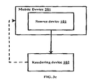
- the source device 101 may be co-located with the mobile device 201 , with the rendering device 102 located remotely from the mobile device 201 (as depicted in FIG. 3 c ).
- the source device 101 may be connected to a plurality of rendering devices 102 , with the mobile device 201 being located within the acoustic space, wherein the acoustic space is an areas such as a room, a stage, a theater, an amphitheater, a stadium and so on (as depicted in FIGS. 3 d and 3 c ).
- the source device 101 , the rendering device 102 and the mobile device 201 may be co-located within a vehicle (as depicted in FIG. 3 f ).
- the mobile device 201 may obtain the frequency characteristics of the microphone of the mobile device 201 .
- the mobile device 201 may determine the frequency characteristics using a stored profile of the mobile device 201 stored in a suitable location within the mobile device 201 or external to the mobile device 201 .
- the mobile device 201 may further determine the quality of the source signal and improve the quality of the source signal.
- the mobile device 201 may then perform calibration of the rendering devices 102 .
- the calibration may be in terms of modifying equalization settings.
- the mobile device 201 may further compensate for ambient noise.
- the mobile device 201 may communicate settings related to the calibration and the ambient noise compensation to the source device 101 .
- FIG. 4 is a flowchart illustrating the process of enhancing audio data, according to embodiments as disclosed herein.
- the mobile device 201 on detecting audio being played, obtains ( 401 ) the frequency characteristics of the microphone of the mobile device 201 .
- the mobile device 201 may determine the frequency characteristics using a stored profile of the mobile device 201 stored in a suitable location within the mobile device 201 or external to the mobile device 201 .
- the mobile device 201 may calculate the frequency characteristics of the mobile device 201 .
- the mobile device 201 further determines ( 402 ) the quality of the source signal and improves the quality of the source signal.
- the mobile device 201 then calibrates ( 403 ) the rendering devices 102 .
- the calibration may be in terms of modifying equalization settings.
- the mobile device 201 further compensates ( 404 ) for ambient noise.
- the mobile device 201 communicates the improved source signal, settings related to the calibration and the ambient noise compensation to the source device 101 .
- the various actions in method 400 may be performed in the order presented, in a different order or simultaneously. Further, in some embodiments, some actions listed in FIG. 4 may be omitted.
- FIG. 5 depicts a mobile device, according to embodiments as disclosed herein.
- the mobile device 201 comprises of a controller 501 , at least one microphone 502 , a communication interface 503 and a memory 504 .
- the controller 501 may determine the frequency characteristics of the microphone 502 .
- the controller 501 may fetch the frequency characteristics of the microphone 502 from the memory 504 .
- the controller 501 may communicate a test audio signal to the source device 101 , wherein the test audio signal may be a logarithmic test sweep signal.
- the source device 101 may play the test audio signal using the rendering device 102 .
- the controller 501 may capture the test signal from the rendering device 102 using the microphone 502 , wherein the mobile device 201 may be placed at a very close range to the rendering device 102 .
- the controller 501 may guide the user through the above-mentioned steps.
- the controller 501 may then determine the impulse response of the captured test signal.
- the controller 501 may invert the frequency characteristics of the impulse response and may determine a microphone-equalizing filter, wherein the microphone-equalizing filter may be used to compensate for the frequency characteristics of the microphone 502 .
- the controller 502 may store the microphone-equalizing filter in the memory 504 and may be used in the further steps.
- the controller 501 on detecting that audio is being played though the microphone 502 may use the detected audio signal and a suitable audio fingerprinting means to identify the audio being played. On identifying the audio, the controller 501 may fetch a small portion of a high-quality version of the detected audio signal from a location (such as the internet, the LAN, the WAN, a dedicated server and so on). The controller 501 may time align the detected audio signal and the fetched audio signal. The controller 501 may perform the time alignment by comparing the detected audio signal and time shifted versions of the fetched audio signal.
- the controller 501 may check if the source signal is of a low quality by comparing Sq with a quality threshold. If Sq is less than the threshold, then the controller 501 may determine that the source signal is of low quality.
- the controller 501 may detect a high quality source of the sound signal from a suitable location (such as the Internet, a LAN, a WAN, a dedicated server and so on) and stream the high-quality signal from the suitable location.
- the controller 501 may transmit the difference signal between the low quality and high quality signal to the source device 101 , which results in an improvement in the quality of the source signal.
- the controller 501 may determine the setup of the rendering devices (number of rendering devices, locations of the rendering devices, types of rendering devices and so on).
- the controller 501 may use the sensors of the mobile device 201 such as the magnetometer and accelerometer to measure angles with respect to the rendering devices.
- the magnetometer may provide the initial reference direction and the accelerometer may be used to give the angular displacement from the initial reference direction.
- the controller 501 may obtain the absolute angles of the locations of the rendering devices with respect to the reference position.
- the controller 501 may provide instructions to the user to point the mobile device 201 toward the rendering device and the controller 501 determines the Cartesian coordinates.
- the controller 501 may prompt the user to input the coordinates of the rendering devices.
- the controller 501 may use the microphones to triangulate and find the location of the rendering devices.
- the controller 501 may determine the relative distances of the rendering devices by providing a known reference signal to the source device 101 .
- the source device 101 may play the reference signal at periodic intervals (wherein the periodic intervals may be determined by the controller 501 ).
- the controller 501 may capture the reference signals played from the rendering devices using the microphone 502 .
- the controller 501 may determine the relative distances of the rendering devices by calculating the delays.
- the controller 501 may further check the acoustics of the acoustic space.
- the controller 501 may use impulse response (IR) method to find the frequency response, distance and loudness of the rendering devices and the acoustic space.
- the controller 501 may first send a test tone or a calibration audio signal, preferably an audio signal frequency sweep, to the rendering device (through the source device).
- the controller 501 may capture back the calibration signal using the microphone 502 .
- the controller 501 may calculate an impulse response for the broadcast calibration audio signal.
- the controller may take the inverse Fourier transform (FFT) of the ratio of the FFT of the frequency sweep signal and FFT of the received microphone signal. This impulse response may represent the quality of the audio signal in the current acoustic space.
- FFT inverse Fourier transform
- the controller 501 may calculate a crossover filler using the impulse response, wherein the crossover filter may be applied to the rendering device 102 .
- the cross-over filter may be a fourth order Butterworth filter, wherein the cut-off of the Butterworth filter may be determined by the controller 501 from the frequency response of the impulse response.
- the controller 501 may consider the point at which the amplitude of the frequency response drops to ⁇ 10 dB of the maximum amplitude over the entire frequency range as the cut-off frequency.
- the controller 501 may determine the loudness of the rendering device using the impulse response.
- the controller 501 may compute the loudness by calculating the energy of the impulse response.
- the controller 501 may use a well-known weighting filter, such as A-weights or C-weights for computation of this loudness in conjunction with the impulse response.
- the controller 501 may determine the loudness compensation by computing the average of the magnitude of all the frequency responses for the rendering device.
- the controller 501 may use the inverse of the average of the magnitude of all the frequency responses for the rendering device to match the volume of each subsequent rendering device (if any).
- the controller 501 may mimic the non-linear frequency scale of a human auditory system by passing the impulse response through a set of all-pass filters. This filtered signal is hereinafter referred to as ‘m’.
- the controller 501 may compute a finite impulse response (FIR) filter (hereinafter referred to as w), which is the minimum phase filter whose magnitude response is the inverse of m.
- FIR finite impulse response
- the controller 501 may invert the non-linear frequency scale to yield the final equalization filter by passing the FIR w through a set of all-pass filters, wherein the final equalization filter may be used to compensate the quality of rendering device.
- the controller 501 may repeat this process for all the rendering devices.
- the controller 501 may use an infinite impulse response (IIR) filter to correct the response of the rendering device.
- IIR infinite impulse response
- the controller 501 may use a combination of FIR and IIR filters may be used to correct the response of the rendering device.
- the controller 501 may calculate a delay compensation by first calculating the delay between broadcast of the calibration signal from each of the rendering devices and the corresponding receipt of such signal at the microphone, preferably through examination of the point at which the impulse repulse is at its maximum. The controller 501 may then obtain a delay compensation filter by subtracting the delay from a pre-determined maximum delay (which may be configured by the user at the source device 101 ). The controller 501 may estimate a delay filter for the subject-rendering device 102 for later compensation of any uneven timing of the previously determined impulse response.
- the controller 501 may account for the different ambient noise levels during playback of the audio signal through the rendering devices.
- the controller 501 may use the microphone 502 .
- the controller 501 On detecting a period of silence in the source signal, the controller 501 through the microphone 502 , measure ambience noise characteristics.
- the ambient noise characteristics may comprise of frequency characteristics and loudness level of noise, during this period of silence.
- the controller 501 may measure loudness using a suitable method (such as A-weights) that can mimic human hearing.
- the controller 501 may calculate the frequency response using the FFT of the detected noise signal.
- the controller 501 uses the inverse of the frequency response to calculate a digital filter (wherein the digital filter may be at least one of FIR or IIR) to compensate for the noise characteristics.
- the controller 501 may also estimate an optimum volume level of the source signal, based on the loudness level of the noise so as to keep constant power between the noise and the source signal.
- the controller 501 may communicate the digital filter and the optimum noise level to the source device 101 , which performs adjustments as per the received communication.
- FIG. 6 is a flowchart illustrating the process of determining microphone characteristics of the microphone of a mobile device, according to embodiments as disclosed herein.
- the mobile device 201 communicates ( 601 ) a test audio signal to the source device 101 , wherein the test audio signal may be a logarithmic test sweep signal.
- the source device 101 plays ( 602 ) the test audio signal using the rendering device 102 .
- the mobile device 201 captures ( 603 ) the test signal from the rendering device 102 using the microphone 502 , wherein the mobile device 201 may be placed at a very close range to the rendering device 102 .
- the mobile device 201 determines ( 604 ) the impulse response of the captured test signal.
- the mobile device 201 inverts ( 605 ) the frequency characteristics of the impulse response and determines ( 606 ) a microphone-equalizing filter, wherein the microphone-equalizing filter may be used to compensate for the frequency characteristics of the microphone 502 .
- the controller 502 stores ( 607 ) the microphone equalizing filter in the memory 504 and may be used in the further steps.
- the various actions in method 600 may be performed in the order presented, in a different order or simultaneously. Further, in some, embodiments, some actions listed in FIG. 6 may be omitted.
- FIG. 7 is a flowchart illustrating the process of detecting quality of a source signal and improving the quality of the source signal, according to embodiments as disclosed herein.
- the mobile device 201 on detecting that audio is being played though the microphone 502 identifies ( 701 ) the audio being, played using the detected audio signal and a suitable audio fingerprinting means. On identifying the audio, the mobile device 201 fetches ( 702 ) a small portion of a high-quality version of the detected audio signal from a location (such as the internet, the LAN, the WAN, a dedicated server and so on). The mobile device 201 time aligns ( 703 ) the detected audio signal and the fetched audio signal by comparing the detected audio signal and time shifted versions of the fetched audio signal.
- a location such as the internet, the LAN, the WAN, a dedicated server and so on.
- the mobile device 201 checks ( 705 ) if the source signal is of a low quality by comparing Sq with a quality threshold. If Sq is less than the threshold, then the mobile device 201 may determine that the source signal is of low quality.
- the mobile device 201 detects ( 706 ) a high quality source of the sound signal from a suitable location (such as the Internet, a LAN, a WAN, a dedicated server and so on) and streams ( 707 ) the high-quality signal from the suitable location.
- the mobile device 201 transmits ( 708 ) the difference signal between the low quality and high quality signal to the source device 101 , which results in an improvement in the quality of the source signal.
- the various actions in method 700 may be performed in the order presented, in a different order or simultaneously. Further, in some embodiments, some actions listed in FIG. 7 may be omitted.
- FIGS. 8 a and 8 b are flowcharts illustrating the process of calibrating at least one rendering device using a mobile device, according to embodiments as disclosed herein.
- the mobile device 201 may determine the setup of the rendering devices (number of rendering devices, locations of the rendering devices, types of rendering devices and so on).
- the mobile device 201 may use the sensors of the mobile device 201 such as the magnetometer and accelerometer to measure angles with respect to the rendering devices.
- the magnetometer provides ( 801 ) the initial reference direction and the accelerometer provides ( 802 ) the angular displacement from the initial reference direction.
- the mobile device 201 obtains ( 803 ) the absolute angles of the locations of the rendering devices with respect to the reference position in terms of Cartesian coordinates.
- the mobile device 201 may provide instructions to the user to point the mobile device 201 toward the rendering device 102 . In another embodiment herein, the mobile device 201 may prompt the user to input the coordinates of the rendering devices. In another embodiment herein, the mobile device 201 may use the microphones to triangulate and find the location of the rendering devices.
- the mobile device 201 determines the relative distances of the rendering devices by providing ( 804 ) a known reference signal to the source device 101 .
- the source device 101 plays ( 805 ) the reference signal at periodic intervals (wherein the periodic intervals may be determined by the mobile device 201 ).
- the mobile device 201 captures ( 806 ) the reference signals played from the rendering devices using the microphone 502 .
- the mobile device 201 determines ( 807 ) the relative distances of the rendering devices by calculating the delays of the captured reference signals.
- the mobile device 201 may further check the acoustics of the acoustic space.
- the mobile device 201 uses impulse response (IR) method to find the frequency response, distance and loudness of the rendering devices and the acoustic space.
- the mobile device 201 first sends ( 808 ) a test tone or a calibration audio signal, preferably an audio signal frequency sweep signal, to the rendering device 102 (through the source device 101 ).
- the mobile device 201 captures ( 809 ) back the calibration signal using the microphone 502 .
- the mobile device 201 calculates ( 810 ) an impulse response for the frequency sweep signal by taking the inverse Fourier transform (IFT) of the ratio of the FFT (Fast Fourier Transform) of the frequency sweep signal and FFT of the received microphone signal.
- IFT inverse Fourier transform
- the mobile device 201 calculates ( 811 ) a crossover filter using the impulse response, wherein the crossover filter may be applied to the rendering device 102 .
- the cross-over filter may be a fourth order Butterworth filter, wherein the cut-off of the Butterworth filter may be determined by the mobile device 201 from the frequency response of the impulse response.
- the Mobile device 201 may consider the point at which the amplitude of the frequency response drops to ⁇ 10 dB of the maximum amplitude over the entire frequency range as the cut-off frequency.
- the mobile device 201 determines ( 812 ) the loudness of the rendering device using the impulse response.
- the mobile device 201 may compute the loudness by calculating the energy of the impulse response.
- the mobile device 201 may use a well known weighting filter, such as A-weights or C-weights for computation of this loudness in conjunction with the impulse response.
- the mobile device 201 determines ( 813 ) the loudness compensation by computing the average of the magnitude of all the frequency responses for the rendering device.
- the mobile device 201 may use the inverse of the average of the magnitude of all the frequency responses for the rendering device to match the volume of each subsequent rendering device (if any).
- the mobile device 201 mimics ( 814 ) the non-linear frequency scale of a human auditory system by passing the impulse response through a set of all-pass filters.
- This filtered signal is hereinafter referred to as ‘m’.
- the mobile device 201 computes ( 815 ) a finite impulse response (FIR) filter (hereinafter referred to as w), which is the minimum phase filter whose magnitude response is the inverse of m.
- the mobile device 201 inverts ( 816 ) the non-linear frequency scale to yield the final equalization filter by passing the FIR w through a set of all-pass filters, wherein the final equalization filter may be used to compensate the quality of rendering device.
- the mobile device 201 repeats ( 817 ) this process for all the rendering devices.
- the mobile device 201 may use an infinite impulse response (IIR) filter to correct the response of the rendering device.
- IIR infinite impulse response
- the mobile device 201 may use a combination of FIR and IIR filters may be used to correct the response of the rendering device.
- the mobile device 201 calculates a delay compensation by first calculating the delay between broadcast of the calibration signal from each of the rendering devices and the corresponding receipt of such signal at the microphone, preferably through examination of the point at which the impulse repulse is at its maximum. The mobile device 201 then obtains a delay compensation filter by subtracting the delay from a pre-determined maximum delay (which may be configured by the user at the source device 101 ). The mobile device 201 may estimate a delay filter for the subject-rendering device 102 for later compensation of any uneven timing of the previously determined impulse response.
- method 800 may be performed in the order presented, in a different order or simultaneously. Further, in some embodiments, some actions listed in FIGS. 8 a and 8 b may be omitted.
- FIG. 9 is a flowchart illustrating the process of improving acoustic quality based on ambient noise, according to embodiments as disclosed herein.
- the mobile device 201 may account for the different ambient noise levels during playback of the audio signal through the rendering devices.
- the mobile device 201 may use the microphone 502 .
- the mobile device 201 On detecting a period of silence in the source signal, the mobile device 201 through the microphone 502 , measures ( 901 ) ambience noise characteristics.
- the ambient noise characteristics may comprise of frequency characteristics and loudness level of noise, during this period of silence.
- the mobile device 201 measures ( 902 ) loudness using a suitable method (such as A-weights) that can mimic human hearing.
- the mobile device 201 calculates ( 903 ) the frequency response using the FFT of the detected noise signal.
- the mobile device 201 calculates ( 904 ) a digital filter (wherein the digital filter may be at least one of FIR or IIR) using the inverse of the frequency response, to compensate for the noise characteristics.
- the mobile device 201 also estimates ( 905 ) an optimum volume level of the source signal, based on the loudness level of the noise so as to keep constant power between the noise and the source signal.
- the mobile device 201 communicates ( 906 ) the digital filter and the optimum noise level to the source device 101 , which performs adjustments as per the received communication.
- the various actions in method 900 may be performed in the order presented, in a different order or simultaneously. Further, in some embodiments, some actions listed in FIG. 9 may be omitted.
- FIG. 10 illustrates a computing environment implementing the method for enhancing audio quality, according to embodiments as disclosed herein.
- the computing environment 1001 comprises at least one processing unit 1004 that is equipped with a control unit 1002 and an Arithmetic Logic Unit (ALU) 1003 , a memory 1005 , a storage unit 1006 , plurality of networking devices 1010 and a plurality Input output (I/O) devices 1007 .
- the processing unit 1004 is responsible for processing the instructions of the algorithm.
- the processing unit 1004 receives commands from the control unit in order to perform its processing. Further, any logical and arithmetic operations involved in the execution of the instructions are computed with the help of the ALU 1003 .
- the overall computing environment 1001 may be composed of multiple homogeneous and/or heterogeneous cores, multiple CPUs of different kinds, special media and other accelerators.
- the processing unit 1004 is responsible for processing the instructions of the algorithm. Further, the plurality of processing units 1004 may be located on a single chip or over multiple chips.
- the algorithm comprising of instructions and codes required for the implementation are stored in either the memory unit 1005 or the storage 1006 or both. At the time of execution, the instructions may be fetched from the corresponding memory 1005 and/or storage 1006 , and executed by the processing unit 1004 .
- networking devices 1008 or external I/O devices 1007 may be connected to the computing environment to support the implementation through the networking unit and the I/O device unit.
- Embodiments disclosed herein enable detection and improvement of the quality of the audio signal using a mobile device.
- Embodiments herein use the audio attributes such as bit rate of audio and the network link quality and along with fingerprint of audio to determine the audio quality. Since most of the audio, which is stored or streamed, is compressed using lossy compression, there may be missing portions of audio. Embodiments disclosed herein determine this loss and enhances audio by streaming the remainder portion of audio.
- Embodiments disclosed herein enable an improvement in the sound quality rendered by rendering devices. By emitting the test audio signal from the source device and measuring the test audio signal using microphones, embodiments disclosed herein understand the acoustics characteristics of the rendering device. Embodiments disclosed herein then detect variation in the frequency response, loudness and timing characteristics using impulse responses and corrects for them.
- Embodiments disclosed herein also compensate for the noise in the acoustic space.
- embodiments disclosed herein determine the reverberation and ambient noise levels and their frequency characteristics in the acoustic space and changes the digital filters and volumes of the source signal to compensate for the varying noise levels in the acoustic space.
Abstract
Description
Sq=(H*H+O*O)/(H—O)*(H—O)
Where H is the fetched audio signal, O is the detected audio signal and Sq is the quality of the detected audio signal. The
Sq=(H*H+O*O)/(H—O)*(H—O)
Where H is the fetched audio signal, O is the detected audio signal and Sq is the quality of the detected audio signal. The
Claims (21)
Priority Applications (4)
| Application Number | Priority Date | Filing Date | Title |
|---|---|---|---|
| US14/449,159 US9565497B2 (en) | 2013-08-01 | 2014-08-01 | Enhancing audio using a mobile device |
| US15/157,135 US9706305B2 (en) | 2013-08-01 | 2016-05-17 | Enhancing audio using a mobile device |
| US15/157,123 US9848263B2 (en) | 2013-08-01 | 2016-05-17 | Enhancing audio using a mobile device |
| US15/157,131 US9699556B2 (en) | 2013-08-01 | 2016-05-17 | Enhancing audio using a mobile device |
Applications Claiming Priority (2)
| Application Number | Priority Date | Filing Date | Title |
|---|---|---|---|
| US201361861138P | 2013-08-01 | 2013-08-01 | |
| US14/449,159 US9565497B2 (en) | 2013-08-01 | 2014-08-01 | Enhancing audio using a mobile device |
Related Child Applications (3)
| Application Number | Title | Priority Date | Filing Date |
|---|---|---|---|
| US15/157,123 Division US9848263B2 (en) | 2013-08-01 | 2016-05-17 | Enhancing audio using a mobile device |
| US15/157,131 Division US9699556B2 (en) | 2013-08-01 | 2016-05-17 | Enhancing audio using a mobile device |
| US15/157,135 Division US9706305B2 (en) | 2013-08-01 | 2016-05-17 | Enhancing audio using a mobile device |
Publications (2)
| Publication Number | Publication Date |
|---|---|
| US20160035337A1 US20160035337A1 (en) | 2016-02-04 |
| US9565497B2 true US9565497B2 (en) | 2017-02-07 |
Family
ID=55180668
Family Applications (4)
| Application Number | Title | Priority Date | Filing Date |
|---|---|---|---|
| US14/449,159 Active 2034-08-19 US9565497B2 (en) | 2013-08-01 | 2014-08-01 | Enhancing audio using a mobile device |
| US15/157,135 Active US9706305B2 (en) | 2013-08-01 | 2016-05-17 | Enhancing audio using a mobile device |
| US15/157,123 Active US9848263B2 (en) | 2013-08-01 | 2016-05-17 | Enhancing audio using a mobile device |
| US15/157,131 Active US9699556B2 (en) | 2013-08-01 | 2016-05-17 | Enhancing audio using a mobile device |
Family Applications After (3)
| Application Number | Title | Priority Date | Filing Date |
|---|---|---|---|
| US15/157,135 Active US9706305B2 (en) | 2013-08-01 | 2016-05-17 | Enhancing audio using a mobile device |
| US15/157,123 Active US9848263B2 (en) | 2013-08-01 | 2016-05-17 | Enhancing audio using a mobile device |
| US15/157,131 Active US9699556B2 (en) | 2013-08-01 | 2016-05-17 | Enhancing audio using a mobile device |
Country Status (1)
| Country | Link |
|---|---|
| US (4) | US9565497B2 (en) |
Cited By (1)
| Publication number | Priority date | Publication date | Assignee | Title |
|---|---|---|---|---|
| US11937076B2 (en) | 2019-07-03 | 2024-03-19 | Hewlett-Packard Development Copmany, L.P. | Acoustic echo cancellation |
Families Citing this family (97)
| Publication number | Priority date | Publication date | Assignee | Title |
|---|---|---|---|---|
| US9084058B2 (en) | 2011-12-29 | 2015-07-14 | Sonos, Inc. | Sound field calibration using listener localization |
| US9219460B2 (en) | 2014-03-17 | 2015-12-22 | Sonos, Inc. | Audio settings based on environment |
| US9706323B2 (en) | 2014-09-09 | 2017-07-11 | Sonos, Inc. | Playback device calibration |
| US9690539B2 (en) | 2012-06-28 | 2017-06-27 | Sonos, Inc. | Speaker calibration user interface |
| US9106192B2 (en) | 2012-06-28 | 2015-08-11 | Sonos, Inc. | System and method for device playback calibration |
| US9565497B2 (en) | 2013-08-01 | 2017-02-07 | Caavo Inc. | Enhancing audio using a mobile device |
| US9264839B2 (en) | 2014-03-17 | 2016-02-16 | Sonos, Inc. | Playback device configuration based on proximity detection |
| US9910634B2 (en) | 2014-09-09 | 2018-03-06 | Sonos, Inc. | Microphone calibration |
| US9952825B2 (en) | 2014-09-09 | 2018-04-24 | Sonos, Inc. | Audio processing algorithms |
| US9891881B2 (en) | 2014-09-09 | 2018-02-13 | Sonos, Inc. | Audio processing algorithm database |
| US10127006B2 (en) | 2014-09-09 | 2018-11-13 | Sonos, Inc. | Facilitating calibration of an audio playback device |
| EP3001701B1 (en) * | 2014-09-24 | 2018-11-14 | Harman Becker Automotive Systems GmbH | Audio reproduction systems and methods |
| WO2016172593A1 (en) | 2015-04-24 | 2016-10-27 | Sonos, Inc. | Playback device calibration user interfaces |
| US10664224B2 (en) | 2015-04-24 | 2020-05-26 | Sonos, Inc. | Speaker calibration user interface |
| US10237839B2 (en) * | 2015-06-15 | 2019-03-19 | Qualcomm Incorporated | Phase tracking in training fields |
| US9729118B2 (en) * | 2015-07-24 | 2017-08-08 | Sonos, Inc. | Loudness matching |
| US9538305B2 (en) | 2015-07-28 | 2017-01-03 | Sonos, Inc. | Calibration error conditions |
| US9590580B1 (en) * | 2015-09-13 | 2017-03-07 | Guoguang Electric Company Limited | Loudness-based audio-signal compensation |
| US9693165B2 (en) | 2015-09-17 | 2017-06-27 | Sonos, Inc. | Validation of audio calibration using multi-dimensional motion check |
| CN108028985B (en) | 2015-09-17 | 2020-03-13 | 搜诺思公司 | Method for computing device |
| US10867019B2 (en) * | 2015-10-21 | 2020-12-15 | Nec Corporation | Personal authentication device, personal authentication method, and personal authentication program using acoustic signal propagation |
| US9743207B1 (en) | 2016-01-18 | 2017-08-22 | Sonos, Inc. | Calibration using multiple recording devices |
| US10003899B2 (en) | 2016-01-25 | 2018-06-19 | Sonos, Inc. | Calibration with particular locations |
| US11106423B2 (en) * | 2016-01-25 | 2021-08-31 | Sonos, Inc. | Evaluating calibration of a playback device |
| US9772817B2 (en) | 2016-02-22 | 2017-09-26 | Sonos, Inc. | Room-corrected voice detection |
| US10095470B2 (en) | 2016-02-22 | 2018-10-09 | Sonos, Inc. | Audio response playback |
| US9965247B2 (en) | 2016-02-22 | 2018-05-08 | Sonos, Inc. | Voice controlled media playback system based on user profile |
| US10509626B2 (en) | 2016-02-22 | 2019-12-17 | Sonos, Inc | Handling of loss of pairing between networked devices |
| US9947316B2 (en) | 2016-02-22 | 2018-04-17 | Sonos, Inc. | Voice control of a media playback system |
| US10264030B2 (en) | 2016-02-22 | 2019-04-16 | Sonos, Inc. | Networked microphone device control |
| US9860662B2 (en) | 2016-04-01 | 2018-01-02 | Sonos, Inc. | Updating playback device configuration information based on calibration data |
| US9864574B2 (en) | 2016-04-01 | 2018-01-09 | Sonos, Inc. | Playback device calibration based on representation spectral characteristics |
| US9763018B1 (en) | 2016-04-12 | 2017-09-12 | Sonos, Inc. | Calibration of audio playback devices |
| US9978390B2 (en) | 2016-06-09 | 2018-05-22 | Sonos, Inc. | Dynamic player selection for audio signal processing |
| US9794710B1 (en) | 2016-07-15 | 2017-10-17 | Sonos, Inc. | Spatial audio correction |
| US9860670B1 (en) | 2016-07-15 | 2018-01-02 | Sonos, Inc. | Spectral correction using spatial calibration |
| US10372406B2 (en) | 2016-07-22 | 2019-08-06 | Sonos, Inc. | Calibration interface |
| US10459684B2 (en) | 2016-08-05 | 2019-10-29 | Sonos, Inc. | Calibration of a playback device based on an estimated frequency response |
| US10115400B2 (en) | 2016-08-05 | 2018-10-30 | Sonos, Inc. | Multiple voice services |
| US9693164B1 (en) * | 2016-08-05 | 2017-06-27 | Sonos, Inc. | Determining direction of networked microphone device relative to audio playback device |
| US9942678B1 (en) | 2016-09-27 | 2018-04-10 | Sonos, Inc. | Audio playback settings for voice interaction |
| US10181323B2 (en) | 2016-10-19 | 2019-01-15 | Sonos, Inc. | Arbitration-based voice recognition |
| CN106782585B (en) * | 2017-01-26 | 2020-03-20 | 芋头科技(杭州)有限公司 | Pickup method and system based on microphone array |
| US10475449B2 (en) | 2017-08-07 | 2019-11-12 | Sonos, Inc. | Wake-word detection suppression |
| KR102409376B1 (en) * | 2017-08-09 | 2022-06-15 | 삼성전자주식회사 | Display apparatus and control method thereof |
| US10048930B1 (en) | 2017-09-08 | 2018-08-14 | Sonos, Inc. | Dynamic computation of system response volume |
| US10446165B2 (en) | 2017-09-27 | 2019-10-15 | Sonos, Inc. | Robust short-time fourier transform acoustic echo cancellation during audio playback |
| US10621981B2 (en) | 2017-09-28 | 2020-04-14 | Sonos, Inc. | Tone interference cancellation |
| US10482868B2 (en) | 2017-09-28 | 2019-11-19 | Sonos, Inc. | Multi-channel acoustic echo cancellation |
| US10466962B2 (en) | 2017-09-29 | 2019-11-05 | Sonos, Inc. | Media playback system with voice assistance |
| US11032580B2 (en) | 2017-12-18 | 2021-06-08 | Dish Network L.L.C. | Systems and methods for facilitating a personalized viewing experience |
| US11343614B2 (en) | 2018-01-31 | 2022-05-24 | Sonos, Inc. | Device designation of playback and network microphone device arrangements |
| US10365885B1 (en) | 2018-02-21 | 2019-07-30 | Sling Media Pvt. Ltd. | Systems and methods for composition of audio content from multi-object audio |
| US10524048B2 (en) * | 2018-04-13 | 2019-12-31 | Bose Corporation | Intelligent beam steering in microphone array |
| US11232807B2 (en) | 2018-04-27 | 2022-01-25 | Dolby Laboratories Licensing Corporation | Background noise estimation using gap confidence |
| US11175880B2 (en) | 2018-05-10 | 2021-11-16 | Sonos, Inc. | Systems and methods for voice-assisted media content selection |
| US10959029B2 (en) | 2018-05-25 | 2021-03-23 | Sonos, Inc. | Determining and adapting to changes in microphone performance of playback devices |
| GB2574803B (en) * | 2018-06-11 | 2022-12-07 | Xmos Ltd | Communication between audio devices |
| US10681460B2 (en) | 2018-06-28 | 2020-06-09 | Sonos, Inc. | Systems and methods for associating playback devices with voice assistant services |
| US10299061B1 (en) | 2018-08-28 | 2019-05-21 | Sonos, Inc. | Playback device calibration |
| US11076035B2 (en) | 2018-08-28 | 2021-07-27 | Sonos, Inc. | Do not disturb feature for audio notifications |
| US11206484B2 (en) | 2018-08-28 | 2021-12-21 | Sonos, Inc. | Passive speaker authentication |
| US10461710B1 (en) | 2018-08-28 | 2019-10-29 | Sonos, Inc. | Media playback system with maximum volume setting |
| US10587430B1 (en) | 2018-09-14 | 2020-03-10 | Sonos, Inc. | Networked devices, systems, and methods for associating playback devices based on sound codes |
| US11024331B2 (en) | 2018-09-21 | 2021-06-01 | Sonos, Inc. | Voice detection optimization using sound metadata |
| US10811015B2 (en) | 2018-09-25 | 2020-10-20 | Sonos, Inc. | Voice detection optimization based on selected voice assistant service |
| US11100923B2 (en) | 2018-09-28 | 2021-08-24 | Sonos, Inc. | Systems and methods for selective wake word detection using neural network models |
| US11899519B2 (en) | 2018-10-23 | 2024-02-13 | Sonos, Inc. | Multiple stage network microphone device with reduced power consumption and processing load |
| EP3654249A1 (en) | 2018-11-15 | 2020-05-20 | Snips | Dilated convolutions and gating for efficient keyword spotting |
| US11183183B2 (en) | 2018-12-07 | 2021-11-23 | Sonos, Inc. | Systems and methods of operating media playback systems having multiple voice assistant services |
| US11132989B2 (en) | 2018-12-13 | 2021-09-28 | Sonos, Inc. | Networked microphone devices, systems, and methods of localized arbitration |
| US10602268B1 (en) | 2018-12-20 | 2020-03-24 | Sonos, Inc. | Optimization of network microphone devices using noise classification |
| US10867604B2 (en) | 2019-02-08 | 2020-12-15 | Sonos, Inc. | Devices, systems, and methods for distributed voice processing |
| US11315556B2 (en) | 2019-02-08 | 2022-04-26 | Sonos, Inc. | Devices, systems, and methods for distributed voice processing by transmitting sound data associated with a wake word to an appropriate device for identification |
| CN110109644B (en) * | 2019-04-10 | 2020-11-17 | 广州视源电子科技股份有限公司 | Method, device and system for determining and processing equalization parameters of electronic equipment |
| US11120794B2 (en) | 2019-05-03 | 2021-09-14 | Sonos, Inc. | Voice assistant persistence across multiple network microphone devices |
| FR3096197B1 (en) | 2019-05-14 | 2021-04-23 | Psa Automobiles Sa | METHOD OF DETERMINING THE AUDIO PERFORMANCE OF AN AMPLIFIER |
| US11200894B2 (en) | 2019-06-12 | 2021-12-14 | Sonos, Inc. | Network microphone device with command keyword eventing |
| US10586540B1 (en) | 2019-06-12 | 2020-03-10 | Sonos, Inc. | Network microphone device with command keyword conditioning |
| US11361756B2 (en) | 2019-06-12 | 2022-06-14 | Sonos, Inc. | Conditional wake word eventing based on environment |
| US11138969B2 (en) | 2019-07-31 | 2021-10-05 | Sonos, Inc. | Locally distributed keyword detection |
| US10871943B1 (en) | 2019-07-31 | 2020-12-22 | Sonos, Inc. | Noise classification for event detection |
| US11138975B2 (en) | 2019-07-31 | 2021-10-05 | Sonos, Inc. | Locally distributed keyword detection |
| US10734965B1 (en) | 2019-08-12 | 2020-08-04 | Sonos, Inc. | Audio calibration of a portable playback device |
| CN110536023A (en) * | 2019-09-29 | 2019-12-03 | 李欣钊 | A kind of system intelligently adjusting device for prompt tone of electronic based on spatial volume |
| US11189286B2 (en) | 2019-10-22 | 2021-11-30 | Sonos, Inc. | VAS toggle based on device orientation |
| US11817114B2 (en) | 2019-12-09 | 2023-11-14 | Dolby Laboratories Licensing Corporation | Content and environmentally aware environmental noise compensation |
| US11200900B2 (en) | 2019-12-20 | 2021-12-14 | Sonos, Inc. | Offline voice control |
| US11562740B2 (en) | 2020-01-07 | 2023-01-24 | Sonos, Inc. | Voice verification for media playback |
| US11308958B2 (en) | 2020-02-07 | 2022-04-19 | Sonos, Inc. | Localized wakeword verification |
| EP4133752A1 (en) * | 2020-04-07 | 2023-02-15 | Qualcomm Incorporated | Method and apparatus for location-based audio signal compensation |
| US11308962B2 (en) | 2020-05-20 | 2022-04-19 | Sonos, Inc. | Input detection windowing |
| US11727919B2 (en) | 2020-05-20 | 2023-08-15 | Sonos, Inc. | Memory allocation for keyword spotting engines |
| US11482224B2 (en) | 2020-05-20 | 2022-10-25 | Sonos, Inc. | Command keywords with input detection windowing |
| CN111722109B (en) * | 2020-06-28 | 2023-05-02 | 瑞声科技(新加坡)有限公司 | Method and apparatus for measuring motor system distortion, and computer readable storage medium |
| US11698771B2 (en) | 2020-08-25 | 2023-07-11 | Sonos, Inc. | Vocal guidance engines for playback devices |
| CN112929808A (en) * | 2021-02-05 | 2021-06-08 | 四川湖山电器股份有限公司 | Method, module and system for detecting whether campus broadcasting equipment can work normally |
Citations (29)
| Publication number | Priority date | Publication date | Assignee | Title |
|---|---|---|---|---|
| US4758908A (en) | 1986-09-12 | 1988-07-19 | Fred James | Method and apparatus for substituting a higher quality audio soundtrack for a lesser quality audio soundtrack during reproduction of the lesser quality audio soundtrack and a corresponding visual picture |
| US20030169891A1 (en) | 2002-03-08 | 2003-09-11 | Ryan Jim G. | Low-noise directional microphone system |
| US20040240676A1 (en) | 2003-05-26 | 2004-12-02 | Hiroyuki Hashimoto | Sound field measurement device |
| US20050175190A1 (en) | 2004-02-09 | 2005-08-11 | Microsoft Corporation | Self-descriptive microphone array |
| US20060098827A1 (en) * | 2002-06-05 | 2006-05-11 | Thomas Paddock | Acoustical virtual reality engine and advanced techniques for enhancing delivered sound |
| US20080031471A1 (en) | 2006-05-19 | 2008-02-07 | Tim Haulick | System for equalizing an acoustic signal |
| US20080037804A1 (en) | 2006-08-01 | 2008-02-14 | Dts, Inc. | Neural network filtering techniques for compensating linear and non-linear distortion of an audio transducer |
| US20080226098A1 (en) | 2005-04-29 | 2008-09-18 | Tim Haulick | Detection and suppression of wind noise in microphone signals |
| US20080285775A1 (en) * | 2007-04-25 | 2008-11-20 | Markus Christoph | Sound tuning method |
| US20100054519A1 (en) | 2008-09-03 | 2010-03-04 | Mulvey James P | Audio Communication System |
| US20100064218A1 (en) | 2008-09-09 | 2010-03-11 | Apple Inc. | Audio user interface |
| US20100272270A1 (en) * | 2005-09-02 | 2010-10-28 | Harman International Industries, Incorporated | Self-calibrating loudspeaker system |
| US20110002471A1 (en) | 2009-07-02 | 2011-01-06 | Conexant Systems, Inc. | Systems and methods for transducer calibration and tuning |
| US20110064258A1 (en) * | 2008-04-21 | 2011-03-17 | Snaps Networks, Inc | Electrical System for a Speaker and its Control |
| US20110116642A1 (en) | 2009-11-16 | 2011-05-19 | Harman International Industries, Incorporated | Audio System with Portable Audio Enhancement Device |
| US20120140936A1 (en) * | 2009-08-03 | 2012-06-07 | Imax Corporation | Systems and Methods for Monitoring Cinema Loudspeakers and Compensating for Quality Problems |
| US20120250900A1 (en) | 2011-03-31 | 2012-10-04 | Sakai Juri | Signal processing apparatus, signal processing method, and program |
| US8300837B2 (en) | 2006-10-18 | 2012-10-30 | Dts, Inc. | System and method for compensating memoryless non-linear distortion of an audio transducer |
| US20130066453A1 (en) * | 2010-05-06 | 2013-03-14 | Dolby Laboratories Licensing Corporation | Audio system equalization for portable media playback devices |
| US20130070928A1 (en) | 2011-09-21 | 2013-03-21 | Daniel P. W. Ellis | Methods, systems, and media for mobile audio event recognition |
| US20140003625A1 (en) | 2012-06-28 | 2014-01-02 | Sonos, Inc | System and Method for Device Playback Calibration |
| US8688249B2 (en) * | 2006-04-19 | 2014-04-01 | Sonita Logic Limted | Processing audio input signals |
| US20140142958A1 (en) | 2012-10-15 | 2014-05-22 | Digimarc Corporation | Multi-mode audio recognition and auxiliary data encoding and decoding |
| US20150156588A1 (en) * | 2013-12-02 | 2015-06-04 | Chris Kyriakakis | Audio Output Device Specific Audio Processing |
| US20150189457A1 (en) * | 2013-12-30 | 2015-07-02 | Aliphcom | Interactive positioning of perceived audio sources in a transformed reproduced sound field including modified reproductions of multiple sound fields |
| US20150223004A1 (en) * | 2012-09-18 | 2015-08-06 | Orange | Optimized Calibration of a Multi-Loudspeaker Sound Playback System |
| US20150304791A1 (en) * | 2013-01-07 | 2015-10-22 | Dolby Laboratories Licensing Corporation | Virtual height filter for reflected sound rendering using upward firing drivers |
| US20150372761A1 (en) | 2014-06-23 | 2015-12-24 | Rockwell Automation Technologies, Inc. | Photoelectric sensor with tone modulation |
| US20150378666A1 (en) | 2014-06-27 | 2015-12-31 | Blackberry Limited | Mobile electronic device and method for controlling a media player device to play back media |
Family Cites Families (6)
| Publication number | Priority date | Publication date | Assignee | Title |
|---|---|---|---|---|
| US2458641A (en) * | 1945-05-08 | 1949-01-11 | Rca Corp | Method and apparatus for controlling frequency characteristics in sound recording |
| US4888808A (en) * | 1987-03-23 | 1989-12-19 | Matsushita Electric Industrial Co., Ltd. | Digital equalizer apparatus enabling separate phase and amplitude characteristic modification |
| ATE420539T1 (en) | 2003-05-13 | 2009-01-15 | Harman Becker Automotive Sys | METHOD AND SYSTEM FOR ADAPTIVE COMPENSATION OF MICROPHONE INEQUALITIES |
| DE102008046048A1 (en) * | 2008-09-08 | 2010-03-11 | Sennheiser Electronic Gmbh & Co. Kg | Entertainment system and listener |
| EP2521377A1 (en) | 2011-05-06 | 2012-11-07 | Jacoti BVBA | Personal communication device with hearing support and method for providing the same |
| US9565497B2 (en) | 2013-08-01 | 2017-02-07 | Caavo Inc. | Enhancing audio using a mobile device |
-
2014
- 2014-08-01 US US14/449,159 patent/US9565497B2/en active Active
-
2016
- 2016-05-17 US US15/157,135 patent/US9706305B2/en active Active
- 2016-05-17 US US15/157,123 patent/US9848263B2/en active Active
- 2016-05-17 US US15/157,131 patent/US9699556B2/en active Active
Patent Citations (34)
| Publication number | Priority date | Publication date | Assignee | Title |
|---|---|---|---|---|
| US4758908A (en) | 1986-09-12 | 1988-07-19 | Fred James | Method and apparatus for substituting a higher quality audio soundtrack for a lesser quality audio soundtrack during reproduction of the lesser quality audio soundtrack and a corresponding visual picture |
| US20030169891A1 (en) | 2002-03-08 | 2003-09-11 | Ryan Jim G. | Low-noise directional microphone system |
| US20060098827A1 (en) * | 2002-06-05 | 2006-05-11 | Thomas Paddock | Acoustical virtual reality engine and advanced techniques for enhancing delivered sound |
| US20040240676A1 (en) | 2003-05-26 | 2004-12-02 | Hiroyuki Hashimoto | Sound field measurement device |
| US20050175190A1 (en) | 2004-02-09 | 2005-08-11 | Microsoft Corporation | Self-descriptive microphone array |
| US20080226098A1 (en) | 2005-04-29 | 2008-09-18 | Tim Haulick | Detection and suppression of wind noise in microphone signals |
| US20100272270A1 (en) * | 2005-09-02 | 2010-10-28 | Harman International Industries, Incorporated | Self-calibrating loudspeaker system |
| US8688249B2 (en) * | 2006-04-19 | 2014-04-01 | Sonita Logic Limted | Processing audio input signals |
| US20080031471A1 (en) | 2006-05-19 | 2008-02-07 | Tim Haulick | System for equalizing an acoustic signal |
| US20080037804A1 (en) | 2006-08-01 | 2008-02-14 | Dts, Inc. | Neural network filtering techniques for compensating linear and non-linear distortion of an audio transducer |
| US7593535B2 (en) | 2006-08-01 | 2009-09-22 | Dts, Inc. | Neural network filtering techniques for compensating linear and non-linear distortion of an audio transducer |
| US8300837B2 (en) | 2006-10-18 | 2012-10-30 | Dts, Inc. | System and method for compensating memoryless non-linear distortion of an audio transducer |
| US20080285775A1 (en) * | 2007-04-25 | 2008-11-20 | Markus Christoph | Sound tuning method |
| US8588431B2 (en) * | 2008-04-21 | 2013-11-19 | Snap Networks, Inc. | Electrical system for a speaker and its control |
| US20110064258A1 (en) * | 2008-04-21 | 2011-03-17 | Snaps Networks, Inc | Electrical System for a Speaker and its Control |
| US20140064521A1 (en) * | 2008-04-21 | 2014-03-06 | Snap Networks Pvt Ltd. | Electrical system for a speaker and its control |
| US20100054519A1 (en) | 2008-09-03 | 2010-03-04 | Mulvey James P | Audio Communication System |
| US20100064218A1 (en) | 2008-09-09 | 2010-03-11 | Apple Inc. | Audio user interface |
| US8898568B2 (en) | 2008-09-09 | 2014-11-25 | Apple Inc. | Audio user interface |
| US8682002B2 (en) | 2009-07-02 | 2014-03-25 | Conexant Systems, Inc. | Systems and methods for transducer calibration and tuning |
| US20110002471A1 (en) | 2009-07-02 | 2011-01-06 | Conexant Systems, Inc. | Systems and methods for transducer calibration and tuning |
| US20120140936A1 (en) * | 2009-08-03 | 2012-06-07 | Imax Corporation | Systems and Methods for Monitoring Cinema Loudspeakers and Compensating for Quality Problems |
| US20110116642A1 (en) | 2009-11-16 | 2011-05-19 | Harman International Industries, Incorporated | Audio System with Portable Audio Enhancement Device |
| US20130066453A1 (en) * | 2010-05-06 | 2013-03-14 | Dolby Laboratories Licensing Corporation | Audio system equalization for portable media playback devices |
| US20120250900A1 (en) | 2011-03-31 | 2012-10-04 | Sakai Juri | Signal processing apparatus, signal processing method, and program |
| US20130070928A1 (en) | 2011-09-21 | 2013-03-21 | Daniel P. W. Ellis | Methods, systems, and media for mobile audio event recognition |
| US20140003625A1 (en) | 2012-06-28 | 2014-01-02 | Sonos, Inc | System and Method for Device Playback Calibration |
| US20150223004A1 (en) * | 2012-09-18 | 2015-08-06 | Orange | Optimized Calibration of a Multi-Loudspeaker Sound Playback System |
| US20140142958A1 (en) | 2012-10-15 | 2014-05-22 | Digimarc Corporation | Multi-mode audio recognition and auxiliary data encoding and decoding |
| US20150304791A1 (en) * | 2013-01-07 | 2015-10-22 | Dolby Laboratories Licensing Corporation | Virtual height filter for reflected sound rendering using upward firing drivers |
| US20150156588A1 (en) * | 2013-12-02 | 2015-06-04 | Chris Kyriakakis | Audio Output Device Specific Audio Processing |
| US20150189457A1 (en) * | 2013-12-30 | 2015-07-02 | Aliphcom | Interactive positioning of perceived audio sources in a transformed reproduced sound field including modified reproductions of multiple sound fields |
| US20150372761A1 (en) | 2014-06-23 | 2015-12-24 | Rockwell Automation Technologies, Inc. | Photoelectric sensor with tone modulation |
| US20150378666A1 (en) | 2014-06-27 | 2015-12-31 | Blackberry Limited | Mobile electronic device and method for controlling a media player device to play back media |
Cited By (1)
| Publication number | Priority date | Publication date | Assignee | Title |
|---|---|---|---|---|
| US11937076B2 (en) | 2019-07-03 | 2024-03-19 | Hewlett-Packard Development Copmany, L.P. | Acoustic echo cancellation |
Also Published As
| Publication number | Publication date |
|---|---|
| US9706305B2 (en) | 2017-07-11 |
| US9848263B2 (en) | 2017-12-19 |
| US9699556B2 (en) | 2017-07-04 |
| US20160261247A1 (en) | 2016-09-08 |
| US20160259621A1 (en) | 2016-09-08 |
| US20160035337A1 (en) | 2016-02-04 |
| US20160261953A1 (en) | 2016-09-08 |
Similar Documents
| Publication | Publication Date | Title |
|---|---|---|
| US9848263B2 (en) | Enhancing audio using a mobile device | |
| AU2016213897B2 (en) | Adaptive room equalization using a speaker and a handheld listening device | |
| US10231072B2 (en) | Information processing to measure viewing position of user | |
| CN105190743B (en) | The position of listener adjusts the beam pattern of loudspeaker array based on one or more | |
| US9900723B1 (en) | Multi-channel loudspeaker matching using variable directivity | |
| JP6193468B2 (en) | Robust crosstalk cancellation using speaker array | |
| EP3111670B1 (en) | Method of and apparatus for determining an equalization filter | |
| JP2019523581A (en) | Determining the presence of an earpiece in the user's ear | |
| US9860641B2 (en) | Audio output device specific audio processing | |
| KR102452256B1 (en) | Method and apparatus for in-room low-frequency sound power optimization | |
| US10932079B2 (en) | Acoustical listening area mapping and frequency correction | |
| CN106664497A (en) | Audio reproduction systems and methods | |
| CA3148021A1 (en) | Audio calibration of a portable playback device | |
| US9560461B2 (en) | Automatic loudspeaker polarity detection | |
| JP2017050847A5 (en) | ||
| US10490205B1 (en) | Location based storage and upload of acoustic environment related information | |
| US11206001B2 (en) | Inference and correction of automatic gain compensation | |
| US20210112362A1 (en) | Calibration of synchronized audio playback on microphone-equipped speakers | |
| WO2022047606A1 (en) | Method and system for authentication and compensation |
Legal Events
| Date | Code | Title | Description |
|---|---|---|---|
| STCF | Information on status: patent grant |
Free format text: PATENTED CASE |
|
| AS | Assignment |
Owner name: SNAP NETWORKS PVT LTD, INDIA Free format text: ASSIGNMENT OF ASSIGNORS INTEREST;ASSIGNOR:SATHEESH, SHARATH HARIHARPUR;REEL/FRAME:041029/0458 Effective date: 20140731 Owner name: BRANCH MEDIA LABS, INC., CALIFORNIA Free format text: ASSIGNMENT OF ASSIGNORS INTEREST;ASSIGNOR:SNAP NETWORKS PVT. LTD.;REEL/FRAME:041029/0671 Effective date: 20150803 Owner name: CAAVO INC, CALIFORNIA Free format text: ASSIGNMENT OF ASSIGNORS INTEREST;ASSIGNOR:AGGARWAL, ASHISH D.;REEL/FRAME:041029/0864 Effective date: 20161216 Owner name: CAAVO INC, CALIFORNIA Free format text: CHANGE OF NAME;ASSIGNOR:BRANCH MEDIA LABS, INC.;REEL/FRAME:041461/0756 Effective date: 20151211 |
|
| CC | Certificate of correction | ||
| AS | Assignment |
Owner name: KAON MEDIA CO., LTD., KOREA, REPUBLIC OF Free format text: SECURITY INTEREST;ASSIGNOR:CAAVO INC.;REEL/FRAME:051512/0411 Effective date: 20200102 |
|
| MAFP | Maintenance fee payment |
Free format text: PAYMENT OF MAINTENANCE FEE, 4TH YR, SMALL ENTITY (ORIGINAL EVENT CODE: M2551); ENTITY STATUS OF PATENT OWNER: SMALL ENTITY Year of fee payment: 4 |
|
| AS | Assignment |
Owner name: CAAVO INC., CALIFORNIA Free format text: CORRECTIVE ASSIGNMENT TO CORRECT THE PATENT NUMBER 9865497 SHOULD BE 9565497 PREVIOUSLY RECORDED ON REEL 053435 FRAME 0885. ASSIGNOR(S) HEREBY CONFIRMS THE RELEASE OF SECURITY INTEREST;ASSIGNOR:KAON MEDIA CO., LTD;REEL/FRAME:053512/0965 Effective date: 20200807 |