US9577451B2 - Holder for portable electronic device - Google Patents
Holder for portable electronic device Download PDFInfo
- Publication number
- US9577451B2 US9577451B2 US14/040,491 US201314040491A US9577451B2 US 9577451 B2 US9577451 B2 US 9577451B2 US 201314040491 A US201314040491 A US 201314040491A US 9577451 B2 US9577451 B2 US 9577451B2
- Authority
- US
- United States
- Prior art keywords
- electronic device
- portable electronic
- holder
- port
- power supply
- Prior art date
- Legal status (The legal status is an assumption and is not a legal conclusion. Google has not performed a legal analysis and makes no representation as to the accuracy of the status listed.)
- Expired - Fee Related, expires
Links
- 230000008878 coupling Effects 0.000 description 1
- 238000010168 coupling process Methods 0.000 description 1
- 238000005859 coupling reaction Methods 0.000 description 1
- 238000010586 diagram Methods 0.000 description 1
Images


Classifications
-
- H—ELECTRICITY
- H02—GENERATION; CONVERSION OR DISTRIBUTION OF ELECTRIC POWER
- H02J—CIRCUIT ARRANGEMENTS OR SYSTEMS FOR SUPPLYING OR DISTRIBUTING ELECTRIC POWER; SYSTEMS FOR STORING ELECTRIC ENERGY
- H02J7/00—Circuit arrangements for charging or depolarising batteries or for supplying loads from batteries
- H02J7/0042—Circuit arrangements for charging or depolarising batteries or for supplying loads from batteries characterised by the mechanical construction
- H02J7/0044—Circuit arrangements for charging or depolarising batteries or for supplying loads from batteries characterised by the mechanical construction specially adapted for holding portable devices containing batteries
-
- H—ELECTRICITY
- H02—GENERATION; CONVERSION OR DISTRIBUTION OF ELECTRIC POWER
- H02J—CIRCUIT ARRANGEMENTS OR SYSTEMS FOR SUPPLYING OR DISTRIBUTING ELECTRIC POWER; SYSTEMS FOR STORING ELECTRIC ENERGY
- H02J50/00—Circuit arrangements or systems for wireless supply or distribution of electric power
- H02J50/10—Circuit arrangements or systems for wireless supply or distribution of electric power using inductive coupling
-
- H—ELECTRICITY
- H02—GENERATION; CONVERSION OR DISTRIBUTION OF ELECTRIC POWER
- H02J—CIRCUIT ARRANGEMENTS OR SYSTEMS FOR SUPPLYING OR DISTRIBUTING ELECTRIC POWER; SYSTEMS FOR STORING ELECTRIC ENERGY
- H02J50/00—Circuit arrangements or systems for wireless supply or distribution of electric power
- H02J50/40—Circuit arrangements or systems for wireless supply or distribution of electric power using two or more transmitting or receiving devices
-
- H—ELECTRICITY
- H02—GENERATION; CONVERSION OR DISTRIBUTION OF ELECTRIC POWER
- H02J—CIRCUIT ARRANGEMENTS OR SYSTEMS FOR SUPPLYING OR DISTRIBUTING ELECTRIC POWER; SYSTEMS FOR STORING ELECTRIC ENERGY
- H02J7/00—Circuit arrangements for charging or depolarising batteries or for supplying loads from batteries
- H02J7/02—Circuit arrangements for charging or depolarising batteries or for supplying loads from batteries for charging batteries from ac mains by converters
-
- H02J7/025—
Definitions
- This disclosure relates to holders for portable electronic devices, and particularly to a holder used for charging different portable electronic devices.
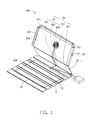
- FIG. 1 is a schematic view of a holder, according to an embodiment.
- FIG. 2 is a schematic view of the holder of FIG. 1 holding different portable electronic devices.
- FIG. 3 is a circuit block diagram of the holder of FIG. 2 .
- FIG. 1 shows a holder 100 used for receiving a first portable electronic device 60 and a second portable electronic device 70 .
- the first portable electronic device 60 is a tablet computer
- the second portable electronic device 70 is a mobile phone, but the disclosure is not limited thereto.
- the holder 100 includes a cover 10 , a base 30 , and a charging module 50 .
- the base 30 receives the tablet computer 60 and the mobile phone 70 .
- the cover 10 is foldable relative to the base 30 to cover the tablet computer 60 .
- the charging module 50 charges the tablet computer 60 and the mobile phone 70 .
- the cover 10 defines a plurality of grooves 102 substantially parallel to each other to position the tablet computer 70 received in the base 30 at different angles relative to the cover 10 .
- a battery 11 is received in the cover 10 and has a holder port 13 exposed from the cover 10 . The battery 11 charges the tablet computer 60 and the mobile phone 70 through the holder port 13 .
- the base 30 includes a main plate 31 and a support plate 35 foldable relative to the main plate 31 .
- One surface of the main plate 31 has two first latching walls 312 at opposite sides of the main plate 31 , respectively, and a second latching wall 314 between the two first latching walls 312 .
- the first latching walls 312 and the second latching wall 314 cooperatively define a first receiving space 310 on a first surface of the main plate 31 .
- the first receiving space 310 receives one part of the tablet computer 60 .
- One of the first latching walls 312 defines a through hole 37 .
- Another surface of the main plate 31 has a receiving portion 33 .
- a size of the receiving portion 33 corresponds to a size of the mobile phone 70 .
- a second receiving space 331 is defined in the receiving portion 33 for receiving the mobile phone 70 .
- Opposite sides of the support plate 35 are foldably connected to the main plate 31 and the cover 10 , respectively.
- the tablet computer 60 needs to be supported at an angle relative to the cover 10 , one part of the tablet computer 60 is received in the first receiving space 310 , while the other part of the tablet computer 60 is received in one of the grooves 102 .
- the support plate 35 is angled relative to the main plate 31 and the cover 10 for holding the tablet computer 60 .
- the tablet computer 60 has a first port 61 and a second port 63 .
- the mobile phone 70 has a third port 71 .
- the through hole 37 is aligned with the first port 61 , so that the first port 61 of the tablet computer 60 is exposed from the holder 100 .
- a first wire 15 electrically connects the holder port 13 of the battery 11 to the second port 63 to charge the tablet computer 60 .
- a second wire 17 electrically connects the first port 61 to the third port 71 to transmit the energy of the tablet computer 60 to the mobile phone 70 .
- the charging module 50 includes an arraying cable 51 , a main charging coil 53 , and a power supply 55 .
- the arraying cable 51 electrically connects the charging coil 53 and the battery 11 to the power supply 55 .
- the arraying cable 51 has a first arraying cable 511 , a second arraying cable 513 , and a third arraying cable 515 .
- the first arraying cable 511 is connected to the third arraying cable 515 for electrically connecting the main charging coil 53 to the power supply 55 .
- the second arraying cable 513 is connected to the third arraying cable 515 for electrically connecting the battery 11 to the power supply 55 .
- the tablet computer 60 has a first secondary charging coil 65
- the mobile phone 70 has a second secondary charging coil 75 .
- the power supply 55 When the power supply 55 is provided, one first proportion of a current from the power supply 55 is sent to the main charging coil 53 , and the current from the main charging coil 53 is coupled to the first secondary charging coil 65 and the second secondary charging coil 75 by electromagnetic coupling for charging the tablet computer 60 and the mobile phone 70 , respectively.
- a second proportion of the current from the power supply 55 charges the battery 11 .
- the tablet computer 60 and the mobile phone 70 are charged by the battery 11 via the first wire 15 and the second wire 17 , respectively.
Abstract
Description
Claims (5)
Applications Claiming Priority (2)
| Application Number | Priority Date | Filing Date | Title |
|---|---|---|---|
| CN2013101702100 | 2013-05-10 | ||
| CN201310170210.0A CN104142710A (en) | 2013-05-10 | 2013-05-10 | Tablet computer protection case and tablet computer protection system applying same |
Publications (2)
| Publication Number | Publication Date |
|---|---|
| US20140333255A1 US20140333255A1 (en) | 2014-11-13 |
| US9577451B2 true US9577451B2 (en) | 2017-02-21 |
Family
ID=51851912
Family Applications (1)
| Application Number | Title | Priority Date | Filing Date |
|---|---|---|---|
| US14/040,491 Expired - Fee Related US9577451B2 (en) | 2013-05-10 | 2013-09-27 | Holder for portable electronic device |
Country Status (4)
| Country | Link |
|---|---|
| US (1) | US9577451B2 (en) |
| JP (1) | JP2014220994A (en) |
| CN (1) | CN104142710A (en) |
| TW (1) | TW201442663A (en) |
Families Citing this family (9)
| Publication number | Priority date | Publication date | Assignee | Title |
|---|---|---|---|---|
| US9160183B2 (en) * | 2012-06-27 | 2015-10-13 | Bren-Tronics, Inc. | Foldable battery charger |
| CN106155187B (en) * | 2015-04-08 | 2020-01-31 | 群光电子股份有限公司 | Portable electronic device and protective cover thereof |
| US20160380454A1 (en) * | 2015-06-25 | 2016-12-29 | Intel Corporation | Wireless charging sleeve for electronic devices |
| DE112015007135T5 (en) * | 2015-11-19 | 2018-08-02 | Intel Corporation | Pivoting wireless charging systems and methods |
| KR101884753B1 (en) * | 2017-12-29 | 2018-08-02 | 애드크런치 주식회사 | Application for managing charging circuit and system using the same |
| WO2020145933A1 (en) * | 2019-01-07 | 2020-07-16 | Coleman Johnathan | Power screen protector |
| US10784696B1 (en) * | 2019-02-11 | 2020-09-22 | Alfi, Inc. | Methods and apparatus for a tablet computer system incorporating a battery charging station |
| US10910854B2 (en) | 2019-02-11 | 2021-02-02 | Alfi, Inc. | Methods and apparatus for a tablet computer system incorporating a battery charging station |
| US11909248B2 (en) * | 2020-06-04 | 2024-02-20 | Apple Inc. | Accessory with a magnetic relay structure for wireless power transfer |
Citations (10)
| Publication number | Priority date | Publication date | Assignee | Title |
|---|---|---|---|---|
| US6046571A (en) * | 1998-08-21 | 2000-04-04 | Digital Equip Corp | Port replicator with secure integral battery charging cradle |
| US6193546B1 (en) * | 1999-03-16 | 2001-02-27 | Ericsson Inc. | Support assembly for personal electronic device and method for using the same |
| US20050189913A1 (en) * | 2004-02-26 | 2005-09-01 | Vitanov Kamen B. | Electronic device including handheld electronic device with dual battery configuration, and associated method |
| US20080106232A1 (en) * | 2006-11-03 | 2008-05-08 | Research In Motion Limited | Electronic device, including handheld electronic device, with dual battery configuration and associated method |
| US7612997B1 (en) * | 2008-11-17 | 2009-11-03 | Incase Designs Corp. | Portable electronic device case with battery |
| US20090284216A1 (en) * | 2008-05-09 | 2009-11-19 | Ipowerup, Inc. | Portable and universal hybrid-charging apparatus for portable electronic devices |
| US20130063873A1 (en) * | 2011-09-12 | 2013-03-14 | Apple Inc. | Integrated inductive charging in protective cover |
| US20130278207A1 (en) * | 2012-04-20 | 2013-10-24 | Samsung Electronics Co. Ltd. | Wired/wireless charging apparatus and circuit |
| US8698454B2 (en) * | 2011-04-02 | 2014-04-15 | Hon Hai Precision Industry Co., Ltd. | Charging appraratus for portable electronic device |
| US20140253024A1 (en) * | 2013-03-06 | 2014-09-11 | Nokia Corporation | Method and apparatus for wirelessly charging mobile devices |
-
2013
- 2013-05-10 CN CN201310170210.0A patent/CN104142710A/en active Pending
- 2013-05-15 TW TW102117178A patent/TW201442663A/en unknown
- 2013-09-27 US US14/040,491 patent/US9577451B2/en not_active Expired - Fee Related
-
2014
- 2014-04-28 JP JP2014092378A patent/JP2014220994A/en active Pending
Patent Citations (10)
| Publication number | Priority date | Publication date | Assignee | Title |
|---|---|---|---|---|
| US6046571A (en) * | 1998-08-21 | 2000-04-04 | Digital Equip Corp | Port replicator with secure integral battery charging cradle |
| US6193546B1 (en) * | 1999-03-16 | 2001-02-27 | Ericsson Inc. | Support assembly for personal electronic device and method for using the same |
| US20050189913A1 (en) * | 2004-02-26 | 2005-09-01 | Vitanov Kamen B. | Electronic device including handheld electronic device with dual battery configuration, and associated method |
| US20080106232A1 (en) * | 2006-11-03 | 2008-05-08 | Research In Motion Limited | Electronic device, including handheld electronic device, with dual battery configuration and associated method |
| US20090284216A1 (en) * | 2008-05-09 | 2009-11-19 | Ipowerup, Inc. | Portable and universal hybrid-charging apparatus for portable electronic devices |
| US7612997B1 (en) * | 2008-11-17 | 2009-11-03 | Incase Designs Corp. | Portable electronic device case with battery |
| US8698454B2 (en) * | 2011-04-02 | 2014-04-15 | Hon Hai Precision Industry Co., Ltd. | Charging appraratus for portable electronic device |
| US20130063873A1 (en) * | 2011-09-12 | 2013-03-14 | Apple Inc. | Integrated inductive charging in protective cover |
| US20130278207A1 (en) * | 2012-04-20 | 2013-10-24 | Samsung Electronics Co. Ltd. | Wired/wireless charging apparatus and circuit |
| US20140253024A1 (en) * | 2013-03-06 | 2014-09-11 | Nokia Corporation | Method and apparatus for wirelessly charging mobile devices |
Also Published As
| Publication number | Publication date |
|---|---|
| JP2014220994A (en) | 2014-11-20 |
| TW201442663A (en) | 2014-11-16 |
| CN104142710A (en) | 2014-11-12 |
| US20140333255A1 (en) | 2014-11-13 |
Similar Documents
| Publication | Publication Date | Title |
|---|---|---|
| US9577451B2 (en) | Holder for portable electronic device | |
| US20160105047A1 (en) | Mobile device mounting and charging system | |
| US20140197784A1 (en) | Wireless side charging | |
| US20110241607A1 (en) | Electronic device with integral inductive charging station | |
| US9462242B2 (en) | Smartphone and external micro projector thereof | |
| CN107863800B (en) | Wireless rechargeable battery | |
| KR101571530B1 (en) | Multi purpose charging cradle | |
| US20150002085A1 (en) | Fixing apparatus with wireless charging | |
| US9857846B2 (en) | Portable computing device cover including a keyboard | |
| US20130207472A1 (en) | Extension USB Socket | |
| US20160020626A1 (en) | Wireless charging device | |
| US9197087B2 (en) | Portable charger with rotatable locking portions | |
| US20170346321A1 (en) | Disposable Charger for a Mobile Electronic Device | |
| US20170163063A1 (en) | Portable phone charger with auxiliary functions | |
| CN203225555U (en) | Protection device of electronic device | |
| US10429886B2 (en) | Assembly and housing for terminal device | |
| US20150015189A1 (en) | Portable power source providing support by notch | |
| US9379562B2 (en) | Holding assembly for portable electronic device | |
| US20180175654A1 (en) | Portable Speaker Charging Structure | |
| US20160261138A1 (en) | Wireless charging receiver | |
| US9325199B2 (en) | Wireless charging device | |
| JP3208292U (en) | Charging mobile devices using sunlight | |
| KR20160102678A (en) | Portable Multi-Function Rechargeable Battery Pack | |
| TW201306436A (en) | Solar cell phone charging apparatus | |
| CN101115084A (en) | Slave unit for a portable communication terminal |
Legal Events
| Date | Code | Title | Description |
|---|---|---|---|
| AS | Assignment |
Owner name: FIH (HONG KONG) LIMITED, HONG KONG Free format text: ASSIGNMENT OF ASSIGNORS INTEREST;ASSIGNORS:HAN, DONG;CHANG, CHIH-WEI;REEL/FRAME:031303/0573 Effective date: 20130923 Owner name: SHENZHEN FUTAIHONG PRECISION INDUSTRY CO., LTD., C Free format text: ASSIGNMENT OF ASSIGNORS INTEREST;ASSIGNORS:HAN, DONG;CHANG, CHIH-WEI;REEL/FRAME:031303/0573 Effective date: 20130923 |
|
| STCF | Information on status: patent grant |
Free format text: PATENTED CASE |
|
| FEPP | Fee payment procedure |
Free format text: MAINTENANCE FEE REMINDER MAILED (ORIGINAL EVENT CODE: REM.); ENTITY STATUS OF PATENT OWNER: LARGE ENTITY |
|
| LAPS | Lapse for failure to pay maintenance fees |
Free format text: PATENT EXPIRED FOR FAILURE TO PAY MAINTENANCE FEES (ORIGINAL EVENT CODE: EXP.); ENTITY STATUS OF PATENT OWNER: LARGE ENTITY |
|
| STCH | Information on status: patent discontinuation |
Free format text: PATENT EXPIRED DUE TO NONPAYMENT OF MAINTENANCE FEES UNDER 37 CFR 1.362 |
|
| FP | Lapsed due to failure to pay maintenance fee |
Effective date: 20210221 |