US9582272B1 - Method and system for remote computing session management - Google Patents
Method and system for remote computing session management Download PDFInfo
- Publication number
- US9582272B1 US9582272B1 US13/523,407 US201213523407A US9582272B1 US 9582272 B1 US9582272 B1 US 9582272B1 US 201213523407 A US201213523407 A US 201213523407A US 9582272 B1 US9582272 B1 US 9582272B1
- Authority
- US
- United States
- Prior art keywords
- encoder
- processor
- session
- image
- image portion
- Prior art date
- Legal status (The legal status is an assumption and is not a legal conclusion. Google has not performed a legal analysis and makes no representation as to the accuracy of the status listed.)
- Active, expires
Links
Images


Classifications
-
- G—PHYSICS
- G06—COMPUTING; CALCULATING OR COUNTING
- G06F—ELECTRIC DIGITAL DATA PROCESSING
- G06F9/00—Arrangements for program control, e.g. control units
-
- G—PHYSICS
- G06—COMPUTING; CALCULATING OR COUNTING
- G06F—ELECTRIC DIGITAL DATA PROCESSING
- G06F9/00—Arrangements for program control, e.g. control units
- G06F9/06—Arrangements for program control, e.g. control units using stored programs, i.e. using an internal store of processing equipment to receive or retain programs
- G06F9/46—Multiprogramming arrangements
- G06F9/50—Allocation of resources, e.g. of the central processing unit [CPU]
- G06F9/5005—Allocation of resources, e.g. of the central processing unit [CPU] to service a request
- G06F9/5027—Allocation of resources, e.g. of the central processing unit [CPU] to service a request the resource being a machine, e.g. CPUs, Servers, Terminals
- G06F9/5044—Allocation of resources, e.g. of the central processing unit [CPU] to service a request the resource being a machine, e.g. CPUs, Servers, Terminals considering hardware capabilities
-
- G—PHYSICS
- G06—COMPUTING; CALCULATING OR COUNTING
- G06F—ELECTRIC DIGITAL DATA PROCESSING
- G06F9/00—Arrangements for program control, e.g. control units
- G06F9/06—Arrangements for program control, e.g. control units using stored programs, i.e. using an internal store of processing equipment to receive or retain programs
- G06F9/44—Arrangements for executing specific programs
- G06F9/455—Emulation; Interpretation; Software simulation, e.g. virtualisation or emulation of application or operating system execution engines
- G06F9/45533—Hypervisors; Virtual machine monitors
- G06F9/45558—Hypervisor-specific management and integration aspects
- G06F2009/4557—Distribution of virtual machine instances; Migration and load balancing
-
- G—PHYSICS
- G06—COMPUTING; CALCULATING OR COUNTING
- G06F—ELECTRIC DIGITAL DATA PROCESSING
- G06F2209/00—Indexing scheme relating to G06F9/00
- G06F2209/50—Indexing scheme relating to G06F9/50
- G06F2209/503—Resource availability
-
- G—PHYSICS
- G06—COMPUTING; CALCULATING OR COUNTING
- G06F—ELECTRIC DIGITAL DATA PROCESSING
- G06F2209/00—Indexing scheme relating to G06F9/00
- G06F2209/50—Indexing scheme relating to G06F9/50
- G06F2209/509—Offload
-
- G—PHYSICS
- G06—COMPUTING; CALCULATING OR COUNTING
- G06F—ELECTRIC DIGITAL DATA PROCESSING
- G06F3/00—Input arrangements for transferring data to be processed into a form capable of being handled by the computer; Output arrangements for transferring data from processing unit to output unit, e.g. interface arrangements
- G06F3/14—Digital output to display device ; Cooperation and interconnection of the display device with other functional units
- G06F3/1423—Digital output to display device ; Cooperation and interconnection of the display device with other functional units controlling a plurality of local displays, e.g. CRT and flat panel display
- G06F3/1438—Digital output to display device ; Cooperation and interconnection of the display device with other functional units controlling a plurality of local displays, e.g. CRT and flat panel display using more than one graphics controller
-
- G06F9/4445—
-
- G—PHYSICS
- G06—COMPUTING; CALCULATING OR COUNTING
- G06F—ELECTRIC DIGITAL DATA PROCESSING
- G06F9/00—Arrangements for program control, e.g. control units
- G06F9/06—Arrangements for program control, e.g. control units using stored programs, i.e. using an internal store of processing equipment to receive or retain programs
- G06F9/44—Arrangements for executing specific programs
- G06F9/451—Execution arrangements for user interfaces
- G06F9/452—Remote windowing, e.g. X-Window System, desktop virtualisation
Definitions
- Embodiments of the present invention generally relate to remote computing, and, more specifically, to user interface session management in a multi-session computing environment.
- VDI Virtual Desktop Infrastructure
- a high performance computer such as a server
- VM virtual machines
- Remote computers such as thin clients, zero clients, or mobile devices, each establish a connection with a particular VM, typically designated by a connection broker in communication with both the server and remote computing devices.
- the user experience associated with a remote computing session between a VM and a remote computer becomes subject to performance degradation (i.e., increased latency, poor video quality, and/or dysfunctional peripheral devices) in various situations where the server becomes overloaded or the VM is migrated to a different server for administrative reasons, such as scheduled maintenance or load balancing measures.
- performance degradation i.e., increased latency, poor video quality, and/or dysfunctional peripheral devices
- Embodiments of the present invention generally relate to a method and apparatus for image encoding.
- the method comprises encoding a first image portion by a first encoder associated with a first processor at a host system; dynamically determining a requirement to encode a second image portion by the first encoder or by a second encoder associated with a second processor at the host system; and encoding, based on the requirement, the second image portion by the first encoder or the second encoder.
- FIG. 1 is a block diagram of system comprising a remote computing environment in accordance with one or more embodiments of the present invention
- FIG. 2 a block diagram a illustrating a protocol structure in accordance with one or more embodiments of the present invention
- FIG. 3 is a block diagram illustrating a protocol stack in accordance with one or more embodiments of the present invention.
- FIGS. 4A and 4B illustrate the peer-to-peer relationship between corresponding layers of a slow path stack (SPS) and a fast path stack (FPS) in accordance with one or more embodiments of the present invention
- FIG. 5 illustrates three general phases of a network session management method in accordance with one or more embodiments of the present invention
- FIG. 6 illustrates an embodiment of a method for transitioning a processing function between a virtual machine (VM) and a User Interface (UI) session processor at a host computer;
- VM virtual machine
- UI User Interface
- FIG. 7 illustrates an embodiment of a method for migrating a remote computing session, the remote computing session using at least one codec function of a UI session processor, from one host computer to another;
- FIG. 8 illustrates a method for transitioning a remote computing session from one VM to another VM in accordance with one or more embodiments of the present invention
- FIG. 9 illustrates select details of a host computer enabled for dynamic transition between software and hardware offload image encoders in accordance with one or more embodiments of the present invention
- FIG. 10 is a block diagram illustrating communication structures within a memory of a host processor in accordance with one or more embodiments of the present invention.
- FIG. 11 illustrates a method for switching or distributing image compression between image encoding resources of a VM and image encoding resources of a UI session processor in accordance with one or more embodiments of the present invention.
- the present invention discloses a system and method for managing a remote computing session between a remote computer and a VM during migration of processing functions (e.g., codec functions) between the VM and a User Interface (UI) session processor.
- processing functions e.g., codec functions
- UI User Interface
- a remote computer establishes a remote computing session with a VM operating on a particular host computer. If the VM has access to processing functions, such as image, Universal Serial Bus (USB), and/or audio coding functions advertised by a local UI session processor, the remote computing session is configured to include select advertised processing functions of the UI session processor rather than engaging similar functions provided by software in the VM itself. In some embodiments, such processing functions are migrated between the VM and the UI session processor within the context of an uninterrupted remote computing session to meet the dynamic processing distribution demands of the system.
- processing functions such as image, Universal Serial Bus (USB), and/or audio coding functions advertised by a local UI session processor
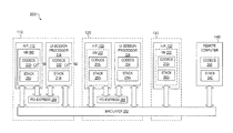
- FIG. 1 is a block diagram of system 100 comprising a remote computing environment in accordance with one or more embodiments of the present invention.
- the system 100 comprises a first host computer 110 which, in itself, may comprise several host processors 112 (depicted as host processor 112 1 . . . 112 K ), and at least one UI session processor 114 coupled to network 150 by Internet Protocol (IP) connection 172 .
- each host processor 112 comprises at least one Central Processing Unit (CPU), optionally one or more Graphic Processing Units (GPUs), or a combination of CPU and GPU processing elements, as well as additional elements for coupling host memory, CPU resources, and bus infrastructure, such as north bridge, south bridge, bus controller, and memory controller elements.
- CPU Central Processing Unit
- GPUs Graphic Processing Units
- additional elements for coupling host memory, CPU resources, and bus infrastructure, such as north bridge, south bridge, bus controller, and memory controller elements.
- host processor 112 comprises one or more multi-core CPUs or separate CPUs interconnected by a HYPERTRANSPORT fabric, INTEL QUICKPATH interconnect, or the like, with host memory distributed between CPUs accordingly.
- suitable CPUs include server class processors (such as 32-bit, 64-bit, or other CPUs, including OPTERON or ATHLON class microprocessors manufactured by AMD Corporation), XEON or PENTIUM class processors manufactured by INTEL, or SPARC microprocessors manufactured by SUN MICROSYSTEMS Inc.
- server class processors such as 32-bit, 64-bit, or other CPUs, including OPTERON or ATHLON class microprocessors manufactured by AMD Corporation
- XEON or PENTIUM class processors manufactured by INTEL or SPARC microprocessors manufactured by SUN MICROSYSTEMS Inc.
- any other microprocessor platform designed to host the remote computing methods described herein may be utilized.
- the host processors 112 host a virtualized desktop infrastructure (VDI) generally comprising a plurality of VMs (including VM 160 and other VMs not shown in FIG. 1 ) stored in host memory.
- VDI virtualized desktop infrastructure
- Each VM generally comprises an operating system, driver software, and application software associated with a remote computing session.
- software applications with display presentation requirements e.g., graphics drivers executing in conjunction with computer-aided design (CAD) software, spreadsheets, word processing software, and the like
- CAD computer-aided design
- Each initial display image is compressed by either software encoding resources in the VM or UI session processor 114 , followed by communication of the compressed display image to a remote computer.
- UI session processor 114 Thereafter, changes to each display image are tracked, typically using frame buffer monitoring structures (i.e. one or more dirty mask bitmaps) and image updates associated with the display image changes are compressed by one of software encoding resources or UI session processor 114 and communicated.
- the host processors 112 are coupled to the UI session processor 114 by a peripheral interconnect, such as a PCI-EXPRESS interconnect supported by bus switch 118 comprising at least one of a server root complex manufactured by semiconductor vendors such as INTEL or AMD Corporations, or a PCI-EXPRESS switch manufactured by vendors such as PLX TECHNOLOGIES or INTEGRATED DEVICE TECHNOLOGIES (IDT).
- a peripheral interconnect such as a PCI-EXPRESS interconnect supported by bus switch 118 comprising at least one of a server root complex manufactured by semiconductor vendors such as INTEL or AMD Corporations, or a PCI-EXPRESS switch manufactured by vendors such as PLX TECHNOLOGIES or
- the host processors 112 are also coupled to network 150 by IP connection 170 supported by network switch 116 .
- host computer 110 is a blade or rack-mount server system with host processors 112 comprising pluggable blades or modules supported by network switch 116 .
- network switch 116 may comprise hardware-based switching apparatus from companies such as BROADCOM, MARVEL, or CISCO corporations, and/or virtualized software-based switching components, such as a NEXUS vSwitch from CISCO corporation.
- network switch 116 , bus switch 118 , and UI session processor 114 are pluggable, backplane-assembled, or independently-mounted apparatus in different embodiments.
- host computer 110 may take forms other than a blade server, such as a plurality of independent computers coupled by cables or a plurality of processing cores and connection logic co-located on one or more silicon die structures.
- System 100 comprises a second host computer 120 with host processors 122 (depicted as host processor 122 1 . . . 122 L ) and UI session processor 124 , and having IP connections 174 and 176 , aided by network switch 126 and bus switch 128 , respectively, to network 150 .
- system 100 comprises host computers 130 and 180 .
- Host computer 130 comprises host processors 132 (depicted as host processor 132 1 . . . 132 M ), and has an IP connection 178 , aided by network switch 136 to the network 150 .
- Host computer 180 comprises host processors 182 (depicted as host processor 182 1 . . .
- Host computers 130 and 180 lack the UI session processors of host computers 110 and 120 , as may be the case for generic off-the-shelf-server products. However, host computers 130 and 180 are nevertheless each enabled to host software services essential for providing remote computing sessions.
- system 100 may comprise fewer or more host computers of the same type as host computers 110 and 120 (i.e., host computers comprising several host processors and at least one UI session processor), fewer or more host computers of the same type as host computers 130 and 180 (i.e., host computers comprising several host processors and lacking a UI session processor), or any combination of the foregoing.
- the host computers 110 , 120 , 130 , and 180 are servers (i.e., system 100 comprises a first set of servers comprising UI session processor resources and a second set of servers without such UI session processor resources).
- the network 150 comprises a communication system (e.g., the Internet, LAN, Wide Area Network (WAN), and the like) that connects computer systems completely by wire, cable, fiber optic, and/or wireless links facilitated by various types of well-known network elements, such as connection broker 152 , Network Address Translation (NAT) gateways, hubs, switches, routers, firewalls, and the like.
- the network 150 may employ various well-known protocols, such as security protocols, to communicate information amongst the network resources.
- network 150 is a corporate network including part of the Internet.
- the remote computers 140 are, generally, computing devices enabled to provide remote computing functions, such as presenting a computer desktop image (i.e., image data) for display (i.e., a display image), providing ports for connecting peripheral devices, and a providing network interfaces for connection to network 150 .
- remote computer 140 is a terminal in a networked remote computer system 100 . Examples of such remote terminals include zero client computers, thin client computers, personal computers, notebook computers, workstations, Personal Digital Assistants (PDAs), wireless devices, and the like.
- PDAs Personal Digital Assistants
- Remote computer 140 comprises various session management and processing resources for encoding or decoding media, including image data and peripheral device data, associated with a remote computing session.
- remote computer 140 comprises at least one of an image decoder for decoding compressed display image data received from the host computer, an audio decoder for decompressing output audio data, and an audio encoder for compressing input audio data.
- remote computer 140 may comprise a USB codec for managing the translation of USB data between format requirements of one or more underlying USB bus controllers and format requirements suitable for standard network communication, such as USB Request Block (URB) format used in USB-over-IP protocols known to the art.
- UMB USB Request Block
- the remote computer 140 is coupled to User Interface (UI) sub-system 142 , (depicted as UI sub-systems 142 1 . . . 142 P ), typically including UI devices, such as display, mouse, keyboard, audio devices, and/or other devices such as biometric peripherals, webcam, printers, and the like. Such devices are generally coupled to remote computer 140 by industry compliant connections, such as USB, DisplayPort, Digital Visual Interface (DVI), and the like.
- the remote computer 140 comprises software stack components and session management functions, described herein, used for the establishment of a remote computing session with an available host computer (i.e., host computer 110 , 120 , 130 , or 180 ).
- One of the remote computers 140 establishes a connection with a virtual machine 160 (executed by a host processor 112 ) under direction of a connection broker 152 on network 150 .
- the remote computing session between VM 160 and the remote computer 140 is aided by various codec functions resident within VM 160 and/or within UI session processor 114 .
- a particular codec function e.g., an image compression function
- the termination endpoint at UI session processor 114 (and related network connection 172 to network 150 ) of a remote computing session between VM 160 and remote computer 140 is migrated from UI session processor 114 to VM 160 (and related network connection 170 ) without service interruption.
- a migration may be performed in preparation for a live migration of VM 160 (and the remote computing session) to host computer 120 (ref. VM migration path 162 ) or a live migration of VM 160 to host computer 130 (ref. VM migration path 164 ) or host computer 180 using VM migration methods known to the art.
- the VM 160 may also be migrated to a different host processor 112 of host computer 110 , either by retaining the network session endpoint at UI session processor 114 and utilizing a different connection on switch 118 , or by first moving the network session endpoint from UI session processor 114 to VM 160 followed by using a different connection on network switch 116 directed to the different host processor 112 hosting the relocated VM.
- system 100 comprises multiple remote computers, each enabled to establish a remote computing session with an available VM and each host processor typically configured to execute many separate VMs.
- a host processor such as host processor 112
- hypervisor software 190 also referred to as “hypervisor 190 ” or “hypervisor domain 190 ”
- hypervisor software 190 examples include ESX from VMWARE Corporation, XEN from CITRIX corporation, or HYPER-V from MICROSOFT corporation.
- the hypervisor software 190 comprises a “type II” hypervisor, such as a LINUX operating system available from various vendors (e.g., ‘GSX Server’ from VMWARE, ‘Virtual PC’ from MICROSOFT, or ‘VIRTUALBOX’ from SUN MICROSYSTEMS), which incorporates various software applications that manage the execution of the separate VMs.
- host processor 112 comprises one or more remote computing applications, such one or more terminal server applications. Such remote computing applications execute either inside VM 160 under management of hypervisor 190 or directly in an operating system environment of host processor 112 in the absence of hypervisor 190 or independent of hypervisor 190 .
- FIG. 2 is a block diagram a illustrating a protocol structure 200 in accordance with one or more embodiments of the present invention.
- the protocol structure 200 enables the remote computer 140 of to engage in a remote computing session with host computer 110 (comprising VM and UI session processor components) or a remote computing session that has been migrated to computer 120 or to computer 130 .
- VM 160 is coupled to remote computer 140 by underlying data link structure Media Access Controller (MAC) layer 252 , supported by protocol stack 250 1 in the VM 160 and complementary stack 242 in the remote computer 140 .
- MAC Media Access Controller
- the host processor 112 of VM 160 is coupled to UI session processor 114 by PCI-EXPRESS interconnect 254 , supported by bus switch 118 , physical layer structures, data-link protocol, and transaction layer protocol not shown in FIG. 2 .
- host computer 120 comprises PCI-EXPRESS interconnect 256 coupling one or more host processors 122 to UI session processor 124 .
- VM 160 comprises a suite of codecs 210 1 , including codec 180 .
- the codecs 210 1 comprise machine executable instructions directed at one or more media processing functions for encoding or decoding media associated with a remote computing session.
- media processing functions include audio compression for egress audio channels, audio decompression for ingress audio channels, other audio or voice processing functions, USB data coding or decoding functions, video decoder functions (e.g., enabled to decode an ingress video stream from a webcam), file compression functions, or image encoding functions.
- the suite of codecs 210 1 of VM 160 are supported by codecs 240 in the remote computer 140 .
- the codecs 240 provide complementary media processing functions, such as audio decompression for egress audio channels, audio compression for ingress audio channels, other audio or voice processing functions, USB data coding or decoding functions, video encoder functions (e.g., enabled to encode an ingress video stream from a webcam), file decompression functions, or image decoding functions.
- Stack 250 1 provides a network session termination point for various communications between remote computer 140 and VM 160 , including media plane communications (e.g., peripheral device data and compressed image data) and control plane communications, such as session establishment, exchange of security information, tear down communications, and the like.
- media plane communications e.g., peripheral device data and compressed image data
- control plane communications such as session establishment, exchange of security information, tear down communications, and the like.
- one or more lower layers of stack 250 1 such as IP addressing functions, are implemented outside the domain of VM 160 , e.g., in the hypervisor 190 or network switch 116 .
- UI Session processor 114 comprises codecs 212 (including codec 182 ) and protocol stack 214 1 which provides protocol functions generally equivalent to those of stack 250 1 when processor 114 serves as the network session endpoint with remote computer 140 .
- VM 160 is instantiated as VM 222 with codecs 210 2 and stack 250 2 following a live migration of the VM 160 from host computer 110 to host computer 120 . It will be apparent to those of skill in the art of software engineering that codecs 210 2 and stack 250 2 are essentially replicas of codecs 210 1 and stack 250 1 .
- UI Session processor 124 comprises codecs 224 (which may offer a different set of coded functions than those of codecs 212 ) and protocol stack 214 2 .
- Protocol stack 214 2 provides protocol functions generally equivalent to those of stack 250 2 under circumstances in which UI session processor 124 serves as the network session endpoint.
- VM 160 is instantiated as VM 232 with codecs 210 3 and stack 250 3 after a migration from computer 110 to computer 130 .
- FIG. 3 is a block diagram illustrating a protocol stack 300 in accordance with one or more embodiments of the present invention.
- Protocol stack 300 is a communication stack, suited to both host computer and remote computer implementations, for managing control and media aspects of a remote computing session (i.e., stack 300 may be implemented as stack 250 , 214 or 242 ).
- host computer and remote computer implementations i.e., stack 250 , 214 , and stack 242
- SSO single sign-on
- the host computer implementation of stack 300 may comprise a hypervisor interface 340 between VM 160 and management software in hypervisor 190 tasked with VM provisioning and policy functions. Additionally, host computer and UI session processor implementations of stack 300 may comprise PCI-EXPRESS interface 350 to support communications between them.
- control path between host computer and remote computer implementations of stack 300 comprises slow path stack (SPS) 310 , utilized for session signaling.
- the control path further comprises fast path stack (FPS) 320 , utilized for control of the media plane which comprises various virtual channels of compressed image data and peripheral device data.
- SPS 310 and FPS 320 are each executed at both the host computer 110 , 120 , and 130 , and the remote computer 140 .
- Each stack 310 and 320 is layered, for example, according to the Open Systems Interconnect (OSI) reference model in which each layer encapsulates the packet passed down by a higher layer.
- OSI Open Systems Interconnect
- SPS 310 comprises session signaling (SSIG) layer 312 and secure channel (SCHAN) layer 314 , underpinned by a reliable Transmission Control Protocol/Internet Protocol (TCP/IP) layer 316 .
- Slow path traffic generally comprises infrequent signaling that is tolerant to scheduling delays, usually set to a lower communication priority than media plane or FPS-related communications.
- SSIG layer 312 is invoked during session startup and teardown. During session startup, SSIG layer 312 performs a startup handshake involving initial peer contact, peer authentication and negotiation of session parameters (such as encryption keys for FPS 320 ) with a peer SSIG layer at the other end of the network.
- a protocol comparable to Session Initiation Protocol is used by SSIG layer 312 to negotiate media capabilities (e.g., encoder attributes and peripheral device data types) and fast path communication parameters (e.g., encryption keys, security, and the like) using an INVITE handshake and exchange of Application Protocol Data Units (APDU) in conjunction with a Session Description Protocol (SDP), for example a protocol similar to SDP of RFC 4566 and RFC 3264.
- SDP Session Description Protocol
- the SDP defines the session parameters exchanged by the SSIG layer 312 at host and remote computers.
- the remote computer 140 provides its SDP parameters (SDP offer) in the ‘INVITE’ APDU, and the server provides parameters (SDP answer) in the ‘INVITE_OK’ APDU.
- the SDP answer may include negotiated fast-path and media parameters to be used for the remote computing session.
- the SDP generally comprises of a mix of negotiable and non-negotiable parameters.
- the remote computer 140 communicates a set of non-negotiable parameters (e.g., data plane connection IP address and port number(s)) and negotiable parameters (e.g., peripheral device data type and/or encoder attributes) to the peer stack of the host computer (e.g., stacks 250 or 214 ).
- the host stack uses the received negotiable parameters to negotiate local settings for the host computer, following which a combination of negotiated parameters and the host stack's non-negotiable parameters (e.g., data plane connection IP address and port number(s)) are communicated back to the remote computer 140 in the subsequent SDP answer.
- the remote computer 140 uses the negotiated parameters sent by the peer stack of the host computer for the session.
- the SDP supports negotiation of parameters for User Interface Protocol (UIP) 328 , such as data packet encapsulation preferences (e.g., UDP selection), link rate negotiation (e.g., 10 Mbps vs. 100 Mbps), Maximum Transmission Unit (MTU) size negotiation, encryption parameters, and attributes of peripheral device data virtual channels.
- UDP User Interface Protocol
- link rate negotiation e.g., 10 Mbps vs. 100 Mbps
- MTU Maximum Transmission Unit
- encryption parameters e.g., encryption parameters, and attributes of peripheral device data virtual channels.
- attributes include peripheral data channel enablement switches for USB, audio, image, generic I/O, and Display Data Channel (DDC) data types, and peripheral data attributes, such as encoding method, audio format (e.g., specific Adaptive Differential Pulse Code Modulation (ADPCM) format), and the like.
- ADPCM Adaptive Differential Pulse Code Modulation
- the SSIG layer 312 maintains a TCP connection with the peer and monitors end-to-end network connection integrity using a client-server keep alive mechanism.
- the SSIG layer 312 also tears down the remote computing session using a ‘BYE’ handshake, initiated either by the remote computer 140 or the current host computer (e.g., host computer 110 ).
- the secure channel SCHAN layer 314 provides a datagram-like service to higher entities and abstracts lower layer TCP or UDP oriented transport mechanics by accepting APDUs from the higher layer modules, generating packets, and transporting the data over an encrypted TCP socket (e.g., Transport Layer Security (TLS) Secure Socket Layer (SSL)) to the peer SCHAN layer which delivers APDUs to the higher layer modules at the peer.
- TCP socket e.g., Transport Layer Security (TLS) Secure Socket Layer (SSL)
- the FPS stack 320 is generally a lightweight protocol tailored for rapid processing of frequent real-time communications data, consequently commanding a higher queuing and scheduling priority compared to traffic associated with SPS 310 .
- the UIP layer 328 provides reliable and unreliable transport channels for media control information and data, including encryption and transport layer services for image data, peripheral device data, and control channels.
- the Simple Communications Protocol (SCP) layer 326 provides a connection oriented datagram-like service for setting up a peer-to-peer channel (using an ‘INVITE’ handshake) and packetizing user data for transport.
- SCP Simple Communications Protocol
- SCP layer 326 implements a retransmit mechanism during the initial connection handshake and, when reliable transport is available, SCP layer 326 uses the provided transport mechanism to guarantee delivery of handshake-related packets to the SCP peer.
- SCP layer 326 provides Segmentation and Reassembly (SAR) services and multiplexing services to enable transport of data sets larger than the maximum permissible MTU size and multiplexing of different peripheral device data types over common virtual channels.
- SAR Segmentation and Reassembly
- the media control layer 324 provides a datagram service and abstracts the UIP transport details from codec control layer 322 and the codecs 210 , 212 , 224 or 240 . End-to-end control communications are provided over a combination of reliable and unreliable control channels, typically at least one control channel designated for each virtual channel of the remote computing session.
- the media control layer 324 uses the SCP layer 326 to encapsulate control information into SCP packets and provide a set of bidirectional channels between the host computer (e.g., host computer 110 ) and remote computer 140 .
- Codec control layer 322 includes modules such as USB, audio, imaging, DDC, and generic I/O modules tasked with negotiating codec settings and configuring the codecs 210 , 212 , 224 or 240 .
- Each module comprises a list of the attributes of the related codec(s), such as specific device support (e.g., device type), features (e.g., number of displays), capabilities (e.g., audio capabilities, I/O buffer depth, and the like) and encoding attributes.
- Encryption is accomplished by encrypting packets prior to MAC transmission.
- encryption properties of SPS 310 are managed at secure channel layer SCHAN 314 , while those of FPS 320 are managed by the UIP 328 .
- FIGS. 4A and 4B illustrate the peer-to-peer relationship between corresponding layers of SPS 310 and FPS 320 in accordance with one or more embodiments of the present invention.
- SPS 310 1 and SPS 310 2 form the endpoints of a network session, one stack resident on remote computer 140 and the other resident on a current host computer (e.g., host computer 110 ) of system 100 .
- a current host computer e.g., host computer 110
- FPS 320 1 and FPS 320 2 form a fast path between remote computer 140 and the current host computer (e.g., host computer 110 ).
- Corresponding codec control layers 322 1 and 322 2 exchange APDU data over peer-to-peer connection 420
- media control layers 324 1 and 324 2 form peer-to-peer control channels 422
- corresponding UIP layers 328 1 and 328 2 form peer-to-peer UIP channels 424 for communication of compressed image and peripheral device data over virtual channels.
- FIG. 5 illustrates three general phases of a network session management method 500 in accordance with one or more embodiments of the present invention.
- the network session management method 500 is between a remote computer, e.g., a remote computer 140 of FIG. 1 , (depicted as vertical line 502 ) and a host computer (e.g., host computer 110 of FIG. 1 , depicted as vertical line 504 ) as initiated and terminated using SSIG.
- a remote computer e.g., a remote computer 140 of FIG. 1
- a host computer e.g., host computer 110 of FIG. 1 , depicted as vertical line 504
- secure channel layers open a signaling channel using an ‘INVITE’ handshake as step 512 .
- one or more media control channels are established, e.g., establishment of USB, audio, and/or image control channels using ‘INVITE’ handshaking.
- a reliable control channel is established to support flow control and parameter exchange for each enabled data type
- an unreliable control channel is established to support select best-efforts flow control (e.g., an unreliable control channel may be used for flow acknowledgement of resilient data types, such as sub-sections of image frames tolerant of communication errors, whereas reliable control channels may be used for state-dependent data types, such as USB data that requires reliable communications).
- the UIP channel is activated and the virtual channels in the data plane start transporting peripheral device data and image data packets.
- phase 520 there is an ongoing exchange of media between the host computer 110 and the remote computer 140 as step 522 , in conjunction with periodic keep-alive signaling 524 used to detect session failure.
- session teardown phase 530 either the host computer 110 or the remote computer 140 initiates ‘BYE’ handshaking as step 532 for graceful termination of the session.
- FIG. 6 illustrates an embodiment of a method 600 for transitioning a processing function between a VM (ref. codec 180 of VM 160 in FIG. 1 ) and a UI session processor (ref. codec 182 of processor 114 in FIG. 1 ) at a host computer (ref. host computer 110 of FIG. 1 ).
- the processing function transitioned is one of at least one processing functions associated with a remote computing session.
- the method 600 starts at step 601 and proceeds to step 602 (“Endpoint?”).
- step 602 it is determined if the network session portion of a remote computing session between a VM 160 on the host computer 110 and the remote computer 140 is to be terminated by a communication stack (ref. stack 250 1 in FIG. 2 ) of the host computer's processor system (ref. host processor 112 1 of FIG. 1 ) or terminated by a communication stack of the UI session processor 114 (ref. stack 214 1 in FIG. 2 ).
- Such a determination is based on any of several requirements in various embodiments, including default configuration preferences (e.g., administrator settings or user profile information), network characteristics (e.g., network bandwidth availability), security requirements (e.g., encryption level), processor migration flexibility requirements, or availability of resources of the VM or UI session processor.
- resources include processing bandwidth, memory availability, security processing functions, and codec functions.
- step 602 it is determined at step 602 that the network session should be terminated at the UI session processor 114 , and the method 600 proceeds to step 640 .
- a determination may be made, for example, if the host processor 112 1 is deemed to have resource constraints rendering it desirable to offload one or more media processing functions (such as image compression) to UI session processor codecs (ref. codecs 212 of FIG. 2 ).
- a high perceptual quality is demanded (e.g., specified by a particular remote computing user profile)
- high image frame throughput and optimum compression are achieved by proceeding to step 640 if a high network bandwidth availability is detected.
- the remote computing session has relatively simple image compression requirements (e.g.
- VM codecs (ref. codecs 210 1 in FIG. 2 ), in which case method 600 proceeds to step 610 (“Establish session with VM”).
- communication stack functions are partitioned between the UI session processor 114 and the VM 160 , and a local interconnect (ref. interconnect 254 ) is used to bridge the two partial communication stacks.
- stack 250 1 of the VM 160 and associated hypervisor manage physical layer and data link layer communications (e.g., Ethernet and MAC protocols) while stack 214 1 of the UI session processor 114 manages transport (e.g., TCP/IP or UDP/IP) and higher layer protocols.
- transport e.g., TCP/IP or UDP/IP
- step 602 it is determined at step 602 that the network session should be terminated at the host computer's host processor, and the method 600 proceeds to step 610 (“Establish session with VM”) to establish a network session between the remote computer 140 and a network interface of the host processor 112 1 utilizing, for example, an IP connection at the host processor 112 1 (ref. connection 170 in FIG. 1 ).
- a network session typically comprising MAC address, IP address, destination port number, and negotiated codec parameters for each endpoint
- negotiation such as the SIP session establishment of the method 500 in FIG. 5 .
- session attributes such as codec parameters, are renegotiated if required and method 600 proceeds to step 620 .
- one or more data streams from one or more virtual channels are processed by software in the VM domain and communicated to the remote computer 140 .
- a virtual channel comprising display image data
- the desktop display image is rendered in a frame buffer by graphics software (with optional GPU support), compressed by a software image processing codec of the VM 160 (using lossy and/or lossless image compression methods), assembled into packets (utilizing communication stack 250 1 ), and communicated over the network using connection 170 .
- output audio data is retrieved from audio buffers, optionally compressed by an audio codec of the VM 160 , such as an ADPCM codec (ref.
- codecs 210 1 assembled into packets, and communicated to the remote computer 140 , also via communication stack 250 1 and connection 170 . While different media types generally use different virtual channels within a common session designation, some embodiments multiplex different media types (identified by sub-packet header) within a single virtual channel. Ingress virtual channel data is subjected to similar processing in the opposite direction.
- the method 600 proceeds to step 630 (“Switch?”), where it is determined if the remote computing session should be transitioned to an underlying network session terminated by UI session processor 114 . If a switch is required, method 600 proceeds to step 640 in order to engage one or more functions of UI session processor 114 .
- a switch may be triggered by any of several requirements or system status changes. For example, a switch might be triggered by a bandwidth threshold for a virtual channel, according to recent history, or anticipated demand. The data bandwidth may exceed a threshold for any of several reasons such as increased bit rate or frame update rate when switching to a high performance graphics application, such as a CAD application.
- a threshold is triggered when frame updates are dropped as a consequence of image compression functions lagging the display update rate due to insufficient processing resources, increased image complexity, or increased loading of the CPU by other software.
- a switch is triggered by the advertised availability of previously allocated codec resources in the UI session processor 114 .
- Yet another trigger might be a change in remote computing session attributes (such as a change in the graphics software application, a change in graphics or audio fidelity requirements, or a change in peripheral device configuration, such as the addition of a display device).
- step 630 the method 600 proceeds to step 640 (“Establish session with session processor) to establish a network session between the remote computer 140 and the UI session processor 114 in anticipation of communications using UI session processor functions. If a previously established network session has not been terminated, for example on a second or subsequent pass through step 640 , method 600 proceeds directly to step 650 if session attributes are unchanged or session parameters are re-negotiated if necessary.
- the method 600 proceeds to step 650 (“Process portion of virtual channel”), in which case data associated with one or more virtual channels is processed by UI session processor 114 .
- a virtual channel comprising display image data
- the desktop display image is rendered in a frame buffer of VM 160 , communicated to UI session processor 114 over interconnect 254 , compressed by an image codec 212 , assembled into packets utilizing stacks 214 , and communicated over interconnect 172 to the remote computer 140 .
- output audio data is retrieved from audio buffers of VM 160 , optionally compressed either using a codec element of VM 160 or an audio codec 212 , assembled into packets, and communicated over the network.
- each virtual channel may comprise one or more media types and packets may be communicated according to priorities, such as media type and latency requirements.
- step 660 (“Switch?”) during which it is determined if the remote computing session should be transitioned to an underlying network session associated directly with the VM 160 ; alternatively, it may be determined whether to transition the remote computing session to a different VM of host processor 112 1 , If the result of such determination is yes, method 600 proceeds to step 610 to engage one or more processing resources of the VM 160 .
- a switch to host processor 112 1 may be motivated by various reasons, such as the data bandwidth of a virtual channel falling below a determined threshold, a codec resource of UI session processor 114 becoming under-utilized (e.g., less complex image processing requirements), a codec resource of UI session processor 114 being allocated to higher priority channels, processing resources of host processor 112 1 becoming available, or changes in the remote computing session (e.g., changes in graphics or audio fidelity requirements, change in peripheral device or display configuration, changes in software application, or the like).
- under-utilized e.g., less complex image processing requirements
- processing resources of host processor 112 1 becoming available
- changes in the remote computing session e.g., changes in graphics or audio fidelity requirements, change in peripheral device or display configuration, changes in software application, or the like.
- the bandwidth associated with a compressed image virtual channel may fall for any of several reasons, including when the output bit rate or frame update rate of the image application decreases upon termination or suspension of a high performance graphics application, when a display is unplugged, or when a user stops interacting with the system.
- a switch is initiated in preparation for live migration of VM 160 (e.g., from VM 160 in FIG. 2 to VM 222 in FIG. 2 ) and the IP address associated with the remote computing session is also migrated to the new VM instance.
- step 660 If, at step 660 , it is determined that a switch is not required, the method 600 returns to step 650 . If, at step 660 , it is determined to end the method 600 , for example when the remote computing session is suspended or terminated, the method 600 proceeds to step 662 where it ends.
- FIG. 7 illustrates an embodiment of a method 700 for migrating a remote computing session, the remote computing session using at least one codec function of a UI session processor, from one host computer to another.
- a migration is the migration of VM 160 in FIG. 1 from host computer 110 to host computer 120 (utilizing migration path 162 in FIG. 1 ) or to host computer 130 (utilizing migration path 164 in FIG. 1 ).
- the method 700 starts at step 705 and proceeds to step 710 (“Establish session with first host and engage UI session processor”), where a remote computing session is established between a remote computer (ref computer 140 in FIG. 1 ) and VM 160 of host computer 110 .
- the VM 160 establishes a network session with the remote computer using a connection (ref. connection 170 in FIG. 1 ) in response to a connection request, generally supported by a connection broker (ref. connection broker 152 in FIG. 1 ).
- the network session is then transitioned to a UI session processor (ref processor 114 in FIG. 1 ) of the host computer 110 in conjunction with a connection (ref. connection 172 in FIG. 1 ).
- the VM 160 is tasked with select peripheral device data processing functions (e.g., audio codec and USB codec functions), while the UI session processor 114 is tasked with other select data processing functions, such as image compression, data handling, packet processing, and security functions.
- the connection broker 152 (and/or remote computer) negotiates connection requirements (such as security level, security keys, codec parameters, image quality requirements, network bandwidth constraints, latency requirements, target frame rate, and the like) with the VM 160 .
- connection requirements such as security level, security keys, codec parameters, image quality requirements, network bandwidth constraints, latency requirements, target frame rate, and the like
- Such requirements may be communicated to UI session processor 114 via local bus infrastructure (ref. interconnect 254 in FIG. 2 ), and the network connection supporting the remote computing session is established between the remote computer 140 and the UI session processor 114 .
- the VM 160 establishes a network connection with the remote computer 140 but engages UI session processor 114 as a co-processing resource (e.
- step 720 (“Process session on first host”), the remote computing session established in step 710 is maintained as depicted for step 520 depicted in FIG. 5 .
- step 730 it is determined whether the VM 160 hosting the remote computing session should be migrated to a second computer (ref. computer 120 in FIG. 1 ; alternatively, computer 130 in FIG. 1 may be utilized), as generally pre-empted by server maintenance requirements, load balancing needs, or changed computing demands. If no migration is required and it is determined that the session should continue, method 700 continues utilizing the first host at step 720 or, if it is determined at step 730 that the session should end, the method 700 proceeds to step 780 where it ends. If a VM migration is required, method 700 proceeds to step 740 (“Migrate VM”).
- the state information associated with VM 160 is migrated to a VM (e.g., VM 222 of FIG. 2 or, alternatively, VM 232 in FIG. 2 when migration to host computer 130 is performed) using VM migration techniques known to the art, such as VMWARE's ‘VMOTION’ technology.
- VM migration techniques known to the art, such as VMWARE's ‘VMOTION’ technology.
- a remote computing session is established between the remote computer 140 and the VM 222 , generally involving a new connection established between the remote computer 140 and either a host processor or a UI session processor associated with the migrated VM.
- a bridging network session is established between VM 160 and the remote computer 140 using connection 170 (but having the same IP address and security credentials as connection 172 ) as an intermediate migration step, and the connection 172 may be suspended.
- Codec resources of VM 160 (ref. codecs 210 1 ) may also be engaged as an intermediate measure to minimize service disruptions during session migration to the second host computer 120 .
- the bridging network session is then redirected from host computer 110 to the target host computer (i.e., host computer 120 ) using the same IP address.
- UI session processing resources are engaged.
- software services executed by the host processor 132 provide session processing functions.
- VM 160 is migrated to a host processor (e.g., host processor 122 of FIG. 1 ) and connection 174 is used as a temporary communications link until a UI session processor of host computer 120 (e.g., UI session processor 124 of FIG. 1 ) is engaged, following which a connection such as connection 176 of FIG. 1 forms the network connection between UI session processor 124 and the remote computer 140 .
- Much of the state information pertaining to the remote computing session may be stored in the VM domain and communicated to the target host computer (i.e., host computer 120 ) within the context of the VM migration. However, select state information local to the UI session processor 114 , may be moved to the second host computer 120 via data storage structures on the remote computer 140 or the connection broker 152 .
- the remote computing session is continued between the newly established VM 222 and the remote computer 140 , using a combination of VM and UI session processor processing resources if available.
- step 760 it is determined if the remote computing session shall be moved back to the first computer 110 (or, alternatively, another host computer). If migration is required, method 700 proceeds to step 770 (“Migrate VM”) in which case VM 222 (or, alternatively, VM 232 if migration to host computer 130 occurred) is migrated again, following which a network session is established with the new host as a repeat of step 710 .
- step 760 it is determined that no migration is required and that the session should continue, the method 700 proceeds to step 750 . If, at step 760 , it is determined that the session should end, the method 700 proceeds to step 780 where it ends.
- FIG. 8 illustrates a method 800 for transitioning a remote computing session from one VM to another VM in accordance with one or more embodiments of the present invention.
- the method 800 is executed by a remote computer (ref computer 140 in FIG. 1 ) to transition the remote computing session from one source VM to another target VM while maintaining a perceptually consistent local display image quality through the transition.
- Method 800 starts at step 802 and proceeds to step 810 (“Establish remote computing session with first host”).
- a remote computing session is established between the remote computer 140 and a source VM (ref. VM 160 in FIG. 1 ), using a UI session processor (ref. UI session processor 114 in FIG. 1 ) and an associated network connection (ref. connection 172 in FIG. 1 ) in conjunction with session management process 500 .
- a remote computing session is established, compressed image data and peripheral device data is communicated using virtual channel data structures as previously described.
- a network session is established between the remote computer 140 and a UI session processor coupled to the host processor of a target VM (ref. UI session processor 124 coupled to target VM 222 of host processor 122 1 on host computer 120 as depicted in FIG. 2 ).
- session processor management software in the hypervisor domain 190 associated with the source VM 160 is notified of an imminent migration of source VM 160 to target VM 222 , following which data handling and codec functions may be reverted from UI session processor 114 to VM 160 as an intermediate step.
- the hypervisor 190 or connection broker 152 passes credentials, such as address and security information for the target UI session processor 124 , to the remote computer 140 .
- the remote computer 140 establishes a second network session with the UI session processor 124 , negating a need for further network session negotiation after the source VM 160 has been migrated to the target VM 222 .
- the UI session processor 114 may preserve session state information, such as session parameters associated with a communications stack (ref. stack 214 1 in FIG. 2 ), by pushing such information into the VM domain.
- the information pushed into the VM domain is migrated in conjunction with the migration of the VM 160 , pushing the information to the connection broker or pushing the information to the remote computer 140 , following which the network session established between the remote computer 140 and the UI session processor 124 uses the retained state information.
- the remote computing session established between the remote computer 140 and the second host computer uses the same IP address as the initial session.
- the second session generally comprises different MAC and IP addresses.
- the remote computer 140 transitions from the first network session to the second network session in response to instructions issued by the target UI session processor 124 , session processor management software on the target host processor 122 1 , or the connection broker when VM migration is complete.
- both host processors 112 1 and 122 1 concurrently communicate compressed image data and peripheral device data using both network sessions (i.e., engaging both the initial and target UI session processors 114 and 124 , respectively, during a negotiation phase) and redundant data may be discarded once the transition has completed.
- data is switched from one network session to the other and expired data associated with the first session is discarded once the transition has completed.
- step 840 communication is continued between the remote computer 140 and the target VM 222 using the second established network session.
- the method 800 proceeds to step 850 , where it ends.
- FIG. 9 illustrates select details of a host computer 110 enabled for dynamic transition between software and hardware offload image encoders in accordance with one or more embodiments of the present invention.
- the host computer 110 is enabled to respond to immediate image encoding and resource allocation requirements using dynamic transition between software (i.e., VM-based) and hardware offload (i.e., UI session processor-based) image encoders.
- FIG. 9 shows various software structures of VM 160 used to support a remote computer 140 having display, USB, and audio peripheral devices. These structures serve to process, generate, and/or consume data associated with virtual channels terminated by stack 250 1 .
- Such structures may include native WINDOWS, UNIX, or LINUX software structures or modified drivers dependent on the type of hypervisor and virtualization approach implemented.
- Image software 910 , USB drivers 940 and audio drivers 950 execute under management of operating system 960 .
- Image software 910 generally includes one or more well known executable applications with image display presentation requirements, such as word processor, spreadsheets, video/photo editing software, graphics software (such as Desktop Publishing (DTP) software), or the like and underlying graphics drivers used to render related dynamic image display representations as pixel data in one or more frame buffers.
- USB drivers 940 generally comprise well known USB device drivers, USB core, and/or hub drivers and data structures, such as USB Request Blocks (URBs) associated with remote USB devices and software of VM 160 that use such devices.
- Audio drivers 950 generally comprise well known software and data structures, such as Command Output Ring Buffer (CORB) and/or Response Input Audio Buffer (RIRB), for managing the flow of audio data between underlying audio codecs and audio application software.
- CORB Command Output Ring Buffer
- RIRB Response Input Audio Buffer
- USB codec 942 generally comprises well known USB-over-IP communication software, including a virtualized host controller interface (VHCI) that operates in conjunction with stub- and host controller drivers at the remote computer 140 to service physical USB bus controllers and peripheral devices.
- Audio codec 952 typically comprises one or more audio processing functions, such as Differential Pulse Code Modulation (DPCM) coding, decimation, interpolation, uLaw/aLaw encoding, rice encoding, silence suppression, acoustic echo cancellation, packet loss concealment function, and the like.
- DPCM Differential Pulse Code Modulation
- codec 942 and/or codec 952 may provide functions such as data ordering, transport or play-out timing, or error handling functions when these functions are not handled by underlying stack 250 1 .
- Image encoder 920 performs image encoding operations, such as one or more of image analysis (e.g., image type decomposition), image transform, text encoding, picture encoding, background encoding, progressive quantization, video encoding, and binary encoding suited to the encoding requirements of computer display image content.
- Image encoder 920 generally executes lossy and/or lossless compression of raster-ordered pixel data located in frame buffers updated by graphics software.
- Each frame buffer is typically partitioned into logical sections, such as blocks or slices of an image frame and updated areas (e.g., changed areas as designated by a dirty bit mask) are independently encoded and passed to stack 250 1 for communication to the remote computer 140 .
- the encoding method (i.e., lossy vs. lossless encoding) is generally selected according to image type information (e.g., background, text, picture, video or object types) determined by spatial and temporal features, such as contrast, color content, or other suitable parameters, and/or analysis of drawing commands executed by graphics software.
- Lossy encoding techniques may include wavelet encoding, Discrete Fourier Transform (DCT), Moving Picture Expert Group (MPEG), Joint Photographic Expert Group (JPEG) methods, while examples of suitable lossless techniques include Golomb, Rice, Huffman, variable length encoder (VLC), context-adaptive VLC, or context-adaptive binary arithmetic encoder (CABAC) methods.
- Image encoder 920 may retain encoding state information for select logical partitions, thereby enabling the implementation of progressive encoding methods suited to management of network bandwidth consumption.
- Image encoder 930 of UI session processor 114 generally comprises a hardware-optimized image encoding pipeline with lossy and lossless image compression functions that generates encoded image packets with the same decoder requirements as encoded image packets generated by image encoder 920 .
- Image encoder 930 typically processes logical image sections according to the same section boundary definitions used by image encoder 920 , thereby enabling different portions of image frames to be processed by either image encoder 920 or 930 , or enabling mid-frame switching from one encoder to the other in a manner transparent to the image decoder at the remote computer 140 .
- Structural details for such an image encoder 930 are disclosed in commonly assigned, co-pending patent application Ser. No. 12/657,618, filed Jan.
- Distributor 912 comprises machine executable instructions enabled to switch encoding of a particular logical image section or frame between image encoders 920 and 930 .
- distributor 912 operates in conjunction with session processor management software located in the hypervisor domain to make a dynamic determination as to which encoder resource (i.e. image encoder 920 or 930 ) to engage; one such embodiment is depicted in FIG. 10 .
- Distributor 912 engages either image encoder 920 or 930 on a per-frame or per-section basis according to compression requirements and status of the UI session processor 114 .
- distributor 912 may use image type information (e.g., as determined from graphics instructions or image analysis) to select the optimal encoder for an image section, frame, or sequence of frames.
- a video section or a frequently changing picture region of an image may be offloaded to image encoder 930 , while infrequently updated background sections may be processed by image encoder 920 .
- a video window within an image frame is distributed to image encoder 920 where Multimedia Redirect (MMR) techniques are used to forward the source video stream to the remote computer 140 rather than re-encoding an output image from the frame buffer of VM 160 .
- MMR Multimedia Redirect
- Image sections encoded by image encoder 930 are returned as packets (typically back to VM 160 ) which are multiplexed with packets from image encoder 920 , if necessary, and communicated to the remote computer 140 using a host processor network interface (ref. switch 116 in FIG. 1 ) in conjunction with stack 250 .
- a host processor network interface (ref. switch 116 in FIG. 1 ) in conjunction with stack 250 .
- image sections encoded by image encoder 930 may be forwarded directly to such switching infrastructure.
- FIG. 10 is a block diagram illustrating communication structures within a memory of a host processor 112 in accordance with one or more embodiments of the present invention.
- Host processor 112 comprises memory 1002 , which comprises a plurality of VMs (depicted as VM 160 1 , VM 160 2 , and VM 160 N ) sharing a common host processing platform and associated CPU resources.
- Each VM 160 typically comprises the software structures illustrated for VM 160 in FIG. 9 ; for example, each VM 160 comprises a distributor 912 (i.e., VMs 160 1 , 160 2 , and 160 N comprise distributors 912 1 , 912 2 and 912 N , respectively).
- Host processor 112 may accommodate numerous VMs 160 (e.g., as many as 128 in some embodiments) supported by a common hypervisor 190 .
- each VM 160 is communicatively coupled to the hypervisor 190 by a separate shared memory structure 1020 (i.e., VMs 160 1 , 160 2 and 160 N are coupled to the hypervisor 190 by shared memory 1020 1 , 1020 2 , and 1020 N , respectively).
- the hypervisor 190 comprises session processor management software 1012 , which comprises functions for detection and initialization of UI session processor 114 and functions for managing individual image compression channels. Such functions include setup and teardown functions which generally operate in tandem with management firmware local to UI session processor 114 to allocate and de-allocate image data queues, descriptors, scratch memory, and encoder pipeline resources on a dynamic basis.
- UI session processor 114 provides ongoing allocation statistics, such as data queue lengths, output frame update rates, aggregate encoded image quality information, power consumption information, or retransmission statistics, to management software 1012 .
- allocation statistics are used in conjunction with CPU performance information provided by the hypervisor 190 , network characteristics, and administrator settings (such as user-assigned resource priorities) to determine future encoding resource allocation for new VMs 160 . Additionally or alternatively, such allocation statistics may be used to redistribute current encoding resources to achieve load balancing or display image quality objectives.
- session processor management software 1012 detects the presence, availability, and operation state of UI session processor 114 , which is presented to the distributors 912 1 , 912 2 and 912 N using status parameters 1022 , 1024 , and 1026 , respectively, in shared memory 1020 1 , 1020 2 and 1020 N , respectively.
- a particular distributor 912 selects a software image encoder 920 or hardware image encoder 930 as instructed by session processor management software 1012 .
- status parameters 1022 , 1024 , and 1026 comprise a two-way data structure for communication of encoding requirements from the VM 160 to the session processor management software 1012 , as well as communication of encoding timing information and encoder selection from the session processor management software 1012 to the distributor 912 .
- the status parameters 1022 , 1024 , and 1026 are used to instruct distributors 912 to engage image encoder 930 in the face of high CPU demand by other VMs 160 or poor network reliability where a high retransmission frequency is anticipated.
- distributor 912 is instructed to revert to the VM software image encoder 920 in response to an anticipated drop in encoding requirements, such when a particular user suspends a graphics intensive software application or engages software such as a screensaver designated for reduced image quality.
- a VM 160 such as VM 160 1
- distributor 912 1 (operating on the new computer) detects the presence of session processor management software in the new environment.
- the availability and status of a UI session processor is determined via ongoing polling of the status parameters 1022 by the VM 160 1 .
- the UI session processor may be a new one (i.e., where the VM 160 is migrated to a different host computer) or the same one (i.e., where VM 160 is migrated to a different host processor on the same host computer).
- status parameters 1022 are used to provide an indication of a loss of connection with UI session processor 114 and a corresponding requirement to immediately revert to the VM software image encoder.
- session processor management software 1012 may be executed as firmware by the UI session processor 114 itself and distributors 912 may exchange status parameters 1022 , 1024 , and 1026 directly with the UI session processor 114 . In other embodiments, at least some of the functionality of session processor management software 1012 may be executed by a connection broker.
- FIG. 11 illustrates a method 1100 for switching or distributing image compression between image encoding resources of a VM and image encoding resources of a UI session processor in accordance with one or more embodiments of the present invention.
- Method 1100 starts at step 1102 and proceeds to step 1110 (“PERFORM IMAGE COMPRESSION USING VM ENCODER”).
- a VM of a host processor engages it's VM software encoder (ref. image encoder 920 in FIG. 9 ) following system initialization, and image compression is performed by the VM software image encoder 920 until the VM 160 or UI session processor management software (ref software 1012 in FIG. 10 ) detects the presence and availability of an image encoder from an attached UI session processor (ref. image encoder 930 of UI session processor 114 in FIG. 9 ).
- step 1110 is executed as a result of a break in communications with the UI session processor 114 (i.e., return from step 1140 )
- synchronization between the VM 160 and a remote computer may be maintained by re-compressing and transmitting the last display image frame.
- compressed image sections are forwarded to a communications stack for transport to the remote computer 140 in conjunction with other peripheral device data associated with the remote computing session.
- Method 1100 proceeds to step 1120 (“SWITCH?”) in which the encoding path is evaluated. Such an evaluation may occur on a periodic basis or in response to an interrupt event.
- the presence of the UI session processor 114 is detected by session processor management software in the hypervisor domain (ref. session processor management software 1012 in FIG. 10 ).
- the session processor management software 1012 determines the availability of a hardware offload encoder of the UI session processor 114 (ref. image encoder 930 in FIG. 9 ), for example, by determining the current number of active channels and performance information (such as update rates and queue depth levels) returned from the UI session processor 114 .
- the session processor management software 1012 notifies control software in the VM domain (ref. distributor 912 in FIG.
- process 1100 continues at step 1110 .
- software in the VM domain may detect the availability and status of the UI session processor 114 directly by probing devices on the PCI-EXPRESS bus (ref. PCI-EXPRESS 254 in FIG. 2 ) or responding to interrupts.
- step 1120 If, at step 1120 , it is determined that a hardware offload image encoder (i.e., image encoder 930 ) is available, method 1100 proceeds to step 1130 (“PERFORM IMAGE COMPRESSION USING SESSION PROCESSOR”).
- the entire image data stream associated with a display image is offloaded to the UI session processor 114 for compression
- only one or more sections of the image data stream are offloaded to the UI session processor 114 for compression, as might occur if a video window, fine resolution text, or other designated content type is detected via a change in image content, or when a specified application is launched.
- image sections compressed by the UI session processor 114 are returned to the communications stack of the VM 160 prior to transport to the remote computer 140 .
- Method 1100 proceeds to step 1140 (“SWITCH?”) in which the encoding path is again evaluated, either periodically or in response to an event.
- SWITCH the encoding path is again evaluated, either periodically or in response to an event.
- method 1100 reverts step 1110 to engage the VM-based software image encoder 920 to compress part or all of the image data stream.
- Such reprioritization may be related to a degradation in perceived image quality (e.g., a drop in update rate for the compressed image stream), a reduced availability of memory and/or encoding resources on the UI session processor 114 , the servicing of higher priority VMs or related to changes in encoding requirement for the current image data stream.
- offload encoding of an image section initiated by the image transfer control function of distributor 912 results in an error code being returned to status parameters in shared memory (ref. shared memory 1020 in FIG. 10 ), which prompts reversion to step 1110 .
- the session processor management software 1012 operates in conjunction with management firmware executed by the UI session processor 114 to free local resources such as scratch memory, descriptors, and image data queues in the UI session processor 114 and data structures, stored in the hypervisor 190 , related to the VM 160 .
- step 1120 or 1140 it is determined that the remote computing session is suspended or terminated, the method 110 proceeds to step 1042 where it ends.
Abstract
Description
Claims (20)
Priority Applications (1)
| Application Number | Priority Date | Filing Date | Title |
|---|---|---|---|
| US13/523,407 US9582272B1 (en) | 2009-01-26 | 2012-06-14 | Method and system for remote computing session management |
Applications Claiming Priority (6)
| Application Number | Priority Date | Filing Date | Title |
|---|---|---|---|
| US14744509P | 2009-01-26 | 2009-01-26 | |
| US12/460,384 US8453148B1 (en) | 2005-04-06 | 2009-07-17 | Method and system for image sequence transfer scheduling and restricting the image sequence generation |
| US12/586,498 US8073990B1 (en) | 2008-09-23 | 2009-09-23 | System and method for transferring updates from virtual frame buffers |
| US65761810A | 2010-01-22 | 2010-01-22 | |
| US12/657,695 US8224885B1 (en) | 2009-01-26 | 2010-01-26 | Method and system for remote computing session management |
| US13/523,407 US9582272B1 (en) | 2009-01-26 | 2012-06-14 | Method and system for remote computing session management |
Related Parent Applications (1)
| Application Number | Title | Priority Date | Filing Date |
|---|---|---|---|
| US12/657,695 Continuation US8224885B1 (en) | 2009-01-26 | 2010-01-26 | Method and system for remote computing session management |
Publications (1)
| Publication Number | Publication Date |
|---|---|
| US9582272B1 true US9582272B1 (en) | 2017-02-28 |
Family
ID=46465585
Family Applications (2)
| Application Number | Title | Priority Date | Filing Date |
|---|---|---|---|
| US12/657,695 Active 2030-11-21 US8224885B1 (en) | 2009-01-26 | 2010-01-26 | Method and system for remote computing session management |
| US13/523,407 Active 2033-06-13 US9582272B1 (en) | 2009-01-26 | 2012-06-14 | Method and system for remote computing session management |
Family Applications Before (1)
| Application Number | Title | Priority Date | Filing Date |
|---|---|---|---|
| US12/657,695 Active 2030-11-21 US8224885B1 (en) | 2009-01-26 | 2010-01-26 | Method and system for remote computing session management |
Country Status (1)
| Country | Link |
|---|---|
| US (2) | US8224885B1 (en) |
Cited By (3)
| Publication number | Priority date | Publication date | Assignee | Title |
|---|---|---|---|---|
| US20190268250A1 (en) * | 2018-02-26 | 2019-08-29 | Genband Us Llc | Toggling Enhanced Mode For A Codec |
| WO2020150250A1 (en) * | 2019-01-14 | 2020-07-23 | Idac Holdings, Inc. | Methods and wireless transmit/receive units for supporting virtual machine migration |
| US11340927B2 (en) * | 2015-12-28 | 2022-05-24 | Amazon Technologies, Inc. | Application-based computing resource management |
Families Citing this family (52)
| Publication number | Priority date | Publication date | Assignee | Title |
|---|---|---|---|---|
| US8458284B2 (en) * | 2009-06-12 | 2013-06-04 | International Business Machines Corporation | Systems and methods for efficient live application migration within bandwidth constrained networks |
| US8392497B2 (en) * | 2009-11-25 | 2013-03-05 | Framehawk, LLC | Systems and algorithm for interfacing with a virtualized computing service over a network using a lightweight client |
| CN101727899B (en) * | 2009-11-27 | 2014-07-30 | 北京中星微电子有限公司 | Method and system for processing audio data |
| US8949408B2 (en) * | 2009-12-18 | 2015-02-03 | Microsoft Corporation | Session monitoring of virtual desktops in a virtual machine farm |
| US8949316B2 (en) * | 2010-03-09 | 2015-02-03 | Avistar Communications Corp. | Scalable high-performance interactive real-time media architectures for virtual desktop environments |
| US20120246295A1 (en) * | 2011-03-25 | 2012-09-27 | Xvd Technology Holdings Limited | Real Time Distribution of Layered Communication Using Publish-Subscribe Data-Centric Middleware |
| US8601483B2 (en) * | 2011-03-22 | 2013-12-03 | International Business Machines Corporation | Forecasting based service for virtual machine reassignment in computing environment |
| US9405499B2 (en) * | 2011-06-07 | 2016-08-02 | Clearcube Technology, Inc. | Zero client device with integrated wireless capability |
| US9600350B2 (en) * | 2011-06-16 | 2017-03-21 | Vmware, Inc. | Delivery of a user interface using hypertext transfer protocol |
| US9549045B2 (en) | 2011-08-29 | 2017-01-17 | Vmware, Inc. | Sharing remote sessions of a user interface and/or graphics of a computer |
| US8831161B2 (en) * | 2011-08-31 | 2014-09-09 | Apple Inc. | Methods and apparatus for low power audio visual interface interoperability |
| US20130086279A1 (en) * | 2011-09-29 | 2013-04-04 | Avvasi Inc. | Systems and methods for media service delivery |
| DE102011084569B4 (en) * | 2011-10-14 | 2019-02-21 | Continental Automotive Gmbh | Method for operating an information technology system and information technology system |
| US8863141B2 (en) | 2011-12-14 | 2014-10-14 | International Business Machines Corporation | Estimating migration costs for migrating logical partitions within a virtualized computing environment based on a migration cost history |
| US9189225B2 (en) | 2012-10-16 | 2015-11-17 | Imprivata, Inc. | Secure, non-disruptive firmware updating |
| TWI482118B (en) * | 2012-10-18 | 2015-04-21 | Wistron Corp | System and method for processing load balance of graphic streams |
| US9398257B2 (en) * | 2013-03-15 | 2016-07-19 | Blue Jeans Network | Methods and systems for sharing a plurality of encoders between a plurality of endpoints |
| DE102013007690A1 (en) | 2013-05-03 | 2014-11-06 | Quantessence UG (haftungsbeschränkt) | Mobile electronic device for displaying and operating an application interface running on a server |
| US9225638B2 (en) | 2013-05-09 | 2015-12-29 | Vmware, Inc. | Method and system for service switching using service tags |
| US9210381B2 (en) * | 2013-06-24 | 2015-12-08 | Dialogic Corporation | Resource-adaptive video encoder sharing in multipoint control unit |
| CN105580339B (en) * | 2013-07-25 | 2019-04-09 | 康维达无线有限责任公司 | Method and apparatus for end-to-end M2M service layer conversation |
| US20150052280A1 (en) * | 2013-08-19 | 2015-02-19 | Emulex Design & Manufacturing Corporation | Method and system for communications-stack offload to a hardware controller |
| US9635114B2 (en) * | 2014-01-24 | 2017-04-25 | Netapp, Inc. | Externally initiated application session endpoint migration |
| US9628411B2 (en) | 2014-02-21 | 2017-04-18 | Dialogic Corporation | Efficient packet processing at video receiver in multimedia communications over packet networks |
| US10389709B2 (en) * | 2014-02-24 | 2019-08-20 | Amazon Technologies, Inc. | Securing client-specified credentials at cryptographically attested resources |
| US9755898B2 (en) | 2014-09-30 | 2017-09-05 | Nicira, Inc. | Elastically managing a service node group |
| US10225137B2 (en) | 2014-09-30 | 2019-03-05 | Nicira, Inc. | Service node selection by an inline service switch |
| WO2016073315A1 (en) * | 2014-11-05 | 2016-05-12 | NCS Technologies, Inc. | Zero client device with cached connections |
| US10067800B2 (en) * | 2014-11-06 | 2018-09-04 | Vmware, Inc. | Peripheral device sharing across virtual machines running on different host computing systems |
| KR20160092136A (en) * | 2015-01-26 | 2016-08-04 | 한국전자통신연구원 | Virtual Desktop Providing Method and Virtual Desktop Providing Server thereof |
| US10609091B2 (en) | 2015-04-03 | 2020-03-31 | Nicira, Inc. | Method, apparatus, and system for implementing a content switch |
| US10873538B2 (en) * | 2015-05-05 | 2020-12-22 | Avaya Inc. | Automatic cloud capacity adjustment |
| US10021146B2 (en) * | 2015-07-20 | 2018-07-10 | Bank Of America Corporation | Asynchronous event-driven messaging framework for a remote video assistance system |
| JP6609471B2 (en) * | 2015-12-25 | 2019-11-20 | Dynabook株式会社 | Electronic device, method and program |
| US10491545B2 (en) * | 2017-05-26 | 2019-11-26 | Hewlett Packard Enterprise Development Lp | Virtual channel routing |
| US10797966B2 (en) | 2017-10-29 | 2020-10-06 | Nicira, Inc. | Service operation chaining |
| US10797910B2 (en) | 2018-01-26 | 2020-10-06 | Nicira, Inc. | Specifying and utilizing paths through a network |
| US10805192B2 (en) | 2018-03-27 | 2020-10-13 | Nicira, Inc. | Detecting failure of layer 2 service using broadcast messages |
| US10516812B2 (en) * | 2018-04-02 | 2019-12-24 | Intel Corporation | Devices and methods for selective display frame fetch |
| US11595250B2 (en) | 2018-09-02 | 2023-02-28 | Vmware, Inc. | Service insertion at logical network gateway |
| US10742776B1 (en) * | 2019-02-04 | 2020-08-11 | Dell Products L.P. | Accelerating isochronous endpoints of redirected USB devices |
| US11604666B2 (en) | 2019-02-22 | 2023-03-14 | Vmware, Inc. | Service path generation in load balanced manner |
| WO2020228650A1 (en) * | 2019-05-14 | 2020-11-19 | 华为技术有限公司 | Method for virtual machine to remotely access data of usb peripheral device |
| CN111182303A (en) * | 2019-10-08 | 2020-05-19 | 腾讯科技(深圳)有限公司 | Encoding method and device for shared screen, computer readable medium and electronic equipment |
| US11140218B2 (en) | 2019-10-30 | 2021-10-05 | Vmware, Inc. | Distributed service chain across multiple clouds |
| US11283717B2 (en) | 2019-10-30 | 2022-03-22 | Vmware, Inc. | Distributed fault tolerant service chain |
| US11223494B2 (en) | 2020-01-13 | 2022-01-11 | Vmware, Inc. | Service insertion for multicast traffic at boundary |
| US11659061B2 (en) | 2020-01-20 | 2023-05-23 | Vmware, Inc. | Method of adjusting service function chains to improve network performance |
| US11438257B2 (en) | 2020-04-06 | 2022-09-06 | Vmware, Inc. | Generating forward and reverse direction connection-tracking records for service paths at a network edge |
| CN111818120B (en) * | 2020-05-20 | 2023-05-02 | 北京元心科技有限公司 | End cloud user interaction method and system, corresponding equipment and storage medium |
| US11734043B2 (en) | 2020-12-15 | 2023-08-22 | Vmware, Inc. | Providing stateful services in a scalable manner for machines executing on host computers |
| US11611625B2 (en) | 2020-12-15 | 2023-03-21 | Vmware, Inc. | Providing stateful services in a scalable manner for machines executing on host computers |
Citations (62)
| Publication number | Priority date | Publication date | Assignee | Title |
|---|---|---|---|---|
| US5018076A (en) | 1988-09-16 | 1991-05-21 | Chips And Technologies, Inc. | Method and circuitry for dual panel displays |
| US5448702A (en) | 1993-03-02 | 1995-09-05 | International Business Machines Corporation | Adapters with descriptor queue management capability |
| US5519436A (en) | 1994-06-21 | 1996-05-21 | Intel Corporation | Static image background reference for video teleconferencing applications |
| US5526017A (en) | 1990-12-11 | 1996-06-11 | International Business Machines Corporation | Analog image signal processor for a multimedia system |
| US5708779A (en) | 1994-07-29 | 1998-01-13 | International Business Machines Corporation | Multimedia system and method of controlling data transfer between a host system and a network adapter using a DMA engine |
| US5880741A (en) | 1994-05-13 | 1999-03-09 | Seiko Epson Corporation | Method and apparatus for transferring video data using mask data |
| US5951706A (en) | 1997-06-30 | 1999-09-14 | International Business Machines Corporation | Method of independent simultaneous queueing of message descriptors |
| US6012101A (en) | 1998-01-16 | 2000-01-04 | Int Labs, Inc. | Computer network having commonly located computing systems |
| US6038616A (en) | 1997-12-15 | 2000-03-14 | Int Labs, Inc. | Computer system with remotely located interface where signals are encoded at the computer system, transferred through a 4-wire cable, and decoded at the interface |
| US6046751A (en) | 1997-02-10 | 2000-04-04 | Ssd Company Limited | Color graphics processor |
| US6119146A (en) | 1998-05-04 | 2000-09-12 | Int Labs, Inc. | Computer network having multiple remotely located human interfaces sharing a common computing system |
| US6154793A (en) | 1997-04-30 | 2000-11-28 | Zilog, Inc. | DMA with dynamically assigned channels, flexible block boundary notification and recording, type code checking and updating, commands, and status reporting |
| US20010000539A1 (en) | 1997-12-15 | 2001-04-26 | Andrew Heller | Computer on a card with a remote human interface |
| US6252979B1 (en) | 1995-06-07 | 2001-06-26 | Tripath Imaging, Inc. | Interactive method and apparatus for sorting biological specimens |
| US6260068B1 (en) | 1998-06-10 | 2001-07-10 | Compaq Computer Corporation | Method and apparatus for migrating resources in a multi-processor computer system |
| US20010011965A1 (en) | 1998-10-30 | 2001-08-09 | Barry G. Wilks | Method and apparatus for supporting multiple displays |
| US6292853B1 (en) | 1997-10-02 | 2001-09-18 | Kabushiki Kaisha Toshiba | DMA controller adapted for transferring data in two-dimensional mapped address space |
| US6333750B1 (en) | 1997-03-12 | 2001-12-25 | Cybex Computer Products Corporation | Multi-sourced video distribution hub |
| US6347344B1 (en) | 1998-10-14 | 2002-02-12 | Hitachi, Ltd. | Integrated multimedia system with local processor, data transfer switch, processing modules, fixed functional unit, data streamer, interface unit and multiplexer, all integrated on multimedia processor |
| US20020149617A1 (en) | 2001-03-30 | 2002-10-17 | Becker David F. | Remote collaboration technology design and methodology |
| US6483515B1 (en) | 1999-04-09 | 2002-11-19 | Sun Microsystems, Inc. | Method and apparatus for displaying data patterns in information systems |
| US20020180725A1 (en) | 2001-04-23 | 2002-12-05 | Quantum3D, Inc. | System and method for synchronization of video display outputs from multiple PC graphics subsystems |
| US6532511B1 (en) | 1999-09-30 | 2003-03-11 | Conexant Systems, Inc. | Asochronous centralized multi-channel DMA controller |
| US20030093568A1 (en) * | 2001-11-14 | 2003-05-15 | Sharp Laboratories Of America, Inc. | Remote desktop protocol compression system |
| US6570890B1 (en) | 1998-06-10 | 2003-05-27 | Merlot Communications | Method for the transmission and control of audio, video, and computer data over a single network fabric using ethernet packets |
| US20030098820A1 (en) | 1999-06-14 | 2003-05-29 | Mitsubishi Denki Kabushiki Kaisha | Image signal generating apparatus, image signal transmission apparatus, image signal generating method, image signal transmission method, image display unit, control method for an image display unit, and image display system |
| US20030158906A1 (en) | 2001-09-04 | 2003-08-21 | Hayes John W. | Selective offloading of protocol processing |
| US20030193486A1 (en) | 2002-04-15 | 2003-10-16 | Estrop Stephen J. | Methods and apparatuses for facilitating processing of interlaced video images for progressive video displays |
| US20030208340A1 (en) | 1998-04-23 | 2003-11-06 | Micron Technology, Inc. | Remote semiconductor microscopy |
| US20030212811A1 (en) | 2002-04-08 | 2003-11-13 | Clearcube Technology, Inc. | Selectively updating a display in a multi-diplay system |
| US6662246B2 (en) | 1998-11-16 | 2003-12-09 | Viewahead Technology, Inc. | Two-dimensional memory access in image processing systems |
| US20040001622A1 (en) | 2002-06-27 | 2004-01-01 | Roylance Eugene A. | Method and system for image processing including mixed resolution, multi-channel color compression, transmission and decompression |
| US20040015597A1 (en) | 2002-07-18 | 2004-01-22 | Thornton Barry W. | Distributing video data in a system comprising co-located computers and remote human interfaces |
| US6748473B1 (en) | 1998-10-30 | 2004-06-08 | Avocent Huntsville Corporation | Split computer system including transmission of video data between plural enclosures |
| US6806885B1 (en) | 1999-03-01 | 2004-10-19 | Micron Technology, Inc. | Remote monitor controller |
| US20040212730A1 (en) | 1998-11-09 | 2004-10-28 | Broadcom Corporation | Video and graphics system with video scaling |
| US20040222941A1 (en) | 2002-12-30 | 2004-11-11 | Wong Mark Yuk-Lun | Multi-display architecture using single video controller |
| US20050060421A1 (en) | 2003-07-16 | 2005-03-17 | Musunuri Chowdhary V. | System and method for providing immersive visualization at low bandwidth rates |
| US20050204015A1 (en) | 2004-03-11 | 2005-09-15 | Steinhart Jonathan E. | Method and apparatus for generation and transmission of computer graphics data |
| US6963946B1 (en) | 2003-10-01 | 2005-11-08 | Advanced Micro Devices, Inc. | Descriptor management systems and methods for transferring data between a host and a peripheral |
| US20050257239A1 (en) | 2004-05-17 | 2005-11-17 | Microsoft Corporation | Reverse presentation of digital media streams |
| US20060005189A1 (en) | 2004-06-30 | 2006-01-05 | Microsoft Corporation | Systems and methods for voluntary migration of a virtual machine between hosts with common storage connectivity |
| US20060069797A1 (en) * | 2004-09-10 | 2006-03-30 | Microsoft Corporation | Systems and methods for multimedia remoting over terminal server connections |
| US7095386B2 (en) | 2001-06-07 | 2006-08-22 | Nvidia Corporation | Graphics system including a plurality of heads |
| US7133940B2 (en) | 1997-10-14 | 2006-11-07 | Alacritech, Inc. | Network interface device employing a DMA command queue |
| US7133362B2 (en) | 2001-11-14 | 2006-11-07 | Microsoft Corporation | Intelligent buffering process for network conference video |
| US7136394B2 (en) | 2001-03-12 | 2006-11-14 | Polycom, Inc. | Low-delay video encoding method for concealing the effects of packet loss in multi-channel packet switched networks |
| US20060282855A1 (en) | 2005-05-05 | 2006-12-14 | Digital Display Innovations, Llc | Multiple remote display system |
| US20070097130A1 (en) | 2005-11-01 | 2007-05-03 | Digital Display Innovations, Llc | Multi-user terminal services accelerator |
| US20070124474A1 (en) | 2005-11-30 | 2007-05-31 | Digital Display Innovations, Llc | Multi-user display proxy server |
| US20070180448A1 (en) | 2006-01-24 | 2007-08-02 | Citrix Systems, Inc. | Methods and systems for providing access to a computing environment provided by a virtual machine executing in a hypervisor executing in a terminal services session |
| US20070180436A1 (en) | 2005-12-07 | 2007-08-02 | Franco Travostino | Seamless Live Migration of Virtual Machines across Optical Networks |
| US20070204265A1 (en) | 2006-02-28 | 2007-08-30 | Microsoft Corporation | Migrating a virtual machine that owns a resource such as a hardware device |
| US20070220121A1 (en) | 2006-03-18 | 2007-09-20 | Ignatia Suwarna | Virtual machine migration between servers |
| US20070260768A1 (en) | 2006-04-17 | 2007-11-08 | Bender Carl A | Stalling of dma operations in order to do memory migration using a migration in progress bit in the translation control entry mechanism |
| US7317685B1 (en) | 2001-11-26 | 2008-01-08 | Polycom, Inc. | System and method for dynamic bandwidth allocation for videoconferencing in lossy packet switched networks |
| US20090007106A1 (en) | 2007-06-29 | 2009-01-01 | Microsoft Corporation | Virtual Machine Smart Migration |
| US20090293055A1 (en) | 2008-05-22 | 2009-11-26 | Carroll Martin D | Central Office Based Virtual Personal Computer |
| US20100131669A1 (en) | 2008-11-26 | 2010-05-27 | Microsoft Corporation | Hardware acceleration for remote desktop protocol |
| US20100131944A1 (en) | 2008-11-21 | 2010-05-27 | International Business Machines Corporation | Graphics Hardware Resource Usage In A Fully Virtualized Computing Environment |
| US8028040B1 (en) * | 2005-12-20 | 2011-09-27 | Teradici Corporation | Method and apparatus for communications between a virtualized host and remote devices |
| US8341624B1 (en) * | 2006-09-28 | 2012-12-25 | Teradici Corporation | Scheduling a virtual machine resource based on quality prediction of encoded transmission of images generated by the virtual machine |
-
2010
- 2010-01-26 US US12/657,695 patent/US8224885B1/en active Active
-
2012
- 2012-06-14 US US13/523,407 patent/US9582272B1/en active Active
Patent Citations (67)
| Publication number | Priority date | Publication date | Assignee | Title |
|---|---|---|---|---|
| US5018076A (en) | 1988-09-16 | 1991-05-21 | Chips And Technologies, Inc. | Method and circuitry for dual panel displays |
| US5526017A (en) | 1990-12-11 | 1996-06-11 | International Business Machines Corporation | Analog image signal processor for a multimedia system |
| US5448702A (en) | 1993-03-02 | 1995-09-05 | International Business Machines Corporation | Adapters with descriptor queue management capability |
| US5880741A (en) | 1994-05-13 | 1999-03-09 | Seiko Epson Corporation | Method and apparatus for transferring video data using mask data |
| US5519436A (en) | 1994-06-21 | 1996-05-21 | Intel Corporation | Static image background reference for video teleconferencing applications |
| US5708779A (en) | 1994-07-29 | 1998-01-13 | International Business Machines Corporation | Multimedia system and method of controlling data transfer between a host system and a network adapter using a DMA engine |
| US6252979B1 (en) | 1995-06-07 | 2001-06-26 | Tripath Imaging, Inc. | Interactive method and apparatus for sorting biological specimens |
| US6046751A (en) | 1997-02-10 | 2000-04-04 | Ssd Company Limited | Color graphics processor |
| US6333750B1 (en) | 1997-03-12 | 2001-12-25 | Cybex Computer Products Corporation | Multi-sourced video distribution hub |
| US6154793A (en) | 1997-04-30 | 2000-11-28 | Zilog, Inc. | DMA with dynamically assigned channels, flexible block boundary notification and recording, type code checking and updating, commands, and status reporting |
| US5951706A (en) | 1997-06-30 | 1999-09-14 | International Business Machines Corporation | Method of independent simultaneous queueing of message descriptors |
| US6292853B1 (en) | 1997-10-02 | 2001-09-18 | Kabushiki Kaisha Toshiba | DMA controller adapted for transferring data in two-dimensional mapped address space |
| US7133940B2 (en) | 1997-10-14 | 2006-11-07 | Alacritech, Inc. | Network interface device employing a DMA command queue |
| US6038616A (en) | 1997-12-15 | 2000-03-14 | Int Labs, Inc. | Computer system with remotely located interface where signals are encoded at the computer system, transferred through a 4-wire cable, and decoded at the interface |
| US20010000539A1 (en) | 1997-12-15 | 2001-04-26 | Andrew Heller | Computer on a card with a remote human interface |
| US6385666B1 (en) | 1997-12-15 | 2002-05-07 | Clearcube Technology, Inc. | Computer system having remotely located I/O devices where signals are encoded at the computer system through two encoders and decoded at I/O devices through two decoders |
| US20020059639A1 (en) | 1997-12-15 | 2002-05-16 | Int Labs, Inc. | Computer network comprising computing systems with remotely located human interfaces |
| US7043748B2 (en) | 1997-12-15 | 2006-05-09 | Clearcube Technology, Inc. | Computer network comprising computing systems with remotely located human interfaces |
| US6012101A (en) | 1998-01-16 | 2000-01-04 | Int Labs, Inc. | Computer network having commonly located computing systems |
| US20030208340A1 (en) | 1998-04-23 | 2003-11-06 | Micron Technology, Inc. | Remote semiconductor microscopy |
| US6119146A (en) | 1998-05-04 | 2000-09-12 | Int Labs, Inc. | Computer network having multiple remotely located human interfaces sharing a common computing system |
| US6260068B1 (en) | 1998-06-10 | 2001-07-10 | Compaq Computer Corporation | Method and apparatus for migrating resources in a multi-processor computer system |
| US6570890B1 (en) | 1998-06-10 | 2003-05-27 | Merlot Communications | Method for the transmission and control of audio, video, and computer data over a single network fabric using ethernet packets |
| US6347344B1 (en) | 1998-10-14 | 2002-02-12 | Hitachi, Ltd. | Integrated multimedia system with local processor, data transfer switch, processing modules, fixed functional unit, data streamer, interface unit and multiplexer, all integrated on multimedia processor |
| US20010011965A1 (en) | 1998-10-30 | 2001-08-09 | Barry G. Wilks | Method and apparatus for supporting multiple displays |
| US6748473B1 (en) | 1998-10-30 | 2004-06-08 | Avocent Huntsville Corporation | Split computer system including transmission of video data between plural enclosures |
| US20040212730A1 (en) | 1998-11-09 | 2004-10-28 | Broadcom Corporation | Video and graphics system with video scaling |
| US6662246B2 (en) | 1998-11-16 | 2003-12-09 | Viewahead Technology, Inc. | Two-dimensional memory access in image processing systems |
| US6806885B1 (en) | 1999-03-01 | 2004-10-19 | Micron Technology, Inc. | Remote monitor controller |
| US6483515B1 (en) | 1999-04-09 | 2002-11-19 | Sun Microsystems, Inc. | Method and apparatus for displaying data patterns in information systems |
| US20030098820A1 (en) | 1999-06-14 | 2003-05-29 | Mitsubishi Denki Kabushiki Kaisha | Image signal generating apparatus, image signal transmission apparatus, image signal generating method, image signal transmission method, image display unit, control method for an image display unit, and image display system |
| US6532511B1 (en) | 1999-09-30 | 2003-03-11 | Conexant Systems, Inc. | Asochronous centralized multi-channel DMA controller |
| US7136394B2 (en) | 2001-03-12 | 2006-11-14 | Polycom, Inc. | Low-delay video encoding method for concealing the effects of packet loss in multi-channel packet switched networks |
| US20020149617A1 (en) | 2001-03-30 | 2002-10-17 | Becker David F. | Remote collaboration technology design and methodology |
| US20020180725A1 (en) | 2001-04-23 | 2002-12-05 | Quantum3D, Inc. | System and method for synchronization of video display outputs from multiple PC graphics subsystems |
| US7095386B2 (en) | 2001-06-07 | 2006-08-22 | Nvidia Corporation | Graphics system including a plurality of heads |
| US20030158906A1 (en) | 2001-09-04 | 2003-08-21 | Hayes John W. | Selective offloading of protocol processing |
| US20030093568A1 (en) * | 2001-11-14 | 2003-05-15 | Sharp Laboratories Of America, Inc. | Remote desktop protocol compression system |
| US7133362B2 (en) | 2001-11-14 | 2006-11-07 | Microsoft Corporation | Intelligent buffering process for network conference video |
| US7317685B1 (en) | 2001-11-26 | 2008-01-08 | Polycom, Inc. | System and method for dynamic bandwidth allocation for videoconferencing in lossy packet switched networks |
| US7161557B2 (en) | 2002-04-08 | 2007-01-09 | Clearcube Technology, Inc. | Selectively updating a display in a multi-display system |
| US20030212811A1 (en) | 2002-04-08 | 2003-11-13 | Clearcube Technology, Inc. | Selectively updating a display in a multi-diplay system |
| US20030193486A1 (en) | 2002-04-15 | 2003-10-16 | Estrop Stephen J. | Methods and apparatuses for facilitating processing of interlaced video images for progressive video displays |
| US20040001622A1 (en) | 2002-06-27 | 2004-01-01 | Roylance Eugene A. | Method and system for image processing including mixed resolution, multi-channel color compression, transmission and decompression |
| US20040015597A1 (en) | 2002-07-18 | 2004-01-22 | Thornton Barry W. | Distributing video data in a system comprising co-located computers and remote human interfaces |
| US20040222941A1 (en) | 2002-12-30 | 2004-11-11 | Wong Mark Yuk-Lun | Multi-display architecture using single video controller |
| US20050060421A1 (en) | 2003-07-16 | 2005-03-17 | Musunuri Chowdhary V. | System and method for providing immersive visualization at low bandwidth rates |
| US6963946B1 (en) | 2003-10-01 | 2005-11-08 | Advanced Micro Devices, Inc. | Descriptor management systems and methods for transferring data between a host and a peripheral |
| US20050204015A1 (en) | 2004-03-11 | 2005-09-15 | Steinhart Jonathan E. | Method and apparatus for generation and transmission of computer graphics data |
| US20050257239A1 (en) | 2004-05-17 | 2005-11-17 | Microsoft Corporation | Reverse presentation of digital media streams |
| US20060005189A1 (en) | 2004-06-30 | 2006-01-05 | Microsoft Corporation | Systems and methods for voluntary migration of a virtual machine between hosts with common storage connectivity |
| US20060069797A1 (en) * | 2004-09-10 | 2006-03-30 | Microsoft Corporation | Systems and methods for multimedia remoting over terminal server connections |
| US20060282855A1 (en) | 2005-05-05 | 2006-12-14 | Digital Display Innovations, Llc | Multiple remote display system |
| US20070097130A1 (en) | 2005-11-01 | 2007-05-03 | Digital Display Innovations, Llc | Multi-user terminal services accelerator |
| US20070124474A1 (en) | 2005-11-30 | 2007-05-31 | Digital Display Innovations, Llc | Multi-user display proxy server |
| US20070180436A1 (en) | 2005-12-07 | 2007-08-02 | Franco Travostino | Seamless Live Migration of Virtual Machines across Optical Networks |
| US8028040B1 (en) * | 2005-12-20 | 2011-09-27 | Teradici Corporation | Method and apparatus for communications between a virtualized host and remote devices |
| US20070180448A1 (en) | 2006-01-24 | 2007-08-02 | Citrix Systems, Inc. | Methods and systems for providing access to a computing environment provided by a virtual machine executing in a hypervisor executing in a terminal services session |
| US20070204265A1 (en) | 2006-02-28 | 2007-08-30 | Microsoft Corporation | Migrating a virtual machine that owns a resource such as a hardware device |
| US20070220121A1 (en) | 2006-03-18 | 2007-09-20 | Ignatia Suwarna | Virtual machine migration between servers |
| US20070260768A1 (en) | 2006-04-17 | 2007-11-08 | Bender Carl A | Stalling of dma operations in order to do memory migration using a migration in progress bit in the translation control entry mechanism |
| US8341624B1 (en) * | 2006-09-28 | 2012-12-25 | Teradici Corporation | Scheduling a virtual machine resource based on quality prediction of encoded transmission of images generated by the virtual machine |
| US20090007106A1 (en) | 2007-06-29 | 2009-01-01 | Microsoft Corporation | Virtual Machine Smart Migration |
| US20090293055A1 (en) | 2008-05-22 | 2009-11-26 | Carroll Martin D | Central Office Based Virtual Personal Computer |
| US20100131944A1 (en) | 2008-11-21 | 2010-05-27 | International Business Machines Corporation | Graphics Hardware Resource Usage In A Fully Virtualized Computing Environment |
| US20100131669A1 (en) | 2008-11-26 | 2010-05-27 | Microsoft Corporation | Hardware acceleration for remote desktop protocol |
| US8572251B2 (en) * | 2008-11-26 | 2013-10-29 | Microsoft Corporation | Hardware acceleration for remote desktop protocol |
Non-Patent Citations (40)
| Title |
|---|
| "Advances in Memory Management for Windows", Microsoft Corporation, Oct. 12, 2007, pp. 1-26. |
| "Microsoft RemoteFX for Virtual Desktop Infrastructure: Architectural Overview", Microsoft Corporation, USA, Jan. 2011, pp. 1-18. |
| "OpenGL Vizserver(TM) 3.1 Application-Transparent Remote Interactive Visualization and Collaboration", Silicon Graphics Inc. 15 pages, 2003. |
| "OpenGL Vizserver™ 3.1 Application-Transparent Remote Interactive Visualization and Collaboration", Silicon Graphics Inc. 15 pages, 2003. |
| "Portable Multimedia", Whitepaper, CEVA Corporation, 2005. |
| "Solution Paper: Statistical Multiplexing over IP", Motorola, Inc. 2008. |
| "The Big IP System with Intelligent Compression", F5 Networks Whitepaper, Aug. 2005, USA, pp. 1-7. |
| "Transforming the Business Desktop-PC-over-IP(TM) Technology Reinvents Computing", Teradici Corporation, 2007, pp. 1-6. |
| "Transforming the Business Desktop-PC-over-IP™ Technology Reinvents Computing", Teradici Corporation, 2007, pp. 1-6. |
| "VMware Workload Management with AppSense Performance Manager", Whitepaper, AppSense Ltd, 3200 Daresbury Park, Daresbury, Warrington, WA4 4BU, United Kingdom, obtained 2010, pp. 1-12. |
| "X550 Datasheet", Ncompting Corporation, 2008. |
| "Zero Client Technology: History, Use and Critical Comparison", Applica Inc. Web Article (http://www.applica.com/zeroCtech.shtml) 4 pages. Copyright 1997-2005. |
| A. Heirich and L. Moll, "Scalable Distributed Visualization Using Off-The-Shelf Components", IEEE Parallel Visualization and Graphics Symposium-1999, San Francisco, California, pp. 55-59, Oct. 1999. |
| Abts, D., Bataineh, A., Scott, S., Faanes, G., Schwarzmeier, J., Lundberg, E., Johnson, T., Bye, M., and Schwoerer, G., "The Cray BlackWidow: A Highly Scalable Vector Multiprocessor", In Proceedings of the 2007 ACM/IEEE Conference on Supercomputing (Reno, Nevada, Nov. 10-16, 2007). SC '07. ACM, New York, NY, pp. 1-12. |
| Applica Presenter Product Datasheet, SmartAVI, Inc, 3111 Winona Ave, Suite 101 Burbank, CA 91504, 4 Pages, obtained 2010. |
| AppSense Performance Manager Datasheet v 1.1, 2005, Dynamically Manage System Performance, Availability and Capacity, pp. 1-2, obtained 2010. |
| Brian Paul, Sean Ahern, E. Wes Bethel, Eric Brugger, Rich Cook, Jamison Daniel, Ken Lewis, Jens Owen, Dale Southard, "Chromium Renderserver: Scalable and Open Remote Rendering Infrastructure," IEEE Transactions on Visualization and Computer Graphics, vol. 14, No. 3, pp. 627-639, May/Jun. 2008. |
| Co-pending U.S. Appl. No. 12/460,384 entitled "Method and System for Image Sequence Transfer Scheduling", David Victor Hobbs, filed Jul. 17, 2009, pp. 1-62. |
| Co-pending U.S. Appl. No. 12/586,498 entitled "System and Method for Transferring Updates from Virtual Frame Buffers", Charles Peter Baron, filed Sep. 23, 2009, pp. 1-41. |
| Co-pending U.S. Appl. No. 12/657,618 entitled "System and Method for Managing Multiple User Interface Sessions", Charles Peter Baron, et al., filed Jan. 22, 2010, pp. 1-72. |
| Dale Beermann, Greg Humphreys, "Visual Computing in the Future: Computer Graphics as a Remote Service", University of Virginia, Computer Science Department, University of Virginia Technical Report CS-2003-16, 25 Pages, Jun. 1, 2003. |
| Dowty, M. and Sugerman, J., "GPU Virtualization on VMware's Hosted I/O Architecture", SIGOPS Oper. Syst. Rev. 43, Jul. 3, 2009, 73-82. N.Y., USA. |
| Greg Humphreys, Matthew Eldridge, Ian Buck, Gordon Stoll, Matthew Everett, and Pat Hanrahan, "WireGL: A Scalable Graphics System for Clusters", Computer Graphics (SIGGRAPH 2001), 12 Pages, 2001. |
| Han Chen, Yuqun Chen, Adam Finkelstein, Thomas Funkhouser, Kai Li, Zhiyan Liu, Rudrajit Samanta, and Grant Wallace, "Data Distribution Strategies for High-Resolution Displays", Computers & Graphics. vol. 25 No. 5 :811-818, 5 Pages, Oct. 2001. |
| Huang, W., Liu, J., Koop, M., Abali, B., and Panda, D., "Nomad: Migrating OS-bypass Networks in Virtual Machines", In Proceedings of the 3rd International Conference on Virtual Execution Environments (San Diego, California, USA, Jun. 13-15, 2007). VEE '07. ACM, New York, NY, 158-168 USA. |
| Jonathan Chien-Liang Liu, David H.C. Du, Simon S.Y. Shim, Jenwei Hsieh, MengJou Lin, "Design and Evaluation of a Generic Software Architecture for On-Demand Video Servers," IEEE Transactions on Knowledge and Data Engineering, vol. 11, No. 3, pp. 406-424, May/Jun. 1999. |
| Kadav, A. and Swift, M. , "Live Migration of Direct Access Devices", ACM SIGOPS Operating Systems Review vol. 43 , Issue 3, pp. 95-104, Jul. 2009 N.Y. USA. |
| Kapasi U., Daily W.J., Rixner S., Owens J.D., and Khailany B., "The Imagine Stream Processor", Proceedings of International Conference on Computer Design, Sep. 16-18, 2002, Freiburg, Germany. |
| Lagar-Cavilla, H. A., Tolia, N., de Lara, E., Satyanarayanan, M., and O'Hallaron, D., "Interactive Resource-Intensive Applications Made Easy", In Proceedings of the ACM/IFIP/USENIX 2007 International Conference on Middleware (Newport Beach, California, Nov. 26-30, 2007). Springer-Verlag New York, New York, NY, 143-163 USA. |
| Lagar-Cavilla, H. A., Tolia, N., Satyanarayanan, M., and de Lara, E. 2007, "VMM-Independent Graphics Acceleration", In Proceedings of the 3rd International Conference on Virtual Execution Environments (San Diego, California, USA, Jun. 13-15, 2007). VEE '07. ACM, New York, NY, 33-43. |
| Niranjan, R.; Gavrilovska, A.; Schwan, K.; Tembey, P., "Towards IQ-Appliances: Quality-awareness in Information Virtualization", Network Computing and Applications, 2007. NCA 2007., Jul. 12-14, 2007 pp. 291-294. |
| Notice of Allowance mailed Feb. 16, 2012 for U.S. Appl. No. 12/657,695, entitled "Method and System for Remote Computing Session Management", Daniel Jean Donat Doucette, filed Jan. 26, 2010; pp. 1-24. |
| Office Action mailed Aug. 5, 2009 for U.S. Appl. No. 11/278,128 entitled "Methods and Apparatus for Enabling Multiple Remote Displays", David V. Hobbs, filed Mar. 30, 2006, pp. 1-32. |
| Rajvikram Singh, Byungil Jeong, Luc Renambot, Andrew Johnson, Jason Leigh "TeraVision: a Distributed, Scalable, High Resolution Graphics Streaming System", Proceedings of Cluster 2004, San Diego, CA, 10 pages, Sep. 2004. |
| Roger Zimmermann and Dwipal A. Desai, "Ethernet Interface for Head-Mounted Displays", USC Technical Report USC-CS-TR05-846, Integrated Media Systems Center, University of Southern California, 12 pages, Mar. 2005. |
| Sugerman, J., Venkitachalam, G., and Lim, B., "Virtualizing I/O Devices on VMware Workstation's Hosted Virtual Machine Monitor", In Proceedings of the General Track: 2002 USENIX Annual Technical Conference (Jun. 25-30, 2001). Y. Park, Ed. USENIX Association, Berkeley, CA, 1-14. |
| Tarigopula, S., "A CAM-Based, High-Performance Classifier-Scheduler for a Video Network Processor", Thesis prepared for the Degree of Master of Science, University of North Texas, Texas, USA, May 2008. |
| Tristan Richardson, Quentin Stafford-Fraser,Kenneth R. Wood and Andy Hopper, "Virtual Network Computing", Reprint from IEEE Internet Computing vol. 2, No. 1, 7 Pages, Jan./Feb. 1998. |
| U.S. Appl. No. 11/904,879 entitled "Method and Apparatus for Scheduling a Resource of a Virtual Machine", David Victor Hobbs, filed Sep. 28, 2007, pp. 1-41. |
| William Blanke, Chandrajit Bajaj, Donald Fussell, and Xiaoyu Zhang, "The Metabuffer: A Scalable Multiresolution Multidisplay 3-D Graphics System Using Commodity Rendering Engines", TR200-16, The University of Texas at Austin, 7 Pages, Feb. 2000. |
Cited By (6)
| Publication number | Priority date | Publication date | Assignee | Title |
|---|---|---|---|---|
| US11340927B2 (en) * | 2015-12-28 | 2022-05-24 | Amazon Technologies, Inc. | Application-based computing resource management |
| US20190268250A1 (en) * | 2018-02-26 | 2019-08-29 | Genband Us Llc | Toggling Enhanced Mode For A Codec |
| US10652121B2 (en) * | 2018-02-26 | 2020-05-12 | Genband Us Llc | Toggling enhanced mode for a codec |
| WO2020150250A1 (en) * | 2019-01-14 | 2020-07-23 | Idac Holdings, Inc. | Methods and wireless transmit/receive units for supporting virtual machine migration |
| CN113545014A (en) * | 2019-01-14 | 2021-10-22 | Idac控股公司 | Method for supporting virtual host migration and wireless transmitting/receiving unit |
| CN113545014B (en) * | 2019-01-14 | 2023-03-14 | Idac控股公司 | Method for supporting virtual host migration and wireless transmitting/receiving unit |
Also Published As
| Publication number | Publication date |
|---|---|
| US8224885B1 (en) | 2012-07-17 |
Similar Documents
| Publication | Publication Date | Title |
|---|---|---|
| US9582272B1 (en) | Method and system for remote computing session management | |
| US11029990B2 (en) | Delivering a single end user experience to a client from multiple servers | |
| US9137338B2 (en) | Multi-link remote protocol | |
| US10555010B2 (en) | Network-enabled graphics processing module | |
| US8804508B1 (en) | Method and apparatus for using a network appliance to manage media communications | |
| WO2022028089A1 (en) | Image processing method and device, server, and medium | |
| US9049271B1 (en) | Switch-initiated congestion management method | |
| US10320945B2 (en) | Using double buffering for screen sharing | |
| US9578074B2 (en) | Adaptive content transmission | |
| US8463918B2 (en) | Loss tolerant protocol for remoting desktop graphics | |
| US7899864B2 (en) | Multi-user terminal services accelerator | |
| US9407613B2 (en) | Media acceleration for virtual computing services | |
| US8924507B2 (en) | Cross-frame progressive spoiling support for reduced network bandwidth usage | |
| US10327040B1 (en) | Forward error correction for low latency streaming | |
| US20110219122A1 (en) | Remote content classification and transmission using multiple transport channels | |
| US9788077B1 (en) | Rendition switching | |
| WO2015135181A1 (en) | Graphic processing method, guest operating system (os) and guest os system | |
| WO2013043420A1 (en) | Low-complexity remote presentation session encoder | |
| US10735783B1 (en) | Intra-rendition latency variation | |
| US11146834B1 (en) | Server-based encoded version selection | |
| US9875076B1 (en) | Remoting client having GPU off-loader | |
| US10306021B1 (en) | Streaming content to multiple clients | |
| US10367876B2 (en) | Environmentally adaptive and segregated media pipeline architecture for multiple streaming sessions |
Legal Events
| Date | Code | Title | Description |
|---|---|---|---|
| AS | Assignment |
Owner name: TERADICI CORPORATION, CANADA Free format text: ASSIGNMENT OF ASSIGNORS INTEREST;ASSIGNORS:DOUCETTE, DANIEL JEAN DONAT;FENNIG, KURT RIEN;HOBBS, DAVID VICTOR;REEL/FRAME:028392/0953 Effective date: 20100126 |
|
| AS | Assignment |
Owner name: WF FUND IV LIMITED PARTNERSHIP, CANADA Free format text: SECURITY AGREEMENT;ASSIGNOR:TERADICI CORPORATION;REEL/FRAME:029800/0593 Effective date: 20130204 |
|
| AS | Assignment |
Owner name: BEEDIE CAPITAL PARTNERS FUND I LIMITED PARTNERSHIP Free format text: SECURITY INTEREST;ASSIGNOR:TERADICI CORPORATION;REEL/FRAME:037988/0364 Effective date: 20160219 |
|
| STCF | Information on status: patent grant |
Free format text: PATENTED CASE |
|
| AS | Assignment |
Owner name: COMERICA BANK, MICHIGAN Free format text: SECURITY INTEREST;ASSIGNOR:TERADICI CORPORATION;REEL/FRAME:048454/0895 Effective date: 20190222 |
|
| AS | Assignment |
Owner name: TERADICI CORPORATION, CANADA Free format text: RELEASE BY SECURED PARTY;ASSIGNOR:BEEDIE CAPITAL PARTNERS FUND I LIMITED PARTNERSHIP;REEL/FRAME:048473/0846 Effective date: 20190226 |
|
| AS | Assignment |
Owner name: TERADICI CORPORATION, CANADA Free format text: RELEASE BY SECURED PARTY;ASSIGNOR:WF FUND IV LIMITED PARTNERSHIP;REEL/FRAME:048499/0800 Effective date: 20190228 |
|
| MAFP | Maintenance fee payment |
Free format text: PAYMENT OF MAINTENANCE FEE, 4TH YEAR, LARGE ENTITY (ORIGINAL EVENT CODE: M1551); ENTITY STATUS OF PATENT OWNER: LARGE ENTITY Year of fee payment: 4 |