US9615856B2 - Sacroiliac fusion cage - Google Patents
Sacroiliac fusion cage Download PDFInfo
- Publication number
- US9615856B2 US9615856B2 US13/666,956 US201213666956A US9615856B2 US 9615856 B2 US9615856 B2 US 9615856B2 US 201213666956 A US201213666956 A US 201213666956A US 9615856 B2 US9615856 B2 US 9615856B2
- Authority
- US
- United States
- Prior art keywords
- fusion device
- tunnel
- anchor
- elongated body
- along
- Prior art date
- Legal status (The legal status is an assumption and is not a legal conclusion. Google has not performed a legal analysis and makes no representation as to the accuracy of the status listed.)
- Active, expires
Links
Images


Classifications
-
- A—HUMAN NECESSITIES
- A61—MEDICAL OR VETERINARY SCIENCE; HYGIENE
- A61B—DIAGNOSIS; SURGERY; IDENTIFICATION
- A61B17/00—Surgical instruments, devices or methods, e.g. tourniquets
- A61B17/56—Surgical instruments or methods for treatment of bones or joints; Devices specially adapted therefor
- A61B17/58—Surgical instruments or methods for treatment of bones or joints; Devices specially adapted therefor for osteosynthesis, e.g. bone plates, screws, setting implements or the like
- A61B17/68—Internal fixation devices, including fasteners and spinal fixators, even if a part thereof projects from the skin
- A61B17/70—Spinal positioners or stabilisers ; Bone stabilisers comprising fluid filler in an implant
-
- A—HUMAN NECESSITIES
- A61—MEDICAL OR VETERINARY SCIENCE; HYGIENE
- A61B—DIAGNOSIS; SURGERY; IDENTIFICATION
- A61B17/00—Surgical instruments, devices or methods, e.g. tourniquets
- A61B17/064—Surgical staples, i.e. penetrating the tissue
- A61B17/0642—Surgical staples, i.e. penetrating the tissue for bones, e.g. for osteosynthesis or connecting tendon to bone
-
- A—HUMAN NECESSITIES
- A61—MEDICAL OR VETERINARY SCIENCE; HYGIENE
- A61B—DIAGNOSIS; SURGERY; IDENTIFICATION
- A61B17/00—Surgical instruments, devices or methods, e.g. tourniquets
- A61B17/56—Surgical instruments or methods for treatment of bones or joints; Devices specially adapted therefor
- A61B17/58—Surgical instruments or methods for treatment of bones or joints; Devices specially adapted therefor for osteosynthesis, e.g. bone plates, screws, setting implements or the like
- A61B17/68—Internal fixation devices, including fasteners and spinal fixators, even if a part thereof projects from the skin
- A61B17/70—Spinal positioners or stabilisers ; Bone stabilisers comprising fluid filler in an implant
- A61B17/7055—Spinal positioners or stabilisers ; Bone stabilisers comprising fluid filler in an implant connected to sacrum, pelvis or skull
-
- A—HUMAN NECESSITIES
- A61—MEDICAL OR VETERINARY SCIENCE; HYGIENE
- A61B—DIAGNOSIS; SURGERY; IDENTIFICATION
- A61B17/00—Surgical instruments, devices or methods, e.g. tourniquets
- A61B17/064—Surgical staples, i.e. penetrating the tissue
- A61B2017/0641—Surgical staples, i.e. penetrating the tissue having at least three legs as part of one single body
Definitions
- the present disclosure relates to embodiments of blade anchor fusion devices that may be used to fuse the bones of the sacroiliac joint, specifically the sacrum and ilium. It will be appreciated that any of the disclosed embodiments may have application outside of sacroiliac joint fusion applications, and may be used to provide compression across a fusion or fracture line in any application where a typical fusion device or bone staple may be used. It will also be appreciated that any of the below named embodiments can be mixed and matched to form alternate embodiments.
- An example of the present technology is concerned with fusion of the sacroiliac joint by blade anchors that extend outward from a central cage.
- the blade anchors may be secured to opposite sides of the sacroiliac joint to compress the joint and facilitate fusion.
- a sagittal plane divides a body into right and left portions.
- a mid-sagittal plane divides the body into equal right and left halves.
- a coronal plane divides a body into anterior and posterior portions.
- a transverse plane divides a body into superior and inferior portions.
- Anterior means toward the front of the body.
- Posterior means toward the back of the body.
- Superior means toward the head.
- Inferior means toward the feet.
- Medial means toward the midline of the body.
- Lateral means away from the midline of the body.
- Axial means toward a central axis of the body.
- Abaxial away from a central axis of the body.
- Ipsilateral means on the same side of the body. Contralateral means on the opposite side of the body.
- a method for sacroiliac joint fusion includes establishing an implant trajectory that passes through the sacroiliac joint; forming a tunnel along the implant trajectory, wherein an iliac portion of the tunnel passes through an iliac bone, wherein a sacral portion of the tunnel passes through a sacral bone; and inserting a fusion device along the implant trajectory so that an iliac portion of the fusion device is positioned in the iliac portion of the tunnel and a sacral portion of the fusion device is positioned in the sacral portion of the tunnel; wherein the fusion device includes a plurality of anchors extending beyond the tunnel.
- forming the tunnel includes cutting through the sacrum and ilium with the fusion device.
- inserting the fusion device includes inserting a body of the fusion device into the tunnel, inserting a first anchor into the body so that a portion of the anchor extends through a wall of the tunnel, and inserting a second anchor into the body so that a portion of the second anchor extends through a wall of the tunnel.
- a second fusion device is inserted along a second implant trajectory so that the second fusion device engages iliac and sacral bone.
- inserting the fusion device includes compressing the ilium and the sacrum together with the fusion device.
- inserting the fusion device includes inserting a first body of the fusion device into the tunnel so that a first blade connected to the first body penetrates through a wall of the tunnel, and inserting a second body of the fusion device into the first body so that a second blade connected to the second body penetrates through the wall of the tunnel.
- FIG. 1 is a top view of a fusion device with a body and anchors
- FIG. 2 is a top view of another fusion device, with another arrangement of anchors
- FIG. 3 is an anterior-posterior view of portions of a sacrum and ilium, with the fusion device of FIG. 1 implanted across the sacroiliac joint in a medial-lateral direction;
- FIG. 4 is an anterior-posterior view of portions of a sacrum and ilium, with yet another fusion device implanted along the sacroiliac joint in an anterior-posterior direction, the fusion device having yet another arrangement of anchors;
- FIG. 5 is an anterior-posterior view of portions of a sacrum and ilium, with yet another fusion device implanted along the sacroiliac joint in an anterior-posterior direction, the fusion device having yet another arrangement of anchors;
- FIG. 6 is an anterior-posterior view of portions of a sacrum and ilium, with several fusion devices of FIG. 5 implanted across the sacroiliac joint, each device oriented in a medial-lateral direction;
- FIG. 7 is an anterior-posterior view of portions of a sacrum and ilium, with several fusion devices of FIG. 5 implanted along the sacroiliac joint, each device oriented in an anterior-posterior direction;
- FIG. 8A is a side view of yet another fusion device; and FIG. 8B is an oblique view of the fusion device of FIG. 8A ;
- FIG. 9 is an anterior-posterior view of portions of a sacrum and ilium, with several fusion devices of FIG. 8A implanted along the sacroiliac joint, each device oriented in an anterior-posterior direction;
- FIG. 10 is an end view of several fusion devices, each having a different profile
- FIG. 11A is an end view of yet another fusion device; and FIG. 11B is a side view of the fusion device of FIG. 11A ;
- FIG. 12 is an anterior-posterior view of portions of a sacrum and ilium, with several fusion devices of FIG. 11A implanted along the sacroiliac joint, each device oriented in an anterior-posterior direction;
- FIG. 13 is a side oblique view of a portion of a tool for inserting blade anchors into fusion devices
- FIG. 14 is a side view of yet another fusion device
- FIG. 15 is an end view of the fusion device of FIG. 14 ;
- FIG. 16 is an anterior-posterior view of portions of a sacrum and ilium, with the fusion device of FIG. 14 implanted across the sacroiliac joint in a medial-lateral direction;
- FIG. 17 is a side view of yet another fusion device
- FIG. 18 is a side view of the fusion device of FIG. 17 inserted into bone
- FIG. 19 is an oblique view of yet another fusion device
- FIG. 20 is an end view of a bone tunnel and a guide wire extending into the bone tunnel
- FIG. 21 is an end view of yet another fusion device
- FIG. 22 is an end view of yet another fusion device implanted across a joint line
- FIG. 23 is an oblique exploded view of the fusion device of FIG. 22 ;
- FIG. 24 is an oblique view of yet another fusion device
- FIG. 25 is a posterior view of portions of a sacrum and ilium, with the fusion device
- FIG. 24 partially inserted from a posterior approach across a sacroiliac joint line
- FIG. 26 is a side view of yet another fusion device
- FIG. 27 is a view of the fusion device of FIG. 26 ;
- FIG. 28 is a posterior view of portions of a sacrum and ilium, with the fusion device of FIG. 26 inserted from a posterior approach across a sacroiliac joint line;
- FIG. 29 is an oblique view of yet another fusion device
- FIG. 30 is an oblique exploded view of the fusion device of FIG. 29 ;
- FIG. 31 is a postero-lateral view of portions of a sacrum and ilium, with the fusion device of FIG. 29 implanted from a postero-lateral approach.
- any of the devices described herein may be fabricated from metals, alloys, polymers, plastics, ceramics, glasses, composite materials, or combinations thereof, including but not limited to: polyether ether ketone (PEEK), commercially pure titanium, titanium alloys, ASTM F67, Nitinol, cobalt chrome, cobalt chrome alloys, stainless steel, ultra-high molecular-weight polyethylene (UHMWPE) and biodegradable materials, among others. Different materials may be used within a single part.
- PEEK polyether ether ketone
- UHMWPE ultra-high molecular-weight polyethylene
- the implants disclosed herein may also encompass a variety of surface treatments or additives to encourage bony attachment, including but not limited to: porous coatings, hydroxyapatite, tricalcium phosphate (TCP), anti-microbial additives, analgesics, anti-inflammatories, bone morphogenic proteins (BMPs), phorbol myristate acetate (PMA), bone growth promoting material, poly-L-lactide (PLLA), polyglycolide (PGA), tricalcium phosphate (TCP), demineralized bone, cancellous bone chips, etc.
- Any implant disclosed herein may include a radiographic marker for imaging purposes. Any implant disclosed herein may be colored, coded or otherwise marked to make it easier for the surgeon to identify the type and size of the implant.
- FIG. 1 illustrates a device that may be used for fusion of the sacroiliac joint.
- Fusion device 1100 may include a cylindrical cage 1102 with a plurality of dovetail slots 1104 .
- dovetail slots may be referred to as dovetails.
- the example of FIG. 1 includes eight dovetail slots 1104 which are evenly spaced around a generally circular perimeter of the cage 1102 .
- the dovetail slots 1104 may be shaped to receive anchors 1106 , fins, teeth or other fixation features that may extend radially from the cage 1102 .
- FIG. 1 shows anchors 1106 that extend radially outward from the cage 1102 .
- the anchors 1106 may include an arm 1110 and a blade 1112 that is perpendicular to the arm 1110 , forming a T shape.
- the length of the arm 1110 may vary, and the size, shape, and orientation or angulation of the blade 1112 may also be variable.
- the blade 1112 may include a smooth outer surface 1114 that is oriented away from the cage 1102 , or the outer surface 1114 may contain additional texture, for example, teeth or ridges to enhance fixation.
- the anchors 1106 may be integrally formed with the cylindrical cage 1102 , or may be formed separately and be connected to the cage 1102 via a rail, a snap, a clip or other connecting mechanism.
- FIG. 1 illustrates an example in which the anchors 1106 are formed separately so that anchors may be connected to the cage 1102 where needed.
- the anchors 1106 may be in a fixed position relative to the cage 1102 , or may be axially moveable, for example, along a central longitudinal axis of the cage.
- the number of dovetails 1104 and corresponding anchors 1106 may be variable to accommodate various patient anatomies. There may be more dovetails 1104 than anchors 1106 used, as shown in FIG. 1 .
- the anchors 1106 and others disclosed herein may share some or all of the characteristics of the bone anchors disclosed in U.S. patent application Ser. No. 12/640,892, which is incorporated herein in its entirety.
- FIG. 10 illustrates end views of a round cage 1300 , two triangular cages 1400 , 1500 , a rectangular cage 1600 , a cage 1700 with a profile formed of an oval 1702 superimposed on a rectangle 1704 , and an octagonal cage 1800 .
- Cages 1300 , 1400 , 1600 , and 1700 each have two dovetails 1304 , 1404 , 1604 , 1706 , respectively.
- Cage 1500 is shown with three dovetails 1504 , one in each side.
- Cage 1800 is also shown with one dovetail 1804 in each side.
- Other examples of cages may include a greater or lesser number of dovetails.
- the dovetails may be located at vertices of the cage cross sectional profile, on flat sides, or along curved surfaces.
- the dovetails may be symmetrically or asymmetrically located on the cage, and may be regularly or variably spaced apart from one another.
- another fusion device 2100 may include a cylindrical cage 2102 with a plurality of dovetail slots 2104 .
- the example of FIG. 2 includes four dovetail slots 2104 , which are evenly spaced around a circular perimeter of the cage 2102 .
- the dovetail slots 2104 may be shaped to receive anchors 2106 , fins, teeth or other fixation features that may extend radially from the cage 2102 .
- FIG. 2 shows four anchors 2106 that extend radially outward from the cage 2102 .
- the anchors 2106 may include an arm 2110 and a blade 2112 that is perpendicular to the arm 2110 , forming a T shape. Other angles between the arm and blade are contemplated.
- the length of the arm 2110 may vary, and the size, shape, and orientation or angulation of the blade 2112 may also be variable.
- the blade 2112 may include a smooth outer surface 2114 that is oriented away from the cage 2102 , or the outer surface 2114 may contain additional texture, for example, teeth or ridges to enhance fixation.
- the device 1100 may be placed such that the cage 1102 and each of the anchors 1106 extend medial-laterally across a sacroiliac joint 4 between a sacrum 1 and an ilium 2 .
- a central axis of the cage 1102 may intersect the space of the sacroiliac joint.
- the anchors 1106 may also extend across the sacroiliac joint, with each anchor at least partially embedded within both the sacrum and the ilium.
- the device 1100 may be implanted from a lateral approach to achieve the illustrated orientation relative to the joint 4 .
- a fusion device may be inserted through a posterior or an anterior approach such that a central longitudinal axis of a cage of the device lies generally parallel to the sacroiliac joint space 4 and each individual blade may engage only one of the bones, either the sacrum 1 or the ilium 2 .
- FIG. 4 illustrates yet another fusion device 3100 , which may be similar to fusion device 2100 .
- Device 3100 includes a cylindrical cage 3102 with four dovetail slots 3104 which are asymmetrically or irregularly distributed around a circular perimeter of the cage 3102 .
- Device 3100 also includes four anchors 3106 , each with a blade 3112 .
- the anchors 3106 may provide compression of the joint to ensure fusion. This may be accomplished by configuring the cage 3102 and/or anchors 3106 so that, at a leading end of the device 3100 , the blades 3112 diverge away from a central longitudinal axis of the cage 3102 and converge toward the central longitudinal axis at a trailing end of the device.
- FIG. 5 illustrates yet another fusion device 4100 , which may be similar to any one of the foregoing fusion devices 1100 , 2100 , or 3100 , at least in examples including two anchors on opposite sides of the cage.
- Fusion device 4100 includes a generally cylindrical cage 4102 and two anchors 4106 on opposite sides of the cage. Fusion device 4100 may be implanted from an anterior or posterior approach so that a central longitudinal axis of the device 4100 lies generally parallel to the joint line 4 between the sacrum 1 and the ilium 2 .
- the anchors 4106 may provide compression across the joint as described for FIG. 4 .
- FIG. 6 illustrates this principle with device 4100 .
- the devices 4100 may lie adjacent to each other in a generally linear or curved array, or may be arranged in rows and columns.
- Each of the devices 4100 may be oriented with a central longitudinal axis of the device intersecting the joint 4 .
- Other fusion devices in this disclosure may be implanted similarly.
- multiple fusion devices may be implanted from an anterior or posterior approach to extend generally parallel to a sacroiliac joint line 4 , or in other words, to extend along the joint space.
- FIG. 7 illustrates this principle with device 4100 .
- the devices 4100 may lie adjacent to each other in a generally linear or curved array according to the geometry of the joint line. This arrangement may provide compression across the joint 4 , similar to that described above for FIGS. 4-5 .
- Other fusion devices in this disclosure may be implanted similarly.
- yet another fusion device 1200 may be essentially U shaped so as to resemble a staple. Fusion device 1200 may be described as an anchor clip.
- Anchor clip 1200 may include a first anchor arm 1202 , a second anchor arm 1204 and a central beam 1206 that is located between the first anchor arm and the second anchor arm.
- the central arm 1206 may have some degree of curvature, or may be a straight beam that lies between the two arms 1202 , 1204 .
- FIG. 8A shows an example in which an axis that extends the length of the central arm 1206 may be perpendicular to an axis that extends the length of the first anchor arm 1202 and an axis that extends the length of the second anchor arm 1204 .
- the axes of the arms 1202 , 1204 may converge or diverge.
- the surfaces of the first arm 1202 and second arm 1204 may be smooth, or may be textured, for example, they may include roughening, ridges, teeth or blades to enhance fixation in the bone.
- the arms 1202 , 1204 may also include a sharpened tip 1208 to facilitate insertion of the arm into a bone or other tissue.
- the first arm 1202 and second arm 1204 may also include at least one aperture 1210 .
- Aperture 1210 may contain and/or distribute bone graft, biologics, or growth factors. Aperture 1210 may also provide a fenestration for bone ingrowth, or for imaging of the developing fusion mass.
- the anchor clip 1200 may be inserted such that the axis of the central beam 1206 intersects the sacroiliac joint 4 and extends across the joint.
- the first arm 1202 may be embedded within the sacrum 1 and the second arm 1204 may be embedded within the ilium 2 , or vice versa.
- Multiple anchor clips 1200 may be inserted adjacent to one another along the length of the joint 4 , as shown.
- Fusion device 5100 may resemble the fusion device 1200 , at least in some characteristics.
- Fusion device 5100 may include a pair of blades 5112 extending from opposite ends of a central arm 5110 or web, so that an end view of the device 5100 may resemble an I-beam.
- the blades 5112 may be perpendicular to the arm 5110 , as shown in FIG. 11A , or may be oriented at an obtuse or acute angle.
- the blades 5112 may include sharpened, pointed tips 5108 on a leading end of the device 5100 .
- the arm 5110 may extend the full length of the device 5100 , or may extend only partially along the length.
- An arrangement with a partial length arm 5110 may resemble fusion device 1200 .
- the arm 5110 may include a recess 5112 at the leading end of the device.
- the recess 5112 may be described as a concave indentation.
- the leading edge of the recess 5112 may be sharpened to better cut through bone as the device 5100 is inserted. Any of the fusion devices disclosed herein may have sharpened leading edges for this purpose.
- one or more devices 5100 may be implanted from an anterior or posterior approach so that the arm 5110 extends across a sacroiliac joint line 4 , a first blade 5112 is in the sacrum 1 , and a second blade 5112 is in the ilium 2 .
- This arrangement may provide compression across the joint due, for example, to divergent blade tips 5108 or other adaptations.
- FIG. 12 illustrates several devices 5100 in a curved arrangement that generally follows the joint line 4 , similar to the arrangements shown in FIGS. 7 and 9 .
- a tool 1900 for inserting a fusion device may include a working portion 1902 which may be shaped and sized to match a particular cage geometry, or at least a cross sectional geometry of a cage.
- the working portion 1902 in FIG. 13 is cylindrical to match a cylindrical cage, such as cage 1102 , 2102 , 3102 , 4102 , or 1300 .
- the working portion 1902 may also include one or more dovetail slots 1904 , which may correspond to the number and spacing of the dovetail slots in a particular cage.
- the dovetail slots 1904 in FIG. 13 are arranged to resemble the slots 2104 of cage 2102 or the slots 3104 of cage 3102 .
- the slots 1904 may be the same size and shape as the slots of a cage, or may provide more or less clearance with the corresponding connecting feature of an anchor.
- the working portion 1902 may also include a cannulation 1906 , which may be centrally located.
- the tool 1900 may also include a shaft portion (not shown) and/or a handle portion (not shown) serially connected to the working portion.
- the tool 1900 may be connected to a cage, such as cage 2102 for example.
- a threaded rod (not shown) may be inserted through cannulation 1906 and threaded into a socket in cage 2102 to connect the tool to the cage.
- the tool and/or cage may have additional complementary features to ensure that the slots 2104 line up with the slots 1904 and stay aligned throughout use.
- An anchor 2106 is loaded into each slot 1904 , such as by sliding the anchor 2106 axially into the slot 1904 .
- the anchor 2106 is advanced along the slot 1904 and then along slot 2104 until the anchor is fully seated in the cage 2102 . Multiple anchors may be inserted sequentially or simultaneously.
- the tool 1900 may then be removed from the cage 2102 .
- the threaded rod may be unthreaded to release the connection between the tool and the cage.
- yet another fusion device 6100 may include an elongated shaft 6102 with one or more helical fins 6104 protruding outwardly from the shaft 6102 .
- FIG. 14 illustrates an example which has two fins 6104 on opposite sides of the shaft 6102 .
- the helical fins may make few revolutions around the shaft; in some examples, as in FIG. 14 , each fin may make less than one full revolution around the shaft.
- the shaft may have a pointed leading end 6106 .
- the fins 6104 may taper in this region as well.
- shaft 6102 may include a cannulation 6108 through its entire length.
- the fusion device 6100 may be inserted into bone by twisting, pushing, or impacting. As the fusion device 6100 advances and the helical fins 6104 engage the bone, the fusion device 6100 may rotate either on its own or due to the insertion method. The twisting action may induce compression between bones or bone fragments. The helical fins 6104 may also provide an anti-back-out action.
- FIG. 16 illustrates an example in which device 6100 has been inserted through an ilium 2 , across a sacroiliac joint line 4 , and into a sacrum 1 .
- FIG. 16 also shows that device 6100 may include a head 6110 , which may be received in a counterbored socket in a bone or fragment.
- FIG. 17 illustrates yet another fusion device 7100 , which includes a generally cylindrical pin 7102 and two anchor blades 7106 on opposite sides of the pin.
- the anchor blades 7106 may include sharpened leading tips 7108 for cutting through bone.
- An arm 7114 or web may extend between the central pin 7102 and each anchor blade 7106 .
- Leading edges 7110 of the arms 7114 may also be sharpened.
- the leading tip 7112 of the pin 7102 may extend past the leading tips 7108 of the blades 7106 , as indicated by dimension 7116 in FIG. 18 .
- An end view (not shown) of the device 7100 may resemble the Greek capital letter phi.
- anchors may be integrally formed with the central pin. This example may be viewed as an integrally formed version of the example shown in FIG. 5 .
- FIG. 19 illustrates yet another fusion device 8100 which may be considered a modular form of the device of FIG. 17 .
- Device 8100 includes a first component 8102 and a second component 8104 .
- the first component 8102 includes a body 8106 , an arm 8108 or web, and a blade 8110 .
- the body 8106 may be a generally cylindrical feature that extends more or less the full length of the device 8100 .
- the body 8106 may include a central hole 8118 which may be full length.
- the body 8106 may also include a full length slot 8120 which communicates with the hole 8118 to form an undercut slot similar to those described elsewhere in this disclosure.
- the arm 8108 extends between the body 8108 and the blade 8110 .
- a leading edge 8122 of the arm may be concave and sharpened.
- the blade 8110 extends transverse or oblique to the arm 8108 and may have a sharpened leading tip 8124 and/or edges 8126 .
- the second component 8104 includes a body 8112 , an arm 8114 or web, and a blade 8116 .
- the body 8112 may be a cylindrical feature that extends more or less the full length of the device 8100 .
- the body 8112 has an outer diameter which is equal to or less than the inside diameter of the hole 8118 .
- the arm 8114 extends between the body 8112 and the blade 8116 .
- the arm 8114 may be equal to or narrower than the width of the slot 8120 .
- a leading edge 8122 of the arm may be concave and sharpened.
- the blade 8116 extends transverse or oblique to the arm 8114 and may have a sharpened leading tip 8124 and/or edges 8126 .
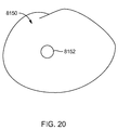
- FIG. 20 is an end view of a bone tunnel 8150 to receive body 8106 .
- a guide wire 8152 is in the center of the tunnel 8150 .
- the guide wire 8152 may be inserted into bone to establish a desired trajectory for the device 8100 .
- a drill (not shown) may then be used to create the tunnel 8150 .
- the first component 8102 may be inserted into the bone along the trajectory so that the body 8106 is coaxial with the tunnel 8150 . This may be accomplished, for example, by using an inserter tool (not shown) which includes a portion that may mimic the size and shape of body 8112 and arm 8114 , and may include a cannulation to receive the guide wire 8152 .
- This portion of the inserter tool may be inserted into the hole 8118 and slot 8120 , and the tool and component 8102 advanced together over the guide wire 8152 until the component 8102 is fully seated.
- the arm 8108 and blade 8110 may cut through bone, or may follow a pre-cut path through bone.
- the inserter tool may be withdrawn, and the second component may be inserted into the bone along the trajectory so that the body 8112 and arm 8114 are received in the hole 8118 and slot 8120 .
- This example may provide for some amount of angular adjustment between the first and second components due to the cylindrical mating interface.
- FIG. 21 illustrates yet another fusion device 9100 .
- This example is a two-part device with a first component 9102 and a second component 9104 .
- the first and second components may share some of the characteristics of the preceding example of FIG. 19 , with the exception that device 9100 includes a different interconnection.
- the first component 9102 includes a body 9106 , an arm 9108 or web, and a blade 9110 .
- the body 9106 forms a channel beside the arm 9108 .
- the body 9106 may be described as a recurved or bent portion of the arm 9108 .
- the second component 9104 includes a body 9112 , an arm 9114 or web, and a blade 9116 .
- the body 9112 is shaped like body 9106 .
- the first and second components 9102 , 9104 may be connected by hooking the bodies 9106 , 9112 together along more or less the entire length of the device 9100 . This example may also afford some angular adjustment between the first and second components 9102 , 9104 as a consequence of the interconnection.
- FIG. 22 illustrates yet another fusion device 2000 implanted across a sacroiliac joint line 4 .
- This example is a three-part device with a cage 2002 and two anchors 2006 .
- the cage 2002 is cylindrical and includes two opposing slots 2004 which communicate with an internal bore 2024 .
- a leading end 2020 of the cage may be tapered.
- the cage 2002 may include external threads 2022 , ridges, teeth, or the like to enhance fixation.
- Each anchor includes an arm 2010 , a blade 2012 along an edge of the arm and extending transverse to the arm, and a fixation feature 2026 extending along an opposite edge of the arm.
- the arm may have a concave and/or sharpened leading edge 2034 .
- Leading and/or side edges 2028 of the blade 2012 may be sharpened, and the blade may include a sharpened tip 2030 .
- the fixation feature 2026 in this example is a semicircular enlargement.
- the fixation feature 2026 may include a tapered or sharpened tip 2032 .
- FIG. 24 illustrates yet another fusion device 3000 , which may be monolithically formed or permanently assembled, such as by welding.
- Device 3000 includes a first arm 3002 , a second arm 3004 , and a beam 3006 between the arms 3002 , 3004 .
- the arms may be wedge shaped in at least one view so that each arm has a tapered or sharpened leading tip 3008 . Other leading or side edges may also be sharpened as described for other examples.
- the arms 3002 , 3004 may also be oriented with an acute angle 3010 between them so that the tips 3008 are farther apart than the opposite ends of the arms 3002 , 3004 .
- FIG. 25 illustrates device 3000 partially inserted into bone along an anterior-posterior trajectory, or a posterior approach.
- One arm 3002 is partially inserted into a sacrum 1
- the other arm 3004 is partially inserted into an ilium 2
- the beam 3006 extends across the sacroiliac joint line 4 .
- FIG. 26 illustrates yet another fusion device 4000 . Similar to other examples herein, device 4000 is illustrated with two anchors 4006 extending from opposite sides of a cage 4002 . Fusion device 4000 may carry bone graft material or other therapeutic agents in recesses 4008 in the cage 4002 or anchors 4006 , as shown in FIGS. 26-27 .
- FIG. 28 is a posterior view showing device 4000 implanted across a sacroiliac joint line 4 .
- FIG. 29 illustrates yet another fusion device 5000 , which includes a cylindrical cage 5002 with three dovetail slots 5004 evenly spaced around a generally circular perimeter, and three anchors 5006 .
- FIG. 30 is an exploded view of the device 5000 .
- Coupled is defined as connected, although not necessarily directly, and not necessarily mechanically.
- a step of a method or an element of a device that “comprises,” “has,” “includes” or “contains” one or more features, possesses those one or more features, but is not limited to possessing only those one or more features.
- a device or structure that is configured in a certain way is configured in at least that way, but may also be configured in ways that are not listed.
- the present invention may be embodied in other specific forms without departing from its spirit or essential characteristics. It is appreciated that various features of the above-described examples can be mixed and matched to form a variety of other alternatives. For example, a blade configuration from one or more fixation device examples may be found on the other fixation device examples disclosed herein. Similarly, manufacturing, assembly or implantation methods described for one fixation device or component may be used in the manufacture, assembly or implantation of the other fixation devices or components disclosed herein. As such, the described embodiments are to be considered in all respects only as illustrative and not restrictive. The scope of the invention is, therefore, indicated by the appended claims rather than by the foregoing description. All changes which come within the meaning and range of equivalency of the claims are to be embraced within their scope.
Abstract
Description
Claims (17)
Priority Applications (1)
| Application Number | Priority Date | Filing Date | Title |
|---|---|---|---|
| US13/666,956 US9615856B2 (en) | 2011-11-01 | 2012-11-01 | Sacroiliac fusion cage |
Applications Claiming Priority (2)
| Application Number | Priority Date | Filing Date | Title |
|---|---|---|---|
| US201161554395P | 2011-11-01 | 2011-11-01 | |
| US13/666,956 US9615856B2 (en) | 2011-11-01 | 2012-11-01 | Sacroiliac fusion cage |
Publications (2)
| Publication Number | Publication Date |
|---|---|
| US20130144343A1 US20130144343A1 (en) | 2013-06-06 |
| US9615856B2 true US9615856B2 (en) | 2017-04-11 |
Family
ID=48524541
Family Applications (1)
| Application Number | Title | Priority Date | Filing Date |
|---|---|---|---|
| US13/666,956 Active 2033-07-14 US9615856B2 (en) | 2011-11-01 | 2012-11-01 | Sacroiliac fusion cage |
Country Status (1)
| Country | Link |
|---|---|
| US (1) | US9615856B2 (en) |
Cited By (29)
| Publication number | Priority date | Publication date | Assignee | Title |
|---|---|---|---|---|
| US9839448B2 (en) | 2013-10-15 | 2017-12-12 | Si-Bone Inc. | Implant placement |
| US20180092748A1 (en) * | 2010-01-13 | 2018-04-05 | Jcbd, Llc | Sacroiliac joint implant system |
| US9949843B2 (en) | 2004-08-09 | 2018-04-24 | Si-Bone Inc. | Apparatus, systems, and methods for the fixation or fusion of bone |
| US10166033B2 (en) | 2014-09-18 | 2019-01-01 | Si-Bone Inc. | Implants for bone fixation or fusion |
| US10194962B2 (en) | 2014-09-18 | 2019-02-05 | Si-Bone Inc. | Matrix implant |
| US10201427B2 (en) | 2012-03-09 | 2019-02-12 | Si-Bone Inc. | Integrated implant |
| US10363140B2 (en) | 2012-03-09 | 2019-07-30 | Si-Bone Inc. | Systems, device, and methods for joint fusion |
| US10376206B2 (en) | 2015-04-01 | 2019-08-13 | Si-Bone Inc. | Neuromonitoring systems and methods for bone fixation or fusion procedures |
| US10426533B2 (en) | 2012-05-04 | 2019-10-01 | Si-Bone Inc. | Fenestrated implant |
| US10456272B2 (en) * | 2017-03-03 | 2019-10-29 | Engage Uni Llc | Unicompartmental knee arthroplasty |
| US10492841B2 (en) | 2014-07-10 | 2019-12-03 | Crossroads Extremity Systems, Llc | Bone implant and means of insertion |
| USD892331S1 (en) | 2017-07-31 | 2020-08-04 | Crossroads Extremity Systems, Llc | Osteosynthesis clip features |
| US10945725B2 (en) | 2017-02-06 | 2021-03-16 | Crossroads Extremity Systems, Llc | Implant inserter |
| US10959758B2 (en) | 2013-03-15 | 2021-03-30 | Si-Bone Inc. | Implants for spinal fixation or fusion |
| US11116519B2 (en) | 2017-09-26 | 2021-09-14 | Si-Bone Inc. | Systems and methods for decorticating the sacroiliac joint |
| US11147688B2 (en) | 2013-10-15 | 2021-10-19 | Si-Bone Inc. | Implant placement |
| US11166821B2 (en) | 2018-11-19 | 2021-11-09 | John Anthony Sazy | Implants and implantation techniques for sacroiliac joint fusion |
| US11179149B2 (en) | 2017-02-07 | 2021-11-23 | Crossroads Extremity Systems, Llc | Counter-torque implant |
| US11197763B2 (en) | 2010-12-16 | 2021-12-14 | Engage Medical Holdings, Llc | Arthroplasty systems and methods |
| US11202626B2 (en) | 2014-07-10 | 2021-12-21 | Crossroads Extremity Systems, Llc | Bone implant with means for multi directional force and means of insertion |
| US11234830B2 (en) | 2019-02-14 | 2022-02-01 | Si-Bone Inc. | Implants for spinal fixation and or fusion |
| US11369419B2 (en) | 2019-02-14 | 2022-06-28 | Si-Bone Inc. | Implants for spinal fixation and or fusion |
| USD961081S1 (en) | 2020-11-18 | 2022-08-16 | Crossroads Extremity Systems, Llc | Orthopedic implant |
| US11540928B2 (en) | 2017-03-03 | 2023-01-03 | Engage Uni Llc | Unicompartmental knee arthroplasty |
| US11571245B2 (en) | 2019-11-27 | 2023-02-07 | Si-Bone Inc. | Bone stabilizing implants and methods of placement across SI joints |
| US11633292B2 (en) | 2005-05-24 | 2023-04-25 | Si-Bone Inc. | Apparatus, systems, and methods for the fixation or fusion of bone |
| US11752011B2 (en) | 2020-12-09 | 2023-09-12 | Si-Bone Inc. | Sacro-iliac joint stabilizing implants and methods of implantation |
| US11871899B2 (en) | 2013-12-20 | 2024-01-16 | Crossroads Extremity Systems, Llc | Bone plates with dynamic elements |
| US11951010B2 (en) | 2021-12-10 | 2024-04-09 | Surgentec, Llc | Sacroiliac joint stabilization system |
Families Citing this family (35)
| Publication number | Priority date | Publication date | Assignee | Title |
|---|---|---|---|---|
| US10779958B2 (en) | 2014-12-22 | 2020-09-22 | Beacon Biomedical, Llc | Sacroiliac joint fusion systems and methods |
| US9421109B2 (en) | 2010-01-13 | 2016-08-23 | Jcbd, Llc | Systems and methods of fusing a sacroiliac joint |
| WO2014015309A1 (en) | 2012-07-20 | 2014-01-23 | Jcbd, Llc | Orthopedic anchoring system and methods |
| CN105287056B (en) * | 2010-01-13 | 2018-10-16 | Jcbd公司 | sacroiliac joint fixation fusion system |
| US9381045B2 (en) | 2010-01-13 | 2016-07-05 | Jcbd, Llc | Sacroiliac joint implant and sacroiliac joint instrument for fusing a sacroiliac joint |
| US9333090B2 (en) | 2010-01-13 | 2016-05-10 | Jcbd, Llc | Systems for and methods of fusing a sacroiliac joint |
| JP2013538076A (en) * | 2010-07-27 | 2013-10-10 | リチャード エス. ジン, | System for sacroiliac stabilization |
| CN105326533B (en) | 2010-09-24 | 2017-12-08 | 斯博特威尔丁股份有限公司 | Apparatus and method for suture holdfast to be fixed in sclerous tissues |
| JP6393477B2 (en) | 2010-09-24 | 2018-09-19 | スポートウェルディング・ゲゼルシャフト・ミット・ベシュレンクテル・ハフツングSportwelding Gmbh | Suture anchor and method for securing a suture to hard tissue |
| US9386976B2 (en) | 2011-01-28 | 2016-07-12 | Sportwelding Gmbh | Method and device for fixating a suture anchor with a suture in hard tissue |
| KR101998429B1 (en) | 2011-01-28 | 2019-07-09 | 스포트벨딩 게엠베하 | Device and method for fixating a suture anchor with a suture or a headed anchor in hard tissue |
| US9265620B2 (en) | 2011-03-18 | 2016-02-23 | Raed M. Ali, M.D., Inc. | Devices and methods for transpedicular stabilization of the spine |
| US8790375B2 (en) * | 2011-03-18 | 2014-07-29 | Raed M. Ali, M.D., Inc. | Transpedicular access to intervertebral spaces and related spinal fusion systems and methods |
| US20140012340A1 (en) * | 2012-07-05 | 2014-01-09 | Warsaw Orthopedic, Inc. | Sacro-iliac joint implant system and method |
| US10687962B2 (en) | 2013-03-14 | 2020-06-23 | Raed M. Ali, M.D., Inc. | Interbody fusion devices, systems and methods |
| US9730737B2 (en) * | 2013-03-14 | 2017-08-15 | Atlas Spine, Inc. | Facet fixation with anchor wire |
| WO2014159762A1 (en) | 2013-03-14 | 2014-10-02 | Raed M. Ali, M.D., Inc. | Lateral interbody fusion devices, systems and methods |
| US9717539B2 (en) | 2013-07-30 | 2017-08-01 | Jcbd, Llc | Implants, systems, and methods for fusing a sacroiliac joint |
| US10245087B2 (en) | 2013-03-15 | 2019-04-02 | Jcbd, Llc | Systems and methods for fusing a sacroiliac joint and anchoring an orthopedic appliance |
| US9119732B2 (en) | 2013-03-15 | 2015-09-01 | Orthocision, Inc. | Method and implant system for sacroiliac joint fixation and fusion |
| US9826986B2 (en) | 2013-07-30 | 2017-11-28 | Jcbd, Llc | Systems for and methods of preparing a sacroiliac joint for fusion |
| WO2015017593A1 (en) | 2013-07-30 | 2015-02-05 | Jcbd, Llc | Systems for and methods of fusing a sacroiliac joint |
| US9801546B2 (en) | 2014-05-27 | 2017-10-31 | Jcbd, Llc | Systems for and methods of diagnosing and treating a sacroiliac joint disorder |
| US10045803B2 (en) | 2014-07-03 | 2018-08-14 | Mayo Foundation For Medical Education And Research | Sacroiliac joint fusion screw and method |
| CN104451287A (en) * | 2014-12-12 | 2015-03-25 | 西南铝业(集团)有限责任公司 | Preparation method of 5A06 aluminum alloy ingot |
| US10376367B2 (en) | 2015-07-02 | 2019-08-13 | First Ray, LLC | Orthopedic fasteners, instruments and methods |
| US20170209285A1 (en) * | 2016-01-22 | 2017-07-27 | Imi Co., Ltd. | Intervertebral fusion cage combined with fixing blade |
| US10413332B2 (en) | 2016-04-25 | 2019-09-17 | Imds Llc | Joint fusion implant and methods |
| US9833321B2 (en) | 2016-04-25 | 2017-12-05 | Imds Llc | Joint fusion instrumentation and methods |
| US20180125600A1 (en) * | 2016-11-07 | 2018-05-10 | In2Bones Usa, Llc | Sizer Instrument And Methods Thereof |
| US10603055B2 (en) | 2017-09-15 | 2020-03-31 | Jcbd, Llc | Systems for and methods of preparing and fusing a sacroiliac joint |
| JP2022525319A (en) * | 2019-03-19 | 2022-05-12 | クロスローズ エクストリミティ システムズ リミテッド ライアビリティ カンパニー | Modular bone implant device and means of insertion |
| US11857420B2 (en) * | 2019-03-19 | 2024-01-02 | Brad MULLIN | Sacroiliac joint fusion implants and methods |
| EP4072452A4 (en) * | 2019-12-09 | 2023-12-20 | SI-Bone, Inc. | Sacro-iliac joint stabilizing implants and methods of implantation |
| US20230181184A1 (en) * | 2021-12-10 | 2023-06-15 | Wright Medical Technology, Inc. | Stabilization devices |
Citations (219)
| Publication number | Priority date | Publication date | Assignee | Title |
|---|---|---|---|---|
| US3486505A (en) | 1967-05-22 | 1969-12-30 | Gordon M Morrison | Orthopedic surgical instrument |
| US3641590A (en) | 1970-01-16 | 1972-02-15 | Arthur A Michele | Acetabular replacement prosthesis and method of assembling |
| US3650309A (en) | 1969-02-12 | 1972-03-21 | Robert Neuschotz | Structure and use of fasteners having locking keys |
| US3842825A (en) | 1973-11-12 | 1974-10-22 | R Wagner | Hip fixation device |
| US3848276A (en) | 1973-05-03 | 1974-11-19 | Y Martinez | Knee implant device |
| US3882917A (en) | 1970-04-03 | 1975-05-13 | Litton Industrial Products | Self-locking thread |
| US3896504A (en) | 1972-10-14 | 1975-07-29 | Artur Fischer | Hip joint prosthesis |
| US3907017A (en) | 1974-09-30 | 1975-09-23 | Glenn W Stanwick | Interfering thread form |
| US3927503A (en) | 1973-12-26 | 1975-12-23 | Standard Pressed Steel Co | Prevailing torque fastener |
| US4011602A (en) | 1975-10-06 | 1977-03-15 | Battelle Memorial Institute | Porous expandable device for attachment to bone tissue |
| US4047524A (en) | 1975-04-28 | 1977-09-13 | Downs Surgical Limited | Surgical implant spinal staple |
| US4260005A (en) | 1977-11-09 | 1981-04-07 | Vsi Corporation | Self-locking fastener, fastener system, and process |
| US4349955A (en) | 1976-05-07 | 1982-09-21 | Taper Line, Inc. | Method of locking a male member to a female member |
| US4355429A (en) | 1979-01-26 | 1982-10-26 | Osteo Ag | Slide prosthesis for the knee joint |
| US4484570A (en) | 1980-05-28 | 1984-11-27 | Synthes Ltd. | Device comprising an implant and screws for fastening said implant to a bone, and a device for connecting two separated pieces of bone |
| US4501269A (en) | 1981-12-11 | 1985-02-26 | Washington State University Research Foundation, Inc. | Process for fusing bone joints |
| EP0179695A1 (en) | 1984-09-26 | 1986-04-30 | Pierre Kehr | Vertebral prosthesis, in particular for cervical vertebrae |
| US4611581A (en) | 1983-12-16 | 1986-09-16 | Acromed Corporation | Apparatus for straightening spinal columns |
| US4642869A (en) | 1984-02-07 | 1987-02-17 | Multifastener Corporation | Process of attaching a nut to a plate-shaped workpiece |
| US4716893A (en) | 1985-03-11 | 1988-01-05 | Artur Fischer | Bone fastener |
| US4764067A (en) | 1985-11-22 | 1988-08-16 | Jsm Screw Co., Ltd. | Screw with groove for self-lock and method and rolling flat die for manufacturing the same |
| US4820305A (en) | 1986-11-03 | 1989-04-11 | Harms Juergen | Place holder, in particular for a vertebra body |
| US4834757A (en) | 1987-01-22 | 1989-05-30 | Brantigan John W | Prosthetic implant |
| US4838891A (en) | 1984-11-28 | 1989-06-13 | Branemark Per Ingvar | Joint prothesis |
| US4865607A (en) | 1985-10-02 | 1989-09-12 | Ulrich Witzel | Tibial plate for a knee-joint endoprosthesis |
| US4874389A (en) | 1987-12-07 | 1989-10-17 | Downey Ernest L | Replacement disc |
| US4930962A (en) | 1988-12-01 | 1990-06-05 | Pac-Fasteners, An Affiliate Of Peterson American Corp. | Nut and stud assembly |
| US4946378A (en) | 1987-11-24 | 1990-08-07 | Asahi Kogaku Kogyo Kabushiki Kaisha | Artificial intervertebral disc |
| US4957496A (en) | 1988-11-11 | 1990-09-18 | Mecron Medizinische Produkte Gmbh | Slotted slide plate assembly for osteosynthesis |
| US5002576A (en) | 1988-06-06 | 1991-03-26 | Mecron Medizinische Produkte Gmbh | Intervertebral disk endoprosthesis |
| US5019103A (en) | 1990-02-05 | 1991-05-28 | Boehringer Mannheim Corporation | Tibial wedge system |
| US5074880A (en) | 1988-12-20 | 1991-12-24 | S.P.O.R.T. | Anchoring device for knee prosthesis |
| US5147361A (en) | 1989-11-29 | 1992-09-15 | Asahi Kogaku Kogyo Kabushiki Kaisha | Vertebral connecting plate |
| US5163960A (en) | 1990-06-28 | 1992-11-17 | Bonutti Peter M | Surgical devices assembled using heat bondable materials |
| US5192324A (en) | 1982-02-18 | 1993-03-09 | Howmedica Inc. | Bone prosthesis with porous coating |
| US5192327A (en) | 1991-03-22 | 1993-03-09 | Brantigan John W | Surgical prosthetic implant for vertebrae |
| US5306309A (en) | 1992-05-04 | 1994-04-26 | Calcitek, Inc. | Spinal disk implant and implantation kit |
| US5314477A (en) | 1990-03-07 | 1994-05-24 | J.B.S. Limited Company | Prosthesis for intervertebral discs and instruments for implanting it |
| US5431658A (en) | 1994-02-14 | 1995-07-11 | Moskovich; Ronald | Facilitator for vertebrae grafts and prostheses |
| US5443515A (en) | 1994-01-26 | 1995-08-22 | Implex Corporation | Vertebral body prosthetic implant with slidably positionable stabilizing member |
| USD364462S (en) | 1994-03-28 | 1995-11-21 | Michelson Gary K | Spinal fixation staple |
| US5507816A (en) | 1991-12-04 | 1996-04-16 | Customflex Limited | Spinal vertebrae implants |
| US5514180A (en) | 1994-01-14 | 1996-05-07 | Heggeness; Michael H. | Prosthetic intervertebral devices |
| USD378409S (en) | 1995-10-30 | 1997-03-11 | Michelson Gary K | Spinal fixation staple |
| US5609635A (en) | 1988-06-28 | 1997-03-11 | Michelson; Gary K. | Lordotic interbody spinal fusion implants |
| US5658337A (en) | 1994-05-23 | 1997-08-19 | Spine-Tech, Inc. | Intervertebral fusion implant |
| US5683394A (en) | 1995-09-29 | 1997-11-04 | Advanced Spine Fixation Systems, Inc. | Fusion mass constrainer |
| US5702449A (en) | 1995-06-07 | 1997-12-30 | Danek Medical, Inc. | Reinforced porous spinal implants |
| US5709683A (en) | 1995-12-19 | 1998-01-20 | Spine-Tech, Inc. | Interbody bone implant having conjoining stabilization features for bony fusion |
| US5713899A (en) | 1995-04-27 | 1998-02-03 | Societe Jbs Sa | Cervical cage designed for the performance of intersomatic arthrodesis |
| US5769852A (en) | 1993-04-27 | 1998-06-23 | Medevelop Ab | Implantable anchoring element and anchoring assembly for prostheses |
| US5788701A (en) | 1995-12-21 | 1998-08-04 | Johnson & Johnson Professional, Inc. | Instrument system for knee prothesis implantation with universal handle or slap hammer |
| US5800550A (en) | 1996-03-13 | 1998-09-01 | Sertich; Mario M. | Interbody fusion cage |
| US5853414A (en) | 1991-05-09 | 1998-12-29 | Groiso; Jorge A. | Elastic clip for osteosynthesis |
| US5893890A (en) | 1994-03-18 | 1999-04-13 | Perumala Corporation | Rotating, locking intervertebral disk stabilizer and applicator |
| US5893889A (en) | 1997-06-20 | 1999-04-13 | Harrington; Michael | Artificial disc |
| US5993476A (en) | 1996-12-03 | 1999-11-30 | Groiso; Jorge A. | Surgical clip and method |
| US6053916A (en) * | 1999-02-17 | 2000-04-25 | Moore; Michael R. | Sacroiliac implant |
| US6063121A (en) | 1998-07-29 | 2000-05-16 | Xavier; Ravi | Vertebral body prosthesis |
| US6096080A (en) | 1998-05-06 | 2000-08-01 | Cortek, Inc. | Apparatus for spinal fusion using implanted devices |
| US6102949A (en) | 1997-12-03 | 2000-08-15 | Biedermann Motech Gmbh | Intervertebrae implant |
| US6113638A (en) | 1999-02-26 | 2000-09-05 | Williams; Lytton A. | Method and apparatus for intervertebral implant anchorage |
| US6235059B1 (en) | 1996-04-03 | 2001-05-22 | Scient'x (Societe A Responsabilite Limitee) | Intersomatic setting and fusion system |
| US6325805B1 (en) | 1999-04-23 | 2001-12-04 | Sdgi Holdings, Inc. | Shape memory alloy staple |
| US6336928B1 (en) | 1996-10-18 | 2002-01-08 | Depuy France | Device for securing at least two vertebrae |
| US20020035400A1 (en) | 2000-08-08 | 2002-03-21 | Vincent Bryan | Implantable joint prosthesis |
| US20020049447A1 (en) | 2000-08-29 | 2002-04-25 | Li Medical Technologies, Inc. | Expandable surgical fastener and method |
| US6402785B1 (en) | 1999-06-04 | 2002-06-11 | Sdgi Holdings, Inc. | Artificial disc implant |
| US6413278B1 (en) | 1998-03-30 | 2002-07-02 | J. Alexander Marchosky | Prosthetic system |
| US6432107B1 (en) | 2000-01-15 | 2002-08-13 | Bret A. Ferree | Enhanced surface area spinal fusion devices |
| US20020116165A1 (en) | 2001-02-13 | 2002-08-22 | El-Ghoroury Hussein S. | Matched instruction set processor systems and method, system, and apparatus to efficiently design and implement matched instruction set processor systems by mapping system designs to re-configurable hardware platforms |
| US6447524B1 (en) | 2000-10-19 | 2002-09-10 | Ethicon Endo-Surgery, Inc. | Fastener for hernia mesh fixation |
| US6447546B1 (en) | 2000-08-11 | 2002-09-10 | Dale G. Bramlet | Apparatus and method for fusing opposing spinal vertebrae |
| US6458159B1 (en) | 2000-08-15 | 2002-10-01 | John S. Thalgott | Disc prosthesis |
| US20020147499A1 (en) | 2001-02-26 | 2002-10-10 | Shea Jeffrey J. | Locking systems for implants |
| US20020147454A1 (en) | 2001-04-10 | 2002-10-10 | Neto Aziz Rassi | Building configuration introduced in a surgical-use screw |
| US20020165613A1 (en) | 2001-05-04 | 2002-11-07 | Chih-I Lin | Intervertebral fixation device having one or more bracing elements |
| US20030045940A1 (en) | 2001-08-24 | 2003-03-06 | Robert Eberlein | Artificial intervertebral disc |
| US20030060884A1 (en) | 1999-05-10 | 2003-03-27 | Fell Barry M. | Surgically implantable knee prosthesis having keels |
| US6558424B2 (en) | 2001-06-28 | 2003-05-06 | Depuy Acromed | Modular anatomic fusion device |
| US6582468B1 (en) | 1998-12-11 | 2003-06-24 | Spryker Spine | Intervertebral disc prosthesis with compressible body |
| WO2003053290A1 (en) | 2001-12-12 | 2003-07-03 | Vita Special Purpose Corporation | Bioactive spinal implants and method of manufacture thereof |
| US6610093B1 (en) | 2000-07-28 | 2003-08-26 | Perumala Corporation | Method and apparatus for stabilizing adjacent vertebrae |
| US6620198B2 (en) | 1999-10-07 | 2003-09-16 | Exactech, Inc. | Composite bearing inserts for total knee joints |
| US20030195632A1 (en) | 2001-02-06 | 2003-10-16 | Foley Kevin T. | Spinal implant with attached ligament |
| US20030195517A1 (en) | 1999-01-25 | 2003-10-16 | Michelson Gary K. | Instrumentation for creating an intervertebral space for receiving an implant |
| US6652533B2 (en) | 2001-09-20 | 2003-11-25 | Depuy Acromed, Inc. | Medical inserter tool with slaphammer |
| US20040030336A1 (en) | 2002-08-06 | 2004-02-12 | Khanna Rohit Kumar | Anterior cervical spine stabilization method and system |
| US20040030339A1 (en) | 2001-04-20 | 2004-02-12 | Wack Michael A. | Dual locking plate and associated method |
| US6716245B2 (en) | 2000-07-12 | 2004-04-06 | Spine Next | Intersomatic implant |
| US20040073315A1 (en) | 2002-04-25 | 2004-04-15 | Justin Daniel F. | Modular bone implant, tools, and method |
| US6726720B2 (en) | 2002-03-27 | 2004-04-27 | Depuy Spine, Inc. | Modular disc prosthesis |
| US20040083005A1 (en) | 1998-12-22 | 2004-04-29 | Magnus Jacobsson | Method of anchoring a prosthesis structure |
| US6740118B2 (en) | 2002-01-09 | 2004-05-25 | Sdgi Holdings, Inc. | Intervertebral prosthetic joint |
| US6743256B2 (en) | 2000-10-11 | 2004-06-01 | Michael D. Mason | Graftless spinal fusion device |
| US6755841B2 (en) | 2000-05-08 | 2004-06-29 | Depuy Acromed, Inc. | Medical installation tool |
| US20040148028A1 (en) | 2002-12-19 | 2004-07-29 | Ferree Bret A. | Artificial disc replacement (ADR) extraction methods and apparatus |
| US6770096B2 (en) | 1999-07-01 | 2004-08-03 | Spinevision S.A. | Interbody spinal stabilization cage and spinal stabilization method |
| WO2004071359A1 (en) | 2003-02-12 | 2004-08-26 | Sdgi Holdings Inc. | Articular disc prosthesis for lateral insertion |
| US20040176853A1 (en) | 2003-03-05 | 2004-09-09 | Sennett Andrew R. | Apparatus and method for spinal fusion using posteriorly implanted devices |
| US20040199254A1 (en) | 2001-07-13 | 2004-10-07 | Christian Louis | Vertebral cage device with modular fixation |
| US6802863B2 (en) | 2002-03-13 | 2004-10-12 | Cross Medical Products, Inc. | Keeled prosthetic nucleus |
| US20040254581A1 (en) | 2003-02-04 | 2004-12-16 | Leclair Walter J. | Furcated bone screw |
| US20050004672A1 (en) | 1995-10-16 | 2005-01-06 | John Pafford | Bone grafts |
| US20050014919A1 (en) | 2001-06-15 | 2005-01-20 | Hyoe Hatakeyama | Lignin-based polyurethane and process for producing the same |
| WO2005051243A2 (en) | 2003-10-30 | 2005-06-09 | Steven Streatfield Gill | An intervertebral prosthesis |
| US20050149192A1 (en) | 2003-11-20 | 2005-07-07 | St. Francis Medical Technologies, Inc. | Intervertebral body fusion cage with keels and implantation method |
| US20050165408A1 (en) | 2004-01-26 | 2005-07-28 | Puno Rolando M. | Methods and instrumentation for inserting intervertebral grafts and devices |
| US20050171607A1 (en) | 2000-06-13 | 2005-08-04 | Michelson Gary K. | Manufactured bone composite implant shaped to conform to a prepared implantation space |
| US20050177239A1 (en) | 1995-09-04 | 2005-08-11 | Amiram Steinberg | Method and apparatus for computerized surgery |
| WO2005074841A1 (en) | 2004-01-30 | 2005-08-18 | Sdgi Holdings, Inc. | Anatomic implants designed to minimize instruments and surgical techniques |
| US20050192586A1 (en) | 2002-10-29 | 2005-09-01 | St. Francis Medical Technologies, Inc. | Method of preparing for an artificial intervertebral implant using tool |
| US20050216089A1 (en) | 1999-03-05 | 2005-09-29 | Michelson Gary K | Arcuate interbody spinal fusion implant having a reduced width and an anatomically conformed trailing end |
| US6969390B2 (en) | 1997-02-11 | 2005-11-29 | Michelson Gary K | Anterior cervical plating system and bone screw |
| US6972035B2 (en) | 2000-04-19 | 2005-12-06 | Michelson Gary K | Expandable threaded arcuate interbody spinal fusion implant with cylindrical configuration during insertion |
| US20050273108A1 (en) | 2003-08-05 | 2005-12-08 | Groiso Jorge A | Osteosynthesis clip and insertion tool for inserting an osteosynthesis clip into bone tissue fragments |
| US20060004453A1 (en) | 2004-06-30 | 2006-01-05 | Depuy Spine, Inc. | Ceramic disc prosthesis |
| US20060074421A1 (en) | 2003-05-08 | 2006-04-06 | Bickley Barry T | Fixation augmentation device and related techniques |
| US20060085071A1 (en) | 2003-02-06 | 2006-04-20 | Beat Lechmann | Intervertebral implant |
| US20060095136A1 (en) | 2004-11-03 | 2006-05-04 | Mcluen Design, Inc. | Bone fusion device |
| US7041135B2 (en) | 1999-05-05 | 2006-05-09 | Sdgi Holdings, Inc. | Interbody spinal fusion implants with single-lock for locking opposed screws |
| US7044972B2 (en) | 2001-01-30 | 2006-05-16 | Synthes Ag Chur | Bone implant, in particular, an inter-vertebral implant |
| WO2006051547A2 (en) | 2004-11-15 | 2006-05-18 | Disc-O-Tech Medical Technologies, Ltd. | Assembled prosthesis such as a disc |
| US7048766B2 (en) | 2003-06-06 | 2006-05-23 | Ferree Bret A | Methods and apparatus for total disc replacements with oblique keels |
| US20060111787A1 (en) | 2004-11-05 | 2006-05-25 | Bailie David S | Glenoid prosthesis and method of implanting same |
| US20060116769A1 (en) | 2004-11-26 | 2006-06-01 | Theirry Marnay | Intervertebral implant |
| US7056345B2 (en) | 2000-12-15 | 2006-06-06 | Spineology, Inc. | Annulus-reinforcing band |
| US7056344B2 (en) | 2001-11-06 | 2006-06-06 | Ldr Medical | Osseous anchoring device for a prosthesis |
| US7060097B2 (en) | 2003-03-31 | 2006-06-13 | Depuy Spine, Inc. | Method and apparatus for implant stability |
| US20060129238A1 (en) | 2004-10-26 | 2006-06-15 | Adam Paltzer | Spinal stabilization device and methods |
| WO2006074414A2 (en) | 2005-01-08 | 2006-07-13 | Alphaspine, Inc. | Modular disc device |
| US20060167461A1 (en) | 2003-03-31 | 2006-07-27 | Hawkins John R | Method and apparatus for artificial disc insertion |
| US7083652B2 (en) | 1998-05-13 | 2006-08-01 | Depuy Products, Inc. | Tibial tray with adjustable keel |
| US7083623B2 (en) | 1996-07-31 | 2006-08-01 | Sdgi Holdings, Inc. | Milling instrumentation and method for preparing a space between adjacent vertebral bodies |
| US20060178745A1 (en) | 2005-02-10 | 2006-08-10 | Depuy Spine, Inc. | Intervertebral prosthetic disc |
| US7115146B2 (en) | 2000-03-22 | 2006-10-03 | Boyer Ii Michael L | Multipiece implants formed of bone material |
| US7118580B1 (en) | 1999-09-14 | 2006-10-10 | Spine Solutions Inc. | Instrument for inserting intervertebral implants |
| US20060241641A1 (en) | 2005-04-22 | 2006-10-26 | Sdgi Holdings, Inc. | Methods and instrumentation for distraction and insertion of implants in a spinal disc space |
| US7128761B2 (en) | 2003-12-10 | 2006-10-31 | Axiomed Spine Corporation | Method and apparatus for replacing a damaged spinal disc |
| US20070010890A1 (en) | 2005-07-08 | 2007-01-11 | Howmedica Osteonics Corp. | Modular tibial baseplate |
| US7166110B2 (en) | 2004-01-09 | 2007-01-23 | Yundt Kent D | Method, system and apparatus for interbody fusion |
| US7166129B2 (en) | 1999-12-08 | 2007-01-23 | Warsaw Orthopedic, Inc. | Method for forming a spinal implant surface configuration |
| US7169182B2 (en) | 2001-07-16 | 2007-01-30 | Spinecore, Inc. | Implanting an artificial intervertebral disc |
| US20070050032A1 (en) | 2005-09-01 | 2007-03-01 | Spinal Kinetics, Inc. | Prosthetic intervertebral discs |
| US20070055376A1 (en) | 2002-02-02 | 2007-03-08 | Michelson Gary K | Spinal fusion implant having deployable bone engaging projections |
| US20070073404A1 (en) | 2005-09-23 | 2007-03-29 | Ralph Rashbaum | Intervertebral disc prosthesis |
| US7204852B2 (en) | 2002-12-13 | 2007-04-17 | Spine Solutions, Inc. | Intervertebral implant, insertion tool and method of inserting same |
| US20070106388A1 (en) | 2000-07-10 | 2007-05-10 | Sdgi Holdings, Inc. | Flanged interbody spinal fusion implants |
| US20070118145A1 (en) | 2005-11-24 | 2007-05-24 | Kay Fischer | Surgical guiding instrument |
| US20070123903A1 (en) | 2005-10-31 | 2007-05-31 | Depuy Spine, Inc. | Medical Device installation tool and methods of use |
| US20070142922A1 (en) | 2005-12-21 | 2007-06-21 | Lewis Paul P P | Modular hip cup assembly, fastener assembly & fastener |
| US7235105B2 (en) | 2003-09-18 | 2007-06-26 | Jackson Roger P | Threaded center line cage with winged end gap |
| US20070156241A1 (en) * | 2004-08-09 | 2007-07-05 | Reiley Mark A | Systems and methods for the fixation or fusion of bone |
| WO2007087366A2 (en) | 2006-01-25 | 2007-08-02 | Spinemedica Corporation | Spinal disc implants with flexible keels and methods of fabricating implants |
| US20070185375A1 (en) | 2006-02-06 | 2007-08-09 | Depuy Spine, Inc. | Medical device installation tool |
| US20070233244A1 (en) | 2006-03-28 | 2007-10-04 | Depuy Spine, Inc. | Artificial Disc Replacement Using Posterior Approach |
| US20070239278A1 (en) | 2006-04-06 | 2007-10-11 | Sdgi Holdings, Inc. | Intervertebral prosthetic devices and methods |
| US20070288021A1 (en) | 2006-06-07 | 2007-12-13 | Howmedica Osteonics Corp. | Flexible joint implant |
| US20070288005A1 (en) | 2006-04-05 | 2007-12-13 | Uri Arnin | Fixation of spinal prosthesis |
| US20070299529A1 (en) | 2006-06-22 | 2007-12-27 | Depuy Products, Inc. | Tibial insert having multiple keels |
| US20080015702A1 (en) | 2006-07-11 | 2008-01-17 | Ebi, L.P. | Intervertebral implantation apparatus |
| US7320707B2 (en) | 2003-11-05 | 2008-01-22 | St. Francis Medical Technologies, Inc. | Method of laterally inserting an artificial vertebral disk replacement implant with crossbar spacer |
| WO2008014258A2 (en) | 2006-07-24 | 2008-01-31 | Spine Solutions, Inc. | Intervertebral implant with keel |
| US7326248B2 (en) | 2001-03-09 | 2008-02-05 | Warsaw Orthopedic, Inc. | Expandable interbody spinal fusion implant with expansion constraining member and method for use thereof |
| WO2008021955A2 (en) | 2006-08-10 | 2008-02-21 | James Dwyer | Modular intervertebral disc prosthesis and method of replacing an intervertebral disc |
| US20080051901A1 (en) | 2006-07-28 | 2008-02-28 | Spinalmotion, Inc. | Spinal Prosthesis with Multiple Pillar Anchors |
| US7357817B2 (en) | 2005-05-19 | 2008-04-15 | Howmedica Osteonics Corp. | Modular keel tibial component |
| US20080103598A1 (en) | 2006-09-15 | 2008-05-01 | Trudeau Jeffrey L | System and Method for Sizing, Inserting and Securing Artificial Disc in Intervertebral Space |
| US20080132949A1 (en) | 2005-12-29 | 2008-06-05 | Joseph Aferzon | Apparatus and method for anterior intervertebral spinal fixation and fusion |
| US20080147203A1 (en) | 2006-12-15 | 2008-06-19 | Zimmer Technology, Inc. | Modular plate and keel provisionals |
| US20080154377A1 (en) | 2006-12-22 | 2008-06-26 | Voellmicke John C | Composite vertebral spacers and instrument |
| US7396365B2 (en) | 1998-10-30 | 2008-07-08 | Warsaw Orthopedic, Inc. | Method for inserting a fusion cage having a height substantially the same as the height between adjacent vertebral endplates |
| US20080177275A1 (en) | 2006-12-01 | 2008-07-24 | Charles Wing | Interbody distractor |
| US20080208345A1 (en) | 2005-10-27 | 2008-08-28 | Kinetic Spine Technologies, Inc. | Intervertebral implant |
| US20080249623A1 (en) | 2006-12-22 | 2008-10-09 | Qi-Bin Bao | Implant Restraint Device and Methods |
| US20080249575A1 (en) | 2007-04-03 | 2008-10-09 | Warsaw Orthopedic, Inc. | Anchor Member Locking Features |
| WO2008128367A1 (en) | 2007-04-20 | 2008-10-30 | Woodwelding Ag | Method for fastening an implant to bone tissue and corresponding implant system |
| US20080275455A1 (en) | 2006-08-16 | 2008-11-06 | Amicus, Llc | Apparatus and Methods for Inserting an Implant |
| US20080287957A1 (en) | 2007-05-18 | 2008-11-20 | Depuy Spine, Inc. | Insertion blade assembly and method of use |
| US20090005784A1 (en) | 2007-04-25 | 2009-01-01 | Spinal Elements, Inc. | Spinal implant distractor/inserter |
| US20090005870A1 (en) | 2007-06-26 | 2009-01-01 | John Riley Hawkins | Highly Lordosed Fusion Cage |
| US7481830B2 (en) | 1999-07-07 | 2009-01-27 | Children's Hospital Medical Center | Spinal correction system |
| US20090048604A1 (en) | 2007-08-13 | 2009-02-19 | Stryker Spine | Insertion instrument for intervertebral implants |
| US20090062921A1 (en) | 2001-01-23 | 2009-03-05 | Michelson Gary K | Implant with openings adapted to receive bone screws |
| US7503935B2 (en) | 2003-12-02 | 2009-03-17 | Kyphon Sarl | Method of laterally inserting an artificial vertebral disk replacement with translating pivot point |
| US20090088849A1 (en) | 2007-09-27 | 2009-04-02 | Warsaw Orthopedic, Inc. | Intervertebral Implant |
| US20090099601A1 (en) | 2007-10-11 | 2009-04-16 | International Spinal Innovations, Llc | Minimally invasive lateral intervertbral fixation system, device and method |
| US20090099602A1 (en) | 2007-09-11 | 2009-04-16 | Kamran Aflatoon | Method of lateral facet approach, decompression and fusion using screws and staples as well as arthroplasty |
| US20090138015A1 (en) * | 2007-11-19 | 2009-05-28 | Magellan Spine Technologies, Inc. | Spinal implants and methods |
| US7540882B2 (en) | 2001-04-02 | 2009-06-02 | Warsaw Orthopedic, Inc. | Artificial spinal fusion implant with asymmetrical leading end |
| USD594986S1 (en) | 2005-03-29 | 2009-06-23 | Nuvasive, Inc. | Intervertebral implant |
| US20090164020A1 (en) | 2007-11-28 | 2009-06-25 | Pioneer Surgical Technology, Inc. | Device for Securing an Implant to Tissue |
| US7556650B2 (en) | 2004-06-29 | 2009-07-07 | Spine Wave, Inc. | Methods for injecting a curable biomaterial into an intervertebral space |
| US7572293B2 (en) | 2005-06-30 | 2009-08-11 | Depuy Products, Inc. | Tibial insert and associated surgical method |
| US20090209967A1 (en) | 2005-02-25 | 2009-08-20 | Evans David E | Implant insertion apparatus and method of use |
| US20090259261A1 (en) * | 2004-08-09 | 2009-10-15 | Mark A Reiley | Systems and methods for the fixation or fusion of bone at or near a sacroiliac joint |
| US7611538B2 (en) | 2003-08-04 | 2009-11-03 | Zimmer Spine S.A.S. | Intervertebral disk prosthesis |
| US20100004747A1 (en) | 2008-07-07 | 2010-01-07 | Jin-Fu Lin | Trans-Vertebral and Intra-Vertebral Plate and Fusion Cage Device for Spinal Interbody Fusion and Method of Operation |
| US7658766B2 (en) | 2006-05-01 | 2010-02-09 | Warsaw Orthopedic, Inc. | Intervertebral implants with covered inner chamber and methods of use |
| WO2010039026A1 (en) | 2008-09-30 | 2010-04-08 | J. Van Straten Beheer B.V. | Ankle prosthesis and a tibial component therefor |
| US7695516B2 (en) | 2004-12-22 | 2010-04-13 | Ldr Medical | Intervertebral disc prosthesis |
| US20100185292A1 (en) * | 2009-01-22 | 2010-07-22 | Stephen Hochschuler | Apparatus and method for stabilizing adjacent bone portions |
| US7763076B2 (en) | 2003-04-04 | 2010-07-27 | Theken Spine, Llc | Artificial disc prosthesis |
| US20100201739A1 (en) | 2009-02-12 | 2010-08-12 | Sony Corporation | Liquid ejection apparatus |
| US20100204739A1 (en) | 2009-02-11 | 2010-08-12 | IMDS, Inc. | Intervertebral implant with integrated fixation |
| US20100268228A1 (en) * | 2009-03-20 | 2010-10-21 | Minsurg International, Inc. | Surgical methods and tools |
| US7837732B2 (en) | 2003-11-20 | 2010-11-23 | Warsaw Orthopedic, Inc. | Intervertebral body fusion cage with keels and implantation methods |
| US7922765B2 (en) * | 2004-08-09 | 2011-04-12 | Si-Bone, Inc. | Systems and methods for the fixation or fusion of bone |
| WO2011044879A1 (en) | 2009-10-12 | 2011-04-21 | Aap Implantate Ag | Modular system for anchoring and positioning components of implants |
| WO2011090508A1 (en) | 2010-01-22 | 2011-07-28 | Stephen Hochschuler | Apparatus and method for stabilizing adjacent bone portions |
| US8034076B2 (en) | 2000-10-23 | 2011-10-11 | Tyco Healthcare Group Lp | Absorbable fastener and applying apparatus |
| US20110264229A1 (en) * | 2010-01-13 | 2011-10-27 | Jcbd, Llc | Sacroiliac joint fixation system |
| US8100974B2 (en) | 2004-06-30 | 2012-01-24 | Synergy Disc Replacement, Inc. | Artificial spinal disc |
| US8105389B2 (en) | 2002-10-24 | 2012-01-31 | Biomet Manufacturing Corp. | Method and apparatus for wrist arthroplasty |
| US8133283B2 (en) | 2007-06-06 | 2012-03-13 | Kenneth Mitchell Wilson | Scapho-lunate fixation implants and methods of use |
| US20120083883A1 (en) * | 2010-07-27 | 2012-04-05 | Ginn Richard S | System and method for sacro-iliac stabilization |
| US8388667B2 (en) * | 2004-08-09 | 2013-03-05 | Si-Bone, Inc. | Systems and methods for the fixation or fusion of bone using compressive implants |
| US20140135927A1 (en) * | 2012-11-12 | 2014-05-15 | Paul Pavlov | Interbody interference implant and instrumentation |
| US9033993B2 (en) | 2009-11-03 | 2015-05-19 | Howmedica Osteonics Corp. | Intervertebral implant with integrated fixation |
-
2012
- 2012-11-01 US US13/666,956 patent/US9615856B2/en active Active
Patent Citations (236)
| Publication number | Priority date | Publication date | Assignee | Title |
|---|---|---|---|---|
| US3486505A (en) | 1967-05-22 | 1969-12-30 | Gordon M Morrison | Orthopedic surgical instrument |
| US3650309A (en) | 1969-02-12 | 1972-03-21 | Robert Neuschotz | Structure and use of fasteners having locking keys |
| US3641590A (en) | 1970-01-16 | 1972-02-15 | Arthur A Michele | Acetabular replacement prosthesis and method of assembling |
| US3882917A (en) | 1970-04-03 | 1975-05-13 | Litton Industrial Products | Self-locking thread |
| US3896504A (en) | 1972-10-14 | 1975-07-29 | Artur Fischer | Hip joint prosthesis |
| US3848276A (en) | 1973-05-03 | 1974-11-19 | Y Martinez | Knee implant device |
| US3842825A (en) | 1973-11-12 | 1974-10-22 | R Wagner | Hip fixation device |
| US3927503A (en) | 1973-12-26 | 1975-12-23 | Standard Pressed Steel Co | Prevailing torque fastener |
| US3907017A (en) | 1974-09-30 | 1975-09-23 | Glenn W Stanwick | Interfering thread form |
| US4047524A (en) | 1975-04-28 | 1977-09-13 | Downs Surgical Limited | Surgical implant spinal staple |
| US4011602A (en) | 1975-10-06 | 1977-03-15 | Battelle Memorial Institute | Porous expandable device for attachment to bone tissue |
| US4349955A (en) | 1976-05-07 | 1982-09-21 | Taper Line, Inc. | Method of locking a male member to a female member |
| US4260005A (en) | 1977-11-09 | 1981-04-07 | Vsi Corporation | Self-locking fastener, fastener system, and process |
| US4260005B1 (en) | 1977-11-09 | 1992-09-22 | Vsi Corp | |
| US4355429A (en) | 1979-01-26 | 1982-10-26 | Osteo Ag | Slide prosthesis for the knee joint |
| US4484570A (en) | 1980-05-28 | 1984-11-27 | Synthes Ltd. | Device comprising an implant and screws for fastening said implant to a bone, and a device for connecting two separated pieces of bone |
| US4501269A (en) | 1981-12-11 | 1985-02-26 | Washington State University Research Foundation, Inc. | Process for fusing bone joints |
| US5192324A (en) | 1982-02-18 | 1993-03-09 | Howmedica Inc. | Bone prosthesis with porous coating |
| US4611581A (en) | 1983-12-16 | 1986-09-16 | Acromed Corporation | Apparatus for straightening spinal columns |
| US4642869A (en) | 1984-02-07 | 1987-02-17 | Multifastener Corporation | Process of attaching a nut to a plate-shaped workpiece |
| EP0179695A1 (en) | 1984-09-26 | 1986-04-30 | Pierre Kehr | Vertebral prosthesis, in particular for cervical vertebrae |
| US4838891A (en) | 1984-11-28 | 1989-06-13 | Branemark Per Ingvar | Joint prothesis |
| US4716893A (en) | 1985-03-11 | 1988-01-05 | Artur Fischer | Bone fastener |
| US4865607A (en) | 1985-10-02 | 1989-09-12 | Ulrich Witzel | Tibial plate for a knee-joint endoprosthesis |
| US4764067A (en) | 1985-11-22 | 1988-08-16 | Jsm Screw Co., Ltd. | Screw with groove for self-lock and method and rolling flat die for manufacturing the same |
| US4820305A (en) | 1986-11-03 | 1989-04-11 | Harms Juergen | Place holder, in particular for a vertebra body |
| US4834757A (en) | 1987-01-22 | 1989-05-30 | Brantigan John W | Prosthetic implant |
| US4946378A (en) | 1987-11-24 | 1990-08-07 | Asahi Kogaku Kogyo Kabushiki Kaisha | Artificial intervertebral disc |
| US4874389A (en) | 1987-12-07 | 1989-10-17 | Downey Ernest L | Replacement disc |
| US5002576A (en) | 1988-06-06 | 1991-03-26 | Mecron Medizinische Produkte Gmbh | Intervertebral disk endoprosthesis |
| US5609635A (en) | 1988-06-28 | 1997-03-11 | Michelson; Gary K. | Lordotic interbody spinal fusion implants |
| US4957496A (en) | 1988-11-11 | 1990-09-18 | Mecron Medizinische Produkte Gmbh | Slotted slide plate assembly for osteosynthesis |
| US4930962A (en) | 1988-12-01 | 1990-06-05 | Pac-Fasteners, An Affiliate Of Peterson American Corp. | Nut and stud assembly |
| US5074880A (en) | 1988-12-20 | 1991-12-24 | S.P.O.R.T. | Anchoring device for knee prosthesis |
| US5147361A (en) | 1989-11-29 | 1992-09-15 | Asahi Kogaku Kogyo Kabushiki Kaisha | Vertebral connecting plate |
| US5019103A (en) | 1990-02-05 | 1991-05-28 | Boehringer Mannheim Corporation | Tibial wedge system |
| US5314477A (en) | 1990-03-07 | 1994-05-24 | J.B.S. Limited Company | Prosthesis for intervertebral discs and instruments for implanting it |
| US5163960A (en) | 1990-06-28 | 1992-11-17 | Bonutti Peter M | Surgical devices assembled using heat bondable materials |
| US5192327A (en) | 1991-03-22 | 1993-03-09 | Brantigan John W | Surgical prosthetic implant for vertebrae |
| US5853414A (en) | 1991-05-09 | 1998-12-29 | Groiso; Jorge A. | Elastic clip for osteosynthesis |
| US5507816A (en) | 1991-12-04 | 1996-04-16 | Customflex Limited | Spinal vertebrae implants |
| US5306309A (en) | 1992-05-04 | 1994-04-26 | Calcitek, Inc. | Spinal disk implant and implantation kit |
| US5769852A (en) | 1993-04-27 | 1998-06-23 | Medevelop Ab | Implantable anchoring element and anchoring assembly for prostheses |
| US5514180A (en) | 1994-01-14 | 1996-05-07 | Heggeness; Michael H. | Prosthetic intervertebral devices |
| US5443515A (en) | 1994-01-26 | 1995-08-22 | Implex Corporation | Vertebral body prosthetic implant with slidably positionable stabilizing member |
| US5431658A (en) | 1994-02-14 | 1995-07-11 | Moskovich; Ronald | Facilitator for vertebrae grafts and prostheses |
| US5893890A (en) | 1994-03-18 | 1999-04-13 | Perumala Corporation | Rotating, locking intervertebral disk stabilizer and applicator |
| USD364462S (en) | 1994-03-28 | 1995-11-21 | Michelson Gary K | Spinal fixation staple |
| US5658337A (en) | 1994-05-23 | 1997-08-19 | Spine-Tech, Inc. | Intervertebral fusion implant |
| US5713899A (en) | 1995-04-27 | 1998-02-03 | Societe Jbs Sa | Cervical cage designed for the performance of intersomatic arthrodesis |
| US5702449A (en) | 1995-06-07 | 1997-12-30 | Danek Medical, Inc. | Reinforced porous spinal implants |
| US20050177239A1 (en) | 1995-09-04 | 2005-08-11 | Amiram Steinberg | Method and apparatus for computerized surgery |
| US5683394A (en) | 1995-09-29 | 1997-11-04 | Advanced Spine Fixation Systems, Inc. | Fusion mass constrainer |
| US20050004672A1 (en) | 1995-10-16 | 2005-01-06 | John Pafford | Bone grafts |
| USD378409S (en) | 1995-10-30 | 1997-03-11 | Michelson Gary K | Spinal fixation staple |
| US5709683A (en) | 1995-12-19 | 1998-01-20 | Spine-Tech, Inc. | Interbody bone implant having conjoining stabilization features for bony fusion |
| US5788701A (en) | 1995-12-21 | 1998-08-04 | Johnson & Johnson Professional, Inc. | Instrument system for knee prothesis implantation with universal handle or slap hammer |
| US5800550A (en) | 1996-03-13 | 1998-09-01 | Sertich; Mario M. | Interbody fusion cage |
| US6235059B1 (en) | 1996-04-03 | 2001-05-22 | Scient'x (Societe A Responsabilite Limitee) | Intersomatic setting and fusion system |
| US7083623B2 (en) | 1996-07-31 | 2006-08-01 | Sdgi Holdings, Inc. | Milling instrumentation and method for preparing a space between adjacent vertebral bodies |
| US6336928B1 (en) | 1996-10-18 | 2002-01-08 | Depuy France | Device for securing at least two vertebrae |
| US5993476A (en) | 1996-12-03 | 1999-11-30 | Groiso; Jorge A. | Surgical clip and method |
| US6969390B2 (en) | 1997-02-11 | 2005-11-29 | Michelson Gary K | Anterior cervical plating system and bone screw |
| US5893889A (en) | 1997-06-20 | 1999-04-13 | Harrington; Michael | Artificial disc |
| US6102949A (en) | 1997-12-03 | 2000-08-15 | Biedermann Motech Gmbh | Intervertebrae implant |
| US6413278B1 (en) | 1998-03-30 | 2002-07-02 | J. Alexander Marchosky | Prosthetic system |
| US6096080A (en) | 1998-05-06 | 2000-08-01 | Cortek, Inc. | Apparatus for spinal fusion using implanted devices |
| US7083652B2 (en) | 1998-05-13 | 2006-08-01 | Depuy Products, Inc. | Tibial tray with adjustable keel |
| US6063121A (en) | 1998-07-29 | 2000-05-16 | Xavier; Ravi | Vertebral body prosthesis |
| US7396365B2 (en) | 1998-10-30 | 2008-07-08 | Warsaw Orthopedic, Inc. | Method for inserting a fusion cage having a height substantially the same as the height between adjacent vertebral endplates |
| US6582468B1 (en) | 1998-12-11 | 2003-06-24 | Spryker Spine | Intervertebral disc prosthesis with compressible body |
| US20040083005A1 (en) | 1998-12-22 | 2004-04-29 | Magnus Jacobsson | Method of anchoring a prosthesis structure |
| US20030195517A1 (en) | 1999-01-25 | 2003-10-16 | Michelson Gary K. | Instrumentation for creating an intervertebral space for receiving an implant |
| US6053916A (en) * | 1999-02-17 | 2000-04-25 | Moore; Michael R. | Sacroiliac implant |
| US6113638A (en) | 1999-02-26 | 2000-09-05 | Williams; Lytton A. | Method and apparatus for intervertebral implant anchorage |
| US20050216089A1 (en) | 1999-03-05 | 2005-09-29 | Michelson Gary K | Arcuate interbody spinal fusion implant having a reduced width and an anatomically conformed trailing end |
| US6325805B1 (en) | 1999-04-23 | 2001-12-04 | Sdgi Holdings, Inc. | Shape memory alloy staple |
| US7041135B2 (en) | 1999-05-05 | 2006-05-09 | Sdgi Holdings, Inc. | Interbody spinal fusion implants with single-lock for locking opposed screws |
| US20030060884A1 (en) | 1999-05-10 | 2003-03-27 | Fell Barry M. | Surgically implantable knee prosthesis having keels |
| US6402785B1 (en) | 1999-06-04 | 2002-06-11 | Sdgi Holdings, Inc. | Artificial disc implant |
| US6770096B2 (en) | 1999-07-01 | 2004-08-03 | Spinevision S.A. | Interbody spinal stabilization cage and spinal stabilization method |
| US7481830B2 (en) | 1999-07-07 | 2009-01-27 | Children's Hospital Medical Center | Spinal correction system |
| US8021403B2 (en) | 1999-07-07 | 2011-09-20 | Children's Hospital Medical Center | Spinal staple system |
| US7118580B1 (en) | 1999-09-14 | 2006-10-10 | Spine Solutions Inc. | Instrument for inserting intervertebral implants |
| US6620198B2 (en) | 1999-10-07 | 2003-09-16 | Exactech, Inc. | Composite bearing inserts for total knee joints |
| US7166129B2 (en) | 1999-12-08 | 2007-01-23 | Warsaw Orthopedic, Inc. | Method for forming a spinal implant surface configuration |
| US6432107B1 (en) | 2000-01-15 | 2002-08-13 | Bret A. Ferree | Enhanced surface area spinal fusion devices |
| US7115146B2 (en) | 2000-03-22 | 2006-10-03 | Boyer Ii Michael L | Multipiece implants formed of bone material |
| US6972035B2 (en) | 2000-04-19 | 2005-12-06 | Michelson Gary K | Expandable threaded arcuate interbody spinal fusion implant with cylindrical configuration during insertion |
| US6755841B2 (en) | 2000-05-08 | 2004-06-29 | Depuy Acromed, Inc. | Medical installation tool |
| US20050171607A1 (en) | 2000-06-13 | 2005-08-04 | Michelson Gary K. | Manufactured bone composite implant shaped to conform to a prepared implantation space |
| US20070106388A1 (en) | 2000-07-10 | 2007-05-10 | Sdgi Holdings, Inc. | Flanged interbody spinal fusion implants |
| US6716245B2 (en) | 2000-07-12 | 2004-04-06 | Spine Next | Intersomatic implant |
| US6610093B1 (en) | 2000-07-28 | 2003-08-26 | Perumala Corporation | Method and apparatus for stabilizing adjacent vertebrae |
| US20020035400A1 (en) | 2000-08-08 | 2002-03-21 | Vincent Bryan | Implantable joint prosthesis |
| US6447546B1 (en) | 2000-08-11 | 2002-09-10 | Dale G. Bramlet | Apparatus and method for fusing opposing spinal vertebrae |
| US6458159B1 (en) | 2000-08-15 | 2002-10-01 | John S. Thalgott | Disc prosthesis |
| US20020049447A1 (en) | 2000-08-29 | 2002-04-25 | Li Medical Technologies, Inc. | Expandable surgical fastener and method |
| US6743256B2 (en) | 2000-10-11 | 2004-06-01 | Michael D. Mason | Graftless spinal fusion device |
| US6447524B1 (en) | 2000-10-19 | 2002-09-10 | Ethicon Endo-Surgery, Inc. | Fastener for hernia mesh fixation |
| US8034076B2 (en) | 2000-10-23 | 2011-10-11 | Tyco Healthcare Group Lp | Absorbable fastener and applying apparatus |
| US7056345B2 (en) | 2000-12-15 | 2006-06-06 | Spineology, Inc. | Annulus-reinforcing band |
| US20090062921A1 (en) | 2001-01-23 | 2009-03-05 | Michelson Gary K | Implant with openings adapted to receive bone screws |
| US7044972B2 (en) | 2001-01-30 | 2006-05-16 | Synthes Ag Chur | Bone implant, in particular, an inter-vertebral implant |
| US20030195632A1 (en) | 2001-02-06 | 2003-10-16 | Foley Kevin T. | Spinal implant with attached ligament |
| US20020116165A1 (en) | 2001-02-13 | 2002-08-22 | El-Ghoroury Hussein S. | Matched instruction set processor systems and method, system, and apparatus to efficiently design and implement matched instruction set processor systems by mapping system designs to re-configurable hardware platforms |
| US20020147499A1 (en) | 2001-02-26 | 2002-10-10 | Shea Jeffrey J. | Locking systems for implants |
| US7326248B2 (en) | 2001-03-09 | 2008-02-05 | Warsaw Orthopedic, Inc. | Expandable interbody spinal fusion implant with expansion constraining member and method for use thereof |
| US7540882B2 (en) | 2001-04-02 | 2009-06-02 | Warsaw Orthopedic, Inc. | Artificial spinal fusion implant with asymmetrical leading end |
| US20020147454A1 (en) | 2001-04-10 | 2002-10-10 | Neto Aziz Rassi | Building configuration introduced in a surgical-use screw |
| US20040030339A1 (en) | 2001-04-20 | 2004-02-12 | Wack Michael A. | Dual locking plate and associated method |
| US20020165613A1 (en) | 2001-05-04 | 2002-11-07 | Chih-I Lin | Intervertebral fixation device having one or more bracing elements |
| US20050014919A1 (en) | 2001-06-15 | 2005-01-20 | Hyoe Hatakeyama | Lignin-based polyurethane and process for producing the same |
| US6558424B2 (en) | 2001-06-28 | 2003-05-06 | Depuy Acromed | Modular anatomic fusion device |
| US7594931B2 (en) | 2001-07-13 | 2009-09-29 | Ldr Medical | Vertebral cage device with modular fixation |
| US20040199254A1 (en) | 2001-07-13 | 2004-10-07 | Christian Louis | Vertebral cage device with modular fixation |
| US7169182B2 (en) | 2001-07-16 | 2007-01-30 | Spinecore, Inc. | Implanting an artificial intervertebral disc |
| US20030045940A1 (en) | 2001-08-24 | 2003-03-06 | Robert Eberlein | Artificial intervertebral disc |
| US6652533B2 (en) | 2001-09-20 | 2003-11-25 | Depuy Acromed, Inc. | Medical inserter tool with slaphammer |
| US7056344B2 (en) | 2001-11-06 | 2006-06-06 | Ldr Medical | Osseous anchoring device for a prosthesis |
| WO2003053290A1 (en) | 2001-12-12 | 2003-07-03 | Vita Special Purpose Corporation | Bioactive spinal implants and method of manufacture thereof |
| US6740118B2 (en) | 2002-01-09 | 2004-05-25 | Sdgi Holdings, Inc. | Intervertebral prosthetic joint |
| US20070055376A1 (en) | 2002-02-02 | 2007-03-08 | Michelson Gary K | Spinal fusion implant having deployable bone engaging projections |
| US6802863B2 (en) | 2002-03-13 | 2004-10-12 | Cross Medical Products, Inc. | Keeled prosthetic nucleus |
| US6726720B2 (en) | 2002-03-27 | 2004-04-27 | Depuy Spine, Inc. | Modular disc prosthesis |
| US20040073315A1 (en) | 2002-04-25 | 2004-04-15 | Justin Daniel F. | Modular bone implant, tools, and method |
| US20040030336A1 (en) | 2002-08-06 | 2004-02-12 | Khanna Rohit Kumar | Anterior cervical spine stabilization method and system |
| US8105389B2 (en) | 2002-10-24 | 2012-01-31 | Biomet Manufacturing Corp. | Method and apparatus for wrist arthroplasty |
| US20050192586A1 (en) | 2002-10-29 | 2005-09-01 | St. Francis Medical Technologies, Inc. | Method of preparing for an artificial intervertebral implant using tool |
| US7204852B2 (en) | 2002-12-13 | 2007-04-17 | Spine Solutions, Inc. | Intervertebral implant, insertion tool and method of inserting same |
| US20040148028A1 (en) | 2002-12-19 | 2004-07-29 | Ferree Bret A. | Artificial disc replacement (ADR) extraction methods and apparatus |
| US20040254581A1 (en) | 2003-02-04 | 2004-12-16 | Leclair Walter J. | Furcated bone screw |
| US20060085071A1 (en) | 2003-02-06 | 2006-04-20 | Beat Lechmann | Intervertebral implant |
| US20040220670A1 (en) | 2003-02-12 | 2004-11-04 | Sdgi Holdings, Inc. | Articular disc prosthesis and method for treating spondylolisthesis |
| WO2004071359A1 (en) | 2003-02-12 | 2004-08-26 | Sdgi Holdings Inc. | Articular disc prosthesis for lateral insertion |
| US20040176853A1 (en) | 2003-03-05 | 2004-09-09 | Sennett Andrew R. | Apparatus and method for spinal fusion using posteriorly implanted devices |
| US7060097B2 (en) | 2003-03-31 | 2006-06-13 | Depuy Spine, Inc. | Method and apparatus for implant stability |
| US20060167461A1 (en) | 2003-03-31 | 2006-07-27 | Hawkins John R | Method and apparatus for artificial disc insertion |
| US7763076B2 (en) | 2003-04-04 | 2010-07-27 | Theken Spine, Llc | Artificial disc prosthesis |
| US20060074421A1 (en) | 2003-05-08 | 2006-04-06 | Bickley Barry T | Fixation augmentation device and related techniques |
| US7048766B2 (en) | 2003-06-06 | 2006-05-23 | Ferree Bret A | Methods and apparatus for total disc replacements with oblique keels |
| US7611538B2 (en) | 2003-08-04 | 2009-11-03 | Zimmer Spine S.A.S. | Intervertebral disk prosthesis |
| US20050273108A1 (en) | 2003-08-05 | 2005-12-08 | Groiso Jorge A | Osteosynthesis clip and insertion tool for inserting an osteosynthesis clip into bone tissue fragments |
| US7235105B2 (en) | 2003-09-18 | 2007-06-26 | Jackson Roger P | Threaded center line cage with winged end gap |
| WO2005051243A2 (en) | 2003-10-30 | 2005-06-09 | Steven Streatfield Gill | An intervertebral prosthesis |
| US7320707B2 (en) | 2003-11-05 | 2008-01-22 | St. Francis Medical Technologies, Inc. | Method of laterally inserting an artificial vertebral disk replacement implant with crossbar spacer |
| US7837732B2 (en) | 2003-11-20 | 2010-11-23 | Warsaw Orthopedic, Inc. | Intervertebral body fusion cage with keels and implantation methods |
| US20050149192A1 (en) | 2003-11-20 | 2005-07-07 | St. Francis Medical Technologies, Inc. | Intervertebral body fusion cage with keels and implantation method |
| US7503935B2 (en) | 2003-12-02 | 2009-03-17 | Kyphon Sarl | Method of laterally inserting an artificial vertebral disk replacement with translating pivot point |
| US7128761B2 (en) | 2003-12-10 | 2006-10-31 | Axiomed Spine Corporation | Method and apparatus for replacing a damaged spinal disc |
| US7588600B2 (en) | 2003-12-10 | 2009-09-15 | Axiomed Spine Corporation | Method for replacing a damaged spinal disc |
| US7166110B2 (en) | 2004-01-09 | 2007-01-23 | Yundt Kent D | Method, system and apparatus for interbody fusion |
| US20050165408A1 (en) | 2004-01-26 | 2005-07-28 | Puno Rolando M. | Methods and instrumentation for inserting intervertebral grafts and devices |
| WO2005074841A1 (en) | 2004-01-30 | 2005-08-18 | Sdgi Holdings, Inc. | Anatomic implants designed to minimize instruments and surgical techniques |
| US7556650B2 (en) | 2004-06-29 | 2009-07-07 | Spine Wave, Inc. | Methods for injecting a curable biomaterial into an intervertebral space |
| US20060004453A1 (en) | 2004-06-30 | 2006-01-05 | Depuy Spine, Inc. | Ceramic disc prosthesis |
| US8100974B2 (en) | 2004-06-30 | 2012-01-24 | Synergy Disc Replacement, Inc. | Artificial spinal disc |
| US8388667B2 (en) * | 2004-08-09 | 2013-03-05 | Si-Bone, Inc. | Systems and methods for the fixation or fusion of bone using compressive implants |
| US20090259261A1 (en) * | 2004-08-09 | 2009-10-15 | Mark A Reiley | Systems and methods for the fixation or fusion of bone at or near a sacroiliac joint |
| US7922765B2 (en) * | 2004-08-09 | 2011-04-12 | Si-Bone, Inc. | Systems and methods for the fixation or fusion of bone |
| US20070156241A1 (en) * | 2004-08-09 | 2007-07-05 | Reiley Mark A | Systems and methods for the fixation or fusion of bone |
| US20060129238A1 (en) | 2004-10-26 | 2006-06-15 | Adam Paltzer | Spinal stabilization device and methods |
| US20060095136A1 (en) | 2004-11-03 | 2006-05-04 | Mcluen Design, Inc. | Bone fusion device |
| US20060111787A1 (en) | 2004-11-05 | 2006-05-25 | Bailie David S | Glenoid prosthesis and method of implanting same |
| WO2006051547A2 (en) | 2004-11-15 | 2006-05-18 | Disc-O-Tech Medical Technologies, Ltd. | Assembled prosthesis such as a disc |
| US20060116769A1 (en) | 2004-11-26 | 2006-06-01 | Theirry Marnay | Intervertebral implant |
| US7695516B2 (en) | 2004-12-22 | 2010-04-13 | Ldr Medical | Intervertebral disc prosthesis |
| WO2006074414A2 (en) | 2005-01-08 | 2006-07-13 | Alphaspine, Inc. | Modular disc device |
| US20060178745A1 (en) | 2005-02-10 | 2006-08-10 | Depuy Spine, Inc. | Intervertebral prosthetic disc |
| WO2006086494A2 (en) | 2005-02-10 | 2006-08-17 | Depuy Spine, Inc. | Intervertebral prosthetic disc |
| US20090209967A1 (en) | 2005-02-25 | 2009-08-20 | Evans David E | Implant insertion apparatus and method of use |
| USD594986S1 (en) | 2005-03-29 | 2009-06-23 | Nuvasive, Inc. | Intervertebral implant |
| US20060241641A1 (en) | 2005-04-22 | 2006-10-26 | Sdgi Holdings, Inc. | Methods and instrumentation for distraction and insertion of implants in a spinal disc space |
| US7357817B2 (en) | 2005-05-19 | 2008-04-15 | Howmedica Osteonics Corp. | Modular keel tibial component |
| US7572293B2 (en) | 2005-06-30 | 2009-08-11 | Depuy Products, Inc. | Tibial insert and associated surgical method |
| US20070010890A1 (en) | 2005-07-08 | 2007-01-11 | Howmedica Osteonics Corp. | Modular tibial baseplate |
| US20070050032A1 (en) | 2005-09-01 | 2007-03-01 | Spinal Kinetics, Inc. | Prosthetic intervertebral discs |
| US20070073404A1 (en) | 2005-09-23 | 2007-03-29 | Ralph Rashbaum | Intervertebral disc prosthesis |
| US20080208345A1 (en) | 2005-10-27 | 2008-08-28 | Kinetic Spine Technologies, Inc. | Intervertebral implant |
| US20070123903A1 (en) | 2005-10-31 | 2007-05-31 | Depuy Spine, Inc. | Medical Device installation tool and methods of use |
| US20070118145A1 (en) | 2005-11-24 | 2007-05-24 | Kay Fischer | Surgical guiding instrument |
| US7749271B2 (en) | 2005-11-24 | 2010-07-06 | Aesculap Ag & Co Kg | Surgical guiding instrument |
| US20070142922A1 (en) | 2005-12-21 | 2007-06-21 | Lewis Paul P P | Modular hip cup assembly, fastener assembly & fastener |
| US20080132949A1 (en) | 2005-12-29 | 2008-06-05 | Joseph Aferzon | Apparatus and method for anterior intervertebral spinal fixation and fusion |
| WO2007087366A2 (en) | 2006-01-25 | 2007-08-02 | Spinemedica Corporation | Spinal disc implants with flexible keels and methods of fabricating implants |
| US20070185375A1 (en) | 2006-02-06 | 2007-08-09 | Depuy Spine, Inc. | Medical device installation tool |
| US20070233244A1 (en) | 2006-03-28 | 2007-10-04 | Depuy Spine, Inc. | Artificial Disc Replacement Using Posterior Approach |
| US20070288005A1 (en) | 2006-04-05 | 2007-12-13 | Uri Arnin | Fixation of spinal prosthesis |
| US20070239278A1 (en) | 2006-04-06 | 2007-10-11 | Sdgi Holdings, Inc. | Intervertebral prosthetic devices and methods |
| US7658766B2 (en) | 2006-05-01 | 2010-02-09 | Warsaw Orthopedic, Inc. | Intervertebral implants with covered inner chamber and methods of use |
| US20070288021A1 (en) | 2006-06-07 | 2007-12-13 | Howmedica Osteonics Corp. | Flexible joint implant |
| US20070299529A1 (en) | 2006-06-22 | 2007-12-27 | Depuy Products, Inc. | Tibial insert having multiple keels |
| US7780676B2 (en) | 2006-07-11 | 2010-08-24 | Ebi, Llc | Intervertebral implantation apparatus |
| US20080015702A1 (en) | 2006-07-11 | 2008-01-17 | Ebi, L.P. | Intervertebral implantation apparatus |
| WO2008014258A2 (en) | 2006-07-24 | 2008-01-31 | Spine Solutions, Inc. | Intervertebral implant with keel |
| US20080051901A1 (en) | 2006-07-28 | 2008-02-28 | Spinalmotion, Inc. | Spinal Prosthesis with Multiple Pillar Anchors |
| WO2008021955A2 (en) | 2006-08-10 | 2008-02-21 | James Dwyer | Modular intervertebral disc prosthesis and method of replacing an intervertebral disc |
| US20080275455A1 (en) | 2006-08-16 | 2008-11-06 | Amicus, Llc | Apparatus and Methods for Inserting an Implant |
| US20080103598A1 (en) | 2006-09-15 | 2008-05-01 | Trudeau Jeffrey L | System and Method for Sizing, Inserting and Securing Artificial Disc in Intervertebral Space |
| US20080177275A1 (en) | 2006-12-01 | 2008-07-24 | Charles Wing | Interbody distractor |
| US20080147203A1 (en) | 2006-12-15 | 2008-06-19 | Zimmer Technology, Inc. | Modular plate and keel provisionals |
| US20080154377A1 (en) | 2006-12-22 | 2008-06-26 | Voellmicke John C | Composite vertebral spacers and instrument |
| US20080249623A1 (en) | 2006-12-22 | 2008-10-09 | Qi-Bin Bao | Implant Restraint Device and Methods |
| US20080249575A1 (en) | 2007-04-03 | 2008-10-09 | Warsaw Orthopedic, Inc. | Anchor Member Locking Features |
| WO2008128367A1 (en) | 2007-04-20 | 2008-10-30 | Woodwelding Ag | Method for fastening an implant to bone tissue and corresponding implant system |
| US20090005784A1 (en) | 2007-04-25 | 2009-01-01 | Spinal Elements, Inc. | Spinal implant distractor/inserter |
| US20080287957A1 (en) | 2007-05-18 | 2008-11-20 | Depuy Spine, Inc. | Insertion blade assembly and method of use |
| US8133283B2 (en) | 2007-06-06 | 2012-03-13 | Kenneth Mitchell Wilson | Scapho-lunate fixation implants and methods of use |
| US20090005870A1 (en) | 2007-06-26 | 2009-01-01 | John Riley Hawkins | Highly Lordosed Fusion Cage |
| US20090048604A1 (en) | 2007-08-13 | 2009-02-19 | Stryker Spine | Insertion instrument for intervertebral implants |
| US20090099602A1 (en) | 2007-09-11 | 2009-04-16 | Kamran Aflatoon | Method of lateral facet approach, decompression and fusion using screws and staples as well as arthroplasty |
| US20090088849A1 (en) | 2007-09-27 | 2009-04-02 | Warsaw Orthopedic, Inc. | Intervertebral Implant |
| US20090099601A1 (en) | 2007-10-11 | 2009-04-16 | International Spinal Innovations, Llc | Minimally invasive lateral intervertbral fixation system, device and method |
| US20090138015A1 (en) * | 2007-11-19 | 2009-05-28 | Magellan Spine Technologies, Inc. | Spinal implants and methods |
| US20090164020A1 (en) | 2007-11-28 | 2009-06-25 | Pioneer Surgical Technology, Inc. | Device for Securing an Implant to Tissue |
| US20100004747A1 (en) | 2008-07-07 | 2010-01-07 | Jin-Fu Lin | Trans-Vertebral and Intra-Vertebral Plate and Fusion Cage Device for Spinal Interbody Fusion and Method of Operation |
| WO2010039026A1 (en) | 2008-09-30 | 2010-04-08 | J. Van Straten Beheer B.V. | Ankle prosthesis and a tibial component therefor |
| US20100185292A1 (en) * | 2009-01-22 | 2010-07-22 | Stephen Hochschuler | Apparatus and method for stabilizing adjacent bone portions |
| US8157865B2 (en) | 2009-01-22 | 2012-04-17 | Stephen Hochschuler | Apparatus and method for stabilizing adjacent bone portions |
| US20160000578A1 (en) | 2009-02-11 | 2016-01-07 | Howmedica Osteonics Corp. | Intervertebral implant with integrated fixation |
| US20100204739A1 (en) | 2009-02-11 | 2010-08-12 | IMDS, Inc. | Intervertebral implant with integrated fixation |
| US9138276B2 (en) | 2009-02-11 | 2015-09-22 | Howmedica Osteonics Corp. | Intervertebral implant with integrated fixation |
| US9138275B2 (en) | 2009-02-11 | 2015-09-22 | Howmedica Osteonics Corp. | Intervertebral implant with integrated fixation |
| US8821555B2 (en) | 2009-02-11 | 2014-09-02 | Howmedica Osteonics Corp. | Intervertebral implant with integrated fixation |
| US8287572B2 (en) * | 2009-02-11 | 2012-10-16 | Howmedica Osteonics Corp. | Intervertebral implant with integrated fixation |
| US8349015B2 (en) | 2009-02-11 | 2013-01-08 | Howmedica Osteonics Corp. | Intervertebral implant with integrated fixation |
| US20100201739A1 (en) | 2009-02-12 | 2010-08-12 | Sony Corporation | Liquid ejection apparatus |
| US20100268228A1 (en) * | 2009-03-20 | 2010-10-21 | Minsurg International, Inc. | Surgical methods and tools |
| WO2011044879A1 (en) | 2009-10-12 | 2011-04-21 | Aap Implantate Ag | Modular system for anchoring and positioning components of implants |
| US9033993B2 (en) | 2009-11-03 | 2015-05-19 | Howmedica Osteonics Corp. | Intervertebral implant with integrated fixation |
| US20150223951A1 (en) | 2009-11-03 | 2015-08-13 | Howmedica Osteonics Corp. | Intervertebral implant with integrated fixation |
| US20120095560A1 (en) * | 2010-01-13 | 2012-04-19 | Jcbd, Llc | Systems for and methods of fusing a sacroiliac joint |
| US20110264229A1 (en) * | 2010-01-13 | 2011-10-27 | Jcbd, Llc | Sacroiliac joint fixation system |
| WO2011090508A1 (en) | 2010-01-22 | 2011-07-28 | Stephen Hochschuler | Apparatus and method for stabilizing adjacent bone portions |
| US20120083883A1 (en) * | 2010-07-27 | 2012-04-05 | Ginn Richard S | System and method for sacro-iliac stabilization |
| US20140135927A1 (en) * | 2012-11-12 | 2014-05-15 | Paul Pavlov | Interbody interference implant and instrumentation |
Cited By (45)
| Publication number | Priority date | Publication date | Assignee | Title |
|---|---|---|---|---|
| US9949843B2 (en) | 2004-08-09 | 2018-04-24 | Si-Bone Inc. | Apparatus, systems, and methods for the fixation or fusion of bone |
| US11633292B2 (en) | 2005-05-24 | 2023-04-25 | Si-Bone Inc. | Apparatus, systems, and methods for the fixation or fusion of bone |
| US20180092748A1 (en) * | 2010-01-13 | 2018-04-05 | Jcbd, Llc | Sacroiliac joint implant system |
| US11197763B2 (en) | 2010-12-16 | 2021-12-14 | Engage Medical Holdings, Llc | Arthroplasty systems and methods |
| US11672664B2 (en) | 2012-03-09 | 2023-06-13 | Si-Bone Inc. | Systems, devices, and methods for joint fusion |
| US11471286B2 (en) | 2012-03-09 | 2022-10-18 | Si-Bone Inc. | Systems, devices, and methods for joint fusion |
| US11337821B2 (en) | 2012-03-09 | 2022-05-24 | Si-Bone Inc. | Integrated implant |
| US10201427B2 (en) | 2012-03-09 | 2019-02-12 | Si-Bone Inc. | Integrated implant |
| US10363140B2 (en) | 2012-03-09 | 2019-07-30 | Si-Bone Inc. | Systems, device, and methods for joint fusion |
| US11446069B2 (en) | 2012-05-04 | 2022-09-20 | Si-Bone Inc. | Fenestrated implant |
| US10426533B2 (en) | 2012-05-04 | 2019-10-01 | Si-Bone Inc. | Fenestrated implant |
| US11291485B2 (en) | 2012-05-04 | 2022-04-05 | Si-Bone Inc. | Fenestrated implant |
| US11478287B2 (en) | 2012-05-04 | 2022-10-25 | Si-Bone Inc. | Fenestrated implant |
| US10959758B2 (en) | 2013-03-15 | 2021-03-30 | Si-Bone Inc. | Implants for spinal fixation or fusion |
| US9839448B2 (en) | 2013-10-15 | 2017-12-12 | Si-Bone Inc. | Implant placement |
| US11147688B2 (en) | 2013-10-15 | 2021-10-19 | Si-Bone Inc. | Implant placement |
| US11871899B2 (en) | 2013-12-20 | 2024-01-16 | Crossroads Extremity Systems, Llc | Bone plates with dynamic elements |
| US11284887B2 (en) | 2014-07-10 | 2022-03-29 | Crossroads Extremity Systems, Llc | Bone implant with means for multi directional force and means of insertion |
| US11202626B2 (en) | 2014-07-10 | 2021-12-21 | Crossroads Extremity Systems, Llc | Bone implant with means for multi directional force and means of insertion |
| US10492841B2 (en) | 2014-07-10 | 2019-12-03 | Crossroads Extremity Systems, Llc | Bone implant and means of insertion |
| US11684378B2 (en) | 2014-09-18 | 2023-06-27 | Si-Bone Inc. | Implants for bone fixation or fusion |
| US11071573B2 (en) | 2014-09-18 | 2021-07-27 | Si-Bone Inc. | Matrix implant |
| US10194962B2 (en) | 2014-09-18 | 2019-02-05 | Si-Bone Inc. | Matrix implant |
| US10166033B2 (en) | 2014-09-18 | 2019-01-01 | Si-Bone Inc. | Implants for bone fixation or fusion |
| US10376206B2 (en) | 2015-04-01 | 2019-08-13 | Si-Bone Inc. | Neuromonitoring systems and methods for bone fixation or fusion procedures |
| US11864753B2 (en) | 2017-02-06 | 2024-01-09 | Crossroads Extremity Systems, Llc | Implant inserter |
| US10945725B2 (en) | 2017-02-06 | 2021-03-16 | Crossroads Extremity Systems, Llc | Implant inserter |
| US11179149B2 (en) | 2017-02-07 | 2021-11-23 | Crossroads Extremity Systems, Llc | Counter-torque implant |
| US10456272B2 (en) * | 2017-03-03 | 2019-10-29 | Engage Uni Llc | Unicompartmental knee arthroplasty |
| US11369488B2 (en) | 2017-03-03 | 2022-06-28 | Engage Uni Llc | Unicompartmental knee arthroplasty |
| US11540928B2 (en) | 2017-03-03 | 2023-01-03 | Engage Uni Llc | Unicompartmental knee arthroplasty |
| USD892331S1 (en) | 2017-07-31 | 2020-08-04 | Crossroads Extremity Systems, Llc | Osteosynthesis clip features |
| USD960371S1 (en) | 2017-07-31 | 2022-08-09 | Crossroads Extremity Systems, Llc | Osteosynthesis clip features |
| US11877756B2 (en) | 2017-09-26 | 2024-01-23 | Si-Bone Inc. | Systems and methods for decorticating the sacroiliac joint |
| US11116519B2 (en) | 2017-09-26 | 2021-09-14 | Si-Bone Inc. | Systems and methods for decorticating the sacroiliac joint |
| US11166821B2 (en) | 2018-11-19 | 2021-11-09 | John Anthony Sazy | Implants and implantation techniques for sacroiliac joint fusion |
| US11944547B2 (en) | 2018-11-19 | 2024-04-02 | John Anthony Sazy | Implants and implantation techniques for sacroiliac joint fusion |
| US11369419B2 (en) | 2019-02-14 | 2022-06-28 | Si-Bone Inc. | Implants for spinal fixation and or fusion |
| US11234830B2 (en) | 2019-02-14 | 2022-02-01 | Si-Bone Inc. | Implants for spinal fixation and or fusion |
| US11678997B2 (en) | 2019-02-14 | 2023-06-20 | Si-Bone Inc. | Implants for spinal fixation and or fusion |
| US11672570B2 (en) | 2019-11-27 | 2023-06-13 | Si-Bone Inc. | Bone stabilizing implants and methods of placement across SI Joints |
| US11571245B2 (en) | 2019-11-27 | 2023-02-07 | Si-Bone Inc. | Bone stabilizing implants and methods of placement across SI joints |
| USD961081S1 (en) | 2020-11-18 | 2022-08-16 | Crossroads Extremity Systems, Llc | Orthopedic implant |
| US11752011B2 (en) | 2020-12-09 | 2023-09-12 | Si-Bone Inc. | Sacro-iliac joint stabilizing implants and methods of implantation |
| US11951010B2 (en) | 2021-12-10 | 2024-04-09 | Surgentec, Llc | Sacroiliac joint stabilization system |
Also Published As
| Publication number | Publication date |
|---|---|
| US20130144343A1 (en) | 2013-06-06 |
Similar Documents
| Publication | Publication Date | Title |
|---|---|---|
| US9615856B2 (en) | Sacroiliac fusion cage | |
| US10245090B2 (en) | Blade anchor systems for bone fusion | |
| US20210000608A1 (en) | Facet joint implant | |
| US10426518B2 (en) | Revisable orthopedic anchor and methods of use | |
| US20200214746A1 (en) | Device and method for reinforcement of a facet | |
| US9119678B2 (en) | Facet fixation systems | |
| US9414865B2 (en) | Joint and bone fixation | |
| US20160128739A1 (en) | Vertebral facet joint fusion implant and method for fusion | |
| US11351038B2 (en) | Interbody fusion device | |
| JP2007506528A (en) | Facet joint replacement | |
| EP2589351B1 (en) | Facet fixation systems | |
| US10842633B2 (en) | Spinal interbody cage implant with flexible barbs |
Legal Events
| Date | Code | Title | Description |
|---|---|---|---|
| AS | Assignment |
Owner name: IMDS CORPORATION, UTAH Free format text: ASSIGNMENT OF ASSIGNORS INTEREST;ASSIGNORS:ARNETT, JEFFERY D;BUTTERS, JOSHUA A.;HUSHKA, DYLAN M.;AND OTHERS;SIGNING DATES FROM 20121211 TO 20130118;REEL/FRAME:029658/0178 Owner name: IMDS CORPORATION, UTAH Free format text: ASSIGNMENT OF ASSIGNORS INTEREST;ASSIGNOR:MOHR, KAREN E.;REEL/FRAME:029658/0353 Effective date: 20130103 |
|
| AS | Assignment |
Owner name: IMDS LLC, UTAH Free format text: CHANGE OF NAME;ASSIGNOR:IMDS CORPORATION;REEL/FRAME:033463/0939 Effective date: 20130904 |
|
| STCF | Information on status: patent grant |
Free format text: PATENTED CASE |
|
| FEPP | Fee payment procedure |
Free format text: ENTITY STATUS SET TO UNDISCOUNTED (ORIGINAL EVENT CODE: BIG.); ENTITY STATUS OF PATENT OWNER: LARGE ENTITY |
|
| MAFP | Maintenance fee payment |
Free format text: PAYMENT OF MAINTENANCE FEE, 4TH YEAR, LARGE ENTITY (ORIGINAL EVENT CODE: M1551); ENTITY STATUS OF PATENT OWNER: LARGE ENTITY Year of fee payment: 4 |