US9622588B2 - Environmentally-conditioned bed - Google Patents
Environmentally-conditioned bed Download PDFInfo
- Publication number
- US9622588B2 US9622588B2 US14/320,145 US201414320145A US9622588B2 US 9622588 B2 US9622588 B2 US 9622588B2 US 201414320145 A US201414320145 A US 201414320145A US 9622588 B2 US9622588 B2 US 9622588B2
- Authority
- US
- United States
- Prior art keywords
- fluid
- bed
- climate
- air
- climate controlled
- Prior art date
- Legal status (The legal status is an assumption and is not a legal conclusion. Google has not performed a legal analysis and makes no representation as to the accuracy of the status listed.)
- Active
Links
Images


Classifications
-
- A—HUMAN NECESSITIES
- A47—FURNITURE; DOMESTIC ARTICLES OR APPLIANCES; COFFEE MILLS; SPICE MILLS; SUCTION CLEANERS IN GENERAL
- A47C—CHAIRS; SOFAS; BEDS
- A47C21/00—Attachments for beds, e.g. sheet holders, bed-cover holders; Ventilating, cooling or heating means in connection with bedsteads or mattresses
- A47C21/04—Devices for ventilating, cooling or heating
- A47C21/042—Devices for ventilating, cooling or heating for ventilating or cooling
- A47C21/044—Devices for ventilating, cooling or heating for ventilating or cooling with active means, e.g. by using air blowers or liquid pumps
-
- A—HUMAN NECESSITIES
- A47—FURNITURE; DOMESTIC ARTICLES OR APPLIANCES; COFFEE MILLS; SPICE MILLS; SUCTION CLEANERS IN GENERAL
- A47C—CHAIRS; SOFAS; BEDS
- A47C21/00—Attachments for beds, e.g. sheet holders, bed-cover holders; Ventilating, cooling or heating means in connection with bedsteads or mattresses
- A47C21/04—Devices for ventilating, cooling or heating
- A47C21/048—Devices for ventilating, cooling or heating for heating
-
- A—HUMAN NECESSITIES
- A61—MEDICAL OR VETERINARY SCIENCE; HYGIENE
- A61G—TRANSPORT, PERSONAL CONVEYANCES, OR ACCOMMODATION SPECIALLY ADAPTED FOR PATIENTS OR DISABLED PERSONS; OPERATING TABLES OR CHAIRS; CHAIRS FOR DENTISTRY; FUNERAL DEVICES
- A61G7/00—Beds specially adapted for nursing; Devices for lifting patients or disabled persons
- A61G7/05—Parts, details or accessories of beds
-
- A—HUMAN NECESSITIES
- A61—MEDICAL OR VETERINARY SCIENCE; HYGIENE
- A61G—TRANSPORT, PERSONAL CONVEYANCES, OR ACCOMMODATION SPECIALLY ADAPTED FOR PATIENTS OR DISABLED PERSONS; OPERATING TABLES OR CHAIRS; CHAIRS FOR DENTISTRY; FUNERAL DEVICES
- A61G2203/00—General characteristics of devices
- A61G2203/30—General characteristics of devices characterised by sensor means
- A61G2203/46—General characteristics of devices characterised by sensor means for temperature
Definitions
- This application relates to climate control, and more specifically, to climate control of a bed or similar device.
- Temperature-conditioned and/or ambient air for environmental control of living or working space is typically provided to relatively extensive areas, such as entire buildings, selected offices, suites of rooms within a building or the like. In the case of enclosed areas, such as homes, offices, libraries and the like, the interior space is typically cooled or heated as a unit. There are many situations, however, in which more selective or restrictive air temperature modification is desirable. For example, it is often desirable to provide an individualized climate control for a bed or other seating device so that desired heating or cooling can be achieved. For example, a bed situated within a hot, poorly-ventilated environment can be uncomfortable to the occupant. Furthermore, even with normal air-conditioning, on a hot day, the bed occupant's back and other pressure points may remain sweaty while lying down. In the winter time, it is highly desirable to have the ability to quickly warm the bed of the occupant to facilitate the occupant's comfort, especially where heating units are unlikely to warm the indoor space as quickly. Therefore, a need exists to provide a climate-controlled bed assembly.
- a climate controlled bed includes an upper portion comprising a core with a top core surface and a bottom core surface.
- the core includes at least one passageway extending from the top core surface to the bottom core surface.
- the upper portion of the bed further includes at least one fluid distribution member positioned above the core, wherein the fluid distribution member is in fluid communication with at least one passageway of the core.
- the fluid distribution member is configured to at least partially distribute fluid within said fluid distribution member.
- the upper portion of the bed further comprises at least one comfort layer positioned adjacent to the fluid distribution member.
- the bed also includes a lower portion configured to support the upper portion and at least one fluid module configured to selectively transfer air to or from the fluid distribution member of the upper portion.
- the fluid module includes a fluid transfer device and a thermoelectric device for selectively thermally conditioning fluids being transferred by the fluid transfer device.
- a climate controlled bed includes an upper portion comprising a core having a top core surface and a bottom core surface.
- the core includes one or more passageways extending from the top core surface to the bottom core surface.
- the upper portion of the bed further includes at least one fluid distribution member, having one or more spacers, in fluid communication with the passageway of the core and at least one comfort layer positioned adjacent to the fluid distribution member.
- the bed additionally includes a lower portion configured to support the upper portion and at least one fluid module configured to selectively transfer air to or from the fluid distribution member of the upper portion.
- the spacer comprises a spacer fabric, a spacer material and/or any other member that is configured to generally allow fluid to pass therethrough.
- the spacer is generally positioned within a recess of the fluid distribution member.
- the upper portion further comprises a barrier layer positioned underneath the spacer, the barrier layer being generally impermeable to fluids.
- the barrier layer comprises a tight woven fabric, a film and/or the like.
- the fluid distribution member is divided into at least two hydraulically isolated zones, each of said zones comprising a spacer.
- each of the zones is in fluid communication with a different fluid module, so that each zone can be separately controlled.
- the fluid distribution member is divided into two or more zones using sew seams, stitching, glue beads and/or any other flow blocking member or features.
- the fluid module is positioned within an interior of the lower portion of the bed.
- the fluid module comprises a blower, fan or other fluid transfer device.
- the fluid module additionally comprises a thermoelectric device configured to selectively heat or cool fluid being transferred by the fluid transfer device.
- a passageway insert is generally positioned within at least one of the passageways of the core.
- a passageway insert comprises one or more bellows, liners (e.g., fabric liners), coatings (e.g., liquid coatings), films and/or the like.
- the lower portion includes a top surface comprising at least one lower portion opening being configured to align with and be in fluid communication with a passageway of the core.
- one of the lower portion opening and the passageway comprises a fitting, the fitting being adapted to fit within the other of the lower portion opening and the passageway when the lower portion and the upper portion of are properly aligned.
- the comfort layer comprises a quilt layer or other cushioned material.
- the core comprises closed-cell foam and/or other types of foam.
- the fluid distribution member comprises foam.
- the comfort layer is generally positioned above the fluid distribution member.
- an additional comfort layer is generally positioned between the fluid distribution member and the core.
- the bed further includes one or more flow diverters located adjacent to the fluid distribution member, wherein the flow diverters are configured to improve the distribution of a volume of air within an interior of the fluid distribution member.
- the bed additionally includes a main controller configured to control at least the operation of the fluid module.
- the climate controlled bed assembly further comprises one or more temperature sensors configured to detect a temperature of a fluid being transferred by the fluid module.
- the bed assembly can include one or more humidity sensors and/or other types of sensors configured to detect a property of a fluid, either in lieu of or in addition to a temperature sensor.
- the bed additionally includes at least one remote controller configured to allow a user to selectively adjust at least one operating parameter of the bed.
- the remote controller is wireless.
- the remote controller is hardwired to one or more portions or components of the bed. In some arrangements, a single upper portion is positioned generally on top of at least two lower portions.
- the fluid module is configured to deliver air or other fluid toward an occupant positioned on the bed. In other arrangements, the fluid module is configured to draw air or other fluid away an occupant positioned on the bed.
- a climate controlled bed includes an upper portion comprising a core with a top core surface and a bottom core surface, a passageway configured to deliver fluid from one of the top core surface and the bottom core surface to the other of the top core surface and the bottom core surface, one or more fluid distribution members in fluid communication with the passageway and at least one comfort layer positioned adjacent to the fluid distribution member.
- the fluid distribution member includes one or more spacers.
- the climate controlled bed further includes a lower portion configured to support the upper portion and at least one fluid module configured to selectively transfer air to or from the fluid distribution member of the upper portion through the passageway.
- passageway is routed through the core. In other arrangements, the passageway is external or separate from the core, or is routed around the core.
- a climate controlled bed comprises a cushion member having an outer surface comprising a first side for supporting an occupant and a second side, the first side and the second side generally facing in opposite directions, the cushion member having at least one recessed area along its first side or its second side.
- the bed further includes a support structure having a top side configured to support the cushion member, a bottom side and an interior space generally located between the top side and the bottom side, the top side and the bottom side of the support structure generally facing in opposite directions, a flow conditioning member at least partially positioned with the recessed area of the cushion member, an air-permeable topper member positioned along the first side of the cushion member and a fluid temperature regulation system.
- the fluid temperature regulation system includes a fluid transfer device, a thermoelectric device (TED) and a conduit system generally configured to transfer a fluid from the fluid transfer device to the thermoelectric device.
- the fluid temperature regulation system is configured to receive a volume of fluid and deliver it to the flow conditioning member and the topper member.
- a temperature control member for use in a climate controlled bed includes a resilient cushion material comprising at least one recessed area along its surface, at least one layer of a porous material, the layer being configured to at least partially fit within the recessed area of the cushion and a topper member being positioned adjacent to the cushion and the layer of porous material, the topper member being configured to receive a volume of air that is discharged from the layer of porous material towards an occupant.
- a bed comprises a substantially impermeable mattress, having a first side and a second side, the first side and the second side being generally opposite of one another, the mattress comprising at least one opening extending from the first side to the second side, a flow conditioning member positioned along the first side of the mattress and being in fluid communication with the opening in mattress, at least one top layer being positioned adjacent to the flow conditioning member, wherein the flow conditioning member is generally positioned between the mattress and the at least one top layer and a fluid transfer device and a thermoelectric unit that are in fluid communication with the opening in the mattress and the flow conditioning member.
- a climate controlled bed comprises a cushion member having a first side for supporting an occupant and a second side, the first side and the second side generally facing in opposite directions, a support structure having a top side configured to support the cushion member, a bottom side and an interior space generally located between the top side and the bottom side, the top side and the bottom side of the support structure generally facing in opposite directions, at least one flow conditioning member at least partially positioned on the first side of the cushion member, wherein the flow conditioning member is configured to provide a conditioned fluid to both the occupant's front and back sides when the occupant is laying on the cushion member in the supine position and a fluid temperature regulation system.
- the climate controlled bed can also have an air-permeable distribution layer positioned on the flow conditioning member proximate the occupant and configured to provide conditioned fluid to both the occupant's front and back sides, when the occupant is laying on the cushion member in the supine position, and an air-impermeable layer that can be generally positioned along the part of the at least one flow conditioning member and can be configured to provide conditioned fluid to the front side of the occupant, when the occupant is laying on the cushion member in the supine position and along the opposite side of the at least one flow conditioning member from the air-permeable distribution layer.
- the fluid temperature regulation system can have a fluid transfer device, a thermoelectric device and a conduit system generally configured to transfer a fluid from the fluid transfer device to the thermoelectric device.
- the fluid temperature regulation system can be configured to receive a volume of fluid and deliver it to the flow conditioning member and through the air-permeable distribution layer to the occupant.
- the flow conditioning member can be configured to substantially surround an occupant.
- the bed can have a fluid barrier configured to minimize fluid communication between a fluid inlet and a waste fluid outlet of the fluid temperature regulation system, wherein the fluid barrier can isolate a first region of the interior space of the support structure from a second region, wherein the fluid inlet and waste fluid outlet are within different regions of the support structure or one is within the interior space and one is outside of the interior space.
- a bed in one embodiment, includes a substantially impermeable mattress, having a first side and a second side, the first side and the second side being generally opposite of one another, the mattress comprising at least two openings extending from the first side to the second side, a first set of at least one flow conditioning member positioned along the first side of the mattress, a second set of at least one flow conditioning member positioned only partially on the first side of the mattress, each set being in fluid communication with a group of at least one of the at least two openings in the mattress to the exclusion of the other set, at least one distribution layer being positioned adjacent to the flow conditioning members, wherein the first set is generally positioned between the mattress and the at least one distribution layer, an air impermeable layer, wherein the second set is positioned between the air impermeable layer and the at least one distribution layer, the at least one distribution layer or layers either folded other itself or positioned adjacent to one another when an occupant is not in the bed and surrounding the occupant when the occupant is in the bed, a fluid transfer device,
- a climate controlled bed can have a conditioning region.
- the conditioning region can comprise a central fluid conditioning region, a fluid conditioning member, a fluid distribution member and a fluid impermeable member.
- the conditioning region can provide conditioned fluid to the central fluid conditioning region from multiple sides and angles of the condition region, including a top side and a bottom side.
- the central fluid conditioning region can generally conform to the shape of an object within the central fluid conditioning region.
- the fluid conditioning member can surround the central fluid conditioning region.
- the fluid distribution member can be along a surface of the fluid conditioning member and can also surround the central fluid conditioning region.
- the fluid impermeable member can be along part of a surface of the fluid condition member and can form a top side of the conditioning region.
- FIG. 1A schematically illustrates a cross-sectional view of a climate controlled bed according to one embodiment
- FIG. 1B schematically illustrates a cross-sectional view of a climate controlled bed according to another embodiment
- FIG. 2 schematically illustrates a cross-sectional view of a climate controlled bed according to still another embodiment
- FIG. 2A illustrates a perspective view of a comfort layer configured to be positioned between a core and a fluid distribution member according to one embodiment
- FIG. 3A illustrates a perspective view of a lower portion of a climate controlled bed according to one embodiment
- FIGS. 3B and 3C illustrate perspective views of the lower portion of the climate controlled bed of FIG. 3A with a fabric or other covering member positioned along the top surface thereof;
- FIGS. 4A and 4B illustrate perspective views of one embodiment of a fluid module secured to one or more areas of the lower portion of FIGS. 3A-3C ;
- FIG. 5 illustrates a perspective view of a climate controlled bed with an upper portion generally positioned on top of a lower portion according to one embodiment
- FIG. 6 illustrates an exploded front perspective view of the bed of FIG. 5 ;
- FIG. 7A illustrates an exploded cross-sectional view of a climate controlled bed according to one embodiment
- FIG. 7B illustrates a perspective view taken through a cross section of the bed of FIG. 7A ;
- FIG. 8A schematically illustrates a top view of a climate controlled bed according to one embodiment
- FIG. 8B schematically illustrates a cross-sectional view of the climate controlled bed of FIG. 8A ;
- FIG. 9A schematically illustrates a top view of a climate controlled bed according to another embodiment
- FIG. 9B schematically illustrates a cross-sectional view of the climate controlled bed of FIG. 9A ;
- FIG. 10A schematically illustrates a top view of a climate controlled bed according to yet another embodiment
- FIG. 10B schematically illustrates a cross-sectional view of the climate controlled bed of FIG. 10A ;
- FIG. 11A schematically illustrates a cross-sectional view of a climate controlled bed according to another embodiment
- FIG. 11B illustrates a top view of a fluid distribution member of the climate controlled bed of FIG. 11A ;
- FIG. 11C illustrates a bottom view of a fluid distribution member of the climate controlled bed of FIG. 11A ;
- FIG. 11D illustrates a cross-sectional view of a fluid distribution member of the climate controlled bed of FIG. 11A ;
- FIG. 11E schematically illustrates a cross-sectional view of the climate controlled bed according to a different embodiment
- FIG. 12A schematically illustrates a cross-sectional view of a fluid distribution member comprising an internal channel according to one embodiment
- FIG. 12B schematically illustrates a cross-sectional view of a fluid distribution member comprising an internal channel according to another embodiment
- FIG. 12C schematically illustrates an exploded cross-sectional view of the climate controlled bed according to one embodiment
- FIG. 13A schematically illustrates an exploded cross-sectional view of the climate controlled bed according to another embodiment
- FIG. 13B schematically illustrates an exploded cross-sectional view of the climate controlled bed according to still another embodiment
- FIG. 14 illustrates an exploded cross-sectional view of a climate controlled bed according to another embodiment
- FIG. 15A illustrates a bottom perspective view of a foundation or lower portion according to one embodiment
- FIG. 15B illustrates a side view of the foundation of FIG. 15A having a thermal bed skirt according to one embodiment
- FIG. 15C illustrates a bottom perspective view of the foundation and thermal bed skirt of FIG. 15B ;
- FIG. 16A illustrates a partial cross-sectional view of a climate controlled mattress according to one embodiment
- FIG. 16B illustrates a perspective view of the climate controlled mattress of FIG. 16A ;
- FIG. 17A illustrates a partial cross-sectional view of a climate controlled bed according to another embodiment
- FIGS. 17B and 17C illustrate detailed cross-sectional views of the climate controlled bed of FIG. 17A ;
- FIG. 17D illustrates a partial cross-sectional view of a climate controlled bed according to yet another embodiment
- FIG. 17E illustrates a foundation or other base and a climate controlled mattress positioned thereon according to one embodiment
- FIG. 18A illustrates a perspective view of a climate controlled bed having a control panel along an exterior of the lower portion according to one embodiment
- FIG. 18B illustrates a perspective view of a climate controlled bed having control panels along the exterior of its lower portions according to one embodiment
- FIG. 18C illustrates a perspective view of a climate controlled bed having control panels along the exterior of its lower portions according to another embodiment
- FIG. 18D illustrates a perspective view of a climate controlled bed having a control panel along the exterior of one of its lower portions according to one embodiment
- FIG. 18E illustrates a perspective view of a climate controlled bed having an external control module operatively connected to control panels positioned along the exterior of its lower portions according to one embodiment
- FIGS. 19A and 19B illustrate perspective views of one embodiment of an enclosure positioned within a lower portion of a climate controlled bed assembly and configured to receive a control panel;
- FIGS. 20A-20C illustrate perspective views of another embodiment of an enclosure positioned within a lower portion of a climate controlled bed assembly and configured to receive a control panel;
- FIGS. 21A-21C illustrate perspective views of yet another embodiment of an enclosure positioned within a lower portion of a climate controlled bed assembly and configured to receive a control panel;
- FIGS. 22A-22D illustrate perspective views of an enclosure configured to receive a control panel according to one embodiment
- FIG. 23 illustrates a perspective view of an enclosure configured to receive a control panel according to another embodiment
- FIG. 24A schematically illustrates a cross-sectional view of a core configured to house a fluid module according to one embodiment
- FIG. 24B schematically illustrates a perspective bottom view of a core configured to house a fluid module according to another embodiment
- FIG. 25 schematically illustrates a side view of a climate controlled bed assembly in fluid communication with a home HVAC system according to one embodiment
- FIG. 26 illustrates a perspective view of registers or other outlets to a home HVAC system according to one embodiment
- FIG. 27 schematically illustrates a side view of a climate controlled bed assembly in fluid communication with a home HVAC system according to another embodiment
- FIG. 28A schematically illustrates a climate controlled bed assembly in fluid communication with a home HVAC system according to one embodiment
- FIG. 28B schematically illustrates a climate controlled bed assembly in fluid communication with a home HVAC system according to another embodiment
- FIG. 29A schematically illustrates a climate controlled bed assembly in fluid communication with a home HVAC system and a separate fluid source according to one embodiment
- FIG. 29B schematically illustrates a climate controlled bed assembly in fluid communication with a home HVAC system and a separate fluid source according to another embodiment
- FIG. 29C schematically illustrates a climate controlled bed assembly in fluid communication with a separate fluid source according to one embodiment
- FIG. 30 schematically illustrates a climate controlled bed assembly in fluid communication with a home HVAC system and a separate fluid source according to another embodiment
- FIG. 31 illustrates a schematic of a climate-controlled bed and its various control components according to one embodiment
- FIG. 32A schematically illustrates a cross-sectional view of one embodiment of a climate-conditioned bed having separate climate zones
- FIG. 32B illustrates a chart showing one embodiment of a comfort zone in relation to temperature and relative humidity
- FIG. 33 schematically illustrates a cooled pillow for a climate controlled bed assembly according to one embodiment
- FIG. 34 schematically illustrates a cross-sectional view of a climate controlled bed assembly configured to selectively provide conditioned fluid to multiple sides of an occupant, according to one embodiment
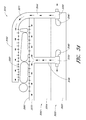
- FIG. 35 schematically illustrates a front view of a climate controlled bed assembly having wrap-around distribution layers according to one embodiment.
- This application is generally directed to climate control systems for beds or other seating assemblies.
- the climate control system and the various systems and features associated with it are described herein in the context of a bed assembly because they have particular utility in this context.
- the climate control system and the methods described herein, as well as their various systems and features can be used in other contexts as well, such as, for example, but without limitation, seat assemblies for automobiles, trains, planes, motorcycles, buses, other types of vehicles, wheelchairs, other types of medical chairs, beds and seating assemblies, sofas, task chairs, office chairs, other types of chairs and/or the like.
- spacers e.g., spacer fabrics or other materials
- comfort layers e.g., quilt layers
- sew seams stitching, hot melt barriers, engineered materials, flow diverters, passageways, inserts, fabrics and other impermeable members and/or the like, either alone or in combination with each other
- the arrangements disclosed herein can help reduce or minimize thermal losses as fluid is delivered to or from one or more occupants of a bed or other seating assembly. Thus, more uniform thermal coverage can be advantageously provided.
- climate-controlled beds and similar devices such as, for example, air chamber beds, adjustable beds, inner-spring beds, spring-free beds, memory foam beds, full foam beds, hospital beds, other medical beds, futons, sofas, reclining chairs, etc.
- climate control seating assemblies such as, for example, automobile or other vehicle seats, office chairs, sofas and/or the like.
- a bed 10 A can include a lower portion 20 (e.g., box spring, foundation, etc.) and an upper portion 40 (e.g., mattress).
- the lower portion 20 and upper portion 40 are separate members that are configured to be positioned adjacent to each other.
- the lower and upper portions 20 , 40 can be removably or permanently secured to each other using one or more connection devices or methods.
- the lower portion 20 can be configured like a box spring or other structure member for supporting the upper portion 40 positioned above it.
- two or more lower portions 20 can be used to support a single upper portion 40 .
- the bed 10 A can include more or fewer portions, layers, features and/or other members, as desired or required by a particular application or use.
- the bed 10 A can include a pillow-top portion (not shown) generally positioned along the upper surface of the top portion 20 .
- one or more intermediate layers are generally positioned between the lower portion 20 and the upper portion 40 .
- Such intermediate layers can be provided to reduce the likelihood of movement between the upper and lower portions 40 , 20 , to reduce fluid losses through the interface of the upper and lower portions or through retrograde fluid flow (e.g., downwardly, in the direction of the lower portion), to help maintain one or more components of the bed assembly at certain desired location and/or for any other purpose.
- the intermediate layer can extend continuously or substantially continuously between the upper and lower portions 40 , 20 .
- such an intermediate layer or member e.g., felt scrim
- the intermediate layer is secured to the upper portion 40 and/or the lower portion 20 using adhesives, fasteners and/or any other connection method or device, as desired or required.
- the lower portion 20 can include one or more fluid modules 100 that are adapted to provide temperate-conditioned (e.g., heated, cooled, etc.) air or other fluid to one or more portions of the bed 10 A.
- the bed 10 A comprises two fluid modules 100 .
- more or fewer fluid modules 100 can be included, as desired or required.
- the fluid modules 100 can selectively heat or cool air or other fluid that is being delivered through the bed 10 A toward one or more occupants.
- the fluid modules 100 can be configured to deliver ambient air or fluid toward or away from one or more occupants without performing any thermally conditioning at all.
- a climate control bed can include two or more separate zones, such that each zone can be selectively adjusted by an occupant, as desired or required.
- the fluid modules 100 can be configured to draw air or other fluids away from the top of the bed 10 A, either in lieu of or in addition to being configured to deliver fluids toward the top of the bed 10 A.
- the fluid module 100 can include a fluid transfer device 102 (e.g., blower, fan, etc.), a thermoelectric device or TED 106 (e.g., Peltier device), a convective heater, a heat pump, a dehumidifier and/or any other type of conditioning device, conduits to place the various components of the fluid module 100 and other portions of the bed 10 A in fluid communication with each other and/or the like.
- the lower portion 20 can include one or more inlets and outlets (not shown) through which air or other fluid can enter or exit an interior space 21 of the lower portion 20 .
- the fluid module 100 includes a heating, cooling and/or other conditioning (e.g., temperature, humidity, etc.) device that is not a thermoelectric device.
- a conditioning device can include a convective heater, a heat pump, a dehumidifier and/or the like. Additional information regarding convective heaters is provided in U.S. patent application Ser. No. 12/049,120, filed Mar. 14, 2008 and published as U.S. Publication No. 2008/0223841, and U.S. Provisional Patent Application No. 61/148,019, filed Jan. 29, 2009, the entireties of which are hereby incorporated by reference herein.
- a fluid module can be in fluid communication with one or more fluid conditioning devices, such as, for example, thermoelectric devices, convective heaters, heat pumps, dehumidifier units and/or the like.
- fluid conditioning devices such as, for example, thermoelectric devices, convective heaters, heat pumps, dehumidifier units and/or the like.
- Such devices can be incorporated into a fluid module, may be physically (e.g., directly or indirectly) or operatively attached to a fluid module and/or may simply be in fluid communication with a fluid module.
- a climate controlled bed assembly includes a dehumidifier unit that is configured to remove an undesirable amount of humidity from the air or other fluid being drawn into one or more inlets of the assembly's climate control system.
- thermoelectric device and/or any other thermal conditioning device
- a dehumidifier unit can be located within a fluid module.
- a dehumidifier can be placed upstream and/or downstream of the fluid module.
- a dehumidifier located upstream of the fluid module can help reduce the likelihood of potentially damaging and/or disruptive condensate formation within the thermoelectric device.
- the dehumidifier unit and/or any other conditioning devices can be positioned within the foundation (or lower portion of a bed), within the mattress (or upper portion of a bed) and/or at any other component or location, either within or outside the bed assembly. Additional information regarding condensate detection, removal and related concepts is provided in U.S.
- a waste fluid stream is typically generated.
- the waste fluid stream is generally hot relative to the main fluid stream, and vice versa. Accordingly, it may be desirable, in some arrangements, to channel such waste fluid out of the interior of the lower portion 20 .
- the waste fluid can be conveyed to one or more outlets (not shown) or other openings positioned along an outer surface of the lower portion 20 using a duct or other conduit. Additional details regarding such arrangements are provided herein with relation to FIGS. 15A-15C .
- the waste fluid streams from two or more of the thermoelectric devices may be combined in a single waste conduit.
- the upper portion 40 of the bed 10 A can include one or more types of core designs.
- the core 60 can comprise one or more foam portions, filler materials, springs, air chambers (e.g., as used in an air mattress) and/or the like.
- the upper portion 40 comprises a modified standard spring mattress. As illustrated in FIG.
- the core 60 comprises one or more fluid passageways 52 , openings or other conduits that are configured to place the lower portion 20 (e.g., the fluid modules 100 positioned within an interior space 21 of a box spring, other base or support structure, etc.) in fluid communication with the top of the upper portion 40 and/or any member, layers and/or portions 70 , 80 positioned above the core 60 (e.g., within one or more foam layers, between springs or other resilient members, etc.).
- the fluid passageways 52 can be positioned through an interior portion of the core 60 , as shown in FIG. 1A .
- one or more fluid passageways can be positioned along a side of the core and/or can be separate items from the core (e.g., configured to deliver air or other fluid around the core).
- the core 60 can comprise one or more fluid passageways 52 situated therein.
- the passageways 52 can be created after the core 60 has been completely or partially formed.
- the passageways 52 can include a generally cylindrical shape with a generally circular cross-section. In other embodiments, however, the passageways 52 can have a different cross-sectional shape, such as for example, oval, square, rectangular, other polygonal, irregular and/or like, as desired or required.
- air or other fluid is directly conveyed within the passageways 52 .
- the passageways 52 can be configured to accommodate an insert 54 ( FIGS. 7A and 14 ) through which fluids are transferred.
- Such inserts 54 can comprise one or more bellows or other features to help accommodate movement (e.g., compression, expansion, rotation, etc.) while the bed 10 A is in use.
- the inserts 54 can reduce the likelihood that air or other fluid being conveyed through the passageways 52 will be inadvertently directed to locations other that the intended target (e.g., pass through a space generally between the upper and lower portions 40 , 20 , leak into the core 60 or other portions or layers of the upper portion 40 , etc.) or pick up undesirable odors (e.g., from the surrounding foam, latex and/or other materials of the core 60 ) or other substances with which the air or other fluid may otherwise come in contact.
- the passageway 52 can include a liner (e.g., fabric liner), coating (e.g., liquid coating), film or other substance or member to help prevent or reduce the likelihood of air or other fluids from passing therethrough.
- a liner e.g., fabric liner
- coating e.g., liquid coating
- film or other substance or member to help prevent or reduce the likelihood of air or other fluids from passing therethrough.
- inserts 54 , liners, coatings, films and/or other features can help reduce the likelihood that air or other fluid will diffuse, penetrate or otherwise permeate to or from the core 60 , through the interior walls of the passageways 52 .
- the quantity, shape, size, location, spacing and/or other details regarding the passageways 52 can be different than illustrated and described herein, as desired or required by a particular application or use.
- the outlet of the fluid module (e.g., the blower, thermoelectric device or convective heater, etc.) is directly or indirectly connected to the insert or other duct that is configured to be routed through the passageway 52 or insert 54 .
- the interface of the passageway 52 (or one or more components positioned therein, e.g., an insert 54 ) and the fluid module can comprise a face seal, radial seal, mechanical attachment, coupling, another interface device and/or the like.
- each passageway 52 is adapted to be aligned and placed in fluid communication with a fluid module 100 .
- the lower portion 20 and the upper portion 40 can be configured so that the passageways 52 are generally aligned with the outlets or outlet conduits of one or more fluid modules 100 when the lower and upper portions 20 , 40 are secured to one another or otherwise placed in proper relation to each other. For example, as discussed with reference to FIGS.
- a fitting 38 , 38 ′ e.g., flange
- an interconnecting conduit 39 , 39 ′ and/or other interfacing member can be placed generally between the lower and upper portions 20 , 20 ′ and 40 , 40 ′ to ensure that the fluid modules 100 , 100 ′ are properly aligned (e.g., physically, hydraulically, etc.) with the corresponding passageways 52 , 52 ′ of the upper portion 40 , 40 ′.
- the use of protruding and/or recessed fittings or features on corresponding surfaces of the upper and lower portions of the bed can facilitate the alignment of the upper and lower portions.
- such fittings 38 , 39 , components and/or other devices can also help reduce the likelihood of relative movement between the lower and upper portions 20 , 40 , especially when the bed is in use.
- one or more intermediate members 37 ′ can be positioned generally between the upper and lower portions of a climate control bed assembly.
- the intermediate member 37 ′ includes a generally circular felt scrim or other layer having a central opening.
- the felt scrim or member 37 ′ is approximately 2 mm thick and 155 mm (6.1 inches) in diameter.
- the intermediate member 37 ′ can include a central opening, which, in some embodiments, is shaped and sized to generally match the opening size of the adjacent components of the climate control bed (e.g., the flange 38 ′, the interconnecting conduit 39 ′, the insert 54 ′ positioned within the passageway 52 ′, etc.).
- the shape, size and other characteristics of the intermediate member 37 ′ can vary, as desired or required.
- the intermediate member 37 ′ can be configured to secure to an adjacent surface of the upper portion and/or the lower portion of the bed assembly using adhesives (e.g., adhesive strip), fasteners and/or any other connection device or method.
- an intermediate member 37 ′ can help maintain the position of the lower end (e.g., flanged end) of the insert 54 ′ during use, thereby preventing undesirable pull-through of the insert 54 ′ into the passageway 52 ′.
- an intermediate member 37 ′ can help reduce the likelihood of leaks as conditioned and/or unconditioned air or other fluid is conveyed from a fluid module toward an occupant.
- the intermediate member 37 ′ can be configured to prevent or substantially prevent conditioned air from flowing backwards through the insert toward the interface between the upper and lower portions of the bed assembly.
- a felt scrim 37 ′ or other intermediate member can be included with any embodiment of a climate controlled bed assembly disclosed herein or equivalents thereof.
- one or more members 70 , 80 , layers and/or portions can be positioned on top of the upper portion 40 of the bed 10 A or incorporated as layers along the top end of the upper portion 40 .
- the depicted embodiment includes a fluid distribution member 70 comprising a spacer (e.g., spacer fabric) or other material configured to generally distribute fluid (e.g., open cell foam, a member having an open lattice structure, a spacer or other material placed within a bag or other enclosure, etc.).
- a fluid distribution member can include one or more channels or other conduits through which fluids may be directed.
- Such channels or other conduits can be configured to distribute air or other fluid to selected portions of the fluid distribution member, and thus, the bed assembly.
- the channels or other conduits can be formed when the fluid distribution member is being manufactured (e.g., using injection molding, other molding technologies, etc.). Alternatively, the channels or other conduits can be formed after the fluid distribution member has been completed, using one or more forming devices or methods.
- the upper portion 40 can be configured for any type of bed, including, without limitation, air chamber beds, adjustable beds, inner-spring beds, spring-free beds, memory foam beds, full foam beds, hospital beds, other medical beds, futons, sofas, reclining chairs and/or the like.
- air or other fluids delivered into such a fluid distribution member 70 from the passageways 52 may be partially or completely dispersed throughout the fluid distribution member 70 . This can help ensure that fluid being delivered by the fluid modules 100 is generally distributed throughout a desired top surface area of the bed 10 A.
- the bed 10 A can also include a comfort layer 80 (e.g., quilt layer) or other layer or member that is generally configured to enhance an occupant's comfort.
- a comfort layer 80 is configured to permit fluids to pass through it.
- a comfort layer 80 such as used in any the embodiments disclosed herein or equivalents thereof, is configured to allow air or other fluids to pass therethrough only when a threshold back-pressure applied to it has been achieved.
- the terms comfort layer and quilt layer are used interchangeably herein.
- a comfort layer 80 may comprise a desired back-pressure range for a given fluid flowrate.
- the back-pressure measured at the fluid module (e.g., the blower or other fluid transfer device), can be less than 1 inch of water when the fluid flowrate is 10 scfm.
- such a maximum back-pressure can be higher or less than 1 inch of water (e.g., less than 0.01, 0.05, 0.1, 0.2, 0.3, 0.4, 0.5, 0.6, 0.7, 0.8, 0.9, 1.1, 1.5, 2.0, 5.0, 10.0, more than 10.0 inch water, ranges between such values, etc.).
- the target back-pressure range can depend on one or more factors or considerations, such as, for example, the friction losses through fluid passageways, fittings and other hydraulic components, the types of materials that comprise the various components of the bed, the shape, size and other properties of the various bed components or layers, the types of spacers (e.g., spacer fabric) utilized and/or the like.
- Limiting the back-pressure and/or fluid flowrate through a comfort layer and/or other components or layers of a climate controlled bed assembly can provide certain advantages. For example, such limitations can ensure a proper feel at the exposed top surfaces of the bed assembly to generally improve the comfort level of an occupant. In addition, such limitations can help reduce the noise created by air or other fluids moving through the climate control bed. In other embodiments, such limitations can help conserve power and lower the operational expenses of the bed assembly. Additional disclosure about noise and vibration abatement features for climate control bed assemblies is provided below.
- ambient or thermally conditioned fluid once ambient or thermally conditioned fluid has been delivered into the fluid distribution member 70 , it can be directed toward the top surface of the bed 10 A through the comfort layer 80 .
- one or more other layers 68 or members can be selectively included in the upper portion 40 of the bed (e.g., between the core 60 and the bed's top surface).
- the bed 10 B further comprises one or more flow diversion members 74 generally positioned above the passageways 52 of the core 60 or other location of the bed's upper portion 40 .
- flow diversion members or diverters 74 can help distribute air or other fluid that is directed into the fluid distribution member 70 (e.g., spacer fabric or other material).
- the flow diversion members 74 can be positioned above the fluid distribution member (e.g., between the fluid distribution member 70 and the comfort layer 80 ).
- the flow diversion members 74 can be sized, shaped and otherwise configured to create a desired air flow dispersion pattern within a desired portion of the fluid distribution member 70 .
- the flow diversion members 74 can comprise one or more air impermeable, semi-permeable or permeable materials, as desired or required. For instance, even if some fluid is permitted to pass through the flow diversion members 74 , the mere presence of the diversion members 74 above the passageways 52 of the core 60 can cause air or other fluid to be deflected in a lateral or generally lateral direction.
- the terms flow diversion member and flow diverter are used interchangeably herein.
- FIG. 2 schematically illustrates a cross-sectional view of another embodiment of a climate-controlled bed 10 C.
- the depicted bed 10 C is similar to the arrangements illustrated in FIGS. 1A and 1B and discussed herein, except that it comprises an additional comfort layer 68 or other member between the fluid distribution member 70 and the core 60 .
- This additional comfort layer 68 or member can be separate from the core 60 or can form a unitary structure with the core 60 .
- the additional comfort layer 68 can be configured to further enhance the comfort level to a bed occupant.
- the additional comfort layer 68 comprises foam (e.g., viscoelastic foam, polyurethane foam, memory foam, other thermoplastics or cushioning materials and/or the like).
- the additional comfort layer 68 can comprise conduits 69 that generally align and are in fluid communication with the passageways 52 of the core 60 .
- the additional comfort layer 68 forms a unitary structure with the core 60 .
- the additional comfort layer 68 is a separate item from the core 60 that may be attached to it using adhesives, stitching, fasteners and/or any other connection device or method.
- air or other fluid can be conveyed through the passageways 52 of the core 60 and the conduits 69 of the additional comfort layer 68 toward the fluid distribution member 70 .
- air and/or other fluids can be at least partially laterally dispersed (e.g., with or without the help of flow diversion members 74 ) before exiting toward the top of the bed assembly 10 C (e.g., through one or more comfort layers 80 , other layers or components, etc.).
- an air impermeable or substantially air impermeable film 71 , layer or other member is generally situated below the fluid distribution member 70 . This can help prevent or reduce the likelihood of air or other fluids from being undesirably conveyed from the fluid distribution member 70 toward the additional comfort layer 68 and the core 60 . In other embodiments, such a film 71 is less air permeable than the comfort layer 80 or other layers positioned on top of the fluid distribution member 70 .
- the film 71 or other layer can be used in any of the embodiments disclosed herein or equivalents thereof.
- the additional comfort layer 68 A includes a plurality of openings 67 A that are configured to extend completely or partially through the depth of the additional comfort layer 68 A.
- a perforated additional comfort layer 68 A is positioned adjacent to a core 60 , at least some of the openings 67 A can be placed in fluid communication with the passageways 52 of the core.
- the openings 67 A can permit air or other fluid to be conveyed from the passageways 52 of the core 60 to the fluid distribution member 70 situated above the additional comfort layer 68 A.
- This can advantageously simplify the design of the additional comfort layer 68 A as the need to align the conduits 69 ( FIG. 2 ) of the additional comfort layer with the passageways 52 of the core 60 can be eliminated.
- a perforated additional comfort layer 68 can be used with cores having different passageway sizes, locations, spacing, orientations and/or other characteristics.
- the bed's upper portion 40 can include one or more other layers or members, either in addition to or in lieu of any of the layers or members illustrated or discussed in connection with the various embodiments disclosed herein. Adjacent layers or members of the bed can be attached to each other using one or more connection methods or devices, such as, for example, adhesives, stitching, seams, fasteners and/or the like.
- connection methods or devices such as, for example, adhesives, stitching, seams, fasteners and/or the like.
- the size, thickness, shape, materials and/or other details of the various layers or members included in the bed can vary, as desired or required by a particular application or use.
- the lower portion 20 can include a lower frame 22 and an upper frame structure 24 .
- the lower frame 22 includes relatively large, rigid members (e.g., wood, steel, composites, etc.) that generally form the lower end of the bed.
- the upper frame structure 24 can include a plurality of smaller metal members that are shaped to form a three-dimensional structure. In some arrangements, the upper frame structure 24 is configured to resiliently support a core and other components of the upper portion 40 .
- one or more fluid modules 100 can be positioned within an interior of the lower portion 20 .
- the depicted embodiment comprises two fluid modules 100 ; however, more or fewer fluid modules 100 can be included, as desired or required.
- the fluid modules 100 can be electrically connected to a controller 16 (e.g., control unit) using one or more hardwired and/or wireless connections. As shown, power and control wires extending to and/or from each fluid module 100 can be routed through electrical conduits 18 or other enclosures.
- the fluid modules, controllers and/or any other components or portions of the climate control system can be positioned outside the lower portion 20 and/or any other portion of the bed.
- the lower portion 20 can include a covering material 30 along an exterior area.
- a covering material 30 can be placed along other areas of the lower portion 20 .
- the entire exterior surface of the lower portion 20 can include a covering material 30 .
- the covering material 30 can comprise a fabric, a film and/or the like.
- at least a part of the top of the lower portion 20 comprises a covering material 30 that is configured to help reduce movement between the lower portion 20 and the adjacent upper portion (e.g., core).
- the covering material 30 can include a non-skid or substantially non-skid surface texture or features (e.g., bumps, grooves, etc.).
- the covering material can comprise one or more non-skid materials (e.g., rubber).
- the covering material 30 can include one or more openings 34 that are generally aligned with the fluid modules 100 positioned within the lower portion 20 .
- the fluid modules 100 can be secured to one or more areas of the lower portion 20 .
- the fluid module 100 includes supports 108 A, 108 B or other portions or features that are adapted to secure to the frame structure 24 .
- the support 108 A, 108 B or any other portion of the fluid modules 100 can be secured to any other area of the lower portion 20 .
- a fluid module 100 can be secured to the lower portion 20 of a bed using any other device or method. In other embodiments, as discussed herein with reference to FIG.
- the lower portion 20 ′ includes a backer board 110 to which one or more components (e.g., fluid module 100 ′, power supply 112 ′, control unit 114 ′, humidity sensor 116 ′, other types of sensors, etc.) of the climate control bed assembly 10 ′ are configured to secure. Additional details regarding such an embodiment are provided below.
- one or more components e.g., fluid module 100 ′, power supply 112 ′, control unit 114 ′, humidity sensor 116 ′, other types of sensors, etc.
- air or other fluid can enter the fluid modules 100 through one or more vents or other openings (not shown) located along the lower portion 20 of the bed assembly.
- any waste air or fluid exiting the fluid modules 100 can be directed out of an interior of the lower portion 20 through one or more vents or openings (not shown).
- air or other fluids enter into or exit from the interior of the lower portion 20 of the bed through an air permeable layer (e.g., a fabric or other covering material 30 , as discussed herein) and/or any other member.
- an air permeable layer e.g., a fabric or other covering material 30 , as discussed herein
- a foundation or lower portion 120 of a climate controlled bed assembly can be configured to include separate thermal zones for keeping the fluid module's main conduits generally separate from its waste conduits.
- the bottom portion includes a specially-designed bed skirt 140 to further assist in preserving such thermally-separated zones intact. Additional information regarding such arrangements is provided below.
- FIG. 5 illustrates an upper portion 40 of a bed 10 positioned on top of a lower portion 20 .
- the lower portion 20 can include a frame 22 and a frame structure 24 generally positioned on top of the frame 22 .
- the lower portion 20 can include a plurality of legs 26 or other support members.
- one or more of the legs 26 or other support members comprise wheels to facilitate moving the bed 10 relative to the floor.
- the upper portion 40 of the bed can include a core 60 and one or more layers or portions 70 , 80 positioned thereon.
- a flow conditioning member 70 e.g., a spacer or other material
- a comfort layer 80 e.g., a quilt layer
- flow diversion members 74 and/or any other layer or member can be positioned on top of the core 60 , as desired or required by a particular application.
- the upper portion 40 comprises the general structure and characteristics of an inner-spring bed, an air chamber bed, an adjustable bed, a spring-free bed, a memory foam bed, a full foam bed, a hospital bed, another type of medical bed, a futon, a sofa, a reclining chair and/or the like.
- the arrangement depicted in FIG. 5 further comprises a user interface device 12 (e.g., a handheld controller) that is operatively connected (e.g., hardwired, wirelessly, etc.) to the fluid modules 100 , a main control unit and/or any other component or device used to operate the bed 10 .
- FIG. 6 illustrates an exploded view of the bed 10 of FIG. 5 .
- the foundation or lower portion 20 can include a covering material 30 or other layer along its top surface that is configured to contact the upper portion 40 (e.g., core 60 ).
- the fluid modules 100 positioned within an interior of the lower portion 20 can be placed in fluid communication with passageways 52 ( FIG. 7A ) of the core 60 through one or more openings 34 in the covering material.
- One or more fittings 38 or other devices can be optionally used to help place the fluid modules 100 in fluid communication with the passageways 52 .
- such fittings 38 can help ensure that the upper portion 40 (e.g., the core 60 ) does not slide or otherwise move relative to the lower portion 20 . Additional information regarding such fittings and other devices positioned at the interface of the upper and lower portions 40 , 20 is provided herein with reference to FIG. 14 .
- each of the passageways 52 of the core 60 can include an insert 54 .
- air or other fluid can be conveyed through the passageways 52 either partially or entirely within such inserts 54 .
- this can help reduce the likelihood that air or other fluid will diffuse through the walls of the passageways 52 into the core 60 or other portions of mattress 40 or upper portion of the bed assembly.
- the inserts 54 can help prevent air or other fluid being conveyed therein from picking up undesirable odors as it is being conveyed toward the fluid distribution member 70 , the comfort layer 80 and/or any other portion positioned along the top of the upper portion 40 .
- the inserts 54 can include bellows or other features that help the inserts 54 flex, compress, stretch and/or otherwise move in response to one or more loads, moments, stresses or other forces imparted on the bed 10 .
- the inserts 54 and/or any fittings 38 to which the inserts 54 are connected can include flanges or other protruding features that are configured to contact adjacent surfaces of the core 60 , fluid distribution member 70 , the lower portion 20 and/or any other component of the bed. The use of such flanges or other features can help secure the inserts 54 and/or fittings 38 relative to the passageways 52 of the core 60 , and thereby reduce the likelihood of fluid leaks, pull-through of the insert 54 and/or any other undesirable occurrence.
- the core 60 can include one or more layers 62 , 64 , 66 , 68 or portions.
- the core 60 comprises a main foam portion 62 positioned along the lower part of the core 60 .
- the core 60 comprises a plurality of innersprings or coils, either in lieu of or in addition to foam and/or other filler materials.
- the core 60 can have one or more upper layers 64 , 66 , 68 that may comprise one or more other types of foam or other materials.
- the use of different foams or other materials can permit a bed 10 to be manufactured with certain properties (e.g., rigidity, flexibility, comfort, resiliency, etc.), as desired or required.
- the different layers 62 , 64 , 66 , 68 of the core 60 can comprise high performance foam, viscoelastic foam, memory foam, open-cell foam, closed-cell foam, other types of foam, filler materials, other natural or synthetic materials, spring coils and/or the like.
- the core comprises one, two, three or more layers of latex, viscoelastic foam or other viscoelastic materials.
- the core can comprise air chambers, springs and/or any other types of components or features, as desired or required.
- the layers 64 , 66 , 68 positioned on top of the main core layer 62 can comprise a high-performance foam, a viscoelastic foam and a soft foam, respectively.
- a core 60 can include different materials (e.g., filler materials, thermoplastics, air chambers, springs, other natural or synthetic materials, etc.), either in lieu of or in addition to foam.
- the core can include more or fewer portions, layers and/or materials than disclosed herein. In arrangements where the core 60 comprises two or more portions or layers, such portions or layers can be attached to one another using adhesives, stitching, fasteners and/or any other device or method. For example, in one embodiment, the various layers of the core 60 are hot melted to each other.
- ambient and/or thermally-conditioned air or other fluid can enter one or more fluid distribution layers 70 .
- one or more flow diversion members 74 or diverters strategically positioned above the fluid distribution layer 70 can help re-direct at least some of the air or other fluid entering the fluid distribution layer 70 in a lateral or substantially lateral direction. This can help promote a more even flow distribution and dispersion within the fluid distribution member 70 .
- the flow diverters 74 can comprise one or more materials, such as, for example, polymeric materials, fabrics and/or the like.
- the flow diversion members 74 are configured to allow at least some air or fluid to permeate therethrough.
- the flow diversion members 74 can be non air-permeable or substantially non air-permeable, as desired or required.
- the flow diversion members 74 can be attached to the fluid distribution member 70 and/or one or more adjacent layers of a bed assembly 10 using adhesives, stitching and/or any other connection device or method.
- the quantity, size, shape, orientation and/or other details of the fluid distribution member 70 and/or the flow diverters 74 can vary, as desired or required.
- a bed comprises no flow diversion members 74 .
- one or more other layers or members can be positioned between the fluid distribution member 70 and the flow diversion member 74 .
- one or more comfort layers 80 can be positioned above and/or below the fluid distribution member 70 .
- the comfort layer 80 comprises one or more soft materials, such as, open-cell foam, memory foam, other soft foam, down feathers, other natural or synthetic filler materials and/or the like.
- Such a comfort layer 80 can be air-permeable so that air or other fluids exiting the top of the fluid distribution member 70 can be transmitted therethrough.
- the thickness, size, orientation relative to other layers of the bed, materials of construction and/or other characteristics of the comfort layer 80 can vary, as desired or required.
- the various layers or components that are included in the upper portion 40 of the bed can be attached to each other using adhesives, stitching and/or any other device or methods.
- one or more components or layers of the upper portion 40 can be configured to be separate or separable from each other.
- FIGS. 8A and 8B schematically illustrate one embodiment of an upper portion 240 of a climate controlled bed assembly 210 having certain features, components and advantages as described herein.
- the upper portion 240 comprises a core 260 which includes four internal passageways 252 across its depth.
- the passageways 252 can have a generally cylindrical shape.
- the passageways 252 can include any other desired or required cross-sectional shape, such as, for example, square, rectangular, triangular, other polygonal, oval, irregular and/or the like.
- the passageways 252 are symmetrically arranged along the core 260 . This can allow the upper portion 240 to be rotated relative to the lower portion (not shown in FIGS.
- the passageways 252 of the core 260 can include a non-symmetrical orientation.
- the core 260 can include more or fewer than four internal passageways 252 , as desired or required by a particular application or use.
- the size, shape, spacing, orientation and/or any other details of the passageways 252 and/or the core 260 can be different than illustrated or discussed herein.
- the number of internal passageways 252 included in an upper portion of a thermally-conditioned bed can be selected based on the various independently-controlled zones that such a bed comprises. Additional disclosure regarding such arrangements is provided herein in relation to FIGS. 8A-11D, 31 and 32 .
- the core 260 can comprise one or more materials or components, such as, for example, foam, other thermoplastics, air chambers, coil springs, other resilient members, filler materials and/or the like.
- the upper portion 240 can be configured to be selectively positioned on a lower portion (e.g., foundation, box spring, other frame, etc.).
- the passageways 252 of the core 260 can be configured to generally align with openings in the lower portion so as to place the passageways 252 in fluid communication with one or more fluid modules (e.g., fans, blowers or other fluid transfer devices, thermoelectric devices, convective heaters or other temperature-conditioning devices, etc.).
- one or more fluid modules e.g., fans, blowers or other fluid transfer devices, thermoelectric devices, convective heaters or other temperature-conditioning devices, etc.
- ambient or thermally-conditioned air or other fluid can be advantageously conveyed through the passageways 252 and through one or more layers or components situated above the core 260 , toward the top surface of the upper portion.
- air or other fluid can be directed from the passageways 252 into a fluid distribution member 270 (e.g., spacer material, spacer fabric or other material) or any other member that is generally configured to laterally or substantially laterally distribute fluid (e.g., air) within the interior of the bed, so that such fluid is advantageously directed along a desired top surface of the bed 210 .
- a fluid distribution member 270 e.g., spacer material, spacer fabric or other material
- air or other fluid can pass through one or more layers or members located along the top of the bed 210 .
- the upper portion 240 comprises a comfort layer 280 (e.g., quilt layer) that is adapted to allow air or other fluid to diffuse therethrough.
- the top portion 240 (e.g., mattress) can comprise one or more other comfort layers, fluid distribution members, filler materials, coil springs or other resilient member and/or the like, to achieve a desired feel (e.g., firmness), comfort level, fluid distribution scheme or the like.
- FIGS. 9A and 9B Another embodiment of a climate controlled bed assembly 310 is schematically illustrated in FIGS. 9A and 9B .
- the depicted bed 310 is similar to the one illustrated and described herein with reference to FIGS. 8A and 8B .
- the upper portion 340 of the bed 310 in FIGS. 9A and 9B additionally includes flow diversion members 374 or diverters above each of the fluid passageways 52 .
- the flow diversion members 374 comprise a circular shape and are positioned between the fluid distribution member 370 (e.g., spacer, spacer fabric or material, etc.) and a comfort layer 380 (e.g., quilt layer).
- such flow diverters 374 can help at least partially deflect air or other fluid entering the fluid distribution member 370 in a generally lateral direction. Accordingly, the air or other fluid can be more evenly distributed within the fluid distribution member 370 before it exits toward the comfort layer 380 and/or other top layers of the bed 310 . As discussed herein with respect to other embodiments, the flow diversion members 374 can be air permeable, partially air-permeable or non-air permeable, as desired or required.
- the upper portion 440 can be divided into two or more different climate control zones 442 , 444 or areas.
- the climate control bed assembly 410 can be configured to separately cool and/or heat each zone 442 , 444 according to the preferences of its occupant(s). For example, under such an arrangement, if two people are positioned on the bed 410 , each person can separately control the level of heating, cooling and/or ventilation occurring along his or her side of the bed 410 . Thus, in some embodiments, one user heats his or her side of the bed, while another occupant simultaneously cools or ventilates his or her side of the bed. In other arrangements, both users can heat (or cool or ventilate) their respective sides of the bed, but to varying extents.
- separate heating and/or cooling zones 442 , 444 can be created using sew seams, engineered stitching, other types of stitching, glue beads and/or similar features 476 .
- sew seams, stitching or glue beads can be used to partially, completely or substantially completely maintain fluid flow within certain portions or areas of the fluid distribution member 470 .
- air or other fluid from one zone 442 , 444 is generally not permitted to enter an adjacent zone 442 , 444 .
- one or more fluid distribution members can be generally bounded or otherwise framed by a layer or portion that is air-impermeable or substantially air-impermeable. Accordingly, air or other fluid entering such a fluid distribution member is generally not permitted to be laterally conveyed past a particular outer border.
- the individual climate-control zones or areas 442 , 444 created by the sew seams 476 , stitching, beads or the like are sized to cover most of the area of the bed 410 .
- the area over which the zones 442 , 444 extend can be larger or smaller than illustrated in FIGS. 10A and 10B , as desired or required.
- a bed 410 can include more or fewer zones or areas 442 , 444 .
- air or other fluid is supplied to each zone 442 , 444 by two passageways 452 in the core 460 .
- passageways 452 can be associated (e.g., in fluid communication) with each zone or area 442 , 444 .
- one or more of the passageways 452 may be separate from the core 460 and/or may be positioned along the outside of or generally around a core 460 .
- Air or other fluid can diffuse within the fluid distribution member 470 generally up to the outer limits formed by the seams or beads 476 (or any other fluid barrier, such as, for example, an outer frame as illustrated in FIGS. 11A-11D ).
- the sew seams, stitching, beads 476 or any other barrier are configured to allow some fluid to cross into an adjacent zone or area 442 , 444 .
- the seams, stitching, beads or other flow blocking features 476 of the fluid distribution member 470 may be configured to not completely prevent air or other fluids from traversing across the boundaries they generally form.
- the fluid distribution member 470 can be configured to prevent or substantially prevent fluid flow across a particular seam, stitching, bead and/or other flow blocking device or feature 476 . This can be especially important for the sew seams, stitching or beads 476 near the middle of the fluid distribution member 470 that separate adjacent zones 442 , 444 .
- a flow diversion member 474 or diverter can be generally positioned above each fluid passageway 452 of the core 460 .
- a more even distribution of air can be achieved both within and out of each zone or area 442 , 444 .
- air exiting the top of each zone 442 , 444 of the fluid distribution member 470 can be directed to and through one or more top layers 480 (e.g., quilt layer, other comfort layer, etc.).
- an upper portion of a climate controlled bed can include one or more sew seams, stitches, glue seams, borders and/or the like.
- such features can help direct ambient and/or thermally-conditioned fluids to one or more target regions of the bed assembly.
- a user is permitted to selectively control the cooling, heating and/or ventilation effect being provided to his or her portion of the bed assembly.
- a bed assembly can be selectively operated under one or more desired operational schemes.
- Such schemes can be based, at least in part, on a timer, one or more sensors (e.g., pressure sensors, temperature sensors, humidity sensors, etc.) and/or the like.
- sensors e.g., pressure sensors, temperature sensors, humidity sensors, etc.
- Such operational schemes can help conserve power, enhance comfort to an occupant and/or provide other advantages.
- the bed can be operated according to a desired operational scheme (e.g., with the temperature and/or flowrate of the fluid being delivered to or from an occupant varying based on the passage of time or some other condition).
- the bed assembly is operated to maintain a desired temperature or feel along a top surface on which one or more occupants are situated.
- the bed can include one or more sensors (e.g., temperature sensors, humidity sensors, other sensors that are configured to detect a fluid property, etc.), a controller, a timer, a user input device and/or the like.
- sensors e.g., temperature sensors, humidity sensors, other sensors that are configured to detect a fluid property, etc.
- FIGS. 11A-11D illustrate another embodiment of an upper portion 540 of a climate controlled bed 510 having separate heating, cooling and/or ventilation zones 542 , 544 .
- the depicted upper portion 540 comprises a core 560 , a fluid distribution member 570 and a comfort layer 580 .
- the upper portion 540 can include more or fewer layers or portions and/or completely different layers or portions.
- the layers or portions can be differently arranged (e.g., the vertical order), as desired or required.
- the fluid distribution member 570 can include a base portion 572 or frame that is configured to be non-air permeable or substantially non-air permeable, especially when compared to the adjacent inlay portions that comprise the climate control zones or areas 542 , 544 .
- the base portion 572 comprises closed cell foam and/or any other material having relatively high back pressure properties (e.g., dense foam, other types of foam, fabric, film, etc.).
- the fluid distribution member 570 can include one, two or more openings or recesses along its top surface into which inlay portions or members 574 may be positioned.
- the inlay portions 574 can include a spacer (e.g., spacer fabric) and/or other air-permeable material that is configured to help distribute air within the recess of the base portion 572 .
- the inlay portions or members 574 are sized, shaped and otherwise configured to snugly or substantially snugly fit within the recesses of the base portion 572 .
- the inlay portions or members 574 can extend across only a portion of the recesses.
- the inlay portions or members 574 can be secured to the base portion 572 using adhesives, fasteners and/or any other device or method.
- the recesses extend only partially through the depth of the fluid distribution member 570 .
- the recesses extend across the entire depth of the fluid distribution member 570 .
- the inlay portions or members 574 can be configured to have substantially the same depth or thickness as the fluid distribution member 570 into which they are secured.
- the fluid distribution member 570 additionally comprises a carrier layer 576 (e.g., fabric, film, etc.) or other member along its bottom surface.
- a carrier layer 576 e.g., fabric, film, etc.
- Such a carrier layer 576 can be air impermeable or substantially air impermeable, and thus, help prevent or reduce the likelihood of air or other fluid from undesirably escaping the upper portion 540 through the bottom of the fluid distribution member 570 .
- the base portion 572 and/or the carrier layer 576 can include one or more openings 578 through which air or other fluid being conveyed into the inlay portions 574 of the fluid distribution member 570 may pass.
- the recesses extend through the entire depth of the fluid distribution member 570 , such openings 578 may not be present.
- air or other fluid can diffuse laterally within some or all of the fluid distribution member, before being directed toward and through one or more layers positioned above the fluid distribution member 570 .
- the air or other fluid passes through a comfort layer 580 before exiting the top the bed 510 .
- the upper portion 540 can include additional comfort layers and/or any other layers or members. Such additional layers or members can be positioned above and/or below the fluid distribution member 570 , as desired or required.
- the outer frame or border created by the shape of the base portion 572 can help confine air or fluid within a specific inlay portion 574 , and thus, a target area of the bed.
- a bed 510 can advantageously include one, two or more separate climate control zones 542 , 544 , allowing a user to selectively heat, cool and/or ventilate one or more areas of the bed 510 according to his or her own preferences.
- Each zone 542 , 544 can be in fluid communication with one or more fluid modules (e.g., fan, blower, other fluid transfer device, thermoelectric device, convective heater, etc.).
- the fluid modules can be positioned within or otherwise incorporated into an interior space of a foundation or other lower portion of the bed.
- the fluid modules can be positioned within or otherwise incorporated into an interior space of a foundation or other lower portion of the bed.
- the various components of a climate control system can be secured to a backer board 110 or other rigid or semi-rigid surface of the foundation).
- a backer board 110 or other rigid or semi-rigid surface of the foundation.
- Such integration of the various climate control components of a bed assembly can provide certain advantages, including, without limitation, facilitating manufacture, shipping, assembly and installation, reducing costs, simplifying the overall design of the system and/or the like.
- each climate control zone 542 , 544 can be advantageously configured to receive thermally-conditioned and/or ambient air or other fluid from one, two or more different fluid modules (e.g., a blower or other fluid transfer device, a thermoelectric device, a convective heater, etc.), as desired or required.
- a fluid module can be adapted to provide ambient and/or thermally conditioned air or other fluid to one, two or more different zones 542 , 544 of a bed.
- a bed 510 can include a total of four passageways 552 that are routed through an interior portion of the core 560 .
- each inlay portion 574 e.g., spacer, spacer fabric or other material
- an inlay portion 574 can be in fluid communication with more or fewer passageways 552 .
- air or other fluid can be directed to a fluid distribution member 570 ′ using one or more exterior passageways 552 ′.
- an externally routed passageway 552 ′ can be used to place each inlay portion 574 ′ (e.g., spacer, spacer fabric or other material, etc.) of the fluid distribution member 570 ′ in fluid communication with one or more fluid modules (not illustrated).
- Such configurations help eliminate the need for passageways that are routed through an interior of the core 560 ′ or other region of the upper portion 540 ′. As a result, the manufacture, assembly and/or other activities related to providing a climate controlled bed assembly can be simplified.
- a separate external passageway 552 ′ is used to deliver ambient and/or thermally conditioned fluid to each inlay portion 574 ′.
- a passageway 552 ′ can be configured to supply air or other fluid to two or more different inlays 574 ′ or other portions of the bed 510 ′.
- two or more passageways 552 ′ can be placed in fluid communication with a single inlay 574 ′.
- the upper portion 540 ′ depicted in FIG. 11E can include one or more other layers (e.g., quilt or comfort layer 580 ′) positioned above and/or below the fluid distribution member 570 ′.
- a climate controlled bed assembly can include a fluid distribution member that comprises one or more internal channels or other conduits through which air or other fluid may be directed. This can help distribute fluids to one or more desired portions of the bed assembly.
- FIG. 12A One embodiment of a climate controlled bed 610 A having such a fluid distribution member 670 A is schematically illustrated in FIG. 12A .
- the fluid distribution member 670 A can include an inlet 678 A that is in fluid communication with one or more channels 674 A, recesses or other areas within the fluid distribution member 670 A through which fluids may pass.
- the fluid distribution member 670 A comprises a plurality of openings 675 A that are in fluid communication with the internal channels 674 A.
- air or other fluids delivered through the inlet 678 A and the channels 674 A can be distributed toward the top of the bed (e.g., through a quilt or comfort layer 680 A, other layers or portions of a mattress, etc.).
- the quantity, shape, size, location, spacing and other details of the inlet 678 A, channels 674 A, openings 675 A and/or any other portion of the fluid distribution member 670 A can vary, as desired or required by a particular application or use.
- a spacer e.g., a spacer fabric
- other generally flow permeable material can be positioned within one or more locations of the channels 674 A and/or other portion of the fluid distribution member 670 A.
- an insert, liner, film or other material can be positioned along the channels 674 A or any other portion of the fluid distribution member 670 A.
- Such inserts can help reduce or prevent fluid losses across the main portion 672 A of the fluid distribution member 670 A.
- members or components can help to structurally reinforce the internal channels and other passageways of the fluid distribution member 670 A, especially when the bed 610 A is being used.
- the size and shape of the passageways can be generally maintained to allow air or other fluids to pass therethrough.
- the fluid distribution member 670 B can include a fluid inlet 678 B and one or more recessed areas 674 B.
- a spacer 676 B e.g., a spacer fabric, other air permeable material or member, etc.
- the spacer 676 B can help to structurally reinforce the recessed area 674 B.
- the spacer 676 B can help ensure that air or other fluids are more evenly distributed to one or more desired portions of the fluid distribution member 670 B.
- the recessed area 674 B or other portion of the fluid distribution member 670 B can include an insert, liner, film or other member.
- Air or other fluid entering the inlet 678 B can be distributed (e.g., vertically, laterally, etc.) through the spacer 676 B. Once it exits through the top of the fluid distribution member 670 B, the air or other fluid can be directed toward the top of the bed assembly 610 B through one or more layers or members (e.g., a comfort layer 680 B).
- FIG. 12C illustrates an exploded cross-sectional view of another embodiment of an upper portion 640 C for a climate controlled bed 610 C.
- the upper portion 640 C can include a core 660 C having one or more internal passageways 652 C.
- the core 660 C comprises only a single passageway 652 C.
- the core may include two, three or more passageways 652 C, as desired or required by a particular application.
- the upper portion 640 C can further include a fluid distribution member 670 C and one or more other layers 680 C (e.g., comfort layer) positioned on top of the core 660 C.
- the fluid distribution member 670 C can include a spacer 674 C and/or other air-permeable portion that is configured to more evenly distribute air or other fluid throughout the member 670 C.
- the spacer 674 C e.g., spacer fabric or other material
- the air impermeable layer 672 C can comprise a woven fabric, another type of fabric, a film, a laminate, a bag, other enclosure and/or the like.
- two openings 676 C in the air impermeable layer 672 C extend generally along the top surface of the fluid distribution member 670 C.
- air or other fluid entering the fluid distribution member 670 C e.g., through one or more bottom inlets 678 C
- Air or other fluid can exit the interior of the fluid distribution member 670 C toward one or more top layers (e.g., a quilt or comfort layer 680 C, additional fluid distribution members, other layers or members, etc.) through one or more openings 676 C of the air impermeable layer 672 C.
- air or other fluid can be delivered to the fluid distribution member 670 C through one or more external passageways (not shown in FIG. 12C ), either in lieu of or in addition to an internal passageway 652 C.
- FIG. 13A illustrates an embodiment of a climate controlled bed assembly 710 A that includes a top member 790 A that is adapted to be positioned on top of a core 760 A.
- the top member 790 A comprises a fluid distribution portion 792 A (e.g., a spacer, spacer fabric or other material, etc.), a bottom interface layer 796 A and a top comfort layer 794 A.
- the bottom interface layer 796 A can comprise foam or another generally cushioned material that is configured to enhance the comfort level of an occupant.
- the various layers and/or components of the top member 790 A are configured to be joined together as a unitary structure.
- the fluid distribution portion 792 A, the bottom interface layer 796 A and the top comfort layer 794 A can be secured to each other using adhesives, stitching, staples, other fasteners and/or any other device or method.
- the top member 790 A can be collectively attached to a core 760 A to facilitate assembly of the upper portion 740 A.
- the top member 790 A is configured to be fluid communication with one or more passageways 752 A of the core 760 A when the top member 790 A is secured to the core 760 A.
- the top member 790 A includes additional or fewer layers or portions, as desired or required.
- the top member 790 A can comprise one or more additional top layers (e.g., comfort layers).
- the top member 790 A may not include the bottom interface layer 796 A, so that the fluid distribution portion 792 A (e.g., spacer or other material) directly contacts a top surface of the core 760 A.
- each of the upper portion and the lower portion can be provided as a single member or two or more separate members.
- a complete or substantially complete upper portion e.g., core, fluid distribution member, comfort layer, etc.
- the various layers, members or portions can be provided to others as separate items that will be later incorporated into a climate controlled bed assembly.
- a climate controlled bed assembly 710 B can include one or more passageways 752 B that are positioned at or near the edge of the interior of the core 760 B. Air or other fluid can be delivered from one or more fluid modules 100 toward the top of the bed 710 B (e.g., the fluid distribution member 770 B, the comfort layer 780 B, etc.) through such a passageway 752 B.
- one or more fluid passageways 753 B can be positioned along the outside of the core 760 B and/or other portions of the bed 710 B. Under such a configuration, the need for internal openings through the core 760 B can be advantageously eliminated.
- the upper portion and/or the lower portion can comprise one or more covering layers or materials.
- the core, the fluid distribution members and the comfort layers can be secured to each other using adhesives, stitching, fasteners and/or other connection method or device. Further, some or all of these components or portions can be selectively wrapped by one or more layers of fabric, bags or other enclosures, other covering material and/or the like.
- FIG. 14 illustrates a partial cross-sectional view of another embodiment of a climate control bed assembly 10 ′ having an upper portion 40 ′ (e.g., mattress) and a lower portion 20 ′ (e.g., foundation, box spring, etc.).
- the upper portion 40 ′ comprises a quilt or comfort layer 80 ′ and a fluid distribution member 70 ′ positioned above a core 60 ′ (e.g., foam, other filler material, springs, etc.).
- the core 60 ′ can include one or more internal passageways 52 ′ that generally extend from the bottom of the upper portion 40 ′ to the fluid distribution member 70 ′ (e.g., spacer fabric) situated on top of the core 60 ′.
- an insert 54 ′ (e.g., bellowed conduit) is positioned within a passageway 52 ′ to help ensure that fluid entering the upper portion 40 ′ does not inadvertently leak or escape prior to entering the fluid distribution member 70 ′ or other layer or region of the mattress 40 ′ (e.g., through the walls of the passageways 52 ′, the interface between the upper and lower portions 40 ′, 20 ′, etc.).
- a flow diversion member or diverter 74 ′ can be positioned generally above the exit of each internal passageway 52 ′ of the core 60 ′.
- the diverters 74 ′ can be shaped, sized, positioned and otherwise configured to divert air or fluid laterally throughout at least a portion of the fluid distribution member 70 ′. Consequently, the use of diverters 74 ′ can result in a more even cooling, heating and/or ventilation effect along the top surface of a climate control bed 10 ′.
- flow diverters 74 ′ comprise air-impermeable or partially air-permeable members that are generally positioned between the fluid distribution member 70 ′ and the quilt or comfort layer 80 ′ positioned above it.
- a diverter 74 ′ can comprise a piece of fabric, liner, rigid, semi-rigid or flexible materials and/or the like.
- the flow diversion members 74 ′ are relatively small in size and are only intermittently positioned over the flow distribution member 70 ′.
- a bed can include one or more flow diversion members that extend over most or all of the surface area of the flow distribution member 70 ′.
- the diverter comprises a layer or member (e.g., a comfort layer, 80 ′, a separate comfort layer or other type of layer having a plurality of fluid openings, etc.) that is generally positioned above the fluid distribution member 70 ′.
- a layer or member e.g., a comfort layer, 80 ′, a separate comfort layer or other type of layer having a plurality of fluid openings, etc.
- the fluid distribution member 70 ′ can include a base or frame 72 ′ along its edges.
- side losses can be prevented or decreased by using sew seams, stitching, glue beads and/or any other flow blocking member or features.
- the upper portion 40 ′ can include one or more other layers or members to provide additional comfort and/or other benefits to a user.
- an additional quilt or comfort layer (not shown in FIG. 14 ) can be positioned below the fluid distribution member 70 ′ either as a separate layer or incorporated as part of the core 60 ′.
- one or more intermediate members 37 ′ can be positioned generally between the upper and lower portions of an environmentally-controlled bed assembly.
- an intermediate member 37 ′ can comprise a felt scrim having a central opening.
- the felt scrim 37 ′ is approximately 2 mm thick and 155 mm (6.1 inches) in diameter.
- the felt scrim or other intermediate member 37 ′ includes a different shape, such as, for example, square, diamond, other rectangular, other polygonal, oval, irregular and/or the like.
- the intermediate member 37 ′ can include a central opening, which in some embodiments, is shaped and sized to generally match or otherwise correspond to the opening size of the adjacent components of the climate control bed (e.g., the flange 38 ′, the interconnecting conduit 39 ′, the insert 54 ′ positioned within the passageway 52 ′, etc.). In other embodiments, the shape, size and other characteristics of the intermediate member 37 ′ can vary, as desired or required.
- the intermediate member 37 ′ can be configured to secure to an adjacent surface of the upper portion and/or the lower portion of the bed assembly using adhesives (e.g., an adhesive strip), fasteners and/or any other connection device or method.
- an intermediate member 37 ′ can be configured to cover the flanged end 55 ′ of the insert 54 ′ and secure it to the adjacent lower surface of the upper portion 40 ′.
- the intermediate member can help ensure that the insert 54 ′ properly extends between the opposing ends of the passageway 52 ′, thereby preventing undesirable pull-through of the insert 54 ′ into the passageway 52 ′.
- such a scrim or other intermediate member 37 ′ can help reduce the likelihood of leaks as conditioned and/or unconditioned fluids are conveyed from a fluid module toward an occupant.
- the intermediate member 37 ′ can be configured to prevent or substantially prevent conditioned air from retrograde flow (e.g., through the insert toward the interface between the upper and lower portions of the bed assembly, through the passageways, etc.).
- the lower portion 20 ′ (e.g., foundation) can include a backer board 110 or other panel member to which one or more components (e.g., fluid module 100 ′, power supply 112 ′, control unit 114 ′, humidity sensor 116 ′, other types of sensors, etc.) of the climate control bed assembly 10 ′ can be secured.
- the backer board 110 is incorporated into a lower end of the foundation 20 ′ and extends the entire length of the bed 10 ′.
- the backer board 110 can have a different location or orientation within the foundation or other lower portion 20 ′.
- the backer board 110 can be configured to extend only partially across an area of the lower portion 20 ′ and the bed 10 ′.
- the backer board 110 can have a generally rigid, semi-rigid and/or flexible construction, as desired or required by a particular bed.
- the backer board 110 comprises plastic and/or other rigid or semi-rigid materials that are configured to form an outer panel or wall along one or more sides of the foundation 20 ′.
- the backer board 110 is positioned within an interior region of the foundation 20 ′.
- the lower portion 20 ′ can include a separate panel (e.g., comprising plastic, wood or other rigid, semi-rigid or flexible materials) or covering member (e.g., fabric) in order to generally shield an interior space of the lower portion.
- a backer board 110 can offer certain advantages. For example, the construction, installation and assembly of one or more components (e.g., fluid modules, control modules or units, power supplies, sensors, etc.) of a climate control system can be facilitated, as such components can be secured to the backer board 110 prior to incorporating the backer board 110 into the foundation 20 ′.
- a separate backer board 110 configuration can assist in the storage, shipping and transportation of a climate controlled bed assembly.
- the backer board 110 can be selectively removed from the foundation or other portion of the bed, the repair and maintenance of the bed can be facilitated.
- the backer board 110 can be removed and the necessary repairs, servicing and/or other adjustments can be conveniently performed away from the location of the bed assembly (e.g., in a remote service facility, in another room, etc.).
- the backer board 110 can be positioned along the bottom, top, side, interior and/or any other portion of the foundation 20 ′ or lower portion.
- the backer board 110 can be designed to be directly incorporated into a mattress or another type of upper portion 40 ′ of a climate controlled bed.
- the backer board can be adapted to generally form at least a portion of the lower surface of the mattress.
- the backer board 110 can include one or more openings and/or other features adapted to accommodate the various components secured thereto.
- the backer board 110 comprises openings 134 at the inlet of each fluid module 100 ′.
- the backer board 110 can include openings 135 A, 135 B through which cables and/or other hardwired connections may pass.
- the backer board 110 can be advantageously configured to better accommodate the various components that are attached thereto.
- the backer board 110 can comprise recesses (e.g., that are sized and shaped to receive a fluid module, power supply, etc.), tabs, slots, flanges, threaded connections and other features configured to more easily accommodate screws, fasteners and/or other connection devices and/or the like.
- the foundation 20 ′ can include one or more thermal insulation baffles 23 ′ or fluid dams that are intended to generally separate the interior of the foundation 20 ′ into two or more distinct regions.
- the foundation 20 ′ comprises a total of two fluid modules 100 ′ that are adapted to selectively provide thermally conditioned and/or ambient air through corresponding passageways 52 ′ of the mattress or upper portion 40 ′.
- the main outlet conduits 106 ′ downstream of the respective fluid modules 100 ′ convey relatively cold air
- the waste outlet conduits 108 ′ convey relatively hot air.
- the main outlet conduits 106 ′ remain within a main zone M, an area generally defined between the insulation baffles 23 ′, before exiting the top of the foundation 20 ′.
- a foundation or lower portion 20 ′ can include more or fewer main zones M and/or waste zones W 1 , W 2 , as desired or required.
- a lower portion includes only one main zone and only one waste zone.
- the temperature within each zone M, W 1 , W 2 of the foundation 20 ′ can vary during operation of the bed's climate control system.
- the main portion is relatively cold and the waste portions W 1 , W 2 are relatively hot. Since the waste fluid is directed away from the main outlets 106 ′ (e.g., toward the waste zones W 1 , W 2 ), the heat of the waste fluid is generally not permitted to affect the temperature of the relatively cold main fluid.
- the amount of heat that is lost from the main outlet conduits 106 ′ and the main zone M can be advantageously reduced, as the relatively cold air being conveyed through the waste outlet conduits 108 ′ is generally not permitted to draw heat away from the main outlet conduits 106 ′ and the main zone M. Accordingly, the efficiency of the thermal conditioning process occurring within the bed assembly can be advantageously improved.
- the fluid modules 100 ′, power supply 112 ′, control unit 114 ′, temperature sensors, humidity sensors 116 ′, other types of sensors and/or the like may operate more efficiently or reliably when located in an environment having a specific ambient temperature.
- the useful life of such components can be increased if they are located within an environment having a particular temperature range.
- the various fluid conduits 103 ′, 106 ′, 108 ′ located within the foundation 20 ′ can comprise one or more insulating materials 105 ′, 107 ′, 109 ′ (e.g., foam or fiberglass insulation, other thermal insulation, etc.).
- the conduits 103 ′ that place the blowers 102 ′ or other fluid transfer devices in fluid communication with the corresponding thermoelectric devices 104 ′ can include thermal insulation 105 ′.
- one or more of the outlet conduits 106 ′, 108 ′ downstream of the fluid modules 100 ′ can also be thermally insulated, as desired or required.
- FIGS. 15A-15C illustrate various views of a lower portion 120 (e.g., foundation) of a climate controlled bed configured to maintain one, two, three or more thermally distinct zones.
- a foundation 120 comprises a thermal curtain or bed skirt 140 in order to help preserve such distinct thermal zones in the space immediately below the main portion 130 of the foundation 120 .
- a foundation 120 (or other lower portion) of a climate controlled bed assembly can comprise a main zone M or region in which the various components (e.g., fluid modules, power supply, control units, sensors, etc.) of the climate control system can be housed.
- the various components e.g., fluid modules, power supply, control units, sensors, etc.
- one or more panels, walls or other members that help to define the main zone M can include backer board.
- the main lower panel 132 comprises a backer board, which is configured to receive one or more components of the climate control system along an interior surface.
- the backer board panel 132 can include openings 134 that are sized, shaped and configured to generally correspond to inlet of the fluid modules (e.g., fluid transfer devices) positioned within an interior of the foundation's main zone M.
- the foundation 120 also includes side panels 123 , which, together with the main lower panel 132 , help define the main zone M.
- the side panels 123 can comprise a rigid, semi-rigid and/or flexible member that is configured to physically and/or thermally isolate the main zone M from each of the adjacent waste zones W 1 , W 2 .
- such side panels 123 comprise one or more materials that have favorable fluid blocking and/or thermal insulation properties.
- the waste air exiting the fluid modules can be directed out of the main zone M of the foundation into adjacent waste zones W 1 , W 2 using one or more waste outlet conduits.
- the waste outlet conduits 135 direct waste fluid into interior regions 136 of the foundation's waste zones W 1 , W 2 .
- interior regions 136 are defined by one or more panels and/or covering materials 137 (e.g., fabric layers, sheets, liners, etc.).
- a covering material can include an air-permeable or generally air-permeable fabric.
- the foundation 120 comprises one or more fluid outlets (not shown) through which air or other fluids can freely enter or exit the main zone M and/or the waste zones W 1 , W 2 .
- the foundation can include a thermal bed skirt 140 or curtain.
- a thermal bed skirt 140 is illustrated in FIGS. 15B and 15C .
- the skirt 140 can include a plurality of exterior and interior sections 142 , 146 , 148 that help divide the interior space of the skirt 140 into separate regions.
- the thermal skirt 140 or curtain can be configured to provide at least a partial barrier against fluid flow and/or heat transfer.
- the separate regions generally align with the zones M, W 1 , W 2 of the foundation's structural upper portion 130 .
- the interior sections 148 of the thermal skirt 140 or curtain are located directly or nearly directly below the side panels of the main zone M when the skirt 140 is properly secured to the foundation 120 . Accordingly, ambient air can be drawn into the fluid modules (not shown), through recesses 144 , notches or other cutouts along the bottom of the skirt 140 and the inlets 134 in the main lower panel 132 .
- the interior sections 148 of the thermal skirt 140 are configured to prevent or reduce the likelihood of waste fluid (e.g., present within, below or near each of the waste zones W 1 , W 2 ) from entering the main zone M (e.g., toward the inlets of the fluid modules).
- the thermal skirt 140 can be secured to adjacent portions of the foundation 120 using one or more connection methods or devices, such as, for example, stitching, adhesives, clips, hooks, staples and/or other fasteners and/or the like.
- FIGS. 16A and 16B illustrate one embodiment of a mattress 150 (e.g., upper portion) configured for use with an environmentally-controlled bed assembly.
- the mattress 150 can include a bottom layer 152 , a top fluid distribution layer 156 and a middle layer 154 positioned therebetween.
- the bottom layer 152 comprises foam, spacer fabric, a quilt or comfort layer, other filler materials, springs, air chambers and/or any other material or component, as desired or required for a particular design.
- the middle layer 154 can include a sheet, film, fabric or any other material that is flexible and generally fluid impermeable.
- the middle layer 154 can be adapted to be cleanable (e.g., capable of being wiped down or otherwise sterilized) and reusable.
- the middle layer 154 is a sheet or layer comprising vinyl, other polymeric materials and/or any other synthetic or natural materials.
- the upper layer 156 can include a spacer fabric, another fluid distribution member and/or other materials that are at least partially porous or air permeable.
- the upper layer 156 can be configured to permit fluids to be distributed therein and pass therethrough (e.g., using internal channels, pores, etc.), despite comprising one or more generally fluid impermeable materials.
- the upper layer 156 (e.g., spacer fabric) is adapted to be selectively separated and removed from the adjacent layers and portions of the mattress 150 . Consequently, the upper layer 156 can be washed, and as discussed in greater detail herein, subsequently re-attached to the mattress 150 . Alternatively, the upper layer 156 can be removed and replaced with a new upper layer 156 .
- the middle layer 154 e.g., vinyl sheet
- the middle layer 156 and the bottom layer 152 of the mattress can be reused multiple times, as they are unlikely to come in contact with the bed's occupant or any contaminants to which the bed may be exposed.
- Such a configuration can be particularly useful for medical beds and other applications where frequent cleaning of the bed is desired or required and/or where the bed is likely to cycle through multiple users over a specific time period.
- the bottom and middle layers 152 , 154 of the mattress 150 are secured to each other using one or more connection devices or methods, such as, for example, stitching, adhesives, clips, other fasteners and/or the like.
- the fluid inserts 158 e.g., bellowed ducts
- the middle layer 154 e.g., vinyl layer
- the upper layer 156 e.g., spacer fabric
- the upper layer 156 comprises a plurality of relatively narrow slits 157 or other openings along or near one or more of its outer edges.
- the upper layer 156 includes a total of four slits 157 , one along each of its sides.
- the quantity, size, shape, location, spacing and/or other details regarding the slits 157 can vary, as desired or required.
- the slits 157 or other openings can be sized, shaped and otherwise adapted to receive a loose end of the middle layer 154 (e.g., sheet or film) therethrough.
- the middle layer 154 e.g., sheet or film
- one or more of the middle layer's free ends can be passed upwardly through corresponding slits 157 from the bottom of the upper layers 156 . As illustrated in FIG.
- the mattress 150 includes one or more additional devices or features that help ensure that the upper layer 156 does not separate from or inadvertently move relative to the adjacent portions and layers of the mattress 150 during use. For example, buttons, zippers, snap connections, hook and loop fasteners, other types of fasteners can be used to temporarily secure the upper layer 156 to the mattress 150 .
- FIGS. 17A-17C Another embodiment of a mattress or upper portion 170 of a climate controlled bed assembly is illustrated in FIGS. 17A-17C .
- the mattress 170 can include a plurality of layers or portions 172 , 174 , 176 .
- Such portions 172 , 174 , 176 can be separate members that are maintained in a desired orientation relative to each other using an outer cover 178 or other enclosure.
- the outer cover 178 comprises one or more zippers and/or other types of releasable attachment devices or features (e.g., buttons, snap connections, hook and loop fasteners, other types of fasteners, etc.) that enable a user to selectively enclose (or release) the layers or portions within an interior space of the cover 178 .
- the mattress 170 can include lower and upper portions 172 , 176 that comprise high performance foam, viscoelastic foam, memory foam, open-cell foam, closed-cell foam, other types of foam, filler materials, other natural or synthetic materials, spring coils, air chambers and/or the like, as desired or required. As shown, the mattress can further include a middle portion 174 that is generally situated between the lower and upper portions 172 , 176 .
- the middle portion or layer 174 comprises a fluid distribution member, such as for example, a spacer fabric or any other material or member capable of at least partially distributing fluids therethrough (e.g., an open cell foam, a member having an open lattice design, a member having a porous structure, etc.). Accordingly, air or other fluids entering the middle portion 174 can be laterally distributed before exiting through the upper portion 172 .
- a flow diversion member 184 or a diverter can be positioned generally above the middle portion 174 (e.g., in locations at or near the fluid inserts or ducts) to help provide a more even distribution of air or other fluid within the fluid distribution member.
- a fluid insert 180 (e.g., bellowed conduit) can be positioned within an interior of the mattress 170 .
- the insert 180 extends from the bottom of the mattress to the lower end of the middle portion 174 (e.g., the spacer fabric or other fluid distribution member).
- the middle portion 174 e.g., the spacer fabric or other fluid distribution member.
- one or more intermediate members 182 can be positioned adjacent the flanged end 181 of the insert 180 to help maintain the insert in a desired orientation (e.g., to prevent the insert from undesirably pulling through the corresponding passageway of the lower portion 172 ), to help reduce the incidence of retrograde fluid flow through one or more undesirable portions or areas of the mattress (e.g., leaks through the lower portion 172 , passageways in which the inserts 180 are routed, etc.) and/or the like.
- a desired orientation e.g., to prevent the insert from undesirably pulling through the corresponding passageway of the lower portion 172
- the inserts 180 are routed, etc.
- the bellowed duct 180 or any other insert can advantageously place the middle portion 174 (e.g., spacer fabric, other fluid distribution member, etc.) in fluid communication with a fluid module 100 .
- the fluid module 100 is configured to selectively heat or cool air or other fluids passing therethrough.
- the fluid module 100 can be adapted to simply transfer ambient air, and thus, need not have the ability to thermally condition fluids.
- the fluid module 100 can comprise one or more components or features, such as, for example, a blower or other fluid transfer device, a thermoelectric device (e.g., Peltier circuit), a convective heater or some other type of thermal conditioning device, temperature, relative humidity and/or other types of sensors and/or the like.
- a blower or other fluid transfer device e.g., a thermoelectric device (e.g., Peltier circuit), a convective heater or some other type of thermal conditioning device, temperature, relative humidity and/or other types of sensors and/or the like.
- a thermoelectric device e.g., Peltier circuit
- convective heater or some other type of thermal conditioning device temperature, relative humidity and/or other types of sensors and/or the like.
- the fluid module 100 is positioned generally underneath the foundation F or other support member (e.g., frame, box spring, etc.).
- the fluid module 100 can be positioned above the foundation F (e.g., below the mattress 170 , incorporated into one or
- the upper and/or lower portions 176 , 172 are configured to permit air or other fluids to pass therethrough.
- these portions can include a porous structure (e.g., open-cell foam).
- the portions 172 , 176 can include a plurality of holes, channels or other openings through which fluids may pass.
- the upper portion 176 e.g., porous foam member
- the middle portion e.g., fluid distribution member
- such an enclosure 177 includes a plastic sheet or film, a bag and/or any other member that is adapted to partially or completely surround the upper and middle portions 176 , 174 .
- Such a configuration can further ensure that air or other fluid will not undesirably retrograde flow through the lower portion 172 once it has been delivered to the fluid distribution member.
- the additional enclosure 177 can comprise a porous top surface, so that fluid can exit the upper portion 176 , toward and through the outer cover 178 .
- thermally-conditioned (e.g., cooled, heated) or thermally-unconditioned (e.g., ambient) air can pass through the upper portion 176 (e.g., foam with a plurality of fluid openings, other porous member, etc.) of the mattress 170 . From there, the air or other fluid can exit the top surface of the upper portion 176 , through the various layers situated above the upper portion (e.g., an enclosure 177 , an outer cover 178 , etc.), in the general direction of the mattress's occupant.
- Such an embodiment can advantageously enable a user to selectively remove one or more portions or members of the mattress 170 for repair, servicing, replacement and/or any other activity or task.
- the various portions of the mattress 170 are maintained in a desired relative orientation using a cover or other enclosure that can be opened and closed (e.g., using zippers, buttons, etc.).
- the mattress which comprises a relatively simple yet unique design, is relatively inexpensive to manufacture, assemble, store, transport, repair and maintain.
- a mattress can include more or fewer (and/or different) portions or layers than depicted in FIGS. 17A-17C .
- the mattress 170 ′ illustrated in FIG. 17D comprises additional portions than the mattress of FIGS. 17A-17C .
- the orientation and general configuration of the different portions also varies.
- the mattress comprises additional layers 190 ′, 192 ′ along its upper region.
- the fluid module 100 is configured to selectively deliver fluid into a spacer fabric or other fluid distribution member 192 ′ that is situated closer to the top of the mattress 170 ′. As with the arrangement of FIGS.
- the mattress 170 ′ can be positioned on a foundation F or other base member. If the fluid module 100 is positioned below the foundation F, an opening can be provided therethrough in order to accommodate the passage of a bellowed duct 180 ′ or other conduit. Alternatively, the fluid module can be placed in fluid communication with the mattress using one or more conduits that are configured to go around (rather than through) the foundation F.
- a climate controlled mattress 170 such as those discussed herein with reference to FIGS. 17A-17D , or equivalents thereof, can be sized, shaped and otherwise adapted to be positioned on a foundation F, box spring and/or any other type of bed frame.
- the foundation F can be configured to be selectively reclined or otherwise moved in a desired manner by a user.
- a climate control assembly can be constructed, assembled and otherwise configured to include one or more noise abatement or reduction features. Such measures can be directed to reducing air borne noise and/or structure borne noise.
- one or more noise muffling devices are positioned on or near a fluid intake (e.g., an inlet opening of a foundation, a fluid module inlet, etc.).
- a fluid intake e.g., an inlet opening of a foundation, a fluid module inlet, etc.
- one or more of the fluid intakes associated with a climate controlled bed assembly can be designed to be remote to the location of the bed.
- an ambient air intake can be positioned in a different room, in another interior location of a building, near a window or other opening, along an exterior portion of a building that houses the bed and/or the like. Accordingly, if an inlet is located sufficiently far away from the bed, the impact of any air borne noise to an occupant can be advantageously mitigated.
- a windsock, vanes, grates or other flow conditioning members, acoustic insulating materials and/or other soundproofing devices or methods can be used within, on or near the inlets, outlets, fluid conduits and/or any other hydraulic components of a bed's climate control system. Regardless of the specific noise reduction techniques utilized, the level of white noise and/or other air borne noise caused by the movements of air through the various components and portions of a bed can be reduced.
- a climate controlled bed assembly can include one or more devices and/or methods that help reduce structure borne noise.
- vibration dampening devices and components can be used at various locations of the bed.
- rubber grommets can be used at or near the connections of the fluid modules (e.g., blowers, fluid transfer devices, etc.) and/or any other component of the climate control system that is configured to rotate or otherwise move with a particular frequency.
- Such devices can help reduce vibration, and thus, the overall structure borne noise level generated by an environmentally-conditioned bed during use.
- noise reduction measures can be incorporated into any of the bed embodiments disclosed herein, or equivalents thereof.
- FIG. 18A illustrates one embodiment of a climate controlled bed 810 comprising one or more of the components or features disclosed herein.
- the bed 810 includes an upper portion 840 generally positioned on top of a lower portion 820 .
- the lower portion 820 can comprise a control panel 850 along one of its outer surfaces.
- the panel 850 includes an ON/OFF switch 852 , a power port 854 (e.g., AC port adapted to receive a power cord 860 ) and one or more ports 856 , 858 for connecting remote control devices 862 , 864 or similar controllers.
- a power port 854 e.g., AC port adapted to receive a power cord 860
- ports 856 , 858 for connecting remote control devices 862 , 864 or similar controllers.
- the control panel 850 and its various features can be operatively connected to the fluid modules, controllers or other control units and/or any other electrical components of the climate controlled bed 810 .
- a user can control the operation of the bed 810 using a remote control device 862 , 864 and/or any switches, knobs and/or other selectors positioned on the control panel 850 or any other portion of the bed 810 .
- the power cord 860 , the remote control devices 862 , 864 or the like can be removably attached to corresponding slots or other connection sites on the control panel 850 . This can permit a user to disconnect some or all of the components from the panel 850 when the climate control features of the bed are not desired or when the bed is being serviced, repaired, moved or repositioned.
- the operation of the bed assembly can be controlled using one or more wireless control devices (e.g., remote controls or other handheld devices).
- the control devices can be configured to communicate with a main processor, control unit, one or more fluid modules, timers, sensors (e.g., temperature sensors, humidity sensors, etc.) and/or any other components using infrared, radio frequency (RF) and/or any other wireless methods or technologies.
- RF radio frequency
- FIG. 18B illustrates another embodiment of a climate controlled bed assembly 910 that comprises two separate lower portions 920 A, 920 B.
- Each lower portion 920 A, 920 B can include one or more fluid modules (not shown), controllers and/or other components of the climate control system.
- the upper portion 940 can be configured to rest on top of both lower portions 920 A, 920 B.
- the upper portion 940 can include a core, a fluid distribution member, a comfort layer and/or any other layer or component.
- the lower and upper portions 920 A, 920 B, 940 are configured to permit ambient and/or thermally conditioned air from the fluid modules to be conveyed toward the top of the bed 910 through one or more passageways, fluid distribution members, comfort layers and/or the like.
- each lower portion 920 A, 920 B can comprise a control panel 950 A, 950 B.
- the control panels 950 A, 950 B can include an ON/OFF switch 952 , slots or other connection sites 954 , 956 , 958 for removably connecting power cords 960 A, 960 B, remote control devices 962 , 964 and/or any other component.
- FIG. 18C Another embodiment of a climate control bed 1010 is illustrated in FIG. 18C .
- the depicted bed 1010 includes two separate lower portions 1020 A, 1020 B and a single upper portion 1040 .
- Each of the lower portions 1020 A, 1020 B comprises a control panel 1050 A, 1050 B generally positioned along a side surface.
- the panels 1050 A, 1050 B are different from each other.
- one of the panels 1050 A can include an ON/OFF switch 1052 , slots or other connection sites 1054 , 1056 , 1058 for removably docking one or more power cords 1060 , remote control devices 1062 , 1064 and/or the like.
- control panel 1050 A can include a port 1059 A or other connection site configured to receive a cable 1061 or other connector that is in power and/or data communication with a corresponding port 1059 B on the control panel 1050 B of the second lower portion 1020 B. Accordingly, any fluid modules, controllers and/or any other components positioned within or associated with the second lower portion 1020 B can be advantageously controlled using the control panel 1050 A positioned on the first lower portion 1020 A.
- control panel 1050 B of the second lower portion 1020 B can simplify the control panel 1050 B of the second lower portion 1020 B, by requiring fewer features or components, such as, for example, control devices (e.g., ON/OFF switch 1052 ), connection sites (e.g., power cord ports 1054 , remote control device ports 1056 , 1058 , etc.) and/or the like.
- control devices e.g., ON/OFF switch 1052
- connection sites e.g., power cord ports 1054 , remote control device ports 1056 , 1058 , etc.
- FIG. 18D illustrates another embodiment of a climate controlled bed assembly 1110 having two separate lower portions 1120 A, 1120 B and a single upper portion 1140 .
- the various components and other features of the climate control system e.g., inlets, fittings or passageways within the upper portion 1140 and the lower portions 1120 A, 1120 B, etc.
- FIG. 18D only one of the lower portions 1120 B comprises a control panel 1150 .
- the electrical components of the lower portions 1120 A, 1120 B can be operatively connected using one or more interconnecting cables 1172 , 1174 .
- the interconnecting cables 1172 , 1174 are configured to connect to each other along the interior adjacent surfaces of the lower portions 1120 A, 1120 B, such that the cables 1172 , 1174 remain hidden when the bed 1110 has been assembled. In other arrangements, however, the interconnecting cables 1172 , 1174 or other devices can be positioned at any location of the lower portions 1120 A, 1120 B and/or another area of the bed 1110 .
- each of the lower portions 1220 A, 1220 B includes a control panel 1250 A, 1250 B.
- each control panel 1250 A, 1250 B comprises a single port 1252 or other connection site configured to receive a cable.
- a control panel can include one or more additional ports or other connection sites, as desired or required.
- Interconnecting cables 1254 A, 1254 B that are connected to ports 1252 of the control panels 1250 A, 1250 B can be fed into an external control module 1270 .
- the external control module 1270 can include ports 1282 that are adapted to receive the interconnecting cables 1254 A, 1254 B.
- the external control module 1270 can include one or more switches or other control devices (e.g., an ON/OFF switch 1272 ), other ports or connection sites (e.g., power cord ports 1274 , remote control device ports 1276 , 1278 , etc.) and/or the like.
- the external control module 1270 can be used to supply power to the various electrical components (e.g., fluid modules, control units, etc.) of the bed assembly 1210 .
- the external control module 1270 can provide a single device through which such components may be operatively controlled.
- the external control module 1270 can be configured to be placed underneath the bed assembly 1210 or at another discrete location when the bed 1210 is in use.
- FIGS. 19A through 23 illustrate various embodiments of enclosures configured to receive a control panel for a climate controlled bed.
- the depicted enclosures are generally positioned along the lower portions of the respective bed assemblies. However, such enclosures can be positioned within or near another part of the bed.
- the bed 1310 comprises an enclosure 1325 that generally abuts an exterior surface (e.g., rear, front, side, etc.) of the lower portion 1320 when secured therein.
- the various structural and other components of the enclosure 1325 can be sized, shaped and otherwise configured to receive a control panel 1350 .
- the enclosure 1325 can be secured to one or more regions of the lower portion 1320 (e.g., a frame member, the frame structure, etc.).
- the control panel 1350 can be attached to the enclosure using one or more screws, other fasteners and/or the like.
- an enclosure 1425 can include more or fewer structural or non-structural members.
- the enclosure 1425 can comprise different types of fasteners (e.g., screws, tabs, etc.) and/or other members, as desired or required.
- the enclosure includes rigid, semi-rigid and/or non-rigid (e.g., flexible) members that comprise wood, metal (e.g., steel), composites, thermoplastics, other synthetic materials, fabrics and/or the like.
- the enclosure 1525 includes a frame 1526 generally positioned along an exterior of the lower portion 1520 of the bed assembly 1510 .
- the frame 1526 can be attached to the lower portion 1520 using one or more connection methods or devices.
- the enclosure 1525 can further include a cage 1527 or the like. With reference to FIG. 21C , the cage 1527 can be attached to both the frame 1526 and one or more areas of the lower portion 1520 of the bed 1510 .
- control panel 1550 can be attached to the frame 1526 and/or the cage 1527 of the enclosure 1525 using one or more tabs 1529 , other fasteners, welds and/or any other connection device or method.
- a control panel 1625 can be secured to a lower portion 1620 or other portion of a bed using a simpler design.
- the enclosure 1625 depicted in FIG. 22A includes a smaller frame 1626 and a reinforcing structure 1627 adjacent to the frame 1626 .
- an enclosure may not extend very far, if at all, into an interior of a lower portion 1620 or other portion of a climate controlled bed assembly.
- a fabric 1635 or one or more other protective films or layers can be positioned between the enclosure 1625 and the exterior of the lower portion 1620 .
- a fabric 1635 can hide the enclosure 1625 and serve as an interface between the enclosure 1625 and the control panel 1650 that is secure thereto.
- One or more additional members or devices can be used to secure a control panel within an enclosure or other area of the bed assembly.
- a faceplate 1790 can be positioned along the outside of the control panel 1750 .
- such a faceplate 1790 or other member can help secure the control panel 1750 to the corresponding enclosure.
- the control panels can be configured to be selectively removable from the corresponding enclosure or other area of the bed. This can facilitate the manufacture, assembly, transport, maintenance, repair and/or any other activities associated with providing and operating a climate controlled bed.
- a climate controlled bed assembly for use in just a few steps. For example, before the climate control features of such a bed assembly can be activated, a user may need to connect a power cable, a remote control device, an interconnecting cable and/or any other device to one or more control panels (e.g., along a lower portion of the bed). In some embodiments, the user may also need to select a desired setting or mode of operation using an ON/OFF switch and/or any other control device.
- a fluid module 100 (e.g., a blower or other fluid transfer device, a thermoelectric device, etc.) can be positioned (e.g., partially or completely) within a recess area 1890 A or other cavity of the core 1860 A.
- the fluid module 100 can be placed in fluid communication with one or more passageways 1852 A of the core 1860 A.
- air or other fluid being transferred by the fluid module 100 e.g., toward or away from the top of the bed assembly 1810 A
- an insert 1854 A that is generally positioned within the recess area 1890 A and/or the passageway 1852 A.
- the insert 1854 A can include bellows or other similar features to accommodate movements in the core 1860 A when the bed assembly 1810 A is in use.
- air or other fluid can be conveyed from the fluid module 100 to a top surface of the bed assembly 1810 A through one or more fluid distribution members 1870 A (e.g., spacer), comfort layers 1880 A and/or any other layers or members positioned above the core 1860 A.
- air can be drawn away from a top area of the bed assembly 1810 A.
- Such a configuration can help eliminate the need for a separate lower portion or other component that houses one or more fluid modules.
- the climate controlled bed 1810 A illustrated in FIG. 24A can be positioned directly on a box spring, the floor or any other surface.
- the fluid module 100 can be secured to the core 1860 A and/or any other portion of the bed assembly 1810 A using adhesives, fasteners and/or any other attachment device or method.
- FIG. 24B Another embodiment of a core 1860 B being configured to accommodate one or more fluid modules 100 is schematically illustrated in FIG. 24B .
- the fluid modules 100 can be positioned within recess areas 1890 B or other cavities formed along the bottom surface of the core 1860 B.
- the fluid modules 100 are positioned along a different surface or within another portion of the core 1860 B.
- such a configuration can help eliminate the need for a separate lower portion or other bed component that is adapted to house the fluid modules 100 . Consequently, the core 1860 B may be positioned on a standard box spring, a floor or any other surface.
- the core 1860 B can include inlet channels 1892 B through which air or other fluid may be drawn into the inlet of the fluid modules 100 .
- the core 1860 B can comprise outlet channels 1894 B that are configured to remove a volume of air or other fluid away from the bed assembly 1810 B.
- the outlet channels 1894 B can be used to remove the waste air stream (e.g., heated air when cooled air is being delivered to the top of the bed assembly 1810 B, or vice versa) away from the core 1860 B.
- the channels 1892 B, 1894 B are lined (e.g., using films, coatings, liners, inserts, etc.) to reduce the likelihood that air will enter the core 1860 B, to structurally reinforce the channels 1892 B, 1894 B and/or for any other purpose.
- the inlet channels 1892 B can include one or more filters to ensure that no dust, debris, particulates or other undesirable substances enter the fluid modules. Further, if the bed assembly 1810 B is being operated so that air is being drawn away from occupants positioned thereon, air can be discharged through the inlet channels 1892 B and/or the outlet channels 1894 B. It will be appreciated that the size, shape, quantity, spacing, location, orientation and/or other details about the recesses 1890 B, inlet channels 1892 B and/or outlet channels 1894 B can be varied, as desired or required.
- a climate-conditioned bed assembly can be placed in fluid communication with the HVAC system of a home or other facility (e.g., hotel, hospital, school, airplane, etc.).
- a main HVAC system e.g., central air
- an interconnecting duct 1920 or other conduit can be configured to secure to (or replace) a standard register R, a non-standard register, other outlet and/or the like.
- the interconnecting duct 1920 is flexible or substantially flexible to facilitate the connection to the register R and/or to accommodate movement of the bed 1910 relative to the floor or walls.
- an interconnecting duct 1920 can be connected to a passageway 1930 (or other internal or external conduit) along the bottom, side and/or any other portion of the bed assembly 1910 .
- a duct 1920 can be connected to passageways 1930 of the bed assembly that are in fluid communication with one or more of climate zones, as desired or required.
- a register R or other outlet of the HVAC system can be positioned along the floor, wall or any other area of a room.
- a bed assembly can be placed in fluid communication with a hose H or other conduit that receives conditioned air from a main HVAC system or other climate control system. In the arrangement illustrated in FIG. 26 , such a hose H can be routed through an opening O of the wall.
- the hose H or other conduit can be accessed through an opening positioned along the floor, ceiling or any other location.
- a home or other facility can be built or retrofitted with such HVAC connections and other components (e.g., hoses, other conduits, openings, etc.) in mind.
- FIG. 27 illustrates another embodiment of a climate controlled bed assembly 2010 which is in fluid communication with a home's or other facility's HVAC system using an interconnecting duct 2020 .
- the interconnecting duct 2020 can be connected to a register R that is positioned along an adjacent wall.
- the interconnecting duct 2020 can comprise a tube or other conduit that can be easily flexed or otherwise manipulated to complete the necessary connections between the register R and the passageways 2030 of the bed 2010 .
- the interconnecting duct 2020 can comprise plastic, rubber and/or any other flexible materials.
- the interconnecting duct 2020 comprises bellows, corrugations and/or other features that provide it with the desired flexible properties.
- Placing one or more climate zones of a bed assembly in fluid communication with a HVAC system or other climate control system can offer certain advantages, regardless of the manner in which such a connection is accomplished. For example, under such systems, the need for separate fluid modules as part of the bed assembly can be eliminated. Thus, heated, cooled, dehumidified and/or otherwise conditioned air can be delivered directly to the bed assembly. Consequently, a less complicated and more cost-effective bed assembly can be advantageously provided. Further, the need for electrical components can be eliminated.
- One embodiment of such a bed assembly 2110 is schematically illustrated in FIG. 28A .
- one or more interconnecting ducts 2120 ′, 2120 ′′, 2120 ′′′ can be used to place the bed 2110 in fluid communication with a main HVAC system.
- the ducts can be secured to registers, outlets, hoses and/or other conduits positioned along a wall W and/or the floor F of a particular room.
- conditioned air can be provided from a home's or other facility's HVAC system into the inlet of one or more fluid modules of the bed assembly. This can result in a more energy efficient and cost effective system, as the amount of thermal conditioning (e.g., heating, cooling, etc.) required by the fluid modules or other components of the bed assembly may be reduced.
- FIG. 28B schematically illustrates one embodiment of such a climate controlled bed assembly 2210 .
- one or more interconnecting ducts 2220 ′, 2220 ′′, 2220 ′′′ can be used to direct air from a main HVAC system to one or more fluid modules.
- the fluid modules are positioned within a lower portion of a bed assembly.
- the interconnecting ducts can deliver conditioned air into the interior of such a lower portion.
- conditioned air is delivered directly into the inlet of one or more fluid modules.
- an interconnecting duct 2320 can be configured to receive one or more additional fluid sources 2360 . Consequently, the air being transferred from a register R or other outlet of a central HVAC system can be selectively combined with an external source 2360 of fluids and/or other substances, as desired or required.
- This additional fluid and/or other substance being delivered to the bed 2310 can provide certain benefits.
- one or more medications are selectively combined with HVAC air and delivered to a fluid distribution system of the bed 2310 (e.g., inlet, internal passageways 2330 , etc.).
- any type of pharmaceuticals e.g., prescription, over-the-counter
- homeopathic materials e.g., homeopathic materials, other therapeutic substances and/or other medicaments
- other therapeutic substances and/or other medicaments can be delivered to the bed 2310 , including, but not limited to, asthma medications, anti-fungal or anti-bacterial medications, high-oxygen content air, sleep medication and/or the like.
- the bed includes a medical bed, wheelchair or other seating assembly located within a hospital or other medical facility, physicians, nurses or other medical professionals can oversee the administration of one or more medications and other substances for therapeutic, pain-relief or any other purpose.
- the bed is adapted to receive other types of fluids or substances from the fluid source 2360 , either in addition to or in lieu of HVAC air and/or medicaments.
- insect repellent e.g., citronella, Deet, etc.
- fragrances and/or other cosmetic substances are delivered to the bed to help create a desired sleeping or comfort environment.
- Any other liquid, gas, fluid and/or substance can be selectively provided to a climate control bed, as desired or required.
- delivery conduit 2350 can be used to place the fluid source 2360 in fluid communication with the interconnecting duct 2320 .
- the fluid source 2360 and the delivery conduit 2350 are positioned at a location exterior to the bed assembly 2310 .
- the fluid source 2360 and/or the delivery conduit 2350 can be positioned at least partially within one or more portions of the bed 2310 or other seating assembly.
- the fluid source 2360 and/or the accompanying delivery conduit 2350 can be positioned within or on a side of the bed 2310 (e.g., mattress or other upper portion, box spring or other lower portion, etc.).
- the fluid source 2360 and/or the accompanying delivery conduit 2350 can be configured to not tap or otherwise connect into a HVAC interconnecting duct.
- a fluid source 2360 ′ is configured to be placed within a dedicated compartment 2362 ′, so that it is generally hidden from view. Additional details regarding such an arrangement are provided below.
- a fluid transfer device e.g., pump
- a fluid transfer device is used to transfer a desired volume of a fluid from the fluid source 2360 to the conduit 2350 and/or other hydraulic components (e.g., interconnecting duct 2320 , fluid distribution system of a bed or other seating assembly, etc.).
- the fluids and/or other materials contained within a fluid source 2360 can be delivered to the bed or other seating assembly using one or more other devices or methods, such as, for example, an ejector (or other Bernoulli-type device), gravity or the like.
- a delivery conduit 2350 can be used to place a fluid source in fluid communication with an interconnecting duct 2320 .
- the interconnecting duct 2320 is configured to convey air from a register R or other outlet of a main HVAC system to an inlet passageway 2330 of a climate controlled seating assembly 2310 (e.g., a bed, a seat, a wheelchair, etc.).
- a coupling 2354 e.g., quick-connect, other type of coupling, etc.
- Such a coupling or other device can facilitate the manner in which the delivery conduit 2350 is connected to or detached from the interconnecting duct 2320 .
- the delivery conduit 2350 can be placed in fluid communication with the fluid distribution system of a bed or other seating assembly (e.g., via an interconnecting duct 2320 ) only when the addition of a medicant and/or any other substance of a fluid source 2360 are desired or required.
- the system can include one or more check valves, other flow-control or flow-regulating devices and/or other hydraulic components to ensure that fluids are not inadvertently routed in undesirable directions through the various conduits and other components of the system.
- FIG. 29C schematically illustrates one embodiment of a fluid source 2360 ′ contained within an internal compartment 2362 ′, cavity or other interior portion of a bed 2310 ′ or other seating assembly.
- the fluid source 2360 ′ can be placed in fluid communication with a fluid distribution system 2330 ′ (e.g., channel, conduit, passageway, etc.) of the bed using a delivery conduit 2350 ′.
- a fluid distribution system 2330 ′ e.g., channel, conduit, passageway, etc.
- the medications, other fluids and/or any other substance contained within the fluid source 2360 ′ can be selectively transferred to the fluid distribution system 2330 ′ of the bed assembly using a fluid transfer device (e.g., a pump), an ejector or other Bernoulli-type mechanism, gravity and/or any other device or method.
- a fluid transfer device e.g., a pump
- the bed assembly 2310 ′ can comprise one or more valves and/or other flow-regulating devices or features to help ensure that fluids and other materials are delivered to the distribution system 2330 ′ of the bed in accordance with a desired or required manner.
- a separate fluid source does not need to be connected to a HVAC system configured to provide environmentally-conditioned air (e.g., heated or cooled air, ambient air, humidity-modified air, etc.) to a seating assembly.
- a bed assembly 2410 can include separate conduits 2420 , 2450 that are configured to place a register R or other outlet of a HVAC system and a separate fluid source 2460 in fluid communication with the assembly.
- a bed or other climate controlled seating assembly can be configured to receive medications and/or other materials from a separate fluid source 2460 without being adapted to receive air from a HVAC system.
- a fluid source can include a container (e.g., a tank, reservoir, bottle, vial, ampoule, gel-pack, etc.) that is otherwise configured to be used with a climate controlled seating assembly.
- a container e.g., a tank, reservoir, bottle, vial, ampoule, gel-pack, etc.
- a climate controlled seating assembly e.g., a climate controlled seating assembly
- such a container can be sized and shaped to fit within the internal compartment 2362 ′ of the assembly illustrated in FIG. 29C .
- such containers can be adapted to be quickly and easily installed, removed and/or replaced by users, thereby permitting users to change the medication, insect repellent, fragrance and/or any other substance being delivered to and through the seating assembly (e.g., bed).
- information regarding the temperature, flowrate, humidity level and/or other characteristics or properties of conditioned air being conveyed in a HVAC system can be detected and transmitted (e.g., using hardwired or wireless connections) to a control module (e.g., ECU) of the bed's climate control system.
- the bed's climate control system can adjust one or more devices or settings to achieve a desired cooling and/or heating effect one or more bed occupants.
- the interconnecting ducts can include one or more valves (e.g. modulating valves, bleed valves, bypass valves, etc.) or other devices to selectively limit the volume of air being delivered to the bed assembly.
- the entire stream of pre-conditioned air may need to be diverted away from the climate controlled bed assembly in order to achieve a desired cooling or heating condition along the top surface of the bed.
- Any of the embodiments of a climate controlled bed assembly disclosed herein, or equivalents thereof, can be placed in fluid communication with a main HVAC system.
- the various control modules of the bed's climate control system are configured to receive information (e.g., temperature, flowrate, humidity, etc.) regarding the air being delivered from a main HVAC system to one or more climate zones of the bed assembly.
- the climate module can use this information to achieve the desired cooling, heating and/or ventilation effect for each climate zone, either with or without the assistance from the various thermal modules.
- the air being delivered to the bed's climate control system can be regulated (e.g., by dampers, valves, bleed-offs, modulators, etc.) in order to achieve the desired thermal conditioning along one or more portions of the bed assembly.
- data or information related to the temperature and/or humidity of the room in which the bed assembly is transmitted to the bed's climate control system can be provided to the user via a user input device and/or any other component or device.
- information regarding a bed's climate zone(s), the operation of the fluid modules and/or any other operational aspect of the bed can be transmitted and/or displayed by a controller (e.g., thermostat) of the home's main HVAC system.
- a controller e.g., thermostat
- one or more environmentally conditioned bed assemblies can be advantageously controlled using a home's thermostat or other controller.
- one or more user input devices can be used to adjust or otherwise control the operation of the home's main HVAC system.
- a climate control bed or other seating assembly can constitute merely one component of a larger zonal cooling system.
- a bed can be placed in fluid and/or data communication with one or more HVAC systems (e.g., central heating and cooling unit, furnace, other thermal conditioning device, etc.) or other thermal conditioning devices or systems of a home or other facility (e.g., hospital, clinic, convalescent home or other medical facility, a hotel, etc.).
- HVAC systems e.g., central heating and cooling unit, furnace, other thermal conditioning device, etc.
- other thermal conditioning devices or systems of a home or other facility e.g., hospital, clinic, convalescent home or other medical facility, a hotel, etc.
- the climate control system of the bed or other seating assembly located within a particular room or area can be operatively connected to the control system of one or more other climate control systems (e.g., main HVAC system).
- such configurations can be used to operate the climate controlled bed (or other seating assembly, e.g., medical bed, wheelchair, sofa, other chair, etc.) and a building's other climate control system in a manner that helps achieve one or more objectives.
- the level of cooling, heating or ventilation occurring within the corresponding room or area of a building can be advantageously reduced or eliminated.
- the bed or other seating assembly can be viewed as a smaller climate control zone within a larger climate control zone (e.g., the room).
- the home's or other facility's HVAC control system can be configured to operate in a manner that achieves a desired comfort level (e.g., temperature, humidity, etc.) within the entire room or area in which the seating assembly is positioned.
- a desired comfort level e.g., temperature, humidity, etc.
- a room (or other defined or undefined area) is operated so as to achieve a first conditioning effect (e.g., cooling, heating, ventilation, etc.) within the entire room and a second conditioning effect specific only to a bed or other seating assembly positioned within that room.
- a main HVAC system may or may not be operating at the same time as a climate control system for a bed (or other seating assembly).
- the climate control system of a seating assembly is operatively connected to and working in cooperation with the control system of a home's or other facility's HVAC system (e.g., central air, furnace, etc.).
- a climate controlled bed or other seating assembly can include one or more sensors (e.g., temperature sensors, moisture sensors, humidity sensors, etc.). As discussed in greater detail herein, such sensors can be used to operate the climate control system of the assembly within a desired range or zone. However, the use of such sensors on, within or near a bed or other seating assembly can provide additional benefits and advantages. For example, one or more temperature sensors can be positioned along an upper portion of a bed, medical bed, wheelchair or other seating assembly (e.g., at or near the location where an occupant is expected to be positioned). Such sensors can help detect the body temperature of an occupant. In some embodiments, such measurements can be transmitted to an alarm, display, other output, control unit, processor and/or other device or component, so as to alert the occupant and/or interested third parties of the occupant's body temperature.
- sensors e.g., temperature sensors, moisture sensors, humidity sensors, etc.
- a bed or other seating assembly is configured to use the body temperature measurements to make corresponding changes to the assembly's climate control system (e.g., increase or decrease the heating, cooling or ventilation effect), as desired or required by a particular control scheme.
- a seating assembly (e.g., bed, medical bed, wheelchair, etc.) includes one or more moisture sensors.
- Such sensors can be positioned along the top of the seating assembly, along an interior of the top portion (e.g., mattress) and/or at any other location. Regardless of their exact quantity, type, location and other details, such moisture sensors can be configured to detect the presence of water, sweat, urine, other bodily fluids and/or any other liquid or fluid.
- moisture sensors can also be operatively connected to one or more alarms, monitors, control units, other processors and/or the like. Accordingly, the occupant and/or interested third parties can be promptly informed about the presence of moisture at or near one or more sensors.
- Such embodiments can be particularly helpful in monitoring people (e.g., children, elderly, infirmed, etc.) who are prone to wetting their beds or other seating assemblies (e.g., wheelchair, chair, etc.). Further, such arrangements can be desired where it is desired to detect the presence of sweat or other fluids that may be discharged by an occupant.
- FIG. 31 schematically illustrates one embodiment of a climate controlled bed assembly 2510 and various components and systems that are operatively connected to it.
- the bed can be configured according to any of the embodiments presented herein or equivalents thereof.
- the bed 2510 can include two or more different zones, areas or portions that may be operated independently of one another.
- the bed 2510 comprises a total of four climate zones 2511 A- 2511 D.
- a bed 2510 or other seating assembly can include more or fewer climate zones, as desired or required.
- each side of the bed (e.g., the left side L and the right side R) is further divided into two zones or areas.
- the left side L includes a first climate zone 2511 A located along an upper portion of the bed 2510 and a second climate zone 2511 C located along a lower portion of the bed 2510 .
- Such zones can permit an occupant to selectively adjust the climate control effect on his or her side of the bed, as desired or required.
- a bed occupant positioned along the left side L may choose to operate the first climate zone 2511 A at a warmer or cooler setting than the second climate zone 2511 B.
- Such configurations can advantageously allow a user to customize the heating, cooling and/or ventilation effect on his or her side of the bed 2510 without influencing the desired heating, cooling and/or ventilation effect of a second user.
- air or other fluid is supplied to each climate zone 2511 A- 2511 D using one or more thermal modules 2520 A- 2520 D.
- each climate zone 2511 A- 2511 D comprises one thermal module 2520 A- 2520 D.
- each occupant can regulate the flow of thermally-conditioned and/or ambient air or other fluids that are delivered toward his or her side of the bed assembly 2510 .
- two or more climate zones can be provided along a portion of the bed intended to support a single occupant.
- an occupant can advantageously adjust the cooling, heating and/or ventilation effect along various regions of his or her side of the bed 2510 (e.g., head or neck area, leg area, main torso area, etc.), as desired.
- each thermal module 2520 A- 2520 D can comprise a fluid transfer device (e.g., a blower, fan, etc.), a thermoelectric device (e.g., a Peltier circuit) or any other heating or cooling device capable of thermally conditioning a fluid (e.g., a convective heater), one or more sensors, other control features and/or any other component or feature, as desired or required.
- a fluid transfer device e.g., a blower, fan, etc.
- a thermoelectric device e.g., a Peltier circuit
- any other heating or cooling device capable of thermally conditioning a fluid
- a fluid e.g., a convective heater
- sensors e.g., a convective heater
- other control features and/or any other component or feature e.g., a convective heater
- each thermal module 2520 A- 2520 D can be advantageously adapted to selectively provide thermally-conditioned (e.g., cooled, heated, etc.) and/or thermally-unconditioned (e.g., ambient) air or other fluids toward one or more bed occupants.
- thermally-conditioned e.g., cooled, heated, etc.
- thermally-unconditioned e.g., ambient
- a mattress 2512 ′ or other upper portion of the bed assembly 2510 ′ can include one or more internal passages 2513 ′ or conduits through which fluids may be directed.
- the thermal modules 2520 A′, 2520 B′ are positioned generally below the mattress 2512 ′ or other upper portion and are placed in fluid communication with one or more of the internal passages 2513 ′.
- fluids can be selectively delivered from each thermal module 2520 A′, 2520 B′ to a fluid distribution member 2518 ′ located at or near an upper portion of the bed assembly 2510 ′ to create the desired heating, cooling and/or ventilation effect along that corresponding region or area of the bed.
- adjacent climate zones 2511 A- 2511 D of a bed assembly can be partially or completely isolated (e.g., thermally, hydraulically, etc.) from each other, as desired or required.
- adjacent climate zones can be configured to generally blend with one another, without the use of specific thermal or hydraulic barriers separating them.
- the manner in which environmentally (e.g., thermally) conditioned and/or unconditioned fluids are directed to an upper portion of a bed assembly can be different than illustrated in FIG. 32A .
- one or more of the passages or conduits of a bed assembly can be configured to receive air or other fluids from a home's main HVAC system (e.g., home air-conditioning and/or heating vent) and to selectively deliver such fluids toward one or more occupants situated on the bed.
- a home's main HVAC system e.g., home air-conditioning and/or heating vent
- Additional disclosure and other details regarding different embodiments of climate controlled beds can be found in U.S. Publication No. 2008/0148481, titled AIR-CONDITIONED BED, the entirety of which is hereby incorporated by reference herein.
- thermally-controlled bed assemblies can be configured to selectively provide air or other fluids (e.g., heated and/or cooled air, ambient air, etc.) to one or more occupants positioned thereon.
- air or other fluids e.g., heated and/or cooled air, ambient air, etc.
- the incorporation of various climate zones 2511 A- 2511 D in a bed 10 can generally enhance an occupant's ability to control the resulting heating, cooling and/or ventilation effect.
- such a bed can be adapted to create a different thermally-conditioned environment for each occupant.
- a particular occupant can vary the heating, cooling and/or ventilation scheme within his or her personal region or space (e.g., the head area of the bed can be operated differently than the midsection or lower portion of the bed).
- the thermal modules 2520 A- 2520 D of the bed assembly 2510 can be operatively connected to a climate control module 2550 or other electronic control unit (ECU).
- ECU electronice control unit
- the control module 2550 can be in a location remote to the bed 2510 .
- the control module 2550 , ECU and/or other control unit can be incorporated into one or more portions of the bed assembly (e.g., backer board of the foundation, box spring, other support member, etc.).
- control module 2550 can be operatively connected to a power source 2554 that is configured to supply the necessary electrical current to the various electronic components of the climate control system, such as, for example, the fluid transfer device, the thermoelectric device and/or other portion of the thermal modules 2520 A- 2520 D, the control module 2550 itself, the user input devices 2562 , 2564 and/or any other item, device or system.
- a power source 2554 configured to supply the necessary electrical current to the various electronic components of the climate control system, such as, for example, the fluid transfer device, the thermoelectric device and/or other portion of the thermal modules 2520 A- 2520 D, the control module 2550 itself, the user input devices 2562 , 2564 and/or any other item, device or system.
- the power source 2554 comprises an AC adapter having a cable 2560 that is configured to be plugged into a standard wall outlet, a DC adapter, a battery and/or the like.
- the control module 2550 and the electrical power source 2554 can be provided within a single housing or other enclosure 2540 .
- the control module 2550 and the power source 2554 can be provided in separate enclosures, as desired or required.
- two or more thermal modules 2520 A- 2520 D of a bed assembly 2510 can be operatively connected to each other.
- Such cross-connections can facilitate the transmission of electrical current and/or data from the thermal modules 2520 A- 2520 D to other portions of the climate control system, such as, for example, the control module 2550 or other ECU, a power source 2554 , a user input device 2562 , 2564 and/or the like.
- the connections between the different electrical devices, components and/or systems of a climate control bed assembly can be hardwired (e.g., using a cable, cord, wire, etc.) and/or wireless (e.g., radio frequency, Bluetooth, etc.), as desired or required by a particular application or use.
- the thermal modules adapted to deliver fluids to a single side of the bed 2510 are connected to each using one or more hardwired and/or wireless connections.
- the two thermal modules 2520 A, 2520 C on the left side L of the bed 2510 are operatively connected to each other.
- the two thermal modules 2520 B, 2520 D on the right side R are also connected to one another.
- a single connection can be used to transfer electrical power, other electrical signals or communications and/or the like to and/or from each paring or other grouping of thermal modules 2520 A- 2520 D.
- the manner in which the various thermal modules, control units and/or other components of the climate control system are arranged can vary.
- the bed's climate control system can additionally include one or more user input devices 2562 , 2564 .
- Such user input devices 2562 , 2564 which in the depicted embodiment are operatively connected to the control module 2550 , are configured to permit a user to selectively regulate the manner in which the climate control system is operated.
- the user input devices 2562 , 2564 can be connected to the control module 2550 and/or any other component using a hardwired and/or wireless (e.g., radio frequency, Bluetooth, etc.) connection.
- a user input device 2562 , 2564 comprises at least one controller that is configured to regulate one or more operational parameters of the climate controlled bed assembly 2510 .
- a user input device 2562 , 2564 can include one or more buttons (e.g., push buttons), switches, dials, knobs, levers and/or the like.
- Such controllers can permit a user to select a desired mode of operation, a general heating, cooling and/or ventilation scheme, a temperature setting or range and/or any other operational parameter.
- the input device 2562 , 2564 allows users to select between “heating,” “cooling” or “ventilation.”
- the controllers of the input device can be adjusted to select a particular level of heating, cooling or ventilation (e.g., low, medium, high, etc.) or a preferred temperature for the fluid being delivered toward an occupant positioned along an upper surface of the bed 2510 .
- an input device 2562 , 2564 can be configured to provide various data and other information to the user that may be relevant to the operation of the bed 2510 .
- the input device can comprise a display (e.g., LCD screen) that is adapted to show the current mode of operation, a real-time temperature or humidity reading, the date and time and/or the like.
- the input device comprise a touchscreen display that is configured to both provide information to and receives instructions from (e.g., using softkeys) a user.
- a user input device 2562 , 2564 can be configured to also control one or more other devices, components and/or systems that are generally unrelated or only remotely-related to the operation of the climate control system, such as, for example, a digital music player, a television, an alarm, a lamp, other light fixture, lights and/or the like, as desired or required.
- the user input devices 2562 , 2564 of a bed assembly 10 can be operatively connected to such other devices, components or systems using one or more hardwired and/or wireless connections.
- a user input device is customized according to a customer's needs or desires.
- the user input device can be configured to allow an occupant to regulate one or more aspects of the bed's climate control system (e.g., setting a target thermal conditioning or temperature setting along a top surface of the bed).
- a user input device 2562 , 2564 can be adapted to regulate other devices or systems, even if such devices or systems are not directly related to the bed assembly 2510 .
- an input device can control one or more aspects of a digital medial player (e.g., iPod, mp3 player, etc.), a television, a lamp, a home's lighting system, an alarm clock, a home's main HVAC system (e.g., central air-conditioning and/or heating system) and/or the like.
- a user input device can include one or more hardwired and/or wireless connections in order to properly communicate with such other devices or systems.
- input devices are supplied to end users already configured to be used with one or more other devices and/or systems.
- a user may need to at least partially program or otherwise set-up an input device to operatively connect it to one or more ancillary devices or systems (e.g., using specific manufacturers' codes of the devices or systems with which the input device will be operatively connected).
- a user input device 2562 , 2564 can include a touchscreen or other display that is configured to provide information about the climate control bed assembly and/or any other device or system that is controlled or otherwise operatively connected to the input device.
- a display can indicate the specific operational mode under which the climate control system is operating, a target temperature setpoint or range that the climate control system is programmed to achieve, the temperature, humidity and/or other measurements related to the ambient environment of the room in which the bed is located, the date and time, the status of an alarm or other feature with which the bed's control unit is operatively connected, information regarding a digital media player or television to which the input device is operatively connected (e.g., a song title, television program title and other information, etc.) and/or the like.
- a user input device can be further personalized using skins or other decorative features, as desired or required.
- a climate control bed assembly can be alternatively controlled, at least in part, by one or more other devices or systems, either in lieu of or in addition to a user input device.
- a user can regulate the operation of the bed assembly (e.g., select a mode of operation, select an operating temperature or range, initiate a specific operating scheme or protocol, etc.) and/or control any other devices or systems with which the bed assembly is operatively connected using a desktop device (e.g., a personal computer), a personal digital assistant (PDA), a smartphone or other mobile device and/or the like.
- the climate control system of a climate conditioned bed can be in data communication with a wall-mounted device, such as, for example, a thermostat for a home HVAC system.
- a single controller can selectively modify the operation of a home's central air-conditioning and heating system and one or more climate controlled bed assemblies.
- the home's HVAC system can be placed in fluid communication with one or more fluid passages, conduits or other portions of a bed assembly.
- a climate control system for a bed assembly 2510 can be additionally configured to continuously or intermittently communicate with one or more networks to receive firmware and/or other updates that help ensure that the system is operating correctly.
- the control module 2550 , user input devices 2562 , 2564 and/or any other component of the climate control system can be designed to connect to a network (e.g., internet).
- the bed assembly is operatively connected to a manufacturer's or supplier's website to receive the necessary updates or patches.
- network connections can facilitate the repair, maintenance or troubleshooting of the climate control bed assembly, without the need for an on-site visit by a technician.
- a user input device can be adapted for use with different climate control systems for beds or other seating assemblies.
- a user input device can comprise a cable or other hardwired connection that is sized, shaped and otherwise adapted to be received by a corresponding port or coupling of a control module or other portion of the climate control system.
- the input device can be configured to operate with two or more different climate control systems. This can help create a modular system in which one or more components of a thermally-conditioned bed or other seating assembly are combined without the need for complicated and/or time-consuming re-designs.
- each user input device 2562 , 2564 is adapted to regulate one or more thermal modules, climate zones and/or other devices or components of a climate controlled bed assembly 2510 .
- a first user input device 2562 can regulate the operation of the thermal modules 2520 A, 2520 C, and thus, the corresponding climate zones 2511 A, 2511 C, situated along the left side L of the bed 2510 .
- a second user input device 2564 can regulate the operation of the thermal modules 2520 B, 2520 D, and thus, the corresponding climate zones 2511 B, 2511 D, situated along the right side R of the bed 2510 .
- a bed can include two or more different thermal modules 2520 A- 2520 D and/or climate zones 2511 A- 2511 D within a region sized and otherwise configured to receive a single occupant.
- an input device 2562 , 2564 is capable of regulating one thermal module (or climate zone) separately and independently from another thermal module (or climate zone), as desired.
- an input device 2562 , 2564 can be advantageously configured to control one, two or more thermal modules or climate zones generally located along one side (e.g., the left side L, right side S, etc.) or any other region of the bed assembly 2510 .
- the various devices, components and features of a climate controlled bed assembly 10 are configured to adjust the type and/or level of heating, cooling and/or ventilation by modifying the operation of the thermal modules 2520 A- 2520 D.
- the rate at which fluids are transferred toward an occupant e.g., using a blower, fan or other fluid transfer device
- the amount and direction of electrical current delivered to the thermoelectric device can be altered to achieve a desired level of heat transfer to or from the fluid transferred by the fluid transfer device.
- One or more other aspects of the systems can also be modified to achieve a desired operational scheme.
- the thermal modules 2520 A- 2520 D, other components of the climate control system and/or other portions of the bed 2510 can comprise one or more sensors.
- sensors can include temperature sensors, humidity sensors, occupant-detection sensors and/or the like.
- the climate control system can advantageously maintain a desired level of thermal conditioning (e.g., a setting, temperature value or range, etc.).
- the temperature sensors can be positioned within a thermoelectric device (e.g., on or along the substrate of the thermoelectric device), within or on other portions or components of the thermal module, upstream or downstream of a thermal module (e.g., within or near a fluid path to detect the amount of thermal conditioning occurring within the thermal module), along one or more top surfaces of the bed assembly 2510 and/or at other location.
- a thermoelectric device e.g., on or along the substrate of the thermoelectric device
- upstream or downstream of a thermal module e.g., within or near a fluid path to detect the amount of thermal conditioning occurring within the thermal module
- a thermally-conditioned bed assembly 2510 comprises a closed-loop control scheme, under which the function of one or more thermal modules (e.g., blower or other fluid transfer device, thermoelectric device or other heating/cooling device and/or the like) is automatically adjusted to maintain a desired operational setting.
- the climate control system can be regulated by comparing a desired setting (e.g., a target temperature value or range, a target cooling, heating or ventilation effect, etc.) to data retrieved by one or more sensors (e.g., ambient temperature, conditioned fluid temperature, relative humidity, etc.).
- a climate control system for a bed or other seating assembly can comprise a closed-loop control scheme with a modified algorithm that is configured to reduce or minimize the level of polarity switching occurring in one or more of the thermoelectric devices of the thermal modules 2520 A- 2520 D.
- a modified algorithm that is configured to reduce or minimize the level of polarity switching occurring in one or more of the thermoelectric devices of the thermal modules 2520 A- 2520 D.
- a thermally-conditioned bed 2510 or other seating assembly can include one, two or more different climate zones 2511 A- 2511 D.
- a bed 2510 includes separate climate zones for each occupant.
- the area or other portion associated with each occupant e.g., left side L, right side R, etc.
- a user can configure his or her side of a bed assembly 2510 to provide varying levels of thermal conditioning to different portions of the bed (e.g., top or head area, midsection area, lower or leg area, etc.), as desired or required.
- a climate controlled bed or other seating assembly can be operated under a number of different schemes. For example, in a simple configuration, a user selects a desired general setting or mode (e.g., “heating,” “cooling,” “ventilation,” “high,” “medium,” “low,” etc.) and the climate control system maintains such a setting or mode for a particular time period or until the user instruct the system otherwise. In other arrangements, a user chooses a target temperature value or range or some other desired cooling, heating or ventilation effect, and the climate control system automatically makes the necessary adjustments to maintain such a value, range or effect.
- a desired general setting or mode e.g., “heating,” “cooling,” “ventilation,” “high,” “medium,” “low,” etc.
- the climate control system can comprise one or more sensors (e.g., temperature sensors, humidity sensors, etc.) that are adapted to facilitate the system to achieve the desired settings (e.g., using feedback loops).
- the various components of a climate controlled bed can be operated according to a predetermined schedule or protocol. Such schedules or protocols can be based on time of day, the time when a user typically or actually goes to bed, projected or actual wake-up time, the ambient temperature within or outside the room where the bed is located and/or any other factor.
- the control module 50 and/or other component of the climate control system can comprise or be operatively connected to a control algorithm that helps execute a particular protocol.
- control system can be operatively connected to one or more input devices 2562 , 2564 that advantageously permit users to selectively modify the operation of the environmentally conditioned bed or other seating assembly.
- input devices can allow a user to customize the manner in which the bed or other assembly is controlled, in accordance with the user's desires or preferences.
- a climate control system for a bed or other seating assembly can be adapted to provide a desired level of thermal pre-conditioning.
- a pre-conditioning feature can allow a user to program a bed so that it achieves a particular temperature or setting prior to use.
- a user can use an input device to direct the climate control system to cool, heat and/or ventilate the bed prior to the user's anticipated sleep time.
- a user can selectively program a climate control system to regulate the temperature or thermal-conditioning effect during the anticipated sleep period.
- a user can set a different target temperature, thermal conditioning effect, desired comfort level and/or any other setting for a specific time period.
- Such setpoints can be programmed for various desired or required time intervals (e.g., 10 minutes, 15 minutes, 30 minutes, 1 hour, 2 hours, 3 hours, 4 hours, etc.). Accordingly, a user can customize the operation of a climate controlled bed assembly according to his or her specific needs and preferences.
- control system can be configured to change the heating, cooling and/or ventilation settings of the bed to help a user wake up, as desired or required.
- the flowrate, temperature and/or other properties of the air delivered to the top surfaces of a bed can be increased or decreased to help awaken an occupant or to urge an occupant to get out of bed.
- a climate control system for a bed or other seating assembly can be adapted to shut down after the passage of a particular time period and/or in response to one or more other occurrences or factors.
- the operation of one or more thermal modules is altered (e.g., the speed of the fluid transfer device is reduced or increased, the heating and/or cooling effect is reduced or increased, etc.) or completely terminated at a specific time or after a predetermined time period following an occupant initially becomes situated on a bed or other seating assembly.
- the bed or other seating assembly includes one or more occupant sensors to accurately detect the presence of an occupant thereon.
- a climate-conditioned bed or other seating assembly can include one or more humidity sensors.
- Such humidity sensors can be positioned along any component of the bed's climate control system (e.g., user input devices, control module, thermal modules, etc.), any other portion of the bed assembly (e.g., mattress or upper portion, foundation or lower portion, etc.) and/or the like. Regardless of their exact configuration, location and other details, humidity sensors can be operatively connected to the climate control system to provide additional control options to a user.
- the relative humidity of the air or other fluids passing through the fluid modules, passages and/or other portions of a bed assembly can be detected to protect against the undesirable and potentially dangerous formation of condensate therein. For instance, if relatively humid air is sufficiently cooled by a thermal module, condensation may form along one or more components or portions of the assembly's climate control system. If not removed or otherwise handled, such condensation can cause corrosion and/or other moisture-related problems. Further, any condensation that results may negatively affect one or more electrical circuits or other vulnerable components of the climate control system.
- a climate control system for a bed or other seating assembly is configured to make the necessary operational changes so as to reduce the likelihood of condensate formation.
- the amount of cooling provided by the thermal modules e.g., the thermoelectric devices or other cooling devices
- the control system can be configured to cycle between heating and cooling modes in an effort to evaporate any condensate that may have formed.
- the temperature, relative humidity and other ambient conditions can be advantageously shown on a screen or display to alert the user of a potentially undesirable situation.
- an environmentally-conditioned bed or other seating assembly is configured to collect and remove condensation that is formed therein.
- condensation can be evaporated or other channeled away from the bed or other seating assembly, as desired or required. Additional information regarding the collection and/or removal of condensate from seating assemblies is provided in U.S. patent application Ser. No. 12/364,285, filed on Feb. 2, 2009 and titled CONDENSATION AND HUMIDITY SENSORS FOR THERMOELECTRIC DEVICES, the entirety of which is hereby incorporated by reference herein.
- a desired comfort zone 2610 can be based, at least in part, on the temperature and relative humidity of a particular environment (e.g., ambient air, thermally conditioned air, air which has had its humidity level modified and/or other fluid being delivered through a climate controlled bed or other seat assembly, etc.).
- a particular environment e.g., ambient air, thermally conditioned air, air which has had its humidity level modified and/or other fluid being delivered through a climate controlled bed or other seat assembly, etc.
- a climate control system in order to improve the comfort level of an occupant who is present in that environment, can be configured to change the surrounding conditions in an effort to achieve the target comfort zone 2610 (e.g., in a direction generally represented by arrow 2620 C).
- a climate control system for a bed or other seating assembly situated in the environmental condition represented by point 2620 D can be configured to operate so as to change the surrounding conditions in an effort to achieve the target comfort zone 2610 (e.g., in a direction generally represented by arrow 2620 D).
- environmental conditions generally represented by points 2620 A and 2620 B are already within a target comfort zone 2610 .
- a climate control system can be configured to maintain such surrounding environmental conditions, at least while an occupant is positioned on the corresponding bed or other seating assembly.
- a climate control system for a bed is configured to include additional comfort zones or target operating conditions.
- a second comfort zone 2614 can be included as a smaller area within a main comfort zone 2610 .
- the second comfort zone 2614 can represent a combination of environmental conditions (e.g., temperature, relative humidity, etc.) that are even more preferable that other portions of the main comfort zone 2610 .
- the environmental condition represented by point 2620 B falls outside the second, more preferable, comfort zone 2614 .
- a climate control system for a bed or other seating assembly situated in the environmental condition represented by point 2620 B can be configured to operate so as to change the surrounding conditions toward the second comfort zone 2614 (e.g., in a direction generally represented by arrow 2620 B).
- a climate control system can include one, two or more target comfort zones, as desired or required.
- a climate control system can include separate target zones for summer and winter operation. In such arrangements, therefore, the climate control system can be configured to detect the time of year and/or the desired comfort zone under which a climate controlled bed or other seat assembly is to be operated.
- Such automated control schemes within a climate control system can generally offer a more sophisticated method of operating a climate-conditioned bed or other seat assembly. Further, such schemes can also help to simplify the operation of a climate controlled bed and/or to lower costs (e.g., manufacturing costs, operating costs, etc.). This can be particularly important where it is required or highly desirable to maintain a threshold comfort level, such as, for example, for patients in hospital beds, other types of medical beds and/or the like. Further, such control schemes can be especially useful for beds and other seating assemblies configured to receive occupants that have limited mobility and/or for beds or other seating assemblies where occupants are typically seated for extended time periods (e.g., beds, hospital beds, convalescent beds, other medical beds, etc.).
- a climate control system can include one or more temperature sensors and/or relative humidity sensors.
- sensors can be situated along various portions of a bed or other seating assembly (e.g., thermoelectric device, thermal module, fluid distribution system, inlet or outlet of a fluid transfer device, fluid inlet, surface of an assembly against which an seated occupant is positioned, etc.) and/or any other location within the same ambient environment as the bed or other seating assembly (e.g., a bedroom, a hospital room, etc.).
- one or more additional types of sensors are also provided, such as, for example, an occupant detection sensor (e.g. configured to automatically detect when an occupant is positioned on a bed or other seating assembly).
- the various components of the climate control system can be configured to operate (in one embodiment, preferably automatically) in accordance with a desired control algorithm.
- the control algorithm includes a level of complexity so that it automatically varies the amount of heating and/or cooling provided at the bed assembly based, at least in part, on the existing environmental conditions (e.g., temperature, relative humidity, etc.) and the target comfort zone.
- a control system for an environmentally-conditioned bed or other seating assembly is configured to receive, as inputs into its control algorithm, data and other information regarding the temperature and relative humidity from one or more locations.
- a climate controlled bed can include fluid distribution systems 2518 ′ ( FIG. 32A ) located along the top of the support member (e.g., mattress) or any other portion.
- Each fluid distribution system 18 ′ can be in fluid communication with a thermal module 2520 A- 2520 D (e.g., a fluid transfer device, a thermoelectric device and/or the like).
- the control module or other portion of the climate control system is programmed to ensure that the thermal modules 2520 A- 2520 D are activated, deactivated, modulated and/or otherwise operated in a manner that ensures that the overall noise level originating from the bed or other seating assembly remains below a desired or required threshold level. For example, with reference to the bed assembly depicted in FIG.
- the thermal modules 2520 A- 2520 D associated with each climate zone 2511 A- 2511 D can be cycled (e.g., turned on or off) to remain below such a threshold noise level.
- the threshold or maximum noise level is determined by safety and health standards, other regulatory requirements, industry standards and/or the like.
- an occupant is permitted to set the threshold or maximum noise level, at least to the extent provided by standards and other regulations, according to his or her own preferences.
- Such a setting can be provided by the user to the climate control system (e.g., control module) using a user input device.
- the climate control system of a bed or other seating assembly can also be configured to cycle (e.g., turn on or off, modulate, etc.) the various thermal modules 2520 A- 2520 D in according to a particular algorithm or protocol to achieve a desired level of power conservation.
- the individual components of a single thermal module 2520 A- 2520 D such as, for example, a blower, fan or other fluid transfer device, a thermoelectric device and/or the like, can be controlled independently of each other. Additional details regarding such operational schemes can be found in U.S. Publication No. 2009/0064411, titled OPERATIONAL CONTROL SCHEMES FOR VENTILATED SEAT OR BED ASSEMBLIES, the entirety of which is hereby incorporated by reference herein.
- the power source 2554 e.g., AC power supply
- the climate control system is sized for enhanced, improved or optimal cooling performance.
- such a design feature can help to further lower power consumption and allow the climate control system to operate more efficiently, as the amount of wasted electrical energy is reduced or minimized.
- any of the embodiments of a climate conditioned bed or other seating assembly disclosed herein can comprise a “thermal alarm.”
- a climate control system can be configured to make a relatively rapid change in temperature and/or airflow to help awaken one or more of the bed's occupants.
- a thermal alarm can succeed in awakening a bed occupant as a result of decreasing comfort, raising awareness and/or in any other manner.
- the thermal alarm includes raising the temperature along the top surface of the bed assembly. Such a feature can allow an occupant to wake up for naturally or gradually.
- the thermal alarm can include lowering the temperature to gradually or rapidly decrease an occupant's comfort level.
- a climate-conditioned bed assembly can also include one or more other types of alarms (e.g., a conventional audible alarm, an alarm equipped with a radio, digital media player or the like, etc.).
- alarm features and/or devices can be operatively connected to the control module of the climate control system to allow a user to regulate their function through an input device 2562 , 2564 or any other controller.
- an environmentally-controlled bed assembly can be configured to advantageously provide thermally-conditioned air or other fluid along one or more regions of an occupant.
- a bed assembly 2900 can include a pillow 2910 or other member that is configured to be placed in proximity to an occupant's head when the occupant is properly positioned thereon. Under certain circumstances, it may be desirable to provide cooled air toward an occupant's head and neck region (or any other portion of the bed), regardless of whether the bed is being operated under a heating or cooling mode.
- the bed assembly 2900 can include one or more fluid modules 2920 that are adapted to selectively transfer fluids to target portions or areas of the bed and/or to selectively thermally-condition (e.g., heat, cool, etc.) such fluids before they are transferred.
- the fluid module 2930 comprises an inlet 2930 through which ambient air or other fluids enter into a blower, other fluid transfer device and/or any other component of the module 2920 .
- fluid flow is generally separated at, within, near or downstream of the fluid module 2920 into a main fluid stream 2940 and a waste fluid stream 2950 .
- the main fluid stream 2950 is relatively cold while the waste fluid stream 2960 is relatively hot.
- the bed is operated to provide heated air to an occupant.
- the various conduits that are configured to deliver thermally-conditioned air to the pillow 2910 can be routed internally or externally to the mattress 2904 or other bed portion.
- the waste fluid stream which is relatively cold, can be directed to the pillow 2910 .
- conduits that place the fluid module 2920 in fluid communication with the cooled pillow 2910 can be shared by the downstream lines of the main and waste fluid streams 2940 , 2950 .
- a similar configuration can be used to provide heated and/or cooled air to one or more other portions of the bed (e.g., foot or leg region, main torso region, etc.), as desired or required.
- FIG. 34 illustrates a schematic of one embodiment of a climate-conditioned bed 3010 .
- the bed 3010 can include an upper portion 3060 and a lower portion 3020 . Further, the bed 3010 can have a fluid distribution layer 3070 and a top member 3080 .
- the top member 3080 can be made of an air-permeable material.
- the bed 3010 can additionally include a second fluid distribution layer 3071 . According to certain embodiment, such a second fluid distribution layer 3071 comprises an underside layer 3081 .
- the second fluid distribution layer 3071 can also have a topside layer 3090 .
- the second fluid distribution layer 3071 , underside layer 3081 and topside layer 3090 can be configured to direct a flow of fluid, such as air, to an occupant.
- the underside layer 3081 can have properties similar to the described top member 3080 of the various embodiments.
- the underside layer 3081 can comprise one or more air-permeable material.
- the top member 3080 can be configured to direct fluid toward an occupant's back when the occupant is in the supine position, whereas the underside layer 3081 can be configured to direct fluid toward the occupant's front.
- the topside layer 3090 can be made of an air-impermeable material so that a fluid is not likely to escape through the topside layer 3090 .
- the topside layer 3090 can generally provide more fluid flow resistance through the layer 3090 than the underside layer 3081 . Accordingly, the topside layer 3090 can encourage the flow of fluid through the underside layer 3081 rather than through itself.
- the topside layer 3090 , the underside layer 3081 and/or the second fluid distribution layer 3071 cooperate to help maintain an occupant at a desired temperature.
- the topside layer 3090 can act as an insulator that allows no or substantially no fluid flow to pass therethrough.
- one or more topper members or layers 3080 can be selectively positioned above the cushion member 3064 and the flow conditioning members 3070 .
- one or more or underside members or layers 3081 can be positioned below the flow conditioning members 3071 .
- a lower topper layer can be configured to distribute air generally in a lateral direction
- an upper topper layer can be configured to distribute air in a vertical direction (e.g., toward an occupant).
- the topper layers and/or underside layers can be configured to distribute or otherwise flow condition air differently than discussed herein.
- one or more of the layers can be configured to distribute air both vertically and laterally.
- the bed 3010 can include two independent sets of fluid transfer devices 3040 and thermoelectric devices 3050 serving each fluid distribution layer 3070 , 3071 through conduits 3046 .
- one fluid module e.g., a single fluid transfer device 3040 and its corresponding thermoelectric device 3050
- two or more fluid modules e.g., fluid transfer devices, thermoelectric devices and/or other components serve the fluid distribution layer or layers of the bed 3010 , as desired or required.
- the depicted embodiment of a climate-conditioned bed 3010 can be configured to provide different levels of fluid conditioning to various areas of the bed. This can be accomplished, at least in part, by allowing users to selectively control the thermal conditioning effect (e.g., cooling, heating, ventilation, etc.) for each of the various established zones or regions in the bed. Further, the climate control system can be configured so that users are also able to selectively control the rate of fluid flow being directed to one or more regions of the bed 3010 .
- the thermal conditioning effect e.g., cooling, heating, ventilation, etc.
- one fluid distribution layer 70 can provide a conditioned fluid to both the front and back of an occupant.
- FIG. 35 generally illustrates a bed 3110 having fluid distribution layers 3170 that could be characterized as wrap-around fluid distribution layers 3172 .
- the depicted arrangement shows a cross-sectional view of a bed 3110 with two wrap-around distribution layers 3172 .
- Such configurations can advantageously provide enhanced cooling and/or heating control to certain portions of the bed. For example, when two or more users share a bed, each user can customize a temperature-conditioning effect in accordance with his or her own preferences by directing conditioned and/or unconditioned fluid through only one of the wrap-around fluid distribution layers 3172 .
- a climate-conditioned bed can provide a multi-directional flow of fluid to better provide conditioned fluid to one or more occupants.
- climate-conditioned beds comprising only one side that is configured to provide conditioned fluid, a temperature gradient can persist between an occupant's front side and back side, which may result in some level of discomfort.
- a wrap-around fluid conditioning layer or multiple fluid conditioning layers, as illustrated in FIGS. 34 and 35 can alleviate such concerns.
- the climate controlled bed can comprise legs or other support members to provide additional clearance between the bottom of the lower portion and the floor on which the bed is positioned. This can also help permit fluid inlets or other openings to be discretely positioned on a bottom surface of the lower portion.
- stitching in some embodiments stitching, barrier members (e.g., window border designs), glue beads, laminations and/or the like can be used to improve fluid flow through the flow conditioning members 3070 , 3071 , 3072 and 3170 , 3171 , 3172 .
- engineered stitching can be provided along the perimeter and/or any other area to better control the flow of air or other fluid within the flow conditioning members.
- the system uses particular stitching patterns, diameters, needle sizes, thread diameters and/or other features to control the flow of conditioned and/or unconditioned fluids therethrough.
- Stitching or other flow blocking devices or features can also be used to control unwanted lateral flow of fluids.
- stitches can be added around the perimeter of the device to prevent or substantially prevent fluid from moving outside one or more desired conditioned areas.
- the use of the proper stitching compression, patterns and/or other features can help provide a path for the fluid (e.g., air) to flow toward one or more occupants.
- the size of the stitching and the density of the stitches can be modified or otherwise controlled to provide even fluid distribution to an occupant.
- a more cost effective upper portion 3060 , 3160 or topper assembly can be realized. Accordingly, engineered stitching and/or other similar features can allow for improved fluid flow while enhancing the comfort level for an occupant.
- bellows, or other movable members can be used to provide the desired flexibility and/or insulation properties. It may be desirable to account for the movement of certain components of the bed and/or for the relative movement between adjacent bed components in order to protect fluid conduits, fluid transfer devices and/or other items that comprise the climate control system.
- the fluid delivery system advantageously includes a relatively efficient means of receiving fluids from the surrounding environment and delivering them to the bed or other seating assembly.
- climate control systems can be advantageously configured and/or controlled to reduce capital and/or operating (e.g., energy) costs.
- the climate control system of a bed assembly can include fewer fluid modules (e.g., blowers, other air transfer devices, thermoelectric devices, etc.).
- the climate control system can be operated according to one or more control routines which are adapted to reduce energy consumption.
- energy and cost saving measures can be implemented while maintaining or improving the performance of the climate controlled bed assembly.
- the energy consumption of the control system can be reduced by advantageously controlling the operation of one or more of the blowers, thermoelectric devices and/or any other fluid modules or components thereof.
- one or more thermoelectric devices can be turned on or off according to an energy-reducing control scheme.
- the electrical current delivered to one or more thermoelectric devices is modulated to achieve a desired level of cooling and/or heating for the air passing therethrough.
- a blower or other air transfer device is configured to continuously operate as other components of the fluid modules (e.g., thermoelectric devices) are turned on/off or modulated.
- one or more of the fluid transfer devices can be configured to turn on or off during the operation of the climate control system.
- the volume of air being delivered to the blower or other fluid transfer device can be varied by controlling the speed of the blower, by modulating one or more valves or by some other method.
- a desired operational sequence is configured to automatically begin and/or end based on the time of day, a timer (e.g., elapsed time from a particular event or occurrence) or the like.
- the climate controlled bed assembly can be configured to provide a greater cooling or heating effect during the early part of a sleep cycle and gradually reduce such thermal effect as time elapses.
- a user can selectively customize the bed to operate according to a desired scheme.
- a particular operational scheme can be activated and/or deactivated using feedback received from one or more sensors.
- a temperature sensor, humidity sensor, motion sensor, pressure sensor, another type of occupant-detection sensor or the like can be used to detect the presence of an individual on or near the climate controlled bed assembly.
- a temperature sensor, humidity sensor, motion sensor, pressure sensor, another type of occupant-detection sensor or the like can be used to detect the presence of an individual on or near the climate controlled bed assembly.
- such assemblies can be configured to function in a desired manner when a user triggers a sensor or other activation device.
- a climate controlled bed can be configured to function under two or more operational modes.
- a climate controlled bed can permit one or more of its occupants to select a level of cooling and/or heating (e.g., “Low-Medium-High”, “1-2-3-4-5”, etc.).
- beds can be configured with climate control systems that allow users to enter an actual temperature setting.
- users can select a desired setting, temperature and/or other operational mode using a knob, lever, switch, keypad or the like (e.g., the control devices illustrated in, inter alia, FIGS. 5, 18A-18E and 31 ).
- users are permitted to program an operational scheme for a climate controlled bed assembly that satisfies their unique preferences and/or requirements.
- control of the fluid modules and/or any other components of the climate control system can be based, at least partially, on feedback received from one or more sensors.
- a climate controlled bed can include one or more thermal sensors, humidity sensors, optical sensors, motion sensors, audible sensors, pressure sensors and/or the like.
- such sensors can be positioned on or near a surface of the climate controlled bed to determine whether cooling and/or heating of the assembly is required or desired.
- thermal sensors can help determine if the temperature at a surface of the bed assembly is above or below a desired level.
- one or more thermal sensors and/or humidity sensors can be positioned in or near a fluid module, a fluid conduit (e.g., fluid passageway) and/or a layer of the upper portion of the bed (e.g., fluid distribution member, comfort layer, etc.) to detect the temperature and/or humidity of the discharged fluid.
- pressure sensors can be configured to detect when a user has been in contact with a surface of the bed for a prolonged time period.
- sensors can contact a portion of the bed assembly.
- sensors are located within and/or on the surface of the bed assembly. However, in other arrangements, the sensors are configured so they do not contact any portion of the bed at all. Such operational schemes can help conserve power, enhance comfort and provide other advantages.
Abstract
Description
Claims (18)
Priority Applications (4)
| Application Number | Priority Date | Filing Date | Title |
|---|---|---|---|
| US14/320,145 US9622588B2 (en) | 2008-07-18 | 2014-06-30 | Environmentally-conditioned bed |
| US15/467,830 US10226134B2 (en) | 2008-07-18 | 2017-03-23 | Environmentally-conditioned bed |
| US16/296,731 US11297953B2 (en) | 2008-07-18 | 2019-03-08 | Environmentally-conditioned bed |
| US17/717,785 US20220232990A1 (en) | 2008-07-18 | 2022-04-11 | Environmetally-conditioned bed |
Applications Claiming Priority (5)
| Application Number | Priority Date | Filing Date | Title |
|---|---|---|---|
| US8216308P | 2008-07-18 | 2008-07-18 | |
| US12/505,355 US8181290B2 (en) | 2008-07-18 | 2009-07-17 | Climate controlled bed assembly |
| US13/475,719 US8418286B2 (en) | 2008-07-18 | 2012-05-18 | Climate controlled bed assembly |
| US13/861,852 US8782830B2 (en) | 2008-07-18 | 2013-04-12 | Environmentally conditioned bed assembly |
| US14/320,145 US9622588B2 (en) | 2008-07-18 | 2014-06-30 | Environmentally-conditioned bed |
Related Parent Applications (1)
| Application Number | Title | Priority Date | Filing Date |
|---|---|---|---|
| US13/861,852 Continuation US8782830B2 (en) | 2008-07-18 | 2013-04-12 | Environmentally conditioned bed assembly |
Related Child Applications (1)
| Application Number | Title | Priority Date | Filing Date |
|---|---|---|---|
| US15/467,830 Continuation US10226134B2 (en) | 2008-07-18 | 2017-03-23 | Environmentally-conditioned bed |
Publications (2)
| Publication Number | Publication Date |
|---|---|
| US20140310874A1 US20140310874A1 (en) | 2014-10-23 |
| US9622588B2 true US9622588B2 (en) | 2017-04-18 |
Family
ID=41057258
Family Applications (7)
| Application Number | Title | Priority Date | Filing Date |
|---|---|---|---|
| US12/505,355 Active 2030-04-13 US8181290B2 (en) | 2007-10-15 | 2009-07-17 | Climate controlled bed assembly |
| US13/475,719 Active US8418286B2 (en) | 2008-07-18 | 2012-05-18 | Climate controlled bed assembly |
| US13/861,852 Active US8782830B2 (en) | 2008-07-18 | 2013-04-12 | Environmentally conditioned bed assembly |
| US14/320,145 Active US9622588B2 (en) | 2008-07-18 | 2014-06-30 | Environmentally-conditioned bed |
| US15/467,830 Active US10226134B2 (en) | 2008-07-18 | 2017-03-23 | Environmentally-conditioned bed |
| US16/296,731 Active US11297953B2 (en) | 2008-07-18 | 2019-03-08 | Environmentally-conditioned bed |
| US17/717,785 Pending US20220232990A1 (en) | 2008-07-18 | 2022-04-11 | Environmetally-conditioned bed |
Family Applications Before (3)
| Application Number | Title | Priority Date | Filing Date |
|---|---|---|---|
| US12/505,355 Active 2030-04-13 US8181290B2 (en) | 2007-10-15 | 2009-07-17 | Climate controlled bed assembly |
| US13/475,719 Active US8418286B2 (en) | 2008-07-18 | 2012-05-18 | Climate controlled bed assembly |
| US13/861,852 Active US8782830B2 (en) | 2008-07-18 | 2013-04-12 | Environmentally conditioned bed assembly |
Family Applications After (3)
| Application Number | Title | Priority Date | Filing Date |
|---|---|---|---|
| US15/467,830 Active US10226134B2 (en) | 2008-07-18 | 2017-03-23 | Environmentally-conditioned bed |
| US16/296,731 Active US11297953B2 (en) | 2008-07-18 | 2019-03-08 | Environmentally-conditioned bed |
| US17/717,785 Pending US20220232990A1 (en) | 2008-07-18 | 2022-04-11 | Environmetally-conditioned bed |
Country Status (7)
| Country | Link |
|---|---|
| US (7) | US8181290B2 (en) |
| EP (1) | EP2341800B8 (en) |
| JP (3) | JP5997899B2 (en) |
| CN (2) | CN102098947B (en) |
| AU (1) | AU2009270757B2 (en) |
| CA (1) | CA2731001C (en) |
| WO (1) | WO2010009422A1 (en) |
Cited By (23)
| Publication number | Priority date | Publication date | Assignee | Title |
|---|---|---|---|---|
| US9814641B2 (en) | 2009-08-31 | 2017-11-14 | Genthrem Incorporated | Climate-controlled topper member for beds |
| US9861006B2 (en) | 2012-07-06 | 2018-01-02 | Gentherm Incorporated | Systems and methods for thermoelectrically cooling inductive charging stations |
| US9888782B1 (en) * | 2017-01-27 | 2018-02-13 | Eastern Sleep Products Company | Temperature controlled mattress system |
| US9974394B2 (en) | 2007-10-15 | 2018-05-22 | Gentherm Incorporated | Climate controlled bed assembly with intermediate layer |
| US10111792B2 (en) * | 2016-02-01 | 2018-10-30 | Cheng-Piao Lai | Multifunctional nursing bed for excretion |
| US10160356B2 (en) | 2014-05-09 | 2018-12-25 | Gentherm Incorporated | Climate control assembly |
| US10208990B2 (en) | 2011-10-07 | 2019-02-19 | Gentherm Incorporated | Thermoelectric device controls and methods |
| US10219323B2 (en) | 2014-02-14 | 2019-02-26 | Genthrem Incorporated | Conductive convective climate controlled seat |
| US10226134B2 (en) | 2008-07-18 | 2019-03-12 | Gentherm Incorporated | Environmentally-conditioned bed |
| US10266031B2 (en) | 2013-11-05 | 2019-04-23 | Gentherm Incorporated | Vehicle headliner assembly for zonal comfort |
| US10288084B2 (en) | 2010-11-05 | 2019-05-14 | Gentherm Incorporated | Low-profile blowers and methods |
| USRE47574E1 (en) | 2006-05-31 | 2019-08-20 | Gentherm Incorporated | Structure based fluid distribution system |
| US10405667B2 (en) | 2007-09-10 | 2019-09-10 | Gentherm Incorporated | Climate controlled beds and methods of operating the same |
| US10495322B2 (en) | 2012-02-10 | 2019-12-03 | Gentherm Incorporated | Moisture abatement in heating operation of climate controlled systems |
| US10589647B2 (en) | 2013-12-05 | 2020-03-17 | Gentherm Incorporated | Systems and methods for climate controlled seats |
| US10827845B2 (en) | 2017-02-24 | 2020-11-10 | Sealy Technology, Llc | Support cushions including a support insert with a bag for directing air flow, and methods for controlling surface temperature of same |
| US11033058B2 (en) | 2014-11-14 | 2021-06-15 | Gentherm Incorporated | Heating and cooling technologies |
| US11103081B2 (en) | 2016-07-27 | 2021-08-31 | Ppj, Llc | Climate controlled mattress system |
| US11160386B2 (en) | 2018-06-29 | 2021-11-02 | Tempur World, Llc | Body support cushion with ventilation system |
| US11311111B2 (en) * | 2020-04-06 | 2022-04-26 | Purple Innovation, Llc | Ventilated mattresses |
| US11639816B2 (en) | 2014-11-14 | 2023-05-02 | Gentherm Incorporated | Heating and cooling technologies including temperature regulating pad wrap and technologies with liquid system |
| US11857004B2 (en) | 2014-11-14 | 2024-01-02 | Gentherm Incorporated | Heating and cooling technologies |
| US11904103B2 (en) | 2018-01-19 | 2024-02-20 | Eight Sleep Inc. | Sleep pod |
Families Citing this family (152)
| Publication number | Priority date | Publication date | Assignee | Title |
|---|---|---|---|---|
| US6119463A (en) | 1998-05-12 | 2000-09-19 | Amerigon | Thermoelectric heat exchanger |
| US7587901B2 (en) | 2004-12-20 | 2009-09-15 | Amerigon Incorporated | Control system for thermal module in vehicle |
| US7827805B2 (en) * | 2005-03-23 | 2010-11-09 | Amerigon Incorporated | Seat climate control system |
| ATE547285T1 (en) | 2006-01-30 | 2012-03-15 | Amerigon Inc | COOLING SYSTEM FOR A CONTAINER IN A VEHICLE |
| US8222511B2 (en) * | 2006-08-03 | 2012-07-17 | Gentherm | Thermoelectric device |
| US20080087316A1 (en) | 2006-10-12 | 2008-04-17 | Masa Inaba | Thermoelectric device with internal sensor |
| EP2567637B1 (en) | 2006-10-13 | 2014-08-06 | Gentherm Incorporated | Air conditioning bed |
| WO2008057962A2 (en) * | 2006-11-01 | 2008-05-15 | Amerigon Incorporated | Chair with air conditioning device |
| JP5485701B2 (en) | 2007-01-10 | 2014-05-07 | ジェンサーム インコーポレイティド | Thermoelectric element |
| US8143554B2 (en) | 2007-03-16 | 2012-03-27 | Amerigon Incorporated | Air warmer |
| US20090033130A1 (en) * | 2007-07-02 | 2009-02-05 | David Marquette | Fluid delivery systems for climate controlled seats |
| US9105809B2 (en) * | 2007-07-23 | 2015-08-11 | Gentherm Incorporated | Segmented thermoelectric device |
| CN101808839B (en) * | 2007-07-23 | 2012-09-19 | 阿美里根公司 | Radial thermoelectric device assembly |
| WO2009044515A1 (en) * | 2007-10-02 | 2009-04-09 | Molten Corporation | Air mattress control device |
| CN105291920B (en) | 2008-02-01 | 2018-12-25 | 金瑟姆股份公司 | Condensation and humidity sensor for thermoelectric device |
| US20090218855A1 (en) * | 2008-02-26 | 2009-09-03 | Amerigon Incorporated | Climate control systems and devices for a seating assembly |
| US20100175196A1 (en) | 2008-12-17 | 2010-07-15 | Patrick Lafleche | Patient support |
| DE202009017049U1 (en) * | 2008-12-21 | 2010-05-12 | W.E.T. Automotive Systems Ag | aerator |
| US9119479B2 (en) * | 2008-12-22 | 2015-09-01 | Tempur-Pedic Management, Llc | Adjustable-firmness body support and method |
| WO2010088405A1 (en) * | 2009-01-28 | 2010-08-05 | Amerigon Incorporated | Convective heater |
| US8893329B2 (en) * | 2009-05-06 | 2014-11-25 | Gentherm Incorporated | Control schemes and features for climate-controlled beds |
| US20110041246A1 (en) * | 2009-08-20 | 2011-02-24 | Hong Kong Applied Science And Technology Research Institute Co., Ltd. | Systems and methods providing temperature regulated cushion structure |
| US9844277B2 (en) | 2010-05-28 | 2017-12-19 | Marlow Industries, Inc. | System and method for thermoelectric personal comfort controlled bedding |
| US8827372B2 (en) * | 2010-07-07 | 2014-09-09 | Frontis Corp. | Blowing system |
| US20130067661A1 (en) * | 2011-03-10 | 2013-03-21 | American Home Health Care, Inc. | Dry Air Patient Support System and Method |
| US9217579B2 (en) * | 2011-05-11 | 2015-12-22 | Lennox Industries, Inc. | System and method for automatically programming HVAC system temperature adjustment times |
| JP6059712B2 (en) * | 2011-05-23 | 2017-01-11 | コーニンクレッカ フィリップス エヌ ヴェKoninklijke Philips N.V. | Multi-zone mattress support with temperature control |
| ES2395654B1 (en) * | 2011-07-04 | 2013-12-18 | Systems Confort, C. B. | UPHOLSTERED UPHOLSTERED FURNITURE |
| EP2731567B1 (en) | 2011-07-13 | 2016-12-14 | Stryker Corporation | Patient/invalid handling support |
| US8826473B2 (en) * | 2011-07-19 | 2014-09-09 | Hill-Rom Services, Inc. | Moisture detection system |
| US20130031722A1 (en) * | 2011-08-01 | 2013-02-07 | Tin Cheung Wong | Air-conditioning bed |
| US9131780B2 (en) * | 2012-02-14 | 2015-09-15 | Hill-Rom Services, Inc. | Topper with preferential fluid flow distribution |
| US20130212808A1 (en) * | 2012-02-21 | 2013-08-22 | Charles A. Lachenbruch | Topper with Targeted Fluid Flow Distribution |
| US20130219618A1 (en) * | 2012-02-23 | 2013-08-29 | Martin J. Rotter | Multi-layer non-absorbent bed pad made from non-woven material |
| AU2012202600A1 (en) * | 2012-05-03 | 2013-11-21 | Cairns, Simon Mr | Bedding systems |
| US20130309713A1 (en) * | 2012-05-16 | 2013-11-21 | David Ribble | Pathogen detection systems and methods |
| US9247831B2 (en) | 2012-06-01 | 2016-02-02 | Scott D. Miles | Sleep surface insert system and method thereof |
| US10047981B2 (en) * | 2012-07-30 | 2018-08-14 | Marlow Industries, Inc. | System and method for thermoelectric personal comfort controlled bedding |
| US10051973B2 (en) | 2012-07-31 | 2018-08-21 | Sealy Technology Llc | Air conditioned mattresses |
| EP2698080A1 (en) | 2012-08-15 | 2014-02-19 | Hill-Rom Services, Inc. | Systems for controlling fluid flow in a mattress |
| FR2994807A1 (en) * | 2012-09-03 | 2014-03-07 | Calo Guillaume Bele | Bed, has duvet and fit sheet provided on mattress, and ventilation device provided on topper and duvet so as to ventilate and preheat bed, where topper comprises ventilated face that allows diffusion of hot or cold air inside topper |
| US9233038B2 (en) * | 2012-09-04 | 2016-01-12 | Hill-Rom Services, Inc. | Patient support with a microclimate system and a graphical user interface |
| US9131781B2 (en) | 2012-12-27 | 2015-09-15 | Select Comfort Corporation | Distribution pad for a temperature control system |
| US9955791B2 (en) | 2012-12-28 | 2018-05-01 | Tempur-Pedic Management, Llc | Climate controlled mattress assembly and related method |
| US9326616B2 (en) | 2013-01-10 | 2016-05-03 | Dreamwell, Ltd. | Active airflow temperature controlled bedding systems |
| US9463124B2 (en) * | 2013-01-15 | 2016-10-11 | Hill-Rom Services, Inc. | Microclimate system for a patient support apparatus |
| US9138064B2 (en) * | 2013-01-18 | 2015-09-22 | Fxi, Inc. | Mattress with combination of pressure redistribution and internal air flow guides |
| US9456780B2 (en) * | 2013-02-07 | 2016-10-04 | Hill-Rom Services, Inc. | Dynamic therapy delivery system |
| ITTV20130016A1 (en) * | 2013-02-12 | 2014-08-13 | Pessottoreti S A S | SUSPENSION ELEMENT |
| US9433300B2 (en) | 2013-02-28 | 2016-09-06 | Hill-Rom Services, Inc. | Topper for a patient surface |
| US9332927B2 (en) | 2013-03-05 | 2016-05-10 | Sa Instruments, Inc. | Fluid heat transfer system for animal diagnostic bed and methods of using the same |
| US20140276504A1 (en) | 2013-03-13 | 2014-09-18 | Hill-Rom Services, Inc. | Methods and apparatuses for the detection of incontinence or other moisture, methods of fluid analysis, and multifunctional sensor systems |
| CN109288502B (en) | 2013-03-14 | 2022-06-21 | 数眠公司 | Inflatable air mattress snore detection and response |
| US8893339B2 (en) | 2013-03-14 | 2014-11-25 | Select Comfort Corporation | System and method for adjusting settings of a bed with a remote control |
| WO2014151854A1 (en) | 2013-03-14 | 2014-09-25 | Nunn Rob | Inflatable air mattress autofill and off bed pressure adjustment |
| EP2967226B1 (en) | 2013-03-14 | 2018-06-27 | Select Comfort Corporation | Inflatable air mattress alert and monitoring system |
| US11013883B2 (en) | 2013-03-15 | 2021-05-25 | Kryo, Inc. | Stress reduction and sleep promotion system |
| US11896774B2 (en) * | 2013-03-15 | 2024-02-13 | Sleep Solutions Inc. | System for enhancing sleep recovery and promoting weight loss |
| US11883606B2 (en) | 2013-03-15 | 2024-01-30 | Sleep Solutions Inc. | Stress reduction and sleep promotion system |
| US11812859B2 (en) * | 2013-03-15 | 2023-11-14 | Sleepme Inc. | System for enhancing sleep recovery and promoting weight loss |
| US11896132B2 (en) | 2013-03-15 | 2024-02-13 | Sleep Solutions Inc. | System for heat exchange with a circulating fluid |
| US10278511B2 (en) | 2013-03-15 | 2019-05-07 | Youngblood Ip Holdings, Llc | Article comprising a temperature-conditioned surface, thermoelectric control unit, and method for temperature-conditioning the surface of an article |
| US11602611B2 (en) | 2013-03-15 | 2023-03-14 | Sleepme Inc. | System for enhancing sleep recovery and promoting weight loss |
| US11633053B2 (en) | 2013-03-15 | 2023-04-25 | Sleepme Inc. | Weighted blanket with thermally regulated fluid |
| US10986933B2 (en) * | 2013-03-15 | 2021-04-27 | Kryo, Inc. | Article comprising a temperature-conditioned surface, thermoelectric control unit, and method for temperature-conditioning the surface of an article |
| US11813076B2 (en) | 2013-03-15 | 2023-11-14 | Sleepme Inc. | Stress reduction and sleep promotion system |
| USD753935S1 (en) * | 2013-06-18 | 2016-04-19 | Marshall Ventilated Mattress Company Limited | Bed foundation |
| JP6279246B2 (en) * | 2013-08-06 | 2018-02-14 | 大東電機工業株式会社 | Massage machine |
| US20150121619A1 (en) * | 2013-11-06 | 2015-05-07 | Mark Aramli | Forced Air Apparatus for Conditioning a Volume of Air |
| EP3094213B1 (en) * | 2014-01-13 | 2019-07-24 | Bedgear, LLC | Ambient bed having a heat reclaim system |
| US20170202362A1 (en) * | 2014-04-10 | 2017-07-20 | Neven Sleep, Llc | Ventilating sleep system |
| US9265352B2 (en) | 2014-04-11 | 2016-02-23 | Mattress Firm, Inc. | Heating and cooling sleeping system |
| US9596945B2 (en) | 2014-04-16 | 2017-03-21 | Tempur-Pedic Management, Llc | Support cushions and methods for dissipating heat away from the same |
| US9888785B2 (en) | 2014-04-21 | 2018-02-13 | Casper Sleep Inc. | Mattress |
| US9474384B2 (en) * | 2014-05-02 | 2016-10-25 | Ascion, Llc | Mattress thermal management system |
| US10179064B2 (en) | 2014-05-09 | 2019-01-15 | Sleepnea Llc | WhipFlash [TM]: wearable environmental control system for predicting and cooling hot flashes |
| US11925271B2 (en) * | 2014-05-09 | 2024-03-12 | Sleepnea Llc | Smooch n' snore [TM]: devices to create a plurality of adjustable acoustic and/or thermal zones in a bed |
| EP3190924B1 (en) * | 2014-09-10 | 2020-02-26 | Board of Regents, The University of Texas System | A controlled climate bed with sleeper feedback |
| US10342358B1 (en) * | 2014-10-16 | 2019-07-09 | Sleep Number Corporation | Bed with integrated components and features |
| US9820580B2 (en) * | 2014-10-20 | 2017-11-21 | Levitation Sciences Llc | Fittings for a box spring |
| US10136735B2 (en) | 2014-11-19 | 2018-11-27 | Polygroup Macau Limited (Bvi) | Systems and methods for air mattress temperature control |
| US20160174723A1 (en) * | 2014-12-17 | 2016-06-23 | Elwha Llc | Sleep zone air treatment systems and methods |
| KR101581722B1 (en) * | 2014-12-17 | 2016-01-04 | 유성열 | Bed with mattress for heating air and massage of Korean hypocaust |
| WO2016112023A1 (en) | 2015-01-05 | 2016-07-14 | Select Comfort Corporation | Bed with user occupancy tracking |
| EP3047761A1 (en) | 2015-01-23 | 2016-07-27 | Dennis M. Boyd | Mattress |
| KR101655199B1 (en) | 2015-02-27 | 2016-09-07 | 현대자동차 주식회사 | Ventilation bed and controling method of a vehicle |
| US20160262552A1 (en) * | 2015-03-10 | 2016-09-15 | Levitation Sciences Llc | Chiral Zipper System For A Mattress |
| US11559421B2 (en) | 2015-06-25 | 2023-01-24 | Hill-Rom Services, Inc. | Protective dressing with reusable phase-change material cooling insert |
| US20180317572A1 (en) * | 2015-07-01 | 2018-11-08 | Entrosys Ltd. | Personal air-conditioning system |
| DE102015112449A1 (en) * | 2015-07-30 | 2017-02-02 | MAQUET GmbH | Device for heating a patient support surface of a surgical table |
| US9849053B2 (en) | 2015-08-18 | 2017-12-26 | Sage Products, Llc | Apparatus and system for boosting, transferring, turning and positioning a patient |
| US10624804B2 (en) * | 2015-08-18 | 2020-04-21 | Hill-Rom Services, Inc. | Microclimate management airflow control based on incontinence detection |
| US10765576B2 (en) | 2015-08-18 | 2020-09-08 | Sage Products, Llc | Apparatus and system for boosting, transferring, turning and positioning a patient |
| KR102391349B1 (en) * | 2015-10-30 | 2022-04-28 | 코웨이 주식회사 | Mattress assembly including a movable blowing fan |
| US11147719B2 (en) | 2015-11-16 | 2021-10-19 | Hill-Rom Services, Inc. | Incontinence detection systems for hospital beds |
| US10653567B2 (en) | 2015-11-16 | 2020-05-19 | Hill-Rom Services, Inc. | Incontinence detection pad validation apparatus and method |
| US11707387B2 (en) | 2015-11-16 | 2023-07-25 | Hill-Rom Services, Inc. | Incontinence detection method |
| DE102016202703A1 (en) * | 2016-02-22 | 2017-08-24 | Sirona Dental Systems Gmbh | Oven for dental components and heat-resistant surface |
| CN109068857A (en) * | 2016-04-04 | 2018-12-21 | 阿希礼家具工业公司 | It is allowed for the mattress of heating and cooling air-flow |
| US10115291B2 (en) | 2016-04-26 | 2018-10-30 | Hill-Rom Services, Inc. | Location-based incontinence detection |
| US11547216B2 (en) * | 2016-10-11 | 2023-01-10 | 102101718 Saskatchewan Ltd. | Bed ventilators and methods of use |
| US20180146906A1 (en) | 2016-11-29 | 2018-05-31 | Hill-Rom Services, Inc. | System and method for determining incontinence device replacement interval |
| US9949570B1 (en) * | 2016-12-19 | 2018-04-24 | James C. Young | Bed warmer system |
| US10966889B2 (en) * | 2016-12-29 | 2021-04-06 | Hill-Rom Services, Inc. | Support apparatuses comprising cooling elements |
| US10842288B2 (en) * | 2017-01-31 | 2020-11-24 | Hill-Rom Services, Inc. | Person support systems with cooling features |
| US11064812B2 (en) * | 2017-02-01 | 2021-07-20 | Charles Thornburg | Vented bedding system and method of use |
| CN108887991A (en) * | 2017-02-17 | 2018-11-27 | 曹云霞 | A kind of mattress heating device and its detection method |
| WO2018165115A1 (en) * | 2017-03-09 | 2018-09-13 | Bedgear, Llc | Cfm display |
| TWM550087U (en) * | 2017-03-22 | 2017-10-11 | 東莞雅康寧纖維製品有限公司 | Air conditioned bed |
| US10634374B1 (en) * | 2017-04-09 | 2020-04-28 | Ton Duc Thang University | Method and smart air conditioning system |
| US20180289169A1 (en) * | 2017-04-09 | 2018-10-11 | Le Le | Multi-Functional Heater for Warming Bed Covers |
| IT201700054728A1 (en) * | 2017-05-19 | 2018-11-19 | Pal S R L | MACHINE AND SEPARATION PROCEDURE FOR SEPARATING WOOD-BASED MATERIALS FROM OTHER MATERIALS |
| US11019934B2 (en) | 2017-05-30 | 2021-06-01 | Dreamwell, Ltd. | Active comfort controlled bedding systems |
| US11116326B2 (en) | 2017-08-14 | 2021-09-14 | Casper Sleep Inc. | Mattress containing ergonomic and firmness-regulating endoskeleton |
| US10772438B2 (en) * | 2017-08-23 | 2020-09-15 | Sleep Number Corporation | Air system for a bed |
| US10716715B2 (en) | 2017-08-29 | 2020-07-21 | Hill-Rom Services, Inc. | RFID tag inlay for incontinence detection pad |
| US10390628B2 (en) | 2017-09-01 | 2019-08-27 | William Pisani | Instant hand-held bed sheet warmer |
| WO2019055414A2 (en) * | 2017-09-15 | 2019-03-21 | Youngblood Ip Holdings, Llc | Stress reduction and sleep promotion system |
| US10688897B2 (en) * | 2017-09-26 | 2020-06-23 | Ford Global Technologies, Llc | Integrated bladeless fan for automotive seat |
| NL2019946B1 (en) * | 2017-11-21 | 2019-05-27 | Berco Truck Components B V | Climate controlled resting unit for use inside a cab of a vehicle |
| US11202515B2 (en) | 2017-12-12 | 2021-12-21 | Dreamwell, Ltd. | Active comfort controlled bedding systems |
| US11737938B2 (en) | 2017-12-28 | 2023-08-29 | Sleep Number Corporation | Snore sensing bed |
| US11134789B2 (en) | 2018-01-08 | 2021-10-05 | Dreamwell, Ltd. | Active comfort controlled bedding systems |
| US11583437B2 (en) | 2018-02-06 | 2023-02-21 | Aspen Surgical Products, Inc. | Reusable warming blanket with phase change material |
| DK3755181T3 (en) | 2018-02-22 | 2024-02-05 | Sealy Technology Llc | Support pad with a layer of pocket coils with a plurality of fabric types for directing air flow, and methods for controlling the surface temperature of the same |
| US11432995B2 (en) * | 2018-08-29 | 2022-09-06 | Leggett & Platt Canada Co. | Pneumatic massage |
| US11241100B2 (en) * | 2018-04-23 | 2022-02-08 | Casper Sleep Inc. | Temperature-regulating mattress |
| US10945892B2 (en) | 2018-05-31 | 2021-03-16 | Hill-Rom Services, Inc. | Incontinence detection system and detectors |
| CN108618466B (en) * | 2018-06-25 | 2023-07-18 | 蒋华荣 | Medical anti-flow heat preservation type water bed |
| US10973337B2 (en) * | 2018-06-29 | 2021-04-13 | Ergomotion, Inc. | Compact cardridge fan systm for environmental control in an articulating bed |
| US10991869B2 (en) | 2018-07-30 | 2021-04-27 | Gentherm Incorporated | Thermoelectric device having a plurality of sealing materials |
| WO2020089704A1 (en) * | 2018-10-30 | 2020-05-07 | Chill Baby, Llc | Apparatus, systems, and methods for integrated environmental infant pram, pet mat and infant footmuff |
| KR102604935B1 (en) * | 2018-12-04 | 2023-11-22 | 엘지전자 주식회사 | Dryer for bed |
| US11318869B2 (en) * | 2018-12-06 | 2022-05-03 | Gentherm Incorporated | Single piece plenum |
| US11152557B2 (en) | 2019-02-20 | 2021-10-19 | Gentherm Incorporated | Thermoelectric module with integrated printed circuit board |
| US11950987B2 (en) | 2019-05-21 | 2024-04-09 | Hill-Rom Services, Inc. | Manufacturing method for incontinence detection pads having wireless communication capability |
| US11389006B2 (en) | 2019-06-18 | 2022-07-19 | Perfectly Snug Inc. | Air-conditioned mattress topper |
| USD908398S1 (en) | 2019-08-27 | 2021-01-26 | Casper Sleep Inc. | Mattress |
| US11712186B2 (en) | 2019-09-30 | 2023-08-01 | Hill-Rom Services, Inc. | Incontinence detection with real time location information |
| USD927889S1 (en) | 2019-10-16 | 2021-08-17 | Casper Sleep Inc. | Mattress layer |
| US11497322B2 (en) * | 2019-11-15 | 2022-11-15 | Sleep Number Corporation | Zipper mattress attachment |
| US11930934B2 (en) * | 2020-01-03 | 2024-03-19 | Sleep Number Corporation | Mattress reinforcement system |
| CN111956410B (en) * | 2020-08-27 | 2021-07-20 | 河南工学院 | Digital medical monitor auxiliary device based on electrical control |
| JP7244477B2 (en) * | 2020-11-09 | 2023-03-22 | パラマウントベッド株式会社 | smartphone |
| TWI732728B (en) * | 2020-12-22 | 2021-07-01 | 國立臺中科技大學 | Disabled hairdressing or beauty salon services to lift wheelchairs |
| US11678748B2 (en) | 2021-03-10 | 2023-06-20 | Pure-Development 1 B.V. | Upholstery support arrangement, including airflow arrays for conditioned furniture, and associated systems and methods |
| US11744378B2 (en) | 2021-03-10 | 2023-09-05 | Pure-Development 1 B.V. | Support construction for conditioned furniture, and associated systems and methods |
| WO2022191704A1 (en) * | 2021-03-10 | 2022-09-15 | Pure-Development 1 B.V. | Upholstery support arrangement, including airflow arrays for conditioned furniture |
| US11779127B2 (en) | 2021-03-10 | 2023-10-10 | Pure-Development 1 B.V. | Air handling unit for environmentally conditioned furniture, and associated systems and methods |
| US20220344057A1 (en) * | 2021-04-27 | 2022-10-27 | Oura Health Oy | Method and system for supplemental sleep detection |
| US20230063576A1 (en) * | 2021-08-25 | 2023-03-02 | Sleep Number Corporation | Modular air control system for bed |
| DE102021214932A1 (en) | 2021-12-22 | 2023-06-22 | Mahle International Gmbh | Blower device for a chair |
Citations (684)
| Publication number | Priority date | Publication date | Assignee | Title |
|---|---|---|---|---|
| US96989A (en) | 1869-11-16 | Improved means for ventilating-, cooling-, and warming- beds | ||
| US771461A (en) | 1903-06-08 | 1904-10-04 | William Clifford | Ventilating-fan structure. |
| US1777982A (en) | 1928-02-20 | 1930-10-07 | Popp Karl | Hot-air mat |
| US1839156A (en) | 1930-02-21 | 1931-12-29 | Edwin K Lumpkin | Seat warmer |
| US2362259A (en) | 1943-03-27 | 1944-11-07 | Eaton Mfg Co | Heating apparatus and starting means therefor |
| US2363168A (en) | 1942-10-08 | 1944-11-21 | Eaton Mfg Co | Heater |
| US2461432A (en) | 1944-05-22 | 1949-02-08 | Mitchell Co John E | Air conditioning device for beds |
| US2462984A (en) | 1944-10-27 | 1949-03-01 | Horace P Maddison | Air-conditioned mattress |
| US2493067A (en) | 1945-09-08 | 1950-01-03 | Louis J Goldsmith | Mattress |
| US2512559A (en) | 1945-01-18 | 1950-06-20 | Alfred L W Williams | Comfort unit |
| US2519241A (en) | 1946-07-05 | 1950-08-15 | Eaton Mfg Co | Thermoelectric generator and burner therefor |
| US2782834A (en) | 1955-05-27 | 1957-02-26 | Vigo Benny Richard | Air-conditioned furniture article |
| US2791956A (en) | 1953-12-24 | 1957-05-14 | Maurice C Guest | Ventilated automobile seat pad |
| US2813708A (en) | 1951-10-08 | 1957-11-19 | Frey Kurt Paul Hermann | Devices to improve flow pattern and heat transfer in heat exchange zones of brick-lined furnaces |
| US2884956A (en) | 1957-03-12 | 1959-05-05 | Elgen Mfg Corp | Air guide device |
| US2931286A (en) | 1956-09-13 | 1960-04-05 | Sr Walter L Fry | Fluid conduit article of manufacture and combination article of manufacture |
| US2959017A (en) | 1959-04-09 | 1960-11-08 | Carrier Corp | Heat exchangers employing thermoelectric elements for heat pumping |
| US2976700A (en) | 1958-05-14 | 1961-03-28 | William L Jackson | Seat structure |
| US2984077A (en) | 1958-10-24 | 1961-05-16 | Collins Radio Co | Method of using the peltier effect for cooling equipment |
| GB874660A (en) | 1958-11-18 | 1961-08-10 | Gen Electric Co Ltd | Improvements in or relating to thermoelectric devices |
| US3019609A (en) | 1960-12-21 | 1962-02-06 | Gen Electric | Thermoelectric air conditioning arrangement |
| US3030145A (en) | 1953-08-26 | 1962-04-17 | Kushion Kooler Corp | Ventilating seat pad |
| US3039817A (en) | 1959-06-01 | 1962-06-19 | Don A Taylor | Air intake scoop for ventilating seat cushion |
| US3077079A (en) | 1961-11-13 | 1963-02-12 | Gen Electric | Control arrangement for thermoelectric apparatus |
| US3085405A (en) | 1961-04-06 | 1963-04-16 | Westinghouse Electric Corp | Thermoelectric air conditioning apparatus for a protective garment |
| US3090206A (en) | 1960-06-23 | 1963-05-21 | Frank W Anders | Thermoelectric devices and circuits therefor |
| FR1327862A (en) | 1962-04-12 | 1963-05-24 | Bedding heaters improvements | |
| US3136577A (en) | 1961-08-02 | 1964-06-09 | Stevenson P Clark | Seat temperature regulator |
| US3137523A (en) | 1963-09-20 | 1964-06-16 | Karner Frank | Air conditioned seat |
| US3137142A (en) | 1962-09-24 | 1964-06-16 | Borg Warner | Heat transfer system as it pertains to thermoelectrics |
| US3138934A (en) | 1962-11-19 | 1964-06-30 | Kysor Industrial Corp | Thermoelectric heating and cooling system for vehicles |
| GB978057A (en) | 1961-11-22 | 1964-12-16 | York Shipley Ltd | Thermoelectric circuits |
| US3178894A (en) | 1963-10-30 | 1965-04-20 | Westinghouse Electric Corp | Thermoelectric heat pumping apparatus |
| US3186240A (en) | 1962-10-25 | 1965-06-01 | Jr Henry C Daubert | Thermoelectrically cooled gyroscope |
| US3197342A (en) | 1961-09-26 | 1965-07-27 | Jr Alton Bayne Neild | Arrangement of thermoelectric elements for improved generator efficiency |
| US3209380A (en) | 1964-12-31 | 1965-10-05 | Watsky Benjamin | Rigid mattress structure |
| US3212275A (en) | 1964-08-20 | 1965-10-19 | American Radiator & Standard | Thermoelectric heat pump |
| US3240628A (en) | 1962-06-14 | 1966-03-15 | Carrier Corp | Thermoelectric panel |
| US3253649A (en) | 1960-04-26 | 1966-05-31 | Laing Vortex Inc | Apparatus for generating heated air |
| US3266064A (en) | 1963-03-29 | 1966-08-16 | Figman Murray | Ventilated mattress-box spring combination |
| US3298195A (en) | 1965-10-15 | 1967-01-17 | Nicholas M Raskhodoff | Module cooling system |
| US3325312A (en) | 1962-06-14 | 1967-06-13 | Carrier Corp | Thermoelectric panels |
| US3326727A (en) | 1962-07-11 | 1967-06-20 | Minnesota Mining & Mfg | Thermopile module with displacement permitting slotted thermojunction members |
| US3351498A (en) | 1963-03-29 | 1967-11-07 | Gen Electric | Separately cartridged thermoelectric elements and couples |
| US3392535A (en) | 1966-01-07 | 1968-07-16 | Renault | Rotary air-conditioning devices for automotive and other vehicles |
| US3486177A (en) | 1966-09-20 | 1969-12-30 | Califoam Corp Of America | Cushions |
| US3529310A (en) | 1968-03-28 | 1970-09-22 | Giuseppe Olmo Superflexite Spa | Process to ventilate stuffings of cellular material and stuffing actuated with said process |
| US3550523A (en) | 1969-05-12 | 1970-12-29 | Irving Segal | Seat construction for automotive air conditioning |
| US3599437A (en) | 1970-03-03 | 1971-08-17 | Us Air Force | Thermoelectric cooling device |
| US3615870A (en) | 1968-09-04 | 1971-10-26 | Rca Corp | Thermoelement array connecting apparatus |
| US3627299A (en) | 1968-12-23 | 1971-12-14 | B Schmiedeskamp Kg Fa | Suction clamping plate for the gripping of thin-walled workpieces |
| US3632451A (en) | 1966-10-17 | 1972-01-04 | Mining & Chemical Products Ltd | Thermoelectric device having parallel circuits interconnected at equal potential points |
| US3640456A (en) | 1970-06-25 | 1972-02-08 | Clifford M Sturgis | Self-contained steam heating unit |
| US3648469A (en) | 1970-04-10 | 1972-03-14 | James E Chapman | Thermoelectric pillow |
| US3653083A (en) | 1970-05-11 | 1972-04-04 | Roy Lapidus | Bed pad |
| US3703141A (en) | 1969-08-19 | 1972-11-21 | Renault | Air vent devices for air conditioning systems |
| LU66619A1 (en) | 1971-12-10 | 1973-02-08 | ||
| US3767470A (en) | 1968-02-19 | 1973-10-23 | F Hines | Thermally compensated heat flow sensors |
| US3786230A (en) | 1971-12-14 | 1974-01-15 | F Brandenburg | Radiant heater |
| US3819418A (en) | 1969-07-08 | 1974-06-25 | Siemens Ag | Thermoelectric generator and method of producing the same |
| US3839876A (en) | 1972-11-21 | 1974-10-08 | Int Promotion Eng Sa | Means for cold production |
| US3870568A (en) | 1969-05-24 | 1975-03-11 | Siemens Ag | Heat generator |
| US3876860A (en) | 1973-03-23 | 1975-04-08 | Matsushita Electric Ind Co Ltd | Tape heater |
| US3899054A (en) | 1974-02-08 | 1975-08-12 | Abex Corp | Disc brakes with cooling rods |
| US3902923A (en) | 1970-12-28 | 1975-09-02 | Dow Chemical Co | Thermoelectric materials |
| US3916151A (en) | 1973-02-01 | 1975-10-28 | Gachot Sa | Electric radiation and convection heater for domestic use |
| US3926052A (en) | 1974-05-06 | 1975-12-16 | Johnson Service Co | Relative humidity computer |
| US3927299A (en) | 1974-03-18 | 1975-12-16 | Clifford M Sturgis | Self-contained electric steam space heating unit |
| US3928876A (en) | 1974-08-19 | 1975-12-30 | Louis J Starr | Bed with circulated air |
| US4002108A (en) | 1974-08-19 | 1977-01-11 | Mordeki Drori | Ventilated back-seat rest particularly for automotive vehicles |
| US4044824A (en) | 1974-12-30 | 1977-08-30 | Michael Eskeli | Heat exchanger |
| US4124794A (en) | 1977-05-24 | 1978-11-07 | Eder Emil W | Electrical heater unit |
| US4195687A (en) | 1977-12-12 | 1980-04-01 | Taziker Robert E | Space heating panels |
| US4223205A (en) | 1978-05-30 | 1980-09-16 | Sturgis Clifford M | Central heating systems furnace having a self-contained electric steam heating unit |
| US4224565A (en) | 1978-06-05 | 1980-09-23 | Bell Telephone Laboratories, Incorporated | Moisture level determination in sealed packages |
| US4281516A (en) | 1979-03-26 | 1981-08-04 | Compagnie Europeenne Pour L'equipement Menager "Cepem" | Thermoelectric heat exchanger including a liquid flow circuit |
| JPS5697416A (en) | 1979-12-29 | 1981-08-06 | Kenrou Motoda | Quiet sleep apparatus |
| US4315599A (en) | 1980-03-03 | 1982-02-16 | Biancardi Robert P | Apparatus and method for automatically watering vegetation |
| US4336444A (en) | 1980-01-14 | 1982-06-22 | Gust, Irish, Jeffers & Hoffman | Apparatus and method for converting electrical energy into heat energy |
| US4338944A (en) | 1980-06-16 | 1982-07-13 | The Kendall Company | Therapeutic device |
| US4391009A (en) | 1980-10-17 | 1983-07-05 | Huntleigh Medical Ltd. | Ventilated body support |
| US4413857A (en) | 1979-11-06 | 1983-11-08 | Nissan Motor Co., Ltd. | Seat cover |
| US4423308A (en) | 1981-06-22 | 1983-12-27 | Simmons U.S.A. Corporation | Thermally controllable heating mattress |
| US4438070A (en) | 1981-12-04 | 1984-03-20 | Beckman Instruments, Inc. | Packed column thermal reactor for an analytical instrument |
| US4437702A (en) | 1981-04-06 | 1984-03-20 | Agosta A Richard | Adjustable patient corrective support apparatus |
| US4459428A (en) | 1982-04-28 | 1984-07-10 | Energy Conversion Devices, Inc. | Thermoelectric device and method of making same |
| US4491173A (en) | 1982-05-28 | 1985-01-01 | Temptronic Corporation | Rotatable inspection table |
| US4493939A (en) | 1983-10-31 | 1985-01-15 | Varo, Inc. | Method and apparatus for fabricating a thermoelectric array |
| US4497973A (en) | 1983-02-28 | 1985-02-05 | Ecd-Anr Energy Conversion Company | Thermoelectric device exhibiting decreased stress |
| US4506510A (en) | 1982-06-10 | 1985-03-26 | Commissariat A L'energie Atomique | Apparatus for continuously metering vapors contained in the atmosphere |
| JPS6080044A (en) | 1983-10-07 | 1985-05-07 | Matsushita Electric Ind Co Ltd | Ventilating device |
| JPS6085297A (en) | 1983-10-18 | 1985-05-14 | Matsushita Electric Ind Co Ltd | Heatexchange fan |
| US4518700A (en) | 1981-12-04 | 1985-05-21 | Beckman Instruments, Inc. | Method and apparatus for regulating the temperature of an analytical instrument reactor |
| US4518847A (en) | 1982-11-02 | 1985-05-21 | Crockett & Kelly, Inc. | Electrically-powered portable space heater |
| US4549134A (en) | 1978-03-15 | 1985-10-22 | The Dow Chemical Company | Moisture probe and technique |
| US4554968A (en) | 1982-01-29 | 1985-11-26 | Carrier Corporation | Wrapped fin heat exchanger circuiting |
| US4563387A (en) | 1983-06-30 | 1986-01-07 | Takagi Chemicals, Inc. | Cushioning material |
| US4567351A (en) | 1983-08-10 | 1986-01-28 | Matsushita Electric Works, Ltd. | Electric space heater employing a vaporizable heat exchange fluid |
| US4572430A (en) | 1983-08-17 | 1986-02-25 | Takagi Chemicals, Inc. | Air conditioner for vehicular seat |
| US4665707A (en) | 1985-08-26 | 1987-05-19 | Hamilton A C | Protection system for electronic apparatus |
| US4671567A (en) | 1986-07-03 | 1987-06-09 | The Jasper Corporation | Upholstered clean room seat |
| US4685727A (en) * | 1985-03-28 | 1987-08-11 | Keiper Recaro Gmbh & Co. | Vehicle seat |
| US4704320A (en) | 1985-01-31 | 1987-11-03 | Kabushiki Kaisha Toshiba | Substrate structure |
| US4711294A (en) | 1985-08-14 | 1987-12-08 | Jacobs Alphonse F | Temperature and humidity control system |
| JPS62193457U (en) | 1986-05-30 | 1987-12-09 | ||
| US4712832A (en) | 1985-06-24 | 1987-12-15 | Adriano Antolini | Cover, particularly for vehicle seats |
| US4777802A (en) | 1987-04-23 | 1988-10-18 | Steve Feher | Blanket assembly and selectively adjustable apparatus for providing heated or cooled air thereto |
| US4782664A (en) | 1987-09-16 | 1988-11-08 | Allied Products Corporation | Thermoelectric heat exchanger |
| US4791274A (en) | 1987-03-04 | 1988-12-13 | Horst Paul V | Electric finned-tube baseboard space heater employing a vaporized working fluid |
| US4793651A (en) | 1980-12-22 | 1988-12-27 | Aisin Seiki Kabushiki Kaisha | Heat-retaining air-filled seat cover for lumbar support |
| US4802929A (en) | 1986-12-19 | 1989-02-07 | Fairchild Industries, Inc. | Compliant thermoelectric converter |
| US4812733A (en) | 1987-10-27 | 1989-03-14 | Richard Tobey | Computer element performance enhancer |
| US4823554A (en) | 1987-04-22 | 1989-04-25 | Leonard Trachtenberg | Vehicle thermoelectric cooling and heating food and drink appliance |
| US4825488A (en) | 1988-04-13 | 1989-05-02 | Bedford Peter H | Support pad for nonambulatory persons |
| US4828627A (en) | 1987-09-02 | 1989-05-09 | Living Water Corporation | Thermoelectric module optimized for low temperature difference |
| US4853992A (en) | 1988-07-22 | 1989-08-08 | Kaung M Yu | Air cooled/heated seat cushion |
| US4859250A (en) | 1985-10-04 | 1989-08-22 | Buist Richard J | Thermoelectric pillow and blanket |
| JPH01281344A (en) | 1988-02-02 | 1989-11-13 | Sanei Corp:Kk | Dehumidifying device |
| US4905475A (en) | 1989-04-27 | 1990-03-06 | Donald Tuomi | Personal comfort conditioner |
| US4923248A (en) | 1988-11-17 | 1990-05-08 | Steve Feher | Cooling and heating seat pad construction |
| US4947648A (en) | 1988-06-17 | 1990-08-14 | Microluminetics, Inc. | Thermoelectric refrigeration apparatus |
| US4969684A (en) | 1987-04-03 | 1990-11-13 | Claudio Zarotti | Structure for an easy chair, sofa and the like |
| US4981324A (en) | 1989-10-13 | 1991-01-01 | Law Ignace K | Ventilated back-seat support pad particularly for vehicles |
| US4988847A (en) | 1986-09-02 | 1991-01-29 | Argos Harry J | Electrically heated air blower unit for defogging bathroom mirrors |
| EP0411375A1 (en) | 1989-08-04 | 1991-02-06 | FIAT AUTO S.p.A. | A seat for vehicles having an air conditioned passenger compartment |
| US4997230A (en) | 1990-01-30 | 1991-03-05 | Samuel Spitalnick | Air conditioned cushion covers |
| US5002336A (en) | 1989-10-18 | 1991-03-26 | Steve Feher | Selectively cooled or heated seat and backrest construction |
| US5012325A (en) | 1990-04-24 | 1991-04-30 | International Business Machines Corp. | Thermoelectric cooling via electrical connections |
| US5014909A (en) | 1989-03-16 | 1991-05-14 | Inax Corporation | Television receiver |
| US5016304A (en) | 1988-03-29 | 1991-05-21 | Redactron B.V. | Fluidized bed with moisture removing means |
| US5022462A (en) | 1986-04-30 | 1991-06-11 | International Business Machines Corp. | Flexible finned heat exchanger |
| US5057490A (en) | 1989-10-26 | 1991-10-15 | Hughes Aircraft Company | Low-temperature thermoelectric refrigerating device using current-carrying superconducting mode/nonsuperconducting mode junctions |
| US5070937A (en) | 1991-02-21 | 1991-12-10 | American Standard Inc. | Internally enhanced heat transfer tube |
| US5077709A (en) | 1990-10-15 | 1991-12-31 | Steve Feher | Rotating timepiece dial face construction with included movable decorative objects |
| US5088790A (en) | 1990-05-21 | 1992-02-18 | Lear Seating Corporation | Adjustable lumbar support mechanism for a vehicular seat |
| JPH0452470A (en) | 1990-06-18 | 1992-02-20 | Nippondenso Co Ltd | Electronic refrigerator |
| US5102189A (en) | 1990-12-28 | 1992-04-07 | Tachi-S Co., Ltd. | Ventilated seat |
| JPH04108411A (en) | 1990-08-28 | 1992-04-09 | Matsushita Electric Ind Co Ltd | Bedding device |
| US5106161A (en) | 1989-08-31 | 1992-04-21 | Grammer Ag | Cushion portion for a seat |
| US5111025A (en) | 1990-02-09 | 1992-05-05 | Raychem Corporation | Seat heater |
| US5111664A (en) | 1989-05-29 | 1992-05-12 | Samsung Electronics Co., Ltd. | Portable refrigerating/heating apparatus |
| US5117638A (en) | 1991-03-14 | 1992-06-02 | Steve Feher | Selectively cooled or heated seat construction and apparatus for providing temperature conditioned fluid and method therefor |
| US5119640A (en) | 1990-10-22 | 1992-06-09 | Conrad Richard H | Freeze-thaw air dryer |
| JPH04165234A (en) | 1990-10-30 | 1992-06-11 | Nippondenso Co Ltd | Thermoelectric conversion device |
| US5125238A (en) | 1991-04-29 | 1992-06-30 | Progressive Dynamics, Inc. | Patient warming or cooling blanket |
| US5148977A (en) | 1990-06-21 | 1992-09-22 | Hitachi, Ltd. | Control system for air-conductioner |
| US5166777A (en) | 1987-04-22 | 1992-11-24 | Sharp Kabushiki Kaisha | Cooling apparatus for superconducting devices using Peltier effect cooling element |
| JPH0526762A (en) | 1991-07-18 | 1993-02-02 | Ebara Corp | Low noise nozzle for wind tunnel |
| US5187349A (en) | 1990-08-22 | 1993-02-16 | Texas Instruments Incorporated | Defrost and passenger compartment heater system |
| US5188286A (en) | 1991-12-18 | 1993-02-23 | International Business Machines Corporation | Thermoelectric piezoelectric temperature control |
| US5256857A (en) | 1990-08-22 | 1993-10-26 | Texas Instruments Incorporated | Finned PTC air heater assembly for heating an automotive passenger compartment |
| US5255735A (en) | 1992-12-21 | 1993-10-26 | Ford Motor Company | Fuel vapor recovery device |
| JPH05277020A (en) | 1992-03-30 | 1993-10-26 | Aisin Seiki Co Ltd | Seat for automobile |
| US5265599A (en) | 1992-10-01 | 1993-11-30 | Progressive Dynamics, Inc. | Patient temperature control blanket with controlled air distribution |
| US5278936A (en) | 1991-12-23 | 1994-01-11 | Steve Shao | Thermostatically controlled portable electric space heater with automatic temperature setback for energy saving |
| US5279128A (en) | 1990-10-30 | 1994-01-18 | Nippondenso Co., Ltd. | Dehumidifying apparatus with electronic refrigeration unit |
| US5335381A (en) | 1993-11-12 | 1994-08-09 | Chang Chung Tai | Bed having a warming device |
| WO1994020801A1 (en) | 1993-03-12 | 1994-09-15 | Mars G.B. Limited | Heating/cooling systems |
| EP0617946A1 (en) | 1993-03-22 | 1994-10-05 | J O U K - O.M.E. | Fluidised bed mattress for medical use with integrated decontamination means |
| EP0621026A2 (en) | 1993-04-22 | 1994-10-26 | Ssi Medical Services, Inc. | Fluidized patient support with improved temperature control |
| US5367728A (en) | 1993-04-23 | 1994-11-29 | Chang; Ching-Lung | Adjustable ventilation mattress |
| US5372402A (en) | 1993-12-09 | 1994-12-13 | Kuo; Hung-Chou | Air cooled cushion |
| US5375421A (en) | 1993-12-06 | 1994-12-27 | Hsieh; Chi-Sheng | Portable thermoelectric dehumidifier |
| US5382075A (en) | 1993-10-19 | 1995-01-17 | Champion Freeze Drying Co., Ltd. | Chair seat with a ventilation device |
| JPH073403U (en) | 1993-06-24 | 1995-01-20 | 株式会社マック計算センター | Bedding with air-conditioning air outlet |
| US5385382A (en) | 1993-10-06 | 1995-01-31 | Ford Motor Company | Combination seat frame and ventilation apparatus |
| US5409547A (en) | 1992-10-05 | 1995-04-25 | Thermovonics Co., Ltd. | Thermoelectric cooling device for thermoelectric refrigerator, process for the fabrication of semiconductor suitable for use in the thermoelectric cooling device, and thermoelectric refrigerator using the thermoelectric cooling device |
| US5413166A (en) | 1993-05-07 | 1995-05-09 | Kerner; James M. | Thermoelectric power module |
| US5416935A (en) | 1993-11-29 | 1995-05-23 | Nieh; Rosa L. | Cushion surface air conditioning apparatus |
| US5419489A (en) | 1994-01-18 | 1995-05-30 | Burd; Alexander L. | Mobile thermostat to control space temperature in the building |
| US5419780A (en) | 1994-04-29 | 1995-05-30 | Ast Research, Inc. | Method and apparatus for recovering power from semiconductor circuit using thermoelectric device |
| WO1995014899A1 (en) | 1993-11-22 | 1995-06-01 | Amerigon, Inc. | Variable temperature seat climate control system |
| US5430322A (en) | 1992-09-08 | 1995-07-04 | Agency Of Industrial Science And Technology | Thermoelectric element sheet in which thermoelectric semiconductors are mounted between films |
| US5433741A (en) | 1993-10-14 | 1995-07-18 | Truglio; Francis G. | Thermally-interactive backboard |
| US5448891A (en) | 1993-03-10 | 1995-09-12 | Matsushita Electric Industrial Co., Ltd. | Dehumidifier |
| US5448788A (en) | 1994-03-08 | 1995-09-12 | Wu; Shuenn-Jenq | Thermoelectric cooling-heating mattress |
| US5456081A (en) | 1994-04-01 | 1995-10-10 | International Business Machines Corporation | Thermoelectric cooling assembly with optimized fin structure for improved thermal performance and manufacturability |
| WO1995031688A1 (en) | 1994-05-13 | 1995-11-23 | Hydrocool Pty. Ltd. | Cooling apparatus |
| US5473783A (en) | 1994-04-04 | 1995-12-12 | Allen; Randall W. | Air percolating pad |
| WO1996005475A1 (en) | 1994-08-10 | 1996-02-22 | Amerigon, Inc. | Variable temperature seat climate control system |
| US5493864A (en) | 1994-06-14 | 1996-02-27 | On Demand Cooling Systems, Inc. | Apparatus for cooling or heating liquids and method of using same |
| US5493742A (en) | 1994-05-10 | 1996-02-27 | Lake Medical Products, Inc. | Ventilating air mattress with an inflating quilted pad |
| US5505520A (en) | 1994-11-03 | 1996-04-09 | Ford Motor Company | Passenger seat with adjustable lumbar support |
| US5515238A (en) | 1993-10-22 | 1996-05-07 | Fritz; Robert E. | Thermoelectric module having reduced spacing between semiconductor elements |
| US5542503A (en) | 1995-06-06 | 1996-08-06 | Kelsey-Hayes Company | Rotor for disc brake assembly |
| DE19503291A1 (en) | 1995-02-02 | 1996-08-08 | Fichtel & Sachs Ag | Temperature control for motor vehicle seat |
| US5544487A (en) | 1991-01-15 | 1996-08-13 | Hydrocool Pty Ltd | Thermoelectric heat pump w/hot & cold liquid heat exchange circutis |
| US5544488A (en) | 1993-08-10 | 1996-08-13 | Reid; Randall H. | Self-powered heat transfer fan |
| US5555732A (en) | 1995-02-09 | 1996-09-17 | Whiticar; John | Portable dehumidifier |
| US5561981A (en) | 1993-10-05 | 1996-10-08 | Quisenberry; Tony M. | Heat exchanger for thermoelectric cooling device |
| US5576512A (en) | 1994-08-05 | 1996-11-19 | Marlow Industries, Inc. | Thermoelectric apparatus for use with multiple power sources and method of operation |
| US5584183A (en) | 1994-02-18 | 1996-12-17 | Solid State Cooling Systems | Thermoelectric heat exchanger |
| US5584084A (en) | 1994-11-14 | 1996-12-17 | Lake Medical Products, Inc. | Bed system having programmable air pump with electrically interlocking connectors |
| US5597200A (en) | 1993-11-22 | 1997-01-28 | Amerigon, Inc. | Variable temperature seat |
| US5601399A (en) | 1996-05-08 | 1997-02-11 | Alliedsignal Inc. | Internally cooled gas turbine vane |
| US5606639A (en) | 1995-01-10 | 1997-02-25 | Lehoe; Michael C. | Stationary ceramic glass electric baseboard heater |
| US5613729A (en) | 1996-01-22 | 1997-03-25 | Summer, Jr.; Charlie B. | Ventilated seat cover apparatus |
| US5613730A (en) | 1995-03-29 | 1997-03-25 | Buie; Dan | Temperature controlled seat cover assembly |
| US5623828A (en) | 1996-04-05 | 1997-04-29 | Harrington; Steven S. | Thermoelectric air cooling device |
| US5626386A (en) | 1996-07-16 | 1997-05-06 | Atoma International, Inc. | Air cooled/heated vehicle seat assembly |
| WO1997017930A1 (en) | 1995-11-14 | 1997-05-22 | Jalal Ghazal | Anti-decubitus medical bed |
| JPH09140506A (en) | 1995-11-24 | 1997-06-03 | Yoji Baba | Ventilated bottom board type bed |
| US5634342A (en) | 1995-12-22 | 1997-06-03 | Peeters; John P. | Electronic household plant watering device |
| US5637921A (en) | 1995-04-21 | 1997-06-10 | Sun Microsystems, Inc. | Sub-ambient temperature electronic package |
| US5640728A (en) | 1993-09-30 | 1997-06-24 | Graebe; Robert H. | Ventilated access interface and cushion support system |
| US5642539A (en) | 1995-11-22 | 1997-07-01 | Kuo; Shang-Tai | Multi-function healthful bed |
| US5645314A (en) | 1995-09-21 | 1997-07-08 | Liou; Yaw-Tyng | Ventilation cushion for chairs |
| US5650904A (en) | 1994-02-08 | 1997-07-22 | Marlow Industries, Inc. | Fault tolerant thermoelectric device circuit |
| US5653741A (en) | 1995-08-22 | 1997-08-05 | Grant; Edward F. | Heating and cooling pad |
| US5667622A (en) | 1995-08-25 | 1997-09-16 | Siemens Aktiengesellschaft | In-situ wafer temperature control apparatus for single wafer tools |
| US5675852A (en) | 1993-03-08 | 1997-10-14 | Watkins; Charles Eugene | Infant body support pad |
| US5690849A (en) | 1996-02-27 | 1997-11-25 | Thermotek, Inc. | Current control circuit for improved power application and control of thermoelectric devices |
| US5692952A (en) | 1996-02-01 | 1997-12-02 | Chih-Hung; Ling | Air-conditioned seat cushion |
| US5704213A (en) | 1995-08-15 | 1998-01-06 | Raytheon E-Systems, Inc. | Method and apparatus for controlling the temperature of a device using independent multi-stage thermoelectric coolers |
| US5715695A (en) | 1996-08-27 | 1998-02-10 | Lord; Kevin F. | Air conditioned seat |
| US5721804A (en) | 1995-10-12 | 1998-02-24 | Heatech International, Inc. | Y-shaped portable electric space heater with value to reduce pressure within the boiler |
| WO1998007898A1 (en) | 1996-08-19 | 1998-02-26 | Miley George H | Flake-resistant multilayer thin-film electrodes and electrolytic cells incorporating same |
| US5724818A (en) | 1995-07-27 | 1998-03-10 | Aisin Seiki Kabushiki Kaisha | Thermoelectric cooling module and method for manufacturing the same |
| US5729981A (en) | 1993-10-09 | 1998-03-24 | Markus; Wolfgang | Method and apparatus for extracting water |
| EP0834421A1 (en) | 1996-10-07 | 1998-04-08 | JC Associates Co., Ltd. | Vehicle seat |
| US5761908A (en) | 1994-06-10 | 1998-06-09 | Air Quality Engineering | Apparatus suited for ventilating rooms contaminated with infectious disease organisms |
| US5761909A (en) | 1996-12-16 | 1998-06-09 | The United States Of America As Represented By The Secretary Of The Navy | Breathing gas temperature modification device |
| JPH10165259A (en) | 1996-12-11 | 1998-06-23 | Aisin Seiki Co Ltd | Gas permeable mattress and air blowing pad |
| US5798583A (en) | 1995-07-26 | 1998-08-25 | Kabushiki Kaisha Toshiba | Spindle motor having recessed stator coils |
| JPH10227508A (en) | 1997-02-18 | 1998-08-25 | Matsushita Electric Ind Co Ltd | Air conditioner |
| US5802856A (en) | 1996-07-31 | 1998-09-08 | Stanford University | Multizone bake/chill thermal cycling module |
| US5802855A (en) | 1994-11-21 | 1998-09-08 | Yamaguchi; Sataro | Power lead for electrically connecting a superconducting coil to a power supply |
| EP0862901A1 (en) | 1997-03-05 | 1998-09-09 | Ohmeda Inc. | Thermoelectric infant mattress |
| US5827424A (en) | 1996-09-26 | 1998-10-27 | International Business Machines Corporation | Contaminant reduction system for disk drives |
| US5833321A (en) | 1995-12-22 | 1998-11-10 | Hoechst Celanese Corp | Vehicle seat having high air circulation and materials used therein |
| JPH10297243A (en) | 1997-04-28 | 1998-11-10 | Honda Motor Co Ltd | Air conditioner of vehicle and heating and cooling device for seat |
| EP0878150A2 (en) | 1997-05-17 | 1998-11-18 | Verna Limited | Inflatable support |
| JPH10332883A (en) | 1997-05-30 | 1998-12-18 | Central Res Inst Of Electric Power Ind | Primary coolant circulation device of fast reactor |
| US5850741A (en) | 1997-06-09 | 1998-12-22 | Feher; Steve | Automotive vehicle steering wheel heating and cooling apparatus |
| WO1999002074A1 (en) | 1997-07-10 | 1999-01-21 | Von Der Heyde Christian P | Apparatus and method for preventing sudden infant death syndrome |
| US5865031A (en) | 1996-05-29 | 1999-02-02 | Aisin Seiki Kabushiki Kaisha | Heat exchange device having thermoelectric device |
| US5871151A (en) | 1995-12-12 | 1999-02-16 | Fiedrich; Joachim | Radiant hydronic bed warmer |
| US5884486A (en) | 1997-06-19 | 1999-03-23 | Northern Telecom Limited | Thermoelectric humidity pump and method for dehumidfying of an electronic apparatus |
| US5888261A (en) | 1995-08-03 | 1999-03-30 | Fortune; William S. | Rotating element fume collection apparatus |
| US5895964A (en) | 1993-06-30 | 1999-04-20 | Pioneer Electronic Corporation | Thermoelectric cooling system |
| US5902014A (en) | 1996-07-17 | 1999-05-11 | Daimler-Benz Aktiengesellschaft | Ventilated vehicle seat with a plurality of miniature ventilators |
| US5921314A (en) | 1995-02-14 | 1999-07-13 | W.E.T. Automotive Systems Aktiengesellschaft | Conditioned seat |
| US5921100A (en) | 1997-06-03 | 1999-07-13 | Denso Corporation | Air conditioning apparatus for seat of vehicle |
| US5921858A (en) | 1996-10-07 | 1999-07-13 | Jc Associates Co., Ltd. | Ventilator for use with vehicle seat |
| US5924767A (en) | 1998-06-18 | 1999-07-20 | Pietryga; Zenon | Ventilated motor vehicle seat cushion |
| US5924289A (en) | 1997-07-01 | 1999-07-20 | Medical Products, Inc. | Controlled temperature cabinet system and method |
| US5924766A (en) | 1997-04-22 | 1999-07-20 | Honda Giken Kogyo Kabushiki Kaisha | Temperature conditioner for vehicle seat |
| US5927817A (en) | 1997-08-27 | 1999-07-27 | Lear Corporation | Ventilated vehicle seat assembly |
| US5934748A (en) | 1997-01-31 | 1999-08-10 | Daimler-Benz Aktiengesellschaft | Vehicle seat with temperature and ventilation control and method of operation |
| US5936192A (en) | 1996-12-20 | 1999-08-10 | Aisin Seiki Kabushiki Kaisha | Multi-stage electronic cooling device |
| US5937908A (en) | 1996-10-18 | 1999-08-17 | Sharp Kabushiki Kaisha | Straightening apparatus |
| US5950067A (en) | 1996-05-27 | 1999-09-07 | Matsushita Electric Works, Ltd. | Method of fabricating a thermoelectric module |
| US5948303A (en) | 1998-05-04 | 1999-09-07 | Larson; Lynn D. | Temperature control for a bed |
| US5952728A (en) | 1995-11-13 | 1999-09-14 | Ngk Insulators, Ltd. | Thermoelectric conversion module having channels filled with semiconducting material and insulating fillers |
| JPH11266968A (en) | 1998-03-19 | 1999-10-05 | Aisin Seiki Co Ltd | Bedding with cool and warm blow |
| US5963997A (en) | 1997-03-24 | 1999-10-12 | Hagopian; Mark | Low air loss patient support system providing active feedback pressure sensing and correction capabilities for use as a bed mattress and a wheelchair seating system |
| WO1999058907A1 (en) | 1998-05-12 | 1999-11-18 | Amerigon, Inc. | Thermoelectric heat exchanger |
| US5988568A (en) | 1997-09-22 | 1999-11-23 | Drews; Hilbert F. P. | Surface modification apparatus and method for decreasing the drag or retarding forces created by fluids flowing across a moving surface |
| US5987893A (en) | 1997-08-02 | 1999-11-23 | Curamik Electronics Gmbh | Heat exchanger arrangement and cooling system with at least one such heat exchanger arrangement |
| US5994637A (en) | 1995-11-13 | 1999-11-30 | Ngk Insulators, Ltd. | Thermoelectric conversion module and method of manufacturing the same |
| US5992154A (en) | 1995-10-18 | 1999-11-30 | Hitachi Ltd. | Drier for drying internal cooling gas of electric machine |
| US5995711A (en) | 1997-08-06 | 1999-11-30 | Denso Corporation | Heating heat exchanger with electric heat emitter |
| US6000225A (en) | 1998-04-27 | 1999-12-14 | International Business Machines Corporation | Two dimensional thermoelectric cooler configuration |
| US6003950A (en) | 1995-09-14 | 1999-12-21 | Walinov Ab | Device for ventilating vehicle chairs |
| US6006524A (en) | 1996-04-18 | 1999-12-28 | Ace Bed Co., Ltd. | Temperature controller for bedding |
| US6019420A (en) | 1998-02-04 | 2000-02-01 | Daimlerchrysler Ag | Vehicle seat |
| JP2000060681A (en) | 1998-08-21 | 2000-02-29 | Calsonic Corp | Vehicular seat-cooling/heating appliance |
| US6038865A (en) | 1996-07-16 | 2000-03-21 | Thermovonics Co., Ltd. | Temperature-controlled appliance |
| US6049655A (en) | 1999-07-08 | 2000-04-11 | Vazirani; Naresh K. | Dashboard mounted fan apparatus with pivotally mounted fans |
| US6048024A (en) | 1995-09-14 | 2000-04-11 | Walinov Ab | Fan device contained in a ventilated vehicle chair |
| US6053163A (en) | 1999-08-04 | 2000-04-25 | Hi-Z Technology, Inc. | Stove pipe thermoelectric generator |
| US6052853A (en) | 1995-06-07 | 2000-04-25 | Halo Sleep Systems, Inc. | Mattress and method for preventing accumulation of carbon dioxide in bedding |
| US6059018A (en) | 1997-07-14 | 2000-05-09 | Denso Corporation | Vehicle seat air-conditioning system |
| US6062641A (en) | 1997-11-10 | 2000-05-16 | Aisin Seiki Kabushiki Kaisha | Seat apparatus with air flow |
| US6072924A (en) | 1996-09-02 | 2000-06-06 | Nippon Telegraph And Telephone Corporation | Optical switch and method for assembling the same |
| US6072938A (en) | 1998-08-14 | 2000-06-06 | Lakewood Engineering And Manufacturing Company | Heater with medium-filled passive heating element |
| US6073998A (en) | 1996-10-15 | 2000-06-13 | Siarkowski; Bret | Seat warmer |
| JP2000164945A (en) | 1998-11-30 | 2000-06-16 | Komatsu Electronics Kk | Thermo-module |
| US6084172A (en) | 1997-03-27 | 2000-07-04 | Seiko Instruments R&D Center Inc. | Thermoelectric conversion component |
| US6087638A (en) | 1997-07-15 | 2000-07-11 | Silverbrook Research Pty Ltd | Corrugated MEMS heater structure |
| US6085369A (en) | 1994-08-30 | 2000-07-11 | Feher; Steve | Selectively cooled or heated cushion and apparatus therefor |
| US6086831A (en) | 1998-06-10 | 2000-07-11 | Mettler-Toledo Bohdan, Inc. | Modular reaction block assembly with thermoelectric cooling and heating |
| US6094919A (en) | 1999-01-04 | 2000-08-01 | Intel Corporation | Package with integrated thermoelectric module for cooling of integrated circuits |
| US6097088A (en) | 1995-09-29 | 2000-08-01 | Morix Co., Ltd. | Thermoelectric element and cooling or heating device provided with the same |
| US6100463A (en) | 1997-11-18 | 2000-08-08 | The Boeing Company | Method for making advanced thermoelectric devices |
| US6101815A (en) | 1998-11-09 | 2000-08-15 | General Electric Company | Thermo-electrical dehumidifier |
| US6105373A (en) | 1996-09-09 | 2000-08-22 | Technova, Inc. | Thermoelectric converter |
| US6109688A (en) | 1996-06-07 | 2000-08-29 | Dieter Wurz | Seat, squab or couch upholstery |
| US6112531A (en) | 1996-04-19 | 2000-09-05 | Kabushikikaisya, Yyl | Superconducting system |
| US6112525A (en) | 1997-08-04 | 2000-09-05 | Seiko Instruments R&D Center Inc. | Cooling unit |
| FR2790430A1 (en) | 1999-03-01 | 2000-09-08 | Faure Bertrand Equipements Sa | Method of regulating temperature of motor vehicle seat involves preheating phase change material in seat surface |
| US6116029A (en) | 1999-03-12 | 2000-09-12 | Krawec; Victor | Atmospheric control system for a humidor |
| US6120370A (en) | 1998-03-13 | 2000-09-19 | Mazda Motor Corporation | Vehicle air conditioning apparatus |
| DE19912764A1 (en) | 1999-03-22 | 2000-09-28 | Guenther Diermann | Mobile heater for time-controlled heating of vehicle interior has portable housing, fan for delivering ambient air sucked in through inlet, heating energy source, control and regulating device |
| US6127619A (en) | 1998-06-08 | 2000-10-03 | Ormet Corporation | Process for producing high performance thermoelectric modules |
| US6141969A (en) | 1998-03-10 | 2000-11-07 | Rover Group Limited | Beverage vessel holder |
| US6145925A (en) | 1998-12-09 | 2000-11-14 | Daimlerchrysler Ag | Backrest for vehicle seats |
| US6148457A (en) | 1999-06-28 | 2000-11-21 | Sul; Tae Ho | Steam heated bed |
| DE29911519U1 (en) | 1999-07-05 | 2000-11-23 | Tanski Andreas | Air conditioning system for a motor vehicle and motor vehicle with an air conditioning system |
| US6158224A (en) | 1999-05-14 | 2000-12-12 | Nestec S.A. | Beverage dispenser with a dehumidifier utilizing a thermoelectric cooler |
| US6161388A (en) | 1998-12-28 | 2000-12-19 | International Business Machines Corporation | Enhanced duty cycle design for micro thermoelectromechanical coolers |
| US6161241A (en) | 1999-05-06 | 2000-12-19 | Milton Zysman | Mattress vents |
| US6164076A (en) | 1999-08-05 | 2000-12-26 | International Business Machines Corporation | Thermoelectric cooling assembly with thermal space transformer interposed between cascaded thermoelectric stages for improved thermal performance |
| US6164719A (en) | 1998-05-18 | 2000-12-26 | W.E.T. Automotive Systems Ag | Vented and heated seat |
| GB2351352A (en) | 1999-03-30 | 2000-12-27 | Graham Philip Nicholson | A tool for determining the heat transfer and water vapour permeability of patient support systems (PSS) |
| EP1064905A2 (en) | 1999-07-02 | 2001-01-03 | Kazumichi Imai | Mattress used for preventing bedsores or the like |
| US6171333B1 (en) | 1999-04-29 | 2001-01-09 | Merle D. Nelson | Heating and cooling comforter |
| US6178292B1 (en) | 1997-02-06 | 2001-01-23 | Denso Corporation | Core unit of heat exchanger having electric heater |
| US6179706B1 (en) | 1998-06-19 | 2001-01-30 | Denso Corporation | Seat air conditioner for vehicle |
| US6186592B1 (en) | 1998-09-19 | 2001-02-13 | Daimlerchrysler Ag | Heat vehicle seat and method of using same |
| US6189967B1 (en) | 1999-10-28 | 2001-02-20 | Edward J. Short | Portable air cooled seat cushion |
| US6189966B1 (en) | 1998-02-03 | 2001-02-20 | Daimlerchrysler Ag | Vehicle seat |
| US6196839B1 (en) | 1999-01-29 | 2001-03-06 | Robert Gregg Ross | Continuous use orthodontic cooling appliance |
| US6196627B1 (en) | 1998-02-10 | 2001-03-06 | Daimlerchrysler Ag | Vehicle seat |
| US6206465B1 (en) | 1997-10-15 | 2001-03-27 | Daimlerchrysler Ag | Cushioning for a vehicle seat |
| US6213198B1 (en) | 1995-12-13 | 2001-04-10 | Denso Corporation | Air conditioning apparatus for vehicle with thermoelectric dehumidifier in a double layer system |
| US6222243B1 (en) | 1994-05-23 | 2001-04-24 | Seiko Instruments Inc. | Thermoelectric device |
| US6233959B1 (en) | 1999-10-12 | 2001-05-22 | International Business Machines Corporation | Dehumidified cooling assembly for IC chip modules |
| US6250083B1 (en) | 2000-04-05 | 2001-06-26 | Ching-Lung Chou | Dehumidifier |
| JP2001174028A (en) | 1999-11-30 | 2001-06-29 | Matsushita Electric Ind Co Ltd | Air-conditioning system and air-conditioning method using the same |
| US20010005990A1 (en) | 1999-12-23 | 2001-07-05 | Kim Cheol Min | Air conditioner for individual cooling/heating |
| KR20010060500A (en) | 1999-12-27 | 2001-07-07 | 윤종용 | Air-conditioner |
| US6256996B1 (en) | 1999-12-09 | 2001-07-10 | International Business Machines Corporation | Nanoscopic thermoelectric coolers |
| US6262357B1 (en) | 1998-08-27 | 2001-07-17 | International Business Machines Corporation | Thermoelectric devices and methods for making the same |
| US6263530B1 (en) | 1996-09-24 | 2001-07-24 | Steve Feher | Selectively cooled or heated cushion and apparatus therefor |
| US6266962B1 (en) | 1999-10-07 | 2001-07-31 | International Business Machines Corporation | Highly reliable thermoelectric cooling apparatus and method |
| JP2001208405A (en) | 2000-01-31 | 2001-08-03 | Daikin Ind Ltd | Remote control system for air conditioner |
| US20010014212A1 (en) | 1999-05-11 | 2001-08-16 | Watlow Polymer Technologies | Fibrous supported polymer encapsulated electrical component |
| US6282907B1 (en) | 1999-12-09 | 2001-09-04 | International Business Machines Corporation | Thermoelectric cooling apparatus and method for maximizing energy transport |
| US6289982B1 (en) | 1998-12-30 | 2001-09-18 | Valeo Climatisation | Heat exchanger, heating and/or air conditioning apparatus and vehicle including such a heat exchanger |
| US20010028185A1 (en) | 2000-02-26 | 2001-10-11 | Stefan Stowe | Vehicle seat ventilation system |
| WO2001078643A2 (en) | 2000-04-18 | 2001-10-25 | Hill-Rom Services, Inc. | Pediatric mattress |
| WO2001084982A1 (en) | 2000-05-11 | 2001-11-15 | Halo Innovations, Inc. | Ventilated sleep devices |
| US6326610B1 (en) | 1998-05-11 | 2001-12-04 | Hamamatsu Photonics K.K. | Optical sensor including temperature control |
| US6338251B1 (en) | 1999-07-22 | 2002-01-15 | International Business Machines Corporation | Mixed thermoelectric cooling apparatus and method |
| US6341395B1 (en) | 2000-06-20 | 2002-01-29 | Yu-Chao Chao | Ventilating bed cushion |
| WO2002011968A2 (en) | 2000-08-04 | 2002-02-14 | Woodbridge Foam Corporation | Foam element having molded gas passageways and process for production thereof |
| US6347521B1 (en) | 1999-10-13 | 2002-02-19 | Komatsu Ltd | Temperature control device and method for manufacturing the same |
| US6378311B1 (en) | 2000-05-18 | 2002-04-30 | Raytheon Company | Thermoelectric dehumidifier |
| US6385976B1 (en) | 2000-09-08 | 2002-05-14 | Ferrotec (Usa) Corporation | Thermoelectric module with integrated heat exchanger and method of use |
| US6391676B1 (en) | 1997-12-05 | 2002-05-21 | Matsushita Electric Works, Ltd. | Thermoelectric module and a method of fabricating the same |
| US20020062854A1 (en) | 1998-05-05 | 2002-05-30 | Sharp Jeffrey W | Thermoelectric materials: ternary penta telluride and selenide compounds |
| US6402470B1 (en) | 1999-10-05 | 2002-06-11 | United Technologies Corporation | Method and apparatus for cooling a wall within a gas turbine engine |
| US6410971B1 (en) | 2001-07-12 | 2002-06-25 | Ferrotec (Usa) Corporation | Thermoelectric module with thin film substrates |
| WO2002053400A2 (en) | 2001-01-05 | 2002-07-11 | Johnson Controls Technology Company | Air distribution system for ventilated seat |
| US20020092308A1 (en) | 1998-05-12 | 2002-07-18 | Bell Lon E. | Thermoelectric heat exchanger |
| WO2002058165A1 (en) | 2000-12-26 | 2002-07-25 | Cheolhyeon Choi | Coolness and warmth bed for using peltier's effect |
| US6425527B1 (en) | 2001-07-17 | 2002-07-30 | Lewis T. Smole | Temperature control device for sleeping |
| US20020100121A1 (en) | 2001-01-29 | 2002-08-01 | Earnest Kocurek | Cooling cover apparatus |
| US6427449B1 (en) | 2000-12-15 | 2002-08-06 | Solid State Cooling Systems | Compact volatile organic compound removal system |
| JP2002227798A (en) | 2001-01-31 | 2002-08-14 | Matsushita Electric Ind Co Ltd | Blower device |
| US20020108380A1 (en) | 2000-11-24 | 2002-08-15 | Per Nielsen | Decondenser unit |
| US20020121094A1 (en) | 2001-03-02 | 2002-09-05 | Vanhoudt Paulus Joseph | Switch-mode bi-directional thermoelectric control of laser diode temperature |
| US6452740B1 (en) | 2000-12-11 | 2002-09-17 | International Business Machines Corporation | Multi-stage thermoelectric microcoolers for cooling write coils and GMR sensors in magnetic heads for disk drives |
| DE10115242A1 (en) | 2001-03-28 | 2002-10-10 | Keiper Gmbh & Co | Road vehicle seat with ventilation has assembly group with cushion provided with at least one channel for ventilation |
| US6470696B1 (en) | 2001-09-18 | 2002-10-29 | Valerie Palfy | Devices and methods for sensing condensation conditions and for removing condensation from surfaces |
| US6474073B1 (en) | 1999-03-19 | 2002-11-05 | Matsushita Refrigeration Company | Thermoelectric device and thermoelectric manifold |
| US6481801B1 (en) | 1999-09-21 | 2002-11-19 | Johnson Controls Technology Company | Seat paddings for vehicle seats |
| US6487739B1 (en) | 2000-06-01 | 2002-12-03 | Crown Therapeutics, Inc. | Moisture drying mattress with separate zone controls |
| US6489551B2 (en) | 2000-11-30 | 2002-12-03 | International Business Machines Corporation | Electronic module with integrated thermoelectric cooling assembly |
| US6490879B1 (en) | 2000-09-27 | 2002-12-10 | Assist International Marketing, Inc. | Water generating machine |
| US6492585B1 (en) | 2000-03-27 | 2002-12-10 | Marlow Industries, Inc. | Thermoelectric device assembly and method for fabrication of same |
| US6497720B1 (en) | 1996-08-30 | 2002-12-24 | Augustine Medical, Inc. | Support apparatus with a plurality of thermal zones providing localized cooling |
| US6509704B1 (en) | 1998-01-23 | 2003-01-21 | Comair Rotron, Inc. | Low profile motor |
| US6511125B1 (en) | 2000-09-25 | 2003-01-28 | Timothy D. Gendron | Ventilated seat pad |
| US20030019044A1 (en) | 2000-03-09 | 2003-01-30 | Stefan Larsson | Bed |
| WO2003014634A1 (en) | 2001-08-07 | 2003-02-20 | Bsst Llc | Thermoelectric personal environment appliance |
| US20030039298A1 (en) | 2001-08-22 | 2003-02-27 | Lear Corporation | System and method of vehicle climate control |
| US20030041892A1 (en) | 1998-08-07 | 2003-03-06 | California Institute Of Technology | Microfabricated thermoelectric power-generation devices |
| US6539725B2 (en) | 2001-02-09 | 2003-04-01 | Bsst Llc | Efficiency thermoelectrics utilizing thermal isolation |
| US6541737B1 (en) | 1998-11-11 | 2003-04-01 | Daimlerchrysler Ag | Temperature detector for an air-conditioned vehicle seat |
| US6541743B2 (en) | 2001-02-14 | 2003-04-01 | Steve Chen | Electrical heater unit and heater |
| US6546576B1 (en) | 2001-11-05 | 2003-04-15 | Ku-Shen Lin | Structure of a ventilated mattress with cooling and warming effect |
| US6548894B2 (en) | 2000-11-30 | 2003-04-15 | International Business Machines Corporation | Electronic module with integrated programmable thermoelectric cooling assembly and method of fabrication |
| US20030070235A1 (en) | 2000-04-14 | 2003-04-17 | Hiroko Suzuki | Warm-air blower for use with air-controlled bedding |
| US6552256B2 (en) | 2000-03-06 | 2003-04-22 | The Regents Of The University Of California | Two-stage three-terminal thermionic/thermoelectric coolers |
| DE20120516U1 (en) | 2001-12-19 | 2003-04-30 | Johnson Controls Gmbh | Ventilation system for an upholstered part |
| US6571564B2 (en) | 2001-10-23 | 2003-06-03 | Shashank Upadhye | Timed container warmer and cooler |
| US6573596B2 (en) | 2000-12-15 | 2003-06-03 | Smc Corporation | Non-rectangular thermo module wafer cooling device using the same |
| US6574967B1 (en) | 2002-01-31 | 2003-06-10 | Samsung Electronics Co., Ltd. | Cooling and heating apparatus using thermoelectric module |
| US6580025B2 (en) | 2001-08-03 | 2003-06-17 | The Boeing Company | Apparatus and methods for thermoelectric heating and cooling |
| US20030110779A1 (en) | 2001-12-14 | 2003-06-19 | Otey Robert W. | Apparatus and method for augmented cooling of computers |
| US6581224B2 (en) | 2001-03-06 | 2003-06-24 | Hyun Yoon | Bed heating systems |
| US6583638B2 (en) | 1999-01-26 | 2003-06-24 | Trio-Tech International | Temperature-controlled semiconductor wafer chuck system |
| US20030133492A1 (en) | 2002-01-11 | 2003-07-17 | Toshiaki Watanabe | Temperature control device and temperature control method, and ink-jet recording apparatus |
| JP2003204087A (en) | 2002-01-08 | 2003-07-18 | Masakazu Hayashi | Heating/cooling device using thermoelectric element |
| US6596018B2 (en) | 2000-03-13 | 2003-07-22 | Sakura Alumi Co., Ltd. | Mattress with bedsore preventing function |
| US6598251B2 (en) | 2001-06-15 | 2003-07-29 | Hon Technology Inc. | Body support system |
| US6598405B2 (en) | 2001-02-09 | 2003-07-29 | Bsst Llc | Thermoelectric power generation utilizing convective heat flow |
| WO2003063257A1 (en) | 2002-01-24 | 2003-07-31 | Px Tech S.A. | Highly-integrated miniature thermoelectric converter |
| US20030145380A1 (en) * | 2002-02-06 | 2003-08-07 | Halo Innovations, Inc. | Furniture cover sheet |
| US6604576B2 (en) | 1996-11-15 | 2003-08-12 | Calsonic Kansei Corporation | Automotive air conditioning system |
| US6604785B2 (en) | 2000-11-01 | 2003-08-12 | Daimlerchrysler Ag | Motor vehicle seat |
| US20030150060A1 (en) | 2001-11-27 | 2003-08-14 | Chiu Kuang Hsing Co., Ltd. | Mattress assembly |
| US6606754B1 (en) | 1999-03-30 | 2003-08-19 | Gaymar Industries, Inc. | Supported hypo/hyperthermia pad |
| US20030160479A1 (en) | 2002-02-22 | 2003-08-28 | Karl-Heinz Minuth | Motor vehicle seat |
| JP2003254636A (en) | 2002-02-28 | 2003-09-10 | Matsushita Electric Ind Co Ltd | Apparatus for regulating temperature and seat incorporating the same |
| US6619044B2 (en) | 1999-10-07 | 2003-09-16 | Hydrocool Pyt, Limited | Heat exchanger for an electronic heat pump |
| US6626488B2 (en) | 2000-10-06 | 2003-09-30 | Daimlerchrysler Ag | Cushion assembly for a motor vehicle seat |
| US6625990B2 (en) | 2001-02-09 | 2003-09-30 | Bsst Llc | Thermoelectric power generation systems |
| US6629724B2 (en) | 2001-01-05 | 2003-10-07 | Johnson Controls Technology Company | Ventilated seat |
| US20030188382A1 (en) | 2002-04-03 | 2003-10-09 | Thomas Klamm | Sleeping bag with integral heating duct |
| US6637210B2 (en) | 2001-02-09 | 2003-10-28 | Bsst Llc | Thermoelectric transient cooling and heating systems |
| US6644735B2 (en) | 2000-11-01 | 2003-11-11 | Daimlerchrysler Ag | Automobile seat |
| US20030234247A1 (en) | 2002-06-19 | 2003-12-25 | Stern Lessing S. | Methods and apparatus for a multi-zone blanket |
| US6672076B2 (en) | 2001-02-09 | 2004-01-06 | Bsst Llc | Efficiency thermoelectrics utilizing convective heat flow |
| US6676207B2 (en) | 2001-02-05 | 2004-01-13 | W.E.T. Automotive Systems Ag | Vehicle seat |
| US6686532B1 (en) | 2000-03-24 | 2004-02-03 | Chris Macris | Heat sink/heat spreader structures and methods of manufacture |
| US6684437B2 (en) | 1995-11-01 | 2004-02-03 | J. Frank Koenig | Sleeping pad, bedding and bumpers to improve respiratory efficiency and environmental temperature of an infant and reduce the risks of sudden infant death syndrome (SIDS) and asphyxiation |
| WO2004011861A1 (en) | 2002-07-29 | 2004-02-05 | Bookham Technology Plc | Thermoelectric cooler drive control |
| JP2004055621A (en) | 2002-07-16 | 2004-02-19 | Furukawa Electric Co Ltd:The | Thermomodule and semiconductor laser module employing the same |
| US6695402B2 (en) | 2002-03-29 | 2004-02-24 | Paul H. Sloan, Jr. | Adjustable lumbar support |
| US6700052B2 (en) | 2001-11-05 | 2004-03-02 | Amerigon Incorporated | Flexible thermoelectric circuit |
| US6705089B2 (en) | 2002-04-04 | 2004-03-16 | International Business Machines Corporation | Two stage cooling system employing thermoelectric modules |
| US6711904B1 (en) | 2003-03-06 | 2004-03-30 | Texas Instruments Incorporated | Active thermal management of semiconductor devices |
| US6711767B2 (en) | 2002-01-30 | 2004-03-30 | Thomas Klamm | Apparatus for warming a bed |
| US6719039B2 (en) | 2000-11-21 | 2004-04-13 | Thermal Corp. | Liquid cooled heat exchanger with enhanced flow |
| US6727422B2 (en) | 2000-09-18 | 2004-04-27 | Chris Macris | Heat sink/heat spreader structures and methods of manufacture |
| US6725669B2 (en) | 2000-12-19 | 2004-04-27 | Nortel Networks Limited | Thermoelectric cooler temperature control |
| US6730115B1 (en) | 1996-05-16 | 2004-05-04 | Kci Licensing, Inc. | Cooling system |
| US20040090093A1 (en) | 2002-11-13 | 2004-05-13 | Toshifumi Kamiya | Vehicle seat air conditioning system |
| US6739655B1 (en) | 2003-02-28 | 2004-05-25 | Polaris Industries Inc. | Recreational vehicle seat with storage pocket |
| US6739138B2 (en) | 2001-11-26 | 2004-05-25 | Innovations Inc. | Thermoelectric modules and a heating and cooling apparatus incorporating same |
| US20040098991A1 (en) | 2000-08-31 | 2004-05-27 | Heyes Keith James | Thermoelectric control of fluid temperature |
| US6743972B2 (en) | 2000-09-18 | 2004-06-01 | Chris Macris | Heat dissipating IC devices |
| US20040113549A1 (en) | 2001-01-31 | 2004-06-17 | Roberts John K | High power radiation emitter device and heat dissipating package for electronic components |
| JP2004174138A (en) | 2002-11-29 | 2004-06-24 | Sharp Corp | Environmental regulating device |
| US6761399B2 (en) | 2001-12-21 | 2004-07-13 | Daimlerchrysler Ag | Motor vehicle seat |
| US6764502B2 (en) | 1999-12-14 | 2004-07-20 | Arizant Healthcare Inc. | High-efficiency cooling pads, mattresses, and sleeves |
| US6772825B2 (en) | 2002-11-04 | 2004-08-10 | Charles A. Lachenbruch | Heat exchange support surface |
| US6774346B2 (en) | 2001-05-21 | 2004-08-10 | Thermal Solutions, Inc. | Heat retentive inductive-heatable laminated matrix |
| US6772829B2 (en) | 2001-07-05 | 2004-08-10 | Alan Lebrun | Heat exchange system and method of use |
| US20040164594A1 (en) | 2002-12-18 | 2004-08-26 | Stefan Stoewe | Air conditioned seat and air conditioning apparatus for a ventilated seat |
| US6782574B2 (en) | 2000-07-18 | 2004-08-31 | Span-America Medical Systems, Inc. | Air-powered low interface pressure support surface |
| US6786545B2 (en) | 2000-11-01 | 2004-09-07 | Daimlerchrysler Ag | Wind protection device for an open motor vehicle |
| US6790481B2 (en) | 2001-10-09 | 2004-09-14 | Aos Holding Company | Corrosion-resistant heat exchanger |
| US20040177622A1 (en) | 2003-01-14 | 2004-09-16 | Harvie Mark R. | Personal back rest and seat cooling and heating system |
| US20040177876A1 (en) | 2003-03-10 | 2004-09-16 | Enhanced Energy Systems, Inc. | Spatially optimized thermoelectric module |
| US20040177877A1 (en) | 2003-03-10 | 2004-09-16 | Enhanced Energy Systems, Inc. | Geometrically optimized thermoelectric module |
| US20040195870A1 (en) | 2003-04-02 | 2004-10-07 | Catem Gmbh & Co. Kg; | Automotive vehicle seat and blower module for such an automotive vehicle seat |
| US6804966B1 (en) | 2003-06-26 | 2004-10-19 | International Business Machines Corporation | Thermal dissipation assembly employing thermoelectric module with multiple arrays of thermoelectric elements of different densities |
| US6808230B2 (en) | 2000-05-19 | 2004-10-26 | Daimlerchrysler Ag | Seat module for a vehicle seat which can be actively ventilated and method of making same |
| US6812395B2 (en) | 2001-10-24 | 2004-11-02 | Bsst Llc | Thermoelectric heterostructure assemblies element |
| US6815814B2 (en) | 2001-10-11 | 2004-11-09 | Komatsu Ltd. | Thermoelectric module |
| US6818817B2 (en) | 2000-09-18 | 2004-11-16 | Chris Macris | Heat dissipating silicon-on-insulator structures |
| US6817197B1 (en) | 2003-09-10 | 2004-11-16 | Cummins, Inc. | Intake air dehumidification system for an internal combustion engine |
| US6817675B2 (en) | 2002-02-22 | 2004-11-16 | Daimlerchrysler Ag | Motor vehicle seat |
| US6823678B1 (en) | 2003-12-22 | 2004-11-30 | Ferrotec (Usa) Corporation | Air conditioner system for flexible material-based devices |
| US20040238022A1 (en) | 2001-12-12 | 2004-12-02 | Hiller Nathan D. | Thermoelectric power from environmental temperature cycles |
| US6828528B2 (en) | 2001-07-18 | 2004-12-07 | W.E.T. Automotive Systems Ag | Electric circuit to control an air-conditioned seat |
| US20040255364A1 (en) | 2003-06-23 | 2004-12-23 | Steve Feher | Air conditioned helmet apparatus |
| US6840305B2 (en) | 2001-04-04 | 2005-01-11 | Cannon Instrument Company | Cold cranking simulator having hybrid heat transfer system |
| US20050012204A1 (en) | 2002-07-31 | 2005-01-20 | Richard Strnad | High efficiency semiconductor cooling device |
| US20050011009A1 (en) | 2003-07-15 | 2005-01-20 | Hsiang-Ling Wu | Ventilation mattress |
| US6845622B2 (en) | 2003-03-27 | 2005-01-25 | Intel Corporation | Phase-change refrigeration apparatus with thermoelectric cooling element and methods |
| US6855158B2 (en) | 2001-09-11 | 2005-02-15 | Hill-Rom Services, Inc. | Thermo-regulating patient support structure |
| US6855880B2 (en) | 2001-10-05 | 2005-02-15 | Steve Feher | Modular thermoelectric couple and stack |
| US6857697B2 (en) | 2002-08-29 | 2005-02-22 | W.E.T. Automotive Systems Ag | Automotive vehicle seating comfort system |
| US6857954B2 (en) | 2003-02-28 | 2005-02-22 | Front-End Solutions, Inc. | Portable seat cooling apparatus |
| US20050056310A1 (en) | 2003-05-26 | 2005-03-17 | Hitachi Powdered Metals Co., Ltd. | Thermoelectric energy conversion unit and tunnel-type furnace therewith |
| US6868690B2 (en) | 2000-07-27 | 2005-03-22 | Fakieh Research & Development | Production of potable water and freshwater needs for human, animal and plants from hot and humid air |
| JP2005079210A (en) | 2003-08-28 | 2005-03-24 | Aisin Seiki Co Ltd | Thermoelectric conversion device |
| US20050067862A1 (en) | 2003-09-25 | 2005-03-31 | W. E.T. Automotive Systems Ag | Ventilated seat |
| US20050078451A1 (en) | 2003-10-10 | 2005-04-14 | Ioan Sauciuc | Computer system having controlled cooling |
| US20050076944A1 (en) | 2003-09-12 | 2005-04-14 | Kanatzidis Mercouri G. | Silver-containing p-type semiconductor |
| US6892807B2 (en) | 2000-07-19 | 2005-05-17 | Kongsberg Automotive Ab | Seat with temperature control and ventilation and safety system for a vehicle |
| US6893086B2 (en) | 2002-07-03 | 2005-05-17 | W.E.T. Automotive Systems Ltd. | Automotive vehicle seat insert |
| US20050121065A1 (en) | 2003-12-09 | 2005-06-09 | Otey Robert W. | Thermoelectric module with directly bonded heat exchanger |
| US6904629B2 (en) | 2002-10-07 | 2005-06-14 | Wan-Ching Wu | Bed with function of ventilation |
| US20050126184A1 (en) | 2003-12-12 | 2005-06-16 | Cauchy Matt J. | Thermoelectric heat pump with direct cold sink support |
| US20050145285A1 (en) | 2003-04-15 | 2005-07-07 | Entegris, Inc | Fluid handling component with ultraphobic surfaces |
| US20050161072A1 (en) | 2003-04-03 | 2005-07-28 | Brian Esser | Thermoelectric device having an energy storage device located between its hot and cold sides |
| US6923216B2 (en) | 2003-04-15 | 2005-08-02 | Entegris, Inc. | Microfluidic device with ultraphobic surfaces |
| US20050173950A1 (en) | 2003-12-01 | 2005-08-11 | W.E.T. Automotive System Ag | Valve layer for a seat |
| US6935122B2 (en) | 2003-03-18 | 2005-08-30 | Chiu Kuang Hsing Co., Ltd. | Air feeding apparatus |
| US20050200166A1 (en) | 2004-03-09 | 2005-09-15 | Ki-Yeong Noh | Vehicle seat with cooling/heating device |
| US20050220167A1 (en) | 2004-03-30 | 2005-10-06 | Yoshiyuki Kanai | Thermoelectric device and mirror surface state detection device |
| US6959555B2 (en) | 2001-02-09 | 2005-11-01 | Bsst Llc | High power density thermoelectric systems |
| US6963053B2 (en) | 2001-07-03 | 2005-11-08 | Cci Thermal Technologies, Inc. | Corrugated metal ribbon heating element |
| US6962195B2 (en) | 2001-02-23 | 2005-11-08 | International Truck Intellectual Property Company, Llc | Vehicle heating and air conditioning modules |
| US20050251120A1 (en) | 2002-03-15 | 2005-11-10 | Anderson Richard R | Methods and devices for detection and control of selective disruption of fatty tissue during controlled cooling |
| US6967309B2 (en) | 2000-06-14 | 2005-11-22 | American Healthcare Products, Inc. | Personal warming systems and apparatuses for use in hospitals and other settings, and associated methods of manufacture and use |
| US20050257532A1 (en) | 2004-03-11 | 2005-11-24 | Masami Ikeda | Module for cooling semiconductor device |
| JP2005333083A (en) | 2004-05-21 | 2005-12-02 | Matsushita Electric Works Ltd | Thermoelectric transducer module manufacturing method and thermoelectric transducer module |
| WO2005115794A2 (en) | 2004-05-25 | 2005-12-08 | Amerigon, Inc. | Climate controlled seat |
| US20050268956A1 (en) | 2004-03-31 | 2005-12-08 | Seiji Take | Thermoelectric conversion materials |
| US6976734B2 (en) | 2002-12-18 | 2005-12-20 | W.E.T. Automotive Systems Ag | Vehicle seat and associated air conditioning apparatus |
| US6977360B2 (en) | 2000-12-22 | 2005-12-20 | W.E.T. Automotive Systems Ag | Textile heating device |
| US20050278863A1 (en) | 2004-06-22 | 2005-12-22 | Riverpark Incorporated | Comfort product |
| WO2005120295A1 (en) | 2004-06-11 | 2005-12-22 | John Statham | Environmentally conditioned furniture |
| US20050285438A1 (en) | 2004-03-31 | 2005-12-29 | Ts Tech Co., Ltd. | Vehicle seat |
| US20050288749A1 (en) | 2004-06-08 | 2005-12-29 | Lachenbruch Charles A | Heat wick for skin cooling |
| US6981380B2 (en) | 2002-12-20 | 2006-01-03 | Intel Corporation | Thermoelectric cooling for microelectronic packages and dice |
| JP2006001392A (en) | 2004-06-17 | 2006-01-05 | Denso Corp | Seat air-conditioning device for vehicle |
| US20060005944A1 (en) | 2004-07-06 | 2006-01-12 | Jack Wang | Thermoelectric heat dissipation device and method for fabricating the same |
| US20060005548A1 (en) | 2004-07-08 | 2006-01-12 | Keith Ruckstuhl | Countertop thermoelectric assembly |
| US6990701B1 (en) | 2005-08-05 | 2006-01-31 | Vera Litvak | Sectional non-slip mattress |
| US7000490B1 (en) | 2003-03-10 | 2006-02-21 | The United States Of America As Represented By The United States Department Of Energy | Thermoelectrically cooled water trap |
| US20060053558A1 (en) | 2004-08-27 | 2006-03-16 | Yongfeng Ye | Air mattress |
| JP2006076398A (en) | 2004-09-08 | 2006-03-23 | Denso Corp | Seat heating/cooling device |
| US20060078319A1 (en) | 2004-09-30 | 2006-04-13 | Emmesteel S.R.L. | Electric radiator |
| US20060080778A1 (en) * | 2004-04-30 | 2006-04-20 | Chambers Kenith W | Method and apparatus for improving air flow under a patient |
| US20060087160A1 (en) | 2004-10-25 | 2006-04-27 | Hanh Dong | Apparatus for providing fluid through a vehicle seat |
| US7036575B1 (en) | 2002-03-19 | 2006-05-02 | Rodney James W | Forced air bed warmer/cooler |
| US7040710B2 (en) | 2001-01-05 | 2006-05-09 | Johnson Controls Technology Company | Ventilated seat |
| US20060102224A1 (en) | 2004-10-29 | 2006-05-18 | Mass Institute Of Technology (Mit) | Nanocomposites with high thermoelectric figures of merit |
| US20060118158A1 (en) | 2005-05-03 | 2006-06-08 | Minjuan Zhang | Nanostructured bulk thermoelectric material |
| US20060123799A1 (en) | 2003-07-25 | 2006-06-15 | Kabushiki Kaisha Toshiba | Thermoelectric device |
| US7063163B2 (en) | 2003-01-21 | 2006-06-20 | Halliburton Energy Services, Inc. | Multi-layer deformable composite construction for use in a subterranean well |
| US20060130490A1 (en) | 2004-12-20 | 2006-06-22 | Dusko Petrovski | Control system for thermal module vehicle |
| US7066306B2 (en) | 2001-05-10 | 2006-06-27 | Stephen Patrick Gavin | Self-ventilating disc brake rotor |
| US20060137358A1 (en) | 2004-12-28 | 2006-06-29 | Steve Feher | Variable temperature cushion and heat pump |
| US20060137099A1 (en) | 2004-12-28 | 2006-06-29 | Steve Feher | Convective cushion with positive coefficient of resistance heating mode |
| US7070232B2 (en) | 2002-08-15 | 2006-07-04 | Nhk Spring Co., Ltd. | Breathable seat |
| US7070231B1 (en) | 2005-01-24 | 2006-07-04 | Wong Peter H | Portable seat cooler |
| US7075034B2 (en) | 2002-06-12 | 2006-07-11 | Daimlerchrysler Ag | Air supplying device for vehicle seat with airstream adjustment responsive to motor vehicle velocity |
| US20060158011A1 (en) | 2004-11-02 | 2006-07-20 | W.E.T. Automotive Systems Ag | Molded layer for a seat insert |
| US20060157102A1 (en) | 2005-01-12 | 2006-07-20 | Showa Denko K.K. | Waste heat recovery system and thermoelectric conversion system |
| US20060162074A1 (en) | 2003-02-04 | 2006-07-27 | Gaby Bader | Device and method for controlling physical properties of a bed |
| US7084502B2 (en) | 2003-02-06 | 2006-08-01 | Infineon Technologies Ag | Microelectromechanical device and method for producing it |
| US7082772B2 (en) | 2003-08-20 | 2006-08-01 | Directed Electronics, Inc. | Peltier temperature control system for electronic components |
| US20060175877A1 (en) | 2005-02-07 | 2006-08-10 | L&P Property Management Company | Heat, cool, and ventilate system for automotive applications |
| US20060200398A1 (en) | 2005-03-03 | 2006-09-07 | Ronnie Botton | Accounting integrity verification method and apparatus |
| US20060201162A1 (en) | 2005-03-11 | 2006-09-14 | Hsieh Hsin-Mao | Dehumidifying device |
| US20060201161A1 (en) | 2002-12-27 | 2006-09-14 | Shinji Hirai | Cooling device for electronic component using thermo-electric conversion material |
| US7108319B2 (en) | 2001-07-28 | 2006-09-19 | Johnson Controls Gmbh | Air conditioned cushion part for a vehicle seat |
| US20060214480A1 (en) | 2005-03-23 | 2006-09-28 | John Terech | Vehicle seat with thermal elements |
| US20060219699A1 (en) | 2003-01-10 | 2006-10-05 | Daimlerchrysler Ag | Method for adjusting the temperature of a motor vehicle seat |
| US20060225773A1 (en) | 2002-11-25 | 2006-10-12 | Rama Venkatasubramanian | Trans-thermoelectric device |
| US20060225441A1 (en) | 2005-04-08 | 2006-10-12 | Goenka Lakhi N | Thermoelectric-based heating and cooling system |
| US7124593B2 (en) | 2003-09-02 | 2006-10-24 | Steve Feher | Temperature conditioning apparatus for the trunk of a human body |
| US20060237166A1 (en) | 2005-04-22 | 2006-10-26 | Otey Robert W | High Efficiency Fluid Heat Exchanger and Method of Manufacture |
| US20060243317A1 (en) | 2003-12-11 | 2006-11-02 | Rama Venkatasubramanian | Thermoelectric generators for solar conversion and related systems and methods |
| US20060244289A1 (en) | 2005-04-02 | 2006-11-02 | Johnson Controls Technology Company | Control system for seat |
| US7134715B1 (en) | 2000-07-17 | 2006-11-14 | Kongsberg Automotive Ab | Vehicle seat heating arrangement |
| US7141763B2 (en) | 2004-03-26 | 2006-11-28 | Tokyo Electron Limited | Method and apparatus for rapid temperature change and control |
| US20060273646A1 (en) * | 2005-05-16 | 2006-12-07 | Brian Comiskey | Ventilated headrest |
| US7147279B2 (en) | 2003-06-05 | 2006-12-12 | Igb Automotive Ltd. | Modular comfort assembly for occupant support |
| US20070017666A1 (en) | 2005-07-19 | 2007-01-25 | Goenka Lakhi N | Energy management system for a hybrid-electric vehicle |
| US20070035162A1 (en) | 2003-03-06 | 2007-02-15 | Christian Bier | Conditioning system for cooling and heating surfaces, particularly automobile seats |
| US20070040421A1 (en) | 2005-08-22 | 2007-02-22 | Lear Corporation | Seat assembly having an air plenum member |
| US7181786B2 (en) | 2001-08-10 | 2007-02-27 | Guenther Schoettle | Bed compromising an air guiding unit for air-conditioning rooms |
| US20070069554A1 (en) | 2005-03-23 | 2007-03-29 | Brian Comiskey | Seat climate control system |
| RU2297207C1 (en) | 2006-02-16 | 2007-04-20 | Марат Инокентьевич Югай | Orthopedic medical care and recovery bed |
| US20070095378A1 (en) | 2005-10-27 | 2007-05-03 | Denso Corporation | Thermoelectric transducer |
| US20070095383A1 (en) | 2003-08-26 | 2007-05-03 | Kenichi Tajima | Thermoelectric material, thermoelectric element, thermoelectric module and methods for manufacturing the same |
| US20070101602A1 (en) | 2005-11-04 | 2007-05-10 | Lg Electronics Inc. | Drum washing machine and clothes dryer using thermoelectric module |
| US20070107450A1 (en) | 2005-11-16 | 2007-05-17 | Keiji Sasao | Air conditioning apparatus |
| US7220048B2 (en) | 2002-07-24 | 2007-05-22 | Bayer Aktiengesellschaft | Mixer/heat exchanger |
| US7224059B2 (en) | 2003-10-21 | 2007-05-29 | Intel Corporation | Method and apparatus for thermo-electric cooling |
| WO2007060371A2 (en) | 2005-11-25 | 2007-05-31 | Oniris | Air conditioned bed comprising a mattress having an air-permeable layer |
| US7231772B2 (en) | 2001-02-09 | 2007-06-19 | Bsst Llc. | Compact, high-efficiency thermoelectric systems |
| US20070138844A1 (en) | 2004-01-26 | 2007-06-21 | Tae-Sook Kim | Buffer cushion for automobiles |
| US20070145808A1 (en) | 2003-10-28 | 2007-06-28 | Daimlerchrysler Ag | Motor vehicle seat |
| US20070158981A1 (en) | 2005-11-10 | 2007-07-12 | W.E.T. Automotive Systems, Ag | Vehicle seat with cushioning layer |
| US20070157630A1 (en) | 2006-01-10 | 2007-07-12 | Kadle Prasad S | Control method for thermal regulation of a vehicle seat |
| US7244887B2 (en) | 2000-02-25 | 2007-07-17 | Lattice Energy Llc | Electrical cells, components and methods |
| US20070163269A1 (en) | 2006-01-16 | 2007-07-19 | Asustek Computer Inc. | Heat dissipation module |
| US7246496B2 (en) | 2005-07-19 | 2007-07-24 | Visteon Global Technologies, Inc. | Thermoelectric based heating and cooling system for a hybrid-electric vehicle |
| WO2007089789A2 (en) | 2006-01-30 | 2007-08-09 | Amerigon Inc. | Cooling system for container in a vehicle |
| US20070190712A1 (en) | 2006-02-10 | 2007-08-16 | Nanya Technology Corporation | Semiconductor device having a trench gate and method of fabricating the same |
| US20070193279A1 (en) | 2004-03-09 | 2007-08-23 | Noriyuki Yoneno | Air Conditioned Seat Device And Air Conditioning System Using The Same |
| US20070200398A1 (en) | 2006-02-28 | 2007-08-30 | Scott Richard Wolas | Climate controlled seat |
| US20070214956A1 (en) | 2006-03-17 | 2007-09-20 | Carlson Casey L | Control interface for a variable speed fan device |
| US7273981B2 (en) | 2001-02-09 | 2007-09-25 | Bsst, Llc. | Thermoelectric power generation systems |
| US20070227158A1 (en) | 2006-03-31 | 2007-10-04 | Kyocera Corporation | Thermoelectric Module |
| US20070234742A1 (en) | 2006-04-07 | 2007-10-11 | Denso Corporation | Heating and cooling device |
| US20070241592A1 (en) | 2006-04-13 | 2007-10-18 | Griffin Steven C | Tie strap for climate controlled seat |
| US20070251016A1 (en) | 2004-12-28 | 2007-11-01 | Steve Feher | Convective seating and sleeping systems |
| US20070256722A1 (en) | 2004-06-30 | 2007-11-08 | Meidensha Corporation | Integrated Parallel Peltier/Seebeck Element Chip and Production Method Therefor, Connection Method |
| US20070261413A1 (en) | 2006-05-02 | 2007-11-15 | Mehdi Hatamian | Peltier system with water purification means |
| US20070261412A1 (en) | 2006-05-10 | 2007-11-15 | Abb Oy | Air dryer in a wind power station |
| US20070262621A1 (en) | 2004-10-25 | 2007-11-15 | Hanh Dong | Apparatus for providing fluid through a vehicle seat |
| US20070261548A1 (en) * | 2006-05-11 | 2007-11-15 | Kci Licensing, Inc., Legal Department, Intellectual Property | Multi-layered support system |
| US7299639B2 (en) | 2004-06-22 | 2007-11-27 | Intel Corporation | Thermoelectric module |
| US20070296251A1 (en) | 2005-01-18 | 2007-12-27 | W.E.T. Automotive Systems Ag | Device for conducting air in order to provide air conditioning for a body support device |
| US20080023056A1 (en) | 2004-05-19 | 2008-01-31 | Mitsuru Kambe | Thermoelectric Conversion System and of Increasing Efficiency of Thermoelectric Conversion System |
| US20080022694A1 (en) | 2004-09-03 | 2008-01-31 | Rae Anderson | Water producing method and apparatus with additive control system |
| US20080028536A1 (en) | 2006-08-04 | 2008-02-07 | Charlesette Hadden-Cook | Mattress with cooling airflow |
| US20080028769A1 (en) | 2006-08-02 | 2008-02-07 | Lakhi Nandlal Goenka | Heat exchanger tube having integrated thermoelectric devices |
| US20080028768A1 (en) | 2006-08-02 | 2008-02-07 | Lakhi Nandlal Goenka | HVAC system |
| US20080047598A1 (en) | 2006-08-03 | 2008-02-28 | Amerigon Inc. | Thermoelectric device |
| US7337615B2 (en) | 2003-04-16 | 2008-03-04 | Reidy James J | Thermoelectric, high-efficiency, water generating device |
| US20080053509A1 (en) | 2006-01-31 | 2008-03-06 | Flitsch Frederick A | Combined thermal diodic and thermoenergy devices and methods for manufacturing same |
| US20080053108A1 (en) | 2004-11-24 | 2008-03-06 | Yaosheng Wen | Thermoelectric Refrigerating Modules |
| US7340907B2 (en) | 2004-05-10 | 2008-03-11 | Computer Process Controls, Inc. | Anti-condensation control system |
| US20080078186A1 (en) | 2006-09-29 | 2008-04-03 | Cao Ai Guo | Heat exchanger and an air conditioner containing the heat exchanger |
| US7355146B2 (en) | 2005-07-28 | 2008-04-08 | Ebm-Papst St. Georgen Gmbh & Co. Kg | Heating unit |
| US20080084095A1 (en) | 2006-10-10 | 2008-04-10 | Amerigon Inc. | Ventilation system for seat |
| WO2008046110A2 (en) | 2006-10-13 | 2008-04-17 | Amerigon, Inc. | Air conditioned bed |
| US20080087316A1 (en) | 2006-10-12 | 2008-04-17 | Masa Inaba | Thermoelectric device with internal sensor |
| US7360365B2 (en) | 2004-03-02 | 2008-04-22 | Peltech S.R.L. | Thermoelectric heat pumps |
| US7360416B2 (en) | 2005-07-07 | 2008-04-22 | Ricoh Company, Ltd. | Non-contact condensation detecting apparatus |
| US7370911B2 (en) | 2003-10-17 | 2008-05-13 | W.E.T. Automotive Systems, Ag | Automotive vehicle seat insert |
| US7370479B2 (en) | 2005-11-23 | 2008-05-13 | Pfannenberg Gmbh | Switch cupboard with a cooling device which is subject to a rotation and cooling device for this |
| WO2008057962A2 (en) | 2006-11-01 | 2008-05-15 | Amerigon Incorporated | Chair with air conditioning device |
| US7380586B2 (en) | 2004-05-10 | 2008-06-03 | Bsst Llc | Climate control system for hybrid vehicles using thermoelectric devices |
| WO2008076588A2 (en) | 2006-12-14 | 2008-06-26 | Amerigon, Inc. | Insert duct piece for thermal electric module |
| US20080155990A1 (en) | 2006-12-27 | 2008-07-03 | Ashish Gupta | Socket enabled current delivery to a thermoelectric cooler to cool an in-substrate voltage regulator |
| US20080164733A1 (en) | 2007-01-08 | 2008-07-10 | Giffin Steven C | Clamp for climate control device |
| US20080163916A1 (en) | 2006-10-25 | 2008-07-10 | Kabushiki Kaisha Toshiba | Thermoelectric conversion module and thermoelectric conversion apparatus |
| US20080166224A1 (en) | 2007-01-09 | 2008-07-10 | Steve Craig Giffin | Blower housing for climate controlled systems |
| CN101219025A (en) | 2008-01-17 | 2008-07-16 | 林智勇 | Self-control cool and warm water bed mattress |
| WO2008086499A2 (en) | 2007-01-10 | 2008-07-17 | Amerigon Incorporated | Thermoelectric device |
| US7425034B2 (en) | 2003-10-17 | 2008-09-16 | W.E.T. Automotive Systems Ag | Automotive vehicle seat having a comfort system |
| WO2008115831A1 (en) | 2007-03-16 | 2008-09-25 | Amerigon Incorporated | Air warmer |
| US20080245092A1 (en) | 2002-02-25 | 2008-10-09 | Forsberg Francis C | Portable, potable water recovery and dispensing apparatus |
| US20080263776A1 (en) | 2007-04-30 | 2008-10-30 | Span-America Medical Systems, Inc. | Low air loss moisture control mattress overlay |
| US20080289677A1 (en) | 2007-05-25 | 2008-11-27 | Bsst Llc | Composite thermoelectric materials and method of manufacture |
| US7462028B2 (en) | 2006-04-03 | 2008-12-09 | Molecular Imprints, Inc. | Partial vacuum environment imprinting |
| US20080307796A1 (en) | 2001-08-07 | 2008-12-18 | Bell Lon E | Thermoelectric personal environment appliance |
| US20090000310A1 (en) | 2007-05-25 | 2009-01-01 | Bell Lon E | System and method for distributed thermoelectric heating and cooling |
| US20090000031A1 (en) | 2007-06-29 | 2009-01-01 | Steve Feher | Multiple convective cushion seating and sleeping systems and methods |
| US20090015042A1 (en) | 2004-11-30 | 2009-01-15 | Daimlerchrysler Ag | Apparatus and method for adjusting an airflow of an air supply device for a vehicle seat |
| US7478869B2 (en) | 2005-08-19 | 2009-01-20 | W.E.T. Automotive Systems, Ag | Automotive vehicle seat insert |
| US20090025770A1 (en) | 2007-07-23 | 2009-01-29 | John Lofy | Segmented thermoelectric device |
| WO2009015235A1 (en) | 2007-07-23 | 2009-01-29 | Amerigon Incorporated | Radial thermoelectric device assembly |
| US20090033130A1 (en) | 2007-07-02 | 2009-02-05 | David Marquette | Fluid delivery systems for climate controlled seats |
| WO2009036077A1 (en) | 2007-09-10 | 2009-03-19 | Amerigon, Inc. | Operational control schemes for ventilated seat or bed assemblies |
| US7506924B2 (en) | 2003-04-29 | 2009-03-24 | Daimler Ag | Motor vehicle seat having an air supply device |
| US7513273B2 (en) | 2005-12-23 | 2009-04-07 | Bioquiddity, Inc. | Fluid flow control device |
| US20090126109A1 (en) | 2007-11-16 | 2009-05-21 | Myoung Jun Lee | Side cover apparatus for electric mat |
| US7555792B2 (en) | 1998-11-06 | 2009-07-07 | Kci Licensing, Inc. | Patient cooling enclosure |
| US20090178700A1 (en) | 2008-01-14 | 2009-07-16 | The Ohio State University Research Foundation | Thermoelectric figure of merit enhancement by modification of the electronic density of states |
| US20090193814A1 (en) * | 2008-02-01 | 2009-08-06 | Amerigon Incorporated | Condensation and humidity sensors for thermoelectric devices |
| US20090211619A1 (en) | 2008-02-26 | 2009-08-27 | Marlow Industries, Inc. | Thermoelectric Material and Device Incorporating Same |
| US7581785B2 (en) | 2004-01-29 | 2009-09-01 | Daimler Ag | Vehicle seat |
| US20090218855A1 (en) | 2008-02-26 | 2009-09-03 | Amerigon Incorporated | Climate control systems and devices for a seating assembly |
| US20090235969A1 (en) | 2008-01-25 | 2009-09-24 | The Ohio State University Research Foundation | Ternary thermoelectric materials and methods of fabrication |
| US7608777B2 (en) | 2005-06-28 | 2009-10-27 | Bsst, Llc | Thermoelectric power generator with intermediate loop |
| US20090269584A1 (en) | 2008-04-24 | 2009-10-29 | Bsst, Llc | Thermoelectric materials combining increased power factor and reduced thermal conductivity |
| US7621594B2 (en) | 2004-06-25 | 2009-11-24 | Daimler Ag | Air supply mechanism for a vehicle seat, and method for the operation thereof |
| US20090293488A1 (en) | 2003-10-23 | 2009-12-03 | United Technologies Corporation | Combustor |
| WO2010009422A1 (en) | 2008-07-18 | 2010-01-21 | Amerigon Incorporated | Climate controlled bed assembly |
| US20100132379A1 (en) | 2008-12-03 | 2010-06-03 | Industrial Technology Research Institute | Low power dehumidifier |
| US20100132380A1 (en) | 2008-12-02 | 2010-06-03 | Direct Equipment Solutions Gp, Llc | Thermoelectric heat transferring unit |
| US20100133883A1 (en) | 2008-01-29 | 2010-06-03 | Georgia Bell Walker | Infant and Toddler Car Seat with integral cooling system / humidifier |
| US20100154911A1 (en) | 2008-12-23 | 2010-06-24 | David Yoskowitz | Turning vane for air duct |
| US20100154437A1 (en) | 2008-10-17 | 2010-06-24 | Nepsha William J | Thermoelectric Dehumidifier and Enclosure Vent Drain Assembly |
| US20100198322A1 (en) | 2009-02-05 | 2010-08-05 | Disney Enterprises, Inc. | Personal temperature regulator |
| US20100193498A1 (en) | 2009-01-28 | 2010-08-05 | Amerigon Incorporated | Convective heater |
| US20100235991A1 (en) | 2006-02-17 | 2010-09-23 | Morphy Richards Limited | Air Heating and Cooling Device |
| WO2010129803A1 (en) | 2009-05-06 | 2010-11-11 | Amerigon, Inc. | Control schemes and features for climate-controlled beds |
| US20100307168A1 (en) | 2009-06-04 | 2010-12-09 | Prince Castle, Inc. | Thermo-electric cooler |
| US20100325796A1 (en) | 2009-06-29 | 2010-12-30 | Lachenbruch Charles A | Localized Microclimate Management |
| US7862113B2 (en) | 2006-01-30 | 2011-01-04 | Igb Automotive Ltd. | Modular comfort assembly diffuser bag having integral air mover support |
| US20110010850A1 (en) | 2009-07-18 | 2011-01-20 | Jacobo Frias | Non-Inflatable Temperature Control System |
| DE102009036332A1 (en) | 2009-08-06 | 2011-02-10 | Pütz, Otmar, Dipl.-Ing. (BA) | Method for regulating relative humidity in e.g. gas-tight room, involves tempering gas at certain temperature by tempering device, and determining temperature with respect to ambient temperature |
| US7892271B2 (en) | 2004-09-24 | 2011-02-22 | Life Recovery Systems Hd, Llc | Apparatus for altering the body temperature of a patient |
| US20110041246A1 (en) | 2009-08-20 | 2011-02-24 | Hong Kong Applied Science And Technology Research Institute Co., Ltd. | Systems and methods providing temperature regulated cushion structure |
| WO2011026040A1 (en) | 2009-08-31 | 2011-03-03 | Amerigon Incorporated | Climate-controlled topper member for medical beds |
| US20110066217A1 (en) | 2009-09-16 | 2011-03-17 | Board Of Regents, The University Of Texas System | Altering temperature in a mammalian body |
| US20110101741A1 (en) | 2009-10-30 | 2011-05-05 | Ford Global Technologies, Llc | Temperature-and-humidity-controlled head restraint |
| US7969738B2 (en) | 2007-03-21 | 2011-06-28 | Samsung Electronics Co., Ltd. | Computer |
| US20110271994A1 (en) | 2010-05-05 | 2011-11-10 | Marlow Industries, Inc. | Hot Side Heat Exchanger Design And Materials |
| WO2011150427A2 (en) | 2010-05-28 | 2011-12-01 | Marlow Industries, Inc. | System and method for thermoelectric personal comfort controlled bedding |
| WO2011156643A1 (en) | 2010-06-11 | 2011-12-15 | Mandel William R | Apparatus for therapeutic cooling and warming of a body portion of a human or mammal |
| US20120003510A1 (en) | 2010-06-30 | 2012-01-05 | Nissan Technical Center North America, Inc. | Vehicle battery temperature control system and method |
| US20120017371A1 (en) | 2010-07-26 | 2012-01-26 | Pollard Jan M | Blanket having two independently controlled cooling zones |
| US20120080911A1 (en) | 2010-08-27 | 2012-04-05 | Amerigon Incorporated | Fluid distribution features for climate controlled seating assemblies |
| WO2012061777A2 (en) | 2010-11-05 | 2012-05-10 | Amerigon Incorporated | Low-profile blowers and methods |
| US20120114512A1 (en) | 2010-11-05 | 2012-05-10 | Amerigon Incorporated | Low-profile blowers and methods |
| US20120289761A1 (en) | 2011-05-09 | 2012-11-15 | Searete Llc, A Limited Liability Corporation Of The State Of Delaware | Method, device and system for modulating an activity of brown adipose tissue in a vertebrate subject |
| US8359871B2 (en) | 2009-02-11 | 2013-01-29 | Marlow Industries, Inc. | Temperature control device |
| US20130086923A1 (en) | 2011-10-07 | 2013-04-11 | Gentherm Incorporated | Thermoelectric device controls and methods |
| US20130125563A1 (en) | 2011-11-22 | 2013-05-23 | Kbautotech Co., Ltd. | Condensate water removing apparatus for vehicle air conditioners |
| US20130206852A1 (en) | 2012-02-10 | 2013-08-15 | Gentherm Incorporated | Moisture abatement in heating operation of climate controlled systems |
| US8539624B2 (en) | 2006-05-31 | 2013-09-24 | Gentherm Incorporated | Structure based fluid distribution system |
| US20130269106A1 (en) | 2007-10-15 | 2013-10-17 | Gentherm Incorporated | Climate controlled bed assembly with intermediate layer |
| US20140007594A1 (en) | 2012-07-06 | 2014-01-09 | Gentherm Incorporated | Systems and methods for thermoelectrically cooling inductive charging stations |
| US20140030082A1 (en) | 2012-07-25 | 2014-01-30 | W.E.T. Automotive Systems Ag | Air delivery device |
| US20140033441A1 (en) | 2012-07-31 | 2014-02-06 | Sealy Technology Llc | Air conditioned mattresses |
| US20140090513A1 (en) | 2012-09-28 | 2014-04-03 | W.E.T. Automotive Systems Ag | Heating and cooling device for handles, especially of steering mechanisms |
| US20140137569A1 (en) | 2012-07-30 | 2014-05-22 | Marlow Industries, Inc. | System and method for thermoelectric personal comfort controlled bedding |
| US20140159442A1 (en) | 2012-07-25 | 2014-06-12 | W.E.T. Automotive Systems Ag | Heater fan, especially for use as a neck warmer in vehicle seats |
| US20140180493A1 (en) | 2012-12-21 | 2014-06-26 | W.E.T. Automotive Systems, Ltd. | Device and method for improving the response time of a temperature control device |
| US20140182061A1 (en) | 2012-12-27 | 2014-07-03 | Select Comfort Corporation | Distribution pad for a temperature control system |
| US20140187140A1 (en) | 2010-05-27 | 2014-07-03 | W.E.T. Automotive Systems, Ltd | Heater for an automotive vehicle and method of forming same |
| US20140189951A1 (en) | 2013-01-10 | 2014-07-10 | Dreamwell, Ltd. | Active airflow temperature controlled bedding systems |
| US20140194959A1 (en) | 2013-01-07 | 2014-07-10 | W.E.T. Automotive Systems Ag | Treatment device for the therapeutic temperature management of parts of the body |
| US20140260331A1 (en) | 2013-03-12 | 2014-09-18 | Gentherm Incorporated | Devices, systems and methods of cooling the skin |
| US20140338366A1 (en) | 2013-03-15 | 2014-11-20 | Gentherm Incorporated | Thermally-conditioned beverage holders and bins |
| US20150121902A1 (en) | 2013-11-05 | 2015-05-07 | Gentherm Incorporated | Vehicle headliner assembly for zonal comfort |
| US9186479B1 (en) | 2014-06-05 | 2015-11-17 | Morphy Inc. | Methods and systems for gathering human biological signals and controlling a bed device |
Family Cites Families (74)
| Publication number | Priority date | Publication date | Assignee | Title |
|---|---|---|---|---|
| US1142876A (en) | 1914-07-25 | 1915-06-15 | William A Davis | Bed. |
| US2807809A (en) | 1953-08-25 | 1957-10-01 | Kushion Kooler Corp | Ventilating grid structure |
| US2931283A (en) * | 1958-02-04 | 1960-04-05 | George I Schreibar | Film transport assembly for cameras |
| DE1933456A1 (en) | 1969-07-02 | 1971-06-03 | Eisenburger Kuno Dipl Ing | Two- or multi-layer edition, cover and the like. for seat and lounge furniture |
| US3644950A (en) | 1969-08-01 | 1972-02-29 | Milton Roy Co | Patient support system |
| GB1334935A (en) | 1971-03-02 | 1973-10-24 | Howorth Air Conditioning Ltd | Mattress |
| JPS61103122A (en) | 1984-10-27 | 1986-05-21 | Konishiroku Photo Ind Co Ltd | Image printer |
| JPS61103122U (en) * | 1984-12-10 | 1986-07-01 | ||
| JPS62193457A (en) | 1986-02-20 | 1987-08-25 | Toshiyuki Sakai | Color graph picture processing system |
| US5184612A (en) | 1987-10-05 | 1993-02-09 | Augustine Medical, Inc. | Thermal blanket with transparent upper body drape |
| US4867230A (en) | 1988-04-11 | 1989-09-19 | Gene Voss | Convection blanket warmer |
| GB8902879D0 (en) | 1989-02-09 | 1989-03-30 | Simpson Stuart M | Bed warmer |
| US4901383A (en) | 1989-03-09 | 1990-02-20 | Alex Yang | Modular frame for a water bed |
| KR920011063B1 (en) | 1990-12-31 | 1992-12-26 | 삼성전자 주식회사 | Auto-gain control circuit for a camera |
| US5381075A (en) * | 1992-03-20 | 1995-01-10 | Unisyn | Method and apparatus for driving a flashing light systems using substantially square power pulses |
| JPH0614825A (en) * | 1992-07-02 | 1994-01-25 | Sekisui Chem Co Ltd | Bed |
| US5350417A (en) | 1993-05-18 | 1994-09-27 | Augustine Medical, Inc. | Convective thermal blanket |
| JPH073403A (en) | 1993-06-18 | 1995-01-06 | Nkk Corp | High strength fe-ni-co alloy sheet and production thereof |
| US5566409A (en) | 1994-07-01 | 1996-10-22 | Klearman; Jeffrey D. | Modular air mattress |
| US5564141A (en) | 1994-11-14 | 1996-10-15 | Anderson; Robert F. | Hydraulic mattress and platform mattress support |
| US5557813A (en) | 1995-03-03 | 1996-09-24 | Simmons Company | Knock down mattress system |
| US5546618A (en) | 1995-03-16 | 1996-08-20 | Beedy; Robert G. | Ventilated mattress for infants |
| IL113100A0 (en) | 1995-03-23 | 1995-06-29 | Schatz Anat | Infant's mattress |
| US5713137A (en) | 1995-05-17 | 1998-02-03 | Fujita; Sanai | Apparatus for deodorizing, sterilizing and drying bedding and clothing |
| US5794289A (en) | 1995-10-06 | 1998-08-18 | Gaymar Industries, Inc. | Mattress for relieving pressure ulcers |
| JP3061360B2 (en) | 1995-12-11 | 2000-07-10 | 裕子 鈴木 | Air control floor cover |
| US5926884A (en) | 1997-08-05 | 1999-07-27 | Sentech Medical Systems, Inc. | Air distribution device for the prevention and the treatment of decubitus ulcers and pressure sores |
| US5960496A (en) | 1998-07-14 | 1999-10-05 | Boyd; Dennis | Mattress system |
| US6102936A (en) | 1998-07-21 | 2000-08-15 | Augustine Medical, Inc. | Inflatable thermal pad with drainage |
| EP1137354B1 (en) | 1998-12-11 | 2004-03-31 | Hill-Rom Services, Inc. | Side bolster system for a mattress |
| US6233768B1 (en) | 1999-06-25 | 2001-05-22 | Diane Harding | Multiple air chamber contoured maternity mattress |
| US6779592B1 (en) | 1999-08-26 | 2004-08-24 | Seft Development Laboratory Co. | Cooling futon |
| US6568011B2 (en) | 2001-01-04 | 2003-05-27 | Intex Recreation Corp. | Inflatable mattress |
| JP3086307U (en) | 2001-11-27 | 2002-06-14 | 久廣興股▲分▼有限公司 | Mattress assembly structure |
| US6907633B2 (en) | 2002-05-16 | 2005-06-21 | Gaymar Industries, Inc. | Zoning of inflatable bladders |
| JP4013765B2 (en) | 2003-01-14 | 2007-11-28 | 株式会社デンソー | Vehicle seat air conditioner |
| US7165282B2 (en) | 2003-10-17 | 2007-01-23 | Dreamwell, Ltd. | Hinged foam assembly for mattress manufacturing |
| US7240386B1 (en) | 2004-05-20 | 2007-07-10 | King Koil Licensing Company, Inc. | Multi-layer mattress with an air filtration foundation |
| US7181787B2 (en) | 2005-07-01 | 2007-02-27 | Shin-Tsai Wu | Air mattress assembly having heating device |
| TW200805859A (en) | 2006-07-04 | 2008-01-16 | Sunonwealth Electr Mach Ind Co | Brushless DC motor structure |
| WO2008009020A1 (en) * | 2006-07-14 | 2008-01-17 | Coin Acceptors, Inc. | A method of setting and controlling coin store operating levels |
| FR2907646B1 (en) | 2006-10-26 | 2009-02-06 | Hill Rom Ind S A Sa | DEVICE AND METHOD FOR CONTROLLING MOISTURE AT THE SURFACE OF A MATTRESS TYPE SUPPORT ELEMENT. |
| US7918103B1 (en) | 2006-12-07 | 2011-04-05 | Hugh Purvis | Air flow comfort system |
| US7913332B1 (en) | 2007-04-30 | 2011-03-29 | James Louis Barnhart | Drawn air bed ventilator |
| US9198796B2 (en) | 2007-05-18 | 2015-12-01 | Smiths Medical Asd, Inc. | Convective blanket with discontinuous air flow guides and air flow patterns |
| JP5038060B2 (en) | 2007-08-14 | 2012-10-03 | 株式会社エヌ・ティ・ティ・ドコモ | Mobile communication system, base station apparatus, user apparatus and method |
| US8856993B2 (en) | 2008-04-15 | 2014-10-14 | Hill-Rom Services, Inc. | Temperature and moisture regulating topper for non-powered person-support surfaces |
| KR101002676B1 (en) | 2010-02-18 | 2010-12-21 | 윤장호 | Spring type mattress with heat function |
| US9222685B2 (en) | 2010-07-15 | 2015-12-29 | Hill-Rom Services, Inc. | Method and system for controlling evaporative and heat withdrawal performance of an occupant support surface |
| US8353069B1 (en) | 2010-09-07 | 2013-01-15 | Miller Anthony W | Device for heating, cooling and emitting fragrance into bedding on a bed |
| CN103906494B (en) | 2011-07-28 | 2016-11-09 | 亨特来夫工业技术有限公司 | Multi-layered support system |
| CA2857994C (en) | 2011-12-09 | 2020-02-25 | Arjohuntleigh | Patient transfer device |
| BR112014017924A8 (en) | 2012-01-20 | 2017-07-11 | Huntleigh Technology Ltd | THERMAL SUPPORT AND CONTROL SYSTEM |
| US9131780B2 (en) | 2012-02-14 | 2015-09-15 | Hill-Rom Services, Inc. | Topper with preferential fluid flow distribution |
| US20130263380A1 (en) | 2012-04-05 | 2013-10-10 | Julian Thomas Young | Interlocking foam encasement components to form mattress encasements, and related mattress encasements, mattress assemblies and methods |
| US9009892B2 (en) | 2012-05-10 | 2015-04-21 | Hill-Rom Services, Inc. | Occupant support and topper assembly with liquid removal and microclimate control capabilities |
| US9247831B2 (en) | 2012-06-01 | 2016-02-02 | Scott D. Miles | Sleep surface insert system and method thereof |
| EP2698080A1 (en) | 2012-08-15 | 2014-02-19 | Hill-Rom Services, Inc. | Systems for controlling fluid flow in a mattress |
| US9392875B2 (en) | 2013-01-18 | 2016-07-19 | Fxi, Inc. | Body support system with combination of pressure redistribution and internal air flow guide(s) for withdrawing heat and moisture away from body reclining on support surface of body support system |
| US9138064B2 (en) | 2013-01-18 | 2015-09-22 | Fxi, Inc. | Mattress with combination of pressure redistribution and internal air flow guides |
| US9907407B2 (en) | 2014-05-13 | 2018-03-06 | Mark Darius Aramli | Blanket apparatus for distributing conditioned air into zones of a bed |
| EP3094213B1 (en) | 2014-01-13 | 2019-07-24 | Bedgear, LLC | Ambient bed having a heat reclaim system |
| US10161642B2 (en) | 2014-02-17 | 2018-12-25 | Marlow Industries, Inc. | System for over-molded PCB sealing ring for TEC heat exchangers |
| WO2015134516A1 (en) | 2014-03-03 | 2015-09-11 | Marlow Industries, Inc. | Improved dual core personal comfort engine (pce) |
| US9265352B2 (en) | 2014-04-11 | 2016-02-23 | Mattress Firm, Inc. | Heating and cooling sleeping system |
| US9596945B2 (en) | 2014-04-16 | 2017-03-21 | Tempur-Pedic Management, Llc | Support cushions and methods for dissipating heat away from the same |
| US9474384B2 (en) | 2014-05-02 | 2016-10-25 | Ascion, Llc | Mattress thermal management system |
| US9694156B2 (en) | 2014-06-05 | 2017-07-04 | Eight Sleep Inc. | Bed device system and methods |
| US9913770B2 (en) | 2015-02-17 | 2018-03-13 | Hill-Rom Services, Inc. | Climate management topper with shape change actuators for regulating coolant distribution |
| EP3285618B1 (en) | 2015-04-23 | 2020-01-08 | Tempur World, LLC | Support cushions with active ventilation |
| US20170318979A1 (en) | 2016-05-04 | 2017-11-09 | Ascion, Llc D/B/A Reverie | Mattress thermal management system |
| WO2018022760A1 (en) | 2016-07-27 | 2018-02-01 | Philip Sherman | Climate controlled mattress system |
| US9888782B1 (en) | 2017-01-27 | 2018-02-13 | Eastern Sleep Products Company | Temperature controlled mattress system |
| US10827845B2 (en) | 2017-02-24 | 2020-11-10 | Sealy Technology, Llc | Support cushions including a support insert with a bag for directing air flow, and methods for controlling surface temperature of same |
-
2009
- 2009-07-17 WO PCT/US2009/051035 patent/WO2010009422A1/en active Application Filing
- 2009-07-17 EP EP09790597A patent/EP2341800B8/en active Active
- 2009-07-17 CA CA2731001A patent/CA2731001C/en not_active Expired - Fee Related
- 2009-07-17 AU AU2009270757A patent/AU2009270757B2/en not_active Ceased
- 2009-07-17 JP JP2011518941A patent/JP5997899B2/en active Active
- 2009-07-17 CN CN200980127777.1A patent/CN102098947B/en not_active Expired - Fee Related
- 2009-07-17 US US12/505,355 patent/US8181290B2/en active Active
- 2009-07-17 CN CN201410641505.6A patent/CN104523071A/en active Pending
-
2012
- 2012-05-18 US US13/475,719 patent/US8418286B2/en active Active
-
2013
- 2013-04-12 US US13/861,852 patent/US8782830B2/en active Active
-
2014
- 2014-04-22 JP JP2014088449A patent/JP2014147836A/en active Pending
- 2014-06-30 US US14/320,145 patent/US9622588B2/en active Active
- 2014-12-19 JP JP2014257726A patent/JP6008931B2/en active Active
-
2017
- 2017-03-23 US US15/467,830 patent/US10226134B2/en active Active
-
2019
- 2019-03-08 US US16/296,731 patent/US11297953B2/en active Active
-
2022
- 2022-04-11 US US17/717,785 patent/US20220232990A1/en active Pending
Patent Citations (839)
| Publication number | Priority date | Publication date | Assignee | Title |
|---|---|---|---|---|
| US96989A (en) | 1869-11-16 | Improved means for ventilating-, cooling-, and warming- beds | ||
| US771461A (en) | 1903-06-08 | 1904-10-04 | William Clifford | Ventilating-fan structure. |
| US1777982A (en) | 1928-02-20 | 1930-10-07 | Popp Karl | Hot-air mat |
| US1839156A (en) | 1930-02-21 | 1931-12-29 | Edwin K Lumpkin | Seat warmer |
| US2363168A (en) | 1942-10-08 | 1944-11-21 | Eaton Mfg Co | Heater |
| US2362259A (en) | 1943-03-27 | 1944-11-07 | Eaton Mfg Co | Heating apparatus and starting means therefor |
| US2461432A (en) | 1944-05-22 | 1949-02-08 | Mitchell Co John E | Air conditioning device for beds |
| US2462984A (en) | 1944-10-27 | 1949-03-01 | Horace P Maddison | Air-conditioned mattress |
| US2512559A (en) | 1945-01-18 | 1950-06-20 | Alfred L W Williams | Comfort unit |
| US2493067A (en) | 1945-09-08 | 1950-01-03 | Louis J Goldsmith | Mattress |
| US2519241A (en) | 1946-07-05 | 1950-08-15 | Eaton Mfg Co | Thermoelectric generator and burner therefor |
| US2813708A (en) | 1951-10-08 | 1957-11-19 | Frey Kurt Paul Hermann | Devices to improve flow pattern and heat transfer in heat exchange zones of brick-lined furnaces |
| US3030145A (en) | 1953-08-26 | 1962-04-17 | Kushion Kooler Corp | Ventilating seat pad |
| US2791956A (en) | 1953-12-24 | 1957-05-14 | Maurice C Guest | Ventilated automobile seat pad |
| US2782834A (en) | 1955-05-27 | 1957-02-26 | Vigo Benny Richard | Air-conditioned furniture article |
| US2931286A (en) | 1956-09-13 | 1960-04-05 | Sr Walter L Fry | Fluid conduit article of manufacture and combination article of manufacture |
| US2884956A (en) | 1957-03-12 | 1959-05-05 | Elgen Mfg Corp | Air guide device |
| US2976700A (en) | 1958-05-14 | 1961-03-28 | William L Jackson | Seat structure |
| US2984077A (en) | 1958-10-24 | 1961-05-16 | Collins Radio Co | Method of using the peltier effect for cooling equipment |
| GB874660A (en) | 1958-11-18 | 1961-08-10 | Gen Electric Co Ltd | Improvements in or relating to thermoelectric devices |
| US2959017A (en) | 1959-04-09 | 1960-11-08 | Carrier Corp | Heat exchangers employing thermoelectric elements for heat pumping |
| US3039817A (en) | 1959-06-01 | 1962-06-19 | Don A Taylor | Air intake scoop for ventilating seat cushion |
| US3253649A (en) | 1960-04-26 | 1966-05-31 | Laing Vortex Inc | Apparatus for generating heated air |
| US3090206A (en) | 1960-06-23 | 1963-05-21 | Frank W Anders | Thermoelectric devices and circuits therefor |
| US3019609A (en) | 1960-12-21 | 1962-02-06 | Gen Electric | Thermoelectric air conditioning arrangement |
| US3085405A (en) | 1961-04-06 | 1963-04-16 | Westinghouse Electric Corp | Thermoelectric air conditioning apparatus for a protective garment |
| US3136577A (en) | 1961-08-02 | 1964-06-09 | Stevenson P Clark | Seat temperature regulator |
| US3197342A (en) | 1961-09-26 | 1965-07-27 | Jr Alton Bayne Neild | Arrangement of thermoelectric elements for improved generator efficiency |
| US3077079A (en) | 1961-11-13 | 1963-02-12 | Gen Electric | Control arrangement for thermoelectric apparatus |
| GB978057A (en) | 1961-11-22 | 1964-12-16 | York Shipley Ltd | Thermoelectric circuits |
| FR1327862A (en) | 1962-04-12 | 1963-05-24 | Bedding heaters improvements | |
| US3240628A (en) | 1962-06-14 | 1966-03-15 | Carrier Corp | Thermoelectric panel |
| US3325312A (en) | 1962-06-14 | 1967-06-13 | Carrier Corp | Thermoelectric panels |
| US3326727A (en) | 1962-07-11 | 1967-06-20 | Minnesota Mining & Mfg | Thermopile module with displacement permitting slotted thermojunction members |
| US3137142A (en) | 1962-09-24 | 1964-06-16 | Borg Warner | Heat transfer system as it pertains to thermoelectrics |
| US3186240A (en) | 1962-10-25 | 1965-06-01 | Jr Henry C Daubert | Thermoelectrically cooled gyroscope |
| US3138934A (en) | 1962-11-19 | 1964-06-30 | Kysor Industrial Corp | Thermoelectric heating and cooling system for vehicles |
| US3266064A (en) | 1963-03-29 | 1966-08-16 | Figman Murray | Ventilated mattress-box spring combination |
| US3351498A (en) | 1963-03-29 | 1967-11-07 | Gen Electric | Separately cartridged thermoelectric elements and couples |
| US3137523A (en) | 1963-09-20 | 1964-06-16 | Karner Frank | Air conditioned seat |
| US3178894A (en) | 1963-10-30 | 1965-04-20 | Westinghouse Electric Corp | Thermoelectric heat pumping apparatus |
| US3212275A (en) | 1964-08-20 | 1965-10-19 | American Radiator & Standard | Thermoelectric heat pump |
| US3209380A (en) | 1964-12-31 | 1965-10-05 | Watsky Benjamin | Rigid mattress structure |
| US3298195A (en) | 1965-10-15 | 1967-01-17 | Nicholas M Raskhodoff | Module cooling system |
| US3392535A (en) | 1966-01-07 | 1968-07-16 | Renault | Rotary air-conditioning devices for automotive and other vehicles |
| US3486177A (en) | 1966-09-20 | 1969-12-30 | Califoam Corp Of America | Cushions |
| US3632451A (en) | 1966-10-17 | 1972-01-04 | Mining & Chemical Products Ltd | Thermoelectric device having parallel circuits interconnected at equal potential points |
| US3767470A (en) | 1968-02-19 | 1973-10-23 | F Hines | Thermally compensated heat flow sensors |
| US3529310A (en) | 1968-03-28 | 1970-09-22 | Giuseppe Olmo Superflexite Spa | Process to ventilate stuffings of cellular material and stuffing actuated with said process |
| US3615870A (en) | 1968-09-04 | 1971-10-26 | Rca Corp | Thermoelement array connecting apparatus |
| US3627299A (en) | 1968-12-23 | 1971-12-14 | B Schmiedeskamp Kg Fa | Suction clamping plate for the gripping of thin-walled workpieces |
| US3550523A (en) | 1969-05-12 | 1970-12-29 | Irving Segal | Seat construction for automotive air conditioning |
| US3870568A (en) | 1969-05-24 | 1975-03-11 | Siemens Ag | Heat generator |
| US3819418A (en) | 1969-07-08 | 1974-06-25 | Siemens Ag | Thermoelectric generator and method of producing the same |
| US3703141A (en) | 1969-08-19 | 1972-11-21 | Renault | Air vent devices for air conditioning systems |
| US3599437A (en) | 1970-03-03 | 1971-08-17 | Us Air Force | Thermoelectric cooling device |
| US3648469A (en) | 1970-04-10 | 1972-03-14 | James E Chapman | Thermoelectric pillow |
| US3653083A (en) | 1970-05-11 | 1972-04-04 | Roy Lapidus | Bed pad |
| US3640456A (en) | 1970-06-25 | 1972-02-08 | Clifford M Sturgis | Self-contained steam heating unit |
| US3902923A (en) | 1970-12-28 | 1975-09-02 | Dow Chemical Co | Thermoelectric materials |
| LU66619A1 (en) | 1971-12-10 | 1973-02-08 | ||
| CA979490A (en) | 1971-12-10 | 1975-12-09 | International Promotion Engineering, S.A. | Means for cold production |
| US3786230A (en) | 1971-12-14 | 1974-01-15 | F Brandenburg | Radiant heater |
| US3839876A (en) | 1972-11-21 | 1974-10-08 | Int Promotion Eng Sa | Means for cold production |
| US3916151A (en) | 1973-02-01 | 1975-10-28 | Gachot Sa | Electric radiation and convection heater for domestic use |
| US3876860A (en) | 1973-03-23 | 1975-04-08 | Matsushita Electric Ind Co Ltd | Tape heater |
| US3899054A (en) | 1974-02-08 | 1975-08-12 | Abex Corp | Disc brakes with cooling rods |
| US3927299A (en) | 1974-03-18 | 1975-12-16 | Clifford M Sturgis | Self-contained electric steam space heating unit |
| US3926052A (en) | 1974-05-06 | 1975-12-16 | Johnson Service Co | Relative humidity computer |
| US4002108A (en) | 1974-08-19 | 1977-01-11 | Mordeki Drori | Ventilated back-seat rest particularly for automotive vehicles |
| US3928876A (en) | 1974-08-19 | 1975-12-30 | Louis J Starr | Bed with circulated air |
| US4044824A (en) | 1974-12-30 | 1977-08-30 | Michael Eskeli | Heat exchanger |
| US4124794A (en) | 1977-05-24 | 1978-11-07 | Eder Emil W | Electrical heater unit |
| US4195687A (en) | 1977-12-12 | 1980-04-01 | Taziker Robert E | Space heating panels |
| US4549134A (en) | 1978-03-15 | 1985-10-22 | The Dow Chemical Company | Moisture probe and technique |
| US4223205A (en) | 1978-05-30 | 1980-09-16 | Sturgis Clifford M | Central heating systems furnace having a self-contained electric steam heating unit |
| US4224565A (en) | 1978-06-05 | 1980-09-23 | Bell Telephone Laboratories, Incorporated | Moisture level determination in sealed packages |
| US4281516A (en) | 1979-03-26 | 1981-08-04 | Compagnie Europeenne Pour L'equipement Menager "Cepem" | Thermoelectric heat exchanger including a liquid flow circuit |
| US4413857A (en) | 1979-11-06 | 1983-11-08 | Nissan Motor Co., Ltd. | Seat cover |
| JPS5697416A (en) | 1979-12-29 | 1981-08-06 | Kenrou Motoda | Quiet sleep apparatus |
| US4336444A (en) | 1980-01-14 | 1982-06-22 | Gust, Irish, Jeffers & Hoffman | Apparatus and method for converting electrical energy into heat energy |
| US4315599A (en) | 1980-03-03 | 1982-02-16 | Biancardi Robert P | Apparatus and method for automatically watering vegetation |
| US4338944A (en) | 1980-06-16 | 1982-07-13 | The Kendall Company | Therapeutic device |
| US4391009A (en) | 1980-10-17 | 1983-07-05 | Huntleigh Medical Ltd. | Ventilated body support |
| US4793651A (en) | 1980-12-22 | 1988-12-27 | Aisin Seiki Kabushiki Kaisha | Heat-retaining air-filled seat cover for lumbar support |
| US4437702A (en) | 1981-04-06 | 1984-03-20 | Agosta A Richard | Adjustable patient corrective support apparatus |
| US4423308A (en) | 1981-06-22 | 1983-12-27 | Simmons U.S.A. Corporation | Thermally controllable heating mattress |
| US4518700A (en) | 1981-12-04 | 1985-05-21 | Beckman Instruments, Inc. | Method and apparatus for regulating the temperature of an analytical instrument reactor |
| US4438070A (en) | 1981-12-04 | 1984-03-20 | Beckman Instruments, Inc. | Packed column thermal reactor for an analytical instrument |
| US4554968A (en) | 1982-01-29 | 1985-11-26 | Carrier Corporation | Wrapped fin heat exchanger circuiting |
| US4459428A (en) | 1982-04-28 | 1984-07-10 | Energy Conversion Devices, Inc. | Thermoelectric device and method of making same |
| US4491173A (en) | 1982-05-28 | 1985-01-01 | Temptronic Corporation | Rotatable inspection table |
| US4506510A (en) | 1982-06-10 | 1985-03-26 | Commissariat A L'energie Atomique | Apparatus for continuously metering vapors contained in the atmosphere |
| US4518847A (en) | 1982-11-02 | 1985-05-21 | Crockett & Kelly, Inc. | Electrically-powered portable space heater |
| US4497973A (en) | 1983-02-28 | 1985-02-05 | Ecd-Anr Energy Conversion Company | Thermoelectric device exhibiting decreased stress |
| US4563387A (en) | 1983-06-30 | 1986-01-07 | Takagi Chemicals, Inc. | Cushioning material |
| US4567351A (en) | 1983-08-10 | 1986-01-28 | Matsushita Electric Works, Ltd. | Electric space heater employing a vaporizable heat exchange fluid |
| US4572430A (en) | 1983-08-17 | 1986-02-25 | Takagi Chemicals, Inc. | Air conditioner for vehicular seat |
| JPS6080044A (en) | 1983-10-07 | 1985-05-07 | Matsushita Electric Ind Co Ltd | Ventilating device |
| JPS6085297A (en) | 1983-10-18 | 1985-05-14 | Matsushita Electric Ind Co Ltd | Heatexchange fan |
| US4493939A (en) | 1983-10-31 | 1985-01-15 | Varo, Inc. | Method and apparatus for fabricating a thermoelectric array |
| US4704320A (en) | 1985-01-31 | 1987-11-03 | Kabushiki Kaisha Toshiba | Substrate structure |
| US4685727A (en) * | 1985-03-28 | 1987-08-11 | Keiper Recaro Gmbh & Co. | Vehicle seat |
| US4712832A (en) | 1985-06-24 | 1987-12-15 | Adriano Antolini | Cover, particularly for vehicle seats |
| US4711294A (en) | 1985-08-14 | 1987-12-08 | Jacobs Alphonse F | Temperature and humidity control system |
| US4665707A (en) | 1985-08-26 | 1987-05-19 | Hamilton A C | Protection system for electronic apparatus |
| US4859250A (en) | 1985-10-04 | 1989-08-22 | Buist Richard J | Thermoelectric pillow and blanket |
| US5022462A (en) | 1986-04-30 | 1991-06-11 | International Business Machines Corp. | Flexible finned heat exchanger |
| JPS62193457U (en) | 1986-05-30 | 1987-12-09 | ||
| US4671567A (en) | 1986-07-03 | 1987-06-09 | The Jasper Corporation | Upholstered clean room seat |
| US4988847A (en) | 1986-09-02 | 1991-01-29 | Argos Harry J | Electrically heated air blower unit for defogging bathroom mirrors |
| US4802929A (en) | 1986-12-19 | 1989-02-07 | Fairchild Industries, Inc. | Compliant thermoelectric converter |
| US4791274A (en) | 1987-03-04 | 1988-12-13 | Horst Paul V | Electric finned-tube baseboard space heater employing a vaporized working fluid |
| US4969684A (en) | 1987-04-03 | 1990-11-13 | Claudio Zarotti | Structure for an easy chair, sofa and the like |
| US5166777A (en) | 1987-04-22 | 1992-11-24 | Sharp Kabushiki Kaisha | Cooling apparatus for superconducting devices using Peltier effect cooling element |
| US4823554A (en) | 1987-04-22 | 1989-04-25 | Leonard Trachtenberg | Vehicle thermoelectric cooling and heating food and drink appliance |
| US4777802A (en) | 1987-04-23 | 1988-10-18 | Steve Feher | Blanket assembly and selectively adjustable apparatus for providing heated or cooled air thereto |
| US4828627A (en) | 1987-09-02 | 1989-05-09 | Living Water Corporation | Thermoelectric module optimized for low temperature difference |
| US4782664A (en) | 1987-09-16 | 1988-11-08 | Allied Products Corporation | Thermoelectric heat exchanger |
| US4812733A (en) | 1987-10-27 | 1989-03-14 | Richard Tobey | Computer element performance enhancer |
| JPH01281344A (en) | 1988-02-02 | 1989-11-13 | Sanei Corp:Kk | Dehumidifying device |
| US5016304A (en) | 1988-03-29 | 1991-05-21 | Redactron B.V. | Fluidized bed with moisture removing means |
| US4825488A (en) | 1988-04-13 | 1989-05-02 | Bedford Peter H | Support pad for nonambulatory persons |
| US4947648A (en) | 1988-06-17 | 1990-08-14 | Microluminetics, Inc. | Thermoelectric refrigeration apparatus |
| US4853992A (en) | 1988-07-22 | 1989-08-08 | Kaung M Yu | Air cooled/heated seat cushion |
| US4923248A (en) | 1988-11-17 | 1990-05-08 | Steve Feher | Cooling and heating seat pad construction |
| US5014909A (en) | 1989-03-16 | 1991-05-14 | Inax Corporation | Television receiver |
| US4905475A (en) | 1989-04-27 | 1990-03-06 | Donald Tuomi | Personal comfort conditioner |
| US5111664A (en) | 1989-05-29 | 1992-05-12 | Samsung Electronics Co., Ltd. | Portable refrigerating/heating apparatus |
| EP0411375A1 (en) | 1989-08-04 | 1991-02-06 | FIAT AUTO S.p.A. | A seat for vehicles having an air conditioned passenger compartment |
| US5106161A (en) | 1989-08-31 | 1992-04-21 | Grammer Ag | Cushion portion for a seat |
| US4981324A (en) | 1989-10-13 | 1991-01-01 | Law Ignace K | Ventilated back-seat support pad particularly for vehicles |
| US5002336A (en) | 1989-10-18 | 1991-03-26 | Steve Feher | Selectively cooled or heated seat and backrest construction |
| US5057490A (en) | 1989-10-26 | 1991-10-15 | Hughes Aircraft Company | Low-temperature thermoelectric refrigerating device using current-carrying superconducting mode/nonsuperconducting mode junctions |
| US4997230A (en) | 1990-01-30 | 1991-03-05 | Samuel Spitalnick | Air conditioned cushion covers |
| US5111025A (en) | 1990-02-09 | 1992-05-05 | Raychem Corporation | Seat heater |
| US5012325A (en) | 1990-04-24 | 1991-04-30 | International Business Machines Corp. | Thermoelectric cooling via electrical connections |
| US5088790A (en) | 1990-05-21 | 1992-02-18 | Lear Seating Corporation | Adjustable lumbar support mechanism for a vehicular seat |
| JPH0452470A (en) | 1990-06-18 | 1992-02-20 | Nippondenso Co Ltd | Electronic refrigerator |
| US5148977A (en) | 1990-06-21 | 1992-09-22 | Hitachi, Ltd. | Control system for air-conductioner |
| US5187349A (en) | 1990-08-22 | 1993-02-16 | Texas Instruments Incorporated | Defrost and passenger compartment heater system |
| US5256857A (en) | 1990-08-22 | 1993-10-26 | Texas Instruments Incorporated | Finned PTC air heater assembly for heating an automotive passenger compartment |
| JPH04108411A (en) | 1990-08-28 | 1992-04-09 | Matsushita Electric Ind Co Ltd | Bedding device |
| US5077709A (en) | 1990-10-15 | 1991-12-31 | Steve Feher | Rotating timepiece dial face construction with included movable decorative objects |
| US5119640A (en) | 1990-10-22 | 1992-06-09 | Conrad Richard H | Freeze-thaw air dryer |
| US5279128A (en) | 1990-10-30 | 1994-01-18 | Nippondenso Co., Ltd. | Dehumidifying apparatus with electronic refrigeration unit |
| JPH04165234A (en) | 1990-10-30 | 1992-06-11 | Nippondenso Co Ltd | Thermoelectric conversion device |
| US5102189A (en) | 1990-12-28 | 1992-04-07 | Tachi-S Co., Ltd. | Ventilated seat |
| US5544487A (en) | 1991-01-15 | 1996-08-13 | Hydrocool Pty Ltd | Thermoelectric heat pump w/hot & cold liquid heat exchange circutis |
| US5070937A (en) | 1991-02-21 | 1991-12-10 | American Standard Inc. | Internally enhanced heat transfer tube |
| US5117638A (en) | 1991-03-14 | 1992-06-02 | Steve Feher | Selectively cooled or heated seat construction and apparatus for providing temperature conditioned fluid and method therefor |
| US5125238A (en) | 1991-04-29 | 1992-06-30 | Progressive Dynamics, Inc. | Patient warming or cooling blanket |
| JPH0526762A (en) | 1991-07-18 | 1993-02-02 | Ebara Corp | Low noise nozzle for wind tunnel |
| US5188286A (en) | 1991-12-18 | 1993-02-23 | International Business Machines Corporation | Thermoelectric piezoelectric temperature control |
| US5278936A (en) | 1991-12-23 | 1994-01-11 | Steve Shao | Thermostatically controlled portable electric space heater with automatic temperature setback for energy saving |
| JPH05277020A (en) | 1992-03-30 | 1993-10-26 | Aisin Seiki Co Ltd | Seat for automobile |
| US5430322A (en) | 1992-09-08 | 1995-07-04 | Agency Of Industrial Science And Technology | Thermoelectric element sheet in which thermoelectric semiconductors are mounted between films |
| US5265599A (en) | 1992-10-01 | 1993-11-30 | Progressive Dynamics, Inc. | Patient temperature control blanket with controlled air distribution |
| US5409547A (en) | 1992-10-05 | 1995-04-25 | Thermovonics Co., Ltd. | Thermoelectric cooling device for thermoelectric refrigerator, process for the fabrication of semiconductor suitable for use in the thermoelectric cooling device, and thermoelectric refrigerator using the thermoelectric cooling device |
| US5255735A (en) | 1992-12-21 | 1993-10-26 | Ford Motor Company | Fuel vapor recovery device |
| US5675852A (en) | 1993-03-08 | 1997-10-14 | Watkins; Charles Eugene | Infant body support pad |
| US5448891A (en) | 1993-03-10 | 1995-09-12 | Matsushita Electric Industrial Co., Ltd. | Dehumidifier |
| WO1994020801A1 (en) | 1993-03-12 | 1994-09-15 | Mars G.B. Limited | Heating/cooling systems |
| EP0617946A1 (en) | 1993-03-22 | 1994-10-05 | J O U K - O.M.E. | Fluidised bed mattress for medical use with integrated decontamination means |
| JPH06343664A (en) | 1993-04-22 | 1994-12-20 | Ssi Medical Services Inc | Flowing patient support system |
| EP0621026A2 (en) | 1993-04-22 | 1994-10-26 | Ssi Medical Services, Inc. | Fluidized patient support with improved temperature control |
| US5367728A (en) | 1993-04-23 | 1994-11-29 | Chang; Ching-Lung | Adjustable ventilation mattress |
| US5413166A (en) | 1993-05-07 | 1995-05-09 | Kerner; James M. | Thermoelectric power module |
| JPH073403U (en) | 1993-06-24 | 1995-01-20 | 株式会社マック計算センター | Bedding with air-conditioning air outlet |
| US5895964A (en) | 1993-06-30 | 1999-04-20 | Pioneer Electronic Corporation | Thermoelectric cooling system |
| US5544488A (en) | 1993-08-10 | 1996-08-13 | Reid; Randall H. | Self-powered heat transfer fan |
| US5640728A (en) | 1993-09-30 | 1997-06-24 | Graebe; Robert H. | Ventilated access interface and cushion support system |
| US5561981A (en) | 1993-10-05 | 1996-10-08 | Quisenberry; Tony M. | Heat exchanger for thermoelectric cooling device |
| US5385382A (en) | 1993-10-06 | 1995-01-31 | Ford Motor Company | Combination seat frame and ventilation apparatus |
| US5729981A (en) | 1993-10-09 | 1998-03-24 | Markus; Wolfgang | Method and apparatus for extracting water |
| US5433741A (en) | 1993-10-14 | 1995-07-18 | Truglio; Francis G. | Thermally-interactive backboard |
| US5382075A (en) | 1993-10-19 | 1995-01-17 | Champion Freeze Drying Co., Ltd. | Chair seat with a ventilation device |
| US5515238A (en) | 1993-10-22 | 1996-05-07 | Fritz; Robert E. | Thermoelectric module having reduced spacing between semiconductor elements |
| US5335381A (en) | 1993-11-12 | 1994-08-09 | Chang Chung Tai | Bed having a warming device |
| US5597200A (en) | 1993-11-22 | 1997-01-28 | Amerigon, Inc. | Variable temperature seat |
| US5524439A (en) | 1993-11-22 | 1996-06-11 | Amerigon, Inc. | Variable temperature seat climate control system |
| WO1995014899A1 (en) | 1993-11-22 | 1995-06-01 | Amerigon, Inc. | Variable temperature seat climate control system |
| USRE41765E1 (en) | 1993-11-22 | 2010-09-28 | Amerigon Incorporated | Variable temperature seat |
| US5626021A (en) | 1993-11-22 | 1997-05-06 | Amerigon, Inc. | Variable temperature seat climate control system |
| USRE38128E1 (en) | 1993-11-22 | 2003-06-03 | Amerigon Inc. | Variable temperature seat climate control system |
| US5416935A (en) | 1993-11-29 | 1995-05-23 | Nieh; Rosa L. | Cushion surface air conditioning apparatus |
| US5375421A (en) | 1993-12-06 | 1994-12-27 | Hsieh; Chi-Sheng | Portable thermoelectric dehumidifier |
| US5372402A (en) | 1993-12-09 | 1994-12-13 | Kuo; Hung-Chou | Air cooled cushion |
| US5419489A (en) | 1994-01-18 | 1995-05-30 | Burd; Alexander L. | Mobile thermostat to control space temperature in the building |
| US5650904A (en) | 1994-02-08 | 1997-07-22 | Marlow Industries, Inc. | Fault tolerant thermoelectric device circuit |
| US5584183A (en) | 1994-02-18 | 1996-12-17 | Solid State Cooling Systems | Thermoelectric heat exchanger |
| US5448788A (en) | 1994-03-08 | 1995-09-12 | Wu; Shuenn-Jenq | Thermoelectric cooling-heating mattress |
| US5456081A (en) | 1994-04-01 | 1995-10-10 | International Business Machines Corporation | Thermoelectric cooling assembly with optimized fin structure for improved thermal performance and manufacturability |
| US5473783A (en) | 1994-04-04 | 1995-12-12 | Allen; Randall W. | Air percolating pad |
| US5419780A (en) | 1994-04-29 | 1995-05-30 | Ast Research, Inc. | Method and apparatus for recovering power from semiconductor circuit using thermoelectric device |
| US5493742A (en) | 1994-05-10 | 1996-02-27 | Lake Medical Products, Inc. | Ventilating air mattress with an inflating quilted pad |
| US5822993A (en) | 1994-05-13 | 1998-10-20 | Hydrocool Pty Limited | Cooling apparatus |
| WO1995031688A1 (en) | 1994-05-13 | 1995-11-23 | Hydrocool Pty. Ltd. | Cooling apparatus |
| US6222243B1 (en) | 1994-05-23 | 2001-04-24 | Seiko Instruments Inc. | Thermoelectric device |
| US5761908A (en) | 1994-06-10 | 1998-06-09 | Air Quality Engineering | Apparatus suited for ventilating rooms contaminated with infectious disease organisms |
| US5493864A (en) | 1994-06-14 | 1996-02-27 | On Demand Cooling Systems, Inc. | Apparatus for cooling or heating liquids and method of using same |
| US5576512A (en) | 1994-08-05 | 1996-11-19 | Marlow Industries, Inc. | Thermoelectric apparatus for use with multiple power sources and method of operation |
| WO1996005475A1 (en) | 1994-08-10 | 1996-02-22 | Amerigon, Inc. | Variable temperature seat climate control system |
| US6085369A (en) | 1994-08-30 | 2000-07-11 | Feher; Steve | Selectively cooled or heated cushion and apparatus therefor |
| US5505520A (en) | 1994-11-03 | 1996-04-09 | Ford Motor Company | Passenger seat with adjustable lumbar support |
| US5584084A (en) | 1994-11-14 | 1996-12-17 | Lake Medical Products, Inc. | Bed system having programmable air pump with electrically interlocking connectors |
| US5802855A (en) | 1994-11-21 | 1998-09-08 | Yamaguchi; Sataro | Power lead for electrically connecting a superconducting coil to a power supply |
| US5884485A (en) | 1994-11-21 | 1999-03-23 | Yamaguchi; Sataro | Power lead for electrically connecting a superconducting coil to a power supply |
| US5606639A (en) | 1995-01-10 | 1997-02-25 | Lehoe; Michael C. | Stationary ceramic glass electric baseboard heater |
| DE19503291A1 (en) | 1995-02-02 | 1996-08-08 | Fichtel & Sachs Ag | Temperature control for motor vehicle seat |
| US5555732A (en) | 1995-02-09 | 1996-09-17 | Whiticar; John | Portable dehumidifier |
| US5921314A (en) | 1995-02-14 | 1999-07-13 | W.E.T. Automotive Systems Aktiengesellschaft | Conditioned seat |
| US5613730A (en) | 1995-03-29 | 1997-03-25 | Buie; Dan | Temperature controlled seat cover assembly |
| US5637921A (en) | 1995-04-21 | 1997-06-10 | Sun Microsystems, Inc. | Sub-ambient temperature electronic package |
| US5542503A (en) | 1995-06-06 | 1996-08-06 | Kelsey-Hayes Company | Rotor for disc brake assembly |
| US6052853A (en) | 1995-06-07 | 2000-04-25 | Halo Sleep Systems, Inc. | Mattress and method for preventing accumulation of carbon dioxide in bedding |
| US5798583A (en) | 1995-07-26 | 1998-08-25 | Kabushiki Kaisha Toshiba | Spindle motor having recessed stator coils |
| US5724818A (en) | 1995-07-27 | 1998-03-10 | Aisin Seiki Kabushiki Kaisha | Thermoelectric cooling module and method for manufacturing the same |
| US5888261A (en) | 1995-08-03 | 1999-03-30 | Fortune; William S. | Rotating element fume collection apparatus |
| US5704213A (en) | 1995-08-15 | 1998-01-06 | Raytheon E-Systems, Inc. | Method and apparatus for controlling the temperature of a device using independent multi-stage thermoelectric coolers |
| US5653741A (en) | 1995-08-22 | 1997-08-05 | Grant; Edward F. | Heating and cooling pad |
| US5667622A (en) | 1995-08-25 | 1997-09-16 | Siemens Aktiengesellschaft | In-situ wafer temperature control apparatus for single wafer tools |
| US6048024A (en) | 1995-09-14 | 2000-04-11 | Walinov Ab | Fan device contained in a ventilated vehicle chair |
| US6003950A (en) | 1995-09-14 | 1999-12-21 | Walinov Ab | Device for ventilating vehicle chairs |
| US5645314A (en) | 1995-09-21 | 1997-07-08 | Liou; Yaw-Tyng | Ventilation cushion for chairs |
| US6097088A (en) | 1995-09-29 | 2000-08-01 | Morix Co., Ltd. | Thermoelectric element and cooling or heating device provided with the same |
| US5721804A (en) | 1995-10-12 | 1998-02-24 | Heatech International, Inc. | Y-shaped portable electric space heater with value to reduce pressure within the boiler |
| US5992154A (en) | 1995-10-18 | 1999-11-30 | Hitachi Ltd. | Drier for drying internal cooling gas of electric machine |
| US6684437B2 (en) | 1995-11-01 | 2004-02-03 | J. Frank Koenig | Sleeping pad, bedding and bumpers to improve respiratory efficiency and environmental temperature of an infant and reduce the risks of sudden infant death syndrome (SIDS) and asphyxiation |
| US5994637A (en) | 1995-11-13 | 1999-11-30 | Ngk Insulators, Ltd. | Thermoelectric conversion module and method of manufacturing the same |
| US5952728A (en) | 1995-11-13 | 1999-09-14 | Ngk Insulators, Ltd. | Thermoelectric conversion module having channels filled with semiconducting material and insulating fillers |
| US6306673B1 (en) | 1995-11-13 | 2001-10-23 | Ngk Insulators, Ltd. | Thermoelectric conversion module and method of manufacturing the same |
| WO1997017930A1 (en) | 1995-11-14 | 1997-05-22 | Jalal Ghazal | Anti-decubitus medical bed |
| US5642539A (en) | 1995-11-22 | 1997-07-01 | Kuo; Shang-Tai | Multi-function healthful bed |
| JPH09140506A (en) | 1995-11-24 | 1997-06-03 | Yoji Baba | Ventilated bottom board type bed |
| US5871151A (en) | 1995-12-12 | 1999-02-16 | Fiedrich; Joachim | Radiant hydronic bed warmer |
| US6213198B1 (en) | 1995-12-13 | 2001-04-10 | Denso Corporation | Air conditioning apparatus for vehicle with thermoelectric dehumidifier in a double layer system |
| US5634342A (en) | 1995-12-22 | 1997-06-03 | Peeters; John P. | Electronic household plant watering device |
| US5833321A (en) | 1995-12-22 | 1998-11-10 | Hoechst Celanese Corp | Vehicle seat having high air circulation and materials used therein |
| US5613729A (en) | 1996-01-22 | 1997-03-25 | Summer, Jr.; Charlie B. | Ventilated seat cover apparatus |
| US5692952A (en) | 1996-02-01 | 1997-12-02 | Chih-Hung; Ling | Air-conditioned seat cushion |
| US5690849A (en) | 1996-02-27 | 1997-11-25 | Thermotek, Inc. | Current control circuit for improved power application and control of thermoelectric devices |
| US5623828A (en) | 1996-04-05 | 1997-04-29 | Harrington; Steven S. | Thermoelectric air cooling device |
| US6006524A (en) | 1996-04-18 | 1999-12-28 | Ace Bed Co., Ltd. | Temperature controller for bedding |
| US6112531A (en) | 1996-04-19 | 2000-09-05 | Kabushikikaisya, Yyl | Superconducting system |
| US5601399A (en) | 1996-05-08 | 1997-02-11 | Alliedsignal Inc. | Internally cooled gas turbine vane |
| US6730115B1 (en) | 1996-05-16 | 2004-05-04 | Kci Licensing, Inc. | Cooling system |
| US5950067A (en) | 1996-05-27 | 1999-09-07 | Matsushita Electric Works, Ltd. | Method of fabricating a thermoelectric module |
| US5865031A (en) | 1996-05-29 | 1999-02-02 | Aisin Seiki Kabushiki Kaisha | Heat exchange device having thermoelectric device |
| US6109688A (en) | 1996-06-07 | 2000-08-29 | Dieter Wurz | Seat, squab or couch upholstery |
| US6038865A (en) | 1996-07-16 | 2000-03-21 | Thermovonics Co., Ltd. | Temperature-controlled appliance |
| US5626386A (en) | 1996-07-16 | 1997-05-06 | Atoma International, Inc. | Air cooled/heated vehicle seat assembly |
| US5902014A (en) | 1996-07-17 | 1999-05-11 | Daimler-Benz Aktiengesellschaft | Ventilated vehicle seat with a plurality of miniature ventilators |
| US5802856A (en) | 1996-07-31 | 1998-09-08 | Stanford University | Multizone bake/chill thermal cycling module |
| WO1998007898A1 (en) | 1996-08-19 | 1998-02-26 | Miley George H | Flake-resistant multilayer thin-film electrodes and electrolytic cells incorporating same |
| US5715695A (en) | 1996-08-27 | 1998-02-10 | Lord; Kevin F. | Air conditioned seat |
| US6497720B1 (en) | 1996-08-30 | 2002-12-24 | Augustine Medical, Inc. | Support apparatus with a plurality of thermal zones providing localized cooling |
| US6072924A (en) | 1996-09-02 | 2000-06-06 | Nippon Telegraph And Telephone Corporation | Optical switch and method for assembling the same |
| US6105373A (en) | 1996-09-09 | 2000-08-22 | Technova, Inc. | Thermoelectric converter |
| US6263530B1 (en) | 1996-09-24 | 2001-07-24 | Steve Feher | Selectively cooled or heated cushion and apparatus therefor |
| US5827424A (en) | 1996-09-26 | 1998-10-27 | International Business Machines Corporation | Contaminant reduction system for disk drives |
| US5921858A (en) | 1996-10-07 | 1999-07-13 | Jc Associates Co., Ltd. | Ventilator for use with vehicle seat |
| EP0834421A1 (en) | 1996-10-07 | 1998-04-08 | JC Associates Co., Ltd. | Vehicle seat |
| US6073998A (en) | 1996-10-15 | 2000-06-13 | Siarkowski; Bret | Seat warmer |
| US5937908A (en) | 1996-10-18 | 1999-08-17 | Sharp Kabushiki Kaisha | Straightening apparatus |
| US6604576B2 (en) | 1996-11-15 | 2003-08-12 | Calsonic Kansei Corporation | Automotive air conditioning system |
| JPH10165259A (en) | 1996-12-11 | 1998-06-23 | Aisin Seiki Co Ltd | Gas permeable mattress and air blowing pad |
| US5761909A (en) | 1996-12-16 | 1998-06-09 | The United States Of America As Represented By The Secretary Of The Navy | Breathing gas temperature modification device |
| US5936192A (en) | 1996-12-20 | 1999-08-10 | Aisin Seiki Kabushiki Kaisha | Multi-stage electronic cooling device |
| US5934748A (en) | 1997-01-31 | 1999-08-10 | Daimler-Benz Aktiengesellschaft | Vehicle seat with temperature and ventilation control and method of operation |
| US6178292B1 (en) | 1997-02-06 | 2001-01-23 | Denso Corporation | Core unit of heat exchanger having electric heater |
| JPH10227508A (en) | 1997-02-18 | 1998-08-25 | Matsushita Electric Ind Co Ltd | Air conditioner |
| EP0862901A1 (en) | 1997-03-05 | 1998-09-09 | Ohmeda Inc. | Thermoelectric infant mattress |
| US5963997A (en) | 1997-03-24 | 1999-10-12 | Hagopian; Mark | Low air loss patient support system providing active feedback pressure sensing and correction capabilities for use as a bed mattress and a wheelchair seating system |
| US6084172A (en) | 1997-03-27 | 2000-07-04 | Seiko Instruments R&D Center Inc. | Thermoelectric conversion component |
| US5924766A (en) | 1997-04-22 | 1999-07-20 | Honda Giken Kogyo Kabushiki Kaisha | Temperature conditioner for vehicle seat |
| US6079485A (en) | 1997-04-28 | 2000-06-27 | Honda Giken Kogyo Kabushiki Kaisha | Vehicle air-conditioning system with seat heating and cooling device |
| JPH10297243A (en) | 1997-04-28 | 1998-11-10 | Honda Motor Co Ltd | Air conditioner of vehicle and heating and cooling device for seat |
| US6400013B1 (en) | 1997-05-12 | 2002-06-04 | Matsushita Electric Works, Ltd. | Thermoelectric module with interarray bridges |
| EP0878150A2 (en) | 1997-05-17 | 1998-11-18 | Verna Limited | Inflatable support |
| JPH10332883A (en) | 1997-05-30 | 1998-12-18 | Central Res Inst Of Electric Power Ind | Primary coolant circulation device of fast reactor |
| US5921100A (en) | 1997-06-03 | 1999-07-13 | Denso Corporation | Air conditioning apparatus for seat of vehicle |
| US5850741A (en) | 1997-06-09 | 1998-12-22 | Feher; Steve | Automotive vehicle steering wheel heating and cooling apparatus |
| US5884486A (en) | 1997-06-19 | 1999-03-23 | Northern Telecom Limited | Thermoelectric humidity pump and method for dehumidfying of an electronic apparatus |
| US5924289A (en) | 1997-07-01 | 1999-07-20 | Medical Products, Inc. | Controlled temperature cabinet system and method |
| US5887304A (en) * | 1997-07-10 | 1999-03-30 | Von Der Heyde; Christian P. | Apparatus and method for preventing sudden infant death syndrome |
| WO1999002074A1 (en) | 1997-07-10 | 1999-01-21 | Von Der Heyde Christian P | Apparatus and method for preventing sudden infant death syndrome |
| US6059018A (en) | 1997-07-14 | 2000-05-09 | Denso Corporation | Vehicle seat air-conditioning system |
| US6087638A (en) | 1997-07-15 | 2000-07-11 | Silverbrook Research Pty Ltd | Corrugated MEMS heater structure |
| US5987893A (en) | 1997-08-02 | 1999-11-23 | Curamik Electronics Gmbh | Heat exchanger arrangement and cooling system with at least one such heat exchanger arrangement |
| US6112525A (en) | 1997-08-04 | 2000-09-05 | Seiko Instruments R&D Center Inc. | Cooling unit |
| US5995711A (en) | 1997-08-06 | 1999-11-30 | Denso Corporation | Heating heat exchanger with electric heat emitter |
| US5927817A (en) | 1997-08-27 | 1999-07-27 | Lear Corporation | Ventilated vehicle seat assembly |
| US5988568A (en) | 1997-09-22 | 1999-11-23 | Drews; Hilbert F. P. | Surface modification apparatus and method for decreasing the drag or retarding forces created by fluids flowing across a moving surface |
| US6206465B1 (en) | 1997-10-15 | 2001-03-27 | Daimlerchrysler Ag | Cushioning for a vehicle seat |
| US6062641A (en) | 1997-11-10 | 2000-05-16 | Aisin Seiki Kabushiki Kaisha | Seat apparatus with air flow |
| US6100463A (en) | 1997-11-18 | 2000-08-08 | The Boeing Company | Method for making advanced thermoelectric devices |
| US6391676B1 (en) | 1997-12-05 | 2002-05-21 | Matsushita Electric Works, Ltd. | Thermoelectric module and a method of fabricating the same |
| US6509704B1 (en) | 1998-01-23 | 2003-01-21 | Comair Rotron, Inc. | Low profile motor |
| US6841957B2 (en) | 1998-01-23 | 2005-01-11 | Conair Rotron, Inc. | Low profile motor |
| US6189966B1 (en) | 1998-02-03 | 2001-02-20 | Daimlerchrysler Ag | Vehicle seat |
| US6019420A (en) | 1998-02-04 | 2000-02-01 | Daimlerchrysler Ag | Vehicle seat |
| US6196627B1 (en) | 1998-02-10 | 2001-03-06 | Daimlerchrysler Ag | Vehicle seat |
| US6141969A (en) | 1998-03-10 | 2000-11-07 | Rover Group Limited | Beverage vessel holder |
| US6120370A (en) | 1998-03-13 | 2000-09-19 | Mazda Motor Corporation | Vehicle air conditioning apparatus |
| JPH11266968A (en) | 1998-03-19 | 1999-10-05 | Aisin Seiki Co Ltd | Bedding with cool and warm blow |
| US6000225A (en) | 1998-04-27 | 1999-12-14 | International Business Machines Corporation | Two dimensional thermoelectric cooler configuration |
| US5948303A (en) | 1998-05-04 | 1999-09-07 | Larson; Lynn D. | Temperature control for a bed |
| US20020062854A1 (en) | 1998-05-05 | 2002-05-30 | Sharp Jeffrey W | Thermoelectric materials: ternary penta telluride and selenide compounds |
| US6326610B1 (en) | 1998-05-11 | 2001-12-04 | Hamamatsu Photonics K.K. | Optical sensor including temperature control |
| US6907739B2 (en) | 1998-05-12 | 2005-06-21 | Lon E. Bell | Thermoelectric heat exchanger |
| US6606866B2 (en) | 1998-05-12 | 2003-08-19 | Amerigon Inc. | Thermoelectric heat exchanger |
| US6223539B1 (en) | 1998-05-12 | 2001-05-01 | Amerigon | Thermoelectric heat exchanger |
| US20020092308A1 (en) | 1998-05-12 | 2002-07-18 | Bell Lon E. | Thermoelectric heat exchanger |
| US6119463A (en) | 1998-05-12 | 2000-09-19 | Amerigon | Thermoelectric heat exchanger |
| USRE44272E1 (en) | 1998-05-12 | 2013-06-11 | Gentherm Incorporated | Thermoelectric heat exchanger |
| WO1999058907A1 (en) | 1998-05-12 | 1999-11-18 | Amerigon, Inc. | Thermoelectric heat exchanger |
| US20020017102A1 (en) | 1998-05-12 | 2002-02-14 | Bell Lon E. | Thermoelectric heat exchanger |
| US7178344B2 (en) | 1998-05-12 | 2007-02-20 | Amerigon, Inc. | Thermoelectric heat exchanger |
| US6164719A (en) | 1998-05-18 | 2000-12-26 | W.E.T. Automotive Systems Ag | Vented and heated seat |
| US6127619A (en) | 1998-06-08 | 2000-10-03 | Ormet Corporation | Process for producing high performance thermoelectric modules |
| US6086831A (en) | 1998-06-10 | 2000-07-11 | Mettler-Toledo Bohdan, Inc. | Modular reaction block assembly with thermoelectric cooling and heating |
| US5924767A (en) | 1998-06-18 | 1999-07-20 | Pietryga; Zenon | Ventilated motor vehicle seat cushion |
| US6179706B1 (en) | 1998-06-19 | 2001-01-30 | Denso Corporation | Seat air conditioner for vehicle |
| US20030041892A1 (en) | 1998-08-07 | 2003-03-06 | California Institute Of Technology | Microfabricated thermoelectric power-generation devices |
| US6072938A (en) | 1998-08-14 | 2000-06-06 | Lakewood Engineering And Manufacturing Company | Heater with medium-filled passive heating element |
| JP2000060681A (en) | 1998-08-21 | 2000-02-29 | Calsonic Corp | Vehicular seat-cooling/heating appliance |
| US6262357B1 (en) | 1998-08-27 | 2001-07-17 | International Business Machines Corporation | Thermoelectric devices and methods for making the same |
| US6186592B1 (en) | 1998-09-19 | 2001-02-13 | Daimlerchrysler Ag | Heat vehicle seat and method of using same |
| US7555792B2 (en) | 1998-11-06 | 2009-07-07 | Kci Licensing, Inc. | Patient cooling enclosure |
| US6101815A (en) | 1998-11-09 | 2000-08-15 | General Electric Company | Thermo-electrical dehumidifier |
| US6541737B1 (en) | 1998-11-11 | 2003-04-01 | Daimlerchrysler Ag | Temperature detector for an air-conditioned vehicle seat |
| JP2000164945A (en) | 1998-11-30 | 2000-06-16 | Komatsu Electronics Kk | Thermo-module |
| US6145925A (en) | 1998-12-09 | 2000-11-14 | Daimlerchrysler Ag | Backrest for vehicle seats |
| US6161388A (en) | 1998-12-28 | 2000-12-19 | International Business Machines Corporation | Enhanced duty cycle design for micro thermoelectromechanical coolers |
| US6289982B1 (en) | 1998-12-30 | 2001-09-18 | Valeo Climatisation | Heat exchanger, heating and/or air conditioning apparatus and vehicle including such a heat exchanger |
| US6094919A (en) | 1999-01-04 | 2000-08-01 | Intel Corporation | Package with integrated thermoelectric module for cooling of integrated circuits |
| US6583638B2 (en) | 1999-01-26 | 2003-06-24 | Trio-Tech International | Temperature-controlled semiconductor wafer chuck system |
| US6605955B1 (en) | 1999-01-26 | 2003-08-12 | Trio-Tech International | Temperature controlled wafer chuck system with low thermal resistance |
| US6196839B1 (en) | 1999-01-29 | 2001-03-06 | Robert Gregg Ross | Continuous use orthodontic cooling appliance |
| US6291803B1 (en) | 1999-03-01 | 2001-09-18 | Bertrand Faure Equipments Sa | Method and system of regulating heat in a vehicle seat |
| FR2790430A1 (en) | 1999-03-01 | 2000-09-08 | Faure Bertrand Equipements Sa | Method of regulating temperature of motor vehicle seat involves preheating phase change material in seat surface |
| US6116029A (en) | 1999-03-12 | 2000-09-12 | Krawec; Victor | Atmospheric control system for a humidor |
| US6474073B1 (en) | 1999-03-19 | 2002-11-05 | Matsushita Refrigeration Company | Thermoelectric device and thermoelectric manifold |
| DE19912764A1 (en) | 1999-03-22 | 2000-09-28 | Guenther Diermann | Mobile heater for time-controlled heating of vehicle interior has portable housing, fan for delivering ambient air sucked in through inlet, heating energy source, control and regulating device |
| GB2351352A (en) | 1999-03-30 | 2000-12-27 | Graham Philip Nicholson | A tool for determining the heat transfer and water vapour permeability of patient support systems (PSS) |
| US6871365B2 (en) | 1999-03-30 | 2005-03-29 | Gaymar Industries, Inc. | Supported hypo/hyperthermia pad |
| US6606754B1 (en) | 1999-03-30 | 2003-08-19 | Gaymar Industries, Inc. | Supported hypo/hyperthermia pad |
| US6171333B1 (en) | 1999-04-29 | 2001-01-09 | Merle D. Nelson | Heating and cooling comforter |
| US6161241A (en) | 1999-05-06 | 2000-12-19 | Milton Zysman | Mattress vents |
| US20010014212A1 (en) | 1999-05-11 | 2001-08-16 | Watlow Polymer Technologies | Fibrous supported polymer encapsulated electrical component |
| US6434328B2 (en) | 1999-05-11 | 2002-08-13 | Watlow Polymer Technology | Fibrous supported polymer encapsulated electrical component |
| US6158224A (en) | 1999-05-14 | 2000-12-12 | Nestec S.A. | Beverage dispenser with a dehumidifier utilizing a thermoelectric cooler |
| US6148457A (en) | 1999-06-28 | 2000-11-21 | Sul; Tae Ho | Steam heated bed |
| US6581225B1 (en) | 1999-07-02 | 2003-06-24 | Kazumichi Imai | Mattress used for preventing bedsores or the like |
| EP1064905A2 (en) | 1999-07-02 | 2001-01-03 | Kazumichi Imai | Mattress used for preventing bedsores or the like |
| DE29911519U1 (en) | 1999-07-05 | 2000-11-23 | Tanski Andreas | Air conditioning system for a motor vehicle and motor vehicle with an air conditioning system |
| US6049655A (en) | 1999-07-08 | 2000-04-11 | Vazirani; Naresh K. | Dashboard mounted fan apparatus with pivotally mounted fans |
| US6338251B1 (en) | 1999-07-22 | 2002-01-15 | International Business Machines Corporation | Mixed thermoelectric cooling apparatus and method |
| US6053163A (en) | 1999-08-04 | 2000-04-25 | Hi-Z Technology, Inc. | Stove pipe thermoelectric generator |
| US6164076A (en) | 1999-08-05 | 2000-12-26 | International Business Machines Corporation | Thermoelectric cooling assembly with thermal space transformer interposed between cascaded thermoelectric stages for improved thermal performance |
| US6481801B1 (en) | 1999-09-21 | 2002-11-19 | Johnson Controls Technology Company | Seat paddings for vehicle seats |
| US6402470B1 (en) | 1999-10-05 | 2002-06-11 | United Technologies Corporation | Method and apparatus for cooling a wall within a gas turbine engine |
| US6619044B2 (en) | 1999-10-07 | 2003-09-16 | Hydrocool Pyt, Limited | Heat exchanger for an electronic heat pump |
| US6266962B1 (en) | 1999-10-07 | 2001-07-31 | International Business Machines Corporation | Highly reliable thermoelectric cooling apparatus and method |
| US6233959B1 (en) | 1999-10-12 | 2001-05-22 | International Business Machines Corporation | Dehumidified cooling assembly for IC chip modules |
| US6347521B1 (en) | 1999-10-13 | 2002-02-19 | Komatsu Ltd | Temperature control device and method for manufacturing the same |
| US6189967B1 (en) | 1999-10-28 | 2001-02-20 | Edward J. Short | Portable air cooled seat cushion |
| JP2001174028A (en) | 1999-11-30 | 2001-06-29 | Matsushita Electric Ind Co Ltd | Air-conditioning system and air-conditioning method using the same |
| US6256996B1 (en) | 1999-12-09 | 2001-07-10 | International Business Machines Corporation | Nanoscopic thermoelectric coolers |
| US6282907B1 (en) | 1999-12-09 | 2001-09-04 | International Business Machines Corporation | Thermoelectric cooling apparatus and method for maximizing energy transport |
| US6764502B2 (en) | 1999-12-14 | 2004-07-20 | Arizant Healthcare Inc. | High-efficiency cooling pads, mattresses, and sleeves |
| US6393842B2 (en) | 1999-12-23 | 2002-05-28 | Lg Electronics Inc. | Air conditioner for individual cooling/heating |
| US20010005990A1 (en) | 1999-12-23 | 2001-07-05 | Kim Cheol Min | Air conditioner for individual cooling/heating |
| KR20010060500A (en) | 1999-12-27 | 2001-07-07 | 윤종용 | Air-conditioner |
| JP2001208405A (en) | 2000-01-31 | 2001-08-03 | Daikin Ind Ltd | Remote control system for air conditioner |
| US7244887B2 (en) | 2000-02-25 | 2007-07-17 | Lattice Energy Llc | Electrical cells, components and methods |
| US20010028185A1 (en) | 2000-02-26 | 2001-10-11 | Stefan Stowe | Vehicle seat ventilation system |
| US6619736B2 (en) * | 2000-02-26 | 2003-09-16 | W.E.T. Automotive Systems Ag | Vehicle seat ventilation system |
| US6552256B2 (en) | 2000-03-06 | 2003-04-22 | The Regents Of The University Of California | Two-stage three-terminal thermionic/thermoelectric coolers |
| US20030019044A1 (en) | 2000-03-09 | 2003-01-30 | Stefan Larsson | Bed |
| US7165281B2 (en) * | 2000-03-09 | 2007-01-23 | Stjernfjädrar Ab | Bed |
| US6596018B2 (en) | 2000-03-13 | 2003-07-22 | Sakura Alumi Co., Ltd. | Mattress with bedsore preventing function |
| US6686532B1 (en) | 2000-03-24 | 2004-02-03 | Chris Macris | Heat sink/heat spreader structures and methods of manufacture |
| US6492585B1 (en) | 2000-03-27 | 2002-12-10 | Marlow Industries, Inc. | Thermoelectric device assembly and method for fabrication of same |
| US6250083B1 (en) | 2000-04-05 | 2001-06-26 | Ching-Lung Chou | Dehumidifier |
| US20030070235A1 (en) | 2000-04-14 | 2003-04-17 | Hiroko Suzuki | Warm-air blower for use with air-controlled bedding |
| US6708352B2 (en) | 2000-04-18 | 2004-03-23 | Hill-Rom Services, Inc. | Patient support apparatus and method |
| US6493888B1 (en) | 2000-04-18 | 2002-12-17 | Hill-Rom Services, Inc. | Pediatric mattress |
| US20030084511A1 (en) | 2000-04-18 | 2003-05-08 | Benjamin Salvatini | Patient support apparatus and method |
| WO2001078643A2 (en) | 2000-04-18 | 2001-10-25 | Hill-Rom Services, Inc. | Pediatric mattress |
| US6336237B1 (en) | 2000-05-11 | 2002-01-08 | Halo Innovations, Inc. | Mattress with conditioned airflow |
| WO2001084982A1 (en) | 2000-05-11 | 2001-11-15 | Halo Innovations, Inc. | Ventilated sleep devices |
| US6378311B1 (en) | 2000-05-18 | 2002-04-30 | Raytheon Company | Thermoelectric dehumidifier |
| US6808230B2 (en) | 2000-05-19 | 2004-10-26 | Daimlerchrysler Ag | Seat module for a vehicle seat which can be actively ventilated and method of making same |
| US6487739B1 (en) | 2000-06-01 | 2002-12-03 | Crown Therapeutics, Inc. | Moisture drying mattress with separate zone controls |
| US6687937B2 (en) | 2000-06-01 | 2004-02-10 | Crown Therapeutics, Inc. | Moisture drying mattress with separate zone controls |
| US6967309B2 (en) | 2000-06-14 | 2005-11-22 | American Healthcare Products, Inc. | Personal warming systems and apparatuses for use in hospitals and other settings, and associated methods of manufacture and use |
| US6341395B1 (en) | 2000-06-20 | 2002-01-29 | Yu-Chao Chao | Ventilating bed cushion |
| US7134715B1 (en) | 2000-07-17 | 2006-11-14 | Kongsberg Automotive Ab | Vehicle seat heating arrangement |
| US7296315B2 (en) | 2000-07-18 | 2007-11-20 | Span-America Medical Systems, Inc. | Air-powered low interface pressure support surface |
| US6782574B2 (en) | 2000-07-18 | 2004-08-31 | Span-America Medical Systems, Inc. | Air-powered low interface pressure support surface |
| US6892807B2 (en) | 2000-07-19 | 2005-05-17 | Kongsberg Automotive Ab | Seat with temperature control and ventilation and safety system for a vehicle |
| US6868690B2 (en) | 2000-07-27 | 2005-03-22 | Fakieh Research & Development | Production of potable water and freshwater needs for human, animal and plants from hot and humid air |
| WO2002011968A2 (en) | 2000-08-04 | 2002-02-14 | Woodbridge Foam Corporation | Foam element having molded gas passageways and process for production thereof |
| US20040098991A1 (en) | 2000-08-31 | 2004-05-27 | Heyes Keith James | Thermoelectric control of fluid temperature |
| US6385976B1 (en) | 2000-09-08 | 2002-05-14 | Ferrotec (Usa) Corporation | Thermoelectric module with integrated heat exchanger and method of use |
| US6818817B2 (en) | 2000-09-18 | 2004-11-16 | Chris Macris | Heat dissipating silicon-on-insulator structures |
| US6727422B2 (en) | 2000-09-18 | 2004-04-27 | Chris Macris | Heat sink/heat spreader structures and methods of manufacture |
| US6743972B2 (en) | 2000-09-18 | 2004-06-01 | Chris Macris | Heat dissipating IC devices |
| US6511125B1 (en) | 2000-09-25 | 2003-01-28 | Timothy D. Gendron | Ventilated seat pad |
| US6490879B1 (en) | 2000-09-27 | 2002-12-10 | Assist International Marketing, Inc. | Water generating machine |
| US6626488B2 (en) | 2000-10-06 | 2003-09-30 | Daimlerchrysler Ag | Cushion assembly for a motor vehicle seat |
| US6604785B2 (en) | 2000-11-01 | 2003-08-12 | Daimlerchrysler Ag | Motor vehicle seat |
| US6786545B2 (en) | 2000-11-01 | 2004-09-07 | Daimlerchrysler Ag | Wind protection device for an open motor vehicle |
| US6644735B2 (en) | 2000-11-01 | 2003-11-11 | Daimlerchrysler Ag | Automobile seat |
| US6719039B2 (en) | 2000-11-21 | 2004-04-13 | Thermal Corp. | Liquid cooled heat exchanger with enhanced flow |
| US20020108380A1 (en) | 2000-11-24 | 2002-08-15 | Per Nielsen | Decondenser unit |
| US6548894B2 (en) | 2000-11-30 | 2003-04-15 | International Business Machines Corporation | Electronic module with integrated programmable thermoelectric cooling assembly and method of fabrication |
| US6767766B2 (en) | 2000-11-30 | 2004-07-27 | International Business Machines Corporation | Electronic module with integrated programmable thermoelectric cooling assembly and method of fabrication |
| US6489551B2 (en) | 2000-11-30 | 2002-12-03 | International Business Machines Corporation | Electronic module with integrated thermoelectric cooling assembly |
| US6452740B1 (en) | 2000-12-11 | 2002-09-17 | International Business Machines Corporation | Multi-stage thermoelectric microcoolers for cooling write coils and GMR sensors in magnetic heads for disk drives |
| US6573596B2 (en) | 2000-12-15 | 2003-06-03 | Smc Corporation | Non-rectangular thermo module wafer cooling device using the same |
| US6427449B1 (en) | 2000-12-15 | 2002-08-06 | Solid State Cooling Systems | Compact volatile organic compound removal system |
| US6725669B2 (en) | 2000-12-19 | 2004-04-27 | Nortel Networks Limited | Thermoelectric cooler temperature control |
| US6977360B2 (en) | 2000-12-22 | 2005-12-20 | W.E.T. Automotive Systems Ag | Textile heating device |
| WO2002058165A1 (en) | 2000-12-26 | 2002-07-25 | Cheolhyeon Choi | Coolness and warmth bed for using peltier's effect |
| US6629724B2 (en) | 2001-01-05 | 2003-10-07 | Johnson Controls Technology Company | Ventilated seat |
| US6840576B2 (en) | 2001-01-05 | 2005-01-11 | Johnson Controls Technology Company | Ventilated seat |
| US6786541B2 (en) | 2001-01-05 | 2004-09-07 | Johnson Controls Technology Company | Air distribution system for ventilated seat |
| US7100978B2 (en) | 2001-01-05 | 2006-09-05 | Johnson Controls Technology Company | Ventilated seat |
| WO2002053400A2 (en) | 2001-01-05 | 2002-07-11 | Johnson Controls Technology Company | Air distribution system for ventilated seat |
| US7040710B2 (en) | 2001-01-05 | 2006-05-09 | Johnson Controls Technology Company | Ventilated seat |
| US6493889B2 (en) | 2001-01-29 | 2002-12-17 | Project Cool Air, Inc. | Cooling cover apparatus |
| US20020100121A1 (en) | 2001-01-29 | 2002-08-01 | Earnest Kocurek | Cooling cover apparatus |
| US20040113549A1 (en) | 2001-01-31 | 2004-06-17 | Roberts John K | High power radiation emitter device and heat dissipating package for electronic components |
| JP2002227798A (en) | 2001-01-31 | 2002-08-14 | Matsushita Electric Ind Co Ltd | Blower device |
| US6676207B2 (en) | 2001-02-05 | 2004-01-13 | W.E.T. Automotive Systems Ag | Vehicle seat |
| US7231772B2 (en) | 2001-02-09 | 2007-06-19 | Bsst Llc. | Compact, high-efficiency thermoelectric systems |
| US6637210B2 (en) | 2001-02-09 | 2003-10-28 | Bsst Llc | Thermoelectric transient cooling and heating systems |
| US6598405B2 (en) | 2001-02-09 | 2003-07-29 | Bsst Llc | Thermoelectric power generation utilizing convective heat flow |
| US6539725B2 (en) | 2001-02-09 | 2003-04-01 | Bsst Llc | Efficiency thermoelectrics utilizing thermal isolation |
| US7111465B2 (en) | 2001-02-09 | 2006-09-26 | Bsst Llc | Thermoelectrics utilizing thermal isolation |
| US6625990B2 (en) | 2001-02-09 | 2003-09-30 | Bsst Llc | Thermoelectric power generation systems |
| US7587902B2 (en) | 2001-02-09 | 2009-09-15 | Bsst, Llc | High power density thermoelectric systems |
| US6959555B2 (en) | 2001-02-09 | 2005-11-01 | Bsst Llc | High power density thermoelectric systems |
| US20050072165A1 (en) | 2001-02-09 | 2005-04-07 | Bell Lon E. | Thermoelectrics utilizing thermal isolation |
| US7273981B2 (en) | 2001-02-09 | 2007-09-25 | Bsst, Llc. | Thermoelectric power generation systems |
| US6672076B2 (en) | 2001-02-09 | 2004-01-06 | Bsst Llc | Efficiency thermoelectrics utilizing convective heat flow |
| US6541743B2 (en) | 2001-02-14 | 2003-04-01 | Steve Chen | Electrical heater unit and heater |
| US6962195B2 (en) | 2001-02-23 | 2005-11-08 | International Truck Intellectual Property Company, Llc | Vehicle heating and air conditioning modules |
| US20020121094A1 (en) | 2001-03-02 | 2002-09-05 | Vanhoudt Paulus Joseph | Switch-mode bi-directional thermoelectric control of laser diode temperature |
| US6581224B2 (en) | 2001-03-06 | 2003-06-24 | Hyun Yoon | Bed heating systems |
| DE10115242A1 (en) | 2001-03-28 | 2002-10-10 | Keiper Gmbh & Co | Road vehicle seat with ventilation has assembly group with cushion provided with at least one channel for ventilation |
| US6840305B2 (en) | 2001-04-04 | 2005-01-11 | Cannon Instrument Company | Cold cranking simulator having hybrid heat transfer system |
| US7066306B2 (en) | 2001-05-10 | 2006-06-27 | Stephen Patrick Gavin | Self-ventilating disc brake rotor |
| US6774346B2 (en) | 2001-05-21 | 2004-08-10 | Thermal Solutions, Inc. | Heat retentive inductive-heatable laminated matrix |
| US6598251B2 (en) | 2001-06-15 | 2003-07-29 | Hon Technology Inc. | Body support system |
| US6963053B2 (en) | 2001-07-03 | 2005-11-08 | Cci Thermal Technologies, Inc. | Corrugated metal ribbon heating element |
| US6772829B2 (en) | 2001-07-05 | 2004-08-10 | Alan Lebrun | Heat exchange system and method of use |
| US6410971B1 (en) | 2001-07-12 | 2002-06-25 | Ferrotec (Usa) Corporation | Thermoelectric module with thin film substrates |
| US6425527B1 (en) | 2001-07-17 | 2002-07-30 | Lewis T. Smole | Temperature control device for sleeping |
| US6828528B2 (en) | 2001-07-18 | 2004-12-07 | W.E.T. Automotive Systems Ag | Electric circuit to control an air-conditioned seat |
| US7108319B2 (en) | 2001-07-28 | 2006-09-19 | Johnson Controls Gmbh | Air conditioned cushion part for a vehicle seat |
| US6580025B2 (en) | 2001-08-03 | 2003-06-17 | The Boeing Company | Apparatus and methods for thermoelectric heating and cooling |
| US20080307796A1 (en) | 2001-08-07 | 2008-12-18 | Bell Lon E | Thermoelectric personal environment appliance |
| US7426835B2 (en) | 2001-08-07 | 2008-09-23 | Bsst, Llc | Thermoelectric personal environment appliance |
| WO2003014634A1 (en) | 2001-08-07 | 2003-02-20 | Bsst Llc | Thermoelectric personal environment appliance |
| US7181786B2 (en) | 2001-08-10 | 2007-02-27 | Guenther Schoettle | Bed compromising an air guiding unit for air-conditioning rooms |
| US20030039298A1 (en) | 2001-08-22 | 2003-02-27 | Lear Corporation | System and method of vehicle climate control |
| DE10238552A1 (en) | 2001-08-22 | 2003-03-13 | Lear Corp | Climate control system for passenger compartment of vehicle, includes electronic control unit which controls operation of fan heating mechanism and air heating/cooling subsystems based on signals received from sensors |
| US6855158B2 (en) | 2001-09-11 | 2005-02-15 | Hill-Rom Services, Inc. | Thermo-regulating patient support structure |
| US6834509B2 (en) | 2001-09-18 | 2004-12-28 | Valerie Palfy | Devices and methods for sensing condensation conditions and for preventing and removing condensation from surfaces |
| US6886351B2 (en) | 2001-09-18 | 2005-05-03 | Valerie Palfy | Devices and methods for sensing condensation conditions and for preventing and removing condensation from surfaces |
| US6470696B1 (en) | 2001-09-18 | 2002-10-29 | Valerie Palfy | Devices and methods for sensing condensation conditions and for removing condensation from surfaces |
| US6855880B2 (en) | 2001-10-05 | 2005-02-15 | Steve Feher | Modular thermoelectric couple and stack |
| US6790481B2 (en) | 2001-10-09 | 2004-09-14 | Aos Holding Company | Corrosion-resistant heat exchanger |
| US6815814B2 (en) | 2001-10-11 | 2004-11-09 | Komatsu Ltd. | Thermoelectric module |
| US6571564B2 (en) | 2001-10-23 | 2003-06-03 | Shashank Upadhye | Timed container warmer and cooler |
| US6812395B2 (en) | 2001-10-24 | 2004-11-02 | Bsst Llc | Thermoelectric heterostructure assemblies element |
| US6700052B2 (en) | 2001-11-05 | 2004-03-02 | Amerigon Incorporated | Flexible thermoelectric circuit |
| US6546576B1 (en) | 2001-11-05 | 2003-04-15 | Ku-Shen Lin | Structure of a ventilated mattress with cooling and warming effect |
| US6739138B2 (en) | 2001-11-26 | 2004-05-25 | Innovations Inc. | Thermoelectric modules and a heating and cooling apparatus incorporating same |
| US20030150060A1 (en) | 2001-11-27 | 2003-08-14 | Chiu Kuang Hsing Co., Ltd. | Mattress assembly |
| US20040238022A1 (en) | 2001-12-12 | 2004-12-02 | Hiller Nathan D. | Thermoelectric power from environmental temperature cycles |
| US20030110779A1 (en) | 2001-12-14 | 2003-06-19 | Otey Robert W. | Apparatus and method for augmented cooling of computers |
| WO2003051666A1 (en) | 2001-12-19 | 2003-06-26 | Johnson Controls Gmbh | Ventilation system for an upholstery part |
| DE20120516U1 (en) | 2001-12-19 | 2003-04-30 | Johnson Controls Gmbh | Ventilation system for an upholstered part |
| US6761399B2 (en) | 2001-12-21 | 2004-07-13 | Daimlerchrysler Ag | Motor vehicle seat |
| JP2003204087A (en) | 2002-01-08 | 2003-07-18 | Masakazu Hayashi | Heating/cooling device using thermoelectric element |
| US20030133492A1 (en) | 2002-01-11 | 2003-07-17 | Toshiaki Watanabe | Temperature control device and temperature control method, and ink-jet recording apparatus |
| US6817191B2 (en) | 2002-01-11 | 2004-11-16 | Sii Printek Inc. | Temperature control device and temperature control method, and ink-jet recording apparatus |
| WO2003063257A1 (en) | 2002-01-24 | 2003-07-31 | Px Tech S.A. | Highly-integrated miniature thermoelectric converter |
| US6711767B2 (en) | 2002-01-30 | 2004-03-30 | Thomas Klamm | Apparatus for warming a bed |
| US6574967B1 (en) | 2002-01-31 | 2003-06-10 | Samsung Electronics Co., Ltd. | Cooling and heating apparatus using thermoelectric module |
| US20030145380A1 (en) * | 2002-02-06 | 2003-08-07 | Halo Innovations, Inc. | Furniture cover sheet |
| US7036163B2 (en) | 2002-02-06 | 2006-05-02 | Halo Innovations, Inc. | Furniture cover sheet |
| US20030160479A1 (en) | 2002-02-22 | 2003-08-28 | Karl-Heinz Minuth | Motor vehicle seat |
| US6817675B2 (en) | 2002-02-22 | 2004-11-16 | Daimlerchrysler Ag | Motor vehicle seat |
| US20080245092A1 (en) | 2002-02-25 | 2008-10-09 | Forsberg Francis C | Portable, potable water recovery and dispensing apparatus |
| JP2003254636A (en) | 2002-02-28 | 2003-09-10 | Matsushita Electric Ind Co Ltd | Apparatus for regulating temperature and seat incorporating the same |
| US20050251120A1 (en) | 2002-03-15 | 2005-11-10 | Anderson Richard R | Methods and devices for detection and control of selective disruption of fatty tissue during controlled cooling |
| US7036575B1 (en) | 2002-03-19 | 2006-05-02 | Rodney James W | Forced air bed warmer/cooler |
| US6695402B2 (en) | 2002-03-29 | 2004-02-24 | Paul H. Sloan, Jr. | Adjustable lumbar support |
| US20030188382A1 (en) | 2002-04-03 | 2003-10-09 | Thomas Klamm | Sleeping bag with integral heating duct |
| US6705089B2 (en) | 2002-04-04 | 2004-03-16 | International Business Machines Corporation | Two stage cooling system employing thermoelectric modules |
| US7075034B2 (en) | 2002-06-12 | 2006-07-11 | Daimlerchrysler Ag | Air supplying device for vehicle seat with airstream adjustment responsive to motor vehicle velocity |
| US20030234247A1 (en) | 2002-06-19 | 2003-12-25 | Stern Lessing S. | Methods and apparatus for a multi-zone blanket |
| US7052091B2 (en) | 2002-07-03 | 2006-05-30 | W.E.T. Automotive Systems Ltd. | Automotive vehicle seat insert |
| US6893086B2 (en) | 2002-07-03 | 2005-05-17 | W.E.T. Automotive Systems Ltd. | Automotive vehicle seat insert |
| JP2004055621A (en) | 2002-07-16 | 2004-02-19 | Furukawa Electric Co Ltd:The | Thermomodule and semiconductor laser module employing the same |
| US7220048B2 (en) | 2002-07-24 | 2007-05-22 | Bayer Aktiengesellschaft | Mixer/heat exchanger |
| WO2004011861A1 (en) | 2002-07-29 | 2004-02-05 | Bookham Technology Plc | Thermoelectric cooler drive control |
| US20050012204A1 (en) | 2002-07-31 | 2005-01-20 | Richard Strnad | High efficiency semiconductor cooling device |
| US7070232B2 (en) | 2002-08-15 | 2006-07-04 | Nhk Spring Co., Ltd. | Breathable seat |
| US7131689B2 (en) | 2002-08-29 | 2006-11-07 | W.E.T. Automotive Systems, Ag | Automotive vehicle seating comfort system |
| US7506938B2 (en) | 2002-08-29 | 2009-03-24 | W.E.T. Automotive Systems, A.G. | Automotive vehicle seating comfort system |
| US6857697B2 (en) | 2002-08-29 | 2005-02-22 | W.E.T. Automotive Systems Ag | Automotive vehicle seating comfort system |
| US6904629B2 (en) | 2002-10-07 | 2005-06-14 | Wan-Ching Wu | Bed with function of ventilation |
| US6772825B2 (en) | 2002-11-04 | 2004-08-10 | Charles A. Lachenbruch | Heat exchange support surface |
| US20040090093A1 (en) | 2002-11-13 | 2004-05-13 | Toshifumi Kamiya | Vehicle seat air conditioning system |
| US20060225773A1 (en) | 2002-11-25 | 2006-10-12 | Rama Venkatasubramanian | Trans-thermoelectric device |
| JP2004174138A (en) | 2002-11-29 | 2004-06-24 | Sharp Corp | Environmental regulating device |
| US7475938B2 (en) | 2002-12-18 | 2009-01-13 | W.E.T. Automotive Systems Ag | Air conditioned seat and air conditioning apparatus for a ventilated seat |
| US7213876B2 (en) | 2002-12-18 | 2007-05-08 | W.E.T. Automotive System Ag | Vehicle seat and associated air conditioning apparatus |
| US7201441B2 (en) | 2002-12-18 | 2007-04-10 | W.E.T. Automotive Systems, Ag | Air conditioned seat and air conditioning apparatus for a ventilated seat |
| US20040164594A1 (en) | 2002-12-18 | 2004-08-26 | Stefan Stoewe | Air conditioned seat and air conditioning apparatus for a ventilated seat |
| US6976734B2 (en) | 2002-12-18 | 2005-12-20 | W.E.T. Automotive Systems Ag | Vehicle seat and associated air conditioning apparatus |
| US6981380B2 (en) | 2002-12-20 | 2006-01-03 | Intel Corporation | Thermoelectric cooling for microelectronic packages and dice |
| US20060201161A1 (en) | 2002-12-27 | 2006-09-14 | Shinji Hirai | Cooling device for electronic component using thermo-electric conversion material |
| US20060219699A1 (en) | 2003-01-10 | 2006-10-05 | Daimlerchrysler Ag | Method for adjusting the temperature of a motor vehicle seat |
| US20040177622A1 (en) | 2003-01-14 | 2004-09-16 | Harvie Mark R. | Personal back rest and seat cooling and heating system |
| US7063163B2 (en) | 2003-01-21 | 2006-06-20 | Halliburton Energy Services, Inc. | Multi-layer deformable composite construction for use in a subterranean well |
| US20060162074A1 (en) | 2003-02-04 | 2006-07-27 | Gaby Bader | Device and method for controlling physical properties of a bed |
| US7084502B2 (en) | 2003-02-06 | 2006-08-01 | Infineon Technologies Ag | Microelectromechanical device and method for producing it |
| US6739655B1 (en) | 2003-02-28 | 2004-05-25 | Polaris Industries Inc. | Recreational vehicle seat with storage pocket |
| US6857954B2 (en) | 2003-02-28 | 2005-02-22 | Front-End Solutions, Inc. | Portable seat cooling apparatus |
| US6711904B1 (en) | 2003-03-06 | 2004-03-30 | Texas Instruments Incorporated | Active thermal management of semiconductor devices |
| US20070035162A1 (en) | 2003-03-06 | 2007-02-15 | Christian Bier | Conditioning system for cooling and heating surfaces, particularly automobile seats |
| US7000490B1 (en) | 2003-03-10 | 2006-02-21 | The United States Of America As Represented By The United States Department Of Energy | Thermoelectrically cooled water trap |
| US20040177877A1 (en) | 2003-03-10 | 2004-09-16 | Enhanced Energy Systems, Inc. | Geometrically optimized thermoelectric module |
| US20040177876A1 (en) | 2003-03-10 | 2004-09-16 | Enhanced Energy Systems, Inc. | Spatially optimized thermoelectric module |
| US6935122B2 (en) | 2003-03-18 | 2005-08-30 | Chiu Kuang Hsing Co., Ltd. | Air feeding apparatus |
| US6845622B2 (en) | 2003-03-27 | 2005-01-25 | Intel Corporation | Phase-change refrigeration apparatus with thermoelectric cooling element and methods |
| US20040195870A1 (en) | 2003-04-02 | 2004-10-07 | Catem Gmbh & Co. Kg; | Automotive vehicle seat and blower module for such an automotive vehicle seat |
| US20050161072A1 (en) | 2003-04-03 | 2005-07-28 | Brian Esser | Thermoelectric device having an energy storage device located between its hot and cold sides |
| US6923216B2 (en) | 2003-04-15 | 2005-08-02 | Entegris, Inc. | Microfluidic device with ultraphobic surfaces |
| US20050145285A1 (en) | 2003-04-15 | 2005-07-07 | Entegris, Inc | Fluid handling component with ultraphobic surfaces |
| US7337615B2 (en) | 2003-04-16 | 2008-03-04 | Reidy James J | Thermoelectric, high-efficiency, water generating device |
| US7506924B2 (en) | 2003-04-29 | 2009-03-24 | Daimler Ag | Motor vehicle seat having an air supply device |
| US20050056310A1 (en) | 2003-05-26 | 2005-03-17 | Hitachi Powdered Metals Co., Ltd. | Thermoelectric energy conversion unit and tunnel-type furnace therewith |
| US7168758B2 (en) | 2003-06-05 | 2007-01-30 | Igb Automotive Ltd. | Modular comfort assembly for occupant support |
| US7147279B2 (en) | 2003-06-05 | 2006-12-12 | Igb Automotive Ltd. | Modular comfort assembly for occupant support |
| US7827620B2 (en) | 2003-06-23 | 2010-11-09 | Steve Feher | Air conditioned helmet apparatus |
| US6954944B2 (en) | 2003-06-23 | 2005-10-18 | Steve Feher | Air conditioned helmet apparatus |
| US20040255364A1 (en) | 2003-06-23 | 2004-12-23 | Steve Feher | Air conditioned helmet apparatus |
| US20060053529A1 (en) | 2003-06-23 | 2006-03-16 | Steve Feher | Air conditioned helmet apparatus |
| US6804966B1 (en) | 2003-06-26 | 2004-10-19 | International Business Machines Corporation | Thermal dissipation assembly employing thermoelectric module with multiple arrays of thermoelectric elements of different densities |
| US20050086739A1 (en) | 2003-07-15 | 2005-04-28 | Hsiang-Ling Wu | Ventilation mattress |
| US20050011009A1 (en) | 2003-07-15 | 2005-01-20 | Hsiang-Ling Wu | Ventilation mattress |
| US20060123799A1 (en) | 2003-07-25 | 2006-06-15 | Kabushiki Kaisha Toshiba | Thermoelectric device |
| US7082772B2 (en) | 2003-08-20 | 2006-08-01 | Directed Electronics, Inc. | Peltier temperature control system for electronic components |
| US20070095383A1 (en) | 2003-08-26 | 2007-05-03 | Kenichi Tajima | Thermoelectric material, thermoelectric element, thermoelectric module and methods for manufacturing the same |
| JP2005079210A (en) | 2003-08-28 | 2005-03-24 | Aisin Seiki Co Ltd | Thermoelectric conversion device |
| US7124593B2 (en) | 2003-09-02 | 2006-10-24 | Steve Feher | Temperature conditioning apparatus for the trunk of a human body |
| US6817197B1 (en) | 2003-09-10 | 2004-11-16 | Cummins, Inc. | Intake air dehumidification system for an internal combustion engine |
| US20050076944A1 (en) | 2003-09-12 | 2005-04-14 | Kanatzidis Mercouri G. | Silver-containing p-type semiconductor |
| US7338117B2 (en) | 2003-09-25 | 2008-03-04 | W.E.T. Automotive System, Ltd. | Ventilated seat |
| US7356912B2 (en) | 2003-09-25 | 2008-04-15 | W.E.T. Automotive Systems, Ltd. | Method for ventilating a seat |
| US20050067862A1 (en) | 2003-09-25 | 2005-03-31 | W. E.T. Automotive Systems Ag | Ventilated seat |
| US20050078451A1 (en) | 2003-10-10 | 2005-04-14 | Ioan Sauciuc | Computer system having controlled cooling |
| US7425034B2 (en) | 2003-10-17 | 2008-09-16 | W.E.T. Automotive Systems Ag | Automotive vehicle seat having a comfort system |
| US7370911B2 (en) | 2003-10-17 | 2008-05-13 | W.E.T. Automotive Systems, Ag | Automotive vehicle seat insert |
| US7224059B2 (en) | 2003-10-21 | 2007-05-29 | Intel Corporation | Method and apparatus for thermo-electric cooling |
| US20090293488A1 (en) | 2003-10-23 | 2009-12-03 | United Technologies Corporation | Combustor |
| US20070145808A1 (en) | 2003-10-28 | 2007-06-28 | Daimlerchrysler Ag | Motor vehicle seat |
| US20050173950A1 (en) | 2003-12-01 | 2005-08-11 | W.E.T. Automotive System Ag | Valve layer for a seat |
| US20050121065A1 (en) | 2003-12-09 | 2005-06-09 | Otey Robert W. | Thermoelectric module with directly bonded heat exchanger |
| US20060243317A1 (en) | 2003-12-11 | 2006-11-02 | Rama Venkatasubramanian | Thermoelectric generators for solar conversion and related systems and methods |
| US20050126184A1 (en) | 2003-12-12 | 2005-06-16 | Cauchy Matt J. | Thermoelectric heat pump with direct cold sink support |
| US6823678B1 (en) | 2003-12-22 | 2004-11-30 | Ferrotec (Usa) Corporation | Air conditioner system for flexible material-based devices |
| US20070138844A1 (en) | 2004-01-26 | 2007-06-21 | Tae-Sook Kim | Buffer cushion for automobiles |
| US7581785B2 (en) | 2004-01-29 | 2009-09-01 | Daimler Ag | Vehicle seat |
| US7360365B2 (en) | 2004-03-02 | 2008-04-22 | Peltech S.R.L. | Thermoelectric heat pumps |
| US20070193279A1 (en) | 2004-03-09 | 2007-08-23 | Noriyuki Yoneno | Air Conditioned Seat Device And Air Conditioning System Using The Same |
| US20050200166A1 (en) | 2004-03-09 | 2005-09-15 | Ki-Yeong Noh | Vehicle seat with cooling/heating device |
| US20050257532A1 (en) | 2004-03-11 | 2005-11-24 | Masami Ikeda | Module for cooling semiconductor device |
| US7141763B2 (en) | 2004-03-26 | 2006-11-28 | Tokyo Electron Limited | Method and apparatus for rapid temperature change and control |
| US20050220167A1 (en) | 2004-03-30 | 2005-10-06 | Yoshiyuki Kanai | Thermoelectric device and mirror surface state detection device |
| US20050285438A1 (en) | 2004-03-31 | 2005-12-29 | Ts Tech Co., Ltd. | Vehicle seat |
| US20050268956A1 (en) | 2004-03-31 | 2005-12-08 | Seiji Take | Thermoelectric conversion materials |
| US20060080778A1 (en) * | 2004-04-30 | 2006-04-20 | Chambers Kenith W | Method and apparatus for improving air flow under a patient |
| US7469432B2 (en) | 2004-04-30 | 2008-12-30 | Hill-Rom Services, Inc. | Method and apparatus for improving air flow under a patient |
| US7380586B2 (en) | 2004-05-10 | 2008-06-03 | Bsst Llc | Climate control system for hybrid vehicles using thermoelectric devices |
| US7340907B2 (en) | 2004-05-10 | 2008-03-11 | Computer Process Controls, Inc. | Anti-condensation control system |
| US20080023056A1 (en) | 2004-05-19 | 2008-01-31 | Mitsuru Kambe | Thermoelectric Conversion System and of Increasing Efficiency of Thermoelectric Conversion System |
| JP2005333083A (en) | 2004-05-21 | 2005-12-02 | Matsushita Electric Works Ltd | Thermoelectric transducer module manufacturing method and thermoelectric transducer module |
| US20060197363A1 (en) | 2004-05-25 | 2006-09-07 | John Lofy | Climate controlled seat |
| US7475464B2 (en) | 2004-05-25 | 2009-01-13 | Amerigon Incorporated | Climate controlled seat |
| US7114771B2 (en) | 2004-05-25 | 2006-10-03 | Amerigon, Inc. | Climate controlled seat |
| WO2005115794A2 (en) | 2004-05-25 | 2005-12-08 | Amerigon, Inc. | Climate controlled seat |
| US20050288749A1 (en) | 2004-06-08 | 2005-12-29 | Lachenbruch Charles A | Heat wick for skin cooling |
| EP1804616A1 (en) | 2004-06-11 | 2007-07-11 | John Statham | Environmentally conditioned furniture |
| WO2005120295A1 (en) | 2004-06-11 | 2005-12-22 | John Statham | Environmentally conditioned furniture |
| JP2006001392A (en) | 2004-06-17 | 2006-01-05 | Denso Corp | Seat air-conditioning device for vehicle |
| US7299639B2 (en) | 2004-06-22 | 2007-11-27 | Intel Corporation | Thermoelectric module |
| US20050278863A1 (en) | 2004-06-22 | 2005-12-22 | Riverpark Incorporated | Comfort product |
| US7621594B2 (en) | 2004-06-25 | 2009-11-24 | Daimler Ag | Air supply mechanism for a vehicle seat, and method for the operation thereof |
| US20070256722A1 (en) | 2004-06-30 | 2007-11-08 | Meidensha Corporation | Integrated Parallel Peltier/Seebeck Element Chip and Production Method Therefor, Connection Method |
| US20060005944A1 (en) | 2004-07-06 | 2006-01-12 | Jack Wang | Thermoelectric heat dissipation device and method for fabricating the same |
| US20060005548A1 (en) | 2004-07-08 | 2006-01-12 | Keith Ruckstuhl | Countertop thermoelectric assembly |
| US20060053558A1 (en) | 2004-08-27 | 2006-03-16 | Yongfeng Ye | Air mattress |
| US20080022694A1 (en) | 2004-09-03 | 2008-01-31 | Rae Anderson | Water producing method and apparatus with additive control system |
| JP2006076398A (en) | 2004-09-08 | 2006-03-23 | Denso Corp | Seat heating/cooling device |
| US7892271B2 (en) | 2004-09-24 | 2011-02-22 | Life Recovery Systems Hd, Llc | Apparatus for altering the body temperature of a patient |
| US20060078319A1 (en) | 2004-09-30 | 2006-04-13 | Emmesteel S.R.L. | Electric radiator |
| US20090106907A1 (en) | 2004-10-06 | 2009-04-30 | Chambers Kenith W | Method and Apparatus For Improving Air Flow Under A Patient |
| US20060087160A1 (en) | 2004-10-25 | 2006-04-27 | Hanh Dong | Apparatus for providing fluid through a vehicle seat |
| US20070262621A1 (en) | 2004-10-25 | 2007-11-15 | Hanh Dong | Apparatus for providing fluid through a vehicle seat |
| US20060102224A1 (en) | 2004-10-29 | 2006-05-18 | Mass Institute Of Technology (Mit) | Nanocomposites with high thermoelectric figures of merit |
| US20060158011A1 (en) | 2004-11-02 | 2006-07-20 | W.E.T. Automotive Systems Ag | Molded layer for a seat insert |
| US20080053108A1 (en) | 2004-11-24 | 2008-03-06 | Yaosheng Wen | Thermoelectric Refrigerating Modules |
| US20090015042A1 (en) | 2004-11-30 | 2009-01-15 | Daimlerchrysler Ag | Apparatus and method for adjusting an airflow of an air supply device for a vehicle seat |
| US20140305625A1 (en) | 2004-12-20 | 2014-10-16 | Gentherm Incorporated | Thermal module |
| US20140090829A1 (en) | 2004-12-20 | 2014-04-03 | Gentherm Incorporated | Thermal module |
| US7966835B2 (en) | 2004-12-20 | 2011-06-28 | Amerigon Incorporated | Thermal module for climate-controlled seat assemblies |
| US7587901B2 (en) | 2004-12-20 | 2009-09-15 | Amerigon Incorporated | Control system for thermal module in vehicle |
| US20060130490A1 (en) | 2004-12-20 | 2006-06-22 | Dusko Petrovski | Control system for thermal module vehicle |
| WO2006078394A1 (en) | 2004-12-20 | 2006-07-27 | Amerigon, Inc. | Control system for thermal module in vehicle |
| US8516842B2 (en) | 2004-12-20 | 2013-08-27 | Gentherm Incorporated | Thermal conditioning system for climate-controlled seat assemblies |
| US7480950B2 (en) | 2004-12-28 | 2009-01-27 | Steve Feher | Convective cushion with positive coefficient of resistance heating mode |
| US7272936B2 (en) | 2004-12-28 | 2007-09-25 | Steve Feher | Variable temperature cushion and heat pump |
| US20070086757A1 (en) | 2004-12-28 | 2007-04-19 | Steve Feher | Convective cushion with positive coefficient of resistance heating mode |
| US20060137099A1 (en) | 2004-12-28 | 2006-06-29 | Steve Feher | Convective cushion with positive coefficient of resistance heating mode |
| US20080000025A1 (en) | 2004-12-28 | 2008-01-03 | Steve Feher | Variable temperature pillow and heat pump |
| US20070251016A1 (en) | 2004-12-28 | 2007-11-01 | Steve Feher | Convective seating and sleeping systems |
| US20060137358A1 (en) | 2004-12-28 | 2006-06-29 | Steve Feher | Variable temperature cushion and heat pump |
| US20060157102A1 (en) | 2005-01-12 | 2006-07-20 | Showa Denko K.K. | Waste heat recovery system and thermoelectric conversion system |
| US20070296251A1 (en) | 2005-01-18 | 2007-12-27 | W.E.T. Automotive Systems Ag | Device for conducting air in order to provide air conditioning for a body support device |
| US7070231B1 (en) | 2005-01-24 | 2006-07-04 | Wong Peter H | Portable seat cooler |
| US20060175877A1 (en) | 2005-02-07 | 2006-08-10 | L&P Property Management Company | Heat, cool, and ventilate system for automotive applications |
| US20060200398A1 (en) | 2005-03-03 | 2006-09-07 | Ronnie Botton | Accounting integrity verification method and apparatus |
| US20060201162A1 (en) | 2005-03-11 | 2006-09-14 | Hsieh Hsin-Mao | Dehumidifying device |
| US20070069554A1 (en) | 2005-03-23 | 2007-03-29 | Brian Comiskey | Seat climate control system |
| US8434314B2 (en) | 2005-03-23 | 2013-05-07 | Gentherm Incorporated | Climate control systems and methods |
| US20060214480A1 (en) | 2005-03-23 | 2006-09-28 | John Terech | Vehicle seat with thermal elements |
| US7827805B2 (en) | 2005-03-23 | 2010-11-09 | Amerigon Incorporated | Seat climate control system |
| US20060244289A1 (en) | 2005-04-02 | 2006-11-02 | Johnson Controls Technology Company | Control system for seat |
| US20060225441A1 (en) | 2005-04-08 | 2006-10-12 | Goenka Lakhi N | Thermoelectric-based heating and cooling system |
| US20060237166A1 (en) | 2005-04-22 | 2006-10-26 | Otey Robert W | High Efficiency Fluid Heat Exchanger and Method of Manufacture |
| US20060118158A1 (en) | 2005-05-03 | 2006-06-08 | Minjuan Zhang | Nanostructured bulk thermoelectric material |
| US20060273646A1 (en) * | 2005-05-16 | 2006-12-07 | Brian Comiskey | Ventilated headrest |
| US7608777B2 (en) | 2005-06-28 | 2009-10-27 | Bsst, Llc | Thermoelectric power generator with intermediate loop |
| US7360416B2 (en) | 2005-07-07 | 2008-04-22 | Ricoh Company, Ltd. | Non-contact condensation detecting apparatus |
| US20080154518A1 (en) | 2005-07-07 | 2008-06-26 | Junji Manaka | Non-contact condensation detecting method and non-contact condensation detecting apparatus |
| US7246496B2 (en) | 2005-07-19 | 2007-07-24 | Visteon Global Technologies, Inc. | Thermoelectric based heating and cooling system for a hybrid-electric vehicle |
| US20070017666A1 (en) | 2005-07-19 | 2007-01-25 | Goenka Lakhi N | Energy management system for a hybrid-electric vehicle |
| US7355146B2 (en) | 2005-07-28 | 2008-04-08 | Ebm-Papst St. Georgen Gmbh & Co. Kg | Heating unit |
| US6990701B1 (en) | 2005-08-05 | 2006-01-31 | Vera Litvak | Sectional non-slip mattress |
| US7478869B2 (en) | 2005-08-19 | 2009-01-20 | W.E.T. Automotive Systems, Ag | Automotive vehicle seat insert |
| US20070040421A1 (en) | 2005-08-22 | 2007-02-22 | Lear Corporation | Seat assembly having an air plenum member |
| US7937789B2 (en) | 2005-09-13 | 2011-05-10 | Steve Feher | Convective cushion for bedding or seating |
| US20090126110A1 (en) | 2005-09-13 | 2009-05-21 | Steve Feher | Convective cushion with positive coefficient of resistance heating mode |
| US20070095378A1 (en) | 2005-10-27 | 2007-05-03 | Denso Corporation | Thermoelectric transducer |
| US20070101602A1 (en) | 2005-11-04 | 2007-05-10 | Lg Electronics Inc. | Drum washing machine and clothes dryer using thermoelectric module |
| US20070158981A1 (en) | 2005-11-10 | 2007-07-12 | W.E.T. Automotive Systems, Ag | Vehicle seat with cushioning layer |
| US20070107450A1 (en) | 2005-11-16 | 2007-05-17 | Keiji Sasao | Air conditioning apparatus |
| US7370479B2 (en) | 2005-11-23 | 2008-05-13 | Pfannenberg Gmbh | Switch cupboard with a cooling device which is subject to a rotation and cooling device for this |
| FR2893826A1 (en) | 2005-11-25 | 2007-06-01 | Oniris Soc Par Actions Simplif | Air conditioned bed e.g. incubator, for newborn in medical field, has blower unit with ventilator and ducts conveying air conditioned by air conditioned source into upper layer so that layer diffuses air, where ducts are made of elastomer |
| WO2007060371A2 (en) | 2005-11-25 | 2007-05-31 | Oniris | Air conditioned bed comprising a mattress having an air-permeable layer |
| US7513273B2 (en) | 2005-12-23 | 2009-04-07 | Bioquiddity, Inc. | Fluid flow control device |
| US20070157630A1 (en) | 2006-01-10 | 2007-07-12 | Kadle Prasad S | Control method for thermal regulation of a vehicle seat |
| US20070163269A1 (en) | 2006-01-16 | 2007-07-19 | Asustek Computer Inc. | Heat dissipation module |
| US20130239592A1 (en) | 2006-01-30 | 2013-09-19 | Gentherm Incorporated | Climate controlled container |
| US8104295B2 (en) | 2006-01-30 | 2012-01-31 | Amerigon Incorporated | Cooling system for container in a vehicle |
| US8438863B2 (en) | 2006-01-30 | 2013-05-14 | Gentherm Incorporated | Climate controlled beverage container |
| US7862113B2 (en) | 2006-01-30 | 2011-01-04 | Igb Automotive Ltd. | Modular comfort assembly diffuser bag having integral air mover support |
| US7866017B2 (en) | 2006-01-30 | 2011-01-11 | IGB Automotice Ltd. | Modular comfort assembly diffuser bag having integral air mover support |
| US20140250918A1 (en) | 2006-01-30 | 2014-09-11 | Gentherm Incorporated | Thermally-conditioned beverage holder |
| WO2007089789A2 (en) | 2006-01-30 | 2007-08-09 | Amerigon Inc. | Cooling system for container in a vehicle |
| US20080053509A1 (en) | 2006-01-31 | 2008-03-06 | Flitsch Frederick A | Combined thermal diodic and thermoenergy devices and methods for manufacturing same |
| US20070190712A1 (en) | 2006-02-10 | 2007-08-16 | Nanya Technology Corporation | Semiconductor device having a trench gate and method of fabricating the same |
| RU2297207C1 (en) | 2006-02-16 | 2007-04-20 | Марат Инокентьевич Югай | Orthopedic medical care and recovery bed |
| US20100235991A1 (en) | 2006-02-17 | 2010-09-23 | Morphy Richards Limited | Air Heating and Cooling Device |
| US7908687B2 (en) | 2006-02-17 | 2011-03-22 | Morphy Richards Limited | Device for temperature conditioning an air supply |
| US20070200398A1 (en) | 2006-02-28 | 2007-08-30 | Scott Richard Wolas | Climate controlled seat |
| US20070214956A1 (en) | 2006-03-17 | 2007-09-20 | Carlson Casey L | Control interface for a variable speed fan device |
| US20070227158A1 (en) | 2006-03-31 | 2007-10-04 | Kyocera Corporation | Thermoelectric Module |
| US7462028B2 (en) | 2006-04-03 | 2008-12-09 | Molecular Imprints, Inc. | Partial vacuum environment imprinting |
| US20070234742A1 (en) | 2006-04-07 | 2007-10-11 | Denso Corporation | Heating and cooling device |
| US20070241592A1 (en) | 2006-04-13 | 2007-10-18 | Griffin Steven C | Tie strap for climate controlled seat |
| US7591507B2 (en) | 2006-04-13 | 2009-09-22 | Amerigon Incorporated | Tie strap for climate controlled seat |
| US20070261413A1 (en) | 2006-05-02 | 2007-11-15 | Mehdi Hatamian | Peltier system with water purification means |
| US20070261412A1 (en) | 2006-05-10 | 2007-11-15 | Abb Oy | Air dryer in a wind power station |
| US20070261548A1 (en) * | 2006-05-11 | 2007-11-15 | Kci Licensing, Inc., Legal Department, Intellectual Property | Multi-layered support system |
| US7914611B2 (en) | 2006-05-11 | 2011-03-29 | Kci Licensing, Inc. | Multi-layered support system |
| US8539624B2 (en) | 2006-05-31 | 2013-09-24 | Gentherm Incorporated | Structure based fluid distribution system |
| US20080028769A1 (en) | 2006-08-02 | 2008-02-07 | Lakhi Nandlal Goenka | Heat exchanger tube having integrated thermoelectric devices |
| US20080028768A1 (en) | 2006-08-02 | 2008-02-07 | Lakhi Nandlal Goenka | HVAC system |
| US8222511B2 (en) | 2006-08-03 | 2012-07-17 | Gentherm | Thermoelectric device |
| US20080047598A1 (en) | 2006-08-03 | 2008-02-28 | Amerigon Inc. | Thermoelectric device |
| US20080028536A1 (en) | 2006-08-04 | 2008-02-07 | Charlesette Hadden-Cook | Mattress with cooling airflow |
| US20080078186A1 (en) | 2006-09-29 | 2008-04-03 | Cao Ai Guo | Heat exchanger and an air conditioner containing the heat exchanger |
| US20080084095A1 (en) | 2006-10-10 | 2008-04-10 | Amerigon Inc. | Ventilation system for seat |
| US7708338B2 (en) | 2006-10-10 | 2010-05-04 | Amerigon Incorporated | Ventilation system for seat |
| WO2008045964A2 (en) | 2006-10-12 | 2008-04-17 | Amerigon Inc. | Thermoelectric device with internal sensor |
| US20080087316A1 (en) | 2006-10-12 | 2008-04-17 | Masa Inaba | Thermoelectric device with internal sensor |
| US20150176870A1 (en) | 2006-10-12 | 2015-06-25 | Gentherm Incorporated | Thermoelectric device with internal sensor |
| US20130097776A1 (en) | 2006-10-13 | 2013-04-25 | Michael J. Brykalski | Thermally conditioned bed assembly |
| EP2921083A1 (en) | 2006-10-13 | 2015-09-23 | Gentherm Incorporated | Air conditioned bed |
| US8065763B2 (en) | 2006-10-13 | 2011-11-29 | Amerigon Incorporated | Air conditioned bed |
| EP2073669A2 (en) | 2006-10-13 | 2009-07-01 | Amerigon, Inc. | Air conditioned bed |
| US8732874B2 (en) | 2006-10-13 | 2014-05-27 | Gentherm Incorporated | Heated and cooled bed assembly |
| US20120131748A1 (en) | 2006-10-13 | 2012-05-31 | Amerigon Incorporated | Heated and cooled bed assembly |
| WO2008046110A2 (en) | 2006-10-13 | 2008-04-17 | Amerigon, Inc. | Air conditioned bed |
| US20080163916A1 (en) | 2006-10-25 | 2008-07-10 | Kabushiki Kaisha Toshiba | Thermoelectric conversion module and thermoelectric conversion apparatus |
| US7665803B2 (en) | 2006-11-01 | 2010-02-23 | Amerigon Incorporated | Chair with air conditioning device |
| US7963594B2 (en) | 2006-11-01 | 2011-06-21 | Amerigon Incorporated | Chair with air conditioning device |
| WO2008057962A2 (en) | 2006-11-01 | 2008-05-15 | Amerigon Incorporated | Chair with air conditioning device |
| US20100146700A1 (en) | 2006-11-01 | 2010-06-17 | Amerigon Incorporated | Chair with air conditioning device |
| US7640754B2 (en) | 2006-12-14 | 2010-01-05 | Amerigon Incorporated | Insert duct piece for thermal electric module |
| WO2008076588A2 (en) | 2006-12-14 | 2008-06-26 | Amerigon, Inc. | Insert duct piece for thermal electric module |
| US20080155990A1 (en) | 2006-12-27 | 2008-07-03 | Ashish Gupta | Socket enabled current delivery to a thermoelectric cooler to cool an in-substrate voltage regulator |
| US20080164733A1 (en) | 2007-01-08 | 2008-07-10 | Giffin Steven C | Clamp for climate control device |
| US20080166224A1 (en) | 2007-01-09 | 2008-07-10 | Steve Craig Giffin | Blower housing for climate controlled systems |
| US9105808B2 (en) | 2007-01-10 | 2015-08-11 | Gentherm Incorporated | Thermoelectric device |
| WO2008086499A2 (en) | 2007-01-10 | 2008-07-17 | Amerigon Incorporated | Thermoelectric device |
| US20080173022A1 (en) | 2007-01-10 | 2008-07-24 | Amerigon Incorporated | Thermoelectric device |
| WO2008115831A1 (en) | 2007-03-16 | 2008-09-25 | Amerigon Incorporated | Air warmer |
| US20120261399A1 (en) | 2007-03-16 | 2012-10-18 | Amerigon Incorporated | Fluid conditioning device |
| US8143554B2 (en) | 2007-03-16 | 2012-03-27 | Amerigon Incorporated | Air warmer |
| US7969738B2 (en) | 2007-03-21 | 2011-06-28 | Samsung Electronics Co., Ltd. | Computer |
| US20080263776A1 (en) | 2007-04-30 | 2008-10-30 | Span-America Medical Systems, Inc. | Low air loss moisture control mattress overlay |
| US20090000310A1 (en) | 2007-05-25 | 2009-01-01 | Bell Lon E | System and method for distributed thermoelectric heating and cooling |
| US20080289677A1 (en) | 2007-05-25 | 2008-11-27 | Bsst Llc | Composite thermoelectric materials and method of manufacture |
| US20090000031A1 (en) | 2007-06-29 | 2009-01-01 | Steve Feher | Multiple convective cushion seating and sleeping systems and methods |
| US20130097777A1 (en) | 2007-07-02 | 2013-04-25 | Gentherm Incorporated | Fluid delivery systems for climate controlled seats |
| US20090033130A1 (en) | 2007-07-02 | 2009-02-05 | David Marquette | Fluid delivery systems for climate controlled seats |
| US20090025770A1 (en) | 2007-07-23 | 2009-01-29 | John Lofy | Segmented thermoelectric device |
| US20090026813A1 (en) | 2007-07-23 | 2009-01-29 | John Lofy | Radial thermoelectric device assembly |
| US9105809B2 (en) | 2007-07-23 | 2015-08-11 | Gentherm Incorporated | Segmented thermoelectric device |
| WO2009015235A1 (en) | 2007-07-23 | 2009-01-29 | Amerigon Incorporated | Radial thermoelectric device assembly |
| WO2009036077A1 (en) | 2007-09-10 | 2009-03-19 | Amerigon, Inc. | Operational control schemes for ventilated seat or bed assemblies |
| US20140026320A1 (en) | 2007-09-10 | 2014-01-30 | Gentherm Incorporated | Climate controlled beds and methods of operating the same |
| US7877827B2 (en) | 2007-09-10 | 2011-02-01 | Amerigon Incorporated | Operational control schemes for ventilated seat or bed assemblies |
| US8402579B2 (en) | 2007-09-10 | 2013-03-26 | Gentherm Incorporated | Climate controlled beds and methods of operating the same |
| US7996936B2 (en) | 2007-09-10 | 2011-08-16 | Amerigon Incorporated | Operational schemes for climate controlled beds |
| US20130269106A1 (en) | 2007-10-15 | 2013-10-17 | Gentherm Incorporated | Climate controlled bed assembly with intermediate layer |
| US20160150891A1 (en) | 2007-10-15 | 2016-06-02 | Gentherm Incorporated | Climate controlled bed assembly with intermediate layer |
| US9125497B2 (en) | 2007-10-15 | 2015-09-08 | Gentherm Incorporated | Climate controlled bed assembly with intermediate layer |
| US20090126109A1 (en) | 2007-11-16 | 2009-05-21 | Myoung Jun Lee | Side cover apparatus for electric mat |
| US20090178700A1 (en) | 2008-01-14 | 2009-07-16 | The Ohio State University Research Foundation | Thermoelectric figure of merit enhancement by modification of the electronic density of states |
| CN101219025A (en) | 2008-01-17 | 2008-07-16 | 林智勇 | Self-control cool and warm water bed mattress |
| US20090235969A1 (en) | 2008-01-25 | 2009-09-24 | The Ohio State University Research Foundation | Ternary thermoelectric materials and methods of fabrication |
| US20100133883A1 (en) | 2008-01-29 | 2010-06-03 | Georgia Bell Walker | Infant and Toddler Car Seat with integral cooling system / humidifier |
| WO2009097572A1 (en) | 2008-02-01 | 2009-08-06 | Amerigon Incorporated | Condensation and humidity sensors for thermoelectric devices |
| US8505320B2 (en) | 2008-02-01 | 2013-08-13 | Gentherm Incorporated | Climate controlled seating assembly with humidity sensor |
| US20140130516A1 (en) | 2008-02-01 | 2014-05-15 | Gentherm Incorporated | Climate controlled seating assembly with sensors |
| US20090193814A1 (en) * | 2008-02-01 | 2009-08-06 | Amerigon Incorporated | Condensation and humidity sensors for thermoelectric devices |
| US20120319439A1 (en) | 2008-02-01 | 2012-12-20 | Gentherm Incorporated | Climate controlled seating assembly with humidity sensor |
| US9335073B2 (en) | 2008-02-01 | 2016-05-10 | Gentherm Incorporated | Climate controlled seating assembly with sensors |
| US8256236B2 (en) | 2008-02-01 | 2012-09-04 | Gentherm Incorporated | Condensation and humidity sensors for thermoelectric devices |
| US20150013346A1 (en) | 2008-02-01 | 2015-01-15 | Gentherm Incorporated | Condensation and humidity sensors for thermoelectric devices |
| US20090211619A1 (en) | 2008-02-26 | 2009-08-27 | Marlow Industries, Inc. | Thermoelectric Material and Device Incorporating Same |
| US20090218855A1 (en) | 2008-02-26 | 2009-09-03 | Amerigon Incorporated | Climate control systems and devices for a seating assembly |
| US20090269584A1 (en) | 2008-04-24 | 2009-10-29 | Bsst, Llc | Thermoelectric materials combining increased power factor and reduced thermal conductivity |
| US8181290B2 (en) | 2008-07-18 | 2012-05-22 | Amerigon Incorporated | Climate controlled bed assembly |
| US20130227783A1 (en) | 2008-07-18 | 2013-09-05 | Gentherm Incorporated | Environmentally conditioned bed assembly |
| WO2010009422A1 (en) | 2008-07-18 | 2010-01-21 | Amerigon Incorporated | Climate controlled bed assembly |
| US8418286B2 (en) | 2008-07-18 | 2013-04-16 | Gentherm Incorporated | Climate controlled bed assembly |
| US8782830B2 (en) | 2008-07-18 | 2014-07-22 | Gentherm Incorporated | Environmentally conditioned bed assembly |
| US20140310874A1 (en) | 2008-07-18 | 2014-10-23 | Gentherm Incorporated | Environmentally-conditioned bed |
| US20100154437A1 (en) | 2008-10-17 | 2010-06-24 | Nepsha William J | Thermoelectric Dehumidifier and Enclosure Vent Drain Assembly |
| US20100132380A1 (en) | 2008-12-02 | 2010-06-03 | Direct Equipment Solutions Gp, Llc | Thermoelectric heat transferring unit |
| US20100132379A1 (en) | 2008-12-03 | 2010-06-03 | Industrial Technology Research Institute | Low power dehumidifier |
| US20100154911A1 (en) | 2008-12-23 | 2010-06-24 | David Yoskowitz | Turning vane for air duct |
| US20140131343A1 (en) | 2009-01-28 | 2014-05-15 | Gentherm Incorporated | Convective heating device |
| US8575518B2 (en) | 2009-01-28 | 2013-11-05 | Gentherm Incorporated | Convective heater |
| US20100193498A1 (en) | 2009-01-28 | 2010-08-05 | Amerigon Incorporated | Convective heater |
| WO2010088405A1 (en) | 2009-01-28 | 2010-08-05 | Amerigon Incorporated | Convective heater |
| US20100198322A1 (en) | 2009-02-05 | 2010-08-05 | Disney Enterprises, Inc. | Personal temperature regulator |
| US8359871B2 (en) | 2009-02-11 | 2013-01-29 | Marlow Industries, Inc. | Temperature control device |
| US20150238020A1 (en) | 2009-05-06 | 2015-08-27 | Gentherm Incorporated | Control schemes for climate-controlled beds |
| US8893329B2 (en) | 2009-05-06 | 2014-11-25 | Gentherm Incorporated | Control schemes and features for climate-controlled beds |
| US20110115635A1 (en) | 2009-05-06 | 2011-05-19 | Dusko Petrovski | Control schemes and features for climate-controlled beds |
| WO2010129803A1 (en) | 2009-05-06 | 2010-11-11 | Amerigon, Inc. | Control schemes and features for climate-controlled beds |
| US20100307168A1 (en) | 2009-06-04 | 2010-12-09 | Prince Castle, Inc. | Thermo-electric cooler |
| US20100325796A1 (en) | 2009-06-29 | 2010-12-30 | Lachenbruch Charles A | Localized Microclimate Management |
| US20110010850A1 (en) | 2009-07-18 | 2011-01-20 | Jacobo Frias | Non-Inflatable Temperature Control System |
| DE102009036332A1 (en) | 2009-08-06 | 2011-02-10 | Pütz, Otmar, Dipl.-Ing. (BA) | Method for regulating relative humidity in e.g. gas-tight room, involves tempering gas at certain temperature by tempering device, and determining temperature with respect to ambient temperature |
| US20110041246A1 (en) | 2009-08-20 | 2011-02-24 | Hong Kong Applied Science And Technology Research Institute Co., Ltd. | Systems and methods providing temperature regulated cushion structure |
| US8621687B2 (en) | 2009-08-31 | 2014-01-07 | Gentherm Incorporated | Topper member for bed |
| WO2011026040A1 (en) | 2009-08-31 | 2011-03-03 | Amerigon Incorporated | Climate-controlled topper member for medical beds |
| US20140237719A1 (en) | 2009-08-31 | 2014-08-28 | Gentherm Incorporated | Climate-controlled topper member for beds |
| US8191187B2 (en) | 2009-08-31 | 2012-06-05 | Amerigon Incorporated | Environmentally-conditioned topper member for beds |
| US8332975B2 (en) | 2009-08-31 | 2012-12-18 | Gentherm Incorporated | Climate-controlled topper member for medical beds |
| US20110066217A1 (en) | 2009-09-16 | 2011-03-17 | Board Of Regents, The University Of Texas System | Altering temperature in a mammalian body |
| US20110101741A1 (en) | 2009-10-30 | 2011-05-05 | Ford Global Technologies, Llc | Temperature-and-humidity-controlled head restraint |
| US20110271994A1 (en) | 2010-05-05 | 2011-11-10 | Marlow Industries, Inc. | Hot Side Heat Exchanger Design And Materials |
| US20140187140A1 (en) | 2010-05-27 | 2014-07-03 | W.E.T. Automotive Systems, Ltd | Heater for an automotive vehicle and method of forming same |
| US20110314837A1 (en) | 2010-05-28 | 2011-12-29 | Marlow Industries, Inc. | System and method for thermoelectric personal comfort controlled bedding |
| WO2011150427A2 (en) | 2010-05-28 | 2011-12-01 | Marlow Industries, Inc. | System and method for thermoelectric personal comfort controlled bedding |
| US20110289684A1 (en) | 2010-05-28 | 2011-12-01 | Marlow Industries, Inc. | System and method for thermoelectric personal comfort controlled bedding |
| WO2011156643A1 (en) | 2010-06-11 | 2011-12-15 | Mandel William R | Apparatus for therapeutic cooling and warming of a body portion of a human or mammal |
| US20120003510A1 (en) | 2010-06-30 | 2012-01-05 | Nissan Technical Center North America, Inc. | Vehicle battery temperature control system and method |
| US20120017371A1 (en) | 2010-07-26 | 2012-01-26 | Pollard Jan M | Blanket having two independently controlled cooling zones |
| US20120080911A1 (en) | 2010-08-27 | 2012-04-05 | Amerigon Incorporated | Fluid distribution features for climate controlled seating assemblies |
| US20120114512A1 (en) | 2010-11-05 | 2012-05-10 | Amerigon Incorporated | Low-profile blowers and methods |
| US9121414B2 (en) | 2010-11-05 | 2015-09-01 | Gentherm Incorporated | Low-profile blowers and methods |
| WO2012061777A2 (en) | 2010-11-05 | 2012-05-10 | Amerigon Incorporated | Low-profile blowers and methods |
| US20160053772A1 (en) | 2010-11-05 | 2016-02-25 | Gentherm Incorporated | Low-profile blowers and methods |
| US20120289761A1 (en) | 2011-05-09 | 2012-11-15 | Searete Llc, A Limited Liability Corporation Of The State Of Delaware | Method, device and system for modulating an activity of brown adipose tissue in a vertebrate subject |
| WO2013052823A1 (en) | 2011-10-07 | 2013-04-11 | Gentherm Incorporated | Thermoelectric device controls and methods |
| US20130086923A1 (en) | 2011-10-07 | 2013-04-11 | Gentherm Incorporated | Thermoelectric device controls and methods |
| US20130125563A1 (en) | 2011-11-22 | 2013-05-23 | Kbautotech Co., Ltd. | Condensate water removing apparatus for vehicle air conditioners |
| US20130206852A1 (en) | 2012-02-10 | 2013-08-15 | Gentherm Incorporated | Moisture abatement in heating operation of climate controlled systems |
| US20140007594A1 (en) | 2012-07-06 | 2014-01-09 | Gentherm Incorporated | Systems and methods for thermoelectrically cooling inductive charging stations |
| US20140062392A1 (en) | 2012-07-06 | 2014-03-06 | Gentherm Incorporated | Systems and methods for cooling inductive charging assemblies |
| US20140159442A1 (en) | 2012-07-25 | 2014-06-12 | W.E.T. Automotive Systems Ag | Heater fan, especially for use as a neck warmer in vehicle seats |
| US20140030082A1 (en) | 2012-07-25 | 2014-01-30 | W.E.T. Automotive Systems Ag | Air delivery device |
| US20140137569A1 (en) | 2012-07-30 | 2014-05-22 | Marlow Industries, Inc. | System and method for thermoelectric personal comfort controlled bedding |
| US20140033441A1 (en) | 2012-07-31 | 2014-02-06 | Sealy Technology Llc | Air conditioned mattresses |
| US20140090513A1 (en) | 2012-09-28 | 2014-04-03 | W.E.T. Automotive Systems Ag | Heating and cooling device for handles, especially of steering mechanisms |
| US20140180493A1 (en) | 2012-12-21 | 2014-06-26 | W.E.T. Automotive Systems, Ltd. | Device and method for improving the response time of a temperature control device |
| US20140182061A1 (en) | 2012-12-27 | 2014-07-03 | Select Comfort Corporation | Distribution pad for a temperature control system |
| US20140194959A1 (en) | 2013-01-07 | 2014-07-10 | W.E.T. Automotive Systems Ag | Treatment device for the therapeutic temperature management of parts of the body |
| US20140189951A1 (en) | 2013-01-10 | 2014-07-10 | Dreamwell, Ltd. | Active airflow temperature controlled bedding systems |
| US20160030234A1 (en) | 2013-03-12 | 2016-02-04 | Gentherm Incorporated | Devices, systems and methods of cooling the skin |
| US20140260331A1 (en) | 2013-03-12 | 2014-09-18 | Gentherm Incorporated | Devices, systems and methods of cooling the skin |
| WO2014164887A1 (en) | 2013-03-12 | 2014-10-09 | Gentherm Incorporated | Devices, systems and methods of cooling the skin |
| US20140338366A1 (en) | 2013-03-15 | 2014-11-20 | Gentherm Incorporated | Thermally-conditioned beverage holders and bins |
| US20150121902A1 (en) | 2013-11-05 | 2015-05-07 | Gentherm Incorporated | Vehicle headliner assembly for zonal comfort |
| US20150355605A1 (en) | 2014-06-05 | 2015-12-10 | Morphy Inc. | Methods and systems for gathering and analyzing human biological signals |
| US20150351700A1 (en) | 2014-06-05 | 2015-12-10 | Morphy Inc. | Methods and systems for monitoring of human biological signals |
| US20150351556A1 (en) | 2014-06-05 | 2015-12-10 | Morphy Inc. | Bed device system and methods |
| US20150352313A1 (en) | 2014-06-05 | 2015-12-10 | Morphy Inc. | Methods and systems for gathering human biological signals and controlling a bed device |
| US20150355612A1 (en) | 2014-06-05 | 2015-12-10 | Morphy Inc. | Methods and systems for controlling home appliances based on human biological signals |
| WO2015188156A1 (en) | 2014-06-05 | 2015-12-10 | Morphy Inc. | Methods and systems for gathering human biological signals and controlling a bed device |
| US9186479B1 (en) | 2014-06-05 | 2015-11-17 | Morphy Inc. | Methods and systems for gathering human biological signals and controlling a bed device |
Non-Patent Citations (16)
| Title |
|---|
| Feher, Steve, Stirling Air Conditioned Variable Temperature Seat (SVTS) and Comparison with Thermoelectric Air Conditioned Variable Temperature Seat (VTS), SAE Technical Paper Series, International Congress and Exposition, No. 980661, Feb. 23-26, 1998, pp. 1-9. |
| Feher, Steve, Thermoelectric Air Conditioned Variable Temperature Seat (VTS) & Effect Upon Vehicle Occupant Comfort, Vehicle Energy Efficiency, and Vehicle Environment Compatibility, SAE Technical Paper, Apr. 1993, pp. 341-349. |
| I-CAR Advantage Online: The Climate Control Seat System, online article dated Aug. 27, 2001. |
| International Search Report for PCT/US2009/051035 mailed Oct. 8, 2009 (PCT/US2009/051035 is the corresponding PCT of the parent application). |
| Lofy, J. et al., Thermoelectrics for Environmental Control in Automobiles, Proceeding of Twenty-First International Conference on Thermoelectrics (ICT 2002), published 2002, pp. 471-476. |
| Okamoto et. al., The Effects of a Newly Designed Air Mattress upon Sleep and Bed Climate, Applied Human Science, vol. 16 (1997), No. 4 pp. 161-166. |
| Photographs and accompanying description of a component of a climate control seat assembly system sold prior to Dec. 20, 2003. |
| Photographs and accompanying description of a component of a climate control seat assembly system sold prior to Nov. 1, 2005. |
| Photographs and accompanying description of climate control seat assembly system components publicly disclosed as early as Jan. 1998. |
| Product information for "Kuchofuku's air conditioned bed, clothing line," retrieved on Oct. 11, 2007 from http://www.engadget.com/2007/06/29/kuchofukus-air-conditioned-bed-clothing-line/. |
| Product information for "SleepDeep™," retrieved on or about Jun. 2008 from http://www.sleepdeep.se. |
| Product information for a "Thermo-Electric Cooling & Heating Seat Cushion"; retrieved on May 12, 2008 from http://www.coolorheatcom/. |
| Product information retrieved on Jan. 30, 2007 from http://store.yahoo.co.jp/maruhachi/28tbe20567.html (no English translation available). |
| U.S. Appl. No. 15/145,445, filed May 3, 2016, Lofy. |
| U.S. Appl. No. 15/231,281, filed Jul. 18, 2016, Petrovski. |
| Winder et al., Heat-retaining Mattress for Temperature Control in Surgery, Br Med J, Jan. 17, 1970 1:168. |
Cited By (40)
| Publication number | Priority date | Publication date | Assignee | Title |
|---|---|---|---|---|
| USRE47574E1 (en) | 2006-05-31 | 2019-08-20 | Gentherm Incorporated | Structure based fluid distribution system |
| US10405667B2 (en) | 2007-09-10 | 2019-09-10 | Gentherm Incorporated | Climate controlled beds and methods of operating the same |
| US9974394B2 (en) | 2007-10-15 | 2018-05-22 | Gentherm Incorporated | Climate controlled bed assembly with intermediate layer |
| US10226134B2 (en) | 2008-07-18 | 2019-03-12 | Gentherm Incorporated | Environmentally-conditioned bed |
| US11297953B2 (en) | 2008-07-18 | 2022-04-12 | Sleep Number Corporation | Environmentally-conditioned bed |
| US9814641B2 (en) | 2009-08-31 | 2017-11-14 | Genthrem Incorporated | Climate-controlled topper member for beds |
| US11903888B2 (en) | 2009-08-31 | 2024-02-20 | Sleep Number Corporation | Conditioner mat system for use with a bed assembly |
| US10675198B2 (en) | 2009-08-31 | 2020-06-09 | Gentherm Incorporated | Climate-controlled topper member for beds |
| US11045371B2 (en) | 2009-08-31 | 2021-06-29 | Sleep Number Corporation | Climate-controlled topper member for beds |
| US11642265B2 (en) | 2009-08-31 | 2023-05-09 | Sleep Number Corporation | Climate-controlled topper member for beds |
| US11020298B2 (en) | 2009-08-31 | 2021-06-01 | Sleep Number Corporation | Climate-controlled topper member for beds |
| US11389356B2 (en) | 2009-08-31 | 2022-07-19 | Sleep Number Corporation | Climate-controlled topper member for beds |
| US11938071B2 (en) | 2009-08-31 | 2024-03-26 | Sleep Number Corporation | Climate-controlled bed system |
| US10288084B2 (en) | 2010-11-05 | 2019-05-14 | Gentherm Incorporated | Low-profile blowers and methods |
| US11408438B2 (en) | 2010-11-05 | 2022-08-09 | Gentherm Incorporated | Low-profile blowers and methods |
| US10208990B2 (en) | 2011-10-07 | 2019-02-19 | Gentherm Incorporated | Thermoelectric device controls and methods |
| US10495322B2 (en) | 2012-02-10 | 2019-12-03 | Gentherm Incorporated | Moisture abatement in heating operation of climate controlled systems |
| US10455728B2 (en) | 2012-07-06 | 2019-10-22 | Gentherm Incorporated | Systems and methods for thermoelectrically cooling inductive charging stations |
| US9861006B2 (en) | 2012-07-06 | 2018-01-02 | Gentherm Incorporated | Systems and methods for thermoelectrically cooling inductive charging stations |
| US10219407B2 (en) | 2012-07-06 | 2019-02-26 | Gentherm Incorporated | Systems and methods for cooling inductive charging assemblies |
| US10266031B2 (en) | 2013-11-05 | 2019-04-23 | Gentherm Incorporated | Vehicle headliner assembly for zonal comfort |
| US10589647B2 (en) | 2013-12-05 | 2020-03-17 | Gentherm Incorporated | Systems and methods for climate controlled seats |
| US11240882B2 (en) | 2014-02-14 | 2022-02-01 | Gentherm Incorporated | Conductive convective climate controlled seat |
| US10219323B2 (en) | 2014-02-14 | 2019-02-26 | Genthrem Incorporated | Conductive convective climate controlled seat |
| US11240883B2 (en) | 2014-02-14 | 2022-02-01 | Gentherm Incorporated | Conductive convective climate controlled seat |
| US10457173B2 (en) | 2014-05-09 | 2019-10-29 | Gentherm Incorporated | Climate control assembly |
| US10647232B2 (en) | 2014-05-09 | 2020-05-12 | Gentherm Incorporated | Climate control assembly |
| US10160356B2 (en) | 2014-05-09 | 2018-12-25 | Gentherm Incorporated | Climate control assembly |
| US11857004B2 (en) | 2014-11-14 | 2024-01-02 | Gentherm Incorporated | Heating and cooling technologies |
| US11033058B2 (en) | 2014-11-14 | 2021-06-15 | Gentherm Incorporated | Heating and cooling technologies |
| US11639816B2 (en) | 2014-11-14 | 2023-05-02 | Gentherm Incorporated | Heating and cooling technologies including temperature regulating pad wrap and technologies with liquid system |
| US10111792B2 (en) * | 2016-02-01 | 2018-10-30 | Cheng-Piao Lai | Multifunctional nursing bed for excretion |
| US11103081B2 (en) | 2016-07-27 | 2021-08-31 | Ppj, Llc | Climate controlled mattress system |
| US9888782B1 (en) * | 2017-01-27 | 2018-02-13 | Eastern Sleep Products Company | Temperature controlled mattress system |
| US10827845B2 (en) | 2017-02-24 | 2020-11-10 | Sealy Technology, Llc | Support cushions including a support insert with a bag for directing air flow, and methods for controlling surface temperature of same |
| US11904103B2 (en) | 2018-01-19 | 2024-02-20 | Eight Sleep Inc. | Sleep pod |
| US11160386B2 (en) | 2018-06-29 | 2021-11-02 | Tempur World, Llc | Body support cushion with ventilation system |
| US11751697B2 (en) * | 2020-04-06 | 2023-09-12 | Purple Innovation, Llc | Air distribution for mattresses |
| US20220248867A1 (en) * | 2020-04-06 | 2022-08-11 | Purple Innovation, Llc | Air distribution for mattresses |
| US11311111B2 (en) * | 2020-04-06 | 2022-04-26 | Purple Innovation, Llc | Ventilated mattresses |
Also Published As
| Publication number | Publication date |
|---|---|
| US11297953B2 (en) | 2022-04-12 |
| CN104523071A (en) | 2015-04-22 |
| WO2010009422A1 (en) | 2010-01-21 |
| JP5997899B2 (en) | 2016-09-28 |
| EP2341800A1 (en) | 2011-07-13 |
| CA2731001A1 (en) | 2010-01-21 |
| EP2341800B1 (en) | 2012-11-07 |
| US20100011502A1 (en) | 2010-01-21 |
| US20130227783A1 (en) | 2013-09-05 |
| AU2009270757A1 (en) | 2010-01-21 |
| US20120227182A1 (en) | 2012-09-13 |
| JP6008931B2 (en) | 2016-10-19 |
| CN102098947A (en) | 2011-06-15 |
| AU2009270757B2 (en) | 2016-05-12 |
| US8418286B2 (en) | 2013-04-16 |
| JP2011528579A (en) | 2011-11-24 |
| JP2014147836A (en) | 2014-08-21 |
| JP2015077438A (en) | 2015-04-23 |
| US8782830B2 (en) | 2014-07-22 |
| CA2731001C (en) | 2018-01-09 |
| US20170290437A1 (en) | 2017-10-12 |
| EP2341800B8 (en) | 2012-12-26 |
| US20220232990A1 (en) | 2022-07-28 |
| US20200037776A1 (en) | 2020-02-06 |
| CN102098947B (en) | 2014-12-10 |
| US20140310874A1 (en) | 2014-10-23 |
| US8181290B2 (en) | 2012-05-22 |
| US10226134B2 (en) | 2019-03-12 |
Similar Documents
| Publication | Publication Date | Title |
|---|---|---|
| US20220232990A1 (en) | Environmetally-conditioned bed | |
| US8893329B2 (en) | Control schemes and features for climate-controlled beds | |
| US11938071B2 (en) | Climate-controlled bed system | |
| US9974394B2 (en) | Climate controlled bed assembly with intermediate layer |
Legal Events
| Date | Code | Title | Description |
|---|---|---|---|
| AS | Assignment |
Owner name: AMERIGON INCORPORATED, MICHIGAN Free format text: ASSIGNMENT OF ASSIGNORS INTEREST;ASSIGNORS:BRYKALSKI, MICHAEL J.;TERECH, JOHN;PETROVSKI, DUSKO;SIGNING DATES FROM 20090817 TO 20090826;REEL/FRAME:039282/0242 Owner name: GENTHERM INCORPORATED, MICHIGAN Free format text: CHANGE OF NAME;ASSIGNOR:AMERIGON INCORPORATED;REEL/FRAME:039284/0001 Effective date: 20120905 |
|
| STCF | Information on status: patent grant |
Free format text: PATENTED CASE |
|
| AS | Assignment |
Owner name: BANK OF AMERICA, N.A., AS ADMINISTRATIVE AGENT, NO Free format text: NOTICE OF GRANT OF SECURITY INTEREST IN PATENTS;ASSIGNOR:GENTHERM INCORPORATED;REEL/FRAME:049627/0311 Effective date: 20190627 Owner name: BANK OF AMERICA, N.A., AS ADMINISTRATIVE AGENT, NORTH CAROLINA Free format text: NOTICE OF GRANT OF SECURITY INTEREST IN PATENTS;ASSIGNOR:GENTHERM INCORPORATED;REEL/FRAME:049627/0311 Effective date: 20190627 |
|
| AS | Assignment |
Owner name: GENTHERM INCORPORATED, MICHIGAN Free format text: TERMINATION AND RELEASE OF SECURITY INTEREST IN PATENTS;ASSIGNOR:BANK OF AMERICA, N.A., AS ADMINISTRATIVE AGENT;REEL/FRAME:053007/0920 Effective date: 20200619 |
|
| AS | Assignment |
Owner name: SLEEP NUMBER CORPORATION, MINNESOTA Free format text: ASSIGNMENT OF ASSIGNORS INTEREST;ASSIGNOR:GENTHERM INCORPORATED;REEL/FRAME:053070/0080 Effective date: 20200624 |
|
| AS | Assignment |
Owner name: U.S. BANK NATIONAL ASSOCIATION, AS ADMINISTRATIVE AGENT, MINNESOTA Free format text: SECURITY INTEREST;ASSIGNOR:SLEEP NUMBER CORPORATION;REEL/FRAME:053232/0689 Effective date: 20200715 |
|
| MAFP | Maintenance fee payment |
Free format text: PAYMENT OF MAINTENANCE FEE, 4TH YEAR, LARGE ENTITY (ORIGINAL EVENT CODE: M1551); ENTITY STATUS OF PATENT OWNER: LARGE ENTITY Year of fee payment: 4 |
|
| AS | Assignment |
Owner name: SLEEP NUMBER CORPORATION, MINNESOTA Free format text: ASSIGNMENT OF ASSIGNORS INTEREST;ASSIGNOR:GENTHERM INCORPORATED;REEL/FRAME:054989/0704 Effective date: 20200624 |