US9649418B2 - Pumping cassette - Google Patents
Pumping cassette Download PDFInfo
- Publication number
- US9649418B2 US9649418B2 US13/352,250 US201213352250A US9649418B2 US 9649418 B2 US9649418 B2 US 9649418B2 US 201213352250 A US201213352250 A US 201213352250A US 9649418 B2 US9649418 B2 US 9649418B2
- Authority
- US
- United States
- Prior art keywords
- fluid
- pump
- cassette
- membrane
- housing
- Prior art date
- Legal status (The legal status is an assumption and is not a legal conclusion. Google has not performed a legal analysis and makes no representation as to the accuracy of the status listed.)
- Active, expires
Links
- 238000005086 pumping Methods 0.000 title claims description 88
- 239000012530 fluid Substances 0.000 claims abstract description 445
- 239000012528 membrane Substances 0.000 claims abstract description 217
- 238000004891 communication Methods 0.000 claims description 24
- 230000000694 effects Effects 0.000 claims 1
- 238000006073 displacement reaction Methods 0.000 abstract description 11
- 239000004615 ingredient Substances 0.000 description 49
- 239000007789 gas Substances 0.000 description 26
- KRKNYBCHXYNGOX-UHFFFAOYSA-N citric acid Chemical compound OC(=O)CC(O)(C(O)=O)CC(O)=O KRKNYBCHXYNGOX-UHFFFAOYSA-N 0.000 description 24
- 239000007788 liquid Substances 0.000 description 22
- FAPWRFPIFSIZLT-UHFFFAOYSA-M Sodium chloride Chemical compound [Na+].[Cl-] FAPWRFPIFSIZLT-UHFFFAOYSA-M 0.000 description 16
- 238000000034 method Methods 0.000 description 12
- CCEKAJIANROZEO-UHFFFAOYSA-N sulfluramid Chemical group CCNS(=O)(=O)C(F)(F)C(F)(F)C(F)(F)C(F)(F)C(F)(F)C(F)(F)C(F)(F)C(F)(F)F CCEKAJIANROZEO-UHFFFAOYSA-N 0.000 description 12
- 239000000463 material Substances 0.000 description 11
- BVKZGUZCCUSVTD-UHFFFAOYSA-M Bicarbonate Chemical compound OC([O-])=O BVKZGUZCCUSVTD-UHFFFAOYSA-M 0.000 description 10
- 239000000243 solution Substances 0.000 description 10
- 239000011780 sodium chloride Substances 0.000 description 8
- 238000005259 measurement Methods 0.000 description 7
- XLYOFNOQVPJJNP-UHFFFAOYSA-N water Substances O XLYOFNOQVPJJNP-UHFFFAOYSA-N 0.000 description 7
- 239000000843 powder Substances 0.000 description 5
- 230000008901 benefit Effects 0.000 description 4
- 230000000295 complement effect Effects 0.000 description 4
- 150000001875 compounds Chemical class 0.000 description 4
- 238000013461 design Methods 0.000 description 4
- 229920001971 elastomer Polymers 0.000 description 4
- 239000000126 substance Substances 0.000 description 4
- 238000011144 upstream manufacturing Methods 0.000 description 4
- 239000011259 mixed solution Substances 0.000 description 3
- 239000000203 mixture Substances 0.000 description 3
- 229920001296 polysiloxane Polymers 0.000 description 3
- 230000001594 aberrant effect Effects 0.000 description 2
- 230000009471 action Effects 0.000 description 2
- 230000000903 blocking effect Effects 0.000 description 2
- 210000001124 body fluid Anatomy 0.000 description 2
- 230000008859 change Effects 0.000 description 2
- 230000006378 damage Effects 0.000 description 2
- 230000001419 dependent effect Effects 0.000 description 2
- 239000000806 elastomer Substances 0.000 description 2
- 238000004519 manufacturing process Methods 0.000 description 2
- 230000000050 nutritive effect Effects 0.000 description 2
- 239000004033 plastic Substances 0.000 description 2
- BASFCYQUMIYNBI-UHFFFAOYSA-N platinum Chemical compound [Pt] BASFCYQUMIYNBI-UHFFFAOYSA-N 0.000 description 2
- 230000008569 process Effects 0.000 description 2
- 150000003839 salts Chemical class 0.000 description 2
- 239000000523 sample Substances 0.000 description 2
- 238000007789 sealing Methods 0.000 description 2
- 229910001220 stainless steel Inorganic materials 0.000 description 2
- 239000010935 stainless steel Substances 0.000 description 2
- OKTJSMMVPCPJKN-UHFFFAOYSA-N Carbon Chemical compound [C] OKTJSMMVPCPJKN-UHFFFAOYSA-N 0.000 description 1
- 229920002943 EPDM rubber Polymers 0.000 description 1
- JOYRKODLDBILNP-UHFFFAOYSA-N Ethyl urethane Chemical compound CCOC(N)=O JOYRKODLDBILNP-UHFFFAOYSA-N 0.000 description 1
- RTAQQCXQSZGOHL-UHFFFAOYSA-N Titanium Chemical compound [Ti] RTAQQCXQSZGOHL-UHFFFAOYSA-N 0.000 description 1
- 238000013459 approach Methods 0.000 description 1
- 239000008280 blood Substances 0.000 description 1
- 210000004369 blood Anatomy 0.000 description 1
- -1 but not limited to Polymers 0.000 description 1
- 230000006835 compression Effects 0.000 description 1
- 238000007906 compression Methods 0.000 description 1
- 238000000748 compression moulding Methods 0.000 description 1
- 238000010276 construction Methods 0.000 description 1
- 238000005260 corrosion Methods 0.000 description 1
- 230000007797 corrosion Effects 0.000 description 1
- 230000001351 cycling effect Effects 0.000 description 1
- 239000003814 drug Substances 0.000 description 1
- 229910002804 graphite Inorganic materials 0.000 description 1
- 239000010439 graphite Substances 0.000 description 1
- 238000001631 haemodialysis Methods 0.000 description 1
- 230000000322 hemodialysis Effects 0.000 description 1
- 238000007373 indentation Methods 0.000 description 1
- 238000001746 injection moulding Methods 0.000 description 1
- 150000002484 inorganic compounds Chemical class 0.000 description 1
- 229910010272 inorganic material Inorganic materials 0.000 description 1
- 230000007246 mechanism Effects 0.000 description 1
- 229910052751 metal Inorganic materials 0.000 description 1
- 239000002184 metal Substances 0.000 description 1
- 238000012986 modification Methods 0.000 description 1
- 230000004048 modification Effects 0.000 description 1
- 238000000465 moulding Methods 0.000 description 1
- 150000002825 nitriles Chemical class 0.000 description 1
- 239000002417 nutraceutical Substances 0.000 description 1
- 235000021436 nutraceutical agent Nutrition 0.000 description 1
- 235000016709 nutrition Nutrition 0.000 description 1
- 150000002894 organic compounds Chemical class 0.000 description 1
- 229910052697 platinum Inorganic materials 0.000 description 1
- 229920002492 poly(sulfone) Polymers 0.000 description 1
- 230000037452 priming Effects 0.000 description 1
- 230000004044 response Effects 0.000 description 1
- 238000010008 shearing Methods 0.000 description 1
- 239000007787 solid Substances 0.000 description 1
- 239000011343 solid material Substances 0.000 description 1
- 238000006467 substitution reaction Methods 0.000 description 1
- 230000001225 therapeutic effect Effects 0.000 description 1
- 229920001169 thermoplastic Polymers 0.000 description 1
- 229920001187 thermosetting polymer Polymers 0.000 description 1
- 239000004416 thermosoftening plastic Substances 0.000 description 1
- 239000010936 titanium Substances 0.000 description 1
- 229910052719 titanium Inorganic materials 0.000 description 1
- 238000003466 welding Methods 0.000 description 1
Images


Classifications
-
- F—MECHANICAL ENGINEERING; LIGHTING; HEATING; WEAPONS; BLASTING
- F04—POSITIVE - DISPLACEMENT MACHINES FOR LIQUIDS; PUMPS FOR LIQUIDS OR ELASTIC FLUIDS
- F04B—POSITIVE-DISPLACEMENT MACHINES FOR LIQUIDS; PUMPS
- F04B43/00—Machines, pumps, or pumping installations having flexible working members
- F04B43/02—Machines, pumps, or pumping installations having flexible working members having plate-like flexible members, e.g. diaphragms
- F04B43/025—Machines, pumps, or pumping installations having flexible working members having plate-like flexible members, e.g. diaphragms two or more plate-like pumping members in parallel
- F04B43/026—Machines, pumps, or pumping installations having flexible working members having plate-like flexible members, e.g. diaphragms two or more plate-like pumping members in parallel each plate-like pumping flexible member working in its own pumping chamber
-
- A61M1/1037—
-
- A—HUMAN NECESSITIES
- A61—MEDICAL OR VETERINARY SCIENCE; HYGIENE
- A61M—DEVICES FOR INTRODUCING MEDIA INTO, OR ONTO, THE BODY; DEVICES FOR TRANSDUCING BODY MEDIA OR FOR TAKING MEDIA FROM THE BODY; DEVICES FOR PRODUCING OR ENDING SLEEP OR STUPOR
- A61M1/00—Suction or pumping devices for medical purposes; Devices for carrying-off, for treatment of, or for carrying-over, body-liquids; Drainage systems
- A61M1/14—Dialysis systems; Artificial kidneys; Blood oxygenators ; Reciprocating systems for treatment of body fluids, e.g. single needle systems for hemofiltration or pheresis
- A61M1/15—Dialysis systems; Artificial kidneys; Blood oxygenators ; Reciprocating systems for treatment of body fluids, e.g. single needle systems for hemofiltration or pheresis with a cassette forming partially or totally the flow circuit for the treating fluid, e.g. the dialysate fluid circuit or the treating gas circuit
- A61M1/154—Dialysis systems; Artificial kidneys; Blood oxygenators ; Reciprocating systems for treatment of body fluids, e.g. single needle systems for hemofiltration or pheresis with a cassette forming partially or totally the flow circuit for the treating fluid, e.g. the dialysate fluid circuit or the treating gas circuit with sensing means or components thereof
-
- A—HUMAN NECESSITIES
- A61—MEDICAL OR VETERINARY SCIENCE; HYGIENE
- A61M—DEVICES FOR INTRODUCING MEDIA INTO, OR ONTO, THE BODY; DEVICES FOR TRANSDUCING BODY MEDIA OR FOR TAKING MEDIA FROM THE BODY; DEVICES FOR PRODUCING OR ENDING SLEEP OR STUPOR
- A61M1/00—Suction or pumping devices for medical purposes; Devices for carrying-off, for treatment of, or for carrying-over, body-liquids; Drainage systems
- A61M1/14—Dialysis systems; Artificial kidneys; Blood oxygenators ; Reciprocating systems for treatment of body fluids, e.g. single needle systems for hemofiltration or pheresis
- A61M1/15—Dialysis systems; Artificial kidneys; Blood oxygenators ; Reciprocating systems for treatment of body fluids, e.g. single needle systems for hemofiltration or pheresis with a cassette forming partially or totally the flow circuit for the treating fluid, e.g. the dialysate fluid circuit or the treating gas circuit
- A61M1/155—Dialysis systems; Artificial kidneys; Blood oxygenators ; Reciprocating systems for treatment of body fluids, e.g. single needle systems for hemofiltration or pheresis with a cassette forming partially or totally the flow circuit for the treating fluid, e.g. the dialysate fluid circuit or the treating gas circuit with treatment-fluid pumping means or components thereof
-
- A—HUMAN NECESSITIES
- A61—MEDICAL OR VETERINARY SCIENCE; HYGIENE
- A61M—DEVICES FOR INTRODUCING MEDIA INTO, OR ONTO, THE BODY; DEVICES FOR TRANSDUCING BODY MEDIA OR FOR TAKING MEDIA FROM THE BODY; DEVICES FOR PRODUCING OR ENDING SLEEP OR STUPOR
- A61M1/00—Suction or pumping devices for medical purposes; Devices for carrying-off, for treatment of, or for carrying-over, body-liquids; Drainage systems
- A61M1/14—Dialysis systems; Artificial kidneys; Blood oxygenators ; Reciprocating systems for treatment of body fluids, e.g. single needle systems for hemofiltration or pheresis
- A61M1/15—Dialysis systems; Artificial kidneys; Blood oxygenators ; Reciprocating systems for treatment of body fluids, e.g. single needle systems for hemofiltration or pheresis with a cassette forming partially or totally the flow circuit for the treating fluid, e.g. the dialysate fluid circuit or the treating gas circuit
- A61M1/156—Constructional details of the cassette, e.g. specific details on material or shape
- A61M1/1561—Constructional details of the cassette, e.g. specific details on material or shape at least one cassette surface or portion thereof being flexible, e.g. the cassette having a rigid base portion with preformed channels and being covered with a foil
-
- A—HUMAN NECESSITIES
- A61—MEDICAL OR VETERINARY SCIENCE; HYGIENE
- A61M—DEVICES FOR INTRODUCING MEDIA INTO, OR ONTO, THE BODY; DEVICES FOR TRANSDUCING BODY MEDIA OR FOR TAKING MEDIA FROM THE BODY; DEVICES FOR PRODUCING OR ENDING SLEEP OR STUPOR
- A61M1/00—Suction or pumping devices for medical purposes; Devices for carrying-off, for treatment of, or for carrying-over, body-liquids; Drainage systems
- A61M1/14—Dialysis systems; Artificial kidneys; Blood oxygenators ; Reciprocating systems for treatment of body fluids, e.g. single needle systems for hemofiltration or pheresis
- A61M1/15—Dialysis systems; Artificial kidneys; Blood oxygenators ; Reciprocating systems for treatment of body fluids, e.g. single needle systems for hemofiltration or pheresis with a cassette forming partially or totally the flow circuit for the treating fluid, e.g. the dialysate fluid circuit or the treating gas circuit
- A61M1/156—Constructional details of the cassette, e.g. specific details on material or shape
- A61M1/1562—Details of incorporated reservoirs
- A61M1/15625—Details of incorporated reservoirs the reservoirs acting as balance chambers
-
- A—HUMAN NECESSITIES
- A61—MEDICAL OR VETERINARY SCIENCE; HYGIENE
- A61M—DEVICES FOR INTRODUCING MEDIA INTO, OR ONTO, THE BODY; DEVICES FOR TRANSDUCING BODY MEDIA OR FOR TAKING MEDIA FROM THE BODY; DEVICES FOR PRODUCING OR ENDING SLEEP OR STUPOR
- A61M1/00—Suction or pumping devices for medical purposes; Devices for carrying-off, for treatment of, or for carrying-over, body-liquids; Drainage systems
- A61M1/14—Dialysis systems; Artificial kidneys; Blood oxygenators ; Reciprocating systems for treatment of body fluids, e.g. single needle systems for hemofiltration or pheresis
- A61M1/15—Dialysis systems; Artificial kidneys; Blood oxygenators ; Reciprocating systems for treatment of body fluids, e.g. single needle systems for hemofiltration or pheresis with a cassette forming partially or totally the flow circuit for the treating fluid, e.g. the dialysate fluid circuit or the treating gas circuit
- A61M1/156—Constructional details of the cassette, e.g. specific details on material or shape
- A61M1/1565—Details of valves
-
- A—HUMAN NECESSITIES
- A61—MEDICAL OR VETERINARY SCIENCE; HYGIENE
- A61M—DEVICES FOR INTRODUCING MEDIA INTO, OR ONTO, THE BODY; DEVICES FOR TRANSDUCING BODY MEDIA OR FOR TAKING MEDIA FROM THE BODY; DEVICES FOR PRODUCING OR ENDING SLEEP OR STUPOR
- A61M1/00—Suction or pumping devices for medical purposes; Devices for carrying-off, for treatment of, or for carrying-over, body-liquids; Drainage systems
- A61M1/14—Dialysis systems; Artificial kidneys; Blood oxygenators ; Reciprocating systems for treatment of body fluids, e.g. single needle systems for hemofiltration or pheresis
- A61M1/16—Dialysis systems; Artificial kidneys; Blood oxygenators ; Reciprocating systems for treatment of body fluids, e.g. single needle systems for hemofiltration or pheresis with membranes
- A61M1/1601—Control or regulation
- A61M1/1603—Regulation parameters
- A61M1/1605—Physical characteristics of the dialysate fluid
-
- A—HUMAN NECESSITIES
- A61—MEDICAL OR VETERINARY SCIENCE; HYGIENE
- A61M—DEVICES FOR INTRODUCING MEDIA INTO, OR ONTO, THE BODY; DEVICES FOR TRANSDUCING BODY MEDIA OR FOR TAKING MEDIA FROM THE BODY; DEVICES FOR PRODUCING OR ENDING SLEEP OR STUPOR
- A61M1/00—Suction or pumping devices for medical purposes; Devices for carrying-off, for treatment of, or for carrying-over, body-liquids; Drainage systems
- A61M1/14—Dialysis systems; Artificial kidneys; Blood oxygenators ; Reciprocating systems for treatment of body fluids, e.g. single needle systems for hemofiltration or pheresis
- A61M1/16—Dialysis systems; Artificial kidneys; Blood oxygenators ; Reciprocating systems for treatment of body fluids, e.g. single needle systems for hemofiltration or pheresis with membranes
- A61M1/1621—Constructional aspects thereof
- A61M1/1635—Constructional aspects thereof with volume chamber balancing devices between used and fresh dialysis fluid
- A61M1/1639—Constructional aspects thereof with volume chamber balancing devices between used and fresh dialysis fluid linked by membranes
-
- A—HUMAN NECESSITIES
- A61—MEDICAL OR VETERINARY SCIENCE; HYGIENE
- A61M—DEVICES FOR INTRODUCING MEDIA INTO, OR ONTO, THE BODY; DEVICES FOR TRANSDUCING BODY MEDIA OR FOR TAKING MEDIA FROM THE BODY; DEVICES FOR PRODUCING OR ENDING SLEEP OR STUPOR
- A61M1/00—Suction or pumping devices for medical purposes; Devices for carrying-off, for treatment of, or for carrying-over, body-liquids; Drainage systems
- A61M1/14—Dialysis systems; Artificial kidneys; Blood oxygenators ; Reciprocating systems for treatment of body fluids, e.g. single needle systems for hemofiltration or pheresis
- A61M1/16—Dialysis systems; Artificial kidneys; Blood oxygenators ; Reciprocating systems for treatment of body fluids, e.g. single needle systems for hemofiltration or pheresis with membranes
- A61M1/1654—Dialysates therefor
- A61M1/1656—Apparatus for preparing dialysates
- A61M1/166—Heating
- A61M1/1664—Heating with temperature control
-
- A—HUMAN NECESSITIES
- A61—MEDICAL OR VETERINARY SCIENCE; HYGIENE
- A61M—DEVICES FOR INTRODUCING MEDIA INTO, OR ONTO, THE BODY; DEVICES FOR TRANSDUCING BODY MEDIA OR FOR TAKING MEDIA FROM THE BODY; DEVICES FOR PRODUCING OR ENDING SLEEP OR STUPOR
- A61M1/00—Suction or pumping devices for medical purposes; Devices for carrying-off, for treatment of, or for carrying-over, body-liquids; Drainage systems
- A61M1/14—Dialysis systems; Artificial kidneys; Blood oxygenators ; Reciprocating systems for treatment of body fluids, e.g. single needle systems for hemofiltration or pheresis
- A61M1/16—Dialysis systems; Artificial kidneys; Blood oxygenators ; Reciprocating systems for treatment of body fluids, e.g. single needle systems for hemofiltration or pheresis with membranes
- A61M1/1654—Dialysates therefor
- A61M1/1656—Apparatus for preparing dialysates
- A61M1/1666—Apparatus for preparing dialysates by dissolving solids
-
- A—HUMAN NECESSITIES
- A61—MEDICAL OR VETERINARY SCIENCE; HYGIENE
- A61M—DEVICES FOR INTRODUCING MEDIA INTO, OR ONTO, THE BODY; DEVICES FOR TRANSDUCING BODY MEDIA OR FOR TAKING MEDIA FROM THE BODY; DEVICES FOR PRODUCING OR ENDING SLEEP OR STUPOR
- A61M1/00—Suction or pumping devices for medical purposes; Devices for carrying-off, for treatment of, or for carrying-over, body-liquids; Drainage systems
- A61M1/14—Dialysis systems; Artificial kidneys; Blood oxygenators ; Reciprocating systems for treatment of body fluids, e.g. single needle systems for hemofiltration or pheresis
- A61M1/28—Peritoneal dialysis ; Other peritoneal treatment, e.g. oxygenation
- A61M1/287—Dialysates therefor
-
- A—HUMAN NECESSITIES
- A61—MEDICAL OR VETERINARY SCIENCE; HYGIENE
- A61M—DEVICES FOR INTRODUCING MEDIA INTO, OR ONTO, THE BODY; DEVICES FOR TRANSDUCING BODY MEDIA OR FOR TAKING MEDIA FROM THE BODY; DEVICES FOR PRODUCING OR ENDING SLEEP OR STUPOR
- A61M60/00—Blood pumps; Devices for mechanical circulatory actuation; Balloon pumps for circulatory assistance
- A61M60/10—Location thereof with respect to the patient's body
- A61M60/104—Extracorporeal pumps, i.e. the blood being pumped outside the patient's body
- A61M60/109—Extracorporeal pumps, i.e. the blood being pumped outside the patient's body incorporated within extracorporeal blood circuits or systems
- A61M60/113—Extracorporeal pumps, i.e. the blood being pumped outside the patient's body incorporated within extracorporeal blood circuits or systems in other functional devices, e.g. dialysers or heart-lung machines
-
- A—HUMAN NECESSITIES
- A61—MEDICAL OR VETERINARY SCIENCE; HYGIENE
- A61M—DEVICES FOR INTRODUCING MEDIA INTO, OR ONTO, THE BODY; DEVICES FOR TRANSDUCING BODY MEDIA OR FOR TAKING MEDIA FROM THE BODY; DEVICES FOR PRODUCING OR ENDING SLEEP OR STUPOR
- A61M60/00—Blood pumps; Devices for mechanical circulatory actuation; Balloon pumps for circulatory assistance
- A61M60/20—Type thereof
- A61M60/247—Positive displacement blood pumps
- A61M60/253—Positive displacement blood pumps including a displacement member directly acting on the blood
- A61M60/268—Positive displacement blood pumps including a displacement member directly acting on the blood the displacement member being flexible, e.g. membranes, diaphragms or bladders
-
- A—HUMAN NECESSITIES
- A61—MEDICAL OR VETERINARY SCIENCE; HYGIENE
- A61M—DEVICES FOR INTRODUCING MEDIA INTO, OR ONTO, THE BODY; DEVICES FOR TRANSDUCING BODY MEDIA OR FOR TAKING MEDIA FROM THE BODY; DEVICES FOR PRODUCING OR ENDING SLEEP OR STUPOR
- A61M60/00—Blood pumps; Devices for mechanical circulatory actuation; Balloon pumps for circulatory assistance
- A61M60/30—Medical purposes thereof other than the enhancement of the cardiac output
- A61M60/36—Medical purposes thereof other than the enhancement of the cardiac output for specific blood treatment; for specific therapy
- A61M60/37—Haemodialysis, haemofiltration or diafiltration
-
- A—HUMAN NECESSITIES
- A61—MEDICAL OR VETERINARY SCIENCE; HYGIENE
- A61M—DEVICES FOR INTRODUCING MEDIA INTO, OR ONTO, THE BODY; DEVICES FOR TRANSDUCING BODY MEDIA OR FOR TAKING MEDIA FROM THE BODY; DEVICES FOR PRODUCING OR ENDING SLEEP OR STUPOR
- A61M60/00—Blood pumps; Devices for mechanical circulatory actuation; Balloon pumps for circulatory assistance
- A61M60/40—Details relating to driving
- A61M60/424—Details relating to driving for positive displacement blood pumps
- A61M60/427—Details relating to driving for positive displacement blood pumps the force acting on the blood contacting member being hydraulic or pneumatic
-
- A—HUMAN NECESSITIES
- A61—MEDICAL OR VETERINARY SCIENCE; HYGIENE
- A61M—DEVICES FOR INTRODUCING MEDIA INTO, OR ONTO, THE BODY; DEVICES FOR TRANSDUCING BODY MEDIA OR FOR TAKING MEDIA FROM THE BODY; DEVICES FOR PRODUCING OR ENDING SLEEP OR STUPOR
- A61M60/00—Blood pumps; Devices for mechanical circulatory actuation; Balloon pumps for circulatory assistance
- A61M60/80—Constructional details other than related to driving
- A61M60/835—Constructional details other than related to driving of positive displacement blood pumps
- A61M60/837—Aspects of flexible displacement members, e.g. shapes or materials
-
- A—HUMAN NECESSITIES
- A61—MEDICAL OR VETERINARY SCIENCE; HYGIENE
- A61M—DEVICES FOR INTRODUCING MEDIA INTO, OR ONTO, THE BODY; DEVICES FOR TRANSDUCING BODY MEDIA OR FOR TAKING MEDIA FROM THE BODY; DEVICES FOR PRODUCING OR ENDING SLEEP OR STUPOR
- A61M60/00—Blood pumps; Devices for mechanical circulatory actuation; Balloon pumps for circulatory assistance
- A61M60/80—Constructional details other than related to driving
- A61M60/845—Constructional details other than related to driving of extracorporeal blood pumps
- A61M60/847—Constructional details other than related to driving of extracorporeal blood pumps arranged in a cassette
-
- A—HUMAN NECESSITIES
- A61—MEDICAL OR VETERINARY SCIENCE; HYGIENE
- A61M—DEVICES FOR INTRODUCING MEDIA INTO, OR ONTO, THE BODY; DEVICES FOR TRANSDUCING BODY MEDIA OR FOR TAKING MEDIA FROM THE BODY; DEVICES FOR PRODUCING OR ENDING SLEEP OR STUPOR
- A61M60/00—Blood pumps; Devices for mechanical circulatory actuation; Balloon pumps for circulatory assistance
- A61M60/80—Constructional details other than related to driving
- A61M60/845—Constructional details other than related to driving of extracorporeal blood pumps
- A61M60/849—Disposable parts
-
- A—HUMAN NECESSITIES
- A61—MEDICAL OR VETERINARY SCIENCE; HYGIENE
- A61M—DEVICES FOR INTRODUCING MEDIA INTO, OR ONTO, THE BODY; DEVICES FOR TRANSDUCING BODY MEDIA OR FOR TAKING MEDIA FROM THE BODY; DEVICES FOR PRODUCING OR ENDING SLEEP OR STUPOR
- A61M60/00—Blood pumps; Devices for mechanical circulatory actuation; Balloon pumps for circulatory assistance
- A61M60/80—Constructional details other than related to driving
- A61M60/845—Constructional details other than related to driving of extracorporeal blood pumps
- A61M60/851—Valves
-
- F—MECHANICAL ENGINEERING; LIGHTING; HEATING; WEAPONS; BLASTING
- F04—POSITIVE - DISPLACEMENT MACHINES FOR LIQUIDS; PUMPS FOR LIQUIDS OR ELASTIC FLUIDS
- F04B—POSITIVE-DISPLACEMENT MACHINES FOR LIQUIDS; PUMPS
- F04B13/00—Pumps specially modified to deliver fixed or variable measured quantities
- F04B13/02—Pumps specially modified to deliver fixed or variable measured quantities of two or more fluids at the same time
-
- F—MECHANICAL ENGINEERING; LIGHTING; HEATING; WEAPONS; BLASTING
- F04—POSITIVE - DISPLACEMENT MACHINES FOR LIQUIDS; PUMPS FOR LIQUIDS OR ELASTIC FLUIDS
- F04B—POSITIVE-DISPLACEMENT MACHINES FOR LIQUIDS; PUMPS
- F04B23/00—Pumping installations or systems
- F04B23/04—Combinations of two or more pumps
- F04B23/06—Combinations of two or more pumps the pumps being all of reciprocating positive-displacement type
-
- F—MECHANICAL ENGINEERING; LIGHTING; HEATING; WEAPONS; BLASTING
- F04—POSITIVE - DISPLACEMENT MACHINES FOR LIQUIDS; PUMPS FOR LIQUIDS OR ELASTIC FLUIDS
- F04B—POSITIVE-DISPLACEMENT MACHINES FOR LIQUIDS; PUMPS
- F04B41/00—Pumping installations or systems specially adapted for elastic fluids
- F04B41/06—Combinations of two or more pumps
-
- F—MECHANICAL ENGINEERING; LIGHTING; HEATING; WEAPONS; BLASTING
- F04—POSITIVE - DISPLACEMENT MACHINES FOR LIQUIDS; PUMPS FOR LIQUIDS OR ELASTIC FLUIDS
- F04B—POSITIVE-DISPLACEMENT MACHINES FOR LIQUIDS; PUMPS
- F04B43/00—Machines, pumps, or pumping installations having flexible working members
-
- F—MECHANICAL ENGINEERING; LIGHTING; HEATING; WEAPONS; BLASTING
- F04—POSITIVE - DISPLACEMENT MACHINES FOR LIQUIDS; PUMPS FOR LIQUIDS OR ELASTIC FLUIDS
- F04B—POSITIVE-DISPLACEMENT MACHINES FOR LIQUIDS; PUMPS
- F04B43/00—Machines, pumps, or pumping installations having flexible working members
- F04B43/02—Machines, pumps, or pumping installations having flexible working members having plate-like flexible members, e.g. diaphragms
- F04B43/06—Pumps having fluid drive
- F04B43/073—Pumps having fluid drive the actuating fluid being controlled by at least one valve
- F04B43/0733—Pumps having fluid drive the actuating fluid being controlled by at least one valve with fluid-actuated pump inlet or outlet valves; with two or more pumping chambers in series
-
- F—MECHANICAL ENGINEERING; LIGHTING; HEATING; WEAPONS; BLASTING
- F04—POSITIVE - DISPLACEMENT MACHINES FOR LIQUIDS; PUMPS FOR LIQUIDS OR ELASTIC FLUIDS
- F04B—POSITIVE-DISPLACEMENT MACHINES FOR LIQUIDS; PUMPS
- F04B43/00—Machines, pumps, or pumping installations having flexible working members
- F04B43/02—Machines, pumps, or pumping installations having flexible working members having plate-like flexible members, e.g. diaphragms
- F04B43/06—Pumps having fluid drive
- F04B43/073—Pumps having fluid drive the actuating fluid being controlled by at least one valve
- F04B43/0736—Pumps having fluid drive the actuating fluid being controlled by at least one valve with two or more pumping chambers in parallel
-
- F—MECHANICAL ENGINEERING; LIGHTING; HEATING; WEAPONS; BLASTING
- F04—POSITIVE - DISPLACEMENT MACHINES FOR LIQUIDS; PUMPS FOR LIQUIDS OR ELASTIC FLUIDS
- F04B—POSITIVE-DISPLACEMENT MACHINES FOR LIQUIDS; PUMPS
- F04B45/00—Pumps or pumping installations having flexible working members and specially adapted for elastic fluids
- F04B45/02—Pumps or pumping installations having flexible working members and specially adapted for elastic fluids having bellows
-
- F—MECHANICAL ENGINEERING; LIGHTING; HEATING; WEAPONS; BLASTING
- F04—POSITIVE - DISPLACEMENT MACHINES FOR LIQUIDS; PUMPS FOR LIQUIDS OR ELASTIC FLUIDS
- F04B—POSITIVE-DISPLACEMENT MACHINES FOR LIQUIDS; PUMPS
- F04B45/00—Pumps or pumping installations having flexible working members and specially adapted for elastic fluids
- F04B45/04—Pumps or pumping installations having flexible working members and specially adapted for elastic fluids having plate-like flexible members, e.g. diaphragms
- F04B45/053—Pumps having fluid drive
- F04B45/0536—Pumps having fluid drive the actuating fluid being controlled by one or more valves
-
- F—MECHANICAL ENGINEERING; LIGHTING; HEATING; WEAPONS; BLASTING
- F04—POSITIVE - DISPLACEMENT MACHINES FOR LIQUIDS; PUMPS FOR LIQUIDS OR ELASTIC FLUIDS
- F04B—POSITIVE-DISPLACEMENT MACHINES FOR LIQUIDS; PUMPS
- F04B49/00—Control, e.g. of pump delivery, or pump pressure of, or safety measures for, machines, pumps, or pumping installations, not otherwise provided for, or of interest apart from, groups F04B1/00 - F04B47/00
- F04B49/02—Stopping, starting, unloading or idling control
-
- F—MECHANICAL ENGINEERING; LIGHTING; HEATING; WEAPONS; BLASTING
- F04—POSITIVE - DISPLACEMENT MACHINES FOR LIQUIDS; PUMPS FOR LIQUIDS OR ELASTIC FLUIDS
- F04B—POSITIVE-DISPLACEMENT MACHINES FOR LIQUIDS; PUMPS
- F04B49/00—Control, e.g. of pump delivery, or pump pressure of, or safety measures for, machines, pumps, or pumping installations, not otherwise provided for, or of interest apart from, groups F04B1/00 - F04B47/00
- F04B49/22—Control, e.g. of pump delivery, or pump pressure of, or safety measures for, machines, pumps, or pumping installations, not otherwise provided for, or of interest apart from, groups F04B1/00 - F04B47/00 by means of valves
-
- F—MECHANICAL ENGINEERING; LIGHTING; HEATING; WEAPONS; BLASTING
- F04—POSITIVE - DISPLACEMENT MACHINES FOR LIQUIDS; PUMPS FOR LIQUIDS OR ELASTIC FLUIDS
- F04B—POSITIVE-DISPLACEMENT MACHINES FOR LIQUIDS; PUMPS
- F04B53/00—Component parts, details or accessories not provided for in, or of interest apart from, groups F04B1/00 - F04B23/00 or F04B39/00 - F04B47/00
- F04B53/06—Venting
-
- F—MECHANICAL ENGINEERING; LIGHTING; HEATING; WEAPONS; BLASTING
- F04—POSITIVE - DISPLACEMENT MACHINES FOR LIQUIDS; PUMPS FOR LIQUIDS OR ELASTIC FLUIDS
- F04B—POSITIVE-DISPLACEMENT MACHINES FOR LIQUIDS; PUMPS
- F04B53/00—Component parts, details or accessories not provided for in, or of interest apart from, groups F04B1/00 - F04B23/00 or F04B39/00 - F04B47/00
- F04B53/10—Valves; Arrangement of valves
-
- F—MECHANICAL ENGINEERING; LIGHTING; HEATING; WEAPONS; BLASTING
- F04—POSITIVE - DISPLACEMENT MACHINES FOR LIQUIDS; PUMPS FOR LIQUIDS OR ELASTIC FLUIDS
- F04B—POSITIVE-DISPLACEMENT MACHINES FOR LIQUIDS; PUMPS
- F04B53/00—Component parts, details or accessories not provided for in, or of interest apart from, groups F04B1/00 - F04B23/00 or F04B39/00 - F04B47/00
- F04B53/16—Casings; Cylinders; Cylinder liners or heads; Fluid connections
-
- F—MECHANICAL ENGINEERING; LIGHTING; HEATING; WEAPONS; BLASTING
- F04—POSITIVE - DISPLACEMENT MACHINES FOR LIQUIDS; PUMPS FOR LIQUIDS OR ELASTIC FLUIDS
- F04B—POSITIVE-DISPLACEMENT MACHINES FOR LIQUIDS; PUMPS
- F04B7/00—Piston machines or pumps characterised by having positively-driven valving
- F04B7/02—Piston machines or pumps characterised by having positively-driven valving the valving being fluid-actuated
-
- F—MECHANICAL ENGINEERING; LIGHTING; HEATING; WEAPONS; BLASTING
- F04—POSITIVE - DISPLACEMENT MACHINES FOR LIQUIDS; PUMPS FOR LIQUIDS OR ELASTIC FLUIDS
- F04B—POSITIVE-DISPLACEMENT MACHINES FOR LIQUIDS; PUMPS
- F04B9/00—Piston machines or pumps characterised by the driving or driven means to or from their working members
- F04B9/08—Piston machines or pumps characterised by the driving or driven means to or from their working members the means being fluid
- F04B9/10—Piston machines or pumps characterised by the driving or driven means to or from their working members the means being fluid the fluid being liquid
- F04B9/109—Piston machines or pumps characterised by the driving or driven means to or from their working members the means being fluid the fluid being liquid having plural pumping chambers
-
- F—MECHANICAL ENGINEERING; LIGHTING; HEATING; WEAPONS; BLASTING
- F17—STORING OR DISTRIBUTING GASES OR LIQUIDS
- F17D—PIPE-LINE SYSTEMS; PIPE-LINES
- F17D3/00—Arrangements for supervising or controlling working operations
-
- A—HUMAN NECESSITIES
- A61—MEDICAL OR VETERINARY SCIENCE; HYGIENE
- A61M—DEVICES FOR INTRODUCING MEDIA INTO, OR ONTO, THE BODY; DEVICES FOR TRANSDUCING BODY MEDIA OR FOR TAKING MEDIA FROM THE BODY; DEVICES FOR PRODUCING OR ENDING SLEEP OR STUPOR
- A61M2205/00—General characteristics of the apparatus
- A61M2205/12—General characteristics of the apparatus with interchangeable cassettes forming partially or totally the fluid circuit
- A61M2205/128—General characteristics of the apparatus with interchangeable cassettes forming partially or totally the fluid circuit with incorporated valves
-
- A—HUMAN NECESSITIES
- A61—MEDICAL OR VETERINARY SCIENCE; HYGIENE
- A61M—DEVICES FOR INTRODUCING MEDIA INTO, OR ONTO, THE BODY; DEVICES FOR TRANSDUCING BODY MEDIA OR FOR TAKING MEDIA FROM THE BODY; DEVICES FOR PRODUCING OR ENDING SLEEP OR STUPOR
- A61M2205/00—General characteristics of the apparatus
- A61M2205/33—Controlling, regulating or measuring
- A61M2205/3317—Electromagnetic, inductive or dielectric measuring means
-
- A—HUMAN NECESSITIES
- A61—MEDICAL OR VETERINARY SCIENCE; HYGIENE
- A61M—DEVICES FOR INTRODUCING MEDIA INTO, OR ONTO, THE BODY; DEVICES FOR TRANSDUCING BODY MEDIA OR FOR TAKING MEDIA FROM THE BODY; DEVICES FOR PRODUCING OR ENDING SLEEP OR STUPOR
- A61M2205/00—General characteristics of the apparatus
- A61M2205/33—Controlling, regulating or measuring
- A61M2205/3324—PH measuring means
-
- A—HUMAN NECESSITIES
- A61—MEDICAL OR VETERINARY SCIENCE; HYGIENE
- A61M—DEVICES FOR INTRODUCING MEDIA INTO, OR ONTO, THE BODY; DEVICES FOR TRANSDUCING BODY MEDIA OR FOR TAKING MEDIA FROM THE BODY; DEVICES FOR PRODUCING OR ENDING SLEEP OR STUPOR
- A61M2205/00—General characteristics of the apparatus
- A61M2205/33—Controlling, regulating or measuring
- A61M2205/3368—Temperature
-
- A—HUMAN NECESSITIES
- A61—MEDICAL OR VETERINARY SCIENCE; HYGIENE
- A61M—DEVICES FOR INTRODUCING MEDIA INTO, OR ONTO, THE BODY; DEVICES FOR TRANSDUCING BODY MEDIA OR FOR TAKING MEDIA FROM THE BODY; DEVICES FOR PRODUCING OR ENDING SLEEP OR STUPOR
- A61M60/00—Blood pumps; Devices for mechanical circulatory actuation; Balloon pumps for circulatory assistance
- A61M60/40—Details relating to driving
- A61M60/424—Details relating to driving for positive displacement blood pumps
- A61M60/427—Details relating to driving for positive displacement blood pumps the force acting on the blood contacting member being hydraulic or pneumatic
- A61M60/43—Details relating to driving for positive displacement blood pumps the force acting on the blood contacting member being hydraulic or pneumatic using vacuum at the blood pump, e.g. to accelerate filling
-
- A—HUMAN NECESSITIES
- A61—MEDICAL OR VETERINARY SCIENCE; HYGIENE
- A61M—DEVICES FOR INTRODUCING MEDIA INTO, OR ONTO, THE BODY; DEVICES FOR TRANSDUCING BODY MEDIA OR FOR TAKING MEDIA FROM THE BODY; DEVICES FOR PRODUCING OR ENDING SLEEP OR STUPOR
- A61M60/00—Blood pumps; Devices for mechanical circulatory actuation; Balloon pumps for circulatory assistance
- A61M60/80—Constructional details other than related to driving
- A61M60/855—Constructional details other than related to driving of implantable pumps or pumping devices
- A61M60/89—Valves
- A61M60/892—Active valves, i.e. actuated by an external force
-
- A—HUMAN NECESSITIES
- A61—MEDICAL OR VETERINARY SCIENCE; HYGIENE
- A61M—DEVICES FOR INTRODUCING MEDIA INTO, OR ONTO, THE BODY; DEVICES FOR TRANSDUCING BODY MEDIA OR FOR TAKING MEDIA FROM THE BODY; DEVICES FOR PRODUCING OR ENDING SLEEP OR STUPOR
- A61M60/00—Blood pumps; Devices for mechanical circulatory actuation; Balloon pumps for circulatory assistance
- A61M60/80—Constructional details other than related to driving
- A61M60/855—Constructional details other than related to driving of implantable pumps or pumping devices
- A61M60/89—Valves
- A61M60/894—Passive valves, i.e. valves actuated by the blood
-
- Y—GENERAL TAGGING OF NEW TECHNOLOGICAL DEVELOPMENTS; GENERAL TAGGING OF CROSS-SECTIONAL TECHNOLOGIES SPANNING OVER SEVERAL SECTIONS OF THE IPC; TECHNICAL SUBJECTS COVERED BY FORMER USPC CROSS-REFERENCE ART COLLECTIONS [XRACs] AND DIGESTS
- Y02—TECHNOLOGIES OR APPLICATIONS FOR MITIGATION OR ADAPTATION AGAINST CLIMATE CHANGE
- Y02A—TECHNOLOGIES FOR ADAPTATION TO CLIMATE CHANGE
- Y02A90/00—Technologies having an indirect contribution to adaptation to climate change
- Y02A90/10—Information and communication technologies [ICT] supporting adaptation to climate change, e.g. for weather forecasting or climate simulation
-
- Y—GENERAL TAGGING OF NEW TECHNOLOGICAL DEVELOPMENTS; GENERAL TAGGING OF CROSS-SECTIONAL TECHNOLOGIES SPANNING OVER SEVERAL SECTIONS OF THE IPC; TECHNICAL SUBJECTS COVERED BY FORMER USPC CROSS-REFERENCE ART COLLECTIONS [XRACs] AND DIGESTS
- Y10—TECHNICAL SUBJECTS COVERED BY FORMER USPC
- Y10T—TECHNICAL SUBJECTS COVERED BY FORMER US CLASSIFICATION
- Y10T137/00—Fluid handling
- Y10T137/0318—Processes
- Y10T137/0324—With control of flow by a condition or characteristic of a fluid
- Y10T137/0379—By fluid pressure
-
- Y—GENERAL TAGGING OF NEW TECHNOLOGICAL DEVELOPMENTS; GENERAL TAGGING OF CROSS-SECTIONAL TECHNOLOGIES SPANNING OVER SEVERAL SECTIONS OF THE IPC; TECHNICAL SUBJECTS COVERED BY FORMER USPC CROSS-REFERENCE ART COLLECTIONS [XRACs] AND DIGESTS
- Y10—TECHNICAL SUBJECTS COVERED BY FORMER USPC
- Y10T—TECHNICAL SUBJECTS COVERED BY FORMER US CLASSIFICATION
- Y10T137/00—Fluid handling
- Y10T137/2496—Self-proportioning or correlating systems
- Y10T137/2514—Self-proportioning flow systems
- Y10T137/2521—Flow comparison or differential response
-
- Y—GENERAL TAGGING OF NEW TECHNOLOGICAL DEVELOPMENTS; GENERAL TAGGING OF CROSS-SECTIONAL TECHNOLOGIES SPANNING OVER SEVERAL SECTIONS OF THE IPC; TECHNICAL SUBJECTS COVERED BY FORMER USPC CROSS-REFERENCE ART COLLECTIONS [XRACs] AND DIGESTS
- Y10—TECHNICAL SUBJECTS COVERED BY FORMER USPC
- Y10T—TECHNICAL SUBJECTS COVERED BY FORMER US CLASSIFICATION
- Y10T137/00—Fluid handling
- Y10T137/8593—Systems
- Y10T137/85978—With pump
- Y10T137/86131—Plural
- Y10T137/86139—Serial
Definitions
- the present invention relates to a pumping cassette for pumping fluid.
- the cassette includes housing.
- the housing includes at least one fluid inlet line and at least one fluid outlet line.
- the cassette includes at least one reciprocating pressure displacement membrane pump within the housing. The pressure pump pumps at least one fluid from the fluid inlet line to at least one of the fluid outlet line.
- the cassette includes at least one mixing chamber within the housing. The mixing chamber is fluidly connected to the fluid outlet line.
- the reciprocating pressure displacement pump includes a curved rigid chamber wall and a flexible membrane attached to the rigid chamber wall.
- the flexible membrane and the rigid chamber wall define a pumping chamber.
- the cassette housing includes a top plate, a midplate and a bottom plate.
- the cassette also includes at least one valve.
- the at least one valve includes a valve housing having a membrane. The membrane divides the housing into two chambers.
- the mixing chamber includes a curved rigid chamber wall having at least one fluid inlet and at least one fluid outlet.
- the cassette also includes at least one metering membrane pump within the housing.
- the metering pump fluidly connects to the mixing chamber on the housing and to a metering pump fluid line.
- the metering pump fluid line is fluidly connected to the at least one of the at least one fluid inlet lines.
- the cassette includes a housing including at least two fluid inlet lines and at least one fluid outlet line. Also included is at least one reciprocating pressure displacement membrane pump within the housing. The pressure pump pumps a fluid from at least one of the fluid inlet line to at least one of the fluid outlet line.
- the cassette also includes at least one mixing chamber within the housing, the mixing chamber fluidly connected to the fluid outlet line.
- at least one metering membrane pump within the housing. The metering membrane pump fluidly connects to the mixing chamber on the housing and to a metering pump fluid line. The metering pump fluid line is fluidly connected to the at least one of the at least two fluid inlet lines.
- the reciprocating pressure displacement pump includes a curved rigid chamber wall and a flexible membrane attached to the rigid chamber wall.
- the flexible membrane and the rigid chamber wall define a pumping chamber.
- the cassette housing includes a top plate, a midplate and a bottom plate.
- the mixing chamber includes a curved rigid chamber wall having at least one fluid inlet and at least one fluid outlet.
- the cassette further includes at least one valve.
- the valve includes a valve housing having a membrane dividing the housing into two chambers.
- the pump cassette includes a housing.
- the housing includes at least three fluid inlet lines and at least one fluid outlet line.
- the cassette also includes at least two reciprocating pressure displacement membrane pumps within the housing that pump a fluid from at least one of the fluid inlet lines to at least one of the fluid outlet line.
- the cassette includes at least one mixing chamber within the housing that is fluidly connected to the fluid outlet line.
- the cassette also includes at least two metering membrane pumps within the housing. The metering pumps are fluidly connected to respective fluid inlet lines and to the mixing chamber on the housing. The metering pumps pump a volume of a respective fluid from the fluid inlet lines to a fluid line fluidly connected to the mixing chamber.
- the reciprocating pressure displacement pump includes a curved rigid chamber wall and a flexible membrane attached to the rigid chamber wall.
- the flexible membrane and the rigid chamber wall define a pumping chamber.
- the cassette housing includes a top plate, a midplate and a bottom plate.
- the cassette includes at least one valve.
- the valve includes a valve housing having a membrane, the membrane dividing the housing into two chambers.
- FIG. 1A is a sectional view of one embodiment of a pod-pump that is incorporated into embodiments of cassette;
- FIG. 1B is a sectional view of an exemplary embodiment of a pod pump that is incorporated into embodiments of the cassette;
- FIG. 2A is an illustrative sectional view of one embodiment of one type of pneumatically controlled valve that is incorporated into some embodiments of the cassette;
- FIG. 2B is a sectional view of another embodiment of one type of pneumatically controlled valve that is incorporated into some embodiments of the cassette;
- FIG. 2C is a sectional view of another embodiment of one type of pneumatically controlled valve that is incorporated into some embodiments of the cassette;
- FIG. 2D is a sectional view of another embodiment of one type of pneumatically controlled valve that is incorporated into some embodiments of the cassette;
- FIGS. 2E-2F are top and bottom views of embodiments of the valving membrane
- FIG. 2G shows pictorial, top and cross sectional views of one embodiment of the valving membrane
- FIG. 3 is a sectional view of a pod pump within a cassette
- FIG. 4 is a sectional view of a pod pump within a cassette having a variable membrane
- FIGS. 4A and 4B are top and section views respectively of a pod pump within a cassette having a dimpled/variable membrane
- FIGS. 4C and 4D are pictorial views of a single ring membrane with a variable surface
- FIGS. 5A-5D are side views of various embodiments of variable membranes
- FIGS. 5E-5H are pictorial views of various embodiments of the metering pump membrane
- FIGS. 6A and 6B are pictorial views of a double ring membrane with a smooth surface
- FIGS. 6C and 6D are pictorial views of a double ring membrane with a dimple surface
- FIGS. 6E and 6F are pictorial views of double ring membranes with variable surfaces
- FIG. 6G is a cross sectional view of a double ring membrane with a variable surface
- FIG. 7 is a schematic showing a pressure actuation system that may be used to actuate a pod pump
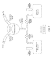
- FIG. 8 is one embodiment of the fluid flow-path schematic of the cassette
- FIG. 9 is an alternate embodiment fluid flow-path schematic for an alternate embodiment of the cassette.
- FIG. 10 is an isometric front view of the exemplary embodiment of the actuation side of the midplate of the cassette with the valves indicated corresponding to FIG. 8 ;
- FIG. 11A-1 is an isometric view of the exemplary embodiment of the outer top plate of the cassette and FIG. 11A-2 is a front view of the exemplary embodiment of the outer top plate of the cassette;
- FIG. 11B-1 is an isometric view of the exemplary embodiment of the inner top plate of the cassette and FIG. 11B-2 is a front view of the exemplary embodiment of the inner top plate of the cassette;
- FIG. 11C is a side view of the exemplary embodiment of the top plate of the cassette.
- FIG. 12A-1 is an isometric view of the exemplary embodiment of the fluid side of the midplate of the cassette and FIG. 12A-2 is a front view of the exemplary embodiment of the fluid side of the midplate of the cassette;
- FIG. 12B-1 is an isometric view of the exemplary embodiment of the air side of the midplate of the cassette and FIG. 12B-2 is a front view of the exemplary embodiment of the air side of the midplate of the cassette;
- FIG. 12C is a side view of the exemplary embodiment of the midplate of the cassette.
- FIG. 13A-1 is an isometric view of the exemplary embodiment of the inner side of the bottom plate of the cassette and FIG. 13A-2 is a front view of the exemplary embodiment of the inner side of the bottom plate of the cassette;
- FIG. 13B-1 is an isometric view of the exemplary embodiment of the outer side of the bottom plate of the cassette and FIG. 13B-2 is a front view of the exemplary embodiment of the outer side of the bottom plate of the cassette;
- FIG. 13C is a side view of the exemplary embodiment of the midplate of the cassette.
- FIG. 14A is a top view of the assembled exemplary embodiment of the cassette
- FIG. 14B is a bottom view of the assembled exemplary embodiment of the cassette
- FIG. 14C is an exploded view of the assembled exemplary embodiment of the cassette
- FIG. 14D is an exploded view of the assembled exemplary embodiment of the cassette
- FIGS. 15A-15C show cross sectional views of the exemplary embodiment of the assembled cassette
- FIG. 16A-1 shows an isometric view of an alternate embodiment of the top plate according to an alternate embodiment of the cassette and FIG. 16A-2 shows a top view of an alternate embodiment of the top plate according to an alternate embodiment of the cassette;
- FIG. 16B-1 shows an isometric view of an alternate embodiment of the top plate according to an alternate embodiment of the cassette and FIG. 16B-2 shows a bottom view of an alternate embodiment of the top plate according to an alternate embodiment of the cassette;
- FIG. 16C shows a side view of the alternate embodiment of the top plate
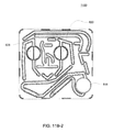
- FIG. 17A-1 shows an isometric view of an alternate embodiment of the midplate according to an alternate embodiment of the cassette and FIG. 17A-2 shows a top view of an alternate embodiment of the midplate according to an alternate embodiment of the cassette;
- FIG. 17B-1 shows an isometric view of an alternate embodiment of the midplate according to an alternate embodiment of the cassette and FIG. 17B-2 shows a bottom view of an alternate embodiment of the midplate according to an alternate embodiment of the cassette;
- FIG. 17C shows a side view of the alternate embodiment of the midplate
- FIG. 18A-1 shows an isometric view of an alternate embodiment of the bottom plate according to an alternate embodiment of the cassette and FIG. 18A-2 shows a top view of an alternate embodiment of the bottom plate according to an alternate embodiment of the cassette;
- FIG. 18B-1 shows an isometric view of an alternate embodiment of the bottom according to an alternate embodiment of the cassette and FIG. 18B-2 shows a bottom view of an alternate embodiment of the bottom according to an alternate embodiment of the cassette;
- FIG. 18C shows a side view of the alternate embodiment of the bottom plate
- FIG. 19A is a top view of an assembled alternate embodiment of the cassette
- FIG. 19B is an exploded view of the assembled alternate embodiment of the cassette.
- FIG. 19C is an exploded view of the assembled alternate embodiment of the cassette.
- FIGS. 20A-20B shows a cross sectional view of the exemplary embodiment of the assembled cassette.
- the pumping cassette includes various features, namely, pod pumps, fluid lines and in some embodiment, valves.
- the cassette embodiments shown and described in this description include exemplary and some alternate embodiments. However, any variety of cassettes having a similar functionality is contemplated.
- the cassette embodiments described herein are implementations of the fluid schematics as shown in FIGS. 8 and 9 , in other embodiments, the cassette may have varying fluid paths and/or valve placement and/or pod pump placements and numbers and thus, is still within the scope of the invention.
- the cassette includes a top plate, a midplate and a bottom plate.
- the top plate includes pump chambers and fluid lines
- the midplate includes complementary fluid lines
- metering pumps and valves and the bottom plate includes actuation chambers (and in some embodiments, the top plate and the bottom plate include complementary portions of a balancing chamber).
- the membranes are located between the midplate and the bottom plate, however, with respect to balancing chambers, a portion of a membrane is located between the midplate and the top plate.
- Some embodiments include where the membrane is attached to the cassette, either overmolded, captured, bonded, press fit, welded in or any other process or method for attachment, however, in the exemplary embodiments, the membranes are separate from the top plate, midplate and bottom plate until the plates are assembled.
- the cassettes may be constructed of a variety of materials. Generally, in the various embodiment, the materials used are solid and non flexible. In the preferred embodiment, the plates are constructed of polysulfone, but in other embodiments, the cassettes are constructed of any other solid material and in exemplary embodiment, of any thermoplastic or thermoset.
- the cassettes are formed by placing the membranes in their correct locations, assembling the plates in order and connecting the plates.
- the plates are connected using a laser welding technique.
- the plates may be glued, mechanically fastened, strapped together, ultrasonically welded or any other mode of attaching the plates together.
- the cassette may be used to pump any type of fluid from any source to any location.
- the types of fluid include nutritive, normutritive, inorganic chemicals, organic chemicals, bodily fluids or any other type of fluid.
- fluid in some embodiments include a gas, thus, in some embodiments, the cassette is used to pump a gas.
- the cassette serves to pump and direct the fluid from and to the desired locations.
- outside pumps pump the fluid into the cassette and the cassette pumps the fluid out.
- the pod pumps serve to pull the fluid into the cassette and pump the fluid out of the cassette.
- valves being in different locations or additional valves are alternate embodiments of this cassette.
- the fluid lines and paths shown in the figures described above are mere examples of fluid lines and paths. Other embodiments may have more, less and/or different fluid paths. In still other embodiments, valves are not present in the cassette.
- the number of pod pumps described above may also vary depending on the embodiment.
- the cassette includes one.
- the cassette includes more than two pod pumps.
- the pod pumps can be single pumps or work in tandem to provide a more continuous flow. Either or both may be used in various embodiments of the cassette.
- the various fluid inlets and fluid outlets are fluid ports.
- a fluid inlet can be a fluid outlet.
- the designation of the fluid port as a fluid inlet or a fluid outlet is only for description purposes.
- the various embodiments have interchangeable fluid ports.
- the fluid ports are provided to impart particular fluid paths onto the cassette. These fluid ports are not necessarily all used all of the time; instead, the variety of fluid ports provides flexibility of use of the cassette in practice.
- FIG. 1A is a sectional view of an exemplary pod pump 100 that is incorporated into a fluid control or pump cassette (see also FIGS. 3 and 4 ), in accordance with an exemplary embodiment of the cassette.
- the pod pump is formed from three rigid pieces, namely a “top” plate 106 , a midplate 108 , and a “bottom” plate 110 (it should be noted that the terms “top” and “bottom” are relative and are used here for convenience with reference to the orientation shown in FIG. 1A ).
- the top and bottom plates 106 and 110 include generally hemispheroid portions that when assembled together define a hemispheroid chamber, which is a pod pump 100 .
- a membrane 112 separates the central cavity of the pod pump into two chambers.
- these chambers are: the pumping chamber that receives the fluid to be pumped and an actuation chamber for receiving the control gas that pneumatically actuates the pump.
- An inlet 102 allows fluid to enter the pumping chamber, and an outlet 104 allows fluid to exit the pumping chamber.
- the inlet 102 and the outlet 104 may be formed between midplate 108 and the top plate 106 .
- Pneumatic pressure is provided through a pneumatic port 114 to either force, with positive gas pressure, the membrane 112 against one wall of the pod pump cavity to minimize the pumping chamber's volume, or to draw, with negative gas pressure, the membrane 112 towards the other wall of the pod pump 100 cavity to maximize the pumping chamber's volume.
- the membrane 112 is provided with a thickened rim 116 , which is held tightly by a protrusion 118 in the midplate 108 .
- the membrane 112 can be placed in and held by the groove 108 before the bottom plate 110 is connected (in the exemplary embodiment) to the midplate 108 .
- a groove is present on the chamber wall.
- the groove acts to prevent folds in the membrane from trapping fluid in the chamber when emptying.
- FIG. 1A a cross sectional view of a reciprocating positive-displacement pump 100 in a cassette is shown.
- the pod pump 100 includes a flexible membrane 112 (also referred to as the “pump diaphragm” or “membrane”) mounted where the pumping chamber (also referred to as a “liquid chamber” or “liquid pumping chamber”) wall 122 and the actuation chamber (also referred to as the “pneumatic chamber”) wall 120 meet.
- the pumping chamber also referred to as a “liquid chamber” or “liquid pumping chamber”
- actuation chamber also referred to as the “pneumatic chamber”
- the membrane 112 effectively divides that interior cavity into a variable-volume pumping chamber (defined by the rigid interior surface of the pumping chamber wall 122 and a surface of the membrane 112 ) and a complementary variable-volume actuation chamber (defined by the rigid interior surface of the actuation chamber wall 120 and a surface of the membrane 112 ).
- the top portion 106 includes a fluid inlet 102 and a fluid outlet 104 , both of which are in fluid communication with the pumping/liquid chamber.
- the bottom portion 110 includes an actuation or pneumatic interface 114 in fluid communication with the actuation chamber.
- the membrane 112 can be urged to move back and forth within the cavity by alternately applying negative or vent to atmosphere and positive pneumatic pressure at the pneumatic interface 114 . As the membrane 112 reciprocates back and forth, the sum of the volumes of the pumping and actuation chambers remains constant.
- the application of negative or vent to atmosphere pneumatic pressure to the actuation or pneumatic interface 114 tends to withdraw the membrane 112 toward the actuation chamber wall 120 so as to expand the pumping/liquid chamber and draw fluid into the pumping chamber through the inlet 102
- the application of positive pneumatic pressure tends to push the membrane 112 toward the pumping chamber wall 122 so as to collapse the pumping chamber and expel fluid in the pumping chamber through the outlet 104
- the interior surfaces of the pumping chamber wall 122 and the actuation chamber wall 120 limit movement of the membrane 112 as it reciprocates back and forth. In the embodiment shown in FIG.
- the interior surfaces of the pumping chamber wall 122 and the actuation chamber wall 120 are rigid, smooth, and hemispherical.
- an alternative rigid limit structure for example, a portion of a bezel used for providing pneumatic pressure and/or a set of ribs—may be used to limit the movement of the membrane as the pumping chamber approaches maximum value.
- Bezels and rib structures are described generally in U.S. patent application Ser. No. 10/697,450 entitled BEZEL ASSEMBLY FOR PNEUMATIC CONTROL filed on Oct. 30, 2003 and published as Publication No. US 2005/0095154 and related PCT Application No.
- the rigid limit structure such as the rigid actuation chamber wall 120 , a bezel, or a set of ribs—defines the shape of the membrane 112 when the pumping chamber is at its maximum value.
- the membrane 112 (when urged against the rigid limit structure) and the rigid interior surface of the pumping chamber wall 122 define a spherical pumping chamber volume when the pumping chamber volume is at a minimum.
- movement of the membrane 112 is limited by the pumping chamber wall 122 and the actuation chamber wall 120 .
- the membrane 112 will move from a position limited by the actuation chamber wall 120 to a position limited by the pumping chamber wall 122 .
- the membrane and the pumping chamber wall 122 define the maximum volume of the pumping chamber.
- the pumping chamber is at its minimum volume.
- the pumping chamber wall 122 and the actuation chamber wall 120 both have a hemispheroid shape so that the pumping chamber will have a spheroid shape when it is at its maximum volume.
- a pumping chamber that attains a spheroid shape—and particularly a spherical shape—at maximum volume circulating flow may be attained throughout the pumping chamber.
- Such shapes accordingly tend to avoid stagnant pockets of fluid in the pumping chamber.
- the orientations of the inlet 102 and outlet 104 also tend to have an impact on the flow of fluid through the pumping chamber and in some embodiments, reduce the likelihood of stagnant pockets of fluid forming.
- the spherical shape (and spheroid shapes in general) tends to create less shear and turbulence as the fluid circulates into, through, and out of the pumping chamber.
- a raised flow path 30 is shown in the pumping chamber.
- This raised flow path 30 allows for the fluid to continue flowing through the pod pumps after the membrane reaches the end of stroke.
- the raised flow path 30 minimizes the chances of the membrane causing air or fluid to be trapped in the pod pump or the membrane blocking the inlet or outlet of the pod pump which would inhibit continuous flow.
- the raised flow path 30 is shown in the exemplary embodiment having particular dimensions, however, in alternate embodiments, as seen in FIGS.
- the raised flow path 30 is narrower, or in still other embodiments, the raised flow path 30 can be any dimensions as the purpose is to control fluid flow so as to achieve a desired flow rate or behavior of the fluid.
- the dimensions shown and described here with respect to the raised flow path, the pod pumps, the valves or any other aspect are mere exemplary and alternate embodiments. Other embodiments are readily apparent.
- a balancing pod is constructed similar to the pod pump described above with respect to FIG. 1A .
- a balancing pod includes two fluid balancing chambers, rather than an actuation chamber and a pumping chamber, and does not include an actuation port.
- each balancing chamber includes an inlet 102 and an outlet 104 .
- a groove 126 is included on each of the balancing chamber walls 120 , 122 . The groove 126 is described in further detail below.
- the membrane 112 provides a seal between the two chambers.
- the balancing chambers work to balance the flow of fluid into and out of the chambers such that both chambers maintain an equal volume rate flow.
- the inlets 102 and outlets 104 for each chamber are shown to be on the same side, in other embodiments, the inlets 102 and outlets 104 for each chamber are on different sides. Also, the inlets 102 and outlets 104 can be on either side, depending on the flow path in which the balancing chamber is integrated.
- the membrane 112 includes an embodiment similar to the one described below with respect to FIG. 6A-6G .
- the membrane 112 can be over molded or otherwise constructed such that a double-ring seal is not applicable.
- the metering pump can be any pump that is capable of adding any fluid or removing any fluid.
- the fluids include but are not limited to pharmaceuticals, inorganic compounds or elements, organic compounds or elements, nutraceuticals, nutritional elements or compounds or solutions, or any other fluid capable of being pumped.
- the metering pump is a membrane pump.
- the metering pump is a smaller volume pod pump.
- the metering pump includes an inlet and an outlet, similar to a larger pod pump (as shown in FIG. 1A for example). However, the inlet and outlet are generally much smaller than a pod pump and, in one exemplary embodiment, includes a volcano valve-like raised ring around either the inlet or outlet.
- Metering pumps include a membrane, and various embodiments of a metering pump membrane are shown in FIGS. 5E-5H .
- the metering pump in some embodiments, pumps a volume of fluid out of the fluid line. Once the fluid is in the pod pump, a reference chamber, located outside the cassette, using the FMS, determines the volume that has been removed.
- this volume of fluid that has been removed will not then flow to the fluid outlet, the balance chambers or to a pod pump.
- the metering pump is used to remove a volume of fluid from a fluid line. In other embodiments, the metering pump is used to remove a volume of fluid to produce other results.
- FMS may be used to perform certain fluid management system measurements, such as, for example, measuring the volume of subject fluid pumped through the pump chamber during a stroke of the membrane or detecting air in the pumping chamber, e.g., using techniques described in U.S. Pat. Nos. 4,808,161; 4,826,482; 4,976,162; 5,088,515; and 5,350,357, which are hereby incorporated herein by reference in their entireties.
- Metering pumps are also used in various embodiments to pump a second fluid into the fluid line.
- the metering pump is used to pump a therapeutic or a compound into a fluid line.
- One embodiment uses the metering pump to pump a volume of compound into a mixing chamber in order to constitute a solution.
- the metering pumps are configured for FMS volume measurement. In other embodiments, the metering pumps are not.
- a small fixed reference air chamber is located outside of the cassette, for example, in the pneumatic manifold (not shown).
- a valve isolates the reference chamber and a second pressure sensor.
- the stroke volume of the metering pump may be precisely computed by charging the reference chamber with air, measuring the pressure, and then opening the valve to the pumping chamber.
- the volume of air on the chamber side may be computed based on the fixed volume of the reference chamber and the change in pressure when the reference chamber was connected to the pump chamber.
- the exemplary embodiment of the cassette includes one or more valves. Valves are used to regulate flow by opening and closing fluid lines.
- the valves included in the various embodiments of the cassette include one or more of the following: volcano valves or smooth valves. In some embodiment of the cassette, check valves may be included. Embodiments of the volcano valve are shown in FIGS. 2A and 2B , while an embodiment of the smooth valve is shown in FIG. 2C . Additionally, FIGS. 3 and 4 show cross sections of one embodiment of a pod pump in a cassette with an inlet and an outlet valve.
- reciprocating positive-displacement pumps of the types just described may include, or may be used in conjunction with, various valves to control fluid flow through the pump.
- the reciprocating positive-displacement pump or the balancing pods may include, or be used in conjunction with, an inlet valve and/or an outlet valve.
- the valves may be passive or active.
- the membrane is urged back and forth by positive and negative pressurizations, or by positive and vent to atmosphere pressurizations, of a gas provided through the pneumatic port, which connects the actuation chamber to a pressure actuation system.
- active valves control the fluid flow through the pump(s) and the cassette.
- the active valves may be actuated by a controller in such a manner as to direct flow in a desired direction.
- a controller in such a manner as to direct flow in a desired direction.
- Such an arrangement would generally permit the controller to cause flow in either direction through the pod pump.
- the flow would normally be in a first direction, e.g., from the inlet to the outlet. At certain other times, the flow may be directed in the opposite direction, e.g., from the outlet to the inlet.
- Such reversal of flow may be employed, for example, during priming of the pump, to check for an aberrant line condition (e.g., a line occlusion, blockage, disconnect, or leak), or to clear an aberrant line condition (e.g., to try to dislodge a blockage).
- an aberrant line condition e.g., a line occlusion, blockage, disconnect, or leak
- an aberrant line condition e.g., to try to dislodge a blockage
- Pneumatic actuation of valves provides pressure control and a natural limit to the maximum pressure that may be developed in a system.
- pneumatic actuation has the added benefit of providing the opportunity to locate all the solenoid control valves on one side of the system away from the fluid paths.
- the volcano valves are pneumatically controlled valves that may be used in embodiments of the cassette.
- a membrane 202 along with the midplate 204 , defines a valving chamber 206 .
- Pneumatic pressure is provided through a pneumatic port 208 to either force, with positive gas pressure, the membrane 202 against a valve seat 210 to close the valve, or to draw, with negative gas pressure, or in some embodiments, with vent to atmospheric pressure, the membrane away from the valve seat 210 to open the valve.
- a control gas chamber 212 is defined by the membrane 202 , the top plate 214 , and the midplate 204 .
- the midplate 204 has an indentation formed on it, into which the membrane 202 is placed so as to form the control gas chamber 212 on one side of the membrane 202 and the valving chamber 206 on the other side.
- the pneumatic port 208 is defined by a channel formed in the top plate 214 .
- valves can be ganged together so that all the valves ganged together can be opened or closed at the same time by a single source of pneumatic pressure.
- Channels formed on the midplate 204 corresponding with fluid paths along with the bottom plate 216 , define the valve inlet 218 and the valve outlet 220 . Holes formed through the midplate 204 provide communication between the inlet 218 and the valving chamber 206 and between the valving chamber 206 and the outlet 220 .
- the membrane 202 is provided with a thickened rim 222 , which fits tightly in a groove 224 in the midplate 204 .
- the membrane 202 can be placed in and held by the groove 224 before the top plate 214 is connected to the midplate 204 .
- this valve design may impart benefits in manufacturing.
- the top plate 214 may include additional material extending into control gas chamber 212 so as to prevent the membrane 202 from being urged too much in a direction away from the groove 224 , so as to prevent the membrane's thickened rim 222 from popping out of the groove 224 .
- the location of the pneumatic port 208 with respect to the control gas chamber 212 varies in the two embodiments shown in FIGS. 2A and 2B .
- FIG. 2C shows an embodiment in which the valving chamber lacks a valve seat feature. Rather, in FIG. 2C , the valve in this embodiment does not include any volcano features and thus, the valving chamber 206 , i.e., the fluid side, does not include any raised features and thus is smooth. This embodiment is used in cassettes used to pump fluid sensitive to shearing.
- FIG. 2D shows an embodiment in which the valving chamber has a raised area to aid in the sealing of the valving membrane.
- FIGS. 2E-2G various embodiments of the valve membrane are shown. Although some exemplary embodiments have been shown and described, in other embodiments, variations of the valve and valving membrane may be used.
- the membrane has a variable cross-sectional thickness, as shown in FIG. 4 .
- Thinner, thicker or variable thickness membranes may be used to accommodate the strength, flexural and other properties of the chosen membranes materials.
- Thinner, thicker or variable membrane wall thickness may also be used to manage the membrane thereby encouraging it to flex more easily in some areas than in other areas, thereby aiding in the management of pumping action and flow of subject fluid in the pump chamber.
- the membrane is shown having its thickest cross-sectional area closest to its center.
- the thickest and thinnest areas may be in any location on the membrane.
- the thinner cross-section may be located near the center and the thicker cross-sections located closer to the perimeter of the membrane. Still other configurations are possible.
- FIGS. 5A-5D one embodiment of a membrane is shown having various surface embodiments, these include smooth ( FIG. 5A ), rings ( FIG. 5D ), ribs ( FIG. 5C ), dimples or dots ( FIG. 5B ) of variable thickness and or geometry located at various locations on the actuation and or pumping side of the membrane.
- the membrane has a tangential slope in at least one section, but in other embodiments, the membrane is completely smooth or substantially smooth.
- the membrane has a dimpled or dotted surface.
- the membrane may be made of any flexible material having a desired durability and compatibility with the subject fluid.
- the membrane can be made from any material that may flex in response to fluid, liquid or gas pressure or vacuum applied to the actuation chamber.
- the membrane material may also be chosen for particular bio-compatibility, temperature compatibility or compatibility with various subject fluids that may be pumped by the membrane or introduced to the chambers to facilitate movement of the membrane.
- the membrane is made from high elongation silicone.
- the membrane is made from any elastomer or rubber, including, but not limited to, silicone, urethane, nitrile, EPDM or any other rubber, elastomer or flexible material.
- the shape of the membrane is dependent on multiple variables. These variables include, but are not limited to: the shape of the chamber; the size of the chamber; the subject fluid characteristics; the volume of subject fluid pumped per stroke; and the means or mode of attachment of the membrane to the housing.
- the size of the membrane is dependent on multiple variables. These variables include, but are not limited to: the shape of the chamber; the size of the chamber; the subject fluid characteristics; the volume of subject fluid pumped per stroke; and the means or mode of attachment of the membrane to the housing. Thus, depending on these or other variables, the shape and size of the membrane may vary in various embodiments.
- the membrane can have any thickness. However, in some embodiments, the range of thickness is between 0.002 inches to 0.125 inches. Depending on the material used for the membrane, the desired thickness may vary. In one embodiment, high elongation silicone is used in a thickness ranging from 0.015 inches to 0.050 inches. However in other embodiments, the thickness may vary.
- the membrane is pre-formed to include a substantially dome-shape in at least part of the area of the membrane.
- a substantially dome-shape in at least part of the area of the membrane.
- FIGS. 4E and 4F One embodiment of the dome-shaped membrane is shown in FIGS. 4E and 4F . Again, the dimensions of the dome may vary based on some or more of the variables described above. However, in other embodiments, the membrane may not include a pre-formed dome shape.
- the membrane dome is formed using liquid injection molding.
- the dome may be formed by using compression molding.
- the membrane is substantially flat.
- the dome size, width or height may vary.
- the membrane may be held in place by various means and methods.
- the membrane is clamped between the portions of the cassette, and in some of these embodiments, the rim of the cassette may include features to grab the membrane.
- the membrane is clamped to the cassette using at least one bolt or another device.
- the membrane is over-molded with a piece of plastic and then the plastic is welded or otherwise attached to the cassette.
- the membrane is pinched between the mid plate described with respect to FIGS. 1A and 1B and the bottom plate.
- any method or means for attaching the membrane to the cassette can be used.
- the membrane in one alternate embodiment, is attached directly to one portion of the cassette.
- the membrane is thicker at the edge, where the membrane is pinched by the plates, than in other areas of the membrane. In some embodiments, this thicker area is a gasket, in some embodiments an O-ring, ring or any other shaped gasket.
- a gasket in some embodiments an O-ring, ring or any other shaped gasket.
- the membrane is shown with two gaskets 62 , 64 . In some of these embodiments, the gasket(s) 62 , 64 provides the attachment point of the membrane to the cassette. In other embodiments, the membrane includes more than two gaskets. Membranes with one gasket are also included in some embodiments (see FIGS. 4A-4D ).
- the gasket is contiguous with the membrane. However, in other embodiments, the gasket is a separate part of the membrane. In some embodiments, the gasket is made from the same material as the membrane. However, in other embodiments, the gasket is made of a material different from the membrane. In some embodiments, the gasket is formed by over-molding a ring around the membrane. The gasket can be any shape ring or seal desired so as to complement the pod pump housing embodiment. In some embodiments, the gasket is a compression type gasket.
- a mixing pod includes a chamber for mixing.
- the mixing pod is a flexible structure, and in some embodiments, at least a section of the mixing pod is a flexible structure.
- the mixing pod can include a seal, such as an o-ring, or a membrane.
- the mixing pod can be any shape desired.
- the mixing pod is similar to a pod pump except it does not include a membrane and does not include an actuation port.
- Some embodiments of this embodiment of the mixing pod include an o-ring seal to seal the mixing pod chamber.
- the mixing pod is a spherical hollow pod with a fluid inlet and a fluid outlet.
- the chamber size can be any size desired.
- FIG. 7 is a schematic showing an embodiment of a pressure actuation system that may be used to actuate a pod pump with both positive and negative pressure, such as the pod pump shown in FIG. 1A .
- the pressure actuation system is capable of intermittently or alternately providing positive and negative pressurizations to the gas in the actuation chamber of the pod pump.
- FIG. 7 does not apply in these embodiments, actuation of the pod pump is accomplished by applying positive pressure and vent to atmosphere (again, not shown in FIG. 7 ).
- the pod pump including the flexible membrane, the inlet, the outlet, the pneumatic port, the pumping chamber, the actuation chamber, and possibly including an inlet check valve and an outlet check valve or other valves—is part of a larger disposable system.
- the pneumatic actuation system including an actuation-chamber pressure transducer, a positive-supply valve, a negative-supply valve, a positive-pressure gas reservoir, a negative-pressure gas reservoir, a positive-pressure-reservoir pressure transducer, a negative-pressure-reservoir pressure transducer, as well as an electronic controller including, in some embodiments, a user interface console (such as a touch-panel screen)—may be part of a base unit.
- the positive-pressure reservoir provides to the actuation chamber the positive pressurization of a control gas to urge the membrane towards a position where the pumping chamber is at its minimum volume (i.e., the position where the membrane is against the rigid pumping-chamber wall).
- the negative-pressure reservoir provides to the actuation chamber the negative pressurization of the control gas to urge the membrane in the opposite direction, towards a position where the pumping chamber is at its maximum volume (i.e., the position where the membrane is against the rigid actuation-chamber wall).
- a valving mechanism is used to control fluid communication between each of these reservoirs and the actuation chamber.
- a separate valve is used for each of the reservoirs; a positive-supply valve controls fluid communication between the positive-pressure reservoir and the actuation chamber, and a negative-supply valve controls fluid communication between the negative-pressure reservoir and the actuation chamber.
- These two valves are controlled by the controller.
- a single three-way valve may be used in lieu of the two separate valves.
- the valves may be binary on-off valves or variable-restriction valves.
- the controller also receives pressure information from the three pressure transducers: an actuation-chamber pressure transducer, a positive-pressure-reservoir pressure transducer, and a negative-pressure-reservoir pressure transducer. As their names suggest, these transducers respectively measure the pressure in the actuation chamber, the positive-pressure reservoir, and the negative-pressure reservoir.
- the actuation-chamber-pressure transducer is located in a base unit but is in fluid communication with the actuation chamber through the pod pump pneumatic port.
- the controller monitors the pressure in the two reservoirs to ensure they are properly pressurized (either positively or negatively).
- the positive-pressure reservoir may be maintained at around 750 mmHG, while the negative-pressure reservoir may be maintained at around ⁇ 450 mmHG.
- a compressor-type pump or pumps may be used to maintain the desired pressures in these reservoirs.
- two independent compressors may be used to respectively service the reservoirs.
- Pressure in the reservoirs may be managed using a simple bang-bang control technique in which the compressor servicing the positive-pressure reservoir is turned on if the pressure in the reservoir falls below a predetermined threshold and the compressor servicing the negative-pressure reservoir is turned on if the pressure in the reservoir is above a predetermined threshold.
- the amount of hysteresis may be the same for both reservoirs or may be different. Tighter control of the pressure in the reservoirs can be achieved by reducing the size of the hysteresis band, although this will generally result in higher cycling frequencies of the compressors. If very tight control of the reservoir pressures is required or otherwise desirable for a particular application, the bang-bang technique could be replaced with a PID control technique and could use PWM signals on the compressors.
- the pressure provided by the positive-pressure reservoir is preferably strong enough—under normal conditions—to urge the membrane all the way against the rigid pumping-chamber wall.
- the negative pressure (i.e., the vacuum) provided by the negative-pressure reservoir is preferably strong enough—under normal conditions—to urge the membrane all the way against the actuation-chamber wall.
- these positive and negative pressures provided by the reservoirs are within safe enough limits that even with either the positive-supply valve or the negative-supply valve open all the way, the positive or negative pressure applied against the membrane is not so strong as to damage the pod pump or create unsafe fluid pressures (e.g., that may harm a patient receiving pumped blood or other fluid).
- pneumatic actuation systems may be used to move the membrane back and forth instead of the two-reservoir pneumatic actuation system shown in FIG. 7 , although a two-reservoir pneumatic actuation system is generally preferred.
- alternative pneumatic actuation systems may include either a single positive-pressure reservoir or a single negative-pressure reservoir along with a single supply valve and a single tank pressure sensor, particularly in combination with a resilient membrane.
- Such pneumatic actuation systems may intermittently provide either a positive gas pressure or a negative gas pressure to the actuation chamber of the pod pump.
- the pump may be operated by intermittently providing positive gas pressure to the actuation chamber, causing the membrane to move toward the pumping chamber wall and expel the contents of the pumping chamber, and releasing the gas pressure, causing the membrane to return to its relaxed position and draw fluid into the pumping chamber.
- the pump may be operated by intermittently providing negative gas pressure to the actuation chamber, causing the membrane to move toward the actuation chamber wall and draw fluid into the pumping chamber, and releasing the gas pressure, causing the membrane to return to its relaxed position and expel fluid from the pumping chamber.
- a fluid valve in the exemplary embodiment consists of a small chamber with a flexible membrane or membrane across the center dividing the chamber into a fluid half and a pneumatic half.
- the fluid valve in the exemplary embodiment, has 3 entry/exit ports, two on the fluid half of the chamber and one the pneumatic half of the chamber.
- the port on the pneumatic half of the chamber can supply either positive pressure or vacuum (or rather than vacuum, in some embodiments, there is a vent to atmosphere) to the chamber.
- a vacuum is applied to the pneumatic portion of the chamber, the membrane is pulled towards the pneumatic side of the chamber, clearing the fluid path and allowing fluid to flow into and out of the fluid side of the chamber.
- the membrane When positive pressure is applied to the pneumatic portion of the chamber, the membrane is pushed towards the fluid side of the chamber, blocking the fluid path and preventing fluid flow.
- the membrane In the volcano valve embodiment (as shown in FIGS. 2A-2B ) on one of the fluid ports, that port seals off first when closing the valve and the remainder of any fluid in the valve is expelled through the port without the volcano feature.
- the raised feature between the two ports allows for the membrane to seal the two ports from each other earlier in the actuation stroke (i.e., before the membrane seals the ports directly).
- pressure valves are used to operate the pumps located at different points in the flow path.
- This architecture supports pressure control by using two variable-orifice valves and a pressure sensor at each pump chamber which requires pressure control.
- one valve is connected to a high-pressure source and the other valve is connected to a low-pressure sink.
- a high-speed control loop monitors the pressure sensor and controls the valve positions to maintain the necessary pressure in the pump chamber.
- Pressure sensors are used to monitor pressure in the pneumatic portion of the chambers themselves. By alternating between positive pressure and vacuum on the pneumatic side of the chamber, the membrane is cycled back and forth across the total chamber volume. With each cycle, fluid is drawn through the upstream valve of the inlet fluid port when the pneumatics pull a vacuum on the pods. The fluid is then subsequently expelled through the outlet port and the downstream valve when the pneumatics deliver positive pressure to the pods.
- pressure pumps consist of a pair of chambers. When the two chambers are run 180 degrees out of phase from one another the flow is essentially continuous.
- pressure pod pumps which can detect end-of-stroke.
- An outer control loop determines the correct pressure values to deliver the required flow.
- Pressure pumps can run an end of stroke algorithm to detect when each stroke completes. While the membrane is moving, the measured pressure in the chamber tracks a desired sinusoidal pressure. When the membrane contacts a chamber wall, the pressure becomes constant, no longer tracking the sinusoid. This change in the pressure signal is used to detect when the stroke has ended, i.e., the end-of-stroke.
- the pressure pumps have a known volume.
- an end of stroke indicates a known volume of fluid is in the chamber.
- fluid flow may be controlled using rate equating to volume.
- FMS may be used to determine the volume of fluid pumped by the metering pumps.
- the metering pump may pump fluid without using the FMS volume measurement system, however, in the exemplary embodiments, the FMS volume measurement system is used to calculate the exact volume of fluid pumped.
- first valving path an inlet can be an outlet, as well, an indication of a first, second, third fluid does not denote that they are different fluids or are in a particular hierarchy.
- the denotations simply refer to separate entrance areas into the cassette and the first, second, third, etc, fluids may be different fluids or the same fluid types or composition or two or more may be the same.
- the designation of the first, second, third, etc. valving paths do not have any particular meaning, but are used for clearness of description.
- first fluid outlet second fluid outlet
- a fluid may travel out of or into the cassette via that inlet/outlet.
- more than one inlet/outlet on the schematic is designated with an identical name. This merely describes that all of the inlet/outlets having that designation are pumped by the same metering pump or set of pod pumps (which in alternate embodiments, can be a single pod pump).
- the cassette 800 includes at least one pod pump 828 , 820 and at least one mixing chamber 818 .
- the cassette 800 also includes a first fluid inlet 810 , where a first fluid enters the cassette.
- the first fluid includes a flow rate provided by one of the at least one pod pump 820 , 828 in the cassette 800 .
- the cassette 800 also includes a first fluid outlet 824 where fluid exits the cassette 800 having a flow rate provided by one of the at least one pod pump 820 , 828 .
- the cassette 800 includes at least one metering fluid line 812 , 814 , 816 that is in fluid connection with the first fluid outlet.
- the cassette also includes at least one second fluid inlet 826 where the second fluid enters the cassette 800 .
- a third fluid inlet 825 is also included.
- Metering pumps 822 , 830 pump the second fluid and the third fluid into the first fluid outlet line.
- the second fluid and, in some embodiments, the third fluid, connected to the cassette 800 at the second fluid inlet 826 and third fluid inlet 825 respectively, are each fluidly connected to a metering pump 822 , 830 and to the first fluid outlet line through a metering fluid line 812 , 814 , 816 .
- the metering pumps 822 , 830 described in more detail below, in the exemplary embodiment, include a volume measurement capacity such that the volume of fluid pumped by the metering pumps 822 , 830 is readily discernable.
- the mixing chamber 818 is connected to the first fluid outlet line 824 and includes a fluid inlet and a fluid outlet.
- sensors are located upstream and downstream from the mixing chamber 818 . The location of the sensors in the exemplary embodiment are shown and described below with respect to FIGS. 14C, 14D and FIGS. 15B and 15C .
- the cassette 800 is capable of internally mixing a solution made up of at least two components.
- the cassette 800 also includes the capability of constituting a powder to a fluid prior to pumping the fluid into the mixing chamber. These capabilities will be described in greater detail below.
- valves 832 - 860 impart the various capabilities of the cassette 800 .
- the components of the cassette 800 may be used differently in the different embodiments based on various valving controls.
- the fluid schematic of the cassette 800 shown in FIG. 8 may be embodied into various cassette apparatus.
- the embodiments of the cassette 800 including the fluid schematic shown in FIG. 8 are not the only cassette embodiments that may incorporate this or an alternate embodiment of this fluid schematic.
- the types of valves, the ganging of the valves, the number of pumps and chambers may vary in various cassette embodiments of this fluid schematic.
- a fluid flow-path schematic 800 is shown with the fluid paths indicated based on different valving flow paths.
- the fluid flow-path schematic 800 is described herein corresponding to the valving flow paths in one embodiment of the cassette.
- the exemplary embodiment of the midplate 900 of the cassette are shown in FIG. 10 with the valves indicated corresponding to the respective fluid flow-path schematic 800 in FIG. 8 .
- the fluid flow paths will be described based on the valving.
- the term “valving path” refers to a fluid path that may, in some embodiments, be available based on the control of particular valves.
- the corresponding fluid side structures of FIG. 10 are shown in FIGS. 12A-1 and 12A-2 .
- the first valving path includes valves 858 , 860 .
- This valving path 858 , 860 includes the metering fluid line 812 , which connects to the second fluid inlet 826 .
- these two second fluid inlets 826 can be connected to the same fluid source or a different fluid source. Either way, the same fluid or a different fluid may be connected to each second fluid inlet 826 .
- Each second fluid inlet 826 is connected to a different metering fluid line 812 , 814 .
- the first of the two metering fluid lines connected to the second fluid inlet 826 is as follows.
- valve 858 opens and valve 860 is closed and metering pump 822 is actuated, fluid is drawn from the second fluid inlet 826 and into metering fluid line 812 .
- valve 860 is open and valve 858 is closed and the metering pump 822 is actuated, second fluid continues on metering fluid line 812 into pod pump 820 .
- valve 842 when valve 842 is open and pod pump 820 is actuated, fluid is pumped from pod pump 820 to one of the third fluid inlet 825 .
- this valving path is provided to send liquid into a container or source connected to third fluid inlet 825 .
- this valving path 832 , 835 includes the metering fluid line 816 , which connects to the third fluid inlet 825 .
- the metering fluid line 816 connects to the third fluid inlet 825 .
- these two third fluid inlets 825 can be connected to the same fluid source or a different fluid source. Either way, the same fluid or a different fluid may be connected to each third fluid inlet 825 .
- Each third fluid inlet 825 is connected to a different metering fluid line 862 , 868 .
- valve 832 opens and valve 836 is closed and metering pump 830 is actuated, fluid is drawn from the third fluid inlet 825 and into metering fluid line 830 .
- valve 836 is open and valve 832 is closed and the metering pump 830 is actuated, third fluid continues on metering fluid line 816 into first fluid outlet line 824 .
- valve 846 when valve 846 is open and pod pump 820 is actuated, fluid is pumped from pod pump 820 to one of the third fluid inlet 825 .
- this valving path is provided to send liquid into a container or source connected to third fluid inlet 825 .
- valve 850 opens and pod pump 820 is actuated, fluid is pumped into the cassette 800 through the first fluid inlet 810 , and into pod pump 820 .
- valve 838 when valve 838 is open and pod pump 820 is actuated, fluid is pumped from pod pump 820 to the mixing chamber 818 and to the first fluid outlet 824 .
- the seventh valving path includes valves 858 , 856 .
- This valving path 858 , 856 includes the metering fluid line 812 , which connects to the second fluid inlet 826 .
- these two second fluid inlets 826 can be connected the same fluid source or a different fluid source. Either way, the same fluid or a different fluid may be connected to each second fluid inlet 826 .
- Each second fluid inlet 826 is connected to a different metering fluid line 812 , 814 .
- valve 858 opens and valve 856 is closed and metering pump 822 is actuated, fluid is drawn from the second fluid inlet 826 and into metering fluid line 812 .
- valve 856 is open and valve 858 is closed, and the metering pump is actuated, second fluid continues on metering fluid line 814 into pod pump 828 .
- valve 848 when valve 848 is open and pod pump 828 is actuated, fluid is pumped from pod pump 828 to one of the third fluid inlet 825 .
- this valving path is provided to send fluid/liquid into a container or source connected to third fluid inlet 825 .
- valve 844 when valve 844 is open and pod pump 828 is actuated, fluid is pumped from pod pump 828 to one of the third fluid inlet 825 .
- this valving path is provided to send liquid into a container or source connected to third fluid inlet 825 .
- valve 848 when valve 848 is open and pod pump 828 is actuated, fluid is pumped from pod pump 828 to one of the third fluid inlet 825 .
- this valving path is provided to send fluid/liquid into a container or source connected to third fluid inlet 825 .
- the eleventh valving path including valves 854 and 856 is shown.
- This valving path 854 , 856 includes the metering fluid line 814 , which connects to the second fluid inlet 826 .
- these two second fluid inlets 826 can be connected the same fluid source or a different fluid source. Either way, the same fluid or a different fluid may be connected to each second fluid inlet 826 .
- Each second fluid inlet 826 is connected to a different metering fluid line 812 , 814 .
- the second of the two metering fluid lines connected to the second fluid inlet 826 is shown in FIG. 8 .
- the twelfth valving path is as follows. When valve 854 opens and valve 856 is closed and metering pump 822 is actuated, fluid is drawn from the second fluid inlet 826 and into metering fluid line 814 . When valve 856 is open and valve 854 is closed and the metering pump 822 is actuated, the second fluid continues on metering fluid line 814 into pod pump 828 .
- valve 854 opens and valve 860 is closed and metering pump 822 is actuated, fluid is drawn from the second fluid inlet 826 and into metering fluid line 814 .
- valve 860 is open and valve 854 is closed, and the metering pump 822 is actuated, the second fluid continues on metering fluid line 814 into pod pump 820 .
- valve 852 opens and pod pump 828 is actuated, fluid is pumped into the cassette 800 through the first fluid inlet 810 , and into pod pump 828 .
- valve 840 when valve 840 is open and pod pump 828 is actuated, fluid is pumped from pod pump 828 to the mixing chamber 818 and to the first fluid outlet 824 .
- the sixteenth valving path including valve 834 when valve 834 is open and valve 836 opens, and the metering pump 830 is actuated, fluid from the third fluid inlet 825 flows on metering fluid line 862 and to metering fluid line 816 .
- valves are open individually.
- the valves are pneumatically open.
- the fluid valves are volcano valves, as described in more detail in this specification.
- the top plate 1100 of exemplary embodiment of the cassette is shown.
- the pod pumps 820 , 828 and the mixing chambers 818 on the top plate 1100 are formed in a similar fashion.
- the pod pumps 820 , 828 and mixing chamber 818 when assembled with the bottom plate, have a total volume of capacity of 38 ml.
- the mixing chamber can have any size volume desired.
- FIGS. 11B 11 B- 1 and 11 B- 2 the bottom view of the top plate 1100 is shown.
- the fluid paths are shown in this view. These fluid paths correspond to the fluid paths shown in FIGS. 12A-1, 12A-2, 12B-1, and 12B-2 in the midplate 1200 .
- the top plate 1100 and the top of the midplate 1200 form the liquid or fluid side of the cassette for the pod pumps 820 , 828 and for one side of the mixing chamber 818 . Thus, most of the liquid flow paths are on the top 1100 and midplates 1200 .
- FIGS. 12B-1 and 12B-2 the first fluid inlet 810 and the first fluid outlet 824 are shown.
- the pod pumps 820 , 828 include a groove 1002 (in alternate embodiments, this is a groove).
- the groove 1002 is shown having a particular size and shape, however, in other embodiments, the size and shape of the groove 1002 can be any size or shape desirable.
- the size and shape shown in FIGS. 11A-1, 11A-2, 11B-1, and 11B-2 is the exemplary embodiment.
- the groove 1002 forms a path between the fluid inlet side and the fluid outlet side of the pod pumps 820 , 828 .
- the groove 1002 is a groove in the inner pumping chamber wall of the pod pump.
- the groove 1002 provides a fluid path whereby when the membrane is at the end-of-stroke there is still a fluid path between the inlet and outlet such that the pockets of fluid or air do not get trapped in the pod pump.
- the groove 1002 is included in both the liquid/fluid and air/actuation sides of the pod pumps 820 , 828 .
- the groove 1002 may also be included in the mixing chamber 818 (see FIGS. 13A-1, 13A-2, 13B-1, and 13B-2 with respect to the actuation/air side of the pod pumps 820 , 828 and the opposite side of the mixing chamber 818 .
- the groove 1002 is either not included or on only one side of the pod pumps 820 , 828 .
- the liquid/fluid side of the pod pumps 820 , 828 may include a feature (not shown) whereby the inlet and outlet flow paths are continuous and a rigid outer ring (not shown) is molded about the circumference of the pumping chamber is also continuous. This feature allows for the seal, formed with the membrane (not shown) to be maintained.
- FIG. 11E the side view of the exemplary embodiment of the top plate 1100 is shown.
- FIGS. 12A-1, 12A-2, 12B-1, and 12B-2 the exemplary embodiment of the midplate 1200 is shown.
- the midplate 1200 is also shown in FIGS. 9A-9F and 10A-10F , where these FIGS. correspond with FIGS. 12A-1, 12A-2, 12B-1, and 12B-2 .
- FIGS. 9A-9F and 10A-10F indicate the locations of the various valves and valving paths.
- the locations of the membranes (not shown) for the respective pod pumps 820 , 828 as well as the location of the mixing chamber 818 are shown.
- sensor elements are incorporated into the cassette so as to discern various properties of the fluid being pumped.
- three sensor elements are included.
- six sensor elements (two sets of three) are included.
- the sensor elements are located in the sensor cell 1314 , 1316 .
- a sensor cell 1314 , 1316 is included as an area on the cassette for sensor(s) elements.
- the three sensor elements of the two sensor cells 1314 , 1316 are housed in respective sensor elements housings 1308 , 1310 , 1312 and 1318 , 1320 , 1322 .
- two of the sensor elements housings 1308 , 1312 and 1318 , 1320 accommodate a conductivity sensor elements and the third sensor elements housing 1310 , 1322 accommodates a temperature sensor elements.
- the conductivity sensor elements and temperature sensor elements can be any conductivity or temperature sensor elements in the art.
- the conductivity sensors are graphite posts.
- the conductivity sensor elements are posts made from stainless steel, titanium, platinum or any other metal coated to be corrosion resistant and still be electrically conductive.
- the conductivity sensor elements will include an electrical lead that transmits the probe information to a controller or other device.
- the temperature sensor is a thermister potted in a stainless steel probe.
- FIG. 12C the side view of the exemplary embodiment of the midplate 1200 is shown.
- FIGS. 13A-1, 13A-2, 13B-1, and 13B-2 the bottom plate 1300 is shown.
- the inner or inside surface of the bottom plate 1300 is shown.
- the inner or inside surface is the side that contacts the bottom surface of the midplate (not shown, see FIGS. 12B-1 and 12B-2 ).
- the bottom plate 1300 attaches to the air or actuation lines (not shown).
- the corresponding entrance holes for the air that actuates the pod pumps 820 , 828 and valves (not shown, see FIGS. 10A-10F ) in the midplate 1200 can be seen.
- Holes 810 , 824 correspond to the first fluid inlet and first fluid outlet shown in FIGS.
- the corresponding halves of the pod pumps 820 , 828 and mixing chamber 818 are also shown, as are the grooves 1002 for the fluid paths.
- the actuation holes in the pumps are also shown.
- the bottom plate 1300 corresponding halves of the pod pumps 820 , 828 and mixing chamber 818 make apparent the difference between the pod pumps 820 , 828 and mixing chamber 818 .
- the pod pumps 820 , 828 include an air/actuation path on the bottom plate 1300 , while the mixing chamber 818 has identical construction to the half in the top plate.
- the mixing chamber 818 mixes liquid and therefore, does not include a membrane (not shown) nor an air/actuation path.
- the sensor cell 1314 , 1316 with the three sensor element housings 1308 , 1310 , 1312 and 1318 , 1320 , 1322 are also shown.
- the actuation ports 1306 are shown on the outside or outer bottom plate 1300 .
- An actuation source is connected to these actuation ports 1306 .
- the mixing chamber 818 does not have an actuation port as it is not actuated by air.
- FIG. 13C a side view of the exemplary embodiment of the bottom plate 1300 is shown.
- the membrane is a gasket o-ring membrane as shown in FIG. 5A .
- a gasket o-ring membranes having texture including, but not limited to, the various embodiments in FIG. 4D , or 5 B- 5 D may be used.
- the membranes shown in FIGS. 6A-6G may also be used.
- FIGS. 14C and 14D are an exploded view of the exemplary embodiment of the cassette 1400 .
- the membranes 1600 are shown.
- the membrane for the pod pumps is identical.
- any membrane may be used, and one pod pump could use one embodiment of the membrane while the second pod pump can use a different embodiment of the membrane (or each pod pump can use the same membrane).
- the various embodiments of the membrane used in the metering pumps 1604 are shown in more detail in FIGS. 5E-5H .
- the various embodiments of the membrane used in the valves 1222 is shown in more detail in FIGS. 2E-2G .
- the metering pump membrane as well as the valve membranes may contain textures for example, but not limited to, the textures shown on the pod pump membranes shown in FIGS. 5A-5D .
- FIGS. 14C and 14D One embodiment of the conductivity sensor elements 1314 , 1316 and the temperature sensor element 1310 , which make up the sensor cell 1322 , are also shown in FIGS. 14C and 14D . Still referring to FIGS. 14C and 14D , the sensor elements are housed in sensor blocks (shown as 1314 , 1316 in FIGS. 12B-1, 12B-2, 13A-1, and 13A-2 ) which include areas on the bottom plate 1300 and the midplate 1200 . O-rings seal the sensor housings from the fluid lines located on the upper side of the midplate 1200 and the inner side of the top plate 1100 . However, in other embodiments, an o-ring is molded into the sensor block or any other method of sealing can be used.
- FIGS. 15A-15C various cross sectional views of the assembled cassette are shown.
- the membranes 1602 are shown in a pod pumps 820 , 828 .
- the o-ring of the membrane 1602 is sandwiched by the midplate 1200 and the bottom plate 1300 .
- a valve membrane 1606 can also be seen. As discussed above, each valve includes a membrane.
- the two conductivity sensors 1308 , 1312 and the temperature sensor 1310 are shown. As can be seen from the cross section, the sensors 1308 , 1310 , 1312 are in the fluid line 824 . Thus, the sensors 1308 , 1310 , 1312 are in fluid connection with the fluid line and can determine sensor data of the fluid exiting fluid outlet one 824 . Still referring to FIG. 15B , a valve 836 cross section is shown. As shown in this FIG., in the exemplary embodiment, the valves are volcano valves similar to the embodiment shown and described above with respect to FIG. 2B . However, as discussed above, in alternate embodiment, other valves are used including, but not limited, to those described and shown above with respect to FIGS. 2A, 2C and 2D .
- the two conductivity sensor elements 1318 , 1320 and the temperature sensor element 1322 are shown. As can be seen from the cross section, the sensor elements 1318 , 1320 , 1322 are in the fluid line 824 . Thus, the sensor elements 1318 , 1320 , 1322 are in fluid connection with the fluid line and can be used to determine sensor data of the fluid entering the mixing chamber (not shown in this figure). Thus, in the exemplary embodiment, the sensor elements 1318 , 1320 , 1322 are used to collect data regarding fluid being pumped into the mixing chamber. Referring back to FIGS. 12B-1 and 12B-2 , sensor elements 1308 , 1310 , 1312 are used to collect data regarding fluid being pumped from the mixing chamber and to the fluid outlet.
- no sensors are or only one set, or only one type of sensor element (i.e., either temperature or conductivity sensor element) is used. Any type of sensor may be used and additionally, any embodiment of a temperature, a conductivity sensor element or a combined temperature/conductivity sensor element.
- the exemplary embodiment is one cassette embodiment that incorporates the exemplary fluid flow-path schematic shown in FIG. 8 .
- the cassette incorporates many of the same features of the exemplary embodiment, but in a different structural design and with slightly different flow paths.
- One of these alternate embodiments is the embodiment shown in FIGS. 16A-1, 16A-2, 16B-1, 16B-2, 16C, 17A-1, 17A-2, 17B-1, 17B-2, 17C, 18A-1, 18A - 2 , 18 B- 1 , 18 B- 2 , and 18 C- 20 B.
- FIGS. 16A-1, 16A-2, 16B-1, 16B-2, and 16C views of an alternate embodiment of the top plate 1600 are shown.
- the features of the top plate 1600 are alternate embodiments of corresponding features in the exemplary embodiment.
- This alternate embodiment includes two mixing chambers 1622 , 1624 and three metering pumps.
- this embodiment represents the flexibility in the cassette design.
- the cassette can mix any number of fluids, as well, can meter them separately or together.
- FIG. 9 shows a fluid flow-path schematic of the cassette shown in FIGS.
- FIGS. 17A-1, 17A-2, 17B-1, 17B-2, and 17C views of an alternate embodiment of the midplate 1700 are shown.
- FIGS. 18A-1, 18A-2, 18B-1, 18B-2 , and 18 C show views of an alternate embodiment of the bottom plate 1800 .
- FIGS. 19C-19D show exploded views of the cassette 1900 where the pod pump membranes 1910 , valve membranes 1914 and metering pump membranes 1912 are shown.
- the three metering pumps 1616 , 1618 , 1620 can be seen as well as the respective membranes 1912 .
- three fluids can be metered and controlled volumes of each can be mixed together in the mixing chambers 1622 , 1624 .
- FIGS. 20A and 20B show a cross sectional view of the assembled cassette 1900 .
- the cassette may be used to pump any type of fluid from any source to any location.
- the types of fluid include nutritive, normutritive, inorganic chemicals, organic chemicals, bodily fluids or any other type of fluid.
- fluid in some embodiments includes a gas, thus, in some embodiments; the cassette is used to pump a gas.
- the cassette serves to pump and direct the fluid from and to the desired locations.
- outside pumps pump the fluid into the cassette and the cassette pumps the fluid out.
- the pod pumps serve to pull the fluid into the cassette and pump the fluid out of the cassette.
- valves being in different locations or additional valves are alternate embodiments of this cassette.
- the fluid lines and paths shown in the figures described above are mere examples of fluid lines and paths. Other embodiments may have more, less and/or different fluid paths. In still other embodiments, valves are not present in the cassette.
- the number of pod pumps described above may also vary depending on the embodiment.
- the cassette includes one.
- the cassette includes more than two pod pumps.
- the pod pumps can be single pumps or work in tandem to provide a more continuous flow. Either or both may be used in various embodiments of the cassette.
- the various ports are provided to impart particular fluid paths onto the cassette. These ports are not necessarily all used all of the time, instead, the variety of ports provide flexibility of use of the cassette in practice.
- the pumping cassette can be used in a myriad of applications. However, in one exemplary embodiment, the pumping cassette is used to mix a solution that includes at least two ingredients/compounds. In the exemplary embodiment, three ingredients are mixed. However, in other embodiments, less than three or more than three can be mixed by adding metering pumps, mixing chambers, inlets/outlets, valves and fluid lines. These variations to the cassette design are readily discernable.
- source ingredient or “sources of ingredients” refers to ingredients other than the fluid pumped into the cassette from the first fluid inlet. These source ingredients are contained in a container, or provided by a source, connected to the cassette.
- the pumping cassette includes the ability to connect four sources of ingredients to the cassette in addition to the fluid inlet line.
- the fluid inlet is connected to a water source.
- the fluid inlet line is connected to a container of a liquid/fluid solution or to another source of fluid/liquid.
- the four additional sources of ingredients can be four of the same source ingredients, or two of one source ingredient and two of another. Using two of each source ingredient, or four of one source ingredient, pumping and mixing can be done in a continuous manner without having to replace the sources.
- the number of redundant sources of each ingredient will vary.
- the source could be a connection to a very large container, a smaller container or a seemingly “endless” source.
- the number of containers of a source ingredient may vary.
- One of the fluid paths described above with respect to FIG. 8 includes a path where the pod pumps pump liquid into the cassette and to two of the source ingredients sources or containers.
- This available functionality of the cassette allows two of the source ingredients to be, at least initially, powder that is constituted with the fluid/liquid from the fluid inlet line.
- the valves are controlled for a period of time such that continuous pumping of fluid into the fluid inlet and to two source ingredient containers is accomplished.
- This same valving path can be instituted to the other two source ingredient containers or to one of the other two source ingredient containers in addition to or in lieu of the valving path shown in FIG. 8 .
- fluid inlet liquid is pumped to only one source ingredient container.
- fluid is pumped into the fluid inlet and to the source ingredients where the source ingredients are fluid.
- This embodiment may be used in situations where the fluid inlet fluid is a source ingredient that needs to be mixed with one of the source ingredients prior to pumping.
- This functionality can be designed into any embodiment of the pumping cassette. However, in some embodiments, this valving path is not included.
- the metering pumps allow for the pumping of the source ingredients in known volumes. Thus, careful pumping allows for mixing a solution requiring exact concentrations of the various ingredients.
- a single metering pump could pump multiple source ingredients. However, as an ingredient is pumped, small amounts of that ingredient may be present in the metering fluid line and thus, could contaminate the ingredient and thus, provide for an incorrect assessment of the volume of that second ingredient being pumped. Therefore, in the exemplary embodiment, at least one metering pump is provided for each source ingredient, and thus, a single metering pump is provided for two sources of source ingredients where those two sources contain identical source ingredients.
- a metering pump for each source ingredient, a metering pump is provided for each source ingredient.
- additional metering pumps may be included for each additional source ingredient in the pumping cassette.
- a single metering pump is connected to two source ingredients because in the exemplary embodiment, these two source ingredients are the same.
- one metering pump can pump more than one source ingredient and be connected to more than one source ingredient even if they are not the same.
- Sensors or sensor elements may be included in the fluid lines to determine the concentration, temperature or other characteristic of the fluid being pumped.
- a sensor could be used to ensure the correct concentration of the source ingredient.
- sensor elements may be included in the fluid outlet line downstream from the mixing chamber to determine characteristics of the mixed solution prior to the mixed solution exiting the cassette through the fluid outlet. Additionally, a downstream valve can be provided to ensure badly mixed solution is not pumped outside the cassette through the fluid outlet. Discussion of the exemplary embodiment of the sensor elements is included above.
- the pumping cassette in use is as a mixing cassette as part of a hemodialysis system.
- the mixing cassette would be used to mix dialysate to feed a dialysate reservoir outside the cassette.
- the cassette would be connected to two containers of each citric acid and NaCl/bicarbonate.
- Two metering pumps are present in the cassette, one dedicated to the citric acid and the other to the NaCl/Bicarbonate.
- one metering pump works with two source ingredient containers.
- the NaCl/Bicarbonate is a powder and requires the addition of water to create the fluid source ingredient solution.
- water is pumped into the first fluid inlet and into the source containers of NaCl/Bicarbonate.
- Both pod pumps can pump out of phase to rapidly and continuously provide the necessary water to the source containers of NaCl/Bicarbonate.
- the citric acid is pumped by a metering pump into a pod pump and then towards the mixing chamber. Water is pumped into the pod pumps as well, resulting in a desired concentration of citric acid. Sensor elements are located upstream from the mixing chamber to determine if the citric acid is in the proper concentration and also, the pod pumps can pump additional water towards the mixing chamber if necessary to achieve the proper concentration.
- the NaCl/Bicarbonate is pumped by the second metering pump and into the fluid outlet line upstream from the mixing chamber.
- the citric acid and fluid NaCl/Bicarbonate will enter the mixing chamber.
- the two source ingredients will then mix and be pumped out the fluid outlet.
- sensor elements are located downstream from the mixing chamber. These sensor elements can ensure the concentration of the finished solution is proper. Also, in some embodiments, a valve may be located downstream from the fluid outlet. In situations where the sensor data shows the mixing has not been successful or as desired, this valve can block the dialysate from flowing into the reservoir located outside the cassette.
- addition metering pumps can be includes to remove fluid from the fluid lines. Also, additional pod pumps may be included for additional pumping features. In alternate embodiments of this dialysate mixing process, three metering pumps and two mixing chambers are used (as shown in FIG. 9 ). The citric acid, salt, and bicarbonate are each pumped separately in this embodiment. One mixing chamber is similar to the one described above, and the second mixing chamber is used to mix the salt and bicarbonate prior to flowing to the other mixing chamber, where the mixing between the citric acid, NaCl/Bicarbonate will be accomplished.
- the fluid lines, valving, metering pumps, mixing chambers, pod pumps and inlet/outlets are modular elements that can be mixed and matched to impart the desired mixing functionality onto the cassette.
- the valve architecture varies in order to alter the fluid flow-path. Additionally, the sizes of the pod pumps, metering pump and mixing chambers may also vary, as well as the number of valves, pod pumps, metering pumps, sensors, mixing chambers and source ingredient containers connected to the cassette. Although in this embodiment, the valves are volcano valves, in other embodiments, the valves are not volcano valves and in some embodiments are smooth surface valves.
Abstract
A pump cassette is disclosed. The pump cassette includes housing. The housing includes at least one fluid inlet line and at least one fluid outlet line. Also, the cassette includes at least one reciprocating pressure displacement membrane pump within the housing. The pressure pump pumps at least one fluid from the fluid inlet line to at least one of the fluid outlet line. Also, the cassette includes at least one mixing chamber within the housing. The mixing chamber is fluidly connected to the fluid outlet line.
Description
This application is a divisional of application Ser. No. 11/871,787, filed on Oct. 12, 2007, which claims priority from the following U.S. Provisional Patent Applications:
U.S. Provisional Patent Application No. 60/904,024 filed on Feb. 27, 2007; and
U.S. Provisional Patent Application No. 60/921,314 filed on Apr. 2, 2007. Each of the three above-indicated priority applications are hereby incorporated by reference in their entireties.
The present invention relates to a pumping cassette for pumping fluid.
In accordance with one aspect of the pump cassette the cassette includes housing. The housing includes at least one fluid inlet line and at least one fluid outlet line. Also, the cassette includes at least one reciprocating pressure displacement membrane pump within the housing. The pressure pump pumps at least one fluid from the fluid inlet line to at least one of the fluid outlet line. Also, the cassette includes at least one mixing chamber within the housing. The mixing chamber is fluidly connected to the fluid outlet line.
Various embodiments of this aspect of the cassette include one or more of the following. Where the reciprocating pressure displacement pump includes a curved rigid chamber wall and a flexible membrane attached to the rigid chamber wall. The flexible membrane and the rigid chamber wall define a pumping chamber. Where the cassette housing includes a top plate, a midplate and a bottom plate. Where the cassette also includes at least one valve. In some embodiments, the at least one valve includes a valve housing having a membrane. The membrane divides the housing into two chambers. Where the mixing chamber includes a curved rigid chamber wall having at least one fluid inlet and at least one fluid outlet. Where the cassette also includes at least one metering membrane pump within the housing. The metering pump fluidly connects to the mixing chamber on the housing and to a metering pump fluid line. The metering pump fluid line is fluidly connected to the at least one of the at least one fluid inlet lines. Some embodiments of the metering pump include where the fluid line is connected to at second fluid inlet line.
In accordance with another aspect of the pump cassette the cassette includes a housing including at least two fluid inlet lines and at least one fluid outlet line. Also included is at least one reciprocating pressure displacement membrane pump within the housing. The pressure pump pumps a fluid from at least one of the fluid inlet line to at least one of the fluid outlet line. The cassette also includes at least one mixing chamber within the housing, the mixing chamber fluidly connected to the fluid outlet line. Also included is at least one metering membrane pump within the housing. The metering membrane pump fluidly connects to the mixing chamber on the housing and to a metering pump fluid line. The metering pump fluid line is fluidly connected to the at least one of the at least two fluid inlet lines.
Various embodiments of this aspect of the cassette include one or more of the following. Where the reciprocating pressure displacement pump includes a curved rigid chamber wall and a flexible membrane attached to the rigid chamber wall. The flexible membrane and the rigid chamber wall define a pumping chamber. Where the cassette housing includes a top plate, a midplate and a bottom plate. Where the mixing chamber includes a curved rigid chamber wall having at least one fluid inlet and at least one fluid outlet. Where the cassette further includes at least one valve. In some embodiments, the valve includes a valve housing having a membrane dividing the housing into two chambers.
In accordance with another aspect of the pump cassette includes a housing. The housing includes at least three fluid inlet lines and at least one fluid outlet line. The cassette also includes at least two reciprocating pressure displacement membrane pumps within the housing that pump a fluid from at least one of the fluid inlet lines to at least one of the fluid outlet line. Also, the cassette includes at least one mixing chamber within the housing that is fluidly connected to the fluid outlet line. The cassette also includes at least two metering membrane pumps within the housing. The metering pumps are fluidly connected to respective fluid inlet lines and to the mixing chamber on the housing. The metering pumps pump a volume of a respective fluid from the fluid inlet lines to a fluid line fluidly connected to the mixing chamber.
Various embodiments of this aspect of the cassette include one or more of the following. Where the reciprocating pressure displacement pump includes a curved rigid chamber wall and a flexible membrane attached to the rigid chamber wall. The flexible membrane and the rigid chamber wall define a pumping chamber. Where the cassette housing includes a top plate, a midplate and a bottom plate. Where the cassette includes at least one valve. Some embodiments include where the valve includes a valve housing having a membrane, the membrane dividing the housing into two chambers.
These aspects of the invention are not meant to be exclusive and other features, aspects, and advantages of the present invention will be readily apparent to those of ordinary skill in the art when read in conjunction with the appended claims and accompanying drawings.
These and other features and advantages of the present invention will be better understood by reading the following detailed description, taken together with the drawings wherein:
1.1 Cassette
The pumping cassette includes various features, namely, pod pumps, fluid lines and in some embodiment, valves. The cassette embodiments shown and described in this description include exemplary and some alternate embodiments. However, any variety of cassettes having a similar functionality is contemplated. As well, although the cassette embodiments described herein are implementations of the fluid schematics as shown in FIGS. 8 and 9 , in other embodiments, the cassette may have varying fluid paths and/or valve placement and/or pod pump placements and numbers and thus, is still within the scope of the invention.
In the exemplary embodiment, the cassette includes a top plate, a midplate and a bottom plate. There are a variety of embodiments for each plate. In general, the top plate includes pump chambers and fluid lines, the midplate includes complementary fluid lines, metering pumps and valves and the bottom plate includes actuation chambers (and in some embodiments, the top plate and the bottom plate include complementary portions of a balancing chamber).
In general, the membranes are located between the midplate and the bottom plate, however, with respect to balancing chambers, a portion of a membrane is located between the midplate and the top plate. Some embodiments include where the membrane is attached to the cassette, either overmolded, captured, bonded, press fit, welded in or any other process or method for attachment, however, in the exemplary embodiments, the membranes are separate from the top plate, midplate and bottom plate until the plates are assembled.
The cassettes may be constructed of a variety of materials. Generally, in the various embodiment, the materials used are solid and non flexible. In the preferred embodiment, the plates are constructed of polysulfone, but in other embodiments, the cassettes are constructed of any other solid material and in exemplary embodiment, of any thermoplastic or thermoset.
In the exemplary embodiment, the cassettes are formed by placing the membranes in their correct locations, assembling the plates in order and connecting the plates. In one embodiment, the plates are connected using a laser welding technique. However, in other embodiments, the plates may be glued, mechanically fastened, strapped together, ultrasonically welded or any other mode of attaching the plates together.
In practice, the cassette may be used to pump any type of fluid from any source to any location. The types of fluid include nutritive, normutritive, inorganic chemicals, organic chemicals, bodily fluids or any other type of fluid. Additionally, fluid in some embodiments include a gas, thus, in some embodiments, the cassette is used to pump a gas.
The cassette serves to pump and direct the fluid from and to the desired locations. In some embodiments, outside pumps pump the fluid into the cassette and the cassette pumps the fluid out. However, in some embodiments, the pod pumps serve to pull the fluid into the cassette and pump the fluid out of the cassette.
As discussed above, depending on the valve locations, control of the fluid paths is imparted. Thus, the valves being in different locations or additional valves are alternate embodiments of this cassette. Additionally, the fluid lines and paths shown in the figures described above are mere examples of fluid lines and paths. Other embodiments may have more, less and/or different fluid paths. In still other embodiments, valves are not present in the cassette.
The number of pod pumps described above may also vary depending on the embodiment. For example, although the exemplary and alternate embodiments shown and described above include two pod pumps, in other embodiments, the cassette includes one. In still other embodiments, the cassette includes more than two pod pumps. The pod pumps can be single pumps or work in tandem to provide a more continuous flow. Either or both may be used in various embodiments of the cassette.
The various fluid inlets and fluid outlets are fluid ports. In practice, depending on the valve arrangement and control, a fluid inlet can be a fluid outlet. Thus, the designation of the fluid port as a fluid inlet or a fluid outlet is only for description purposes. The various embodiments have interchangeable fluid ports. The fluid ports are provided to impart particular fluid paths onto the cassette. These fluid ports are not necessarily all used all of the time; instead, the variety of fluid ports provides flexibility of use of the cassette in practice.
1.2 Exemplary Pressure Pod Pump Embodiments
A membrane 112 separates the central cavity of the pod pump into two chambers. In one embodiment, these chambers are: the pumping chamber that receives the fluid to be pumped and an actuation chamber for receiving the control gas that pneumatically actuates the pump. An inlet 102 allows fluid to enter the pumping chamber, and an outlet 104 allows fluid to exit the pumping chamber. The inlet 102 and the outlet 104 may be formed between midplate 108 and the top plate 106. Pneumatic pressure is provided through a pneumatic port 114 to either force, with positive gas pressure, the membrane 112 against one wall of the pod pump cavity to minimize the pumping chamber's volume, or to draw, with negative gas pressure, the membrane 112 towards the other wall of the pod pump 100 cavity to maximize the pumping chamber's volume.
The membrane 112 is provided with a thickened rim 116, which is held tightly by a protrusion 118 in the midplate 108. Thus, in manufacturing, the membrane 112 can be placed in and held by the groove 108 before the bottom plate 110 is connected (in the exemplary embodiment) to the midplate 108.
Although not shown in FIGS. 1A and 1B , in some embodiments of the pod pump, on the fluid side, a groove is present on the chamber wall. The groove acts to prevent folds in the membrane from trapping fluid in the chamber when emptying.
Referring first to FIG. 1A a cross sectional view of a reciprocating positive-displacement pump 100 in a cassette is shown. The pod pump 100 includes a flexible membrane 112 (also referred to as the “pump diaphragm” or “membrane”) mounted where the pumping chamber (also referred to as a “liquid chamber” or “liquid pumping chamber”) wall 122 and the actuation chamber (also referred to as the “pneumatic chamber”) wall 120 meet. The membrane 112 effectively divides that interior cavity into a variable-volume pumping chamber (defined by the rigid interior surface of the pumping chamber wall 122 and a surface of the membrane 112) and a complementary variable-volume actuation chamber (defined by the rigid interior surface of the actuation chamber wall 120 and a surface of the membrane 112). The top portion 106 includes a fluid inlet 102 and a fluid outlet 104, both of which are in fluid communication with the pumping/liquid chamber. The bottom portion 110 includes an actuation or pneumatic interface 114 in fluid communication with the actuation chamber. As discussed in greater detail below, the membrane 112 can be urged to move back and forth within the cavity by alternately applying negative or vent to atmosphere and positive pneumatic pressure at the pneumatic interface 114. As the membrane 112 reciprocates back and forth, the sum of the volumes of the pumping and actuation chambers remains constant.
During typical fluid pumping operations, the application of negative or vent to atmosphere pneumatic pressure to the actuation or pneumatic interface 114 tends to withdraw the membrane 112 toward the actuation chamber wall 120 so as to expand the pumping/liquid chamber and draw fluid into the pumping chamber through the inlet 102, while the application of positive pneumatic pressure tends to push the membrane 112 toward the pumping chamber wall 122 so as to collapse the pumping chamber and expel fluid in the pumping chamber through the outlet 104. During such pumping operations, the interior surfaces of the pumping chamber wall 122 and the actuation chamber wall 120 limit movement of the membrane 112 as it reciprocates back and forth. In the embodiment shown in FIG. 1A , the interior surfaces of the pumping chamber wall 122 and the actuation chamber wall 120 are rigid, smooth, and hemispherical. In lieu of a rigid actuation chamber wall 120, an alternative rigid limit structure—for example, a portion of a bezel used for providing pneumatic pressure and/or a set of ribs—may be used to limit the movement of the membrane as the pumping chamber approaches maximum value. Bezels and rib structures are described generally in U.S. patent application Ser. No. 10/697,450 entitled BEZEL ASSEMBLY FOR PNEUMATIC CONTROL filed on Oct. 30, 2003 and published as Publication No. US 2005/0095154 and related PCT Application No. PCT/US2004/035952 entitled BEZEL ASSEMBLY FOR PNEUMATIC CONTROL filed on Oct. 29, 2004 and published as Publication No. WO 2005/044435, both of which are hereby incorporated herein by reference in their entireties. Thus, the rigid limit structure—such as the rigid actuation chamber wall 120, a bezel, or a set of ribs—defines the shape of the membrane 112 when the pumping chamber is at its maximum value. In a preferred embodiment, the membrane 112 (when urged against the rigid limit structure) and the rigid interior surface of the pumping chamber wall 122 define a spherical pumping chamber volume when the pumping chamber volume is at a minimum.
Thus, in the embodiment shown in FIG. 1A , movement of the membrane 112 is limited by the pumping chamber wall 122 and the actuation chamber wall 120. As long as the positive and vent to atmosphere or negative pressurizations provided through the pneumatic port 114 are strong enough, the membrane 112 will move from a position limited by the actuation chamber wall 120 to a position limited by the pumping chamber wall 122. When the membrane 112 is forced against the actuation chamber wall 120, the membrane and the pumping chamber wall 122 define the maximum volume of the pumping chamber. When the membrane is forced against the pumping chamber wall 122, the pumping chamber is at its minimum volume.
In an exemplary embodiment, the pumping chamber wall 122 and the actuation chamber wall 120 both have a hemispheroid shape so that the pumping chamber will have a spheroid shape when it is at its maximum volume. By using a pumping chamber that attains a spheroid shape—and particularly a spherical shape—at maximum volume, circulating flow may be attained throughout the pumping chamber. Such shapes accordingly tend to avoid stagnant pockets of fluid in the pumping chamber. As discussed further below, the orientations of the inlet 102 and outlet 104 also tend to have an impact on the flow of fluid through the pumping chamber and in some embodiments, reduce the likelihood of stagnant pockets of fluid forming. Additionally, compared to other volumetric shapes, the spherical shape (and spheroid shapes in general) tends to create less shear and turbulence as the fluid circulates into, through, and out of the pumping chamber.
Referring now to FIGS. 3-4 , a raised flow path 30 is shown in the pumping chamber. This raised flow path 30 allows for the fluid to continue flowing through the pod pumps after the membrane reaches the end of stroke. Thus, the raised flow path 30 minimizes the chances of the membrane causing air or fluid to be trapped in the pod pump or the membrane blocking the inlet or outlet of the pod pump which would inhibit continuous flow. The raised flow path 30 is shown in the exemplary embodiment having particular dimensions, however, in alternate embodiments, as seen in FIGS. 18A-1, 18A-2, 18B-1, 18B-2, and 18C-18E , the raised flow path 30 is narrower, or in still other embodiments, the raised flow path 30 can be any dimensions as the purpose is to control fluid flow so as to achieve a desired flow rate or behavior of the fluid. Thus, the dimensions shown and described here with respect to the raised flow path, the pod pumps, the valves or any other aspect are mere exemplary and alternate embodiments. Other embodiments are readily apparent.
1.3 Exemplary Balancing Pods Embodiment
Referring now to FIG. 1B , an exemplary embodiment of a balancing pod is shown. The balancing pod is constructed similar to the pod pump described above with respect to FIG. 1A . However, a balancing pod includes two fluid balancing chambers, rather than an actuation chamber and a pumping chamber, and does not include an actuation port. Additionally, each balancing chamber includes an inlet 102 and an outlet 104. In the exemplary embodiment, a groove 126 is included on each of the balancing chamber walls 120, 122. The groove 126 is described in further detail below.
The membrane 112 provides a seal between the two chambers. The balancing chambers work to balance the flow of fluid into and out of the chambers such that both chambers maintain an equal volume rate flow. Although the inlets 102 and outlets 104 for each chamber are shown to be on the same side, in other embodiments, the inlets 102 and outlets 104 for each chamber are on different sides. Also, the inlets 102 and outlets 104 can be on either side, depending on the flow path in which the balancing chamber is integrated.
In one embodiment of the balancing chambers the membrane 112 includes an embodiment similar to the one described below with respect to FIG. 6A-6G . However, in alternate embodiments, the membrane 112 can be over molded or otherwise constructed such that a double-ring seal is not applicable.
1.4 Metering Pumps and Fluid Management System
The metering pump can be any pump that is capable of adding any fluid or removing any fluid. The fluids include but are not limited to pharmaceuticals, inorganic compounds or elements, organic compounds or elements, nutraceuticals, nutritional elements or compounds or solutions, or any other fluid capable of being pumped. In one embodiment, the metering pump is a membrane pump. In the exemplary embodiment, the metering pump is a smaller volume pod pump. In the exemplary embodiment, the metering pump includes an inlet and an outlet, similar to a larger pod pump (as shown in FIG. 1A for example). However, the inlet and outlet are generally much smaller than a pod pump and, in one exemplary embodiment, includes a volcano valve-like raised ring around either the inlet or outlet. Metering pumps include a membrane, and various embodiments of a metering pump membrane are shown in FIGS. 5E-5H . The metering pump, in some embodiments, pumps a volume of fluid out of the fluid line. Once the fluid is in the pod pump, a reference chamber, located outside the cassette, using the FMS, determines the volume that has been removed.
Thus, depending on the embodiment, this volume of fluid that has been removed will not then flow to the fluid outlet, the balance chambers or to a pod pump. Thus, in some embodiments, the metering pump is used to remove a volume of fluid from a fluid line. In other embodiments, the metering pump is used to remove a volume of fluid to produce other results.
FMS may be used to perform certain fluid management system measurements, such as, for example, measuring the volume of subject fluid pumped through the pump chamber during a stroke of the membrane or detecting air in the pumping chamber, e.g., using techniques described in U.S. Pat. Nos. 4,808,161; 4,826,482; 4,976,162; 5,088,515; and 5,350,357, which are hereby incorporated herein by reference in their entireties.
Metering pumps are also used in various embodiments to pump a second fluid into the fluid line. In some embodiments, the metering pump is used to pump a therapeutic or a compound into a fluid line. One embodiment uses the metering pump to pump a volume of compound into a mixing chamber in order to constitute a solution. In some of these embodiments, the metering pumps are configured for FMS volume measurement. In other embodiments, the metering pumps are not.
For FMS measurement, a small fixed reference air chamber is located outside of the cassette, for example, in the pneumatic manifold (not shown). A valve isolates the reference chamber and a second pressure sensor. The stroke volume of the metering pump may be precisely computed by charging the reference chamber with air, measuring the pressure, and then opening the valve to the pumping chamber. The volume of air on the chamber side may be computed based on the fixed volume of the reference chamber and the change in pressure when the reference chamber was connected to the pump chamber.
1.5 Valves
The exemplary embodiment of the cassette includes one or more valves. Valves are used to regulate flow by opening and closing fluid lines. The valves included in the various embodiments of the cassette include one or more of the following: volcano valves or smooth valves. In some embodiment of the cassette, check valves may be included. Embodiments of the volcano valve are shown in FIGS. 2A and 2B , while an embodiment of the smooth valve is shown in FIG. 2C . Additionally, FIGS. 3 and 4 show cross sections of one embodiment of a pod pump in a cassette with an inlet and an outlet valve.
Generally speaking, reciprocating positive-displacement pumps of the types just described may include, or may be used in conjunction with, various valves to control fluid flow through the pump. Thus, for example, the reciprocating positive-displacement pump or the balancing pods may include, or be used in conjunction with, an inlet valve and/or an outlet valve. The valves may be passive or active. In the exemplary embodiment of the reciprocating positive-displacement pump the membrane is urged back and forth by positive and negative pressurizations, or by positive and vent to atmosphere pressurizations, of a gas provided through the pneumatic port, which connects the actuation chamber to a pressure actuation system. The resulting reciprocating action of the membrane pulls fluid into the pumping chamber from the inlet (the outlet valve prevents liquid from being sucked back into the pumping chamber from the outlet) and then pushes the fluid out of the pumping chamber through the outlet (the inlet valve prevents fluid from being forced back from the inlet).
In the exemplary embodiments, active valves control the fluid flow through the pump(s) and the cassette. The active valves may be actuated by a controller in such a manner as to direct flow in a desired direction. Such an arrangement would generally permit the controller to cause flow in either direction through the pod pump. In a typical system, the flow would normally be in a first direction, e.g., from the inlet to the outlet. At certain other times, the flow may be directed in the opposite direction, e.g., from the outlet to the inlet. Such reversal of flow may be employed, for example, during priming of the pump, to check for an aberrant line condition (e.g., a line occlusion, blockage, disconnect, or leak), or to clear an aberrant line condition (e.g., to try to dislodge a blockage).
Pneumatic actuation of valves provides pressure control and a natural limit to the maximum pressure that may be developed in a system. In the context of a system, pneumatic actuation has the added benefit of providing the opportunity to locate all the solenoid control valves on one side of the system away from the fluid paths.
Referring now to FIGS. 2A and 2B , sectional views of two embodiments of a volcano valve are shown. The volcano valves are pneumatically controlled valves that may be used in embodiments of the cassette. A membrane 202, along with the midplate 204, defines a valving chamber 206. Pneumatic pressure is provided through a pneumatic port 208 to either force, with positive gas pressure, the membrane 202 against a valve seat 210 to close the valve, or to draw, with negative gas pressure, or in some embodiments, with vent to atmospheric pressure, the membrane away from the valve seat 210 to open the valve. A control gas chamber 212 is defined by the membrane 202, the top plate 214, and the midplate 204. The midplate 204 has an indentation formed on it, into which the membrane 202 is placed so as to form the control gas chamber 212 on one side of the membrane 202 and the valving chamber 206 on the other side.
The pneumatic port 208 is defined by a channel formed in the top plate 214. By providing pneumatic control of several valves in a cassette, valves can be ganged together so that all the valves ganged together can be opened or closed at the same time by a single source of pneumatic pressure. Channels formed on the midplate 204, corresponding with fluid paths along with the bottom plate 216, define the valve inlet 218 and the valve outlet 220. Holes formed through the midplate 204 provide communication between the inlet 218 and the valving chamber 206 and between the valving chamber 206 and the outlet 220.
The membrane 202 is provided with a thickened rim 222, which fits tightly in a groove 224 in the midplate 204. Thus, the membrane 202 can be placed in and held by the groove 224 before the top plate 214 is connected to the midplate 204. Thus, this valve design may impart benefits in manufacturing. As shown in FIGS. 2B and 2C , the top plate 214 may include additional material extending into control gas chamber 212 so as to prevent the membrane 202 from being urged too much in a direction away from the groove 224, so as to prevent the membrane's thickened rim 222 from popping out of the groove 224. The location of the pneumatic port 208 with respect to the control gas chamber 212 varies in the two embodiments shown in FIGS. 2A and 2B .
1.6 Exemplary Embodiments of the Pod Membrane
In some embodiments, the membrane has a variable cross-sectional thickness, as shown in FIG. 4 . Thinner, thicker or variable thickness membranes may be used to accommodate the strength, flexural and other properties of the chosen membranes materials. Thinner, thicker or variable membrane wall thickness may also be used to manage the membrane thereby encouraging it to flex more easily in some areas than in other areas, thereby aiding in the management of pumping action and flow of subject fluid in the pump chamber. In this embodiment the membrane is shown having its thickest cross-sectional area closest to its center. However in other embodiments having a membrane with a varying cross-sectional, the thickest and thinnest areas may be in any location on the membrane. Thus, for example, the thinner cross-section may be located near the center and the thicker cross-sections located closer to the perimeter of the membrane. Still other configurations are possible. Referring to FIGS. 5A-5D , one embodiment of a membrane is shown having various surface embodiments, these include smooth (FIG. 5A ), rings (FIG. 5D ), ribs (FIG. 5C ), dimples or dots (FIG. 5B ) of variable thickness and or geometry located at various locations on the actuation and or pumping side of the membrane. In one embodiment of the membrane, the membrane has a tangential slope in at least one section, but in other embodiments, the membrane is completely smooth or substantially smooth.
Referring now to FIGS. 4A, 4C and 4D , an alternate embodiment of the membrane is shown. In this embodiment, the membrane has a dimpled or dotted surface.
The membrane may be made of any flexible material having a desired durability and compatibility with the subject fluid. The membrane can be made from any material that may flex in response to fluid, liquid or gas pressure or vacuum applied to the actuation chamber. The membrane material may also be chosen for particular bio-compatibility, temperature compatibility or compatibility with various subject fluids that may be pumped by the membrane or introduced to the chambers to facilitate movement of the membrane. In the exemplary embodiment, the membrane is made from high elongation silicone. However, in other embodiments, the membrane is made from any elastomer or rubber, including, but not limited to, silicone, urethane, nitrile, EPDM or any other rubber, elastomer or flexible material.
The shape of the membrane is dependent on multiple variables. These variables include, but are not limited to: the shape of the chamber; the size of the chamber; the subject fluid characteristics; the volume of subject fluid pumped per stroke; and the means or mode of attachment of the membrane to the housing. The size of the membrane is dependent on multiple variables. These variables include, but are not limited to: the shape of the chamber; the size of the chamber; the subject fluid characteristics; the volume of subject fluid pumped per stroke; and the means or mode of attachment of the membrane to the housing. Thus, depending on these or other variables, the shape and size of the membrane may vary in various embodiments.
The membrane can have any thickness. However, in some embodiments, the range of thickness is between 0.002 inches to 0.125 inches. Depending on the material used for the membrane, the desired thickness may vary. In one embodiment, high elongation silicone is used in a thickness ranging from 0.015 inches to 0.050 inches. However in other embodiments, the thickness may vary.
In the exemplary embodiment, the membrane is pre-formed to include a substantially dome-shape in at least part of the area of the membrane. One embodiment of the dome-shaped membrane is shown in FIGS. 4E and 4F . Again, the dimensions of the dome may vary based on some or more of the variables described above. However, in other embodiments, the membrane may not include a pre-formed dome shape.
In the exemplary embodiment, the membrane dome is formed using liquid injection molding. However, in other embodiments, the dome may be formed by using compression molding. In alternate embodiments, the membrane is substantially flat. In other embodiments, the dome size, width or height may vary.
In various embodiments, the membrane may be held in place by various means and methods. In one embodiment, the membrane is clamped between the portions of the cassette, and in some of these embodiments, the rim of the cassette may include features to grab the membrane. In others of this embodiment, the membrane is clamped to the cassette using at least one bolt or another device. In another embodiment, the membrane is over-molded with a piece of plastic and then the plastic is welded or otherwise attached to the cassette. In another embodiment, the membrane is pinched between the mid plate described with respect to FIGS. 1A and 1B and the bottom plate. Although some embodiments for attachment of the membrane to the cassette are described, any method or means for attaching the membrane to the cassette can be used. The membrane, in one alternate embodiment, is attached directly to one portion of the cassette. In some embodiments, the membrane is thicker at the edge, where the membrane is pinched by the plates, than in other areas of the membrane. In some embodiments, this thicker area is a gasket, in some embodiments an O-ring, ring or any other shaped gasket. Referring again to 6A-6D, one embodiment of the membrane is shown with two gaskets 62, 64. In some of these embodiments, the gasket(s) 62, 64 provides the attachment point of the membrane to the cassette. In other embodiments, the membrane includes more than two gaskets. Membranes with one gasket are also included in some embodiments (see FIGS. 4A-4D ).
In some embodiments of the gasket, the gasket is contiguous with the membrane. However, in other embodiments, the gasket is a separate part of the membrane. In some embodiments, the gasket is made from the same material as the membrane. However, in other embodiments, the gasket is made of a material different from the membrane. In some embodiments, the gasket is formed by over-molding a ring around the membrane. The gasket can be any shape ring or seal desired so as to complement the pod pump housing embodiment. In some embodiments, the gasket is a compression type gasket.
1.7 Mixing Pods
Some embodiments of the cassette include a mixing pod. A mixing pod includes a chamber for mixing. In some embodiments, the mixing pod is a flexible structure, and in some embodiments, at least a section of the mixing pod is a flexible structure. The mixing pod can include a seal, such as an o-ring, or a membrane. The mixing pod can be any shape desired. In the exemplary embodiment, the mixing pod is similar to a pod pump except it does not include a membrane and does not include an actuation port. Some embodiments of this embodiment of the mixing pod include an o-ring seal to seal the mixing pod chamber. Thus, in the exemplary embodiment, the mixing pod is a spherical hollow pod with a fluid inlet and a fluid outlet. As with the pod pumps, the chamber size can be any size desired.
The positive-pressure reservoir provides to the actuation chamber the positive pressurization of a control gas to urge the membrane towards a position where the pumping chamber is at its minimum volume (i.e., the position where the membrane is against the rigid pumping-chamber wall). The negative-pressure reservoir provides to the actuation chamber the negative pressurization of the control gas to urge the membrane in the opposite direction, towards a position where the pumping chamber is at its maximum volume (i.e., the position where the membrane is against the rigid actuation-chamber wall).
A valving mechanism is used to control fluid communication between each of these reservoirs and the actuation chamber. As shown in FIG. 7 , a separate valve is used for each of the reservoirs; a positive-supply valve controls fluid communication between the positive-pressure reservoir and the actuation chamber, and a negative-supply valve controls fluid communication between the negative-pressure reservoir and the actuation chamber. These two valves are controlled by the controller. Alternatively, a single three-way valve may be used in lieu of the two separate valves. The valves may be binary on-off valves or variable-restriction valves.
The controller also receives pressure information from the three pressure transducers: an actuation-chamber pressure transducer, a positive-pressure-reservoir pressure transducer, and a negative-pressure-reservoir pressure transducer. As their names suggest, these transducers respectively measure the pressure in the actuation chamber, the positive-pressure reservoir, and the negative-pressure reservoir. The actuation-chamber-pressure transducer is located in a base unit but is in fluid communication with the actuation chamber through the pod pump pneumatic port. The controller monitors the pressure in the two reservoirs to ensure they are properly pressurized (either positively or negatively). In one exemplary embodiment, the positive-pressure reservoir may be maintained at around 750 mmHG, while the negative-pressure reservoir may be maintained at around −450 mmHG.
Still referring to FIG. 7 , a compressor-type pump or pumps (not shown) may be used to maintain the desired pressures in these reservoirs. For example, two independent compressors may be used to respectively service the reservoirs. Pressure in the reservoirs may be managed using a simple bang-bang control technique in which the compressor servicing the positive-pressure reservoir is turned on if the pressure in the reservoir falls below a predetermined threshold and the compressor servicing the negative-pressure reservoir is turned on if the pressure in the reservoir is above a predetermined threshold. The amount of hysteresis may be the same for both reservoirs or may be different. Tighter control of the pressure in the reservoirs can be achieved by reducing the size of the hysteresis band, although this will generally result in higher cycling frequencies of the compressors. If very tight control of the reservoir pressures is required or otherwise desirable for a particular application, the bang-bang technique could be replaced with a PID control technique and could use PWM signals on the compressors.
The pressure provided by the positive-pressure reservoir is preferably strong enough—under normal conditions—to urge the membrane all the way against the rigid pumping-chamber wall. Similarly, the negative pressure (i.e., the vacuum) provided by the negative-pressure reservoir is preferably strong enough—under normal conditions—to urge the membrane all the way against the actuation-chamber wall. In a further preferred embodiment, however, these positive and negative pressures provided by the reservoirs are within safe enough limits that even with either the positive-supply valve or the negative-supply valve open all the way, the positive or negative pressure applied against the membrane is not so strong as to damage the pod pump or create unsafe fluid pressures (e.g., that may harm a patient receiving pumped blood or other fluid).
It will be appreciated that other types of actuation systems may be used to move the membrane back and forth instead of the two-reservoir pneumatic actuation system shown in FIG. 7 , although a two-reservoir pneumatic actuation system is generally preferred. For example, alternative pneumatic actuation systems may include either a single positive-pressure reservoir or a single negative-pressure reservoir along with a single supply valve and a single tank pressure sensor, particularly in combination with a resilient membrane. Such pneumatic actuation systems may intermittently provide either a positive gas pressure or a negative gas pressure to the actuation chamber of the pod pump. In embodiments having a single positive-pressure reservoir, the pump may be operated by intermittently providing positive gas pressure to the actuation chamber, causing the membrane to move toward the pumping chamber wall and expel the contents of the pumping chamber, and releasing the gas pressure, causing the membrane to return to its relaxed position and draw fluid into the pumping chamber. In embodiments having a single negative-pressure reservoir, the pump may be operated by intermittently providing negative gas pressure to the actuation chamber, causing the membrane to move toward the actuation chamber wall and draw fluid into the pumping chamber, and releasing the gas pressure, causing the membrane to return to its relaxed position and expel fluid from the pumping chamber.
As shown and described with respect to FIGS. 2A-2D , a fluid valve in the exemplary embodiment consists of a small chamber with a flexible membrane or membrane across the center dividing the chamber into a fluid half and a pneumatic half. The fluid valve, in the exemplary embodiment, has 3 entry/exit ports, two on the fluid half of the chamber and one the pneumatic half of the chamber. The port on the pneumatic half of the chamber can supply either positive pressure or vacuum (or rather than vacuum, in some embodiments, there is a vent to atmosphere) to the chamber. When a vacuum is applied to the pneumatic portion of the chamber, the membrane is pulled towards the pneumatic side of the chamber, clearing the fluid path and allowing fluid to flow into and out of the fluid side of the chamber. When positive pressure is applied to the pneumatic portion of the chamber, the membrane is pushed towards the fluid side of the chamber, blocking the fluid path and preventing fluid flow. In the volcano valve embodiment (as shown in FIGS. 2A-2B ) on one of the fluid ports, that port seals off first when closing the valve and the remainder of any fluid in the valve is expelled through the port without the volcano feature. Additionally, in one embodiment of the valves, shown in FIG. 2D , the raised feature between the two ports allows for the membrane to seal the two ports from each other earlier in the actuation stroke (i.e., before the membrane seals the ports directly).
Referring again to FIG. 7 , pressure valves are used to operate the pumps located at different points in the flow path. This architecture supports pressure control by using two variable-orifice valves and a pressure sensor at each pump chamber which requires pressure control. In one embodiment, one valve is connected to a high-pressure source and the other valve is connected to a low-pressure sink. A high-speed control loop monitors the pressure sensor and controls the valve positions to maintain the necessary pressure in the pump chamber.
Pressure sensors are used to monitor pressure in the pneumatic portion of the chambers themselves. By alternating between positive pressure and vacuum on the pneumatic side of the chamber, the membrane is cycled back and forth across the total chamber volume. With each cycle, fluid is drawn through the upstream valve of the inlet fluid port when the pneumatics pull a vacuum on the pods. The fluid is then subsequently expelled through the outlet port and the downstream valve when the pneumatics deliver positive pressure to the pods.
In many embodiments pressure pumps consist of a pair of chambers. When the two chambers are run 180 degrees out of phase from one another the flow is essentially continuous.
These flow rates in the cassette are controlled using pressure pod pumps which can detect end-of-stroke. An outer control loop determines the correct pressure values to deliver the required flow. Pressure pumps can run an end of stroke algorithm to detect when each stroke completes. While the membrane is moving, the measured pressure in the chamber tracks a desired sinusoidal pressure. When the membrane contacts a chamber wall, the pressure becomes constant, no longer tracking the sinusoid. This change in the pressure signal is used to detect when the stroke has ended, i.e., the end-of-stroke.
The pressure pumps have a known volume. Thus, an end of stroke indicates a known volume of fluid is in the chamber. Thus, using the end-of-stroke, fluid flow may be controlled using rate equating to volume.
As described above in more detail, FMS may be used to determine the volume of fluid pumped by the metering pumps. In some embodiments, the metering pump may pump fluid without using the FMS volume measurement system, however, in the exemplary embodiments, the FMS volume measurement system is used to calculate the exact volume of fluid pumped.
The terms inlet and outlet as well as first fluid, second fluid, third fluid, and the number designations given to valving paths (i.e. “first valving path”) are used for description purposes only. In other embodiments, an inlet can be an outlet, as well, an indication of a first, second, third fluid does not denote that they are different fluids or are in a particular hierarchy. The denotations simply refer to separate entrance areas into the cassette and the first, second, third, etc, fluids may be different fluids or the same fluid types or composition or two or more may be the same. Likewise, the designation of the first, second, third, etc. valving paths do not have any particular meaning, but are used for clearness of description.
The designations given for the fluid inlets (which can also be fluid outlets), for example, first fluid outlet, second fluid outlet, merely indicate that a fluid may travel out of or into the cassette via that inlet/outlet. In some cases, more than one inlet/outlet on the schematic is designated with an identical name. This merely describes that all of the inlet/outlets having that designation are pumped by the same metering pump or set of pod pumps (which in alternate embodiments, can be a single pod pump).
Referring now to FIG. 8 , an exemplary embodiment of the fluid schematic of the cassette 800 is shown. Other schematics are readily discernable. The cassette 800 includes at least one pod pump 828, 820 and at least one mixing chamber 818. The cassette 800 also includes a first fluid inlet 810, where a first fluid enters the cassette. The first fluid includes a flow rate provided by one of the at least one pod pump 820, 828 in the cassette 800. The cassette 800 also includes a first fluid outlet 824 where fluid exits the cassette 800 having a flow rate provided by one of the at least one pod pump 820, 828. The cassette 800 includes at least one metering fluid line 812, 814, 816 that is in fluid connection with the first fluid outlet. The cassette also includes at least one second fluid inlet 826 where the second fluid enters the cassette 800. In some embodiments of the cassette 800 a third fluid inlet 825 is also included.
Metering pumps 822, 830 pump the second fluid and the third fluid into the first fluid outlet line. The second fluid and, in some embodiments, the third fluid, connected to the cassette 800 at the second fluid inlet 826 and third fluid inlet 825 respectively, are each fluidly connected to a metering pump 822, 830 and to the first fluid outlet line through a metering fluid line 812, 814, 816. The metering pumps 822, 830, described in more detail below, in the exemplary embodiment, include a volume measurement capacity such that the volume of fluid pumped by the metering pumps 822, 830 is readily discernable.
The mixing chamber 818 is connected to the first fluid outlet line 824 and includes a fluid inlet and a fluid outlet. In some embodiments, sensors are located upstream and downstream from the mixing chamber 818. The location of the sensors in the exemplary embodiment are shown and described below with respect to FIGS. 14C, 14D and FIGS. 15B and 15C .
The cassette 800 is capable of internally mixing a solution made up of at least two components. The cassette 800 also includes the capability of constituting a powder to a fluid prior to pumping the fluid into the mixing chamber. These capabilities will be described in greater detail below.
Various valves 832-860 impart the various capabilities of the cassette 800. The components of the cassette 800 may be used differently in the different embodiments based on various valving controls.
The fluid schematic of the cassette 800 shown in FIG. 8 may be embodied into various cassette apparatus. Thus, the embodiments of the cassette 800 including the fluid schematic shown in FIG. 8 are not the only cassette embodiments that may incorporate this or an alternate embodiment of this fluid schematic. Additionally, the types of valves, the ganging of the valves, the number of pumps and chambers may vary in various cassette embodiments of this fluid schematic.
Referring now to FIG. 8 , a fluid flow-path schematic 800 is shown with the fluid paths indicated based on different valving flow paths. The fluid flow-path schematic 800 is described herein corresponding to the valving flow paths in one embodiment of the cassette. The exemplary embodiment of the midplate 900 of the cassette are shown in FIG. 10 with the valves indicated corresponding to the respective fluid flow-path schematic 800 in FIG. 8 . For the purposes of the description, the fluid flow paths will be described based on the valving. The term “valving path” refers to a fluid path that may, in some embodiments, be available based on the control of particular valves. The corresponding fluid side structures of FIG. 10 are shown in FIGS. 12A-1 and 12A-2 .
Referring now to FIGS. 8 and 10 the first valving path includes valves 858, 860. This valving path 858, 860 includes the metering fluid line 812, which connects to the second fluid inlet 826. As shown in these FIGS., in some embodiments of the cassette, there are two second fluid inlets 826. In practice, these two second fluid inlets 826 can be connected to the same fluid source or a different fluid source. Either way, the same fluid or a different fluid may be connected to each second fluid inlet 826. Each second fluid inlet 826 is connected to a different metering fluid line 812, 814.
The first of the two metering fluid lines connected to the second fluid inlet 826 is as follows. When valve 858 opens and valve 860 is closed and metering pump 822 is actuated, fluid is drawn from the second fluid inlet 826 and into metering fluid line 812. When valve 860 is open and valve 858 is closed and the metering pump 822 is actuated, second fluid continues on metering fluid line 812 into pod pump 820.
Referring now to the second valving path including valve 842, when valve 842 is open and pod pump 820 is actuated, fluid is pumped from pod pump 820 to one of the third fluid inlet 825. In one embodiment, this valving path is provided to send liquid into a container or source connected to third fluid inlet 825.
Referring now to the third valving path including valves 832 and 836 this valving path 832, 835 includes the metering fluid line 816, which connects to the third fluid inlet 825. As shown in these FIGS., in some embodiments of the cassette, there are two third fluid inlets 825. In practice, these two third fluid inlets 825 can be connected to the same fluid source or a different fluid source. Either way, the same fluid or a different fluid may be connected to each third fluid inlet 825. Each third fluid inlet 825 is connected to a different metering fluid line 862, 868.
When valve 832 opens and valve 836 is closed and metering pump 830 is actuated, fluid is drawn from the third fluid inlet 825 and into metering fluid line 830. When valve 836 is open and valve 832 is closed and the metering pump 830 is actuated, third fluid continues on metering fluid line 816 into first fluid outlet line 824.
Referring now to the fourth valving path, valve 846, when valve 846 is open and pod pump 820 is actuated, fluid is pumped from pod pump 820 to one of the third fluid inlet 825. In one embodiment, this valving path is provided to send liquid into a container or source connected to third fluid inlet 825.
Referring now to the fifth valving path, when valve 850 opens and pod pump 820 is actuated, fluid is pumped into the cassette 800 through the first fluid inlet 810, and into pod pump 820.
Referring now to the sixth valving path, when valve 838 is open and pod pump 820 is actuated, fluid is pumped from pod pump 820 to the mixing chamber 818 and to the first fluid outlet 824.
The seventh valving path includes valves 858, 856. This valving path 858, 856 includes the metering fluid line 812, which connects to the second fluid inlet 826. As shown in these FIGS., in some embodiments of the cassette, there are two second fluid inlets 826. In practice, these two second fluid inlets 826 can be connected the same fluid source or a different fluid source. Either way, the same fluid or a different fluid may be connected to each second fluid inlet 826. Each second fluid inlet 826 is connected to a different metering fluid line 812, 814.
When valve 858 opens and valve 856 is closed and metering pump 822 is actuated, fluid is drawn from the second fluid inlet 826 and into metering fluid line 812. When valve 856 is open and valve 858 is closed, and the metering pump is actuated, second fluid continues on metering fluid line 814 into pod pump 828.
Referring now to the eighth valving path, valve 848, when valve 848 is open and pod pump 828 is actuated, fluid is pumped from pod pump 828 to one of the third fluid inlet 825. In one embodiment, this valving path is provided to send fluid/liquid into a container or source connected to third fluid inlet 825.
Referring now to the ninth valving path including valve 844, when valve 844 is open and pod pump 828 is actuated, fluid is pumped from pod pump 828 to one of the third fluid inlet 825. In one embodiment, this valving path is provided to send liquid into a container or source connected to third fluid inlet 825.
Referring now to the tenth valving path, valve 848, when valve 848 is open and pod pump 828 is actuated, fluid is pumped from pod pump 828 to one of the third fluid inlet 825. In one embodiment, this valving path is provided to send fluid/liquid into a container or source connected to third fluid inlet 825.
The eleventh valving path including valves 854 and 856 is shown. This valving path 854, 856 includes the metering fluid line 814, which connects to the second fluid inlet 826. As shown in these FIGS., in some embodiments of the cassette, there are two second fluid inlets 826. In practice, these two second fluid inlets 826 can be connected the same fluid source or a different fluid source. Either way, the same fluid or a different fluid may be connected to each second fluid inlet 826. Each second fluid inlet 826 is connected to a different metering fluid line 812, 814.
The second of the two metering fluid lines connected to the second fluid inlet 826 is shown in FIG. 8 . The twelfth valving path is as follows. When valve 854 opens and valve 856 is closed and metering pump 822 is actuated, fluid is drawn from the second fluid inlet 826 and into metering fluid line 814. When valve 856 is open and valve 854 is closed and the metering pump 822 is actuated, the second fluid continues on metering fluid line 814 into pod pump 828.
Similarly, the thirteenth valving path is seen when valve 854 opens and valve 860 is closed and metering pump 822 is actuated, fluid is drawn from the second fluid inlet 826 and into metering fluid line 814. When valve 860 is open and valve 854 is closed, and the metering pump 822 is actuated, the second fluid continues on metering fluid line 814 into pod pump 820.
Referring now to the fourteenth valving path including valve 852. When valve 852 opens and pod pump 828 is actuated, fluid is pumped into the cassette 800 through the first fluid inlet 810, and into pod pump 828.
Referring now to the fifteenth valving path, when valve 840 is open and pod pump 828 is actuated, fluid is pumped from pod pump 828 to the mixing chamber 818 and to the first fluid outlet 824. The sixteenth valving path including valve 834, when valve 834 is open and valve 836 opens, and the metering pump 830 is actuated, fluid from the third fluid inlet 825 flows on metering fluid line 862 and to metering fluid line 816.
In the exemplary fluid flow-path embodiment shown in FIG. 8 , and corresponding structure of the cassette shown in FIG. 10 , valves are open individually. In the exemplary embodiment, the valves are pneumatically open. Also, in the exemplary embodiment, the fluid valves are volcano valves, as described in more detail in this specification.
Referring now to FIGS. 11A-1, 11A-2, 11B-1, and 11B-2 , the top plate 1100 of exemplary embodiment of the cassette is shown. In the exemplary embodiment, the pod pumps 820, 828 and the mixing chambers 818 on the top plate 1100, are formed in a similar fashion. In the exemplary embodiment, the pod pumps 820, 828 and mixing chamber 818, when assembled with the bottom plate, have a total volume of capacity of 38 ml. However, in other embodiments, the mixing chamber can have any size volume desired.
Referring now to FIGS. 11B 11B-1 and 11B-2, the bottom view of the top plate 1100 is shown. The fluid paths are shown in this view. These fluid paths correspond to the fluid paths shown in FIGS. 12A-1, 12A-2, 12B-1, and 12B-2 in the midplate 1200. The top plate 1100 and the top of the midplate 1200 form the liquid or fluid side of the cassette for the pod pumps 820, 828 and for one side of the mixing chamber 818. Thus, most of the liquid flow paths are on the top 1100 and midplates 1200. Referring to FIGS. 12B-1 and 12B-2 , the first fluid inlet 810 and the first fluid outlet 824 are shown.
Still referring to FIGS. 11A-1, 11A-2, 11B-1, and 11B-2 , the pod pumps 820, 828 include a groove 1002 (in alternate embodiments, this is a groove). The groove 1002 is shown having a particular size and shape, however, in other embodiments, the size and shape of the groove 1002 can be any size or shape desirable. The size and shape shown in FIGS. 11A-1, 11A-2, 11B-1, and 11B-2 is the exemplary embodiment. In all embodiments of the groove 1002, the groove 1002 forms a path between the fluid inlet side and the fluid outlet side of the pod pumps 820, 828. In alternate embodiments, the groove 1002 is a groove in the inner pumping chamber wall of the pod pump.
The groove 1002 provides a fluid path whereby when the membrane is at the end-of-stroke there is still a fluid path between the inlet and outlet such that the pockets of fluid or air do not get trapped in the pod pump. The groove 1002 is included in both the liquid/fluid and air/actuation sides of the pod pumps 820, 828. In some embodiments, the groove 1002 may also be included in the mixing chamber 818 (see FIGS. 13A-1, 13A-2, 13B-1, and 13B-2 with respect to the actuation/air side of the pod pumps 820, 828 and the opposite side of the mixing chamber 818. In alternate embodiments, the groove 1002 is either not included or on only one side of the pod pumps 820, 828.
In an alternate embodiment of the cassette, the liquid/fluid side of the pod pumps 820, 828 may include a feature (not shown) whereby the inlet and outlet flow paths are continuous and a rigid outer ring (not shown) is molded about the circumference of the pumping chamber is also continuous. This feature allows for the seal, formed with the membrane (not shown) to be maintained. Referring to FIG. 11E , the side view of the exemplary embodiment of the top plate 1100 is shown.
Referring now to FIGS. 12A-1, 12A-2, 12B-1, and 12B-2 , the exemplary embodiment of the midplate 1200 is shown. The midplate 1200 is also shown in FIGS. 9A-9F and 10A-10F , where these FIGS. correspond with FIGS. 12A-1, 12A-2, 12B-1, and 12B-2 . Thus, FIGS. 9A-9F and 10A-10F indicate the locations of the various valves and valving paths. The locations of the membranes (not shown) for the respective pod pumps 820, 828 as well as the location of the mixing chamber 818 are shown.
Referring now to FIGS. 12A-1 and 12A-2 , in the exemplary embodiment of the cassette, sensor elements are incorporated into the cassette so as to discern various properties of the fluid being pumped. In one embodiment, three sensor elements are included. However, in the exemplary embodiment, six sensor elements (two sets of three) are included. The sensor elements are located in the sensor cell 1314, 1316. In this embodiment, a sensor cell 1314, 1316 is included as an area on the cassette for sensor(s) elements. In the exemplary embodiment, the three sensor elements of the two sensor cells 1314, 1316 are housed in respective sensor elements housings 1308, 1310, 1312 and 1318, 1320, 1322. In the exemplary embodiment, two of the sensor elements housings 1308, 1312 and 1318, 1320 accommodate a conductivity sensor elements and the third sensor elements housing 1310, 1322 accommodates a temperature sensor elements. The conductivity sensor elements and temperature sensor elements can be any conductivity or temperature sensor elements in the art. In one embodiment, the conductivity sensors are graphite posts. In other embodiments, the conductivity sensor elements are posts made from stainless steel, titanium, platinum or any other metal coated to be corrosion resistant and still be electrically conductive. The conductivity sensor elements will include an electrical lead that transmits the probe information to a controller or other device. In one embodiment, the temperature sensor is a thermister potted in a stainless steel probe. However, in alternate embodiments, a combination temperature and conductivity sensor elements is used similar to the one described U.S. Patent Application entitled Sensor Apparatus Systems, Devices and Methods filed Oct. 12, 2007 and published as U.S. Patent Publication No. US2008/0240929 on Oct. 2, 2008.
In alternate embodiments, there are either no sensors in the cassette or only a temperature sensor, only one or more conductivity sensors or one or more of another type of sensor.
Referring now to FIG. 12C , the side view of the exemplary embodiment of the midplate 1200 is shown.
Referring now to FIGS. 13A-1, 13A-2, 13B-1, and 13B-2 , the bottom plate 1300 is shown. Referring first to FIGS. 13A-1 and 13A-2 , the inner or inside surface of the bottom plate 1300 is shown. The inner or inside surface is the side that contacts the bottom surface of the midplate (not shown, see FIGS. 12B-1 and 12B-2 ). The bottom plate 1300 attaches to the air or actuation lines (not shown). The corresponding entrance holes for the air that actuates the pod pumps 820, 828 and valves (not shown, see FIGS. 10A-10F ) in the midplate 1200 can be seen. Holes 810, 824 correspond to the first fluid inlet and first fluid outlet shown in FIGS. 12B-1 and 12B-2, 810, 824 respectively. The corresponding halves of the pod pumps 820, 828 and mixing chamber 818 are also shown, as are the grooves 1002 for the fluid paths. The actuation holes in the pumps are also shown. Unlike the top plate, the bottom plate 1300 corresponding halves of the pod pumps 820, 828 and mixing chamber 818 make apparent the difference between the pod pumps 820, 828 and mixing chamber 818. The pod pumps 820, 828 include an air/actuation path on the bottom plate 1300, while the mixing chamber 818 has identical construction to the half in the top plate. The mixing chamber 818 mixes liquid and therefore, does not include a membrane (not shown) nor an air/actuation path. The sensor cell 1314, 1316 with the three sensor element housings 1308, 1310, 1312 and 1318, 1320, 1322 are also shown.
Referring now to FIGS. 13B-1 and 13B-2 , the actuation ports 1306 are shown on the outside or outer bottom plate 1300. An actuation source is connected to these actuation ports 1306. Again, the mixing chamber 818 does not have an actuation port as it is not actuated by air. Referring to FIG. 13C , a side view of the exemplary embodiment of the bottom plate 1300 is shown.
5.1 Membranes
In the exemplary embodiment, the membrane is a gasket o-ring membrane as shown in FIG. 5A . However, in some embodiments, a gasket o-ring membranes having texture, including, but not limited to, the various embodiments in FIG. 4D , or 5B-5D may be used. In still other embodiments, the membranes shown in FIGS. 6A-6G may also be used.
Referring next to FIGS. 14A and 14B , the assembled exemplary embodiment of the cassette 1400 is shown. FIGS. 14C and 14D are an exploded view of the exemplary embodiment of the cassette 1400. The membranes 1600 are shown. As can be seen from FIGS. 14C and 14D , there is one membrane 1602 for each of the pods pumps. In the exemplary embodiment, the membrane for the pod pumps is identical. In alternate embodiments, any membrane may be used, and one pod pump could use one embodiment of the membrane while the second pod pump can use a different embodiment of the membrane (or each pod pump can use the same membrane).
The various embodiments of the membrane used in the metering pumps 1604, in the preferred embodiment, are shown in more detail in FIGS. 5E-5H . The various embodiments of the membrane used in the valves 1222 is shown in more detail in FIGS. 2E-2G . However, in alternate embodiments, the metering pump membrane as well as the valve membranes may contain textures for example, but not limited to, the textures shown on the pod pump membranes shown in FIGS. 5A-5D .
One embodiment of the conductivity sensor elements 1314, 1316 and the temperature sensor element 1310, which make up the sensor cell 1322, are also shown in FIGS. 14C and 14D . Still referring to FIGS. 14C and 14D , the sensor elements are housed in sensor blocks (shown as 1314, 1316 in FIGS. 12B-1, 12B-2, 13A-1, and 13A-2 ) which include areas on the bottom plate 1300 and the midplate 1200. O-rings seal the sensor housings from the fluid lines located on the upper side of the midplate 1200 and the inner side of the top plate 1100. However, in other embodiments, an o-ring is molded into the sensor block or any other method of sealing can be used.
5.2 Cross Sectional Views
Referring now to FIGS. 15A-15C , various cross sectional views of the assembled cassette are shown. Referring first to FIG. 15A , the membranes 1602 are shown in a pod pumps 820, 828. As can be seen from the cross section, the o-ring of the membrane 1602 is sandwiched by the midplate 1200 and the bottom plate 1300. A valve membrane 1606 can also be seen. As discussed above, each valve includes a membrane.
Referring now to FIG. 15B , the two conductivity sensors 1308, 1312 and the temperature sensor 1310 are shown. As can be seen from the cross section, the sensors 1308, 1310, 1312 are in the fluid line 824. Thus, the sensors 1308, 1310, 1312 are in fluid connection with the fluid line and can determine sensor data of the fluid exiting fluid outlet one 824. Still referring to FIG. 15B , a valve 836 cross section is shown. As shown in this FIG., in the exemplary embodiment, the valves are volcano valves similar to the embodiment shown and described above with respect to FIG. 2B . However, as discussed above, in alternate embodiment, other valves are used including, but not limited, to those described and shown above with respect to FIGS. 2A, 2C and 2D .
Referring now to FIG. 15C , the two conductivity sensor elements 1318, 1320 and the temperature sensor element 1322 are shown. As can be seen from the cross section, the sensor elements 1318, 1320, 1322 are in the fluid line 824. Thus, the sensor elements 1318, 1320, 1322 are in fluid connection with the fluid line and can be used to determine sensor data of the fluid entering the mixing chamber (not shown in this figure). Thus, in the exemplary embodiment, the sensor elements 1318, 1320, 1322 are used to collect data regarding fluid being pumped into the mixing chamber. Referring back to FIGS. 12B-1 and 12B-2 , sensor elements 1308, 1310, 1312 are used to collect data regarding fluid being pumped from the mixing chamber and to the fluid outlet. However, in alternate embodiments, no sensors are or only one set, or only one type of sensor element (i.e., either temperature or conductivity sensor element) is used. Any type of sensor may be used and additionally, any embodiment of a temperature, a conductivity sensor element or a combined temperature/conductivity sensor element.
As described above, the exemplary embodiment is one cassette embodiment that incorporates the exemplary fluid flow-path schematic shown in FIG. 8 . However, there are alternate embodiments of the cassette that incorporate many of the same features of the exemplary embodiment, but in a different structural design and with slightly different flow paths. One of these alternate embodiments is the embodiment shown in FIGS. 16A-1, 16A-2, 16B-1, 16B-2, 16C, 17A-1, 17A-2, 17B-1, 17B-2, 17C, 18A-1, 18A -2, 18B-1, 18B-2, and 18C-20B.
Referring now to FIGS. 16A-1, 16A-2, 16B-1, 16B-2, and 16C , views of an alternate embodiment of the top plate 1600 are shown. The features of the top plate 1600 are alternate embodiments of corresponding features in the exemplary embodiment. This alternate embodiment includes two mixing chambers 1622, 1624 and three metering pumps. Thus, this embodiment represents the flexibility in the cassette design. In various embodiments, the cassette can mix any number of fluids, as well, can meter them separately or together. FIG. 9 shows a fluid flow-path schematic of the cassette shown in FIGS. 16A-1, 16A-2, 16B-1, 16B-2, 16C, 17A-1, 17A-2, 17B-1, 17B-2, 17C, 18A-1, 18A -2, 18B-1, 18B-2, and 18C-20B.
Referring now to FIGS. 17A-1, 17A-2, 17B-1, 17B-2, and 17C , views of an alternate embodiment of the midplate 1700 are shown. FIGS. 18A-1, 18A-2, 18B-1, 18B-2 , and 18C show views of an alternate embodiment of the bottom plate 1800.
Referring now to FIG. 19A , an assembled alternate embodiment of the cassette 1900 is shown. FIGS. 19C-19D show exploded views of the cassette 1900 where the pod pump membranes 1910, valve membranes 1914 and metering pump membranes 1912 are shown. The three metering pumps 1616, 1618, 1620 can be seen as well as the respective membranes 1912. In this embodiment, three fluids can be metered and controlled volumes of each can be mixed together in the mixing chambers 1622, 1624. FIGS. 20A and 20B show a cross sectional view of the assembled cassette 1900.
As this alternate embodiment shows, there are many variations of the pumping cassette and the general fluid schematic shown in FIG. 8 . Thus, additional mixing chambers and metering pumps can add additional capability to the pumping cassette to mix more than two fluids together.
5.3 Exemplary Embodiments of the Pumping Cassette
In practice, the cassette may be used to pump any type of fluid from any source to any location. The types of fluid include nutritive, normutritive, inorganic chemicals, organic chemicals, bodily fluids or any other type of fluid. Additionally, fluid in some embodiments includes a gas, thus, in some embodiments; the cassette is used to pump a gas.
The cassette serves to pump and direct the fluid from and to the desired locations. In some embodiments, outside pumps pump the fluid into the cassette and the cassette pumps the fluid out. However, in some embodiments, the pod pumps serve to pull the fluid into the cassette and pump the fluid out of the cassette.
As discussed above, depending on the valve locations, control of the fluid paths is imparted. Thus, the valves being in different locations or additional valves are alternate embodiments of this cassette. Additionally, the fluid lines and paths shown in the figures described above are mere examples of fluid lines and paths. Other embodiments may have more, less and/or different fluid paths. In still other embodiments, valves are not present in the cassette.
The number of pod pumps described above may also vary depending on the embodiment. For example, although the exemplary and alternate embodiments shown and described above include two pod pumps, in other embodiments, the cassette includes one. In still other embodiments, the cassette includes more than two pod pumps. The pod pumps can be single pumps or work in tandem to provide a more continuous flow. Either or both may be used in various embodiments of the cassette.
The various ports are provided to impart particular fluid paths onto the cassette. These ports are not necessarily all used all of the time, instead, the variety of ports provide flexibility of use of the cassette in practice.
The pumping cassette can be used in a myriad of applications. However, in one exemplary embodiment, the pumping cassette is used to mix a solution that includes at least two ingredients/compounds. In the exemplary embodiment, three ingredients are mixed. However, in other embodiments, less than three or more than three can be mixed by adding metering pumps, mixing chambers, inlets/outlets, valves and fluid lines. These variations to the cassette design are readily discernable.
As used herein, the terms “source ingredient” or “sources of ingredients” refers to ingredients other than the fluid pumped into the cassette from the first fluid inlet. These source ingredients are contained in a container, or provided by a source, connected to the cassette.
In the exemplary embodiment, the pumping cassette includes the ability to connect four sources of ingredients to the cassette in addition to the fluid inlet line. In the exemplary embodiment, the fluid inlet is connected to a water source. However, in other embodiments, the fluid inlet line is connected to a container of a liquid/fluid solution or to another source of fluid/liquid.
In the exemplary embodiment, the four additional sources of ingredients can be four of the same source ingredients, or two of one source ingredient and two of another. Using two of each source ingredient, or four of one source ingredient, pumping and mixing can be done in a continuous manner without having to replace the sources. However, depending on the source, the number of redundant sources of each ingredient will vary. For example, the source could be a connection to a very large container, a smaller container or a seemingly “endless” source. Thus, depending on the volume being pumped and the size of the source, the number of containers of a source ingredient may vary.
One of the fluid paths described above with respect to FIG. 8 includes a path where the pod pumps pump liquid into the cassette and to two of the source ingredients sources or containers. This available functionality of the cassette allows two of the source ingredients to be, at least initially, powder that is constituted with the fluid/liquid from the fluid inlet line. As well, there is a valving path for both pod pumps that can accomplish pumping fluid to the ingredient sources. Thus, in one embodiment, the valves are controlled for a period of time such that continuous pumping of fluid into the fluid inlet and to two source ingredient containers is accomplished. This same valving path can be instituted to the other two source ingredient containers or to one of the other two source ingredient containers in addition to or in lieu of the valving path shown in FIG. 8 . In other embodiments, fluid inlet liquid is pumped to only one source ingredient container.
Additionally, in some embodiments, fluid is pumped into the fluid inlet and to the source ingredients where the source ingredients are fluid. This embodiment may be used in situations where the fluid inlet fluid is a source ingredient that needs to be mixed with one of the source ingredients prior to pumping. This functionality can be designed into any embodiment of the pumping cassette. However, in some embodiments, this valving path is not included.
In the exemplary embodiment, the metering pumps allow for the pumping of the source ingredients in known volumes. Thus, careful pumping allows for mixing a solution requiring exact concentrations of the various ingredients. A single metering pump could pump multiple source ingredients. However, as an ingredient is pumped, small amounts of that ingredient may be present in the metering fluid line and thus, could contaminate the ingredient and thus, provide for an incorrect assessment of the volume of that second ingredient being pumped. Therefore, in the exemplary embodiment, at least one metering pump is provided for each source ingredient, and thus, a single metering pump is provided for two sources of source ingredients where those two sources contain identical source ingredients.
In the exemplary embodiment, for each source ingredient, a metering pump is provided. Thus, in embodiments where more than two source ingredients are present, additional metering pumps may be included for each additional source ingredient in the pumping cassette. In the exemplary embodiment, a single metering pump is connected to two source ingredients because in the exemplary embodiment, these two source ingredients are the same. However, in alternate embodiments, one metering pump can pump more than one source ingredient and be connected to more than one source ingredient even if they are not the same.
Sensors or sensor elements may be included in the fluid lines to determine the concentration, temperature or other characteristic of the fluid being pumped. Thus, in embodiments where the source ingredient container included a powder, water having been pumped by the cassette to the source ingredient container to constitute the powder into solution, a sensor could be used to ensure the correct concentration of the source ingredient. Further, sensor elements may be included in the fluid outlet line downstream from the mixing chamber to determine characteristics of the mixed solution prior to the mixed solution exiting the cassette through the fluid outlet. Additionally, a downstream valve can be provided to ensure badly mixed solution is not pumped outside the cassette through the fluid outlet. Discussion of the exemplary embodiment of the sensor elements is included above.
One example of the pumping cassette in use is as a mixing cassette as part of a hemodialysis system. The mixing cassette would be used to mix dialysate to feed a dialysate reservoir outside the cassette. Thus, the cassette would be connected to two containers of each citric acid and NaCl/bicarbonate. Two metering pumps are present in the cassette, one dedicated to the citric acid and the other to the NaCl/Bicarbonate. Thus, one metering pump works with two source ingredient containers.
In the exemplary embodiment, the NaCl/Bicarbonate is a powder and requires the addition of water to create the fluid source ingredient solution. Thus, water is pumped into the first fluid inlet and into the source containers of NaCl/Bicarbonate. Both pod pumps can pump out of phase to rapidly and continuously provide the necessary water to the source containers of NaCl/Bicarbonate.
To mix the dialysate, the citric acid is pumped by a metering pump into a pod pump and then towards the mixing chamber. Water is pumped into the pod pumps as well, resulting in a desired concentration of citric acid. Sensor elements are located upstream from the mixing chamber to determine if the citric acid is in the proper concentration and also, the pod pumps can pump additional water towards the mixing chamber if necessary to achieve the proper concentration.
The NaCl/Bicarbonate is pumped by the second metering pump and into the fluid outlet line upstream from the mixing chamber. The citric acid and fluid NaCl/Bicarbonate will enter the mixing chamber. The two source ingredients will then mix and be pumped out the fluid outlet.
In some embodiments, sensor elements are located downstream from the mixing chamber. These sensor elements can ensure the concentration of the finished solution is proper. Also, in some embodiments, a valve may be located downstream from the fluid outlet. In situations where the sensor data shows the mixing has not been successful or as desired, this valve can block the dialysate from flowing into the reservoir located outside the cassette.
In alternate embodiments of the cassette, addition metering pumps can be includes to remove fluid from the fluid lines. Also, additional pod pumps may be included for additional pumping features. In alternate embodiments of this dialysate mixing process, three metering pumps and two mixing chambers are used (as shown in FIG. 9 ). The citric acid, salt, and bicarbonate are each pumped separately in this embodiment. One mixing chamber is similar to the one described above, and the second mixing chamber is used to mix the salt and bicarbonate prior to flowing to the other mixing chamber, where the mixing between the citric acid, NaCl/Bicarbonate will be accomplished.
Various embodiments of the cassette for mixing various solutions are readily discernable. The fluid lines, valving, metering pumps, mixing chambers, pod pumps and inlet/outlets are modular elements that can be mixed and matched to impart the desired mixing functionality onto the cassette.
In various embodiments of the cassette, the valve architecture varies in order to alter the fluid flow-path. Additionally, the sizes of the pod pumps, metering pump and mixing chambers may also vary, as well as the number of valves, pod pumps, metering pumps, sensors, mixing chambers and source ingredient containers connected to the cassette. Although in this embodiment, the valves are volcano valves, in other embodiments, the valves are not volcano valves and in some embodiments are smooth surface valves.
While the principles of the invention have been described herein, it is to be understood by those skilled in the art that this description is made only by way of example and not as a limitation as to the scope of the invention. Other embodiments are contemplated within the scope of the present invention in addition to the exemplary embodiments shown and described herein. Modifications and substitutions by one of ordinary skill in the art are considered to be within the scope of the present invention.
Claims (11)
1. A pump cassette comprising:
a housing;
a first reciprocating membrane pump in the housing having a first pump inlet and a first pump outlet, the first pump inlet in valved fluid communication with a first fluid port in the housing;
a second reciprocating membrane pump in the housing having a second pump inlet connected to a second fluid port in the housing and a second pump outlet in valved fluid communication with the first pump inlet;
a third reciprocating membrane pump in the housing having a third pump inlet connected to a third fluid port in the housing and a third pump outlet in valved fluid communication with the first pump outlet;
a fourth reciprocating membrane pump in the housing having a fourth pump inlet in valved fluid communication with the first fluid port in the housing, and a fourth pump outlet in valved fluid communication with a fifth fluid port in the housing;
a mixing chamber in the housing having an inlet in valved fluid communication with the first pump outlet and an outlet in valved fluid communication with a fourth fluid port in the housing;
a first conductivity sensing flow path arranged to connect the first pump outlet with a first conductivity sensor apparatus; and
a second conductivity sensing flow path arranged to connect the outlet of the mixing chamber with a second conductivity sensor apparatus; wherein
the valved fluid communication comprises membrane-based valves, each valve having a flexible membrane, one side of which is configured and positioned to interrupt fluid flow through the valve upon application of pressure to an opposing side of the membrane.
2. The pump cassette of claim 1 , the first conductivity sensing flow path, first conductivity sensing apparatus, second conductivity sensing flow path, and second conductivity sensing apparatus are contained within the housing.
3. A pump cassette comprising:
a housing;
a first reciprocating membrane pump in the housing having a first pump inlet and a first pump outlet, the first pump inlet in valved fluid communication with a first fluid port in the housing;
a second reciprocating membrane pump in the housing having a second pump inlet connected to a second fluid port in the housing and a second pump outlet in valved fluid communication with the first pump inlet;
a third reciprocating membrane pump in the housing having a third pump inlet connected to a third fluid port in the housing and a third pump outlet in valved fluid communication with the first pump outlet;
a mixing chamber in the housing having an inlet in valved fluid communication with the first pump outlet and an outlet in valved fluid communication with a fourth fluid port in the housing;
a first conductivity sensing flow path arranged to connect the first pump outlet with a first conductivity sensor apparatus configured to measure a conductivity of a fluid contained in the first conductivity sensing flow path; and
a second conductivity sensing flow path arranged to connect the outlet of the mixing chamber with a second conductivity sensor apparatus configured to measure a conductivity of a fluid contained in the first conductivity sensing flow path.
4. The pumping cassette of claim 3 , wherein the housing comprises a stacked arrangement of a top plate, a bottom plate, and a midplate positioned between the top plate and the bottom plate.
5. The pump cassette of claim 3 , wherein the first reciprocating membrane pump comprises a fluid-pumping chamber having a curved rigid wall separated from an actuation chamber by a flexible membrane, and wherein the actuation chamber comprises a port for delivering pressure to the flexible membrane to effect fluid pumping.
6. The pump cassette of claim 3 , wherein the valved fluid communication comprises membrane-based valves, each valve having a flexible membrane, one side of which is configured and positioned to interrupt fluid flow through the valve upon application of pressure to an opposing side of the flexible membrane.
7. The pump cassette of claim 3 , wherein each of the first and third reciprocating membrane pumps has a maximum pumping volume that is smaller than a maximum pumping volume of the second reciprocating membrane pump.
8. The pump cassette of claim 3 , further comprising a fourth pump in the housing having a fourth pump inlet in valved fluid communication with the third fluid port in the housing, and a fourth pump outlet in valved fluid communication with a fifth fluid port in the housing.
9. The pump cassette of claim 3 , wherein a flow path within the housing connecting the first pump outlet with the inlet of the mixing chamber comprises the first conductivity sensor apparatus, and the flow path within the housing connecting the outlet of the mixing chamber with the fourth fluid port in the housing comprises the second conductivity sensor apparatus.
10. The pump cassette of claim 3 , wherein the valved fluid communication comprises membrane-based valves, each valve having a flexible membrane, one side of which is configured and positioned to interrupt fluid flow through the valve upon application of pressure to an opposing side of the membrane.
11. The pump cassette of claim 3 , wherein the first conductivity sensing flow path, first conductivity sensing apparatus, second conductivity sensing flow path, and second conductivity sensing apparatus are contained within the housing.
Priority Applications (1)
| Application Number | Priority Date | Filing Date | Title |
|---|---|---|---|
| US13/352,250 US9649418B2 (en) | 2007-02-27 | 2012-01-17 | Pumping cassette |
Applications Claiming Priority (4)
| Application Number | Priority Date | Filing Date | Title |
|---|---|---|---|
| US90402407P | 2007-02-27 | 2007-02-27 | |
| US92131407P | 2007-04-02 | 2007-04-02 | |
| US11/871,787 US20080253911A1 (en) | 2007-02-27 | 2007-10-12 | Pumping Cassette |
| US13/352,250 US9649418B2 (en) | 2007-02-27 | 2012-01-17 | Pumping cassette |
Related Parent Applications (1)
| Application Number | Title | Priority Date | Filing Date |
|---|---|---|---|
| US11/871,787 Division US20080253911A1 (en) | 2007-02-27 | 2007-10-12 | Pumping Cassette |
Publications (2)
| Publication Number | Publication Date |
|---|---|
| US20120207627A1 US20120207627A1 (en) | 2012-08-16 |
| US9649418B2 true US9649418B2 (en) | 2017-05-16 |
Family
ID=39714513
Family Applications (21)
| Application Number | Title | Priority Date | Filing Date |
|---|---|---|---|
| US11/871,793 Active 2031-12-31 US8888470B2 (en) | 2007-02-27 | 2007-10-12 | Pumping cassette |
| US11/871,680 Active 2030-12-20 US8273049B2 (en) | 2006-04-14 | 2007-10-12 | Pumping cassette |
| US11/871,712 Active 2028-10-08 US8317492B2 (en) | 2007-02-27 | 2007-10-12 | Pumping cassette |
| US11/871,803 Active 2029-01-03 US7967022B2 (en) | 2006-04-14 | 2007-10-12 | Cassette system integrated apparatus |
| US11/871,787 Abandoned US20080253911A1 (en) | 2007-02-27 | 2007-10-12 | Pumping Cassette |
| US11/871,828 Active 2029-01-17 US8366655B2 (en) | 2007-02-27 | 2007-10-12 | Peritoneal dialysis sensor apparatus systems, devices and methods |
| US13/156,282 Active US8459292B2 (en) | 2006-04-14 | 2011-06-08 | Cassette system integrated apparatus |
| US13/352,250 Active 2030-02-18 US9649418B2 (en) | 2007-02-27 | 2012-01-17 | Pumping cassette |
| US13/624,460 Active 2028-11-16 US9272082B2 (en) | 2006-04-14 | 2012-09-21 | Pumping cassette |
| US13/684,995 Active US8926294B2 (en) | 2007-02-27 | 2012-11-26 | Pumping cassette |
| US13/914,138 Active US8985133B2 (en) | 2006-04-14 | 2013-06-10 | Cassette system integrated apparatus |
| US14/589,829 Active 2028-09-30 US9700660B2 (en) | 2007-02-27 | 2015-01-05 | Pumping cassette |
| US14/666,059 Active US9951768B2 (en) | 2006-04-14 | 2015-03-23 | Cassette system integrated apparatus |
| US15/056,701 Active US9550018B2 (en) | 2006-04-14 | 2016-02-29 | Pumping cassette |
| US15/413,369 Active 2027-11-03 US10415559B2 (en) | 2006-04-14 | 2017-01-23 | Pumping cassette |
| US15/635,780 Active US10077766B2 (en) | 2007-02-27 | 2017-06-28 | Pumping cassette |
| US15/960,426 Abandoned US20180372084A1 (en) | 2007-02-27 | 2018-04-23 | Cassette system integrated apparatus |
| US16/133,279 Active US10851769B2 (en) | 2007-02-27 | 2018-09-17 | Pumping cassette |
| US16/573,676 Active 2028-07-11 US11419965B2 (en) | 2006-04-14 | 2019-09-17 | Pumping cassette |
| US17/107,495 Active 2028-10-20 US11779691B2 (en) | 2007-02-27 | 2020-11-30 | Pumping cassette |
| US18/460,492 Pending US20240066197A1 (en) | 2007-02-27 | 2023-09-01 | Pumping cassette |
Family Applications Before (7)
| Application Number | Title | Priority Date | Filing Date |
|---|---|---|---|
| US11/871,793 Active 2031-12-31 US8888470B2 (en) | 2007-02-27 | 2007-10-12 | Pumping cassette |
| US11/871,680 Active 2030-12-20 US8273049B2 (en) | 2006-04-14 | 2007-10-12 | Pumping cassette |
| US11/871,712 Active 2028-10-08 US8317492B2 (en) | 2007-02-27 | 2007-10-12 | Pumping cassette |
| US11/871,803 Active 2029-01-03 US7967022B2 (en) | 2006-04-14 | 2007-10-12 | Cassette system integrated apparatus |
| US11/871,787 Abandoned US20080253911A1 (en) | 2007-02-27 | 2007-10-12 | Pumping Cassette |
| US11/871,828 Active 2029-01-17 US8366655B2 (en) | 2007-02-27 | 2007-10-12 | Peritoneal dialysis sensor apparatus systems, devices and methods |
| US13/156,282 Active US8459292B2 (en) | 2006-04-14 | 2011-06-08 | Cassette system integrated apparatus |
Family Applications After (13)
| Application Number | Title | Priority Date | Filing Date |
|---|---|---|---|
| US13/624,460 Active 2028-11-16 US9272082B2 (en) | 2006-04-14 | 2012-09-21 | Pumping cassette |
| US13/684,995 Active US8926294B2 (en) | 2007-02-27 | 2012-11-26 | Pumping cassette |
| US13/914,138 Active US8985133B2 (en) | 2006-04-14 | 2013-06-10 | Cassette system integrated apparatus |
| US14/589,829 Active 2028-09-30 US9700660B2 (en) | 2007-02-27 | 2015-01-05 | Pumping cassette |
| US14/666,059 Active US9951768B2 (en) | 2006-04-14 | 2015-03-23 | Cassette system integrated apparatus |
| US15/056,701 Active US9550018B2 (en) | 2006-04-14 | 2016-02-29 | Pumping cassette |
| US15/413,369 Active 2027-11-03 US10415559B2 (en) | 2006-04-14 | 2017-01-23 | Pumping cassette |
| US15/635,780 Active US10077766B2 (en) | 2007-02-27 | 2017-06-28 | Pumping cassette |
| US15/960,426 Abandoned US20180372084A1 (en) | 2007-02-27 | 2018-04-23 | Cassette system integrated apparatus |
| US16/133,279 Active US10851769B2 (en) | 2007-02-27 | 2018-09-17 | Pumping cassette |
| US16/573,676 Active 2028-07-11 US11419965B2 (en) | 2006-04-14 | 2019-09-17 | Pumping cassette |
| US17/107,495 Active 2028-10-20 US11779691B2 (en) | 2007-02-27 | 2020-11-30 | Pumping cassette |
| US18/460,492 Pending US20240066197A1 (en) | 2007-02-27 | 2023-09-01 | Pumping cassette |
Country Status (10)
| Country | Link |
|---|---|
| US (21) | US8888470B2 (en) |
| EP (11) | EP2131886B1 (en) |
| JP (25) | JP5174044B2 (en) |
| KR (17) | KR102208486B1 (en) |
| CN (4) | CN101678159B (en) |
| AU (7) | AU2008221455B2 (en) |
| BR (3) | BRPI0808038B8 (en) |
| CA (10) | CA2937204C (en) |
| MX (10) | MX2009009216A (en) |
| WO (2) | WO2008106440A1 (en) |
Cited By (19)
| Publication number | Priority date | Publication date | Assignee | Title |
|---|---|---|---|---|
| US9700660B2 (en) | 2007-02-27 | 2017-07-11 | Deka Products Limited Partnership | Pumping cassette |
| US9987407B2 (en) | 2007-02-27 | 2018-06-05 | Deka Products Limited Partnership | Blood circuit assembly for a hemodialysis system |
| US9999717B2 (en) | 2011-05-24 | 2018-06-19 | Deka Products Limited Partnership | Systems and methods for detecting vascular access disconnection |
| US10098998B2 (en) | 2007-02-27 | 2018-10-16 | Deka Products Limited Partnership | Air trap for a medical infusion device |
| US10201650B2 (en) | 2009-10-30 | 2019-02-12 | Deka Products Limited Partnership | Apparatus and method for detecting disconnection of an intravascular access device |
| US10302075B2 (en) | 2006-04-14 | 2019-05-28 | Deka Products Limited Partnership | Fluid pumping systems, devices and methods |
| US10449280B2 (en) | 2007-02-27 | 2019-10-22 | Deka Products Limited Partnership | Hemodialysis systems and methods |
| US10463774B2 (en) | 2007-02-27 | 2019-11-05 | Deka Products Limited Partnership | Control systems and methods for blood or fluid handling medical devices |
| US10537671B2 (en) | 2006-04-14 | 2020-01-21 | Deka Products Limited Partnership | Automated control mechanisms in a hemodialysis apparatus |
| US10682450B2 (en) | 2007-02-27 | 2020-06-16 | Deka Products Limited Partnership | Blood treatment systems and methods |
| US10697913B2 (en) | 2007-02-27 | 2020-06-30 | Deka Products Limited Partnership | Pump and mixing cassette apparatus systems, devices and methods |
| US10780213B2 (en) | 2011-05-24 | 2020-09-22 | Deka Products Limited Partnership | Hemodialysis system |
| US10780210B2 (en) | 2007-02-27 | 2020-09-22 | Deka Products Limited Partnership | Enclosure for a portable hemodialysis system |
| US10799628B2 (en) | 2007-02-27 | 2020-10-13 | Deka Products Limited Partnership | Cassette system integrated apparatus |
| US10850089B2 (en) | 2012-05-24 | 2020-12-01 | Deka Products Limited Partnership | Flexible tubing occlusion assembly |
| US11103625B2 (en) | 2011-05-24 | 2021-08-31 | Deka Products Limited Partnership | Blood treatment systems and methods |
| US11311656B2 (en) | 2007-02-27 | 2022-04-26 | Deka Products Limited Partnership | Modular assembly for a portable hemodialysis system |
| US11371498B2 (en) | 2018-03-30 | 2022-06-28 | Deka Products Limited Partnership | Liquid pumping cassettes and associated pressure distribution manifold and related methods |
| US11939566B2 (en) | 2016-11-07 | 2024-03-26 | Deka Products Limited Partnership | System and method for creating tissue |
Families Citing this family (204)
| Publication number | Priority date | Publication date | Assignee | Title |
|---|---|---|---|---|
| US6877713B1 (en) | 1999-07-20 | 2005-04-12 | Deka Products Limited Partnership | Tube occluder and method for occluding collapsible tubes |
| AU2003230862A1 (en) | 2002-04-11 | 2003-10-27 | Deka Products Limited Partnership | System and method for delivering a target volume of fluid |
| DE10224750A1 (en) | 2002-06-04 | 2003-12-24 | Fresenius Medical Care De Gmbh | Device for the treatment of a medical fluid |
| US8038639B2 (en) | 2004-11-04 | 2011-10-18 | Baxter International Inc. | Medical fluid system with flexible sheeting disposable unit |
| WO2006086490A1 (en) | 2005-02-07 | 2006-08-17 | Medtronic, Inc. | Ion imbalance detector |
| US7935074B2 (en) * | 2005-02-28 | 2011-05-03 | Fresenius Medical Care Holdings, Inc. | Cassette system for peritoneal dialysis machine |
| US8197231B2 (en) | 2005-07-13 | 2012-06-12 | Purity Solutions Llc | Diaphragm pump and related methods |
| US20140199193A1 (en) | 2007-02-27 | 2014-07-17 | Deka Products Limited Partnership | Blood treatment systems and methods |
| US8366316B2 (en) * | 2006-04-14 | 2013-02-05 | Deka Products Limited Partnership | Sensor apparatus systems, devices and methods |
| US8357298B2 (en) | 2007-02-27 | 2013-01-22 | Deka Products Limited Partnership | Hemodialysis systems and methods |
| US8425471B2 (en) | 2007-02-27 | 2013-04-23 | Deka Products Limited Partnership | Reagent supply for a hemodialysis system |
| US8287724B2 (en) * | 2007-07-05 | 2012-10-16 | Baxter International Inc. | Dialysis fluid measurement systems using conductive contacts |
| US20090007642A1 (en) * | 2007-07-05 | 2009-01-08 | Baxter International Inc. | Dialysis fluid measurement method and apparatus using conductive contacts |
| US20110185772A1 (en) * | 2007-08-30 | 2011-08-04 | Raymond David Ruthven | Variable pressure water delivery system |
| US8057437B2 (en) * | 2007-08-31 | 2011-11-15 | Hospira, Inc. | Radially sealing vavle for an infusion set |
| US9308307B2 (en) | 2007-09-13 | 2016-04-12 | Fresenius Medical Care Holdings, Inc. | Manifold diaphragms |
| US9358331B2 (en) | 2007-09-13 | 2016-06-07 | Fresenius Medical Care Holdings, Inc. | Portable dialysis machine with improved reservoir heating system |
| US8240636B2 (en) | 2009-01-12 | 2012-08-14 | Fresenius Medical Care Holdings, Inc. | Valve system |
| US8597505B2 (en) | 2007-09-13 | 2013-12-03 | Fresenius Medical Care Holdings, Inc. | Portable dialysis machine |
| US8105487B2 (en) | 2007-09-25 | 2012-01-31 | Fresenius Medical Care Holdings, Inc. | Manifolds for use in conducting dialysis |
| US8771508B2 (en) | 2008-08-27 | 2014-07-08 | Deka Products Limited Partnership | Dialyzer cartridge mounting arrangement for a hemodialysis system |
| CA2702385C (en) * | 2007-10-12 | 2017-07-18 | Deka Products Limited Partnership | Apparatus and methods for hemodialysis |
| EP2246080B1 (en) * | 2007-10-12 | 2016-02-10 | DEKA Products Limited Partnership | An extracorporeal blood flow system |
| US20100056975A1 (en) * | 2008-08-27 | 2010-03-04 | Deka Products Limited Partnership | Blood line connector for a medical infusion device |
| US8863772B2 (en) * | 2008-08-27 | 2014-10-21 | Deka Products Limited Partnership | Occluder for a medical infusion system |
| US8114276B2 (en) | 2007-10-24 | 2012-02-14 | Baxter International Inc. | Personal hemodialysis system |
| CA2706919C (en) | 2007-11-29 | 2018-03-06 | Fresenius Medical Care Holdings, Inc. | System and method for conducting hemodialysis and hemofiltration |
| US10195330B2 (en) | 2008-01-23 | 2019-02-05 | Deka Products Limited Partnership | Medical treatment system and methods using a plurality of fluid lines |
| EP3594959A1 (en) | 2008-01-23 | 2020-01-15 | DEKA Products Limited Partnership | Medical treatment system and methods using a plurality of fluid lines |
| US11738130B2 (en) | 2008-01-23 | 2023-08-29 | Deka Products Limited Partnership | Fluid line autoconnect apparatus and methods for medical treatment system |
| US9078971B2 (en) | 2008-01-23 | 2015-07-14 | Deka Products Limited Partnership | Medical treatment system and methods using a plurality of fluid lines |
| US10201647B2 (en) | 2008-01-23 | 2019-02-12 | Deka Products Limited Partnership | Medical treatment system and methods using a plurality of fluid lines |
| US11833281B2 (en) | 2008-01-23 | 2023-12-05 | Deka Products Limited Partnership | Pump cassette and methods for use in medical treatment system using a plurality of fluid lines |
| DE102008011828A1 (en) * | 2008-02-29 | 2009-09-10 | Fresenius Medical Care Deutschland Gmbh | Method and device for heating solutions, preferably dialysis solutions |
| US8057679B2 (en) * | 2008-07-09 | 2011-11-15 | Baxter International Inc. | Dialysis system having trending and alert generation |
| EP3650056A1 (en) * | 2008-08-27 | 2020-05-13 | DEKA Products Limited Partnership | Blood treatment systems and methods |
| CA2976872C (en) | 2008-10-07 | 2021-04-13 | Fresenius Medical Care Holdings, Inc. | Priming system and method for dialysis systems |
| CA2739807C (en) * | 2008-10-30 | 2017-02-28 | Fresenius Medical Care Holdings, Inc. | Modular, portable dialysis system |
| DE102009000802A1 (en) * | 2009-02-12 | 2010-08-19 | Robert Bosch Gmbh | Pressure relief valve for a packaging container |
| US8192401B2 (en) | 2009-03-20 | 2012-06-05 | Fresenius Medical Care Holdings, Inc. | Medical fluid pump systems and related components and methods |
| WO2010114932A1 (en) | 2009-03-31 | 2010-10-07 | Xcorporeal, Inc. | Modular reservoir assembly for a hemodialysis and hemofiltration system |
| EP2453946B1 (en) | 2009-07-15 | 2013-02-13 | Fresenius Medical Care Holdings, Inc. | Medical fluid cassettes and related systems |
| WO2011014704A2 (en) | 2009-07-30 | 2011-02-03 | Tandem Diabetes Care, Inc. | Infusion pump system with disposable cartridge having pressure venting and pressure feedback |
| US8720913B2 (en) | 2009-08-11 | 2014-05-13 | Fresenius Medical Care Holdings, Inc. | Portable peritoneal dialysis carts and related systems |
| US9399091B2 (en) | 2009-09-30 | 2016-07-26 | Medtronic, Inc. | System and method to regulate ultrafiltration |
| EP2488226B1 (en) | 2009-10-15 | 2013-11-20 | Gambro Lundia AB | Membrane pump system |
| EP2491967B1 (en) | 2009-10-23 | 2016-09-07 | Asahi Kasei Medical Co., Ltd. | Blood dialysis device, method for operating blood dialysis device, and water-removing system |
| US8460228B2 (en) * | 2009-10-27 | 2013-06-11 | Nxstage Medical Inc. | Methods, devices, and systems for parallel control of infusion device |
| DE102009060330A1 (en) * | 2009-12-23 | 2011-06-30 | Fresenius Medical Care Deutschland GmbH, 61352 | Dialysis machine, in particular peritoneal dialysis machine |
| CN105251072B (en) * | 2009-12-24 | 2017-08-25 | 昆山韦睿医疗科技有限公司 | A kind of dialysis system |
| DE102010005745A1 (en) * | 2010-01-26 | 2011-07-28 | Fresenius Medical Care Deutschland GmbH, 61352 | dialysis machine |
| JP5569014B2 (en) * | 2010-02-03 | 2014-08-13 | セイコーエプソン株式会社 | Fluid transport device |
| JP5908667B2 (en) * | 2010-02-25 | 2016-04-26 | ザマ・ジャパン株式会社 | Dust-proof seal structure of valve stem in rotary throttle valve type vaporizer |
| DE102010003642A1 (en) * | 2010-03-15 | 2011-09-15 | Fresenius Medical Care Deutschland Gmbh | Cassette with a sensor for determining the difference between a first and a second liquid flow |
| NZ602489A (en) * | 2010-03-19 | 2014-10-31 | Ambrosios Kambouris | Valve assembly |
| AU2011239489B2 (en) | 2010-04-16 | 2015-04-02 | Baxter Healthcare S.A. | Therapy prediction and optimization for renal failure blood therapy, especially home hemodialysis |
| US8845570B2 (en) | 2010-04-16 | 2014-09-30 | Baxter International Inc. | Therapy prediction and optimization for renal failure blood therapy, especially home hemodialysis |
| US9132219B2 (en) | 2010-04-16 | 2015-09-15 | Baxter International Inc. | Therapy prediction and optimization of serum potassium for renal failure blood therapy, especially home hemodialysis |
| EP3279703B2 (en) | 2010-07-07 | 2022-06-29 | DEKA Products Limited Partnership | Medical treatment system and methods using a plurality of fluid lines |
| CN103037932B (en) * | 2010-07-23 | 2015-09-30 | 梅德拉控股公司 | About the pumping installations of intestinal feeding assembly |
| JP2012075574A (en) * | 2010-09-30 | 2012-04-19 | Terumo Corp | Automatic peritoneal dialysis machine |
| DE102010053973A1 (en) | 2010-12-09 | 2012-06-14 | Fresenius Medical Care Deutschland Gmbh | Medical device with a heater |
| CN102553040B (en) * | 2010-12-17 | 2014-07-02 | 陈庆堂 | Inhaler of filtered medicinal power |
| US9694125B2 (en) | 2010-12-20 | 2017-07-04 | Fresenius Medical Care Holdings, Inc. | Medical fluid cassettes and related systems and methods |
| US9624915B2 (en) | 2011-03-09 | 2017-04-18 | Fresenius Medical Care Holdings, Inc. | Medical fluid delivery sets and related systems and methods |
| US9861733B2 (en) | 2012-03-23 | 2018-01-09 | Nxstage Medical Inc. | Peritoneal dialysis systems, devices, and methods |
| JP6049685B2 (en) | 2011-03-23 | 2016-12-21 | ネクステージ メディカル インコーポレイテッド | Peritoneal dialysis disposable unit, controller, peritoneal dialysis system |
| MX341315B (en) | 2011-04-21 | 2016-08-12 | Fresenius Medical Care Holdings Inc | Medical fluid pumping systems and related devices and methods. |
| US9456755B2 (en) | 2011-04-29 | 2016-10-04 | Medtronic, Inc. | Method and device to monitor patients with kidney disease |
| US9848778B2 (en) | 2011-04-29 | 2017-12-26 | Medtronic, Inc. | Method and device to monitor patients with kidney disease |
| US8951219B2 (en) | 2011-04-29 | 2015-02-10 | Medtronic, Inc. | Fluid volume monitoring for patients with renal disease |
| DE102011108784A1 (en) | 2011-07-29 | 2013-01-31 | Fresenius Medical Care Deutschland Gmbh | Method and devices for checking at least one function of a medical functional device |
| JP6001660B2 (en) | 2011-08-02 | 2016-10-05 | メドトロニック,インコーポレイテッド | Hemodialysis system having a flow path with controlled follow-up volume |
| EP2744537B1 (en) | 2011-08-16 | 2018-01-24 | Medtronic, Inc. | Modular hemodialysis system |
| US9186449B2 (en) | 2011-11-01 | 2015-11-17 | Fresenius Medical Care Holdings, Inc. | Dialysis machine support assemblies and related systems and methods |
| EP3219342B1 (en) | 2011-11-04 | 2019-01-09 | DEKA Products Limited Partnership | Medical treatment system and methods using a plurality of fluid lines |
| EP2800592B1 (en) | 2012-01-04 | 2019-03-06 | Medtronic Inc. | Multi-staged filtration system for blood fluid removal |
| WO2013137753A1 (en) * | 2012-03-15 | 2013-09-19 | Fisher & Paykel Healthcare Limited | Respiratory gas humidification system |
| DE202012003948U1 (en) * | 2012-04-20 | 2012-05-15 | Bürkert Werke GmbH | Pneumatic dosing unit as well as pneumatic dosing system |
| US9180242B2 (en) | 2012-05-17 | 2015-11-10 | Tandem Diabetes Care, Inc. | Methods and devices for multiple fluid transfer |
| US9555186B2 (en) | 2012-06-05 | 2017-01-31 | Tandem Diabetes Care, Inc. | Infusion pump system with disposable cartridge having pressure venting and pressure feedback |
| US9610392B2 (en) | 2012-06-08 | 2017-04-04 | Fresenius Medical Care Holdings, Inc. | Medical fluid cassettes and related systems and methods |
| US9500188B2 (en) | 2012-06-11 | 2016-11-22 | Fresenius Medical Care Holdings, Inc. | Medical fluid cassettes and related systems and methods |
| CN108212246B (en) * | 2012-10-31 | 2021-07-06 | 普拉里斯坦有限公司 | Method and device for thawing biological material |
| US10905816B2 (en) | 2012-12-10 | 2021-02-02 | Medtronic, Inc. | Sodium management system for hemodialysis |
| AU2013201553B1 (en) * | 2012-12-13 | 2014-05-29 | Gambro Lundia Ab | Cassette for pumping a treatment solution through a dialyzer |
| US9201036B2 (en) | 2012-12-21 | 2015-12-01 | Fresenius Medical Care Holdings, Inc. | Method and system of monitoring electrolyte levels and composition using capacitance or induction |
| JP2016509206A (en) | 2012-12-21 | 2016-03-24 | マイクロニクス, インコーポレイテッド | Portable fluorescence detection system and microassay cartridge |
| WO2014100732A1 (en) | 2012-12-21 | 2014-06-26 | Micronics, Inc. | Fluidic circuits and related manufacturing methods |
| KR20150096788A (en) | 2012-12-21 | 2015-08-25 | 마이크로닉스 인코포레이티드. | Low elasticity films for microfluidic use |
| US9157786B2 (en) | 2012-12-24 | 2015-10-13 | Fresenius Medical Care Holdings, Inc. | Load suspension and weighing system for a dialysis machine reservoir |
| US9707328B2 (en) | 2013-01-09 | 2017-07-18 | Medtronic, Inc. | Sorbent cartridge to measure solute concentrations |
| US11154648B2 (en) | 2013-01-09 | 2021-10-26 | Medtronic, Inc. | Fluid circuits for sorbent cartridge with sensors |
| US9713666B2 (en) | 2013-01-09 | 2017-07-25 | Medtronic, Inc. | Recirculating dialysate fluid circuit for blood measurement |
| US11565029B2 (en) | 2013-01-09 | 2023-01-31 | Medtronic, Inc. | Sorbent cartridge with electrodes |
| US10850016B2 (en) | 2013-02-01 | 2020-12-01 | Medtronic, Inc. | Modular fluid therapy system having jumpered flow paths and systems and methods for cleaning and disinfection |
| US10543052B2 (en) | 2013-02-01 | 2020-01-28 | Medtronic, Inc. | Portable dialysis cabinet |
| US10010663B2 (en) | 2013-02-01 | 2018-07-03 | Medtronic, Inc. | Fluid circuit for delivery of renal replacement therapies |
| US9623164B2 (en) | 2013-02-01 | 2017-04-18 | Medtronic, Inc. | Systems and methods for multifunctional volumetric fluid control |
| US9526822B2 (en) | 2013-02-01 | 2016-12-27 | Medtronic, Inc. | Sodium and buffer source cartridges for use in a modular controlled compliant flow path |
| US9827361B2 (en) | 2013-02-02 | 2017-11-28 | Medtronic, Inc. | pH buffer measurement system for hemodialysis systems |
| US9144640B2 (en) | 2013-02-02 | 2015-09-29 | Medtronic, Inc. | Sorbent cartridge configurations for improved dialysate regeneration |
| DE102013102397B4 (en) * | 2013-03-11 | 2020-01-02 | Bürkert Werke GmbH | Dosing system, housing part for a dosing unit and dosing unit |
| US9188490B2 (en) * | 2013-03-12 | 2015-11-17 | Rosemount Inc. | Thermowell insert |
| US9561323B2 (en) | 2013-03-14 | 2017-02-07 | Fresenius Medical Care Holdings, Inc. | Medical fluid cassette leak detection methods and devices |
| US9173998B2 (en) | 2013-03-14 | 2015-11-03 | Tandem Diabetes Care, Inc. | System and method for detecting occlusions in an infusion pump |
| US9421329B2 (en) | 2013-03-15 | 2016-08-23 | Tandem Diabetes Care, Inc. | Infusion device occlusion detection system |
| US9180243B2 (en) | 2013-03-15 | 2015-11-10 | Tandem Diabetes Care, Inc. | Detection of infusion pump conditions |
| WO2014144909A2 (en) | 2013-03-15 | 2014-09-18 | Deka Products Limited Partnership | Blood treatment systems and methods |
| GB201305758D0 (en) * | 2013-03-28 | 2013-05-15 | Quanta Fluid Solutions Ltd | Blood Pump |
| US10386377B2 (en) | 2013-05-07 | 2019-08-20 | Micronics, Inc. | Microfluidic devices and methods for performing serum separation and blood cross-matching |
| US10190153B2 (en) | 2013-05-07 | 2019-01-29 | Micronics, Inc. | Methods for preparation of nucleic acid-containing samples using clay minerals and alkaline solutions |
| WO2014182847A1 (en) | 2013-05-07 | 2014-11-13 | Micronics, Inc. | Device for preparation and analysis of nucleic acids |
| CA3117790C (en) | 2013-05-23 | 2022-02-22 | Newiv Medical Corp. | Pneumatically coupled fluid control system and process with air detection and elimination |
| DE102013013414B3 (en) | 2013-08-09 | 2015-01-29 | Fresenius Medical Care Deutschland Gmbh | cassette module |
| DE102013013415A1 (en) | 2013-08-09 | 2015-02-12 | Fresenius Medical Care Deutschland Gmbh | cassette module |
| CA2919223A1 (en) | 2013-08-16 | 2015-02-26 | Baxter International Inc. | Therapy prediction and optimization of serum potassium for renal failure blood therapy, especially home hemodialysis |
| US10117985B2 (en) | 2013-08-21 | 2018-11-06 | Fresenius Medical Care Holdings, Inc. | Determining a volume of medical fluid pumped into or out of a medical fluid cassette |
| WO2015066731A2 (en) | 2013-11-04 | 2015-05-07 | Medtronic, Inc. | Method and device to manage fluid volumes in the body |
| US20150133861A1 (en) | 2013-11-11 | 2015-05-14 | Kevin P. McLennan | Thermal management system and method for medical devices |
| US9354640B2 (en) | 2013-11-11 | 2016-05-31 | Fresenius Medical Care Holdings, Inc. | Smart actuator for valve |
| US20150131022A1 (en) * | 2013-11-13 | 2015-05-14 | Shenzhen China Star Optoelectronics Technology Co. Ltd. | Multiple display monitor |
| US10537875B2 (en) | 2013-11-26 | 2020-01-21 | Medtronic, Inc. | Precision recharging of sorbent materials using patient and session data |
| US9884145B2 (en) | 2013-11-26 | 2018-02-06 | Medtronic, Inc. | Parallel modules for in-line recharging of sorbents using alternate duty cycles |
| EP3073911A4 (en) | 2013-11-27 | 2017-07-19 | Medtronic Inc. | Precision dialysis monitoring and synchonization system |
| US8960010B1 (en) * | 2013-12-23 | 2015-02-24 | Fresenius Medical Care Holdings, Inc. | Automatic detection and adjustment of a pressure pod diaphragm |
| NL1040590C2 (en) * | 2014-01-07 | 2015-07-08 | Alcmair Partners B V | PIPE SYSTEM FOR A BREATHING PATIENT DEVICE. |
| DE102014103507A1 (en) * | 2014-03-14 | 2015-09-17 | Fresenius Medical Care Deutschland Gmbh | Medical functional device with a valve seat for a remanentes check valve |
| DK2921705T3 (en) * | 2014-03-20 | 2019-01-07 | Annovi Reverberi Spa | Diaphragm plate group for diaphragm pumps |
| EP2999497A4 (en) * | 2014-04-22 | 2016-10-26 | Fresenius Med Care Hldg Inc | Manifold diaphragms |
| MX2023002575A (en) | 2014-06-05 | 2023-03-13 | Deka Products Lp | System for calculating a change in fluid volume in a pumping chamber. |
| WO2015199766A1 (en) | 2014-06-24 | 2015-12-30 | Medtronic, Inc. | Modular dialysate regeneration assembly |
| US10357757B2 (en) | 2014-06-24 | 2019-07-23 | Medtronic, Inc. | Stacked sorbent assembly |
| US10143795B2 (en) | 2014-08-18 | 2018-12-04 | Icu Medical, Inc. | Intravenous pole integrated power, control, and communication system and method for an infusion pump |
| EP3560532B1 (en) | 2014-09-25 | 2023-04-19 | NxStage Medical Inc. | Medicament preparation and treatment devices and systems |
| CN106573095B (en) * | 2014-09-26 | 2020-06-26 | 费森尤斯医疗保健集团 | Pressure output device for extracorporeal hemodialysis machine |
| US9903364B2 (en) * | 2014-12-05 | 2018-02-27 | Aktiebolaget Skf | Backup lubricant supply system |
| US9713665B2 (en) | 2014-12-10 | 2017-07-25 | Medtronic, Inc. | Degassing system for dialysis |
| US10874787B2 (en) | 2014-12-10 | 2020-12-29 | Medtronic, Inc. | Degassing system for dialysis |
| US9895479B2 (en) | 2014-12-10 | 2018-02-20 | Medtronic, Inc. | Water management system for use in dialysis |
| US10098993B2 (en) | 2014-12-10 | 2018-10-16 | Medtronic, Inc. | Sensing and storage system for fluid balance |
| US9931447B2 (en) * | 2014-12-16 | 2018-04-03 | Novartis Ag | Quick-opening vent valve for phaco fluidics aspiration system |
| AU2016267763B2 (en) | 2015-05-26 | 2021-07-08 | Icu Medical, Inc. | Disposable infusion fluid delivery device for programmable large volume drug delivery |
| CA2985719C (en) | 2015-06-25 | 2024-03-26 | Gambro Lundia Ab | Medical device system and method having a distributed database |
| JP6895945B2 (en) | 2015-07-02 | 2021-06-30 | ノースゲート テクノロジーズ インコーポレイテッドNorthgate Technologies Inc. | Gas recirculation system |
| US10518014B2 (en) * | 2015-10-30 | 2019-12-31 | Nxstage Medical, Inc. | Treatment fluid devices methods and systems |
| WO2017078965A1 (en) | 2015-11-06 | 2017-05-11 | Medtronic, Inc | Dialysis prescription optimization for decreased arrhythmias |
| JP7039477B2 (en) * | 2015-11-10 | 2022-03-22 | レプリゲン・コーポレイション | Disposable filtration unit with alternating tangential flow |
| DE102015016670A1 (en) * | 2015-12-21 | 2017-06-22 | Fresenius Medical Care Deutschland Gmbh | Blood treatment device comprising a dosing line with a diaphragm pump and a valve and method for dosing |
| US10617809B2 (en) | 2015-12-29 | 2020-04-14 | Fresenius Medical Care Holdings, Inc. | Electrical sensor for fluids |
| US10406269B2 (en) | 2015-12-29 | 2019-09-10 | Fresenius Medical Care Holdings, Inc. | Electrical sensor for fluids |
| SG11201807797RA (en) * | 2016-03-18 | 2018-10-30 | Deka Products Lp | Pressure control gaskets for operating pump cassette membranes |
| US10994064B2 (en) | 2016-08-10 | 2021-05-04 | Medtronic, Inc. | Peritoneal dialysate flow path sensing |
| US10874790B2 (en) | 2016-08-10 | 2020-12-29 | Medtronic, Inc. | Peritoneal dialysis intracycle osmotic agent adjustment |
| US20180021500A1 (en) * | 2016-04-04 | 2018-01-25 | Medtronic, Inc. | Peritoneal dialysate temperature regulation system |
| US10126176B2 (en) | 2016-04-21 | 2018-11-13 | Thermo Fisher Scientific (Asheville) Llc | Sensor container for mounting a temperature sensor, and associated refrigerator |
| US10859173B2 (en) | 2016-06-22 | 2020-12-08 | Mego Afek Ac Ltd. | Multi-chamber variable pressure valve |
| DE102016009174B3 (en) * | 2016-07-29 | 2017-11-02 | W. O. M. World of Medicine GmbH | Hose cassette for a peristaltic pump with elastic legs |
| CN109563796B (en) * | 2016-08-01 | 2022-07-05 | 沃尔布罗有限责任公司 | Fluid driven diaphragm pump |
| CN112177938B (en) | 2016-08-10 | 2023-05-26 | 可克斯塔特国际股份有限公司 | Modular multi-stage pump assembly |
| DE102016010222A1 (en) * | 2016-08-20 | 2018-02-22 | Fresenius Medical Care Deutschland Gmbh | Device and method for providing dialysis fluid and dialysis device |
| WO2018041760A1 (en) * | 2016-09-02 | 2018-03-08 | Gambro Lundia Ab | Apparatus for providing automated peritoneal dialysis |
| US11013843B2 (en) | 2016-09-09 | 2021-05-25 | Medtronic, Inc. | Peritoneal dialysis fluid testing system |
| US10981148B2 (en) | 2016-11-29 | 2021-04-20 | Medtronic, Inc. | Zirconium oxide module conditioning |
| WO2018114346A1 (en) | 2016-12-21 | 2018-06-28 | Gambro Lundia Ab | Medical device system including information technology infrastructure having secure cluster domain supporting external domain |
| DE102016015207A1 (en) * | 2016-12-21 | 2018-06-21 | Fresenius Medical Care Deutschland Gmbh | Actuating device and method for operating an actuating device and diaphragm pump with an actuating device and a diaphragm pump device and a blood treatment device with a diaphragm pump |
| US10960381B2 (en) | 2017-06-15 | 2021-03-30 | Medtronic, Inc. | Zirconium phosphate disinfection recharging and conditioning |
| US11179516B2 (en) * | 2017-06-22 | 2021-11-23 | Baxter International Inc. | Systems and methods for incorporating patient pressure into medical fluid delivery |
| US10722635B2 (en) * | 2017-10-03 | 2020-07-28 | Baxter International Inc. | Modular medical fluid management assemblies and associated machines and methods |
| AU2018223035A1 (en) * | 2017-10-03 | 2019-04-18 | Medtronic, Inc. | Peritoneal dialysate temperature regulation system |
| CA3077695A1 (en) * | 2017-10-03 | 2019-04-11 | Baxter International Inc. | Modular medical fluid management assemblies and associated machines and methods |
| US10729839B2 (en) | 2017-10-03 | 2020-08-04 | Baxter International Inc. | Modular medical fluid management assemblies, machines and methods |
| US20200384189A1 (en) * | 2017-11-29 | 2020-12-10 | Serenno Medical | A dual active valve fluid pressure operated positive displacement pump |
| US11278654B2 (en) | 2017-12-07 | 2022-03-22 | Medtronic, Inc. | Pneumatic manifold for a dialysis system |
| USD872260S1 (en) * | 2017-12-11 | 2020-01-07 | Deka Products Limited Partnership | Reservoir |
| WO2019121167A1 (en) | 2017-12-21 | 2019-06-27 | Gambro Lundia Ab | Dialysis system having carbon dioxide generation and prime |
| CN108204836B (en) * | 2017-12-25 | 2020-04-17 | 宁波精致诚检测技术服务有限公司 | Portable mobilizable environment monitoring case |
| US11033667B2 (en) | 2018-02-02 | 2021-06-15 | Medtronic, Inc. | Sorbent manifold for a dialysis system |
| US11110215B2 (en) | 2018-02-23 | 2021-09-07 | Medtronic, Inc. | Degasser and vent manifolds for dialysis |
| JP2021516089A (en) | 2018-02-28 | 2021-07-01 | ネクステージ メディカル インコーポレイテッド | Fluid preparation and treatment equipment, methods, and systems |
| EP3566728A1 (en) * | 2018-05-09 | 2019-11-13 | ETH Zürich | Corrugated membranes |
| US10969031B2 (en) * | 2018-07-02 | 2021-04-06 | Xiamen Koge Micro Tech Co., Ltd. | Movable valve core and electromagnetic valve comprising the same |
| CN112351801A (en) * | 2018-07-03 | 2021-02-09 | 巴克斯特国际公司 | Disposable cartridge conditioning system and method |
| CN108799073A (en) * | 2018-07-25 | 2018-11-13 | 上海江浪流体机械制造有限公司 | A kind of intelligence diaphragm pump |
| KR102346844B1 (en) | 2018-07-25 | 2022-01-03 | 주식회사 엘지에너지솔루션 | Polymer electrolyte and manufacturing method thereof |
| US11213616B2 (en) | 2018-08-24 | 2022-01-04 | Medtronic, Inc. | Recharge solution for zirconium phosphate |
| CN109080556A (en) * | 2018-08-28 | 2018-12-25 | 赣州蓉江新区车来养汽车养护店 | A kind of every flavour discharge urine set of automobile |
| US11806457B2 (en) | 2018-11-16 | 2023-11-07 | Mozarc Medical Us Llc | Peritoneal dialysis adequacy meaurements |
| US11806456B2 (en) | 2018-12-10 | 2023-11-07 | Mozarc Medical Us Llc | Precision peritoneal dialysis therapy based on dialysis adequacy measurements |
| JP6737373B2 (en) * | 2019-04-05 | 2020-08-05 | ニプロ株式会社 | Blood circuit with pressure measuring unit |
| WO2021019304A1 (en) * | 2019-07-30 | 2021-02-04 | Voyager Products Inc. | System and method for dispensing liquids |
| USD939079S1 (en) | 2019-08-22 | 2021-12-21 | Icu Medical, Inc. | Infusion pump |
| CA3160952A1 (en) | 2019-11-12 | 2021-05-20 | Fresenius Medical Care Deutschland Gmbh | Blood treatment systems |
| WO2021094140A1 (en) | 2019-11-12 | 2021-05-20 | Fresenius Medical Care Deutschland Gmbh | Blood treatment systems |
| EP4058094A1 (en) | 2019-11-12 | 2022-09-21 | Fresenius Medical Care Deutschland GmbH | Blood treatment systems |
| WO2021096706A1 (en) | 2019-11-12 | 2021-05-20 | Fresenius Medical Care Deutschland Gmbh | Blood treatment systems |
| CA3168705A1 (en) | 2020-02-20 | 2021-08-26 | Joshua Filgate | System and method for organ maintenance and transport |
| CN113494679B (en) * | 2020-04-07 | 2023-06-02 | 添可智能科技有限公司 | Liquid supply system and liquid filling method |
| WO2022175933A1 (en) * | 2021-02-18 | 2022-08-25 | Flight Medical Innovations Ltd. | Valve cassette for a turbine mechanical ventilator method for holding airway pressure |
| AU2022326540A1 (en) | 2021-08-09 | 2024-03-21 | Deka Products Limited Partnership | System and method for ventilating an organ |
| US11850344B2 (en) | 2021-08-11 | 2023-12-26 | Mozarc Medical Us Llc | Gas bubble sensor |
| US11944733B2 (en) | 2021-11-18 | 2024-04-02 | Mozarc Medical Us Llc | Sodium and bicarbonate control |
| WO2023110682A2 (en) * | 2021-12-15 | 2023-06-22 | Norgren LLC | Bioprocessing system and associated sensor manifold |
| US11635134B1 (en) * | 2022-01-14 | 2023-04-25 | Zulu Pods, Inc. | Packaged oil delivery for short term lubrication |
Citations (377)
| Publication number | Priority date | Publication date | Assignee | Title |
|---|---|---|---|---|
| US1693526A (en) | 1927-06-15 | 1928-11-27 | Charles S Owens | Hinge |
| US2529028A (en) | 1947-07-31 | 1950-11-07 | Landon Standard Pools | Chemical feeder |
| US2741099A (en) | 1953-02-11 | 1956-04-10 | Brewer Titchener Corp | Apparatus for indicating and controlling the temperature of products within predetermined limits |
| US2816514A (en) | 1954-09-17 | 1957-12-17 | Designers For Industry Inc | Vibratory pump |
| US3016563A (en) | 1959-03-04 | 1962-01-16 | Jong George Edward De | Combined hinge and catch |
| US3200648A (en) | 1963-02-04 | 1965-08-17 | William H Waggaman | Method and apparatus for comparing smoking properties of various cigarettes |
| US3508656A (en) | 1968-04-10 | 1970-04-28 | Milton Roy Co | Portable dialysate supply system |
| US3539081A (en) | 1968-07-05 | 1970-11-10 | Jet Spray Cooler Inc | Valve for beverage dispensers |
| US3656873A (en) | 1970-11-06 | 1972-04-18 | Peter Schiff | Pulsatile by-pass blood pump |
| US3759483A (en) | 1971-05-14 | 1973-09-18 | T Baxter | Fluid actuated control valve |
| USRE27849E (en) | 1971-11-30 | 1973-12-25 | Dynamic action valveless artifjcial heart utilizing dual fluid oscillator | |
| US3827561A (en) | 1972-09-20 | 1974-08-06 | Milton Roy Co | Deaerator for dialysis system |
| US3882861A (en) | 1973-09-24 | 1975-05-13 | Vital Assists | Auxiliary control for a blood pump |
| US3936729A (en) | 1974-02-28 | 1976-02-03 | Petrolite Corporation | Conductivity measurement probe |
| GB1508116A (en) | 1975-11-27 | 1978-04-19 | Unger F | Artificial heart chamber |
| US4096211A (en) | 1975-10-01 | 1978-06-20 | Regie Nationale Des Usines Renault | Variable flow elastic nozzle |
| US4096859A (en) | 1977-04-04 | 1978-06-27 | Agarwal Mahesh C | Apparatus for peritoneal dialysis |
| US4133312A (en) | 1976-10-13 | 1979-01-09 | Cordis Dow Corp. | Connector for attachment of blood tubing to external arteriovenous shunts and fistulas |
| US4155852A (en) | 1976-11-19 | 1979-05-22 | Halbert Fischel | Low leakage current medical instrument |
| US4161264A (en) | 1977-06-17 | 1979-07-17 | Johnson Bryan E | Fluid metering and mixing device having inlet and outlet valves |
| US4222127A (en) | 1978-06-02 | 1980-09-16 | Donachy And Pierce | Blood pump and method of pumping blood |
| US4267040A (en) | 1978-09-02 | 1981-05-12 | Dr. Edward Fresenuis, Chemischpharmazeutische Industrie Kg, Apparatebau Kg | Hemodialysis apparatus |
| US4266814A (en) | 1979-03-23 | 1981-05-12 | Vfp Corporation | Plastic tube adapter |
| US4282099A (en) | 1979-12-10 | 1981-08-04 | Jones John L | Integral partitioned hemodialysis unit |
| US4299784A (en) | 1978-10-06 | 1981-11-10 | Hense Guenter | Apparatus for producing an aerosol |
| US4309592A (en) | 1977-10-07 | 1982-01-05 | Guy Le Boeuf | Electric heating device for heating sterilized fluids, such as blood |
| US4322054A (en) | 1980-12-29 | 1982-03-30 | Red Valve Company, Inc. | Pinch valve |
| US4362156A (en) | 1979-04-18 | 1982-12-07 | Riverain Corporation | Intravenous infusion assembly |
| US4369781A (en) | 1981-02-11 | 1983-01-25 | Sherwood Medical Industries Inc. | Luer connector |
| US4398908A (en) | 1980-11-28 | 1983-08-16 | Siposs George G | Insulin delivery system |
| US4439188A (en) | 1980-09-15 | 1984-03-27 | Baxter Travenol Laboratories, Inc. | Tube connector |
| US4441357A (en) | 1982-03-04 | 1984-04-10 | Meadox Instruments, Inc. | Pressure monitoring and leak detection method and apparatus |
| WO1984002473A1 (en) | 1982-12-28 | 1984-07-05 | Baxter Travenol Lab | Prepackaged fluid processing module having pump and valve elements operable in response to applied pressures |
| US4479760A (en) | 1982-12-28 | 1984-10-30 | Baxter Travenol Laboratories, Inc. | Actuator apparatus for a prepackaged fluid processing module having pump and valve elements operable in response to applied pressures |
| US4479762A (en) | 1982-12-28 | 1984-10-30 | Baxter Travenol Laboratories, Inc. | Prepackaged fluid processing module having pump and valve elements operable in response to applied pressures |
| US4479761A (en) | 1982-12-28 | 1984-10-30 | Baxter Travenol Laboratories, Inc. | Actuator apparatus for a prepackaged fluid processing module having pump and valve elements operable in response to externally applied pressures |
| US4490254A (en) | 1980-02-25 | 1984-12-25 | Bentley Laboratories, Inc. | Blood filter |
| US4501405A (en) | 1983-06-21 | 1985-02-26 | Bunnell Life Systems, Inc. | Frictionless valve/pump |
| DE3328744A1 (en) | 1983-08-09 | 1985-02-28 | Fresenius AG, 6380 Bad Homburg | Haemodialysis device |
| US4574876A (en) | 1981-05-11 | 1986-03-11 | Extracorporeal Medical Specialties, Inc. | Container with tapered walls for heating or cooling fluids |
| US4585442A (en) | 1984-07-26 | 1986-04-29 | Ivy Medical, Inc. | Miniature intravenous infusion rate controller |
| US4623334A (en) | 1983-03-07 | 1986-11-18 | Vanderbilt University | Intravenous drug infusion apparatus |
| US4623450A (en) | 1981-06-16 | 1986-11-18 | Hospal Industrie | Artificial kidney |
| US4664891A (en) | 1984-07-23 | 1987-05-12 | Renal Systems, Inc. | Dialysis solution preparation from prepackaged dry chemicals |
| US4680445A (en) | 1984-09-06 | 1987-07-14 | Genshiro Ogawa | Electronically-controlled heating device for infusion liquids |
| US4695385A (en) | 1985-04-29 | 1987-09-22 | Colorado Medical, Inc. | Dialyzer reuse system |
| US4731072A (en) | 1981-05-11 | 1988-03-15 | Mcneilab, Inc. | Apparatus for heating or cooling fluids |
| US4778451A (en) | 1986-03-04 | 1988-10-18 | Kamen Dean L | Flow control system using boyle's law |
| US4784495A (en) | 1987-02-06 | 1988-11-15 | Gambro Ab | System for preparing a fluid intended for a medical procedure by mixing at least one concentrate in powder form with water |
| US4822343A (en) | 1987-09-21 | 1989-04-18 | Louise Beiser | Blood collection device with ejectable tips |
| US4826482A (en) | 1986-03-04 | 1989-05-02 | Kamen Dean L | Enhanced pressure measurement flow control system |
| US4828543A (en) | 1986-04-03 | 1989-05-09 | Weiss Paul I | Extracorporeal circulation apparatus |
| US4833329A (en) | 1987-11-20 | 1989-05-23 | Mallinckrodt, Inc. | System for generating and containerizing radioisotopes |
| US4906816A (en) | 1987-05-22 | 1990-03-06 | Medistad Holland B.V. | Blood heating apparatus for heating plastic blood supply pouches |
| US4927411A (en) | 1987-05-01 | 1990-05-22 | Abbott Laboratories | Drive mechanism for disposable fluid infusion pumping cassette |
| US4950235A (en) | 1988-05-10 | 1990-08-21 | Pacesetter Infusion, Ltd. | Container-side occlusion detection system for a medication infusion system |
| US4971700A (en) | 1988-04-13 | 1990-11-20 | Med-Tech Inc. | Method of controlling amount of removed water by ultrafiltration and control device for controlling amount of removed water by ultrafiltration in hemodialysis |
| US4976162A (en) | 1987-09-03 | 1990-12-11 | Kamen Dean L | Enhanced pressure measurement flow control system |
| US4997570A (en) | 1988-11-04 | 1991-03-05 | Fresenius Ag | Method and device for ultrafiltration during hemodialysis |
| US5024756A (en) | 1988-03-03 | 1991-06-18 | Gambro Ab | Dialysis system and method therefor |
| US5033513A (en) | 1980-10-29 | 1991-07-23 | Proprietary Technology, Inc. | Swivelable quick connector assembly |
| US5061241A (en) | 1989-01-19 | 1991-10-29 | Stephens Jr Harry W | Rapid infusion device |
| US5062774A (en) | 1989-12-01 | 1991-11-05 | Abbott Laboratories | Solution pumping system including disposable pump cassette |
| US5074838A (en) | 1988-11-07 | 1991-12-24 | Kr Phi Yer Karl K K | Extracorporal thermo-therapy device and method for curing diseases using penetrants |
| US5088901A (en) | 1989-03-10 | 1992-02-18 | Bran & Luebbe Gmbh | Membrane pump with a freely oscillating metal membrane |
| US5088515A (en) | 1989-05-01 | 1992-02-18 | Kamen Dean L | Valve system with removable fluid interface |
| US5100554A (en) | 1989-11-21 | 1992-03-31 | Fresenius Ag | Method for the in-vivo determination of hemodialysis parameters |
| US5105981A (en) | 1990-11-19 | 1992-04-21 | Thomas Gehman | Selectively shakeable freestanding particulate matter reservoir |
| US5110447A (en) | 1988-09-12 | 1992-05-05 | Kasten, Eadie Technology Ltd. | Process and apparatus for partial upgrading of a heavy oil feedstock |
| US5110477A (en) | 1990-02-13 | 1992-05-05 | Howard David B | Dialyzer clearance check system |
| US5116316A (en) | 1991-02-25 | 1992-05-26 | Baxter International Inc. | Automatic in-line reconstitution system |
| US5125069A (en) | 1989-12-22 | 1992-06-23 | Netherlands Health Sciences | Blood warmer |
| US5160325A (en) | 1986-10-06 | 1992-11-03 | C. R. Bard, Inc. | Catheter with novel lumens shapes |
| US5178182A (en) | 1986-03-04 | 1993-01-12 | Deka Products Limited Partnership | Valve system with removable fluid interface |
| US5242384A (en) | 1989-11-13 | 1993-09-07 | Davol, Inc. | Blood pumping and processing system |
| US5245693A (en) | 1991-03-15 | 1993-09-14 | In-Touch Products Co. | Parenteral fluid warmer apparatus and disposable cassette utilizing thin, flexible heat-exchange membrane |
| US5247434A (en) | 1991-04-19 | 1993-09-21 | Althin Medical, Inc. | Method and apparatus for kidney dialysis |
| US5267956A (en) | 1992-02-05 | 1993-12-07 | Alcon Surgical, Inc. | Surgical cassette |
| US5278072A (en) | 1990-04-26 | 1994-01-11 | Minnesota Mining And Manufacturing Company | Calibration system and housing |
| US5300044A (en) | 1991-09-26 | 1994-04-05 | Baxter International Inc. | Intravenous tube safety apparatus |
| US5306242A (en) | 1992-12-15 | 1994-04-26 | Abbott Laboratories | Recirculation through plural pump cassettes for a solution compounding apparatus |
| US5324422A (en) | 1993-03-03 | 1994-06-28 | Baxter International Inc. | User interface for automated peritoneal dialysis systems |
| US5326476A (en) | 1991-04-19 | 1994-07-05 | Althin Medical, Inc. | Method and apparatus for kidney dialysis using machine with programmable memory |
| WO1994020158A1 (en) | 1993-03-03 | 1994-09-15 | Deka Products Limited Partnership | Peritoneal dialysis system |
| USD350823S (en) | 1993-02-24 | 1994-09-20 | Deka Products Limited Partnership | Rigid portion of disposable parenteral-fluid cassette |
| US5350357A (en) | 1993-03-03 | 1994-09-27 | Deka Products Limited Partnership | Peritoneal dialysis systems employing a liquid distribution and pumping cassette that emulates gravity flow |
| USD350850S (en) | 1993-04-20 | 1994-09-27 | Paolo Maniglio | Jewelry case |
| US5351686A (en) | 1990-10-06 | 1994-10-04 | In-Line Diagnostics Corporation | Disposable extracorporeal conduit for blood constituent monitoring |
| US5362383A (en) | 1993-01-13 | 1994-11-08 | Ecowater Systems, Inc. | Self-contained reverse osmosis electronic monitoring system |
| US5378126A (en) | 1992-12-30 | 1995-01-03 | Abbott Laboratories | Diaphragm cassette for solution pumping system |
| US5381510A (en) | 1991-03-15 | 1995-01-10 | In-Touch Products Co. | In-line fluid heating apparatus with gradation of heat energy from inlet to outlet |
| US5385540A (en) | 1993-05-26 | 1995-01-31 | Quest Medical, Inc. | Cardioplegia delivery system |
| US5395316A (en) | 1993-08-11 | 1995-03-07 | Med-Pro Design, Inc. | Triple lumen catheter |
| US5410255A (en) | 1993-05-07 | 1995-04-25 | Perma-Pipe, Inc. | Method and apparatus for detecting and distinguishing leaks using reflectometry and conductivity tests |
| US5411472A (en) | 1992-07-30 | 1995-05-02 | Galen Medical, Inc. | Low trauma blood recovery system |
| US5413566A (en) | 1993-03-16 | 1995-05-09 | Micropump Corporation | Line clamp |
| US5420962A (en) | 1993-10-25 | 1995-05-30 | Bakke; Allan P. | Convection blood warming system with disposable flattened tube envelope having vent incorporating a hydrophobic filter |
| US5423738A (en) | 1992-03-13 | 1995-06-13 | Robinson; Thomas C. | Blood pumping and processing system |
| US5429485A (en) | 1992-12-18 | 1995-07-04 | Minnesota Mining And Manufacturing Company | Plural inlet pumping cassette with integral manifold |
| US5431626A (en) | 1993-03-03 | 1995-07-11 | Deka Products Limited Partnership | Liquid pumping mechanisms for peritoneal dialysis systems employing fluid pressure |
| US5438510A (en) | 1993-03-03 | 1995-08-01 | Deka Products Limited Partnership | User interface and monitoring functions for automated peritoneal dialysis systems |
| US5441231A (en) | 1994-05-17 | 1995-08-15 | Payne; Barrett M. M. | Valve closing actuator |
| US5441343A (en) | 1993-09-27 | 1995-08-15 | Topometrix Corporation | Thermal sensing scanning probe microscope and method for measurement of thermal parameters of a specimen |
| US5441636A (en) | 1993-02-12 | 1995-08-15 | Cobe Laboratories, Inc. | Integrated blood treatment fluid module |
| US5472614A (en) | 1991-12-30 | 1995-12-05 | Hospal Ltd. | Dialysis machine with safety monitoring and a corresponding method for monitoring safety |
| US5476368A (en) | 1992-08-20 | 1995-12-19 | Ryder International Corporation | Sterile fluid pump diaphragm construction |
| US5476444A (en) | 1992-09-04 | 1995-12-19 | Idt, Inc. | Specialized perfusion protocol for whole-body hyperthermia |
| EP0687474A1 (en) | 1994-06-16 | 1995-12-20 | Fresenius AG | Apparatus for peritoneal dialysis |
| US5482440A (en) | 1993-12-22 | 1996-01-09 | Baxter Int | Blood processing systems using a peristaltic pump module with valve and sensing station for operating a peristaltic pump tube cassette |
| US5486286A (en) | 1991-04-19 | 1996-01-23 | Althin Medical, Inc. | Apparatus for performing a self-test of kidney dialysis membrane |
| US5496273A (en) | 1991-12-20 | 1996-03-05 | Abbott Laboratories | Automated drug infusion system with autopriming |
| US5516429A (en) | 1989-03-28 | 1996-05-14 | Fastar, Ltd. | Fluid dispensing system |
| US5527507A (en) | 1992-10-01 | 1996-06-18 | American Sterilizer Company | Accumulator based liquid metering system and method |
| US5541344A (en) | 1994-06-30 | 1996-07-30 | G. D. Searle & Co. | Intermediates useful in a process for the preparation of azanoradamantane benzamides |
| US5558255A (en) | 1993-08-06 | 1996-09-24 | River Medical, Inc. | Liquid delivery device |
| US5568362A (en) | 1992-09-25 | 1996-10-22 | Atlas Copco Tools Ab | Cabinet for housing electronic equipment connectable to machines or power tools for performing operations |
| US5575310A (en) | 1986-03-04 | 1996-11-19 | Deka Products Limited Partnership | Flow control system with volume-measuring system using a resonatable mass |
| US5578012A (en) | 1995-04-24 | 1996-11-26 | Deka Products Limited Partnership | Medical fluid pump |
| US5580460A (en) | 1992-11-27 | 1996-12-03 | Fresenius Ag | Process for determining the operability of the structural components in the dialysis section of a dialyzer of a hemodialysis apparatus and apparatus for executing this process |
| WO1996040320A1 (en) | 1995-06-07 | 1996-12-19 | Cobe Laboratories, Inc. | Technique for priming and recirculating fluid through a dialysis machine |
| US5586438A (en) | 1995-03-27 | 1996-12-24 | Organ, Inc. | Portable device for preserving organs by static storage or perfusion |
| US5591389A (en) | 1994-04-04 | 1997-01-07 | Esrock; Bernard S. | Method for making disposable tubular device |
| US5591344A (en) | 1995-02-13 | 1997-01-07 | Aksys, Ltd. | Hot water disinfection of dialysis machines, including the extracorporeal circuit thereof |
| US5593290A (en) | 1994-12-22 | 1997-01-14 | Eastman Kodak Company | Micro dispensing positive displacement pump |
| WO1997005913A1 (en) | 1995-08-03 | 1997-02-20 | Medela, Inc. | Diaphragm pump and pump mounted in a carrying case useful in breast pumping |
| US5609770A (en) | 1995-06-07 | 1997-03-11 | Cobe Laboratories, Inc. | Graphical operator machine interface and method for information entry and selection in a dialysis machine |
| US5616248A (en) | 1992-04-06 | 1997-04-01 | Schal; Wilfried | Method for the preparation of hemodialysis fluids containing bicarbonate |
| US5628908A (en) | 1993-03-03 | 1997-05-13 | Deka Products Limited Partnership | Peritoneal dialysis systems and methods employing a liquid distribution and pump cassette with self-contained air isolation and removal |
| US5632894A (en) | 1994-06-24 | 1997-05-27 | Gish Biomedical, Inc. | Arterial blood filter with upwardly inclining delivery inlet conduit |
| US5645531A (en) | 1993-05-26 | 1997-07-08 | Quest Medical, Inc. | Constant pressure blood mixture delivery system and method |
| US5651765A (en) | 1995-04-27 | 1997-07-29 | Avecor Cardiovascular Inc. | Blood filter with concentric pleats and method of use |
| US5651898A (en) | 1993-06-08 | 1997-07-29 | Nec Corporation | Field emission cold cathode and method for manufacturing the same |
| US5676644A (en) | 1995-06-07 | 1997-10-14 | Cobe Laboratories, Inc. | Extracorporeal blood processing methods and apparatus |
| US5692729A (en) | 1996-02-16 | 1997-12-02 | Vision-Sciences, Inc. | Pressure equalized flow control apparatus and method for endoscope channels |
| US5729653A (en) | 1995-06-07 | 1998-03-17 | Urosurge, Inc. | Fluid warming system |
| US5730720A (en) | 1995-08-18 | 1998-03-24 | Ip Scientific, Inc. | Perfusion hyperthermia treatment system and method |
| US5755683A (en) | 1995-06-07 | 1998-05-26 | Deka Products Limited Partnership | Stopcock valve |
| US5755275A (en) | 1995-01-25 | 1998-05-26 | Delta Temax Inc. | Tubed lamination heat transfer articles and method of manufacture |
| US5782508A (en) | 1980-10-29 | 1998-07-21 | Proprietary Technologies, Inc. | Swivelable quick connector assembly |
| US5797897A (en) | 1988-01-25 | 1998-08-25 | Baxter International Inc. | Pre-slit injection site and tapered cannula |
| WO1998037801A1 (en) | 1997-02-27 | 1998-09-03 | Minnesota Mining And Manufacturing Company | Cassette for measuring parameters of blood |
| WO1998039058A1 (en) | 1995-09-13 | 1998-09-11 | Organetics, Ltd. | EXTRACORPOREAL WHOLE BODY HYPERTHERMIA USING ALPHA-STAT REGULATION OF BLOOD pH AND pC0¿2? |
| US5875282A (en) | 1996-10-21 | 1999-02-23 | Gaymar Industries, Inc. | Medical apparatus for warming patient fluids |
| WO1999010028A1 (en) | 1997-08-22 | 1999-03-04 | Deka Products Limited Partnership | System, method and cassette for mixing and delivering intravenous drugs |
| US5879316A (en) | 1990-12-28 | 1999-03-09 | University Of Pittsburgh Of The Commonwealth System Of Higher Education | Portable and modular cardiopulmonary bypass apparatus and associated aortic balloon catheter and associated method |
| US5882047A (en) | 1996-12-20 | 1999-03-16 | Itt Automotive, Inc. | Quick connector fluid coupling |
| US5899873A (en) | 1997-03-24 | 1999-05-04 | Quest Medical, Inc. | Biological fluid delivery system |
| US5902476A (en) | 1991-08-21 | 1999-05-11 | Twardowski; Zbylut J. | Artificial kidney for frequent (daily) hemodialysis |
| US5932110A (en) | 1995-02-13 | 1999-08-03 | Aksys, Ltd. | Dialysate conductivity adjustment in a batch dialysate preparation system |
| US5932103A (en) | 1995-02-13 | 1999-08-03 | Aksys, Ltd. | Withdrawal of priming fluid from extracorporeal circuit of hemodialysis machines or the like |
| US5931648A (en) | 1995-05-30 | 1999-08-03 | Servicio Regional De Salud, De La Consejeria De Salud De La Comunidad De Madrid | Vacuum actuated tubular blood pumping device with active values and application of the same |
| US5938634A (en) | 1995-09-08 | 1999-08-17 | Baxter International Inc. | Peritoneal dialysis system with variable pressure drive |
| US5947931A (en) | 1989-07-24 | 1999-09-07 | Venetec International, Inc. | Tube fitting anchoring system |
| US6042784A (en) | 1997-03-01 | 2000-03-28 | Fresenius Medical Care Deutschland Gmbh | Method and apparatus for ultrafiltration in hemodialysis |
| US6041801A (en) | 1998-07-01 | 2000-03-28 | Deka Products Limited Partnership | System and method for measuring when fluid has stopped flowing within a line |
| US6047108A (en) | 1996-10-01 | 2000-04-04 | Baxter International Inc. | Blood warming apparatus |
| EP0992255A2 (en) | 1998-10-07 | 2000-04-12 | Nissho Corporation | Dialysis system and cleaning and priming method thereof |
| US6062068A (en) | 1993-12-14 | 2000-05-16 | Somerset Technical Laboratories Ltd. | Leakage testing method for a plate heat exchanger |
| US6070761A (en) | 1997-08-22 | 2000-06-06 | Deka Products Limited Partnership | Vial loading method and apparatus for intelligent admixture and delivery of intravenous drugs |
| US6109881A (en) | 1998-01-09 | 2000-08-29 | Snodgrass; Ocie T. | Gas driven pump for the dispensing and filtering of process fluid |
| US6139819A (en) | 1995-06-07 | 2000-10-31 | Imarx Pharmaceutical Corp. | Targeted contrast agents for diagnostic and therapeutic use |
| US6142164A (en) | 1998-03-09 | 2000-11-07 | Ultra Clean Technology Systems & Service, Inc. | Method and apparatus for removing leaking gas in an integrated gas panel system |
| US6142446A (en) | 1995-05-16 | 2000-11-07 | Alaris Medical Systems, Inc. | Medical adapter having needleless valve and sharpened cannula |
| US6146536A (en) | 1991-08-21 | 2000-11-14 | Twardowski; Zbylut J. | Method of preparing a batch of dialysis solution |
| US6146523A (en) | 1995-02-13 | 2000-11-14 | Aksys, Ltd. | User interface and method for control of medical instruments, such as dialysis machines |
| US6146354A (en) | 1996-05-24 | 2000-11-14 | Horizon Medical Products | Asymmetrical multi-lumen apheresis catheter with balanced flow rates |
| US6153102A (en) | 1995-02-13 | 2000-11-28 | Aksys, Ltd. | Disinfection of dead-ended lines in medical instruments |
| US6159192A (en) | 1997-12-04 | 2000-12-12 | Fowles; Thomas A. | Sliding reconstitution device with seal |
| US6171261B1 (en) | 1999-08-06 | 2001-01-09 | Becton Dickinson And Company | Specimen collection device and method of delivering fluid specimens to test tubes |
| US6176904B1 (en) | 1999-07-02 | 2001-01-23 | Brij M. Gupta | Blood filter |
| US6213996B1 (en) | 1988-01-25 | 2001-04-10 | Baxter International Inc. | Pre-slit injection site and tapered cannula |
| US6223130B1 (en) | 1998-11-16 | 2001-04-24 | Deka Products Limited Partnership | Apparatus and method for detection of a leak in a membrane of a fluid flow control system |
| WO2001037895A2 (en) | 1999-11-29 | 2001-05-31 | Nxstage Medical, Inc. | Synchronized volumetric fluid balancing systems and methods |
| US6274303B1 (en) | 1996-11-07 | 2001-08-14 | Brian G. Wowk | Method for rapid cooling and warming of biological materials |
| US6277277B1 (en) | 1999-06-02 | 2001-08-21 | B. Braun Melsungen Ag | Cartridge holder for a dialyzing machine |
| US6302653B1 (en) | 1999-07-20 | 2001-10-16 | Deka Products Limited Partnership | Methods and systems for detecting the presence of a gas in a pump and preventing a gas from being pumped from a pump |
| US6321597B1 (en) | 1999-05-28 | 2001-11-27 | Deka Products Limited Partnership | System and method for measuring volume of liquid in a chamber |
| US6331778B1 (en) | 1995-09-27 | 2001-12-18 | Leak Location Services, Inc. | Methods for detecting and locating leaks in containment facilities using electrical potential data and electrical resistance tomographic imaging techniques |
| US6336003B1 (en) | 2000-09-01 | 2002-01-01 | Automatic Medical Technologies, Inc. | Max one I.V. warmer |
| US6336911B1 (en) | 1999-06-16 | 2002-01-08 | First Circle Medical, Inc. | Thermal sensor for hyperthermia system |
| WO2002003879A1 (en) | 2000-07-07 | 2002-01-17 | First Circle Medical, Inc. | Treatment of hiv using hyperthermia |
| KR20020010601A (en) | 2000-02-16 | 2002-02-04 | 야스이 쇼사꾸 | Dialyzing fluid preparing device and powdery dialyzing fluid preparing chemical |
| US6347633B1 (en) | 2000-01-14 | 2002-02-19 | First Circle Medical, Inc. | Treatment of hepatitis C using hyperthermia |
| WO2002030267A2 (en) | 2000-10-12 | 2002-04-18 | Renal Solutions, Inc. | Devices and methods for body fluid flow control in extracorporeal fluid treatments |
| US6382923B1 (en) | 1999-07-20 | 2002-05-07 | Deka Products Ltd. Partnership | Pump chamber having at least one spacer for inhibiting the pumping of a gas |
| US20020056672A1 (en) | 1994-11-10 | 2002-05-16 | Baxter International Inc. | Interactive control systems for medical processing devices |
| US6406452B1 (en) | 1999-06-16 | 2002-06-18 | First Circle Medical, Inc. | Bladder catheter for hyperthermia system |
| US6406426B1 (en) | 1999-11-03 | 2002-06-18 | Criticare Systems | Medical monitoring and alert system for use with therapeutic devices |
| US6416293B1 (en) | 1999-07-20 | 2002-07-09 | Deka Products Limited Partnership | Pumping cartridge including a bypass valve and method for directing flow in a pumping cartridge |
| US6415797B1 (en) | 2000-07-07 | 2002-07-09 | First Circle Medical, Inc. | Treatment of human herpesviruses using hyperthermia |
| US6423053B1 (en) | 2000-01-12 | 2002-07-23 | Han-Pin Lee | Releasable tube assembly |
| US20020103453A1 (en) | 1997-02-14 | 2002-08-01 | Nxstage Medical, Inc. | Fluid processing systems and methods using extracorporeal fluid flow panels oriented within a cartridge |
| US6464666B1 (en) | 1999-10-08 | 2002-10-15 | Augustine Medical, Inc. | Intravenous fluid warming cassette with stiffening member and integral handle |
| US20020150476A1 (en) | 1996-09-30 | 2002-10-17 | Terumo Cardiovascular Systems Corporation | Method and apparatus for controlling fluid pumps |
| US6480257B2 (en) | 1998-07-10 | 2002-11-12 | Belmont Instrument Corporation | Heat exchanger useable in wearable fluid heater |
| JP2002539896A (en) | 1999-03-30 | 2002-11-26 | ガンブロ ルンデイア アクチーボラグ | Method, apparatus and components of dialysis system |
| US20020179595A1 (en) | 2001-05-29 | 2002-12-05 | Peter Nagele | Flexible heating element |
| US20020179505A1 (en) | 2000-09-29 | 2002-12-05 | Paolo Rovatti | Dialysis machine and method of checking the functionality of a dialysis machine |
| US6491656B1 (en) | 1996-11-22 | 2002-12-10 | Therakos, Inc. | Integrated cassette for controlling fluid having an integral filter |
| US6497676B1 (en) | 2000-02-10 | 2002-12-24 | Baxter International | Method and apparatus for monitoring and controlling peritoneal dialysis therapy |
| US6517510B1 (en) | 2000-06-26 | 2003-02-11 | Gaymar Industries, Inc. | Automatic patient control device |
| US6520747B2 (en) | 1998-07-01 | 2003-02-18 | Deka Products Limited Partnership | System for measuring change in fluid flow rate within a line |
| US6527758B2 (en) | 2001-06-11 | 2003-03-04 | Kam Ko | Vial docking station for sliding reconstitution with diluent container |
| US6529775B2 (en) | 2001-01-16 | 2003-03-04 | Alsius Corporation | System and method employing indwelling RF catheter for systemic patient warming by application of dielectric heating |
| US6535689B2 (en) | 1999-03-09 | 2003-03-18 | Augustine Medical, Inc. | IV fluid warming system with detection of presence and alignment of cassette |
| US6537445B2 (en) | 1999-09-03 | 2003-03-25 | Baxter International Inc. | Sensing systems and methods for differentiating between different cellular blood species during extracorporeal blood separation or processing |
| US6539172B2 (en) | 2001-01-31 | 2003-03-25 | Kabushiki Kaisha Sanko | Fluid heating device and cartridge for the same |
| US6543814B2 (en) | 2000-08-10 | 2003-04-08 | John M. Bartholomew | Quick connector |
| US6579253B1 (en) | 1997-02-14 | 2003-06-17 | Nxstage Medical, Inc. | Fluid processing systems and methods using extracorporeal fluid flow panels oriented within a cartridge |
| US6579496B1 (en) | 1999-05-25 | 2003-06-17 | Viacirq, Inc. | Apparatus for implementing hyperthermia |
| US20030114795A1 (en) | 2001-12-17 | 2003-06-19 | Faries, Durward I. | Method and apparatus for heating solutions within intravenous lines to desired temperatures during infusion |
| US6595948B2 (en) | 2000-10-04 | 2003-07-22 | Terumo Kabushiki Kaisha | Peritoneal dialysis apparatus |
| US6595944B2 (en) | 2000-06-17 | 2003-07-22 | Fresenius Medical Care Deutschland Gmbh | Dialysis machine and method of operating a dialysis machine |
| USRE38203E1 (en) | 1995-08-28 | 2003-07-22 | First Circle Medical, Inc. | Extracorporeal whole body hyperthermia using alpha-stat regulation of blood pH and pCO2 |
| US6604908B1 (en) | 1999-07-20 | 2003-08-12 | Deka Products Limited Partnership | Methods and systems for pulsed delivery of fluids from a pump |
| US6608968B2 (en) | 2001-11-23 | 2003-08-19 | Allan P Bakke | Convection blood warming system with disposable flattened tube envelope incorporating paperboard “needle” for inserting envelope between heating plates and employing active and passive insulation of outlet flow path to provide normothermic fluid at zero to 600 milliliters per minute |
| US20030195454A1 (en) | 2002-04-10 | 2003-10-16 | Ramesh Wariar | Access disconnection systems and methods |
| US20030195453A1 (en) | 2002-04-10 | 2003-10-16 | James Han | Access disconnection systems and methods |
| US20030194332A1 (en) | 2002-04-12 | 2003-10-16 | Bayer Aktiengesellschaft | Diaphragm pump |
| EP1362604A1 (en) | 2002-05-14 | 2003-11-19 | DIDECO S.p.A. | Unit for pumping fluid, particularly blood |
| US20030220607A1 (en) | 2002-05-24 | 2003-11-27 | Don Busby | Peritoneal dialysis apparatus |
| US20030220599A1 (en) | 2002-05-24 | 2003-11-27 | Lundtveit Loren M. | One-piece tip protector and organizer |
| WO2003099353A2 (en) | 2002-05-24 | 2003-12-04 | Baxter International Inc. | Automated dialysis system |
| US6660974B2 (en) | 1997-04-07 | 2003-12-09 | Medical Solutions, Inc. | Warming system and method for heating various items utilized in surgical procedures |
| US20030229302A1 (en) | 1998-10-16 | 2003-12-11 | Mission Medical, Inc. | Blood processing system |
| US6663353B2 (en) | 2000-02-29 | 2003-12-16 | Gen-Probe Incorporated | Fluid transfer system |
| US6673314B1 (en) | 1997-02-14 | 2004-01-06 | Nxstage Medical, Inc. | Interactive systems and methods for supporting hemofiltration therapies |
| US20040009096A1 (en) | 2002-06-08 | 2004-01-15 | Wellman Parris S. | Substantially inertia free hemodialysis |
| US20040019313A1 (en) | 2002-07-19 | 2004-01-29 | Childers Robert W. | Systems, methods and apparatuses for pumping cassette-based therapies |
| US6709417B1 (en) | 1995-06-07 | 2004-03-23 | Deka Products Limited Partnership | Valve for intravenous-line flow-control system |
| US6723062B1 (en) | 1999-09-03 | 2004-04-20 | Baxter International Inc. | Fluid pressure actuated blood pumping systems and methods with continuous inflow and pulsatile outflow conditions |
| US6722865B2 (en) | 2001-09-07 | 2004-04-20 | Terumorcardiovascular Systems Corporation | Universal tube clamp assembly |
| WO2004041081A1 (en) | 2002-11-01 | 2004-05-21 | Nxstage Medical, Inc. | Functional isolation of upgradeable components to reduce risk in medical treatment devices |
| US20040101026A1 (en) | 2001-05-23 | 2004-05-27 | Metran Co., Ltd. | Inspired air temperature measuring device in respiratory circuit |
| US6743201B1 (en) | 1998-04-01 | 2004-06-01 | Fresenius Medical Care Deutschland Gmbh | Cassette for delivering fluids, especially dialysis fluids |
| US6752172B2 (en) | 2000-10-27 | 2004-06-22 | Fresenius Medical Care Deutschland Gmbh | Disposable cassette having a sealing membrane and a valve actuator therefor |
| US6758975B2 (en) | 2001-02-16 | 2004-07-06 | Piedmont Renal Clinic, Pa | Automated peritoneal dialysis system and process with in-line sterilization of dialysate |
| US20040138607A1 (en) | 2002-10-08 | 2004-07-15 | Burbank Jeffrey H. | Cartridge-based medical fluid processing system |
| US6768085B2 (en) | 2001-07-02 | 2004-07-27 | Medical Solutions, Inc. | Medical solution warming system and method of heating and maintaining medical solutions at desired temperatures |
| US6788885B2 (en) | 2000-09-01 | 2004-09-07 | Michael Mitsunaga | System for heating instillation or transfusion liquids |
| US6808369B2 (en) | 2000-07-10 | 2004-10-26 | Deka Products Limited Partnership | System for regulating fluid pump pressures |
| US6814547B2 (en) | 2002-05-24 | 2004-11-09 | Baxter International Inc. | Medical fluid pump |
| US6814718B2 (en) | 2001-01-09 | 2004-11-09 | Rex Medical, L.P | Dialysis catheter |
| US6818179B1 (en) | 1999-03-30 | 2004-11-16 | Gambro Lundia Ab | Method and apparatus for sterilizing a heat sensitive fluid |
| US6826948B1 (en) | 2003-10-09 | 2004-12-07 | Delphi Technologies, Inc. | Leak detection apparatus for a liquid circulation cooling system |
| US20040262917A1 (en) | 2003-06-18 | 2004-12-30 | Takashi Sunohara | Dialyzer connecting coupler |
| US20050020958A1 (en) | 2001-12-28 | 2005-01-27 | Francesco Paolini | Control equipment and method for an extracorporeal blood circuit |
| US6860866B1 (en) | 1999-06-22 | 2005-03-01 | Fresenius Medical Care Deutschland Gmbh | Method of determining the efficiency of a dialyzer of a dialysis machine and a dialysis machine for carrying out this method |
| US6868309B1 (en) | 2001-09-24 | 2005-03-15 | Aksys, Ltd. | Dialysis machine with symmetric multi-processing (SMP) control system and method of operation |
| US20050069427A1 (en) | 2002-09-02 | 2005-03-31 | Christiane Roemuss | Housing for a fluid flow engine |
| US20050069425A1 (en) | 1999-07-20 | 2005-03-31 | Deka Products Limited Partnership | Tube occluder for occluding collapsible tubes |
| US20050095141A1 (en) | 2003-10-30 | 2005-05-05 | Deka Products Limited Partnership | System and method for pumping fluid using a pump cassette |
| WO2005044339A2 (en) | 2003-11-05 | 2005-05-19 | Baxter International Inc. | High convection home hemodialysis/hemofiltration and sorbent system |
| US6905479B1 (en) | 1999-07-20 | 2005-06-14 | Deka Products Limited Partnership | Pumping cartridge having an integrated filter and method for filtering a fluid with the cartridge |
| US6905314B2 (en) | 2001-10-16 | 2005-06-14 | Baxter International Inc. | Pump having flexible liner and compounding apparatus having such a pump |
| US20050126998A1 (en) | 2003-10-28 | 2005-06-16 | Childers Robert W. | Priming, integrity and head height methods and apparatuses for medical fluid systems |
| US20050130332A1 (en) | 2003-09-09 | 2005-06-16 | Kazutoshi Ishii | Method for manufacturing semiconductor device |
| US6929751B2 (en) | 2002-05-24 | 2005-08-16 | Baxter International Inc. | Vented medical fluid tip protector methods |
| US6939471B2 (en) | 2002-03-19 | 2005-09-06 | Fresenius Medical Care Deutschland Gmbh | Method for determining a treatment parameter on a haemofiltration device, and haemofiltration device for applying the method |
| US6949079B1 (en) | 1999-09-03 | 2005-09-27 | Baxter International Inc. | Programmable, fluid pressure actuated blood processing systems and methods |
| WO2005089832A2 (en) | 2004-03-19 | 2005-09-29 | Baxter International Inc. | Cassette-based dialysis medical fluid therapy systems, apparatuses and methods |
| US20050230292A1 (en) | 2002-06-04 | 2005-10-20 | Josef Beden | Device for treating a medical liquid |
| US20050234385A1 (en) | 1999-09-03 | 2005-10-20 | Baxter International Inc. | Blood processing systems with fluid flow cassette with a pressure actuated pump chamber and in-line air trap |
| US20050274658A1 (en) | 2004-06-09 | 2005-12-15 | Rosenbaum Benjamin P | Dialysis system |
| US20060002823A1 (en) | 2000-09-11 | 2006-01-05 | Feldstein Mark J | Fluidics system |
| US20060093531A1 (en) | 2001-06-15 | 2006-05-04 | Avure Technologies Incorporated | Thermal sensor connector for pressure vessel |
| US20060184084A1 (en) | 2003-10-15 | 2006-08-17 | Ware Lee C | Medical fluid therapy flow balancing and synchronization method and apparatus |
| JP2006218130A (en) | 2005-02-10 | 2006-08-24 | Terumo Corp | Peritoneal dialysis, dialysate set and peritoneal dialyzer control method |
| US20060195064A1 (en) | 2005-02-28 | 2006-08-31 | Fresenius Medical Care Holdings, Inc. | Portable apparatus for peritoneal dialysis therapy |
| WO2006101743A2 (en) | 2005-03-17 | 2006-09-28 | Smisson-Cartledge Biomedical Llc | Infusion fluid heat exchanger and cartridge |
| US7122210B2 (en) | 2002-01-11 | 2006-10-17 | Baxter International Inc. | Bicarbonate-based solutions for dialysis therapies |
| US7124996B2 (en) | 2004-07-16 | 2006-10-24 | Cardinal Health 303, Inc. | Automatic clamp apparatus for IV infusion sets used in pump devices |
| WO2006120415A1 (en) | 2005-05-06 | 2006-11-16 | Imi Vision Limited | Dialysis machine |
| US7153286B2 (en) | 2002-05-24 | 2006-12-26 | Baxter International Inc. | Automated dialysis system |
| US7168334B1 (en) | 2000-05-30 | 2007-01-30 | Gambro Lundia Ab | Arrangement for measuring a property of a fluid present in a tube |
| US7169303B2 (en) | 2003-05-28 | 2007-01-30 | Hemocleanse Technologies, Llc | Sorbent reactor for extracorporeal blood treatment systems, peritoneal dialysis systems, and other body fluid treatment systems |
| US7175606B2 (en) | 2002-05-24 | 2007-02-13 | Baxter International Inc. | Disposable medical fluid unit having rigid frame |
| US7175397B2 (en) | 2002-09-27 | 2007-02-13 | Pulsafeeder, Inc. | Effervescent gas bleeder apparatus |
| WO2007019519A2 (en) | 2005-08-05 | 2007-02-15 | National Quality Care, Inc. | Dual-channel pump cartridge and pump for dialysis use |
| US20070077156A1 (en) | 2005-07-13 | 2007-04-05 | Orr Troy J | Double diaphragm pump and related methods |
| US20070112297A1 (en) | 2005-02-28 | 2007-05-17 | Plahey Kulwinder S | Cassette system for peritoneal dialysis machine |
| US20070166181A1 (en) | 2002-03-14 | 2007-07-19 | Billy Nilson | Ambulatory infusion membrane pump |
| WO2007120812A2 (en) | 2006-04-14 | 2007-10-25 | Deka Products Limited Partnership | Systems, devices and methods for fluid pumping, heat exchange, thermal sensing, and conductivity sensing |
| US20070255527A1 (en) | 2005-12-05 | 2007-11-01 | Schick Karl G | Disposable, pre-calibrated, pre-validated sensors for use in bio-processing applications |
| WO2007126360A1 (en) | 2006-04-27 | 2007-11-08 | Gambro Lundia Ab | Remote controlled medical apparatus |
| US7303540B2 (en) | 2004-04-26 | 2007-12-04 | Chf Solutions, Inc. | User interface for blood treatment device |
| US20070278155A1 (en) | 2004-11-04 | 2007-12-06 | Baxter International Inc. | Medical fluid system with flexible sheeting disposable unit |
| US7318292B2 (en) | 2002-12-05 | 2008-01-15 | Liebherr-France Sas | Method and device for attenuating the motion of hydraulic cylinders of mobile work machinery |
| US20080015493A1 (en) | 2003-11-05 | 2008-01-17 | Baxter International Inc. | Medical fluid pumping system having real time volume determination |
| US20080058712A1 (en) | 2006-08-31 | 2008-03-06 | Plahey Kulwinder S | Peritoneal dialysis machine with dual voltage heater circuit and method of operation |
| WO2008028653A2 (en) | 2006-09-08 | 2008-03-13 | Fresenius Medical Care Deutschland Gmbh | Device and method for monitoring an access to a patient, in particular a vascular access in extracorporeal blood treatment |
| US20080077068A1 (en) | 2005-07-13 | 2008-03-27 | Purity Solutions Llc | Diaphragm pump and related methods |
| US20080097283A1 (en) | 2006-08-31 | 2008-04-24 | Plahey Kulwinder S | Data communication system for peritoneal dialysis machine |
| US20080125693A1 (en) | 2006-08-31 | 2008-05-29 | Gavin David A | Peritoneal dialysis systems and related methods |
| US20080161751A1 (en) | 2006-12-29 | 2008-07-03 | Plahey Kulwinder S | Peritoneal dialysis therapy validation |
| US7410294B2 (en) | 2003-06-25 | 2008-08-12 | Tdk Corporation | Temperature sensor |
| US20080208111A1 (en) | 2007-02-27 | 2008-08-28 | Deka Products Limited Partnership | Peritoneal Dialysis Sensor Apparatus Systems, Devices and Methods |
| US20080204086A1 (en) | 2007-02-27 | 2008-08-28 | Park Moon-Chul | Apparatus for driving source lines and display apparatus having the same |
| US20080205481A1 (en) | 2007-02-22 | 2008-08-28 | Faries Durward I | Method and Apparatus for Measurement and Control of Temperature for Infused Liquids |
| WO2008106452A1 (en) | 2007-02-27 | 2008-09-04 | Deka Products Limited Partnership | Peritoneal dialysis sensor apparatus systems, devices and methods |
| WO2008106191A2 (en) | 2007-02-27 | 2008-09-04 | Deka Products Limited Partnership | Hemodialysis systems and methods |
| US20080216898A1 (en) | 2007-02-27 | 2008-09-11 | Deka Products Limited Partnership | Cassette System Integrated Apparatus |
| US20080240929A1 (en) | 2007-03-30 | 2008-10-02 | Deka Products Limited Partnership | Pumping Cassette |
| US20080253427A1 (en) | 2007-02-27 | 2008-10-16 | Deka Products Limited Partnership | Sensor Apparatus Systems, Devices and Methods |
| US20080287854A1 (en) | 2006-06-24 | 2008-11-20 | Jiandong Sun | Emergency-Disengagement Device for Patients Undergoing Hemodialysis |
| US7465285B2 (en) | 2003-09-03 | 2008-12-16 | Therakos, Inc. | Control system for driving fluids through an extracorporeal blood circuit |
| US20090007642A1 (en) | 2007-07-05 | 2009-01-08 | Baxter International Inc. | Dialysis fluid measurement method and apparatus using conductive contacts |
| US20090012458A1 (en) | 2007-07-05 | 2009-01-08 | Baxter International Inc. | Dialysis system having dual patient line connection and prime |
| US20090012452A1 (en) | 2007-07-05 | 2009-01-08 | Baxter International Inc. | Dialysis fluid measurement systems using conductive contacts |
| US20090012453A1 (en) | 2007-07-05 | 2009-01-08 | Baxter International Inc. | Mobile dialysis system having supply container detection |
| US20090012449A1 (en) | 2007-07-05 | 2009-01-08 | Baxter International Inc. | Fluid delivery system with autoconnect features |
| US20090012447A1 (en) | 2007-07-05 | 2009-01-08 | Baxter International Inc. | Temperature compensation for pneumatic pumping system |
| US20090012457A1 (en) | 2007-07-05 | 2009-01-08 | Baxter International Inc. | Dialysis system having disposable cassette and interface therefore |
| US20090012461A1 (en) | 2007-07-05 | 2009-01-08 | Baxter International Inc. | Dialysis system having disposable cassette and heated cassette interface |
| US20090012448A1 (en) | 2007-07-05 | 2009-01-08 | Baxter International Inc. | Fluid delivery system with spiked cassette |
| US20090012454A1 (en) | 2007-07-05 | 2009-01-08 | Baxter International Inc. | Dialysis system having non-invasive temperature sensing |
| US20090012450A1 (en) | 2007-07-05 | 2009-01-08 | Baxter International Inc. | Extended use dialysis system |
| US20090012460A1 (en) | 2007-07-05 | 2009-01-08 | Baxter International Inc. | Dialysis cassette having multiple outlet valve |
| US20090009290A1 (en) | 2007-07-05 | 2009-01-08 | Baxter International Inc. | Radio frequency auto-identification system |
| US20090012455A1 (en) | 2007-07-05 | 2009-01-08 | Baxter International Inc. | Dialysis system having supply container autoconnection |
| US20090012456A1 (en) | 2007-07-05 | 2009-01-08 | Baxter International Inc. | Dialysis system having disposable cassette |
| US20090024070A1 (en) | 2000-11-27 | 2009-01-22 | Chf Solutions, Inc. | Controller for ultrafiltration blood circuit which prevents hypotension by monitoring osmotic pressure in blood |
| US7488448B2 (en) | 2004-03-01 | 2009-02-10 | Indian Wells Medical, Inc. | Method and apparatus for removal of gas bubbles from blood |
| US20090043239A1 (en) | 2005-05-27 | 2009-02-12 | Alfred Gagel | Device and method for transporting medicinal liquids |
| US20090076434A1 (en) | 2007-09-13 | 2009-03-19 | Mischelevich David J | Method and System for Achieving Volumetric Accuracy in Hemodialysis Systems |
| US20090076433A1 (en) | 2007-09-19 | 2009-03-19 | Folden Thomas I | Automatic prime of an extracorporeal blood circuit |
| US20090088683A1 (en) | 2007-10-01 | 2009-04-02 | Baxter International Inc. | Adaptive algorithm for access disconnect detection |
| US20090088675A1 (en) | 2007-10-01 | 2009-04-02 | Baxter International Inc. | Fluid and air handling in blood and dialysis circuits |
| US20090095679A1 (en) | 2007-02-27 | 2009-04-16 | Deka Products Limited Partnership | Hemodialysis systems and methods |
| US20090105629A1 (en) | 2007-02-27 | 2009-04-23 | Deka Products Limited Partnership | Blood circuit assembly for a hemodialysis system |
| US20090101549A1 (en) | 2007-02-27 | 2009-04-23 | Deka Products Limited Partnership | Modular assembly for a portable hemodialysis system |
| WO2009051669A1 (en) | 2007-10-12 | 2009-04-23 | Deka Products Limited Partnership | Apparatus and methods for hemodialysis |
| US20090101566A1 (en) | 2007-09-19 | 2009-04-23 | Martin Joseph Crnkovich | Dialysis systems and related components |
| US20090107335A1 (en) | 2007-02-27 | 2009-04-30 | Deka Products Limited Partnership | Air trap for a medical infusion device |
| US20090107902A1 (en) | 2007-10-24 | 2009-04-30 | Baxter International Inc. | Personal hemodialysis system |
| US20090112151A1 (en) | 2007-10-30 | 2009-04-30 | Baxter International Inc. | Dialysis system having integrated pneumatic manifold |
| US20090113335A1 (en) | 2007-10-30 | 2009-04-30 | Baxter International Inc. | Dialysis system user interface |
| US20090114582A1 (en) | 2007-02-27 | 2009-05-07 | Deka Products Limited Partnership | Enclosure for a portable hemodialysis system |
| US7544179B2 (en) | 2002-04-11 | 2009-06-09 | Deka Products Limited Partnership | System and method for delivering a target volume of fluid |
| US20090154524A1 (en) | 2006-04-28 | 2009-06-18 | Agostino Girelli | Integrated System for Hydro-Thermo-Sanitary Apparatuses |
| US20090173682A1 (en) | 2007-11-29 | 2009-07-09 | Thomas Patrick Robinson | System and Method for Conducting Hemodialysis and Hemofiltration |
| US20090182263A1 (en) | 2006-04-07 | 2009-07-16 | Burbank Jeffrey H | Filtration system for preparation of fluids for medical applications |
| WO2009094183A1 (en) | 2008-01-23 | 2009-07-30 | Deka Products Limited Partnership | Fluid line autoconnect apparatus and methods for medical treatment system |
| US20090192367A1 (en) | 2005-12-21 | 2009-07-30 | Optiscan Biomedical Corporation | Analyte detection system with periodic sample draw and body fluid analyzer |
| US7601636B2 (en) | 2006-10-13 | 2009-10-13 | Stmicroelectronics S.A. | Implementation of a metal barrier in an integrated electronic circuit |
| US20100057016A1 (en) | 2008-08-27 | 2010-03-04 | Deka Products Limited Partnership | Occluder for a medical infusion system |
| US20100051529A1 (en) | 2008-08-27 | 2010-03-04 | Deka Products Limited Partnership | Dialyzer cartridge mounting arrangement for a hemodialysis system |
| US20100051551A1 (en) | 2007-02-27 | 2010-03-04 | Deka Products Limited Partnership | Reagent supply for a hemodialysis system |
| US20100056975A1 (en) | 2008-08-27 | 2010-03-04 | Deka Products Limited Partnership | Blood line connector for a medical infusion device |
| WO2010027437A2 (en) | 2007-02-27 | 2010-03-11 | Deka Products Limited Partnership | Blood treatment systems and methods |
| WO2010042666A2 (en) | 2008-10-07 | 2010-04-15 | Xcorporeal, Inc. | Priming system and method for dialysis systems |
| US7727176B2 (en) | 2003-02-07 | 2010-06-01 | Gambro Lundia Ab | Machine for extracorporeal blood treatment coupled to a support element |
| US20100137782A1 (en) | 2003-10-13 | 2010-06-03 | Olof Jansson | Device for carrying a peritoneal dialysis treatment |
| US7744553B2 (en) | 2003-12-16 | 2010-06-29 | Baxter International Inc. | Medical fluid therapy flow control systems and methods |
| US20100185134A1 (en) | 2007-06-14 | 2010-07-22 | Relitech B.V. | Artifical Kidney |
| US20100187176A1 (en) | 2007-04-23 | 2010-07-29 | Del Canizo Lopez Juan Francisco | Haemodialfiltration method and apparatus |
| US20100192686A1 (en) | 2007-02-27 | 2010-08-05 | Deka Products Limited Partnership | Blood treatment systems and methods |
| US7776301B2 (en) | 2005-03-17 | 2010-08-17 | Nox Ii, Ltd. | Reducing mercury emissions from the burning of coal |
| US20100327849A1 (en) | 2006-04-14 | 2010-12-30 | Deka Products Limited Partnership | Sensor apparatus systems, devices and methods |
| US7867214B2 (en) | 2002-07-19 | 2011-01-11 | Baxter International Inc. | Systems and methods for performing peritoneal dialysis |
| US7896830B2 (en) | 2001-11-16 | 2011-03-01 | Fresenius Medical Care Holdings, Inc. | Wearable ultrafiltration device |
| US20110092875A1 (en) | 2008-04-30 | 2011-04-21 | Gambro Lundia Ab | Degassing device |
| US7935250B2 (en) | 2006-07-14 | 2011-05-03 | Gambro Lundia Ab | Blood processing apparatus |
| US20110105877A1 (en) | 2009-10-30 | 2011-05-05 | Deka Products Limited Partnership | Apparatus and method for detecting disconnection of an intravascular access device |
| US8002726B2 (en) | 2001-11-13 | 2011-08-23 | Baxter International Inc. | Method and composition for removing uremic toxins in dialysis processes |
| US8105265B2 (en) * | 2007-10-12 | 2012-01-31 | Deka Products Limited Partnership | Systems, devices and methods for cardiopulmonary treatment and procedures |
| WO2012162515A2 (en) | 2011-05-24 | 2012-11-29 | Deka Products Limited Partnership | Hemodial ysis system |
| US20130020237A1 (en) | 2007-02-27 | 2013-01-24 | Deka Products Limited Partnership | Blood treatment systems and methods |
| WO2013067359A2 (en) | 2011-11-04 | 2013-05-10 | Deka Products Limited Partnership | Medical treatment system and methods using a plurality of fluid lines |
| US20130317454A1 (en) | 2012-05-24 | 2013-11-28 | Deka Products Limited Partnership | Flexible tubing occlusion assembly |
| US8597505B2 (en) | 2007-09-13 | 2013-12-03 | Fresenius Medical Care Holdings, Inc. | Portable dialysis machine |
| US8673139B2 (en) | 2009-12-23 | 2014-03-18 | Fresenius Medical Care Deutschland Gmbh | Dialysis machine, in particular peritoneal dialysis machine |
| US20140199193A1 (en) | 2007-02-27 | 2014-07-17 | Deka Products Limited Partnership | Blood treatment systems and methods |
| US20140299544A1 (en) | 2013-03-15 | 2014-10-09 | Deka Products Limited Partnership | Blood treatment systems and methods |
| US8858787B2 (en) | 2007-10-22 | 2014-10-14 | Baxter International Inc. | Dialysis system having non-invasive fluid velocity sensing |
| US8906240B2 (en) | 2011-08-29 | 2014-12-09 | Fresenius Medical Care Holdings, Inc. | Early detection of low bicarbonate level |
| US20160082173A1 (en) | 2008-01-23 | 2016-03-24 | Deka Products Limited Partnership | Medical treatment system and methods using a plurality of fluid lines |
Family Cites Families (164)
| Publication number | Priority date | Publication date | Assignee | Title |
|---|---|---|---|---|
| US356997A (en) | 1887-02-01 | Simeon gil | ||
| US482A (en) | 1837-11-25 | Improvement in spring-saddles | ||
| US4826A (en) | 1846-10-24 | Boiler fob | ||
| US2203859A (en) | 1936-05-28 | 1940-06-11 | Brendlin Adolf | High pressure membrane |
| US2339876A (en) | 1941-01-13 | 1944-01-25 | Pesco Products Co | Accumulator |
| US3083943A (en) | 1959-07-06 | 1963-04-02 | Anbrey P Stewart Jr | Diaphragm-type valve |
| US3847408A (en) | 1971-09-13 | 1974-11-12 | J King | Single shaft sulky |
| CA1119971A (en) | 1976-09-07 | 1982-03-16 | James T. Hutchisson | Hemodialysis system with modular dialysate manifold assembly |
| US4305702A (en) | 1979-09-17 | 1981-12-15 | Hartley E Dale | Pump with expandable chamber |
| FR2487679B1 (en) | 1980-08-01 | 1985-07-12 | Hospal Sodip | ARTIFICIAL KIDNEY - REGULATION OF THE PRESSURE OF THE DIALYSIS LIQUID |
| US4386634A (en) | 1980-10-10 | 1983-06-07 | Renal Systems, Inc. | Proportioning system |
| JPS5855863A (en) | 1981-09-30 | 1983-04-02 | Futaba Denjiki Kk | Overcurrent indicator |
| US4411783A (en) | 1981-12-23 | 1983-10-25 | Shiley Incorporated | Arterial blood filter with improved gas venting |
| JPS6030489A (en) | 1983-07-30 | 1985-02-16 | Iwaki:Kk | Diaphragm of pump |
| JPS6077782U (en) | 1983-11-01 | 1985-05-30 | 山田油機製造株式会社 | diaphragm |
| JPS60102003U (en) * | 1983-12-17 | 1985-07-11 | テルモ株式会社 | Equipment for extracorporeal blood circulation circuit |
| US4583920A (en) | 1983-12-28 | 1986-04-22 | M&T Chemicals Inc. | Positive displacement diaphragm pumps employing displacer valves |
| SE8401778L (en) | 1984-03-30 | 1985-10-01 | Astra Tech Ab | PUMP, SPECIFIC TO BLOOD AND SIMILAR |
| US4718022A (en) | 1985-02-21 | 1988-01-05 | Cochran Michael J | Dialysis machine which anticipates concentration changes |
| JPS61167492U (en) | 1985-04-05 | 1986-10-17 | ||
| US4666598A (en) | 1985-06-25 | 1987-05-19 | Cobe Laboratories, Inc. | Apparatus for use with fluid flow transfer device |
| US5401342A (en) | 1986-03-04 | 1995-03-28 | Deka Products Limited Partnership | Process and energy director for ultrasonic welding and joint produced thereby |
| US4897184A (en) | 1986-10-31 | 1990-01-30 | Cobe Laboratories, Inc. | Fluid flow apparatus control and monitoring |
| JPH04845Y2 (en) | 1986-12-29 | 1992-01-13 | ||
| JPS63315060A (en) | 1987-03-17 | 1988-12-22 | ケネス アーサー ローガン | Disposable pump element for pump apparatus |
| JP2513243B2 (en) | 1987-07-24 | 1996-07-03 | 東洋紡績株式会社 | Blood pump |
| DE3734072A1 (en) * | 1987-10-08 | 1989-04-27 | Liba Maschf | CHAINING MACHINE WITH ADJUSTABLE STEPPING MOTORS |
| US4781535A (en) | 1987-11-13 | 1988-11-01 | Pulsafeeder, Inc. | Apparatus and method for sensing diaphragm failures in reciprocating pumps |
| US4863461A (en) | 1988-03-21 | 1989-09-05 | Symbion, Inc. | Artificial ventricle |
| US4976729A (en) | 1988-08-15 | 1990-12-11 | University Of Utah Research Foundation | Elliptical artificial heart |
| EP0407517B1 (en) | 1988-12-29 | 1995-08-09 | Chang, Ann Lois | Diaphragm pump |
| US5046496A (en) * | 1989-04-26 | 1991-09-10 | Ppg Industries, Inc. | Sensor assembly for measuring analytes in fluids |
| US5000664A (en) | 1989-06-07 | 1991-03-19 | Abbott Laboratories | Apparatus and method to test for valve leakage in a pump assembly |
| CN1057786A (en) | 1990-07-06 | 1992-01-15 | 张任谦 | Membrane pump |
| GB2248927B (en) * | 1990-10-17 | 1994-04-20 | Danby Medical Ltd | A device for detecting air in fluid conducting tubing |
| US5098262A (en) | 1990-12-28 | 1992-03-24 | Abbott Laboratories | Solution pumping system with compressible pump cassette |
| JPH0523123U (en) * | 1991-09-05 | 1993-03-26 | 株式会社三陽電機製作所 | Electrolyte for measuring dialysate concentration |
| US5275724A (en) | 1991-12-10 | 1994-01-04 | Millipore Corporation | Connector apparatus and system |
| US5302093A (en) * | 1992-05-01 | 1994-04-12 | Mcgaw, Inc. | Disposable cassette with negative head height fluid supply and method |
| IE930532A1 (en) * | 1993-07-19 | 1995-01-25 | Elan Med Tech | Liquid material dispenser and valve |
| USD356997S (en) | 1992-09-29 | 1995-04-04 | Helmut H. Lehmann GmbH | Multi-plug connector |
| US5469070A (en) | 1992-10-16 | 1995-11-21 | Rosemount Analytical Inc. | Circuit for measuring source resistance of a sensor |
| US5274245A (en) | 1992-11-06 | 1993-12-28 | Lee Thomas E | Optical liquid level detector using dual varying light emitters |
| RU2145884C1 (en) * | 1992-11-12 | 2000-02-27 | Алтин Медикал, Инк. | Methods for entering operation instructions into artificial kidney and device for performing hemodialysis |
| DE4336336A1 (en) | 1992-11-23 | 1994-05-26 | Lang Volker | Cassette infusion system |
| JPH06237988A (en) | 1993-02-19 | 1994-08-30 | Aisin Seiki Co Ltd | Artificial heart pump device |
| FR2702962B1 (en) | 1993-03-22 | 1995-04-28 | Hospal Ind | Device and method for controlling the balance of fluids on an extracorporeal blood circuit. |
| US5349896A (en) | 1993-06-14 | 1994-09-27 | W. L. Gore & Associates, Inc. | Pump diaphragm |
| JP2912801B2 (en) * | 1993-10-06 | 1999-06-28 | 株式会社三陽電機製作所 | Hemodialysis machine |
| US5431627A (en) | 1993-11-12 | 1995-07-11 | Abbott Laboratories | Cassette identification system for use with a multi-program drug infusion pump |
| US5499909A (en) | 1993-11-17 | 1996-03-19 | Aisin Seiki Kabushiki Kaisha Of Kariya | Pneumatically driven micro-pump |
| US5427509A (en) * | 1993-12-22 | 1995-06-27 | Baxter International Inc. | Peristaltic pump tube cassette with angle pump tube connectors |
| US5480294A (en) * | 1993-12-22 | 1996-01-02 | Baxter International Inc. | Peristaltic pump module having jaws for gripping a peristaltic pump tube cassett |
| US5462416A (en) * | 1993-12-22 | 1995-10-31 | Baxter International Inc. | Peristaltic pump tube cassette for blood processing systems |
| US5680111A (en) | 1994-02-05 | 1997-10-21 | Baxter International Inc. | Dual sensor air-in-line detector |
| FR2723002B1 (en) | 1994-07-26 | 1996-09-06 | Hospal Ind | DEVICE AND METHOD FOR PREPARING A FILTRATION PROCESSING LIQUID |
| SE9500557D0 (en) | 1995-02-15 | 1995-02-15 | Astra Ab | Pump chamber and valve for a pump chamber |
| US6044868A (en) | 1995-02-24 | 2000-04-04 | Arlington Industries, Inc. | Watertight fitting for flexible non-metallic conduit |
| US5640995A (en) * | 1995-03-14 | 1997-06-24 | Baxter International Inc. | Electrofluidic standard module and custom circuit board assembly |
| US6165154A (en) | 1995-06-07 | 2000-12-26 | Deka Products Limited Partnership | Cassette for intravenous-line flow-control system |
| US5772624A (en) | 1995-07-20 | 1998-06-30 | Medisystems Technology Corporation | Reusable blood lines |
| JPH0999060A (en) | 1995-10-04 | 1997-04-15 | Terumo Corp | Pulsatile blood pump |
| US5638737A (en) | 1995-11-27 | 1997-06-17 | Quest Medical, Inc. | Spline pumping assembly |
| CA2186805C (en) * | 1995-12-01 | 2001-03-27 | Christopher C. Jung | Apparatus and method for sensing fluid level |
| DE19546028C2 (en) | 1995-12-09 | 2000-04-27 | Fresenius Ag | Balancing disposable for balancing liquids for a medical treatment device and a medical treatment device with a system insert for receiving such a balancing disposable |
| GB9607471D0 (en) * | 1996-04-10 | 1996-06-12 | Baxter Int | Volumetric infusion pump |
| JPH09287441A (en) * | 1996-04-25 | 1997-11-04 | Tenetsukusu:Kk | Control valve of secondary air for disposal of exhaust gas of engine |
| JPH09327511A (en) * | 1996-06-12 | 1997-12-22 | A S A Sangyo Kk | Method for recovering and regenerating peritoneal dialysis liquid and treating device and ancillary appliance for this purpose |
| JP3865150B2 (en) | 1996-09-18 | 2007-01-10 | 株式会社ジェイ・エム・エス | Blood purification equipment |
| JPH10196814A (en) * | 1997-01-17 | 1998-07-31 | Aisan Ind Co Ltd | Diaphragm-operated flow control valve |
| AU3273201A (en) | 1997-02-14 | 2001-06-04 | Nxstage Medical, Inc. | Fluid processing systems and methods using extracorporeal fluid flow panels oriented within a cartridge |
| US6419462B1 (en) * | 1997-02-24 | 2002-07-16 | Ebara Corporation | Positive displacement type liquid-delivery apparatus |
| JP3580661B2 (en) * | 1997-04-08 | 2004-10-27 | 愛三工業株式会社 | Pressure control valve |
| SE512266C2 (en) | 1997-07-09 | 2000-02-21 | Gambro Med Tech Ab | Method and Device for Integrity Testing of a Hose Kit Intended for Use in a Peritoneal Dialysis Cycler |
| JPH11210633A (en) | 1998-01-30 | 1999-08-03 | Matsushita Electric Works Ltd | Suction device |
| US6325159B1 (en) | 1998-03-27 | 2001-12-04 | Hydril Company | Offshore drilling system |
| US6331252B1 (en) | 1998-07-31 | 2001-12-18 | Baxter International Inc. | Methods for priming a blood compartment of a hemodialyzer |
| SE513522C2 (en) | 1998-09-10 | 2000-09-25 | Gambro Ab | Device for monitoring a fluid tube |
| JP3997630B2 (en) | 1998-12-03 | 2007-10-24 | ニプロ株式会社 | Medical pumping cassette and medical pumping device |
| CN2374187Y (en) | 1999-01-29 | 2000-04-19 | 暨南大学 | Blood dialyser |
| DE19906317C1 (en) | 1999-02-16 | 2000-10-19 | Knf Flodos Ag Sursee | Diaphragm pump |
| WO2003008076A1 (en) * | 2001-07-16 | 2003-01-30 | Miox Corporation | Dual head pump driven membrane system |
| JP2001009025A (en) | 1999-06-30 | 2001-01-16 | Shibuya Kogyo Co Ltd | Personal dialysis apparatus |
| US6481980B1 (en) | 1999-09-03 | 2002-11-19 | Baxter International Inc. | Fluid flow cassette with pressure actuated pump and valve stations |
| US6261065B1 (en) | 1999-09-03 | 2001-07-17 | Baxter International Inc. | System and methods for control of pumps employing electrical field sensing |
| WO2001018395A1 (en) * | 1999-09-03 | 2001-03-15 | Baxter International Inc. | Systems and methods for control of pumps |
| US6270673B1 (en) | 1999-09-03 | 2001-08-07 | Baxter International Inc. | Door latching assembly for holding a fluid pressure actuated cassette during use |
| JP3806859B2 (en) | 1999-09-24 | 2006-08-09 | 応研精工株式会社 | Diaphragm pump |
| US6295918B1 (en) | 1999-10-15 | 2001-10-02 | John M. Simmons | Suspended diaphragm |
| US6752599B2 (en) * | 2000-06-09 | 2004-06-22 | Alink M, Inc. | Apparatus for photoresist delivery |
| US6293108B1 (en) | 2000-06-30 | 2001-09-25 | Vortex Aircon | Regenerative refrigeration system with mixed refrigerants |
| IT1318743B1 (en) | 2000-08-08 | 2003-09-10 | Dideco Spa | PULSATILE PUMPING UNIT FOR FLUID, PARTICULARLY BLOOD. |
| DE10046651A1 (en) * | 2000-09-20 | 2002-04-04 | Fresenius Medical Care De Gmbh | Valve |
| US6785934B2 (en) | 2000-10-02 | 2004-09-07 | Cornice Technologies Inc | Universal vacuum extension kit |
| JP4643815B2 (en) * | 2000-10-04 | 2011-03-02 | テルモ株式会社 | Peritoneal dialysis machine |
| US6468241B1 (en) | 2000-10-26 | 2002-10-22 | Chf Solutions, Inc. | Artificial kidney set with electronic key |
| JP2004515231A (en) * | 2000-11-03 | 2004-05-27 | クリニカル・マイクロ・センサーズ・インコーポレイテッド | Apparatus and method for multiplexing biochips |
| JP4405664B2 (en) * | 2000-12-28 | 2010-01-27 | 株式会社ミクニ | Diaphragm fuel pump |
| US6531708B1 (en) * | 2001-04-16 | 2003-03-11 | Zevex, Inc. | Optical bubble detection system |
| JP2003000706A (en) | 2001-06-19 | 2003-01-07 | Terumo Corp | Peritoneal dialyzing circuit |
| US7107837B2 (en) * | 2002-01-22 | 2006-09-19 | Baxter International Inc. | Capacitance fluid volume measurement |
| US6692457B2 (en) | 2002-03-01 | 2004-02-17 | Insulet Corporation | Flow condition sensor assembly for patient infusion device |
| JP2003265599A (en) | 2002-03-15 | 2003-09-24 | Nextier:Kk | Hemocatharsis system |
| AUPS140902A0 (en) | 2002-03-27 | 2002-05-09 | Lazer Safe Pty Ltd | Multiple laser safety system |
| US20040254513A1 (en) * | 2002-04-10 | 2004-12-16 | Sherwin Shang | Conductive polymer materials and applications thereof including monitoring and providing effective therapy |
| US20040109769A1 (en) | 2002-04-12 | 2004-06-10 | Bayer Aktiengesellschaft | Diaphragm pump |
| US20040136843A1 (en) * | 2002-04-12 | 2004-07-15 | Bayer Aktiengesellschaft | Diaphragm pump |
| DE10218846C1 (en) | 2002-04-27 | 2003-09-18 | Fresenius Medical Care De Gmbh | Interruption or variation of flowrate during extracorporeal blood treatment, reduces delivery rate of substitute pump and ultrafiltration rate in controlled manner |
| WO2003099354A2 (en) | 2002-05-24 | 2003-12-04 | Baxter International Inc. | Hardware systems, methods and apparatuses for an automated dialysis machine |
| WO2003103533A2 (en) | 2002-06-06 | 2003-12-18 | Nxstage Medical, Inc. | Last-chance quality check and/or air/pyrogen filter for infusion systems |
| JP3971659B2 (en) * | 2002-06-14 | 2007-09-05 | 日機装株式会社 | Dialysate supply device |
| DE10227192B4 (en) | 2002-06-18 | 2009-08-06 | Ulman Dichtungstechnik Gmbh | Composite membrane for diaphragm pumps |
| DE10227193B4 (en) | 2002-06-18 | 2007-05-10 | Ulman Dichtungstechnik Gmbh | Composite membrane for diaphragm pumps |
| JP4133020B2 (en) * | 2002-06-21 | 2008-08-13 | 株式会社サカエ | Heater and sensor unit and control system used therefor |
| JP4066242B2 (en) * | 2002-07-25 | 2008-03-26 | テルモ株式会社 | Peritoneal dialysis device and control method thereof |
| US7232418B2 (en) | 2003-02-07 | 2007-06-19 | Gambro Lundia Ab | Support element, an integrated module for extracorporeal blood treatment comprising the support element, an apparatus for extracorporeal blood treatment equipped with the integrated module, and an assembly process for an integrated module for extracorporeal blood treatment |
| US6907997B2 (en) | 2003-02-19 | 2005-06-21 | Hancor, Inc. | Water clarification system with coalescing plates |
| DE10317024A1 (en) | 2003-04-11 | 2004-11-11 | Fresenius Medical Care Deutschland Gmbh | Blood treatment device |
| JP2005013502A (en) | 2003-06-26 | 2005-01-20 | Aisin Seiki Co Ltd | Blood pump drive unit |
| JP4278450B2 (en) * | 2003-07-24 | 2009-06-17 | 三井金属鉱業株式会社 | Liquid type detection device and liquid type detection method |
| ES2322153T3 (en) | 2003-08-15 | 2009-06-17 | Gambro Lundia Ab | CONNECTION DEVICE AND METHOD FOR CONNECTING MEDICAL SUBSYSTEMS. |
| GB2405934A (en) * | 2003-09-09 | 2005-03-16 | Qinetiq Ltd | Resistance strain/moisture gauge |
| US8672875B2 (en) | 2003-12-31 | 2014-03-18 | Carefusion 303, Inc. | Medication safety enhancement for secondary infusion |
| AU2005207103A1 (en) | 2004-01-21 | 2005-08-04 | Imi Vision Limited | Fluid metering with a disposable membrane type pump unit |
| CA2496646A1 (en) * | 2004-02-12 | 2005-08-12 | Flowtec Medical Inc. | Fluid monitoring device |
| JP2005253747A (en) * | 2004-03-12 | 2005-09-22 | Medicalseed:Kk | Blood purification device and its replaceable blood purification device unit |
| JP2005261558A (en) | 2004-03-17 | 2005-09-29 | Toray Medical Co Ltd | Removal blood pressure measuring system for hemodialyzer |
| US7407443B2 (en) * | 2004-09-07 | 2008-08-05 | Nike, Inc. | Structure of a golf club head or other ball striking device |
| US7561968B2 (en) * | 2004-10-13 | 2009-07-14 | The Boeing Company | Scale factor calibration and compensation for angular position resolver |
| US7476209B2 (en) * | 2004-12-21 | 2009-01-13 | Therakos, Inc. | Method and apparatus for collecting a blood component and performing a photopheresis treatment |
| JP2006198141A (en) | 2005-01-20 | 2006-08-03 | Toray Medical Co Ltd | Abnormality detecting system in blood extracorporeal circulation apparatus |
| GB2423241A (en) | 2005-01-25 | 2006-08-23 | Spaceace Ltd | Object sensing device associated with moving furniture |
| JP2006204343A (en) | 2005-01-25 | 2006-08-10 | Hiroshima Univ | Auxiliary artificial heart |
| SE532147C2 (en) | 2005-02-16 | 2009-11-03 | Triomed Ab | Portable dialysis system |
| JP2007035582A (en) | 2005-07-29 | 2007-02-08 | Time Engineering Co Ltd | Flow control apparatus and fuel cell system |
| JP2007215557A (en) | 2006-02-14 | 2007-08-30 | Kawasumi Lab Inc | Detachable extracorporeal circulation circuit |
| CN100460026C (en) | 2006-04-12 | 2009-02-11 | 重庆山外山科技有限公司 | Medical hemodialysis filter |
| US10537671B2 (en) | 2006-04-14 | 2020-01-21 | Deka Products Limited Partnership | Automated control mechanisms in a hemodialysis apparatus |
| JP2009539679A (en) * | 2006-06-07 | 2009-11-19 | イートン コーポレーション | On-board refueling steam recovery system with vent line check valve |
| US20080015515A1 (en) | 2006-06-29 | 2008-01-17 | Mark Alan Hopkins | Top and bottom clamping for a surgical cassette |
| JP2008104737A (en) | 2006-10-26 | 2008-05-08 | Terumo Corp | Peritoneal dialyzer |
| CN101206517B (en) | 2006-12-22 | 2011-06-22 | 群康科技(深圳)有限公司 | Computer |
| US10463774B2 (en) | 2007-02-27 | 2019-11-05 | Deka Products Limited Partnership | Control systems and methods for blood or fluid handling medical devices |
| JP4513824B2 (en) | 2007-04-26 | 2010-07-28 | 株式会社ジェイ・エム・エス | Liquid automatic supply / discharge device for peritoneal dialysis device and automatic peritoneal dialysis device using the device |
| US7835074B2 (en) * | 2007-06-05 | 2010-11-16 | Sterling Lc | Mini-scope for multi-directional imaging |
| US8512553B2 (en) | 2007-07-05 | 2013-08-20 | Baxter International Inc. | Extracorporeal dialysis ready peritoneal dialysis machine |
| US7892331B2 (en) | 2007-10-01 | 2011-02-22 | Baxter International Inc. | Dialysis systems having air separation chambers with internal structures to enhance air removal |
| ES2376666T3 (en) | 2007-10-04 | 2012-03-15 | Gambro Lundia Ab | INFUSION DEVICE. |
| US7887495B2 (en) | 2007-10-18 | 2011-02-15 | Boyd Lawrence M | Protective and cosmetic covering for external fixators |
| US8038640B2 (en) | 2007-11-26 | 2011-10-18 | Purity Solutions Llc | Diaphragm pump and related systems and methods |
| JP2009125421A (en) | 2007-11-27 | 2009-06-11 | Jms Co Ltd | Hemodialysis unit |
| US8321044B2 (en) | 2008-02-29 | 2012-11-27 | Fresenius Medical Care Holdings, Inc. | Multimedia system for dialysis machine |
| US20090294359A1 (en) | 2008-06-03 | 2009-12-03 | Baxter International Inc. | Priming system and method using pumping and gravity |
| US8142649B2 (en) | 2009-01-29 | 2012-03-27 | Baxter International Inc. | Method for optimizing tidal therapies employing ultrafiltrate trending |
| US8182673B2 (en) | 2009-01-29 | 2012-05-22 | Baxter International Inc. | Drain and fill logic for automated peritoneal dialysis |
| CN102459565A (en) | 2009-06-02 | 2012-05-16 | 尹特根埃克斯有限公司 | Fluidic devices with diaphragm valves |
| SG176225A1 (en) | 2009-06-03 | 2011-12-29 | The Technology Partnership Plc | Pump with disc-shaped cavity |
| EP3279703B2 (en) | 2010-07-07 | 2022-06-29 | DEKA Products Limited Partnership | Medical treatment system and methods using a plurality of fluid lines |
| JP6049685B2 (en) | 2011-03-23 | 2016-12-21 | ネクステージ メディカル インコーポレイテッド | Peritoneal dialysis disposable unit, controller, peritoneal dialysis system |
| US9999717B2 (en) | 2011-05-24 | 2018-06-19 | Deka Products Limited Partnership | Systems and methods for detecting vascular access disconnection |
| EP3148608B1 (en) | 2014-05-27 | 2019-01-09 | DEKA Products Limited Partnership | Systems for detecting vascular access disconnection |
| EP3148607B1 (en) | 2014-05-27 | 2019-07-10 | DEKA Products Limited Partnership | Control systems for blood or fluid handling medical devices |
| CN108884823B (en) | 2016-07-29 | 2020-01-24 | 株式会社村田制作所 | Valve, gas control device, and sphygmomanometer |
| WO2019191645A1 (en) | 2018-03-30 | 2019-10-03 | Deka Products Limited Partnership | Liquid pumping cassettes and associated pressure distribution manifold and related methods |
-
2007
- 2007-10-12 US US11/871,793 patent/US8888470B2/en active Active
- 2007-10-12 US US11/871,680 patent/US8273049B2/en active Active
- 2007-10-12 US US11/871,712 patent/US8317492B2/en active Active
- 2007-10-12 US US11/871,803 patent/US7967022B2/en active Active
- 2007-10-12 US US11/871,787 patent/US20080253911A1/en not_active Abandoned
- 2007-10-12 US US11/871,828 patent/US8366655B2/en active Active
-
2008
- 2008-02-26 KR KR1020197038366A patent/KR102208486B1/en active IP Right Grant
- 2008-02-26 KR KR1020187007241A patent/KR101881916B1/en active Application Filing
- 2008-02-26 EP EP08730740.1A patent/EP2131886B1/en active Active
- 2008-02-26 AU AU2008221455A patent/AU2008221455B2/en active Active
- 2008-02-26 KR KR1020167007704A patent/KR101839941B1/en active Application Filing
- 2008-02-26 CA CA2937204A patent/CA2937204C/en active Active
- 2008-02-26 KR KR1020197004244A patent/KR102061802B1/en active IP Right Grant
- 2008-02-26 EP EP19161594.7A patent/EP3578211B1/en active Active
- 2008-02-26 CN CN200880013766.6A patent/CN101678159B/en active Active
- 2008-02-26 KR KR1020097020133A patent/KR101780501B1/en active IP Right Grant
- 2008-02-26 JP JP2009551803A patent/JP5174044B2/en active Active
- 2008-02-26 CN CN201410171980.1A patent/CN104174077B/en active Active
- 2008-02-26 WO PCT/US2008/055000 patent/WO2008106440A1/en active Application Filing
- 2008-02-26 CA CA3169110A patent/CA3169110A1/en active Pending
- 2008-02-26 BR BRPI0808038A patent/BRPI0808038B8/en active IP Right Grant
- 2008-02-26 MX MX2009009216A patent/MX2009009216A/en active IP Right Grant
- 2008-02-26 EP EP17155149.2A patent/EP3189863B1/en active Active
- 2008-02-26 EP EP08730761.7A patent/EP2131893B1/en active Active
- 2008-02-26 KR KR1020217002096A patent/KR102410172B1/en active IP Right Grant
- 2008-02-26 EP EP23212552.6A patent/EP4302818A3/en active Pending
- 2008-02-26 CA CA3045352A patent/CA3045352C/en active Active
- 2008-02-26 JP JP2009551804A patent/JP6096400B2/en active Active
- 2008-02-26 KR KR1020147033704A patent/KR101608166B1/en active IP Right Grant
- 2008-02-26 MX MX2009009218A patent/MX2009009218A/en active IP Right Grant
- 2008-02-26 CA CA2681914A patent/CA2681914C/en active Active
- 2008-02-26 MX MX2014001513A patent/MX359478B/en unknown
- 2008-02-26 KR KR1020187020851A patent/KR101949907B1/en active IP Right Grant
- 2008-02-27 EP EP08730871.4A patent/EP2131887B1/en active Active
- 2008-02-27 JP JP2009551818A patent/JP5291003B2/en active Active
- 2008-02-27 KR KR1020097020052A patent/KR20090127144A/en not_active Application Discontinuation
- 2008-02-27 MX MX2013002414A patent/MX368024B/en unknown
- 2008-02-27 KR KR1020187020852A patent/KR101945926B1/en active IP Right Grant
- 2008-02-27 KR KR1020187006665A patent/KR101881910B1/en active IP Right Grant
- 2008-02-27 AU AU2008221370A patent/AU2008221370B2/en active Active
- 2008-02-27 CN CN201310488704.3A patent/CN103623472B/en active Active
- 2008-02-27 CA CA3191446A patent/CA3191446A1/en active Pending
- 2008-02-27 CA CA3177986A patent/CA3177986A1/en active Pending
- 2008-02-27 CA CA3061102A patent/CA3061102C/en active Active
- 2008-02-27 BR BRPI0808040A patent/BRPI0808040B8/en active IP Right Grant
- 2008-02-27 AU AU2008231167A patent/AU2008231167B2/en active Active
- 2008-02-27 EP EP20184472.7A patent/EP3782669A1/en active Pending
- 2008-02-27 CA CA2681916A patent/CA2681916C/en active Active
- 2008-02-27 JP JP2009552957A patent/JP5319558B2/en active Active
- 2008-02-27 EP EP08730848.2A patent/EP2131890B1/en active Active
- 2008-02-27 EP EP18194751.6A patent/EP3492120A1/en active Pending
- 2008-02-27 EP EP16199879.4A patent/EP3195889B1/en active Active
- 2008-02-27 KR KR1020217002042A patent/KR102390789B1/en active IP Right Grant
- 2008-02-27 CA CA3056513A patent/CA3056513C/en active Active
- 2008-02-27 MX MX2009009219A patent/MX336999B/en active IP Right Grant
- 2008-02-27 KR KR1020177005915A patent/KR101769500B1/en active IP Right Grant
- 2008-02-27 KR KR1020177022558A patent/KR101838459B1/en active IP Right Grant
- 2008-02-27 WO PCT/US2008/055168 patent/WO2008106538A2/en active Application Filing
- 2008-02-27 CN CN2008800137685A patent/CN101801432B/en active Active
- 2008-02-27 KR KR1020157009830A patent/KR101713905B1/en active IP Right Grant
- 2008-02-27 KR KR1020197003138A patent/KR102013245B1/en active IP Right Grant
- 2008-02-27 CA CA2682073A patent/CA2682073C/en active Active
- 2008-02-27 EP EP14155798.3A patent/EP2735324B1/en active Active
- 2008-02-27 KR KR1020197024013A patent/KR102208243B1/en active IP Right Grant
- 2008-02-27 MX MX2009009217A patent/MX2009009217A/en active IP Right Grant
- 2008-02-27 BR BR122019010041A patent/BR122019010041B8/en active IP Right Grant
-
2009
- 2009-08-27 MX MX2022006458A patent/MX2022006458A/en unknown
- 2009-08-27 MX MX2022006460A patent/MX2022006460A/en unknown
- 2009-08-27 MX MX2019010859A patent/MX2019010859A/en unknown
- 2009-08-27 MX MX2023002425A patent/MX2023002425A/en unknown
-
2011
- 2011-06-08 US US13/156,282 patent/US8459292B2/en active Active
-
2012
- 2012-01-17 US US13/352,250 patent/US9649418B2/en active Active
- 2012-09-21 US US13/624,460 patent/US9272082B2/en active Active
- 2012-11-26 US US13/684,995 patent/US8926294B2/en active Active
- 2012-12-26 JP JP2012282805A patent/JP5643803B2/en active Active
-
2013
- 2013-05-17 JP JP2013105453A patent/JP2013221524A/en active Pending
- 2013-06-06 JP JP2013119844A patent/JP5695129B2/en active Active
- 2013-06-10 US US13/914,138 patent/US8985133B2/en active Active
-
2014
- 2014-05-21 AU AU2014202773A patent/AU2014202773B2/en active Active
- 2014-09-24 JP JP2014193586A patent/JP6001614B2/en active Active
- 2014-10-31 JP JP2014223022A patent/JP6208111B2/en active Active
-
2015
- 2015-01-05 US US14/589,829 patent/US9700660B2/en active Active
- 2015-02-05 JP JP2015021182A patent/JP6010151B2/en active Active
- 2015-03-23 US US14/666,059 patent/US9951768B2/en active Active
-
2016
- 2016-02-29 US US15/056,701 patent/US9550018B2/en active Active
- 2016-07-05 JP JP2016133116A patent/JP2016195793A/en active Pending
- 2016-09-01 JP JP2016170962A patent/JP6093083B2/en active Active
-
2017
- 2017-01-23 US US15/413,369 patent/US10415559B2/en active Active
- 2017-02-08 AU AU2017200864A patent/AU2017200864B2/en active Active
- 2017-02-09 JP JP2017022161A patent/JP2017124186A/en active Pending
- 2017-06-28 US US15/635,780 patent/US10077766B2/en active Active
- 2017-09-06 JP JP2017171473A patent/JP6625103B2/en active Active
-
2018
- 2018-04-23 US US15/960,426 patent/US20180372084A1/en not_active Abandoned
- 2018-09-17 US US16/133,279 patent/US10851769B2/en active Active
- 2018-11-13 JP JP2018213006A patent/JP7009347B2/en active Active
-
2019
- 2019-02-27 JP JP2019034022A patent/JP6701399B2/en active Active
- 2019-09-17 US US16/573,676 patent/US11419965B2/en active Active
- 2019-11-22 AU AU2019268166A patent/AU2019268166B2/en active Active
- 2019-11-26 JP JP2019213144A patent/JP7163269B2/en active Active
-
2020
- 2020-05-01 JP JP2020081347A patent/JP6788142B2/en active Active
- 2020-10-29 JP JP2020181470A patent/JP6891336B2/en active Active
- 2020-11-30 US US17/107,495 patent/US11779691B2/en active Active
-
2021
- 2021-03-03 JP JP2021033538A patent/JP7389073B2/en active Active
- 2021-05-26 JP JP2021088320A patent/JP7155335B2/en active Active
-
2022
- 2022-04-26 AU AU2022202714A patent/AU2022202714A1/en active Pending
- 2022-10-05 JP JP2022160963A patent/JP7342226B2/en active Active
- 2022-10-19 JP JP2022167581A patent/JP2023001146A/en active Pending
-
2023
- 2023-08-30 JP JP2023140334A patent/JP2023165719A/en active Pending
- 2023-09-01 US US18/460,492 patent/US20240066197A1/en active Pending
- 2023-11-16 JP JP2023194882A patent/JP2024003214A/en active Pending
Patent Citations (540)
| Publication number | Priority date | Publication date | Assignee | Title |
|---|---|---|---|---|
| US1693526A (en) | 1927-06-15 | 1928-11-27 | Charles S Owens | Hinge |
| US2529028A (en) | 1947-07-31 | 1950-11-07 | Landon Standard Pools | Chemical feeder |
| US2741099A (en) | 1953-02-11 | 1956-04-10 | Brewer Titchener Corp | Apparatus for indicating and controlling the temperature of products within predetermined limits |
| US2816514A (en) | 1954-09-17 | 1957-12-17 | Designers For Industry Inc | Vibratory pump |
| US3016563A (en) | 1959-03-04 | 1962-01-16 | Jong George Edward De | Combined hinge and catch |
| US3200648A (en) | 1963-02-04 | 1965-08-17 | William H Waggaman | Method and apparatus for comparing smoking properties of various cigarettes |
| US3508656A (en) | 1968-04-10 | 1970-04-28 | Milton Roy Co | Portable dialysate supply system |
| US3539081A (en) | 1968-07-05 | 1970-11-10 | Jet Spray Cooler Inc | Valve for beverage dispensers |
| US3656873A (en) | 1970-11-06 | 1972-04-18 | Peter Schiff | Pulsatile by-pass blood pump |
| US3759483A (en) | 1971-05-14 | 1973-09-18 | T Baxter | Fluid actuated control valve |
| USRE27849E (en) | 1971-11-30 | 1973-12-25 | Dynamic action valveless artifjcial heart utilizing dual fluid oscillator | |
| US3827561A (en) | 1972-09-20 | 1974-08-06 | Milton Roy Co | Deaerator for dialysis system |
| US3882861A (en) | 1973-09-24 | 1975-05-13 | Vital Assists | Auxiliary control for a blood pump |
| US3936729A (en) | 1974-02-28 | 1976-02-03 | Petrolite Corporation | Conductivity measurement probe |
| US4096211A (en) | 1975-10-01 | 1978-06-20 | Regie Nationale Des Usines Renault | Variable flow elastic nozzle |
| GB1508116A (en) | 1975-11-27 | 1978-04-19 | Unger F | Artificial heart chamber |
| US4133312A (en) | 1976-10-13 | 1979-01-09 | Cordis Dow Corp. | Connector for attachment of blood tubing to external arteriovenous shunts and fistulas |
| US4155852A (en) | 1976-11-19 | 1979-05-22 | Halbert Fischel | Low leakage current medical instrument |
| US4096859A (en) | 1977-04-04 | 1978-06-27 | Agarwal Mahesh C | Apparatus for peritoneal dialysis |
| US4161264A (en) | 1977-06-17 | 1979-07-17 | Johnson Bryan E | Fluid metering and mixing device having inlet and outlet valves |
| US4309592A (en) | 1977-10-07 | 1982-01-05 | Guy Le Boeuf | Electric heating device for heating sterilized fluids, such as blood |
| US4222127A (en) | 1978-06-02 | 1980-09-16 | Donachy And Pierce | Blood pump and method of pumping blood |
| US4267040A (en) | 1978-09-02 | 1981-05-12 | Dr. Edward Fresenuis, Chemischpharmazeutische Industrie Kg, Apparatebau Kg | Hemodialysis apparatus |
| US4770769A (en) | 1978-09-02 | 1988-09-13 | Fresenius Aktiengesellschaft | Hemodialysis apparatus with degassing means for the dialysis solution |
| US4299784A (en) | 1978-10-06 | 1981-11-10 | Hense Guenter | Apparatus for producing an aerosol |
| US4266814A (en) | 1979-03-23 | 1981-05-12 | Vfp Corporation | Plastic tube adapter |
| US4362156A (en) | 1979-04-18 | 1982-12-07 | Riverain Corporation | Intravenous infusion assembly |
| US4282099A (en) | 1979-12-10 | 1981-08-04 | Jones John L | Integral partitioned hemodialysis unit |
| US4490254A (en) | 1980-02-25 | 1984-12-25 | Bentley Laboratories, Inc. | Blood filter |
| US4439188A (en) | 1980-09-15 | 1984-03-27 | Baxter Travenol Laboratories, Inc. | Tube connector |
| US5782508A (en) | 1980-10-29 | 1998-07-21 | Proprietary Technologies, Inc. | Swivelable quick connector assembly |
| US5033513A (en) | 1980-10-29 | 1991-07-23 | Proprietary Technology, Inc. | Swivelable quick connector assembly |
| US4398908A (en) | 1980-11-28 | 1983-08-16 | Siposs George G | Insulin delivery system |
| US4322054A (en) | 1980-12-29 | 1982-03-30 | Red Valve Company, Inc. | Pinch valve |
| US4369781A (en) | 1981-02-11 | 1983-01-25 | Sherwood Medical Industries Inc. | Luer connector |
| US4574876A (en) | 1981-05-11 | 1986-03-11 | Extracorporeal Medical Specialties, Inc. | Container with tapered walls for heating or cooling fluids |
| US4731072A (en) | 1981-05-11 | 1988-03-15 | Mcneilab, Inc. | Apparatus for heating or cooling fluids |
| US4623450A (en) | 1981-06-16 | 1986-11-18 | Hospal Industrie | Artificial kidney |
| US4441357A (en) | 1982-03-04 | 1984-04-10 | Meadox Instruments, Inc. | Pressure monitoring and leak detection method and apparatus |
| US4479761A (en) | 1982-12-28 | 1984-10-30 | Baxter Travenol Laboratories, Inc. | Actuator apparatus for a prepackaged fluid processing module having pump and valve elements operable in response to externally applied pressures |
| US4479762A (en) | 1982-12-28 | 1984-10-30 | Baxter Travenol Laboratories, Inc. | Prepackaged fluid processing module having pump and valve elements operable in response to applied pressures |
| WO1984002473A1 (en) | 1982-12-28 | 1984-07-05 | Baxter Travenol Lab | Prepackaged fluid processing module having pump and valve elements operable in response to applied pressures |
| US4479760A (en) | 1982-12-28 | 1984-10-30 | Baxter Travenol Laboratories, Inc. | Actuator apparatus for a prepackaged fluid processing module having pump and valve elements operable in response to applied pressures |
| US4623334A (en) | 1983-03-07 | 1986-11-18 | Vanderbilt University | Intravenous drug infusion apparatus |
| US4501405A (en) | 1983-06-21 | 1985-02-26 | Bunnell Life Systems, Inc. | Frictionless valve/pump |
| DE3328744A1 (en) | 1983-08-09 | 1985-02-28 | Fresenius AG, 6380 Bad Homburg | Haemodialysis device |
| US4664891A (en) | 1984-07-23 | 1987-05-12 | Renal Systems, Inc. | Dialysis solution preparation from prepackaged dry chemicals |
| US4585442A (en) | 1984-07-26 | 1986-04-29 | Ivy Medical, Inc. | Miniature intravenous infusion rate controller |
| US4680445A (en) | 1984-09-06 | 1987-07-14 | Genshiro Ogawa | Electronically-controlled heating device for infusion liquids |
| US4695385A (en) | 1985-04-29 | 1987-09-22 | Colorado Medical, Inc. | Dialyzer reuse system |
| US4778451A (en) | 1986-03-04 | 1988-10-18 | Kamen Dean L | Flow control system using boyle's law |
| US4826482A (en) | 1986-03-04 | 1989-05-02 | Kamen Dean L | Enhanced pressure measurement flow control system |
| US5178182A (en) | 1986-03-04 | 1993-01-12 | Deka Products Limited Partnership | Valve system with removable fluid interface |
| US5575310A (en) | 1986-03-04 | 1996-11-19 | Deka Products Limited Partnership | Flow control system with volume-measuring system using a resonatable mass |
| US4808161A (en) | 1986-03-04 | 1989-02-28 | Kamen Dean L | Pressure-measurement flow control system |
| US4828543A (en) | 1986-04-03 | 1989-05-09 | Weiss Paul I | Extracorporeal circulation apparatus |
| US5160325A (en) | 1986-10-06 | 1992-11-03 | C. R. Bard, Inc. | Catheter with novel lumens shapes |
| US4784495A (en) | 1987-02-06 | 1988-11-15 | Gambro Ab | System for preparing a fluid intended for a medical procedure by mixing at least one concentrate in powder form with water |
| US4927411A (en) | 1987-05-01 | 1990-05-22 | Abbott Laboratories | Drive mechanism for disposable fluid infusion pumping cassette |
| US4906816A (en) | 1987-05-22 | 1990-03-06 | Medistad Holland B.V. | Blood heating apparatus for heating plastic blood supply pouches |
| US4976162A (en) | 1987-09-03 | 1990-12-11 | Kamen Dean L | Enhanced pressure measurement flow control system |
| US4822343A (en) | 1987-09-21 | 1989-04-18 | Louise Beiser | Blood collection device with ejectable tips |
| US4833329A (en) | 1987-11-20 | 1989-05-23 | Mallinckrodt, Inc. | System for generating and containerizing radioisotopes |
| US5797897A (en) | 1988-01-25 | 1998-08-25 | Baxter International Inc. | Pre-slit injection site and tapered cannula |
| US6213996B1 (en) | 1988-01-25 | 2001-04-10 | Baxter International Inc. | Pre-slit injection site and tapered cannula |
| US5024756A (en) | 1988-03-03 | 1991-06-18 | Gambro Ab | Dialysis system and method therefor |
| US4971700A (en) | 1988-04-13 | 1990-11-20 | Med-Tech Inc. | Method of controlling amount of removed water by ultrafiltration and control device for controlling amount of removed water by ultrafiltration in hemodialysis |
| US4950235A (en) | 1988-05-10 | 1990-08-21 | Pacesetter Infusion, Ltd. | Container-side occlusion detection system for a medication infusion system |
| US5110447A (en) | 1988-09-12 | 1992-05-05 | Kasten, Eadie Technology Ltd. | Process and apparatus for partial upgrading of a heavy oil feedstock |
| US4997570A (en) | 1988-11-04 | 1991-03-05 | Fresenius Ag | Method and device for ultrafiltration during hemodialysis |
| US5074838A (en) | 1988-11-07 | 1991-12-24 | Kr Phi Yer Karl K K | Extracorporal thermo-therapy device and method for curing diseases using penetrants |
| US5061241A (en) | 1989-01-19 | 1991-10-29 | Stephens Jr Harry W | Rapid infusion device |
| US5088901A (en) | 1989-03-10 | 1992-02-18 | Bran & Luebbe Gmbh | Membrane pump with a freely oscillating metal membrane |
| US5516429A (en) | 1989-03-28 | 1996-05-14 | Fastar, Ltd. | Fluid dispensing system |
| US5088515A (en) | 1989-05-01 | 1992-02-18 | Kamen Dean L | Valve system with removable fluid interface |
| US5947931A (en) | 1989-07-24 | 1999-09-07 | Venetec International, Inc. | Tube fitting anchoring system |
| US5242384A (en) | 1989-11-13 | 1993-09-07 | Davol, Inc. | Blood pumping and processing system |
| US5100554A (en) | 1989-11-21 | 1992-03-31 | Fresenius Ag | Method for the in-vivo determination of hemodialysis parameters |
| US5062774A (en) | 1989-12-01 | 1991-11-05 | Abbott Laboratories | Solution pumping system including disposable pump cassette |
| US5125069A (en) | 1989-12-22 | 1992-06-23 | Netherlands Health Sciences | Blood warmer |
| US5110477A (en) | 1990-02-13 | 1992-05-05 | Howard David B | Dialyzer clearance check system |
| US5278072A (en) | 1990-04-26 | 1994-01-11 | Minnesota Mining And Manufacturing Company | Calibration system and housing |
| US5351686A (en) | 1990-10-06 | 1994-10-04 | In-Line Diagnostics Corporation | Disposable extracorporeal conduit for blood constituent monitoring |
| US5105981A (en) | 1990-11-19 | 1992-04-21 | Thomas Gehman | Selectively shakeable freestanding particulate matter reservoir |
| US5879316A (en) | 1990-12-28 | 1999-03-09 | University Of Pittsburgh Of The Commonwealth System Of Higher Education | Portable and modular cardiopulmonary bypass apparatus and associated aortic balloon catheter and associated method |
| US5116316A (en) | 1991-02-25 | 1992-05-26 | Baxter International Inc. | Automatic in-line reconstitution system |
| US5381510A (en) | 1991-03-15 | 1995-01-10 | In-Touch Products Co. | In-line fluid heating apparatus with gradation of heat energy from inlet to outlet |
| US5245693A (en) | 1991-03-15 | 1993-09-14 | In-Touch Products Co. | Parenteral fluid warmer apparatus and disposable cassette utilizing thin, flexible heat-exchange membrane |
| US20080105600A1 (en) | 1991-04-19 | 2008-05-08 | Baxter International Inc. | Dialysis machine having touch screen user interface |
| US6284131B1 (en) | 1991-04-19 | 2001-09-04 | Baxter International Inc. | Method and apparatus for kidney dialysis |
| US5247434A (en) | 1991-04-19 | 1993-09-21 | Althin Medical, Inc. | Method and apparatus for kidney dialysis |
| US5326476A (en) | 1991-04-19 | 1994-07-05 | Althin Medical, Inc. | Method and apparatus for kidney dialysis using machine with programmable memory |
| US5744027A (en) | 1991-04-19 | 1998-04-28 | Althin Medical, Inc. | Apparatus for kidney dialysis |
| US5486286A (en) | 1991-04-19 | 1996-01-23 | Althin Medical, Inc. | Apparatus for performing a self-test of kidney dialysis membrane |
| US20050045540A1 (en) | 1991-04-19 | 2005-03-03 | Connell Mark E. | Method and apparatus for kidney dialysis |
| US7318892B2 (en) | 1991-04-19 | 2008-01-15 | Baxter International Inc. | Method and apparatus for kidney dialysis |
| US5487827A (en) | 1991-04-19 | 1996-01-30 | Althin Medical, Inc. | Method and apparatus for kidney dialysis |
| US20050242034A1 (en) | 1991-04-19 | 2005-11-03 | Connell Mark E | Method and apparatus for kidney dialysis |
| US6146536A (en) | 1991-08-21 | 2000-11-14 | Twardowski; Zbylut J. | Method of preparing a batch of dialysis solution |
| US5902476A (en) | 1991-08-21 | 1999-05-11 | Twardowski; Zbylut J. | Artificial kidney for frequent (daily) hemodialysis |
| US5300044A (en) | 1991-09-26 | 1994-04-05 | Baxter International Inc. | Intravenous tube safety apparatus |
| US5496273A (en) | 1991-12-20 | 1996-03-05 | Abbott Laboratories | Automated drug infusion system with autopriming |
| US5472614A (en) | 1991-12-30 | 1995-12-05 | Hospal Ltd. | Dialysis machine with safety monitoring and a corresponding method for monitoring safety |
| US5267956A (en) | 1992-02-05 | 1993-12-07 | Alcon Surgical, Inc. | Surgical cassette |
| US5423738A (en) | 1992-03-13 | 1995-06-13 | Robinson; Thomas C. | Blood pumping and processing system |
| US5616248A (en) | 1992-04-06 | 1997-04-01 | Schal; Wilfried | Method for the preparation of hemodialysis fluids containing bicarbonate |
| US5411472A (en) | 1992-07-30 | 1995-05-02 | Galen Medical, Inc. | Low trauma blood recovery system |
| US5476368A (en) | 1992-08-20 | 1995-12-19 | Ryder International Corporation | Sterile fluid pump diaphragm construction |
| US5476444A (en) | 1992-09-04 | 1995-12-19 | Idt, Inc. | Specialized perfusion protocol for whole-body hyperthermia |
| US5568362A (en) | 1992-09-25 | 1996-10-22 | Atlas Copco Tools Ab | Cabinet for housing electronic equipment connectable to machines or power tools for performing operations |
| US5527507A (en) | 1992-10-01 | 1996-06-18 | American Sterilizer Company | Accumulator based liquid metering system and method |
| US5580460A (en) | 1992-11-27 | 1996-12-03 | Fresenius Ag | Process for determining the operability of the structural components in the dialysis section of a dialyzer of a hemodialysis apparatus and apparatus for executing this process |
| US5306242A (en) | 1992-12-15 | 1994-04-26 | Abbott Laboratories | Recirculation through plural pump cassettes for a solution compounding apparatus |
| US5429485A (en) | 1992-12-18 | 1995-07-04 | Minnesota Mining And Manufacturing Company | Plural inlet pumping cassette with integral manifold |
| US5378126A (en) | 1992-12-30 | 1995-01-03 | Abbott Laboratories | Diaphragm cassette for solution pumping system |
| US5362383A (en) | 1993-01-13 | 1994-11-08 | Ecowater Systems, Inc. | Self-contained reverse osmosis electronic monitoring system |
| US5441636A (en) | 1993-02-12 | 1995-08-15 | Cobe Laboratories, Inc. | Integrated blood treatment fluid module |
| USD350823S (en) | 1993-02-24 | 1994-09-20 | Deka Products Limited Partnership | Rigid portion of disposable parenteral-fluid cassette |
| US5634896A (en) | 1993-03-03 | 1997-06-03 | Deka Products Limited Partnership | Liquid pumping mechanisms for peritoneal dialysis systems employing fluid pressure |
| US5989423A (en) | 1993-03-03 | 1999-11-23 | Deka Products Limited Partnership | Disposable cassette, delivery set and system for peritoneal dialysis |
| US5628908A (en) | 1993-03-03 | 1997-05-13 | Deka Products Limited Partnership | Peritoneal dialysis systems and methods employing a liquid distribution and pump cassette with self-contained air isolation and removal |
| US5431626A (en) | 1993-03-03 | 1995-07-11 | Deka Products Limited Partnership | Liquid pumping mechanisms for peritoneal dialysis systems employing fluid pressure |
| US5438510A (en) | 1993-03-03 | 1995-08-01 | Deka Products Limited Partnership | User interface and monitoring functions for automated peritoneal dialysis systems |
| US5421823A (en) | 1993-03-03 | 1995-06-06 | Deka Products Limited Partnership | Peritoneal dialysis methods that emulate gravity flow |
| US5350357A (en) | 1993-03-03 | 1994-09-27 | Deka Products Limited Partnership | Peritoneal dialysis systems employing a liquid distribution and pumping cassette that emulates gravity flow |
| US5474683A (en) | 1993-03-03 | 1995-12-12 | Deka Products Limited Partnership | Peritoneal dialysis systems and methods employing pneumatic pressure and temperature-corrected liquid volume measurements |
| WO1994020158A1 (en) | 1993-03-03 | 1994-09-15 | Deka Products Limited Partnership | Peritoneal dialysis system |
| US5324422A (en) | 1993-03-03 | 1994-06-28 | Baxter International Inc. | User interface for automated peritoneal dialysis systems |
| EP0815882A2 (en) | 1993-03-03 | 1998-01-07 | Deka Products Limited Partnership | Peritoneal dialysis apparatus |
| US5413566A (en) | 1993-03-16 | 1995-05-09 | Micropump Corporation | Line clamp |
| USD350850S (en) | 1993-04-20 | 1994-09-27 | Paolo Maniglio | Jewelry case |
| US5410255A (en) | 1993-05-07 | 1995-04-25 | Perma-Pipe, Inc. | Method and apparatus for detecting and distinguishing leaks using reflectometry and conductivity tests |
| US5645531A (en) | 1993-05-26 | 1997-07-08 | Quest Medical, Inc. | Constant pressure blood mixture delivery system and method |
| US5385540A (en) | 1993-05-26 | 1995-01-31 | Quest Medical, Inc. | Cardioplegia delivery system |
| US5651898A (en) | 1993-06-08 | 1997-07-29 | Nec Corporation | Field emission cold cathode and method for manufacturing the same |
| US5558255A (en) | 1993-08-06 | 1996-09-24 | River Medical, Inc. | Liquid delivery device |
| US5395316A (en) | 1993-08-11 | 1995-03-07 | Med-Pro Design, Inc. | Triple lumen catheter |
| US5441343A (en) | 1993-09-27 | 1995-08-15 | Topometrix Corporation | Thermal sensing scanning probe microscope and method for measurement of thermal parameters of a specimen |
| US5420962A (en) | 1993-10-25 | 1995-05-30 | Bakke; Allan P. | Convection blood warming system with disposable flattened tube envelope having vent incorporating a hydrophobic filter |
| US6062068A (en) | 1993-12-14 | 2000-05-16 | Somerset Technical Laboratories Ltd. | Leakage testing method for a plate heat exchanger |
| US5482440A (en) | 1993-12-22 | 1996-01-09 | Baxter Int | Blood processing systems using a peristaltic pump module with valve and sensing station for operating a peristaltic pump tube cassette |
| US5591389A (en) | 1994-04-04 | 1997-01-07 | Esrock; Bernard S. | Method for making disposable tubular device |
| USRE37324E1 (en) | 1994-04-04 | 2001-08-14 | Bernard S. Esrock | Method for making disposable tubular device |
| US5441231A (en) | 1994-05-17 | 1995-08-15 | Payne; Barrett M. M. | Valve closing actuator |
| US5542919A (en) | 1994-06-06 | 1996-08-06 | Fresenius Ag | Peritoneal dialysis device |
| EP0687474A1 (en) | 1994-06-16 | 1995-12-20 | Fresenius AG | Apparatus for peritoneal dialysis |
| US5632894A (en) | 1994-06-24 | 1997-05-27 | Gish Biomedical, Inc. | Arterial blood filter with upwardly inclining delivery inlet conduit |
| US5541344A (en) | 1994-06-30 | 1996-07-30 | G. D. Searle & Co. | Intermediates useful in a process for the preparation of azanoradamantane benzamides |
| US20020056672A1 (en) | 1994-11-10 | 2002-05-16 | Baxter International Inc. | Interactive control systems for medical processing devices |
| US5593290A (en) | 1994-12-22 | 1997-01-14 | Eastman Kodak Company | Micro dispensing positive displacement pump |
| US5755275A (en) | 1995-01-25 | 1998-05-26 | Delta Temax Inc. | Tubed lamination heat transfer articles and method of manufacture |
| US5690831A (en) | 1995-02-13 | 1997-11-25 | Aksys, Ltd. | Method of rinsing back blood to hemodialysis patient |
| US6153102A (en) | 1995-02-13 | 2000-11-28 | Aksys, Ltd. | Disinfection of dead-ended lines in medical instruments |
| US6146523A (en) | 1995-02-13 | 2000-11-14 | Aksys, Ltd. | User interface and method for control of medical instruments, such as dialysis machines |
| US5591344A (en) | 1995-02-13 | 1997-01-07 | Aksys, Ltd. | Hot water disinfection of dialysis machines, including the extracorporeal circuit thereof |
| US5651893A (en) | 1995-02-13 | 1997-07-29 | Aksys, Ltd. | Disinfection of dialysis machine |
| US5932110A (en) | 1995-02-13 | 1999-08-03 | Aksys, Ltd. | Dialysate conductivity adjustment in a batch dialysate preparation system |
| US5932103A (en) | 1995-02-13 | 1999-08-03 | Aksys, Ltd. | Withdrawal of priming fluid from extracorporeal circuit of hemodialysis machines or the like |
| US5586438A (en) | 1995-03-27 | 1996-12-24 | Organ, Inc. | Portable device for preserving organs by static storage or perfusion |
| US5578012A (en) | 1995-04-24 | 1996-11-26 | Deka Products Limited Partnership | Medical fluid pump |
| US5651765A (en) | 1995-04-27 | 1997-07-29 | Avecor Cardiovascular Inc. | Blood filter with concentric pleats and method of use |
| US6142446A (en) | 1995-05-16 | 2000-11-07 | Alaris Medical Systems, Inc. | Medical adapter having needleless valve and sharpened cannula |
| US5931648A (en) | 1995-05-30 | 1999-08-03 | Servicio Regional De Salud, De La Consejeria De Salud De La Comunidad De Madrid | Vacuum actuated tubular blood pumping device with active values and application of the same |
| US6709417B1 (en) | 1995-06-07 | 2004-03-23 | Deka Products Limited Partnership | Valve for intravenous-line flow-control system |
| US5776091A (en) | 1995-06-07 | 1998-07-07 | Cobe Laboratories, Inc. | Technique for priming and recirculating fluid through a dialysis machine to prepare the machine for use |
| WO1996040320A1 (en) | 1995-06-07 | 1996-12-19 | Cobe Laboratories, Inc. | Technique for priming and recirculating fluid through a dialysis machine |
| US5729653A (en) | 1995-06-07 | 1998-03-17 | Urosurge, Inc. | Fluid warming system |
| US6139819A (en) | 1995-06-07 | 2000-10-31 | Imarx Pharmaceutical Corp. | Targeted contrast agents for diagnostic and therapeutic use |
| US5676644A (en) | 1995-06-07 | 1997-10-14 | Cobe Laboratories, Inc. | Extracorporeal blood processing methods and apparatus |
| US6234997B1 (en) | 1995-06-07 | 2001-05-22 | Deka Products Limited Partnership | System and method for mixing and delivering intravenous drugs |
| US5755683A (en) | 1995-06-07 | 1998-05-26 | Deka Products Limited Partnership | Stopcock valve |
| US5609770A (en) | 1995-06-07 | 1997-03-11 | Cobe Laboratories, Inc. | Graphical operator machine interface and method for information entry and selection in a dialysis machine |
| WO1997005913A1 (en) | 1995-08-03 | 1997-02-20 | Medela, Inc. | Diaphragm pump and pump mounted in a carrying case useful in breast pumping |
| US6413233B1 (en) | 1995-08-18 | 2002-07-02 | Biothermics, Inc. | Perfusion hyperthermia treatment system and method |
| US5730720A (en) | 1995-08-18 | 1998-03-24 | Ip Scientific, Inc. | Perfusion hyperthermia treatment system and method |
| USRE38203E1 (en) | 1995-08-28 | 2003-07-22 | First Circle Medical, Inc. | Extracorporeal whole body hyperthermia using alpha-stat regulation of blood pH and pCO2 |
| US5938634A (en) | 1995-09-08 | 1999-08-17 | Baxter International Inc. | Peritoneal dialysis system with variable pressure drive |
| WO1998039058A1 (en) | 1995-09-13 | 1998-09-11 | Organetics, Ltd. | EXTRACORPOREAL WHOLE BODY HYPERTHERMIA USING ALPHA-STAT REGULATION OF BLOOD pH AND pC0¿2? |
| US6331778B1 (en) | 1995-09-27 | 2001-12-18 | Leak Location Services, Inc. | Methods for detecting and locating leaks in containment facilities using electrical potential data and electrical resistance tomographic imaging techniques |
| US5692729A (en) | 1996-02-16 | 1997-12-02 | Vision-Sciences, Inc. | Pressure equalized flow control apparatus and method for endoscope channels |
| US6146354A (en) | 1996-05-24 | 2000-11-14 | Horizon Medical Products | Asymmetrical multi-lumen apheresis catheter with balanced flow rates |
| US20020150476A1 (en) | 1996-09-30 | 2002-10-17 | Terumo Cardiovascular Systems Corporation | Method and apparatus for controlling fluid pumps |
| US6047108A (en) | 1996-10-01 | 2000-04-04 | Baxter International Inc. | Blood warming apparatus |
| US5875282A (en) | 1996-10-21 | 1999-02-23 | Gaymar Industries, Inc. | Medical apparatus for warming patient fluids |
| US6274303B1 (en) | 1996-11-07 | 2001-08-14 | Brian G. Wowk | Method for rapid cooling and warming of biological materials |
| US6491656B1 (en) | 1996-11-22 | 2002-12-10 | Therakos, Inc. | Integrated cassette for controlling fluid having an integral filter |
| US6136201A (en) | 1996-12-09 | 2000-10-24 | Aksys, Ltd. | Method of preparation of batch of physiologic solution |
| US5882047A (en) | 1996-12-20 | 1999-03-16 | Itt Automotive, Inc. | Quick connector fluid coupling |
| US20040245161A1 (en) | 1997-02-14 | 2004-12-09 | Treu Dennis M. | Mechanism for mechanically balancing flows of fluids in a blood treatment |
| US7300413B2 (en) | 1997-02-14 | 2007-11-27 | Nxstage Medical, Inc. | Blood processing machine and system using fluid circuit cartridge |
| US20020103453A1 (en) | 1997-02-14 | 2002-08-01 | Nxstage Medical, Inc. | Fluid processing systems and methods using extracorporeal fluid flow panels oriented within a cartridge |
| US6673314B1 (en) | 1997-02-14 | 2004-01-06 | Nxstage Medical, Inc. | Interactive systems and methods for supporting hemofiltration therapies |
| US7147613B2 (en) | 1997-02-14 | 2006-12-12 | Nxstage Medical, Inc. | Measurement of fluid pressure in a blood treatment device |
| US6579253B1 (en) | 1997-02-14 | 2003-06-17 | Nxstage Medical, Inc. | Fluid processing systems and methods using extracorporeal fluid flow panels oriented within a cartridge |
| US6101406A (en) | 1997-02-27 | 2000-08-08 | Terumo Cardiovascular Systems Corporation | Cassette for measuring parameters of blood |
| WO1998037801A1 (en) | 1997-02-27 | 1998-09-03 | Minnesota Mining And Manufacturing Company | Cassette for measuring parameters of blood |
| US6042784A (en) | 1997-03-01 | 2000-03-28 | Fresenius Medical Care Deutschland Gmbh | Method and apparatus for ultrafiltration in hemodialysis |
| US5899873A (en) | 1997-03-24 | 1999-05-04 | Quest Medical, Inc. | Biological fluid delivery system |
| US6660974B2 (en) | 1997-04-07 | 2003-12-09 | Medical Solutions, Inc. | Warming system and method for heating various items utilized in surgical procedures |
| US20060241550A1 (en) | 1997-08-22 | 2006-10-26 | Deka Products Limited Partnership | Cassette and method for drug preparation and delivery |
| US6210361B1 (en) | 1997-08-22 | 2001-04-03 | Deka Products Limited Partnership | System for delivering intravenous drugs |
| US6726656B2 (en) | 1997-08-22 | 2004-04-27 | Deka Products Limited Partnership | System for controlling flow through a line during intravenous drug delivery |
| US6070761A (en) | 1997-08-22 | 2000-06-06 | Deka Products Limited Partnership | Vial loading method and apparatus for intelligent admixture and delivery of intravenous drugs |
| US7214210B2 (en) | 1997-08-22 | 2007-05-08 | Deka Products Limited Partnership | Cassette and method for drug preparation and delivery |
| WO1999010028A1 (en) | 1997-08-22 | 1999-03-04 | Deka Products Limited Partnership | System, method and cassette for mixing and delivering intravenous drugs |
| US6159192A (en) | 1997-12-04 | 2000-12-12 | Fowles; Thomas A. | Sliding reconstitution device with seal |
| US6109881A (en) | 1998-01-09 | 2000-08-29 | Snodgrass; Ocie T. | Gas driven pump for the dispensing and filtering of process fluid |
| US6142164A (en) | 1998-03-09 | 2000-11-07 | Ultra Clean Technology Systems & Service, Inc. | Method and apparatus for removing leaking gas in an integrated gas panel system |
| US6743201B1 (en) | 1998-04-01 | 2004-06-01 | Fresenius Medical Care Deutschland Gmbh | Cassette for delivering fluids, especially dialysis fluids |
| US6041801A (en) | 1998-07-01 | 2000-03-28 | Deka Products Limited Partnership | System and method for measuring when fluid has stopped flowing within a line |
| US6520747B2 (en) | 1998-07-01 | 2003-02-18 | Deka Products Limited Partnership | System for measuring change in fluid flow rate within a line |
| US6485263B1 (en) | 1998-07-01 | 2002-11-26 | Deka Products Limited Partnership | Systems for determining the volume of a volumetric chamber and pumping a fluid with a pump chamber |
| US6480257B2 (en) | 1998-07-10 | 2002-11-12 | Belmont Instrument Corporation | Heat exchanger useable in wearable fluid heater |
| EP0992255A2 (en) | 1998-10-07 | 2000-04-12 | Nissho Corporation | Dialysis system and cleaning and priming method thereof |
| US20030229302A1 (en) | 1998-10-16 | 2003-12-11 | Mission Medical, Inc. | Blood processing system |
| US6223130B1 (en) | 1998-11-16 | 2001-04-24 | Deka Products Limited Partnership | Apparatus and method for detection of a leak in a membrane of a fluid flow control system |
| US6535689B2 (en) | 1999-03-09 | 2003-03-18 | Augustine Medical, Inc. | IV fluid warming system with detection of presence and alignment of cassette |
| US6775473B2 (en) | 1999-03-09 | 2004-08-10 | Arizant Healthcare Inc. | IV fluid warming system with detection of presence and orientation of an IV fluid heat exchanger |
| JP2002539896A (en) | 1999-03-30 | 2002-11-26 | ガンブロ ルンデイア アクチーボラグ | Method, apparatus and components of dialysis system |
| US6818179B1 (en) | 1999-03-30 | 2004-11-16 | Gambro Lundia Ab | Method and apparatus for sterilizing a heat sensitive fluid |
| US6579496B1 (en) | 1999-05-25 | 2003-06-17 | Viacirq, Inc. | Apparatus for implementing hyperthermia |
| US6321597B1 (en) | 1999-05-28 | 2001-11-27 | Deka Products Limited Partnership | System and method for measuring volume of liquid in a chamber |
| US6277277B1 (en) | 1999-06-02 | 2001-08-21 | B. Braun Melsungen Ag | Cartridge holder for a dialyzing machine |
| US6336911B1 (en) | 1999-06-16 | 2002-01-08 | First Circle Medical, Inc. | Thermal sensor for hyperthermia system |
| US6406452B1 (en) | 1999-06-16 | 2002-06-18 | First Circle Medical, Inc. | Bladder catheter for hyperthermia system |
| US6860866B1 (en) | 1999-06-22 | 2005-03-01 | Fresenius Medical Care Deutschland Gmbh | Method of determining the efficiency of a dialyzer of a dialysis machine and a dialysis machine for carrying out this method |
| US6176904B1 (en) | 1999-07-02 | 2001-01-23 | Brij M. Gupta | Blood filter |
| US6604908B1 (en) | 1999-07-20 | 2003-08-12 | Deka Products Limited Partnership | Methods and systems for pulsed delivery of fluids from a pump |
| US6905479B1 (en) | 1999-07-20 | 2005-06-14 | Deka Products Limited Partnership | Pumping cartridge having an integrated filter and method for filtering a fluid with the cartridge |
| US6302653B1 (en) | 1999-07-20 | 2001-10-16 | Deka Products Limited Partnership | Methods and systems for detecting the presence of a gas in a pump and preventing a gas from being pumped from a pump |
| US20050069425A1 (en) | 1999-07-20 | 2005-03-31 | Deka Products Limited Partnership | Tube occluder for occluding collapsible tubes |
| US7559524B2 (en) | 1999-07-20 | 2009-07-14 | Deka Products Limited Partnership | Tube occluder for occluding collapsible tubes |
| US6877713B1 (en) | 1999-07-20 | 2005-04-12 | Deka Products Limited Partnership | Tube occluder and method for occluding collapsible tubes |
| US6749403B2 (en) | 1999-07-20 | 2004-06-15 | Deka Products Limited Partnership | Methods for controlling a pump's flow rate by pulsed discharge |
| US6663359B2 (en) | 1999-07-20 | 2003-12-16 | Deka Products Limited Partnership | Pump chamber having at least one spacer for inhibiting the pumping of a gas |
| US20040091374A1 (en) | 1999-07-20 | 2004-05-13 | Deka Products Limited Partnership | Pump chamber having at least one spacer for inhibiting the pumping of a gas |
| US6382923B1 (en) | 1999-07-20 | 2002-05-07 | Deka Products Ltd. Partnership | Pump chamber having at least one spacer for inhibiting the pumping of a gas |
| US20090202367A1 (en) | 1999-07-20 | 2009-08-13 | Deka Products Limited Partnership | Tube occluder and method for occluding collapsible tubes |
| US20100296953A1 (en) | 1999-07-20 | 2010-11-25 | Deka Products Limited Partnership | Pump chamber configured to contain a residual fluid volume for inhibiting the pumping of a gas |
| US6416293B1 (en) | 1999-07-20 | 2002-07-09 | Deka Products Limited Partnership | Pumping cartridge including a bypass valve and method for directing flow in a pumping cartridge |
| US20020182090A1 (en) | 1999-07-20 | 2002-12-05 | Gray Larry B. | Pump chamber having at least one spacer for inhibiting the pumping of a gas |
| US6171261B1 (en) | 1999-08-06 | 2001-01-09 | Becton Dickinson And Company | Specimen collection device and method of delivering fluid specimens to test tubes |
| US6723062B1 (en) | 1999-09-03 | 2004-04-20 | Baxter International Inc. | Fluid pressure actuated blood pumping systems and methods with continuous inflow and pulsatile outflow conditions |
| US6537445B2 (en) | 1999-09-03 | 2003-03-25 | Baxter International Inc. | Sensing systems and methods for differentiating between different cellular blood species during extracorporeal blood separation or processing |
| US20050234385A1 (en) | 1999-09-03 | 2005-10-20 | Baxter International Inc. | Blood processing systems with fluid flow cassette with a pressure actuated pump chamber and in-line air trap |
| US6949079B1 (en) | 1999-09-03 | 2005-09-27 | Baxter International Inc. | Programmable, fluid pressure actuated blood processing systems and methods |
| US6464666B1 (en) | 1999-10-08 | 2002-10-15 | Augustine Medical, Inc. | Intravenous fluid warming cassette with stiffening member and integral handle |
| US6406426B1 (en) | 1999-11-03 | 2002-06-18 | Criticare Systems | Medical monitoring and alert system for use with therapeutic devices |
| WO2001037895A2 (en) | 1999-11-29 | 2001-05-31 | Nxstage Medical, Inc. | Synchronized volumetric fluid balancing systems and methods |
| US6423053B1 (en) | 2000-01-12 | 2002-07-23 | Han-Pin Lee | Releasable tube assembly |
| US6347633B1 (en) | 2000-01-14 | 2002-02-19 | First Circle Medical, Inc. | Treatment of hepatitis C using hyperthermia |
| US20070135758A1 (en) | 2000-02-10 | 2007-06-14 | Baxter International Inc. | Method and apparatus for monitoring and controlling peritoneal dialysis therapy |
| US6497676B1 (en) | 2000-02-10 | 2002-12-24 | Baxter International | Method and apparatus for monitoring and controlling peritoneal dialysis therapy |
| KR20020010601A (en) | 2000-02-16 | 2002-02-04 | 야스이 쇼사꾸 | Dialyzing fluid preparing device and powdery dialyzing fluid preparing chemical |
| US20040211718A1 (en) | 2000-02-16 | 2004-10-28 | Tsuneo Deguchi | Apparatus for preparing a dialyzate and a powder dialysis preparation |
| US6663353B2 (en) | 2000-02-29 | 2003-12-16 | Gen-Probe Incorporated | Fluid transfer system |
| US7168334B1 (en) | 2000-05-30 | 2007-01-30 | Gambro Lundia Ab | Arrangement for measuring a property of a fluid present in a tube |
| US6595944B2 (en) | 2000-06-17 | 2003-07-22 | Fresenius Medical Care Deutschland Gmbh | Dialysis machine and method of operating a dialysis machine |
| US6517510B1 (en) | 2000-06-26 | 2003-02-11 | Gaymar Industries, Inc. | Automatic patient control device |
| US6415797B1 (en) | 2000-07-07 | 2002-07-09 | First Circle Medical, Inc. | Treatment of human herpesviruses using hyperthermia |
| WO2002003879A1 (en) | 2000-07-07 | 2002-01-17 | First Circle Medical, Inc. | Treatment of hiv using hyperthermia |
| US6808369B2 (en) | 2000-07-10 | 2004-10-26 | Deka Products Limited Partnership | System for regulating fluid pump pressures |
| US6543814B2 (en) | 2000-08-10 | 2003-04-08 | John M. Bartholomew | Quick connector |
| US6788885B2 (en) | 2000-09-01 | 2004-09-07 | Michael Mitsunaga | System for heating instillation or transfusion liquids |
| US6336003B1 (en) | 2000-09-01 | 2002-01-01 | Automatic Medical Technologies, Inc. | Max one I.V. warmer |
| US20060002823A1 (en) | 2000-09-11 | 2006-01-05 | Feldstein Mark J | Fluidics system |
| US20020179505A1 (en) | 2000-09-29 | 2002-12-05 | Paolo Rovatti | Dialysis machine and method of checking the functionality of a dialysis machine |
| US6595948B2 (en) | 2000-10-04 | 2003-07-22 | Terumo Kabushiki Kaisha | Peritoneal dialysis apparatus |
| US7273465B2 (en) | 2000-10-12 | 2007-09-25 | Renal Solutions, Inc. | Device and methods for body fluid flow control in extracorporeal fluid treatments |
| WO2002030267A2 (en) | 2000-10-12 | 2002-04-18 | Renal Solutions, Inc. | Devices and methods for body fluid flow control in extracorporeal fluid treatments |
| US6752172B2 (en) | 2000-10-27 | 2004-06-22 | Fresenius Medical Care Deutschland Gmbh | Disposable cassette having a sealing membrane and a valve actuator therefor |
| US20090024070A1 (en) | 2000-11-27 | 2009-01-22 | Chf Solutions, Inc. | Controller for ultrafiltration blood circuit which prevents hypotension by monitoring osmotic pressure in blood |
| US6814718B2 (en) | 2001-01-09 | 2004-11-09 | Rex Medical, L.P | Dialysis catheter |
| US6858019B2 (en) | 2001-01-09 | 2005-02-22 | Rex Medical, L.P. | Dialysis catheter and methods of insertion |
| US6529775B2 (en) | 2001-01-16 | 2003-03-04 | Alsius Corporation | System and method employing indwelling RF catheter for systemic patient warming by application of dielectric heating |
| US6539172B2 (en) | 2001-01-31 | 2003-03-25 | Kabushiki Kaisha Sanko | Fluid heating device and cartridge for the same |
| US6758975B2 (en) | 2001-02-16 | 2004-07-06 | Piedmont Renal Clinic, Pa | Automated peritoneal dialysis system and process with in-line sterilization of dialysate |
| US20040101026A1 (en) | 2001-05-23 | 2004-05-27 | Metran Co., Ltd. | Inspired air temperature measuring device in respiratory circuit |
| US20020179595A1 (en) | 2001-05-29 | 2002-12-05 | Peter Nagele | Flexible heating element |
| US6527758B2 (en) | 2001-06-11 | 2003-03-04 | Kam Ko | Vial docking station for sliding reconstitution with diluent container |
| US20060093531A1 (en) | 2001-06-15 | 2006-05-04 | Avure Technologies Incorporated | Thermal sensor connector for pressure vessel |
| US6768085B2 (en) | 2001-07-02 | 2004-07-27 | Medical Solutions, Inc. | Medical solution warming system and method of heating and maintaining medical solutions at desired temperatures |
| US6722865B2 (en) | 2001-09-07 | 2004-04-20 | Terumorcardiovascular Systems Corporation | Universal tube clamp assembly |
| US6868309B1 (en) | 2001-09-24 | 2005-03-15 | Aksys, Ltd. | Dialysis machine with symmetric multi-processing (SMP) control system and method of operation |
| US6905314B2 (en) | 2001-10-16 | 2005-06-14 | Baxter International Inc. | Pump having flexible liner and compounding apparatus having such a pump |
| US8002726B2 (en) | 2001-11-13 | 2011-08-23 | Baxter International Inc. | Method and composition for removing uremic toxins in dialysis processes |
| US7896830B2 (en) | 2001-11-16 | 2011-03-01 | Fresenius Medical Care Holdings, Inc. | Wearable ultrafiltration device |
| US20070060786A1 (en) | 2001-11-16 | 2007-03-15 | National Quality Care, Inc | Dual-ventricle pump cartridge, pump and method of use in a wearable continuous renal replacement therapy device |
| US6608968B2 (en) | 2001-11-23 | 2003-08-19 | Allan P Bakke | Convection blood warming system with disposable flattened tube envelope incorporating paperboard “needle” for inserting envelope between heating plates and employing active and passive insulation of outlet flow path to provide normothermic fluid at zero to 600 milliliters per minute |
| US20030114795A1 (en) | 2001-12-17 | 2003-06-19 | Faries, Durward I. | Method and apparatus for heating solutions within intravenous lines to desired temperatures during infusion |
| US20050020958A1 (en) | 2001-12-28 | 2005-01-27 | Francesco Paolini | Control equipment and method for an extracorporeal blood circuit |
| US7122210B2 (en) | 2002-01-11 | 2006-10-17 | Baxter International Inc. | Bicarbonate-based solutions for dialysis therapies |
| US20070166181A1 (en) | 2002-03-14 | 2007-07-19 | Billy Nilson | Ambulatory infusion membrane pump |
| US6939471B2 (en) | 2002-03-19 | 2005-09-06 | Fresenius Medical Care Deutschland Gmbh | Method for determining a treatment parameter on a haemofiltration device, and haemofiltration device for applying the method |
| US20030195454A1 (en) | 2002-04-10 | 2003-10-16 | Ramesh Wariar | Access disconnection systems and methods |
| US20030195453A1 (en) | 2002-04-10 | 2003-10-16 | James Han | Access disconnection systems and methods |
| US7544179B2 (en) | 2002-04-11 | 2009-06-09 | Deka Products Limited Partnership | System and method for delivering a target volume of fluid |
| US20030194332A1 (en) | 2002-04-12 | 2003-10-16 | Bayer Aktiengesellschaft | Diaphragm pump |
| EP1362604A1 (en) | 2002-05-14 | 2003-11-19 | DIDECO S.p.A. | Unit for pumping fluid, particularly blood |
| US7029245B2 (en) | 2002-05-14 | 2006-04-18 | Sorin Group Italia S.R.L. | Blood pumping unit, with a coplanar disk inlet valve and an annular outlet valve |
| US7815595B2 (en) | 2002-05-24 | 2010-10-19 | Baxter International Inc. | Automated dialysis pumping system |
| US7662286B2 (en) | 2002-05-24 | 2010-02-16 | Baxter International Inc. | Method of purging air from a medical fluid machine |
| US7789849B2 (en) | 2002-05-24 | 2010-09-07 | Baxter International Inc. | Automated dialysis pumping system using stepper motor |
| US20110144569A1 (en) | 2002-05-24 | 2011-06-16 | Baxter International Inc. | Peritoneal dialysis machine touch screen user interface |
| US6953323B2 (en) | 2002-05-24 | 2005-10-11 | Baxter International Inc. | Medical fluid pump |
| US7083719B2 (en) | 2002-05-24 | 2006-08-01 | Baxter International Inc. | Medical system including vented tip protector |
| US20120071816A1 (en) | 2002-05-24 | 2012-03-22 | Baxter International Inc. | Automated dialysis system including touch screen controlled mechanically and pneumatically actuated pumping |
| US7500962B2 (en) | 2002-05-24 | 2009-03-10 | Baxter International Inc. | Medical fluid machine with air purging pump |
| US20120035533A1 (en) | 2002-05-24 | 2012-02-09 | Baxter Healthcare S.A. | Peritoneal dialysis machine touch screen user interface |
| US8075526B2 (en) | 2002-05-24 | 2011-12-13 | Baxter International Inc. | Automated dialysis system including a piston and vacuum source |
| US6814547B2 (en) | 2002-05-24 | 2004-11-09 | Baxter International Inc. | Medical fluid pump |
| US6929751B2 (en) | 2002-05-24 | 2005-08-16 | Baxter International Inc. | Vented medical fluid tip protector methods |
| WO2003099353A2 (en) | 2002-05-24 | 2003-12-04 | Baxter International Inc. | Automated dialysis system |
| US20100087777A1 (en) | 2002-05-24 | 2010-04-08 | Baxter International Inc. | Peritoneal dialysis machine with variable voltage input control scheme |
| US20030220599A1 (en) | 2002-05-24 | 2003-11-27 | Lundtveit Loren M. | One-piece tip protector and organizer |
| US7153286B2 (en) | 2002-05-24 | 2006-12-26 | Baxter International Inc. | Automated dialysis system |
| US20030220607A1 (en) | 2002-05-24 | 2003-11-27 | Don Busby | Peritoneal dialysis apparatus |
| US8066671B2 (en) | 2002-05-24 | 2011-11-29 | Baxter International Inc. | Automated dialysis system including a piston and stepper motor |
| US7175606B2 (en) | 2002-05-24 | 2007-02-13 | Baxter International Inc. | Disposable medical fluid unit having rigid frame |
| US20100133153A1 (en) | 2002-06-04 | 2010-06-03 | Josef Beden | Medical Fluid Cassettes and Related Systems |
| US7648627B2 (en) | 2002-06-04 | 2010-01-19 | Fresenius Medical Care Deutschland Gmbh | Device for treating a medical liquid |
| US20050230292A1 (en) | 2002-06-04 | 2005-10-20 | Josef Beden | Device for treating a medical liquid |
| US20040009096A1 (en) | 2002-06-08 | 2004-01-15 | Wellman Parris S. | Substantially inertia free hemodialysis |
| US7867214B2 (en) | 2002-07-19 | 2011-01-11 | Baxter International Inc. | Systems and methods for performing peritoneal dialysis |
| US20040019313A1 (en) | 2002-07-19 | 2004-01-29 | Childers Robert W. | Systems, methods and apparatuses for pumping cassette-based therapies |
| US7238164B2 (en) | 2002-07-19 | 2007-07-03 | Baxter International Inc. | Systems, methods and apparatuses for pumping cassette-based therapies |
| US20050069427A1 (en) | 2002-09-02 | 2005-03-31 | Christiane Roemuss | Housing for a fluid flow engine |
| US7175397B2 (en) | 2002-09-27 | 2007-02-13 | Pulsafeeder, Inc. | Effervescent gas bleeder apparatus |
| US20040138607A1 (en) | 2002-10-08 | 2004-07-15 | Burbank Jeffrey H. | Cartridge-based medical fluid processing system |
| WO2004041081A1 (en) | 2002-11-01 | 2004-05-21 | Nxstage Medical, Inc. | Functional isolation of upgradeable components to reduce risk in medical treatment devices |
| US7318292B2 (en) | 2002-12-05 | 2008-01-15 | Liebherr-France Sas | Method and device for attenuating the motion of hydraulic cylinders of mobile work machinery |
| US20080132828A1 (en) | 2002-12-31 | 2008-06-05 | Baxter International Inc. | Cassette alignment and integrity testing for dialysis systems |
| WO2004060449A2 (en) | 2002-12-31 | 2004-07-22 | Baxter International Inc. | Systems, methods and apparatuses for pumping cassette-based therapies |
| US20080033346A1 (en) | 2002-12-31 | 2008-02-07 | Baxter International Inc. | Pumping systems for cassette-based dialysis |
| US7727176B2 (en) | 2003-02-07 | 2010-06-01 | Gambro Lundia Ab | Machine for extracorporeal blood treatment coupled to a support element |
| US7169303B2 (en) | 2003-05-28 | 2007-01-30 | Hemocleanse Technologies, Llc | Sorbent reactor for extracorporeal blood treatment systems, peritoneal dialysis systems, and other body fluid treatment systems |
| US20040262917A1 (en) | 2003-06-18 | 2004-12-30 | Takashi Sunohara | Dialyzer connecting coupler |
| US7410294B2 (en) | 2003-06-25 | 2008-08-12 | Tdk Corporation | Temperature sensor |
| US7465285B2 (en) | 2003-09-03 | 2008-12-16 | Therakos, Inc. | Control system for driving fluids through an extracorporeal blood circuit |
| US20050130332A1 (en) | 2003-09-09 | 2005-06-16 | Kazutoshi Ishii | Method for manufacturing semiconductor device |
| US6826948B1 (en) | 2003-10-09 | 2004-12-07 | Delphi Technologies, Inc. | Leak detection apparatus for a liquid circulation cooling system |
| US20100137782A1 (en) | 2003-10-13 | 2010-06-03 | Olof Jansson | Device for carrying a peritoneal dialysis treatment |
| US20060184084A1 (en) | 2003-10-15 | 2006-08-17 | Ware Lee C | Medical fluid therapy flow balancing and synchronization method and apparatus |
| US20050126998A1 (en) | 2003-10-28 | 2005-06-16 | Childers Robert W. | Priming, integrity and head height methods and apparatuses for medical fluid systems |
| US7461968B2 (en) | 2003-10-30 | 2008-12-09 | Deka Products Limited Partnership | System, device, and method for mixing liquids |
| US20050095154A1 (en) * | 2003-10-30 | 2005-05-05 | Deka Products Limited Partnership | Bezel assembly for pneumatic control |
| US20050095141A1 (en) | 2003-10-30 | 2005-05-05 | Deka Products Limited Partnership | System and method for pumping fluid using a pump cassette |
| US7632078B2 (en) | 2003-10-30 | 2009-12-15 | Deka Products Limited Partnership | Pump cassette bank |
| WO2005044435A2 (en) | 2003-10-30 | 2005-05-19 | Deka Products Limited Partnership | System, device, and method for mixing liquids |
| US7632080B2 (en) | 2003-10-30 | 2009-12-15 | Deka Products Limited Partnership | Bezel assembly for pneumatic control |
| US20110009797A1 (en) | 2003-11-05 | 2011-01-13 | Baxter International Inc. | Dialysis system including blood and dialysate cassette |
| WO2005044339A2 (en) | 2003-11-05 | 2005-05-19 | Baxter International Inc. | High convection home hemodialysis/hemofiltration and sorbent system |
| US20050131332A1 (en) * | 2003-11-05 | 2005-06-16 | Thomas Kelly | High convection home hemodialysis/hemofiltration and sorbent system |
| US20110303588A1 (en) | 2003-11-05 | 2011-12-15 | Baxter Healthcare S.A. | Hemodialysis system with horizontal cassette roller pumps |
| US20110303598A1 (en) | 2003-11-05 | 2011-12-15 | Baxter Healthcare S.A. | Hemodialysis system with separate blood cassette |
| US20080015493A1 (en) | 2003-11-05 | 2008-01-17 | Baxter International Inc. | Medical fluid pumping system having real time volume determination |
| US20110005992A1 (en) | 2003-11-05 | 2011-01-13 | Baxter International Inc. | Dialysis system with balance chamber prime and rinseback |
| US7776006B2 (en) | 2003-11-05 | 2010-08-17 | Baxter International Inc. | Medical fluid pumping system having real time volume determination |
| US7744553B2 (en) | 2003-12-16 | 2010-06-29 | Baxter International Inc. | Medical fluid therapy flow control systems and methods |
| US7488448B2 (en) | 2004-03-01 | 2009-02-10 | Indian Wells Medical, Inc. | Method and apparatus for removal of gas bubbles from blood |
| WO2005089832A2 (en) | 2004-03-19 | 2005-09-29 | Baxter International Inc. | Cassette-based dialysis medical fluid therapy systems, apparatuses and methods |
| US7303540B2 (en) | 2004-04-26 | 2007-12-04 | Chf Solutions, Inc. | User interface for blood treatment device |
| US20050274658A1 (en) | 2004-06-09 | 2005-12-15 | Rosenbaum Benjamin P | Dialysis system |
| US7124996B2 (en) | 2004-07-16 | 2006-10-24 | Cardinal Health 303, Inc. | Automatic clamp apparatus for IV infusion sets used in pump devices |
| US20070278155A1 (en) | 2004-11-04 | 2007-12-06 | Baxter International Inc. | Medical fluid system with flexible sheeting disposable unit |
| JP2006218130A (en) | 2005-02-10 | 2006-08-24 | Terumo Corp | Peritoneal dialysis, dialysate set and peritoneal dialyzer control method |
| US20060195064A1 (en) | 2005-02-28 | 2006-08-31 | Fresenius Medical Care Holdings, Inc. | Portable apparatus for peritoneal dialysis therapy |
| US20070112297A1 (en) | 2005-02-28 | 2007-05-17 | Plahey Kulwinder S | Cassette system for peritoneal dialysis machine |
| US7935074B2 (en) | 2005-02-28 | 2011-05-03 | Fresenius Medical Care Holdings, Inc. | Cassette system for peritoneal dialysis machine |
| US7776301B2 (en) | 2005-03-17 | 2010-08-17 | Nox Ii, Ltd. | Reducing mercury emissions from the burning of coal |
| US7563248B2 (en) | 2005-03-17 | 2009-07-21 | Smisson-Cartledge Biomedical Llc | Infusion fluid heat exchanger and cartridge |
| WO2006101743A2 (en) | 2005-03-17 | 2006-09-28 | Smisson-Cartledge Biomedical Llc | Infusion fluid heat exchanger and cartridge |
| WO2006120415A1 (en) | 2005-05-06 | 2006-11-16 | Imi Vision Limited | Dialysis machine |
| US20090043239A1 (en) | 2005-05-27 | 2009-02-12 | Alfred Gagel | Device and method for transporting medicinal liquids |
| US20080077068A1 (en) | 2005-07-13 | 2008-03-27 | Purity Solutions Llc | Diaphragm pump and related methods |
| US20070077156A1 (en) | 2005-07-13 | 2007-04-05 | Orr Troy J | Double diaphragm pump and related methods |
| US7717682B2 (en) | 2005-07-13 | 2010-05-18 | Purity Solutions Llc | Double diaphragm pump and related methods |
| WO2007019519A2 (en) | 2005-08-05 | 2007-02-15 | National Quality Care, Inc. | Dual-channel pump cartridge and pump for dialysis use |
| US20070255527A1 (en) | 2005-12-05 | 2007-11-01 | Schick Karl G | Disposable, pre-calibrated, pre-validated sensors for use in bio-processing applications |
| US20090192367A1 (en) | 2005-12-21 | 2009-07-30 | Optiscan Biomedical Corporation | Analyte detection system with periodic sample draw and body fluid analyzer |
| US20090182263A1 (en) | 2006-04-07 | 2009-07-16 | Burbank Jeffrey H | Filtration system for preparation of fluids for medical applications |
| US8870549B2 (en) | 2006-04-14 | 2014-10-28 | Deka Products Limited Partnership | Fluid pumping systems, devices and methods |
| US20080058697A1 (en) | 2006-04-14 | 2008-03-06 | Deka Products Limited Partnership | Heat exchange systems, devices and methods |
| US20080175719A1 (en) | 2006-04-14 | 2008-07-24 | Deka Products Limited Partnership | Fluid pumping systems, devices and methods |
| US8292594B2 (en) | 2006-04-14 | 2012-10-23 | Deka Products Limited Partnership | Fluid pumping systems, devices and methods |
| US20100327849A1 (en) | 2006-04-14 | 2010-12-30 | Deka Products Limited Partnership | Sensor apparatus systems, devices and methods |
| US20070253463A1 (en) | 2006-04-14 | 2007-11-01 | Deka Products Limited Partnership | Thermal and conductivity sensing systems, devices and methods |
| US20110218600A1 (en) | 2006-04-14 | 2011-09-08 | Deka Products Limited Partnership | Heat exchange systems, devices and methods |
| US20150050166A1 (en) | 2006-04-14 | 2015-02-19 | Deka Products Limited Partnership | Fluid pumping systems, devices and methods |
| WO2007120812A2 (en) | 2006-04-14 | 2007-10-25 | Deka Products Limited Partnership | Systems, devices and methods for fluid pumping, heat exchange, thermal sensing, and conductivity sensing |
| US20130115105A1 (en) | 2006-04-14 | 2013-05-09 | Deka Products Limited Partnership | Fluid pumping systems, devices and methods |
| US8968232B2 (en) | 2006-04-14 | 2015-03-03 | Deka Products Limited Partnership | Heat exchange systems, devices and methods |
| US7794141B2 (en) | 2006-04-14 | 2010-09-14 | Deka Products Limited Partnership | Thermal and coductivity sensing systems, devices and methods |
| US8366316B2 (en) | 2006-04-14 | 2013-02-05 | Deka Products Limited Partnership | Sensor apparatus systems, devices and methods |
| WO2007126360A1 (en) | 2006-04-27 | 2007-11-08 | Gambro Lundia Ab | Remote controlled medical apparatus |
| US20090154524A1 (en) | 2006-04-28 | 2009-06-18 | Agostino Girelli | Integrated System for Hydro-Thermo-Sanitary Apparatuses |
| US20080287854A1 (en) | 2006-06-24 | 2008-11-20 | Jiandong Sun | Emergency-Disengagement Device for Patients Undergoing Hemodialysis |
| US7935250B2 (en) | 2006-07-14 | 2011-05-03 | Gambro Lundia Ab | Blood processing apparatus |
| US20080058712A1 (en) | 2006-08-31 | 2008-03-06 | Plahey Kulwinder S | Peritoneal dialysis machine with dual voltage heater circuit and method of operation |
| US8870811B2 (en) * | 2006-08-31 | 2014-10-28 | Fresenius Medical Care Holdings, Inc. | Peritoneal dialysis systems and related methods |
| US20080097283A1 (en) | 2006-08-31 | 2008-04-24 | Plahey Kulwinder S | Data communication system for peritoneal dialysis machine |
| US20080125693A1 (en) | 2006-08-31 | 2008-05-29 | Gavin David A | Peritoneal dialysis systems and related methods |
| WO2008028653A2 (en) | 2006-09-08 | 2008-03-13 | Fresenius Medical Care Deutschland Gmbh | Device and method for monitoring an access to a patient, in particular a vascular access in extracorporeal blood treatment |
| US7601636B2 (en) | 2006-10-13 | 2009-10-13 | Stmicroelectronics S.A. | Implementation of a metal barrier in an integrated electronic circuit |
| US20080161751A1 (en) | 2006-12-29 | 2008-07-03 | Plahey Kulwinder S | Peritoneal dialysis therapy validation |
| US20080205481A1 (en) | 2007-02-22 | 2008-08-28 | Faries Durward I | Method and Apparatus for Measurement and Control of Temperature for Infused Liquids |
| US20140102299A1 (en) | 2007-02-27 | 2014-04-17 | Deka Products Limited Partnership | Air trap for a medical infusion device |
| US20080253427A1 (en) | 2007-02-27 | 2008-10-16 | Deka Products Limited Partnership | Sensor Apparatus Systems, Devices and Methods |
| US9302037B2 (en) | 2007-02-27 | 2016-04-05 | Deka Products Limited Partnership | Hemodialysis systems and methods |
| US9272082B2 (en) | 2007-02-27 | 2016-03-01 | Deka Products Limited Partnership | Pumping cassette |
| US20150265760A1 (en) | 2007-02-27 | 2015-09-24 | Deka Products Limited Partnership | Cassette system integrated apparatus |
| US9115708B2 (en) | 2007-02-27 | 2015-08-25 | Deka Products Limited Partnership | Fluid balancing systems and methods |
| US20150224242A1 (en) | 2007-02-27 | 2015-08-13 | Deka Products Limited Partnership | Blood circuit assembly for a hemodialysis system |
| US20150204807A1 (en) | 2007-02-27 | 2015-07-23 | Deka Products Limited Partnership | Sensor apparatus systems, devices and methods |
| US20150196698A1 (en) | 2007-02-27 | 2015-07-16 | Deka Products Limited Partnership | Cassette system integrated apparatus |
| US9028691B2 (en) | 2007-02-27 | 2015-05-12 | Deka Products Limited Partnership | Blood circuit assembly for a hemodialysis system |
| MX2009009219A (en) | 2007-02-27 | 2009-10-20 | Deka Products Lp | Sensor apparatus systems, devices and methods. |
| US20150125319A1 (en) | 2007-02-27 | 2015-05-07 | Deka Products Limited Partnership | Pumping cassette |
| US8992075B2 (en) | 2007-02-27 | 2015-03-31 | Deka Products Limited Partnership | Sensor apparatus systems, devices and methods |
| US8992189B2 (en) | 2007-02-27 | 2015-03-31 | Deka Products Limited Partnership | Cassette system integrated apparatus |
| US8985133B2 (en) | 2007-02-27 | 2015-03-24 | Deka Products Limited Partnership | Cassette system integrated apparatus |
| US20090101549A1 (en) | 2007-02-27 | 2009-04-23 | Deka Products Limited Partnership | Modular assembly for a portable hemodialysis system |
| US8926294B2 (en) | 2007-02-27 | 2015-01-06 | Deka Products Limited Partnership | Pumping cassette |
| US20100051551A1 (en) | 2007-02-27 | 2010-03-04 | Deka Products Limited Partnership | Reagent supply for a hemodialysis system |
| US8888470B2 (en) | 2007-02-27 | 2014-11-18 | Deka Products Limited Partnership | Pumping cassette |
| WO2010027437A2 (en) | 2007-02-27 | 2010-03-11 | Deka Products Limited Partnership | Blood treatment systems and methods |
| WO2010027435A1 (en) | 2007-02-27 | 2010-03-11 | Deka Products Limited Partnership | Hemodialysis systems, cassettes and methods |
| US20140319041A1 (en) | 2007-02-27 | 2014-10-30 | Deka Products Limited Partnership | Hemodialysis systems and methods |
| US20140322053A1 (en) | 2007-02-27 | 2014-10-30 | Deka Products Limited Partnership | Hemodialysis systems and methods |
| US20090107335A1 (en) | 2007-02-27 | 2009-04-30 | Deka Products Limited Partnership | Air trap for a medical infusion device |
| US20140309611A1 (en) | 2007-02-27 | 2014-10-16 | Deka Research & Development | Blood treatment systems and methods |
| US20080208111A1 (en) | 2007-02-27 | 2008-08-28 | Deka Products Limited Partnership | Peritoneal Dialysis Sensor Apparatus Systems, Devices and Methods |
| US20140199193A1 (en) | 2007-02-27 | 2014-07-17 | Deka Products Limited Partnership | Blood treatment systems and methods |
| US20140153356A1 (en) | 2007-02-27 | 2014-06-05 | Kevin L. Giant | Cassette system integrated apparatus |
| US8721884B2 (en) | 2007-02-27 | 2014-05-13 | Deka Products Limited Partnership | Hemodialysis systems and methods |
| US8721879B2 (en) | 2007-02-27 | 2014-05-13 | Deka Products Limited Partnership | Hemodialysis systems and methods |
| US20100192686A1 (en) | 2007-02-27 | 2010-08-05 | Deka Products Limited Partnership | Blood treatment systems and methods |
| US20140102970A1 (en) | 2007-02-27 | 2014-04-17 | Deka Products Limited Partnership | Hemodialysis systems and methods |
| US20090008331A1 (en) | 2007-02-27 | 2009-01-08 | Deka Products Limited Partnership | Hemodialysis systems and methods |
| US8317492B2 (en) | 2007-02-27 | 2012-11-27 | Deka Products Limited Partnership | Pumping cassette |
| US20140102958A1 (en) | 2007-02-27 | 2014-04-17 | Deka Products Limited Partnership | Modular assembly for a portable hemodialysis system |
| US20090004033A1 (en) | 2007-02-27 | 2009-01-01 | Deka Products Limited Partnership | Pumping Cassette |
| US20090095679A1 (en) | 2007-02-27 | 2009-04-16 | Deka Products Limited Partnership | Hemodialysis systems and methods |
| US20080253912A1 (en) | 2007-02-27 | 2008-10-16 | Deka Products Limited Partnership | Pumping Cassette |
| US20080253911A1 (en) | 2007-02-27 | 2008-10-16 | Deka Products Limited Partnership | Pumping Cassette |
| US20130037480A1 (en) | 2007-02-27 | 2013-02-14 | Deka Products Limited Partnership | Hemodialysis systems and methods |
| CA2682073A1 (en) | 2007-02-27 | 2008-10-02 | Deka Products Limited Partnership | Sensor apparatus systems, devices and methods |
| US20130304020A1 (en) | 2007-02-27 | 2013-11-14 | Deka Products Limited Partnership | Blood treatment systems and methods |
| WO2008118600A1 (en) | 2007-02-27 | 2008-10-02 | Deka Products Limited Partnership | Sensor apparatus systems, devices and methods |
| US20130284648A1 (en) | 2007-02-27 | 2013-10-31 | Deka Products Limited Partnership | Enclosure for a portable hemodialysis system |
| US8562834B2 (en) | 2007-02-27 | 2013-10-22 | Deka Products Limited Partnership | Modular assembly for a portable hemodialysis system |
| US20090114582A1 (en) | 2007-02-27 | 2009-05-07 | Deka Products Limited Partnership | Enclosure for a portable hemodialysis system |
| US8273049B2 (en) | 2007-02-27 | 2012-09-25 | Deka Products Limited Partnership | Pumping cassette |
| US8545698B2 (en) | 2007-02-27 | 2013-10-01 | Deka Products Limited Partnership | Hemodialysis systems and methods |
| US8499780B2 (en) | 2007-02-27 | 2013-08-06 | Deka Products Limited Partnership | Cassette system integrated apparatus |
| US8491184B2 (en) | 2007-02-27 | 2013-07-23 | Deka Products Limited Partnership | Sensor apparatus systems, devices and methods |
| US20080216898A1 (en) | 2007-02-27 | 2008-09-11 | Deka Products Limited Partnership | Cassette System Integrated Apparatus |
| US7967022B2 (en) | 2007-02-27 | 2011-06-28 | Deka Products Limited Partnership | Cassette system integrated apparatus |
| WO2008106538A2 (en) | 2007-02-27 | 2008-09-04 | Deka Products Limited Partnership | Cassette system integrated apparatus |
| WO2008106191A2 (en) | 2007-02-27 | 2008-09-04 | Deka Products Limited Partnership | Hemodialysis systems and methods |
| US8042563B2 (en) | 2007-02-27 | 2011-10-25 | Deka Products Limited Partnership | Cassette system integrated apparatus |
| WO2008106440A1 (en) | 2007-02-27 | 2008-09-04 | Deka Products Limited Partnership | Pumping cassette |
| US20110299358A1 (en) | 2007-02-27 | 2011-12-08 | Deka Products Limited Partnership | Cassette system integrated apparatus |
| WO2008106452A1 (en) | 2007-02-27 | 2008-09-04 | Deka Products Limited Partnership | Peritoneal dialysis sensor apparatus systems, devices and methods |
| US20130177457A1 (en) | 2007-02-27 | 2013-07-11 | Deka Products Limited Partnership | Pumping cassette |
| US20080204086A1 (en) | 2007-02-27 | 2008-08-28 | Park Moon-Chul | Apparatus for driving source lines and display apparatus having the same |
| US8459292B2 (en) | 2007-02-27 | 2013-06-11 | Deka Products Limited Partnership | Cassette system integrated apparatus |
| US20080208103A1 (en) | 2007-02-27 | 2008-08-28 | Deka Products Limited Partnership | Pumping Cassette |
| US20130126413A1 (en) | 2007-02-27 | 2013-05-23 | Deka Products Limited Partnership | Hemodialysis systems and methods |
| US20080202591A1 (en) | 2007-02-27 | 2008-08-28 | Deka Products Limited Partnership | Cassette System Integrated Apparatus |
| US20120106289A1 (en) | 2007-02-27 | 2012-05-03 | Deka Products Limited Partnership | Cassette system integrated apparatus |
| US8246826B2 (en) | 2007-02-27 | 2012-08-21 | Deka Products Limited Partnership | Hemodialysis systems and methods |
| US8425471B2 (en) | 2007-02-27 | 2013-04-23 | Deka Products Limited Partnership | Reagent supply for a hemodialysis system |
| US8409441B2 (en) | 2007-02-27 | 2013-04-02 | Deka Products Limited Partnership | Blood treatment systems and methods |
| US20090105629A1 (en) | 2007-02-27 | 2009-04-23 | Deka Products Limited Partnership | Blood circuit assembly for a hemodialysis system |
| US20130074959A1 (en) | 2007-02-27 | 2013-03-28 | Deka Products Limited Partnership | Pumping cassette |
| US20130010825A1 (en) | 2007-02-27 | 2013-01-10 | Deka Products Limited Partnership | Sensor apparatus systems, devices and methods |
| US8357298B2 (en) | 2007-02-27 | 2013-01-22 | Deka Products Limited Partnership | Hemodialysis systems and methods |
| US20130020237A1 (en) | 2007-02-27 | 2013-01-24 | Deka Products Limited Partnership | Blood treatment systems and methods |
| US20130022483A1 (en) | 2007-02-27 | 2013-01-24 | Deka Products Limited Partnership | Cassette system integrated apparatus |
| US8366655B2 (en) | 2007-02-27 | 2013-02-05 | Deka Products Limited Partnership | Peritoneal dialysis sensor apparatus systems, devices and methods |
| US8393690B2 (en) | 2007-02-27 | 2013-03-12 | Deka Products Limited Partnership | Enclosure for a portable hemodialysis system |
| US20130032536A1 (en) | 2007-02-27 | 2013-02-07 | Deka Products Limited Partnership | Hemodialysis systems and methods |
| US20080240929A1 (en) | 2007-03-30 | 2008-10-02 | Deka Products Limited Partnership | Pumping Cassette |
| US20100187176A1 (en) | 2007-04-23 | 2010-07-29 | Del Canizo Lopez Juan Francisco | Haemodialfiltration method and apparatus |
| US20100185134A1 (en) | 2007-06-14 | 2010-07-22 | Relitech B.V. | Artifical Kidney |
| US20090012450A1 (en) | 2007-07-05 | 2009-01-08 | Baxter International Inc. | Extended use dialysis system |
| US20090012455A1 (en) | 2007-07-05 | 2009-01-08 | Baxter International Inc. | Dialysis system having supply container autoconnection |
| US20090012457A1 (en) | 2007-07-05 | 2009-01-08 | Baxter International Inc. | Dialysis system having disposable cassette and interface therefore |
| US20090012456A1 (en) | 2007-07-05 | 2009-01-08 | Baxter International Inc. | Dialysis system having disposable cassette |
| US20090012453A1 (en) | 2007-07-05 | 2009-01-08 | Baxter International Inc. | Mobile dialysis system having supply container detection |
| US20090012461A1 (en) | 2007-07-05 | 2009-01-08 | Baxter International Inc. | Dialysis system having disposable cassette and heated cassette interface |
| US20090012452A1 (en) | 2007-07-05 | 2009-01-08 | Baxter International Inc. | Dialysis fluid measurement systems using conductive contacts |
| US20090012448A1 (en) | 2007-07-05 | 2009-01-08 | Baxter International Inc. | Fluid delivery system with spiked cassette |
| US20090012458A1 (en) | 2007-07-05 | 2009-01-08 | Baxter International Inc. | Dialysis system having dual patient line connection and prime |
| US20090012460A1 (en) | 2007-07-05 | 2009-01-08 | Baxter International Inc. | Dialysis cassette having multiple outlet valve |
| US20090012449A1 (en) | 2007-07-05 | 2009-01-08 | Baxter International Inc. | Fluid delivery system with autoconnect features |
| US20090012454A1 (en) | 2007-07-05 | 2009-01-08 | Baxter International Inc. | Dialysis system having non-invasive temperature sensing |
| US20090007642A1 (en) | 2007-07-05 | 2009-01-08 | Baxter International Inc. | Dialysis fluid measurement method and apparatus using conductive contacts |
| US20090012447A1 (en) | 2007-07-05 | 2009-01-08 | Baxter International Inc. | Temperature compensation for pneumatic pumping system |
| US20090009290A1 (en) | 2007-07-05 | 2009-01-08 | Baxter International Inc. | Radio frequency auto-identification system |
| US8597505B2 (en) | 2007-09-13 | 2013-12-03 | Fresenius Medical Care Holdings, Inc. | Portable dialysis machine |
| US20090076434A1 (en) | 2007-09-13 | 2009-03-19 | Mischelevich David J | Method and System for Achieving Volumetric Accuracy in Hemodialysis Systems |
| US20090101566A1 (en) | 2007-09-19 | 2009-04-23 | Martin Joseph Crnkovich | Dialysis systems and related components |
| US20090076433A1 (en) | 2007-09-19 | 2009-03-19 | Folden Thomas I | Automatic prime of an extracorporeal blood circuit |
| US7892197B2 (en) | 2007-09-19 | 2011-02-22 | Fresenius Medical Care Holdings, Inc. | Automatic prime of an extracorporeal blood circuit |
| US20090088675A1 (en) | 2007-10-01 | 2009-04-02 | Baxter International Inc. | Fluid and air handling in blood and dialysis circuits |
| US20090088683A1 (en) | 2007-10-01 | 2009-04-02 | Baxter International Inc. | Adaptive algorithm for access disconnect detection |
| EP2319551A2 (en) | 2007-10-12 | 2011-05-11 | DEKA Products Limited Partnership | Apparatus for hemodialysis |
| US8105265B2 (en) * | 2007-10-12 | 2012-01-31 | Deka Products Limited Partnership | Systems, devices and methods for cardiopulmonary treatment and procedures |
| WO2009051669A1 (en) | 2007-10-12 | 2009-04-23 | Deka Products Limited Partnership | Apparatus and methods for hemodialysis |
| US8858787B2 (en) | 2007-10-22 | 2014-10-14 | Baxter International Inc. | Dialysis system having non-invasive fluid velocity sensing |
| US20090107902A1 (en) | 2007-10-24 | 2009-04-30 | Baxter International Inc. | Personal hemodialysis system |
| US20090112151A1 (en) | 2007-10-30 | 2009-04-30 | Baxter International Inc. | Dialysis system having integrated pneumatic manifold |
| US20090113335A1 (en) | 2007-10-30 | 2009-04-30 | Baxter International Inc. | Dialysis system user interface |
| US20090173682A1 (en) | 2007-11-29 | 2009-07-09 | Thomas Patrick Robinson | System and Method for Conducting Hemodialysis and Hemofiltration |
| US8137553B2 (en) | 2007-11-29 | 2012-03-20 | Fresenius Medical Care Holdings, Inc. | Priming system and method for dialysis systems |
| US20110092893A1 (en) | 2008-01-23 | 2011-04-21 | Deka Research & Development | Medical treatment system and methods using a plurality of fluid lines |
| US20160082173A1 (en) | 2008-01-23 | 2016-03-24 | Deka Products Limited Partnership | Medical treatment system and methods using a plurality of fluid lines |
| WO2009094183A1 (en) | 2008-01-23 | 2009-07-30 | Deka Products Limited Partnership | Fluid line autoconnect apparatus and methods for medical treatment system |
| WO2009094179A2 (en) | 2008-01-23 | 2009-07-30 | Deka Products Limited Partnership | Fluid flow occluder and methods of use for medical treatment systems |
| US20110092875A1 (en) | 2008-04-30 | 2011-04-21 | Gambro Lundia Ab | Degassing device |
| US8771508B2 (en) | 2008-08-27 | 2014-07-08 | Deka Products Limited Partnership | Dialyzer cartridge mounting arrangement for a hemodialysis system |
| US8863772B2 (en) | 2008-08-27 | 2014-10-21 | Deka Products Limited Partnership | Occluder for a medical infusion system |
| US20100057016A1 (en) | 2008-08-27 | 2010-03-04 | Deka Products Limited Partnership | Occluder for a medical infusion system |
| US20100056975A1 (en) | 2008-08-27 | 2010-03-04 | Deka Products Limited Partnership | Blood line connector for a medical infusion device |
| US20100051529A1 (en) | 2008-08-27 | 2010-03-04 | Deka Products Limited Partnership | Dialyzer cartridge mounting arrangement for a hemodialysis system |
| WO2010042666A2 (en) | 2008-10-07 | 2010-04-15 | Xcorporeal, Inc. | Priming system and method for dialysis systems |
| US20110105877A1 (en) | 2009-10-30 | 2011-05-05 | Deka Products Limited Partnership | Apparatus and method for detecting disconnection of an intravascular access device |
| US20150042366A1 (en) | 2009-10-30 | 2015-02-12 | Deka Products Limited Partnership | Apparatus and method for detecting disconnection of an intravascular access device |
| WO2011053810A2 (en) | 2009-10-30 | 2011-05-05 | Deka Products Limited Partnership | Apparatus and method for detecting disconnection of an intravascular access device |
| US8673139B2 (en) | 2009-12-23 | 2014-03-18 | Fresenius Medical Care Deutschland Gmbh | Dialysis machine, in particular peritoneal dialysis machine |
| US20130037485A1 (en) | 2011-05-24 | 2013-02-14 | Deka Products Limited Partnership | Blood treatment systems and methods |
| WO2012162515A2 (en) | 2011-05-24 | 2012-11-29 | Deka Products Limited Partnership | Hemodial ysis system |
| US20140112828A1 (en) | 2011-05-24 | 2014-04-24 | Deka Products Limited Partnership | Hemodialysis system |
| US8906240B2 (en) | 2011-08-29 | 2014-12-09 | Fresenius Medical Care Holdings, Inc. | Early detection of low bicarbonate level |
| WO2013067359A2 (en) | 2011-11-04 | 2013-05-10 | Deka Products Limited Partnership | Medical treatment system and methods using a plurality of fluid lines |
| US20130317454A1 (en) | 2012-05-24 | 2013-11-28 | Deka Products Limited Partnership | Flexible tubing occlusion assembly |
| US20150196699A9 (en) | 2013-03-15 | 2015-07-16 | Deka Products Limited Partnership | Blood treatment systems and methods |
| US20140299544A1 (en) | 2013-03-15 | 2014-10-09 | Deka Products Limited Partnership | Blood treatment systems and methods |
Non-Patent Citations (82)
| Title |
|---|
| Bengtsson et al., Haemo dialysis software architecture design experiences. Proceedings of the 1999 International Conference on Software Engineering. ACM New York, NY. 1999:516-525. |
| Choppy et al., Architectural patterns for problem frames. IEE Proceedings: Software. Aug. 2005;152(4):190-208. |
| Ex Parte Quayle Action for U.S. Appl. No. 12/038,648, filed Feb. 27, 2008, published as 2008-0216898, on Sep. 11, 2008, which Office Action is dated Mar. 29, 2011, and claims as pending for U.S. Appl. No. 12/038,648 as of Mar. 29, 2011. |
| Examination Report for EP Application No. 07755392.3 filed Apr. 13, 2007, published as EP 2 010 247 on Jan. 7, 2009, which Examination Report is dated Sep. 7, 2011, and claims as pending for EP Application No. 07755392.3 as of Sep. 7, 2011. |
| Examination Report for EP Application No. 08730848.2 filed Feb. 27, 2008, published as EP 2131890 on Dec. 16, 2009, which Examination Report is dated Dec. 30, 2011, and claims as pending for EP Application No. 08730848.2 as of Dec. 30, 2011. |
| Extended European Search Report for EP Application No. 11150584.8 filed Oct. 10, 2008, published as EP 2319551 on May 11, 2011, which Search Report is dated Jul. 26, 2011, and claims as pending for EP Application No. 11150584.8 as of Jul. 26, 2011. |
| Gentilini et al., Multitasked closed-loop control in anesthesia. IEEE Eng Med Biol Mag. Jan.-Feb. 2001;20(1):39-53. |
| Harel, Statecharts: A visual formalism for complex systems. Science of Computer Programming. 1987;8:231-274. |
| International Preliminary Report on Patentability for Application No. PCT/US2008/002636 mailed Sep. 11, 2009. |
| International Preliminary Report on Patentability for Application No. PCT/US2008/055000 mailed Sep. 11, 2009. |
| International Preliminary Report on Patentability for Application No. PCT/US2008/055136 mailed Sep. 11, 2009. |
| International Preliminary Report on Patentability for Application No. PCT/US2008/055168 mailed Sep. 11, 2009. |
| International Preliminary Report on Patentability for Application No. PCT/US2009/000433 mailed Aug. 5, 2010. |
| International Preliminary Report on Patentability for Application No. PCT/US2009/004866 mailed Mar. 10, 2011. |
| International Preliminary Report on Patentability for Application No. PCT/US2009/004877 mailed Mar. 10, 2011. |
| International Preliminary Report on Patentability mailed Apr. 22, 2010 for International Application No. PCT/US2008/011663. |
| International Preliminary Report on Patentability mailed Oct. 23, 2008 for International Application No. PCT/US2007/009107. |
| International Preliminary Report on Patentability mailed Sep. 11, 2009 for International Application No. PCT/US2008/055021. |
| International Search Report and Written Opinion for Application No. PCT/US2008/011663 mailed Feb. 20, 2009. |
| International Search Report and Written Opinion for Application No. PCT/US2008/055000 mailed Aug. 1, 2008. |
| International Search Report and Written Opinion for Application No. PCT/US2008/055136 mailed Jul. 24, 2008. |
| International Search Report and Written Opinion for Application No. PCT/US2008/055168 mailed Nov. 10, 2008. |
| International Search Report and Written Opinion for Application No. PCT/US2009/000433 mailed Sep. 25, 2009. |
| International Search Report and Written Opinion for International Application No. PCT/US2010/054772 mailed May 9, 2011. |
| International Search Report and Written Opinion mailed Feb. 12, 2010 for International Application No. PCT/US2009/004877. |
| International Search Report and Written Opinion mailed Jan. 27, 2010 for International Application No. PCT/US2009/004866. |
| International Search Report and Written Opinion mailed Jul. 23, 2008 for International Application No. PCT/US2008/055021. |
| Invitation to Pay Additional Fees for Application No. PCT/US2008/055168 mailed Aug. 5, 2008. |
| Invitation to Pay Additional Fees for Application No. PCT/US2009/000433 mailed Jun. 4, 2009. |
| Invitation to Pay Additional Fees mailed Dec. 8, 2009 for International Application No. PCT/US2009/004877. |
| Invitation to Pay Additional Fees mailed Nov. 27, 2009 for International Application No. PCT/US2009/004866. |
| Krasner et al., A cookbook for using the model-view-controller user interface paradigm in smalltalk-80. JOOP. Aug. 1988;1(3):26-49. |
| MISRA, The basics of hemodialysis equipment. Hemodial Int. Jan. 2005;9(1):30-6. |
| Notice of Allowance for U.S. Appl. No. 11/787,112, filed Apr. 13, 2007, published as US 2007/0253463 on Nov. 1, 2007, which Notice of Allowance is dated Apr. 29, 2010, and claims as allowed for U.S. Appl. No. 11/871,828 as of Apr. 29, 2010. |
| Notice of Allowance for U.S. Appl. No. 11/787,112, filed Apr. 13, 2007, published as US 2007/0253463 on Nov. 1, 2007, which Notice of Allowance is dated Jan. 12, 2010, and claims as allowed for U.S. Appl. No. 11/787,112 as of Jan. 12, 2010. |
| Notice of Allowance for U.S. Appl. No. 11/787,112, filed Apr. 13, 2007, published as US 2007/0253463 on Nov. 1, 2007, which Notice of Allowance is dated Jul. 19, 2010. |
| Notice of Allowance for U.S. Appl. No. 11/787,112, filed Apr. 13, 2007, published as US 2007/0253463 on Nov. 1, 2007, which Notice of Allowance is dated Jun. 30, 2009, and claims as allowed for U.S. Appl. No. 11/787,112 as of Jun. 30, 2009. |
| Notice of Allowance for U.S. Appl. No. 11/871,712, filed Oct. 12, 2007, published as US 2009-0004033 on Jan. 1, 2009, which Notice of Allowance is dated Jan. 11, 2012, and claims as allowed for U.S. Appl. No. 11/871,712 as of Jan. 11, 2012. |
| Notice of Allowance for U.S. Appl. No. 11/871,803, filed Oct. 12, 2007, published as 2008-0202591 on Aug. 28, 2008, which Notice of Allowance is dated Jan. 10, 2011, and claims as allowed for U.S. Appl. No. 11/871,803 as of Jan. 10, 2011. |
| Notice of Allowance for U.S. Appl. No. 11/871,803, filed Oct. 12, 2007, published as US 2008-0202591 on Aug. 28, 2008, which Notice of Allowance is dated Sep. 14, 2010, and claims as allowed for U.S. Appl. No. 11/871,803 as of Sep. 14, 2010. |
| Notice of Allowance for U.S. Appl. No. 11/871,828, filed Oct. 12, 2007, published as US 2008-0208111 on Aug. 28, 2008, which Notice of Allowance is dated Oct. 13, 2011, and claims as allowed for U.S. Appl. No. 11/871,828 as of Oct. 13, 2011. |
| Notice of Allowance for U.S. Appl. No. 12/038,648, filed Feb. 27, 2008, published as US 2008-0216898 on Sep. 11, 2008, which Notice of Allowance is dated Jun. 13, 2011, and claims as allowed for U.S. Appl. No. 12/038,648 as of Jun. 13, 2011. |
| Office Action for AU Application No. 2008231167 filed Feb. 27, 2008, unpublished as of Sep. 5, 2012, which Office Action is dated Jul. 30, 2012, and claims as pending for AU Application No. 2008231167 as of Jul. 30, 2012. |
| Office Action for CA Application No. 2682073 filed Feb. 27, 2008, which Office Action is dated Feb. 21, 2014, and claims as pending for CA Application No. 2682073 as of Feb. 21, 2014. |
| Office Action for CA Application No. 2682073 filed Sep. 24, 2009, which Office Action is dated Nov. 4, 2014, and claims as pending for CA Application No. 2682073 as of Nov. 4, 2014. |
| Office Action for CN Application No. 200880013766.6 filed Feb. 26, 2008, published as CN 101678159 on Mar. 24, 2010, which Office Action is dated Mar. 23, 2012, and claims as pending for CN Application No. 200880013766.6 as of Mar. 23, 2012. |
| Office Action for EP Application No. 08730761.7 filed Feb. 26, 2008, published as EP 2131893 on Dec. 16, 2009, which Office Action is dated Jul. 26, 2013, and claims as pending for EP Application No. 08730761.7 as of Jul. 26, 2013. |
| Office Action for JP Application No. 2009-551818 filed Feb. 27, 2008, which Office Action is dated Oct. 16, 2012, and claims as pending for JP Application No. 2009-551818 as of Oct. 16, 2012. |
| Office Action for JP Application No. 2013-119844 filed Jun. 6, 2013, unpublished as of Jun. 10, 2014, which Office Action is dated Jun. 10, 2014, and claims as pending for JP Application No. 2013-119844 as of Jun. 10, 2014. |
| Office Action for KR Application No. 10-2009-7020133 filed Sep. 25, 2009, unpublished as of Apr. 16, 2015, which Office Action is dated Jan. 21, 2016, and claims as pending for KR Application No. 10-2009-7020133 as of Jan. 21, 2016. |
| Office Action for MX Application No. MX/A/2009/009219 filed Aug. 27, 2009, which Office Action is dated Dec. 3, 2014, and claims as pending for MX Application No. MX/A/2009/009219 as of Dec. 3, 2014. |
| Office Action for U.S. Appl. No. 11/787,112, filed Apr. 13, 2007, published as US 2007/0253463 on Nov. 1, 2007, which Office Action is dated Nov. 21, 2008, and claims as pending for U.S. Appl. No. 11/787,112 as of Nov. 21, 2008. |
| Office Action for U.S. Appl. No. 11/787,212, filed Apr. 13, 2007, published as 2008-0175719 on Jul. 24, 2008, which Office Action is dated Feb. 7, 2011, and claims as pending for U.S. Appl. No. 11/787,212 as of Feb. 7, 2011. |
| Office Action for U.S. Appl. No. 11/787,212, filed Apr. 13, 2007, published as US 2008-0175719 on Jul. 24, 2008, which Office Action is dated May 26, 2010, and claims as pending for U.S. Appl. No. 11/787,212 as of May 26, 2010. |
| Office Action for U.S. Appl. No. 11/787,213, filed Apr. 13, 2007, published as US 2008-0058697 on Mar. 6, 2008, which Office Action is dated Mar. 18, 2010, and claims as pending for U.S. Appl. No. 11/787,213 as of Mar. 18, 2010. |
| Office Action for U.S. Appl. No. 11/871,712, filed Oct. 12, 2007, published as 2009-0004033 on Jan. 1, 2009, which Office Action is dated Feb. 4, 2010, and claims as pending for U.S. Appl. No. 11/871,712 as of Feb. 4, 2010. |
| Office Action for U.S. Appl. No. 11/871,712, filed Oct. 12, 2007, published as 2009-0004033 on Jan. 1, 2009, which Office Action is dated Oct. 15, 2010, and claims as pending for U.S. Appl. No. 11/871,712 as of Oct. 15, 2010. |
| Office Action for U.S. Appl. No. 11/871,712, filed Oct. 12, 2007, published as US 2009-0004033 on Jan. 1, 2009, which Office Action is dated Feb. 7, 2011, and claims as pending for U.S. Appl. No. 11/871,712 as of Feb. 7, 2011. |
| Office Action for U.S. Appl. No. 11/871,787, filed Oct. 12, 2007, published as US 2008-0253911 on Oct. 16, 2008, which Office Action is dated Apr. 14, 2011, and claims as pending for U.S. Appl. No. 11/871,787 as of Apr. 14, 2011. |
| Office Action for U.S. Appl. No. 11/871,821, filed Oct. 12, 2007, published as US 2008-0240929 on Oct. 2, 2008, which Office Action is dated Sep. 23, 2009, and claims as pending for U.S. Appl. No. 11/871,821 as of Sep. 23, 2009. |
| Office Action for U.S. Appl. No. 11/871,828, filed Oct. 12, 2007, published as US 2008-0208111 on Aug. 28, 2008, which Office Action is dated Mar. 11, 2010, and claims as pending for U.S. Appl. No. 11/871,828 as of Mar. 11, 2010. |
| Office Action for U.S. Appl. No. 11/871,828, filed Oct. 12, 2007, published as US 2008-0208111 on Aug. 28, 2008, which Office Action is dated Nov. 26, 2010, and claims as pending for U.S. Appl. No. 11/871,828 as of Nov. 26, 2010. |
| Office Action for U.S. Appl. No. 12/038,474, filed Feb. 27, 2008, published as US 2008-0253427 on Oct. 16, 2008, which Office Action is dated Feb. 7, 2011, and claims as pending for U.S. Appl. No. 12/038,474 as of Feb. 7, 2011. |
| Office Action for U.S. Appl. No. 12/038,474, filed Feb. 27, 2008, published as US 2008-0253427 on Oct. 16, 2008, which Office Action is dated May 15, 2012, and claims as pending for U.S. Appl. No. 12/038,474 as of May 15, 2012. |
| Office Action for U.S. Appl. No. 12/038,474, filed Feb. 27, 2008, published as US 2008-0253427 on Oct. 16, 2008, which Office Action is dated Sep. 1, 2011, and claims as pending for U.S. Appl. No. 12/038,474 as of Sep. 1, 2011. |
| Office Action for U.S. Appl. No. 12/038,648, filed Feb. 27, 2008, published as US 2008-0216898 on Sep. 11, 2008, which Office Action is dated Oct. 11, 2010, and claims as pending for U.S. Appl. No. 12/038,648 as of Oct. 1, 2010. |
| Office Action for U.S. Appl. No. 12/072,908, filed Feb. 27, 2008, published as US 2009-0008331 on Jan. 8, 2009 which Office Action is dated Jul. 15, 2011, and claims as pending for U.S. Appl. No. 12/072,908 as of Jul. 15, 2011. |
| Office Action for U.S. Appl. No. 12/072,908, filed Feb. 27, 2008, published as US 2009-0008331 on Jan. 8, 2009, which Office Action is dated Oct. 15, 2010, and claims as pending for U.S. Appl. No. 12/072,908 as of Oct. 15, 2010. |
| Office Action for U.S. Appl. No. 12/199,176, filed Aug. 27, 2008, published as 2010-0056975 on Mar. 4, 2010, which Office Action is dated Feb. 10, 2012, and claims as pending for U.S. Appl. No. 12/199,176 as of Feb. 10, 2012. |
| Office Action for U.S. Appl. No. 12/199,176, filed Aug. 27, 2008, published as 2010-0056975 on Mar. 4, 2010, which Office Action is dated Nov. 22, 2010, and claims as pending for U.S. Appl. No. 12/199,176 as of Nov. 22, 2010. |
| Office Action for U.S. Appl. No. 12/199,176, filed Aug. 27, 2008, published as 2010-0056975 on Mar. 4, 2010, which Office Action is dated Sep. 2, 2011, and claims as pending for U.S. Appl. No. 12/199,176 as of Sep. 2, 2011. |
| Office Action for U.S. Appl. No. 12/730,197, filed Mar. 23, 2010, published as US 2010-0327849 on Dec. 30, 2010, which Office Action is dated Nov. 17, 2011, and claims as pending for U.S. Appl. No. 12/730,197 as of Nov. 17, 2011. |
| Office Action for U.S. Appl. No. 13/480,454, filed May 24, 2012, published as US 2013-0020237 on Jan. 24, 2013, which Office Action is dated Dec. 24, 2014, and claims as pending for U.S. Appl. No. 13/480,454 as of Dec. 24, 2014. |
| Office Action for U.S. Appl. No. 13/619,266, filed Sep. 14, 2012, published as US 2013-0010825 on Jan. 10, 2013, which Office Action is dated Apr. 15, 2014, and claims as pending for U.S. Appl. No. 13/619,266 as of Apr. 15, 2014. |
| Office Action for U.S. Appl. No. 13/619,266, filed Sep. 14, 2012, published as US 2013-0010825 on Jan. 10, 2013, which Office Action is dated Jul. 30, 2013, and claims as pending for U.S. Appl. No. 13/619,266 as of Jul. 30, 2013. |
| Partial European Search Report for EP Application No. 11150584.8 filed Oct. 10, 2008, published as EP 2319551 on May 11, 2011, which Search Report is dated Mar. 30, 2011, and claims as pending for EP Application No. 11150584.8 as of Mar. 30, 2011. |
| Smith, Temperature Correction in Conductivity Measurements. Limnology and Oceanography. 1962;7(3):330-334. |
| U.S. Appl. No. 14/122,166, Nov. 25, 2013, Grant et al. |
| U.S. Appl. No. 14/672,764, filed Mar. 30, 2015, Kamen et al. |
| U.S. Appl. No. 14/798,401, filed Jul. 13, 2015, Coll et al. |
| Written Opinion for Application No. PCT/US2008/002636 mailed Jul. 2, 2008. |
| Written Opinion mailed Aug. 17, 2007 for International Application No. PCT/US2007/009107. |
Cited By (46)
| Publication number | Priority date | Publication date | Assignee | Title |
|---|---|---|---|---|
| US10302075B2 (en) | 2006-04-14 | 2019-05-28 | Deka Products Limited Partnership | Fluid pumping systems, devices and methods |
| US11828279B2 (en) | 2006-04-14 | 2023-11-28 | Deka Products Limited Partnership | System for monitoring and controlling fluid flow in a hemodialysis apparatus |
| US11754064B2 (en) | 2006-04-14 | 2023-09-12 | Deka Products Limited Partnership | Fluid pumping systems, devices and methods |
| US11725645B2 (en) | 2006-04-14 | 2023-08-15 | Deka Products Limited Partnership | Automated control mechanisms and methods for controlling fluid flow in a hemodialysis apparatus |
| US11419965B2 (en) | 2006-04-14 | 2022-08-23 | Deka Products Limited Partnership | Pumping cassette |
| US10871157B2 (en) | 2006-04-14 | 2020-12-22 | Deka Products Limited Partnership | Fluid pumping systems, devices and methods |
| US10537671B2 (en) | 2006-04-14 | 2020-01-21 | Deka Products Limited Partnership | Automated control mechanisms in a hemodialysis apparatus |
| US11666690B2 (en) | 2007-02-27 | 2023-06-06 | Deka Products Limited Partnership | Blood treatment systems and methods |
| US11311656B2 (en) | 2007-02-27 | 2022-04-26 | Deka Products Limited Partnership | Modular assembly for a portable hemodialysis system |
| US10463774B2 (en) | 2007-02-27 | 2019-11-05 | Deka Products Limited Partnership | Control systems and methods for blood or fluid handling medical devices |
| US10500327B2 (en) | 2007-02-27 | 2019-12-10 | Deka Products Limited Partnership | Blood circuit assembly for a hemodialysis system |
| US11885758B2 (en) | 2007-02-27 | 2024-01-30 | Deka Products Limited Partnership | Sensor apparatus systems, devices and methods |
| US10682450B2 (en) | 2007-02-27 | 2020-06-16 | Deka Products Limited Partnership | Blood treatment systems and methods |
| US10697913B2 (en) | 2007-02-27 | 2020-06-30 | Deka Products Limited Partnership | Pump and mixing cassette apparatus systems, devices and methods |
| US9951768B2 (en) | 2007-02-27 | 2018-04-24 | Deka Products Limited Partnership | Cassette system integrated apparatus |
| US10780210B2 (en) | 2007-02-27 | 2020-09-22 | Deka Products Limited Partnership | Enclosure for a portable hemodialysis system |
| US10799628B2 (en) | 2007-02-27 | 2020-10-13 | Deka Products Limited Partnership | Cassette system integrated apparatus |
| US10851769B2 (en) | 2007-02-27 | 2020-12-01 | Deka Products Limited Partnership | Pumping cassette |
| US11793915B2 (en) | 2007-02-27 | 2023-10-24 | Deka Products Limited Partnership | Hemodialysis systems and methods |
| US10098998B2 (en) | 2007-02-27 | 2018-10-16 | Deka Products Limited Partnership | Air trap for a medical infusion device |
| US11779691B2 (en) | 2007-02-27 | 2023-10-10 | Deka Products Limited Partnership | Pumping cassette |
| US11052181B2 (en) | 2007-02-27 | 2021-07-06 | Deka Products Limited Partnership | Cassette system integrated apparatus |
| US9987407B2 (en) | 2007-02-27 | 2018-06-05 | Deka Products Limited Partnership | Blood circuit assembly for a hemodialysis system |
| US11110212B2 (en) | 2007-02-27 | 2021-09-07 | Deka Products Limited Partnership | Blood circuit assembly for a hemodialysis system |
| US11154646B2 (en) | 2007-02-27 | 2021-10-26 | Deka Products Limited Partnership | Hemodialysis systems and methods |
| US11752244B2 (en) | 2007-02-27 | 2023-09-12 | Deka Products Limited Partnership | Blood circuit assembly for a hemodialysis system |
| US10449280B2 (en) | 2007-02-27 | 2019-10-22 | Deka Products Limited Partnership | Hemodialysis systems and methods |
| US11724011B2 (en) | 2007-02-27 | 2023-08-15 | Deka Products Limited Partnership | Blood treatment systems and methods |
| US10077766B2 (en) | 2007-02-27 | 2018-09-18 | Deka Products Limited Partnership | Pumping cassette |
| US11529444B2 (en) | 2007-02-27 | 2022-12-20 | Deka Products Limited Partnership | Blood treatment systems and methods |
| US11568043B2 (en) | 2007-02-27 | 2023-01-31 | Deka Products Limited Partnership | Control systems and methods for blood or fluid handling medical devices |
| US9700660B2 (en) | 2007-02-27 | 2017-07-11 | Deka Products Limited Partnership | Pumping cassette |
| US11633526B2 (en) | 2007-02-27 | 2023-04-25 | Deka Products Limited Partnership | Cassette system integrated apparatus |
| US11197951B2 (en) | 2009-10-30 | 2021-12-14 | Deka Products Limited Partnership | Apparatus and method for detecting disconnection of an intravascular access device |
| US10201650B2 (en) | 2009-10-30 | 2019-02-12 | Deka Products Limited Partnership | Apparatus and method for detecting disconnection of an intravascular access device |
| US11779689B2 (en) | 2011-05-24 | 2023-10-10 | Deka Products Limited Partnership | Blood treatment systems and methods |
| US11103625B2 (en) | 2011-05-24 | 2021-08-31 | Deka Products Limited Partnership | Blood treatment systems and methods |
| US11033671B2 (en) | 2011-05-24 | 2021-06-15 | Deka Products Limited Partnership | Systems and methods for detecting vascular access disconnection |
| US10780213B2 (en) | 2011-05-24 | 2020-09-22 | Deka Products Limited Partnership | Hemodialysis system |
| US9999717B2 (en) | 2011-05-24 | 2018-06-19 | Deka Products Limited Partnership | Systems and methods for detecting vascular access disconnection |
| US11890403B2 (en) | 2011-05-24 | 2024-02-06 | Deka Products Limited Partnership | Hemodialysis system |
| US11766554B2 (en) | 2012-05-24 | 2023-09-26 | Deka Products Limited Partnership | Flexible tubing occlusion assembly |
| US10850089B2 (en) | 2012-05-24 | 2020-12-01 | Deka Products Limited Partnership | Flexible tubing occlusion assembly |
| US11939566B2 (en) | 2016-11-07 | 2024-03-26 | Deka Products Limited Partnership | System and method for creating tissue |
| US11371498B2 (en) | 2018-03-30 | 2022-06-28 | Deka Products Limited Partnership | Liquid pumping cassettes and associated pressure distribution manifold and related methods |
| US11598329B2 (en) | 2018-03-30 | 2023-03-07 | Deka Products Limited Partnership | Liquid pumping cassettes and associated pressure distribution manifold and related methods |
Also Published As
Similar Documents
| Publication | Publication Date | Title |
|---|---|---|
| US9649418B2 (en) | Pumping cassette | |
| US11633526B2 (en) | Cassette system integrated apparatus | |
| US20220355006A1 (en) | Pumping cassette |
Legal Events
| Date | Code | Title | Description |
|---|---|---|---|
| AS | Assignment |
Owner name: DEKA PRODUCTS LIMITED PARTNERSHIP, NEW HAMPSHIRE Free format text: ASSIGNMENT OF ASSIGNORS INTEREST;ASSIGNORS:DEMERS, JASON A.;WILT, MICHAEL J.;GRANT, KEVIN L.;AND OTHERS;SIGNING DATES FROM 20071106 TO 20071107;REEL/FRAME:027904/0414 |
|
| STCF | Information on status: patent grant |
Free format text: PATENTED CASE |
|
| CC | Certificate of correction | ||
| MAFP | Maintenance fee payment |
Free format text: PAYMENT OF MAINTENANCE FEE, 4TH YEAR, LARGE ENTITY (ORIGINAL EVENT CODE: M1551); ENTITY STATUS OF PATENT OWNER: LARGE ENTITY Year of fee payment: 4 |