US9672660B2 - Offloading augmented reality processing - Google Patents
Offloading augmented reality processing Download PDFInfo
- Publication number
- US9672660B2 US9672660B2 US15/041,437 US201615041437A US9672660B2 US 9672660 B2 US9672660 B2 US 9672660B2 US 201615041437 A US201615041437 A US 201615041437A US 9672660 B2 US9672660 B2 US 9672660B2
- Authority
- US
- United States
- Prior art keywords
- display device
- server
- virtual objects
- data
- sensor
- Prior art date
- Legal status (The legal status is an assumption and is not a legal conclusion. Google has not performed a legal analysis and makes no representation as to the accuracy of the status listed.)
- Active
Links
Images


Classifications
-
- G—PHYSICS
- G06—COMPUTING; CALCULATING OR COUNTING
- G06T—IMAGE DATA PROCESSING OR GENERATION, IN GENERAL
- G06T15/00—3D [Three Dimensional] image rendering
- G06T15/005—General purpose rendering architectures
-
- G—PHYSICS
- G06—COMPUTING; CALCULATING OR COUNTING
- G06T—IMAGE DATA PROCESSING OR GENERATION, IN GENERAL
- G06T19/00—Manipulating 3D models or images for computer graphics
- G06T19/006—Mixed reality
-
- G—PHYSICS
- G06—COMPUTING; CALCULATING OR COUNTING
- G06F—ELECTRIC DIGITAL DATA PROCESSING
- G06F1/00—Details not covered by groups G06F3/00 - G06F13/00 and G06F21/00
- G06F1/16—Constructional details or arrangements
- G06F1/1613—Constructional details or arrangements for portable computers
- G06F1/1633—Constructional details or arrangements of portable computers not specific to the type of enclosures covered by groups G06F1/1615 - G06F1/1626
- G06F1/1684—Constructional details or arrangements related to integrated I/O peripherals not covered by groups G06F1/1635 - G06F1/1675
- G06F1/1694—Constructional details or arrangements related to integrated I/O peripherals not covered by groups G06F1/1635 - G06F1/1675 the I/O peripheral being a single or a set of motion sensors for pointer control or gesture input obtained by sensing movements of the portable computer
-
- G—PHYSICS
- G06—COMPUTING; CALCULATING OR COUNTING
- G06F—ELECTRIC DIGITAL DATA PROCESSING
- G06F3/00—Input arrangements for transferring data to be processed into a form capable of being handled by the computer; Output arrangements for transferring data from processing unit to output unit, e.g. interface arrangements
- G06F3/01—Input arrangements or combined input and output arrangements for interaction between user and computer
- G06F3/011—Arrangements for interaction with the human body, e.g. for user immersion in virtual reality
-
- G—PHYSICS
- G06—COMPUTING; CALCULATING OR COUNTING
- G06T—IMAGE DATA PROCESSING OR GENERATION, IN GENERAL
- G06T1/00—General purpose image data processing
- G06T1/20—Processor architectures; Processor configuration, e.g. pipelining
-
- H—ELECTRICITY
- H04—ELECTRIC COMMUNICATION TECHNIQUE
- H04L—TRANSMISSION OF DIGITAL INFORMATION, e.g. TELEGRAPHIC COMMUNICATION
- H04L67/00—Network arrangements or protocols for supporting network services or applications
- H04L67/01—Protocols
- H04L67/04—Protocols specially adapted for terminals or networks with limited capabilities; specially adapted for terminal portability
-
- H—ELECTRICITY
- H04—ELECTRIC COMMUNICATION TECHNIQUE
- H04L—TRANSMISSION OF DIGITAL INFORMATION, e.g. TELEGRAPHIC COMMUNICATION
- H04L67/00—Network arrangements or protocols for supporting network services or applications
- H04L67/01—Protocols
- H04L67/12—Protocols specially adapted for proprietary or special-purpose networking environments, e.g. medical networks, sensor networks, networks in vehicles or remote metering networks
-
- H—ELECTRICITY
- H04—ELECTRIC COMMUNICATION TECHNIQUE
- H04L—TRANSMISSION OF DIGITAL INFORMATION, e.g. TELEGRAPHIC COMMUNICATION
- H04L67/00—Network arrangements or protocols for supporting network services or applications
- H04L67/01—Protocols
- H04L67/131—Protocols for games, networked simulations or virtual reality
-
- H04L67/18—
-
- H04L67/38—
-
- H—ELECTRICITY
- H04—ELECTRIC COMMUNICATION TECHNIQUE
- H04L—TRANSMISSION OF DIGITAL INFORMATION, e.g. TELEGRAPHIC COMMUNICATION
- H04L67/00—Network arrangements or protocols for supporting network services or applications
- H04L67/50—Network services
- H04L67/52—Network services specially adapted for the location of the user terminal
-
- H—ELECTRICITY
- H04—ELECTRIC COMMUNICATION TECHNIQUE
- H04W—WIRELESS COMMUNICATION NETWORKS
- H04W4/00—Services specially adapted for wireless communication networks; Facilities therefor
- H04W4/02—Services making use of location information
- H04W4/025—Services making use of location information using location based information parameters
- H04W4/026—Services making use of location information using location based information parameters using orientation information, e.g. compass
-
- G—PHYSICS
- G06—COMPUTING; CALCULATING OR COUNTING
- G06T—IMAGE DATA PROCESSING OR GENERATION, IN GENERAL
- G06T2200/00—Indexing scheme for image data processing or generation, in general
- G06T2200/16—Indexing scheme for image data processing or generation, in general involving adaptation to the client's capabilities
-
- G—PHYSICS
- G06—COMPUTING; CALCULATING OR COUNTING
- G06T—IMAGE DATA PROCESSING OR GENERATION, IN GENERAL
- G06T2215/00—Indexing scheme for image rendering
- G06T2215/16—Using real world measurements to influence rendering
Definitions
- the subject matter disclosed herein generally relates to the processing of data. Specifically, the present disclosure addresses systems and methods for offloading rendering and tracking processes related to augmented reality.
- a device can be used to generate and display data in addition to an image captured with the device.
- augmented reality is a live, direct or indirect, view of a physical, real-world environment whose elements are augmented by computer-generated sensory input such as sound, video, graphics or GPS data.
- advanced AR technology e.g. adding computer vision and object recognition
- Device-generated (e.g., artificial) information about the environment and its objects can be overlaid on the real world.
- small portable devices have limited computing resources that limit the rendering of device-generated objects.
- FIG. 1 is a block diagram illustrating an example of a network suitable for offloading processes to an augmented reality server, according to some example embodiments.
- FIG. 2 is a block diagram illustrating an example embodiment of modules (e.g., components) of a viewing device.
- FIG. 3 is a block diagram illustrating an example embodiment of modules (e.g., components) of an augmented reality offloading application.
- FIG. 4 is a block diagram illustrating an example embodiment of a server.
- FIG. 5 is a ladder diagram illustrating an example embodiment of offloading rendering at a server.
- FIG. 6 is a ladder diagram illustrating an example embodiment of offloading tracking at a server.
- FIG. 7 is a ladder diagram illustrating an example embodiment of offloading tracking and rendering at a server.
- FIG. 8 is a flowchart illustrating an example operation of offloading rendering at a server.
- FIG. 9 is a flowchart illustrating an example operation of offloading tracking at a server.
- FIG. 10 is a flowchart illustrating an example operation of offloading tracking and rendering at a server.
- FIG. 11 is a flowchart illustrating an example operation of adjusting an augmented reality content based on updated tracking data at a viewing device.
- FIG. 12 is a block diagram illustrating components of a machine, according to some example embodiments, able to read instructions from a machine-readable medium and perform any one or more of the methodologies discussed herein.
- FIG. 13 is a block diagram illustrating a mobile device, according to an example embodiment.
- Example methods and systems are directed to data manipulation based on real world object manipulation. Examples merely typify possible variations. Unless explicitly stated otherwise, components and functions are optional and may be combined or subdivided, and operations may vary in sequence or be combined or subdivided. In the following description, for purposes of explanation, numerous specific details are set forth to provide a thorough understanding of example embodiments. It will be evident to one skilled in the art, however, that the present subject matter may be practiced without these specific details.
- Augmented reality applications allow a user to experience information, such as in the form of a three-dimensional virtual object overlaid on an image of a physical object captured by a camera of a viewing device.
- the physical object may include a visual reference that the augmented reality application can identify.
- a visualization of the additional information such as the three-dimensional virtual object overlaid or engaged with an image of the physical object is generated in a display of the device.
- the three-dimensional virtual object may selected based on the recognized visual reference or captured image of the physical object.
- a rendering of the visualization of the three-dimensional virtual object may be based on a position of the display relative to the visual reference.
- Other augmented reality applications allow a user to experience visualization of the additional information overlaid on top of a view or an image of any object in the real physical world.
- the virtual object may include a three-dimensional virtual object, a two-dimensional virtual object.
- the three-dimensional virtual object may include a three-dimensional view of a chair or an animated dinosaur.
- the two-dimensional virtual object may include a two-dimensional view of a dialog box, menu, or written information such as statistics information for a baseball player.
- An image of the virtual object may be rendered at the viewing device
- a combination of tracking and rendering processes may be offloaded to external resources, such as a network of servers.
- a system and method for offloading augmented reality processing is described.
- a sensor external to a viewing device of a user tracks a location and an orientation of the viewing device. The location and orientation are defined relative to predefined references of a physical environment local to the user.
- a server receives a request from the viewing device to offload at least one of a tracking process and an augmented reality rendering process.
- the augmented reality rendering process is based on an augmented reality database.
- the server generates offloaded processed data based on the request and the location and the orientation of the viewing device.
- the offloaded processed data is streamed to the viewing device.
- the server may render an image of virtual and stream the rendered image back to the viewing device.
- the server may track the location and orientation of the viewing device relative to its local environment and send that information back to the viewing device.
- a visualization of the offloaded processed data is generated in the viewing device.
- the tracking process comprises a process for generating external tracking data based on the location and the orientation of the viewing device by using sensors external to the viewing device.
- the augmented reality rendering process comprises a process for rendering virtual objects based on the external tracking data and the augmented reality database. Rendering is the process of generating an image from a model (or models), by means of computer programs. Also, the results of such a model can be called a rendering.
- the augmented reality rendering process comprises a process for rendering virtual objects based on internal tracking data from the viewing device and the augmented reality database, the internal tracking data based on the location and the orientation of the viewing device by using sensors internal to the viewing device.
- the offloaded processed data includes results from a combination of the tracking process and the augmented reality rendering process.
- the request may include an instruction for a partial augmented reality rendering process.
- the server generates offloaded processed data based on the partial augmented reality rendering process and the partial augmented reality rendering process renders, at the server, a first number of virtual objects less than the total number of virtual objects associated with the location and the orientation of the viewing device.
- the viewing device renders a second number of virtual objects less than the total number of virtual objects associated with the location and orientation of the viewing device.
- the first number of virtual objects is associated with a central portion of the display of the viewing device.
- the second number of virtual objects is associated with a peripheral portion of the display of the viewing device.
- the offloaded processed data includes the external tracking data, with the viewing device configured to render virtual objects based on the external tracking data received from the server.
- the virtual objects are displayed in the display of the viewing device relative to the predefined references of the physical environment local to the user.
- the viewing device adjusts the visualization of the offloaded processed data using updated internal tracking data from the viewing device.
- the updated internal tracking data is more recent than the internal tracking data.
- a position of the virtual objects in the display of the viewing device is relative to the predefined references of the physical environment local to the user.
- the sensors include an optical device to determine what the user is looking at in the physical environment local to the user.
- the location includes a geographic location determined based on wireless data generated by the viewing device or triangulated from the predefined references of the physical environment.
- the orientation is determined based on gyroscope data from the viewing device or is externally determined based on a three-dimensional camera sensor.
- the viewing device comprises the display in a mobile communication device hand held by the user or a transparent display mounted to a head of the user.
- the viewing device may be mounted to other apparatuses.
- a non-transitory machine-readable storage device may store a set of instructions that, when executed by at least one processor, causes the at least one processor to perform the method operations discussed within the present disclosure.
- FIG. 1 is a network diagram illustrating a network environment 100 suitable for operating an augmented reality application of a device, according to some example embodiments.
- the network environment 100 includes a viewing device 101 and a server 110 , communicatively coupled to each other via a network 108 .
- the viewing device 101 and the server 110 may each be implemented in a computer system, in whole or in part, as described below with respect to FIG. 12 .
- the server 110 may be part of a network-based system.
- the network-based system may be or include a cloud-based server system that provides additional information, such as three-dimensional models, to the viewing device 101 .
- FIG. 1 illustrates a user 102 using the viewing device 101 .
- the user 102 may be a human user (e.g., a human being), a machine user (e.g., a computer configured by a software program to interact with the device 101 ), or any suitable combination thereof (e.g., a human assisted by a machine or a machine supervised by a human).
- the user 102 is not part of the network environment 100 , but is associated with the viewing device 101 and may be a user 102 of the viewing device 101 .
- the viewing device 101 may be a computing device with a display such as a smartphone, a tablet computer, or a wearable computing device (e.g., watch or glasses).
- the computing device may be hand held or may be removable mounted to a head of the user 102 .
- the display may be a screen that displays what is captured with a camera of the viewing device 101 .
- the display of the device may be transparent such as in lenses of wearable computing glasses.
- the display may be a transparent display such as a windshield of a car, plane, truck. The display may be non-transparent and wearable by the user to cover the field of vision of the user.
- the user 102 may be a user of an application in the viewing device 101 .
- the application may include an augmented reality application configured to provide the user 102 with an experience triggered by a physical object, such as, a two-dimensional physical object (e.g., a picture), a three-dimensional physical object (e.g., a statue), a location (e.g., at lobby of a casino), or any references (e.g., perceived corners of walls or furniture) in the real world physical environment.
- a physical object such as, a two-dimensional physical object (e.g., a picture), a three-dimensional physical object (e.g., a statue), a location (e.g., at lobby of a casino), or any references (e.g., perceived corners of walls or furniture) in the real world physical environment.
- the user 102 may point a camera of the viewing device 101 to capture an image of the two-dimensional physical object.
- the image is tracked and recognized locally in the viewing device 101 using a local context recognition
- the local context recognition dataset module may include a library of virtual objects associated with real-world physical objects or references.
- the augmented reality application then generates additional information corresponding to the image (e.g., a three-dimensional model) and presents this additional information in a display of the viewing device 101 in response to identifying the recognized image. If the captured image is not recognized locally at the viewing device 101 , the viewing device 101 downloads additional information (e.g., the three-dimensional model) corresponding to the captured image, from a database of the server 110 over the network 108 .
- the viewing device 101 may wish to offload some processes (tracking and rendering of virtual objects to be displayed in the viewing device 101 ) using the tracking sensors 112 and computing resources of the server 110 .
- the tracking sensors 112 may be used to track the location and orientation of the viewing device 101 externally without having to rely on the sensors internal to the viewing device 101 .
- the tracking sensors 112 may include optical sensors (e.g., depth-enabled 3D camera), wireless sensors (Bluetooth, wifi), GPS sensor, and audio sensor to determine the location of the user 102 having the viewing device 101 , distance of the user 102 to the tracking sensors 112 in the physical environment (e.g., sensors placed in corners of a venue or a room), the orientation of the viewing device 101 to track what the user 102 is looking at (e.g., direction at which the viewing device 101 is pointed, viewing device 101 pointed towards a player on a tennis court, viewing device 101 pointed at a person in a room).
- optical sensors e.g., depth-enabled 3D camera
- wireless sensors Bluetooth, wifi
- GPS sensor GPS sensor
- audio sensor to determine the location of the user 102 having the viewing device 101 , distance of the user 102 to the tracking sensors 112 in the
- the computing resources of the server 110 may be used to determine and render virtual objects based on the tracking data (generated internally with the viewing device 101 or externally with the tracking sensors 112 ).
- the augmented reality rendering is therefore performed on the server 110 and streamed to the viewing device 101 .
- the viewing device 101 does not have to compute and render any virtual object and may display the already rendered virtual object in a display of the viewing device 101 .
- data from the tracking sensors 112 may be used for analytics data processing at the server 110 for analysis on usage and how the user 102 is interacting with the physical environment.
- the analytics data may track at what the locations (e.g., points or features) on the physical or virtual object the user 102 has looked, how long the user 102 has looked at each location on the physical or virtual object, how the user 102 held the viewing device 101 when looking at the physical or virtual object, which features of the virtual object the user 102 interacted with (e.g., such as whether a user 102 tapped on a link in the virtual object), and any suitable combination thereof.
- the viewing device 101 receives a visualization content dataset related to the analytics data.
- the viewing device 101 then generates a virtual object with additional or visualization features, or a new experience, based on the visualization content dataset.
- any of the machines, databases, or devices shown in FIG. 1 may be implemented in a general-purpose computer modified (e.g., configured or programmed) by software to be a special-purpose computer to perform one or more of the functions described herein for that machine, database, or device.
- a computer system able to implement any one or more of the methodologies described herein is discussed below with respect to FIGS. 8-11 .
- a “database” is a data storage resource and may store data structured as a text file, a table, a spreadsheet, a relational database (e.g., an object-relational database), a triple store, a hierarchical data store, or any suitable combination thereof.
- any two or more of the machines, databases, or devices illustrated in FIG. 1 may be combined into a single machine, and the functions described herein for any single machine, database, or device may be subdivided among multiple machines, databases, or devices.
- the network 108 may be any network that enables communication between or among machines (e.g., server 110 ), databases, and devices (e.g., device 101 ). Accordingly, the network 108 may be a wired network, a wireless network (e.g., a mobile or cellular network), or any suitable combination thereof.
- the network 108 may include one or more portions that constitute a private network, a public network (e.g., the Internet), or any suitable combination thereof.
- FIG. 2 is a block diagram illustrating modules (e.g., components) of the viewing device 101 , according to some example embodiments.
- the viewing device 101 may include sensors 202 , a display 204 , a processor 206 , and a storage device 208 .
- the viewing device 101 may be a wearing computing device, desktop computer, a vehicle computer, a tablet computer, a navigational device, a portable media device, or a smart phone of a user 102 .
- the user 102 may be a human user (e.g., a human being), a machine user (e.g., a computer configured by a software program to interact with the viewing device 101 ), or any suitable combination thereof (e.g., a human assisted by a machine or a machine supervised by a human).
- a human user e.g., a human being
- a machine user e.g., a computer configured by a software program to interact with the viewing device 101
- any suitable combination thereof e.g., a human assisted by a machine or a machine supervised by a human.
- the sensors 202 may include, for example, a proximity or location sensor (e.g., near field communication, GPS, Bluetooth, Wifi), an optical sensor (e.g., camera), an orientation sensor (e.g., gyroscope), an audio sensor (e.g., a microphone), or any suitable combination thereof.
- a proximity or location sensor e.g., near field communication, GPS, Bluetooth, Wifi
- an optical sensor e.g., camera
- an orientation sensor e.g., gyroscope
- an audio sensor e.g., a microphone
- the sensors 202 may include a rear facing camera and a front facing camera in the viewing device 101 . It is noted that the sensors described herein are for illustration purposes and the sensors 202 are thus not limited to the ones described.
- the display 204 may include, for example, a touchscreen display configured to receive a user input via a contact on the touchscreen display.
- the display 204 may include a screen or monitor configured to display images generated by the processor 206 .
- the display 204 may be transparent or semi-opaque so that the user 102 can see through the display 204 (e.g., Head-Up Display).
- the processor 206 may include an augmented reality offloading application 212 , a rendering module 214 , and a tracking module 216 .
- the augmented reality offloading application 212 may orchestrate and determine which process to offload to the server 110 .
- the rendering module 214 renders virtual objects based on what is being detected by the sensors 202 .
- the tracking module 216 generates internal tracking data of the viewing device 101 using the sensors 202 to determine what the viewing device 101 is capturing or looking at in the real physical world.
- the augmented reality offloading application 212 may offload a combination of tracking and rendering processes to the server 110 .
- the augmented reality offloading application 212 may offload only the rendering process to the server 110 while still providing tracking data (using the sensors internal to the viewing device 101 ) to the server 110 .
- the augmented reality offloading application 212 may offload only the tracking process to the server 110 while rendering virtual objects at the viewing device 101 using external tracking data provided to the viewing device 101 .
- the augmented reality offloading application 212 may offload both the rendering process and the tracking to the server 110 .
- the augmented reality offloading application 212 may offload a portion of the rendering process to the server 110 (e.g., the server 110 renders virtual objects A, B, and C and the viewing device 101 renders virtual objects D, E, and F based on predefined conditions. For example, virtual objects that require more computing resources for rendering may be rendered on the server 110 while virtual objects that require less computing resources for rendering may be rendered on the viewing device 101 . In another example, virtual objects located in a central area of the display 204 may be rendered on the viewing device 101 , while virtual objects location in a peripheral area of the display 204 may be rendered on the server 110 and streamed back to the viewing device 101 .
- the augmented reality offloading application 212 may adjust a visualization of the virtual objects based on an updated tracking data from the sensors 202 .
- the viewing device 101 is pointed at a chair.
- the augmented reality offloading application 212 may then adjust a position of the rendered virtual object in the display 204 based on the last tracked position of the chair.
- the augmented reality offloading application 212 may adjust a visualization of the virtual objects based on an updated tracking data such as reference points (e.g., edges of an object, corners of a room) detected by sensors 202 and tracking sensors 112 .
- the rendering module 214 may include a local rendering engine that generates a visualization of a three-dimensional virtual object overlaid (e.g., superimposed upon, or otherwise displayed in tandem with) on an image of a physical object captured by a camera of the viewing device 101 in the display 204 of the viewing device 101 .
- a visualization of the three-dimensional virtual object may be manipulated by adjusting a position of the physical object (e.g., its physical location, orientation, or both) relative to the camera of the viewing device 101 .
- the visualization of the three-dimensional virtual object may be manipulated by adjusting a position camera of the viewing device 101 relative to the physical object.
- the rendering module 214 may retrieve three-dimensional models of virtual objects associated with a real world physical object captured using the tracking module 216 .
- the captured image may include a visual reference (also referred to as a marker) that consists of an identifiable image, symbol, letter, number, or machine-readable code.
- the visual reference may include a bar code, a quick response (QR) code, or an image that has been previously associated with a three-dimensional virtual object (e.g., an image that has been previously determined to correspond to the three-dimensional virtual object).
- the rendering module 214 may include a manipulation module that identifies the physical object (e.g., a physical telephone), access virtual functions (e.g., increase or lower the volume of a nearby television) associated with physical manipulations (e.g., lifting a physical telephone handset) of the physical object, and generate a virtual function corresponding to a physical manipulation of the physical object.
- the physical object e.g., a physical telephone
- access virtual functions e.g., increase or lower the volume of a nearby television
- physical manipulations e.g., lifting a physical telephone handset
- the viewing device 101 includes a contextual local image recognition module (not shown) configured to determine whether the captured image matches an image locally stored in a local database of images and corresponding additional information (e.g., three-dimensional model and interactive features) on the viewing device 101 .
- the contextual local image recognition module retrieves a primary content dataset from the server 110 , generates and updates a contextual content dataset based on an image captured with the viewing device 101 .
- the storage device 208 may be configured to store a database of visual references (e.g., images) and corresponding experiences (e.g., three-dimensional virtual objects, interactive features of the three-dimensional virtual objects).
- the visual reference may include a machine-readable code or a previously identified image (e.g., a picture of shoe).
- the previously identified image of the shoe may correspond to a three-dimensional virtual model of the shoe that can be viewed from different angles by manipulating the position of the viewing device 101 relative to the picture of the shoe.
- Features of the three-dimensional virtual shoe may include selectable icons on the three-dimensional virtual model of the shoe. An icon may be selected or activated by tapping or moving on the viewing device 101 .
- the storage device 208 includes a primary content dataset, a contextual content dataset, and a visualization content dataset.
- the primary content dataset includes, for example, a first set of images and corresponding experiences (e.g., interaction with three-dimensional virtual object models). For example, an image may be associated with one or more virtual object models.
- the primary content dataset may include a core set of images of the most popular images determined by the server 110 .
- the core set of images may include a limited number of images identified by the server 110 .
- the core set of images may include the images depicting covers of the ten most popular magazines and their corresponding experiences (e.g., virtual objects that represent the ten most popular magazines).
- the server 110 may generate the first set of images based on the most popular or often scanned images received at the server 110 .
- the primary content dataset does not depend on objects or images scanned by the rendering module 214 of the viewing device 101 .
- the contextual content dataset includes, for example, a second set of images and corresponding experiences (e.g., three-dimensional virtual object models) retrieved from the server 110 .
- images captured with the viewing device 101 that are not recognized (e.g., by the server 110 ) in the primary content dataset are submitted to the server 110 for recognition. If the captured image is recognized by the server 110 , a corresponding experience may be downloaded at the viewing device 101 and stored in the contextual content dataset.
- the contextual content dataset relies on the context in which the viewing device 101 has been used. As such, the contextual content dataset depends on objects or images scanned by the rendering module 214 of the viewing device 101 .
- the viewing device 101 may communicate over the network 108 with the server 110 to retrieve a portion of a database of visual references, corresponding three-dimensional virtual objects, and corresponding interactive features of the three-dimensional virtual objects.
- the network 108 may be any network that enables communication between or among machines, databases, and devices (e.g., the viewing device 101 ). Accordingly, the network 108 may be a wired network, a wireless network (e.g., a mobile or cellular network), or any suitable combination thereof.
- the network 108 may include one or more portions that constitute a private network, a public network (e.g., the Internet), or any suitable combination thereof.
- any one or more of the modules described herein may be implemented using hardware (e.g., a processor of a machine) or a combination of hardware and software.
- any module described herein may configure a processor to perform the operations described herein for that module.
- any two or more of these modules may be combined into a single module, and the functions described herein for a single module may be subdivided among multiple modules.
- modules described herein as being implemented within a single machine, database, or device may be distributed across multiple machines, databases, or devices.
- FIG. 3 is a block diagram illustrating modules (e.g., components) of the augmented reality offloading application 212 of FIG. 2 .
- the augmented reality offloading application 212 may include an offload rendering module 302 , an offload tracking module 304 , and an offload and tracking module 306 .
- the offload rendering module 302 may be used to offload only the rendering process to the server 110 while still providing tracking data (using the sensors internal to the viewing device 101 ) to the server 110 .
- the offload rendering module 302 may send tracking data to the server 110 .
- the server 110 determines which virtual object or information to render based on the tracking data provided by the viewing device 101 .
- the server 110 renders the virtual object and sends the rendered virtual object to the viewing device 101 . As such, the viewing device 101 does not have to use computing resources to render any virtual object.
- the offload tracking module 304 may be used to offload only the tracking process to the server 110 while rendering virtual objects at the viewing device 101 using external tracking data provided to the viewing device 101 .
- the offload tracking module 304 may request the server 110 to track the location and position of the viewing device 101 using sensors external to the viewing device 101 .
- the server 110 receives tracking data related to the viewing device 101 using sensors external to the viewing device 101 .
- the server 110 communicates the external tracking data to the viewing device 101 .
- the viewing device 101 renders a virtual object based on the external tracking data provided by the server 110 .
- the viewing device 101 does not have to use or enable its tracking sensors.
- the external tracking data may be compared with the viewing device 101 to calibrate the tracking sensors 112 external to the viewing device 101 .
- the external tracking data may be used to augment internal tracking data generated by the viewing device 101 for further accuracy.
- An example scenario of using the offload tracking module 304 includes a customer walking into a lobby of a retail store. Sensors placed throughout the retail store may detect the precise location of the customer and the orientation of a viewing device 101 of the customer to determine items that the customer is looking at. So for example, the external tracking data may show that the customer is at the frozen food section and is looking down the dessert aisle, the viewing device 101 may display a virtual ad or coupon related to a specific dessert.
- the offload rendering and tracking module 306 may be used to offload both the rendering process and the tracking to the server 110 .
- the viewing device 101 uses the least amount of power because tracking data is not determined and virtual objects are not rendered locally. Both tracking data and virtual object rendering are performed at the server 110 .
- the viewing device 101 acts as a streaming device to receive the rendered virtual object and to generate a visualization of the rendered virtual object in the display 204 .
- the augmented reality offloading application 212 may offload a portion of the rendering process to the server 110 (e.g., the server 110 renders virtual objects A, B, and C and the viewing device 101 renders virtual objects D, E, and F based on predefined conditions. For example, virtual objects that require more computing resources for rendering may be rendered on the server 110 while virtual objects that require less computing resources for rendering may be rendered on the viewing device 101 . In another example, virtual objects located in a central area of the display 204 may be rendered on the viewing device 101 , while virtual objects location in a peripheral area of the display 204 may be rendered on the server 110 and streamed back to the viewing device 101 .
- the augmented reality offloading application 212 may adjust a visualization of the virtual objects based on an updated tracking data from the sensors 202 .
- the viewing device 101 is pointed at a chair.
- the viewing device 101 receives the rendered virtual object from the server 110 , the chair has moved.
- the augmented reality offloading application 212 may then adjust a position of the rendered virtual object in the display 204 based on the last tracked position of the chair.
- FIG. 4 is a block diagram illustrating modules (e.g., components) of the server 110 .
- the server 110 includes a sensor module 402 , a tracking engine 404 , a rendering engine 406 , an offload module 414 , a streaming module 408 , and a database 409 .
- the sensor module 402 may interface and communicate with tracking sensors 112 to obtain data related to a geographic position, a location, and an orientation of the viewing device 101 .
- the tracking engine 404 may generate external tracking data based on the data collected from the sensor module 402 and the tracking sensors 112 . In another embodiment, the tracking engine 404 may generate tracking data based on the data collected from sensors 202 of the viewing device 101 .
- the rendering engine 406 may generate a model of a virtual object to be rendered in the display 204 of the viewing device 101 based on a position of the viewing device 101 relative to the physical object. A physical movement of the physical object is identified from an image captured by the viewing device 101 .
- the rendering engine 406 may also determine a virtual object corresponding to the tracking data (either received from the viewing device 101 or generated externally to the viewing device 101 ) and render the virtual object. Furthermore, the tracking data may identify a real world object being looked at by the viewing device 101 .
- the virtual object may include a manipulable virtual object or displayed augmented information associated with such.
- the offload module 414 may receive instructions from the viewing device 101 to offload a combination of the tracking process and the rendering process. In response, the offload module 414 generates commands to the corresponding engines 404 and 406 based on the instructions.
- the streaming module 408 communicates the rendered virtual object back to the viewing device 101 such that the viewing device 101 does not have to render the virtual object.
- the streaming module 408 may stream a portion of the rendered virtual object and let the viewing device 101 render the remaining portions of the virtual object that are not rendered or sent by the server 110 .
- the database 409 may store a content dataset 410 , a virtual content dataset 412 .
- the content dataset 410 may store a primary content dataset and a contextual content dataset.
- the primary content dataset comprises a first set of images and corresponding virtual object models.
- the tracking engine 404 determines that a captured image received from the viewing device 101 is not recognized in the content dataset 410 , and generates the contextual content dataset for the viewing device 101 .
- the contextual content dataset may include a second set of images and corresponding virtual object models.
- the virtual content dataset 412 includes models of virtual objects to be generated upon receiving a notification associated with an image of a corresponding physical object.
- FIG. 5 is a ladder diagram illustrating an example embodiment of offloading rendering at a server.
- a viewing device 101 generates internal tracking data using its own sensors 202 at operation 502 .
- the viewing device 101 sends the internal tracking data and a request to offload a rendering process to the server 110 .
- the server 110 generates augmented reality content based on the received internal tracking data from the viewing device 101 .
- the server 110 renders the augmented reality content.
- the server 110 streams back the rendered augmented reality content to the viewing device 101 .
- the viewing device 101 displays the rendered augmented reality content.
- FIG. 6 is a ladder diagram illustrating an example embodiment of offloading tracking at a server.
- Tracking sensors 112 which are external to the viewing device 101 , generate external tracking data at operation 602 .
- the tracking sensors 112 send the external tracking data to the server 110 .
- the server 110 communicates the external tracking data to the viewing device 101 .
- the viewing device 101 generates augmented reality content based on the external tracking data.
- the viewing device 101 renders the augmented reality content.
- the viewing device 101 displays the rendered content in the display 204 of the viewing device 101 .
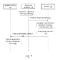
- FIG. 7 is a ladder diagram illustrating an example embodiment of offloading tracking and rendering at a server.
- tracking sensors 112 which are external to the viewing device 101 , generate external tracking data.
- the tracking sensors 112 communicate the external tracking data to the server 110 at operation 704 .
- the server 110 generates augmented reality content based on the external tracking data received at operation 704 .
- the server 110 renders the generated augmented reality content based on the external tracking data.
- the server 110 streams the rendered augmented reality content back to the viewing device 101 .
- the viewing device 101 displays the rendered content.
- FIG. 8 is a flowchart illustrating an example operation for offloading rendering at a server.
- internal tracking data is received from a viewing device 101 at a server 110 .
- augmented reality content is identified and generated at the server 110 based on the internal tracking data.
- augmented reality content is rendered at the server 110 .
- augmented reality content is streamed from the server 110 to the viewing device 101 .
- FIG. 9 is a flowchart illustrating an example operation of offloading tracking at a server 110 .
- external tracking data related to a viewing device 101 are generated at a server 110 .
- the external tracking data is sent from the server 110 to the viewing device 101 .
- augmented reality content is generated at the viewing device 101 based on the external tracking data.
- augmented reality content is rendered at the viewing device 101 .
- FIG. 10 is a flowchart illustrating an example operation of offloading tracking and rendering at a server 110 .
- external tracking data related to a viewing device 101 is generated at a server 110 .
- augmented reality content is generated at the server 110 based on the external tracking data.
- augmented reality content is rendered at the server 110 .
- the rendered augmented reality content is streamed from the server 110 back to the viewing device 101 .
- FIG. 11 is a flowchart illustrating an example operation of adjusting augmented reality content based on updated tracking data at a viewing device 101 .
- a combination of tracking function and rendering function are offloaded from a viewing device 101 to a server 110 .
- augmented reality content is generated at the server 110 based on tracking data.
- augmented reality content is rendered at the server 110 .
- the rendered augmented reality content is streamed from the server 110 back to the viewing device 101 .
- the rendered augmented reality content is adjusted based on the latest tracking data from the viewing device 101 . For example, a position of the rendered augmented reality content is adjusted based on a recent motion of the viewing device 101 .
- Modules may constitute either software modules (e.g., code embodied on a machine-readable medium or in a transmission signal) or hardware modules.
- a hardware module is a tangible unit capable of performing certain operations and may be configured or arranged in a certain manner.
- one or more computer systems e.g., a standalone, client, or server computer system
- one or more hardware modules of a computer system e.g., a processor or a group of processors
- software e.g., an application or application portion
- a hardware module may be implemented mechanically or electronically.
- a hardware module may comprise dedicated circuitry or logic that is permanently configured (e.g., as a special-purpose processor, such as a field programmable gate array (FPGA) or an application-specific integrated circuit (ASIC)) to perform certain operations.
- a hardware module may also comprise programmable logic or circuitry (e.g., as encompassed within a general-purpose processor or other programmable processor) that is temporarily configured by software to perform certain operations. It will be appreciated that the decision to implement a hardware module mechanically, in dedicated and permanently configured circuitry, or in temporarily configured circuitry (e.g., configured by software) may be driven by cost and time considerations.
- the term “hardware module” should be understood to encompass a tangible entity, be that an entity that is physically constructed, permanently configured (e.g., hardwired) or temporarily configured (e.g., programmed) to operate in a certain manner and/or to perform certain operations described herein.
- hardware modules are temporarily configured (e.g., programmed)
- each of the hardware modules need not be configured or instantiated at any one instance in time.
- the hardware modules comprise a general-purpose processor configured using software
- the general-purpose processor may be configured as respective different hardware modules at different times.
- Software may accordingly configure a processor, for example, to constitute a particular hardware module at one instance of time and to constitute a different hardware module at a different instance of time.
- Hardware modules can provide information to, and receive information from, other hardware modules. Accordingly, the described hardware modules may be regarded as being communicatively coupled. Where multiple of such hardware modules exist contemporaneously, communications may be achieved through signal transmission (e.g., over appropriate circuits and buses that connect the hardware modules). In embodiments in which multiple hardware modules are configured or instantiated at different times, communications between such hardware modules may be achieved, for example, through the storage and retrieval of information in memory structures to which the multiple hardware modules have access. For example, one hardware module may perform an operation and store the output of that operation in a memory device to which it is communicatively coupled. A further hardware module may then, at a later time, access the memory device to retrieve and process the stored output. Hardware modules may also initiate communications with input or output devices and can operate on a resource (e.g., a collection of information).
- a resource e.g., a collection of information
- processors may be temporarily configured (e.g., by software) or permanently configured to perform the relevant operations. Whether temporarily or permanently configured, such processors may constitute processor-implemented modules that operate to perform one or more operations or functions.
- the modules referred to herein may, in some example embodiments, comprise processor-implemented modules.
- the methods described herein may be at least partially processor-implemented. For example, at least some of the operations of a method may be performed by one or more processors or processor-implemented modules. The performance of certain of the operations may be distributed among the one or more processors, not only residing within a single machine, but deployed across a number of machines. In some example embodiments, the processor or processors may be located in a single location (e.g., within a home environment, an office environment or as a server farm), while in other embodiments the processors may be distributed across a number of locations.
- the one or more processors may also operate to support performance of the relevant operations in a “cloud computing” environment or as a “software as a service” (SaaS). For example, at least some of the operations may be performed by a group of computers (as examples of machines including processors), these operations being accessible via a network 108 and via one or more appropriate interfaces (e.g., APIs).
- SaaS software as a service
- Example embodiments may be implemented in digital electronic circuitry, or in computer hardware, firmware, software, or in combinations of them.
- Example embodiments may be implemented using a computer program product, e.g., a computer program tangibly embodied in an information carrier, e.g., in a machine-readable medium for execution by, or to control the operation of, data processing apparatus, e.g., a programmable processor, a computer, or multiple computers.
- a computer program can be written in any form of programming language, including compiled or interpreted languages, and it can be deployed in any form, including as a stand-alone program or as a module, subroutine, or other unit suitable for use in a computing environment.
- a computer program can be deployed to be executed on one computer or on multiple computers at one site or distributed across multiple sites and interconnected by a communication network.
- operations may be performed by one or more programmable processors executing a computer program to perform functions by operating on input data and generating output.
- Method operations can also be performed by, and apparatus of example embodiments may be implemented as, special purpose logic circuitry (e.g., a FPGA or an ASIC).
- a computing system can include clients and servers.
- a client and server are generally remote from each other and typically interact through a communication network. The relationship of client and server arises by virtue of computer programs running on the respective computers and having a client-server relationship to each other.
- both hardware and software architectures merit consideration. Specifically, it will be appreciated that the choice of whether to implement certain functionality in permanently configured hardware (e.g., an ASIC), in temporarily configured hardware (e.g., a combination of software and a programmable processor), or a combination of permanently and temporarily configured hardware may be a design choice.
- hardware e.g., machine
- software architectures that may be deployed, in various example embodiments.
- FIG. 12 is a block diagram of a machine in the example form of a computer system 1200 within which instructions for causing the machine to perform any one or more of the methodologies discussed herein may be executed.
- the machine operates as a standalone device or may be connected (e.g., networked) to other machines.
- the machine may operate in the capacity of a server 110 or a client machine in a server-client network environment, or as a peer machine in a peer-to-peer (or distributed) network environment.
- the machine may be a personal computer (PC), a tablet PC, a set-top box (STB), a personal digital assistant (PDA), a cellular telephone, a web appliance, a network router, switch or bridge, or any machine capable of executing instructions (sequential or otherwise) that specify actions to be taken by that machine.
- PC personal computer
- PDA personal digital assistant
- STB set-top box
- WPA personal digital assistant
- cellular telephone a cellular telephone
- web appliance a web appliance
- network router switch or bridge
- machine any machine capable of executing instructions (sequential or otherwise) that specify actions to be taken by that machine.
- machine shall also be taken to include any collection of machines that individually or jointly execute a set (or multiple sets) of instructions to perform any one or more of the methodologies discussed herein.
- the example computer system 1200 includes a processor 1202 (e.g., a central processing unit (CPU), a graphics processing unit (GPU) or both), a main memory 1204 and a static memory 1206 , which communicate with each other via a bus 1208 .
- the computer system 1200 may further include a video display unit 1210 (e.g., a liquid crystal display (LCD) or a cathode ray tube (CRT)).
- the computer system 1200 also includes an alphanumeric input device 1212 (e.g., a keyboard), a user interface (UI) navigation (or cursor control) device 1214 (e.g., a mouse), a disk drive unit 1216 , a signal generation device 1218 (e.g., a speaker) and a network interface device 1220 .
- an alphanumeric input device 1212 e.g., a keyboard
- UI user interface
- cursor control device 1214 e.g., a mouse
- disk drive unit 1216 e.g., a disk drive unit 1216
- signal generation device 1218 e.g., a speaker
- network interface device 1220 e.g., a network interface device
- the disk drive unit 1216 includes a machine-readable medium 1222 on which is stored one or more sets of data structures and instructions 1224 (e.g., software) embodying or utilized by any one or more of the methodologies or functions described herein.
- the instructions 1224 may also reside, completely or at least partially, within the main memory 1204 and/or within the processor 1202 during execution thereof by the computer system 1200 , the main memory 1204 and the processor 1202 also constituting machine-readable media.
- the instructions 1224 may also reside, completely or at least partially, within the static memory 1206 .
- machine-readable medium 1222 is shown in an example embodiment to be a single medium, the term “machine-readable medium” may include a single medium or multiple media (e.g., a centralized or distributed database, and/or associated caches and servers) that store the one or more instructions 1224 or data structures.
- the term “machine-readable medium” shall also be taken to include any tangible medium that is capable of storing, encoding or carrying instructions 1224 for execution by the machine and that cause the machine to perform any one or more of the methodologies of the present embodiments, or that is capable of storing, encoding or carrying data structures utilized by or associated with such instructions 1224 .
- the term “machine-readable medium” shall accordingly be taken to include, but not be limited to, solid-state memories, and optical and magnetic media.
- machine-readable media 1222 include non-volatile memory, including by way of example semiconductor memory devices (e.g., erasable programmable read-only memory (EPROM), electrically erasable programmable read-only memory (EEPROM), and flash memory devices); magnetic disks such as internal hard disks and removable disks; magneto-optical disks; and compact disc-read-only memory (CD-ROM) and digital versatile disc (or digital video disc) read-only memory (DVD-ROM) disks.
- semiconductor memory devices e.g., erasable programmable read-only memory (EPROM), electrically erasable programmable read-only memory (EEPROM), and flash memory devices
- EPROM erasable programmable read-only memory
- EEPROM electrically erasable programmable read-only memory
- flash memory devices e.g., electrically erasable programmable read-only memory (EEPROM), and flash memory devices
- magnetic disks such as internal hard disks and removable disks
- the instructions 1224 may further be transmitted or received over a communications network 1226 using a transmission medium.
- the instructions 1224 may be transmitted using the network interface device 1220 and any one of a number of well-known transfer protocols (e.g., HTTP). Examples of communication networks include a LAN, a WAN, the Internet, mobile telephone networks, POTS networks, and wireless data networks (e.g., WiFi and WiMax networks).
- the term “transmission medium” shall be taken to include any intangible medium capable of storing, encoding, or carrying instructions 1224 for execution by the machine, and includes digital or analog communications signals or other intangible media to facilitate communication of such software.
- FIG. 13 is a block diagram illustrating a mobile device 1300 , according to an example embodiment.
- the mobile device 1300 may include a processor 1302 .
- the processor 1302 may be any of a variety of different types of commercially available processors 1302 suitable for mobile devices 1300 (for example, an XScale architecture microprocessor, a microprocessor without interlocked pipeline stages (MIPS) architecture processor, or another type of processor 1302 ).
- a memory 1304 such as a random access memory (RAM), a flash memory, or other type of memory, is typically accessible to the processor 1302 .
- RAM random access memory
- flash memory or other type of memory
- the memory 1304 may be adapted to store an operating system (OS) 1306 , as well as application programs 1308 , such as a mobile location enabled application that may provide LBSs to a user 102 .
- the processor 1302 may be coupled, either directly or via appropriate intermediary hardware, to a display 1310 and to one or more input/output (I/O) devices 1312 , such as a keypad, a touch panel sensor, a microphone, and the like.
- the processor 1302 may be coupled to a transceiver 1314 that interfaces with an antenna 1316 .
- the transceiver 1314 may be configured to both transmit and receive cellular network signals, wireless data signals, or other types of signals via the antenna 1316 , depending on the nature of the mobile device 1300 . Further, in some configurations, a GPS receiver 1318 may also make use of the antenna 1316 to receive GPS signals.
- inventive subject matter may be referred to herein, individually and/or collectively, by the term “invention” merely for convenience and without intending to voluntarily limit the scope of this application to any single invention or inventive concept if more than one is in fact disclosed.
- inventive concept merely for convenience and without intending to voluntarily limit the scope of this application to any single invention or inventive concept if more than one is in fact disclosed.
Abstract
Description
Claims (18)
Priority Applications (3)
| Application Number | Priority Date | Filing Date | Title |
|---|---|---|---|
| US15/041,437 US9672660B2 (en) | 2013-12-30 | 2016-02-11 | Offloading augmented reality processing |
| US15/592,939 US9990759B2 (en) | 2013-12-30 | 2017-05-11 | Offloading augmented reality processing |
| US15/974,998 US10586395B2 (en) | 2013-12-30 | 2018-05-09 | Remote object detection and local tracking using visual odometry |
Applications Claiming Priority (2)
| Application Number | Priority Date | Filing Date | Title |
|---|---|---|---|
| US14/144,359 US9264479B2 (en) | 2013-12-30 | 2013-12-30 | Offloading augmented reality processing |
| US15/041,437 US9672660B2 (en) | 2013-12-30 | 2016-02-11 | Offloading augmented reality processing |
Related Parent Applications (1)
| Application Number | Title | Priority Date | Filing Date |
|---|---|---|---|
| US14/144,359 Continuation US9264479B2 (en) | 2013-12-30 | 2013-12-30 | Offloading augmented reality processing |
Related Child Applications (1)
| Application Number | Title | Priority Date | Filing Date |
|---|---|---|---|
| US15/592,939 Continuation US9990759B2 (en) | 2013-12-30 | 2017-05-11 | Offloading augmented reality processing |
Publications (2)
| Publication Number | Publication Date |
|---|---|
| US20160163112A1 US20160163112A1 (en) | 2016-06-09 |
| US9672660B2 true US9672660B2 (en) | 2017-06-06 |
Family
ID=53483272
Family Applications (3)
| Application Number | Title | Priority Date | Filing Date |
|---|---|---|---|
| US14/144,359 Expired - Fee Related US9264479B2 (en) | 2013-12-30 | 2013-12-30 | Offloading augmented reality processing |
| US15/041,437 Active US9672660B2 (en) | 2013-12-30 | 2016-02-11 | Offloading augmented reality processing |
| US15/592,939 Active US9990759B2 (en) | 2013-12-30 | 2017-05-11 | Offloading augmented reality processing |
Family Applications Before (1)
| Application Number | Title | Priority Date | Filing Date |
|---|---|---|---|
| US14/144,359 Expired - Fee Related US9264479B2 (en) | 2013-12-30 | 2013-12-30 | Offloading augmented reality processing |
Family Applications After (1)
| Application Number | Title | Priority Date | Filing Date |
|---|---|---|---|
| US15/592,939 Active US9990759B2 (en) | 2013-12-30 | 2017-05-11 | Offloading augmented reality processing |
Country Status (3)
| Country | Link |
|---|---|
| US (3) | US9264479B2 (en) |
| EP (1) | EP3090409A4 (en) |
| WO (1) | WO2015102834A1 (en) |
Cited By (4)
| Publication number | Priority date | Publication date | Assignee | Title |
|---|---|---|---|---|
| US20170115488A1 (en) * | 2015-10-26 | 2017-04-27 | Microsoft Technology Licensing, Llc | Remote rendering for virtual images |
| US9990759B2 (en) | 2013-12-30 | 2018-06-05 | Daqri, Llc | Offloading augmented reality processing |
| US10565464B2 (en) | 2017-12-21 | 2020-02-18 | At&T Intellectual Property I, L.P. | Adaptive cloud offloading of mobile augmented reality |
| US10586395B2 (en) | 2013-12-30 | 2020-03-10 | Daqri, Llc | Remote object detection and local tracking using visual odometry |
Families Citing this family (39)
| Publication number | Priority date | Publication date | Assignee | Title |
|---|---|---|---|---|
| JP2015184778A (en) * | 2014-03-20 | 2015-10-22 | コニカミノルタ株式会社 | Augmented reality display system, augmented reality information generation device, augmented reality display device, server, augmented reality information generation program, augmented reality display program, and data structure of augmented reality information |
| EP3132379B1 (en) | 2014-04-15 | 2018-11-07 | Huntington Ingalls Incorporated | System and method for augmented reality display of dynamic environment information |
| US9864909B2 (en) | 2014-04-25 | 2018-01-09 | Huntington Ingalls Incorporated | System and method for using augmented reality display in surface treatment procedures |
| US9734403B2 (en) | 2014-04-25 | 2017-08-15 | Huntington Ingalls Incorporated | Augmented reality display of dynamic target object information |
| WO2015191346A1 (en) | 2014-06-09 | 2015-12-17 | Huntington Ingalls Incorporated | System and method for augmented reality display of electrical system information |
| US10915754B2 (en) | 2014-06-09 | 2021-02-09 | Huntington Ingalls Incorporated | System and method for use of augmented reality in outfitting a dynamic structural space |
| US10504294B2 (en) | 2014-06-09 | 2019-12-10 | Huntington Ingalls Incorporated | System and method for augmented reality discrepancy determination and reporting |
| WO2016011149A1 (en) * | 2014-07-16 | 2016-01-21 | Huntington Ingalls Incorporated | System and method for augmented reality display of hoisting and rigging information |
| US10954729B2 (en) | 2015-08-31 | 2021-03-23 | Helmerich & Payne Technologies, Llc | System and method for estimating cutting volumes on shale shakers |
| JP2017191378A (en) * | 2016-04-11 | 2017-10-19 | 富士通テン株式会社 | Augmented reality information display device and augmented reality information display method |
| US10366290B2 (en) * | 2016-05-11 | 2019-07-30 | Baidu Usa Llc | System and method for providing augmented virtual reality content in autonomous vehicles |
| US10981060B1 (en) | 2016-05-24 | 2021-04-20 | Out of Sight Vision Systems LLC | Collision avoidance system for room scale virtual reality system |
| DE102016118647B4 (en) * | 2016-09-30 | 2018-12-06 | Deutsche Telekom Ag | Augmented reality communication system and augmented reality interaction device |
| US11164378B1 (en) * | 2016-12-08 | 2021-11-02 | Out of Sight Vision Systems LLC | Virtual reality detection and projection system for use with a head mounted display |
| DE102016125459B3 (en) * | 2016-12-22 | 2018-05-03 | Spintower Kg | Image acquisition method on an image capture system |
| US11164351B2 (en) * | 2017-03-02 | 2021-11-02 | Lp-Research Inc. | Augmented reality for sensor applications |
| US10545456B2 (en) | 2017-04-17 | 2020-01-28 | 8i Limited | Hologram location |
| GB201714349D0 (en) | 2017-09-06 | 2017-10-18 | Xyz Reality Ltd | A method and equipment for setting out a construction site |
| CN110119199B (en) * | 2018-02-07 | 2022-05-10 | 宏达国际电子股份有限公司 | Tracking system, method and non-transitory computer readable medium for real-time rendering of images |
| US11354815B2 (en) * | 2018-05-23 | 2022-06-07 | Samsung Electronics Co., Ltd. | Marker-based augmented reality system and method |
| KR102236957B1 (en) | 2018-05-24 | 2021-04-08 | 티엠알더블유 파운데이션 아이피 앤드 홀딩 에스에이알엘 | System and method for developing, testing and deploying digital reality applications into the real world via a virtual world |
| CN110531846B (en) | 2018-05-24 | 2023-05-23 | 卡兰控股有限公司 | Bi-directional real-time 3D interaction of real-time 3D virtual objects within a real-time 3D virtual world representation real-world |
| DE102018209377A1 (en) | 2018-06-12 | 2019-12-12 | Volkswagen Aktiengesellschaft | A method of presenting AR / VR content on a mobile terminal and mobile terminal presenting AR / VR content |
| WO2020086594A1 (en) * | 2018-10-22 | 2020-04-30 | Motive Drilling Technologies, Inc. | Systems and methods for oilfield drilling operations using computer vision |
| GB2579406A (en) * | 2018-11-30 | 2020-06-24 | Thales Holdings Uk Plc | Remote detector and display |
| US10810430B2 (en) | 2018-12-27 | 2020-10-20 | At&T Intellectual Property I, L.P. | Augmented reality with markerless, context-aware object tracking |
| US11120682B2 (en) * | 2019-02-20 | 2021-09-14 | Robert Bosch Gmbh | System and method for operating physical entities based on a virtual representation of the physical entities |
| US11302055B2 (en) * | 2019-04-01 | 2022-04-12 | Apple Inc. | Distributed processing in computer generated reality system |
| CN111973979A (en) | 2019-05-23 | 2020-11-24 | 明日基金知识产权控股有限公司 | Live management of the real world via a persistent virtual world system |
| CN112102499A (en) | 2019-06-18 | 2020-12-18 | 明日基金知识产权控股有限公司 | Fused reality system and method |
| US11516296B2 (en) * | 2019-06-18 | 2022-11-29 | THE CALANY Holding S.ÀR.L | Location-based application stream activation |
| US11546721B2 (en) * | 2019-06-18 | 2023-01-03 | The Calany Holding S.À.R.L. | Location-based application activation |
| CN112102498A (en) | 2019-06-18 | 2020-12-18 | 明日基金知识产权控股有限公司 | System and method for virtually attaching applications to dynamic objects and enabling interaction with dynamic objects |
| US11341727B2 (en) | 2019-06-18 | 2022-05-24 | The Calany Holding S. À R.L. | Location-based platform for multiple 3D engines for delivering location-based 3D content to a user |
| CN112102497A (en) | 2019-06-18 | 2020-12-18 | 明日基金知识产权控股有限公司 | System and method for attaching applications and interactions to static objects |
| CN112100798A (en) | 2019-06-18 | 2020-12-18 | 明日基金知识产权控股有限公司 | System and method for deploying virtual copies of real-world elements into persistent virtual world systems |
| US11196842B2 (en) | 2019-09-26 | 2021-12-07 | At&T Intellectual Property I, L.P. | Collaborative and edge-enhanced augmented reality systems |
| GB2592040B (en) * | 2020-02-13 | 2022-10-12 | Advanced Risc Mach Ltd | Method and System for Providing Augmented Reality Displays |
| US11363119B1 (en) * | 2020-12-03 | 2022-06-14 | Wormhole Labs, Inc. | Remote processing of augmented reality workloads |
Citations (22)
| Publication number | Priority date | Publication date | Assignee | Title |
|---|---|---|---|---|
| US20040257444A1 (en) * | 2003-06-18 | 2004-12-23 | Matsushita Electric Industrial Co., Ltd. | Video surveillance system, surveillance video composition apparatus, and video surveillance server |
| US20060240808A1 (en) * | 2005-04-20 | 2006-10-26 | Sbc Knowledge Ventures, L.P. | System and method of providing advertisements to cellular devices |
| US20070061101A1 (en) * | 2005-09-13 | 2007-03-15 | Ibm Corporation | Input device for providing position information to information handling systems |
| US20070066323A1 (en) * | 2005-09-22 | 2007-03-22 | Korea Advanced Institute Of Science And Technology | Intuitive real spatial aiming-based system, identification and communication methods using the same |
| US20080071559A1 (en) * | 2006-09-19 | 2008-03-20 | Juha Arrasvuori | Augmented reality assisted shopping |
| US20090102859A1 (en) | 2007-10-18 | 2009-04-23 | Yahoo! Inc. | User augmented reality for camera-enabled mobile devices |
| US20100045662A1 (en) | 2006-10-02 | 2010-02-25 | Aftercad Software Inc. | Method and system for delivering and interactively displaying three-dimensional graphics |
| US20110231781A1 (en) | 2010-03-19 | 2011-09-22 | International Business Machines Corporation | System and method for virtual object sharing and management in virtual worlds |
| US20110246276A1 (en) | 2010-04-02 | 2011-10-06 | Richard Ross Peters | Augmented- reality marketing with virtual coupon |
| US20120114297A1 (en) | 2010-11-08 | 2012-05-10 | Suranajit Adhikari | Augmented reality system for communicating tagged video and data on a network |
| US20120212405A1 (en) | 2010-10-07 | 2012-08-23 | Benjamin Zeis Newhouse | System and method for presenting virtual and augmented reality scenes to a user |
| US20130091239A1 (en) * | 2011-10-07 | 2013-04-11 | Verizon Patent And Licensing Inc. | Optimizing selection of a network for video streaming |
| US20130113993A1 (en) * | 2011-11-04 | 2013-05-09 | Remote TelePointer, LLC | Method and system for user interface for interactive devices using a mobile device |
| WO2013093906A1 (en) | 2011-09-19 | 2013-06-27 | Eyesight Mobile Technologies Ltd. | Touch free interface for augmented reality systems |
| US20130178257A1 (en) * | 2012-01-06 | 2013-07-11 | Augaroo, Inc. | System and method for interacting with virtual objects in augmented realities |
| US20130198176A1 (en) | 2012-01-26 | 2013-08-01 | Lg Electronics Inc. | Mobile terminal and photo searching method thereof |
| US20140002496A1 (en) | 2012-06-29 | 2014-01-02 | Mathew J. Lamb | Constraint based information inference |
| US20140016820A1 (en) | 2012-07-12 | 2014-01-16 | Palo Alto Research Center Incorporated | Distributed object tracking for augmented reality application |
| US20140173674A1 (en) * | 2012-12-13 | 2014-06-19 | Microsoft Corporation | Server gpu assistance for mobile gpu applications |
| US20150032838A1 (en) | 2013-07-29 | 2015-01-29 | Aol Advertising Inc. | Systems and methods for caching augmented reality target data at user devices |
| US20150188984A1 (en) | 2013-12-30 | 2015-07-02 | Daqri, Llc | Offloading augmented reality processing |
| US9338622B2 (en) * | 2012-10-04 | 2016-05-10 | Bernt Erik Bjontegard | Contextually intelligent communication systems and processes |
Family Cites Families (11)
| Publication number | Priority date | Publication date | Assignee | Title |
|---|---|---|---|---|
| JP3406965B2 (en) * | 2000-11-24 | 2003-05-19 | キヤノン株式会社 | Mixed reality presentation device and control method thereof |
| US20150070262A1 (en) * | 2005-09-21 | 2015-03-12 | Richard Ross Peters | Contextual annotations of a message based on user eye-tracking data |
| JP5047090B2 (en) * | 2008-07-31 | 2012-10-10 | キヤノン株式会社 | system |
| US20100208029A1 (en) * | 2009-02-13 | 2010-08-19 | Samsung Electronics Co., Ltd | Mobile immersive display system |
| WO2011013910A2 (en) * | 2009-07-30 | 2011-02-03 | 에스케이텔레콤 주식회사 | Method for providing augmented reality, server for same, and portable terminal |
| JP5960796B2 (en) * | 2011-03-29 | 2016-08-02 | クアルコム,インコーポレイテッド | Modular mobile connected pico projector for local multi-user collaboration |
| US9600933B2 (en) * | 2011-07-01 | 2017-03-21 | Intel Corporation | Mobile augmented reality system |
| GB2501567A (en) * | 2012-04-25 | 2013-10-30 | Christian Sternitzke | Augmented reality information obtaining system |
| US9082149B2 (en) * | 2013-02-19 | 2015-07-14 | Wal-Mart Stores, Inc. | System and method for providing sales assistance to a consumer wearing an augmented reality device in a physical store |
| US9607584B2 (en) * | 2013-03-15 | 2017-03-28 | Daqri, Llc | Real world analytics visualization |
| US9686466B1 (en) * | 2013-06-27 | 2017-06-20 | Google Inc. | Systems and methods for environment content sharing |
-
2013
- 2013-12-30 US US14/144,359 patent/US9264479B2/en not_active Expired - Fee Related
-
2014
- 2014-12-10 WO PCT/US2014/069536 patent/WO2015102834A1/en active Application Filing
- 2014-12-10 EP EP14875991.3A patent/EP3090409A4/en not_active Withdrawn
-
2016
- 2016-02-11 US US15/041,437 patent/US9672660B2/en active Active
-
2017
- 2017-05-11 US US15/592,939 patent/US9990759B2/en active Active
Patent Citations (24)
| Publication number | Priority date | Publication date | Assignee | Title |
|---|---|---|---|---|
| US20040257444A1 (en) * | 2003-06-18 | 2004-12-23 | Matsushita Electric Industrial Co., Ltd. | Video surveillance system, surveillance video composition apparatus, and video surveillance server |
| US20060240808A1 (en) * | 2005-04-20 | 2006-10-26 | Sbc Knowledge Ventures, L.P. | System and method of providing advertisements to cellular devices |
| US20070061101A1 (en) * | 2005-09-13 | 2007-03-15 | Ibm Corporation | Input device for providing position information to information handling systems |
| US20070066323A1 (en) * | 2005-09-22 | 2007-03-22 | Korea Advanced Institute Of Science And Technology | Intuitive real spatial aiming-based system, identification and communication methods using the same |
| US20080071559A1 (en) * | 2006-09-19 | 2008-03-20 | Juha Arrasvuori | Augmented reality assisted shopping |
| US20100045662A1 (en) | 2006-10-02 | 2010-02-25 | Aftercad Software Inc. | Method and system for delivering and interactively displaying three-dimensional graphics |
| US20090102859A1 (en) | 2007-10-18 | 2009-04-23 | Yahoo! Inc. | User augmented reality for camera-enabled mobile devices |
| US20110231781A1 (en) | 2010-03-19 | 2011-09-22 | International Business Machines Corporation | System and method for virtual object sharing and management in virtual worlds |
| US20110246276A1 (en) | 2010-04-02 | 2011-10-06 | Richard Ross Peters | Augmented- reality marketing with virtual coupon |
| US20120212405A1 (en) | 2010-10-07 | 2012-08-23 | Benjamin Zeis Newhouse | System and method for presenting virtual and augmented reality scenes to a user |
| US20120114297A1 (en) | 2010-11-08 | 2012-05-10 | Suranajit Adhikari | Augmented reality system for communicating tagged video and data on a network |
| WO2013093906A1 (en) | 2011-09-19 | 2013-06-27 | Eyesight Mobile Technologies Ltd. | Touch free interface for augmented reality systems |
| US20130091239A1 (en) * | 2011-10-07 | 2013-04-11 | Verizon Patent And Licensing Inc. | Optimizing selection of a network for video streaming |
| US20130113993A1 (en) * | 2011-11-04 | 2013-05-09 | Remote TelePointer, LLC | Method and system for user interface for interactive devices using a mobile device |
| US20130178257A1 (en) * | 2012-01-06 | 2013-07-11 | Augaroo, Inc. | System and method for interacting with virtual objects in augmented realities |
| US20130198176A1 (en) | 2012-01-26 | 2013-08-01 | Lg Electronics Inc. | Mobile terminal and photo searching method thereof |
| US20140002496A1 (en) | 2012-06-29 | 2014-01-02 | Mathew J. Lamb | Constraint based information inference |
| US20140016820A1 (en) | 2012-07-12 | 2014-01-16 | Palo Alto Research Center Incorporated | Distributed object tracking for augmented reality application |
| US9338622B2 (en) * | 2012-10-04 | 2016-05-10 | Bernt Erik Bjontegard | Contextually intelligent communication systems and processes |
| US20140173674A1 (en) * | 2012-12-13 | 2014-06-19 | Microsoft Corporation | Server gpu assistance for mobile gpu applications |
| US20150032838A1 (en) | 2013-07-29 | 2015-01-29 | Aol Advertising Inc. | Systems and methods for caching augmented reality target data at user devices |
| US20150188984A1 (en) | 2013-12-30 | 2015-07-02 | Daqri, Llc | Offloading augmented reality processing |
| WO2015102834A1 (en) | 2013-12-30 | 2015-07-09 | Daqri, Llc | Offloading augmented reality processing |
| US9264479B2 (en) * | 2013-12-30 | 2016-02-16 | Daqri, Llc | Offloading augmented reality processing |
Non-Patent Citations (6)
Cited By (5)
| Publication number | Priority date | Publication date | Assignee | Title |
|---|---|---|---|---|
| US9990759B2 (en) | 2013-12-30 | 2018-06-05 | Daqri, Llc | Offloading augmented reality processing |
| US10586395B2 (en) | 2013-12-30 | 2020-03-10 | Daqri, Llc | Remote object detection and local tracking using visual odometry |
| US20170115488A1 (en) * | 2015-10-26 | 2017-04-27 | Microsoft Technology Licensing, Llc | Remote rendering for virtual images |
| US10962780B2 (en) * | 2015-10-26 | 2021-03-30 | Microsoft Technology Licensing, Llc | Remote rendering for virtual images |
| US10565464B2 (en) | 2017-12-21 | 2020-02-18 | At&T Intellectual Property I, L.P. | Adaptive cloud offloading of mobile augmented reality |
Also Published As
| Publication number | Publication date |
|---|---|
| US9264479B2 (en) | 2016-02-16 |
| WO2015102834A1 (en) | 2015-07-09 |
| US20160163112A1 (en) | 2016-06-09 |
| EP3090409A4 (en) | 2017-08-23 |
| EP3090409A1 (en) | 2016-11-09 |
| US9990759B2 (en) | 2018-06-05 |
| US20150188984A1 (en) | 2015-07-02 |
| US20170249774A1 (en) | 2017-08-31 |
Similar Documents
| Publication | Publication Date | Title |
|---|---|---|
| US9990759B2 (en) | Offloading augmented reality processing | |
| US10586395B2 (en) | Remote object detection and local tracking using visual odometry | |
| US9898844B2 (en) | Augmented reality content adapted to changes in real world space geometry | |
| US11341652B2 (en) | Three-dimensional mapping system | |
| US9626801B2 (en) | Visualization of physical characteristics in augmented reality | |
| US20150185825A1 (en) | Assigning a virtual user interface to a physical object | |
| US9978174B2 (en) | Remote sensor access and queuing | |
| US10198869B2 (en) | Remote expert system | |
| US20150187137A1 (en) | Physical object discovery | |
| US20160054791A1 (en) | Navigating augmented reality content with a watch | |
| US9799142B2 (en) | Spatial data collection | |
| US20180005440A1 (en) | Universal application programming interface for augmented reality | |
| US20160227868A1 (en) | Removable face shield for augmented reality device |
Legal Events
| Date | Code | Title | Description |
|---|---|---|---|
| AS | Assignment |
Owner name: DAQRI, LLC, CALIFORNIA Free format text: ASSIGNMENT OF ASSIGNORS INTEREST;ASSIGNOR:MULLINS, BRIAN;REEL/FRAME:038945/0069 Effective date: 20140613 |
|
| STCF | Information on status: patent grant |
Free format text: PATENTED CASE |
|
| AS | Assignment |
Owner name: AR HOLDINGS I LLC, NEW JERSEY Free format text: SECURITY INTEREST;ASSIGNOR:DAQRI, LLC;REEL/FRAME:049596/0965 Effective date: 20190604 |
|
| AS | Assignment |
Owner name: SCHWEGMAN, LUNDBERG & WOESSNER, P.A., MINNESOTA Free format text: LIEN;ASSIGNOR:DAQRI, LLC;REEL/FRAME:050672/0601 Effective date: 20191007 |
|
| AS | Assignment |
Owner name: DAQRI, LLC, CALIFORNIA Free format text: RELEASE BY SECURED PARTY;ASSIGNOR:SCHWEGMAN, LUNDBERG & WOESSNER, P.A.;REEL/FRAME:050805/0606 Effective date: 20191023 |
|
| FEPP | Fee payment procedure |
Free format text: ENTITY STATUS SET TO UNDISCOUNTED (ORIGINAL EVENT CODE: BIG.); ENTITY STATUS OF PATENT OWNER: LARGE ENTITY |
|
| AS | Assignment |
Owner name: RPX CORPORATION, CALIFORNIA Free format text: ASSIGNMENT OF ASSIGNORS INTEREST;ASSIGNOR:DAQRI, LLC;REEL/FRAME:053413/0642 Effective date: 20200615 |
|
| AS | Assignment |
Owner name: JEFFERIES FINANCE LLC, AS COLLATERAL AGENT, NEW YORK Free format text: PATENT SECURITY AGREEMENT;ASSIGNOR:RPX CORPORATION;REEL/FRAME:053498/0095 Effective date: 20200729 Owner name: DAQRI, LLC, CALIFORNIA Free format text: RELEASE BY SECURED PARTY;ASSIGNOR:AR HOLDINGS I, LLC;REEL/FRAME:053498/0580 Effective date: 20200615 |
|
| AS | Assignment |
Owner name: BARINGS FINANCE LLC, AS COLLATERAL AGENT, NORTH CAROLINA Free format text: PATENT SECURITY AGREEMENT;ASSIGNORS:RPX CLEARINGHOUSE LLC;RPX CORPORATION;REEL/FRAME:054198/0029 Effective date: 20201023 Owner name: BARINGS FINANCE LLC, AS COLLATERAL AGENT, NORTH CAROLINA Free format text: PATENT SECURITY AGREEMENT;ASSIGNORS:RPX CLEARINGHOUSE LLC;RPX CORPORATION;REEL/FRAME:054244/0566 Effective date: 20200823 |
|
| AS | Assignment |
Owner name: RPX CORPORATION, CALIFORNIA Free format text: RELEASE BY SECURED PARTY;ASSIGNOR:JEFFERIES FINANCE LLC;REEL/FRAME:054486/0422 Effective date: 20201023 |
|
| MAFP | Maintenance fee payment |
Free format text: PAYMENT OF MAINTENANCE FEE, 4TH YEAR, LARGE ENTITY (ORIGINAL EVENT CODE: M1551); ENTITY STATUS OF PATENT OWNER: LARGE ENTITY Year of fee payment: 4 |
|
| AS | Assignment |
Owner name: FACEBOOK TECHNOLOGIES, LLC, CALIFORNIA Free format text: ASSIGNMENT OF ASSIGNORS INTEREST;ASSIGNOR:RPX CORPORATION;REEL/FRAME:056777/0588 Effective date: 20210514 |
|
| AS | Assignment |
Owner name: META PLATFORMS TECHNOLOGIES, LLC, CALIFORNIA Free format text: CHANGE OF NAME;ASSIGNOR:FACEBOOK TECHNOLOGIES, LLC;REEL/FRAME:060936/0494 Effective date: 20220318 |