US9681830B2 - Device and method for detecting a vital parameter - Google Patents
Device and method for detecting a vital parameter Download PDFInfo
- Publication number
- US9681830B2 US9681830B2 US13/081,186 US201113081186A US9681830B2 US 9681830 B2 US9681830 B2 US 9681830B2 US 201113081186 A US201113081186 A US 201113081186A US 9681830 B2 US9681830 B2 US 9681830B2
- Authority
- US
- United States
- Prior art keywords
- light
- light source
- sensor arrangement
- finger
- optoelectronic sensor
- Prior art date
- Legal status (The legal status is an assumption and is not a legal conclusion. Google has not performed a legal analysis and makes no representation as to the accuracy of the status listed.)
- Expired - Fee Related, expires
Links
Images


Classifications
-
- A—HUMAN NECESSITIES
- A61—MEDICAL OR VETERINARY SCIENCE; HYGIENE
- A61B—DIAGNOSIS; SURGERY; IDENTIFICATION
- A61B5/00—Measuring for diagnostic purposes; Identification of persons
- A61B5/145—Measuring characteristics of blood in vivo, e.g. gas concentration, pH value; Measuring characteristics of body fluids or tissues, e.g. interstitial fluid, cerebral tissue
- A61B5/1455—Measuring characteristics of blood in vivo, e.g. gas concentration, pH value; Measuring characteristics of body fluids or tissues, e.g. interstitial fluid, cerebral tissue using optical sensors, e.g. spectral photometrical oximeters
- A61B5/14551—Measuring characteristics of blood in vivo, e.g. gas concentration, pH value; Measuring characteristics of body fluids or tissues, e.g. interstitial fluid, cerebral tissue using optical sensors, e.g. spectral photometrical oximeters for measuring blood gases
-
- A—HUMAN NECESSITIES
- A61—MEDICAL OR VETERINARY SCIENCE; HYGIENE
- A61B—DIAGNOSIS; SURGERY; IDENTIFICATION
- A61B2560/00—Constructional details of operational features of apparatus; Accessories for medical measuring apparatus
- A61B2560/02—Operational features
- A61B2560/0204—Operational features of power management
- A61B2560/0209—Operational features of power management adapted for power saving
-
- A—HUMAN NECESSITIES
- A61—MEDICAL OR VETERINARY SCIENCE; HYGIENE
- A61B—DIAGNOSIS; SURGERY; IDENTIFICATION
- A61B5/00—Measuring for diagnostic purposes; Identification of persons
- A61B5/68—Arrangements of detecting, measuring or recording means, e.g. sensors, in relation to patient
- A61B5/6887—Arrangements of detecting, measuring or recording means, e.g. sensors, in relation to patient mounted on external non-worn devices, e.g. non-medical devices
- A61B5/6893—Cars
Definitions
- the present invention relates to devices and methods for detecting a vital parameter and, for example, to the control of optoelectronic sensor arrangements used for this purpose.
- the methods of optical plethysmography and pulse oxymetry are methods for a none invasive determination of vital parameters of a living being, e.g., of the pulse rate, the pulse rate variability and the arterial oxygen saturation, by measuring a light absorption or a light remission in the tissue of the living being.
- the oxygen saturation values or SpO 2 values are tapped via an optical sensor at the finger, toe or earlobe, wherein measuring is executed by means of a clip sensor or an adhesive sensor.
- optical plethysmography and pulse oxymetry for detecting such vital parameters may, however, also be executed under automobile conditions, i.e., in a automobile or a vehicle, for example by integrating the optical sensors into operating elements of the vehicle. This enables a detection of the vital parameters with little adverse effects on the driver.
- One possible implementation is the integration of the optical sensor into a gear level knob of the vehicle.
- the sensors typically consist of two light sources, e.g., a red diode and an infrared diode and a photo sensor or photodiode. As soon as the optical sensor is switched on, the two diodes light up.
- the infrared diode radiates in the non visible range of the electromagnetic spectrum, in contrast to that the red diode radiates in the visible range of the electromagnetic spectrum. On the one hand this may distract the driver and on the other hand it may negatively affect the light design of the interior of the vehicle, e.g., when the predominant color is green or blue.
- a device for detecting a vital parameter may have an optoelectronic sensor arrangement for detecting the vital parameter by means of light remission, wherein the optoelectronic sensor arrangement comprises a first light source for generating light in a visible wavelength range, a second light source for generating light in a non-visible wavelength range and a light sensitive element; and a control means which is implemented to switch on the second light source in temporal intervals, execute an evaluation of the light received from the light-sensitive element in the invisible wavelength range of the second light source with respect to whether a finger is applied to the optoelectronic sensor arrangement and to switch on the first light source as soon as the evaluation indicates that a finger is applied to the optoelectronic sensor arrangement.
- a method may have the step of detecting a vital parameter by means of an optoelectronic sensor arrangement for detecting the vital parameter by means of light remission, wherein the optoelectronic sensor arrangement comprises a first light source for generating light in the visible wavelength range, a second light source for generating light in a non-visible wavelength range and a light-sensitive element, and wherein the method may further have the steps of switching on the second light source in temporal intervals; evaluating the light received from the light-sensitive element in the invisible wavelength range of the second light source with respect to whether a finger is applied to the optoelectronic sensor arrangement; and switching on the first light source as soon as the evaluation indicates that a finger is applied to the optoelectronic sensor arrangement.
- a device for detecting a vital parameter may have an optoelectronic sensor arrangement for detecting the vital parameter by means of light remission at a finger, wherein the optoelectronic sensor arrangement comprises a first light source for generating light in a visible wavelength range, a second light source for generating light in a non-visible wavelength range and a light sensitive element; and a controller which is implemented to switch on the second light source in temporal intervals, execute an evaluation of the light received from the light-sensitive element in the invisible wavelength range of the second light source with respect to whether a finger is applied to the optoelectronic sensor arrangement and to switch on a first light source as soon as the evaluation indicates that a finger is applied to the optoelectronic sensor arrangement, wherein the controller is implemented to execute an evaluation over a temporal course of the light received from the light sensitive element in the invisible wavelength range of the second light source to detect a pulse parameter when a finger is applied to the optoelectronic sensor arrangement and to switch on the first light source
- the operation of the sensor is made optically invisible for the user.
- the continuous operation of the active sensor module which includes two light emitting diodes when the finger is not applied, may lead to the impairment of the driver on the one hand and, on the other hand, of the light design in the vehicle interior. These effects are in particular disturbing in the hours of evening and night.
- Embodiments of the present invention cause the switch-off of the diode emitting the visible light at times at which no finger is applied to the optoelectronic sensor arrangement or to the active sensor module. This way the disturbing impairment of driver and light design may effectively be prevented.
- the overall energy consumption of the transmitter is reduced.
- a red diode forms an embodiment for the first light source which is implemented to generate light in the visible wavelength range or in the visible electromagnetic spectrum
- an infrared diode forms an embodiment for the second light source which is implemented to generate light in the non-visible wave length range or in the non-visible electromagnetic spectrum
- a photosensor or a photodiode forms an embodiment for a light-sensitive element.
- the term “vital parameter” is a generic term for medical parameters such as e.g., for blood oxygen saturation, the pulse, the electrocardiogram (ECG), the temperature, muscle tension, blood sugar content or blood pressure.
- ECG electrocardiogram
- a difference may be made between the pulse parameters or pulse information of pulse wave, pulse frequency, pulse amplitude, shape of the pulse wave and/or the speed of propagation of the pulse wave.
- Embodiments of the invention thus, also relate to a technical solution for controlling the switch-on arrangement of an optical sensor for the detection of a pulse wave, pulse rate, a pulse rate variability and an oxygen saturation of the blood of a driver of a vehicle.
- Fields of application of the embodiments are, for example, in the field of preventive, monitoring and attending medicine for the use in a vehicle, e.g., as a driver assistance system.
- FIG. 1 shows a block diagram of an embodiment of a device for detecting a vital parameter with an optoelectronic sensor arrangement and a control means.
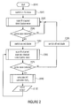
- FIG. 2 shows a flow chart of an embodiment of a method for detecting a vital parameter.
- FIGS. 3A to 3D show exemplary courses of original signals and signals generated therefrom by means of morphological non-linear operators.
- a continuous activation of the first light source generating light in the visible wave length range would disturb the driver, in particular in the hours of evening and night and/or disturb the light design of the vehicle interior.
- a sensor for detecting a vital parameter which comprises a red and an infrared diode as light sources, and a photosensor or a photodiode as a light-sensitive element.
- the light sources and the photosensor are, for example, arranged in the same plane and are arranged close to each other.
- the light sources radiate their light into the tissue of the finger and the photosensor measures the reflected, remitted portions of the light field.
- the tissue is continuously supplied with blood, wherein circulation is not constant but varies with time in the form of the pulse waves.
- the blood has the characteristic to absorb the light differently in different wavelengths.
- the degree of absorption of the light field or the reflected portion of the light field in the temporal course provides information on the pulse waves in the tissue.
- the determination of the absorption degree of only one light wavelength is sufficient, i.e., in the visible or non-visible wavelength range.
- two light wavelengths or the determination of the absorption degree for two light wavelengths are needed.
- FIG. 1 shows a block diagram of an embodiment of a device 1100 for detecting a vital parameter comprising an optoelectronic sensor arrangement 1130 and a control means 1410 .
- the control means 1410 is coupled to the optoelectronic sensor arrangement, wherein the control means 1410 is implemented to activate or deactivate, or enable or disable the first light source 1310 or the second light source 1320 (see arrows from the control means 1410 to the first light source and second light source 1310 , 1320 ), and is implemented to receive a signal from the light sensitive element 1330 comprising information on the intensity or light intensity of the received light.
- the signal is for example a voltage output by the light sensitive element and which depends in a known ratio on the light intensity of the incoming light.
- the optoelectronic sensor arrangement 1130 is implemented to detect the vital parameter by means of light remission as it was already described above.
- the optoelectronic sensor arrangement 1130 comprises a first light source 1310 for generating light in a visible wavelength range, a second light source 1320 for generating light in a non-visible wavelength range or a wavelength range invisible for humans and a light sensitive element 1330 for receiving a portion of the light of the first and second light source 1310 , 1320 reflected and remitted in a finger or in general for receiving a light in the wavelength range in which the first light source 1310 generates the visible light and the second light source generates the non-visible light.
- the control means 1410 is implemented to switch on the second light source 1320 in temporal intervals to execute an evaluation of the light received from the light-sensitive element in the invisible wavelength range of the second light source with respect to whether a finger is applied to the optoelectronic sensor arrangement 1130 , and to switch on the first light source 1310 as soon as the evaluation indicates that a finger is applied to the optoelectronic sensor arrangement 1130 .
- the temporal intervals in which the second light source is switched on may be periodic, periodic with a fixed period or a decreasing period length, wherein the period duration or length decreases with time that passed since the last detection, or any other temporal intervals.
- control means 1410 are implemented to switch off the first light source as soon as the above-mentioned evaluation indicates that no finger is applied to the optoelectronic sensor arrangement 1130 .
- control means 1410 are implemented to execute the above mentioned evaluation over a time period of the light, received from the light-sensitive element 1130 , in the non-visible wavelength range of the second light source in order to detect a pulse parameter, e.g. a pulse wave, when a finger is applied to the optoelectronic sensor arrangement 1130 , and accordingly switch on the first light source when the pulse parameter is detected.
- a pulse parameter e.g. a pulse wave
- control means 1410 is for example implemented to detect the pulse wave itself, detect its special form (by means of corresponding evaluation algorithms), detect the frequency and/or pulse amplitude of the pulse or in general the presence of a signal, which allows a conclusion to the presence of a pulse and thus to a finger or similar things applied to the sensor arrangement 1130 .
- a) detecting a pulse or applying a finger when the signal 1132 comprises a certain number of zero crossings per time unit b) detecting a minimum when falling below a minimum threshold value and a maximum when exceeding a maximum threshold value, wherein the temporal distance between the minimum and the maximum lies below a temporal threshold value, c) detecting a steepness of the increase, i.e.
- a maximum speed of increase of the signal amplitude of the previously lowpass filtered signal by means of detecting the maximum of the first deviation of the previously lowpass filtered temporal signal d) detection of the significant signal structures with a known width, with the help of so-called opening operators and closing operators of a morphological analysis of the time signal, and e) analysis of the spectral density estimation, i.e. a weighting of the frequency portions.
- FIG. 3A shows the course of the original signal 310 and the signal 310 ′ generated therefrom after erosion or after executing the erosion operation.
- the dilatation operator determines, for each value of a digital signal f 320 , the maximum of the surrounding M signal values and allocates the same as a new value. By this, positive signal ranges are expanded and negative signal ranges are removed.
- FIG. 3B shows an example of a course of an original signal 320 and a signal generated therefrom after the dilatation or after executing the dilatation operation.
- FIG. 3C shows a course of an original signal 330 and the signal 330 ′ generated therefrom after executing the opening operation.
- FIG. 3D shows the course of an original signal 340 and the signal 340 ′ generated by applying a closing operation to the output signal 340 , after “closing”.
- the present invention further provides a method for detecting a vital parameter by means of an optoelectronic sensor arrangement 1130 as it was described before, for example with reference to FIG. 1 .
- the method here comprises the steps explained in the following.
- the disclosures according to the device for detecting a vital parameter apply.
- the light remission sensor or the optoelectronic sensor arrangement 1130 is integrated in a gear level knob of a vehicle.
- the infrared diode 1320 is switched on simultaneously with the sensor 1130 .
- the signal from the measurement photodiode 1330 is continuously requested or scanned and evaluated to be able to determine whether the finger of the driver is positioned opposite the optical sensor 1130 and the pulse waves may be detected.
- the red diode is additionally switched on and the standard routine for the pulse oxymetric measurement is requested. At this time, the finger is placed opposite the optical sensor 1130 and the red light of the red diode is shielded.
- the algorithm further continues the polling routine at the infrared channel.
- step 2010 the device 1100 or the method for detecting a vital parameter is started and in step 2020 the infrared diode (IR diode) is switched on together with the optoelectronic sensor arrangement 1130 .
- step 2030 the infrared channel (IR channel) or the signal 1132 of the light sensitive element is scanned and, as described above, evaluated for example to detect a pulse wave as an indication whether a finger is applied. It is tested in step 2040 whether a pulse wave was detected. If no pulse wave was detected (no), step 2030 is repeated. If a pulse wave is detected (yes), in step 2050 the red diode 1310 is switched on and in step 2060 the infrared channel (IR channel) and the red channel are scanned.
- step 2060 It is further tested in step 2060 whether further a pulse wave is detected (step 2070 ). If no pulse wave is detected (no), in step 2080 the red diode 1310 is switched off again and the method continues with step 2030 . If further a pulse wave is detected (yes), the standard routine for the pulse oxymetric measurement in step 2090 is executed. Here, for example, based on the scanned infrared and red light or the signal 1132 of the light sensitive element resulting therefrom the pulse rate or heart rate HR and/or the oxygen saturation SpO 2 of the blood are calculated, i.e. in other words the standard routine for measuring the one or several vital parameters is executed. In step 2100 these values or vital parameters are then output, for example to a driver information system or to a doctor's PC. After step 2100 the method continues with step 2060 and the same is repeated until no pulse wave is detected.
- embodiments also provide a “switch-on device of an optical sensor for detecting a pulse wave of the driver in the gear lever knob” and/or a “method for controlling an optical sensor for the detection of the pulse wave of the driver in the gear lever knob”.
- the operation of the sensor is made optically invisible for the user or driver.
- the embodiments of the inventive method may be implemented in hardware or in software.
- the implementation may be executed on a digital storage medium, in particular a floppy disk, CD or DVD having electronically readable control signals which may cooperate with a programmable computer system so that one of the embodiments of the inventive methods is executed.
- the embodiments of the present invention also consist in software program products or computer program products or program products having a program code stored on a machine readable carrier for executing an embodiment of the inventive method, when one of the software program products is executed on a computer or on a processor.
- an embodiment of the present invention may thus be realized as a computer program or software program or program having a program code for executing an embodiment of an inventive method, when the program is executed on a processor.
- the processor may be formed by a computer, a chip card, a digital signal processor or another integrated circuitry.
Applications Claiming Priority (7)
| Application Number | Priority Date | Filing Date | Title |
|---|---|---|---|
| DE102008050638.9 | 2008-10-07 | ||
| DE102008050638 | 2008-10-07 | ||
| DE102008050638 | 2008-10-07 | ||
| DE102008056251 | 2008-11-06 | ||
| DE102008056251.3 | 2008-11-06 | ||
| DE102008056251A DE102008056251A1 (de) | 2008-10-07 | 2008-11-06 | Vorrichtung und Verfahren zum Erfassen eines Vitalparameters |
| PCT/EP2009/006875 WO2010040451A1 (fr) | 2008-10-07 | 2009-09-23 | Dispositif et procédé pour détecter un paramètre vital |
Related Parent Applications (1)
| Application Number | Title | Priority Date | Filing Date |
|---|---|---|---|
| PCT/EP2009/006875 Continuation WO2010040451A1 (fr) | 2008-10-07 | 2009-09-23 | Dispositif et procédé pour détecter un paramètre vital |
Publications (2)
| Publication Number | Publication Date |
|---|---|
| US20110237912A1 US20110237912A1 (en) | 2011-09-29 |
| US9681830B2 true US9681830B2 (en) | 2017-06-20 |
Family
ID=41821353
Family Applications (1)
| Application Number | Title | Priority Date | Filing Date |
|---|---|---|---|
| US13/081,186 Expired - Fee Related US9681830B2 (en) | 2008-10-07 | 2011-04-06 | Device and method for detecting a vital parameter |
Country Status (6)
| Country | Link |
|---|---|
| US (1) | US9681830B2 (fr) |
| EP (1) | EP2355693B1 (fr) |
| CN (1) | CN102238898B (fr) |
| DE (1) | DE102008056251A1 (fr) |
| ES (1) | ES2402949T3 (fr) |
| WO (1) | WO2010040451A1 (fr) |
Cited By (3)
| Publication number | Priority date | Publication date | Assignee | Title |
|---|---|---|---|---|
| US20190059797A1 (en) * | 2017-08-31 | 2019-02-28 | Fuji Xerox Co., Ltd. | Optical measuring apparatus and non-transitory computer readable medium |
| US11765827B2 (en) | 2005-03-04 | 2023-09-19 | Sanmina Corporation | Simultaneous and selective wide gap partitioning of via structures using plating resist |
| US11793467B2 (en) | 2017-03-28 | 2023-10-24 | Apple Inc. | Detecting conditions using heart rate sensors |
Families Citing this family (19)
| Publication number | Priority date | Publication date | Assignee | Title |
|---|---|---|---|---|
| US10216893B2 (en) | 2010-09-30 | 2019-02-26 | Fitbit, Inc. | Multimode sensor devices |
| US20130100043A1 (en) * | 2011-10-24 | 2013-04-25 | General Electric Company | Method for determining valid touch screen inputs |
| DE102011086740A1 (de) * | 2011-11-21 | 2013-05-23 | Zf Friedrichshafen Ag | Erfassungsvorrichtung zur Erfassung von Vitalparametern |
| US9241643B2 (en) | 2012-05-31 | 2016-01-26 | Covidien Lp | Methods and systems for power optimization in a medical device |
| US9241676B2 (en) | 2012-05-31 | 2016-01-26 | Covidien Lp | Methods and systems for power optimization in a medical device |
| US9005129B2 (en) | 2012-06-22 | 2015-04-14 | Fitbit, Inc. | Wearable heart rate monitor |
| US9049998B2 (en) * | 2012-06-22 | 2015-06-09 | Fitbit, Inc. | Biometric monitoring device with heart rate measurement activated by a single user-gesture |
| US8948832B2 (en) * | 2012-06-22 | 2015-02-03 | Fitbit, Inc. | Wearable heart rate monitor |
| US9039614B2 (en) | 2013-01-15 | 2015-05-26 | Fitbit, Inc. | Methods, systems and devices for measuring fingertip heart rate |
| US9125606B2 (en) * | 2013-03-13 | 2015-09-08 | Koninklijke Philips N.V. | Device and method for determining the blood oxygen saturation of a subject |
| US10512407B2 (en) | 2013-06-24 | 2019-12-24 | Fitbit, Inc. | Heart rate data collection |
| EP3125755A1 (fr) * | 2014-03-31 | 2017-02-08 | Koninklijke Philips N.V. | Dispositif, système et procédé permettant de déterminer des signes vitaux d'un sujet |
| CN104875744B (zh) * | 2015-04-28 | 2017-09-12 | 奇瑞汽车股份有限公司 | 驾驶员身体状态监测方法及系统 |
| CN104856697B (zh) * | 2015-06-15 | 2017-09-22 | 康泰医学系统(秦皇岛)股份有限公司 | 反射式血氧仪手指识别方法 |
| US11206989B2 (en) | 2015-12-10 | 2021-12-28 | Fitbit, Inc. | Light field management in an optical biological parameter sensor |
| US10568525B1 (en) | 2015-12-14 | 2020-02-25 | Fitbit, Inc. | Multi-wavelength pulse oximetry |
| FR3048173B1 (fr) | 2016-02-29 | 2018-03-16 | Commissariat A L'energie Atomique Et Aux Energies Alternatives | Procede d’estimation d’une frequence cardiaque et dispositif associe |
| EP3448249A4 (fr) | 2016-04-29 | 2019-10-09 | Fitbit, Inc. | Détecteur multi-canal de photopléthysmographie |
| US11051706B1 (en) | 2017-04-07 | 2021-07-06 | Fitbit, Inc. | Multiple source-detector pair photoplethysmography (PPG) sensor |
Citations (43)
| Publication number | Priority date | Publication date | Assignee | Title |
|---|---|---|---|---|
| US3911899A (en) | 1973-11-08 | 1975-10-14 | Chemetron Corp | Respiration monitoring method and apparatus |
| US4122427A (en) | 1976-06-24 | 1978-10-24 | Herbert Karsh | Motion monitor |
| US4773422A (en) | 1987-04-30 | 1988-09-27 | Nonin Medical, Inc. | Single channel pulse oximeter |
| DE3723880A1 (de) | 1987-07-18 | 1989-01-26 | Nicolay Gmbh | Optoelektronische vorrichtung zum durchstrahlen lebenden gewebes |
| US4967751A (en) | 1988-05-04 | 1990-11-06 | Mmtc, Inc. | Apparatus and method for monitoring the waveform of cyclic movement within the thorax of an individual |
| WO1996013208A1 (fr) | 1994-11-01 | 1996-05-09 | Masimo Corporation | Sonde optique a faible bruit |
| US5746697A (en) * | 1996-02-09 | 1998-05-05 | Nellcor Puritan Bennett Incorporated | Medical diagnostic apparatus with sleep mode |
| US5792052A (en) | 1994-06-29 | 1998-08-11 | Nonin Medical, Inc. | Finger clip pulse oximeter |
| WO1998035118A1 (fr) | 1997-02-06 | 1998-08-13 | Siemens Aktiengesellschaft | Systeme d'identification |
| US5825293A (en) | 1996-09-20 | 1998-10-20 | Ahmed; Adel A. | Apparatus and method for monitoring breathing magnetically |
| DE29901849U1 (de) | 1999-02-03 | 1999-04-08 | Merlaku Kastriot | Anti-Einschlaf-System für Fahrzeug-Führer |
| JP2001245871A (ja) | 2000-03-07 | 2001-09-11 | Kazumasa Onodera | 動脈血酸素飽和度を居眠り判定法に用いた居眠り判定装置 |
| JP2001260698A (ja) | 2000-03-21 | 2001-09-26 | Isuzu Motors Ltd | 心拍呼吸検出装置 |
| US6439333B2 (en) | 2000-03-23 | 2002-08-27 | Siemens Aktiengesellschaft | Sensor system and method for determining the position of vehicle occupants in vehicles |
| US6513164B1 (en) | 2001-09-14 | 2003-02-04 | Renee Burnadette Hearns | Baby blanket assembly |
| US20030036685A1 (en) | 2000-04-27 | 2003-02-20 | Vitalsines International, Inc. | Physiological signal monitoring system |
| US20030208109A1 (en) | 2000-05-18 | 2003-11-06 | Daniel David | Chair and ancillary apparatus with medical diagnostic features in a remote health monitoring system |
| GB2390460A (en) | 2002-06-08 | 2004-01-07 | Imagination Station Ltd | Vehicle driver tiredness alarm |
| US6697658B2 (en) * | 2001-07-02 | 2004-02-24 | Masimo Corporation | Low power pulse oximeter |
| DE10249415B3 (de) | 2002-10-23 | 2004-03-25 | Siemens Ag | System zur medizinischen Unterstützung der Insassen eines Kraftfahrzeugs |
| US20040077937A1 (en) | 2002-10-21 | 2004-04-22 | Remon Medical Technologies Ltd | Apparatus and method for coupling a medical device to a body surface |
| US20040245344A1 (en) | 2003-05-21 | 2004-12-09 | Atmel Germany Gmbh | Integrated circuit for a transponder |
| WO2005009237A1 (fr) | 2003-07-28 | 2005-02-03 | Hitachi, Ltd. | Dispositif de detection de somnolence et dispositif d'authentification de personne |
| US20050084075A1 (en) | 2003-10-15 | 2005-04-21 | Motorola, Inc. | Method and apparatus for selecting an alert mode based on user biometrics |
| DE102004007253B3 (de) | 2004-02-10 | 2005-06-09 | Takata-Petri Ag | Lenkrad für ein Kraftfahrzeug und Verfahren unter Verwendung eines derartigen Lenkrades |
| DE102004010554A1 (de) | 2004-03-04 | 2005-09-22 | Cm Electronic Gmbh | Fingerabdruck-Aufnahmegerät |
| US20050239075A1 (en) | 2003-04-03 | 2005-10-27 | Pioneer Corporation | Living body information detecting device, contact member used therefor, and living body information detecting member-use paint |
| US20060009685A1 (en) | 2004-07-08 | 2006-01-12 | Orsense Ltd. | Device and method for non-invasive optical measurements |
| EP1632371A1 (fr) | 2004-09-06 | 2006-03-08 | Hitachi Ltd. | Climatisation pour habitale |
| US20060058595A1 (en) | 2003-03-13 | 2006-03-16 | Vera Herrmann | Blood optode |
| EP1661511A1 (fr) | 2003-09-02 | 2006-05-31 | Matsushita Electric Industrial Co., Ltd. | Capteur biologique et systeme de soutien l'utilisant |
| US20060250275A1 (en) | 2003-06-18 | 2006-11-09 | Klaus Rodemer | Sensor arrangement for applying to a belt, especially to a safety belt of a motor vehicle |
| CA2517184A1 (fr) | 2005-08-25 | 2007-02-25 | Groupe Procycle | Capteur optique pour equipement sportif |
| DE102005059687A1 (de) | 2005-12-14 | 2007-06-21 | Daimlerchrysler Ag | Vorrichtung zum Überwachen des Zustands eines Fahrers |
| DE102006005664A1 (de) | 2006-02-06 | 2007-08-09 | Ahlers, Horst, Dr. | Überwachung des Gesundheitszustandes eines Fahrzeugführers |
| DE202006012071U1 (de) | 2006-05-05 | 2007-09-20 | Mevitec Gmbh | Vorrichtung zur optischen Untersuchung eines biologischen Gewebes |
| US20080103702A1 (en) | 2006-10-30 | 2008-05-01 | Aisin Seiki Kabushiki Kaisha | Biosignal intensity distribution measuring apparatus and biosignal intensity distribution measuring method |
| US20080243018A1 (en) | 2007-03-30 | 2008-10-02 | General Electric Company | System and method to track a respiratory cycle of a subject |
| US7499740B2 (en) * | 2004-02-25 | 2009-03-03 | Nellcor Puritan Bennett Llc | Techniques for detecting heart pulses and reducing power consumption in sensors |
| US20090082989A1 (en) | 2007-09-24 | 2009-03-26 | General Electric Company | System and method for improving the distortion tolerance of an electromagnetic tracking system |
| US7673354B2 (en) | 2005-08-30 | 2010-03-09 | Sarath Fader | Baby sleeping pouch method and apparatus |
| US20100240972A1 (en) * | 2009-03-20 | 2010-09-23 | Nellcor Puritan Bennett Llc | Slider Spot Check Pulse Oximeter |
| US20110218409A1 (en) | 2010-03-04 | 2011-09-08 | Andreas Kugler | Device and method for measuring sleep apneas |
Family Cites Families (12)
| Publication number | Priority date | Publication date | Assignee | Title |
|---|---|---|---|---|
| US4258718A (en) * | 1979-04-16 | 1981-03-31 | Goldman Michael D | Measuring respiratory air volume |
| US5327117A (en) * | 1991-03-22 | 1994-07-05 | Omron Corporation | Adaptive message display apparatus |
| US5769085A (en) * | 1993-01-06 | 1998-06-23 | Mitsubishi Jidosha Kogyo Kabushiki Kaisha | Apparatus for detecting awareness of a vehicle driver and method thereof |
| US6100811A (en) * | 1997-12-22 | 2000-08-08 | Trw Inc. | Fingerprint actuation of customized vehicle features |
| US6445303B1 (en) * | 2000-06-23 | 2002-09-03 | Michael Aryeh | Apparatus and method for producing an electric shock to wake sleeping drivers |
| US7265663B2 (en) * | 2001-11-28 | 2007-09-04 | Trivinci Systems, Llc | Multimedia racing experience system |
| US6927671B2 (en) * | 2002-09-03 | 2005-08-09 | Debono Joseph M. | Biometric shifter lock control |
| ATE391978T1 (de) * | 2003-05-08 | 2008-04-15 | Koninkl Philips Electronics Nv | Notfallmeldesystem, notfallmeldesystem ermöglichendes körperliches netz, verfahren zur meldung einer notlage und fahrzeug ausgestattet mit einem notfallmeldesystem |
| US20060093192A1 (en) * | 2004-11-03 | 2006-05-04 | Bechtel J S | Finger guide device |
| CN100544669C (zh) * | 2007-11-22 | 2009-09-30 | 河南华南医电科技有限公司 | 一种睡眠呼吸障碍检测装置 |
| US20090174560A1 (en) * | 2008-01-03 | 2009-07-09 | General Electric Company | Systems, Apparatuses And Methods For Monitoring Physical Conditions Of A Vehicle Driver |
| KR20130050113A (ko) * | 2011-11-07 | 2013-05-15 | 현대자동차주식회사 | 위험단계별 경고기능을 갖는 차량 운행보조 시스템 및 그 방법 |
-
2008
- 2008-11-06 DE DE102008056251A patent/DE102008056251A1/de not_active Withdrawn
-
2009
- 2009-09-23 EP EP09778675A patent/EP2355693B1/fr not_active Not-in-force
- 2009-09-23 ES ES09778675T patent/ES2402949T3/es active Active
- 2009-09-23 CN CN2009801482899A patent/CN102238898B/zh not_active Expired - Fee Related
- 2009-09-23 WO PCT/EP2009/006875 patent/WO2010040451A1/fr active Application Filing
-
2011
- 2011-04-06 US US13/081,186 patent/US9681830B2/en not_active Expired - Fee Related
Patent Citations (46)
| Publication number | Priority date | Publication date | Assignee | Title |
|---|---|---|---|---|
| US3911899A (en) | 1973-11-08 | 1975-10-14 | Chemetron Corp | Respiration monitoring method and apparatus |
| US4122427A (en) | 1976-06-24 | 1978-10-24 | Herbert Karsh | Motion monitor |
| US4773422A (en) | 1987-04-30 | 1988-09-27 | Nonin Medical, Inc. | Single channel pulse oximeter |
| DE3723880A1 (de) | 1987-07-18 | 1989-01-26 | Nicolay Gmbh | Optoelektronische vorrichtung zum durchstrahlen lebenden gewebes |
| US4967751A (en) | 1988-05-04 | 1990-11-06 | Mmtc, Inc. | Apparatus and method for monitoring the waveform of cyclic movement within the thorax of an individual |
| US5792052A (en) | 1994-06-29 | 1998-08-11 | Nonin Medical, Inc. | Finger clip pulse oximeter |
| WO1996013208A1 (fr) | 1994-11-01 | 1996-05-09 | Masimo Corporation | Sonde optique a faible bruit |
| US5746697A (en) * | 1996-02-09 | 1998-05-05 | Nellcor Puritan Bennett Incorporated | Medical diagnostic apparatus with sleep mode |
| US5825293A (en) | 1996-09-20 | 1998-10-20 | Ahmed; Adel A. | Apparatus and method for monitoring breathing magnetically |
| WO1998035118A1 (fr) | 1997-02-06 | 1998-08-13 | Siemens Aktiengesellschaft | Systeme d'identification |
| DE29901849U1 (de) | 1999-02-03 | 1999-04-08 | Merlaku Kastriot | Anti-Einschlaf-System für Fahrzeug-Führer |
| JP2001245871A (ja) | 2000-03-07 | 2001-09-11 | Kazumasa Onodera | 動脈血酸素飽和度を居眠り判定法に用いた居眠り判定装置 |
| JP2001260698A (ja) | 2000-03-21 | 2001-09-26 | Isuzu Motors Ltd | 心拍呼吸検出装置 |
| US6439333B2 (en) | 2000-03-23 | 2002-08-27 | Siemens Aktiengesellschaft | Sensor system and method for determining the position of vehicle occupants in vehicles |
| US20030036685A1 (en) | 2000-04-27 | 2003-02-20 | Vitalsines International, Inc. | Physiological signal monitoring system |
| US20030208109A1 (en) | 2000-05-18 | 2003-11-06 | Daniel David | Chair and ancillary apparatus with medical diagnostic features in a remote health monitoring system |
| US6832987B2 (en) | 2000-05-18 | 2004-12-21 | Cardiomedix, Inc. | Chair and ancillary apparatus with medical diagnostic features in a remote health monitoring system |
| US6697658B2 (en) * | 2001-07-02 | 2004-02-24 | Masimo Corporation | Low power pulse oximeter |
| US6513164B1 (en) | 2001-09-14 | 2003-02-04 | Renee Burnadette Hearns | Baby blanket assembly |
| GB2390460A (en) | 2002-06-08 | 2004-01-07 | Imagination Station Ltd | Vehicle driver tiredness alarm |
| US20040077937A1 (en) | 2002-10-21 | 2004-04-22 | Remon Medical Technologies Ltd | Apparatus and method for coupling a medical device to a body surface |
| DE10249415B3 (de) | 2002-10-23 | 2004-03-25 | Siemens Ag | System zur medizinischen Unterstützung der Insassen eines Kraftfahrzeugs |
| US20040133082A1 (en) | 2002-10-23 | 2004-07-08 | Klaus Abraham-Fuchs | System for medically assisting the occupants of a motor vehicle |
| US20060058595A1 (en) | 2003-03-13 | 2006-03-16 | Vera Herrmann | Blood optode |
| US20050239075A1 (en) | 2003-04-03 | 2005-10-27 | Pioneer Corporation | Living body information detecting device, contact member used therefor, and living body information detecting member-use paint |
| US20040245344A1 (en) | 2003-05-21 | 2004-12-09 | Atmel Germany Gmbh | Integrated circuit for a transponder |
| US20060250275A1 (en) | 2003-06-18 | 2006-11-09 | Klaus Rodemer | Sensor arrangement for applying to a belt, especially to a safety belt of a motor vehicle |
| WO2005009237A1 (fr) | 2003-07-28 | 2005-02-03 | Hitachi, Ltd. | Dispositif de detection de somnolence et dispositif d'authentification de personne |
| EP1661511A1 (fr) | 2003-09-02 | 2006-05-31 | Matsushita Electric Industrial Co., Ltd. | Capteur biologique et systeme de soutien l'utilisant |
| US20050084075A1 (en) | 2003-10-15 | 2005-04-21 | Motorola, Inc. | Method and apparatus for selecting an alert mode based on user biometrics |
| DE102004007253B3 (de) | 2004-02-10 | 2005-06-09 | Takata-Petri Ag | Lenkrad für ein Kraftfahrzeug und Verfahren unter Verwendung eines derartigen Lenkrades |
| US7499740B2 (en) * | 2004-02-25 | 2009-03-03 | Nellcor Puritan Bennett Llc | Techniques for detecting heart pulses and reducing power consumption in sensors |
| DE102004010554A1 (de) | 2004-03-04 | 2005-09-22 | Cm Electronic Gmbh | Fingerabdruck-Aufnahmegerät |
| US20060009685A1 (en) | 2004-07-08 | 2006-01-12 | Orsense Ltd. | Device and method for non-invasive optical measurements |
| EP1632371A1 (fr) | 2004-09-06 | 2006-03-08 | Hitachi Ltd. | Climatisation pour habitale |
| CA2517184A1 (fr) | 2005-08-25 | 2007-02-25 | Groupe Procycle | Capteur optique pour equipement sportif |
| US7673354B2 (en) | 2005-08-30 | 2010-03-09 | Sarath Fader | Baby sleeping pouch method and apparatus |
| DE102005059687A1 (de) | 2005-12-14 | 2007-06-21 | Daimlerchrysler Ag | Vorrichtung zum Überwachen des Zustands eines Fahrers |
| DE102006005664A1 (de) | 2006-02-06 | 2007-08-09 | Ahlers, Horst, Dr. | Überwachung des Gesundheitszustandes eines Fahrzeugführers |
| DE202006012071U1 (de) | 2006-05-05 | 2007-09-20 | Mevitec Gmbh | Vorrichtung zur optischen Untersuchung eines biologischen Gewebes |
| US20080103702A1 (en) | 2006-10-30 | 2008-05-01 | Aisin Seiki Kabushiki Kaisha | Biosignal intensity distribution measuring apparatus and biosignal intensity distribution measuring method |
| US20080243018A1 (en) | 2007-03-30 | 2008-10-02 | General Electric Company | System and method to track a respiratory cycle of a subject |
| DE102008016286A1 (de) | 2007-03-30 | 2008-10-02 | General Electric Company | System und Verfahren zum Verfolgen eines Atemzyklus eines Objektes |
| US20090082989A1 (en) | 2007-09-24 | 2009-03-26 | General Electric Company | System and method for improving the distortion tolerance of an electromagnetic tracking system |
| US20100240972A1 (en) * | 2009-03-20 | 2010-09-23 | Nellcor Puritan Bennett Llc | Slider Spot Check Pulse Oximeter |
| US20110218409A1 (en) | 2010-03-04 | 2011-09-08 | Andreas Kugler | Device and method for measuring sleep apneas |
Non-Patent Citations (4)
| Title |
|---|
| Hug, Rene; "Le pouls au volat . . . "; Apr. 14, 2005; 2 pages (including translation). |
| Int'l Search Report, mailed Feb. 3, 2010, in related PCT application No. PCT/EP2009/006875, 12 pages. |
| Jeong, in Cheol et al., "Development of Bio Signal Measurement System for Vehicles", 2007 International Conference on Convergence Information Technology, IEEE, Piscataway, NJ, USA, Nov. 21, 2007 (Nov. 21, 2007), p. 1091-1096. |
| Mead, et al., "Pulmonary Ventilation Measured from Body Surface Movements", Science, vol. 156, 1967, pp. 1383-1384. |
Cited By (4)
| Publication number | Priority date | Publication date | Assignee | Title |
|---|---|---|---|---|
| US11765827B2 (en) | 2005-03-04 | 2023-09-19 | Sanmina Corporation | Simultaneous and selective wide gap partitioning of via structures using plating resist |
| US11793467B2 (en) | 2017-03-28 | 2023-10-24 | Apple Inc. | Detecting conditions using heart rate sensors |
| US20190059797A1 (en) * | 2017-08-31 | 2019-02-28 | Fuji Xerox Co., Ltd. | Optical measuring apparatus and non-transitory computer readable medium |
| US11534088B2 (en) * | 2017-08-31 | 2022-12-27 | Fujifilm Business Innovation Corp. | Optical measuring apparatus and non-transitory computer readable medium |
Also Published As
| Publication number | Publication date |
|---|---|
| US20110237912A1 (en) | 2011-09-29 |
| DE102008056251A1 (de) | 2010-04-15 |
| CN102238898A (zh) | 2011-11-09 |
| CN102238898B (zh) | 2013-10-30 |
| ES2402949T3 (es) | 2013-05-10 |
| EP2355693B1 (fr) | 2012-12-19 |
| WO2010040451A1 (fr) | 2010-04-15 |
| EP2355693A1 (fr) | 2011-08-17 |
Similar Documents
| Publication | Publication Date | Title |
|---|---|---|
| US9681830B2 (en) | Device and method for detecting a vital parameter | |
| JP6525890B2 (ja) | 対象者のバイタルサイン情報を決定するためのシステム及び方法 | |
| US9277888B2 (en) | Photon density wave pulse oximetry and pulse hemometry | |
| JP3125079B2 (ja) | パルスオキシメータ | |
| US8855749B2 (en) | Determination of a physiological parameter | |
| US20120165629A1 (en) | Systems and methods of monitoring a patient through frequency-domain photo migration spectroscopy | |
| US20090326395A1 (en) | Systems and methods for detecting pulses | |
| WO2014096353A1 (fr) | Procédés et systèmes pour déterminer le détachement d'une sonde dans un dispositif médical | |
| US11197620B2 (en) | PPG signal collection method and apparatus | |
| US20150245782A1 (en) | Systems and methods for capacitance sensing in medical devices | |
| US9078609B2 (en) | Extraction of physiological measurements from a photoplethysmograph (PPG) signal | |
| JP2019518547A (ja) | バイタルサイン検出に関するシステム及び方法 | |
| RU2680190C1 (ru) | Датчик показателей жизненно важных функций и способ измерения показателей жизненно важных функций пользователя | |
| US20170215747A1 (en) | Optical vital signs sensor | |
| US8433382B2 (en) | Transmission mode photon density wave system and method | |
| US10874317B2 (en) | Biological information measurement device | |
| JPH10337282A (ja) | 反射型酸素飽和度測定装置 | |
| US20090326347A1 (en) | Synchronous Light Detection Utilizing CMOS/CCD Sensors For Oximetry Sensing | |
| CN108420411B (zh) | 信号处理方法及电子设备 | |
| US20160345862A1 (en) | Optical respiration rate detection device and detection method thereof | |
| US20140180042A1 (en) | Methods and Systems for Detecting a Sensor Off Condition Using A Reference Ambient Characteristic | |
| FI3758606T3 (fi) | Menetelmä valonlähteen intensiteetin valitsemiseksi veressä olevan analyytin seuraamiseksi ja laite sitä varten | |
| WO2017133883A1 (fr) | Capteur optique de signes vitaux | |
| US20140275882A1 (en) | Methods and Systems for Determining a Probe-Off Condition in a Medical Device | |
| US20240057868A1 (en) | System for Optically Measuring Vital Parameters |
Legal Events
| Date | Code | Title | Description |
|---|---|---|---|
| AS | Assignment |
Owner name: ZF FRIEDRICHSHAFEN AG, GERMANY Free format text: ASSIGNMENT OF ASSIGNORS INTEREST;ASSIGNORS:COURONNE, ROBERT;CIANCITTO, FABIO;ERSHOV, SERGEY;AND OTHERS;SIGNING DATES FROM 20110516 TO 20110606;REEL/FRAME:026463/0458 Owner name: FRAUNHOFER-GESELLSCHAFT ZUR FOERDERUNG DER ANGEWAN Free format text: ASSIGNMENT OF ASSIGNORS INTEREST;ASSIGNORS:COURONNE, ROBERT;CIANCITTO, FABIO;ERSHOV, SERGEY;AND OTHERS;SIGNING DATES FROM 20110516 TO 20110606;REEL/FRAME:026463/0458 |
|
| STCF | Information on status: patent grant |
Free format text: PATENTED CASE |
|
| FEPP | Fee payment procedure |
Free format text: MAINTENANCE FEE REMINDER MAILED (ORIGINAL EVENT CODE: REM.); ENTITY STATUS OF PATENT OWNER: LARGE ENTITY |
|
| LAPS | Lapse for failure to pay maintenance fees |
Free format text: PATENT EXPIRED FOR FAILURE TO PAY MAINTENANCE FEES (ORIGINAL EVENT CODE: EXP.); ENTITY STATUS OF PATENT OWNER: LARGE ENTITY |
|
| STCH | Information on status: patent discontinuation |
Free format text: PATENT EXPIRED DUE TO NONPAYMENT OF MAINTENANCE FEES UNDER 37 CFR 1.362 |
|
| FP | Lapsed due to failure to pay maintenance fee |
Effective date: 20210620 |