US9692587B2 - Phase tracking - Google Patents

Phase tracking Download PDF

Info

Publication number
US9692587B2
US9692587B2 US14/922,345 US201514922345A US9692587B2 US 9692587 B2 US9692587 B2 US 9692587B2 US 201514922345 A US201514922345 A US 201514922345A US 9692587 B2 US9692587 B2 US 9692587B2
Authority
US
United States
Prior art keywords
samples
correction
packet
symbol
corrected
Prior art date
Legal status (The legal status is an assumption and is not a legal conclusion. Google has not performed a legal analysis and makes no representation as to the accuracy of the status listed.)
Active, expires
Application number
US14/922,345
Other versions
US20170118004A1 (en
Inventor
Bruce L. McKinley
Current Assignee (The listed assignees may be inaccurate. Google has not performed a legal analysis and makes no representation or warranty as to the accuracy of the list.)
Higher Ground LLC
Original Assignee
Higher Ground LLC
Priority date (The priority date is an assumption and is not a legal conclusion. Google has not performed a legal analysis and makes no representation as to the accuracy of the date listed.)
Filing date
Publication date
Application filed by Higher Ground LLC filed Critical Higher Ground LLC
Priority to US14/922,345 priority Critical patent/US9692587B2/en
Assigned to HIGHER GROUND LLC reassignment HIGHER GROUND LLC ASSIGNMENT OF ASSIGNORS INTEREST (SEE DOCUMENT FOR DETAILS). Assignors: MCKINLEY, BRUCE L.
Priority to PCT/US2016/057937 priority patent/WO2017074791A1/en
Publication of US20170118004A1 publication Critical patent/US20170118004A1/en
Application granted granted Critical
Publication of US9692587B2 publication Critical patent/US9692587B2/en
Assigned to REIS, Robert reassignment REIS, Robert SECURITY INTEREST (SEE DOCUMENT FOR DETAILS). Assignors: HIGHER GROUND LLC
Active legal-status Critical Current
Adjusted expiration legal-status Critical

Links

Images

Classifications

    • HELECTRICITY
    • H04ELECTRIC COMMUNICATION TECHNIQUE
    • H04BTRANSMISSION
    • H04B1/00Details of transmission systems, not covered by a single one of groups H04B3/00 - H04B13/00; Details of transmission systems not characterised by the medium used for transmission
    • H04B1/69Spread spectrum techniques
    • H04B1/707Spread spectrum techniques using direct sequence modulation
    • H04B1/7073Synchronisation aspects
    • H04B1/7087Carrier synchronisation aspects
    • HELECTRICITY
    • H04ELECTRIC COMMUNICATION TECHNIQUE
    • H04LTRANSMISSION OF DIGITAL INFORMATION, e.g. TELEGRAPHIC COMMUNICATION
    • H04L7/00Arrangements for synchronising receiver with transmitter
    • H04L7/0016Arrangements for synchronising receiver with transmitter correction of synchronization errors
    • H04L7/002Arrangements for synchronising receiver with transmitter correction of synchronization errors correction by interpolation
    • HELECTRICITY
    • H04ELECTRIC COMMUNICATION TECHNIQUE
    • H04LTRANSMISSION OF DIGITAL INFORMATION, e.g. TELEGRAPHIC COMMUNICATION
    • H04L27/00Modulated-carrier systems
    • H04L27/0014Carrier regulation
    • HELECTRICITY
    • H04ELECTRIC COMMUNICATION TECHNIQUE
    • H04LTRANSMISSION OF DIGITAL INFORMATION, e.g. TELEGRAPHIC COMMUNICATION
    • H04L27/00Modulated-carrier systems
    • H04L27/26Systems using multi-frequency codes
    • H04L27/2601Multicarrier modulation systems
    • H04L27/2602Signal structure
    • H04L27/2605Symbol extensions, e.g. Zero Tail, Unique Word [UW]
    • HELECTRICITY
    • H04ELECTRIC COMMUNICATION TECHNIQUE
    • H04LTRANSMISSION OF DIGITAL INFORMATION, e.g. TELEGRAPHIC COMMUNICATION
    • H04L27/00Modulated-carrier systems
    • H04L27/26Systems using multi-frequency codes
    • H04L27/2601Multicarrier modulation systems
    • H04L27/2602Signal structure
    • H04L27/261Details of reference signals
    • H04L27/2613Structure of the reference signals
    • HELECTRICITY
    • H04ELECTRIC COMMUNICATION TECHNIQUE
    • H04LTRANSMISSION OF DIGITAL INFORMATION, e.g. TELEGRAPHIC COMMUNICATION
    • H04L27/00Modulated-carrier systems
    • H04L27/26Systems using multi-frequency codes
    • H04L27/2601Multicarrier modulation systems
    • H04L27/2647Arrangements specific to the receiver only
    • H04L27/2655Synchronisation arrangements
    • H04L27/2657Carrier synchronisation
    • HELECTRICITY
    • H04ELECTRIC COMMUNICATION TECHNIQUE
    • H04LTRANSMISSION OF DIGITAL INFORMATION, e.g. TELEGRAPHIC COMMUNICATION
    • H04L27/00Modulated-carrier systems
    • H04L27/26Systems using multi-frequency codes
    • H04L27/2601Multicarrier modulation systems
    • H04L27/2647Arrangements specific to the receiver only
    • H04L27/2655Synchronisation arrangements
    • H04L27/2662Symbol synchronisation
    • HELECTRICITY
    • H04ELECTRIC COMMUNICATION TECHNIQUE
    • H04LTRANSMISSION OF DIGITAL INFORMATION, e.g. TELEGRAPHIC COMMUNICATION
    • H04L7/00Arrangements for synchronising receiver with transmitter
    • H04L7/0079Receiver details
    • HELECTRICITY
    • H04ELECTRIC COMMUNICATION TECHNIQUE
    • H04LTRANSMISSION OF DIGITAL INFORMATION, e.g. TELEGRAPHIC COMMUNICATION
    • H04L27/00Modulated-carrier systems
    • H04L27/0014Carrier regulation
    • H04L2027/0044Control loops for carrier regulation
    • H04L2027/0063Elements of loops
    • H04L2027/0067Phase error detectors
    • HELECTRICITY
    • H04ELECTRIC COMMUNICATION TECHNIQUE
    • H04LTRANSMISSION OF DIGITAL INFORMATION, e.g. TELEGRAPHIC COMMUNICATION
    • H04L27/00Modulated-carrier systems
    • H04L27/26Systems using multi-frequency codes
    • H04L27/2601Multicarrier modulation systems
    • H04L27/2647Arrangements specific to the receiver only
    • H04L27/2655Synchronisation arrangements
    • H04L27/2668Details of algorithms
    • H04L27/2673Details of algorithms characterised by synchronisation parameters
    • H04L27/2675Pilot or known symbols

Definitions

  • aspects of the present disclosure may relate to techniques for carrier phase acquisition and tracking in communication systems.
  • Carrier phase acquisition and tracking are common issues in communication systems.
  • an initial carrier phase synchronization may be performed at a receive-end of the communication system.
  • phase tracking can cause the carrier phase to vary throughout a reception, and it is often beneficial to continue to adjust the phase at the receiver (termed “phase tracking”). This may be done, e.g., on a continuous basis, on a periodic basis, or on an as-needed basis (e.g., a process may be triggered when some criterion is satisfied (e.g., error rate or some quality measure falls below a predetermined level)).
  • Phase tracking may be particularly difficult in weak-signal environments, e.g., where the received signal is below a “noise floor” in the band in which it is received (i.e., has a “negative signal-to-noise ratio (SNR),” in decibels).
  • SNR signal-to-noise ratio
  • This may be done deliberately, e.g., using direct-sequence spread-spectrum (DSSS) or other spectral spreading techniques, for example, to avoid interfering with other signals transmitted in the same band, to allow multiple access in the same band, and/or to decrease detectability of the signaling by unintended receivers. It may also occur unintentionally, e.g., due to signal attenuation, intentional or unintentional electromagnetic interference from other sources, etc.
  • DSSS direct-sequence spread-spectrum
  • other spectral spreading techniques for example, to avoid interfering with other signals transmitted in the same band, to allow multiple access in the same band, and/or to decrease
  • One example is the transmission of DSSS signals over satellite links, where the DSSS signals have their energy purposely spread over a wide band (wider, at least, than a bandwidth that would normally be needed to transmit the signals, were they not spread), and where the satellite link may introduce significant attenuation, e.g., where the satellite used is in geosynchronous orbit.
  • Synchronization in phase may be further complicated by the fact that baseband symbol instants are often unknown at the receiver, or may be approximated/extrapolated. In some cases, extrapolation may cause the receiver to extract “timing instants” that occur before the signal has actually arrived at the receiver, and which thus do not actually contain any signal energy. At negative SNRs, if timing instants with no signal energy are used in frequency/phase estimation, they may cause a failure in packet sync correlation. For more traditional approaches (in which extrapolation is not used), the same basic effect may occur when samples without any signal content are fed into a synchronization loop.
  • Typical methods of frequency/phase synchronization may use a phase detector and a phase-locked loop (PLL) connected to some sort of adjustable mixing device.
  • the phase detector may be data-driven, such as using a unique word (UW) sync pattern, or data-independent, such as “power-of-2” estimation.
  • UW unique word
  • power-of-2 data-independent
  • synchronization may be difficult when the symbol energy to noise power spectral density (referred to with the symbol E s /N 0 ) is less than unity, or negative in terms of decibel units.
  • E s /N 0 the symbol energy to noise power spectral density
  • a PLL cannot be used because the loop SNR will be too low to maintain lock. In fact, in such cases it is often difficult to even detect that a signal is present.
  • Pilot-aided acquisition strategies i.e., using pilot tones or symbols
  • pilot information may result in a cost, in terms of data transmission efficiency (in power, bandwidth, time, duty cycle, etc.). For that reason, it may be beneficial to limit the use of pilot information as much as possible.
  • Various aspects of the disclosure may be directed to a three-stage pilot-aided frequency and phase synchronization process that may adjust frequency offset to establish a packet start time; may finely adjust frequency offset once the packet start time is determined; and may track phase variation using a minimal set of received pilot symbols.
  • Various operations may be performed by dedicated electronic hardware devices, or alternatively, may be implemented using other hardware, software, or firmware, or combinations thereof, including the possibility of using a processor that may execute software instructions, which may, e.g., be saved on a storage device, and which may cause the operations to be implemented.
  • FIG. 1 shows a conceptual flow diagram of an example according to an aspect of this disclosure
  • FIG. 2 shows a conceptual flow diagram of a portion of the example of FIG. 1 , according to various aspects of the disclosure
  • FIG. 3 shows a conceptual example of a packet, according to an aspect of the disclosure
  • FIG. 4 shows a conceptual flow diagram of a portion of the example of FIG. 1 , according to various aspects of the disclosure.
  • FIG. 5 shows a conceptual flow diagram of a portion of the example of FIG. 1 , according to various aspects of the disclosure.
  • FIG. 1 shows a conceptual flow diagram of an example according to various aspects of this disclosure.
  • a signal may be received, and candidate symbol sample instants may be obtained from the received signal (not shown); this may be done according to any method.
  • symbol timing/clock phase may still not be certain, e.g., because the start time of a packet containing a set of symbols may not be precisely determined by finding the candidate symbol sample instants (and/or for other reasons, such as clock drift, etc.), and this may lead to erroneous reception.
  • the example of FIG. 1 may be used to more precisely determine and correct carrier frequency and track phase variations throughout the reception. According to the example of FIG.
  • a process 10 may include a first pass 11 , which may perform initial frequency correction based on the candidate symbol sample instants, a second pass 12 , which may perform refined initial frequency correction and phase correction, and a third pass 13 , which may perform pilot-aided phase tracking.
  • the corrected symbol sample instants may then be subject to further processing 14 , such as, but not limited to, demodulation and decoding. Details of examples of the three-pass correction 11 , 12 , 13 are described further below.
  • FIG. 2 shows an example of first pass 11 , according to an aspect of this disclosure.
  • the single-pass frequency estimation 110 or 110 ′ may be performed using any method of non-data-dependent estimation of frequency offset.
  • a “power-of-two” technique may be used for binary-PSK (BPSK), or a “power-of-four” technique may be used for quaternary-PSK (QPSK), and so on.
  • Signaling is not limited to PSK-type signaling, and the frequency estimation technique is not limited to the techniques discussed above.
  • the operation of first pass 11 may depend 109 on a number of candidate symbol samples input. If the number of candidate symbol samples corresponds to a single packet-length's worth of samples, a single pass 110 may be used to perform the initial estimation and to perform frequency correction.
  • such a process may begin by extracting from the received candidate symbol samples one packet-length of samples 111 , and a non-data-dependent initial frequency offset estimation technique 110 ′, as discussed above (and which may operate the same as block 110 ), may be applied to the packet-length of samples. This may be used to frequency-adjust the samples, and the frequency-adjusted samples may be correlated 112 with a known packet synchronization pattern (S) that may be embedded in the symbols. The location of the peak and the SNR at the peak may be stored 113 for later reference. If there are more symbol samples 114 , the process may step by a number of symbols equal to the length of the packet synchronization pattern 115 , and a next packet length of samples may be selected 111 .
  • S packet synchronization pattern
  • This process may continue similarly until it is determined 114 that there are no further candidate symbol samples to be examined. At this point, the process may determine the location of the maximum correlation peak 116 , which may be selected based on the stored location and SNR information. Frequency correction 110 may then be performed based on a frequency offset estimate corresponding to the set of samples that resulted in the selected maximum correlation peak. The result of first pass 11 may thus be a set of samples that delineates a packet with initial fixed frequency offset corrected, and may thus establish a packet start time.
  • a packet start time may be selected for which there are not sufficient symbol samples to comprise a full packet.
  • additional symbol instants may be extrapolated, through any acceptable means of specifying symbol timing instants, and their respective symbol values may be added to the end of the packet.
  • a packet 3 may contain an embedded synchronization (“pilot”) pattern, where the synchronization symbols (or “pilot symbols”) of the sync pattern are denoted “P” in FIG. 3 .
  • a packet synchronization pattern may establish the starting point of a packet, and is represented by “S” in FIG. 3 .
  • the synchronization pattern S may be obtained from a pseudorandom sequence.
  • the synchronization symbols P may also be obtained from a pseudorandom sequence, and they may be evenly distributed throughout packet 3 .
  • the unmarked symbols in the packet 3 may represent data or other symbols.
  • the number of synchronization symbols P per packet may be predetermined and may be based, for example, on experimentation and/or other empirical data (e.g., measurements of channel conditions).
  • FIG. 4 shows an example of second pass 12 , according to an aspect of this disclosure. This may begin by taking the symbol samples selected in first pass 11 and re-performing single-pass frequency estimation and correction 120 , which may be done in the same way as or using a different technique from that used in block 110 of FIG. 2 . This may serve to further correct the frequency offset of the selected symbol samples. The further-corrected symbol samples may then be correlated with the synch pattern 121 , which may serve to confirm the start instant of the packet.
  • An initial carrier phase correction may be derived 122 from the angle of the complex correlation result corresponding to the peak selected in block 116 of FIG. 2 . In particular, the initial phase correction may be taken to be the negative of the phase of the peak value output from the correlation 121 . This initial phase correction may be applied 122 to all of the symbol samples in the packet.
  • FIG. 5 shows an example of third pass 13 , according to an aspect of this disclosure.
  • the third pass represents the phase tracking/correction operation that may be required as the results of phase variations in the reception due to phase noise, oscillator mismatch, channel variations, etc.
  • the third pass may begin by constructing a phase error phasor sequence 131 based on the corrected symbol samples obtained in the second pass 12 . This may be done by multiplying a subset of the corrected symbol samples corresponding to known values, which may correspond to the pilot symbols, e.g., as in FIG. 3 , by complex conjugate phasors corresponding to their respective known values.
  • the smoothed error phasors may then be used to derive phase errors 133 . This may be done by finding the angle at each smoothed error phasor location and then interpolating to derive phase errors for the symbol samples for which error phasors were not obtained (e.g., information symbols). Phase corrections may then be applied to the symbol samples 134 by using the complex conjugates of the respective phase errors (e.g., by multiplying by unit phasors (complex exponentials) having angles with values that are negatives of the determined angles (i.e., unit phasors that are complex conjugate of unit error phasors; however, the invention is not thus limited, and other techniques for introducing phase shifting may be used).
  • phase tracking/correction further processing 14 , such as, but not limited to, symbol detection, error-control decoding, etc., may be performed.

Abstract

Techniques for pilot-aided carrier frequency and phase synchronization may use a three-pass process. In a first pass, initial frequency offset may be addressed, and a frame start time may be established. In a second pass, a fine frequency correction may be performed. In a third pass, phase variation may be tracked and corrected using a minimum set of pilot symbols.

Description

FIELD OF ENDEAVOR
Aspects of the present disclosure may relate to techniques for carrier phase acquisition and tracking in communication systems.
BACKGROUND
Carrier phase acquisition and tracking are common issues in communication systems. In acquisition, an initial carrier phase synchronization may be performed at a receive-end of the communication system. However, varying channel conditions, phase noise, oscillator mismatch and drifts (at transmitter and/or receiver), etc., can cause the carrier phase to vary throughout a reception, and it is often beneficial to continue to adjust the phase at the receiver (termed “phase tracking”). This may be done, e.g., on a continuous basis, on a periodic basis, or on an as-needed basis (e.g., a process may be triggered when some criterion is satisfied (e.g., error rate or some quality measure falls below a predetermined level)).
Phase tracking (and/or acquisition) may be particularly difficult in weak-signal environments, e.g., where the received signal is below a “noise floor” in the band in which it is received (i.e., has a “negative signal-to-noise ratio (SNR),” in decibels). This may be done deliberately, e.g., using direct-sequence spread-spectrum (DSSS) or other spectral spreading techniques, for example, to avoid interfering with other signals transmitted in the same band, to allow multiple access in the same band, and/or to decrease detectability of the signaling by unintended receivers. It may also occur unintentionally, e.g., due to signal attenuation, intentional or unintentional electromagnetic interference from other sources, etc. One example is the transmission of DSSS signals over satellite links, where the DSSS signals have their energy purposely spread over a wide band (wider, at least, than a bandwidth that would normally be needed to transmit the signals, were they not spread), and where the satellite link may introduce significant attenuation, e.g., where the satellite used is in geosynchronous orbit.
Synchronization in phase (and often frequency, as well) may be further complicated by the fact that baseband symbol instants are often unknown at the receiver, or may be approximated/extrapolated. In some cases, extrapolation may cause the receiver to extract “timing instants” that occur before the signal has actually arrived at the receiver, and which thus do not actually contain any signal energy. At negative SNRs, if timing instants with no signal energy are used in frequency/phase estimation, they may cause a failure in packet sync correlation. For more traditional approaches (in which extrapolation is not used), the same basic effect may occur when samples without any signal content are fed into a synchronization loop.
These effects are unavoidable unless the exact packet start instant is known. However, the start instant cannot be known at very low SNR without estimating frequency well enough to cause a correlation to succeed (or running a bank of frequency-adjusted correlators, which may be computationally prohibitive).
Typical methods of frequency/phase synchronization may use a phase detector and a phase-locked loop (PLL) connected to some sort of adjustable mixing device. The phase detector may be data-driven, such as using a unique word (UW) sync pattern, or data-independent, such as “power-of-2” estimation. However, such synchronization may be difficult when the symbol energy to noise power spectral density (referred to with the symbol Es/N0) is less than unity, or negative in terms of decibel units. In such cases a PLL cannot be used because the loop SNR will be too low to maintain lock. In fact, in such cases it is often difficult to even detect that a signal is present.
Pilot-aided acquisition strategies (i.e., using pilot tones or symbols) are often used in cases of low SNR in order to provide estimation benefits from known sources of frequency or phase information. However, using pilot information may result in a cost, in terms of data transmission efficiency (in power, bandwidth, time, duty cycle, etc.). For that reason, it may be beneficial to limit the use of pilot information as much as possible.
SUMMARY OF THE DISCLOSURE
Various aspects of the disclosure may be directed to a three-stage pilot-aided frequency and phase synchronization process that may adjust frequency offset to establish a packet start time; may finely adjust frequency offset once the packet start time is determined; and may track phase variation using a minimal set of received pilot symbols.
Various operations may be performed by dedicated electronic hardware devices, or alternatively, may be implemented using other hardware, software, or firmware, or combinations thereof, including the possibility of using a processor that may execute software instructions, which may, e.g., be saved on a storage device, and which may cause the operations to be implemented.
BRIEF DESCRIPTION OF ACCOMPANYING DRAWINGS
Various aspects of this disclosure will now be discussed in further detail in conjunction with the attached drawings, in which:
FIG. 1 shows a conceptual flow diagram of an example according to an aspect of this disclosure;
FIG. 2 shows a conceptual flow diagram of a portion of the example of FIG. 1, according to various aspects of the disclosure;
FIG. 3 shows a conceptual example of a packet, according to an aspect of the disclosure;
FIG. 4 shows a conceptual flow diagram of a portion of the example of FIG. 1, according to various aspects of the disclosure; and
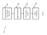
FIG. 5 shows a conceptual flow diagram of a portion of the example of FIG. 1, according to various aspects of the disclosure.
DETAILED DESCRIPTION OF ASPECTS OF THE DISCLOSURE
FIG. 1 shows a conceptual flow diagram of an example according to various aspects of this disclosure. A signal may be received, and candidate symbol sample instants may be obtained from the received signal (not shown); this may be done according to any method. However, symbol timing/clock phase may still not be certain, e.g., because the start time of a packet containing a set of symbols may not be precisely determined by finding the candidate symbol sample instants (and/or for other reasons, such as clock drift, etc.), and this may lead to erroneous reception. The example of FIG. 1 may be used to more precisely determine and correct carrier frequency and track phase variations throughout the reception. According to the example of FIG. 1, a process 10 may include a first pass 11, which may perform initial frequency correction based on the candidate symbol sample instants, a second pass 12, which may perform refined initial frequency correction and phase correction, and a third pass 13, which may perform pilot-aided phase tracking. The corrected symbol sample instants may then be subject to further processing 14, such as, but not limited to, demodulation and decoding. Details of examples of the three- pass correction 11, 12, 13 are described further below.
FIG. 2 shows an example of first pass 11, according to an aspect of this disclosure. The single- pass frequency estimation 110 or 110′ may be performed using any method of non-data-dependent estimation of frequency offset. For example, a “power-of-two” technique may be used for binary-PSK (BPSK), or a “power-of-four” technique may be used for quaternary-PSK (QPSK), and so on. Signaling is not limited to PSK-type signaling, and the frequency estimation technique is not limited to the techniques discussed above. The operation of first pass 11 may depend 109 on a number of candidate symbol samples input. If the number of candidate symbol samples corresponds to a single packet-length's worth of samples, a single pass 110 may be used to perform the initial estimation and to perform frequency correction. However, more generally, there will be more than a single packet-length's worth of samples, and stepping through groups of potential packet-lengths of samples may help ensure that erroneous frequency estimates are not computed, and this may be an iterative process, depending on how many candidate symbol samples are present.
In particular, such a process may begin by extracting from the received candidate symbol samples one packet-length of samples 111, and a non-data-dependent initial frequency offset estimation technique 110′, as discussed above (and which may operate the same as block 110), may be applied to the packet-length of samples. This may be used to frequency-adjust the samples, and the frequency-adjusted samples may be correlated 112 with a known packet synchronization pattern (S) that may be embedded in the symbols. The location of the peak and the SNR at the peak may be stored 113 for later reference. If there are more symbol samples 114, the process may step by a number of symbols equal to the length of the packet synchronization pattern 115, and a next packet length of samples may be selected 111. This process may continue similarly until it is determined 114 that there are no further candidate symbol samples to be examined. At this point, the process may determine the location of the maximum correlation peak 116, which may be selected based on the stored location and SNR information. Frequency correction 110 may then be performed based on a frequency offset estimate corresponding to the set of samples that resulted in the selected maximum correlation peak. The result of first pass 11 may thus be a set of samples that delineates a packet with initial fixed frequency offset corrected, and may thus establish a packet start time.
In some cases, a packet start time may be selected for which there are not sufficient symbol samples to comprise a full packet. In this case, additional symbol instants may be extrapolated, through any acceptable means of specifying symbol timing instants, and their respective symbol values may be added to the end of the packet.
As noted above, and as shown in the example of FIG. 3, a packet 3 may contain an embedded synchronization (“pilot”) pattern, where the synchronization symbols (or “pilot symbols”) of the sync pattern are denoted “P” in FIG. 3. Also, as noted above, a packet synchronization pattern may establish the starting point of a packet, and is represented by “S” in FIG. 3. The synchronization pattern S may be obtained from a pseudorandom sequence. The synchronization symbols P may also be obtained from a pseudorandom sequence, and they may be evenly distributed throughout packet 3. The unmarked symbols in the packet 3 may represent data or other symbols. In general, it may be advantageous to limit the number of synchronization symbols P per packet to only a number necessary for a given channel, in order to maximize information throughput. The number of synchronization symbols may be predetermined and may be based, for example, on experimentation and/or other empirical data (e.g., measurements of channel conditions).
FIG. 4 shows an example of second pass 12, according to an aspect of this disclosure. This may begin by taking the symbol samples selected in first pass 11 and re-performing single-pass frequency estimation and correction 120, which may be done in the same way as or using a different technique from that used in block 110 of FIG. 2. This may serve to further correct the frequency offset of the selected symbol samples. The further-corrected symbol samples may then be correlated with the synch pattern 121, which may serve to confirm the start instant of the packet. An initial carrier phase correction may be derived 122 from the angle of the complex correlation result corresponding to the peak selected in block 116 of FIG. 2. In particular, the initial phase correction may be taken to be the negative of the phase of the peak value output from the correlation 121. This initial phase correction may be applied 122 to all of the symbol samples in the packet.
FIG. 5 shows an example of third pass 13, according to an aspect of this disclosure. The third pass represents the phase tracking/correction operation that may be required as the results of phase variations in the reception due to phase noise, oscillator mismatch, channel variations, etc. The third pass may begin by constructing a phase error phasor sequence 131 based on the corrected symbol samples obtained in the second pass 12. This may be done by multiplying a subset of the corrected symbol samples corresponding to known values, which may correspond to the pilot symbols, e.g., as in FIG. 3, by complex conjugate phasors corresponding to their respective known values.
Next, the resulting error phasors may be integrated/smoothed 132 by applying a moving average or some other low-pass filtering method. The amount of smoothing may be selected based, e.g., on the expected phase fluctuation rate due to phase noise, short-term frequency drift, and/or Doppler rate.
The smoothed error phasors may then be used to derive phase errors 133. This may be done by finding the angle at each smoothed error phasor location and then interpolating to derive phase errors for the symbol samples for which error phasors were not obtained (e.g., information symbols). Phase corrections may then be applied to the symbol samples 134 by using the complex conjugates of the respective phase errors (e.g., by multiplying by unit phasors (complex exponentials) having angles with values that are negatives of the determined angles (i.e., unit phasors that are complex conjugate of unit error phasors; however, the invention is not thus limited, and other techniques for introducing phase shifting may be used).
Following phase tracking/correction, further processing 14, such as, but not limited to, symbol detection, error-control decoding, etc., may be performed.
Various operations described above may be performed by dedicated electronic hardware devices, or alternatively, may be implemented using other hardware, software, or firmware, or combinations thereof, including the possibility of using a processor that may execute software instructions, which may, e.g., be saved on a storage device, and which may cause the operations to be implemented.
Various aspects of the disclosure have been presented above. However, the invention is not intended to be limited to the specific aspects presented above, which have been presented for purposes of illustration. Rather, the invention extends to functional equivalents as would be within the scope of the appended claims. Those skilled in the art, having the benefit of the teachings of this specification, may make numerous modifications without departing from the scope and spirit of the invention in its various aspects.

Claims (33)

What is claimed is:
1. A method of phase tracking in a communication system, the method including:
performing, at a receiving apparatus of the communication system, an initial frequency correction based on received symbol samples, to output first corrected samples, wherein the initial frequency correction comprises performing at least one non-data-dependent frequency estimation and correction on a single packet-length's worth of the received symbol samples, wherein a number of the received symbol samples is greater than one packet length's worth of symbol samples, wherein the initial frequency correction further comprises iteratively stepping through packet-length sets of the received symbol samples to obtain the single packet-length's worth of received symbol samples, and wherein the iteratively stepping through packet-length sets of the received symbol samples comprises:
extracting a symbol block containing one packet-length's worth of received symbol samples;
performing non-data-dependent frequency estimation and correction on the symbol block to obtain frequency-adjusted symbol samples;
correlating the frequency-adjusted symbol samples with a packet sync pattern; and
identifying the packet start sample by the correlation value with maximum magnitude;
performing, at the receiving apparatus, a second frequency correction and initial phase correction on the first corrected samples to output second corrected samples; and
performing, at the receiving apparatus, pilot symbol-aided phase tracking/correction to the second corrected samples.
2. The method of claim 1, wherein the iteratively stepping through packet-length sets of the received symbol samples further comprises:
storing at least one result derived from the correlating;
determining if there are further symbol samples available;
if further symbol samples are available, stepping by a length of one packet sync pattern to extract a further symbol block, performing the non-data-dependent frequency estimation, packet sync pattern correlation, identification of symbol timing instant with maximum correlation magnitude, and storing at least one set of these results; and
if no further symbol samples are available, selecting a symbol block, based on the at least one result, and performing the non-data-dependent frequency estimation and correction on the selected symbol block.
3. The method of claim 2, wherein the at least one result comprises a correlation peak sample instant and a peak signal-to-noise ratio, and wherein selecting a symbol block comprises selecting a symbol block corresponding to a maximum correlation peak.
4. A method of phase tracking in a communication system, the method including:
performing, at a receiving apparatus of the communication system, an initial frequency correction based on received symbol samples, to output first corrected samples;
performing, at the receiving apparatus, a second frequency correction and initial phase correction on the first corrected samples to output second corrected samples; and
performing, at the receiving apparatus, pilot symbol-aided phase tracking/correction to the second corrected samples,
wherein performing the second frequency correction and initial phase correction comprises:
performing non-data-dependent frequency estimation and correction on the first corrected samples, to obtain a block of further corrected samples;
correlating the further corrected samples with a packet sync pattern;
using a peak correlation value to derive a packet timing instant and phase correction; and
applying the phase correction to a packet length of further corrected symbol samples beginning with the selected packet timing instant.
5. The method of claim 4, wherein the initial frequency correction comprises performing at least one non-data-dependent frequency estimation and correction on a single packet-length's worth of the received symbol samples.
6. The method of claim 5, wherein a number of the received symbol samples is greater than one packet length's worth of symbol samples, and wherein the initial frequency correction further comprises iteratively stepping through packet-length sets of the received symbol samples to obtain the single packet-length's worth of received symbol samples.
7. The method of claim 6, wherein the iteratively stepping through packet-length sets of the received symbol samples comprises:
extracting a symbol block containing one packet-length's worth of received symbol samples;
performing non-data-dependent frequency estimation and correction on the symbol block to obtain frequency-adjusted symbol samples;
correlating the frequency-adjusted symbol samples with a packet sync pattern; and
identifying the packet start sample by the correlation value with maximum magnitude.
8. The method of claim 4, wherein the phase correction corresponds to a negative value of a phase of the peak correlation value.
9. A method of phase tracking in a communication system, the method including:
performing, at a receiving apparatus of the communication system, an initial frequency correction based on received symbol samples, to output first corrected samples;
performing, at the receiving apparatus, a second frequency correction and initial phase correction on the first corrected samples to output second corrected samples; and
performing, at the receiving apparatus, pilot symbol-aided phase tracking/correction to the second corrected samples,
wherein the pilot symbol-aided phase tracking/correction comprises:
constructing an error phasor sequence based on the second corrected samples;
applying smoothing to the error phasor sequence to obtain a smoothed error phasor sequence;
deriving one or more phase errors from the smoothed error phasor sequence; and
correcting the second corrected samples based on the one or more phase errors.
10. The method of claim 9, wherein the constructing the error phasor sequence comprises multiplying a subset of the second corrected samples corresponding to known values by complex conjugate phasors corresponding to those known values.
11. The method of claim 10, wherein the known values are pilot symbols.
12. The method of claim 11, wherein the pilot symbols are evenly spaced throughout a packet corresponding to the second corrected samples.
13. The method of claim 11, wherein values of the pilot symbols are selected based on a pseudorandom sequence.
14. The method of claim 9, wherein the applying smoothing comprises applying a low-pass filtering technique, and wherein an amount of smoothing is determined based on at least one item selected from the group consisting of: expected phase fluctuation rate due to phase noise; short-term frequency drift; and Doppler rate.
15. The method of claim 9, wherein the deriving one or more phase errors comprises:
finding an angle corresponding to a respective smoothed error phasor location; and
interpolating between angles to obtain angles corresponding to second corrected samples for which error phasors were not obtained.
16. The method of claim 15, wherein correcting the second corrected samples comprises applying complex phasors with negative values of the respective angles to the corresponding second corrected samples.
17. A storage device containing executable instructions for implementing operations for phase tracking in a communication system, the operations including:
performing an initial frequency correction based on received symbol samples, to output first corrected samples, wherein the initial frequency correction comprises performing at least one non-data-dependent frequency estimation and correction on a single packet-length's worth of the received symbol samples, wherein a number of the received symbol samples is greater than one packet length's worth of symbol samples, wherein the initial frequency correction further comprises iteratively stepping through packet-length sets of the received symbol samples to obtain the single packet-length's worth of received symbol samples, and wherein the iteratively stepping through packet-length sets of the received symbol samples comprises:
extracting a symbol block containing one packet-length's worth of received symbol samples;
performing non-data-dependent frequency estimation and correction on the symbol block to obtain frequency-adjusted symbol samples; and
correlating the frequency-adjusted symbol samples with a packet sync pattern; and
identifying the packet start sample by the correlation value with maximum magnitude;
performing a second frequency correction and initial phase correction on the first corrected samples to output second corrected samples; and
performing pilot symbol-aided phase tracking/correction to the second corrected samples.
18. The storage device of claim 17, wherein the iteratively stepping through packet-length sets of the received symbol samples further comprises:
storing at least one result derived from the correlating;
determining if there are further symbol samples available;
if further symbol samples are available, stepping by a length of one packet sync pattern to extract a further symbol block, performing the non-data-dependent frequency estimation, packet sync pattern correlation, identification of symbol timing instant with maximum correlation magnitude, and storing at least one set of these results; and
if no further symbol samples are available, selecting a symbol block, based on the at least one result, and performing the non-data-dependent frequency estimation and correction on the selected symbol block.
19. The storage device of claim 18, wherein the at least one result comprises a correlation peak sample instant and a peak signal-to-noise ratio, and wherein selecting a symbol block comprises selecting a symbol block corresponding to a maximum correlation peak.
20. A communication apparatus including:
at least one processor; and
the storage device of claim 17, wherein the storage device is communicatively coupled to the at least one processor, and wherein the at least one processor is configured to execute the executable instructions.
21. A storage device containing executable instructions for implementing operations for phase tracking in a communication system, the operations including:
performing an initial frequency correction based on received symbol samples, to output first corrected samples;
performing a second frequency correction and initial phase correction on the first corrected samples to output second corrected samples; and
performing pilot symbol-aided phase tracking/correction to the second corrected samples,
wherein performing the second frequency correction and initial phase correction comprises:
performing non-data-dependent frequency estimation and correction on the first corrected samples, to obtain a block of further corrected samples;
correlating the further corrected samples with a packet sync pattern;
using a peak correlation value to derive a packet timing instant and phase correction; and
applying the phase correction a packet length of further corrected symbol samples beginning with the selected packet timing instant.
22. The storage device of claim 21, wherein the initial frequency correction comprises performing at least one non-data-dependent frequency estimation and correction on a single packet-length's worth of the received symbol samples.
23. The storage device of claim 22, wherein a number of the received symbol samples is greater than one packet length's worth of symbol samples, and wherein the initial frequency correction further comprises iteratively stepping through packet-length sets of the received symbol samples to obtain the single packet-length's worth of received symbol samples.
24. The storage device of claim 23, wherein the iteratively stepping through packet-length sets of the received symbol samples comprises:
extracting a symbol block containing one packet-length's worth of received symbol samples;
performing non-data-dependent frequency estimation and correction on the symbol block to obtain frequency-adjusted symbol samples; and
correlating the frequency-adjusted symbol samples with a packet sync pattern; and
identifying the packet start sample by the correlation value with maximum magnitude.
25. The storage device of claim 21, wherein the phase correction corresponds to a negative value of a phase of the peak correlation value.
26. A storage device containing executable instructions for implementing operations for phase tracking in a communication system, the operations including:
performing an initial frequency correction based on received symbol samples, to output first corrected samples;
performing a second frequency correction and initial phase correction on the first corrected samples to output second corrected samples; and
performing pilot symbol-aided phase tracking/correction to the second corrected samples,
wherein the pilot symbol-aided phase tracking/correction comprises:
constructing an error phasor sequence based on the second corrected samples;
applying smoothing to the error phasor sequence to obtain a smoothed error phasor sequence;
deriving one or more phase errors from the smoothed error phasor sequence; and
correcting the second corrected samples based on the one or more phase errors.
27. The storage device of claim 26, wherein the constructing the error phasor sequence comprises multiplying a subset of the second corrected samples corresponding to known values by complex conjugate phasors corresponding to those known values.
28. The storage device of claim 27, wherein the known values are pilot symbols.
29. The storage device of claim 28, wherein the pilot symbols are evenly spaced throughout a packet corresponding to the second corrected samples.
30. The storage device of claim 28, wherein values of the pilot symbols are selected based on a pseudorandom sequence.
31. The storage device of claim 26, wherein the applying smoothing comprises applying a low-pass filtering technique, and wherein an amount of smoothing is determined based on at least one item selected from the group consisting of: expected phase fluctuation rate due to phase noise; short-term frequency drift; and Doppler rate.
32. The storage device of claim 26, wherein the deriving one or more phase errors comprises:
finding an angle corresponding to a respective smoothed error phasor location; and
interpolating between angles to obtain angles corresponding to second corrected samples for which error phasors were not obtained.
33. The storage device of claim 32, wherein correcting the second corrected samples comprises applying complex phasors with negative values of the respective angles to the corresponding second corrected samples.
US14/922,345 2015-10-26 2015-10-26 Phase tracking Active 2036-02-19 US9692587B2 (en)

Priority Applications (2)

Application Number Priority Date Filing Date Title
US14/922,345 US9692587B2 (en) 2015-10-26 2015-10-26 Phase tracking
PCT/US2016/057937 WO2017074791A1 (en) 2015-10-26 2016-10-20 Phase tracking

Applications Claiming Priority (1)

Application Number Priority Date Filing Date Title
US14/922,345 US9692587B2 (en) 2015-10-26 2015-10-26 Phase tracking

Publications (2)

Publication Number Publication Date
US20170118004A1 US20170118004A1 (en) 2017-04-27
US9692587B2 true US9692587B2 (en) 2017-06-27

Family

ID=58559161

Family Applications (1)

Application Number Title Priority Date Filing Date
US14/922,345 Active 2036-02-19 US9692587B2 (en) 2015-10-26 2015-10-26 Phase tracking

Country Status (2)

Country Link
US (1) US9692587B2 (en)
WO (1) WO2017074791A1 (en)

Cited By (2)

* Cited by examiner, † Cited by third party
Publication number Priority date Publication date Assignee Title
US10560243B2 (en) 2017-01-13 2020-02-11 Qualcomm Incorporated Systems and methods to select or transmitting frequency domain patterns for phase tracking reference signals
US11070335B2 (en) 2017-01-13 2021-07-20 Qualcomm Incorporated Apparatus and method for determining resources for phase tracking reference signal (PT-RS) pilot signals using frequency domain patterns

Families Citing this family (3)

* Cited by examiner, † Cited by third party
Publication number Priority date Publication date Assignee Title
CN109217963B (en) * 2018-08-22 2020-03-24 合肥工业大学 Time alignment method for real-time phasor data of wide area measurement system of power distribution network
CN113630359A (en) * 2021-06-22 2021-11-09 武汉高德红外股份有限公司 Phase tracking method, storage medium and computer
CN115037330A (en) * 2022-05-31 2022-09-09 江苏屹信航天科技有限公司 anti-Doppler transmission method, transmission device and terminal

Citations (9)

* Cited by examiner, † Cited by third party
Publication number Priority date Publication date Assignee Title
US20030058951A1 (en) * 2001-09-24 2003-03-27 John Thomson Efficient pilot tracking method for OFDM receivers
US6567480B1 (en) 1999-08-10 2003-05-20 Lucent Technologies Inc. Method and apparatus for sampling timing adjustment and frequency offset compensation
US7068593B2 (en) * 2001-02-08 2006-06-27 Chung-Ang University Industry Academic Cooperation Foundation Apparatus and method for synchronizing frequency in orthogonal frequency division multiplexing communication system
US20070036065A1 (en) 2005-07-29 2007-02-15 Qualcomm Incorporated Method and apparatus for communicating network identifiers in a communication system
US20070140212A1 (en) 2005-06-17 2007-06-21 Broadcom Corporation Apparatus and method for sampling frequency offset estimation and correction in a wireless communication system
US20080056305A1 (en) 2006-05-22 2008-03-06 Qualcomm Incorporated Phase correction for ofdm and mimo transmissions
US20080089458A1 (en) 2006-04-13 2008-04-17 Qualcomm Incorporated Method and apparatus for clock correction in mimo ofdm
US20110090995A1 (en) 2007-06-21 2011-04-21 Leif Wilhelmsson Simultaneous cell group and cyclic prefix detection method, apparatus and system
US20120027147A1 (en) * 2010-07-30 2012-02-02 Baijayanta Ray Frame and Carrier Synchronization for Unbursted Packetized Transmissions Using Constant-Amplitude Continuous-Phase Frequency-Modulation

Patent Citations (9)

* Cited by examiner, † Cited by third party
Publication number Priority date Publication date Assignee Title
US6567480B1 (en) 1999-08-10 2003-05-20 Lucent Technologies Inc. Method and apparatus for sampling timing adjustment and frequency offset compensation
US7068593B2 (en) * 2001-02-08 2006-06-27 Chung-Ang University Industry Academic Cooperation Foundation Apparatus and method for synchronizing frequency in orthogonal frequency division multiplexing communication system
US20030058951A1 (en) * 2001-09-24 2003-03-27 John Thomson Efficient pilot tracking method for OFDM receivers
US20070140212A1 (en) 2005-06-17 2007-06-21 Broadcom Corporation Apparatus and method for sampling frequency offset estimation and correction in a wireless communication system
US20070036065A1 (en) 2005-07-29 2007-02-15 Qualcomm Incorporated Method and apparatus for communicating network identifiers in a communication system
US20080089458A1 (en) 2006-04-13 2008-04-17 Qualcomm Incorporated Method and apparatus for clock correction in mimo ofdm
US20080056305A1 (en) 2006-05-22 2008-03-06 Qualcomm Incorporated Phase correction for ofdm and mimo transmissions
US20110090995A1 (en) 2007-06-21 2011-04-21 Leif Wilhelmsson Simultaneous cell group and cyclic prefix detection method, apparatus and system
US20120027147A1 (en) * 2010-07-30 2012-02-02 Baijayanta Ray Frame and Carrier Synchronization for Unbursted Packetized Transmissions Using Constant-Amplitude Continuous-Phase Frequency-Modulation

Non-Patent Citations (1)

* Cited by examiner, † Cited by third party
Title
Inr'l Search Report and Written Opinion issued Jan. 19, 2017 in Int'l Application No. PCT/US2016/057937.

Cited By (3)

* Cited by examiner, † Cited by third party
Publication number Priority date Publication date Assignee Title
US10560243B2 (en) 2017-01-13 2020-02-11 Qualcomm Incorporated Systems and methods to select or transmitting frequency domain patterns for phase tracking reference signals
US11070335B2 (en) 2017-01-13 2021-07-20 Qualcomm Incorporated Apparatus and method for determining resources for phase tracking reference signal (PT-RS) pilot signals using frequency domain patterns
US11522656B2 (en) 2017-01-13 2022-12-06 Qualcomm Incorporated Apparatus and method for determining resources for phase tracking reference signal (PT-RS) pilot signals using frequency domain patterns

Also Published As

Publication number Publication date
WO2017074791A1 (en) 2017-05-04
US20170118004A1 (en) 2017-04-27

Similar Documents

Publication Publication Date Title
US9692587B2 (en) Phase tracking
CN111095883B (en) Synchronization in orthogonal time-frequency space signal receivers
JP4763692B2 (en) Signal acquisition in wireless communication systems
EP0186691A1 (en) Technique for acquiring timing and frequency synchronization for modem utilizing known (non-data) symbols as part of their normal transmitted data format
EP1564903A2 (en) Apparatus and method for estimating initial frequency offset in an asynchronous mobile communication system
CN1528059A (en) Downlink synchronisation method for a point-to-mutipoint system wit OFDM modulation
JP2008533874A (en) Frame synchronization in OFDM systems
JP2006014334A (en) Detection apparatus of symbol timing error using channel profile of digital receiver, and detection method of the symbol timing error
US9071327B2 (en) Efficient frequency estimation
US20060153322A1 (en) Method and system for synchronization between transmitter and receiver in a communication system
US7042925B2 (en) Correlation detection improvement by averaging spread spectrum signals
US20220377690A1 (en) Radio receiver synchronization
US7606139B2 (en) Preamble detection using frequency based correlation
CN104641610A (en) Method and apparatus for estimating frequency errors
US9160587B2 (en) Channel tracking in an orthogonal frequency-division multiplexing system
CN108337206B (en) Carrier synchronization method and device for satellite communication
CN101999212A (en) Delay estimation for a timing advance loop
US9838197B2 (en) Memory misalignment correction
JP2008311809A (en) Frame synchronizing device and control method thereof
US20080240296A1 (en) Iterative sequential carrier acquisition
US7012972B1 (en) Minimization of phase equivocation in burst modems
KR20190046120A (en) RECEIVER FRAME DETECTION APPARATUS AND METHOD FOR DVB-S2x SUPER-FRAME SYSTEMS BASED ON BURST TRANSMISSION MODE
US20230362035A1 (en) Methods and devices for estimating a frequency deviation
EP1633057A1 (en) Ultra wide band receiver and coresponding reception method
CN115987327A (en) Two-stage receiving method, system, equipment and medium for non-standard frames

Legal Events

Date Code Title Description
AS Assignment

Owner name: HIGHER GROUND LLC, CALIFORNIA

Free format text: ASSIGNMENT OF ASSIGNORS INTEREST;ASSIGNOR:MCKINLEY, BRUCE L.;REEL/FRAME:036879/0123

Effective date: 20151022

STCF Information on status: patent grant

Free format text: PATENTED CASE

AS Assignment

Owner name: REIS, ROBERT, CALIFORNIA

Free format text: SECURITY INTEREST;ASSIGNOR:HIGHER GROUND LLC;REEL/FRAME:051634/0495

Effective date: 20191201

MAFP Maintenance fee payment

Free format text: PAYMENT OF MAINTENANCE FEE, 4TH YR, SMALL ENTITY (ORIGINAL EVENT CODE: M2551); ENTITY STATUS OF PATENT OWNER: SMALL ENTITY

Year of fee payment: 4