US9698632B2 - Wireless battery charger and charge-receiving device - Google Patents
Wireless battery charger and charge-receiving device Download PDFInfo
- Publication number
- US9698632B2 US9698632B2 US14/709,350 US201514709350A US9698632B2 US 9698632 B2 US9698632 B2 US 9698632B2 US 201514709350 A US201514709350 A US 201514709350A US 9698632 B2 US9698632 B2 US 9698632B2
- Authority
- US
- United States
- Prior art keywords
- coil
- power
- conductive
- coils
- source
- Prior art date
- Legal status (The legal status is an assumption and is not a legal conclusion. Google has not performed a legal analysis and makes no representation as to the accuracy of the status listed.)
- Active, expires
Links
- 238000004891 communication Methods 0.000 claims description 35
- 238000001514 detection method Methods 0.000 claims description 19
- 230000001939 inductive effect Effects 0.000 claims description 16
- 239000004020 conductor Substances 0.000 claims description 11
- 230000000295 complement effect Effects 0.000 claims description 5
- 238000012545 processing Methods 0.000 claims description 5
- 230000005540 biological transmission Effects 0.000 claims description 2
- 230000001681 protective effect Effects 0.000 abstract description 51
- 238000012546 transfer Methods 0.000 description 35
- 230000005672 electromagnetic field Effects 0.000 description 11
- 238000010586 diagram Methods 0.000 description 8
- 230000008878 coupling Effects 0.000 description 7
- 238000010168 coupling process Methods 0.000 description 7
- 238000005859 coupling reaction Methods 0.000 description 7
- 239000000463 material Substances 0.000 description 7
- 239000000126 substance Substances 0.000 description 6
- 238000006243 chemical reaction Methods 0.000 description 5
- 230000003750 conditioning effect Effects 0.000 description 5
- 150000002500 ions Chemical class 0.000 description 5
- 239000011295 pitch Substances 0.000 description 5
- 239000003990 capacitor Substances 0.000 description 4
- 230000007246 mechanism Effects 0.000 description 4
- 238000000034 method Methods 0.000 description 4
- 230000004044 response Effects 0.000 description 4
- 238000003860 storage Methods 0.000 description 4
- XLYOFNOQVPJJNP-UHFFFAOYSA-N water Substances O XLYOFNOQVPJJNP-UHFFFAOYSA-N 0.000 description 4
- 230000008859 change Effects 0.000 description 3
- 239000000446 fuel Substances 0.000 description 3
- 238000009434 installation Methods 0.000 description 3
- 238000012544 monitoring process Methods 0.000 description 3
- 230000010355 oscillation Effects 0.000 description 3
- 230000002441 reversible effect Effects 0.000 description 3
- 230000008901 benefit Effects 0.000 description 2
- 238000010276 construction Methods 0.000 description 2
- 239000000428 dust Substances 0.000 description 2
- 230000004907 flux Effects 0.000 description 2
- 230000006870 function Effects 0.000 description 2
- 230000000670 limiting effect Effects 0.000 description 2
- 238000012986 modification Methods 0.000 description 2
- 230000004048 modification Effects 0.000 description 2
- 230000003287 optical effect Effects 0.000 description 2
- 230000000737 periodic effect Effects 0.000 description 2
- WHXSMMKQMYFTQS-UHFFFAOYSA-N Lithium Chemical compound [Li] WHXSMMKQMYFTQS-UHFFFAOYSA-N 0.000 description 1
- HBBGRARXTFLTSG-UHFFFAOYSA-N Lithium ion Chemical compound [Li+] HBBGRARXTFLTSG-UHFFFAOYSA-N 0.000 description 1
- 208000000260 Warts Diseases 0.000 description 1
- 239000002253 acid Substances 0.000 description 1
- 230000002776 aggregation Effects 0.000 description 1
- 238000004220 aggregation Methods 0.000 description 1
- 238000003491 array Methods 0.000 description 1
- 125000004429 atom Chemical group 0.000 description 1
- 230000033228 biological regulation Effects 0.000 description 1
- OJIJEKBXJYRIBZ-UHFFFAOYSA-N cadmium nickel Chemical compound [Ni].[Cd] OJIJEKBXJYRIBZ-UHFFFAOYSA-N 0.000 description 1
- 238000004364 calculation method Methods 0.000 description 1
- 230000001143 conditioned effect Effects 0.000 description 1
- 230000007423 decrease Effects 0.000 description 1
- 238000011161 development Methods 0.000 description 1
- 230000000694 effects Effects 0.000 description 1
- 230000005684 electric field Effects 0.000 description 1
- 238000004146 energy storage Methods 0.000 description 1
- 238000005516 engineering process Methods 0.000 description 1
- 230000002708 enhancing effect Effects 0.000 description 1
- 210000003811 finger Anatomy 0.000 description 1
- 231100001261 hazardous Toxicity 0.000 description 1
- 238000010438 heat treatment Methods 0.000 description 1
- 229910052739 hydrogen Inorganic materials 0.000 description 1
- 239000001257 hydrogen Substances 0.000 description 1
- 125000004435 hydrogen atom Chemical class [H]* 0.000 description 1
- 230000000977 initiatory effect Effects 0.000 description 1
- 230000002452 interceptive effect Effects 0.000 description 1
- 230000001788 irregular Effects 0.000 description 1
- 229910052744 lithium Inorganic materials 0.000 description 1
- 229910001416 lithium ion Inorganic materials 0.000 description 1
- 238000004519 manufacturing process Methods 0.000 description 1
- 230000013011 mating Effects 0.000 description 1
- 229910052751 metal Inorganic materials 0.000 description 1
- 239000002184 metal Substances 0.000 description 1
- 230000036961 partial effect Effects 0.000 description 1
- 229920000642 polymer Polymers 0.000 description 1
- 230000008569 process Effects 0.000 description 1
- 239000000047 product Substances 0.000 description 1
- 239000000376 reactant Substances 0.000 description 1
- 230000008707 rearrangement Effects 0.000 description 1
- 230000001105 regulatory effect Effects 0.000 description 1
- 210000004935 right thumb Anatomy 0.000 description 1
- 238000006748 scratching Methods 0.000 description 1
- 230000002393 scratching effect Effects 0.000 description 1
- 201000010153 skin papilloma Diseases 0.000 description 1
- 230000000087 stabilizing effect Effects 0.000 description 1
- 239000013589 supplement Substances 0.000 description 1
- 230000001052 transient effect Effects 0.000 description 1
Images


Classifications
-
- H—ELECTRICITY
- H02—GENERATION; CONVERSION OR DISTRIBUTION OF ELECTRIC POWER
- H02J—CIRCUIT ARRANGEMENTS OR SYSTEMS FOR SUPPLYING OR DISTRIBUTING ELECTRIC POWER; SYSTEMS FOR STORING ELECTRIC ENERGY
- H02J50/00—Circuit arrangements or systems for wireless supply or distribution of electric power
- H02J50/60—Circuit arrangements or systems for wireless supply or distribution of electric power responsive to the presence of foreign objects, e.g. detection of living beings
-
- H—ELECTRICITY
- H02—GENERATION; CONVERSION OR DISTRIBUTION OF ELECTRIC POWER
- H02J—CIRCUIT ARRANGEMENTS OR SYSTEMS FOR SUPPLYING OR DISTRIBUTING ELECTRIC POWER; SYSTEMS FOR STORING ELECTRIC ENERGY
- H02J50/00—Circuit arrangements or systems for wireless supply or distribution of electric power
- H02J50/10—Circuit arrangements or systems for wireless supply or distribution of electric power using inductive coupling
- H02J50/12—Circuit arrangements or systems for wireless supply or distribution of electric power using inductive coupling of the resonant type
-
- H—ELECTRICITY
- H02—GENERATION; CONVERSION OR DISTRIBUTION OF ELECTRIC POWER
- H02J—CIRCUIT ARRANGEMENTS OR SYSTEMS FOR SUPPLYING OR DISTRIBUTING ELECTRIC POWER; SYSTEMS FOR STORING ELECTRIC ENERGY
- H02J50/00—Circuit arrangements or systems for wireless supply or distribution of electric power
- H02J50/70—Circuit arrangements or systems for wireless supply or distribution of electric power involving the reduction of electric, magnetic or electromagnetic leakage fields
-
- H—ELECTRICITY
- H02—GENERATION; CONVERSION OR DISTRIBUTION OF ELECTRIC POWER
- H02J—CIRCUIT ARRANGEMENTS OR SYSTEMS FOR SUPPLYING OR DISTRIBUTING ELECTRIC POWER; SYSTEMS FOR STORING ELECTRIC ENERGY
- H02J50/00—Circuit arrangements or systems for wireless supply or distribution of electric power
- H02J50/80—Circuit arrangements or systems for wireless supply or distribution of electric power involving the exchange of data, concerning supply or distribution of electric power, between transmitting devices and receiving devices
-
- H—ELECTRICITY
- H02—GENERATION; CONVERSION OR DISTRIBUTION OF ELECTRIC POWER
- H02J—CIRCUIT ARRANGEMENTS OR SYSTEMS FOR SUPPLYING OR DISTRIBUTING ELECTRIC POWER; SYSTEMS FOR STORING ELECTRIC ENERGY
- H02J50/00—Circuit arrangements or systems for wireless supply or distribution of electric power
- H02J50/90—Circuit arrangements or systems for wireless supply or distribution of electric power involving detection or optimisation of position, e.g. alignment
-
- H—ELECTRICITY
- H02—GENERATION; CONVERSION OR DISTRIBUTION OF ELECTRIC POWER
- H02J—CIRCUIT ARRANGEMENTS OR SYSTEMS FOR SUPPLYING OR DISTRIBUTING ELECTRIC POWER; SYSTEMS FOR STORING ELECTRIC ENERGY
- H02J7/00—Circuit arrangements for charging or depolarising batteries or for supplying loads from batteries
- H02J7/0042—Circuit arrangements for charging or depolarising batteries or for supplying loads from batteries characterised by the mechanical construction
- H02J7/0044—Circuit arrangements for charging or depolarising batteries or for supplying loads from batteries characterised by the mechanical construction specially adapted for holding portable devices containing batteries
-
- H—ELECTRICITY
- H02—GENERATION; CONVERSION OR DISTRIBUTION OF ELECTRIC POWER
- H02J—CIRCUIT ARRANGEMENTS OR SYSTEMS FOR SUPPLYING OR DISTRIBUTING ELECTRIC POWER; SYSTEMS FOR STORING ELECTRIC ENERGY
- H02J7/00—Circuit arrangements for charging or depolarising batteries or for supplying loads from batteries
- H02J7/007—Regulation of charging or discharging current or voltage
-
- H02J7/025—
Definitions
- Portable electronic devices generally require power to operate.
- the electrical power is often supplied at least partly by one or more batteries.
- a user may replace the battery or recharge it.
- Recharging the battery often involves physically attaching the battery or the portable electronic device to a power source, such as a standard electrical outlet, via a power cable.
- An electrical battery typically includes one or more electrochemical cells that convert stored chemical energy into electrical energy.
- a load e.g., an electric circuit such as found in a mobile phone
- elements within the battery are changed due to a chemical reaction within the battery in order to allow ions (atoms having a positive or negative charge) to move between the battery's positive and negative terminals.
- ions atoms having a positive or negative charge
- This movement of ions permits electrical current to flow out of the battery for use by an electrical device.
- a limited amount of ions is available for moving from one terminal to another, and over time the chemical arrangement within the battery changes such that the ions are depleted. In disposable batteries this chemical rearrangement is permanent.
- a battery charger provides the reverse current needed for restoring a battery's charge.
- a typical charger for an electronic device may include a wall plug, a wire attached at one end to the wall plug, and an electrical connector attached to the other end of the wire.
- electrical current from the home electrical outlet is supplied through the wire to the electronic device's circuitry, which may directly or indirectly provide the current to a battery attached to the electronic device.
- Some electronic devices may include circuitry directed to charging or recharging a battery using wireless power transfer. This technology is especially useful in instances where use of wires may be hazardous, impossible, or simply inconvenient.
- mobile phones may incorporate wireless power receiving circuitry that can receive power wirelessly from a wireless charging station. Wireless charging stations are available for conveniently charging phones so equipped, reducing the need to attach a power cable to the phone.
- a time-varying electrical current in an electrical conductor creates a time-varying magnetic field around the electrical conductor.
- the magnetic field is strongest near the electrical conductor, and decreases in strength with distance from the electrical conductor.
- This electromagnetic principle may also operate in reverse. That is, a time-varying magnetic field can induce a time-varying current in an electrical conductor. For example, if an electrically conductive wire passes a permanent magnet, a current is induced in the wire.
- a wireless power source provides a time-varying current to an electrically conductive element, often an antenna formed from a coil of wire. That time-varying current generates a time-varying magnetic field around the coil of the power source.
- a wireless power receiver may also include a conductive element, also typically a coil antenna. If the source coil and receiving coil are sufficiently close together, the time-varying magnetic field around the source coil induces a time-varying electrical current in the receiving coil. This induced electrical current may be used to charge a battery attached to the wireless power receiver.
- inductive wireless power transfer In a variation of inductive wireless power transfer called “magnetic resonance,” the electrical conductors of the source and receiver are tuned to resonate at a predetermined frequency.
- a “resonant circuit” permits greater efficiency of energy transfer in many kinds of systems.
- the reader may be familiar with resonance in an audio setting.
- a particular hummed or sung pitch (frequency) may sound louder (higher amplitude) than other pitches hummed or sung with the same energy.
- the louder pitch is one for which characteristics of the shower stall provide resonance.
- Resonance occurs when a system is able to store and easily transfer energy between two or more different storage modes.
- the shower construction system
- the shower construction is able to store the hummed/sung pitch (audio energy) in the physical construction of the walls and in the volume of air within the shower.
- this energy is easily transferred between vibrations (oscillations) of the walls and vibrations (oscillations) in the volume of air.
- Changes in the characteristics (e.g., dimensions or materials) of the shower could change the pitch (frequency) at which the resonance occurs, or could prevent resonance altogether. Because of resonance, the resonant frequency reflected from the shower walls fades much more slowly than non-resonant frequencies
- a wireless power transfer system can achieve higher power-transfer efficiency compared to non-resonant inductive charging. This increase in efficiency can permit power transfer over a greater distance compared with normal (non-resonant) inductive charging, and/or may permit faster charging due to comparatively higher amount of power received by a receiving device. The greater distance and efficiency may also permit less precise alignment of source and receiving antennas than is necessary in non-resonant inductive charging systems.
- a changing electric current is provided to an electrically conductive source coil.
- the changing electric current generates a changing magnetic field around the coil, and the strength of the magnetic field corresponds to the strength of the changing electric current in accord with electromagnetic principles.
- the magnetic field weakens with distance from the source coil.
- a receiving coil within range reacts to the generated magnetic field, inducing a changing electromotive force (EMF) in the receiving coil.
- EMF electromotive force
- Each of the three main competing wireless power systems includes a data communication channel in addition to the power transfer channel described above.
- the QI and PMA systems include single-direction communication—from power receiving device to power transmitter—typically using data modulation on the power carrier frequency.
- a receiving device may employ “backscatter modulation” in which the amount of power drawn by a perceived load of the receiving device is modulated according to a communication protocol.
- the receiving coil's change in power draw affects the magnetic coupling between the source coil and receiving coil, and is thus detectable at the power transmitting device.
- A4WP instead provides two-way wireless data communication between power transmitter and power receive over a separate communications channel (e.g., using BLUETOOTH low energy, a.k.a. BLUETOOTH SMART).
- Inductive wireless charging uses low frequency near-field electromagnetic coupling between a primary (or source) antenna and a secondary (or receiving) antenna. Due to limitations of low-frequency, near-field inductive coupling, the distance between the primary and secondary antennas is generally on the order of a few millimeters, and a substantially precise alignment is required between the source and receiving antennas. Magnetic resonance power transfer uses a higher frequency which permits a coil distance of at least four times the diameter of the coil, and need not be so precise in alignment. The power transfer efficiency is substantially lower, however, particularly as distance increases.
- Cupholder based wireless charging devices described in the art include either a planar surface on which a receiving device is placed, or a single charging coil permanently (or semi-permanently) oriented within the cupholder to be parallel with a chief surface of a typical device to be charged. (See U.S. Pat. No. 8,541,974; U.S. Pat. No. 8,310,200.) However, such wireless chargers do not permit multiple orientations of a chargeable device. Wireless chargers disclosed herein provide a solution to this problem.
- a protective enclosure for a portable electronic device may serve to protect the electronic device from such damage while also providing additional electronic features.
- a protective enclosure for a portable electronic device may provide electronic features not available in the device itself, such wireless power features by which the protective enclosure can capture energy from a time-varying magnetic field generated from one or more wireless charging coils in a wireless charger.
- the protective enclosure may include a battery.
- a mobile device When its user is in a vehicle, a mobile device may commonly be placed in the vehicle's cupholder. Typically, different users may place the mobile device in the cupholder in any of an infinite number of orientations. For example, a vehicle driver may place a mobile device in the cupholder in an orientation convenient for readability or easy access from the driver seat, or may casually dump the mobile device in the cupholder without regard to its orientation. A passenger may wish to use the same cupholder to charge a second device, in addition to the driver's device. If the passenger is the sole user of the cupholder for charging purposes, the device orientation may be different from the orientation the driver would use.
- prior cupholder based wireless chargers may fail to address a plurality of portable device orientations
- the present disclosure presents a wireless charger for a portable electronic device in which a user's portable electronic device could, automatically, be wirelessly while in a variety of orientations, thus prolonging the use time of the device with minimum inconvenience to the device user.
- a wireless charging apparatus for charging a battery of a portable electronic device may include a plurality of electrically conductive coils and electronic circuitry.
- the conductive coils may each form a portion of a perimeter around a receiving area.
- the receiving area is arranged to receive the portable electronic device, and each conductive coil may have a central axis around which the respective conductive coil is formed.
- the central axis of each conductive coil may be directed inward from the perimeter such that each coil faces substantially inward.
- Each conductive coil in the plurality of conductive coils may include at least one loop of electrically conductive material, and the ends of each conductive coil may constitute electrical leads.
- the electronic circuitry includes an electric power receiving circuit and a coil controller.
- the electric power receiving circuit may be arranged or programmed to receive electrical power and to provide at least a portion of the electrical power to the coil controller.
- the coil controller may be electrically connected to the electric power receiving circuit and to the electrical leads of the conductive coils.
- the controller may include components arranged or programmed to selectively provide a changing electric current to at least one of the conductive coils, where the changing electric current induces a magnetic field around the respective conductive coil that is selected for receiving the changing electrical current.
- a mounting apparatus for a portable electronic device may include a gripping device and electronic circuitry.
- the gripping device may include at least a first side-engaging portion and a second side engaging portion.
- the first and second side-engaging portions may be disposed generally opposite each other and may be formed to engage sides of the portable electronic device.
- Each side-engaging portion may respectively include at least one electrically conductive coil, where each electrically conductive coil may have at least one electrical lead for electrically connecting the coil.
- the electronic circuitry may include an electric power receiving circuit and a coil controller.
- the electric power receiving circuit may be arranged or programmed to receive electrical power and to provide at least a portion of the electrical power to the coil controller.
- the coil controller may be electrically connected to the electric power receiving circuit and to the electrical leads of the electrically conductive coils.
- the controller may be arranged or programmed to provide a changing electric current to at least each of the electrically conductive coils in the gripping device, where the changing electric current may induce a magnetic field around the electrical
- a protective enclosure for a portable electronic device may include a hard shell.
- the hard shell may include a substantially planar portion that may receive a back of the portable electronic device.
- the substantially planar portion may house power-receiving circuitry.
- the hard shell may also include side walls extending from each of two opposing side edges of the substantially planar portion.
- the side walls each may include a respective power-receipt coil.
- the power-receipt coil may be arranged for corresponding to one or more charging coils provided in a charging apparatus, and each power-receipt coil may include leads connected to the power-receiving circuitry.
- the protective case may also include an internal connector connected at a bottom wall of the hard shell, and the internal connector may be disposed to interface with an electrical connector of the portable electronic device.
- an electric current may be induced in the power-receipt coils.
- the power-receiving circuitry may process the electric current for use by at least one of the protective enclosure and the portable electronic device.
- FIG. 1 shows a top perspective view of a disclosed wireless charger applied in a vehicle cupholder
- FIGS. 2A-2C illustrate embodiments of wireless charger including source antennas disposed around charging areas of different perimeter geometries
- FIG. 3 is a top perspective view of a cupholder based wireless charger that implements four coil-type source antennas
- FIG. 4 is a block diagram illustrating elements of electronic circuitry in a wireless charger
- FIG. 5 is a block diagram illustrating an embodiment of electronic circuitry for a wireless charger
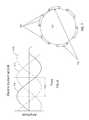
- FIG. 6 is a graph showing three phases of electric current in a disclosed three-phase wireless charger system
- FIG. 7 is a top cross-sectional view of a wireless charger having six source antennas dispersed around a circular charging area;
- FIG. 8A is a top-front perspective view of a device to be charged
- FIG. 8B is a side cutaway view of a device to be charged, where a portion of the outermost shell or housing of the device to be charged is cut away to expose a side-disposed receiving antenna and receiving antenna leads;
- FIG. 8C is a cutaway, top-rear perspective view of a protective case having disclosed wireless charging circuitry
- FIG. 9 shows a block diagram of power receiving circuitry for a device to be charged by wireless power transfer
- FIGS. 10A and 10B illustrate a top view of a cupholder having a wireless charger together with a device to be charged disposed therein;
- FIG. 11 illustrates a device to be charged that includes a rechargeable battery disposed within walls of the device to be charged
- FIG. 12 shows the device to be charged as in FIG. 11 , with the addition of a rear-disposed receiving antenna
- FIG. 13 is a partial cutaway view of part of a mounting apparatus for a portable electronic device or protective enclosure and having wireless power receiving antennas;
- FIG. 14 shows an alternative embodiment of a wireless charger in which a cup-shaped structure is surrounded by one or more loops of electrically conductive material and an electromagnetically insulated material.
- a vehicle may incorporate a wireless charging station into an area of the vehicle for convenience of a driver or passenger in charging her mobile phone or other wirelessly chargeable device.
- a vehicle-based phone charger incorporating wireless power transfer may require less time and attention to use than a wired charging device, and may thus reduce the driver's distraction and increase driver's safety.
- FIG. 1 shows a top perspective view of a disclosed wireless charger 100 applied in a cupholder 110 , for example a cupholder in a vehicle.
- the wireless charger may include several source antennas 120 , attached by leads 122 to electronic circuitry 130 .
- the electronic circuitry 130 may include one or more antenna controllers 132 and a power receiving circuit 134 that may receive power from an external power source, each of which is described in detail below.
- FIG. 1 is not drawn to scale, and relative positions of components may vary.
- the electronic circuitry 130 may be disposed under the cupholder, around the cupholder as with a curved circuit board, or may be provided in a remote location connected via one or more cables.
- the source antennas 120 include coils of electrically conductive wire.
- each source antenna 120 may alternatively be formed of a single conductive strip, such as microstrip, or wire, may be formed in a straight line, in a loop, or as a coil as shown in FIG. 1 .
- one or more of the source antennas 129 may be formed as an inductively- and/or capacitively-coupled group of conductive strips or wires disposed in electrically significant patterns (not shown).
- Each source antenna 120 may be formed as a discrete antenna as illustrated in FIG. 1 , or may be printed on a rigid or flexible circuit board having one or more layers.
- FIGS. 2A-2C illustrate wireless chargers having different shapes.
- the diagrams of FIGS. 2A-2C in general present variations of a disclosed wireless charger include two or more source antennas 220 disposed around a charging area having: a circular cross-section 223 as shown in FIG. 2A , an oval cross-section 224 as shown in FIG. 2B , or even a polygonal cross-section such as the rectangular cross-section 225 of FIG. 2C .
- Elements in FIGS. 2A-2C are numbered similarly to corresponding elements in FIG. 1 .
- a charging area 223 , 224 , 225 may be a two- or three-dimensional space within a perimeter 226 .
- Energy may be transferred wirelessly from the wireless charger to a wireless-power receiving device placed within the charging region, as discussed in more detail below.
- a container such as a cupholder, having a charging area may have an irregular perimeter, for instance including a notch for a coffee cup handle.
- the charging area may include or exclude areas of the corresponding container for which a pertinent portion of an electronic device would not likely enter.
- the source antennas 220 in some instances may roughly form the perimeter 226 of the charging area into which a wirelessly chargeable device may be placed for charging.
- the antennas 220 may be formed in a non-planar shape, e.g., conforming to a curved, spherical, or other surface.
- FIG. 3 is a top perspective view of a wireless charger that, for ease of illustration, implements only four, coil-type source antennas 320 of the same type as source antennas 120 , 220 in earlier figures, within a cylindrical shape 310 , such as the cupholder 110 of FIG. 1 .
- the source antennas 320 are oriented to substantially face a central axis 340 of the cupholder 310 and may thus direct respective magnetic fields at least partially toward a charging area within the cupholder 310 .
- the source antennas 320 forming the perimeter may be substantially identical to each other, or may include different antenna forms (not shown). For example, coil antennas may be mixed with non-coil conductive strips, for example, to address spacing issues or to provide additional field coverage.
- a coil of a size for high efficiency power transfer may be too large to be accommodated in a first space.
- a conductive strip such as microstrip, may instead be used in such space.
- another portion of the wireless charger may accommodate a coil-shaped source antenna, that portion may include a coil-shaped source antenna in addition to, or instead of the conductive strip source antenna in the first space.
- a gripping portion may be insufficiently wide to accommodate a coil antenna, or the coil may not provide adequate coverage at some portions. Accordingly, a strip may be used in place of, or to supplement, a coil-shaped source antenna.
- the antennas may be placed in spaced configurations (as in FIG. 3 ) or overlapping configurations (as in FIG. 1 ) and may form a two- or three-dimensional array.
- the ring of source antennas 120 shown in FIG. 1 could be duplicated above and/or below the source antennas 120 .
- the source antennas may be uniformly (or non-uniformly) angled upward such that one or more of the source antennas is parallel with a back surface of an electronic device when placed in a leaning orientation within the charging area.
- a source antenna intended to communicate power to a receiving antenna in the back of the phone may thus provide better alignment when angled similarly to the phone's power receiving antenna.
- the charging area perimeter formed by the coil-type source antennas 320 is circular.
- the illustrated source antennas have antenna axes 322 , 324 that intersect at a point 342 within the perimeter.
- antenna axes may be offset above or below a plane 350 defined by centers of the conductive coils.
- axes may in some implementations only approximately intersect, as the axes may be slightly offset.
- each pair may include a first antenna/coil disposed across the perimeter formed by the antennas/coils 320 , approximately opposite a second coil of the pair of conductive coils. The orientation of a device to be charged may align with one pair of antennas/coils better than another pair.
- Circuitry may be employed to determine and select a pair of source antennas/coils 320 that best aligns with receiver coils of a portable electronic device (such as a phone case) placed within the charging area perimeter, and provide a changing electric current only to the selected pair of source antennas/coils 320 .
- FIG. 4 is a block diagram illustrating electronic circuitry 400 of a wireless charger, corresponding to the electronic circuitry 130 in FIG. 1 .
- the electronic circuitry includes an antenna controller 410 and a power receiving circuit 470 .
- the antenna controller 410 may include at least one antenna driving circuit 420 to which a respective one or more source antennas, such as source antennas 120 , 220 , 320 may be connected via leads 430 from the source antennas.
- Antenna driver 420 may include a signal generator 422 , such as an oscillator, that provides a current waveform.
- the waveform may be substantially sinusoidal, or may be a more complex waveform.
- the antenna driver 420 may further include a current amplifier 424 that amplifies the current waveform generated by the signal generator 422 .
- the waveform produced by the antenna driver 420 may be predetermined, and the antenna driver 420 may in some embodiments produce the predetermined electric current waveform from a hard-configured arrangement of components or from a table of stored parameters for programmably configuring waveform-producing circuitry.
- the current amplifier 424 is adjustable depending on a feedback received from a device to be charged, such as a mobile phone, protective case, or other mobile device having wireless power-receiving circuitry.
- the antenna driver 420 may further include phase delay circuitry or mechanisms 426 in order to provide a phase-delayed iteration of the current waveform generated by the signal generator 422 . For example, use of multiple phase delay mechanisms or circuits may result in supply of 3-phase current to selected source antennas.
- a multi-phase inverter may receive a single direct current (DC) voltage and provide a multi-phase changing current, such as 3-phase current, for application to source antennas.
- Antenna controller circuit 410 may include a single antenna driver 420 that connects to all of the source antennas. Alternatively, groups of two or more source antennas may be connected to respective antenna driving circuits 420 , or each source antenna may be connected to its own driving circuit.
- FIG. 5 illustrates a block-diagram example of an antenna control circuit, for example, that includes multiple antenna driving circuits 420 , electrical leads 430 , processor 415 , memory 417 , and data communication receiver or transceiver 419 .
- the electrical leads 430 from pairs of antennas (not illustrated) are connected to respective antenna drivers 420 .
- the processor 415 may manage and coordinate the functions of the antenna drivers 420 and may be associated with memory 417 that holds instructions to be executed by the processor 415 .
- the processor 415 may include one or more appropriately configured microprocessor or microcontroller circuits, digital processors, programmable logic arrays, programmable logic devices, state machines, discrete components or combinations thereof.
- the memory 417 may include one or more read only memory (ROM) and/or random access (RAM) memory, magnetic media such as a hard-disk drive, optical media and optical reader, flash memory, solid-state memory, and the like.
- the data communication receiver/transceiver 419 may in some embodiments receive and decode communications received from a device to be charged. In some implementations the data communication receiver/transceiver 419 may additionally provide communication to the device to be received as described in more detail below.
- the multiple source antennas may be energized simultaneously with the same electrical current waveform at the same phase, or may be energized simultaneously by different phases of electrical current.
- FIG. 6 illustrates three simultaneous phases 610 , 612 , 614 of a sine-wave electrical current, with each phase offset from the others by 120 degrees.
- a time-varying electric current for generating a magnetic field need not be limited to a sinusoidal wave form, and need not be centered about a zero voltage as illustrated.
- the relative strength of a magnetic field generated at each of three groups of source antennas at any given time t in a wireless charging array may correspond proportionally to the electric current that energizes the corresponding source antenna(s) of the group, where each source antenna is energized according to a time-varying current waveform, such as a sinusoidal waveform.
- a time-varying current waveform such as a sinusoidal waveform.
- FIG. 7 illustrates a top cross-sectional view of a wireless charger having six source antennas 720 dispersed around a circular charging area 723 .
- the X and • notation for each of the energized source antennas 720 denotes a direction of current flow.
- each source antenna 720 of an opposing pair of source antennas 710 may receive the same phase of a current waveform, such as the sinusoidal waveform 610 of FIG. 6 .
- the remaining opposing pairs of source antennas may respectively receive the sinusoidal waveforms 612 , 614 of FIG. 6 .
- different phases of the electrical current waveform may be simultaneously provided to permit all of the source antennas to be energized at the same time. This may reduce a surge of electrical current needed at any given moment, compared with providing the same phase to all source antennas at the same time. That is, if all source antennas received peak current at the same time, the circuitry needed to drive the source antennas would need to be selected for a higher total current than when only one source antenna, or sub-group of source antennas receives peak current at a given time.
- One advantage of this scenario may be the potential to provide wireless power to more than one device to be charged at a time without undue surges in current.
- one device to be charged e.g., a first mobile phone
- a wireless charger may be placed in the charging area of a wireless charger at a particular orientation that aligns receiving antennas, of the device to be charged, with a first set of source antennas.
- Another device to be charged e.g., a second mobile phone
- Each of the mobile phones may receive power wirelessly from different sets of source coils with electric current waveforms having peaks that are offset from each other.
- the provision of different phases of the electric current waveform to different sets of source antennas may be performed only to detect which of the source antennas or sets of source antennas most closely align with receiving coil(s) of a device to be charged. If all source antennas received the same current waveform at the same time, the magnetic field generated from neighboring source antennas may impede determination of which source antenna(s) best align with the receiving antenna(s) due to combining of magnetic fields.
- an antenna controller such as antenna control 410 may provide current to individual source antennas or sets of source antennas in a detection sequence.
- a data communication receiver or transceiver of the antenna controller circuitry monitoring for a responsive communication at each source antenna.
- responsive communication may include a value representing received power level.
- a highest received power levels among power levels received in correspondence to power supplied from each source antenna may indicate one or more most appropriate source antennas (generally the source antenna(s) most proximate to receiving antenna(s) of a device to be charged) for supplying power.
- the most appropriate antenna(s) may continue to be provided with an electric current waveform while the less appropriate source antennas (those for which a communication reply is not received or for which the communication reply indicates lower power received) may receive no electric current waveform or only an occasional electric current waveform provided for the purpose of ensuring that the most appropriate or most closely aligned source antenna(s) have not changed, e.g., due to shifting of the device to be charged.
- the less appropriate source antennas hose for which a communication reply is not received or for which the communication reply indicates lower power received
- the less appropriate source antennas may receive no electric current waveform or only an occasional electric current waveform provided for the purpose of ensuring that the most appropriate or most closely aligned source antenna(s) have not changed, e.g., due to shifting of the device to be charged.
- Those of ordinary skill in the art will acknowledge that more or fewer current waveform phases may be employed, and that even with a three-phase system the phases may be offset by other than 120 degrees.
- magnetic fields from two or more source antennas may be strategically combined to target a specific portion of the charging area.
- a source antenna controller may energize respective source antennas using multiple electrical current waveforms.
- the waveforms may be made complementary to each other for constructive aggregation, thus providing a stronger oscillating magnetic field at a target charging region among several possible or predetermined charging regions within the charging perimeter.
- several magnetic fields may be additively combined to provide a highest magnetic field at a particular area. For example, when only one source antenna is energized with a time-varying electric current, the magnetic field may be strongest in a particular area near the source antenna. In a coil-shaped antenna, the magnetic field is typically strongest along an axis passing through the center of the coil.
- a device to be charged such as a mobile phone, may be placed within a charging area according to any of several orientations corresponding to a charging region and still be able to effectively engage the source antennas.
- an electromagnetic field may induce an electrical current in certain conductive objects in addition to receiving coils. Inherent resistance in some of these objects can cause them to heat up in response to the induced current. For example, as little as 500 mW of power can result in a coin heating to 80+ degrees Celsius—hot enough to melt plastic or burn skin. Thus, for safety and efficiency in disclosed embodiments, electric current may not be provided to the source antennas at all times.
- the wireless charger may include a foreign object detection circuit that can turn off the charger (cease providing current to the source antenna(s)) when certain types of foreign object are detected.
- Established mechanisms for such detection include a loss monitoring scheme, where the power received at a device to be charged (e.g., receiving antenna(s)) is compared with power provided by source antennas, taking into consideration losses inherent in the system; if the losses are greater than expected, the charger may not provide current to the source antenna corresponding to the unexpected power loss.
- a device to be charged e.g., receiving antenna(s)
- Embodiments of a wireless charger according to the present disclosure may alternatively include a per-source antenna control or a whole system control.
- the per-source control may detect losses for each source antenna individually and thence control the current provided to each source antenna according to whether or not unexpected power losses correspond to that source antenna.
- an unexpected power loss between any source antenna and a receiving antenna may result in the entire wireless charger being at least temporarily disabled.
- loss monitoring may be implemented using a loss detection circuitry constituting a detection unit.
- the detection unit may include data communication circuitry and a processing circuit, such as a comparator or processor, that may calculate losses based on information received from a device to be charged that has a receiving antenna.
- a device to be charged may include communications circuitry for communicating with an antenna controller described above and/or detection unit of the wireless charger via one or more of several communication means. Some disclosed embodiments may employ modulation of the coupled electromagnetic field used for power transfer. For example, circuitry associated with a receiving antenna may selectively modulate a load, thus affecting the amplitude of the induced magnetic field. This modulation may be decoded at the antenna controller of the power source as feedback indicating the power levels needed, power levels received, etc.
- data communication between the source and receiving devices may include other wireless communication circuitry and protocols, including but not limited to WI-FI, BLUETOOTH, BLUETOOTH SMART (also called BLUETOOTH low energy), ZIGBEE, or the like.
- the data received by the detection unit may include any of at least: the amount of power received at the receiving antenna of the device to be charged, a difference between power received and power expected, and/or expected losses at the receiving antenna.
- the processing unit or processor may use the received information to calculate losses and compare with expected losses. Alternatively, the processing unit or processor of the detection unit may simply compare the received information with expected values. If the results of the calculation and/or comparison indicate the presence of a foreign object in addition to the device to be charged, the detection unit may prevent supplying current to the source coil that corresponds to the power losses indicating a foreign object or damage to the coil or related circuitry. In some implementations, the detection unit may use predetermined threshold ranges for values of expected losses and/or power received at the device to be charged.
- a first threshold range may include maximum and minimum values between which the actual loss or received amount of power indicate the presence of a foreign object
- a second threshold range may include maximum and minimum values between which the actual power loss or received amount of power are expected.
- the threshold ranges may be predetermined and included in a look-up table or may be regularly calculated anew, e.g., at device power up.
- the detector may also include circuitry such as a processor or discrete components programmed or arranged to determine which source antenna or antennas best correspond to receiving antennas of a device to be charged. The determination of best-corresponding source antenna(s) may be performed periodically. The determination of best-corresponding source antenna(s) may include causing the source antenna controller to provide an amount of current to each source antenna, or selected subsets of the source antennas, in a predetermined sequence and receiving a communication from the device to be charged in response to each electrical current induced at the device to be charged, in which communication the device to be charged may report the strength of the induced current.
- circuitry such as a processor or discrete components programmed or arranged to determine which source antenna or antennas best correspond to receiving antennas of a device to be charged. The determination of best-corresponding source antenna(s) may be performed periodically. The determination of best-corresponding source antenna(s) may include causing the source antenna controller to provide an amount of current to each source antenna, or selected subsets of the source antennas, in a predetermined sequence and
- the source antenna(s) corresponding to the best (e.g., highest) induced current may be controlled to provide wireless charging to the device to be charged, while remaining source antenna(s) may be disabled until another of the periodic determinations of best-corresponding source antenna(s).
- the wireless charger is able to automatically configure or reconfigure itself to increase the amount of charging current delivered to a device placed in the charger even though the device may be oriented differently each time it is placed in the charger.
- the next determination of best-corresponding source antenna(s) may receive no communication in response to electromagnetic fields generated at any source antenna, and the source antenna controller may thus rest dormant until the next periodic determination of best-corresponding source antenna(s).
- a power receiving circuit such as power receiving circuit 134 in FIG. 1
- the presently disclosed wireless charger features may be applied in a variety of portable electronic device holders that may or may not naturally orient the portable electronic device to align source and receiving antennas.
- a cupholder-shaped charger is described above, the wireless charger features are not limited to a cupholder or to a vehicle.
- cupholder or other non-orienting holder format for wireless charging may also be useful in certain non-vehicle settings.
- a fully or partially cup-shaped holder may be useful in an office setting as a convenient phone holder, where a user can simply place the phone in the holder without thought to orientation.
- the exemplary wireless charger embodiments disclosed herein may alternatively receive power from an alternating current (AC) home circuit using an appropriate power converter that may be part of an external circuit (e.g., a “wall-wart”, or transformer) or using internal circuitry of the wireless charger appropriate for conversion of AC power.
- the power receiving circuit of the wireless charger may perform one or more of power conversion from a higher or lower DC voltage to a voltage usable by circuitry of the wireless charger.
- a DC converter may receive 6 volt, 12 volt, or 24 volt DC power from a vehicle battery and convert it to 5 volt DC power or another lower voltage for use by other circuitry of the wireless charger.
- the power receiving circuitry may further condition the input power by regulating, rectifying, stabilizing, and/or otherwise preparing the input power for best use by the wireless charger circuitry.
- Source antennas of a wireless charger may produce electromagnetic fields that could in certain situations affect surrounding circuits, including vehicle electronics, pacemakers, etc.
- a housing of the wireless charger such as a vehicle cupholder, may include electromagnetic shielding placed to limit the area affected by the electromagnetic fields.
- a cupholder implementing a disclosed wireless charger may include shielding around the sides and on the bottom of the cupholder.
- the cupholder may also include selectively removable electromagnetic shielding over its top.
- the source antennas may be placed internally to, externally to, or between walls of a device holder such as the cupholder shape described above. Electromagnetic shielding may be implemented to eliminate or reduce the external effects of electromagnetic fields generated by the wireless charger.
- the wireless charger may be provided as an after-market product available for user installation in a vehicle cupholder.
- a user may obtain a wireless charger, for example in a wireless charger kit, and install an array of source coils and accompanying circuitry of the wireless charger in an existing cupholder.
- a power cord may be provided in the kit, or obtained separately, permitting connection between the power receiving circuitry and an external power source.
- a cable may be provided having a standard connector, such as a micro USB connector, at one end, and a 12-volt accessory plug at the other end.
- a wireless charger installation may include accessing a back/bottom side of an existing cupholder or other cavity during vehicle assembly or later, after disassembly of a console or other region having a cavity suitable for wireless charging.
- the wireless charger may be installed around an interior portion of the cupholder, thus hiding the coil array from sight.
- a connection to vehicle power may be wired directly to a fuse box or other vehicle power access point.
- Embodiments of the wireless charger for use in a vehicle may include communication circuitry for communicating with a vehicle's information systems in order to provide information regarding charging and the like.
- the wireless charger may include fuel gauge circuitry configured to calculate a charge level and time to charge for a battery located in the device to be charged.
- the communication circuitry for communicating with the vehicle's information systems may provide the charge level or charging time information to the vehicle's information systems for convenient display to the driver via an in-dash indicator, information screen or the like.
- various indicators such as information screens, LEDs, or the like may notify the corresponding seat occupant of the charging information.
- a conventional device to be charged may include only a single wireless power receiving antenna disposed at the rear plane of the device. This arrangement permits proximity to the source antenna of a planar charging device (e.g., a charging mat) when the device is laid down directly on the surface of the planar charging device. However, when such a device is placed within a charging area of the wireless charger disclosed herein the planar receiving antenna may be insufficiently proximate to a source antenna.
- a cupholder-based charger described above includes a ring of conductive coils disposed around a cylindrical wall of a cupholder. The cylindrical wall may have a round or oval cross section and may have a uniform or varying thickness.
- the cylinder wall may be made thinner where it corresponds to a source antenna and comparatively thicker elsewhere, e.g., for structural strength.
- the cylinder wall may have ribs or other structural features to increase its structural integrity, and may include, at an inside surface of the cylinder wall, one or more protrusions for engaging a cup and/or for securely holding or orienting a device to be charged.
- some or all of the source antennas may be formed or embedded within the cylinder wall.
- the mobile phone When a conventional device to be charged is placed in the cupholder, the mobile phone may lean against the top rim of the cupholder at an angle such that the conventional device's single receiving coil is angled away from a source coil of the wireless charger, thereby preventing electromagnetic coupling or at least reducing the strength of the coupling and related charging efficiency. That is, an inductive coil conventionally placed at the back of the phone may, when used with the above-disclosed three-dimensional wireless charger, be sufficiently distant from a source coil that wireless charging would be inefficient and slow, if even possible. There are at least two ways to address this problem.
- the source antennas themselves may be angled to better accommodate a leaning electronic device.
- a cupholder-based wireless charger may be formed having a beveled surface corresponding to source antennas such that a conventional device to be charged would contact or more-proximately align with a source antenna.
- the device to be charged may include receiving antennas disposed at the sides of the device. Such placement of plural receiving antennas may permit much closer proximity between source and receiving antennas, despite variety of device size, as shown in FIGS. 8A to 8C and 9 .
- FIG. 8A illustrates a protective case 800 having a rigid external shell 810 and various electronic circuitry related at least to the wireless power transfer. It will be recognized that elements of FIGS. 8A-8C may also apply to embodiments of a mobile electronic device itself, such as a mobile phone.
- the rigid shell 810 includes at least side walls 812 , a bottom wall 814 and a substantially planar back portion 816 from which the side walls 812 and bottom wall 814 extend.
- the back portion 816 of the rigid shell 810 may receive the back of a mobile phone or other portable electronic device. It will be appreciated that the back portion of the rigid shell may be formed to accommodate phone geometries that are not substantially planar, such as curved back.
- the rigid shell may further include a top wall that extends from the back portion.
- Embodiments may further include a face portion that joins the side, bottom, and/or top walls and defines an aperture permitting access to an interactive control of an encased mobile phone or other portable electronic device.
- a face portion that joins the side, bottom, and/or top walls and defines an aperture permitting access to an interactive control of an encased mobile phone or other portable electronic device.
- some or all of the side, bottom or top walls may extend from the face portion rather than from the back portion, or that each of the back and face portions includes a portion of some or all of the walls.
- the side and bottom walls 812 , 814 may extend from the substantially planar back portion 816 in a first shell portion, whereas the top wall and front portion may constitute a second shell portion.
- Other combinations will be acknowledged by those having ordinary skill.
- FIG. 8B shows a side cutaway view of a protective case 800 , where a portion of the outermost shell 810 of the protective case has been cut away to expose a side-disposed receiving antenna 830 and receiving antenna leads 835 .
- a second receiving antenna (not shown in this view) may be similarly disposed on the opposite side of the protective case 800 .
- the receiving antenna leads 835 connect each receiving antenna to power receiving circuitry 840 (described in detail below with respect to FIG. 9 ).
- the power receiving circuitry 840 is illustrated here as being at a back, bottom portion within the protective case, the charging circuitry could be located in a side, top, or anywhere along the back within enclosed walls of the protective case 800 .
- Power receiving circuitry 840 may be placed to avoid interference with communications of an enclosed electronic device, to minimize the size of the protective case 800 , and/or to minimize length of the receiving antenna leads 835 .
- FIG. 8C shows a cutaway rear perspective view of the protective enclosure 800 where a portion of the outermost shell 810 is removed to expose power receiving circuitry 840 .
- the receiving antenna may include other forms of antenna, such as a strip (or microstrip) antenna at each side edge.
- FIG. 8C further illustrates that a protective case according to the disclosure may include a battery 850 , such as a rechargeable battery.
- the power receiving circuitry 840 may receive a time-varying current induced by a magnetic field in at least one of the receiving antennas 830 and convert the time-varying current to a direct current for use by an electronic device encased by the protective enclosure and/or for charging the battery 850 via a battery charging circuit (not shown).
- battery herein may be shorthand for “electrical power storage device”, and may include any of a variety of electrical power storage means.
- battery 850 may include one or more rechargeable cells having any of various chemistries, such as lithium-ion, lithium polymer, lead-acid, nickel cadmium, and the like.
- the battery may alternatively or additionally include a capacitive storage element, such as a so-called super-capacitor.
- a conventional rechargeable battery may be combined with a super-capacitor such that the super-capacitor may reduce transient current spikes to or from the battery, thus enhancing the life and efficiency of the battery.
- a super-capacitor may comprise the entire energy storage means, and may be configured to receive a large amount of current in a short period of time.
- the battery 850 may comprise a fuel cell, where power received from a wireless charger may be used to electrolyze a stored reactant to produce, e.g., hydrogen, for consumption by the fuel cell.
- the side walls 812 of the rigid shell may each include a receiving antenna formed from a strip or wire of conductive material.
- the receiving antenna 830 may be a single line, a loop, or a coil of strip or wire, and at least one portion of each receiving antenna 830 is connected to power receiving circuitry 840 , such as power-receiving circuitry.
- the receiving antennas 830 may be positioned to align with source antennas of the above-described wireless charger when placed within the perimeter area of the wireless charger, and particularly when each of the receiving antennas is aligned with a corresponding source antenna.
- FIG. 9 shows a block diagram of one example of power receiving circuitry 840 , which may include power conditioning circuitry 842 , such as hardware components or integrated circuits connected or programmed to condition current(s) induced in the receiver coils 830 by a time-varying magnetic field.
- the power conditioning performed by the power receiving circuitry may include AC to DC current conversion, DC to DC current conversion, current rectification, and/or voltage regulation, and the like.
- the power conditioning circuitry 842 may include a power inverter, a power converter, a current rectifier, and/or a voltage regulator.
- Power receiving circuitry 840 may further include a power conditioning controller 844 having components such as discrete circuitry, or a processor, that monitors and controls the power conditioning circuitry 842 and/or that controls provision of the conditioned power to a load (not shown).
- the load may include a battery of the protective enclosure and/or may include a battery or other circuitry of an enclosed portable electronic device.
- the power receiving circuitry 840 may include a current monitor 846 that monitors current drawn by the load. Power receiving circuitry 840 may also include a data communication controller 848 that transmits information to a disclosed wireless charger, reporting information provided by the power receiving circuitry 840 .
- the communication of data between power receiving circuitry 840 and a wireless charger may include power carrier modulation. In power carrier modulation a resistive or capacitive load internal to the power receiving circuitry is modulated, the internal load being independent from the system load (e.g., the battery or device to be charged).
- the magnetic field is encoded with a data signal via the modulation of this internal load, which directly affects the induced current and thus the magnetic field.
- Circuitry at the source antennas detects the changes in the magnetic field demodulate and decodes the data signal.
- the data signal may include received-power signal strength, control error information, a command to stop power transfer.
- the data communication controller 848 may use wireless communication means such as BLUETOOTH low energy, WI-FI, ZIGBEE or the like to communicate with complementary communication circuitry of the wireless charger.
- the power receiving circuitry 840 may be configured to use one or more of the above communication methods using one or more of a plurality of wireless power transfer standards or implementations. That is, communication circuitry of a disclosed device to be charged may permit communication according to a detected wireless charger standard.
- the device to be charged may respond accordingly using load modulation, whereas if the device to be charged detects that a wireless charger complies with an A4WP standard, the device to be charge may respond by communicating via a BLUETOOTH transmission.
- FIG. 10A illustrates a top view of a protective case 1000 (or mobile electronic device) as it may appear from the top when disclosed within a circular cupholder 1010 having a wireless charger disclosed herein.
- a protective case 1000 or mobile electronic device
- only four source antennas 1020 are illustrated; however, more or fewer source antennas may be included as described above.
- receiving antennas 1030 of the protective case 1000 are proximate two of the source antennas 1020 of the wireless charger when the protective case 1000 is placed within a charging area of the wireless charger 1010 .
- FIG. 10B illustrates the same top perspective view of the protective case 1000 (or mobile electronic device) except that the source antennas 1020 are shown in cross-section and electromagnetic field lines are illustrated for each of the proximate source antennas 1020 .
- the X and • notation for each of the two energized source antennas 1020 denotes a direction of current flow.
- a magnetic field generated by the current flow through the source antennas is represented by magnetic field lines using standard field-strength notation.
- the magnetic field is generated according to a “right-hand rule” in which if a person's outstretched right thumb represents the direction of current flow, the curled right-hand fingers represent the direction of magnetic flux (flow).
- the magnetic flux lines are naturally more dense at a central axis of the coil, indicating a stronger magnetic field at the axis. It can readily be seen in FIG.
- the energized source antennas 1020 provide an electromagnetic field, which may interact with (and induce current in) proximately disposed, side-positioned receiving antennas 1030 of the protective case 1000 .
- the receiving antennas 1030 may be energized even without a precise alignment when charging techniques disclosed herein are implemented.
- FIG. 11 illustrates a protective enclosure 1100 that includes a rechargeable battery 1150 disposed within walls of the protective enclosure.
- the protective enclosure 1100 may include a shell 1110 that has at least side walls 1112 , a bottom wall 1114 , and a substantially planar back portion 1116 . Some implementations of the protective enclosure may also include a top wall 1118 and a front portion (not shown in FIG. 11 ).
- Power receiving circuitry 1140 may reside on a circuit board and, as described above with respect to other embodiments, may receive power via receiving antennas 1130 .
- the power receiving circuitry 1140 may provide the received power directly or indirectly to battery 1150 or to an internal connector of the protective enclosure 1100 , where the internal connector provides a connection to a complementary connector of a portable electronic device that is encased by at least part of the protective enclosure.
- the battery 1150 of the protective enclosure 1100 may be used for recharging a battery of the portable electronic device, or for directly powering the portable electronic device.
- the power receiving circuitry 1140 may transfer power from the battery 1150 to an encased portable electronic device.
- Power receiving circuitry 1140 may be disposed or programmed to transfer the power from the batter to the portable electronic device whether or not simultaneously receiving wireless power transfer through the receiving antennas 1130 .
- a protective enclosure such as protective enclosures 800 , 1100 may include receiving antennas, such as inductive coils, in areas other than the sides of the enclosure.
- protective enclosure 1100 may additionally include at least one rear-disposed receiving antenna 1132 disposed within the planar back portion 1116 , thus providing means for receiving wireless power on at least three sides of the protective enclosure.
- a receiving antenna so disposed at the back of the case may permit the protective enclosure 1100 , and/or an encased portable electronic device, to receive wireless power when laid on a conventional planar wireless charger.
- the protective enclosure 1100 may include a bottom- or top-disposed receiving antenna (not illustrated) placed within the bottom wall 1114 or a top wall of the protective enclosure 1100 .
- a protective enclosure in the title “protective enclosure” is used primarily as an identifier.
- the enclosure may provide little, if any, protection from drops, impacts, scratches, water, dust, chemicals, and the like.
- the protective enclosure may be constructed to provide significant, even robust protection against drops, scratches, chemical or biological exposure, dust, and/or water, etc.
- a protective enclosure according to disclosed embodiments may be waterproof, providing protection from water and submersion up to IP 68 standards or beyond.
- the principles of inductive coupling can function underwater. Accordingly, a protective enclosure or case having features disclosed herein may wirelessly receive a power charge from a power source while underwater and/or from an underwater wireless power source.
- FIG. 13 shows part of a mounting apparatus 1300 for a portable electronic device or protective enclosure 1350 .
- the mounting apparatus 1300 may include a gripping device including a first side engaging portion 1310 and a second side engaging portion 1312 that, together, hold sides of an uncased portable electronic device or of a protective enclosure 1350 (with or without a portable electronic device inside).
- At least one of the side engaging portions 1310 , 1312 may include an extension-length adjustment mechanism (not shown) that may be manipulated to change a distance between the first side engagement portion 1310 and the second side engaging portion 1312 .
- one or both of the side engaging portions 1310 , 1312 may be extended and retracted to squeeze a device held by the side engaging portions.
- the mounting apparatus 1300 may include a wireless charger.
- the wireless charger of the mounting apparatus 1300 may include laterally disposed source antennas 1320 .
- the side engaging portions 1310 at each side may each include a source antenna 1320 disposed to correspond with side-disposed receiving antennas 1360 of the portable electronic device or protective enclosure 1350 , such as those described above.
- a planar portion of the mounting apparatus 1300 may be disposed to receive a corresponding back portion of a portable electronic device, such as a device to be charged.
- the planar portion may include a source antenna in addition to the source antennas 1320 disposed in the side engaging portions 1310 , 1312 .
- a source antenna disposed in the planar portion of the mounting apparatus 1300 may be energized simultaneously with source antennas 1320 or separately.
- a mobile phone or protective case having only a conventional rear-facing receiving antenna for wireless power transfer may receive wireless power from the source antenna disposed in the planar portion of the mounting apparatus.
- a device to be charged may receive wireless power transferred from all three source antennas of a mounting apparatus 1300 having three source antennas.
- Electronic circuitry of the wireless charger described above may similarly be included with the mounting apparatus, with the limitation that the mounting apparatus would have a standard mounting position for the device or enclosure, thus limiting the need for initiation sequences and detection of a best source coil for providing wireless power.
- FIG. 14 shows an alternative embodiment of a wireless charger in which a cup-shaped structure 1410 may be surrounded by one or more loops 1420 of electrically conductive material such as metal wire.
- the loops 1420 in turn may be surrounded by a shielding material 1430 , shown partially cut away in FIG. 14 , having properties or structure and/or material that prevents or reduces passage of magnetic and electric fields.
- the shielding material may be further disposed at a bottom of the cup structure. Accordingly, electromagnetic fields generated at the electrically conductive loops 1420 may largely be confined to within the cup-shaped structure 1410 .
- the shielding material 1430 may be further disposed around a top opening 1440 of the cup-shaped structure.
- the electrically conductive loops 1420 may be tuned to a resonant frequency of the loops.
- the resonant frequency may be the same as a resonant frequency of one or more receiving coils of a portable electronic device or protective enclosure that may be placed in the cup structure 1410 .
- a magnetic field may be generated within the cup-structure and having a peak amplitude at a central axis of the cup-shaped structure.
Abstract
Description
Claims (12)
Priority Applications (2)
| Application Number | Priority Date | Filing Date | Title |
|---|---|---|---|
| US14/709,350 US9698632B2 (en) | 2014-05-09 | 2015-05-11 | Wireless battery charger and charge-receiving device |
| US15/592,432 US10291059B2 (en) | 2014-05-09 | 2017-05-11 | Wireless charging apparatus |
Applications Claiming Priority (2)
| Application Number | Priority Date | Filing Date | Title |
|---|---|---|---|
| US201461991279P | 2014-05-09 | 2014-05-09 | |
| US14/709,350 US9698632B2 (en) | 2014-05-09 | 2015-05-11 | Wireless battery charger and charge-receiving device |
Related Child Applications (1)
| Application Number | Title | Priority Date | Filing Date |
|---|---|---|---|
| US15/592,432 Continuation US10291059B2 (en) | 2014-05-09 | 2017-05-11 | Wireless charging apparatus |
Publications (2)
| Publication Number | Publication Date |
|---|---|
| US20150326061A1 US20150326061A1 (en) | 2015-11-12 |
| US9698632B2 true US9698632B2 (en) | 2017-07-04 |
Family
ID=54368657
Family Applications (2)
| Application Number | Title | Priority Date | Filing Date |
|---|---|---|---|
| US14/709,350 Active 2035-12-01 US9698632B2 (en) | 2014-05-09 | 2015-05-11 | Wireless battery charger and charge-receiving device |
| US15/592,432 Active US10291059B2 (en) | 2014-05-09 | 2017-05-11 | Wireless charging apparatus |
Family Applications After (1)
| Application Number | Title | Priority Date | Filing Date |
|---|---|---|---|
| US15/592,432 Active US10291059B2 (en) | 2014-05-09 | 2017-05-11 | Wireless charging apparatus |
Country Status (1)
| Country | Link |
|---|---|
| US (2) | US9698632B2 (en) |
Cited By (19)
| Publication number | Priority date | Publication date | Assignee | Title |
|---|---|---|---|---|
| US20160365190A1 (en) * | 2015-06-09 | 2016-12-15 | Samsung Electro-Mechanics Co., Ltd. | Coil structure for wireless power transmissions and wireless power transmitter including the same |
| US20170125904A1 (en) * | 2015-10-29 | 2017-05-04 | Sonitus Technologies Inc. | Communication device |
| US20170229901A1 (en) * | 2014-10-14 | 2017-08-10 | Intelligent Energy Limited | An inductive charger |
| US20180001835A1 (en) * | 2016-07-04 | 2018-01-04 | Heath Corso | Combination cup and cellular phone holder assembly for effectively holding, mounting, and retaining a cellular phone within a cup holder of an automotive vehcile |
| US20180233949A1 (en) * | 2017-02-13 | 2018-08-16 | Nucurrent, Inc. | Wireless Electrical Energy Transmission System |
| US10164468B2 (en) | 2015-06-16 | 2018-12-25 | Otter Products, Llc | Protective cover with wireless charging feature |
| US20190067979A1 (en) * | 2017-08-28 | 2019-02-28 | Wiwaves, Inc. | Wireless charging device and system |
| US10245966B2 (en) * | 2017-04-11 | 2019-04-02 | GM Global Technology Operations LLC | Vehicle architectures, devices and control algorithms for managing wireless vehicle charging |
| US10291059B2 (en) | 2014-05-09 | 2019-05-14 | Otter Products, Llc | Wireless charging apparatus |
| US10326488B2 (en) | 2015-04-01 | 2019-06-18 | Otter Products, Llc | Electronic device case with inductive coupling features |
| US10432013B2 (en) | 2016-04-06 | 2019-10-01 | Otter Products, Llc | Windshield solar mount assembly |
| US20190370508A1 (en) * | 2018-05-31 | 2019-12-05 | STMicroelectronics Austria GmbH | Wireless communication device and method |
| US20190386507A1 (en) * | 2014-09-29 | 2019-12-19 | Apple Inc. | Inductive charging between electronic devices |
| US10814807B2 (en) * | 2017-01-04 | 2020-10-27 | Lg Electronics Inc. | Wireless charger for mobile terminal in vehicle, and vehicle |
| USD906958S1 (en) | 2019-05-13 | 2021-01-05 | Otter Products, Llc | Battery charger |
| US10958103B2 (en) | 2018-08-14 | 2021-03-23 | Otter Products, Llc | Stackable battery pack system with wireless charging |
| FR3127181A1 (en) * | 2021-09-23 | 2023-03-24 | Psa Automobiles Sa | Method and device for controlling a wireless charging system for a wireless communication device on board a vehicle |
| US11728687B2 (en) | 2019-08-12 | 2023-08-15 | Microsoft Technology Licensing, Llc | Two-sided inductive charging coil |
| US11831033B2 (en) | 2020-01-09 | 2023-11-28 | Otter Products, Llc | Hot-swappable battery pack system |
Families Citing this family (67)
| Publication number | Priority date | Publication date | Assignee | Title |
|---|---|---|---|---|
| RU2534020C1 (en) * | 2013-06-19 | 2014-11-27 | Корпорация "САМСУНГ ЭЛЕКТРОНИКС Ко., Лтд." | Wireless charging system for mobile devices |
| CN104079079B (en) * | 2014-07-14 | 2018-02-23 | 南京矽力杰半导体技术有限公司 | Mode of resonance contactless power supply device, integrated circuit and constant pressure control method |
| GB2528837A (en) * | 2014-07-17 | 2016-02-10 | Jaguar Land Rover Ltd | Cellular telephone charger |
| US20160072337A1 (en) * | 2014-09-04 | 2016-03-10 | Samsung Electro-Mechanics Co., Ltd. | Case and apparatus including the same |
| US10811908B2 (en) | 2014-09-25 | 2020-10-20 | Supply, Inc. | System and method for wireless power reception |
| US9837862B2 (en) * | 2014-10-16 | 2017-12-05 | DePuy Synthes Products, Inc. | Inductively-powered surgical instrument system |
| US20160118805A1 (en) * | 2014-10-24 | 2016-04-28 | Motorola Solutions, Inc | Wireless power transfer system and method thereof |
| US11804732B2 (en) * | 2015-01-20 | 2023-10-31 | Ge Hybrid Technologies, Llc | Wireless power transmission device, and transmission power control method therefor |
| US10027150B2 (en) * | 2015-06-18 | 2018-07-17 | Serene Devices Llc | RFI/EMI shielding enclosure containing wireless charging element for personal electronic devices security |
| US10555505B2 (en) | 2015-08-14 | 2020-02-11 | Gregory J. Hummer | Beehive status sensor and method for tracking pesticide use in agriculture production |
| US11061009B2 (en) | 2015-08-14 | 2021-07-13 | Gregory J. Hummer | Chemical sensor devices and methods for detecting chemicals in flow conduits, pools and other systems and materials used to harness, direct, control and store fluids |
| US9922525B2 (en) | 2015-08-14 | 2018-03-20 | Gregory J. Hummer | Monitoring system for use with mobile communication device |
| US10490053B2 (en) | 2015-08-14 | 2019-11-26 | Gregory J. Hummer | Monitoring chemicals and gases along pipes, valves and flanges |
| US11721192B2 (en) | 2015-08-14 | 2023-08-08 | Matthew Hummer | System and method of detecting chemicals in products or the environment of products using sensors |
| KR102469570B1 (en) * | 2015-09-08 | 2022-11-22 | 삼성전자주식회사 | Electronic apparatus and operating method thereof |
| US20170077734A1 (en) * | 2015-09-15 | 2017-03-16 | Intel Corporation | Power transmission with wireless transceiver |
| US20170093172A1 (en) * | 2015-09-25 | 2017-03-30 | Qualcomm Incorporated | Multiple-axis wireless power receiver |
| JP6683465B2 (en) * | 2015-12-07 | 2020-04-22 | ラピスセミコンダクタ株式会社 | Power transmission device and power transmission system |
| JP6767119B2 (en) | 2016-01-27 | 2020-10-14 | 日東電工株式会社 | Magnetic field forming device, power feeding device, and power receiving device |
| JP6909557B2 (en) * | 2016-01-27 | 2021-07-28 | 日東電工株式会社 | Power supply device and power receiving / receiving device |
| WO2017139594A2 (en) * | 2016-02-12 | 2017-08-17 | The University Of Florida Research Foundation, Inc. | Wireless power transmitter for versatile receiver alignment |
| US10601256B2 (en) * | 2016-02-17 | 2020-03-24 | Integrated Device Technology, Inc. | Wireless power transfers with frequency range scanning |
| US10377469B2 (en) * | 2016-03-04 | 2019-08-13 | The Boeing Company | Non-contact power supply and data transfer on aerial vehicles |
| CN205882739U (en) * | 2016-05-18 | 2017-01-11 | 严兵 | Omnipotent cell phone stand that charges of wireless |
| KR102529747B1 (en) * | 2016-05-23 | 2023-05-08 | 삼성에스디아이 주식회사 | Wireless charging device and charging method thereof |
| DE102016217318A1 (en) * | 2016-07-26 | 2018-02-01 | Volkswagen Aktiengesellschaft | Method, computer program and device for checking authorization of a mobile communication device |
| US20180090999A1 (en) | 2016-09-23 | 2018-03-29 | Apple Inc. | Wireless charging mat with multiple coil arrangements optimized for different devices |
| WO2018064518A1 (en) * | 2016-09-30 | 2018-04-05 | University Of Florida Research Foundation, Inc. | Load-independent class e power amplifier for coil array systems |
| US10076967B2 (en) * | 2016-10-17 | 2018-09-18 | Ford Global Technologies, Llc | Method and apparatus for wireless charging access point identification |
| CN106712320B (en) * | 2017-03-06 | 2019-04-30 | 武汉轻工大学 | Wireless charging device based on distributed multi-coil coupling |
| US10530177B2 (en) * | 2017-03-09 | 2020-01-07 | Cochlear Limited | Multi-loop implant charger |
| WO2018184583A1 (en) * | 2017-04-07 | 2018-10-11 | Oppo广东移动通信有限公司 | Device to be charged, wireless charging apparatus, wireless charging method and system |
| US11178625B2 (en) | 2017-06-06 | 2021-11-16 | Supply, Inc. | Method and system for wireless power delivery |
| JP6921246B2 (en) | 2017-06-06 | 2021-08-18 | サプライ, インコーポレイテッドSupply, Inc. | Wireless power transfer methods and systems |
| EP3646623B1 (en) | 2017-06-26 | 2022-06-01 | Hubbell Incorporated | Distributed charging station |
| US10622826B2 (en) | 2017-10-25 | 2020-04-14 | Lear Corporation | Wireless charging unit for an electric vehicle |
| US10421409B2 (en) | 2018-01-04 | 2019-09-24 | Ford Global Technologies, Llc | Apparatus for holding a cell phone, a cup and other items in a motor vehicle |
| CA3092263A1 (en) * | 2018-02-28 | 2019-09-06 | Hubbell Incorporated | Distributed charging station |
| USD908616S1 (en) | 2018-04-17 | 2021-01-26 | Hubbell Incorporated | Charge center |
| USD909295S1 (en) | 2018-04-18 | 2021-02-02 | Hubbell Incorporated | Charge center |
| CN109278572B (en) * | 2018-10-15 | 2021-05-14 | 许继电源有限公司 | Wireless charger and wireless charging system |
| CN113228455A (en) * | 2018-10-18 | 2021-08-06 | 爱沃包公司 | Bag with pocket for mobile phone and wireless battery charger |
| CN109256873B (en) * | 2018-11-16 | 2021-10-15 | 京东方科技集团股份有限公司 | Wireless charging prompting method and device and wireless charging system |
| WO2020105056A1 (en) * | 2018-11-22 | 2020-05-28 | Humavox Ltd. | Antenna for wireless charging system |
| US10820283B2 (en) | 2018-11-28 | 2020-10-27 | Supply, Inc. | System and method for wireless power delivery |
| US11027680B2 (en) * | 2018-12-13 | 2021-06-08 | Ford Global Technologies, Llc | Vehicle tracks |
| WO2020132139A1 (en) * | 2018-12-18 | 2020-06-25 | Guru Wireless. Inc. | Dynamic focusing and tracking for wireless power transfer arrays |
| US11228188B2 (en) * | 2018-12-20 | 2022-01-18 | David Louis Watson | Wireless charging system and method for electronic device grip holder |
| AU2019101615B4 (en) | 2019-01-11 | 2020-06-04 | Apple Inc. | Wireless power system |
| US11133696B2 (en) | 2019-01-11 | 2021-09-28 | Apple Inc. | Wireless power system |
| USD942930S1 (en) | 2019-01-17 | 2022-02-08 | Hubbell Incorporated | Charge center |
| JP7263664B2 (en) * | 2019-06-27 | 2023-04-25 | 豊田合成株式会社 | wireless power supply |
| US10868356B1 (en) * | 2019-09-06 | 2020-12-15 | Apple Inc. | Electronic devices having extended antenna grounding rings |
| USD918893S1 (en) | 2019-10-14 | 2021-05-11 | Hubbell Incorporated | Kiosk |
| USD941749S1 (en) | 2019-11-13 | 2022-01-25 | Hubbell Incorporated | Battery |
| USD982511S1 (en) | 2019-12-13 | 2023-04-04 | Hubbell Incorporated | Charge center |
| USD937771S1 (en) | 2019-12-13 | 2021-12-07 | Hubbell Incorporated | Charging station |
| TWI728638B (en) | 2020-01-02 | 2021-05-21 | 友達光電股份有限公司 | Display device and driving method thereof |
| US20230045983A1 (en) * | 2020-01-06 | 2023-02-16 | Aira, Inc. | Multi-coil selection in a charging device |
| US11303143B2 (en) | 2020-02-12 | 2022-04-12 | Annex Products Pty Ltd | Wireless charging mount for handheld electronic devices |
| CN111293756B (en) * | 2020-03-23 | 2021-10-01 | 电子科技大学 | Wireless charging device, system, method, mobile terminal and storage medium |
| WO2021234155A1 (en) * | 2020-05-21 | 2021-11-25 | Motherson Innovations Company Ltd. | Wireless charging system for a vehicle and control method |
| JP2022098309A (en) * | 2020-12-21 | 2022-07-01 | トヨタ自動車株式会社 | Charging sheet and program |
| US11916408B2 (en) | 2021-01-11 | 2024-02-27 | GuRu Wireless, Inc. | Wireless power delivery systems and methods of delivering wireless power |
| CN112671112A (en) * | 2021-01-13 | 2021-04-16 | Oppo广东移动通信有限公司 | Electronic device and charging device |
| KR20230165324A (en) | 2021-04-14 | 2023-12-05 | 리치 파워, 인크. | Systems and methods for wireless power networking |
| FR3129559A1 (en) * | 2021-11-23 | 2023-05-26 | Psa Automobiles Sa | Method and device for controlling a wireless charging system for a wireless communication device on board a vehicle |
Citations (36)
| Publication number | Priority date | Publication date | Assignee | Title |
|---|---|---|---|---|
| US20050188203A1 (en) | 2004-02-19 | 2005-08-25 | Jp Mobile Operating L.P. | Method for packaging information with digitally signed software without breaking signature |
| US20060261777A1 (en) | 2005-05-20 | 2006-11-23 | Inventec Appliances Corp. | Mobile Communication Device With Solar Cell |
| US20070052600A1 (en) | 2005-06-14 | 2007-03-08 | Murata Manufacturing Co., Ltd. | Coil antenna structure and portable electronic apparatus |
| US20080164855A1 (en) | 2007-01-05 | 2008-07-10 | John Tam | Systems and methods for selectively changing current limit of a battery controller |
| US20080315826A1 (en) | 2007-06-20 | 2008-12-25 | Motorola, Inc. | Devices, systems, and methods for group charging of electronic devices |
| US20090051223A1 (en) | 2007-08-24 | 2009-02-26 | Samsung Electronics Co. Ltd. | Method of controlling battery power, power control apparatus, and portable device using the same |
| US20090066529A1 (en) | 2007-09-07 | 2009-03-12 | Seiko Epson Corporation | Remaining battery level management system and method of controlling the same |
| US20090322158A1 (en) * | 2004-05-11 | 2009-12-31 | Access Business Group International Llc | Controlling inductive power transfer systems |
| US20100003950A1 (en) | 2008-07-03 | 2010-01-07 | Embarq Holdings Company, Llc | Battery charge reservation for emergency communications |
| US7728551B2 (en) | 2007-04-26 | 2010-06-01 | Visteon Global Technologies, Inc. | Wireless power transfer system |
| US20100171234A1 (en) | 2009-01-07 | 2010-07-08 | Samsung Electro-Mechanics Co., Ltd. | Composition for mobile phone case and method of manufacturing mobile phone case using the same |
| US7868585B2 (en) | 2006-10-03 | 2011-01-11 | Visteon Global Technologies, Inc. | Wireless charging device |
| US20110050164A1 (en) * | 2008-05-07 | 2011-03-03 | Afshin Partovi | System and methods for inductive charging, and improvements and uses thereof |
| US20120019057A9 (en) | 2008-05-13 | 2012-01-26 | Qualcomm Incorporated | Wireless power transfer for vehicles |
| US20120088558A1 (en) | 2010-10-08 | 2012-04-12 | Tan Qing Song | Phone case |
| US20120091950A1 (en) | 2008-09-27 | 2012-04-19 | Campanella Andrew J | Position insensitive wireless charging |
| US20120112691A1 (en) | 2008-09-27 | 2012-05-10 | Kurs Andre B | Wireless energy transfer for vehicles |
| US8310200B2 (en) | 2009-04-15 | 2012-11-13 | GM Global Technology Operations LLC | Inductive chargers and inductive charging systems for portable electronic devices |
| US20120303520A1 (en) | 2008-01-18 | 2012-11-29 | Mophie, Inc. | Wireless communication accessory for a mobile device |
| US20120316811A1 (en) | 2011-06-10 | 2012-12-13 | Samsung Electronics Co., Ltd. | Apparatus and method for determining a remaining battery life of a portable terminal |
| US20120319487A1 (en) | 2011-06-16 | 2012-12-20 | Rakesh Shah | Integrated Battery Backup and Charging for Mobile Devices |
| WO2012176206A2 (en) | 2011-06-21 | 2012-12-27 | Powermat Technologies Ltd. | In vehicle inductive power provision system and method |
| US20130038279A1 (en) | 2011-08-12 | 2013-02-14 | GM Global Technology Operations LLC | Wireless battery charging apparatus mounted in a vehcle designed to reduce electromagnetic interference |
| US20130069583A1 (en) | 2010-05-31 | 2013-03-21 | Third Rail Mobility, LLC. | Power module for portable devices |
| WO2013080068A1 (en) | 2011-11-30 | 2013-06-06 | Koninklijke Philips Electronics N.V. | A power transmitter device for inductively providing power to a mobile device. |
| CN103171477A (en) | 2012-12-20 | 2013-06-26 | 浙江大学 | Vehicle-mounted wireless heating device |
| US20130234481A1 (en) | 2008-02-25 | 2013-09-12 | L & P Property Management Company | Inductively coupled consoles |
| US8541974B2 (en) | 2009-09-17 | 2013-09-24 | Qualcomm Incorporated | Movable magnetically resonant antenna for wireless charging |
| US20140117921A1 (en) | 2012-10-26 | 2014-05-01 | Nokia Corporation | Method, apparatus, and computer program product for optimized device-to-device charging |
| US20140210406A1 (en) * | 2011-08-29 | 2014-07-31 | Kthepower Inc. | Wireless charging system having different charging modes |
| US20140217965A1 (en) * | 2013-02-06 | 2014-08-07 | Ford Global Technologies, Llc | Device for wireless charging having a plurality of wireless charging protocols |
| US20150111626A1 (en) | 2013-01-22 | 2015-04-23 | Joel G. Bell | Portable cases for a tablet |
| US9153109B1 (en) | 2014-02-10 | 2015-10-06 | Target Brands, Inc. | Mobile device cover with theft protection |
| US20150364938A1 (en) | 2014-06-13 | 2015-12-17 | Google Inc. | Three-Dimensional Wireless Charging Coil |
| US20160211702A1 (en) * | 2012-08-03 | 2016-07-21 | Mediatek Inc. | Multi-mode, multi-standard wireless power transmitter coil assembly |
| US20160261133A1 (en) | 2014-12-24 | 2016-09-08 | Coremate Technical Co., Ltd. | Cell phone protector having wireless charging and discharging function |
Family Cites Families (104)
| Publication number | Priority date | Publication date | Assignee | Title |
|---|---|---|---|---|
| US4312580A (en) | 1978-12-21 | 1982-01-26 | Eumig Elektrizitats- Und Metallwaren-Industrie Gesellschaft M.B.H. | Watertight housing |
| US4413221A (en) | 1980-12-18 | 1983-11-01 | Christie Electric Corporation | Method and circuit for determining battery capacity |
| US4957205A (en) | 1989-02-16 | 1990-09-18 | Rose Jr Robert D | Computer disk holder |
| US5140310A (en) | 1989-11-29 | 1992-08-18 | Motorola, Inc. | Interrupting low battery indicator |
| JP3301774B2 (en) | 1992-03-12 | 2002-07-15 | 株式会社日立製作所 | Housing for electronic equipment, molding method therefor, and mold |
| WO1994000037A1 (en) | 1992-06-24 | 1994-01-06 | Cad Forms Technology Inc. | A pen based computer protective case |
| US5325040A (en) | 1992-09-21 | 1994-06-28 | Motorola, Inc. | Method and apparatus for charging a battery powered electronic device |
| US5311112A (en) | 1993-02-26 | 1994-05-10 | Kussmaul Electronics Company Inc. | Automatic battery charging system |
| US5583742A (en) | 1993-12-15 | 1996-12-10 | Alps Electric Co., Ltd. | Computer with protective cover having outwardly projecting cushioning portions |
| US6249256B1 (en) | 1994-08-01 | 2001-06-19 | Rangestar Wireless, Inc. | Radiation shielding and range extending antenna assembly |
| US5675810A (en) | 1994-09-07 | 1997-10-07 | Compaq Computer Corporation | Reducing power usage in a personal computer |
| US5933812A (en) | 1995-04-12 | 1999-08-03 | Verifone Inc. | Portable transaction terminal system |
| US5898290A (en) | 1995-09-07 | 1999-04-27 | Norand Corporation | Battery pack with capacity and pre-removal indicators |
| US5681122A (en) | 1996-02-20 | 1997-10-28 | Ncr Corporation | Fluid isolation and dispersion system for tactile input devices |
| US6043626A (en) | 1996-10-29 | 2000-03-28 | Ericsson Inc. | Auxiliary battery holder with multicharger functionality |
| US6304459B1 (en) | 1997-05-22 | 2001-10-16 | Xybernaut Corp. | Mobile computer |
| US6405049B2 (en) | 1997-08-05 | 2002-06-11 | Symbol Technologies, Inc. | Portable data terminal and cradle |
| US6326613B1 (en) | 1998-01-07 | 2001-12-04 | Donnelly Corporation | Vehicle interior mirror assembly adapted for containing a rain sensor |
| JPH11233964A (en) | 1998-02-16 | 1999-08-27 | Sony Computer Entertainment Inc | Protective case for electronic equipment |
| US6058356A (en) | 1998-04-30 | 2000-05-02 | Cooper Instrument Corporation | Hand-held electronic instrument |
| US6005368A (en) | 1998-06-30 | 1999-12-21 | Digital Equipment Corporation | Charging system for computer with docking station |
| US6184654B1 (en) | 1998-07-28 | 2001-02-06 | Double-Time Battery Corporation | Wearable docking-holster system, with energy management, to support portable electronic devices |
| US6181109B1 (en) | 1998-10-01 | 2001-01-30 | Alliedsignal Inc. | Method and apparatus for monitoring and maintaining a plurality of batteries |
| US6532152B1 (en) | 1998-11-16 | 2003-03-11 | Intermec Ip Corp. | Ruggedized hand held computer |
| US6129321A (en) | 1998-11-16 | 2000-10-10 | Garmin Corporation | Mounting apparatus for an electronic device |
| US6504710B2 (en) | 1998-11-27 | 2003-01-07 | Xplore Technologies Corp. | Method of interconnecting of a hand-held auxiliary unit, a portable computer and a peripheral device |
| US6388877B1 (en) | 1999-02-04 | 2002-05-14 | Palm, Inc. | Handheld computer with open accessory slot |
| US6169384B1 (en) | 1999-04-19 | 2001-01-02 | Packard Bell Nec Inc. | Power source system for portable electronic devices |
| US6317313B1 (en) | 1999-11-09 | 2001-11-13 | Interlogix, Inc. | Case and cover for an electronic device |
| US20020075003A1 (en) | 2000-11-15 | 2002-06-20 | Enrev Power Solutions, Inc. | Adaptive battery charging based on battery condition |
| KR100365926B1 (en) | 2001-01-04 | 2002-12-26 | 삼성전자 주식회사 | Apparatus for supplying auxiliary power to portable electronic devices |
| US6456487B1 (en) | 2001-04-30 | 2002-09-24 | Nokia Corporation | Enclosure for wireless communication device |
| KR100401192B1 (en) | 2001-09-05 | 2003-10-10 | 삼성전자주식회사 | Folder-type portable telephone for controlling radiation |
| US6646864B2 (en) | 2001-11-19 | 2003-11-11 | Otter Products, Llc | Protective case for touch screen device |
| US7180735B2 (en) | 2001-11-19 | 2007-02-20 | Otter Products, Llc | Protective enclosure and watertight adapter for an interactive flat-panel controlled device |
| US6944782B2 (en) | 2002-02-12 | 2005-09-13 | Semtek Innovative Solutions, Inc. | Magnetic strip reader with power management control for attachment to a PDA device |
| US20030220988A1 (en) | 2002-05-22 | 2003-11-27 | Hymel James A. | Method and electronic device for establishing an interface to control an accessory device |
| US7359184B2 (en) | 2002-10-31 | 2008-04-15 | Hotwire Development Llc | Notebook computer protection device |
| US20050279661A1 (en) | 2003-11-12 | 2005-12-22 | Hodges Richard P | Cover for remote control device |
| CN1902564A (en) | 2004-01-07 | 2007-01-24 | 陶氏环球技术公司 | Impact-resistant case with sealable opening |
| US7400917B2 (en) | 2004-01-30 | 2008-07-15 | Nokia Corporation | Protective devices for a mobile terminal |
| US7479759B2 (en) | 2004-02-26 | 2009-01-20 | Research In Motion Limited | Electronic device including handheld electronic device with dual battery configuration, and associated method |
| US7116079B2 (en) | 2004-02-27 | 2006-10-03 | Research In Motion Limited | Methods and apparatus for simultaneously charging multiple rechargable batteries |
| JP4507674B2 (en) | 2004-04-12 | 2010-07-21 | 株式会社日立製作所 | Hinge structure of open / close housing for electronic equipment |
| US8286013B2 (en) | 2004-07-01 | 2012-10-09 | Broadcom Corporation | Portable communication device with multi-tiered power save operation |
| US7403613B2 (en) | 2004-07-20 | 2008-07-22 | Haicom International Co., Ltd. | Holder for supporting objects in vehicle |
| WO2006015121A2 (en) | 2004-07-29 | 2006-02-09 | Interdigital Technology Corporation | Multi-mode input impedance matching for smart antennas and associated methods |
| US7318521B2 (en) | 2004-09-21 | 2008-01-15 | Creative Technology Ltd | Pouch with integrated stand |
| US20060244422A1 (en) | 2005-04-27 | 2006-11-02 | Digiovanna Robert W | Methods and apparatus for charging a power source |
| US20060255493A1 (en) | 2005-05-11 | 2006-11-16 | Sik, Inc. | Apparatus and method for making form-fitted molded protective cases for products |
| US20070146985A1 (en) | 2005-08-31 | 2007-06-28 | Two Technologies, Inc | Systems for integrating peripheral devices with hand-held computing devices |
| US20070071423A1 (en) | 2005-09-27 | 2007-03-29 | Fantone Stephen J | Underwater adaptive camera housing |
| US20070115387A1 (en) | 2005-11-21 | 2007-05-24 | Ho Kenneth K | Underwater camera combination |
| US20070138920A1 (en) | 2005-12-16 | 2007-06-21 | Symbol Technologies, Inc. | Methods and apparatus for a rugged mobile device housing |
| WO2007080820A1 (en) | 2006-01-12 | 2007-07-19 | Kabushiki Kaisha Toshiba | Power receiver, electronic apparatus using same and non-contact charger |
| IL174211A0 (en) | 2006-03-09 | 2007-07-04 | Rotschild Carmel | Method and system for using a cellular phone in water activities |
| US7600139B2 (en) | 2006-03-23 | 2009-10-06 | Sony Ericsson Mobile Communications Ab | Dynamic battery advisor |
| US8013572B2 (en) | 2006-04-11 | 2011-09-06 | Andrew Rodgers | Recharging device for use with portable electronic devices |
| US7837162B2 (en) | 2006-07-11 | 2010-11-23 | Adams Mfg. Corp. | Suction cup with solar cell |
| US20080269724A1 (en) | 2007-04-27 | 2008-10-30 | Medtronic, Inc. | Implantable drug delivery device with programmable rate capacitor charge control |
| US20080272741A1 (en) | 2007-05-03 | 2008-11-06 | Summit Microelectronics, Inc. | Systems and methods for detecting power sources |
| US20080316687A1 (en) | 2007-06-06 | 2008-12-25 | Richardson Curtis R | Protective enclosure for an electronic device |
| US7876272B2 (en) | 2007-07-31 | 2011-01-25 | Palm, Inc. | Antenna design for an attached accessory |
| US20090037284A1 (en) | 2007-07-31 | 2009-02-05 | First Data Corporation | Point of sale system with ability to remotely update firmware |
| CN101828157B (en) | 2007-10-17 | 2014-08-27 | 捷通国际有限公司 | Laptop and portable electronic device wireless power supply systems |
| TWI381609B (en) | 2007-11-07 | 2013-01-01 | Transcend Information Inc | Portable electronic apparatus and circuit and method for charging rechargeable battery thereof |
| US8367235B2 (en) | 2008-01-18 | 2013-02-05 | Mophie, Inc. | Battery pack, holster, and extendible processing and interface platform for mobile devices |
| US8080975B2 (en) | 2008-05-09 | 2011-12-20 | Ipowerup, Inc. | Portable and universal hybrid-charging apparatus for portable electronic devices |
| EP2161811A1 (en) * | 2008-09-05 | 2010-03-10 | Koninklijke Philips Electronics N.V. | Inductive charger and charging method |
| US20100093412A1 (en) | 2008-10-09 | 2010-04-15 | Inside Contactless | Protective envelope for a handheld electronic device |
| US8214003B2 (en) | 2009-03-13 | 2012-07-03 | Pong Research Corporation | RF radiation redirection away from portable communication device user |
| EP2356717A4 (en) | 2008-11-06 | 2016-06-22 | Antenna79 Inc | Radiation redirecting external case for portable communication device and antenna embedded in battery of portable communication device |
| US7782610B2 (en) | 2008-11-17 | 2010-08-24 | Incase Designs Corp. | Portable electronic device case with battery |
| US7612997B1 (en) | 2008-11-17 | 2009-11-03 | Incase Designs Corp. | Portable electronic device case with battery |
| US8041029B2 (en) | 2009-02-02 | 2011-10-18 | Garmin Switzerland Gmbh | Mount for an electronic device |
| JP5340017B2 (en) * | 2009-04-28 | 2013-11-13 | 三洋電機株式会社 | Built-in battery and charging stand |
| US8853995B2 (en) | 2009-06-12 | 2014-10-07 | Qualcomm Incorporated | Devices for conveying wireless power and methods of operation thereof |
| US20100317413A1 (en) | 2009-06-15 | 2010-12-16 | Qing Song Tan | Portable phone holder and solar charger |
| US8629651B2 (en) | 2010-04-27 | 2014-01-14 | Callpod, Inc. | Portable wireless charging device |
| US20120028691A1 (en) | 2010-07-29 | 2012-02-02 | Mr. Heath D. Koehl | Case For A Portable Electronic Device |
| WO2012074151A1 (en) | 2010-12-01 | 2012-06-07 | 상신이디피(주) | Protective case for a portable charger and a mobile phone attached thereto |
| TWM412544U (en) | 2011-01-10 | 2011-09-21 | Lingo Ltd | Smart charging system |
| US20120254479A1 (en) | 2011-03-31 | 2012-10-04 | Yoshimichi Matsuoka | System and Method for Supplementing and/or Modifying Operations of a Mobile Computing Device Using a Cover |
| CN102810998A (en) | 2011-06-03 | 2012-12-05 | 鸿富锦精密工业(深圳)有限公司 | Protecting jacket for electronic device |
| WO2012174175A2 (en) | 2011-06-13 | 2012-12-20 | Tree Frog Developments, Inc. | Housing for encasing a tablet computer |
| CN103748765B (en) | 2011-06-14 | 2016-11-09 | 松下电器产业株式会社 | Communicator |
| US8907752B2 (en) | 2011-09-12 | 2014-12-09 | Justin Richard Wodrich | Integrated inductive charging in protective cover |
| US8769327B2 (en) | 2011-10-04 | 2014-07-01 | Advanergy, Inc. | Battery charger management system and method for controlling a charge current by indirectly determining the type and characteristics of a battery via a current consumed by a charger |
| US9142982B2 (en) | 2011-11-14 | 2015-09-22 | Mediatek Inc. | Method and apparatus for performing charging port detection control |
| US8727192B2 (en) | 2011-12-07 | 2014-05-20 | Chin-I Lai | Handset holder |
| US8690600B1 (en) | 2011-12-10 | 2014-04-08 | Giorgio Zeolla | Electronic device shield and connector case |
| WO2014007789A2 (en) | 2011-12-21 | 2014-01-09 | Intel Corporation | Coil and ferrite configuration to facilitate near field coupling |
| WO2013106474A1 (en) | 2012-01-10 | 2013-07-18 | The Joy Factory, Inc. | Protective casing providing impact absorption and water resistance for portable electronic devices |
| KR101169059B1 (en) | 2012-03-30 | 2012-07-31 | 주식회사 빅솔론 | Pos system and pos terminal using mobile terminal |
| US9026187B2 (en) | 2012-09-01 | 2015-05-05 | Morphie, Inc. | Wireless communication accessory for a mobile device |
| US9774192B2 (en) | 2013-01-04 | 2017-09-26 | Otter Products, Llc | Electronic device case |
| US8844817B2 (en) | 2013-01-05 | 2014-09-30 | Otter Products, Llc | Electronic device case for mobile point of sale |
| US20140253024A1 (en) | 2013-03-06 | 2014-09-11 | Nokia Corporation | Method and apparatus for wirelessly charging mobile devices |
| US9837846B2 (en) | 2013-04-12 | 2017-12-05 | Mojo Mobility, Inc. | System and method for powering or charging receivers or devices having small surface areas or volumes |
| EP3120436A4 (en) | 2014-03-20 | 2017-11-22 | Otter Products, Llc | Powered case for portable electronic device |
| US9698632B2 (en) | 2014-05-09 | 2017-07-04 | Otter Products, Llc | Wireless battery charger and charge-receiving device |
| KR20160030672A (en) | 2014-09-11 | 2016-03-21 | 삼성전기주식회사 | Wireless power receiving apparatus and wireless power transmitting and receiving system |
| US20160173667A1 (en) | 2014-12-11 | 2016-06-16 | Bernardino Ruben Torres Gutierrez | Magnetic mobile phone mounting kit |
| US10326488B2 (en) | 2015-04-01 | 2019-06-18 | Otter Products, Llc | Electronic device case with inductive coupling features |
-
2015
- 2015-05-11 US US14/709,350 patent/US9698632B2/en active Active
-
2017
- 2017-05-11 US US15/592,432 patent/US10291059B2/en active Active
Patent Citations (36)
| Publication number | Priority date | Publication date | Assignee | Title |
|---|---|---|---|---|
| US20050188203A1 (en) | 2004-02-19 | 2005-08-25 | Jp Mobile Operating L.P. | Method for packaging information with digitally signed software without breaking signature |
| US20090322158A1 (en) * | 2004-05-11 | 2009-12-31 | Access Business Group International Llc | Controlling inductive power transfer systems |
| US20060261777A1 (en) | 2005-05-20 | 2006-11-23 | Inventec Appliances Corp. | Mobile Communication Device With Solar Cell |
| US20070052600A1 (en) | 2005-06-14 | 2007-03-08 | Murata Manufacturing Co., Ltd. | Coil antenna structure and portable electronic apparatus |
| US7868585B2 (en) | 2006-10-03 | 2011-01-11 | Visteon Global Technologies, Inc. | Wireless charging device |
| US20080164855A1 (en) | 2007-01-05 | 2008-07-10 | John Tam | Systems and methods for selectively changing current limit of a battery controller |
| US7728551B2 (en) | 2007-04-26 | 2010-06-01 | Visteon Global Technologies, Inc. | Wireless power transfer system |
| US20080315826A1 (en) | 2007-06-20 | 2008-12-25 | Motorola, Inc. | Devices, systems, and methods for group charging of electronic devices |
| US20090051223A1 (en) | 2007-08-24 | 2009-02-26 | Samsung Electronics Co. Ltd. | Method of controlling battery power, power control apparatus, and portable device using the same |
| US20090066529A1 (en) | 2007-09-07 | 2009-03-12 | Seiko Epson Corporation | Remaining battery level management system and method of controlling the same |
| US20120303520A1 (en) | 2008-01-18 | 2012-11-29 | Mophie, Inc. | Wireless communication accessory for a mobile device |
| US20130234481A1 (en) | 2008-02-25 | 2013-09-12 | L & P Property Management Company | Inductively coupled consoles |
| US20110050164A1 (en) * | 2008-05-07 | 2011-03-03 | Afshin Partovi | System and methods for inductive charging, and improvements and uses thereof |
| US20120019057A9 (en) | 2008-05-13 | 2012-01-26 | Qualcomm Incorporated | Wireless power transfer for vehicles |
| US20100003950A1 (en) | 2008-07-03 | 2010-01-07 | Embarq Holdings Company, Llc | Battery charge reservation for emergency communications |
| US20120091950A1 (en) | 2008-09-27 | 2012-04-19 | Campanella Andrew J | Position insensitive wireless charging |
| US20120112691A1 (en) | 2008-09-27 | 2012-05-10 | Kurs Andre B | Wireless energy transfer for vehicles |
| US20100171234A1 (en) | 2009-01-07 | 2010-07-08 | Samsung Electro-Mechanics Co., Ltd. | Composition for mobile phone case and method of manufacturing mobile phone case using the same |
| US8310200B2 (en) | 2009-04-15 | 2012-11-13 | GM Global Technology Operations LLC | Inductive chargers and inductive charging systems for portable electronic devices |
| US8541974B2 (en) | 2009-09-17 | 2013-09-24 | Qualcomm Incorporated | Movable magnetically resonant antenna for wireless charging |
| US20130069583A1 (en) | 2010-05-31 | 2013-03-21 | Third Rail Mobility, LLC. | Power module for portable devices |
| US20120088558A1 (en) | 2010-10-08 | 2012-04-12 | Tan Qing Song | Phone case |
| US20120316811A1 (en) | 2011-06-10 | 2012-12-13 | Samsung Electronics Co., Ltd. | Apparatus and method for determining a remaining battery life of a portable terminal |
| US20120319487A1 (en) | 2011-06-16 | 2012-12-20 | Rakesh Shah | Integrated Battery Backup and Charging for Mobile Devices |
| WO2012176206A2 (en) | 2011-06-21 | 2012-12-27 | Powermat Technologies Ltd. | In vehicle inductive power provision system and method |
| US20130038279A1 (en) | 2011-08-12 | 2013-02-14 | GM Global Technology Operations LLC | Wireless battery charging apparatus mounted in a vehcle designed to reduce electromagnetic interference |
| US20140210406A1 (en) * | 2011-08-29 | 2014-07-31 | Kthepower Inc. | Wireless charging system having different charging modes |
| WO2013080068A1 (en) | 2011-11-30 | 2013-06-06 | Koninklijke Philips Electronics N.V. | A power transmitter device for inductively providing power to a mobile device. |
| US20160211702A1 (en) * | 2012-08-03 | 2016-07-21 | Mediatek Inc. | Multi-mode, multi-standard wireless power transmitter coil assembly |
| US20140117921A1 (en) | 2012-10-26 | 2014-05-01 | Nokia Corporation | Method, apparatus, and computer program product for optimized device-to-device charging |
| CN103171477A (en) | 2012-12-20 | 2013-06-26 | 浙江大学 | Vehicle-mounted wireless heating device |
| US20150111626A1 (en) | 2013-01-22 | 2015-04-23 | Joel G. Bell | Portable cases for a tablet |
| US20140217965A1 (en) * | 2013-02-06 | 2014-08-07 | Ford Global Technologies, Llc | Device for wireless charging having a plurality of wireless charging protocols |
| US9153109B1 (en) | 2014-02-10 | 2015-10-06 | Target Brands, Inc. | Mobile device cover with theft protection |
| US20150364938A1 (en) | 2014-06-13 | 2015-12-17 | Google Inc. | Three-Dimensional Wireless Charging Coil |
| US20160261133A1 (en) | 2014-12-24 | 2016-09-08 | Coremate Technical Co., Ltd. | Cell phone protector having wireless charging and discharging function |
Non-Patent Citations (9)
| Title |
|---|
| Branscombe, "The future of Wireless Power: 2. Taking Wireless Power Further", Tom's Guide, Mar. 28, 2011, <http://www.tomsguide.com/us/Wireless-Power-Tesla-Fulton-eCoupled,review-1641-2.html>, last accessed Jun. 11, 2015. |
| Capdase CA00-C201 "PowerCup 2.2" Car Cup Holder Charger, available Dec. 2012, <http://www.amazon.in/Capdase-CA00-C201-Car-Mount-Holder/dp/B004OC5K1E> last accessed Jun. 11, 2015. |
| Haselton, "GM to Add Gadget Wireless Charging Feature to Cars in 2014", TechnoBuffalo.com, Aug. 24, 2014, <http://www.technobuffalo.com/2013/08/24/gm-wireless-charging-cars/>, last accessed Jun. 11, 2015. |
| Kurs et al., "Wireless Power Transfer via Strongly Coupled Magnetic Resonances", Science, Jul. 6, 2007, pp. 83-86, vol. 317. |
| Kuyvenhoven et al., "Development of a Foreign Object Detection and Analysis Method for Wireless Power Systems", 2011 IEEE Symposium on Product Compliance Engineering (PSES) Oct. 10, 2011-Oct. 12, 2011, San Diego, CA., pp. 1-6. |
| OGG, "Wireless Power Gets Recharged", CNET Wireless Power, Jan. 5, 2007, <http://news.cnet.com/Wireless-power-gets-recharged/2100-1041-3-6147684.html> last accessed Jun. 11, 2015. |
| OGG, "Wireless Power Gets Recharged", CNET Wireless Power, Jan. 5, 2007, <http://news.cnet.com/Wireless-power-gets-recharged/2100-1041—3-6147684.html> last accessed Jun. 11, 2015. |
| Sengupta et al., "Universally Compatible Wireless Power Using the Qi Protocol", Low Power Design, 2011, pp. 1-6, <http://low-powerdesign.conn/article-Tl-Qi.html> last accessed Apr. 11, 2014. |
| Sengupta et al., "Universally Compatible Wireless Power Using the Qi Protocol", Low Power Design, 2011, pp. 1-6, <http://low-powerdesign.conn/article—Tl-Qi.html> last accessed Apr. 11, 2014. |
Cited By (38)
| Publication number | Priority date | Publication date | Assignee | Title |
|---|---|---|---|---|
| US10291059B2 (en) | 2014-05-09 | 2019-05-14 | Otter Products, Llc | Wireless charging apparatus |
| US10886769B2 (en) * | 2014-09-29 | 2021-01-05 | Apple Inc. | Inductive charging between electronic devices |
| US10886771B2 (en) | 2014-09-29 | 2021-01-05 | Apple Inc. | Inductive charging between electronic devices |
| US20190386507A1 (en) * | 2014-09-29 | 2019-12-19 | Apple Inc. | Inductive charging between electronic devices |
| US20170229901A1 (en) * | 2014-10-14 | 2017-08-10 | Intelligent Energy Limited | An inductive charger |
| US10418840B2 (en) * | 2014-10-14 | 2019-09-17 | Intelligent Energy Limited | Inductive charger |
| US10326488B2 (en) | 2015-04-01 | 2019-06-18 | Otter Products, Llc | Electronic device case with inductive coupling features |
| US20160365190A1 (en) * | 2015-06-09 | 2016-12-15 | Samsung Electro-Mechanics Co., Ltd. | Coil structure for wireless power transmissions and wireless power transmitter including the same |
| US10135296B2 (en) * | 2015-06-09 | 2018-11-20 | Samsung Electro-Mechanics Co., Ltd. | Coil structure for wireless power transmissions and wireless power transmitter including the same |
| US10164468B2 (en) | 2015-06-16 | 2018-12-25 | Otter Products, Llc | Protective cover with wireless charging feature |
| US20170125904A1 (en) * | 2015-10-29 | 2017-05-04 | Sonitus Technologies Inc. | Communication device |
| US10090592B2 (en) * | 2015-10-29 | 2018-10-02 | Sonitus Technologies Inc. | Communication device |
| US10432013B2 (en) | 2016-04-06 | 2019-10-01 | Otter Products, Llc | Windshield solar mount assembly |
| US10155482B2 (en) * | 2016-07-04 | 2018-12-18 | Heath Corso | Combination cup and cellular phone holder assembly for effectively holding, mounting, and retaining a cellular phone within a cup holder of an automotive vehicle |
| US20180001835A1 (en) * | 2016-07-04 | 2018-01-04 | Heath Corso | Combination cup and cellular phone holder assembly for effectively holding, mounting, and retaining a cellular phone within a cup holder of an automotive vehcile |
| US10814807B2 (en) * | 2017-01-04 | 2020-10-27 | Lg Electronics Inc. | Wireless charger for mobile terminal in vehicle, and vehicle |
| US11264837B2 (en) | 2017-02-13 | 2022-03-01 | Nucurrent, Inc. | Transmitting base with antenna having magnetic shielding panes |
| US11177695B2 (en) | 2017-02-13 | 2021-11-16 | Nucurrent, Inc. | Transmitting base with magnetic shielding and flexible transmitting antenna |
| US20180233949A1 (en) * | 2017-02-13 | 2018-08-16 | Nucurrent, Inc. | Wireless Electrical Energy Transmission System |
| US11705760B2 (en) | 2017-02-13 | 2023-07-18 | Nucurrent, Inc. | Method of operating a wireless electrical energy transmission system |
| US20180233959A1 (en) * | 2017-02-13 | 2018-08-16 | Nucurrent, Inc. | Method of Operating a Wireless Electrical Energy Transmission Base |
| US11502547B2 (en) | 2017-02-13 | 2022-11-15 | Nucurrent, Inc. | Wireless electrical energy transmission system with transmitting antenna having magnetic field shielding panes |
| US11431200B2 (en) | 2017-02-13 | 2022-08-30 | Nucurrent, Inc. | Method of operating a wireless electrical energy transmission system |
| US11223235B2 (en) * | 2017-02-13 | 2022-01-11 | Nucurrent, Inc. | Wireless electrical energy transmission system |
| US10903688B2 (en) | 2017-02-13 | 2021-01-26 | Nucurrent, Inc. | Wireless electrical energy transmission system with repeater |
| US10958105B2 (en) | 2017-02-13 | 2021-03-23 | Nucurrent, Inc. | Transmitting base with repeater |
| US11223234B2 (en) * | 2017-02-13 | 2022-01-11 | Nucurrent, Inc. | Method of operating a wireless electrical energy transmission base |
| US10245966B2 (en) * | 2017-04-11 | 2019-04-02 | GM Global Technology Operations LLC | Vehicle architectures, devices and control algorithms for managing wireless vehicle charging |
| US20190067979A1 (en) * | 2017-08-28 | 2019-02-28 | Wiwaves, Inc. | Wireless charging device and system |
| US10896300B2 (en) * | 2018-05-31 | 2021-01-19 | STMicroelectronics Austria GmbH | Wireless communication device and method |
| CN110549929A (en) * | 2018-05-31 | 2019-12-10 | 意法半导体奥地利有限公司 | Wireless communication apparatus and method |
| US20190370508A1 (en) * | 2018-05-31 | 2019-12-05 | STMicroelectronics Austria GmbH | Wireless communication device and method |
| US11043844B2 (en) | 2018-08-14 | 2021-06-22 | Otter Products, Llc | Stackable battery pack with wireless charging |
| US10958103B2 (en) | 2018-08-14 | 2021-03-23 | Otter Products, Llc | Stackable battery pack system with wireless charging |
| USD906958S1 (en) | 2019-05-13 | 2021-01-05 | Otter Products, Llc | Battery charger |
| US11728687B2 (en) | 2019-08-12 | 2023-08-15 | Microsoft Technology Licensing, Llc | Two-sided inductive charging coil |
| US11831033B2 (en) | 2020-01-09 | 2023-11-28 | Otter Products, Llc | Hot-swappable battery pack system |
| FR3127181A1 (en) * | 2021-09-23 | 2023-03-24 | Psa Automobiles Sa | Method and device for controlling a wireless charging system for a wireless communication device on board a vehicle |
Also Published As
| Publication number | Publication date |
|---|---|
| US10291059B2 (en) | 2019-05-14 |
| US20150326061A1 (en) | 2015-11-12 |
| US20170250563A1 (en) | 2017-08-31 |
Similar Documents
| Publication | Publication Date | Title |
|---|---|---|
| US10291059B2 (en) | Wireless charging apparatus | |
| US11342777B2 (en) | Powering and/or charging with more than one protocol | |
| US11411433B2 (en) | Multi-coil system for inductive charging of portable devices at different power levels | |
| US20230326671A1 (en) | System and method for powering or charging multiple receivers wirelessly with a power transmitter | |
| US9948134B2 (en) | Battery pack for wirelessly charging two or more devices | |
| US10141770B2 (en) | Powering and/or charging with a plurality of protocols | |
| US9601943B2 (en) | Efficiency and flexibility in inductive charging | |
| US9356659B2 (en) | Chargers and methods for wireless power transfer | |
| US10115520B2 (en) | Systems and method for wireless power transfer | |
| US9106083B2 (en) | Systems and method for positioning freedom, and support of different voltages, protocols, and power levels in a wireless power system | |
| US9490651B2 (en) | Sweep frequency mode for magnetic resonant power transmission | |
| WO2013142720A1 (en) | Systems and methods for wireless power transfer | |
| US10790710B2 (en) | Power feeding unit, power feeding system, and electronic unit | |
| JP2010098861A (en) | Charger apparatus of mobile electronic device | |
| WO2017120544A1 (en) | Ultra-slim inductive charging | |
| AU2021105103A4 (en) | Wireless charging device with built-in power backup |
Legal Events
| Date | Code | Title | Description |
|---|---|---|---|
| AS | Assignment |
Owner name: OTTER PRODUCTS, LLC, COLORADO Free format text: ASSIGNMENT OF ASSIGNORS INTEREST;ASSIGNORS:DAVISON, THOMAS J.;LARSEN, JAMES C.;SIGNING DATES FROM 20150629 TO 20150630;REEL/FRAME:038845/0191 |
|
| STCF | Information on status: patent grant |
Free format text: PATENTED CASE |
|
| AS | Assignment |
Owner name: BANK OF AMERICA, N.A., AS ADMINISTRATIVE AGENT, ILLINOIS Free format text: INTELLECTUAL PROPERTY SECURITY AGREEMENT;ASSIGNOR:OTTER PRODUCTS, LLC;REEL/FRAME:043681/0846 Effective date: 20170825 Owner name: BANK OF AMERICA, N.A., AS ADMINISTRATIVE AGENT, IL Free format text: INTELLECTUAL PROPERTY SECURITY AGREEMENT;ASSIGNOR:OTTER PRODUCTS, LLC;REEL/FRAME:043681/0846 Effective date: 20170825 |
|
| AS | Assignment |
Owner name: BANK OF AMERICA, N.A., AS ADMINISTRATIVE AGENT, ILLINOIS Free format text: INTELLECTUAL PROPERTY SECURITY AGREEMENT;ASSIGNOR:OTTER PRODUCTS, LLC;REEL/FRAME:051693/0592 Effective date: 20200124 Owner name: OTTER PRODUCTS, LLC, COLORADO Free format text: RELEASE OF SECURITY INTEREST IN INTELLECTUAL PROPERTY AT REEL/FRAME NO. 43681/0846;ASSIGNOR:BANK OF AMERICA, N.A., AS ADMINISTRATIVE AGENT;REEL/FRAME:051693/0484 Effective date: 20200124 |
|
| MAFP | Maintenance fee payment |
Free format text: PAYMENT OF MAINTENANCE FEE, 4TH YEAR, LARGE ENTITY (ORIGINAL EVENT CODE: M1551); ENTITY STATUS OF PATENT OWNER: LARGE ENTITY Year of fee payment: 4 |
|
| AS | Assignment |
Owner name: OTTER PRODUCTS, LLC, COLORADO Free format text: RELEASE OF SECURITY INTEREST IN INTELLECTUAL PROPERTY AT REEL/FRAME NO. 51693/0592;ASSIGNOR:BANK OF AMERICA, N.A., AS ADMINISTRATIVE AGENT;REEL/FRAME:059618/0308 Effective date: 20220330 |
|
| AS | Assignment |
Owner name: BANK OF AMERICA, N.A., AS ADMINISTRATIVE AGENT, NORTH CAROLINA Free format text: INTELLECTUAL PROPERTY SECURITY AGREEMENT;ASSIGNOR:OTTER PRODUCTS, LLC;REEL/FRAME:059554/0930 Effective date: 20220330 |