US9749509B2 - Camera with lens for vehicle vision system - Google Patents
Camera with lens for vehicle vision system Download PDFInfo
- Publication number
- US9749509B2 US9749509B2 US14/645,546 US201514645546A US9749509B2 US 9749509 B2 US9749509 B2 US 9749509B2 US 201514645546 A US201514645546 A US 201514645546A US 9749509 B2 US9749509 B2 US 9749509B2
- Authority
- US
- United States
- Prior art keywords
- imager
- flange
- lens holder
- lens
- image plane
- Prior art date
- Legal status (The legal status is an assumption and is not a legal conclusion. Google has not performed a legal analysis and makes no representation as to the accuracy of the status listed.)
- Active, expires
Links
Images


Classifications
-
- H04N5/2254—
-
- G—PHYSICS
- G03—PHOTOGRAPHY; CINEMATOGRAPHY; ANALOGOUS TECHNIQUES USING WAVES OTHER THAN OPTICAL WAVES; ELECTROGRAPHY; HOLOGRAPHY
- G03B—APPARATUS OR ARRANGEMENTS FOR TAKING PHOTOGRAPHS OR FOR PROJECTING OR VIEWING THEM; APPARATUS OR ARRANGEMENTS EMPLOYING ANALOGOUS TECHNIQUES USING WAVES OTHER THAN OPTICAL WAVES; ACCESSORIES THEREFOR
- G03B17/00—Details of cameras or camera bodies; Accessories therefor
- G03B17/02—Bodies
- G03B17/12—Bodies with means for supporting objectives, supplementary lenses, filters, masks, or turrets
-
- H—ELECTRICITY
- H04—ELECTRIC COMMUNICATION TECHNIQUE
- H04N—PICTORIAL COMMUNICATION, e.g. TELEVISION
- H04N23/00—Cameras or camera modules comprising electronic image sensors; Control thereof
- H04N23/50—Constructional details
- H04N23/55—Optical parts specially adapted for electronic image sensors; Mounting thereof
-
- H—ELECTRICITY
- H04—ELECTRIC COMMUNICATION TECHNIQUE
- H04N—PICTORIAL COMMUNICATION, e.g. TELEVISION
- H04N23/00—Cameras or camera modules comprising electronic image sensors; Control thereof
- H04N23/57—Mechanical or electrical details of cameras or camera modules specially adapted for being embedded in other devices
-
- H04N5/2257—
Definitions
- the present invention relates generally to a vehicle vision system for a vehicle and, more particularly, to a vehicle vision system that utilizes one or more cameras at a vehicle.
- the present invention provides a collision avoidance system or vision system or imaging system for a vehicle that utilizes one or more cameras (preferably one or more CMOS cameras) to capture image data representative of images exterior of the vehicle.
- the camera or camera module includes an imager (such as an imaging array of photosensing pixels established at or disposed at a circuit board or element) and a lens that focuses or at least substantially focuses images at the image plane of the imager.
- the lens is held in a lens holder or barrel, which is mounted at the camera (such as at a front housing portion of the camera module) and relative to the imager so as to provide focusing of images at the image plane.
- the lens holder includes a generally planar or flat structure that is formed to have a flat surface at a known location relative to the lens, so that, when the camera module is assembled, the lens holder is positioned with the flat structure a predetermined distance to the image plane of the imager so that the lens focuses the images at the imager.
- the generally flat structure is formed (such as by molding the generally flat structure with the lens holder and flange during an injection molding process) to provide a flat or planar surface that resides in a plane that is normal to an axis of the lens and that, when the lens holder is positioned at the imager, is parallel to the image plane of the imager.
- FIG. 1 is a plan view of a vehicle with a vision system that incorporates cameras in accordance with the present invention
- FIG. 2 is an end view of a lens holder of the camera of the present invention
- FIG. 3 is a side elevation and partial sectional view of the lens holder of FIG. 2 ;
- FIG. 4 is a perspective view of the lens holder of the present invention.
- FIG. 5 is an end view of a lens holder of the present invention.
- FIG. 6 is a sectional view of the lens holder of FIG. 5 ;
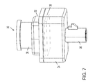
- FIG. 7 is a perspective view of a camera having a lens holder in accordance with the present invention.
- a vehicle vision system and/or driver assist system and/or object detection system and/or alert system operates to capture images exterior of the vehicle and may process the captured image data to display images and to detect objects at or near the vehicle and in the predicted path of the vehicle, such as to assist a driver of the vehicle in maneuvering the vehicle in a rearward direction.
- the vision system includes an image processor or image processing system that is operable to receive image data from one or more cameras and provide an output to a display device for displaying images representative of the captured image data.
- the vision system may provide a top down or bird's eye or surround view display and may provide a displayed image that is representative of the subject vehicle, and optionally with the displayed image being customized to at least partially correspond to the actual subject vehicle.
- a vehicle 10 includes an imaging system or vision system 12 that includes at least one exterior facing imaging sensor or camera, such as a rearward facing imaging sensor or camera 14 a (and the system may optionally include multiple exterior facing imaging sensors or cameras, such as a forwardly facing camera 14 b at the front (or at the windshield) of the vehicle, and a sidewardly/rearwardly facing camera 14 c , 14 d at respective sides of the vehicle), which captures images exterior of the vehicle, with the camera having a lens for focusing images at or onto an imaging array or imaging plane or imager of the camera ( FIG. 1 ).
- an imaging system or vision system 12 that includes at least one exterior facing imaging sensor or camera, such as a rearward facing imaging sensor or camera 14 a (and the system may optionally include multiple exterior facing imaging sensors or cameras, such as a forwardly facing camera 14 b at the front (or at the windshield) of the vehicle, and a sidewardly/rearwardly facing camera 14 c , 14 d at respective sides of the vehicle), which captures images
- the vision system 12 includes a control or electronic control unit (ECU) or processor 18 that is operable to process image data captured by the cameras and may provide displayed images at a display device 16 for viewing by the driver of the vehicle (although shown in FIG. 1 as being part of or incorporated in or at an interior rearview mirror assembly 20 of the vehicle, the control and/or the display device may be disposed elsewhere at or in the vehicle).
- the data transfer or signal communication from the camera to the ECU may comprise any suitable data or communication link, such as a vehicle network bus or the like of the equipped vehicle.
- the camera or camera module 22 includes an imager 24 at an image plane and a lens holder or lens barrel 26 that holds the lens relative to the imager.
- the lens barrel is positioned relative to the imager's image plane to provide the desired focusing of images at the image plane by the lens.
- the camera module 30 FIG. 7
- the camera module 30 may include a front housing portion 32 and a rear housing portion 34 , with the lens barrel 26 mounting at the front housing portion and with an electrical connector 36 (for connecting to a vehicle wiring harness or the like) provided at the rear housing portion.
- the front and/or rear housing portions support and house a circuit element or printed circuit board 38 therein, with the circuit element having the imager (and associated circuitry) disposed thereat.
- the lens barrel attaches or mounts to the front housing portion such that, when so attached, the lens may focus (or slightly blur) images at the image plane of the imager.
- the flange of the lens barrel may engage corresponding structure at the front housing portion during the assembly process to locate the lens barrel and lens relative to the imager and image plane.
- the plastic lens barrel is used widely in the camera industry for its low cost and easy mass production by plastic molding injection technology.
- One challenge for plastic lens barrel is to keep the flange focus length (FFL) consistent.
- the plastic injection molding process (for injection molding the plastic lens barrel) requires that the molding tooling to have a certain angle to ease the release of the part from the tooling after the part is molded.
- the flange surface 26 b of the flange 26 a is angled relative to a plane that bisects the lens barrel and has its normal axis or normal vector parallel to the axis of the lens barrel.
- the flange surface 26 b may be at about a five degree angle relative to such a plane.
- This angled part or flange results in the flange surface not being made as a flat and uniform surface. That introduces large uncertainties for FFL.
- the FFL large tolerance will cause large camera focus variations during camera assembly.
- the present invention provides a structure that keeps the lens Flange Focus Length (FFL) consistent for lens manufacturing, testing, and camera module assembly.
- the present invention provides a structure 28 on the lens barrel flange 26 a to ensure a flat surface portion, while still forming the flange with its main surface having a small angle that meets the molding tooling release requirement (such as about a 5 degree angle from the plane that is perpendicular to the cylindrical body wall of the lens holder, such as shown in FIG. 6 ).
- the structure may be integrally molded with the lens barrel or holder during the injection molding process that molds and forms the lens holder.
- the flat surfaces or structures or bosses 28 are established at the surface 26 b of the flange 26 a that faces the imager 24 when the lens barrel 26 is assembled at the imager and camera module.
- the planar flat surface resides in a plane that is normal to the axis of the lens barrel and thus, when the lens barrel is positioned relative to the imager for assembling the camera module, the plane of the planar flat surface is parallel to the image plane of the imager.
- the flat surface may be set at a predetermined FFL relative to the image plane, whereby the lens is positioned so as to substantially focus images at the image plane.
- the planar flat structure and surface is formed at the angled surface of the lens barrel flange so that the planar flat structure is angled relative to the angled surface.
- the planar flat surface or structure protrudes from the angled surface towards the imager in order to provide the planar or flat surface that faces and is parallel to the image plane.
- the flat structure can be established as any suitable shape and at any suitable position at the barrel flange, so long as the flat structure is flat and provides a planar or flat surface that is normal to the axis of the lens barrel (in other words, the flat surface resides in a plane that is normal to the axis of the lens barrel and thus that is parallel to the image plane of the imager) so as to provide a uniform or consistent flat surface for establishing the proper FFL during camera assembly.
- the flat structure may be formed at or added to a different surface of the lens barrel, such as to a different flange or the like of the lens barrel, as long as the flat surface or structure is used to determine the camera focus length during assembly of the camera module.
- the camera or sensor may comprise any suitable camera or sensor.
- the camera may comprise a “smart camera” that includes the imaging sensor array and associated circuitry and image processing circuitry and electrical connectors and the like as part of a camera module, such as by utilizing aspects of the vision systems described in International Publication Nos. WO 2013/081984 and/or WO 2013/081985, which are hereby incorporated herein by reference in their entireties.
- the system includes an image processor operable to process image data captured by the camera or cameras, such as for detecting objects or other vehicles or pedestrians or the like in the field of view of one or more of the cameras.
- the image processor may comprise an EyeQ2 or EyeQ3 image processing chip available from Mobileye Vision Technologies Ltd. of Jerusalem, Israel, and may include object detection software (such as the types described in U.S. Pat. Nos. 7,855,755; 7,720,580; and/or 7,038,577, which are hereby incorporated herein by reference in their entireties), and may analyze image data to detect vehicles and/or other objects.
- the system may generate an alert to the driver of the vehicle and/or may generate an overlay at the displayed image to highlight or enhance display of the detected object or vehicle, in order to enhance the driver's awareness of the detected object or vehicle or hazardous condition during a driving maneuver of the equipped vehicle.
- the vehicle may include any type of sensor or sensors, such as imaging sensors or radar sensors or lidar sensors or ladar sensors or ultrasonic sensors or the like.
- the imaging sensor or camera may capture image data for image processing and may comprise any suitable camera or sensing device, such as, for example, a two dimensional array of a plurality of photosensor elements arranged in at least 640 columns and 480 rows (at least a 640 ⁇ 480 imaging array, such as a megapixel imaging array or the like), with a respective lens focusing images onto respective portions of the array.
- the photosensor array may comprise a plurality of photosensor elements arranged in a photosensor array having rows and columns.
- the imaging array has at least 300,000 photosensor elements or pixels, more preferably at least 500,000 photosensor elements or pixels and more preferably at least 1 million photosensor elements or pixels.
- the imaging array may capture color image data, such as via spectral filtering at the array, such as via an RGB (red, green and blue) filter or via a red/red complement filter or such as via an RCC (red, clear, clear) filter or the like.
- the logic and control circuit of the imaging sensor may function in any known manner, and the image processing and algorithmic processing may comprise any suitable means for processing the images and/or image data.
- the vision system and/or processing and/or camera and/or circuitry may utilize aspects described in U.S. Pat. Nos. 7,005,974; 5,760,962; 5,877,897; 5,796,094; 5,949,331; 6,222,447; 6,302,545; 6,396,397; 6,498,620; 6,523,964; 6,611,202; 6,201,642; 6,690,268; 6,717,610; 6,757,109; 6,802,617; 6,806,452; 6,822,563; 6,891,563; 6,946,978; 7,859,565; 5,550,677; 5,670,935; 6,636,258; 7,145,519; 7,161,616; 7,230,640; 7,248,283; 7,295,229; 7,301,466; 7,592,928; 7,881,496; 7,720,580; 7,038,577; 6,882,287; 5,929,786 and/or 5,786,
- the system may communicate with other communication systems via any suitable means, such as by utilizing aspects of the systems described in International Publication Nos. WO/2010/144900; WO 2013/043661 and/or WO 2013/081985, and/or U.S. patent application Ser. No. 13/202,005, filed Aug. 17, 2011, now U.S. Pat. No. 9,126,525, which are hereby incorporated herein by reference in their entireties.
- the imaging device and control and image processor and any associated illumination source may comprise any suitable components, and may utilize aspects of the cameras and vision systems described in U.S. Pat. Nos. 5,550,677; 5,877,897; 6,498,620; 5,670,935; 5,796,094; 6,396,397; 6,806,452; 6,690,268; 7,005,974; 7,937,667; 7,123,168; 7,004,606; 6,946,978; 7,038,577; 6,353,392; 6,320,176; 6,313,454 and 6,824,281, and/or International Publication Nos.
- WO 2010/099416 WO 2011/028686; and/or WO 2013/016409, and/or U.S. Pat. Publication Nos. US-2013-0002873 and/or US 2010-0020170, which are all hereby incorporated herein by reference in their entireties.
- the camera or cameras may comprise any suitable cameras or imaging sensors or camera modules, and may utilize aspects of the cameras or sensors described in U.S. Publication No. US-2009-0244361 and/or U.S. Pat. Nos. 8,542,451; 7,965,336 and/or 7,480,149, which are hereby incorporated herein by reference in their entireties.
- the imaging array sensor may comprise any suitable sensor, and may utilize various imaging sensors or imaging array sensors or cameras or the like, such as a CMOS imaging array sensor, a CCD sensor or other sensors or the like, such as the types described in U.S. Pat. Nos.
- the camera module and circuit chip or board and imaging sensor may be implemented and operated in connection with various vehicular vision-based systems, and/or may be operable utilizing the principles of such other vehicular systems, such as a vehicle headlamp control system, such as the type disclosed in U.S. Pat. Nos. 5,796,094; 6,097,023; 6,320,176; 6,559,435; 6,831,261; 7,004,606; 7,339,149 and/or 7,526,103, which are all hereby incorporated herein by reference in their entireties, a rain sensor, such as the types disclosed in commonly assigned U.S. Pat. Nos.
- a vehicle vision system such as a forwardly, sidewardly or rearwardly directed vehicle vision system utilizing principles disclosed in U.S. Pat. Nos.
- a reverse or sideward imaging system such as for a lane change assistance system or lane departure warning system or for a blind spot or object detection system, such as imaging or detection systems of the types disclosed in U.S. Pat. Nos. 7,881,496; 7,720,580; 7,038,577; 5,929,786 and/or 5,786,772, which are hereby incorporated herein by reference in their entireties, a video device for internal cabin surveillance and/or video telephone function, such as disclosed in U.S. Pat. Nos. 5,760,962; 5,877,897; 6,690,268 and/or 7,370,983, and/or U.S. Publication No.
- the circuit board or chip may include circuitry for the imaging array sensor and or other electronic accessories or features, such as by utilizing compass-on-a-chip or EC driver-on-a-chip technology and aspects such as described in U.S. Pat. Nos. 7,255,451 and/or 7,480,149, and/or U.S. Publication No. US-2006-0061008 and/or U.S. patent application Ser. No. 12/578,732, filed Oct. 14, 2009, now U.S. Pat. No. 9,487,144, which are hereby incorporated herein by reference in their entireties.
- the vision system may include a display for displaying images captured by one or more of the imaging sensors for viewing by the driver of the vehicle while the driver is normally operating the vehicle.
- the vision system may include a video display device disposed at or in the interior rearview mirror assembly of the vehicle, such as by utilizing aspects of the video mirror display systems described in U.S. Pat. No. 6,690,268 and/or U.S. patent application Ser. No. 13/333,337, filed Dec. 21, 2011, now U.S. Pat. No. 9,264,672, which are hereby incorporated herein by reference in their entireties.
- the video mirror display may comprise any suitable devices and systems and optionally may utilize aspects of the compass display systems described in U.S. Pat. Nos.
- the video mirror display screen or device may be operable to display images captured by a rearward viewing camera of the vehicle during a reversing maneuver of the vehicle (such as responsive to the vehicle gear actuator being placed in a reverse gear position or the like) to assist the driver in backing up the vehicle, and optionally may be operable to display the compass heading or directional heading character or icon when the vehicle is not undertaking a reversing maneuver, such as when the vehicle is being driven in a forward direction along a road (such as by utilizing aspects of the display system described in International Publication No. WO 2012/051500, which is hereby incorporated herein by reference in its entirety).
- the vision system (utilizing the forward facing camera and a rearward facing camera and other cameras disposed at the vehicle with exterior fields of view) may be part of or may provide a display of a top-down view or birds-eye view system of the vehicle or a surround view at the vehicle, such as by utilizing aspects of the vision systems described in International Publication Nos. WO 2010/099416; WO 2011/028686; WO2012/075250; WO 2013/019795; WO 2012/075250; WO 2012/145822; WO 2013/081985; WO 2013/086249 and/or WO 2013/109869, which are hereby incorporated herein by reference in their entireties.
- a video mirror display may be disposed rearward of and behind the reflective element assembly and may comprise a display such as the types disclosed in U.S. Pat. Nos. 5,530,240; 6,329,925; 7,855,755; 7,626,749; 7,581,859; 7,446,650; 7,370,983; 7,338,177; 7,274,501; 7,255,451; 7,195,381; 7,184,190; 5,668,663; 5,724,187 and/or 6,690,268, and/or in U.S. Publication Nos. US-2006-0061008 and/or US-2006-0050018, which are all hereby incorporated herein by reference in their entireties.
- the display is viewable through the reflective element when the display is activated to display information.
- the display element may be any type of display element, such as a vacuum fluorescent (VF) display element, a light emitting diode (LED) display element, such as an organic light emitting diode (OLED) or an inorganic light emitting diode, an electroluminescent (EL) display element, a liquid crystal display (LCD) element, a video screen display element or backlit thin film transistor (TFT) display element or the like, and may be operable to display various information (as discrete characters, icons or the like, or in a multi-pixel manner) to the driver of the vehicle, such as passenger side inflatable restraint (PSIR) information, tire pressure status, and/or the like.
- PSIR passenger side inflatable restraint
- the mirror assembly and/or display may utilize aspects described in U.S. Pat. Nos. 7,184,190; 7,255,451; 7,446,924 and/or 7,338,177, which are all hereby incorporated herein by reference in their entireties.
- the thicknesses and materials of the coatings on the substrates of the reflective element may be selected to provide a desired color or tint to the mirror reflective element, such as a blue colored reflector, such as is known in the art and such as described in U.S. Pat. Nos. 5,910,854; 6,420,036 and/or 7,274,501, which are hereby incorporated herein by reference in their entireties.
- the display or displays and any associated user inputs may be associated with various accessories or systems, such as, for example, a tire pressure monitoring system or a passenger air bag status or a garage door opening system or a telematics system or any other accessory or system of the mirror assembly or of the vehicle or of an accessory module or console of the vehicle, such as an accessory module or console of the types described in U.S. Pat. Nos. 7,289,037; 6,877,888; 6,824,281; 6,690,268; 6,672,744; 6,386,742 and/or 6,124,886, and/or U.S. Publication No. US-2006-0050018, which are hereby incorporated herein by reference in their entireties.
Abstract
A camera assembly for a vehicle vision system includes an imager, a lens and a lens holder. The imager is disposed at a circuit element. The lens holder includes a barrel portion that houses the lens. The lens holder is positioned relative to the imager and includes a flange protruding outward from the barrel portion. The flange of the lens holder includes a generally flat structure having a planar surface that resides in a plane that is normal to an axis of the barrel portion. The lens holder is positioned relative to the imager such that the plane is parallel to the image plane and such that the planar flat surface is a predetermined distance from the image plane, thereby positioning the lens at a desired location relative to the imager.
Description
The present application is related to U.S. provisional application Ser. No. 61/952,335, filed Mar. 13, 2014, which is hereby incorporated herein by reference in its entirety.
The present invention relates generally to a vehicle vision system for a vehicle and, more particularly, to a vehicle vision system that utilizes one or more cameras at a vehicle.
Use of imaging sensors in vehicle imaging systems is common and known. Examples of such known systems are described in U.S. Pat. Nos. 5,949,331; 5,670,935 and/or 5,550,677, which are hereby incorporated herein by reference in their entireties.
The present invention provides a collision avoidance system or vision system or imaging system for a vehicle that utilizes one or more cameras (preferably one or more CMOS cameras) to capture image data representative of images exterior of the vehicle. The camera or camera module includes an imager (such as an imaging array of photosensing pixels established at or disposed at a circuit board or element) and a lens that focuses or at least substantially focuses images at the image plane of the imager. The lens is held in a lens holder or barrel, which is mounted at the camera (such as at a front housing portion of the camera module) and relative to the imager so as to provide focusing of images at the image plane. The lens holder includes a generally planar or flat structure that is formed to have a flat surface at a known location relative to the lens, so that, when the camera module is assembled, the lens holder is positioned with the flat structure a predetermined distance to the image plane of the imager so that the lens focuses the images at the imager. The generally flat structure is formed (such as by molding the generally flat structure with the lens holder and flange during an injection molding process) to provide a flat or planar surface that resides in a plane that is normal to an axis of the lens and that, when the lens holder is positioned at the imager, is parallel to the image plane of the imager.
These and other objects, advantages, purposes and features of the present invention will become apparent upon review of the following specification in conjunction with the drawings.
A vehicle vision system and/or driver assist system and/or object detection system and/or alert system operates to capture images exterior of the vehicle and may process the captured image data to display images and to detect objects at or near the vehicle and in the predicted path of the vehicle, such as to assist a driver of the vehicle in maneuvering the vehicle in a rearward direction. The vision system includes an image processor or image processing system that is operable to receive image data from one or more cameras and provide an output to a display device for displaying images representative of the captured image data. Optionally, the vision system may provide a top down or bird's eye or surround view display and may provide a displayed image that is representative of the subject vehicle, and optionally with the displayed image being customized to at least partially correspond to the actual subject vehicle.
Referring now to the drawings and the illustrative embodiments depicted therein, a vehicle 10 includes an imaging system or vision system 12 that includes at least one exterior facing imaging sensor or camera, such as a rearward facing imaging sensor or camera 14 a (and the system may optionally include multiple exterior facing imaging sensors or cameras, such as a forwardly facing camera 14 b at the front (or at the windshield) of the vehicle, and a sidewardly/rearwardly facing camera 14 c, 14 d at respective sides of the vehicle), which captures images exterior of the vehicle, with the camera having a lens for focusing images at or onto an imaging array or imaging plane or imager of the camera (FIG. 1 ). The vision system 12 includes a control or electronic control unit (ECU) or processor 18 that is operable to process image data captured by the cameras and may provide displayed images at a display device 16 for viewing by the driver of the vehicle (although shown in FIG. 1 as being part of or incorporated in or at an interior rearview mirror assembly 20 of the vehicle, the control and/or the display device may be disposed elsewhere at or in the vehicle). The data transfer or signal communication from the camera to the ECU may comprise any suitable data or communication link, such as a vehicle network bus or the like of the equipped vehicle.
As shown in FIGS. 2 and 3 , the camera or camera module 22 includes an imager 24 at an image plane and a lens holder or lens barrel 26 that holds the lens relative to the imager. During assembly of the camera module, the lens barrel is positioned relative to the imager's image plane to provide the desired focusing of images at the image plane by the lens. For example, the camera module 30 (FIG. 7 ) may include a front housing portion 32 and a rear housing portion 34, with the lens barrel 26 mounting at the front housing portion and with an electrical connector 36 (for connecting to a vehicle wiring harness or the like) provided at the rear housing portion. The front and/or rear housing portions support and house a circuit element or printed circuit board 38 therein, with the circuit element having the imager (and associated circuitry) disposed thereat. The lens barrel attaches or mounts to the front housing portion such that, when so attached, the lens may focus (or slightly blur) images at the image plane of the imager. For example, the flange of the lens barrel may engage corresponding structure at the front housing portion during the assembly process to locate the lens barrel and lens relative to the imager and image plane.
The plastic lens barrel is used widely in the camera industry for its low cost and easy mass production by plastic molding injection technology. One challenge for plastic lens barrel is to keep the flange focus length (FFL) consistent. The plastic injection molding process (for injection molding the plastic lens barrel) requires that the molding tooling to have a certain angle to ease the release of the part from the tooling after the part is molded. For example, and as can be seen in FIGS. 3 and 6 , the flange surface 26 b of the flange 26 a is angled relative to a plane that bisects the lens barrel and has its normal axis or normal vector parallel to the axis of the lens barrel. For example, the flange surface 26 b may be at about a five degree angle relative to such a plane.
This angled part or flange results in the flange surface not being made as a flat and uniform surface. That introduces large uncertainties for FFL. The FFL large tolerance will cause large camera focus variations during camera assembly.
The present invention provides a structure that keeps the lens Flange Focus Length (FFL) consistent for lens manufacturing, testing, and camera module assembly. The present invention provides a structure 28 on the lens barrel flange 26 a to ensure a flat surface portion, while still forming the flange with its main surface having a small angle that meets the molding tooling release requirement (such as about a 5 degree angle from the plane that is perpendicular to the cylindrical body wall of the lens holder, such as shown in FIG. 6 ). The structure may be integrally molded with the lens barrel or holder during the injection molding process that molds and forms the lens holder.
As shown in FIGS. 2-6 , the flat surfaces or structures or bosses 28 are established at the surface 26 b of the flange 26 a that faces the imager 24 when the lens barrel 26 is assembled at the imager and camera module. The planar flat surface resides in a plane that is normal to the axis of the lens barrel and thus, when the lens barrel is positioned relative to the imager for assembling the camera module, the plane of the planar flat surface is parallel to the image plane of the imager. As shown in FIGS. 3 and 6 , when the lens barrel is positioned relative to the imager for assembling the camera module, the flat surface may be set at a predetermined FFL relative to the image plane, whereby the lens is positioned so as to substantially focus images at the image plane.
In the illustrated embodiment, the planar flat structure and surface is formed at the angled surface of the lens barrel flange so that the planar flat structure is angled relative to the angled surface. The planar flat surface or structure protrudes from the angled surface towards the imager in order to provide the planar or flat surface that faces and is parallel to the image plane. Although shown as a pair of flat structures extending partially along the angled surface of the barrel flange, the flat structure can be established as any suitable shape and at any suitable position at the barrel flange, so long as the flat structure is flat and provides a planar or flat surface that is normal to the axis of the lens barrel (in other words, the flat surface resides in a plane that is normal to the axis of the lens barrel and thus that is parallel to the image plane of the imager) so as to provide a uniform or consistent flat surface for establishing the proper FFL during camera assembly.
Optionally, the flat structure may be formed at or added to a different surface of the lens barrel, such as to a different flange or the like of the lens barrel, as long as the flat surface or structure is used to determine the camera focus length during assembly of the camera module.
The camera or sensor may comprise any suitable camera or sensor. Optionally, the camera may comprise a “smart camera” that includes the imaging sensor array and associated circuitry and image processing circuitry and electrical connectors and the like as part of a camera module, such as by utilizing aspects of the vision systems described in International Publication Nos. WO 2013/081984 and/or WO 2013/081985, which are hereby incorporated herein by reference in their entireties.
The system includes an image processor operable to process image data captured by the camera or cameras, such as for detecting objects or other vehicles or pedestrians or the like in the field of view of one or more of the cameras. For example, the image processor may comprise an EyeQ2 or EyeQ3 image processing chip available from Mobileye Vision Technologies Ltd. of Jerusalem, Israel, and may include object detection software (such as the types described in U.S. Pat. Nos. 7,855,755; 7,720,580; and/or 7,038,577, which are hereby incorporated herein by reference in their entireties), and may analyze image data to detect vehicles and/or other objects. Responsive to such image processing, and when an object or other vehicle is detected, the system may generate an alert to the driver of the vehicle and/or may generate an overlay at the displayed image to highlight or enhance display of the detected object or vehicle, in order to enhance the driver's awareness of the detected object or vehicle or hazardous condition during a driving maneuver of the equipped vehicle.
The vehicle may include any type of sensor or sensors, such as imaging sensors or radar sensors or lidar sensors or ladar sensors or ultrasonic sensors or the like. The imaging sensor or camera may capture image data for image processing and may comprise any suitable camera or sensing device, such as, for example, a two dimensional array of a plurality of photosensor elements arranged in at least 640 columns and 480 rows (at least a 640×480 imaging array, such as a megapixel imaging array or the like), with a respective lens focusing images onto respective portions of the array. The photosensor array may comprise a plurality of photosensor elements arranged in a photosensor array having rows and columns. Preferably, the imaging array has at least 300,000 photosensor elements or pixels, more preferably at least 500,000 photosensor elements or pixels and more preferably at least 1 million photosensor elements or pixels. The imaging array may capture color image data, such as via spectral filtering at the array, such as via an RGB (red, green and blue) filter or via a red/red complement filter or such as via an RCC (red, clear, clear) filter or the like. The logic and control circuit of the imaging sensor may function in any known manner, and the image processing and algorithmic processing may comprise any suitable means for processing the images and/or image data.
For example, the vision system and/or processing and/or camera and/or circuitry may utilize aspects described in U.S. Pat. Nos. 7,005,974; 5,760,962; 5,877,897; 5,796,094; 5,949,331; 6,222,447; 6,302,545; 6,396,397; 6,498,620; 6,523,964; 6,611,202; 6,201,642; 6,690,268; 6,717,610; 6,757,109; 6,802,617; 6,806,452; 6,822,563; 6,891,563; 6,946,978; 7,859,565; 5,550,677; 5,670,935; 6,636,258; 7,145,519; 7,161,616; 7,230,640; 7,248,283; 7,295,229; 7,301,466; 7,592,928; 7,881,496; 7,720,580; 7,038,577; 6,882,287; 5,929,786 and/or 5,786,772, and/or International Publication Nos. WO 2011/028686; WO 2010/099416; WO 2012/061567; WO 2012/068331; WO 2012/075250; WO 2012/103193; WO 2012/0116043; WO 2012/0145313; WO 2012/0145501; WO 2012/145818; WO 2012/145822; WO 2012/158167; WO 2012/075250; WO 2012/0116043; WO 2012/0145501; WO 2012/154919; WO 2013/019707; WO 2013/016409; WO 2013/019795; WO 2013/067083; WO 2013/070539; WO 2013/043661; WO 2013/048994; WO 2013/063014, WO 2013/081984; WO 2013/081985; WO 2013/074604; WO 2013/086249; WO 2013/103548; WO 2013/109869; WO 2013/123161; WO 2013/126715; WO 2013/043661 and/or WO 2013/158592, which are all hereby incorporated herein by reference in their entireties. The system may communicate with other communication systems via any suitable means, such as by utilizing aspects of the systems described in International Publication Nos. WO/2010/144900; WO 2013/043661 and/or WO 2013/081985, and/or U.S. patent application Ser. No. 13/202,005, filed Aug. 17, 2011, now U.S. Pat. No. 9,126,525, which are hereby incorporated herein by reference in their entireties.
The imaging device and control and image processor and any associated illumination source, if applicable, may comprise any suitable components, and may utilize aspects of the cameras and vision systems described in U.S. Pat. Nos. 5,550,677; 5,877,897; 6,498,620; 5,670,935; 5,796,094; 6,396,397; 6,806,452; 6,690,268; 7,005,974; 7,937,667; 7,123,168; 7,004,606; 6,946,978; 7,038,577; 6,353,392; 6,320,176; 6,313,454 and 6,824,281, and/or International Publication Nos. WO 2010/099416; WO 2011/028686; and/or WO 2013/016409, and/or U.S. Pat. Publication Nos. US-2013-0002873 and/or US 2010-0020170, which are all hereby incorporated herein by reference in their entireties. The camera or cameras may comprise any suitable cameras or imaging sensors or camera modules, and may utilize aspects of the cameras or sensors described in U.S. Publication No. US-2009-0244361 and/or U.S. Pat. Nos. 8,542,451; 7,965,336 and/or 7,480,149, which are hereby incorporated herein by reference in their entireties. The imaging array sensor may comprise any suitable sensor, and may utilize various imaging sensors or imaging array sensors or cameras or the like, such as a CMOS imaging array sensor, a CCD sensor or other sensors or the like, such as the types described in U.S. Pat. Nos. 5,550,677; 5,670,935; 5,760,962; 5,715,093; 5,877,897; 6,922,292; 6,757,109; 6,717,610; 6,590,719; 6,201,642; 6,498,620; 5,796,094; 6,097,023; 6,320,176; 6,559,435; 6,831,261; 6,806,452; 6,396,397; 6,822,563; 6,946,978; 7,339,149; 7,038,577; 7,004,606; 7,720,580 and/or 7,965,336, and/or International Publication Nos. WO/2009/036176 and/or WO/2009/046268, which are all hereby incorporated herein by reference in their entireties.
The camera module and circuit chip or board and imaging sensor may be implemented and operated in connection with various vehicular vision-based systems, and/or may be operable utilizing the principles of such other vehicular systems, such as a vehicle headlamp control system, such as the type disclosed in U.S. Pat. Nos. 5,796,094; 6,097,023; 6,320,176; 6,559,435; 6,831,261; 7,004,606; 7,339,149 and/or 7,526,103, which are all hereby incorporated herein by reference in their entireties, a rain sensor, such as the types disclosed in commonly assigned U.S. Pat. Nos. 6,353,392; 6,313,454; 6,320,176 and/or 7,480,149, which are hereby incorporated herein by reference in their entireties, a vehicle vision system, such as a forwardly, sidewardly or rearwardly directed vehicle vision system utilizing principles disclosed in U.S. Pat. Nos. 5,550,677; 5,670,935; 5,760,962; 5,877,897; 5,949,331; 6,222,447; 6,302,545; 6,396,397; 6,498,620; 6,523,964; 6,611,202; 6,201,642; 6,690,268; 6,717,610; 6,757,109; 6,802,617; 6,806,452; 6,822,563; 6,891,563; 6,946,978 and/or 7,859,565, which are all hereby incorporated herein by reference in their entireties, a trailer hitching aid or tow check system, such as the type disclosed in U.S. Pat. No. 7,005,974, which is hereby incorporated herein by reference in its entirety, a reverse or sideward imaging system, such as for a lane change assistance system or lane departure warning system or for a blind spot or object detection system, such as imaging or detection systems of the types disclosed in U.S. Pat. Nos. 7,881,496; 7,720,580; 7,038,577; 5,929,786 and/or 5,786,772, which are hereby incorporated herein by reference in their entireties, a video device for internal cabin surveillance and/or video telephone function, such as disclosed in U.S. Pat. Nos. 5,760,962; 5,877,897; 6,690,268 and/or 7,370,983, and/or U.S. Publication No. US-2006-0050018, which are hereby incorporated herein by reference in their entireties, a traffic sign recognition system, a system for determining a distance to a leading or trailing vehicle or object, such as a system utilizing the principles disclosed in U.S. Pat. Nos. 6,396,397 and/or 7,123,168, which are hereby incorporated herein by reference in their entireties, and/or the like.
Optionally, the circuit board or chip may include circuitry for the imaging array sensor and or other electronic accessories or features, such as by utilizing compass-on-a-chip or EC driver-on-a-chip technology and aspects such as described in U.S. Pat. Nos. 7,255,451 and/or 7,480,149, and/or U.S. Publication No. US-2006-0061008 and/or U.S. patent application Ser. No. 12/578,732, filed Oct. 14, 2009, now U.S. Pat. No. 9,487,144, which are hereby incorporated herein by reference in their entireties.
Optionally, the vision system may include a display for displaying images captured by one or more of the imaging sensors for viewing by the driver of the vehicle while the driver is normally operating the vehicle. Optionally, for example, the vision system may include a video display device disposed at or in the interior rearview mirror assembly of the vehicle, such as by utilizing aspects of the video mirror display systems described in U.S. Pat. No. 6,690,268 and/or U.S. patent application Ser. No. 13/333,337, filed Dec. 21, 2011, now U.S. Pat. No. 9,264,672, which are hereby incorporated herein by reference in their entireties. The video mirror display may comprise any suitable devices and systems and optionally may utilize aspects of the compass display systems described in U.S. Pat. Nos. 7,370,983; 7,329,013; 7,308,341; 7,289,037; 7,249,860; 7,004,593; 4,546,551; 5,699,044; 4,953,305; 5,576,687; 5,632,092; 5,677,851; 5,708,410; 5,737,226; 5,802,727; 5,878,370; 6,087,953; 6,173,508; 6,222,460; 6,513,252 and/or 6,642,851, and/or European patent application, published Oct. 11, 2000 under Publication No. EP 0 1043566, and/or U.S. Publication No. US-2006-0061008, which are all hereby incorporated herein by reference in their entireties. Optionally, the video mirror display screen or device may be operable to display images captured by a rearward viewing camera of the vehicle during a reversing maneuver of the vehicle (such as responsive to the vehicle gear actuator being placed in a reverse gear position or the like) to assist the driver in backing up the vehicle, and optionally may be operable to display the compass heading or directional heading character or icon when the vehicle is not undertaking a reversing maneuver, such as when the vehicle is being driven in a forward direction along a road (such as by utilizing aspects of the display system described in International Publication No. WO 2012/051500, which is hereby incorporated herein by reference in its entirety).
Optionally, the vision system (utilizing the forward facing camera and a rearward facing camera and other cameras disposed at the vehicle with exterior fields of view) may be part of or may provide a display of a top-down view or birds-eye view system of the vehicle or a surround view at the vehicle, such as by utilizing aspects of the vision systems described in International Publication Nos. WO 2010/099416; WO 2011/028686; WO2012/075250; WO 2013/019795; WO 2012/075250; WO 2012/145822; WO 2013/081985; WO 2013/086249 and/or WO 2013/109869, which are hereby incorporated herein by reference in their entireties.
Optionally, a video mirror display may be disposed rearward of and behind the reflective element assembly and may comprise a display such as the types disclosed in U.S. Pat. Nos. 5,530,240; 6,329,925; 7,855,755; 7,626,749; 7,581,859; 7,446,650; 7,370,983; 7,338,177; 7,274,501; 7,255,451; 7,195,381; 7,184,190; 5,668,663; 5,724,187 and/or 6,690,268, and/or in U.S. Publication Nos. US-2006-0061008 and/or US-2006-0050018, which are all hereby incorporated herein by reference in their entireties. The display is viewable through the reflective element when the display is activated to display information. The display element may be any type of display element, such as a vacuum fluorescent (VF) display element, a light emitting diode (LED) display element, such as an organic light emitting diode (OLED) or an inorganic light emitting diode, an electroluminescent (EL) display element, a liquid crystal display (LCD) element, a video screen display element or backlit thin film transistor (TFT) display element or the like, and may be operable to display various information (as discrete characters, icons or the like, or in a multi-pixel manner) to the driver of the vehicle, such as passenger side inflatable restraint (PSIR) information, tire pressure status, and/or the like. The mirror assembly and/or display may utilize aspects described in U.S. Pat. Nos. 7,184,190; 7,255,451; 7,446,924 and/or 7,338,177, which are all hereby incorporated herein by reference in their entireties. The thicknesses and materials of the coatings on the substrates of the reflective element may be selected to provide a desired color or tint to the mirror reflective element, such as a blue colored reflector, such as is known in the art and such as described in U.S. Pat. Nos. 5,910,854; 6,420,036 and/or 7,274,501, which are hereby incorporated herein by reference in their entireties.
Optionally, the display or displays and any associated user inputs may be associated with various accessories or systems, such as, for example, a tire pressure monitoring system or a passenger air bag status or a garage door opening system or a telematics system or any other accessory or system of the mirror assembly or of the vehicle or of an accessory module or console of the vehicle, such as an accessory module or console of the types described in U.S. Pat. Nos. 7,289,037; 6,877,888; 6,824,281; 6,690,268; 6,672,744; 6,386,742 and/or 6,124,886, and/or U.S. Publication No. US-2006-0050018, which are hereby incorporated herein by reference in their entireties.
Changes and modifications in the specifically described embodiments can be carried out without departing from the principles of the invention, which is intended to be limited only by the scope of the appended claims, as interpreted according to the principles of patent law including the doctrine of equivalents.
Claims (20)
1. A camera assembly for a vision system of a vehicle, said camera assembly comprising:
an imager disposed at a circuit element, said imager comprising a pixelated imaging array having a plurality of photosensing elements;
a lens;
a lens holder comprising a barrel portion that houses said lens;
wherein said lens holder is positioned relative to an image plane of said imager;
wherein said lens holder comprises a flange protruding outward from said barrel portion;
wherein said flange comprises an angled surface portion that faces said image plane of said imager, and wherein said flange comprises a planar surface portion that protrudes from said angled surface portion;
wherein said planar surface portion of said flange of said lens holder comprises a flat structure that has a planar surface that resides in a structure plane that is normal to an axis of said barrel portion; and
wherein said lens holder is positioned relative to said image plane of said imager such that said planar surface of said planar surface portion is parallel to said image plane of said imager and such that said planar surface is a predetermined distance from said image plane, thereby positioning said lens at a predetermined location relative to said image plane of said imager.
2. The camera assembly of claim 1 , wherein said angled surface portion of said flange of said lens holder has an angled surface that is angled relative to said structure plane of said planar surface of said planar surface portion.
3. The camera assembly of claim 2 , wherein a portion of an angled surface of said angled surface portion is exposed and not encompassed by said planar surface portion.
4. The camera assembly of claim 1 , wherein said flange comprises a circular-shaped flange protruding radially outward from the circular-shaped lens holder.
5. The camera assembly of claim 4 , wherein said planar surface portion comprises a pair of strips having planar surfaces that extend at least partially across said circular-shaped flange.
6. The camera assembly of claim 5 , wherein said circular-shaped flange has an angled surface that is angled relative to said structure plane of said planar surfaces, and wherein said strips are established at said angled surface portion and protrude from said angled surface portion of said generally circular-shaped flange.
7. The camera assembly of claim 1 , wherein said planar surface portion comprises at least two flat structures having planar surfaces that extend at least partially across said flange.
8. The camera assembly of claim 7 , wherein said angled surface portion of said flange of said lens holder has an angled surface that is angled relative to said structure plane of said planar surfaces, and wherein said flat structures are established at said angled surface and protrude from said angled surface portion of said flange.
9. The camera assembly of claim 8 , wherein a portion of said angled surface is exposed and not encompassed by said flat structures.
10. The camera assembly of claim 1 , wherein said lens holder is positioned relative to said image plane of said imager so that said lens focuses images at an image plane of said imager.
11. The camera assembly of claim 1 , wherein said planar surface portion is integrally molded with said flange and said barrel portion via an injection molding process.
12. The camera assembly of claim 1 , comprising a front housing portion and a rear housing portion, wherein said lens holder is attached at said front housing portion and wherein said imager and said circuit element are housed in said front and rear housing portions.
13. A camera assembly for a vision system of a vehicle, said camera assembly comprising:
a front housing portion and a rear housing portion;
an imager disposed at a circuit element housed in said front and rear housing portions, said imager comprising a pixelated imaging array having a plurality of photosensing elements;
a lens;
a lens holder comprising a barrel portion that houses said lens;
wherein said lens holder is attached at said front housing portion;
wherein said lens holder, when attached at said front housing portion, is positioned relative to an image plane of said imager;
wherein said lens holder comprises a flange protruding outward from said barrel portion and wherein said flange has an angled surface portion having an angled surface that is angled relative to a structure plane that is normal to an axis of said barrel portion;
wherein said flange of said lens holder includes a flat structure that is established at said angled surface portion and protrudes from said angled surface portion of said flange, and wherein said flat structure comprises a planar surface that resides in the structure plane that is normal to the axis of said barrel portion;
wherein a portion of said angled surface portion is exposed and not encompassed by said generally flat structure; and
wherein said lens holder is positioned relative to said image plane of said imager such that said structure plane is parallel to said image plane of said imager and such that said planar surface is a predetermined distance from said image plane, thereby positioning said lens at a predetermined location relative to said image plane of said imager.
14. The camera assembly of claim 13 , wherein said flange comprises a circular-shaped flange protruding radially outward from the circular-shaped lens holder.
15. The camera assembly of claim 14 , wherein said flat structure comprises a pair of strips having planar surfaces that extend at least partially across said circular-shaped flange.
16. The camera assembly of claim 13 , wherein said lens holder is attached to said front housing portion and positioned relative to said image plane of said imager so that said lens focuses images at an image plane of said imager.
17. The camera assembly of claim 13 , wherein said flat structure is integrally molded with said flange and said barrel portion via an injection molding process.
18. A camera assembly for a vision system of a vehicle, said camera assembly comprising:
a front housing portion and a rear housing portion;
an imager disposed at a circuit element housed in said front and rear housing portions, said imager comprising a pixelated imaging array having a plurality of photosensing elements;
a lens;
a lens holder comprising a barrel portion that houses said lens;
wherein said lens holder is attached at said front housing portion;
wherein said lens holder, when attached at said front housing portion, is positioned relative to an image plane of said imager;
wherein said lens holder comprises a flange protruding radially outward from said barrel portion, and wherein said flange has an angled surface portion that has an angled surface that is angled relative to a structure plane that is normal to an axis of said barrel portion;
wherein said flange of said lens holder includes flat structures that are established at said angled surface portion and protrude from said angled surface portion of said flange, and wherein said flat structures comprise at least two spaced apart structures having planar surfaces that reside in the structure plane that is normal to the axis of said barrel portion, and wherein said angled surface of said angled surface portion is exposed and not encompassed by said flat structures; and
wherein said lens holder is positioned relative to said image plane of said imager such that said structure plane is parallel to said image plane of said imager and such that said planar surfaces are a predetermined distance from said image plane, thereby positioning said lens at a predetermined location relative to said image plane of said imager.
19. The camera assembly of claim 18 , wherein said lens holder is positioned relative to said image plane of said imager so that said lens focuses images at an image plane of said imager.
20. The camera assembly of claim 18 , wherein said flat structures are integrally molded with said flange and said barrel portion via an injection molding process.
Priority Applications (1)
| Application Number | Priority Date | Filing Date | Title |
|---|---|---|---|
| US14/645,546 US9749509B2 (en) | 2014-03-13 | 2015-03-12 | Camera with lens for vehicle vision system |
Applications Claiming Priority (2)
| Application Number | Priority Date | Filing Date | Title |
|---|---|---|---|
| US201461952335P | 2014-03-13 | 2014-03-13 | |
| US14/645,546 US9749509B2 (en) | 2014-03-13 | 2015-03-12 | Camera with lens for vehicle vision system |
Publications (2)
| Publication Number | Publication Date |
|---|---|
| US20150264234A1 US20150264234A1 (en) | 2015-09-17 |
| US9749509B2 true US9749509B2 (en) | 2017-08-29 |
Family
ID=54070370
Family Applications (1)
| Application Number | Title | Priority Date | Filing Date |
|---|---|---|---|
| US14/645,546 Active 2035-10-02 US9749509B2 (en) | 2014-03-13 | 2015-03-12 | Camera with lens for vehicle vision system |
Country Status (1)
| Country | Link |
|---|---|
| US (1) | US9749509B2 (en) |
Cited By (1)
| Publication number | Priority date | Publication date | Assignee | Title |
|---|---|---|---|---|
| US20180098033A1 (en) * | 2016-10-03 | 2018-04-05 | Magna Electronics Inc. | Vehicle camera with compliant coaxial connector |
Families Citing this family (4)
| Publication number | Priority date | Publication date | Assignee | Title |
|---|---|---|---|---|
| DE102015008042B3 (en) * | 2015-06-23 | 2016-12-15 | Mekra Lang Gmbh & Co. Kg | Display device for vehicles, in particular commercial vehicles |
| DE102015121396A1 (en) * | 2015-12-09 | 2017-06-14 | Connaught Electronics Ltd. | Camera with a housing for shielding electromagnetic radiation and motor vehicle |
| JP6601273B2 (en) * | 2016-03-03 | 2019-11-06 | 株式会社デンソー | Camera device |
| EP3462550B1 (en) * | 2017-10-02 | 2021-01-27 | Hosiden Corporation | Connector module and onboard camera using the same |
Citations (121)
| Publication number | Priority date | Publication date | Assignee | Title |
|---|---|---|---|---|
| US4712879A (en) | 1986-04-02 | 1987-12-15 | Donnelly Corporation | Electrochromic mirror |
| US4786966A (en) | 1986-07-10 | 1988-11-22 | Varo, Inc. | Head mounted video display and remote camera system |
| US5073012A (en) | 1988-02-12 | 1991-12-17 | Donnelly Corporation | Anti-scatter, ultraviolet protected, anti-misting, electro-optical assemblies |
| US5076673A (en) | 1990-08-10 | 1991-12-31 | Donnelly Corporation | Prolonged coloration electrochromic assembly |
| US5115346A (en) | 1988-02-12 | 1992-05-19 | Donnelly Corporation | Anti-scatter, ultraviolet protected, anti-misting, electro-optical rearview mirror |
| US5140455A (en) | 1989-11-29 | 1992-08-18 | Donnelly Corporation | High performance electrochemichromic solutions and devices thereof |
| US5142407A (en) | 1989-12-22 | 1992-08-25 | Donnelly Corporation | Method of reducing leakage current in electrochemichromic solutions and solutions based thereon |
| US5151816A (en) | 1989-12-29 | 1992-09-29 | Donnelly Corporation | Method for reducing current leakage and enhancing uv stability in electrochemichromic solutions and devices |
| US5253109A (en) | 1992-04-27 | 1993-10-12 | Donnelly Corporation | Electro-optic device with constant light transmitting area |
| US5371659A (en) | 1993-02-01 | 1994-12-06 | Donnelly Corporation | Remote-actuated exterior vehicle security light |
| US5497306A (en) | 1993-02-01 | 1996-03-05 | Donnelly Corporation | Exterior vehicle security light |
| JPH0884277A (en) | 1994-09-09 | 1996-03-26 | Mitsubishi Electric Corp | On-vehicle camera |
| US5525264A (en) | 1992-07-15 | 1996-06-11 | Donnelly Corporation | Precursor solutions for forming coatings |
| US5550677A (en) | 1993-02-26 | 1996-08-27 | Donnelly Corporation | Automatic rearview mirror system using a photosensor array |
| US5559556A (en) | 1992-06-30 | 1996-09-24 | Icl Systems Ab | Apparatus for connecting an image sensor and an optical unit to a circuit board so that they are properly aligned |
| US5610756A (en) | 1990-11-26 | 1997-03-11 | Donnelly Corporation | Electrochromic mirror for vehicles |
| US5668663A (en) | 1994-05-05 | 1997-09-16 | Donnelly Corporation | Electrochromic mirrors and devices |
| US5669699A (en) | 1994-11-02 | 1997-09-23 | Donnelly Corporation | Exterior vehicle security light |
| US5670935A (en) | 1993-02-26 | 1997-09-23 | Donnelly Corporation | Rearview vision system for vehicle including panoramic view |
| US5796094A (en) | 1993-02-26 | 1998-08-18 | Donnelly Corporation | Vehicle headlight control using imaging sensor |
| US5821532A (en) | 1997-06-16 | 1998-10-13 | Eastman Kodak Company | Imager package substrate |
| US5823654A (en) | 1993-02-01 | 1998-10-20 | Donnelly Corporation | Universal exterior vehicle security light |
| US5854708A (en) | 1996-07-26 | 1998-12-29 | Murakami Corporation | Anti-fog element |
| US5872332A (en) | 1997-06-27 | 1999-02-16 | Delco Electronics Corp. | Molded housing with EMI shield |
| US5877897A (en) | 1993-02-26 | 1999-03-02 | Donnelly Corporation | Automatic rearview mirror, vehicle lighting control and vehicle interior monitoring system using a photosensor array |
| US5910854A (en) | 1993-02-26 | 1999-06-08 | Donnelly Corporation | Electrochromic polymeric solid films, manufacturing electrochromic devices using such solid films, and processes for making such solid films and devices |
| US5978017A (en) | 1997-04-08 | 1999-11-02 | Tino; Jerald N. | Multi-camera video recording system for vehicles |
| US6002544A (en) | 1996-12-27 | 1999-12-14 | Kabushiki Kaisha Toshiba | Head positioning control system for use in a disk drive using different target velocity data for read and write seeks |
| US6013372A (en) | 1995-03-20 | 2000-01-11 | Toto, Ltd. | Method for photocatalytically rendering a surface of a substrate superhydrophilic, a substrate with superhydrophilic photocatalytic surface, and method of making thereof |
| US6071606A (en) | 1996-08-26 | 2000-06-06 | Nissan Motor Co., Ltd | Hydrophilic film and method for forming same on substrate |
| US6072814A (en) | 1997-05-30 | 2000-06-06 | Videojet Systems International, Inc | Laser diode module with integral cooling |
| US6117193A (en) | 1999-10-20 | 2000-09-12 | Amkor Technology, Inc. | Optical sensor array mounting and alignment |
| US6151065A (en) | 1995-06-20 | 2000-11-21 | Steed; Van P. | Concealed integrated vehicular camera safety system |
| US6154306A (en) | 1993-02-26 | 2000-11-28 | Donnelly Corporation | Electrochromic polymeric solid films, manufacturing electrochromic devices using such solid films, and processes for making such solid films and devices |
| US6176602B1 (en) | 1993-02-01 | 2001-01-23 | Donnelly Corporation | Vehicle exterior mirror system with signal light |
| US6178034B1 (en) | 1996-04-10 | 2001-01-23 | Donnelly Corporation | Electrochromic devices |
| US6193378B1 (en) | 1999-06-25 | 2001-02-27 | Gentex Corporation | Electrochromic device having a self-cleaning hydrophilic coating |
| US6201642B1 (en) | 1999-07-27 | 2001-03-13 | Donnelly Corporation | Vehicular vision system with a wide angle lens including a diffractive element |
| WO2001044850A2 (en) | 1999-12-16 | 2001-06-21 | Iridian Technologies, Inc. | Lens alignment system for solid state imager |
| US6259475B1 (en) | 1996-10-07 | 2001-07-10 | H. V. Technology, Inc. | Video and audio transmission apparatus for vehicle surveillance system |
| US6276821B1 (en) | 1992-12-16 | 2001-08-21 | Donnelly Corporation | Vehicle exterior mirror system with signal light |
| US6292311B1 (en) | 1999-10-13 | 2001-09-18 | Hewlett-Packard Company | Method and apparatus for centering a lens within an optical bore sleeve |
| US6353392B1 (en) | 1997-10-30 | 2002-03-05 | Donnelly Corporation | Rain sensor with fog discrimination |
| US6396397B1 (en) | 1993-02-26 | 2002-05-28 | Donnelly Corporation | Vehicle imaging system with stereo imaging |
| US6454449B2 (en) | 1997-07-17 | 2002-09-24 | Donnelly Corporation | Vehicular component assembly with hard coated element |
| US20020159270A1 (en) | 2001-01-23 | 2002-10-31 | Lynam Niall R. | Vehicular lighting system |
| US6481003B1 (en) | 1998-09-30 | 2002-11-12 | Nikon Corporation | Alignment method and method for producing device using the alignment method |
| US6483101B1 (en) | 1999-12-08 | 2002-11-19 | Amkor Technology, Inc. | Molded image sensor package having lens holder |
| US6498620B2 (en) | 1993-02-26 | 2002-12-24 | Donnelly Corporation | Vision system for a vehicle including an image capture device and a display system having a long focal length |
| EP1271214A1 (en) | 2001-06-14 | 2003-01-02 | STMicroelectronics S.r.l. | Optical device, in particular image detector |
| US6535242B1 (en) | 2000-10-24 | 2003-03-18 | Gary Steven Strumolo | System and method for acquiring and displaying vehicular information |
| US6559439B1 (en) | 1999-12-15 | 2003-05-06 | Olympus Optical Co., Ltd. | Image taking lens unit with frame member for positioning lens and substrate |
| US20030090569A1 (en) | 2000-03-03 | 2003-05-15 | Werner Poechmueller | Camera and brake system warning light configured as an integrated unit |
| US6590658B2 (en) | 2001-02-20 | 2003-07-08 | Cyberoptics Corporation | Optical alignment system |
| US20030137595A1 (en) | 1997-05-16 | 2003-07-24 | Taizo Takachi | Image pickup device and camera |
| US6603612B2 (en) | 2000-05-10 | 2003-08-05 | Sharp Kabushiki Kaisha | Object lens barrel, object lens barrel drive unit and optical information recording and reproducing unit |
| EP1351316A2 (en) | 2002-03-22 | 2003-10-08 | Konica Corporation | Image pickup device and producing method thereof |
| US6651187B2 (en) | 2001-12-31 | 2003-11-18 | Globespanvirata Inc. | System and method for determining fault path behavior |
| US6654187B2 (en) | 2001-07-16 | 2003-11-25 | Alex Ning | Camera lens carrier for circuit board mounting |
| WO2004010679A2 (en) | 2002-07-18 | 2004-01-29 | Koninklijke Philips Electronics N.V. | Camera module, camera system and method of manufacturing a camera module |
| US20040016870A1 (en) | 2002-05-03 | 2004-01-29 | Pawlicki John A. | Object detection system for vehicle |
| US6690268B2 (en) | 2000-03-02 | 2004-02-10 | Donnelly Corporation | Video mirror systems incorporating an accessory module |
| US20040032321A1 (en) | 2002-04-19 | 2004-02-19 | Mcmahon Martha A. | Vehicle imaging system |
| US6717610B1 (en) | 1998-11-25 | 2004-04-06 | Donnelly Corporation | Wide angle image capture system for vehicle |
| US6757109B2 (en) | 1999-07-27 | 2004-06-29 | Donnelly Corporation | Plastic lens system for vehicle imaging system |
| US6806452B2 (en) | 1997-09-22 | 2004-10-19 | Donnelly Corporation | Interior rearview mirror system including a forward facing video device |
| US6805767B2 (en) | 2001-10-09 | 2004-10-19 | Renesas Technology Corp. | Method for producing solid-state image pickup device |
| US6822563B2 (en) | 1997-09-22 | 2004-11-23 | Donnelly Corporation | Vehicle imaging system with accessory control |
| US6891563B2 (en) | 1996-05-22 | 2005-05-10 | Donnelly Corporation | Vehicular vision system |
| US20050104995A1 (en) | 2003-11-18 | 2005-05-19 | Spryshak Joseph J. | O-ring camera lens attachment for high precision axial alignment, adjustable focal length, and permanent position |
| US6897432B2 (en) | 2001-03-20 | 2005-05-24 | Hewlett-Packard Development Company, L.P. | Imaging apparatus having discontinuous lens reference surfaces and method of assembling the imaging apparatus |
| US20050190283A1 (en) | 2004-02-24 | 2005-09-01 | Carmel Ish-Shalom | Method and apparatus for macro-focus |
| US6946978B2 (en) | 2002-04-25 | 2005-09-20 | Donnelly Corporation | Imaging system for vehicle |
| US20050232469A1 (en) | 2004-04-15 | 2005-10-20 | Kenneth Schofield | Imaging system for vehicle |
| EP1605520A1 (en) | 2004-06-11 | 2005-12-14 | Canon Kabushiki Kaisha | Electronic imaging apparatus |
| US6977619B2 (en) | 2001-10-01 | 2005-12-20 | Donnelly Corporation | Vehicle handle assembly with antenna |
| US20060038668A1 (en) | 2004-08-18 | 2006-02-23 | Deward Joshua L | Accessory module for vehicle |
| US7004606B2 (en) | 2002-04-23 | 2006-02-28 | Donnelly Corporation | Automatic headlamp control |
| CN1743887A (en) | 2004-09-02 | 2006-03-08 | 三星电机株式会社 | Lens-positioning device of camera module |
| US20060049533A1 (en) | 2003-01-20 | 2006-03-09 | Sharp Kabushiki Kaisha | Transparent resin composition for optical sensor filter, optical sensor, and process of producing method therefor |
| US20060050018A1 (en) | 2002-12-20 | 2006-03-09 | Hutzel Barry W | Accessory system for vehicle |
| US20060056077A1 (en) | 2004-09-15 | 2006-03-16 | Donal Johnston | Method for assembling a self-adjusting lens mount for automated assembly of vehicle sensors |
| US20060054802A1 (en) | 2004-09-15 | 2006-03-16 | Donal Johnston | Self-adjusting lens mount for automated assembly of vehicle sensors |
| US7015944B2 (en) | 2001-06-30 | 2006-03-21 | Daimlerchrysler Ag | Device for improving visibility in vehicles |
| US20060061008A1 (en) | 2004-09-14 | 2006-03-23 | Lee Karner | Mounting assembly for vehicle interior mirror |
| US20060065436A1 (en) | 2004-09-27 | 2006-03-30 | Brian Gally | System and method for protecting microelectromechanical systems array using back-plate with non-flat portion |
| US20060077575A1 (en) * | 2004-10-08 | 2006-04-13 | Izuru Nakai | Manufacturing method of optical component and camera module |
| US7031075B2 (en) | 2003-12-12 | 2006-04-18 | Canon Kabushiki Kaisha | Lens apparatus and camera |
| US20060125919A1 (en) | 2004-09-30 | 2006-06-15 | Joseph Camilleri | Vision system for vehicle |
| US20060171704A1 (en) | 2002-11-14 | 2006-08-03 | Bingle Robert L | Imaging system for vehicle |
| US20060184297A1 (en) | 2004-12-23 | 2006-08-17 | Higgins-Luthman Michael J | Object detection system for vehicle |
| US7095123B2 (en) | 2001-01-15 | 2006-08-22 | Stmicroelectronics Sa | Sensor semiconductor package, provided with an insert, and method for making same |
| US7095572B2 (en) | 2003-12-31 | 2006-08-22 | Samsung Electronics Co., Ltd. | Lens holder apparatus of camera lens module |
| US7123168B2 (en) | 2002-04-25 | 2006-10-17 | Donnelly Corporation | Driving separation distance indicator |
| JP2006293100A (en) | 2005-04-12 | 2006-10-26 | Fuji Photo Film Co Ltd | Camera module assembly method and camera module |
| JP2006350372A (en) | 2006-07-24 | 2006-12-28 | Fujitsu Ltd | Camera module |
| US7215479B1 (en) | 2006-02-10 | 2007-05-08 | Micron Technology, Inc. | Integrated lens system for image sensor and method for manufacturing the same |
| US7255451B2 (en) | 2002-09-20 | 2007-08-14 | Donnelly Corporation | Electro-optic mirror cell |
| US7268957B2 (en) | 2003-09-26 | 2007-09-11 | Siemens Aktiengesellschaft | Optical module and optical system |
| US20070279518A1 (en) | 2004-01-13 | 2007-12-06 | Uwe Apel | Optical Module |
| US20080024883A1 (en) | 2006-07-28 | 2008-01-31 | Sony Corporation | Image pickup apparatus |
| US20080043105A1 (en) | 2000-10-26 | 2008-02-21 | Jan-Erik Kallhammer | Night vision arrangement |
| US7339149B1 (en) | 1993-02-26 | 2008-03-04 | Donnelly Corporation | Vehicle headlight control using imaging sensor |
| US7370983B2 (en) | 2000-03-02 | 2008-05-13 | Donnelly Corporation | Interior mirror assembly with display |
| US7391458B2 (en) | 2002-07-01 | 2008-06-24 | Rohm Co., Ltd. | Image sensor module |
| US7419315B2 (en) | 2005-01-19 | 2008-09-02 | Hitachi Maxell, Ltd | Lens device |
| US7423665B2 (en) | 2003-12-12 | 2008-09-09 | Delphi Technologies, Inc. | Vehicle pathway vision system having in-path delineation reticle |
| US7453509B2 (en) | 2001-02-28 | 2008-11-18 | Infineon Technologies Ag | Digital camera with a transparent core disposed between a lens and a light-sensitive sensor |
| US20090010494A1 (en) | 1997-04-02 | 2009-01-08 | Gentex Corporation | System for controlling vehicle equipment |
| US20090244361A1 (en) | 2005-10-28 | 2009-10-01 | Magna Electronics Inc. | Camera module for vehicle vision system |
| US7599134B2 (en) | 2006-03-24 | 2009-10-06 | Gentex Corporation | Vision system |
| US20100039713A1 (en) * | 2008-08-15 | 2010-02-18 | Ether Precision, Inc. | Lens assembly and method of manufacture |
| US7768574B2 (en) | 2004-05-04 | 2010-08-03 | Tessera, Inc. | Compact lens turret assembly |
| WO2010111465A1 (en) * | 2009-03-25 | 2010-09-30 | Magna Electronics Inc. | Vehicular camera and lens assembly |
| US20100279439A1 (en) | 2009-04-29 | 2010-11-04 | Applied Materials, Inc. | Automated substrate handling and film quality inspection in solar cell processing |
| US20100315546A1 (en) * | 2007-02-21 | 2010-12-16 | Masashi Saito | Imaging Device and Manufacturing method therefor |
| US20110298968A1 (en) | 2010-06-03 | 2011-12-08 | Iteris, Inc. | Six-axis mount |
| WO2013063014A2 (en) * | 2011-10-24 | 2013-05-02 | Magna Electronics, Inc. | Vehicular camera and lens assembly and method of manufacturing same |
| US20150124098A1 (en) | 2013-11-07 | 2015-05-07 | Magna Electronics Inc. | Camera for vehicle vision system |
| US9029759B2 (en) * | 2012-04-12 | 2015-05-12 | Nan Chang O-Film Optoelectronics Technology Ltd | Compact camera modules with features for reducing Z-height and facilitating lens alignment and methods for manufacturing the same |
| US9106819B1 (en) * | 2013-10-14 | 2015-08-11 | Google Inc. | Camera module with compact X-Y form factor |
-
2015
- 2015-03-12 US US14/645,546 patent/US9749509B2/en active Active
Patent Citations (149)
| Publication number | Priority date | Publication date | Assignee | Title |
|---|---|---|---|---|
| US4712879A (en) | 1986-04-02 | 1987-12-15 | Donnelly Corporation | Electrochromic mirror |
| US4786966A (en) | 1986-07-10 | 1988-11-22 | Varo, Inc. | Head mounted video display and remote camera system |
| US5073012A (en) | 1988-02-12 | 1991-12-17 | Donnelly Corporation | Anti-scatter, ultraviolet protected, anti-misting, electro-optical assemblies |
| US5115346A (en) | 1988-02-12 | 1992-05-19 | Donnelly Corporation | Anti-scatter, ultraviolet protected, anti-misting, electro-optical rearview mirror |
| US5567360A (en) | 1989-11-29 | 1996-10-22 | Varaprasad; Desaraju V. | Electrochemichromic mirror |
| US5140455A (en) | 1989-11-29 | 1992-08-18 | Donnelly Corporation | High performance electrochemichromic solutions and devices thereof |
| US5142407A (en) | 1989-12-22 | 1992-08-25 | Donnelly Corporation | Method of reducing leakage current in electrochemichromic solutions and solutions based thereon |
| US5151816A (en) | 1989-12-29 | 1992-09-29 | Donnelly Corporation | Method for reducing current leakage and enhancing uv stability in electrochemichromic solutions and devices |
| US5076673A (en) | 1990-08-10 | 1991-12-31 | Donnelly Corporation | Prolonged coloration electrochromic assembly |
| US5610756A (en) | 1990-11-26 | 1997-03-11 | Donnelly Corporation | Electrochromic mirror for vehicles |
| US5253109A (en) | 1992-04-27 | 1993-10-12 | Donnelly Corporation | Electro-optic device with constant light transmitting area |
| US5406414A (en) | 1992-04-27 | 1995-04-11 | Donnelly Corporation | Electrochromic rearview mirror for vehicles with constant light transmitting area |
| US5559556A (en) | 1992-06-30 | 1996-09-24 | Icl Systems Ab | Apparatus for connecting an image sensor and an optical unit to a circuit board so that they are properly aligned |
| US5525264A (en) | 1992-07-15 | 1996-06-11 | Donnelly Corporation | Precursor solutions for forming coatings |
| US6276821B1 (en) | 1992-12-16 | 2001-08-21 | Donnelly Corporation | Vehicle exterior mirror system with signal light |
| US5497306A (en) | 1993-02-01 | 1996-03-05 | Donnelly Corporation | Exterior vehicle security light |
| US6176602B1 (en) | 1993-02-01 | 2001-01-23 | Donnelly Corporation | Vehicle exterior mirror system with signal light |
| US5371659A (en) | 1993-02-01 | 1994-12-06 | Donnelly Corporation | Remote-actuated exterior vehicle security light |
| US5823654A (en) | 1993-02-01 | 1998-10-20 | Donnelly Corporation | Universal exterior vehicle security light |
| US6611202B2 (en) | 1993-02-26 | 2003-08-26 | Donnelly Corporation | Vehicle camera display system |
| US6097023A (en) | 1993-02-26 | 2000-08-01 | Donnelly Corporation | Vehicle headlight control using imaging sensor |
| US6396397B1 (en) | 1993-02-26 | 2002-05-28 | Donnelly Corporation | Vehicle imaging system with stereo imaging |
| US5760962A (en) | 1993-02-26 | 1998-06-02 | Donnelly Corporation | Automatic rearview mirror system using a photosensor array |
| US5796094A (en) | 1993-02-26 | 1998-08-18 | Donnelly Corporation | Vehicle headlight control using imaging sensor |
| US20040051634A1 (en) | 1993-02-26 | 2004-03-18 | Kenneth Schofield | Vision system for a vehicle including image processor |
| US6523964B2 (en) | 1993-02-26 | 2003-02-25 | Donnelly Corporation | Vehicle control system and method |
| US6320176B1 (en) | 1993-02-26 | 2001-11-20 | Donnelly Corporation | Vehicle rain sensor using imaging sensor |
| US6498620B2 (en) | 1993-02-26 | 2002-12-24 | Donnelly Corporation | Vision system for a vehicle including an image capture device and a display system having a long focal length |
| US5877897A (en) | 1993-02-26 | 1999-03-02 | Donnelly Corporation | Automatic rearview mirror, vehicle lighting control and vehicle interior monitoring system using a photosensor array |
| US5910854A (en) | 1993-02-26 | 1999-06-08 | Donnelly Corporation | Electrochromic polymeric solid films, manufacturing electrochromic devices using such solid films, and processes for making such solid films and devices |
| US5949331A (en) | 1993-02-26 | 1999-09-07 | Donnelly Corporation | Display enhancements for vehicle vision system |
| US6302545B1 (en) | 1993-02-26 | 2001-10-16 | Donnelly Corporation | Vehicle control system and method |
| US7339149B1 (en) | 1993-02-26 | 2008-03-04 | Donnelly Corporation | Vehicle headlight control using imaging sensor |
| US6559435B2 (en) | 1993-02-26 | 2003-05-06 | Donnelly Corporation | Vehicle headlight control using imaging sensor identifying objects by geometric configuration |
| US6222447B1 (en) | 1993-02-26 | 2001-04-24 | Donnelly Corporation | Rearview vision system with indicia of backup travel |
| US6831261B2 (en) | 1993-02-26 | 2004-12-14 | Donnelly Corporation | Vehicle headlight control using imaging sensor |
| US5670935A (en) | 1993-02-26 | 1997-09-23 | Donnelly Corporation | Rearview vision system for vehicle including panoramic view |
| US5550677A (en) | 1993-02-26 | 1996-08-27 | Donnelly Corporation | Automatic rearview mirror system using a photosensor array |
| US6154306A (en) | 1993-02-26 | 2000-11-28 | Donnelly Corporation | Electrochromic polymeric solid films, manufacturing electrochromic devices using such solid films, and processes for making such solid films and devices |
| US5668663A (en) | 1994-05-05 | 1997-09-16 | Donnelly Corporation | Electrochromic mirrors and devices |
| US5724187A (en) | 1994-05-05 | 1998-03-03 | Donnelly Corporation | Electrochromic mirrors and devices |
| JPH0884277A (en) | 1994-09-09 | 1996-03-26 | Mitsubishi Electric Corp | On-vehicle camera |
| US5669699A (en) | 1994-11-02 | 1997-09-23 | Donnelly Corporation | Exterior vehicle security light |
| US6013372A (en) | 1995-03-20 | 2000-01-11 | Toto, Ltd. | Method for photocatalytically rendering a surface of a substrate superhydrophilic, a substrate with superhydrophilic photocatalytic surface, and method of making thereof |
| US6151065A (en) | 1995-06-20 | 2000-11-21 | Steed; Van P. | Concealed integrated vehicular camera safety system |
| US6178034B1 (en) | 1996-04-10 | 2001-01-23 | Donnelly Corporation | Electrochromic devices |
| US6891563B2 (en) | 1996-05-22 | 2005-05-10 | Donnelly Corporation | Vehicular vision system |
| US5854708A (en) | 1996-07-26 | 1998-12-29 | Murakami Corporation | Anti-fog element |
| US6071606A (en) | 1996-08-26 | 2000-06-06 | Nissan Motor Co., Ltd | Hydrophilic film and method for forming same on substrate |
| US6259475B1 (en) | 1996-10-07 | 2001-07-10 | H. V. Technology, Inc. | Video and audio transmission apparatus for vehicle surveillance system |
| US6002544A (en) | 1996-12-27 | 1999-12-14 | Kabushiki Kaisha Toshiba | Head positioning control system for use in a disk drive using different target velocity data for read and write seeks |
| US20090010494A1 (en) | 1997-04-02 | 2009-01-08 | Gentex Corporation | System for controlling vehicle equipment |
| US8120652B2 (en) | 1997-04-02 | 2012-02-21 | Gentex Corporation | System for controlling vehicle equipment |
| US5978017A (en) | 1997-04-08 | 1999-11-02 | Tino; Jerald N. | Multi-camera video recording system for vehicles |
| US20030137595A1 (en) | 1997-05-16 | 2003-07-24 | Taizo Takachi | Image pickup device and camera |
| US6072814A (en) | 1997-05-30 | 2000-06-06 | Videojet Systems International, Inc | Laser diode module with integral cooling |
| US5821532A (en) | 1997-06-16 | 1998-10-13 | Eastman Kodak Company | Imager package substrate |
| US5872332A (en) | 1997-06-27 | 1999-02-16 | Delco Electronics Corp. | Molded housing with EMI shield |
| US6454449B2 (en) | 1997-07-17 | 2002-09-24 | Donnelly Corporation | Vehicular component assembly with hard coated element |
| US6822563B2 (en) | 1997-09-22 | 2004-11-23 | Donnelly Corporation | Vehicle imaging system with accessory control |
| US6806452B2 (en) | 1997-09-22 | 2004-10-19 | Donnelly Corporation | Interior rearview mirror system including a forward facing video device |
| US6353392B1 (en) | 1997-10-30 | 2002-03-05 | Donnelly Corporation | Rain sensor with fog discrimination |
| US6481003B1 (en) | 1998-09-30 | 2002-11-12 | Nikon Corporation | Alignment method and method for producing device using the alignment method |
| US6717610B1 (en) | 1998-11-25 | 2004-04-06 | Donnelly Corporation | Wide angle image capture system for vehicle |
| US6193378B1 (en) | 1999-06-25 | 2001-02-27 | Gentex Corporation | Electrochromic device having a self-cleaning hydrophilic coating |
| US6201642B1 (en) | 1999-07-27 | 2001-03-13 | Donnelly Corporation | Vehicular vision system with a wide angle lens including a diffractive element |
| US6757109B2 (en) | 1999-07-27 | 2004-06-29 | Donnelly Corporation | Plastic lens system for vehicle imaging system |
| US6292311B1 (en) | 1999-10-13 | 2001-09-18 | Hewlett-Packard Company | Method and apparatus for centering a lens within an optical bore sleeve |
| US6117193A (en) | 1999-10-20 | 2000-09-12 | Amkor Technology, Inc. | Optical sensor array mounting and alignment |
| US6483101B1 (en) | 1999-12-08 | 2002-11-19 | Amkor Technology, Inc. | Molded image sensor package having lens holder |
| US6559439B1 (en) | 1999-12-15 | 2003-05-06 | Olympus Optical Co., Ltd. | Image taking lens unit with frame member for positioning lens and substrate |
| WO2001044850A2 (en) | 1999-12-16 | 2001-06-21 | Iridian Technologies, Inc. | Lens alignment system for solid state imager |
| US6690268B2 (en) | 2000-03-02 | 2004-02-10 | Donnelly Corporation | Video mirror systems incorporating an accessory module |
| US7370983B2 (en) | 2000-03-02 | 2008-05-13 | Donnelly Corporation | Interior mirror assembly with display |
| US20030090569A1 (en) | 2000-03-03 | 2003-05-15 | Werner Poechmueller | Camera and brake system warning light configured as an integrated unit |
| US6603612B2 (en) | 2000-05-10 | 2003-08-05 | Sharp Kabushiki Kaisha | Object lens barrel, object lens barrel drive unit and optical information recording and reproducing unit |
| US6535242B1 (en) | 2000-10-24 | 2003-03-18 | Gary Steven Strumolo | System and method for acquiring and displaying vehicular information |
| US20080043105A1 (en) | 2000-10-26 | 2008-02-21 | Jan-Erik Kallhammer | Night vision arrangement |
| US7095123B2 (en) | 2001-01-15 | 2006-08-22 | Stmicroelectronics Sa | Sensor semiconductor package, provided with an insert, and method for making same |
| US20020159270A1 (en) | 2001-01-23 | 2002-10-31 | Lynam Niall R. | Vehicular lighting system |
| US6590658B2 (en) | 2001-02-20 | 2003-07-08 | Cyberoptics Corporation | Optical alignment system |
| US7453509B2 (en) | 2001-02-28 | 2008-11-18 | Infineon Technologies Ag | Digital camera with a transparent core disposed between a lens and a light-sensitive sensor |
| US6897432B2 (en) | 2001-03-20 | 2005-05-24 | Hewlett-Packard Development Company, L.P. | Imaging apparatus having discontinuous lens reference surfaces and method of assembling the imaging apparatus |
| EP1271214A1 (en) | 2001-06-14 | 2003-01-02 | STMicroelectronics S.r.l. | Optical device, in particular image detector |
| US7015944B2 (en) | 2001-06-30 | 2006-03-21 | Daimlerchrysler Ag | Device for improving visibility in vehicles |
| US6654187B2 (en) | 2001-07-16 | 2003-11-25 | Alex Ning | Camera lens carrier for circuit board mounting |
| US6977619B2 (en) | 2001-10-01 | 2005-12-20 | Donnelly Corporation | Vehicle handle assembly with antenna |
| US6805767B2 (en) | 2001-10-09 | 2004-10-19 | Renesas Technology Corp. | Method for producing solid-state image pickup device |
| US6651187B2 (en) | 2001-12-31 | 2003-11-18 | Globespanvirata Inc. | System and method for determining fault path behavior |
| EP1351316A2 (en) | 2002-03-22 | 2003-10-08 | Konica Corporation | Image pickup device and producing method thereof |
| US20040032321A1 (en) | 2002-04-19 | 2004-02-19 | Mcmahon Martha A. | Vehicle imaging system |
| US7005974B2 (en) | 2002-04-19 | 2006-02-28 | Donnelly Corporation | Vehicle imaging system |
| US7004606B2 (en) | 2002-04-23 | 2006-02-28 | Donnelly Corporation | Automatic headlamp control |
| US7123168B2 (en) | 2002-04-25 | 2006-10-17 | Donnelly Corporation | Driving separation distance indicator |
| US6946978B2 (en) | 2002-04-25 | 2005-09-20 | Donnelly Corporation | Imaging system for vehicle |
| US20040016870A1 (en) | 2002-05-03 | 2004-01-29 | Pawlicki John A. | Object detection system for vehicle |
| US7038577B2 (en) | 2002-05-03 | 2006-05-02 | Donnelly Corporation | Object detection system for vehicle |
| US7391458B2 (en) | 2002-07-01 | 2008-06-24 | Rohm Co., Ltd. | Image sensor module |
| WO2004010679A2 (en) | 2002-07-18 | 2004-01-29 | Koninklijke Philips Electronics N.V. | Camera module, camera system and method of manufacturing a camera module |
| US7255451B2 (en) | 2002-09-20 | 2007-08-14 | Donnelly Corporation | Electro-optic mirror cell |
| US7965336B2 (en) | 2002-11-14 | 2011-06-21 | Donnelly Corporation | Imaging system for vehicle |
| US20060171704A1 (en) | 2002-11-14 | 2006-08-03 | Bingle Robert L | Imaging system for vehicle |
| US20060050018A1 (en) | 2002-12-20 | 2006-03-09 | Hutzel Barry W | Accessory system for vehicle |
| US20060049533A1 (en) | 2003-01-20 | 2006-03-09 | Sharp Kabushiki Kaisha | Transparent resin composition for optical sensor filter, optical sensor, and process of producing method therefor |
| US7268957B2 (en) | 2003-09-26 | 2007-09-11 | Siemens Aktiengesellschaft | Optical module and optical system |
| US20050104995A1 (en) | 2003-11-18 | 2005-05-19 | Spryshak Joseph J. | O-ring camera lens attachment for high precision axial alignment, adjustable focal length, and permanent position |
| US7423665B2 (en) | 2003-12-12 | 2008-09-09 | Delphi Technologies, Inc. | Vehicle pathway vision system having in-path delineation reticle |
| US7031075B2 (en) | 2003-12-12 | 2006-04-18 | Canon Kabushiki Kaisha | Lens apparatus and camera |
| US7095572B2 (en) | 2003-12-31 | 2006-08-22 | Samsung Electronics Co., Ltd. | Lens holder apparatus of camera lens module |
| US20070279518A1 (en) | 2004-01-13 | 2007-12-06 | Uwe Apel | Optical Module |
| US20050190283A1 (en) | 2004-02-24 | 2005-09-01 | Carmel Ish-Shalom | Method and apparatus for macro-focus |
| US20050232469A1 (en) | 2004-04-15 | 2005-10-20 | Kenneth Schofield | Imaging system for vehicle |
| US7768574B2 (en) | 2004-05-04 | 2010-08-03 | Tessera, Inc. | Compact lens turret assembly |
| EP1605520A1 (en) | 2004-06-11 | 2005-12-14 | Canon Kabushiki Kaisha | Electronic imaging apparatus |
| US20050274883A1 (en) | 2004-06-11 | 2005-12-15 | Canon Kabushiki Kaisha | Imaging and electronic apparatus |
| US20060038668A1 (en) | 2004-08-18 | 2006-02-23 | Deward Joshua L | Accessory module for vehicle |
| CN1743887A (en) | 2004-09-02 | 2006-03-08 | 三星电机株式会社 | Lens-positioning device of camera module |
| US20060061008A1 (en) | 2004-09-14 | 2006-03-23 | Lee Karner | Mounting assembly for vehicle interior mirror |
| WO2006029996A1 (en) | 2004-09-15 | 2006-03-23 | Valeo Schalter Und Sensoren Gmbh | Method for assembling a self-adjusting lens mount for automated assembly of vehicle sensors |
| US20060056077A1 (en) | 2004-09-15 | 2006-03-16 | Donal Johnston | Method for assembling a self-adjusting lens mount for automated assembly of vehicle sensors |
| US20060054802A1 (en) | 2004-09-15 | 2006-03-16 | Donal Johnston | Self-adjusting lens mount for automated assembly of vehicle sensors |
| WO2006029995A1 (en) | 2004-09-15 | 2006-03-23 | Valeo Schalter Und Sensoren Gmbh | Self-adjusting lens mount for automated assembly of vehicle sensors |
| US20060065436A1 (en) | 2004-09-27 | 2006-03-30 | Brian Gally | System and method for protecting microelectromechanical systems array using back-plate with non-flat portion |
| US20060125919A1 (en) | 2004-09-30 | 2006-06-15 | Joseph Camilleri | Vision system for vehicle |
| US20060077575A1 (en) * | 2004-10-08 | 2006-04-13 | Izuru Nakai | Manufacturing method of optical component and camera module |
| US20060184297A1 (en) | 2004-12-23 | 2006-08-17 | Higgins-Luthman Michael J | Object detection system for vehicle |
| US7419315B2 (en) | 2005-01-19 | 2008-09-02 | Hitachi Maxell, Ltd | Lens device |
| JP2006293100A (en) | 2005-04-12 | 2006-10-26 | Fuji Photo Film Co Ltd | Camera module assembly method and camera module |
| US20090244361A1 (en) | 2005-10-28 | 2009-10-01 | Magna Electronics Inc. | Camera module for vehicle vision system |
| US7215479B1 (en) | 2006-02-10 | 2007-05-08 | Micron Technology, Inc. | Integrated lens system for image sensor and method for manufacturing the same |
| US7599134B2 (en) | 2006-03-24 | 2009-10-06 | Gentex Corporation | Vision system |
| JP2006350372A (en) | 2006-07-24 | 2006-12-28 | Fujitsu Ltd | Camera module |
| US8064146B2 (en) | 2006-07-28 | 2011-11-22 | Sony Corporation | Image pickup apparatus |
| US20080024883A1 (en) | 2006-07-28 | 2008-01-31 | Sony Corporation | Image pickup apparatus |
| US20100315546A1 (en) * | 2007-02-21 | 2010-12-16 | Masashi Saito | Imaging Device and Manufacturing method therefor |
| US20100039713A1 (en) * | 2008-08-15 | 2010-02-18 | Ether Precision, Inc. | Lens assembly and method of manufacture |
| US20140298642A1 (en) * | 2009-03-25 | 2014-10-09 | Magna Electronics Inc. | Vehicular camera and lens assembly and method of manufacturing same |
| US8542451B2 (en) | 2009-03-25 | 2013-09-24 | Magna Electronics Inc. | Vehicular camera and lens assembly |
| US20140022657A1 (en) | 2009-03-25 | 2014-01-23 | Magna Electronics Inc. | Vehicular camera and lens assembly |
| WO2010111465A1 (en) * | 2009-03-25 | 2010-09-30 | Magna Electronics Inc. | Vehicular camera and lens assembly |
| US9277104B2 (en) | 2009-03-25 | 2016-03-01 | Magna Electronics Inc. | Vehicular camera and lens assembly and method of manufacturing same |
| US9338334B2 (en) | 2009-03-25 | 2016-05-10 | Magna Electronics Inc. | Vehicular camera and lens assembly |
| US20100279439A1 (en) | 2009-04-29 | 2010-11-04 | Applied Materials, Inc. | Automated substrate handling and film quality inspection in solar cell processing |
| US8318512B2 (en) | 2009-04-29 | 2012-11-27 | Applied Materials, Inc. | Automated substrate handling and film quality inspection in solar cell processing |
| US20110298968A1 (en) | 2010-06-03 | 2011-12-08 | Iteris, Inc. | Six-axis mount |
| WO2013063014A2 (en) * | 2011-10-24 | 2013-05-02 | Magna Electronics, Inc. | Vehicular camera and lens assembly and method of manufacturing same |
| US9029759B2 (en) * | 2012-04-12 | 2015-05-12 | Nan Chang O-Film Optoelectronics Technology Ltd | Compact camera modules with features for reducing Z-height and facilitating lens alignment and methods for manufacturing the same |
| US9106819B1 (en) * | 2013-10-14 | 2015-08-11 | Google Inc. | Camera module with compact X-Y form factor |
| US20150124098A1 (en) | 2013-11-07 | 2015-05-07 | Magna Electronics Inc. | Camera for vehicle vision system |
Cited By (2)
| Publication number | Priority date | Publication date | Assignee | Title |
|---|---|---|---|---|
| US20180098033A1 (en) * | 2016-10-03 | 2018-04-05 | Magna Electronics Inc. | Vehicle camera with compliant coaxial connector |
| US10264219B2 (en) * | 2016-10-03 | 2019-04-16 | Magna Electronics Inc. | Vehicle camera with compliant coaxial connector |
Also Published As
| Publication number | Publication date |
|---|---|
| US20150264234A1 (en) | 2015-09-17 |
Similar Documents
| Publication | Publication Date | Title |
|---|---|---|
| US11926268B2 (en) | Imager assembly for vehicular camera with fastenerless lens holder to circuit board attachment | |
| US11325541B2 (en) | Method for assembling vehicular camera with tolerance compensating contacts | |
| US10857953B1 (en) | Vehicular vision system with windshield mounted camera | |
| US11597319B2 (en) | Targetless vehicular camera calibration system | |
| US11202039B2 (en) | Indicia and camera assembly for a vehicle | |
| US10232797B2 (en) | Rear vision system for vehicle with dual purpose signal lines | |
| US9693454B2 (en) | Camera for vehicle vision system | |
| US20140350834A1 (en) | Vehicle vision system using kinematic model of vehicle motion | |
| US10095935B2 (en) | Vehicle vision system with enhanced pedestrian detection | |
| US20160264064A1 (en) | Vehicle camera with replaceable cover | |
| US20170280034A1 (en) | Vehicle vision system camera with enhanced imager and lens assembly | |
| US20140168437A1 (en) | Vehicle camera and door switch assembly | |
| US20130002873A1 (en) | Imaging system for vehicle | |
| US20150042807A1 (en) | Head unit with uniform vision processing unit interface | |
| US9749509B2 (en) | Camera with lens for vehicle vision system | |
| US20130258077A1 (en) | Video output diagnostics for automotive application | |
| US20140368654A1 (en) | Chromatic aberration compensation for vehicle cameras |
Legal Events
| Date | Code | Title | Description |
|---|---|---|---|
| AS | Assignment |
Owner name: MAGNA ELECTRONICS INC., MICHIGAN Free format text: ASSIGNMENT OF ASSIGNORS INTEREST;ASSIGNOR:WANG, JIANGUO;REEL/FRAME:035681/0217 Effective date: 20150519 |
|
| STCF | Information on status: patent grant |
Free format text: PATENTED CASE |
|
| MAFP | Maintenance fee payment |
Free format text: PAYMENT OF MAINTENANCE FEE, 4TH YEAR, LARGE ENTITY (ORIGINAL EVENT CODE: M1551); ENTITY STATUS OF PATENT OWNER: LARGE ENTITY Year of fee payment: 4 |